Embed Size (px)
Citation preview

Pressure-volume diagrams of scroll compressors at various operating points
www.cc.danfoss.com
Alain PICAVET, Pierre GINIESDanfoss Commercial Compressors,
01600 Trevoux, France

Danfoss Commercial Compressors 2700 Purdue July 2014 | 2
Danfoss Commercial Compressors
Leading compressor R&D and manufacturing for commercial air conditioning, heating and refrigeration applications since 1971
Manufacturing in three continents: Europe, USA, China Leading the market in commercial inverter scrolls with prequalified drives Danfoss Turbocor Compressors with oil-free, magnetic bearing
technology
Reciprocating: 1.5 - 13 HpScroll: 9-40 Hp
Scroll: 3 - 10 Hp
Scroll: 3 - 30 Hp
Turbocor:60-200TR
Danfoss Commercial Compressors 2700 Purdue July 2014 | 3
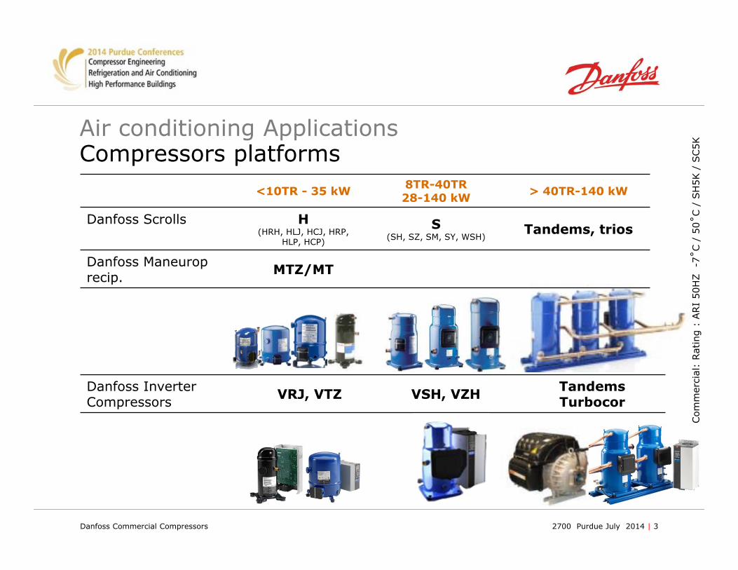
Air conditioning Applications Compressors platforms
<10TR - 35 kW 8TR-40TR28-140 kW > 40TR-140 kW
Danfoss Scrolls H(HRH, HLJ, HCJ, HRP,
HLP, HCP)
S(SH, SZ, SM, SY, WSH)
Tandems, trios
Danfoss Maneuroprecip. MTZ/MT
Com
mer
cial
: Rat
ing
: ARI
50H
Z
-7˚C
/ 5
0˚C /
SH
5K /
SC5K
Danfoss Inverter Compressors VRJ, VTZ VSH, VZH Tandems
Turbocor

Danfoss Commercial Compressors 2700 Purdue July 2014 | 4
Motivation
Get detailed knowledge of the compression process
At design point, and at low and high pressure ratio
Better understand where and when occur the leakages
Analyze the backflow or overshoot phenomena
See the difference between the direct and indirect pockets
Thinly measure the way Intermediate Discharge Valves work
Find some directions for their improvement

Danfoss Commercial Compressors 2700 Purdue July 2014 | 5
Instrumentation of the scroll set
Locations of sensors determined in order to have at least one constantly working in each pocket
Instrumentation phase in the laboratory
A gear is mounted on the upper counterweight
Allows indirect velocity measurement
Gives a reference for the closing/opening of the pockets

Danfoss Commercial Compressors 2700 Purdue July 2014 | 6
ARI point : Evolution of pressures from inlet to discharge

Danfoss Commercial Compressors 2700 Purdue July 2014 | 7
ARI point : PV diagram
Pressures are recombined toestablish the pressure-volume diagram.
It is compared with a theoretical one,based on an assumption of isentropiccompression (in red).
The differences between pockets at theend of the compression appear clearly.
Even at design point, overcompression occurs at discharge.

Danfoss Commercial Compressors 2700 Purdue July 2014 | 8
High Pressure ratio point
Inflexion of the evolution ofpressure at discharge.
Very important backflow fromthe discharge port to the pocket.
Overcompression at the end stillexists.
Very high leakages result in a higherdifference with the isentropic compressionand lower efficiencies.

Danfoss Commercial Compressors 2700 Purdue July 2014 | 9Date | 9
R410A APPLICATION
2025303540455055606570
-30 -25 -20 -15 -10 -5 0 5 10 15 20
Sat Suct Temp °C
Sat D
isch
Tem
p °C
Built in PR
HP (ht)
HP (lt)Over compression
High EER zone
ChillerRoof Top
Simulation & Technology
Light summer conditions for A/C (could be a large % of the yearly running time)

Danfoss Commercial Compressors 2700 Purdue July 2014 | 10
IDV Principle

Danfoss Commercial Compressors 2700 Purdue July 2014 | 11
Compressor with Intermediate Discharge Valves
Location of pressure sensors and of valvesinside the scroll.
One IDV is instrumented to measure its motion.
The valves can be active or blocked.
It is thus possible to compare the way the machine works with or without them, and to quantify the gain in efficiency they bring.
The motion measurement of the IDV helps to understand how the systemcan be improved.

Danfoss Commercial Compressors 2700 Purdue July 2014 | 12
Low pressure ratio point with or without IDV
Evolution of pressure inside the scrolls.with IDV working without IDV
Very effective limitation of overpressure by the valve.Strong gain in efficiencyA certain overpressure is necessary to open the valves.

Danfoss Commercial Compressors 2700 Purdue July 2014 | 13
Pressure-volume diagrams at low pressure ratio Comparison of the PV diagrams
with IDV working without IDV
The IDV allow the machine to run with a good efficiency at points far from the design one.The system could even be improved by reducing mass and stiffness.

Danfoss Commercial Compressors 2700 Purdue July 2014 | 14
ENER Lot 1 ENTR Lot 21 - Overview
2013 2015 2017Adoption Tier 1 Tier 2
ENER LOT1Heating sys
ENTR LOT21A/C sys
2015 2017 2019Adoption Tier 1 Tier 2
Working draft Out (Sep. 013)
Regulation No. 811/2013 Boilers
HP Low T (35C)HP High T (55C)
>86%>115%>100%
>86%>125%>110%
SCOP or SEER per EN14825F(i) = -3% for A/W, B/W & W/W if w/out thermostat
-5% for B/W & W/W due to water pump losses
η% = SCOP / 2.5 – ∑F(i)
η% = SEER / 2.5 – ∑F(i)
A/W Chiller <400kW>400kW
W/W Chiller <400kW>400kW
A/A Chiller
>157% (4.0)>173% (4.4)>196% (5.1)>256% (6.6)>181% (4.6)
>161% (4.1)>185% (4.7)>200% (5.2)>272% (7.0)>189% (4.8)
A/W Chiller up to ≈ 570-600kW cooling capacity (A35/W7), in reversible mode, up to 400kW (-30%) heating capacity (A-10/W35) falls into the requirements of ENER Lot 1 for LOW T HPs
High Temp HP application (A-10/W55) is not achievable with standard A/C compressors (map limitation)
All HPs with reversibility function falls into the requirements of ENTR Lot 21

Danfoss Commercial Compressors 2700 Purdue July 2014 | 15
A/W Reversible ChillerDesign Configuration „GOOD“
Reversible
Ta1C
Tri1C
Tri2C
Ta2C
4.04.1
4.4
4.7
• <400kW IDV technology brings A/W chillers well above Tier 2 levels• The tandem configuration is still weak and requires a more robust system design or different tech (Variable Speed)
• >400kW targets are very high and only Trio 2C w/ IDV gets close to Tier 1• More robust sys design required (EC fans, lower TDE/TDC,…). IDV tech allows for less drastic/expensive sys changes
• SCOP Low Temp targets not a problem. IDV runs at 3-4% points higher than competition and prev. technology
(*) simulation made with 25hp compressors
Standard Danfoss Standard Competition Danfoss IDV
Low Temp. heating mode
125%
Standard Danfoss Standard Competition Danfoss IDV
ENTR Lot 21 ENER Lot 1 – Design Options
A/W Reversible ChillerDesign Configuration „GOOD“:• TDE=3K• TDC=15K• Asymmetric PHX w/ low water side pressure drop• PHX counter-flow in cooling mode• Variable Outlet Water Temp.: 7-11,5 ºC• Full Load cap. derating: -5% (manifolding, suct. acc., 4Way)• Part Load cap. derating: -1,5%• AC condensing fans PWM modulated down to 50% speed• AC-fan power= 9.5% compressor power @ full load
Low Temp. heating mode• TDE=8K @ Tdesign• TDC=5.3K @ Tdesign• Tbiv = Tdesign = 10ºC (no aux back-up)• Defrost derate -5% between 6 and -7ºC• Asymmetric PHX w/ low water side pressure drop• PHX equiflow in heating mode• Variable Outlet Water Temp.: 35-24ºC• Full Load cap. derating: -5% (manif., suct. acc., 4Way)• Part Load cap. derating: -1,5%• AC condensing fans PWM mod. down to 60% speed

Danfoss Commercial Compressors 2700 Purdue July 2014 | 16
Conclusion :
This work brings: Detailed information on the pressure distribution in the scrolls
now available. Measurement of indicated efficiencies. Precious for quantifying leakages and losses. Precise estimation of the gain brought by IDV. Large database available to tune computation models.
The IDV benefit will help to go toward the new EU energy regulation requirement.

Danfoss Commercial Compressors 2700 Purdue July 2014 | 17
THANKS FOR YOUR ATTENTION