Embed Size (px)
Citation preview

35 South Service Road | Plainview, NY 11803-0622 | 88379 | 1-800-843-1553 | caes.com
SCDIPOL Isolated POL (iPOL) Series
DC-DC Converters
DATASHEET REV B: 03/08/21
Features
• Voltage Range - VIN: 26.0VDC to 48.0VDC - VOUT: 0.65VDC to 48.00VDC
• Typical Applications: - For VOUT = 0.65V to 48.0 V
• High Efficiency (>90%) • High Density (up to 162W/in3) • Provide Enable/Disable Control • Zero Voltage Switching / Zero Current Switching (ZVS/ZCS) Quasi-Resonant Converter Topology • Contains Built-in Protection Features
- Input Over/Under-voltage Shutdown - Short Circuit Protection
• Package: Gull Winged Power Package • MIL-PRF-38534 Class L Qualification Pending
Operational Environment
• Temperature Range: -40℃ to +125℃ • Total Dose: 100 krad(Si) • SEL Immune: >80 MeV-cm2/mg
Applications
• Low voltage, high current digital systems • Sensitive low noise high speed ADC and DAC • RF power
Introduction
The CAES iPOLs (isolated Point of Load) Modules excel at speed, density, and efficiency to meet the demands of advanced power applications while providing isolation from input to output. The output voltage of the iPOL tracks its input voltage with a voltage ratio K factor (Vin x K = Vout). These units deliver up to 50A of current with unprecedented efficiency and the smallest footprint in the industry for a radiation hard Point Of Load Converter. Paralleling units delivers even higher power levels. This iPOLs are available in two types of power packages (613xxx and 612xxx) compatible with standard Hi-Rel manual surface mount assembly processes. The fast dynamic response and low noise performance of the these iPOLs eliminate the need for excessive bulk capacitance at the load, substantially increasing system density while improving reliability and decreasing non-recurring cost.

35 South Service Road | Plainview, NY 11803-0622 | 88379 | 1-800-843-1553 | caes.com
SCDIPOL Isolated POL (iPOL) Series
DC-DC Converters
DATASHEET REV B: 03/08/21
Application Examples
Figure 1: Typical Applications;
613xxx Modules Use VC Start-Up Mode; 612xxx Modules use either PC On/Off Mode or Self Start Mode (PC Pin Float, No connect VC Pin)

35 South Service Road | Plainview, NY 11803-0622 | 88379 | 1-800-843-1553 | caes.com
SCDIPOL Isolated POL (iPOL) Series
DC-DC Converters
DATASHEET REV B: 03/08/21
Detailed Block Diagram
Figure 2: Detailed Block Diagram

35 South Service Road | Plainview, NY 11803-0622 | 88379 | 1-800-843-1553 | caes.com
SCDIPOL Isolated POL (iPOL) Series
DC-DC Converters
DATASHEET REV B: 03/08/21
Pinlist Table 1: PIN Numbers and Names for 612XXX iPOLs
Pin No. Signal Pin No. Signal 1 +IN 24 +OUT 2 +IN 23 +OUT 3 -IN 22 +OUT 4 -IN 21 -OUT 5 UV_OUT 20 -OUT 6 OV 19 -OUT 7 CLS 18 +OUT 8 TM 17 +OUT 9 VC 16 +OUT 10 RAL 15 -OUT 11 UV 14 -OUT 12 PC 13 -OUT
Table 2: PIN Numbers and Names for 613XXX iPOLs
Pin No. Signal Pin No. Signal 1 +OUT 40 +OUT 2 -OUTA 39 -OUTB 3 +OUT 38 +OUT 4 -OUTA 37 -OUTB 5 +OUT 36 +OUT 6 -OUTA 35 -OUTB 7 +OUT 34 +OUT 8 -OUTA 33 -OUTB 9 +OUT 32 +OUT 10 -OUTA 32 -OUTB 11 +OUT 30 +OUT 12 -OUTA 29 -OUTB 13 +IN 28 -IN 14 +IN 27 -IN 15 +IN 26 -IN 16 +IN 25 -IN 17 VC 24 UV_OUT 18 RAL 23 OV 19 UV 22 CLS 20 PC 21 TM
Note:
1) The Negative output leads (-OUTA, -OUTB) must be connected TOGETHER on the board as close to the iPOL as possible
35 South Service Road | Plainview, NY 11803-0622 | 88379 | 1-800-843-1553 | caes.com
SCDIPOL Isolated POL (iPOL) Series
DC-DC Converters
DATASHEET REV B: 03/08/21
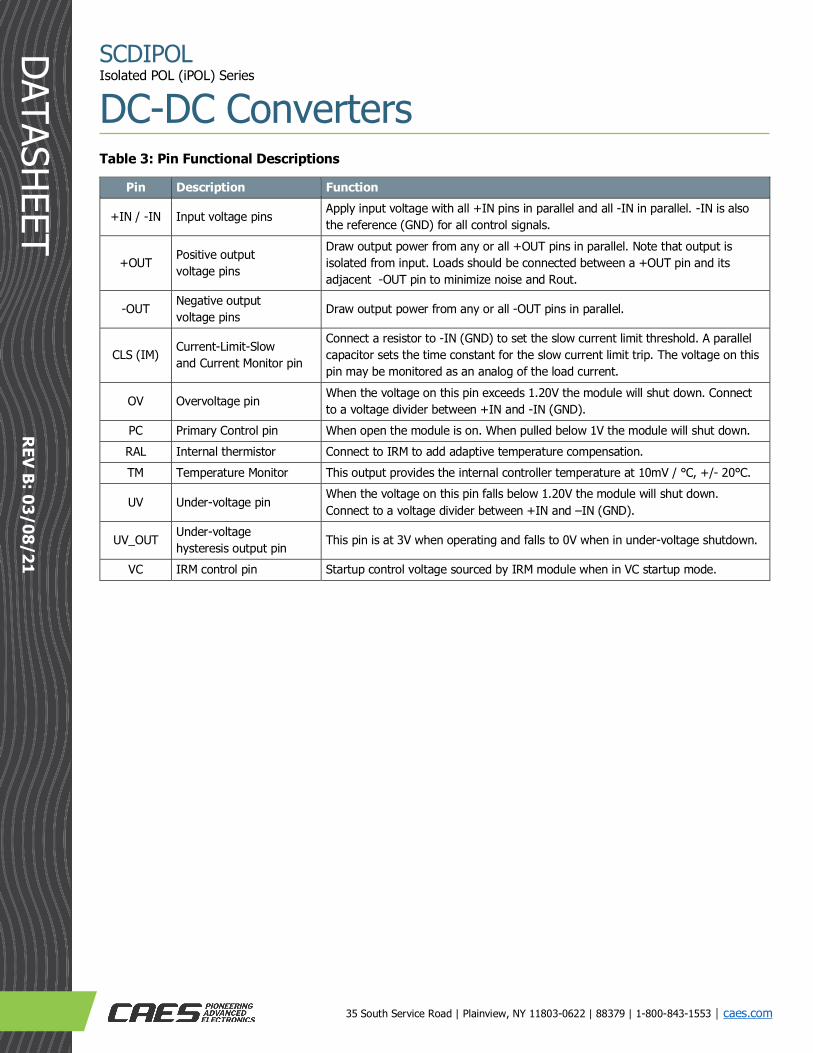
Table 3: Pin Functional Descriptions
Pin Description Function
+IN / -IN Input voltage pins Apply input voltage with all +IN pins in parallel and all -IN in parallel. -IN is also the reference (GND) for all control signals.
+OUT Positive output voltage pins
Draw output power from any or all +OUT pins in parallel. Note that output is isolated from input. Loads should be connected between a +OUT pin and its adjacent -OUT pin to minimize noise and Rout.
-OUT Negative output voltage pins Draw output power from any or all -OUT pins in parallel.
CLS (IM) Current-Limit-Slow and Current Monitor pin
Connect a resistor to -IN (GND) to set the slow current limit threshold. A parallel capacitor sets the time constant for the slow current limit trip. The voltage on this pin may be monitored as an analog of the load current.
OV Overvoltage pin When the voltage on this pin exceeds 1.20V the module will shut down. Connect to a voltage divider between +IN and -IN (GND).
PC Primary Control pin When open the module is on. When pulled below 1V the module will shut down. RAL Internal thermistor Connect to IRM to add adaptive temperature compensation. TM Temperature Monitor This output provides the internal controller temperature at 10mV / ℃, +/- 20℃.
UV Under-voltage pin When the voltage on this pin falls below 1.20V the module will shut down. Connect to a voltage divider between +IN and –IN (GND).
UV_OUT Under-voltage hysteresis output pin This pin is at 3V when operating and falls to 0V when in under-voltage shutdown.
VC IRM control pin Startup control voltage sourced by IRM module when in VC startup mode.

35 South Service Road | Plainview, NY 11803-0622 | 88379 | 1-800-843-1553 | caes.com
SCDIPOL Isolated POL (iPOL) Series
DC-DC Converters
DATASHEET REV B: 03/08/21
Package Pinout Diagram
Figure 3: Package Pinout Diagram for 612xxx iPOLs

35 South Service Road | Plainview, NY 11803-0622 | 88379 | 1-800-843-1553 | caes.com
SCDIPOL Isolated POL (iPOL) Series
DC-DC Converters
DATASHEET REV B: 03/08/21
Figure 4: Package Pinout Diagram 613xxx iPOLs

35 South Service Road | Plainview, NY 11803-0622 | 88379 | 1-800-843-1553 | caes.com
SCDIPOL Isolated POL (iPOL) Series
DC-DC Converters
DATASHEET REV B: 03/08/21
Functional Description Control Functions
There are three ways for an iPOL to be turned on; PC Mode, VC mode and Self Start mode. VC Mode
In VC Mode the iPOL is started by the IRM. This mode is used when the IRM ramps its output slowly from 0V to control inrush currents. The VC pin of the iPOL is connected to the VC pin of the IRM. The IRM provides nominal 8V startup power to the iPOL for 10mS until the iPOL input voltage has risen high enough for the iPOL to generate its own control voltage (approximately 22VIN). The 612xxx iPOLs should not be used in this mode as this mode disables their internal soft start. PC Mode
In PC Mode the iPOL is controlled by its PC pin. The iPOL will start whenever the input voltage is above approximately 22V and the PC pin is open. When the PC pin in pulled to GND (-IN) the module will be off. The VC pin is not used and should be left unconnected. The 613xxx iPOLs should not be used in this mode as they depend on the IRM output rise to for inrush current limiting. Self-Start Mode
In Self-start Mode the iPOL will start whenever the input voltage is above approximately 22V and the PC pin and the VC pin are floating. In this case, the 612xxx iPOLs will soft start up until the output voltage reaches the input voltage times its K factor. At that point, the output will rise as a function of the rise time of the input voltage. The 613xxx iPOLs should not be used in this mode because they depend on the IRM output rise time for soft start. Over-Voltage Detection
The OV pin is used for overvoltage shutdown protection. The pin threshold is 1.20V. An external resistor voltage divider is used to set the input overvoltage level. For example, if a 1.21k ohm resistor is connected from the OV pin to -IN and a 49.9k resistor is connected from +IN to the OV pin, the overvoltage trip point will be 50.7V.
OV Threshold Equation:
�49.9k+1.21k
1.21k �*1.20V=0V threshold
Under-Voltage Detection
The module UV pin is used for under-voltage shutdown protection. The pin threshold is 1.20V. An external resistor voltage divider is used to set the input under-voltage level. For example, if a 1.21k ohm resistor is connected from the UV pin to -IN and a 22.6k resistor is connected from +IN to the UV pin, the under-voltage trip point will be 23.6V.
UV Threshold Equation:
�22.6k+1.21k1.21k
�*1.20V=UV threshold

35 South Service Road | Plainview, NY 11803-0622 | 88379 | 1-800-843-1553 | caes.com
SCDIPOL Isolated POL (iPOL) Series
DC-DC Converters
DATASHEET REV B: 03/08/21
When an under-voltage is detected, the module will shut-down and then restart when the input is back in range. The UV_OUT pin may be used to provide additional hysteresis. When the module is ON, the UV_OUT pin is 3V. When an under-voltage is detected, the UV OUT pin falls to 0V. Hysteresis may be added by connecting a resistor from the UV_OUT pin to the UV pin. A 100k resistor will add about 0.5V hysteresis. Current Limit Slow
The CLS function protects the iPOL from overload currents (prevents thermal overstress of the components within the iPOL). The CLS (IM) pin source current varies in proportion to the output current. Connect a 10Kohm resistor from the CLS (IM) pin to -IN to scale the voltage. The current limit trip point is nominally 1.2V, so the 10k ohms resistor will set the trip point approximately 133% of full output. A capacitor needs to be placed across the resistor to integrate the source current and delay the trip. A capacitor of 0.27μF will give a time constant of 2.7mS resulting in a trip time of 8mS for an overload of 140%. Reduce this resistor to 1Kohms to rely on the internal current limit of the iPOL (and disable the CLS current limit function), which protects the iPOL from short circuit output. Absolute Maximum Ratings (1, 2)
Table 4: Absolute Maximum Ratings
Symbol Parameter MIN MAX Units VIN Positive Supply Voltage -0.3 +55.0 VDC
OV, UV, PC pins Max Voltage on PC, OV and UV Pins -0.3 +4.0 VDC VC Max Voltage on VC Pin -0.3 11 VDC Input to Output Isolation (4) -- 200 VDC
TJ (3) Operating Temperature Range -40 +125 ℃ TSTG Storage Temperature -55 +125 ℃
Notes:
1) Stresses outside the listed absolute maximum ratings may cause permanent damage to the device. This is a stress rating only and functional operation of the device at these or any other conditions beyond limits indicated in the operational sections of this specification are not recommended. Exposure to absolute maximum rating conditions for extended periods may affect device reliability and performance.
2) All voltages referenced to -IN 3) Junction Temperature. Corresponds to a 105C lead temperature at maximum load or no load condition at 115C lead
temperature. 4) All input pins tied together to all output pins tied together

35 South Service Road | Plainview, NY 11803-0622 | 88379 | 1-800-843-1553 | caes.com
SCDIPOL Isolated POL (iPOL) Series
DC-DC Converters
DATASHEET REV B: 03/08/21
Operational Environment (1)
Table 5: Operational Environment
Symbol Parameter Limit Units TID Total Ionizing Dose (2) 100 krad(Si) SEL Single Event Latchup Immunity (3) >80 MeV-cm2/mg
Notes:
1) For devices with procured with a total ionizing dose tolerance guarantee, post-irradiation performance is guaranteed at 25℃ per MIL-STD-883 Method 1019, Condition A up to maximum TID level procured.
2) Per MIL-STD-883, method 1019, condition A (Optional: Per MIL-STD-883, method 1019.9, condition A, with extended room temperature anneal per section 3.11.2)
3) SEL is performed at 125℃ Recommended Operating Conditions (1) Table 6: Recommended Operating Conditions
Symbol Parameter MIN MAX Units TL (2) Case Operating Temperature Range -40 +85 °C VIN Positive Supply Voltage +26 +48 VDC
Notes:
1) All voltages referenced to –IN 2) Lead Temperature of module.

35 South Service Road | Plainview, NY 11803-0622 | 88379 | 1-800-843-1553 | caes.com
SCDIPOL Isolated POL (iPOL) Series
DC-DC Converters
DATASHEET REV B: 03/08/21
Electrical Characteristics (1)
(26V < VIN < 48V, -40℃< TJ <+125℃); Unless otherwise noted. Table 7: DC Electrical Characteristics
Symbol Parameter Conditions MIN TYP MAX Units Input/Output Parameters
VIN Input Supply Voltage 26 - 55 VDC VOVT Over-Voltage Trip Point VIN Rising 1.15 1.23 1.28 VDC
OV Hysteresis 0.030 0.060 0.090 VDC OV Response Time 4.7 µSec
VUVT Under-Voltage Trip Point VIN Falling 1.05 1.195 1.25 VDC UV Hysteresis 0.030 0.060 0.090 VDC
VUV HYST Under-Voltage External Hysteresis Voltage UV Untripped 3.0 3.3 3.6 VDC UV Tripped 0 - 0.2 VDC
PC (2) PC Voltage Enabled (floating PC Pin) - - 4.0 VDC PC threshold 1.0 - 1.2 VDC PC Source Current iPOL Disabled - - 590 µA Enable Response Time - - 440 µSec Output Voltage Rise Time (612xxx Modules Only) 400 - 1000 µSec
VC (2) VC Input Voltage - 10 - VDC VC Pulse width - 10 - mSec VC Load Current - - 200 mA VC to Vout turn-on delay - - 400 µSec
CLS CLS Threshold Voltage 0.89 1.2 1.3 VDC CLS (IM) Source Current Maximum Continuous Load 5 90 125 µA
RAL Thermistor to -IN 25C - 10K ohms TM Temperature Monitor 27C - 2.0 - V Gain - 10 - 10mV / ℃
Notes:
1) All voltages referenced to –IN 2) PC and VC parameters are guaranteed by design and not test.

35 South Service Road | Plainview, NY 11803-0622 | 88379 | 1-800-843-1553 | caes.com
SCDIPOL Isolated POL (iPOL) Series
DC-DC Converters
DATASHEET REV B: 03/08/21
Table 8 Electrical Characteristics Continued; Rout of Each iPOL type in milliohms.
iPOL PN MIN 25℃ Nom MAX MIN 85℃ Nom MAX MIN -40℃ Nom MAX 613140 0.8 1.0 1.2 1.0 1.2 1.4 0.7 0.9 1.2
613132 (2) 1.0 1.3 1.5 1.1.0 1.45 1.65 0.9 1.2 1.4 613124 (2) 1.4 1.6 1.7 1.52 1.79 1.85 1.2 1.5 1.7 612116 5.0 6.4 7.0 6.0 6.4 8.5 5.0 6.0 7.0 612112 6.6 7.7 10.0 6.6 7.4 10.7 6.5 7.0 10.0 612108 14.0 21.0 23.0 16.0 21.0 26.0 14.0 19.0 23.0
612106 (2) 21.0 30.0 32.0 24.0 33.0 36.0 24.0 28.0 33.0 612105 (2) 31.0 37.0 43.0 35.0 44.0 49.0 30.0 35.0 42.5 612104 (1) 37.0 44.0 51.0 44.0 52.0 59.0 33.0 42.0 50.0 612103 (1) 60.0 71.0 98.0 63.0 75.0 94.0 55.0 69 99 612102 (1) 75.0 80.0 85.0 85.0 90.0 95.0 70 75 80 612101 (1) 84.0 96.0 102.0 102.0 108.0 114.0 80 90 96
Notes:
1) Module not yet in production. Parameters are TBR. 2) Contact manufacturer for parameter verification.
Table 9: Electrical Characteristic Continued; Output Characteristics
iPOL K Factor (Vout/Vin)
Max Output Current
Continuous(A) (4)
Max Load Capacitance 48Vin(uF) (2)
Output Ripple Frequency
Minimum MHz (3)
Output Ripple Frequency
Maximum MHz (3)
Max Output Voltage
Ripple mVp^p 613140 1/40 50 5,000 2.51 3.26 340 613132 1/32 50 5,000 2.88 3.52 330
613124 (1) 1/24 37.5 3500 2.88 3.52 220 612116 1/16 16.7 3500 2.88 3.52 250 612112 1/12 12.5 2000 2.40 3.19 250 612108 1/8 8.33 700 2.40 3.19 250 612106 1/6 6.25 400 2.40 3.19 200 612105 1/5 5.2 300 2.40 3.19 260
612104 (1) 1/4 4.17 200 2.40 3.19 220 612103 (1) 1/3 3.125 100 2.40 3.19 480 612102 (1) 1/2 2.1 50 2.40 3.19 175 612101 (1) 1/1 1.04 10 2.40 3.19 250
Notes:
1) Module not yet in production. Parameters are TBR. 2) Values are calculated, not tested. Values indicate ability to start-up module during recommended start-up mode with a CLS
resistance of 10Kohms. 3) Values are calculated for EOL and not tested. 4) Maximum current at which all internal components meet deratings with an 85℃ lead temperature and a 48V input.

35 South Service Road | Plainview, NY 11803-0622 | 88379 | 1-800-843-1553 | caes.com
SCDIPOL Isolated POL (iPOL) Series
DC-DC Converters
DATASHEET REV B: 03/08/21
Table 10 Electrical Characteristic Continued; Maximum no load power dissipation (W) vs. input voltage and temperature (4) and efficiency (2)
iPOL
No Load Vin=26V 25C to 85C
No Load Vin=32V 25C to 85C
No Load Vin=48V 25C to 85C
No Load
Vin=26V-40C
No Load Vin=32V-40C
No Load Vin=48V -40C
No Load Vin=26
V >85C to
125C
No Load Vin=32
V >85C to
125C
No Load Vin=48
V >85C to
125C
Min Efficiency Max Load
Min Efficiency 1/3 Load
613140 3.4 3.7 5.3 4.6 5.0 7.1 4.1 4.4 6.4 88.5% 82.5% 613132 3.3 3.9 5.4 5.5 (3) 6.4 (3) 8.5 (3) 4.1 4.4 6.4 89.4% 84.2%
613124 (1) 3.0 3.3 5.0 4.0 4.5 7.5 3.4 4.0 6.4 89.4% 87.1% 612116 2.0 2.1 2.8 2.5 2.7 4.2 2.4 2.5 3.4 91.5% 87.3% 612112 2.1 2.3 3.4 2.5 (3) 2.8 (3) 4.1 (3) 2.5 2.8 4.1 90.5% 86.6% 612108 2.5 2.5 2.9 3.5 3.5 4.1 3.0 3.0 3.5 91.5% 85.6% 612106 2.1 2.4 3.3 2.5 (3) 2.8 (3) 3.8 (3) TBS TBS TBS 92.5% 90.5% 612105 2.2 2.5 3.5 2.6 (3) 2.9 (3) 4.0 (3) TBS TBS TBS 89.8% 85.0%
612104 (1) 1.4 1.9 2.9 2.9 2.9 3.4 TBS TBS TBS 92.5% 88.5% 612103 (1) 1.5 1.9 2.5 2.9 2.9 3.4 TBS TBS TBS 94.9% 89.2% 612102 (1) 2.5 2.5 2.9 2.9 2.9 3.4 TBS TBS TBS 91.0% 85.6% 612101 (1) 2.4 2.3 3.4 2.9 2.9 3.4 TBS TBS TBS 90.5% 85.0%
Notes:
1) Module not yet in production. Parameters are TBR. 2) Efficiency guaranteed from 25℃ to 85℃ lead temperature. 3) Contact manufacturer for verification of values. 4) Temperatures reflect module lead temperature.

35 South Service Road | Plainview, NY 11803-0622 | 88379 | 1-800-843-1553 | caes.com
SCDIPOL Isolated POL (iPOL) Series
DC-DC Converters
DATASHEET REV B: 03/08/21
Package Drawings
Dimensions in inches.
Tolerances ±.005 inches unless otherwise noted. Figure 5: Package Drawing for 612xxx Modules
Lead Material and Plating
Lead material is Copper, UNS No. C10100 IAW ASTM-B152/B512M. Temper is H02-Half Hard. Plating is Gold Plated, 5-10 micro-inches IAW MIL-DTL-45204, Type I, Grade A, Class 1, over Electrolytic Nickel plated 200-350 micro-inches in accordance with AMS-QQ-P290, Class 1, Grade G. Final finish is Sn60/Pb40.
Table 11: Mechanical Characteristics
SYM Parameter Conditions MIN TYP MAX Unit L Length - - - 1.105 [28.067] in [mm] W Width - - - 1.06 [26.924] in [mm] H Height - - - 0.315 [8.001] in [mm] Wt Weight - - - 16 g
- Soldering tip dwell time per single pin
Tip temperature 600℉ Assembly pre-heated to 125℉ - - 6 Sec
Note: Product is not designed for reflow applications. Manual soldering of leads is required.

35 South Service Road | Plainview, NY 11803-0622 | 88379 | 1-800-843-1553 | caes.com
SCDIPOL Isolated POL (iPOL) Series
DC-DC Converters
DATASHEET REV B: 03/08/21
Conversion
INCH MM 0.001 0.025 0.003 0.076 0.005 0.127 0.010 0.254 0.011 0.279 0.012 0.305 0.013 0.330 0.030 0.762 0.038 0.965 0.050 1.270 0.075 1.905 0.100 2.540 0.270 6.858 0.301 7.645 0.315 8.001 0.816 20.726 0.866 21.996 1.050 26.670 1.100 27.940 1.310 33.274

35 South Service Road | Plainview, NY 11803-0622 | 88379 | 1-800-843-1553 | caes.com
SCDIPOL Isolated POL (iPOL) Series
DC-DC Converters
DATASHEET REV B: 03/08/21
Package Drawings
Dimensions in inches.
Tolerances ±.005 inches unless otherwise noted. Figure 6: Package Drawing for 613xxx Modules
Lead Material and Plating Lead material is Copper, UNS No. C10100 IAW ASTM-B152/B512M. Temper is H02-Half Hard. Plating is Gold Plated, 5-10 micro-inches IAW MIL-DTL-45204, Type I, Grade A, Class 1, over Electrolytic Nickel plated 200-350 micro-inches in accordance with AMS-QQ-P290, Class 1, Grade G. Final finish is Sn60/Pb40. Table 12: Mechanical Characteristics
SYM Parameter Conditions MIN TYP MAX Unit L Length - - - 1.605 [40.767] in [mm] W Width - - - 0.960 [24.384] in [mm] H Height - - - 0.315 [8.001] in [mm] Wt Weight - - - 25 g
-
Soldering tip dwell time per single pin
Tip temperature 600℉ Assembly pre-heated to 125℉
-
-
6
Sec
Note: Product is not designed for reflow applications. Manual soldering of leads is required

35 South Service Road | Plainview, NY 11803-0622 | 88379 | 1-800-843-1553 | caes.com
SCDIPOL Isolated POL (iPOL) Series
DC-DC Converters
DATASHEET REV B: 03/08/21
Conversion INCH MM 0.001 0.025 0.003 0.076 0.005 0.127 0.010 0.254 0.011 0.279 0.012 0.305 0.013 0.330 0.030 0.762 0.038 0.965 0.050 1.270 0.075 1.905 0.100 2.540 0.270 6.858 0.315 8.001 0.716 18.186 0.866 21.996 0.950 24.130 1.050 26.670 1.100 27.940 1.210 30.734 1.310 33.274 1.600 40.640

35 South Service Road | Plainview, NY 11803-0622 | 88379 | 1-800-843-1553 | caes.com
SCDIPOL Isolated POL (iPOL) Series
DC-DC Converters
DATASHEET REV B: 03/08/21
Figure 7
Figure 8

35 South Service Road | Plainview, NY 11803-0622 | 88379 | 1-800-843-1553 | caes.com
SCDIPOL Isolated POL (iPOL) Series
DC-DC Converters
DATASHEET REV B: 03/08/21
Figure 9
Figure 10

35 South Service Road | Plainview, NY 11803-0622 | 88379 | 1-800-843-1553 | caes.com
SCDIPOL Isolated POL (iPOL) Series
DC-DC Converters
DATASHEET REV B: 03/08/21
Figure 11
Figure 12

35 South Service Road | Plainview, NY 11803-0622 | 88379 | 1-800-843-1553 | caes.com
SCDIPOL Isolated POL (iPOL) Series
DC-DC Converters
DATASHEET REV B: 03/08/21
Figure 13
Figure 14

35 South Service Road | Plainview, NY 11803-0622 | 88379 | 1-800-843-1553 | caes.com
SCDIPOL Isolated POL (iPOL) Series
DC-DC Converters
DATASHEET REV B: 03/08/21
Ordering Information Generic Datasheet Part Numbering
Revision History
Date Revision Change Description Initials 03/13/17 A Initial Release CL 03/08/21 B Revised Per ECN 23542

35 South Service Road | Plainview, NY 11803-0622 | 88379 | 1-800-843-1553 | caes.com
SCDIPOL Isolated POL (iPOL) Series
DC-DC Converters
DATASHEET REV B: 03/08/21
Datasheet Definitions
DEFINITION
Advanced Datasheet CAES reserves the right to make changes to any products and services described herein at any time without notice. The product is still in the development stage and the datasheet is subject to change. Specifications can be TBD and the part package and pinout are not final.
Preliminary Datasheet CAES reserves the right to make changes to any products and services described herein at any time without notice. The product is in the characterization stage and prototypes are available.
Datasheet Product is in production and any changes to the product and services described herein will follow a formal customer notification process for form, fit or function changes.
The following United States (U.S.) Department of Commerce statement shall be applicable if these commodities, technology, or software are exported from the U.S.: These commodities, technology, or software were exported from the United States in accordance with the Export Administration Regulations. Diversion contrary to U.S. law is prohibited. Cobham Long Island Inc. d/b/a CAES reserves the right to make changes to any products and services described herein at any time without notice. Consult an authorized sales representative to verify that the information in this data sheet is current before using this product. The company does not assume any responsibility or liability arising out of the application or use of any product or service described herein, except as expressly agreed to in writing; nor does the purchase, lease, or use of a product or service convey a license under any patent rights, copyrights, trademark rights, or any other of the intellectual rights of the company or of third parties.


