Embed Size (px)
Citation preview
IST-101-RSY-024 S1.1
UNCLASSIFIED
UNCLASSIFIED
Demonstrating a Successful Strategy for Network Enabled Capability
Michael Lambert1, Chris Partridge2, Michael Loneragan1, Andrew Mitchell2
1QinetiQ,
Portsdown Technology Park, Southwick Road,
Cosham, Portsmouth,
Hants, PO6 3RU,
United Kingdom
2BORO Solutions Limited
25 Hart Street, Henley on Thames,
Oxfordshire, RG9 2AR,
United Kingdom
ABSTRACT
Responsive, agile, collaborative planning and execution is a key requirement for the development of a
successful Network Enabled Capability (NEC), whether at the national or international level. This paper
makes the case that it is not possible to achieve this agility without solving the semantic interoperability
problem. The semantic issues facing NATO’s Network Enabled Capability (NNEC) are also faced by its
members in their national NECs. There are currently many proposed strategies attempting to address these
issues. Finding the one that will provide the hoped for integration and at the same time only cause minimal
changes to existing infrastructure is a major challenge. In this situation it is vital to be able to demonstrate
the effectiveness of a strategy. This paper presents the findings from a project tasked with both identifying
a strategy and demonstrating its effectiveness - the Joint Tactical Air Defence Integration System (JTADIS)
project. This project was funded by the UK Ministry of Defence (MoD) and undertaken by QinetiQ – the
semantic analysis was undertaken by BORO Solutions.
1.0 INTRODUCTION
Some time ago the UK MoD realised that it had a significant number of Air Defence (AD) Command and
Control (C2) legacy systems that were procured as domain specific and so not capable of being integrated
to deliver the increased agility needed for Joint Force AD. They asked the defence technology company
QinetiQ to formulate an innovative solution and demonstrate it in the Tactical AD-C2 environment using a
representative sample of these existing legacy systems. This was seen as a good test case for the kind of
semantic interoperability needed for Network Enabled Capability (NEC).
This paper describes the implemented QinetiQ PACE-based (Planning And Collaborative Execution)
solution which included an SIE (Semantic Interoperability Engine) from BORO Solutions. It outlines the
physical and semantic architecture that was developed to support this approach – a key feature of PACE and
SIE is a flexibility that allows users to configure data structures as they evolve to meet changing
requirements. It describes how ontology was deployed within that architecture; supporting PACE’s evolving
data structures and providing the SIE with the semantic mappings between the legacy systems.

Demonstrating a Successful Strategy for Network Enabled Capability
S1.1 - 2S1.1 IST-101-RSY-024
UNCLASSIFIED
UNCLASSIFIED
This paper discusses how the problems that JTADIS attempted to solve are a specific example of a more
general situation. As the world security situation changes, coalition forces across NATO will require to
operate with a greater agility. This agility can only be achieved through a tighter integration of processes
and systems, both within nations and across nations. The potential scope is vast; all of the levels of
command, from strategic to operational and tactical are included. It is often at the cusp where tactical
planning runs into execution where this agility is most needed.
2.0 BACKGROUND, MILITARY NEED
According to UK military doctrine, control of the air is fundamental to the success of joint operations and
is normally achieved through a mix of Defensive Counter Air (DCA) and Offensive Counter Air (OCA)
Operations. DCA is primarily executed as Air Defence (AD) operations defined as “all measures designed
to nullify or reduce the effectiveness of hostile air action”1.
The AD commander needs timely access to AD related information across the battle space from AD capable
sensors to be able to employ effectors2 for the protection of friendly and neutral forces. The spectrum of
potential AD threats in deployed operations is increasing as the world security situation changes. It ranges
from conventional high technology air systems such as cruise missiles to improvised weapons employed
asymmetrically. These threats include a number of difficult air targets which present particular detection
and engagement challenges to the AD system. Currently the systems for managing the sensors and effectors
are not particularly dynamic, and improving that dynamism is an obvious way to counter these threats.
In recognition of its importance, substantial resources have been committed to AD C2 capability in recent
years. However, both current and planned systems have, in general, been procured as environment specific
and so have an environment specific architecture (including connectivity, communications systems and
quality of service). This restricts the extent to which dynamic changes to extant plans and current operations
can be implemented. In particular, changes to plans and airspace control procedures that require
coordination between AD assets in the land and either the maritime or air environments are generally
inefficient. The UK MoD perceived a need to remedy this situation and deliver increased flexibility and
dynamism in Joint Force AD in the near term through improved interoperability within current and planned
systems.
3.0 THE DILEMMA
As soon as the need for the agility is accepted and practical solutions are sought, it is not long before the
horns of a dilemma become apparent. The dilemma, in a nutshell, concerns the requirements on dynamic
Collaborative Planning and Execution (CP&E) and an appreciation of the huge investment and momentum
of the existing infrastructure.
Military systems are often created to achieve a particular goal. They grow within a particular culture with
its own terminology and world view. They are designed to support processes and utilise data structures that
support this specialised world view. They are rarely created with interoperability in mind.
CP&E, on the other hand, cannot be effective unless information can not only be shared with sufficient
timeliness, but also that the implications of change, necessary for agility, can be made apparent to all
stakeholders. Sharing this information with the required dynamism cannot be achieved without a solution
to the semantic interoperability problem. If information from a given system is shared in the wider enterprise
without a clear understanding of its semantics then there is always potential for it to be misinterpreted by
1 AAP-6 NATO Glossary of Terms. 2009
2 In the AD context an effector is any system that can be used to ‘effect’ the enemy, an example is a weapon system.

Demonstrating a Successful Strategy for Network Enabled Capability
IST-101-RSY-024 S1.1 - 3S1.1
UNCLASSIFIED
UNCLASSIFIED
other systems with unforeseen results. This is the crux of the dilemma, how to continue to support
specialised planning and operational staff, with their legacy systems that directly support their ways of
working, while at the same time provide infrastructure that allows an enterprise view and all of the benefits
that would bring in terms of collaborative planning, cross-plan consistency checking and change implication
awareness.
Cross-plan consistency checking, determination of the implication of plan change on other plans, decision
support and the visualisation of cross-plan constraints and relationships all require a common information
model capable of representing the totality of the information involved. The JTADIS project recognised this
problem and found a solution that allowed the legacy systems to share information safely with each other,
thus minimising the impact on staff working in specialised areas, while also providing a collaborative
workspace capable of supporting the enterprise view discussed above.
4.0 THE JTADIS PROGRAMME
JTADIS was a £2m research programme that involved other industry partners who provided their own
operational systems to ensure that the final TRL6 system was realistic in terms of the information to be
shared, the type of plan consistency checking and the timeliness required.
TRL 6 is defined as: “Prototype system, which is well beyond that of TRL 5, is tested in a relevant
environment and represents a major step up in a technology’s demonstrated readiness. Examples include
field testing a prototype in a high fidelity laboratory environment or in a simulated operational environment
operating under proposed protocols”3
The in-service NATO Integrated C2 system for Air Operations (ICC) is an integrated C3I environment that
provides information management and decision support to NATO Combined Air Operations Centers
(CAOCs). In JTADIS it was used for airspace management as it is the operational tool used within the UK
Joint Force Air Component Command (JFACC). BAE provided the Ground Based Air Defence Battlefield
Information Systems Application (GBAD BISA). The GBAD BISA is the operational command and control
system for the ground based air defence assets. It runs on the Battlefield Information Infrastructure (BII)
over the BOWMAN communication bearers. Thales provided the MPlanIt Mission Planning System used
operationally to generate low level detailed air mission plans. The JTADIS demonstrator was built on the
Wide Area Distributed Architecture (WADI); a Defence Information Infrastructure (DII) emulator much
used at events such as the Joint Warrior Interoperability Demonstrator (JWID).
It was recognised from the start that the most difficult problem here was semantic interoperability. With the
JTADIS approach, most of the operational systems were not modified and the GBAD BISA had only minor
additions to its interfaces. In spite of this it was shown that the systems could be made to interoperate to
solve realistic problems that could not have been addressed previously. The crucial messages, used in Air
Defence, were the NATO Adapt-P3 Airspace Control Order (ACO) and Air Tasking Order (ATO), imported
from NATO ICC. It was decided early on that a fruitful approach would involve the import of legacy system
information into a common framework where it could be processed in a collaborative planning workspace.
Once the collaborative session is completed the resulting C2 information which had been de-conflicted and
consistency checked could be used to update the legacy systems at the update frequency that they could
handle.
The JTADIS project now had two main problems to solve. First, how to create a common information model
that was expressive enough to handle all of the necessary semantics and extendable enough to model all of
3 See TRL Definitions.pdf in http://www.aof.mod.uk/aofcontent/tactical/techman/content/trl_applying.htm.”

Demonstrating a Successful Strategy for Network Enabled Capability
S1.1 - 4S1.1 IST-101-RSY-024
UNCLASSIFIED
UNCLASSIFIED
the warfare domains required. Second, how to find a technique for importing legacy information from
multiple systems that did not introduce semantic confusion.
The strategy undertaken to progress the first problem area, the creation of a common information model,
involved a semantic analysis of the AD domain resulting in the Joint Tactical Air Defence Ontology
(JTADO). The chosen method was the BORO methodology from BORO Solutions. BORO concentrates on
using existing example data from the domain and constructing a 4 dimensional extensional model of the real
world. This ontology was used to configure the PACE framework. PACE is effectively a publish/subscribe
framework that allows the sharing of a Generic Information Model (GIM) through the propagation of deltas
(changes) to the objects it uses to represent the C2 information. The GIM, as its name implies, is a generic,
user defined object model able to represent C2 information to the level of fidelity required. For example, in
this project it was used to capture the basic patterns of geospatial, tasking, scheduling and resource planning
in the military domain. The configured GIM became an implementation of the JTADO. PACE propagates
these deltas on the change event making C2 updates dynamic whilst minimising the required bandwidth.
The GIM is a layered model in that it supports different courses of action. PACE can therefore be used for
collaborative working across multiple courses of action where different collaborative working groups may
be working in different areas.
The second problem area was addressed with ontological mapping. Here ontologies were created of the
various legacy systems data structures and a mapping defined that allowed a translation to and from the real
world JTADO. These mappings were implemented within a PACE client known as the SIE that dealt with
the semantic translations. Information was thus imported into the PACE GIM safely, with minimum risk of
semantic confusion.
The UK MoD had asked for a demonstration at TRL6 of an innovative way to improve the agility of AD-
C2 legacy systems. JTADIS showed the key interlinked factors in this were the configurable PACE and
SIE application architecture and an innovative ontological analysis that together allowed, semantically
assured, information dissemination.
5.0 ONTOLOGY
Ontology is a relatively new technique in the AD C2 operational environment. For the purposes of semantic
interoperability, the traditional philosophical (metaphysical) notion of ontology is useful4 – where this is
“the set of things whose existence is acknowledged by a particular theory or system of thought.”5 This view
was famously summarized by Quine, who claimed that the question ontology asks can be stated in three
words ‘What is there?’ – and the answer in one ‘everything’. Not only that, but tongue in cheek, he also said
“everyone will accept this answer as true” though he admitted that there was some more work to be done as
“there remains room for disagreement over cases.”6 As these clarifications show, ontology in this sense is
directly concerned with what exists - in what business modellers call the ‘real world’7.
From the perspective of semantic interoperability, each system’s data can be regarded as a ‘theory’ that
acknowledges the existence of a set of objects – its ontology. The task of the ontological analysis process is
then to work out what ‘real world’ objects this data commits to. This is not an easy task as the surface
4 See Kuśnierczyk, W. (2006) for interesting discussion of ontology related terms.
5 E. J. Lowe in the Oxford Companion to Philosophy.
6 In W.V. Quine’s ‘On what there is’ (1948), Review of Metaphysics, Vol. II, No. 5, reprinted in From a logical point of view
(1961).
7 Barry Smith also makes this point, most recently in Smith and Ceusters (2010) – note the criticisms of the ‘The concept
orientation’ in this paper.

Demonstrating a Successful Strategy for Network Enabled Capability
IST-101-RSY-024 S1.1 - 5S1.1
UNCLASSIFIED
UNCLASSIFIED
structure of the data is usually a very poor guide8 (which helps to explain why the data for the same domain
from different systems can have quite startlingly different structures). A key tool in the analysis is a top
ontology to provide a framework with which the analysis is structured.
5.1 The BORO Approach
The BORO Approach was originally developed in the late 80s and early 90s to meet a requirement to re-
engineer legacy systems9. The prime challenge of the re-engineering was to clarify the underlying ontology
of the systems, and the work focused on developing a process for mining ontologies and a top ontology
tailored to form its foundation10. Early feedback on the top ontology established that a key factor was to
make a series of clear ‘metaphysical choices’11 to provide a solid (metaphysical) foundation. A key choice
was for an extensional (and hence, four-dimensional) ontology which provided neat criteria of identity.
Another conscious choice was for a form of ontological realism – which assumes for engineering reasons
that the world which science describes exists and also that the types used in this description also exist12.
Using this top ontology as a basis, a systematic process for re-engineering legacy systems was developed.
From a software engineering perspective, a key feature of this process was the identification of common
general patterns, under which the legacy system was subsumed. It has been substantially developed since
then. Although much of the work (such as this) is in the private domain, elements of it have appeared in the
public domain, including a number of standards. The ISO standard, ISO 15926 – Industrial automation
systems and integration – was heavily influenced by an early version. The IDEAS (International Defence
Enterprise Architecture Specification for exchange) standard is based upon BORO, which in turn was used
to develop DODAF 2.013.
5.2 Aspects of the BORO Approach
Some analysis processes for a common ontology will start with SMEs and a ‘clean sheet of paper’. BORO
works from the premise that experience seems to show that humans (including SMEs) are not particularly
good at specifying the ontology with the degree of accuracy needed for computer systems. That a better
source is working operational systems – these plainly work to a sufficient degree of accuracy for current
operations14. The issue when working with the legacy systems is how to mine the ontology when the surface
structure is often seriously misleading.
One of the approaches BORO uses to investigate the underlying structure is a focus on the legacy data15
(where many other analysis processes focus on the data schema). The issue here is that in most operational
systems users will have had to work around the schema to get the system to perform as required. With the
8 Philosophers make the same point about the true logical form beneath the “surface grammar” of natural language – see Bertrand
Russell’s Theory of Descriptions in (Russell, B. (1905)).
9 Partridge (2005) p. xv-xx has a more detailed history.
10 For a survey of approaches to re-engineering legacy systems see Daga et al. (2005).
11 Partridge (2002c) has some relevant examples. Most introductory textbooks on metaphysics will also provide a number of
examples, though these may not all be of engineering interest.
12 See Smith and Ceusters (2010) for a robust defence of a similar position. See also Smith et al. (2005) for an attack on an
alternative position.
13 The Department Of Defense Architecture Framework (DODAF) official version can be found here: http://cio-
nii.defense.gov/sites/dodaf20/index.html
14 These opposing positions can be seen as rational and empirical. Where the rationalist assumes that he/she can arrive at the
answer by speculation; whereas the empiricist believes that she/he needs to work by observation.
15 See Partridge (2005) Ch. 11, Sect. 4 for more details.

Demonstrating a Successful Strategy for Network Enabled Capability
S1.1 - 6S1.1 IST-101-RSY-024
UNCLASSIFIED
UNCLASSIFIED
result the schema is misleading. Hence the data is a far more trustworthy source for the analysis than the
data schema.
BORO has developed a variety of ways of testing the semantic quality. One task is the devising of a suitable
semantic stress test. In this programme, the collaborative planning and execution environment required data
from a number of legacy systems with quite different data structures which needed to be consolidated,
manipulated and then sent back to the source system. In this situation, feedback on the semantic quality
issues shows up quickly as operational problems. The high quality of the stress test raises confidence in the
semantic quality of the overall system.
6.0 THE SCOPE OF THE JTADIS DEMONSTRATOR
As a first stage in setting the scope, the requirements for a fully fielded capability were drawn up. These
were reviewed by SMEs to establish a scope that would provide a reasonable test for feasibility of the
proposed solution.
The SMEs divided the overall scope into three phases; pre-tactical planning, tactical planning and
engagement. In the pre-tactical planning phase collaboration is primarily involved with shaping the
battlespace; activities such as the positioning of sensors and effectors in response to Intelligence
Surveillance Target Acquisition and Reconnaissance (ISTAR) updates. The tactical planning phase is “last
minute” collaborative planning and execution CP&E; that is, in the final thirty minutes to five minutes of
an engagement. In the engagement phase, that is in the final few minutes, interventions would be more
concerned with such things as target tracking, sensor cueing, engagement veto decisions and the like.
The SMEs determined that a system that could support tactical planning would have the greatest impact on
the final outcome. Hence the J-TADIS programme focused on collaborative planning during ‘last minute’
tactical planning phase and collaborative execution of an engagement.
6.1 Flexibility and Agility
This put a requirement on the J-TADIS capability to support flexibility and agility, and reduce tempo drag
at the tactical level. There are currently limitations in being able to support fast-changing tactical operations
under the UK’s manoeuvrist doctrine. The limiting factors include both technical infrastructure and
procedures. One straight-forward way to achieve flexibility is to maximize the principle enshrined in Joint
Warfare Publication (JWP) 3-63 of de-centralized execution. This demands that control is delegated to the
lowest practicable level commensurate with the requirements implicit in tactical level operations. It was
proposed that J-TADIS should make significantly more de-centralized control practicable through enabling
a collaborative approach to both planning and execution.
6.2 Selecting Representative Legacy Systems
Generally the legacy systems that are used in the AD domain were not designed to share data with other
systems. Furthermore, they usually were not designed to use event driven technologies. This means that
currently the frequency of information transfer is limited to that supported by the legacy system and is often
a manual process. This makes it difficult for such legacy systems to play a role in event driven systems of
systems, such as those designed to support interactive collaborative planning.
The NATO ICC, BAE’s AD C2 GBAD BISA and Thales’ MPlanIt mission planning system were chosen
for the programme as they were good examples of this issue.
For the final TRL6 demonstration a complex and challenging scenario was devised that illustrated how
integrating these operational legacy systems would enable a level of agility that had not previously been
possible.

Demonstrating a Successful Strategy for Network Enabled Capability
IST-101-RSY-024 S1.1 - 7S1.1
UNCLASSIFIED
UNCLASSIFIED
7.0 THE REQUIREMENTS FOR THE JTADIS DEMONSTRATOR
To overcome current limitations of a largely procedural Joint Tactical Air Defence Command and Control
(JTAD C2) infrastructure, J-TADIS sought to expose or externalize (make available) stove piped AD C2
systems making their functionality and information more accessible and dynamic. This would provide a
significantly improved set of services to the wider AD community.
Within this scope, the requirement for J-TADIS crystallized into two main areas. First techniques had to be
developed to enable legacy operational systems to share their information with the wider planning
community within timescales relevant to the tactical planning phase. Secondly, the environment which
would share this information must allow distributed users to collaborate as they manipulated this
information.
Specifically this involved a requirement for two main system functions:
• provision of a common set of information to support identified Joint Force AD activities; and
• access to (existing or new) services that allow users to make effective use of this common
information.
J-TADIS proposed to meet this via two main mechanisms. The first supports the identified joint AD
activities through provision of services that allow wider access to a common set of information, for example
Airspace Control Means (ACMs). The second provides access to existing or new services that allow users
to manipulate and make effective use of this common information, for example, by allowing users access to
collaborative airspace management functionality.
The term ‘collaborative planning’ is widely used but has no clearly agreed upon definition. When the term
is used here it refers to activities supported by systems that enable distributed users to collaborate on the
manipulation of a plan, in such a way that any proposed modifications made by a planner are immediately
available to his colleagues. It will generally be the case that multiple variants of a plan will exist
simultaneously as different groups propose different solutions. These proposals can be thought of as “what
if” scenarios as planners search to determine optimal responses. Military planners are often in competition
for such resources as airspace and assets and regularly have to coordinate activities with other teams, leading
to inter-plan constraints. To successfully manage these types of complex plans at the required tempo,
automated consistency checking is vital to highlight the impact, both within and across plans, of proposed
changes.
It became apparent that an enterprise level framework, capable of managing a wide spectrum of information
types, would be required. Furthermore, this management would have to include elements of collaborative
planning and execution in some sort of structured workspace, i.e. a workspace capable of dynamically
consistency checking operator actions.
7.1 Increased Information Fidelity
The requirement for increased agility implies that more C2 detail should be made available for exploitation.
In airspace control terms, for example, there could be a greater number of smaller High-Density Airspace
Control Zones (HIDACZs) with more and shorter time of validity slots, greater differentiation of targets,
more fidelity in the Rules of Engagement (ROE) and hostile act criteria. This information can be used, for
example, to identify when to relax such things as Weapon Control States (WCS), which is difficult to achieve
with the currently enforced procedural controls. Increasing the information fidelity in this way would impact
the information modelling and the software architectures used to disseminate it, as explained later in the
paper, in the Architecture section.
Demonstrating a Successful Strategy for Network Enabled Capability
S1.1 - 8S1.1 IST-101-RSY-024
UNCLASSIFIED
UNCLASSIFIED
Under normal circumstances, the forces attempting to perform a task at the tactical level know what they
wish to achieve and their immediate concerns. J-TADIS would provide this information in a collaborative
working environment that would enable these forces to utilize a far more bottom-up pro-active request
process. They could, therefore, approach the appropriate superior authority and indicate their level of
knowledge and their ability to execute a task in a particular area, over a certain time frame.
Currently fratricide is prevented by measures designed mainly to separate functions using space and time
factors with large margins designed to reduce potential errors. J-TADIS could improve on this situation as
it has the ability to provide rapid feedback on remote system status, such as WCS. This type of information
can be used to provide additional factors to assist with maximizing airspace usage safely.
7.2 Preserving Individual Communities’ Semantics
Military communities and their systems often emerge with a focus on a particular goal. They develop their
own particular culture with its own terminology and specialized world view. This creates a dilemma in the
Joint Force environment, how to continue to support specialized planning and operational staff, with their
legacy systems that directly support their ways of working, while at the same time provide infrastructure
that allows an enterprise view and all of the benefits that would bring. This is particularly acute in the case
of CP&E, which cannot be effective unless information can not only be shared with sufficient timeliness,
but also that the implications of proposed changes in plans, necessary for agility, can be made apparent to
all stakeholders. Effective CP&E requires, inter alia, cross-plan consistency checking, determination of the
implications of plan change on other plans, decision support and the visualization of cross-plan constraints.
This translates into a requirement to preserve the semantics of the different military communities (and their
systems) in the Joint AD environment while simultaneously providing a single a common semantics for the
totality of the information involved.
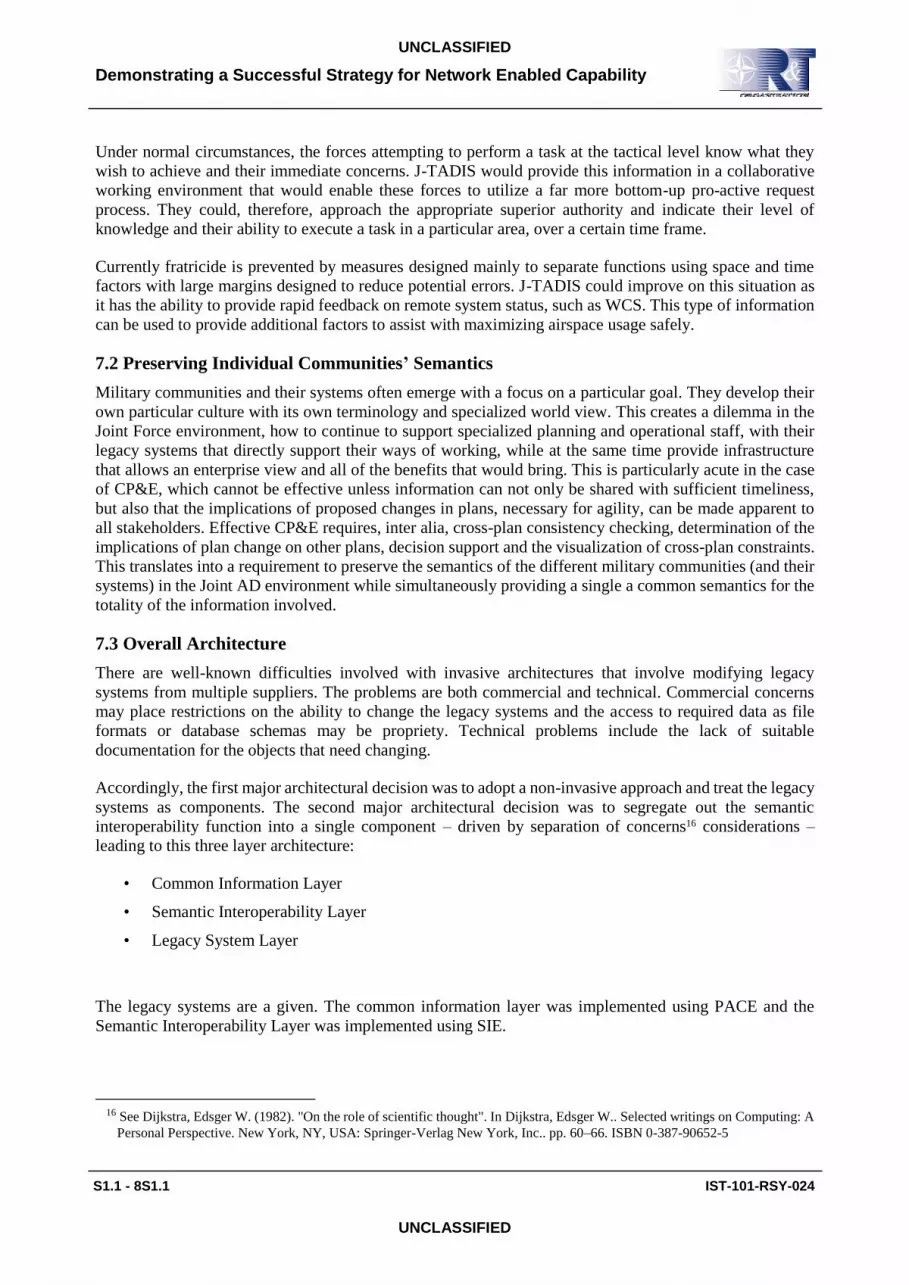
7.3 Overall Architecture
There are well-known difficulties involved with invasive architectures that involve modifying legacy
systems from multiple suppliers. The problems are both commercial and technical. Commercial concerns
may place restrictions on the ability to change the legacy systems and the access to required data as file
formats or database schemas may be propriety. Technical problems include the lack of suitable
documentation for the objects that need changing.
Accordingly, the first major architectural decision was to adopt a non-invasive approach and treat the legacy
systems as components. The second major architectural decision was to segregate out the semantic
interoperability function into a single component – driven by separation of concerns16 considerations –
leading to this three layer architecture:
• Common Information Layer
• Semantic Interoperability Layer
• Legacy System Layer
The legacy systems are a given. The common information layer was implemented using PACE and the
Semantic Interoperability Layer was implemented using SIE.
16 See Dijkstra, Edsger W. (1982). "On the role of scientific thought". In Dijkstra, Edsger W.. Selected writings on Computing: A
Personal Perspective. New York, NY, USA: Springer-Verlag New York, Inc.. pp. 60–66. ISBN 0-387-90652-5

Demonstrating a Successful Strategy for Network Enabled Capability
IST-101-RSY-024 S1.1 - 9S1.1
UNCLASSIFIED
UNCLASSIFIED
7.4 Common Information Layer: Information Modelling and Dissemination Strategies
Within the common information layer, it was necessary to address the current limiting factors in both
information modelling and dissemination.
7.4.1 Key Physical Architecture Requirements
There are three main architectural requirements that impacted the decisions regarding information modelling
and dissemination:
• The trade-offs between fixed models and generic configurable models
• The complexity of managing a variety of plans, each with layers of alternative options, in a dynamic
event driven environment, constrain the architecture in particular ways.
• The performance implications of disseminating generic configurable layered models of this type.
7.4.2 Configurable Generic Models versus Fixed Models
The choice of when to use a generic model over a fixed model is influenced by two main criteria. The first
criterion is the relationship between the scope of the information to be modelled and its potential to be
generalized. If the scope is small then the additional effort required to build a generic system may not be
cost effective. If the scope is large but the information has little potential to be generalized, then the resulting
generic model may not offer much compaction. If, however, both the scope and the potential for
generalization is large then the generic approach will scale better than a fixed model.
The improvement is a function of processing that can be applied at the higher abstract levels of the model
and so does not require re-inventing each time at the detailed level. C2 information concerned with multi-
environment planning and execution has considerable potential to be generalized. The same common
patterns of asset allocation, tasking authority, temporal and geographic space allocation endlessly repeat and
lend themselves to generalization.
The second criterion is the expected stability of the model. If the scope of the information to be modelled is
well understood and is unlikely to be subject to major changes over the lifetime of the system, a fixed model
may be preferable. If, at design time, the final scope is unknown, which is the norm for IT systems, a
configurable generic approach will allow the scope to be increased through changes to the configuration
rather than the software. There are considerable advantages in modelling many warfare environments using
the same generic model. Often planners from different environments, trying to achieve different goals,
compete for assets and geographic space allocation. This has the effect of creating constraints between their
various plans. Modelling those constraints, within a common generic model, allows the impact of proposed
changes to be better understood by the commander resulting in a safer and more efficient operation.
J-TADIS uses information from all three environments air, land and maritime. Its scope encompasses long
term planning through tactical planning to execution. In this context, a fixed information model is likely to
unnecessarily constrain the potential development of the system.
7.4.3 Layered Information
To achieve the required agility, J-TADIS needed to support collaborative working over multiple variants of
plans and courses of action. Consider the case when a number of different alternatives to a plan are to be
maintained. One strategy is to create complete copies of the plan and then modify them. This is inefficient
for storage and for dissemination. If different users are working on different parts of the plan it can become
extremely complex to manage. A better solution is to implement each alternative as a set of changes to the
main plan. For the purposes of this paper we shall refer to this as layered information.

Demonstrating a Successful Strategy for Network Enabled Capability
S1.1 - 10S1.1 IST-101-RSY-024
UNCLASSIFIED
UNCLASSIFIED
Different user groups would need to work on different alternatives. From a technological point of view any
provider of this information would need to know which consumer, required which “slice” through this
layered information. The appropriate information must be constructed for each subscribing user group and
this is not just a filtering problem. This is further complicated when the collaborative planning is considered.
As users manipulate the information, the changes must be distributed to only those subscribers who
subscribe to the alternative being changed.
7.4.4. Efficient Dissemination
CP&E requires the sharing of plans and situation awareness data dynamically as the information changes.
If rapid decision making is the goal, CP&E must occur within, at least, the time limits of a typical human
conversation. The military networks that will host J-TADIS have bandwidth and latency constraints and it
is crucial that information distribution strategies minimize the network footprint. Current military messages
such as the ACO and the ATO are effectively entire plans in themselves. Updates to these plans tend to be
delayed, and then managed in bulk, particularly for detached forces. The information models described
above, however, are implemented as interconnected webs of objects so possibilities exist to disseminate
only the changes (deltas) to individual objects. These deltas can be relatively small. Changing a waypoint
on a route, for example, may take a few tens of bytes.
7.4.5 Review of Potential Architectures
Having defined the key requirements on the architecture, a review was carried out into traditional
architectural frameworks, particularly, real time distributed architectures and message based architectures
such as Enterprise Service Bus (ESB)17.
Real time data distribution architectures can be constructed from technologies such as the Common Object
Request Broker Architecture (CORBA)18 or the more modern Data Distribution Service (DDS)19. Both excel
at the rapid dissemination of messages where the message structures and the type of subscription is well
defined and unlikely to change. They are not so well suited to the type of functionality required for the
common information layer. In fact, for DDS, the only option is to disseminate all layers and force the client
to construct the layer it requires. This is unsatisfactory from both performance and security perspectives.
An ESB requires an Enterprise Message Model (EMM) which is an enterprise wide set of message formats
usually defined according to some meta-model such as the XML20 Schema Definition Language (XSDL).
These EMMs are generally implemented using a fixed set of message formats; see section “Configurable
Generic Models versus Fixed Models” above.
ESBs are usually constructed using frameworks which provide the basic functionality for distribution,
persistence and the addition of services. With these frameworks there is little opportunity for optimizing the
information distribution techniques used, particularly for layered information.
17 For more details on ESB, see David Chappell, "Enterprise Service Bus" (O’Reilly: June 2004, ISBN 0-596-00675-6)
18 The official CORBA standard from the Object Management Group can be found here: http://www.omg.org/spec/CORBA/3.1/
19 The official catalog of the Object Management Group’s DDS specifications can be found here:
http://www.omg.org/technology/documents/dds_spec_catalog.htm
20 The Extensible Markup Language (XML) specification can be found here: http://www.w3.org/TR/REC-xml/

Demonstrating a Successful Strategy for Network Enabled Capability
IST-101-RSY-024 S1.1 - 11S1.1
UNCLASSIFIED
UNCLASSIFIED
7.4.6 PACE/GIM
7.4.6.1 Overview
As the traditional architectures were not suited to the J-TADIS requirements, a new framework was
developed and it became known as PACE.
The PACE framework was designed to support distributed planning teams through interactive group
working sessions. Its Generic Information Model (GIM) can be configured to manage C2 information from
different warfare domains. Its strength lies in its ability to support near real time decision making through
its event driven architecture. The PACE framework employs a service based approach specifically tailored
to provide event driven publish subscription over rapidly changing complex C2 information. It was designed
to manage the further complication of different views of this C2 information representing alternative courses
of action available to the commander.
7.4.6.2 Plugin Architecture
The PACE framework allows a variety of plug-in modules, such as user interfaces, business logic or
interfaces to external systems, to dynamically interact with the GIM. Any proposed changes to the GIM can
be consistency checked, as they happen, so immediate feedback of plan consistency or useful advice is
relayed back to the user.
PACE differs from the traditional ESB in two main ways. It employs a configurable generic approach for
its enterprise data modelling and it uses that genericity to optimize the dissemination, visualization and
processing of that data.
7.4.6.3 Information Handling – The Generic Information Model
The heart of the PACE framework is the GIM. The GIM is a framework that supports ontologies. This
separates technical aspects, such as performance which are built into the framework, from the details of the
content, which are loaded as needed. This is a classical separation of concerns architecture.
The GIM has a top ontology that captures some of the core military planning patterns; including the
relationships between temporal activities, geospatial information, resource allocation, ownership and
control. For a particular application, the GIM is configured with the background ontology for the relevant
domains. This means that PACE-GIM sets no constraints on what C2 domains it can support and to what
level of detail.
When deployed, users and legacy systems can add further information to the GIM through the various PACE
user interfaces. The GIM is then the source for common C2 information for both plan and execution time.
Figure 1 shows a simple example GIM fragment configured as a scheduling and resource plan for aircraft
sorties. The light grey rectangles show classes defined as part of the configuration, the white rectangles
show objects created by the user at plan time. The fragment shows a Tornado GR421 sortie is planned using
the sub-class “GR4 Mission” which requires a resource template modelled as a tree of Resource Slots. At
plan time specific Resources are chosen to fill the Resource Slots tree, comprising in this simple example
as a GR4, a pilot and a weapon. The mission itself is planned to follow a particular route “GR4 Route”.
21 The Tornado GR4 is a variable geometry, two-seat, day or night, all-weather attack aircraft, capable of carrying a wide variety
of weapons.

Demonstrating a Successful Strategy for Network Enabled Capability
S1.1 - 12S1.1 IST-101-RSY-024
UNCLASSIFIED
UNCLASSIFIED
Figure 1 Example GIM structure
7.4.6.4 Information Dissemination – The Generic Approach
The PACE framework is an event-driven publish/subscribe system, its GIM is optimized for object
distribution through a delta mechanism technique which only pushes change. The resulting reduction in
bandwidth footprint is a crucial advantage for many military situations.
The genericity inherent in the GIM is utilized in techniques used by the PACE framework when
disseminating changes. The object distribution modules, which manage the delta mechanism, are
implemented to work with GIM root classes and so can accommodate any configured classes without
software change.
It is possible to finely tune the amount of information disseminated to any particular client and which users
have permission to access or manipulate data using collections of objects called Information Sets (InfoSets),
which are, effectively, the unit of subscription and the unit of permission.
7.4.6.5 Visualization – The Generic Approach
Users can be given a visualization of geospatial and temporal inter-plan relationships in the context of the
whole plan through the use of generic visualization tools that access the plans (from different warfare
domains) kept in the common information layer.
Resource Slot Activity Resource Area Base
GR4 Res Slot
Pilot Res Slot
Weapon Res Slot
GR4 Mission
GR4 Mission
GR4 Res Slot
Pilot Res Slot
Weapon Res Slot
GR4
Resource
Pilot
Resource
Weapon
Resource
Weapon
Resource
Pilot
Resource
GR4 Resource
GR4 Route
GR4 Route

Demonstrating a Successful Strategy for Network Enabled Capability
IST-101-RSY-024 S1.1 - 13S1.1
UNCLASSIFIED
UNCLASSIFIED
8.0 ONTOLOGICAL DEPLOYMENT
The ontological deployment can be divided into two aspects: architectural and content. The architectural
aspect looks at where the ontology is being deployed within the programme. The content looks at what is
being deployed.
8.1 Deployment Architectural Aspects
Architecturally the ontological work is deployed in two main areas: the configuration of the GIM and the
configuration of the SIE.
In the case of the GIM, the ontological model that arises from the analysis is used to build the configuration
of the GIM. In the case of the SIE, the BORO ontological analysis of the legacy systems produces a mapping
from the legacy system data (and so the legacy system API) to the ontology. This can be used to configure
the SIE, which will convert messages from the common PACE format to the legacy system format and back
– as required.
8.2 Deployment Content Aspects
The hardest problem in systems integration is probably semantic interoperability – how one ensures that the
messages between systems work to a common semantics, share sufficiently similar meaning to
interoperate22. Without some way of working with semantics, it is not possible to exchange and use data
such that the meaning of the data sent by one system is sufficiently well understood by the receiving system
that it can process it safely and properly. Currently there are few rigorous methodologies for undertaking
this task.
An alternative and much more rigorous approach is to use ontology to enable the necessary semantic
understanding. This provides a robust solution and is the approach adopted for the J-TADIS programme.
An ontological approach has benefits here as it works directly with the semantics. The BORO approach
selected for this work has the additional advantage that the ontological analysis of the legacy system is
undertaken in a way that provides the mapping between the systems.
8.3 The Ontological Approach to Semantic Integration
The ontological approach assumes that the data structures in the different legacy systems refer to a common
‘real world’ and that the purpose of the ontological analysis is to identify the ‘real world’ objects that are
being referred to. Then the mappings between the legacy systems are intermediated by these ‘real world’
objects. In practice, a mapping between the legacy system data structures and the ontology model is kept
and used as the requirements specification23.
22 See Partridge (2002b, 2002d, 2002g) and Lycett and Partridge (2009).
23 See Partridge (2006) Figure 11.4: Re-engineering our conceptual patterns for picture of this mapping.

Demonstrating a Successful Strategy for Network Enabled Capability
S1.1 - 14S1.1 IST-101-RSY-024
UNCLASSIFIED
UNCLASSIFIED
8.4 Semantic Architecture for AD Legacy Systems Integration
A key semantic architecture decision for AD legacy system integration is whether to be ‘point to point’ or
‘hub and spoke’. In a semantic point to point architecture, semantic mappings are made between the
interfaces of individual systems as required. In a semantic hub and spoke architecture, each application has
a semantic mapping from its interface to the hub semantics – and communications to other systems involve
a mapping from the hub semantics to that system’s interface. In general, a hub and spoke architecture
requires fewer semantic mappings when there are more than three or four interfaces/systems – significantly
less when there are significantly more systems. This suggests that AD systems integration is more suited to
a hub and spoke semantic architecture. Furthermore, the ontological approach suits a hub and spoke
approach.
Note that this is a semantic architecture and places no constraints on the physical network architecture which
could still be point to point – in fact, PACE is implemented as a distributed network of information servers,
there is no single central physical server. In this particular scenario, where the PACE/GIM data structure is
configurable and the home for the collaborative planning data which requires the consolidation of the
information from a range of legacy systems – PACE/GIM is a natural choice for a physical implementation
of the semantic hub. Hence the J-TADIS programme selected a semantic hub and spoke architecture, with
the distributed PACE at its semantic hub.
In a hub and spoke architecture, the responsibility for conforming to the hub semantics can be either placed
upon the spoke interface or integrated outside the spoke system. In the case of legacy systems, where an
interface already exists, there is a good case for managing it outside: this avoids the need to re-open the
development of each of the systems, typically from different suppliers, and enables the integration work to
be consolidated within a single development project, taking advantage of economies of scale. Taking the
ontological approach helps to consolidate these economies of scale. Hence the J-TADIS programme
developed a general SIE framework within which the individual mappings from spoke legacy system to hub
were implemented.
8.5 Semantic Interoperability Layer - SIE
The SIE comprises parsers for the various military messaging (such as the ACO, ATO and Common Route
Definition (CRD)). The parsers use the mappings from the legacy systems to the common AD ontology
produced by the ontological analysis to translate the messages to and from the common format used by
PACE/GIM.
The eventual transformation results in GIM objects where the legacy system information is now in a form
to be processed and visualized with information generated both within PACE and from other legacy systems.
For J-TADIS the SIE was implemented as a web service accessed via a PACE plugin which sent it legacy
system messages for conversion to GIM objects.
The general message translation process is shown in Figure 2 . In the specific configuration used messages
were routed through PACE and so one of the translations was trivial as it was configured with the common
AD ontology. This was used to safely import, for example, ACOs and the ATOs into PACE’s configurable
GIM.

Demonstrating a Successful Strategy for Network Enabled Capability
IST-101-RSY-024 S1.1 - 15S1.1
UNCLASSIFIED
UNCLASSIFIED
Mapping FromSystem A to
Common AD Ontology
Mapping From Common AD Ontology
to System B
Common AD Ontology
ConvertSystem A Message to Common AD Ontology
ConvertCommon AD Ontology to System B Message
System A Message
System B Message
Figure 2 SIE message translation process
The SIE’s configurable structure and production of the configuration from the ontological analysis of the
legacy systems provide a framework for radically simplifying application interface semantic complexity.
The approach also reduces the number of interfaces that would be required if a one to one integration
approach was employed.
8.6 Architecture of the Final System
Figure 3 shows the final J-TADIS architecture – and the legacy system, SIE and PACE layers.
BII
GBAD ICC ASMMPlanit Map Plan TEWA
IFPI SIE BLPI UIPI UIPI IFPI
WADI (DII)
PACE(event driven/client tailored SOA)
Generic Information Model (GIM)
GBAD ACO ACO ATO CRD ACO ATO GIM GIM GIM GIM
Picture
Figure 3 J-TADIS the architecture
The PACE framework runs on the WADI which is used to simulate the DII, the UK’s main military network.
Partners from the defence industry, BAE and Thales, provided their own operational systems to ensure that
the final system was realistic in terms of the information to be shared, the type of plan consistency checking
and the timeliness required. BAE provided their GBAD BISA system. The GBAD BISA is the operational
C2 system for the ground based air defence assets. It runs on the BII over the BOWMAN communication
bearers. Thales provided the MPlanIt Mission Planning System used operationally to generate low level
detailed air mission plans. NATO ICC was used for airspace management as it is the operational tool used
within the Joint Force Air Component Commander (JFACC). Plans initially generated using operational
systems were imported into the PACE framework though the SIE, manipulated during collaborative working
sessions then exported again via the SIE to multiple legacy systems.

Demonstrating a Successful Strategy for Network Enabled Capability
S1.1 - 16S1.1 IST-101-RSY-024
UNCLASSIFIED
UNCLASSIFIED
In further stages plans were modified collaboratively in real time as a Link16 tactical picture feed showed a
change in the tactical situation. These modifications were immediately displayed on the legacy systems in
both the JFACC command centres and land based AD HQs.
9.0 ONTOLOGICALLY DRIVEN IMPROVEMENTS
9.1 Examples of Ontological Improvements
The J-TADIS ontological analysis exhibited the practical qualities of a good information model. A
significant number of underlying general patterns were discovered and this led to a corresponding
simplification and reduction in size of the model. It also led to an increase in unity and explanation as the
integrated structure of real world being represented was made clear. Within the scope of this paper it is not
possible to show the consistent high level of semantic quality that was achieved across the domain24.
The SMEs identified a number of surprising (to them) semantic issues that analysis revealed, which they
felt were important enough to need communicating more widely. We include two examples below –
amended to stay within the constraints imposed by security classifications. These provide a useful
illustration of what the SMEs regarded as significant improvements.
9.2 A General Context
The team found it useful to have a framework to classify the improvements and benefits. For this kind of
work, it is important to provide a practical engineering rather than a theoretical scientific perspective. From
a software systems perspective, the main benefits that an ontological approach aims to provide are25:
• improved inter-operability,
• reducing complexity,
• increasing longevity, and
• technology proofing.
From this ontological modelling perspective, the qualities of a good model (ones that bring practical
benefits) are26:
• relevant precision and sufficient formality,
• sufficient simplicity and relevant generality,
• appropriate unity and explanation,
• relevant fruitfulness, and
• relevant repeatability – re-usability.
24 In addition, the contents of the ontology are classified and so cannot be made publicly available.
25 For more details see Partridge (2002g) p. 4-5.
26 For more details see Partridge (2002g) p. 22-26.

Demonstrating a Successful Strategy for Network Enabled Capability
IST-101-RSY-024 S1.1 - 17S1.1
UNCLASSIFIED
UNCLASSIFIED
Interestingly, these are generally recognized as the qualities that characterize good scientific theories.27 28
9.3 Real World Semantics Driving Relevant Precision
Within the programme, there were a number of cases where insisting on a clear real world semantics under
a well-defined top ontology led to a clear relevant increase in accuracy. One telling example was the analysis
of exactly what the ACMs’ data in ACOs referred to. This is particularly pertinent to NATO as it manages
the Adapt-P3 standard of which the ACO is part.
Essentially an ACM is a portion of airspace – one that is used for some purpose. Prior to the introduction of
computers, these were described using simple geometric figures drawn on maps with standard ruler,
compass and protractor and then associated with a minimum and maximum height – as shown in Figure 4.
Map
Radius
Vertical Projections
Altitude Band
Altitude 1
Altitude 2
1.1 Mark Centre on Map1.2 Draw Circle on Map1.3 Mark Altitude 1 and 2 on Map
Centre
Figure 4 Representing an ACM on a map
For example, a Restricted Operating Zone (ROZ) around an artillery battery would be drawn as a circle on
the map, with the battery as its centre and the radius based upon the battery´s range. The minimum height
would be ground level and the maximum height determined by the battery’s range.
A standard set of figures was codified and these evolved into the data structures in the current messages –
which provide the inputs29 to an algorithm to calculate the extent of the airspace. Interestingly, the
ontological analysis of these data structures, their associated documentation and existing working practices
clearly showed their map-based roots. More importantly the analysis also revealed a number of possible
different algorithms and so interpretations of the airspace boundaries30.
The map as a representation can be regarded as a Euclidean plane in which the constructed geometric figures
are regular. However, when interpreting these figures in terms of the Earth´s surface (or some idealization
27 See the similar list in the penultimate chapter of Kuhn (1962) and Kuhn (1977) – where, interestingly, he says “I am suggesting,
of course, that the criteria of choice with which I began function not as rules, which determine choice, but as values, which
influence.”
28 The BORO ontological analysis was designed as a systematic process that provides a level of assurance that these semantic
qualities have been scrutinized – providing a form of semantic quality assurance.
29 Interestingly, these seem to be a good example of Fregean senses (see Frege (1892)) – a way to identify the object.
30 As the algorithm is not made explicit anywhere in the documentation – or known to the SMEs – there is no real basis to
determine which was originally intended. A reasonable conclusion would be that this was left vague.

Demonstrating a Successful Strategy for Network Enabled Capability
S1.1 - 18S1.1 IST-101-RSY-024
UNCLASSIFIED
UNCLASSIFIED
of it – for example, WGS (World Geometric System) 84), one needs to invert the original projection (which
could be of a variety of types) and this distorts the neat geometric figures drawn on the map. The current
data structures have resolved this map projection issue by stipulating idealized reference ellipsoids (such as
WGS 84) as their starting point.
However, we found that there are additional sources of semantic indeterminacy that have not been resolved.
We concentrate upon one of these here – the algorithms for estimating the exact extent of the airspace when
projecting the surface figures (of whatever shape) onto the minimum and maximum heights given. The
analysis unearthed several possibilities, each of increasing accuracy. We developed an example using this
ACM data:
Shape: Circle – centre 24° 01' 15''N, 055° 53' 42''E, radius 15 km.
Height: Minimum 15,000 ft, Maximum 35,000 ft.
This data is shown graphically in Figure 5 (making some simplifying assumptions). This shows clearly that
the data does not directly represent the ACM airspace, rather it is the input to an algorithm that calculates
where the ACM airspace is.
99,900 ft
35,000 ft
15,000 ft
24°01'15''N, 055°53'42''E
15.0 km
0 ft
Figure 5 Graphical view of the ACM data
9.4 Lack of Supporting Documentation
The ontological analysis process requires the identification of the airspace being represented. One of the
issues we faced was that there was nothing in the data structure or associated documentation that gave any
hint of what algorithm we should use. Furthermore, the SMEs had not considered the issue and had no
intuition of which was intended. However, when we proposed particular interpretations and found practical
issues, the SMEs offered useful guidance. Lack of documentation is a very common issue when dealing
with legacy systems, and an ontological approach, such as BORO, is an excellent way of compensating for
this31.
31 For more, see Daga et al. (1995).

Demonstrating a Successful Strategy for Network Enabled Capability
IST-101-RSY-024 S1.1 - 19S1.1
UNCLASSIFIED
UNCLASSIFIED
9.5 Cylindrical Projection Interpretation
When starting the analysis, we first assumed that the airspace is an extrusion of the surface circle, in other
words, a cylinder. And that the minimum and maximum heights are cross sections at right angles to the
height axis. (To simplify the explanation, this description assumes the height axis is a normal to the idealized
surface and not, for example, through a notional centre. It also assumes that the circle is drawn on a plane
at a tangent to the idealized surface.) The resultant extruded cylinder and its airspace segment is shown in
Figure 6.
0 ft
15.0 km
99,900 ft
24°01'15''N, 055°53'42''E
35,000 ft
15,000 ft
ACM
Extruded
Surface
Figure 6 Cylindrical extrusions
However, we soon realized that practical considerations suggested that this was not an ideal interpretation.
If two surface circles whose edges touch are drawn on the surface, then there will be a gap between their
extruded airspace segments, as their normal height axes (and so cylinders) will not be parallel (this applies
to any contiguous figures) – see Figure 7. In practice, one needs airspaces that are contiguous to enable air
traffic to pass from one airspace into another.
0 ft

Demonstrating a Successful Strategy for Network Enabled Capability
S1.1 - 20S1.1 IST-101-RSY-024
UNCLASSIFIED
UNCLASSIFIED
Figure 7 Incompletely contiguous cylindrical extrusions
9.6 Conical Projection
To resolve this, we considered an interpretation that extrudes the edges of the circles along normals at that
point on the surface. As before, the minimum and maximum heights are cross sections at right angles to the
central height axis. This results in a conical shape shown in Figure 8. Under this interpretation, if two figures
are contiguous at the surface, they are contiguous at all heights.
0 ft
15.0 km
99,900 ft
24°01'15''N, 055°53'42''E
35,000 ft
15,000 ft
ACM
Extruded
Surface
Figure 8 Conical extrusion
However, after further consideration, we realized that this interpretation also has practical issues. The height
of the airspace varies as the height cross-section is not parallel to the (idealized) surface of the earth – as
shown in Figure 9. If an aircraft were to fly along the lowest level of the airspace from the centre of one of
two touching circles to the other centre, then it would have to gain height as it flew towards the edge of one
circle and then lose height as it flew to the centre of the other – a less simple manoeuvre than just maintaining
height. One would expect that it should be able to just maintain its height.

Demonstrating a Successful Strategy for Network Enabled Capability
IST-101-RSY-024 S1.1 - 21S1.1
UNCLASSIFIED
UNCLASSIFIED
Figure 9 Abutting conical extrusions
9.7 Elliptical Segment
We resolved this by shifting our interpretation of the maximum and minimum heights. We considered a
height to be an extruded surface, where at each point, the distance between the surface and the extruded
surface was the same. Then the top (or bottom) of the airspace was the intersection of the cone (considered
above) and the relevant extruded height – illustrated in Figure 10. This ensured that the height at the top and
bottom of the airspace remained consistent throughout the airspace.
0 ft
15.0 km
99,900 ft
24°01'15''N, 055°53'42''E
35,000 ft
15,000 ft
ACM
Extruded
Surface
Figure 10 Extruded ellipsoidal altitudes

Demonstrating a Successful Strategy for Network Enabled Capability
S1.1 - 22S1.1 IST-101-RSY-024
UNCLASSIFIED
UNCLASSIFIED
The issue is perhaps clearer if one considers an airspace that is sufficiently big such that the curvature of the
idealized Earth has a significant effect.
9.8 Increases in Accuracy
In most cases the increases in accuracy here are relatively small, measured in tens of meters – as shown by
calculations in Figure 11. One could argue the accuracy was (and, to some extent, still is) sufficient, but it
is becoming more of an issue now and will increasingly become one in the future. As the management of
airspace becomes more automated, there is a corresponding need for this management to be more reliable.
Where there are a range of possible interpretations, it is likely that different equipment will use different
interpretations. In this case, they are likely to show different results. For example, one threat assessment
system will show an incursion into an airspace and the other will not – and there is no way of determining
which is right. Where, as here, these differences are endemic then the trustworthiness of the system is
undermined. Furthermore, with the introduction of new types of air vehicles, such as UAVs, it is likely that
the required degree of accuracy will increase to avoid air collisions. This is not feasible without stipulating
an interpretation.
q
q
Shape half-width W Error
Height
6371 km (m
ean ra
dius o
f Ear
th R E)
Cylinder Wall Normal
W/RE = tanq = q for small angles(shape small compared to size of Earth)Error/Height = tanq = q for small anglesSo Error = Height × W/RE
If the shape is an air corridor of half-width 1 km then the error would be height in km divided by 6371. At 10 km height, this would be 1.6 m. For an air corridor 10 km wide, the error would be 16 m.
Figure 11 Error between Cone and Cylinder Projection
9.9 Ontologically Vague Intentional Objects
These airspaces are intentionally constructed, and so the correct interpretation is determined by the intention
of the relevant authority. We spent some time investigating what the intention was. As far as we could
determine, there was no consideration of the issues raised here. As often happens, the data structures evolved
without any detailed consideration of their accurate interpretation. So, as we understand it, there is currently
no intentional support from the relevant authority for any of the interpretations. Hence, from a (theoretical)

Demonstrating a Successful Strategy for Network Enabled Capability
IST-101-RSY-024 S1.1 - 23S1.1
UNCLASSIFIED
UNCLASSIFIED
ontological perspective, it would seem that the airspaces are vague or indeterminate objects (under whatever
account of vagueness or indeterminacy one holds32). However, we had a more practical perspective. The
ontological analysis has identified this vagueness and there is now a need for the relevant authority to decide
upon which interpretation they intend (or would have intended) that will provide a suitably accurate
foundation for agile air systems.
One of the reasons this issue may not have been spotted earlier is that unless one takes an ontological stance,
one can proceed without trying to directly identify the airspace. For example, when making a threat
assessment, one only needs an algorithm that determines whether given the ACM input data and the threat
position, whether the threat is inside the ACM airspace. The airspace does not need to be directly calculated.
Quality assurance may then check that this algorithm is working properly. As only one algorithm with its
implicit assumptions about the interpretation is being used, the vagueness will not be discovered. It is only
when multiple systems, using different algorithms, are tested that an issue is likely to be found.
9.10 Example of Fruitfulness
The use of a four-dimensional ontology threw up some interesting examples of fruitfulness. We developed
an example that relates to the efficient use of airspace, which is described below.
In the ontology model, the shape of the airspace was separated from the other mechanisms of air control
measure. This modularization (separation of concerns) meant that the introduction of new airspace shapes,
which happens from time to time, could be easily accommodated without changes elsewhere. Furthermore,
the use of a four dimensional ontology mean that all the current shapes were captured from a four
dimensional perspective – and so facilitate the introduction of new four-dimensional shapes.
What is not immediately obvious to many users of the ACMs is the constraints that the current allowable
airspace shapes have. Our analysis showed quite clearly their map/ruler/protractor origins – each shape is
easily drawn using those instruments (even though they have not been used to draw the shapes for decades)
and the current data structures reflect these origins. These shapes are two dimensional in origin and extruded
(as the discussion of interpretations above shows) to a third dimension.
This is reflected in the data structures, where the surface 2D shape data is stored separately from their 1D
height data. This segregation places constraints on the possible shapes. In the case of the battery ROZ, a
spheroid shape that more accurately captured the range limits of the artillery would be better than a cylinder
or cone – the two shapes are shown in outline in Figure 12 – where the savings in airspace are also clear.
However, the 3D spheroid shape cannot be described within the 2D + 1D constraints of the current data
structure.
32 See Williamson, Timothy (1994) Vagueness for one recent account of vagueness.

Demonstrating a Successful Strategy for Network Enabled Capability
S1.1 - 24S1.1 IST-101-RSY-024
UNCLASSIFIED
UNCLASSIFIED
3D Shape in 2D Extrusion
Figure 12 3D shape in 2D extrusion
However, there is a further historical constraint that this 2D + 1D brings (and that a 3D approach does not
solve), that is not so immediately obvious. The use of a 4D top ontology in the analysis encourages a 4D
perspective, and from this perspective the constraint can be clearly seen. From this perspective, each of these
2D+1D / 3D shapes can be seen as persisting unchanging though time. This happens because the space shape
is described separately from its 1D time element – in data terms, it is described using a start and end time.
In other words, the data structure has a 2D+1D+1D structure. This example shows a constraint upon the use
of airspace that this 2D+1D+1D structure brings with it.
When reviewing the data sample, we came across entries in the text section of the message that described
how airspaces were to be used (divided between) a number of airspace users. From an analysis perspective,
the use of text fields often signifies a situation where the information cannot be fitted into the structured
data. This turned out to be the case here. The typical situation was an airspace corridor where traffic was in
one direction. Normally aircraft would book a time slot in the airspace and each aircraft use its timeslot – as
shown in the first space-time map in Figure 13. However, in this situation, it is safe and a more efficient use
of airspace for aircraft to enter one end of the airspace before the previous aircraft had left the other end.
The text advises the ad hoc rules for managing this. Clearly this is a workaround made necessary by the
constraints inherent in the data structure.

Demonstrating a Successful Strategy for Network Enabled Capability
IST-101-RSY-024 S1.1 - 25S1.1
UNCLASSIFIED
UNCLASSIFIED
LOW
EST
SPEE
D
IDEA
L SP
EED
HIG
HES
T SP
EED
LOW
EST
SPEE
D
IDEA
L SP
EED
HIG
HES
T SP
EED
spac
e
time
LOW
EST
SPEE
D
IDEA
L SP
EED
HIG
HES
T SP
EED
LOW
EST
SPEE
D
IDEA
L SP
EED
HIG
HES
T SP
EED
spac
e
time
Mission 2Mission 1
Mission 1 Mission 2
Unavailable Available BookedFlight Path
Figure 13 More economic use of airspace
The constraint that is being worked around here is the separation of space and time – and only allowing
booking in time slots. From a four dimensional perspective, if one is booking airspace for an aircraft, it
would make sense to book a shape that reflected the aircraft’s flight path with a tolerance for any deviations
– to consider its path in four dimensions. The resulting airspace is shown in the second space-time map in
Figure 13– the increase in airspace utilization is clearly visible. Note also that the shape from a 3D
perspective (the ‘space’ axis in the diagram) changes over time – increasing in size to reflect the tolerance
needed to handle the potential variations in speed. As there is no persisting 3D shape – one needs to describe
the shape in four dimensions.
When the SMEs had time to reflect upon this, they found a number of situations where this kind of more
efficient use of airspace would be useful. One example they provided was long flights – such as from Diego
Garcia to Europe. These could not be planned using a single corridor, as then the whole airspace would need
to be commandeered for the time of the whole flight. This is not practical when airspace is busy – as it is in
Europe. Instead a large number of smaller spatially and temporally aligned corridors had to be booked. This

Demonstrating a Successful Strategy for Network Enabled Capability
S1.1 - 26S1.1 IST-101-RSY-024
UNCLASSIFIED
UNCLASSIFIED
turned out to be time consuming, especially during the planning phase where a change to one corridor had
to be rolled out across the rest of the chain to keep them aligned.
9.11 The Nature of Subject Matter Expert Expertise
The SMEs played a vital role in the ontological analysis. However, this turned out to be different in some
key respects from the role they are traditionally expected to play; where they are expected to technically
verify the final deliverable is appropriate for their domain. Implicit in this practice is the assumption that
they have the expertise to make this validation. We found that the SMEs had great difficulty in making any
kind of independent technical assessment of the ontology – this could only be carried out by a team including
both SMEs and ontologists. Furthermore, the SMEs had great difficulty in articulating their knowledge in a
form that could be directly represented and comprehending the representations when these were produced.
It appeared that their expertise was not easily translated to or from the ontological representations – and that
this was not due to the nature of the representations.
Our experience on this programme reinforced experiences on previous ontological analysis projects and
enabled us to articulate the underlying issue. We have come to the view that the traditional approach is
seriously flawed. Indeed, we think most experienced practitioners realize this and most successful projects
only pay lip service to the practice. We have done some initial research to characterize the problem and
document it here. This should help to make the case for more analysis.
Typically, an SME is an individual who exhibits the highest level of expertise in performing a specialized
job, task, or skill within an organization. However, expertise in performing a task is not the same as expertise
in understanding and articulating that task – this is captured in the distinction between know-how33 and
know-that (or know-what)34. Indeed, becoming an expert may involve letting go the conscious understanding
of what one is doing. John Searle (1983, 1995) describes how becoming expert in a task one moves from
conscious control to unconscious action, where one has no access to a picture in one’s mind of what one is
doing. Searle calls this the ‘background’. One key aspect of Searle’s analysis is that the more expertise one
has, the less one has an internal representation of that expertise (or conscious access to that representation).
This accorded well with our experience on the programme.
Further evidence for this analysis comes from situations where experts need to provide an explanation of
their expertise. In some case, they, post hoc, rationalize one. As the expert has no access to his/her tacit
knowledge, there is no guarantee that this rationalization will be correct. Shaffer and McBeath (2005)
provide a good example: where expert baseball players provide a completely false rationalization of how
they catch a fly ball.
This characterization of expert knowledge has implications for the use of SMEs during analysis. It implies
that they are not a good source for determining what exists in the domain when aiming for a fine grained
ontological model and that they are not best equipped to independently technically verify the final
deliverable as a good picture of the domain. The methodology needs to harness their expertise in more
appropriate ways.
This also has implications for the nature of the analysis. When the SME is regarded as having a picture
(representation) of the domain in his/her head, the analysis consists in extracting the details of the picture.
However, if no such picture exists (or it is not accessible), then a different approach is required35. The
33 See Polanyi (1966) for a description of know-how as tacit knowledge.
34 See Ryle (1949), Chapter 2 - Knowing how and knowing that.
35 For other examples of this approach see Partridge (2001, 2002a, 2002d, 2002f, 2002g)

Demonstrating a Successful Strategy for Network Enabled Capability
IST-101-RSY-024 S1.1 - 27S1.1
UNCLASSIFIED
UNCLASSIFIED
analysis then becomes a kind of 'rational reconstruction'36 of the model that would have been constructed if
such explicit knowledge was available from the evidence provided by the SME and other sources. A key
element in the analysis is ‘inference to the best explanation’37 or perhaps more accurately ‘inference to the
best interpretation’.
10.0 FURTHER WORK
As often happens with innovative work, the implementation of the solution suggested a number of further
areas of work.
10.1 PACE and SIE Frameworks
For non-generic and non-configurable systems the cost of creating distribution and persistence infrastructure
is a function of the number of message types to be distributed. For generic configurable systems, the work
is primarily concerned with the configuration process. This had a large manual element in the PACE/SIE
implementation. In future research, it will be worth looking at how this could be automated.
10.2 The Generality of the Solution
As far we could tell there is nothing in the nature of the solution that is specific to AD. It should be possible
to apply the approach to any domain where there are a significant number of legacy systems that need to be
integrated. The team have been involved in using elements of the solution in a variety of projects, so have
confidence in it working elsewhere, it would be interesting to see how generally the specific PACE and SIE
solutions developed here could be applied.
10.3 Coding Reduction Impact of the General Patterns in the Ontology
One of the software engineering benefits of the BORO ontological analysis is the identification of general
patterns. Several members of the development team noted that this led to a significant reduction in code38.
Further work could be done to confirm that this happens and investigate how this works, the factors that
affect it and the potential scale of reduction.
11.0 CONCLUSIONS - WHAT DID THE RESEARCH SHOW
The UK MoD asked for a demonstration, at TRL6, of an innovative cost-effective way to improve the agility
of AD-C2 legacy systems. One of the key systems used in the UK JFACC, and a primary data source for
the JTADIS demonstrator, was the NATO Air Operations system ICC. It is likely therefore that any
conclusions reached in this research will be of interest to NATO analysts.
The required improvement in agility was demonstrated using ‘last minute’ CP&E as the test case. The two
interlinked key factors in this were the configurable PACE and SIE application architecture and an
36 For more details of rational construction see, for example, Carnap (1928) and Habermas, J. (1998) who says that "we can
distinguish between know-how, the ability of a competent subject who understands how to produce or accomplish something,
and know-that, the explicit knowledge of how it is that he is able to do so" and
“…[In rational reconstruction] the distinction between drawing on a-priori knowledge and drawing on a-posteriori knowledge
becomes blurred. On the one hand, the rule consciousness [i.e. intuitive know-how] of competent subjects is for them an a-priori
knowledge; on the other hand, the reconstruction of this calls for inquiries undertaken with empirical [methods]”.
37 See, for example, Lipton (1991) for more details. See also McCarthy’s (1980) discussion of circumscription. Earlier Peirce
(1906) called this abduction –saying that “Long before I first classed abduction as an inference it was recognized by logicians
that the operation of adopting an explanatory hypothesis -- which is just what abduction is -- was subject to certain conditions.
Namely, the hypothesis cannot be admitted, even as a hypothesis, unless it be supposed that it would account for the facts or
some of them.” He also more light-heartedly said “Abduction is no more nor less than guessing”.
38 See Partridge (2005) Ch.6, Sect. 3 - An environment that encourages compacting for more background details.

Demonstrating a Successful Strategy for Network Enabled Capability
S1.1 - 28S1.1 IST-101-RSY-024
UNCLASSIFIED
UNCLASSIFIED
innovative ontological analysis that together allowed rapid, semantically assured, information
dissemination.
From a systems development perspective, the research demonstrated the symbiosis of the ontological
approach and system configurability in a situation where data structures can evolve. The ontological analysis
provided the configuration; the systems provided the capability to consume it. It also demonstrated the
benefits of a configurable application in an environment where the data structures are evolving.
From an interoperability perspective, the research demonstrated the feasibility of building a system of legacy
AD-C2 systems with a level of semantic quality sufficient to support challenging applications such as ‘last
minute’ CP&E.
From an ontological perspective, the research demonstrated the benefits of an ontological approach that
could mine a collection of legacy systems for a common AD ontology and produce mappings from the
legacy system data structures to this ontology with a consistently high level of semantic quality assurance.
It also highlighted the usefulness of an ontological realism as a strong basis for producing an integrated
picture across the range of legacy systems.
12.0 ACKNOWLEDGEMENTS
We are grateful to Cdr Jerry Woods RN, the MoD sponsor for this programme, for his substantial help and
support. We are grateful to Bob Curtis (QinetiQ), our prime SME, for the invaluable help he gave us. We
are grateful for the support of our collaborators, BAE Systems and Thales. We are grateful to QinetiQ and
BORO Solutions for allowing us to use material from their reports.
13.0 REFERENCES
[1] Carnap, R. (1928): Der logische Aufbau der Welt, Berlin-Schlachtensee
[2] Daga et al (2005). Daga, A., de Cesare, S., Lycett, M. and Partridge, C., An Ontological Approach for
Recovering Legacy Business Content, HICSS'05 BURA
[3] Frege, G. (1892). ‘Über Sinn und Bedeutung’, in Zeitschrift für Philosophie und philosophische Kritik,
100: 25-50. Translated as ‘On Sense and Reference’ by M. Black in Translations from the
Philosophical Writings of Gottlob Frege, P. Geach and M. Black (eds. and trans.), Oxford: Blackwell,
third edition, 1980.
[4] Habermas, J. (1998) On the Pragmatics of Communication. The MIT Press.
[5] Kuhn, T. (1962). The Structure of Scientific Revolutions. Chicago: University of Chicago Press, 1962.
ISBN 0-226-45808-3
[6] Kuhn, T. (1977). Objectivity, Value Judgment, and Theory Choice in The Essential Tension: Selected
Studies in Scientific Tradition and Change. University of Chicago Press. pp. 320–39.
[7] Kuśnierczyk, W. (2006) Nontological Engineering, Proceeding of the 2006 conference on Formal
Ontology in Information Systems: Proceedings of the Fourth International Conference (FOIS 2006)
ISBN:1-58603-685-8
[8] Lipton, P. (1991): Inference to the Best Explanation (London: Routledge)
[9] Lycett, M. and Partridge, C. (2009). The challenge of epistemic divergence in IS development.
Communications of the ACM. Volume 52 Issue 6, June 2009.

Demonstrating a Successful Strategy for Network Enabled Capability
IST-101-RSY-024 S1.1 - 29S1.1
UNCLASSIFIED
UNCLASSIFIED
[10] McCarthy, J. (1980). Circumscription - A form of non-monotonic reasoning. Artificial Intelligence.
Volume 13, Issues 1-2, April 1980, Pages 27-39
[11] Partridge, C. and M. Stefanova. (2001) A Synthesis of State of the Art Enterprise Ontologies: Lessons
Learned. Open Enterprise Solutions: Systems, Experiences, and Organizations (OES-SEO 2001). A.
D'Atri, A. Solvberg and L. Willcocks. Rome, Luiss Edizioni, Centro di Ricerca sui Sistemi Informativi:
130-133.
[12] Partridge, C. (1996). Business Objects: Re - Engineering for re - use. Oxford, Butterworth Heinemann.
[13] Partridge, C. (2002a). LADSEB-CNR - Technical report 04/02 - What is pump facility PF101? Padova,
LADSEB CNR, Italy.
[14] Partridge, C. (2002b). LADSEB-CNR - Technical report 05/02 - The Role of Ontology in Integrating
Semantically Heterogeneous Databases. Padova, LADSEB CNR, Italy.