Embed Size (px)
Citation preview
International Research Journal of Engineering and Technology (IRJET) e-ISSN: 2395-0056
Volume: 07 Issue: 07 | July 2020 www.irjet.net p-ISSN: 2395-0072
© 2020, IRJET | Impact Factor value: 7.529 | ISO 9001:2008 Certified Journal | Page 3046
Design and Analysis of a Typical Grid Fin for Aerospace Application
Priyanka V V1, Dr. Shashi Bhushan Tiwari2, Prashanthan A3, B Mary Sonia George4
1PG Student, Dept of Civil Engineering, Sree Narayana Guru College of Engineering & Technology, Kerala, India 2Scientist/Engineer, Vikram Sarabhai Space Centre, Kerala, India 3Scientist/Engineer, Vikram Sarabhai Space Centre, Kerala, India
4Assistant Professor, Dept. of Civil Engineering, Sree Narayana Guru College of Engineering & Technology, India ----------------------------------------------------------------------***---------------------------------------------------------------------Abstract - Grid fins (or lattice fins) are a type of flight control surface used on rockets and bombs, which consist of lattice shaped structure attached together to form a fin. The major advantage of such fin is that, they can be easily assembled to the launch vehicle and can be operated for stipulated time duration whenever required. The deployment mechanism imparts more dynamic loads on to the fin and so the structural dynamics play a vital role in its design. To get maximum stability, the fin mass should be minimum as possible by the functional point of view. But the structure should withstand all the static and dynamic loads for the operation period. The lattice structure makes the structure more complex as per the realization aspects. A limit state design methodology is attempted for this Titanium grid fin structure to arrive at an optimum structural configuration. The design optimization and validation through finite element analysis is carried out using in house developed finite element FEAST (Finite Element Analysis of Structures) software by Vikram Sarabhai Space Centre (VSSC).
Key Words: Grid Fin, Flight control surface, Deployment mechanism, stipulated time, limit state design, methodology, optimum, finite element, FEAST software
1.0 INTRODUCTION
The grid fin is a lattice structure. It is used to provide the stability and control of launch vehicle and missiles. Advantages of the grid fin over the conventional planar fins are higher strength to-weight ratio and lower hinge moment. Therefore it can contribute to mitigate the requirements for a control actuator of the fin. On the other hand, its higher drag is a significant disadvantage. Grid fins are widely used in Crew Escape Systems (CES) of manned space missions of many countries.
During the normal launch phase grid fins function as aero stabilizers. Then they are stowed against the cylindrical body which helps to reduce overall dimension of the vehicle and minimize aerodynamic disturbance. In case of launch abort situation for effective functioning the grid fins deploy to achieve the required static margin for the control of the crew escape systems.
In the current study, grid fin is configured with Titanium alloy. The structural design of the grid fin is carried out for the aero loads and moments. The design is validated through
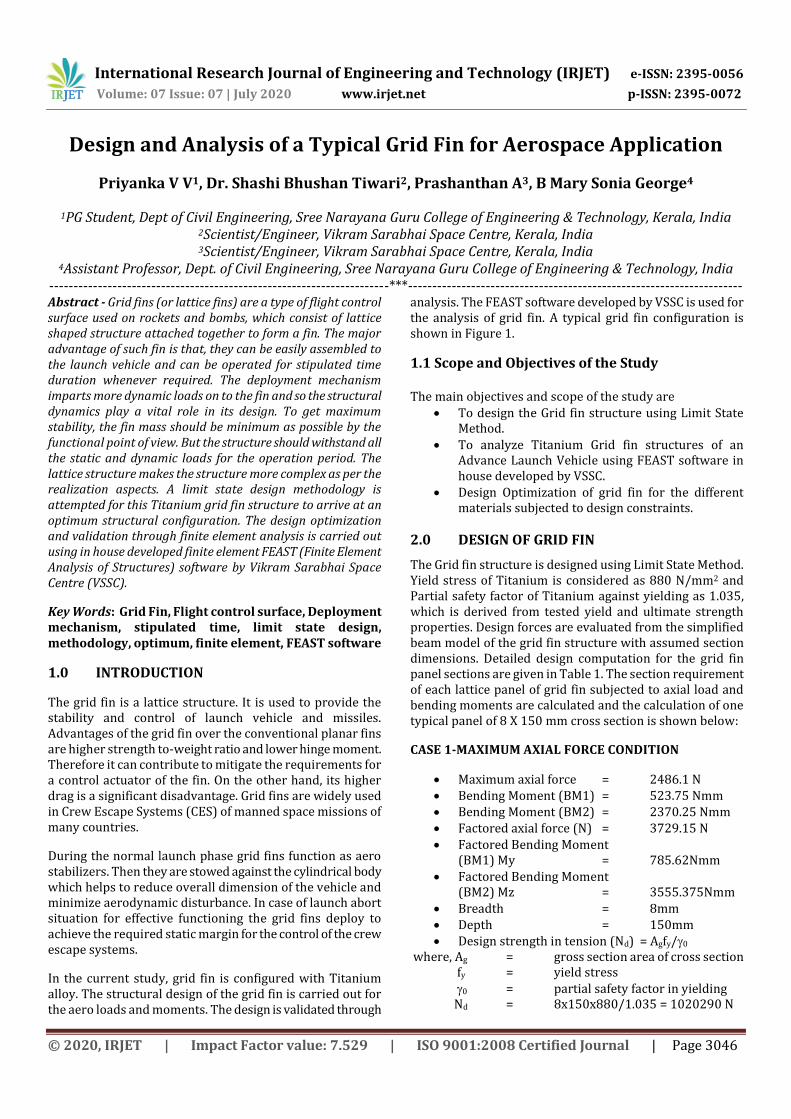
analysis. The FEAST software developed by VSSC is used for the analysis of grid fin. A typical grid fin configuration is shown in Figure 1.
1.1 Scope and Objectives of the Study The main objectives and scope of the study are
To design the Grid fin structure using Limit State Method.
To analyze Titanium Grid fin structures of an Advance Launch Vehicle using FEAST software in house developed by VSSC.
Design Optimization of grid fin for the different materials subjected to design constraints.
2.0 DESIGN OF GRID FIN
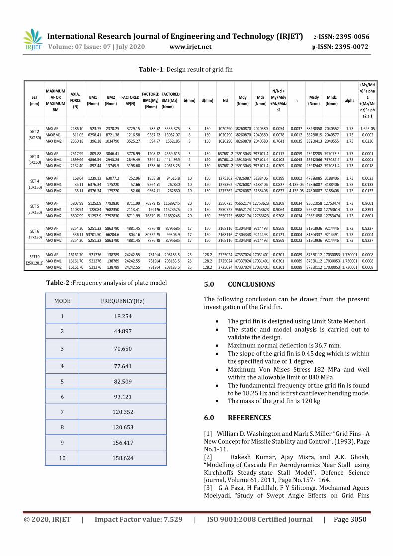
The Grid fin structure is designed using Limit State Method. Yield stress of Titanium is considered as 880 N/mm2 and Partial safety factor of Titanium against yielding as 1.035, which is derived from tested yield and ultimate strength properties. Design forces are evaluated from the simplified beam model of the grid fin structure with assumed section dimensions. Detailed design computation for the grid fin panel sections are given in Table 1. The section requirement of each lattice panel of grid fin subjected to axial load and bending moments are calculated and the calculation of one typical panel of 8 X 150 mm cross section is shown below:
CASE 1-MAXIMUM AXIAL FORCE CONDITION
Maximum axial force = 2486.1 N Bending Moment (BM1) = 523.75 Nmm Bending Moment (BM2) = 2370.25 Nmm Factored axial force (N) = 3729.15 N Factored Bending Moment
(BM1) My = 785.62Nmm Factored Bending Moment
(BM2) Mz = 3555.375Nmm Breadth = 8mm Depth = 150mm Design strength in tension (Nd) = Agfy/0
where, Ag = gross section area of cross section fy = yield stress 0 = partial safety factor in yielding Nd = 8x150x880/1.035 = 1020290 N
International Research Journal of Engineering and Technology (IRJET) e-ISSN: 2395-0056
Volume: 07 Issue: 07 | July 2020 www.irjet.net p-ISSN: 2395-0072
© 2020, IRJET | Impact Factor value: 7.529 | ISO 9001:2008 Certified Journal | Page 3047
Design strength under corresponding moment alone (Mdy,Mdz)
Mdy=βb*Zp*fy/0 = 1x8x1502x880/(4x1.035) = 38260870 Nmm Mdz=βb*Zp*fy/0 = 1x150x82x880/(4x1.035) = 2040580 Nmm
where ,βb = 1 ,for plastic and compact section Zp =Plastic section modulus of Cross section fy = Yield stress of material
0 = Partial safety factor Design reduced flexural strength under combined axial force and respective uniaxial moment acting alone(Mndy,Mndz)
Mndy = Mdy(1-n2)=38260870(1-0.003652) = 38260358 Nmm
, Mndz = Mdz(1-n2)= 2040580(1-0.003652) = 2040552 Nmm where, n=N/Nd
Design Check1 In the design of members subjected to combined axial force (tension or compression) and bending moment, the following should be satisfied:
(My/Mndy)α1 +(Mz/Mndz)α2 ≤ 1 where, My = Factored Bending Moment Mndy = Design reduced flexural strength under combined axial force and uniaxial moment acting alone
α1 = for solid rectangle=1.73+1.8n3
Mz = Factored Bending Moment Mndz = Design reduced flexural strength under combined axial force and respective uniaxial moment acting alone. α2 = for solid rectangle=1.73+1.8n3
(My/Mndy)α1 +(Mz/Mndz)α2 ≤ 1 (785.62/38260358)1.73 +(3555.375/2040552)(1.73) = 1.69E-5 ≤1
Hence the design check is satisfied, section is safe. Design Check 2 Conservatively, the following equation may also be used under combined axial force and bending moment
N/Nd + My/Mdy +Mz/Mdz ≤1
Where N = Factored axial force Nd = Design strength in tension My = Factored Bending Moment Mdy = Design strength under corresponding moment alone Mz = Factored Bending Moment
Mdz = Design strength under corresponding moment alone
N/Nd + My/Mdy +Mz/Mdz ≤1 (2729.15/1020290)+(785.62/38260870)+(3555.375/2040580)=0.0054≤1
Hence the design check is verified. Similarly design verification for maximum bending moment BM1 and BM2 conditions are also completed to check the design adequacy of the section dimensions.
CASE 2 -MAXIMUM BENDING MOMENT (BM1)
Axial force = 811.05 N
Bending Moment (BM1) = 6258.41 Nmm
Bending Moment (BM2) = 8721.38 Nmm
Factored axial force = 1216.58 N
Factored Bending Moment (BM1) = 9387.62 Nmm
Factored Bending Moment (BM2) = 13082.07 Nmm
Breadth(b) = 8 mm
Depth (d) = 150 mm
Design strength in tension (Nd) = 1020290 N
Mdy = 38260870 Nmm
Mdz = 2040580 Nmm
Mndy = 38260815 Nmm
Mndz = 2040577 Nmm
n = 0.0012
α2 = 1.73
α1 = 1.73
DESIGN CHECKS
Design Check1
(My/Mndy)α1 +(Mz/Mndz)α2 ≤ 1 (9387.62/38260815)(1.73) +(13082.07/2040577) (1.73)
= 0.0002 ≤1 Hence design check is verified. Design Check2
N/Nd + My/Mdy +Mz/Mdz ≤1
(1216.58/1020290)+(9387.62/38260870) +(13082.07/2040580) = 0.0078≤1
Hence the design check is satisfied, section is safe. CASE 3 - MAXIMUM BENDING MOMENT (BM2)
Axial force = 2350.18 N
Bending Moment (BM1) = 396.38 Nmm
International Research Journal of Engineering and Technology (IRJET) e-ISSN: 2395-0056
Volume: 07 Issue: 07 | July 2020 www.irjet.net p-ISSN: 2395-0072
© 2020, IRJET | Impact Factor value: 7.529 | ISO 9001:2008 Certified Journal | Page 3048
Bending Moment (BM2 = 1034790 Nmm
Factored axial force = 594.57 N
Factored Bending Moment (BM1) = 594.57 Nmm
Factored Bending Moment (BM2) = 1552185 Nmm
Breadth(b) = 8 mm
Depth (d) = 150 mm
Design strength in tension (Nd) = 1020290 N
Mdy = 38260870 Nmm
Mdz = 2040580 Nmm
Mndy = 38260413 Nmm
Mndz = 2040555Nmm
n = 0.0035
α2 = 1.73
α1 = 1.73
DESIGN CHECKS
DESIGN CHECK1
(My/Mndy)α1 +(Mz/Mndz)α2 ≤ 1 (594.57/38260413)(1.73) +(1552185/2040555)(1.73) =0.6230 ≤ 1 Hence design is verified.
DESIGN CHECK 2
N/Nd + My/Mdy +Mz/Mdz ≤ 1
(3525.27/1020290) + (594.57/38260870) + (1552185/2040580) = 0.7641 ≤ 1
Hence section of lattice panel taken is adequate.
3.0 ANALYSIS OF GRID FIN
3.1 Finite Element Modelling
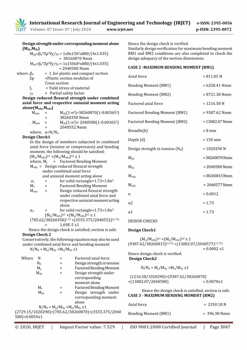
Grid fin of size 1992 mm x 1459 mm x 150 mm along with damper was modelled using FEAST software. The grid fin is idealized with general plate shell element. The grid fin interface bracket is modeled using 3 –D solid element. The grid fin is connected to the bracket at bolt locations using beam element. Damper is modelled as spring element and connected to the grid fin through a lug joint. Material properties of Titanium (Ti6Al4V) are used for the grid fin and interface brackets. Interface fasteners are of A286 property class high strength steel. Displacement boundary conditions ( Ux = Uy = Uz = 0) are specified at one end of the
damper and at bracket interface locations. The finite element model is shown in Figure 2. Aerodynamic forces are specified as distributed loads on all nodes of the grid fin. Linear Static and modal dynamic analyses were performed to estimate stress and deflection patterns and frequencies and associated mode shapes.
Fig - 1: Typical Grid Fin
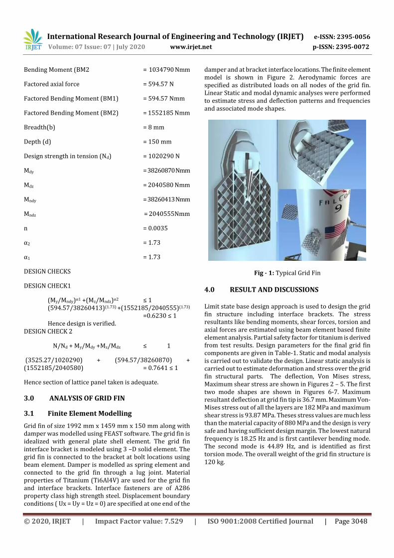
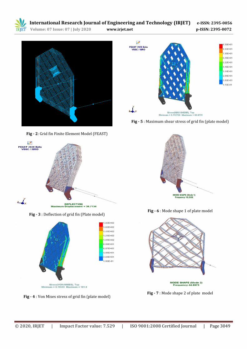
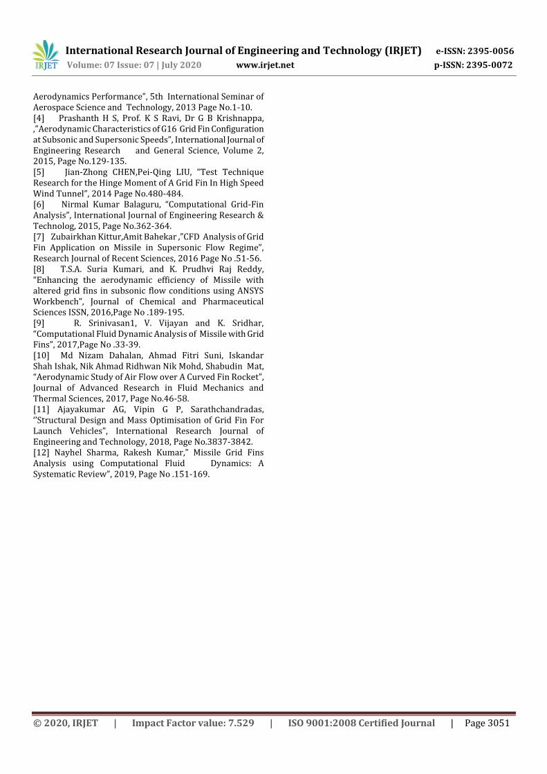
4.0 RESULT AND DISCUSSIONS Limit state base design approach is used to design the grid fin structure including interface brackets. The stress resultants like bending moments, shear forces, torsion and axial forces are estimated using beam element based finite element analysis. Partial safety factor for titanium is derived from test results. Design parameters for the final grid fin components are given in Table-1. Static and modal analysis is carried out to validate the design. Linear static analysis is carried out to estimate deformation and stress over the grid fin structural parts. The deflection, Von Mises stress, Maximum shear stress are shown in Figures 2 – 5. The first two mode shapes are shown in Figures 6-7. Maximum resultant deflection at grid fin tip is 36.7 mm. Maximum Von-Mises stress out of all the layers are 182 MPa and maximum shear stress is 93.87 MPa. Theses stress values are much less than the material capacity of 880 MPa and the design is very safe and having sufficient design margin. The lowest natural frequency is 18.25 Hz and is first cantilever bending mode. The second mode is 44.89 Hz, and is identified as first torsion mode. The overall weight of the grid fin structure is 120 kg.
International Research Journal of Engineering and Technology (IRJET) e-ISSN: 2395-0056
Volume: 07 Issue: 07 | July 2020 www.irjet.net p-ISSN: 2395-0072
© 2020, IRJET | Impact Factor value: 7.529 | ISO 9001:2008 Certified Journal | Page 3049
Fig - 2: Grid fin Finite Element Model (FEAST)
Fig - 3 : Deflection of grid fin (Plate model)
Fig - 4 : Von Mises stress of grid fin (plate model)
Fig - 5 : Maximum shear stress of grid fin (plate model)
Fig - 6 : Mode shape 1 of plate model
Fig - 7 : Mode shape 2 of plate model
International Research Journal of Engineering and Technology (IRJET) e-ISSN: 2395-0056
Volume: 07 Issue: 07 | July 2020 www.irjet.net p-ISSN: 2395-0072
© 2020, IRJET | Impact Factor value: 7.529 | ISO 9001:2008 Certified Journal | Page 3050
Table -1: Design result of grid fin
SET
(mm)
MAXIMUM
AF OR
MAXIMUM
BM
AXIAL
FORCE
(N)
BM1
(Nmm)
BM2
(Nmm)
FACTORED
AF(N)
FACTORED
BM1(My)
(Nmm)
FACTORED
BM2(Mz)
(Nmm)
b(mm) d(mm) NdMdy
(Nmm)
Mdz
(Nmm)
N/Nd +
My/Mdy
+Mz/Mdz
≤1
nMndy
(Nmm)
Mndz
(Nmm)alpha
(My/Md
y)^alpha
1
+(Mz/Mn
dz)^alph
a2 ≤ 1
MAX AF 2486.10 523.75 2370.25 3729.15 785.62 3555.375 8 150 1020290 38260870 2040580 0.0054 0.0037 38260358 2040552 1.73 1.69E-05
MAXBM1 811.05 6258.41 8721.38 1216.58 9387.62 13082.07 8 150 1020290 38260870 2040580 0.0078 0.0012 38260815 2040577 1.73 0.0002
MAX BM2 2350.18 396.38 1034790 3525.27 594.57 1552185 8 150 1020290 38260870 2040580 0.7641 0.0035 38260413 2040555 1.73 0.6230
MAX AF 2517.99 805.88 3046.41 3776.99 1208.82 4569.615 5 150 637681.2 23913043 797101.4 0.0117 0.0059 23912205 797073.5 1.73 0.0001
MAX BM1 1899.66 4896.54 2943.29 2849.49 7344.81 4414.935 5 150 637681.2 23913043 797101.4 0.0103 0.0045 23912566 797085.5 1.73 0.0001
MAX BM2 2132.40 892.44 13745.5 3198.60 1338.66 20618.25 5 150 637681.2 23913043 797101.4 0.0309 0.0050 23912442 797081.4 1.73 0.0018
MAX AF 168.64 1239.12 63077.2 252.96 1858.68 94615.8 10 150 1275362 47826087 3188406 0.0299 0.0002 47826085 3188406 1.73 0.0023
MAX BM1 35.11 6376.34 175220 52.66 9564.51 262830 10 150 1275362 47826087 3188406 0.0827 4.13E-05 47826087 3188406 1.73 0.0133
MAX BM2 35.11 6376.34 175220 52.66 9564.51 262830 10 150 1275362 47826087 3188406 0.0827 4.13E-05 47826087 3188406 1.73 0.0133
MAX AF 5807.99 51252.9 7792830 8711.99 76879.35 11689245 20 150 2550725 95652174 12753623 0.9208 0.0034 95651058 12753474 1.73 0.8601
MAX BM1 1408.94 128084 7682350 2113.41 192126 11523525 20 150 2550725 95652174 12753623 0.9064 0.0008 95652108 12753614 1.73 0.8391
MAX BM2 5807.99 51252.9 7792830 8711.99 76879.35 11689245 20 150 2550725 95652174 12753623 0.9208 0.0034 95651058 12753474 1.73 0.8601
MAX AF 3254.30 5251.32 5863790 4881.45 7876.98 8795685 17 150 2168116 81304348 9214493 0.9569 0.0023 81303936 9214446 1.73 0.9227
MAX BM1 536.11 53701.50 66204.6 804.16 80552.25 99306.9 17 150 2168116 81304348 9214493 0.0121 0.0004 81304337 9214491 1.73 0.0004
MAX BM2 3254.30 5251.32 5863790 4881.45 7876.98 8795685 17 150 2168116 81304348 9214493 0.9569 0.0023 81303936 9214446 1.73 0.9227
MAX AF 16161.70 521276 138789 24242.55 781914 208183.5 25 128.2 2725024 87337024 17031401 0.0301 0.0089 87330112 17030053 1.730001 0.0008
MAX BM1 16161.70 521276 138789 24242.55 781914 208183.5 25 128.2 2725024 87337024 17031401 0.0301 0.0089 87330112 17030053 1.730001 0.0008
MAX BM2 16161.70 521276 138789 24242.55 781914 208183.5 25 128.2 2725024 87337024 17031401 0.0301 0.0089 87330112 17030053 1.730001 0.0008
SET 3
(5X150)
SET 4
(10X150)
SET 5
(20X150)
SET 6
(17X150)
SET10
(25X128.2)
SET 2
(8X150)
Table-2 :Frequency analysis of plate model
5.0 CONCLUSIONS
The following conclusion can be drawn from the present investigation of the Grid fin.
The grid fin is designed using Limit State Method. The static and model analysis is carried out to
validate the design. Maximum normal deflection is 36.7 mm. The slope of the grid fin is 0.45 deg which is within
the specified value of 1 degree. Maximum Von Mises Stress 182 MPa and well
within the allowable limit of 880 MPa The fundamental frequency of the grid fin is found
to be 18.25 Hz and is first cantilever bending mode. The mass of the grid fin is 120 kg
6.0 REFERENCES [1] William D. Washington and Mark S. Miller “Grid Fins - A New Concept for Missile Stability and Control”, (1993), Page No.1-11. [2] Rakesh Kumar, Ajay Misra, and A.K. Ghosh, “Modelling of Cascade Fin Aerodynamics Near Stall using Kirchhoffs Steady-state Stall Model”, Defence Science Journal, Volume 61, 2011, Page No.157- 164. [3] G A Faza, H Fadillah, F Y Silitonga, Mochamad Agoes Moelyadi, “Study of Swept Angle Effects on Grid Fins
MODE FREQUENCY(Hz)
1 18.254
2 44.897
3 70.650
4 77.641
5 82.509
6 93.421
7 120.352
8 120.653
9 156.417
10 158.624
International Research Journal of Engineering and Technology (IRJET) e-ISSN: 2395-0056
Volume: 07 Issue: 07 | July 2020 www.irjet.net p-ISSN: 2395-0072
© 2020, IRJET | Impact Factor value: 7.529 | ISO 9001:2008 Certified Journal | Page 3051
Aerodynamics Performance”, 5th International Seminar of Aerospace Science and Technology, 2013 Page No.1-10. [4] Prashanth H S, Prof. K S Ravi, Dr G B Krishnappa, ,”Aerodynamic Characteristics of G16 Grid Fin Configuration at Subsonic and Supersonic Speeds”, International Journal of Engineering Research and General Science, Volume 2, 2015, Page No.129-135. [5] Jian-Zhong CHEN,Pei-Qing LIU, “Test Technique Research for the Hinge Moment of A Grid Fin In High Speed Wind Tunnel”, 2014 Page No.480-484. [6] Nirmal Kumar Balaguru, “Computational Grid-Fin Analysis”, International Journal of Engineering Research & Technolog, 2015, Page No.362-364. [7] Zubairkhan Kittur,Amit Bahekar ,”CFD Analysis of Grid Fin Application on Missile in Supersonic Flow Regime”, Research Journal of Recent Sciences, 2016 Page No .51-56. [8] T.S.A. Suria Kumari, and K. Prudhvi Raj Reddy, “Enhancing the aerodynamic efficiency of Missile with altered grid fins in subsonic flow conditions using ANSYS Workbench”, Journal of Chemical and Pharmaceutical Sciences ISSN, 2016,Page No .189-195. [9] R. Srinivasan1, V. Vijayan and K. Sridhar, “Computational Fluid Dynamic Analysis of Missile with Grid Fins”, 2017,Page No .33-39. [10] Md Nizam Dahalan, Ahmad Fitri Suni, Iskandar Shah Ishak, Nik Ahmad Ridhwan Nik Mohd, Shabudin Mat, “Aerodynamic Study of Air Flow over A Curved Fin Rocket”, Journal of Advanced Research in Fluid Mechanics and Thermal Sciences, 2017, Page No.46-58. [11] Ajayakumar AG, Vipin G P, Sarathchandradas, ‘’Structural Design and Mass Optimisation of Grid Fin For Launch Vehicles”, International Research Journal of Engineering and Technology, 2018, Page No.3837-3842. [12] Nayhel Sharma, Rakesh Kumar,” Missile Grid Fins Analysis using Computational Fluid Dynamics: A Systematic Review”, 2019, Page No .151-169.


