Embed Size (px)
Citation preview
International Research Journal of Engineering and Technology (IRJET) e-ISSN: 2395-0056
Volume: 07 Issue: 05 | May 2020 www.irjet.net p-ISSN: 2395-0072
© 2020, IRJET | Impact Factor value: 7.529 | ISO 9001:2008 Certified Journal | Page 501
Design & Feasibility Analysis of Ultra-filtration Tertiary Treatment
Plant to Generate Industrial Grade Water under Amrut Mission at Navi
Mumbai, Maharashtra.
Swapnil S. Desai1, 2, 3,
1Mechanical Engineer, Navi Mumbai Municipal Corporation, Navi Mumbai, Maharashtra, India. 2Managing Committee Member, Institution of Engineer India, BLC, Maharashtra.
3Senior Member, Indian Society of Mechanical Engineers, India. ---------------------------------------------------------------------***----------------------------------------------------------------------
Abstract - In Water sector water quality & water scarcity are the current issues. The use of membrane separation like ultra filtration for reuse of reclaimed water has become an increasingly attractive option. In this study the design & feasibility analysis of proposed project for recycling / reuse of wastewater are carried out. The main purpose of this paper was modeling and simulation of secondary treated water from 87.5 MLD capacity Sewage Treatment plant located at Koperkhairane, Navi Mumbai by Ultra filtration membrane Technology. The proposed UF tertiary treatment plant has a 20 MLD capacity which will produce the industrial grade water. In this study, a design method based on a simulation technique has been developed for optimizing UF systems. For proposed plant, DuPont WAVE design software version 1.72 is utilized to get detailed design. The statistical analysis is done & mathematical model gives detail of process parameters & optimum solution to produce the required quality tertiary treated water. The product water (tertiary treated water) obtained from Ultra filtration at a pressure of 1.2 MPa showed rejections of approximately 99.5 % for Turbidity, 100 % for TSS, 10 % for TOC. It also reduces the colloidal matter from feed water & achieves the SDI value less than 2.5 which meet the feed water quality of RO system in future. From detail design it will shows that, this proposed project is technically & financially feasible solution for Navi Mumbai Municipal Corporation (NMMC) to produce the industrial grade water & it will meet the desired tertiary quality parameters of state industrial development corporation (MIDC). Tertiary treated water is then providing to nearby industries for their industrial applications. UF is an excellent alternative for fresh water being supplied to industries & conserve the drinking water supply within the city.
Key Words: Ultra-filtration System, SBR C Tech, Simulation, CEB, CIP, Wave.
1. INTRODUCTION Water scarcity & availability of adequate water supply are the key issues in most of the Indian cities and town. As most of the cities has growing populations & it is insufficient to meet its water demand. The per capita water availability has dropped from 1816 cubic meter from 2001 to 1545 cubic meter in 2011 & it is further dropped to 1486 cubic meter in the years 2021 [1].From coming years there is increasing
water demand for household, industries and power plants and added stress on urban water infrastructure [2]. To mitigate such crises there is need for alternative to fresh water. Adequate collection of urban wastewater, its treatment and innovative technology implementation for reuse & recycle of treated wastewater or reclaimed water are such alternative which is gaining revenue. In some of the Indian cities, treated wastewater is practiced for industrial & other non potable use. Discharge of untreated sewage is the most important water pollutant source in India. Total sewage generated in urban area is 61948 MLD and total installed capacity is 23277 MLD [3]. In these urban areas, installed wastewater treatment capacity amount to only 37 % of wastewater generated. Around 63 % of wastewater generated from urban areas & 90% of wastewater generated from class II town in India is not treated & therefore its leads to environmental pollution. If such a large potential of wastewater is not treated then it is unavailable for other safe uses. Considering the current 1.7 % annum population growth & 3 % per decade of current urbanization rate, the urban population is expected to increase of around 590 million by 2030 [MGI 2010],with a proportionate volume of wastewater of 60000 MLD. If 80 % of this urban wastewater is treated, around 17 billion per year wastewater resources is generated. If these 17 BCM is captured, treated safely & recycle, this will meet the almost 75 % of projected industrial demand in 225 [MoWR 2006] and almost 25 % of total projected drinking water requirement in the country [2].
2. CITY SEWERAGE INFRASTRUCTURE The proposed project is at Navi Mumbai, Maharashtra. Navi Mumbai City is divided into 8 wards with a sewer network of 608 km, 21 nos of sewage pumping stations (SPS) & 7 nos of sewage treatment plants (STP) which are based on cyclic activated sludge (SBR C- tech) technology. Total installed capacity of SPS has 211 MLD & that of STP has 454 MLD. At present 210 MLD raw sewage is being treated. NMMC has plan to proposed Tertiary treatment Plant of 20 MLD capacity to generate industrial grade water for nearby industries in Navi Mumbai area. This project facilitates recycling of wastewater, an environmentally sound and progressive practice. It assures more stability in level of water supply to industrial units by providing supplementary source of water in addition to drinking water.
International Research Journal of Engineering and Technology (IRJET) e-ISSN: 2395-0056
Volume: 07 Issue: 05 | May 2020 www.irjet.net p-ISSN: 2395-0072
© 2020, IRJET | Impact Factor value: 7.529 | ISO 9001:2008 Certified Journal | Page 502
3. OBJECTIVES OF THE STUDY To check the feasibility & sustainability of tertiary treatment project. To stabilize the organic matter. To produce industrial grade water. To reclaim or reuse of treated wastewater for non potable use.
4. A REVIEW OF WASTEWATER TREATMENT BY MEMBRANE FILTRATION Membrane filtration has no of advantages compared to traditional separation technologies such as coagulation, aggregation, and sedimentation. It includes excellent quality of processed water, ease of maintenance, modular in nature, easy to operate, and convenience to control. Due to these advantages, membranes have been used for sewage treatment, wastewater treatment, seawater desalination, and drinking water production [4]. For proposed plant at Navi Mumbai, the technology selected is based on secondary water analysis & treated water quality which is required for TTC industrial area at Navi Mumbai, its techno- commercial feasibility study, assessment of demand etc. Based on secondary SBR treated water from existing STP, its analysis is carried out. Based on all above consideration, Ultra-filtration membrane based technology is selected which will give the desired quality as per the requirement of TTC area in Navi Mumbai. UF is a pressure-driven process which removes colloids, suspended solid, particulates, and high molecular mass soluble species. It is a single process which removes many organic as well as microbiological contaminants [8]. UF effectively removes protozoa, bacteria & most of the viruses and produces the disinfected filtrate quality with a little load on post treatment such as UV or ozone or even in chlorination. The removal of suspended solids (measured as a percentage of the feed concentration) of UF is at least 99%.The removal of microorganisms is referred to in log units. A removal of one log unit corresponds to a 90% removal & 4 log units correspond to a 99.99% removal. Following table shows the removal capacity of UF for different microorganisms.
Source- Water treatment: Principles and design, MWH
(2005), (ISBN 0 471 11018 3)
5. PROCESS DESCRIPTION
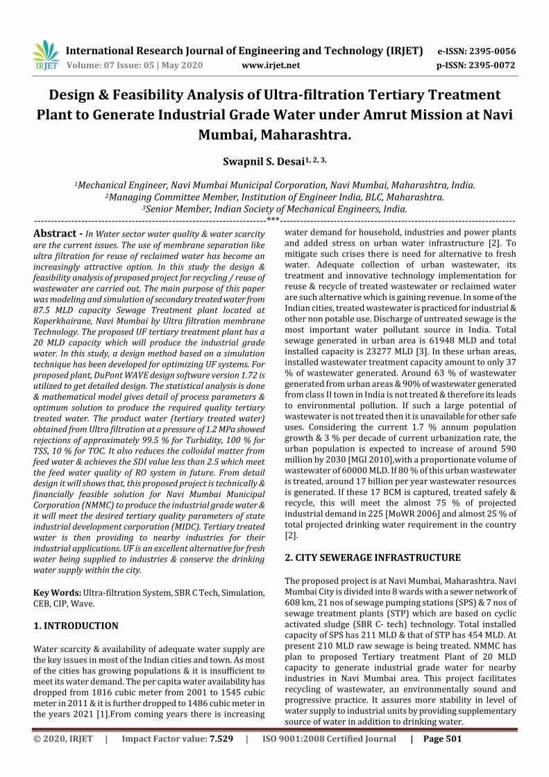
5.1 Principle The membrane is a semi permeable thin layer which separates the contaminants depending upon their physical & chemical characteristics. it will only allow certain compounds to pass through it. Membrane size & chemical characteristics determines material that will pass through it [6].The pore size determines the removal of different compounds. In membrane separation processes, the feed is separated into a stream, the permeate that goes through the membrane, and the retentate or the concentrate (a fraction of feed that does not go through the membrane).A membrane process then allows selective and controlled transfer of one species from one bulk phase to another bulk phase separated by the membrane [5].
Feed Permeate Qf Cf Pf Qp Cp Pp Concentrate Qc Cc Pc
Fig -1: Metcalf & eddy/membrane filtration process
5.2 Membrane Module In the membrane field the module is used to describe a complete unit comprised of the membranes, the pressure support structure for the membrane, the feed inlet and outlet permeate & retentate ports and an overall support structure.(Metcalf & eddy 11.6) there are different types of module are used for wastewater treatment. Principle types are tubular, hallow fiber, spiral wound. Plate & frame and pleated cartridge filters are also available but more commonly used in industrial applications. For these study spiral wound UF module from DuPont are used.
5.3 Membrane Operation In the membrane operation pump is used to pressurize the feed water and to circulate it into water. The valve is used to maintain the pressure on reject side. The permeate is withdrawal at atmospheric pressure. As the impurities or constituents are accumulating on the membrane (Membrane fouling), the pressure is built-up on the feed side, & the membrane flux is start decline, also percent rejection start declines. When the performance has deteriorated to a given level, the membrane, module is taken out for backwash or cleaned chemically. (CEB/CIP)
5.4 Kinetics For the UF installations Flux is the most important parameter. It is nothing but the water flow through a square meter of membrane surface. J = (Q/A mean) = TMP/ (V. Ttot)
International Research Journal of Engineering and Technology (IRJET) e-ISSN: 2395-0056
Volume: 07 Issue: 05 | May 2020 www.irjet.net p-ISSN: 2395-0072
© 2020, IRJET | Impact Factor value: 7.529 | ISO 9001:2008 Certified Journal | Page 503
Where J is flux (m3/m2.s), Q is volume flux (m3/h), Amem is membrane surface area (m2), TMP is trans-membrane pressure (Pa), v is dynamic viscosity (Pa/s) & Rtot is total resistance (m). Water passes through the membrane under the influence of pressure. The pressure difference across the membrane is called Trans Membrane Pressure (TMP). The temperature of the water influences the flux at a certain TMP. Each degree of temperature (ºC) increase gives 3% more flux at the same pressure. For the cross flow mode of operation the TMP is given by,
Ptm = Pf – (⩟Phydr/ 2) - Pp The hydraulic pressure loss in an ultra-filtration module is small and can be ignored. The permeate pressure needed to transport the permeate is rather small (0.1 bar). The pressure on the feed side of the UF membrane is typically 0.5 bar. So rearranging the equation
Ptm = (Pf –Pc /2) - Pp Where Ptm is TMP, Pf, Pc Pp are pressure of feed, concentrate & permeate stream in KPa. The overall pressure drop across the module is given by,
P = Pf- Pp The total permeate flow from a membrane system is given by,
Qp = Fw A Where, Fw is the trance membrane water flux rate, Kg/m2.s it is a function of quality of feed stream, degree of pretreatment, characteristics of membrane and system operating parameters The recovery rate r (refers to the water) is defines as
r % = Qp/Qf x 100 Where, Qp & Qf are permeate & feed stream respectively, Kg/s. In order to achieve a high recovery (>90%), the filtration period should be extended and the backwash should be carried out with a minimum amount of permeate. Rate of rejection (refers to the solute) is define as
R % = (Cf- Cp/2) x 100 The corresponding mass balance equations are,
Qf = Qp + Qc Qf Cf = Qp Cp + Qc Cp
6. METHODOLOGY
6.1 Secondary Municipal Effluent The Navi Mumbai Municipal Corporation has 6 STP’s of total 454 MLD capacity based on Cyclic activated sludge Tech (C-Tech). The proposed project is located at Koperkhairane STP which is 87.5 MLD capacity. It has 6 Nos of SBR C Tech basin with an aerobic biological treatment process. It is suspended growth process similar to ASP or extended aeration. The waste is degraded by biomass (bacteria & other living organism) that is feed on the waste. It is a batch process where aeration, settling/clarification happen in a single tank. It has a four cycle’s e.g. filling, aeration, settling & decanting. The sludge disposal is performed by centrifuge decanters & disposed to landfill. The secondary effluents sample was
collected from STP over a period of 3 months. The main quality parameters of the secondary effluent are as follows,
Table 1 Secondary effluents quality parameters
Parameters Unit Outlet* MAC ** pH mg/l 6.5-9 6.5-9.0 BOD mg/l ≤ 5.0 10 COD mg/l 20 50 TSS mg/l 10 20 Oil & grease mg/l BDL - NH3 mg/l 0.05 5 Nitrite Nitrogen
mg/l 18-20 10
P mg/l 0.20-0.30 2 S mg/l 0.02-0.05 - Chloride mg/l 3-4 - TDS mg/l 500-1200 - Total Coliform mg/l 130-160 - Fecal Coliform mg/l 15-25 ≤ 100
* The analyzed values column shows the range variation of the effluent samples collected during the experiments. ** = maximum acceptable concentration for discharge in water bodies as per CPCB guidelines.
The design of UF plant is carried out as per the guidelines of CPHEEO manual. To study the concept, feasibility & operational status, similar type of plants installed in different locations in India like, 40 MLD UF/RO at Dindoli, Surat, 20 MLD UF/RO plant at RCF Chembur, 10 MLD at CSIA Mumbai, & similar types of plants located at Chennai & Delhi are visited. While studying these plants, it is observed that reasonable and efficient pretreatment is the key point of a UF system. Most of feed water must be treated before flowing into the UF system. Here secondary treated sewage water is a feed to the UF plant. Here a filter of 150 um in size is installed before UF plant to reduce the organic load .The detail methodology & design of UF plant for secondary treated water at Koperkhairane, Navi Mumbai is as fallows,
6.2 Feed Water Analysis for UF System Feed water analysis is very important for the UF system design. The type of water resource, turbidity, suspended solids, COD and BOD, Ph, nutrients contains, TDS etc all have to be considered. Some other data, such as the types of organic pollutants, detail ionic contains (for reduction of scaling & fouling of membrane) and the contents of bacteria and viruses are also analyses. Proposed UF plant has secondary treated water from STP as feed water. The raw sewage & secondary treated sewage characteristics considered for the design is summarized as follows,
Table 2 UF Feed Water Analysis
Parameters Unit Result* TSS mg/l 20
International Research Journal of Engineering and Technology (IRJET) e-ISSN: 2395-0056
Volume: 07 Issue: 05 | May 2020 www.irjet.net p-ISSN: 2395-0072
© 2020, IRJET | Impact Factor value: 7.529 | ISO 9001:2008 Certified Journal | Page 504
PH mg/l 6.5-7.5 Turbidity mg/l 20 TOC mg/l 5 Bicarbonate HCO3 mg/l 0.42 Nitrate as NO3 mg/l 0.65 Sulphate as SO4 mg/l 12 Ammonia as NH3 mg/l 0.5 Fluroide mg/l 0.1 Chloride mg/l 80 Silica as Sio2 mg/l 0.6 METALS Calcium as Ca mg/l 35 Magnesium as Mg mg/l 13 Sodium as Na mg/l 112 Potassium as K mg/l 12 Boron as B mg/l 0.1 Stritium as Sr mg/l 0.05
* Protocol of analysis as per IS: 3025 & IS 1622:1981 Source –Report from Thans Thane Creek Waste Management Association
6.3 Expected UF treated water quality parameters The proposed tertiary treatment plant is designed to deliver the treated wastewater conforming to the standard specified by the Maharashtra industrial development corporation (MIDC). However, since the reject water shall have to be discharged in nearby Creek, the disposal parameters are considered with the nutrient and phosphate removal. The tertiary treated sewage characteristics considered for the design is summarized as follows,
Table 3 Expected UF Outlet Quality
Parameters Unit UF Product Water* BOD ≤ 5.0 COD ≤ 20.0 TSS ≤ 1.0 Turbidity ≤ 0.5 Total Nitrogen ( TN) ≤ 10.0 Ammonical Nitrogen ≤ 2.0 Total Kjehldal Nitrogen ≤ 5.0 DO > 2.0 Total Phosphorus ≤ 1.0 pH 7 -8.5 Free residual Chlorine 1-2 Bacteria ≥ log 5 reduction Viruses ≥ log 5 reduction Protozoa ≥ log 5 reduction Oil & grease ≤ 0.010 TDS ≤ 500
* As per NMMC Teder Documents NMMC/CE/ /2019-20
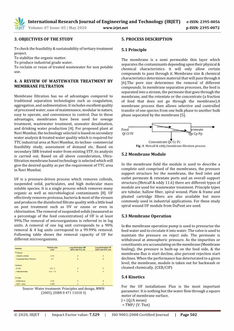
6.4 Selection of operation mode and the flux rate For the proposed project a cross flow mode of operation are selected to get the desired UF output. In Cross flow filtration flow is applied tangentially across the membrane surface. As
feed water flows across the membrane surface, filtrate passes through it & concentrate accumulates at the opposite end of the membrane. It creates a shearing effect on the surface of the membrane, which reduces fouling of membrane. It removes the build-up of constituents on the membrane surface & does not drops the permeate flux as fast when compared to dead end operation.
Fig -1: Source-synderfiltration.com/learning-
center/articles/module-configurations-process/cross-flow-
membrane-operations/
Flux rate is very important parameter of the membrane selection. For the membrane processes following design guidelines are followed.
Table 4 Flux rate
Type of Water Desired Limit Bore well Water Upto 60 LMH River Water Upto 65 LMH Treated Effluent Upto 30-35 LMH
Source-Wastewater Treatment & Recycling EA Water design
guidelines/29-30/2020
6.5 Selection of UF Module & number of modules There are different types of module available in the market but DuPont make UF Spiral wound module of IntegraPac IP-77 series are selected which are specifically used for municipal wastewater application. Generally UF systems are designed for a specified amount of water production per day (total permeate flow QT). Then a number of membrane elements (NE) required to produce QT is estimated from dividing QT by average permeate flow per element (QA),
Input data- Product Flow Required -20,000 M3/Day Effective surface membrane area – 51 m2 Average permeate flux = 40 LMH No Of Membrane elements required NE = Qt/Qa In most standard applications, the average permeates flow per element (Qa) is about 75 % of the maximum permeate flow per element (Qm), Qm = 0.75 % Qa
International Research Journal of Engineering and Technology (IRJET) e-ISSN: 2395-0056
Volume: 07 Issue: 05 | May 2020 www.irjet.net p-ISSN: 2395-0072
© 2020, IRJET | Impact Factor value: 7.529 | ISO 9001:2008 Certified Journal | Page 505
But to calculate more accurately, Average permeates flow per element Qa = S x F = 51 x (0.75% x 40) = 36.72 M3/Day So total no of module required for the UF plant, NE = 20000/ 36.72 = 545 = 550 Modules (by considering Standby Module) Filtrate Flux (25ºC) 40 – 90 l/m2hr Flow Range Per Module1 2.0 – 6.9 m3 /hr Temperature 1 – 40ºC Maximum Inlet Module Pressure 6.25 bar Maximum Inlet Module Pressure 4.75 bar Maximum Operating TMP 2.1 bar Maximum Operating Air Scour Flow 12 Nm3 /hr Maximum Backwash Pressure 2.5 bar Operating pH 2 -11 Flow Configuration Outside-in Expected Filtrate Turbidity ≤ 0.1 NTU Expected Filtrate SDI ≤ 2.5 Maximum NaOCl 2000 mg/l Maximum Particle size 300 um
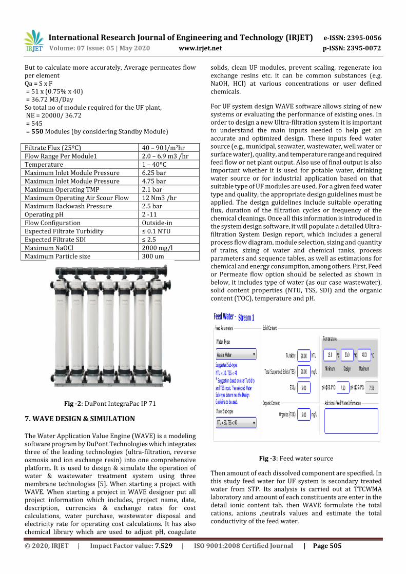
Fig -2: DuPont IntegraPac IP 71
7. WAVE DESIGN & SIMULATION The Water Application Value Engine (WAVE) is a modeling software program by DuPont Technologies which integrates three of the leading technologies (ultra-filtration, reverse osmosis and ion exchange resin) into one comprehensive platform. It is used to design & simulate the operation of water & wastewater treatment system using three membrane technologies [5]. When starting a project with WAVE. When starting a project in WAVE designer put all project information which includes, project name, date, description, currencies & exchange rates for cost calculations, water purchase, wastewater disposal and electricity rate for operating cost calculations. It has also chemical library which are used to adjust pH, coagulate
solids, clean UF modules, prevent scaling, regenerate ion exchange resins etc. it can be common substances (e.g. NaOH, HCl) at various concentrations or user defined chemicals.
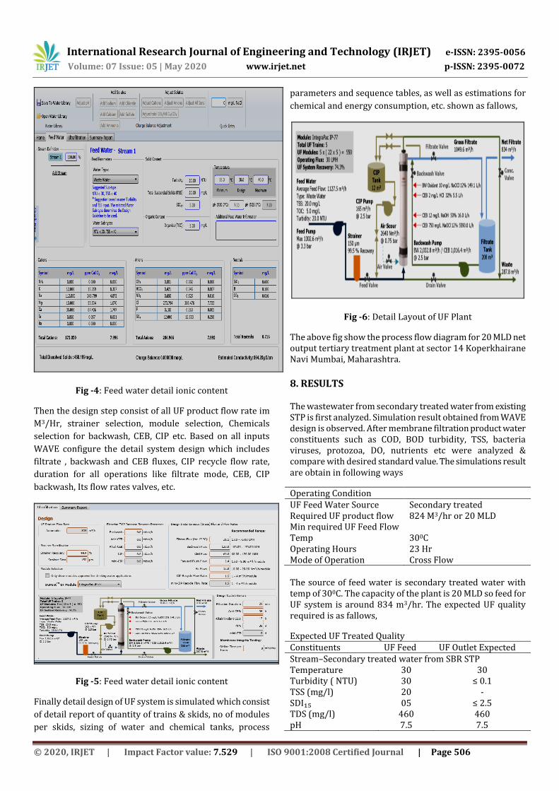
For UF system design WAVE software allows sizing of new systems or evaluating the performance of existing ones. In order to design a new Ultra-filtration system it is important to understand the main inputs needed to help get an accurate and optimized design. These inputs feed water source (e.g., municipal, seawater, wastewater, well water or surface water), quality, and temperature range and required feed flow or net plant output. Also use of final output is also important whether it is used for potable water, drinking water source or for industrial application based on that suitable type of UF modules are used. For a given feed water type and quality, the appropriate design guidelines must be applied. The design guidelines include suitable operating flux, duration of the filtration cycles or frequency of the chemical cleanings. Once all this information is introduced in the system design software, it will populate a detailed Ultra-filtration System Design report, which includes a general process flow diagram, module selection, sizing and quantity of trains, sizing of water and chemical tanks, process parameters and sequence tables, as well as estimations for chemical and energy consumption, among others. First, Feed or Permeate flow option should be selected as shown in below, it includes type of water (as our case wastewater), solid content properties (NTU, TSS, SDI) and the organic content (TOC), temperature and pH.
Fig -3: Feed water source
Then amount of each dissolved component are specified. In this study feed water for UF system is secondary treated water from STP. Its analysis is carried out at TTCWMA laboratory and amount of each constituents are enter in the detail ionic content tab. then WAVE formulate the total cations, anions ,neutrals values and estimate the total conductivity of the feed water.
International Research Journal of Engineering and Technology (IRJET) e-ISSN: 2395-0056
Volume: 07 Issue: 05 | May 2020 www.irjet.net p-ISSN: 2395-0072
© 2020, IRJET | Impact Factor value: 7.529 | ISO 9001:2008 Certified Journal | Page 506
Fig -4: Feed water detail ionic content
Then the design step consist of all UF product flow rate im
M3/Hr, strainer selection, module selection, Chemicals
selection for backwash, CEB, CIP etc. Based on all inputs
WAVE configure the detail system design which includes
filtrate , backwash and CEB fluxes, CIP recycle flow rate,
duration for all operations like filtrate mode, CEB, CIP
backwash, Its flow rates valves, etc.
Fig -5: Feed water detail ionic content
Finally detail design of UF system is simulated which consist
of detail report of quantity of trains & skids, no of modules
per skids, sizing of water and chemical tanks, process
parameters and sequence tables, as well as estimations for
chemical and energy consumption, etc. shown as fallows,
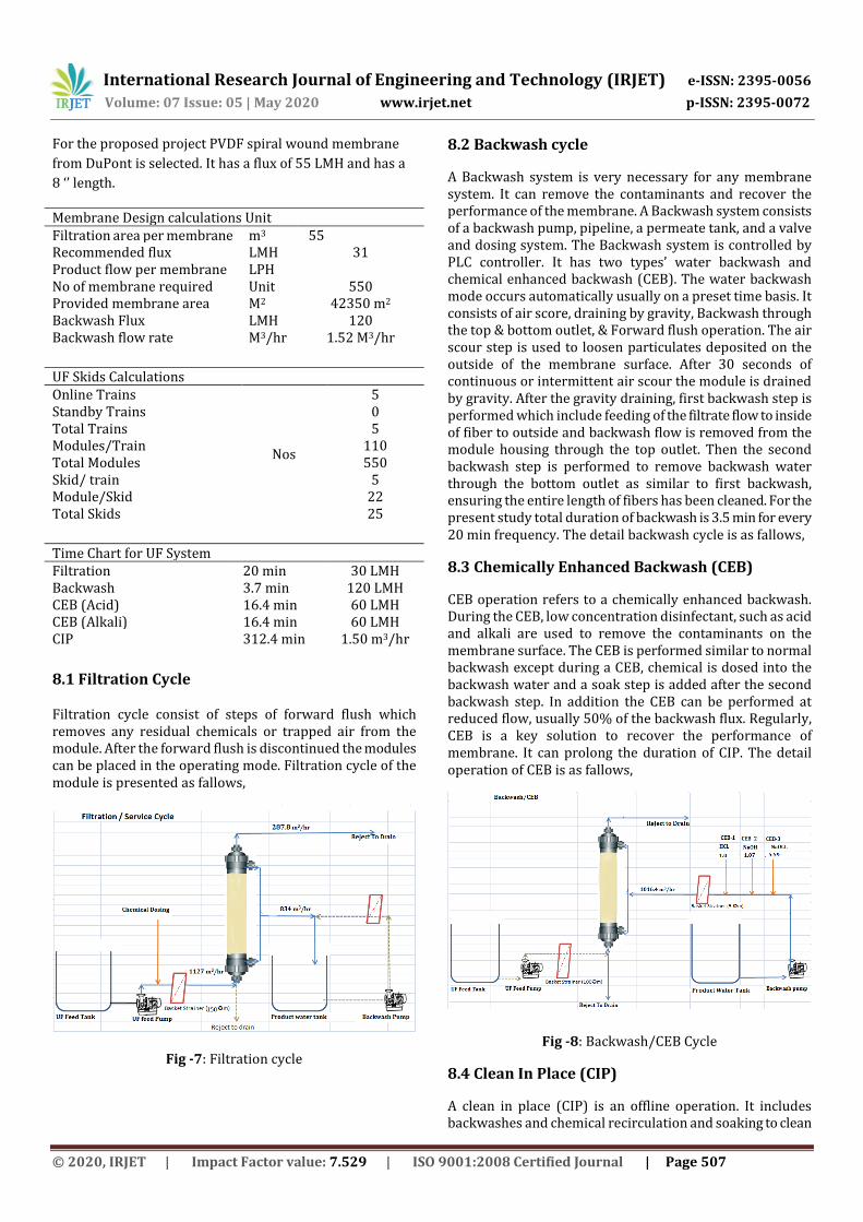
Fig -6: Detail Layout of UF Plant
The above fig show the process flow diagram for 20 MLD net output tertiary treatment plant at sector 14 Koperkhairane Navi Mumbai, Maharashtra.
8. RESULTS
The wastewater from secondary treated water from existing STP is first analyzed. Simulation result obtained from WAVE design is observed. After membrane filtration product water constituents such as COD, BOD turbidity, TSS, bacteria viruses, protozoa, DO, nutrients etc were analyzed & compare with desired standard value. The simulations result are obtain in following ways
Operating Condition UF Feed Water Source Secondary treated Required UF product flow 824 M3/hr or 20 MLD Min required UF Feed Flow Temp 300C Operating Hours 23 Hr Mode of Operation Cross Flow The source of feed water is secondary treated water with temp of 300C. The capacity of the plant is 20 MLD so feed for UF system is around 834 m3/hr. The expected UF quality required is as fallows,
Expected UF Treated Quality Constituents UF Feed UF Outlet Expected Stream–Secondary treated water from SBR STP Temperature 30 30 Turbidity ( NTU) 30 ≤ 0.1 TSS (mg/l) 20 - SDI₁₅ 05 ≤ 2.5 TDS (mg/l) 460 460 pH 7.5 7.5
International Research Journal of Engineering and Technology (IRJET) e-ISSN: 2395-0056
Volume: 07 Issue: 05 | May 2020 www.irjet.net p-ISSN: 2395-0072
© 2020, IRJET | Impact Factor value: 7.529 | ISO 9001:2008 Certified Journal | Page 507
For the proposed project PVDF spiral wound membrane
from DuPont is selected. It has a flux of 55 LMH and has a
8 ‘’ length.
Membrane Design calculations Unit Filtration area per membrane m3 55 Recommended flux LMH 31 Product flow per membrane LPH No of membrane required Unit 550 Provided membrane area M2 42350 m2 Backwash Flux LMH 120 Backwash flow rate M3/hr 1.52 M3/hr
UF Skids Calculations Online Trains
Nos
5 Standby Trains 0 Total Trains 5 Modules/Train 110 Total Modules 550 Skid/ train 5 Module/Skid 22 Total Skids 25
Time Chart for UF System Filtration 20 min 30 LMH Backwash 3.7 min 120 LMH CEB (Acid) 16.4 min 60 LMH CEB (Alkali) 16.4 min 60 LMH CIP 312.4 min 1.50 m3/hr
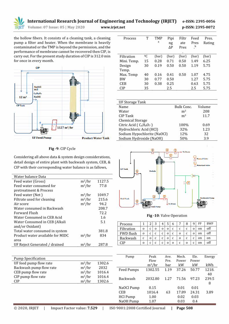
8.1 Filtration Cycle
Filtration cycle consist of steps of forward flush which removes any residual chemicals or trapped air from the module. After the forward flush is discontinued the modules can be placed in the operating mode. Filtration cycle of the module is presented as fallows,
Fig -7: Filtration cycle
8.2 Backwash cycle
A Backwash system is very necessary for any membrane system. It can remove the contaminants and recover the performance of the membrane. A Backwash system consists of a backwash pump, pipeline, a permeate tank, and a valve and dosing system. The Backwash system is controlled by PLC controller. It has two types’ water backwash and chemical enhanced backwash (CEB). The water backwash mode occurs automatically usually on a preset time basis. It consists of air score, draining by gravity, Backwash through the top & bottom outlet, & Forward flush operation. The air scour step is used to loosen particulates deposited on the outside of the membrane surface. After 30 seconds of continuous or intermittent air scour the module is drained by gravity. After the gravity draining, first backwash step is performed which include feeding of the filtrate flow to inside of fiber to outside and backwash flow is removed from the module housing through the top outlet. Then the second backwash step is performed to remove backwash water through the bottom outlet as similar to first backwash, ensuring the entire length of fibers has been cleaned. For the present study total duration of backwash is 3.5 min for every 20 min frequency. The detail backwash cycle is as fallows,
8.3 Chemically Enhanced Backwash (CEB)
CEB operation refers to a chemically enhanced backwash. During the CEB, low concentration disinfectant, such as acid and alkali are used to remove the contaminants on the membrane surface. The CEB is performed similar to normal backwash except during a CEB, chemical is dosed into the backwash water and a soak step is added after the second backwash step. In addition the CEB can be performed at reduced flow, usually 50% of the backwash flux. Regularly, CEB is a key solution to recover the performance of membrane. It can prolong the duration of CIP. The detail operation of CEB is as fallows,
Fig -8: Backwash/CEB Cycle
8.4 Clean In Place (CIP)
A clean in place (CIP) is an offline operation. It includes backwashes and chemical recirculation and soaking to clean
International Research Journal of Engineering and Technology (IRJET) e-ISSN: 2395-0056
Volume: 07 Issue: 05 | May 2020 www.irjet.net p-ISSN: 2395-0072
© 2020, IRJET | Impact Factor value: 7.529 | ISO 9001:2008 Certified Journal | Page 508
the hollow fibers. It consists of a cleaning tank, a cleaning pump a filter and heater. When the membrane is heavily contaminated or the TMP is beyond the permission, and the performance of membrane cannot be recovered then CIP, is carry out. For the present study duration of CIP is 312.0 min for once in every month.
Fig -9: CIP Cycle
Considering all above data & system design considerations,
detail design of entire plant with backwash system, CEB, &
CIP with their corresponding water balance is as fallows,
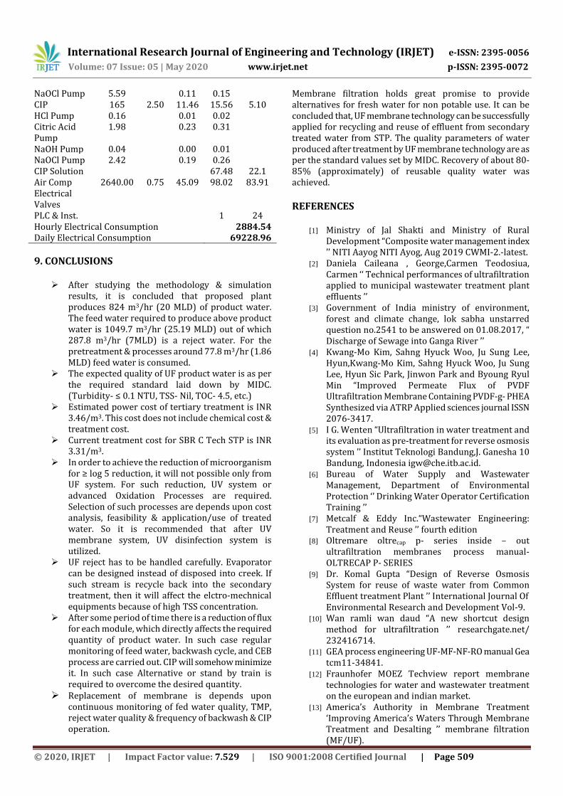
Water balance Data Feed water (Gross) m3/hr 1127.5 Feed water consumed for pretreatment & Process
m3/hr 77.8
Feed water (Net ) m3/hr 1049.7 Filtrate used for cleaning m3/hr 215.6 Air score m3/hr 94.2 Water consumed in Backwash 208.7 Forward Flush 72.2 Water Consumed in CEB Acid 1.6 Water Consumed in CEB (Alkali and/or Oxidant)
5.1
Total water consumed in system 381.8 Product water available for MIDC area
m3/hr 834
UF Reject Generated / drained m3/hr 287.8
Pump Specification UF feed pump flow rate m3/hr 1302.6 Backwash pump flow rate m3/hr 2032 CEB pump flow rate m3/hr 1016.4 CIP pump flow rate m3/hr 1016.4 CIP m3/hr 1302.6
Process T TMPᵃ
Piping ∆P
Filtrate
Pres.
Feed Pres
.ᵇ
Pres. Rating
Filtration 0C (bar) (bar) (bar) (bar) (bar)
Mini. Temp. 15 0.28 0.71 0.50 1.49 6.25 Design Temp.
30 0.19 0.50 0.50 1.19 5.75
Max. Temp 40 0.16 0.41 0.50 1.07 4.75 BW 30 0.77 0.50 1.27 5.75 CEB 30 0.38 0.25 0.63 5.75 CIP 35 2.5 2.5 5.75
UF Storage Tank Name Bulk Conc. Volume Water m3 208 CIP Tank m3 11.7 Chemical Storage Citric Acid ( C6H8O7 ) 100% 0.69 Hydrochloric Acid (HCl) 32% 1.23 Sodium Hypochlorite (NaOCl) 12% 32 Sodium Hydroxide (NaOH) 50% 3.9
Fig -10: Valve Operation
Process 1 2 3 4 5 6 7 8 9 FP BWP
Filtration o c o o o c c c o on off
FWD flush o c c c o c o c o on off
Backwash c o c c o c o c c on on
CIP o c c c o o c o c on off
Pump Peak Flow
Ave. Pre.
Mech. Power
Ele. Power
Energy
m3/hr bar kW kW kWh Feed Pumps 1302.55 1.19 37.26 50.77 1218.
40 Backwash 2032.80 1.27 71.56 97.23 239.5
8 NaOCl Pump 0.15 0.01 0.01 CEB 1016.4 63 17.89 24.31 3.89 HCl Pump 1.00 0.02 0.03 NaOH Pump 1.07 0.03 0.4
International Research Journal of Engineering and Technology (IRJET) e-ISSN: 2395-0056
Volume: 07 Issue: 05 | May 2020 www.irjet.net p-ISSN: 2395-0072
© 2020, IRJET | Impact Factor value: 7.529 | ISO 9001:2008 Certified Journal | Page 509
NaOCl Pump 5.59 0.11 0.15 CIP 165 2.50 11.46 15.56 5.10 HCl Pump 0.16 0.01 0.02 Citric Acid Pump
1.98 0.23 0.31
NaOH Pump 0.04 0.00 0.01 NaOCl Pump 2.42 0.19 0.26 CIP Solution 67.48 22.1 Air Comp 2640.00 0.75 45.09 98.02 83.91 Electrical Valves
PLC & Inst. 1 24 Hourly Electrical Consumption 2884.54 Daily Electrical Consumption 69228.96
9. CONCLUSIONS
After studying the methodology & simulation results, it is concluded that proposed plant produces 824 m3/hr (20 MLD) of product water. The feed water required to produce above product water is 1049.7 m3/hr (25.19 MLD) out of which 287.8 m3/hr (7MLD) is a reject water. For the pretreatment & processes around 77.8 m3/hr (1.86 MLD) feed water is consumed.
The expected quality of UF product water is as per the required standard laid down by MIDC. (Turbidity- ≤ 0.1 NTU, TSS- Nil, TOC- 4.5, etc.)
Estimated power cost of tertiary treatment is INR 3.46/m3. This cost does not include chemical cost & treatment cost.
Current treatment cost for SBR C Tech STP is INR 3.31/m3.
In order to achieve the reduction of microorganism for ≥ log 5 reduction, it will not possible only from UF system. For such reduction, UV system or advanced Oxidation Processes are required. Selection of such processes are depends upon cost analysis, feasibility & application/use of treated water. So it is recommended that after UV membrane system, UV disinfection system is utilized.
UF reject has to be handled carefully. Evaporator can be designed instead of disposed into creek. If such stream is recycle back into the secondary treatment, then it will affect the elctro-mechnical equipments because of high TSS concentration.
After some period of time there is a reduction of flux for each module, which directly affects the required quantity of product water. In such case regular monitoring of feed water, backwash cycle, and CEB process are carried out. CIP will somehow minimize it. In such case Alternative or stand by train is required to overcome the desired quantity.
Replacement of membrane is depends upon continuous monitoring of fed water quality, TMP, reject water quality & frequency of backwash & CIP operation.
Membrane filtration holds great promise to provide alternatives for fresh water for non potable use. It can be concluded that, UF membrane technology can be successfully applied for recycling and reuse of effluent from secondary treated water from STP. The quality parameters of water produced after treatment by UF membrane technology are as per the standard values set by MIDC. Recovery of about 80-85% (approximately) of reusable quality water was achieved.
REFERENCES
[1] Ministry of Jal Shakti and Ministry of Rural Development “Composite water management index ’’ NITI Aayog NITI Ayog, Aug 2019 CWMI-2.-latest.
[2] Daniela Caileana , George,Carmen Teodosiua, Carmen ‘‘ Technical performances of ultrafiltration applied to municipal wastewater treatment plant effluents ’’
[3] Government of India ministry of environment, forest and climate change, lok sabha unstarred question no.2541 to be answered on 01.08.2017, “ Discharge of Sewage into Ganga River ’’
[4] Kwang-Mo Kim, Sahng Hyuck Woo, Ju Sung Lee, Hyun,Kwang-Mo Kim, Sahng Hyuck Woo, Ju Sung Lee, Hyun Sic Park, Jinwon Park and Byoung Ryul Min “Improved Permeate Flux of PVDF Ultrafiltration Membrane Containing PVDF-g- PHEA Synthesized via ATRP Applied sciences journal ISSN 2076-3417.
[5] I G. Wenten “Ultrafiltration in water treatment and its evaluation as pre-treatment for reverse osmosis system ’’ Institut Teknologi Bandung,J. Ganesha 10 Bandung, Indonesia [email protected].
[6] Bureau of Water Supply and Wastewater Management, Department of Environmental Protection ‘’ Drinking Water Operator Certification Training ’’
[7] Metcalf & Eddy Inc.“Wastewater Engineering: Treatment and Reuse ’’ fourth edition
[8] Oltremare oltrecap p- series inside – out ultrafiltration membranes process manual- OLTRECAP P- SERIES
[9] Dr. Komal Gupta “Design of Reverse Osmosis System for reuse of waste water from Common Effluent treatment Plant ’’ International Journal Of Environmental Research and Development Vol-9.
[10] Wan ramli wan daud “A new shortcut design method for ultrafiltration ’’ researchgate.net/ 232416714.
[11] GEA process engineering UF-MF-NF-RO manual Gea tcm11-34841.
[12] Fraunhofer MOEZ Techview report membrane technologies for water and wastewater treatment on the european and indian market.
[13] America’s Authority in Membrane Treatment ‘Improving America’s Waters Through Membrane Treatment and Desalting ’’ membrane filtration (MF/UF).
International Research Journal of Engineering and Technology (IRJET) e-ISSN: 2395-0056
Volume: 07 Issue: 05 | May 2020 www.irjet.net p-ISSN: 2395-0072
© 2020, IRJET | Impact Factor value: 7.529 | ISO 9001:2008 Certified Journal | Page 510
[14] Ingo Pinnau, Ph.D. “Membranes for Water Treatment: Properties and Characterization Advanced Membrane Technologies Stanford University, May 07, 2008.
[15] Membrane Filtration “A national drinking water clearinghouse fact sheet”.
[16] Mark Wilf “The Guidebook to Membrane Technology for Wastewater Reclamation”
[17] Tech Manual Excerpt FILMTEC Membranes design manual by dow.
[18] https://www.lenntech.com/Data-sheets/Dow-Ultrafiltration-L.pdf.
[19] Operational Performance and Optimization of RO Wastewater Treatment Plants by hydranuatic nitto group company.
[20] Mark Wilf Ph. D “Wastewater Reclamation Using UF-RO Technology”.
[21] H.K. Shon, S. Vigneswaran and J. Kandasamy “membrane technology for organic removal in wastewater” water and wastewater treatment technologies.
[22] Scott Caothien,Tony Wachinski, Peter Stark, “design, validation and costing of pressurized MF and UF membranes for recycled water
[23] Operation, maintenance & handling manual,CSM technical manual by toray.
[24] Priyanka Jamwal, Atul K. Mittal b, Reuse of treated sewage in Delhi city: Microbial evaluation of STPs and reuse options.
BIOGRAPHIES Mr. Swapnil S. Desai has done his
M. Tech. in Energy Technology from Shivaji University Kolhapur, Maharashtra. He is pursuing Ph.D. He is a mechanical engineer at Navi Mumbai Municipal Corporation, Maharashtra & has 13 years of experience in water & wastewater sector. He is also member of some reputed engineering body & publications such as Institutions Of Engineers India, IFEREP, Indian Society of Mechanical Engineering (ISME), ISRP Malaysia, His research areas are Water, Waste Water Management, Renewable Energy system, Environmental Pollution & Waste Management. He has published various papers in the journal and conferences of national and international repute.


