Embed Size (px)
Citation preview
This article appeared in a journal published by Elsevier. The attachedcopy is furnished to the author for internal non-commercial researchand education use, including for instruction at the authors institution
and sharing with colleagues.
Other uses, including reproduction and distribution, or selling orlicensing copies, or posting to personal, institutional or third party
websites are prohibited.
In most cases authors are permitted to post their version of thearticle (e.g. in Word or Tex form) to their personal website orinstitutional repository. Authors requiring further information
regarding Elsevier’s archiving and manuscript policies areencouraged to visit:
http://www.elsevier.com/copyright
Author's personal copy
Design issues for knowledge artifacts
G. Salazar-Torres a,*,1, E. Colombo b,1, F.S. Correa Da Silva a,1, C.A. Noriega a,1, S. Bandini b,1
a Department of Computer Science – IME, University of São Paulo, Rua do Matão, 1010, Cidade Universitaria, 05508-090 São Paulo, Brazilb Department of Computer Science, Systems and Communication, University of Milan-Bicocca, viale Sarca 336, 20126 Milan, Italy
a r t i c l e i n f o
Article history:Received 19 December 2007Accepted 30 March 2008Available online 13 April 2008
Keywords:Knowledge artifactsKnowledge-based systemsOntologiesKnowledge managementAgile software development
a b s t r a c t
The notion of knowledge artifact has rapidly gained popularity in the fields of general knowledge man-agement and more recently knowledge-based systems. The main goal on this paper is to propose and dis-cuss a methodology for the design and implementation of knowledge-based systems founded onknowledge artifacts. We advocate that the systems built according to this methodology can be effectiveto convey the flow of knowledge between different communities of practice. Our methodology has beendeveloped from the ground up, i.e. we have built some concrete systems based on the abstract notion ofknowledge artifact and synthesized our methodology based on reflections upon our experiences buildingthese systems. In this paper, we also describe the most relevant systems we have built and how they haveguided us to the synthesis of our proposed methodology.
� 2008 Elsevier B.V. All rights reserved.
1. Introduction
Knowledge artifacts are artifacts made of knowledge. Theseartifacts can be very useful to ensure the effectiveness of the trans-fer and utilization of knowledge in organizations of all sorts.
The precise conceptualization of knowledge artifacts is still onthe making. Indeed, this is a relatively recent concept found inthe specialized literature devoted to knowledge management andartificial intelligence.
In the present article, we discuss the notion of knowledge arti-facts, from a variety of perspectives. We focus more thoroughly ona perspective more akin to notions usually found in the field ofArtificial Intelligence, so that we can identify the foundations fora methodology to build computational knowledge artifacts, i.e.knowledge artifacts embodied in the form of software systems.
Our proposed methodology has been built from the ground up.We have adopted the abstract notion of knowledge artifacts tobuild a variety of software systems with the specific purpose ofproviding support to the flow and application of knowledge inorganizations and, based on our experience building these systems,we have abstracted a general model and a general methodology tobuild knowledge artifacts in general, in such way that they admitrenditions in the form of software systems.
In Section 2, we discuss the notion of knowledge artifact,starting we the general notion of an artifact and specializing thisnotion to artifacts made of knowledge. In Sections 3 and 4, wepresent our two most representative experiments so far buildingknowledge artifacts based on their abstract conceptualizations.These experiments form the ground upon which we have builta general methodology to design and implement computationalknowledge artifacts. In Section 5, we introduce our methodol-ogy. We emphasize that this methodology is work in progress,and in the present article we present it at its latest version.Finally, in Section 6 we present some further discussion andproposed future work.
2. Knowledge artifacts
In [15], we find that an artifact is an object that has been inten-tionally produced for a specific purpose. Moreover, according to[18], an artifact is the result of a disciplined human activity, follow-ing rules and based on training and experience. As a consequence,every artifact has an author and a purpose.
Artifacts can be evaluated in terms of how their actual fea-tures match the features intended by their authors and thepurposes to which they are built. Given a purpose P, an authorA devises an artifact and obtains an invention, an idea or aproject that describes the artifact at an abstract level. Wecan refer to this object, resulting from the author intellectualwork, using the symbol I. Finally, the actual artifact R is usedfor the purpose P. It should be noticed that the purpose thathas produced both the design of I and the implementation ofthe artifact R could differ from the purpose of the user of anartifact.
0950-7051/$ - see front matter � 2008 Elsevier B.V. All rights reserved.doi:10.1016/j.knosys.2008.03.058
* Corresponding author.E-mail addresses: [email protected] (G. Salazar-Torres), ettore.colombo@
disco.unimib.it (E. Colombo), [email protected] (F.S. Correa Da Silva), [email protected] (C.A. Noriega), [email protected] (S. Bandini).
1 We thank Cassio Wallner at EMBRAER (Empresa Brasileira de Aeronautica) for hisinvaluable help in this work.
Knowledge-Based Systems 21 (2008) 856–867
Contents lists available at ScienceDirect
Knowledge-Based Systems
journal homepage: www.elsevier .com/locate /knosys
Author's personal copy
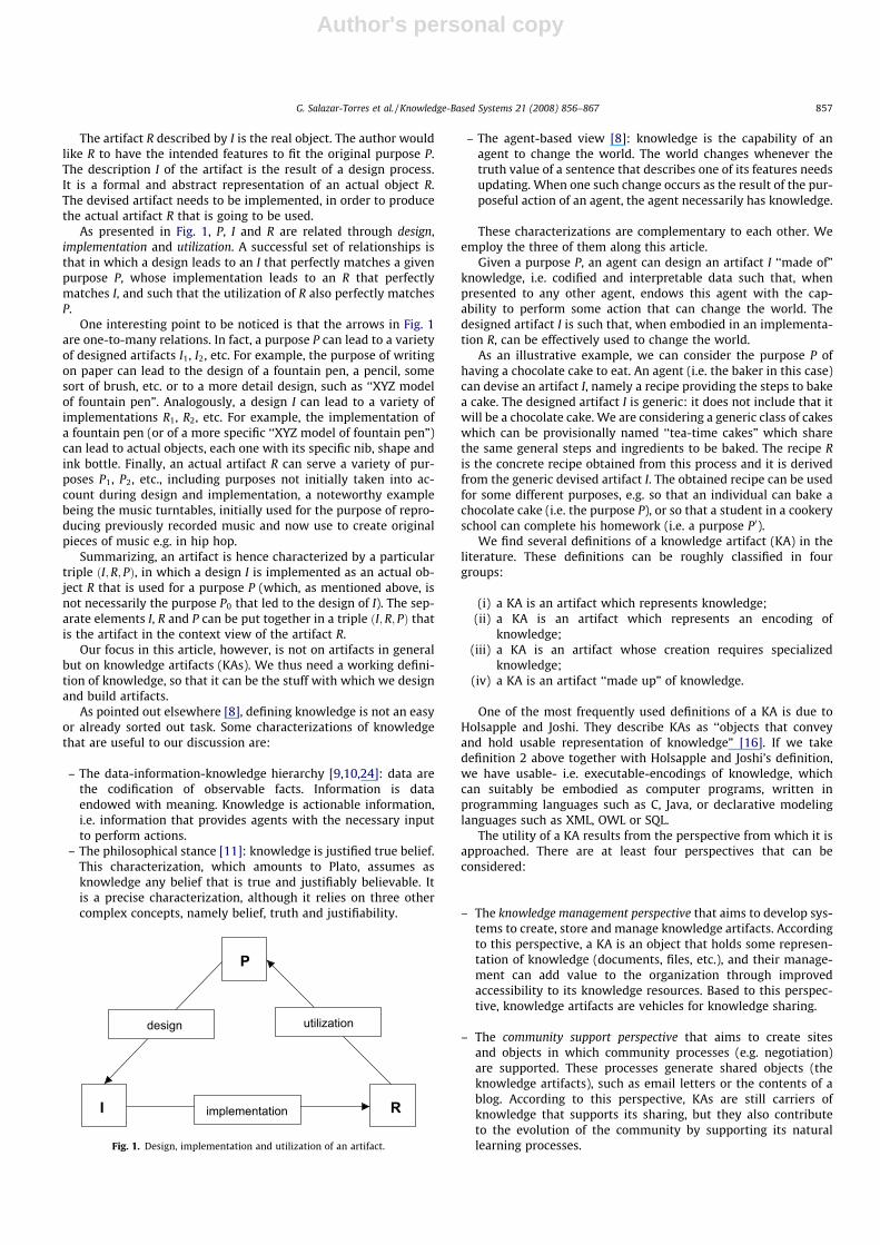
The artifact R described by I is the real object. The author wouldlike R to have the intended features to fit the original purpose P.The description I of the artifact is the result of a design process.It is a formal and abstract representation of an actual object R.The devised artifact needs to be implemented, in order to producethe actual artifact R that is going to be used.
As presented in Fig. 1, P, I and R are related through design,implementation and utilization. A successful set of relationships isthat in which a design leads to an I that perfectly matches a givenpurpose P, whose implementation leads to an R that perfectlymatches I, and such that the utilization of R also perfectly matchesP.
One interesting point to be noticed is that the arrows in Fig. 1are one-to-many relations. In fact, a purpose P can lead to a varietyof designed artifacts I1, I2, etc. For example, the purpose of writingon paper can lead to the design of a fountain pen, a pencil, somesort of brush, etc. or to a more detail design, such as ‘‘XYZ modelof fountain pen”. Analogously, a design I can lead to a variety ofimplementations R1, R2, etc. For example, the implementation ofa fountain pen (or of a more specific ‘‘XYZ model of fountain pen”)can lead to actual objects, each one with its specific nib, shape andink bottle. Finally, an actual artifact R can serve a variety of pur-poses P1, P2, etc., including purposes not initially taken into ac-count during design and implementation, a noteworthy examplebeing the music turntables, initially used for the purpose of repro-ducing previously recorded music and now use to create originalpieces of music e.g. in hip hop.
Summarizing, an artifact is hence characterized by a particulartriple ðI;R; PÞ, in which a design I is implemented as an actual ob-ject R that is used for a purpose P (which, as mentioned above, isnot necessarily the purpose P0 that led to the design of I). The sep-arate elements I, R and P can be put together in a triple ðI;R; PÞ thatis the artifact in the context view of the artifact R.
Our focus in this article, however, is not on artifacts in generalbut on knowledge artifacts (KAs). We thus need a working defini-tion of knowledge, so that it can be the stuff with which we designand build artifacts.
As pointed out elsewhere [8], defining knowledge is not an easyor already sorted out task. Some characterizations of knowledgethat are useful to our discussion are:
– The data-information-knowledge hierarchy [9,10,24]: data arethe codification of observable facts. Information is dataendowed with meaning. Knowledge is actionable information,i.e. information that provides agents with the necessary inputto perform actions.
– The philosophical stance [11]: knowledge is justified true belief.This characterization, which amounts to Plato, assumes asknowledge any belief that is true and justifiably believable. Itis a precise characterization, although it relies on three othercomplex concepts, namely belief, truth and justifiability.
– The agent-based view [8]: knowledge is the capability of anagent to change the world. The world changes whenever thetruth value of a sentence that describes one of its features needsupdating. When one such change occurs as the result of the pur-poseful action of an agent, the agent necessarily has knowledge.
These characterizations are complementary to each other. Weemploy the three of them along this article.
Given a purpose P, an agent can design an artifact I ‘‘made of”knowledge, i.e. codified and interpretable data such that, whenpresented to any other agent, endows this agent with the cap-ability to perform some action that can change the world. Thedesigned artifact I is such that, when embodied in an implementa-tion R, can be effectively used to change the world.
As an illustrative example, we can consider the purpose P ofhaving a chocolate cake to eat. An agent (i.e. the baker in this case)can devise an artifact I, namely a recipe providing the steps to bakea cake. The designed artifact I is generic: it does not include that itwill be a chocolate cake. We are considering a generic class of cakeswhich can be provisionally named ‘‘tea-time cakes” which sharethe same general steps and ingredients to be baked. The recipe Ris the concrete recipe obtained from this process and it is derivedfrom the generic devised artifact I. The obtained recipe can be usedfor some different purposes, e.g. so that an individual can bake achocolate cake (i.e. the purpose P), or so that a student in a cookeryschool can complete his homework (i.e. a purpose P0).
We find several definitions of a knowledge artifact (KA) in theliterature. These definitions can be roughly classified in fourgroups:
(i) a KA is an artifact which represents knowledge;(ii) a KA is an artifact which represents an encoding of
knowledge;(iii) a KA is an artifact whose creation requires specialized
knowledge;(iv) a KA is an artifact ‘‘made up” of knowledge.
One of the most frequently used definitions of a KA is due toHolsapple and Joshi. They describe KAs as ‘‘objects that conveyand hold usable representation of knowledge” [16]. If we takedefinition 2 above together with Holsapple and Joshi’s definition,we have usable- i.e. executable-encodings of knowledge, whichcan suitably be embodied as computer programs, written inprogramming languages such as C, Java, or declarative modelinglanguages such as XML, OWL or SQL.
The utility of a KA results from the perspective from which it isapproached. There are at least four perspectives that can beconsidered:
– The knowledge management perspective that aims to develop sys-tems to create, store and manage knowledge artifacts. Accordingto this perspective, a KA is an object that holds some represen-tation of knowledge (documents, files, etc.), and their manage-ment can add value to the organization through improvedaccessibility to its knowledge resources. Based to this perspec-tive, knowledge artifacts are vehicles for knowledge sharing.
– The community support perspective that aims to create sitesand objects in which community processes (e.g. negotiation)are supported. These processes generate shared objects (theknowledge artifacts), such as email letters or the contents of ablog. According to this perspective, KAs are still carriers ofknowledge that supports its sharing, but they also contributeto the evolution of the community by supporting its naturallearning processes.
P
I R
design utilization
implementation
Fig. 1. Design, implementation and utilization of an artifact.
G. Salazar-Torres et al. / Knowledge-Based Systems 21 (2008) 856–867 857
Author's personal copy
– The computational perspective that considers KAs as recordedrepresentations of knowledge to be used in computations withina particular problem solving method in a computational system.
– The artificial intelligence perspective that aims to separate knowl-edge from its utilization. A KA persists even without a system forits management. Moreover, its identification in an organizationcould be a useful guide for the development of knowledge-basedsystems by following a KA-based methodology.
In this paper, we are going to follow the Artificial Intelligenceperspective and consider a knowledge artifact as an artifact whoseprimary constituent is knowledge.
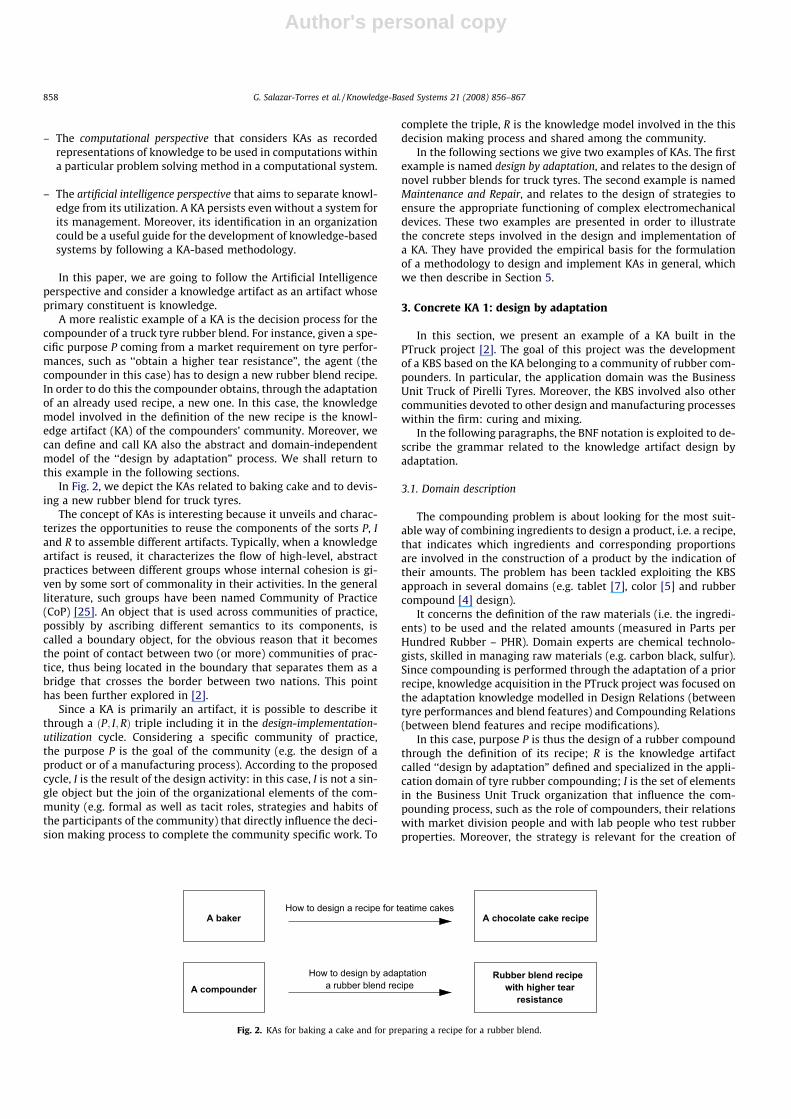
A more realistic example of a KA is the decision process for thecompounder of a truck tyre rubber blend. For instance, given a spe-cific purpose P coming from a market requirement on tyre perfor-mances, such as ‘‘obtain a higher tear resistance”, the agent (thecompounder in this case) has to design a new rubber blend recipe.In order to do this the compounder obtains, through the adaptationof an already used recipe, a new one. In this case, the knowledgemodel involved in the definition of the new recipe is the knowl-edge artifact (KA) of the compounders’ community. Moreover, wecan define and call KA also the abstract and domain-independentmodel of the ‘‘design by adaptation” process. We shall return tothis example in the following sections.
In Fig. 2, we depict the KAs related to baking cake and to devis-ing a new rubber blend for truck tyres.
The concept of KAs is interesting because it unveils and charac-terizes the opportunities to reuse the components of the sorts P, Iand R to assemble different artifacts. Typically, when a knowledgeartifact is reused, it characterizes the flow of high-level, abstractpractices between different groups whose internal cohesion is gi-ven by some sort of commonality in their activities. In the generalliterature, such groups have been named Community of Practice(CoP) [25]. An object that is used across communities of practice,possibly by ascribing different semantics to its components, iscalled a boundary object, for the obvious reason that it becomesthe point of contact between two (or more) communities of prac-tice, thus being located in the boundary that separates them as abridge that crosses the border between two nations. This pointhas been further explored in [2].
Since a KA is primarily an artifact, it is possible to describe itthrough a ðP; I;RÞ triple including it in the design-implementation-utilization cycle. Considering a specific community of practice,the purpose P is the goal of the community (e.g. the design of aproduct or of a manufacturing process). According to the proposedcycle, I is the result of the design activity: in this case, I is not a sin-gle object but the join of the organizational elements of the com-munity (e.g. formal as well as tacit roles, strategies and habits ofthe participants of the community) that directly influence the deci-sion making process to complete the community specific work. To
complete the triple, R is the knowledge model involved in the thisdecision making process and shared among the community.
In the following sections we give two examples of KAs. The firstexample is named design by adaptation, and relates to the design ofnovel rubber blends for truck tyres. The second example is namedMaintenance and Repair, and relates to the design of strategies toensure the appropriate functioning of complex electromechanicaldevices. These two examples are presented in order to illustratethe concrete steps involved in the design and implementation ofa KA. They have provided the empirical basis for the formulationof a methodology to design and implement KAs in general, whichwe then describe in Section 5.
3. Concrete KA 1: design by adaptation
In this section, we present an example of a KA built in thePTruck project [2]. The goal of this project was the developmentof a KBS based on the KA belonging to a community of rubber com-pounders. In particular, the application domain was the BusinessUnit Truck of Pirelli Tyres. Moreover, the KBS involved also othercommunities devoted to other design and manufacturing processeswithin the firm: curing and mixing.
In the following paragraphs, the BNF notation is exploited to de-scribe the grammar related to the knowledge artifact design byadaptation.
3.1. Domain description
The compounding problem is about looking for the most suit-able way of combining ingredients to design a product, i.e. a recipe,that indicates which ingredients and corresponding proportionsare involved in the construction of a product by the indication oftheir amounts. The problem has been tackled exploiting the KBSapproach in several domains (e.g. tablet [7], color [5] and rubbercompound [4] design).
It concerns the definition of the raw materials (i.e. the ingredi-ents) to be used and the related amounts (measured in Parts perHundred Rubber – PHR). Domain experts are chemical technolo-gists, skilled in managing raw materials (e.g. carbon black, sulfur).Since compounding is performed through the adaptation of a priorrecipe, knowledge acquisition in the PTruck project was focused onthe adaptation knowledge modelled in Design Relations (betweentyre performances and blend features) and Compounding Relations(between blend features and recipe modifications).
In this case, purpose P is thus the design of a rubber compoundthrough the definition of its recipe; R is the knowledge artifactcalled ‘‘design by adaptation” defined and specialized in the appli-cation domain of tyre rubber compounding; I is the set of elementsin the Business Unit Truck organization that influence the com-pounding process, such as the role of compounders, their relationswith market division people and with lab people who test rubberproperties. Moreover, the strategy is relevant for the creation of
a rubber blend recipe
A bakerHow to design a recipe for teatime cakes
How to design by adaptation Rubber blend recipewith higher tear
resistanceA compounder
A chocolate cake recipe
Fig. 2. KAs for baking a cake and for preparing a recipe for a rubber blend.
858 G. Salazar-Torres et al. / Knowledge-Based Systems 21 (2008) 856–867
Author's personal copy
R: designing recipes starting from an existing recipe and exploitingthe knowledge experienced in previously products directly guidethe community members to the definition of the ‘‘design by adap-tation” KA.
3.2. Ontological knowledge
Basic domain elements and Relations among them were identi-fied during the ontological analysis. A particular kind of relation isrepresented by Functions: specific grammar elements that describepossible recipe transformations.
Basic elements are represented by symbols describing recipenames, low and high level properties (blend features and tyreperformances).
<low level property>::="llp1" |"llp2" |. . .
<high level property>::="hlp1" |"hlp2" |. . .
<recipe>::="RECIPE_1" |"RECIPE_2" |. . .
Recipes are made up of ingredients, each one belonging to afamily (e.g. Natural Rubber-NR or Carbon Black-CB).
<ingredient>::="I1" |"I2" |"I3". . .
<family>::="F1" |"F2" |"F3" |. . .
Within a recipe it is possible to identify blends of ingredientsmade up of elements of the same family (e.g. blends of CB) and sys-tems (e.g. Polymeric Matrix, Fillers). Each system is a functionalgroup of ingredients, inserted into a recipe to provide the rubberblend with a particular feature. An example of system is the Curingone, made up of sulfur and other elements playing a fundamentalrole during tyre curing process which gives the tyre required ther-mal–mechanical properties.
<system>::="S1" |"S2" |"S3" |. . .
A family is a set of ingredients with common chemical andphysical properties. Two elements of a family are distinguishedby means of attributes (e.g. for CB, the structure and the surfacearea).
<attribute>::= <discrete attribute> | <continuousattribute> |<type><discrete attribute>::="DA1" |. . .
<discrete attribute value>::="DAV1" |"DAV2" |. . .
<continuous attribute>::="CA1" |"CA2" |"CA3" |. . .
<type>::="T1" |"T2" |. . .
<type value>::="TV1" |"TV2" |"TV3" |. . .
Considering the truck tyre domain, the product is made up ofseveral components (e.g. tread, liner). The component and the tyreutilization (i.e. axis, market segment and area) define the blendusage context (e.g. the tread for the directional truck axis used inTurkish quarries). This is important to define constraints on recipeformulation depending on its usage.
<usages>::="usage1" |"usage2" |. . .
Recipe formulations are described by sentences like ‘‘(RECIPE_1,NR01, 50)” and ‘‘(RECIPE_1, CB01, 35)”. These indicate that ingredi-ents NR01 and CB01 are in the recipe ‘‘RECIPE_1” with amounts of50 and 35 PHR, respectively.
<recipe element>::= ‘(’ <recipe> ‘,’ <ingredient> ‘,’
<amount>‘)’
<amount>::= <numeral-list> | <numeral-list>‘,’<num-eral-list><numeral-list>::= <numeral> | <numeral><numeral-list> | empty
<numeral>::= ‘0’ |‘1’ |‘2’ |‘3’ |‘4’ |‘5’ |‘6’ |‘7’
|‘8’ |‘9’
Families are sets of ingredients. Their elements are described byattributes. For instance, ‘‘CB01 belongs to CB” and ‘‘NR01 belongsto NR” express that CB01 and NR01, respectively, belong to CarbonBlacks and Natural Rubbers. Additionally, ‘‘CB is described bystructure” and ‘‘NR is described by NR Type” associate the structureattribute to CB and the NR Type attribute to NR.
<family ingredient>::= <ingredient> ‘belongs to’
<family><family attribute>::= <family> ‘is described by’
<attribute>
Each family is related to a functional system indicating whatrole specified ingredients play in the compound. Thus, sentenceslike ‘‘CB is involved in the Fillers system” and ‘‘NR is involved inthe Polymeric Matrix” state that Carbon Blacks must be includedin the Fillers system and that Natural Rubbers are in the PolymericMatrix.
<family system>::= <family> ‘is involved in’ <system>
Attribute value descriptions are given as follows.
<attribute value>::= <ingredient> ‘has value’
<amount> ‘for’ <continuous attribute>|<ingredient> ‘has value’ <type values> ‘for’
<type>|<ingredient> ‘has value’ <discrete attribute val-
ues> ‘for’ <discrete attribute>
In these examples, ‘‘CB1 has value 30 for structure”, ‘‘NR01 hasvalue RSS for NR Type” and ‘‘BR01 has value high for cis” determinethat ‘‘structure”, ‘‘NR Type” and ‘‘cis” are names of a continuousattribute (a type and a discrete attribute, respectively). Some con-straints defining recipe construction boundaries in the considereddomain can be described referring to the blend usage. These areconstraints on combination cardinality, combination amount,ingredient amounts and continuous attribute value limits.
<combination>::= <family> ‘has maximum blend cardi-
nality’ <amount> ‘for’ <usage><ingredient constraint>::=
<amount> ‘is the upper bound for’ <ingredient>‘for’ <usage>| <amount> ‘is the lower bound for’ <ingredient>
‘for’ <usage><family constraint>::= <amount> ‘is the upper bound
for’ <family> ‘for’ <usage>| <amount> ‘is the lower bound for’ <family> ‘for
’<usage><continuous attribute constraint>::=
<amount> ‘is the upper bound for’ <continuousattribute> ‘ for’ <usage>| <amount> ‘is the lower bound for’ <continuous
attribute> ‘for’ <usage>
Hence, it is possible to indicate that A is the maximum numberof elements for Carbon Black combinations for a specific usage
G. Salazar-Torres et al. / Knowledge-Based Systems 21 (2008) 856–867 859
Author's personal copy
(i.e.‘‘CB has maximum blend cardinality A for usage1”). Further-more, given L and U, the values of the lower and upper bound ofa generic interval, respectively, the amount of a particular ingredi-ent (e.g. Sulfur) could be limited for usage1 (i.e. ‘‘L is the lowerbound for Sulfur for usage1” and ‘‘U is the upper bound for Sulfurfor usage1”). Similarly, also intervals on families (e.g. CB) could bespecified for a usage (e.g. usage1) through the sentences ‘‘L is thelower bound for CB for usage1” and ‘‘U is the upper bound for CBfor usage1”. Sentences ‘‘L is the lower bound for structure forusage1” and ‘‘U is the upper bound for structure for usage1” indi-cates the interval of admissible values for the continuous attributestructure. Also system constraints not depending on the usage ex-ist: for instance ‘‘Polymeric Matrix has constant quantity” meansthat the amount augmentation of a NR ingredient is forbidden asthe associated system (i.e. the Polymeric Matrix) must have a con-stant quantity. A modification that provides substitutions not mod-ifying the total ingredient amounts is allowed.
<system constraint>::= <system> ‘has constant
quantity’
Possible recipe modifications have been identified as functions.These stand for the possible Recipe Interventions (RIs) to adapt arecipe.
<modification action>::= <shift>| <augmentation>| <substitution for family type>| <substitution for discrete attribute>| <substitution for continuous attribute>
<shift>::= ‘+’ <family> ‘�’ <family><augmentation>::= ‘+’ <family><substitution for discrete attribute>::=
<family> ‘for’ <discrete attribute> ‘
from’ <discrete attribute value> ‘to’ <discreteattribute value><substitution for continuous attribute>::= <family>‘for’ <continuous attribute><substitution for family type>::=
<family> ‘for’ <type> ‘from’ <type value> ‘to’
<type value>
For example the augmentation of Carbon Black blend amount is‘‘+CB”, while a Natural Rubber substitution taking care of their typeis specified by ‘‘NR for NR Type from RSS to SMR”, where ‘‘RSS” and‘‘SMR” are two possible NR types.
3.3. Expert knowledge
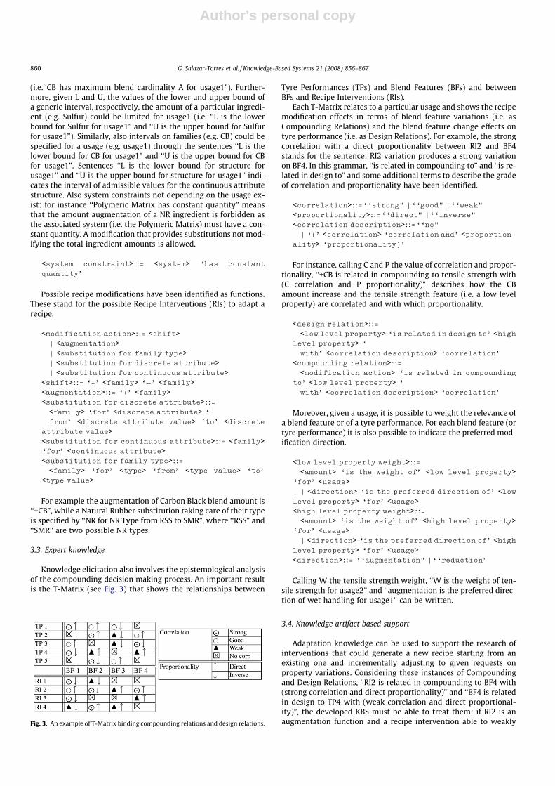
Knowledge elicitation also involves the epistemological analysisof the compounding decision making process. An important resultis the T-Matrix (see Fig. 3) that shows the relationships between
Tyre Performances (TPs) and Blend Features (BFs) and betweenBFs and Recipe Interventions (RIs).
Each T-Matrix relates to a particular usage and shows the recipemodification effects in terms of blend feature variations (i.e. asCompounding Relations) and the blend feature change effects ontyre performance (i.e. as Design Relations). For example, the strongcorrelation with a direct proportionality between RI2 and BF4stands for the sentence: RI2 variation produces a strong variationon BF4. In this grammar, ‘‘is related in compounding to” and ‘‘is re-lated in design to” and some additional terms to describe the gradeof correlation and proportionality have been identified.
<correlation>::=‘‘strong" |‘‘good" |‘‘weak"
<proportionality>::=‘‘direct" |‘‘inverse"
<correlation description>::=‘‘no"| ‘(’ <correlation> ‘correlation and’ <proportion-
ality> ‘proportionality)’
For instance, calling C and P the value of correlation and propor-tionality, ‘‘+CB is related in compounding to tensile strength with(C correlation and P proportionality)” describes how the CBamount increase and the tensile strength feature (i.e. a low levelproperty) are correlated and with which proportionality.
<design relation>::=<low level property> ‘is related in design to’ <high
level property> ‘
with’ <correlation description> ‘correlation’
<compounding relation>::=<modification action> ‘is related in compounding
to’ <low level property> ‘
with’ <correlation description> ‘correlation’
Moreover, given a usage, it is possible to weight the relevance ofa blend feature or of a tyre performance. For each blend feature (ortyre performance) it is also possible to indicate the preferred mod-ification direction.
<low level property weight>::=<amount> ‘is the weight of’ <low level property>
‘for’ <usage>| <direction> ‘is the preferred direction of’ <low
level property> ‘for’ <usage><high level property weight>::=
<amount> ‘is the weight of’ <high level property>‘for’ <usage>| <direction> ‘is the preferred direction of’ <high
level property> ‘for’ <usage><direction>::= ‘‘augmentation" |‘‘reduction"
Calling W the tensile strength weight, ‘‘W is the weight of ten-sile strength for usage2” and ‘‘augmentation is the preferred direc-tion of wet handling for usage1” can be written.
3.4. Knowledge artifact based support
Adaptation knowledge can be used to support the research ofinterventions that could generate a new recipe starting from anexisting one and incrementally adjusting to given requests onproperty variations. Considering these instances of Compoundingand Design Relations, ‘‘RI2 is related in compounding to BF4 with(strong correlation and direct proportionality)” and ‘‘BF4 is relatedin design to TP4 with (weak correlation and direct proportional-ity)”, the developed KBS must be able to treat them: if RI2 is anaugmentation function and a recipe intervention able to weaklyFig. 3. An example of T-Matrix binding compounding relations and design relations.
860 G. Salazar-Torres et al. / Knowledge-Based Systems 21 (2008) 856–867
Author's personal copy
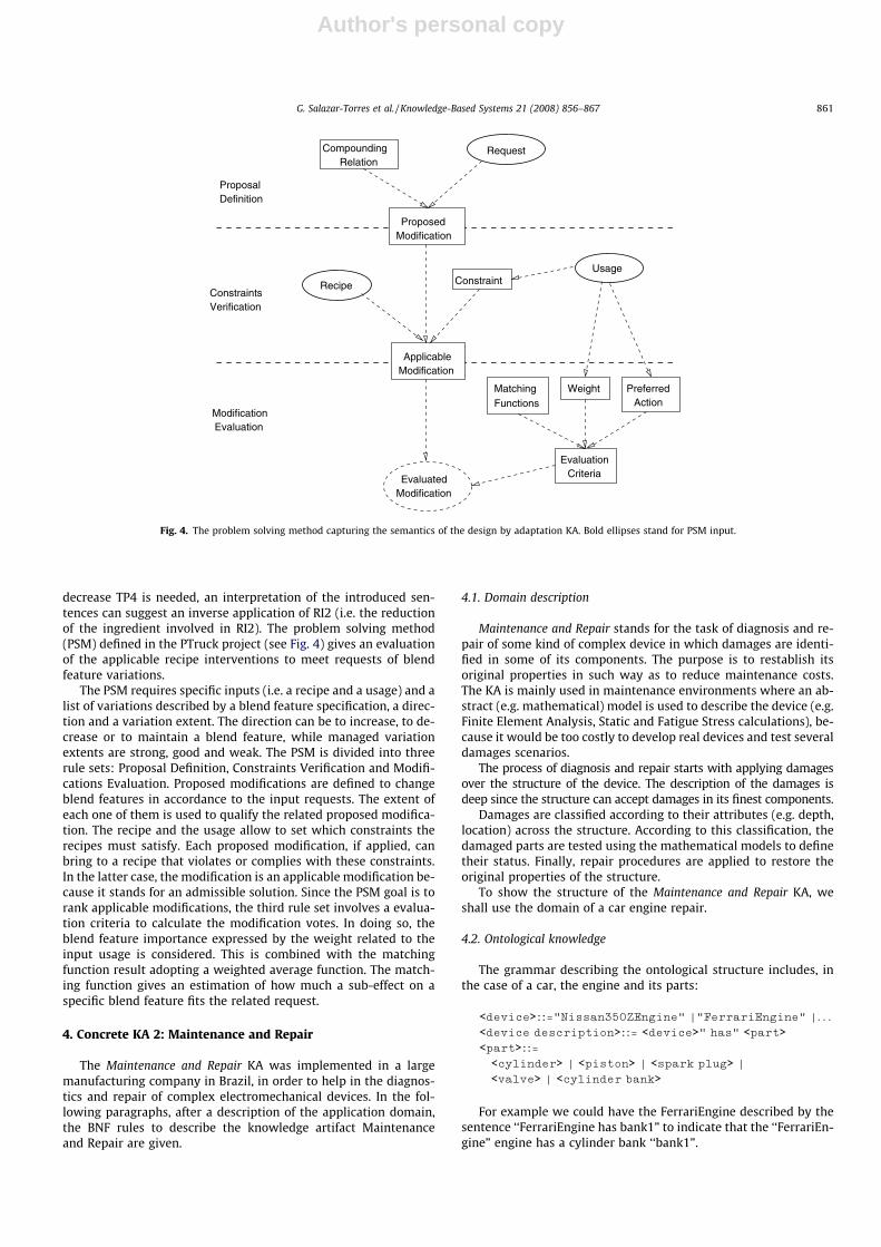
decrease TP4 is needed, an interpretation of the introduced sen-tences can suggest an inverse application of RI2 (i.e. the reductionof the ingredient involved in RI2). The problem solving method(PSM) defined in the PTruck project (see Fig. 4) gives an evaluationof the applicable recipe interventions to meet requests of blendfeature variations.
The PSM requires specific inputs (i.e. a recipe and a usage) and alist of variations described by a blend feature specification, a direc-tion and a variation extent. The direction can be to increase, to de-crease or to maintain a blend feature, while managed variationextents are strong, good and weak. The PSM is divided into threerule sets: Proposal Definition, Constraints Verification and Modifi-cations Evaluation. Proposed modifications are defined to changeblend features in accordance to the input requests. The extent ofeach one of them is used to qualify the related proposed modifica-tion. The recipe and the usage allow to set which constraints therecipes must satisfy. Each proposed modification, if applied, canbring to a recipe that violates or complies with these constraints.In the latter case, the modification is an applicable modification be-cause it stands for an admissible solution. Since the PSM goal is torank applicable modifications, the third rule set involves a evalua-tion criteria to calculate the modification votes. In doing so, theblend feature importance expressed by the weight related to theinput usage is considered. This is combined with the matchingfunction result adopting a weighted average function. The match-ing function gives an estimation of how much a sub-effect on aspecific blend feature fits the related request.
4. Concrete KA 2: Maintenance and Repair
The Maintenance and Repair KA was implemented in a largemanufacturing company in Brazil, in order to help in the diagnos-tics and repair of complex electromechanical devices. In the fol-lowing paragraphs, after a description of the application domain,the BNF rules to describe the knowledge artifact Maintenanceand Repair are given.
4.1. Domain description
Maintenance and Repair stands for the task of diagnosis and re-pair of some kind of complex device in which damages are identi-fied in some of its components. The purpose is to restablish itsoriginal properties in such way as to reduce maintenance costs.The KA is mainly used in maintenance environments where an ab-stract (e.g. mathematical) model is used to describe the device (e.g.Finite Element Analysis, Static and Fatigue Stress calculations), be-cause it would be too costly to develop real devices and test severaldamages scenarios.
The process of diagnosis and repair starts with applying damagesover the structure of the device. The description of the damages isdeep since the structure can accept damages in its finest components.
Damages are classified according to their attributes (e.g. depth,location) across the structure. According to this classification, thedamaged parts are tested using the mathematical models to definetheir status. Finally, repair procedures are applied to restore theoriginal properties of the structure.
To show the structure of the Maintenance and Repair KA, weshall use the domain of a car engine repair.
4.2. Ontological knowledge
The grammar describing the ontological structure includes, inthe case of a car, the engine and its parts:
<device>::="Nissan350ZEngine" |"FerrariEngine" |. . .
<device description>::= <device>" has" <part><part>::=
<cylinder> | <piston> | <spark plug> |
<valve> | <cylinder bank>
For example we could have the FerrariEngine described by thesentence ‘‘FerrariEngine has bank1” to indicate that the ‘‘FerrariEn-gine” engine has a cylinder bank ‘‘bank1”.
CompoundingRelation
ModificationProposed
Request
Recipe
ModificationApplicable
ConstraintUsage
MatchingFunctions
Weight PreferredAction
EvaluationCriteria
ModificationEvaluated
ProposalDefinition
ConstraintsVerification
ModificationEvaluation
Fig. 4. The problem solving method capturing the semantics of the design by adaptation KA. Bold ellipses stand for PSM input.
G. Salazar-Torres et al. / Knowledge-Based Systems 21 (2008) 856–867 861
Author's personal copy
Since the purpose of the Maintenance and Repair KA is to repairfine parts, it is necessary to go deeper in the description of the de-vice (e.g. cylinders):
<cylinder arrange>::="v" |"flat" |"inline"
<cylinder bank>::="bank1" |"bank2"
<cylinder bank description>::=<cylinder bank>" has" <cylinder arrange>" arrange" |
<cylinder bank>" has" <number>"cylinders" |
<cylinder bank>" is composed by" <cylinder> |
<cylinder material>::="aluminum" |. . .
<cylinder>::="cylinder1" |"cylinder2" |. . .
<cylinder description>::=<cylinder>" contains" <piston> |
<cylinder>"has depth" <real number>|<cylinder>" has" <cylinder material>
Following the previous example, we could describe the cylinderbank ‘‘bank1” with the sentences ‘‘bank1 has v arrange”, ‘‘bank1has 10 cylinders”, ‘‘bank1 is composed by cylinder1” and ‘‘cylin-der1 contains piston1”. Further description could include the pis-ton, its material (e.g. aluminum) or thickness and finer elementslike the piston head and skirt:
<piston>::="piston1" |"piston2" |. . .
<piston descripton>::=<piston>" has" <piston material>" material" |
"(" <piston>"," <piston component>")"<system>::="mm" |"cm"
<piston component>::="piston1head"|"piston1skirt" |. . .
<piston material>::="aluminum" |"ceramic–aluminum"
<piston component type>::="piston head" |"piston
skirt"
<piston component description>::="(" <piston component>"," <piston component type>,<piston component property>"," <amount>
<system>")"<piston component property>::="thickness"<damageable component>::= <piston component>
<damageable component type>::= <piston component
type><damageable component property>::= <piston compo-
nent property>
We could describe ‘‘piston1” head by ‘‘(piston1, piston1head)”to state that ‘‘piston” is composed of ‘‘piston1head”. In the sen-tence ‘‘(piston1head, piston head, thickness, 5 mm)” we describedeeply ‘‘piston1head” saying that it is piston head part type andhas a thickness of 5 mm.
4.3. Epistemological knowledge
Now we have to describe what kinds of damage can be appliedto this device and how they are related to the elements of the carengine. It is worth remarking that that not all of the parts canhave a related damage. The basic idea is to have damages catego-rized by status and class. Status tells us how to apply a repair (ifit can be repaired) and the class tells us what kind of damage it is.This last property can also indicate if a particular damaged partcan have a provisioned or permanent repair. The purpose of thisKA is to reset the initial properties of the damaged parts, so thatthe entire device can continue working:
<repair>::="repair1" |"repair2" |. . .
<repair type>::="temporal" |"permanent" |. . .
<repair description>::="(" <repair>"," <repair type>"," <damage>")"
<damage>::="damage1" |"damage2" |. . .
<damage type>::= <mechanical> | <termo-mechanical><mechanical>::="crack" |"hole" |. . .
<damage status>::="admissible" |"permanent" |. . .
<damage description>::=<damage>" is a" <damage type> |
"(" <damage>"," <damageable component>","<damageable component property>"," <amount>
<system>")"<damage classified>::="("<damage>","<damagestatus>")"<damage limit>::=
DefinitionsDamage
Damage StatusClassification
LimitDamage
ClassifiedDamage
ApplicationRepair
PartRepaired
NumericalProcess
Repair
DescriptionDevice
DamageDamaged
Part
User Input
Inference Step
Rule Input
User Input User Input
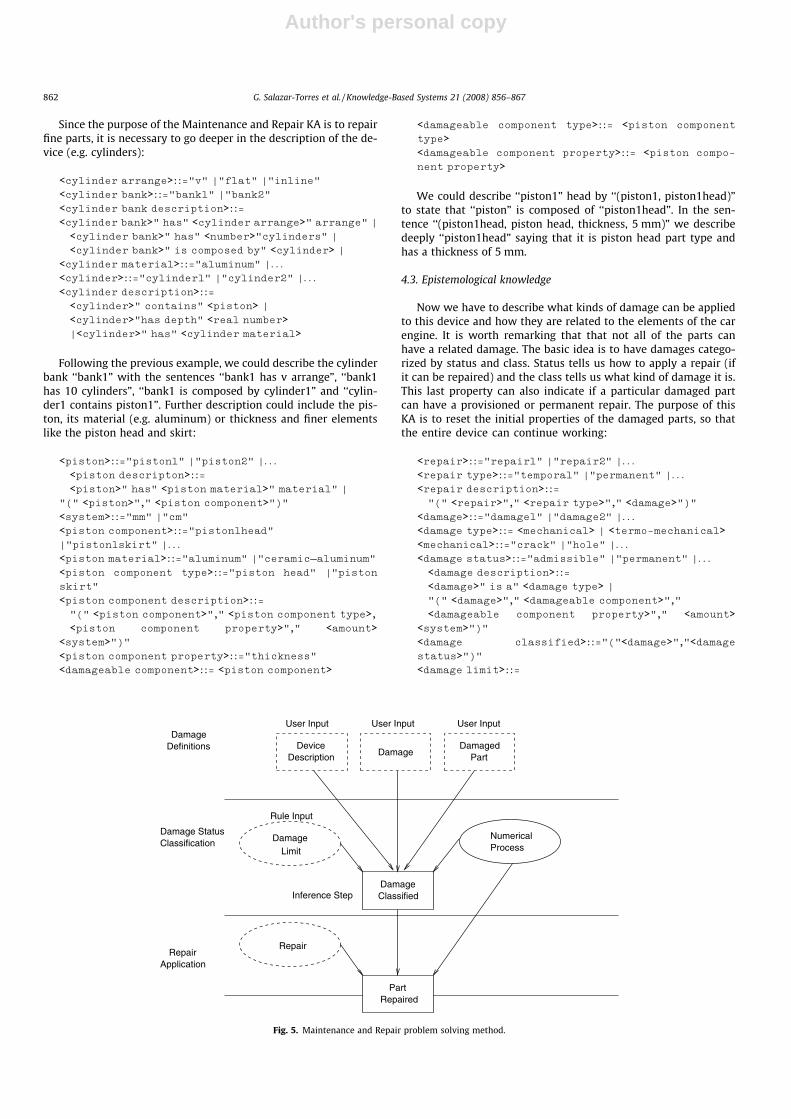
Fig. 5. Maintenance and Repair problem solving method.
862 G. Salazar-Torres et al. / Knowledge-Based Systems 21 (2008) 856–867
Author's personal copy
"(" <damage status>"," <damageable component
type>","<damageable component property>"," <amount>"
Let’s assume that ‘‘piston1” has a damage in its head ‘‘(dam-age1, piston1head, thickness, 1.5 mm)”. Every damage reducessome property of the part in this case, its thickness (e.g. in aspark plug it could reduce its heat resistance). We could refineour description with the sentence ‘‘damage1 is a crack”, meaningthat thickness reduction on the piston has been caused by acrack.
4.4. Knowledge artifact based support
The PSM showed in Fig. 5 determines the status of the damage(e.g. admissible status means that a damage is allowed to stay inthe part) and apply a repair procedure to restore initial propertiesof that part.
Following our example, we have to determine the status of‘‘damage1”. For this purpose we use the ‘‘hdamage limiti” grammarrule to establish the maximum amount of reduction on a part prop-erty. If the damage amount is greater than that maximum, then it isclassified as a repair, otherwise it is an admissible or another kindof damage status.
In our example we could have a limit rule of 20% of the ori-ginal piston head’s thickness for admissible damages ‘‘(admissi-ble, piston head, thickness, 20%)”, thus ‘‘damage1” is not anadmissible repair and need a permanent repair indicated bythe rule ‘‘(damage1, permanent)”. Before applying the repair,the damaged part is submitted to the mathematical proceduresto establish if the manufacturer has indeed a repair procedurefor this kind of repair. After this process we could have a ruledescribing the repair ‘‘(repair1,permanent,damage1)”. Generally,in the case of damaged piston heads, the entire piston isreplaced.
5. Development of KA-based systems
In this section we propose an Agile knowledge engineeringmethod based on XP.K to develop KA-based systems (KABS). Foran author A to build an artifact R made of knowledge (Fig. 1), theremust be a ‘‘method” to elicit the corresponding relevantknowledge.
The intent of the method here discussed is to get computa-tional the knowledge artifact detected. The KA-based System isthus a knowledge artifact embodied in the form of softwaresystems.
Many methods (and methodologies) in the field of KnowledgeEngineering have been proposed to elicitate knowledge, amongwhich CommonKADS and MIKE are the most used in the industry.Despite their success, these methods do not effectively handle thecharacteristics of knowledge modeling (an iterative, collaborativeand evolutionary task [17,20,21]) because they are based on awaterfall model.
In [17] and more recently in [1], two new knowledgeengineering methods based on the Agile Manifesto were pro-posed: XP.K and RapidOWL. These methods claim to be moresuitable for the knowledge modeling task since the AgileManifesto principles match the characteristics of knowledgemodeling.
The values, principles and practices of the proposed method arepresented in the next sections. This proposal is based on our previ-ous experience implementing the PTruck project and more re-cently at the project in Brazil.
5.1. Values
5.1.1. CommunityKnowledge Engineers and KA-based Systems (KABS) developers
need to see themselves like members of the community of practicethat develops a KABS, and furthermore to get aware of the exis-tence of the user’s CoP.
In the first case, as suggested by the Communication XP value,maintaining a fluent communication is necessary because it as-sures CoP’s practice. It’s worth to notice the KA’s role as a relevantmean of communication among team members.
In the second case, the CoP users see the organization as a set ofCommunities of Practice (CoPs) to have a better notion of who arethe people involved in the KABS development.
The principle of peripheral participation is about the kind ofinteraction that exist between the CoP of Knowledge Engineersand Developers and the CoP of users. The practice of Joint KA Designdetails the activities in this interaction.
It’s important to consider the XP values of Humility and Respectbecause it brings to the Knowledge Engineers and Developers abehavioural code with CoP members, which frequently do not havetraining in knowledge modeling or programming.
5.1.2. SimplicitySimplicity is a consequence of using a KA in the development of
a KABS. In fact, since the KA is a cognitive pattern owned by theCoP itself, the use of the grammar directly derived from the KAmakes the integration among CoP members simpler.
An important recommendation coming from XP.K suggests todesign knowledge models as simple as possible. We are consider-ing this hint in our method because though the interaction is gotsimple by the use of the KA, the design phase (as defined by Wino-grad in [26]) is difficult and complex. The design is even more com-plex because the development of the KABS requires all the threedimensions of the knowledge model (intensional, extensional andreasoning, see [3]).
5.1.3. FeedbackA tool that gives support to the KA design is the main source to
obtain feedback by the people involved in the development of aKABS. This tool should allow to configure tests on all the dimen-sions of the KA-based model, along with a simple and intuitiveGUI that will provide information about the KA status.
Besides that, this tool must generate source code in a suitableprogramming language (e.g. Java, C#) reflecting the architectureof a KABS ready to be integrated with the GUI.
5.1.4. CourageCourage is needed to abandon a KA design when this does not
fulfill the requirements of the CoP where the KA is beingdeveloped.
It is worth to notice that although much of the source code hasto be abandoned, the results of the ontological and epistemologicalanalysis remain intact, since they can be stored independently ofthe KA instance and capable to be reused in another KA.
5.2. Principles
Many principles of XP.K are reused here, though, some of themaffect more the development of a KA and are further analysed.Fig. 6 shows the values and principles of our method.
5.2.1. Work with people’s instinctsWe are basing our method on CoP theory, so the tacit knowl-
edge of the CoP members is important to design a KA.
G. Salazar-Torres et al. / Knowledge-Based Systems 21 (2008) 856–867 863
Author's personal copy
5.2.2. Rapid feedback and concrete experimentsAs a result of using a tool like the one suggested in the descrip-
tion of the Feedback value, the experiments with source code willbe faster since the tool can generate it based on the KA architec-tural framework [3] and the KA-based model.
This tool should also perform automated tests and logical con-sistency verification on the KA-based model to prevent late costlymodifications.
5.2.3. Embracing changeIt is possible that much of the generated source code be aban-
doned to start the design of a new KA. This principle gives supportto the value of Courage.
5.2.4. Peripheral participationThe method we are proposing considers two main communities
of practice. People belonging to the first one are Users and Experts,while people belonging to the second one are Knowledge Engineersand Developers.
The interaction among members of both communities begins atthe peripheral. In the first scenario, the CoP of Users and Expertsaccept a Knowledge Engineer or Developer as a new user of thecommunity. He can get to the core of the CoP where knowledgeis hold by the Experts. This activity helps the engineers and devel-opers to have a better notion of the development scope of theKABS.
The practices of on-site domain expert and Joint KA Design showthe second scenario, when the Expert participates in the CoP ofKnowledge Engineers and Developers. In this case, the interactionis also peripheral since the Experts gradually learn about program-ming or knowledge modeling techniques at the same time theKA-based model is created.
5.2.5. Traveling lightOur methodology promotes the manipulation of a KA through a
design tool with a appropriate GUI. This GUI presents the KA-basedmodel dimensions in an effective way. The KA is the main object tobe manipulated during the KABS development process. Other arti-facts can be used to support the development of the KABS like UMLdiagrams or electronic worksheets as long as the KA is kept as themain model.
5.3. Practices
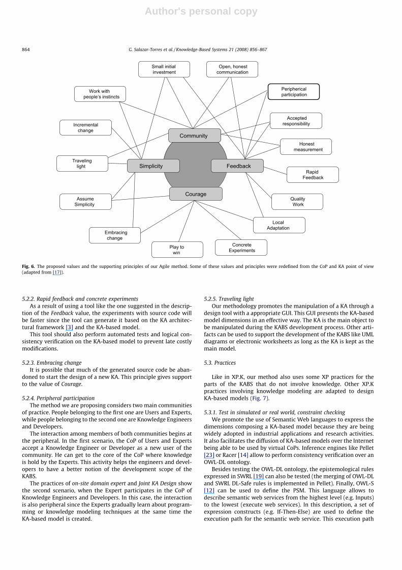
Like in XP.K, our method also uses some XP practices for theparts of the KABS that do not involve knowledge. Other XP.Kpractices involving knowledge modeling are adapted to designKA-based models (Fig. 7).
5.3.1. Test in simulated or real world, constraint checkingWe promote the use of Semantic Web languages to express the
dimensions composing a KA-based model because they are beingwidely adopted in industrial applications and research activities.It also facilitates the diffusion of KA-based models over the Internetbeing able to be used by virtual CoPs. Inference engines like Pellet[23] or Racer [14] allow to perform consistency verification over anOWL-DL ontology.
Besides testing the OWL-DL ontology, the epistemological rulesexpressed in SWRL [19] can also be tested (the merging of OWL-DLand SWRL DL-Safe rules is implemented in Pellet). Finally, OWL-S[12] can be used to define the PSM. This language allows todescribe semantic web services from the highest level (e.g. Inputs)to the lowest (execute web services). In this description, a set ofexpression constructs (e.g. If-Then-Else) are used to define theexecution path for the semantic web service. This execution path
Community
FeedbackSimplicity
Courage
investmentSmall initial
AssumeSimplicity
Travelinglight
changeIncremental
Embracingchange
Play towin
ConcreteExperiments
AdaptationLocal
FeedbackRapid
measurementHonest
Acceptedresponsibility
Open, honestcommunication
Periphericalparticipationpeople’s instincts
Work with
QualityWork
Fig. 6. The proposed values and the supporting principles of our Agile method. Some of these values and principles were redefined from the CoP and KA point of view(adapted from [17]).
864 G. Salazar-Torres et al. / Knowledge-Based Systems 21 (2008) 856–867
Author's personal copy
can be reused to define the sequence of steps in a PSM. Moreover,OWL-S engines ([22,13]) can execute these descriptions.
5.3.2. Shared symbol groundingThe KA serves as a metaphor for the development team. The
metaphor is drived by the message the KA brings (e.g. in the caseof design by adaptation, this message is partially given by thegrammar elements ‘‘hlow level propertyi”, ‘‘hhigh level propertyi”,‘‘hrecipei”).
5.3.3. Simple knowledge modelA KA-based model includes different kind of knowledge models
(e.g. ontological) which must be modeled keeping in mind the cur-rent needs. The practice of Rapid Feedback provides informationabout the consistency of these models to help guiding modeling.
5.3.4. Joint KA designIn XP.K, the practice of Joint Ontology Design was defined so the
Knowledge Engineer and the Domain Expert were able to find asuitable representation for the domain ontology. In our case, thisis translated to designing a KA.
The goal is to build a KA-based model composed by a grammar,its sentences and the PSM, formally expressing the ontological andepistemological CoP knowledge along with a method to processthis elements.
The grammar is designed after and ontological and epistemo-logical analysis of the application domain. It is derived from adomain-dependant non-formal vocabulary (e.g. the professionallanguage) used by the Domain Experts. In other words, theKA-based model is a knowledge model specified by sentencesusing the designed language.
Entities, properties, relationships, processes are defined by thegrammar of the language composing the intensional domainmodel.
In order to avoid the ambiguity of the model due to the use ofthe CoP’s natural language, it is mandatory this language to beformal. The Knowledge Engineer promotes the participation of theExperts in both tasks: the activities defining the language (e.g.
grammar and semantics) and the specification of the initial KAbased model to be implemented in the KABS and maintained bythe Expert Maintainer.
5.3.5. Modeling standardThis is defined by both Knowledge Engineers and the Experts.
Depends greatly on the professional language used by the COP’smembers and has an impact on the definition of the KA-basedmodel.
5.3.6. Refactoring KA dimensionsIn XP.K the practice of Refactoring and Round-Trip Engineering is
defined. It involved techniques to generate source code from UMLmodels and viceversa.
This cannot be done in our case since we are using OWL-DL asmetamodel language. However, refactoring in the context of KABScan be performed in each dimension of the KA-based model and beof two types: (1) External: every dimension is an independentOWL-DL entity (e.g. ontology), it can be reused in the design ofanother KA, (2) Internal: Knowledge Patterns [6] can be useful toapply recurrent patterns in ontology modeling.
Practices in KA–based systems development
XP.K Practices Additional Practices
Round–Trip. Eng.,Refactoring
Constraint Checkingreal world¸
Testing in simulated or
40 hour Week
Planning
On–Site Expert
Simple knowledge model
Shared Symbol Grounding
Modeling Standard
Joint ontology design Joint CKA Design
CKA dimensions refactoring
Fig. 7. The practices that compose our method are inspired by XP.K practices. Some of them were replaced like the case of Joint KA Design (adapted from [17]).
P
I
I R
PR
Maintenance and Repair
Car Repairing
Fig. 8. The Maintenance and Repair KA reified in the car repairing domain.
G. Salazar-Torres et al. / Knowledge-Based Systems 21 (2008) 856–867 865
Author's personal copy
6. Discussion and future work
In this article, we have described two concrete KAs related totwo different projects. Both its Design by Adaptation and theMaintenance and Repair KAs have guided us in the developmentof specific software systems, and these experiences have alsoformed the basis of our proposal of a general method to implementKA-based systems.
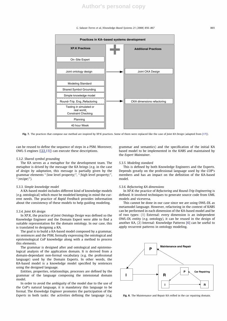
The theory of knowledge artifacts given in the first sections ofthis article can be further enriched. For instance, the relationshipbetween concrete KAs and abstract KAs (such as the ‘‘Maintenanceand Repair” KA) must still be further analyzed and explained: Theabstract KA ‘‘Maintenance and Repair” has as its purpose P to diag-nose and repair some kind of complex device. Its implementation Rcan be represented by the ontological elements present in thegrammar and by the problem solving method describing how thesentences written in this grammar have to be considered. In thedomain of car repair, this KA is reified with specific knowledge(e.g. car repair) to fulfill the purpose of fixing a car model. This re-sults in a concrete KA with a different purpose P (fix damages in acar engine) and an implementation I (the software system or KA-based System). In Fig. 8 this relationship is shown.
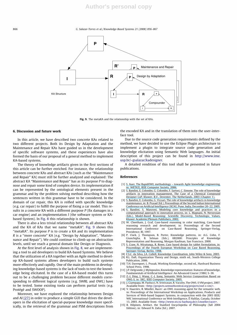
There is also a less trivial relationship between all abstract KAsand the KA of KAs that we name ‘‘metaKA”. Fig. 9 shows this‘‘metaKA”. Its purpose P is to create a KA and its implementationR is a ‘‘more concrete” KA (e.g. ‘‘Design by Adaptation”, ‘‘Mainte-nance and Repair”). We could continue to climb up on abstractionlevels, until we reach a general domain like Design or Diagnosis.
At the first level of analysis shown in Fig. 8, we are implement-ing a tool to aid developers to build KA-based Systems. We believethat the utilization of a KA together with an Agile method to devel-op KA-based systems allows developers to build such systemsmore effectively and rapidly. One of the main problems in develop-ing knowledge-based systems is the lack of tools to test the knowl-edge being elicitated. In the case of a KA-based model this turnsout to be a challenging problem because different models corre-sponding to different logical systems (e.g. SWRL and OWL) haveto be tested. Some existing toola can perform partial tests (e.g.Protégé and SWOOP).
Moreover, we have explored the relationship between Designand AI [27] in order to produce a simple GUI that drives the devel-opers in the elicitation of special-purpose knowledge more specif-ically, in the retrieval of the grammar and PSM descriptions from
the encoded KA and in the translation of them into the user-inter-face tool.
Due to the source code generation requirements defined by themethod, we have decided to use the Eclipse Plugin architecture toimplement a plugin to integrate source code generation andknowledge elicitation using Semantic Web languages. An initialdescription of this project can be found in http://www.ime.usp.br/~gsalazar/kadesigner.
A detailed rendition of this tool shall be presented in futurepublications.
References
[1] S. Auer, The RapidOWL methodology – towards Agile knowledge engineering,in: WETICE, IEEE Computer Society, 2006.
[2] S. Bandini, E. Colombo, G. Colombo, F. Sartori, C. Simone, The role of knowledgeartifacts in innovation management, The Case of a Chemical CompoundDesigner CoP, Kluwer, B.V., Deventer, The Netherlands, 2003 (Chapter 1).
[3] S. Bandini, E. Colombo, G. Vizzari, The role of knowledge artifacts in knowledgemaintenance, in: B. Prasad (Ed.), Proceedings of the Second Indian InternationalConference on Artificial Intelligence (IICAI), Pune, India, December 20–22, 2005.
[4] S. Bandini, S. Manzoni, Modeling core knowledge and practices in acomputational approach to innovation process, in: L. Magnani, N. Nersessian(Eds.), Model-Based Reasoning: Scientific Discovery, Technologic, Values,Kluwer Academic/Plenum Publishers, 2002.
[5] W. Cheetham, J. Graf, Case-based reasoning in color matching, Case-basedreasoning research and development, in: Proceedings of the SecondInternational Conference on Case-Based Reasoning, Springer-Verlag,Providence, RI, 1997.
[6] P. Clark, J. Thompson, B. Porter, Knowledge patterns, in: A.G. Cohn, F.Giunchiglia, B. Selman (Eds.), KR2000: Principles of KnowledgeRepresentation and Reasoning, Morgan Kaufman, San Francisco, 2000.
[7] S. Craw, N. Wiratunga, R. Rowe, Case based design for tablet formulation, in:Proceedings of the Fourth European Workshop on Case Based Reasoning,Springer-Verlag, Berlin, 1998.
[8] F.S.C. da Silva, J.A. Cullell, Knowledge Coordination, John Wiley & Sons, 2003.[9] R.L. Daft, Organization Theory and Design, ninth ed., South-Western College
Publication, 2006.[10] T.H. Davenport, L. Prusak, Working Knowledge, second ed., Hardvard Business
School Press, 1998.[11] J.P. Delgrande, J. Mylopoulos, Knowledge representation: features of knowledge,
Fundamentals of Artificial Intelligence: An Advanced Course (1986) 3–38.[12] Z.-J. Ding, J. Wang, C.-J. Jiang, Semantic Web Service Composition Based on
OWL-S, in: SKG, IEEE Computer Society, 2005.[13] J. Giampapa, M. Paolucci, N. Srinivasan, R. Vaculin, The OWL-S VM project, 2007.
Available from: <http://projects.semwebcentral.org/projects/owl-s-vm/>.[14] V. Haarslev, R. Möoller, Racer: an OWL reasoning agent for the semantic web,
in: Proceedings of the International Workshop on Applications, Products andServices of Web-based Support Systems, in conjunction with the 2003 IEEE/WIC International Conference on Web Intelligence, Ê Halifax, Canada, October13, 2003. Available from: <http://www.sts.tu-harburg.de/r.f.moeller/racer>.
[15] R. Hilpinen, Artifact, the Stanford Encyclopedia of Philosophy (fall 2004Edition), in: Edward N. Zalta (Ed.), 2007.
P Maintenance and Repair
I R P
I R
Car RepairI P
I R
Compounder
R
P Design by Adaptation
P
I R
R’
KA Structure
Fig. 9. The metaKA and the relationship with the set of KAs.
866 G. Salazar-Torres et al. / Knowledge-Based Systems 21 (2008) 856–867

Author's personal copy
[16] C.W. Holsapple, K.D. Joshi, Organizational knowledge resources, DecisionSupport Systems 31 (1) (2001) 39–54.
[17] H. Knublauch, An Agile Development Methodology for Knowledge-BasedSystems Including a Java Framework for Knowledge Modeling and AppropriateTool Support, Ph.D. thesis, Fakultät für Informatik, Universität Ulm, 2002.
[18] G.D. Michelis, Aperto, moteplice, continuo, Dunod, Milano, 1998.[19] M.J. O’Connor, H. Knublauch, S.W. Tu, B.N. Grosof, M. Dean, W.E. Grosso, M.A.
Musen, Supporting rule system interoperability on the semantic web withSWRL, in: Y. Gil, E. Motta, V.R. Benjamins, M.A. Musen (Eds.), Proceedings of theFourth International Semantic Web Conference, ISWC 2005, in: Lecture Notes inComputer Science, vol. 3729, Springer, Galway, Ireland, November 6–10, 2005.
[20] W. Rammert, M. Schlese, G. Wagner, J. Wehner, R. Weingarten,Wissensmaschinen: Soziale Konstruktion eines technischen Mediums DasBeispiel Expertensysteme, Campus Verlag, Frankfurt, Germany, 1998.
[21] G. Salomon, Distributed cognitions: Psychological and EducationalConsiderations., Cambridge University Press, Cambridge, UK, 1993.
[22] E. Sirin, J.A. Hendler, B. Parsia, Interactive composition of semantic webservices, in: WWW (Posters), 2003.
[23] E. Sirin, B. Parsia, B.C. Grau, A. Kalyanpur, Y. Katz, Pellet: a practical OWL-DLreasoner, Journal of Web Semantics 5–2 (2007).
[24] A. Tiwana, The Knowledge Management Toolkit: Practical Techniques forBuilding a Knowledge Management System, Prentice Hall, 1999.
[25] E. Wenger, Communities of Practice: Learning, Meaning and Identity,Cambridge University Press, Cambridge, 1998.
[26] T. Winograd, Bringing Design to Software, Addison-Wesley, 1996.[27] T. Winograd, Shifting viewpoints: artificial intelligence and human–
computer interaction, Artificial Intelligence 170 (2006) 1256–1258.
G. Salazar-Torres et al. / Knowledge-Based Systems 21 (2008) 856–867 867