Embed Size (px)
Citation preview


.'
I •
r
The Conservation of Artifacts Made from Plant Materials


The Conservation of Artifacts Made from Plant Materials Mary-Lou E. Florian Dale Paul Kronkright Ruth E. Norton

Cover: Warao basketry tray, Venezuela
Fowler Museum of Cultural History, UCLA, X6S-776S.
Course Coordinator: Benita Johnson Publications Coordinator: Irina Averkieff, GCI Design: Jacki Gallagher, GCI Technical Illustration: Janet Spehar Enriquez and Laurie Grove Printing: Princeton University Press
©1990 The J .Paul Getty Trust All rights reserved
Library of Congress Cataloging-in-Publication Data
Florian, Mary-Lou E . The conservation of artifacts made from plant materials / Mary-Lou
E. Florian, Dale Paul Kronkright, Ruth E. Norton Includes bibliographical references and index. ISBN 0-89236-160-3 1 . Plant remains (Archaeology)--Collection and preservation.
I. Kronkright, Dale Paul. II. Norton, Ruth E. III. Title. CC79.5 .P5F58 1990 930 . 1 ' 028 ' 5 --dc20

THE GETTY CONSERVATION INSTITUTE
The Getty Conservation Institute ( GCI), an operating program of the J. Paul Getty Trust, was created in 1982 to enhance the quality of conservation practice in the world today. Based on the belief that the best approach to conservation is interdisciplinary, the Institute brings together the knowledge of conservators, scientists, and art historians. Through a combination of in-house activities and collaborative ventures with other organizations, the Institute plays a catalytic role that contributes to the conservation of our cultural heritage. The Institute aims to further scientific research, to increase conservation training opportunities, and to strengthen communication among specialists.


Chapter 1 Mary-Lou E. Florian
Chapter 2 Mary-Lou E. Florian
Contents
Preface . . . . . . . . . . . . . . . . . . . . . . . . . . . . . . . . . . . . . . Xl
Plant Anatomy: An Illustrated Aid to Identification
The Classification and Nomenclature of Plants Morphology and Development
Plant Morphology . . . Embryonic Development
Primary Tissues . . . . . . . . Arrangement of Primary Tissues in Plant Parts Basic Cell Types of Primary Tissue . . . . . .
Secondary Tissues Organization of Secondary Tissues in a Woody Stem Secondary Xylem . Secondary Phloem . . . . . . . . Periderm . . . . . . . . . . . . .
Chemistry and Stmcture of the Cell Wall References
Identification of Plant and Animal Materials in Artifacts
Sampling . . . . . . . . . . . . . . . . . . . . . . . . . . . . . . Preparation and Staining of Microscope Slides of Basketry Materials
Materials, Supplies, and Equipment Cutting Sections of the Sample . . . . . . . . Orientation of Sections . . . . . . . . . . . . Wet-Mollnt Preparation of Microscope Slides Slide Preparation of Archaeological Artifact Material Methods of Observation . . . . . . . . . . Staining Samples . . . . . . . . . . . . . . Preparation, Labeling, and Storage of Slides Standards of Documented Materials
1
1 2 2 3 3 5 7
13 14 15 18 19 20 27
29
30 31 32 33 33 34 34 35 35 37 37
Chapter 3 Ruth E. Norton
Chapter 4 Dale Paul Kronkright
Identification of Plant and Animal Fibers Plant Hairs . . . . . . . . . . Plant Leaf and Stem Fibers Protein Fibers of Animal Origin
Identification of Plant Parts and Tissue Stems, Rootlets, and Rhizomes Monocot Leaves Secondary Phloem Tissue True Bark Tissue Wood Tissue Wood Origin (Branch, Root, or Trunk)
Cited References . . Additional Reading
Technology of Plant Materials Used in Artifacts
General Processing Procedures Cultivation and Harvesting Drying . . . . . . . Retting and Cooking Fiber Extraction . . . Wetting and Heating Bleaching . . . . . . Dyeing
General Construction Techniques Removal of Material Reshaping . . . . . . . . . Joining Interworking of Fibers and Elements Decoration and Finishes . . . . . . .
Cultural Modification of Artifacts Plant Materials Used in Artifact Construction
Stems, Trunks, and Roots Leaves . . . . . Seeds and Fruit
Conclusion References . . . . . .
Deterioration of Artifacts Made From Plant Materials
Factors in Deterioration . . . . . . . . .
Conservation as Deterioration . . . Focusing the Study of Deterioration Properties and Levels of Organization Problematic Conditions . . . . . . . Deterioration and Ethnographic Evidence
. 38
. 39
. 44
. 52
. 57
. 57
. 63
. 66
. 71
. 72
. 75
. 78
. 79
83
. 84
. 84
. 85
. 85
. 86
. 86
. 86
. 87
. 87
. 87
. 88
. 89
. 89
. 97
. 98
. 99
. 99 1 12 125 1 33 1 3 3
139
140 140 1 42 143 144 144

ChapterS Ruth E. Norton
The Processes of Deterioration Physical Deterioration Chemical Deterioration Mechanical Deterioration Biological Deterioration Documenting Evidence of Deterioration: Tests and Analyses
References
Conservation of Artifacts Made from Plant Materials
Collection Care . . . . . . .
Ethical Considerations Labeling Artifacts Conservation Surveys Storage and Display Pest Management Transportation and Shipment Field Conservation . . . . . .
Conservation Treatment Procedures Documentation Cleaning . . . Reshaping Deacidification Consolidation and Restoration of Flexibility Mending . Restoration
Conclusion References
Appendices
1 Mending Structures with Twisted and Folded Mulberry Paper Strands Dale Paul Kronkright
2 Construction of Storage Boxes and Folders Ruth E. Norton
3 Characteristics of Adhesives Ruth E. Norton
4 Dyeing Cellulosic Materials With Fiber-Reactive Dyes Ruth E. Norton
. 145
. 146
. 165
. 175
. 178
. 1 82
. 1 87
195
. 196
. 196
. 197
. 200
. 200
. 205
. 205
. 208
. 208
. 2 10
. 2 15
. 229
. 233
. 235
. 241
. 264
. 269
. 270
287
. 287
. 293
. 299
. 301
Glossary . . . . . . . . . . . . . . . . . . . . . . . . . . . . . . . . . . . . 309
Index . . . . . . . . . . . . . . . . . . . . . . . . . . . . . . . . . . . . . . 315


Preface
O bjects made from plant materials comprise a large portion of the ethnographic
material in collections around the world. Conservation of such perishable arti
facts is especially problematic when they are housed in climates different from those
in which they were collected, as is often the case.
A certain amount of research into the conservation of plant material arti
facts has been carried out and published. However, to date no substantive volume
exists that brings together this scattered information from various disciplines.
The present publication, while far from exhaustive in its treatment of the subject,
attempts to fill this lacuna.
In July of 1987, the Getty Conservation Institute sponsored and hosted in
Los Angeles, California, a six-week course titled The Conservation of Artifacts Made
from Plant Materials. Recognizing the dearth of easily accessible reference material
for use in the course, the GCI invited three of the instructors (Mary-Lou Florian,
Dale Kronkright, and Ruth Norton) to prepare class notes synthesizing tl1e topics
tl1ey were to teach. The present volume is based on the principal texts prepared for
that course, which have since been revised and, where necessary, expanded to pro
vide continuity and consistency.
Contents
The Conservation of Artifacts Made from Plant Materials is intended as an informal
reference source for practicing conservators rather than as a textbook-that is, it
does not provide a complete coverage of the subject of conservation, nor does it
present a unified approach. Having been derived from the class notes of three in
structors, the five chapters reflect each author's personal perspective and orientation.
Chapter 1 , contributed by Mary-Lou Florian, introduces plant anatomy as
it relates to the conservator's need to identify plant parts and fibers along with their
chemical composition. This information is essential in order to understand when
and how deterioration occurs. Morphology is addressed only to the extent that it
illuminates identification.
Chapter 2, also prepared by Mary-Lou Florian, is comprised of two separate
sections: ( 1 ) identification of plant fibers and (2) identification of plant parts or
Preface Xl

tissues. For practical purposes, the author has limited the information to the most
common plant materials found in artifacts, with an emphasis on materials from west
ern North America. Because fibers of common animal origin at times are used as
decorative elements in artifacts, the author has also included identification tech
niques for these materials. She has selected actual artifact samples to illustrate this
chapter, which includes basic laboratory techniques and step-by-step methods for
staining fibers and tissues.
Chapter 3, contributed by Ruth Norton, describes the major known meth
ods and techniques used in making artifacts from plant materials, with an emphasis
on objects made in Oceania and Southeast Asia-the area of the author's special
expertise. The topic of manufacturing technology is important because the methods
used in processing plant materials and manufacturing objects have a direct effect on
preservation.
The chapter on deterioration, Chapter 4, contributed by Dale Kronkright,
builds on the information presented in previous chapters. Kronkright emphasizes
that it is the combination of multiple deterioration processes that leads to degrada
tion of artifacts. Because little research has been done in this area, it was necessary to
infer some of the information presented from wood deterioration studies.
The fifth and final chapter, like the third, was written by Ruth Norton. Ad
dressing the issue of conservation, it emphasizes the importance of nonintervention
whenever possible when dealing with ethnographic artifacts, which serve to docu
ment the culture of their manufacturers. The treatments discussed in this chapter are
viewed only as last-resort measures in cases where further deterioration is considered
imminent or where restoration is required for aesthetic purposes.
For the reader's convenience, bibliographic references are listed at the end
of each chapter. An index and a glossary of special terms are also included at the end
of the volume.
The Authors
Mary-Lou E. Florian studied biology and botany at the University of British Colum
bia and the University of Texas, where she received a Master of Arts degree in bot
any, with emphasis in plant anatomy. She also studied fine art at the University of
Saskatchewan and anthropology at Carleton University, Ottawa. Ms. Florian has
worked for the Restoration and Conservation Laboratory of the National Gallery of
Canada and was Senior Conservation Scientist at the Canadian Conservation Insti
tute from 1972 to 1978. Since 1978, Ms. Florian has held the post of Conservation
Scientist at the British Columbia Provincial Museum in Victoria, B .C. , Canada.
Dale P. Kronkright received his Bachelor's degree in American material
culture at the University of California, Davis. He also completed a certificate pro
gram in wood micro technique and botanical systematics at the Bailey Wetmore
Laboratory, Harvard University, after which he served a two-year internship in inter
pretive collections conservation with the California Department of Parks and Recre
ation. Mr. Kronkright has served as Assistant Conservator at the Peabody Museum,
Harvard University ( 1982-1983) and as Museum Conservator at the Redding
Museum and Art Center in California ( 1983-1986). Currently he is Senior Objects
XII Preface

Conservator at the Pacific Regional Conservation Center, Bernice Pauahi Bishop
Museum, in Honolulu, Hawaii.
Ruth E. Norton is a graduate of the University of Delaware/Winterthur
Museum M.S. program in Art Conservation. She was Objects Conservator at the
Pacific Regional Conservation Center, Bernice Pauahi Bishop Museum in Hawaii
from 1978 to 1982. During a leave from the Center, Ms. Norton spent eighteen
months as Conservator and Trainer at the National Museum of the Philippines.
From 1982 to 1987 she was Lecturer in Objects Conservation at the Canberra
College of Advanced Education in Canberra, Australia. Ms. Norton is now in pri
vate practice.
Acknowledgments
Sincere thanks are due to those who contributed much of their time and effort to
ensuring that this volume appeared in print: to the authors, mentioned above, who
extensively revised the material they prepared for teaching the course in 1987; to
Benita Johnson who coordinated that course and the start of the publication pro
cess; to Robin Snyder, Assistant Coordinator of the Training Program, who took
over the role of coordinating this publication and saw it through to completion;
to Liana Beckett for editorial work on the manuscripts; to William Emboden and
Charles Selwitz, who reviewed the manuscript from a scientific perspective; and,
finally, to Janet Spehar Enriquez and Laurie Grove for the technical illustrations.
Preface xiii

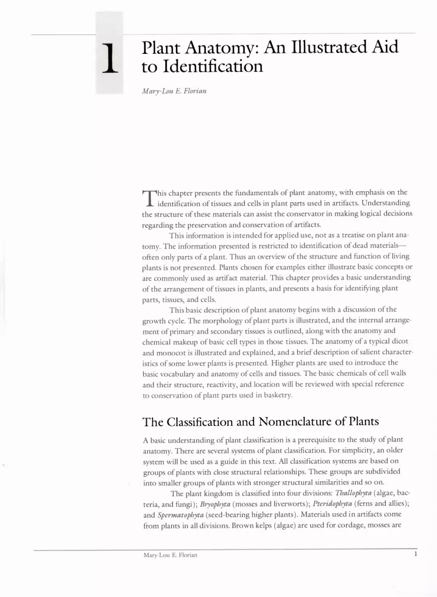
1 Plant Anatomy: An Illustrated Aid to Identification Mary-Lou E. Florian
This chapter presents the fundamentals of plant anatomy, with emphasis on the
identification of tissues and cells in plant parts used in artifacts. Understanding
the structure of these materials can assist the conservator in making logical decisions
regarding the preservation and conservation of artifacts.
This information is intended for applied use, not as a treatise on plant ana
tomy. The information presented is restricted to identification of dead materials
often only parts of a plant. Thus an overview of the structure and function of living
plants is not presented. Plants chosen for examples either illustrate basic concepts or
are commonly used as artifact material . This chapter provides a basic understanding
of the arrangement of tissues in plants, and presents a basis for identifYing plant
parts, tissues, and cells.
This basic description of plant anatomy begins with a discussion of the
growth cycle. The morphology of plant parts is illustrated, and the internal arrange
ment of primary and secondary tissues is outlined, along with the anatomy and
chemical makeup of basic cell types in those tissues. The anatomy of a typical dicot
and monocot is illustrated and explained, and a brief description of salient character
istics of some lower plants is presented. Higher plants are used to introduce the
basic vocabulary and anatomy of cells and tissues. The basic chemicals of cell walls
and their structure, reactivity, and location will be reviewed with special reference
to conservation of plant parts used in basketry.
The Classification and Nomenclature of Plants
A basic understanding of plant classification is a prerequisite to the study of plant
anatomy. There are several systems of plant classification. For simplicity, an older
system will be used as a guide in this text. All classification systems are based on
groups of plants with close structural relationships. These groups are subdivided
into smaller groups of plants with stronger structural similarities and so on.
The plant kingdom is classified into four divisions: Thallophyta (algae, bac
teria, and fungi) ; Bryophyta (mosses and liverworts) ; Pteridophyta (ferns and allies);
and Spermatophyta (seed-bearing higher plants) . Materials used in artifacts come
from plants in all divisions. Brown kelps (algae) are used for cordage, mosses are
Mary-Lou E. Florian 1

Figure 1.1. Leaf shapes.
used as fillers in bedding and textiles, and the colored stems of ferns are used for
decoration in basketry. But the majority of materials, from grass leaves to wood
splints, come from seed-bearing plants.
The Spermatophyta division contains two distinct groups of plants, the
Gymnospermae and Angiospermae:
Gymnosperms include the rare cycads, gnetales, and ginkoes, and the com
mon coniferous trees and shrubs. The wood and inner bark of coniferous trees are
commonly used in artifacts.
Angiosperms-flowering plants-are divided into two classes: Monocoty
ledonae (monocots) and Dicotyledonae (dicots) , based on the presence of one
(mono) or two (di) seed leaves (cotyledons) in the seed. Grasses and yuccas are
examples of monocots; the hardwood of deciduous trees and the bast fibers of
hemp and linen come from dicots. Within each class there are families (Agavaceae,
Compositaceae, and so on) which are subdivided into genera that include individual
plant species. The nomenclature of a plant-for example, Quercus alba (white oak)
gives the genus ( Quercus) and species ( alba) names. The species is the basic unit and
includes plants from common parents, whereas the genus consists of closely related
species, such as Quercus alba and Quercus rubra.
The classification of plants is based primarily on the floral and reproductive
parts and seed structure, which have little application to our need for identification
of artifact materials. But there are some basic anatomical differences among the
groups that assist in identification:
• Thallophytes (algae and fungi) have a thallus, which is a plant body with
out roots, stems, or leaves and without vascular tissue.
• Bryophytes ( liverworts and mosses) have leaves and stems, but do not
have true roots and have limited vascular tissue.
• Pteridophytes (ferns) have stems, leaves, rootlike rhizomes (underground
stems), and well-developed vascular tissue.
• Spermatophytes (seed plants) have stems, leaves, and true roots.
The anatomical structure of spermatophytes shows great variation, but
there are basic differences among groups-for example, the diffuse arrangement of
vascular bundles in monocot stems in contrast to the circular arrangement in dicots.
These and other differences that aid identification are discussed in detail later.
Morphology and Development
Plant Morphology
Morphology is the form or structure of plant parts. For example, some leaves are
thin and long, while others are short and thick (Figure 1 . 1 ) . The morphology of
plant parts often dictates their use in artifacts. However, since morphology can
be difficult to distinguish in retrospect when only parts of a leaf or stem have been
used, it is not very useful to conservators as a characteristic in the identification
of materials.
2 Plant Anatomy

cotyledo n--------.. (shoot)
root ___
axillary bu
� . I . aplCa mertstem of shoot
./ apical meristem At" of root
Figure 1.2. Meristems in three stages of the development of a seed plant.
Figure 1.3. (a) Cross section of a dicot stem. (b) Cross section of a mono cot stem.
Embryonic Development
On germination of a seed, embryonic cells (meristems) divide and differentiate to
form cell clusters that function as a unit called tissue. Meristems are located at the
apex of the roots and stem and also in buds (Figure 1 .2 ) . Cells in plants may vary in
size from 1 0 /J. to 50 /J. (one micron is equal to 1/1000 mm) in width and 1 0 /J. to
50 /J. (or more) in length. The functions of the tissues are to give the new plant me
chanical strength, to adsorb water, and to synthesize and transport food materials
needed for further growth and reproduction.
The body of a seed plant is made up of distinct parts or organs: roots,
stems, leaves, flowers, fruit, and seeds. These organs are composed of different tis
sues, such as metabolic, strengthening, protective, reproductive, and so on. In turn,
tissues are made up of structural and physiological units called cells.
Primary Tissues
Embryonic cells present in the meristems of a seed are active throughout the growth
of a plant. The tissues that are formed from this embryonic activity are called pri
mary tissue. A tissue is a group of cells that function as a unit. The tissues of a
grass plant, for example, are all primary tissues. If the plant is a perennial, new
embryonic tissue (cambium) forms each growing season, giving rise to new tissues
that increase the girth of the plant; such tissues are called secondary tissues. The
wood of a tree, for example, is secondary tissue, but the tissue of the leaves of the
same tree is primary tissue. An understanding of the arrangement and function of
these tissues in the plant aids in the identification of materials and the understanding
of their deterioration.
Primary tissues are found in stems, roots, flowers, and leaves; they are the
tissues of the transport (vascular) , strengthening, outer protective, reproductive, and
metabolic systems. Secondary growth is usually limited to growth in the stem and
roots. There the secondary tissues are found in the transport, strengthening, and
protective systems.
The tissues within a system (e.g. , vascular, strengthening) have specific
names related to their position in the plant organ and to their specific function. In
each tissue there may be a single type of cell or a variety of cells. The tissue names
in the different systems and cell types are listed below as an introduction to the voca
bulary (Table 1 . 1 ) . Descriptions of the tissues and cells in primary and secondary
tissue follow.
b vascular bundles
epidermis
Mary-Lou E. Florian 3

Table 1.1. Primary and secondary plant tissues and their cells.
Figure 1.4. Types of steles: (a) protostele, (b) amphiphloic siphonostele, (c) ectophloic siphonostele, ( d, e) dictyostele.
a
Tissue
Transport system xylem
phloem
Metabolic system mesophyll
cortex (ground tissue)
pith Strengthening
sclerenchyma
collenchyma Protective
epidermis
endodermis periderm (bark)
Growth embryonic
... - . .' ,
I I I I I I I I : I I I I I I I I I I I
,) -+ =---::-r--l v'f .... --�� \ � J J ...... ::::.=::.-
4
b
Cells in Primary Tissue Cells in Secondary Tissue
vessel member tracheid tracheid vessel member protoxylem parenchyma metaxylem parenchyma sieve element sieve element companion cell companion cell parenchyma
chlorenchyma parenchyma aerenchyma parenchyma idioblast tannin cell parenchyma
fiber tracheid tracheid vascular fiber bundle fiber tracheid phloem fiber phloem fiber sclereid sclereid collenchyma
epidermal hypodermal stomatal trichome silica glandular endodermal
phellem phelloderm
meristematic vascular cambium phellogen
c d e
/ -,.....,
Plant Anatomy

Arrangement of Primary Tissues in Plant Parts
The arrangement of these tissues in stems, roots, and leaves, as seen in a cross sec
tion of a mature plant part, is described below.
The Stem
The stem is bounded by a single layer of cells, the epidermis. It is composed of epi
dermal cells, stomata (complexes of cells that regulate transpiration), glandular cells,
and trichome (hair) cells. Inside this outer layer of cells, a layer of hypodermal cells
with specific cell characteristics such as pigment or wall thickness may be present in
some species.
Inside the epidermis is the cortex (or ground tissue) . In some stems, the
outer cortex may contain groups of cells or a continuous ring of cells that function
as support to strengthen the stem. These are collenchyma or sclerenchyma cells. If
the stem is green, there may be specialized cortical cells, chlorenchyma cells, which
have a photosynthetic function. Cells of the cortex commonly contain starch, oils,
crystals, and so on. The central core of the stem contains the vascular tissue, called
the stele. It contains the xylem and phloem tissues and sometimes the central pith
(Figure 1 .3 ) . Sclerenchyma tissue may also be associated with vascular tissue.
The vascular tissue in the stele may take many arrangements, depending upon the
plant species .
Types of Steles: Arrangement of Xylem, Phloem, and Pith
Four main types of steles are present in vascular plants as shown in Figure 1 .4:
• Protostele. The most primitive of the steles, it is composed of a central
solid circle of xylem surrounded by phloem (Figure 1 .4a). There is no
central pith. Protosteles are common in primitive ferns .
• Amphiphloic siphonostele. This has a central pith surrounded by
phloem, then xylem, then another outer circle of phloem next to the
cortex (Figure l .4b) . This stele is common in ferns, but rare in dicots.
• Ectophloic siphonostele . This has a central pith surrounded by xylem,
which in turn is surrounded by phloem (Figure 1 .4c) . It is common in
dicots and gymnosperms.
• Dictyostele. The vascular cylinder consists of a network of separate
strands (vascular bundles) which may appear circular in cross section
(Figure l .4d) or scattered throughout the ground tissue (Figure 1 .4e) .
The circular dictyostele i s found in dicots and the scattered dictyostele
is common in monocots.
Types of Vascular Bundles: Arrangement of Xylem and Phloem
The individual vascular bundles of the stele are classified on the basis of the arrange
ment of xylem and phloem. There are four general types of vascular tissue arrange
ment in the vascular bundle (Figure 1 .5 ) :
• Radial Vascular Bundle. The most primitive of the vascular bundles,
the xylem and phloem occur in separate strands on alternating radii
(Figure 1 .Sa) .
Mary-Lou E. Florian 5

a
b
c
d
e
fj�'� phloem ., f'!l ........ V ---xylem
Figure 1.5. Types of vascular bundles: (a) radial, (b) collateral, (c) bicollateral, (d) concentric amphicribral, (e) concentric amphivasal.
Figure 1.6. (a) Basic tissue arrangement in monocot or dicot leaf shOlVn in cross section. (b) Net venation of a dicot leaf (c) Parallel venation of a monocot leaf
• Collateral Vascular Bundle. This type has separate vascular bundles with
the xylem on the inside and the phloem next to the cortex (Figure l.Sb) .
The bundles are separated by parenchyma cells. Often the protophloem
forms phloem fibers for support. Collateral bundles are characteristic of
the stems of dicots and gymnosperms, occasionally in some ferns, and
rarely in monocots (e.g. , corn) .
• Bicollateral Vascular Bundle. This type of vascular bundle has both inter
nal and external phloem (Figure l.Sc) . It is found in some dicots, for ex
ample in Solanaceae (potato family), Cucurbitaceae (gourd family), and
Apocynaceae (Indian hemp family) .
• Concentric Amphicribral Vascular Bundle. Here the phloem surrounds
the xylem (Figure l.Sd) . Commonly found in ferns .
• Concentric Amphivasal Vascular Bundle. Here the xylem encircles the
phloem (Figure l.Se ) . Commonly found in monocots and dicots.
The Leaf
Structurally, leaves and stems are quite similar. The arrangement of primary tissue in
the stele and the arrangement of vascular tissue in the vascular bundles are the same
in both. Often, only parts of leaves or stems are used in artifacts and their structural
similarity can make identification of the plant part difficult.
Most leaves are dorsoventrally flattened. Between the upper and lower
epidermis lie the mesophyll tissue (photosynthetic palisade mesophyll and respira
tory and spongy storage mesophyll ) and the vascular bundles that form veins. The
arrangement of the vascular tissue follows that given for the stem.
a 1 upper epidermis
_.,-__ '_..r
vascular bundle
__ palisade mesophyll
+--__ spongy mesophyll
\ 10lVer epidermis
b c
6 Plant Anatomy

Figure 1. 7. Arrangement of primary tissue in a typical root.
a pericycle
phloem
xylem
b
protoxylem
metaxylem
c o-�s;::�--protoxylem
metaxylem
d protoxylem
early metaxylem
late metaxylem
Figure 1.8. Different patterns of primary xylem in the stele of roots: (a) diarch, (b) triarch, (c) tetrarch, (d) polyarch.
� root hair
/ outer epidermis
/ cortex
endodermis
phloem
xylem
Leaf structure varies depending upon the environment for which it is
adapted. Monocot and dicot leaves in cross section may appear similar, but there is a
basic difference in the vein structure : In monocots the unbranched veins lie parallel
to one another, while dicots contain a reticulate network of branched veins. The
parallel arrangement of veins in monocot leaves makes them excellent material for
basketry and weaving, because they can easily be split into fine strands while still
retaining fibrous strength.
Leaves have many species-specific characteristics that aid identification.
For general purposes, however, Figure 1 .6 provides a comparison of basic tissue
arrangement in typical, mature monocot and dicot leaves.
The Root
The cross section of a root in Figure 1 .7 shows the arrangement of primary tissues
and the clear separation of the external epidermis, cortex, and vascular system.
The epidermis is specialized for water adsorption and usually has root hairs,
which are single epidermal cells with hairlike extensions. The cortex consists mainly
of parenchyma cells with intercellular spaces. The innermost layer of the cortex is
differentiated into an endodermis, the cells of which contain a waxy suberin band
called the Casparian strip . Within the endodermis is the vascular cylinder with the
outer pericycle and internal xylem and phloem. This stele is a protostele with a
central core of xylem surrounded by phloem.
Primary xylem in the stele of roots can assume different patterns. These are
called diarch, triarch, tetrarch, and polyarch according to the number of arms of
xylem-two, three, four, or many, respectively (Figure 1 .8a,b,c,d) .
Basic Cell Types of Primary Tissue
Identification of basic cell types is essential to the identification of materials used
in artifacts. Often, only minute fragments that have lost their tissue integrity are
available for analysis, and the ability to recognize just one cell may be the key to
identification.
Mary-Lou E. Florian 7

epidermal
�� Figure 1.9. Outer layer of epidermis showing continuous layer of epidermal cells.
Figure 1.10. Epidermis of a grass leaf showing stomatal complex and epidermal cells. (a) Cross section of epidermis showing stomatal complex. (b) Surface view of epidermis shOlving stomatal complex.
Figure 1.11. Surface view of epidermis of different plants showing variation in stomatal complex.
Epidermis
The epidermis constitutes the layer of cells that covers the plant body. The cells take
on specific functions, as reflected in their structure. There are protective waxy epider
mal cells, guard cells that regulate transpiration or air and water vapor exchange,
and glandular and hair cells. The continuity of the epidermis is interrupted by the
minute openings of the guard cells, called stomata.
Structure of the Epidermal Cell
The cell wall of waxy epidermal cells is usually thickened on the surface . The waxy
material is called cutin; it often forms a waxy bloom or cuticle on the exposed sur
face of the cell wall. Pectic substances glue the cuticle to the cell wall. The functions
of the wax are waterproofing, ultraviolet and infrared reflectance, and protection
from microorganisms.
The epidermal cell may be colored due to the presence of tannins and plant
pigments. In Figure 1 .9, the structure of the outer epidermis shows a continuous
layer of similar epidermal cells.
Stomatal Complex
Stomata are openings in the epidermis. They are surrounded by specialized epider
mal cells called guard cells that regulate the size of the opening or stoma. The
complex of the stoma and two guard cells is called a stomatal complex (Figure
1 . 10 ) . Sometimes epidermal cells adjacent to the stomatal complex differ in shape
from other epidermal cells; such cells are called subsidiary cells (Figure 1 . 1 1 ) . The
arrangement of the guard cells and the subsidiary cells is an aid to identification of
plant groups.
Special Types of Epidermal Cells
Other types of cells are found in the epidermis, such as glandular and hair cells.
Some epidermal cells may contain silica or cork. A few of these are illustrated in
Figure 1 . 1 2 .
a epidermal cell subsidiary cell
��
g
�
uar
�
d"\1� b stoma
\I IJ/i�-I}..I-guard cell
subsidiary cell
epidermal cell stoma
a c
8 Plant Anatomy

Figure 1.12. Special types of epidermal cells: (a) uniseriate hair, (b) stellate hair, and (c) stalked glandular hair.
Figure 1.13. Parenchyma cell characteristics. (a) Parenchyma cell structure. (b) Phytoliths in bulrush parenchyma cell. (c) Parenchyma cell shape specialized for buoyancy.
a b c
Parenchyma Cells
The basic cell type of the metabolic system is the parenchyma cell. It is a thin-walled
cell and functions to produce or store starch, pigment, oil, crystals, and tannin.
Newly formed parenchyma cells contain a living protoplast (Figure 1 . 1 3a) .
Contents of Parenchyma Cells
Cell contents can be an aid to identification. For example, the parenchyma cells of
the leaf of the bulrush Typha latifolia L. contain crystal-like phytoliths that are
readily seen under the microscope (Figure 1 . 1 3b) .
Parenchyma Cell Shapes
Parenchyma cells may assume many different shapes reflecting their function. For
example, leaf cells seen in cross section may be elongate to draw sunlight into the
leaf for efficient photosynthesis. Or parenchyma cells may have a stellate shape to
provide large areas for air, adding buoyancy to leaves commonly associated with
water environments (Figure 1 . 1 3c ) . Such cells are called aerenchyma cells. Often,
the shapes of these cells are also aids to identification.
Vascular Tissue
The primary tissues of the vascular system are the xylem, which transports water
within the plant, and the phloem, which transports metabolic products such as
sugar, acids, and protoplasmic contents. The xylem and phloem cells are associated
with strengthening fibers and living parenchyma cells to form a vascular bundle. The
primary cell types of the xylem are the protoxylem and metaxylem tracheid and ves
sel member cells. The primary cell types of the phloem are the sieve elements and
companion cells.
a primary wall l
Mary-Lou E. Florian
living protoplast
b c
9

a b
c
00 GGOo 0000 0000 000 00 000
DOC) o
Figure 1.14. The tracheary elements; tracheids and vessel members. (a) Tracheid with bordered pits. (b) Vessel member with sclariform perforation plate. (c) Vessel member with simple perforation plate.
Figure 1.15. (a) Cross section of vascular bundle of Zea mays (corn) showing diagnostic arrangement of protoxylem and metaxylem. The firstformed protoxylem cells disintegrate to form a lacuna. (b) Different metaxylem and protoxylem cell arrangement in an Agavaceae.
Xylem Tissue Cells
Tracheary Elements
The tracheary elements of the primary xylem are those cells involved in water con
duction: the tracheids and vessel members. These cells are present also in secondary
xylem. The main differences between secondary and primary xylem are their embry
onic origin and organization. Primary xylem is formed by meristematic tissue and
secondary xylem from the cambium. Primary xylem and associated primary phloem
are organized into strands or vascular bundles, whereas secondary xylem grows in
rings and is a radial as well as longitudinal system.
The tracheids are elongate cells with pits on the longitudinal walls and
angled, closed end walls. Vessel members are usually short, broad cells. There are
pits on the longitudinal walls and the end wall has an opening called a perforation
plate, allowing the formation of a long, continuous tube made up of a number of
vessel members. This structure is called a vessel. Perforation plates may be simple
openings or they may assume a sclariform or ladderlike appearance (Figure 1 . 14) .
The characteristics of the perforation plates and pitting are an aid to identification
of plant species.
Protoxylem and Metaxylem Cells
Primary xylem cells vary in shape according to the sequence of their formation. The
first-formed xylem cells are the protoxylem cells and the next-formed are the meta
xylem cells. The differences in the shapes and relative position of these cells in the
vascular bundle are an aid to identification. There are no definitive studies of the spe
cies commonly found as plant artifact materials, but Figure 1 . 1 5 shows the potential
use of this characteristic for identification.
a sieve tube cell
�������7" companion cells I of phloem
metaxylem vessel
remnant protoxylem vessel
protoxylem lacuna
Secondary Wall of Primary Xylem Cells
b
In addition to a primary wall, xylem cells also have a secondary wall that appears as
annular, helical, sclariform, or reticulate thickenings or pitted elements on the inside
of the primary cell wall (Figure 1 . 16) . These thickenings are aids to identifying the
presence of primary xylem cells. However, because all shapes and an integration of
shapes may be present at a given stage of growth, they do not help with species iden
tification. This is not the case with secondary xylem vessels; their use in identifica
tion is discussed in the section on hardwood.
The primary and secondary cell walls are laid down by the living protoplast
outside the cell membrane. Once the cell walls are completed, the protoplast dies.
10 Plant Anatomy

Figure 1.16. Variety of typical secondary wall thickenings of primary xylem cells: (a) annular, (b,c,d) helical, (e) sclariform, (j) reticulate, and (g) pitted.
a
b
sieve plate
sieve area
companion cell
plate
sieve area
companion cell
Figure 1.17. (a) Longitudinal view of sieve tube showing sieve elements with adjacent companion cell, stIrface sieve areas, and sieve end plate. (b) Cross section of primary phloem showing sieve elements, sieve plate, and adjacent companion cells.
Figure 1.18. Diagram of location of phloem fibers in commercial linen plant stem.
a b c e f g
Thus the mature xylem cells are, essentially, extracellular tubes for the transport of
water and dissolved minerals.
Phloem Tissue Cells
The basic cell types of the phloem are the sieve elements, parenchyma cells, scleren
chyma fibers, and sclereids. The primary and secondary phloem contain the same
cell types, but transport offood (metabolic products) in the axial system of the pri
mary tissue only occurs longitudinally, whereas the axial and radial systems in the
secondary phloem incorporate radial transport as well.
The Sieve Elements
The sieve elements, or sieve-tube members, are long cells with thin primary cell
walls and without a protoplast (Figure 1 . 17 ) . Protoplasm flows into adjacent cells
through sieve areas on the walls of the sieve cells. The distinctive shapes of the sieve
areas are rarely seen in dried artifactual material, because the cells are thin-walled
and collapse during dehydration of the proteinaceous cell contents. Comparative
anatomy studies show that gymnosperms and lower plants have sieve cells with sieve
areas along the length of the cell walls, whereas angiosperms have sieve areas only at
the end walls of the cells. The sieve cells do not have a protoplast; adjacent living
companion cells in angiosperms contribute the necessary materials for functioning.
Sclerenchyma Phloem Fiber Cells
Fibers are commonly located on the outside of primary phloem. These cells are
long, with thick walls, and are used as commercial fibers (for example, Linum,
Cannabis, Apocynum) . Sclereids may also be associated with phloem, and are an
aid in identification (Figure 1 . 18 ) . Details ofsclerenchyma fibers and sclereids are
discussed in the section on primary supporting tissue .
epidermis cortex
sclerenchyma phloem fibers
phloem
cambium xylem
Mary-Lou E. Florian 1 1

Figure 1 .19. Collenchyma cell shape and distribution: (a) cross section of collenchyma tissue showing unevenly thickened walls of cells, (b,c) cross section of stems showing typical distribution of collenchyma (dark area) in stems, and (d) in a leaf
a
b
Figure 1 .20. Sclerenchyma cell (a) fibers and (b) sclereid.
a
LePidermis
.. b d
Primary Supporting Tissue
Collenchyma
The collenchyma cell has relatively soft, pliable primary walls and an active proto
plast. The cell walls are rich in pectic substances and hemicellulose, which allow
them to swell to a turgid state for strength. The wall is not lignified. To make a
drooping celery stalk crisp, for instance, placing it in water will allow the collen
chyma cells to adsorb water and become turgid. The cell walls are unevenly thick
ened; the thickest region is at the corners between cells (Figure 1 . 19a) .
Collenchyma is located either directly beneath the epidermis or one or
two cells below it. In stems it may form strands, ribs, or a continuous ring of tissue
(Figure 1 . 19b,c ) . In the leaf blade it is associated with the midrib on the ventral and
dorsal regions (Figure 1 . 19d).
Sclerenchyma
Sclerenchyma tissue is composed of cells with thick secondary walls. Sclerenchyma
cells generally take two forms-long, slender cells called fibers and isodiametric cells
called sclereids-but there is a wide range of transitional forms (Figure 1 .20a,b).
The walls of these two sclerenchyma cells show strong birefringence (the ability to
refract light) under crossed nicols using polarized light.
Sclereids
Sclereids (Figure 1 .2 1 ) are usually found as isolated cells in a tissue and, because
they differ so much in form and size from other cells, are called idioblasts. They may
occur in the ground tissue, epidermis, and vascular system and vary greatly in shape.
Sclerenchyma Fibers
Like the sclereids, sclerenchyma fibers are found in many plant parts. The fibers are
long, with strong secondary walls. Usually they occur in bundles and are widely
used commercially. The ends of the long fibers in a bundle overlap, adding strength
(Figure 1 .20) . In commercial applications, individual fibers or fiber bundles may
be used, depending on the degree of fabrication. In dicots, sclerenchyma fibers are
commonly associated with stem vascular bundles such as phloem (bast) fibers
(Figure 1 . 1 8 ) .
The individual fiber cells in longitudinal view show the thick secondary
wall, the central lumen of the cell, and characteristic nodular markings along the
length of the fiber. These markings are often species specific and aid in identification
of fibers. Common sclerenchyma phloem fibers used in artifacts include the hemps,
linen, milkweed, stinging nettle, ramie, and jute (Figure 1 .22 ) .
1 2 Plant Anatomy

Figure 1.21. Examples of sclereid shapes: (a) stem, (b) leaf, (c) fruit, (d) seed coat in surface (upper) and longitudinal (lower) view.
Figure 1.22. Longitudinal view of individual fibers from Linum usitatissimum (linen) showing characteristic nodular markings and central lumen.
a b c d
• In monocots, leaf fibers may enclose a vascular bundle like a sheath or form
caps on one or both sides of the bundle. This is detailed in the section on monocot
leaves . The sclerenchyma leaf fibers of monocots are commonly used as fibers in
artifacts and commercial goods (manila, agave, pineapple fibers, sisal, and so on).
The sclerenchyma vascular bundle sheaths or caps are retted out or pulled mechani
cally from the leaf tissue .
Secondary Tissues
Secondary tissue is found in trees, both dicotyledons (hardwoods) and gymno
sperms (softwoods) , as well as in bushes and shrubs. Occasionally secondary tissue
is produced in some large biennial plants.
The secondary tissues are formed during the second phase of plant growth,
which increases the girth of the primary plant body. Primary tissues are formed from
embryonic cells called apical meristems, which are located at the tips of the shoots,
roots, and buds, while secondary tissues are formed from new embryonic cells in
stems and roots called cork cambium and vascular cambium.
The vascular cambium is located between the xylem and phloem, within
the vascular stele, and produces new secondary xylem and phloem. Cork cambium is
located in the outer cortex and produces a periderm of mainly bark or cork cells,
which take the place of the epidermis.
Secondary xylem is what we call wood. Secondary phloem is often called
the inner bark, and periderm is the true bark. Both primary xylem and phloem,
as previously described, consist of cells running longitudinally. The secondary
xylem and phloem have these longitudinal cells but also have cells that radiate
outward from the central axis of the plant body. These cells make up the xylem or
phloem rays.
Primary and secondary cells are similar in function, and the same basic cells
are present, but the tissue organization is different. Because the secondary tissue has
a three-dimensional structure, it is necessary to view all three sides in order to under
stand the complete organization of the tissue and structure of the cells. To do this,
wood is sectioned on three surfaces:
• cross (or transverse) section, taken across the long axis of the stem;
• radial section, a longitudinal section taken on the radius of the circular
stem or root;
• tangential section, a longitudinal cut on the tangent of the circumference
of the circular stem or root.
Mary-Lou E. Florian 1 3

Figure 1.23. Three-dimensional aspect of tree Ctmnk or woody stem.
Organization of Secondary Tissues in a Woody Stem
The three-dimensional diagram of a woody stem in Figure 1 .23 shows the arrange
ment of the outer bark, secondary phloem, cambium, and secondary xylem on the
transverse surface.
The secondary xylem (wood) has two distinctive features: ( 1 ) annular
growth rings that represent the amount of tissue formed in one growing season,
and (2 ) different cell wall thicknesses at the edges of these rings . The thin-walled
cells of early wood tissue are formed in the spring, during the rapid growing season,
and the thicker-walled cells of late wood at the end of the growing season. The
central region of the wood may appear darker in color than external wood. The dark
central region is wood in which colored resins, tannins, phenolic materials, and
other substances, have been deposited to waterproof the wood and make it resistant
to decay. This central wood is called heartwood. The outer region of wood adjacent
to the cambium is lighter in color; in life it has a higher water content and stores
carbohydrates such as starch. This is called sapwood.
Secondary phloem forms on the outer side of the cambium. In some older
tree trunks, such as western red cedar, yellow cedar, and some Eucalyptus species,
this is the most external tissue and is incorrectly called bark. The secondary phloem
also shows annular growth rings, but not as distinctly as in the wood. The thickness
of this tissue varies with the species .
The periderm, when present, is the outside tissue of the stem. This tissue is
composed of the circular bands of outer phellem or bark cells, the middle cork cam
bium or embryonic tissue, and inner phelloderm cells or secondary cortex. On the
transverse and radial surface, the parenchyma cells of the wood and phloem rays are
seen as continuous lines of cells running out on radii of the circular stem. The wood
and phloem rays run continuously through the xylem and phloem. On the tangen
tial surface the rays are seen as individual cells in cross section. The shape of these
rays varies with species . All the cells of the secondary tissue have secondary walls
with the exception of the parenchyma ray cells.
wood (secondary xylem)
rays �]i."'�!--cambium
outer
inner bark (living tissue of secondary phloem)
14 Plant Anatomy

a b
pits
Lariform perforation plate
bordered pits
Figure 1.24. Comparison of (a) a tracheid and (b) a vessel member.
Figure 1.25. Fiber tracheids of dicot wood in (a) longitudinal view and (b) cross section.
Secondary Xylem
Cell Types
The three cell types of secondary xylem include ( 1 ) the water-conducting tracheary
elements, the tracheids and vessels; (2 ) supporting fibers; and ( 3 ) the metabolic
tissue, ray parenchyma cells.
Tracheary Elements
The fibers of wood pulp paper are familiar to most everyone. Here the word fiber is
used to refer to all the wood cells, most of which are tracheary elements. Tracheids
are the main tracheary cells of softwood, and vessel members are the main tracheary
cells of hardwood. Thus tracheids and vessel members serve to distinguish the two
types of pulp paper. The most significant difference in the two types of cells is that
the vessel members are open at the ends, which have perforation plates allowing free
movement of water from one cell to another, whereas the tracheids lack perforations
or open-ended walls . The column of vessel members is called a vessel. The morphol
ogy of the perforation plate is used for identification of hardwood species (Figure
1 .24) . The water moves from one tracheid to another by bordered pits on their
radial walls. The bordered pit is made up of pit pairs on the secondary walls of two
adjacent cells, which bulge out like two inverted saucers. Between the pits is the
middle lamella complex, which acts as a valve membrane to open or close the pits.
The presence of bordered pits always indicates a gymnosperm wood. There are also
pits on the radial walls of vessel members, but they do not have the complex bor
dered pit of the tracheids. The size, arrangement, and morphology of these pits are
used to aid identification of hardwood species.
Fiber Tracheids
Fiber tracheids are fiberlike tracheids in the secondary xylem of hardwoods (dicots ) .
They differ from softwood tracheids in having thicker walls and pits with lenticular
openings rather than circular openings. The secondary cell wall may be lignified and
in dicot reaction wood the cells are rich in gelatinous hemicellulose and are called
gelatinous fibers (Figure 1 .25 ) .
Parenchyma Cells
The parenchyma cells vary considerably in shape and cell content. The wood rays
are made up of groups of parenchyma cells that are species-specific in cell size and
arrangement. Within the rays the parenchyma cells may be of two different types
(heterocellular) , either procumbent or upright in orientation, or they may all be
the same (homocellular) . The ray cells have simple pits joining them to adjacent
tracheids and vessels.
Comparison of Softwood and Hardwood Structures
The following are only a few of the salient anatomical differences of wood that are
used as aids to identification. Identification keys are given in the references. The
keys are usually dichotomous keys, which means that at each step there are two
choices-that is, the presence or absence of a specific characteristic. If the character
istic is not present, then one proceeds to the next two alternatives .
Mary-Lou E. Florian 1 5

Figure 1.26. Transverse section of secondary xylem showing a resin canal lVith (a) thick-walled epithelial cells and (b) thin-walled epithelial cells.
Figure 1.27. Types of pit pairs occurring in the cross fields of coniferous woods: (a) piceoid, (b) cupressoid, (c)taxodioid, (d,e) fenestral pinoid.
Figure 1.28. Variation in size and distribution of vessels in hardwood growth rings: (a) diffuse poroltS with late wood vessels smaller than early lVood, (b) diffuse porous with late and early wood vessels similar in size, (c) ring porous.
b
tracheid r -���r-resin canal ,
},r ��� � R� ' tf1 ��
I)- � �
thin -walled epithelial cell
rr��;;���QL thick-walled P-epithelial cell
a b c II II � II :: @ @ :: it � � I: II II � II
a b
II II ::100:: II II
II II
d
:101: II II
ii ii c
I-
e
::80:: :: on II II
Softwood ( Coniferous Wood)
All softwoods have tracheids; no vessels are present. Bordered pits are present on the
radial walls of the tracheids.
The following features vary with softwood species:
• Resin canals may be present or absent; epithelial cells, secretory cells that
produce resin, may be thin- or thick-walled (Figure 1 .26) .
• Pitting in field crossings of ray parenchyma cells and tracheids may
be one off our types (piceoid, cupressoid, taxodioid, and fenestral) ,
illustrated in Figure 1 .27.
• Ray tracheids, thick -walled cells that run radially along the outside of the
ray parenchyma and have bordered pits and no protoplast, may be pres
ent or absent.
Hardwood
All hardwoods have vessels and thick-walled fibers. The arrangement and variation
in size of the vessels are features used for identification. Within a growth ring the
vessels may be all one size or may vary in size from large early wood vessels to small
late wood vessels (Figure 1 .28 ) . The vessels may be distributed evenly throughout
the growth ring (diffuse porous) or concentrated along the beginning of a growth
ring ( ring porous) .
Perforation plates are of various shapes. The perforation plate may be a
simple opening (simple) or the plate may have parallel bars of various thicknesses
(sclariform) across it (Figure 1 .29) .
16 Plant Anatomy

Figure 1.29. Variations in perfora-tion plates of vessel members: (a,b) simple perforation plates, (c,d,e) variations in sclariform perforation plates.
Figure 1.30. Pitting patterns on ves-sel radial walls: (a) sclariform, (b) opposite, and (c) alternate.
Figure 1.31. Hardwood ray shapes and cell arrangements: (a,b) long and short homocellular rays (tan-gential), (c) biseriate heterocellular ray (tangential), (d) multiseriate homocellular ray (tangential), (e) homocellular ray (radial), and (f) heterocellular ray (radial).
a b
a b
a b
� �� - - <£> . ��
C!D(g)CiD c:E>�� GE>=
�<D _<!Dca:>
c
c
c
d
d e
co i 0 � 0 8 0 � 000 - q
000 3S 00 == l �'i= sr : ..
I . -
e f
Pitting on vessel walls varies in size, shape, and pattern. The pits may be
circular, oval, or sclariform; they may be arranged in rows opposite or alternate to
each other in the adjacent row (Figure 1 .30) .
Tertiary wall thickenings are described and illustrated in Figure 1 . 16 .
Hardwood rays vary in size and arrangement of cells (Figure 1 .3 1 ) . The
hardwood rays may be one cell wide (uniseriate) or made up of two (biseriate) or
many cells (multiseriate) in width. The parenchyma cells may be all one shape
(homocellular) or made up of different shapes (heterocellular) .
Comparison of Trunk, Branch, and Root Tissues
The basic cells and organization of the tissues in the wood, branches, and roots of
deciduous and coniferous trees are the same. The same cellular characteristics used
to identifY wood species are in the trunk, branches, and root. The differences in the
tissues are in the size and number of cells. Even though the trunk is circular, wood
tissue seen under a microscope will show a horizontal and vertical arrangement of
cells because the cells are large and the growth ring curvature is lost in the small
fragment. Artifact materials generally utilize small roots and branches, so the curva
ture of the growth rings is prominent. In branches, the wood is denser and cells
are smaller and have much thicker walls than in roots, whereas root tissue is more
porous and contains a larger number of parenchyma cells and resin canals than
branch wood (Figure 1 .32) .
Mary-Lou E . Florian 1 7

Figure 1.32. Comparison of trunk, root, and branch wood (xylem) seen in cross section at the same magnification. (a) Trunk wood shows vertical and horizontal arrangement of cells and only one growth ring. (b) Root wood shows curvature of many growth rings, large, thin-walled tracheids and many parenchyma wood rays. (c) Branch wood shows growth-ring curvature and small thick-walled cell and central pith.
Figure 1.33. Three-dimensional structure of secondary phloem of western red cedar showing layers of fibers between two sieve elements and a parenchyma cell. (a) Transverse, (b) radial, and (c) tangential views.
a b c
Secondary Phloem
The primary and secondary phloem contain the same cell types (see section on
primary phloem tissue cells) . The cell types of the secondary phloem are the sieve
elements and the companion cells of the sieve elements, the sclerenchyma fibers, the
sclereids, and the parenchyma cells (longitudinal and ray) . Coniferous phloem and
clicot phloem are similar in structure . They are composed of alternate layers of fibers
separated by sieve element cells and parenchyma cells (Figure 1 .33 ) . The presence of
the thin-walled parenchyma cells adjacent to strong fibers allows the tissue to sepa
rate easily into sheets of cells. This is the reason that it is used as a fibrous material in
artifacts. The newly formed secondary phloem adjacent to the vascular cambium is
living tissue and the cells are functional in food storage and transport. Older second
ary phloem that has taken over the function of protective bark has gone through
cellular changes. The fibers remain the same size and shape, the sieve elements col
lapse, but the parenchyma cells enlarge and produce tannin and polyphenolics to
waterproof the tissue. This older secondary phloem fragments easily and is not used
in making artifacts.
sieve members
,r.��-companion parenchyma cell
b
c sieve area on sieve elemen r 0 parenchyma
1 8 Plant Anatomy

Figure 1 .34. Three-dimensional diagram of the cork cells of the phellem of birch. The long axis of the cells is around the tree trunk.
Figure 1.35. Transverse surface of trunk of large coniferous tree shOlving irregular rhytidome of the bark.
tangential
Periderm
0 '
" l I
, ' , I
radial
The periderm is the protective bark of secondary origin. The basic cells of the peri
derm are the cork cambium, which is embryonic tissue that gives rise to the phellem
cells toward the outside and phelloderm cells toward the secondary phloem. Phel
lem cells are commonly called cork cells. Phelloderm cells are parenchyma cells. All
barks contain the same cells, but there are differences in cell size and arrangement
that aid in identification.
Cork cells of the phellem are heavily suberized cell walls. Suberin is a waxy
substance whose chemical characteristics are discussed in the section on the chemis
try of cell walls. Tannins give the brown-to-red color to the cell walls of certain
trees-for example, cherry bark. The phellem develops in growth rings similar to
wood. The thick-walled late cells adjacent to the thin-walled early cells are weak
points that allow the bark to exfoliate off a tree trunk, as in birch bark (Figure 1 .34).
It is only the phellem of the periderm that is used for decoration and construction
of artifacts. Some of the conifers and eucalyptus trees lose the periderm after the first
years of growth, and the secondary phloem takes over the function of the bark.
In some old coniferous trees, such as pines, the periderm is made up of old
dead tissue that is irregular and corky and is called the rhytidome (Figure 1 .35 ) .
Mary-Lou E. Florian 19

Chemistry and Structure of the Cell Wall
A basic understanding of the chemicals in the cell wall is necessary to understand
the reasons for the use of specific plant materials in artifacts, as well as their inherent
weaknesses and reactions with conservation treatments. Many conservation treat
ments use chemicals that could dangerously alter the chemicals in the cell walls and
cause further deterioration. Even such a simple treatment as washing with water
may have deleterious effects on some water-soluble materials. Thus a knowledge
of the chemicals in plant materials is necessary before logical treatments can be
devised. The majority of the following text on the chemistry of the cell wall has
been excerpted from an article by the author (Florian 1987), but the emphasis has
been altered for this manual.
The Chemicals of the Cell Wall
Cellulose
Location
Cellulose microfibrils are embedded in an amorphous matrix of hemicellulose,
pectin, small amounts of protein, and sometimes lignin in primary and secondary
cell walls.
Structure and Organization
Cellulose is a carbohydrate polymer made up of glucose monomers in long,
chainlike molecules. Many of these long chains form fibrous polymers that involve
different levels of organization (molecules, macromolecules, microfibrils,
macrofibrils) .
The mechanical strength of cellulose is a result of the strong bonds between
the glucose units, the great length of the molecules, and the strong intermolecular
bonding of the macromolecular chains. Cellulose is a highly polar polymer. This
means that one side of the molecule is negatively charged and the other side is posi
tively charged. This explains the strong intermolecular bonding.
Crystalline and Amorphous Regions
Cellulose has regions called micelles in which the long cellulose molecules fit tightly
together over a long region and are held strongly together by their own hydrogen
and other secondary bonds. The micelles are the crystalline regions of the molecule .
The long cellulose molecules may pass through the micelles into an amorphous
region where the cellulose chains are not held together but lie more or less at
random. Solvents and enzymes rarely can penetrate micelles, whereas they may
easily penetrate the randomly oriented molecules in the amorphous region. Mate
rials that penetrate the amorphous regions are readily bonded to the available hydro
gen's dipolar and secondary bonds, and cause swelling, chemical reactions, and
even dissolution of the cellulose. The more micellar the regions, the more insoluble
the chemical.
20 Plant Anatomy

Hydration and Swelling
In hydrated cellulose, water molecules are held by secondary force but most abun
dantly by chain segments in amorphous regions causing swelling. Dry cellulose is
inflexible or brittle, but cellulose with 12% moisture content (MC) at 60% to 80%
RH is quite flexible. Water therefore acts as a plasticizer for cellulose .
In most dehydrated organic colloids, rehydration is possible . But with
waterlogged cellulose, the strong intercellulose bonds bring the molecules tightly
together during dehydration, eliminating moisture and causing extreme shrinkage;
this makes it impossible to rehydrate. One of the greatest problems with conserva
tion of cellulosic materials is how to retain sufficient moisture between the cellulose
molecules to retain flexibility and prevent extreme shrinkage .
When swelling is extreme, the micellar structure is destroyed and the cellu
lose is no longer Clystalline. The change from crystallinity to amorphous state can be
observed by polarized light. Crystalline regions show positive birefringence, the
ability to refract light, while amorphous regions have negative birefringence.
A simple demonstration of the crystalline state of cellulose can be made by
using two sheets of polarizing film, one placed between the source of light and the
microscope and the other between the object and the eye. The light passing
through the polarizing film vibrates in only one plane . If the two polarizing ftIms
are at right angles to each other with regard to their plane of polarization, no light
penetrates and the field in the polarizing microscope appears dark. If a crystalline
structure such as cellulose is placed between the two polarizing films, some light
reaches the eye. Because of its crystalline nature and the associated property oflight
refraction, the cellulose changes the plane of polarization of the light that reaches
the polarizing film above the objective and thus permits some light to pass through
it and enter the eye.
Extreme swelling of cellulose may occur in strong alkaline solutions ( 1 0%
to 22% KOH) . Under these extreme conditions, cellulose may swell enormously but
will not dissolve. On drying, this cellulose adopts a different crystalline state called
Cellulose II, as compared to native Cellulose I .
Effect of pH and Salts on Swelling
Research on the role of pH and salts on the swelling of wood pulp and superabsorb
ent cotton shows that the swelling is greatest at about neutrality and is depressed at
both low and high pH values. At all pH values, swelling is further reduced by the
presence of salt. This phenomenon is due to the osmotic gradient caused by the
presence of bound ionizable groups in the macromolecular network of cellulose. In
pure water, they are in excess in the cellulose; thus the water moves in to satisfY the
osmotic gradient, causing swelling.
Extreme pH values release bound ionizable groups, thus changing the
osmotic gradient and reducing swelling. The addition of neutral salts equalizes the
osmotic gradient and also reduces swelling.
Mary-Lou E. Florian 2 1

In reference to conservation treatments of plant fiber materials, if such mate
rials are placed in deionized or fresh water, excessive swelling may occur. Such swell
ing may cause irreversible bond breakage and deformation of the cellulose fibers,
giving them weaker mechanical strength and greater chemical solubility.
It is interesting to note that in the paper industry the use of reduced absorp
tion at low pH has recently been exploited to produce both an economical drying
process and a conversion of the acid groups of sulfite and kraft pulps from the free
acid to the sodium salts, which results in a 20% to 30% increase in the tensile
strength of the paper. Certainly this information has some implications for conserva
tion of cellulosic materials.
Depolymerization of Cellulose
Cellulose can be depolymerized and broken into soluble monomer units only under
extreme conditions. This process may occur very slowly by oxidation, acid hydro
lysis, or gamma radiation. Its rate may be increased by moisture, high temperature,
and light.
Biodeterioration
Enzymatic degradation does occur readily with cellulytic bacteria and fungi, but the
microorganisms require condensed or free water for growth. In wood, microscopic
analysis of the damage shows bacterial pitting and fungi digestive troughs in cell
walls aligned along the angle of deposition of the cellulose macrofibrils and in bor
dered pits. The cellulose has been enzymatically dissolved. This would cause local
physical weakening of the cell wall. Brown rot fungi of wood enzymatically remove
all the cellulose and leave the brown lignin; hence the name brown rot.
Lignin
Location
Lignin is found only in cell walls of land plants, and most commonly in perennial
plants. It imparts rigidity to the cell wall, providing strength for upright growth.
Lignin makes up 1 5% to 35% of the chemical constituents of supporting tissue and
60% to 90% of it is located in the middle lamella primary wall complex. Lesser
amounts are located in the secondary and tertiary walls.
Lignin in cell walls varies in amount depending on the cell or tissue type
and species origin. For example, 19% to 25% is present in hardwood fibers and 25%
to 30% in softwood fibers. Epidermal hairs such as cotton hairs and collenchyma
cells (a primary mechanical tissue) may not contain any lignin. Along with hemicellu
loses and pectins, lignin fills the interstices between cellulose microfibrils. It appears
that, because of its insolubility, lignin is chemically bound to the hemicelluloses .
Lignin and carbohydrate polymers in the cell wall protect each other by blocking
solvents-or at least retarding their entrance. In woods with hemicellulose loss, the
lignin is exposed to chemical change. Analysis of waterlogged woods usually shows a
decrease in hemicelluloses . Lignin is extremely persistent; it has been found in nearly
normal amounts, although chemically altered, in 100-million-year-old wood from a
land burial site. Lignin is the precursor of coal.
22 Plant Anatomy

Structure and Organization
Lignin is composed of a group of similar, very large amorphous aromatic polymers
with little opportunity for cross-linkage or crystallinity. Because it cannot be ex
tracted from cell walls without chemical alterations, the exact structure of native or
first-formed protolignin in cell walls is not known. Because of differences in their
molecular structures, lignins are divided into three categories: softwood, hardwood,
and grass or annual plant lignin.
Reactivity
Lignin is a highly reactive substance, with free groups (hydroxyl, methoxyl, and
carbonyl) that readily undergo bonding. In the analysis of many ancient woods,
extracted lignin shows an increase in methoxyl content over modern wood.
Solubility
Lignin is insoluble in water and is less hygroscopic than cellulose or hemicellulose.
It is sensitive to alkaline degradation.
Physical Characteristics
Lignin imparts rigidity to cell walls, but abnormally high amounts in cell walls cause
brittleness. Lignin is thermoplastic: it softens at 80 ·C to 120 ·C and liquifies at
140 ·C to 145 ·C. Chemically altered lignin loses its thermoplastic qualities.
Hemicellulose
Location and Function
Hemicelluloses are located in all layers of the cell wall. They are concentrated in
primary and secondary walls mixed with lignin and cellulose and are also present in
the cellulose-free middle lamella associated with lignin.
Exactly how hemicellulose associates with cellulose is not completely clear,
but it is considered to be found in cell walls in more or less intimate association with
cellulose. Lignin bonds chemically to hemicellulose but not to cellulose. It appears
that hemicellulose is a protective colloid acting as a hydrated amorphous matrix
surrounding cellulose fibrils, preventing aggregation, hydrogen bonding, and
cocrystallization of the cellulose fibers.
Removal of hemicelluloses has been shown to increase the crystallinity of
fibers, indicating increased cellulose-cellulose bonding. Cellulose-hemicellulose as
sociation is flexible, whereas cellulose-cellulose bonding is rigid, with low strength
properties. In the paper industry, pulp with hemicellulose has greater wet strength;
it is also used for surface finishing of some papers.
The amount of hemicellulose in cell walls varies with the different cell types
and plant species. For example, the hemicellulose content in wood (xylem) is 25% to
40%, in jute fibers 25%, in cotton hair 1 %, and on ivory nut cell walls 90%.
Mary-Lou E. Florian 23

Structure and Solubility
Hemicelluloses are amorphous carbohydrate polymers. They are short chains,
usually branched structures, without microfibrillar structure. They consist of a
mixture of several different monomers or residues ( the pentose sugars, D-xylose,
D-mannose, D-glucose, D-galactose, L-arabinose) and uronic acids (4-0-methyl
D-glucuronic acid, D-glucuronic acid + D-galacturonic acid) . The amounts and
selection of the residues vary with plant species. The characteristic feature of all
hemicelluloses is the presence of the acidic D-glucuronic + D-galacturonic acid
residues. The uronic acids allow large amounts of water to be absorbed during
hydration. They have a similar role to hylauronic acid in animal tissue and the acids
in pectin.
Hemicelluloses are soluble in alkaline conditions and some of the low
molecular-weight polymers may be extracted by water. They are readily hydrolyzed
by acids and the enzymatic activity of bacteria and fungi.
Pectic Substances
Location and Function
Pectic substances are located mainly in the middle lamellae and primary wall . The
amounts of the pectic substance vary greatly with cell types. For example, wood
(xylem) contains 0.5% to 1 .5% (of dry weight), bark 7% to 30%, cotton (primary
wall) 9%, and collenchyma (supporting cells in stems and leaves) 45%. Pectic sub
stances are hydrophilic and act as a molecular colloid in cell walls. They can form
gels; the rigidity of the gel depends on the length of the polymer. They form a part
of the continuous amorphous matrix between cellulose microfibrils in primary walls.
They give rigidity to cell walls, acting as both intercellular cement and cement be
tween the amorphous cuticle and the surface of epidermal cells. For plant parts, such
as leaves, commonly used in artifacts, the intercellular cementing feature of the pec
tic substances is of utmost importance. Loss of the pectic substances may cause loss
of tissue integrity and the cuticle. The pectic substances may also play an important
role in permeability of the cell wall to ions. In vivo studies show that Na, K, Ca, Fe,
and P04 are absorbed in the pectin-like substance of the cuticle.
Structure and Reactivity
Pectic substances are linear polymers made up of polygalacturonic acids and are usu
ally called polyuronids . They are negatively charged and acidic in nature. Pectic sub
stances are a group of related substances (protopectin, pectin) . The terminology of
these substances depends on their solubility and chemical structure .
Protopectin is the native first-formed pectic substance in plant tissue . It is
water insoluble and probably derives its insolubility from being complexed with cal
cium ions. It can be dissolved by using sequestering agents or calcium binders such
as ammonium oxalate in acid and also by hot dilute alkaline conditions.
Pectin is soluble in warm water and, on cooling, is capable of forming gels,
as in jam or jelly. Pectin is made of two chemically different acids, pectic acid and
the more abundant pectinic acid. The primary difference between the two is in the
amount of methoxyl side chains, which are formed on changing the COOH group
to COOCH3 group. Pectic acids are low in methoxyl content, insoluble in acid, and
24 Plant Anatomy

form insoluble salts (pectates) with metal ions. The more abundant pectinic acid is
high in methoxyl content, is soluble at low pH, and forms soluble salts (pectinates)
with metal ions.
The pectic substances may be bound to the insoluble protopectin by cova
lent or secondary bonds with each other or other cell wall polymers, calcium bind
ing, or mechanical intermeshing of filamentous polymers of pectic substances with
other cell wall polymers.
The pectic substances can be readily hydrolyzed by acids and enzymes.
Many bacteria and fungi are capable of using them as nutrients. The retting of flax,
hemp, and jute to make free fibers and the pounding of logs to make them more
permeable to impregnation treatments depend on bacterial hydrolyses of the pectic
substances.
Water-soluble pectic substances may be coagulated by ethanol or acetone
and lose their water-binding capacity. They are also soluble in warm glycerol.
Protein
The protein in the cell walls is not the protein of the living protoplast but a struc
tural protein, a hydroxyproline-rich glycoprotein called extensin.
Collagen, the fibrous protein of leather, is also rich in hydroxyproline . This
similarity of these two proteins makes an interesting case for a common ancestry.
Extensin is found in primary cell walls from 1% to 5% of dry weight. An integral part
of the cell wall, it has been suggested that extensin is a structural protein involved in
cell wall plasticity during growth (hence its name), that it limits swelling of cell
walls, and that it may impart rigidity to the cell walls by cross-linkage with cellulose.
The loss of this protein certainly must influence the strength characteristic of the
cell wall.
Suberin and Cutin
Suberin and cutin are not structural polymers; they are the polymers that provide
the basis of the protective covering of the weather-exposed surfaces of higher plants,
such as the cuticle of the outer epidermis ofleaves, stems, and fruit, and the sub
erized cork cells of bark. They are amorphous hydrophobic materials composed of
polyesters of glycerol esters of hydroxy-fatty acids. Each contains different types and
homologs of these acids. Suberin has a longer chain length than cutin. Suberin is
deposited in lamellae inside the primary cell wall, whereas cutin is deposited extra
cellularly on the outer surface of epidermal cells.
Wax and tannin may also be associated with both polymers. The tannins are
water soluble, the waxes are soluble in organic solvents, and the suberin and cutin
are soluble in boiling alcoholic alkali. Suberin is more soluble than cutin. It may be
saponified at room temperature by alkali and is soluble in hot glycerol. Cutin and
suberin are extremely persistent in nature. In precambrian sediments, the nonhydro
lyzable fraction is shown to contain the cutin-suberin group.
Mary-Lou E. Florian 25

Editor)s Note: Artifacts comprised of parts of deciduous trees and shrubs have two very important
diagnostic features that allow their identification when the plants are not in leaf.
These features are evident on the branches and persist on bark stripped from the
tree or shrub. Lenticels are spongy areas in the cork surfaces of stems and branches
that allow an exchange of gasses between internal tissues and the outer atmosphere.
Transpiration also occurs through these pores as the loss of water as vapor. In young
stems these are represented by stomates ( stomata) , and with age they become heav
ily suberized as they are incorporated into the periderm of vascular plants. They
may consist of a single layer of cells ( as in Sambucus, the elderberry bush), or they
may exhibit multiple layers when seen in transverse section (as in Aristolochia,
Dutchman's pipe) . Viewed macroscopically, they vary in size and color and exhibit
diverse patterns of distribution. When combined with other external features on a
strip of bark, these are excellent in providing a diagnosis of the plant species in ques
tion. Oak bark (Quercus sp . ) , for example, has large, conspicuous lenticels on the
young branches.
A second feature that proves useful in wintering deciduous plants is the scar
left by the absent leaf. An abscission layer forms in order to seal the area left after
the leaf drops. This is initiated early in the growing season, so at the time of abscis
sion the resulting leaf scar is clean and reveals a characteristic shape within which
specific patterns of vascularization are evident. These patterns are formed by the
position of the vascular bundles that formerly supplied the leaf with nutrients and
carried away photosynthates to other parts of the plant. The number, size, shape,
and vascularization patterns of these leaf scars are excellent diagnostic tools in arti
facts utilizing large strips of bark, such as baskets. Guides to trees and shrubs of
the temperate areas of the world rely heavily on lenticels and leaf scars for botanical
identification.
A third category of diagnostic evidence derived from macroscopic examina
tion of bark is bud scale scar rings. In deciduous hardwoods, the terminal growth
ceases at the end of each growing season. At the tip of the shoot there is a terminal
bud constituted by overlapping primordial leaves and, in some instances, a floral pri
mordium. The scales that cover these areas of terminal growth ( leaf and floral meri
stems) are usually covered with a heavy cuticle and may also have copious amounts
of resins (as in Populus, poplar) . At the resumption of the next season's growth,
the scales fall off and growth resumes, leaving a ring where individual scales were
attached. This area is known as the bud scale scar ring. The size of individual scales,
the number of scales as revealed by the scars, the size of the ring, and the distance
between these rings are all useful in identifYing bark of unknown origin. It is impor
tant to remember that the distance between the bud scale scar rings may, in part, be
a function of the growing season.
26 Plant Anatomy

References
Culter, D.C.
1978 Applied plant anatomy. London: Longman Group Ltd.
Dilcher, D.L.
1974 Approaches to the identification of angiosperm leaf remains. The Botanical Review
40( 1 ) : 1-157 .
Esau, K.
1965 Plant anatomy. New York: John Wiley and Sons.
1977 Anatomy of seed plants. New York: John Wiley and Sons.
Florian, M -L.E.
1987 Deterioration of organic materials other than wood. In Conservation of marine
archaeological objects. C. Pearson, ed. London: Butterworths.
Hayward, H.E.
1938 The structure of economic plants. New York: MacMillan.
Metcalfe, C.R.
1963 Comparative anatomy as a modern botanical discipline (Systematic anatomy of
monocots) . In Advances in botanical research, Vol. 1 . R.O. Preston, ed. New York:
Academic Press.
Panshin, A.J., and C. de Zeeuw
1970 Structure, identification, uses and properties of the commercial woods of the United
States and Canada. In Textbook of wood technology, Vol. 1 . New York: McGraw-Hill.
Mary-Lou E. Florian 27


2 Identification of Plant and Animal Materials in Artifacts Mary-Lou E. Florian
This chapter will provide the conservator with a methodology for the identifica
tion of some plant and animal materials, as well as general concepts of the struc
ture of such materials. The focus here is not so much on species identification, but
rather on accurate documentation and ethnographic studies. The need to identifY
these materials comes from the need to understand their apparent and future deteri
oration patterns and inherent stability. This information will give the conservator a
basis for logical decisions concerning conservation treatment, repairs, stabilization,
and storage .
Most of the species used as examples in the text are North American, but
this does not limit the utility of this chapter. For conservators dealing with basketry
from any ethnographic group, the goal is to identifY the plant parts or animal mate
rials; no matter what the species origin, material from related species will be similar
in structure . Also, many materials are tissues, which have a universal function, and
the basic structure is similar regardless of species origin.
This chapter first introduces materials and methods. Following this the
materials to be identified are first grouped into fibrous materials of plant and animal
origin and then groups of plant parts.
The first plant part group includes stems, rhizomes, and roots. Stems from
herbaceous monocots, seaweed, ferns, and horsetails are commonly used in basket
ry. These plant parts are grouped together because of a common circular structure
in some cases, such as in monocot stems, rootlets, and seaweed stipes, as well as for
common anatomy found in stems and rhizomes (underground stems) . The next
plant part group addressed is herbaceous monocot leaves, which are used extensively
throughout the world in many types of artifacts. This is followed by a section on tis
sue from woody plants, secondary phloems, tree barks, and wood. Finally a section
is presented on identifYing the origin of the wood: branch, root, or trunk.
Throughout the chapter, details on the anatomy of specific materials are
presented as an aid to interpretation and identification. Some sections are presented
in more depth than others. This is a result of the author's research in these mate
rials . Because this information is not present in the literature with reference to cul
tural material, it is presented here as a basis for others to build on. The manual is
structured in such a way that students can add to it materials of their own interest.
Mary-Lou E. Florian 29
Sampling
Sampling means to remove from an artifact minute pieces of the materials to be
used for identification. The first premise of sampling is an awareness of the precious
ness of the artifact and of the ethical issues involved. That is, sampling must not de
stroy the aesthetics or stability of the artifact, introduce confusing tool marks, or
destroy potential research information.
The purpose of sampling must be clearly defined in advance. Valid reasons
for sampling include:
• Documentation (verification, research, and authenticity)
• Restoration (using compatible materials for repair)
• Conservation treatment (understanding material/treatment interaction)
It must be clearly understood that sampling should be done only when required for
valid and specific purposes.
Some artifacts simply do not have material that can be sampled without
destroying some aspect of the artifact, such as very tightly woven basketry without
loose ends or fragmented areas.
Sampling Procedures
1 . Because one is sampling a precious artifact, it is essential to protect it from dam
age while sampling. One needs to ensure that the sample is from the specific
component needing identification and that it is recorded appropriately. The first
step is to clean an area in preparation for the artifact and to collect the necessary
equipment:
• single-edged razor blade
• forceps
• clear adhesive tape
• scalpel
• cotton gloves
• index cards
• water bottle with eye dropper
• labels
• glass microscope slides
• magnifying lens
• glass coverslips (22 mm, No. 1 )
• scissors
• color pencils/pens
2 . Place the artifact in a clean area. Carefully study its construction using cotton
gloves to hold it. Look for a small piece of material that can be removed with
out interfering with any aspect of the artifact. The fragment removal should not
destroy the research potential, aesthetics, integrity, or stability of the artifact. Re
cord the spot on an index card. To prevent contamination or confusion, make a
diagram or photo of the artifact; clearly mark the component, color, and region
30 Identification of Plant and Animal Materials

sampled. It is important to indicate clearly which element of a complex artifact
has been sampled.
3 . Obtain the sample-a minute (less than I mm2) sample is usually all that is
needed. Use only material still attached ( that is, fragments from ends or frac
tured regions) or free pieces that you are certain came from the artifact. The
sample can be removed by using a sharp razor blade, scalpel, or scissors. The
force of cutting the sample should not interfere with the stability of the artifact.
In some cases the sample is so small that static electricity will cause it to fly
away; this can be prevented by slightly wetting the edge of the blade with a
moist finger tip. Place the small sample directly on the index card, cover it with
clear adhesive tape, and number the sample. Another sampling technique in
volves the removal of small fragments still attached to the artifact by placing a
small piece of adhesive tape on the fragment and applying enough pressure to
cause it to adhere, then lifting the tape and, if necessary, cutting the fragment
loose. The tape can then be affixed to an index card coded with the artifact
number and conveniently filed in the laboratory for future analysis.
4. The orientation of the sample is important. If the material is obviously not
wood, a true cross section is probably all that is needed. For wood materials all
three orientations are necessary for species identification (transverse, radial, and
tangential ) . If it is possible to cut accurately oriented sections, these extremely
small samples can be placed directly on a glass microscope slide and covered
with a glass coverslip in preparation for examination. For temporary storage, the
glass coverslip can be secured with adhesive tape; then the slide can be secured
to the index card.
5 . The index cards should be stored in an index box and can be cross-indexed for
future reference.
6. Remove the artifact. Do not keep artifacts in the laboratory, where chemicals or
staining solutions are used.
Preparation and Staining of Microscope Slides of
Basketry Materials
1 . Prepare wet mounts of the plant materials; observe and determine if the sections
are true cross sections, and so on (follow procedures in text) . Use the plant ma
terial appropriate to your immediate interest and prepare as standards for
future reference.
2 . Experiment with a few stains, such as toluidine blue, iodine potassium iodide,
sudan III, safranin 0, phloroglucinol, and ferric sulfate. Record the results of the
staining reaction and make before-and-after observations.
3 . Make the slides permanent for future reference using the methods discussed in
this chapter.
Suggested plant materials) section orientations) and stains
• Typha leaf; cross and longitudinal sections; all stains
• Scirpus stem; cross and longitudinal sections; all stains
Mary-Lou E. Florian 3 1
• Picea root wood; cross, tangential, and radial sections; safranin 0 and
toluidine blue stains
• Thuja plicata secondary phloem; cross, tangential, and radial sections;
safranin 0 and toluidine blue
• Populus, Epilobium, or Eriophorium hairs; whole mounts; phloroglucinol
stain only
• Urtica, manila, cotton, and linen fibers; whole mounts; phloroglucinol
stain only
• Prunus true bark; sudan III or IV, ferric chloride
Materials, Supplies, and Equipment
Supplies
• microscope glass slides (frosted ends)
• glass coverslips (22 mm, No. I ) • slide labels
• bibulous paper
• single-edged razor blades or stainless steel pencil knife
Solutions and Use
Dropping bottles of:
• water
• toluidine blue (dichromatic; primary and secondary tissue)
• aniline blue (protein stain)
• safranin 0 (nonspecific plant tissue)
• sudan III ( suberin, cuticle, and oil stain)
• iodine potassium iodide (starch stain)
• xylene (for clearing)
• Permount/Canada balsam (for permanent slides)
• ethyl alcohol (for dehydration)
• phloroglucinol (lignin stain)
• bromophenol blue (protein stain)
• ferric sulfate (tannin stain)
. 5% sodium hydroxide (for swelling reactions)
· 25% hydrochloric acid ( lignin stain component)
. 0 .5% acetic acid (bromophenol blue component)
Microscope Equipment
• stereo dissecting microscope
• compound microscope
• polarizing lenses for compound microscope
32 Identification of Plant and Animal Materials

• lens paper
• demonstration microscope with camera and No. 52 black-and-white
Polaroid film
Cutting Sections of the Sample
Many of the samples removed will not be oriented or thin enough to be viewed
directly with the microscope, and will require sectioning. Remove the sample from
the index card. In many cases, the clear adhesive tape can be cut from the card and
placed on the microscope slide with the sample side up. Place the sample to be sec
tioned on a glass slide in a small drop of water. Place the slide under the dissecting
microscope (maximum lOx) .
Observe the reaction of the material to water. Swelling indicates a protein
material, whereas unfolding or opening out suggests a plant material. Record on the
index card any reactions of the sample; this may be an important aid to identifica
tion. Leave for a few minutes to allow it to soften.
Observe and record distinctive morphological features of the material,
such as:
• Torn or cut surfaces, which indicate fabrication methods
• Intact surfaces: upper and lower epidermis, or outer epidermis of circular
structure
• Exfoliation of tissue layers
• Markings: colored regions, surface patterns, parallel vascular bundles
• Plant part: leaf, stem, fibers
While observing the sample under the microscope, place the index finger of
the left hand-or right hand if left-handed-on the sample with the tip of the finger
nail holding the edge of the sample firmly against the slide. Hold the single-edged
razor blade firmly between the thumb and index finger of your free hand and place
the fresh cutting edge of the blade on the sample with the side of the blade against
the fingernail .
To make a cross section, slide the razor blade down the nail and make a
series of cuts through the edge of the material without moving the sample, but
pushing the blade harder against the nail, barely lifting the edge of the blade above
the top of the sample . Check under a compound microscope to determine if the
sections are true cross sections . Use the same procedure for radial and tangential
cuts. Orient the sample so that you are always cutting down, if possible. Sometimes
it is necessary to take a surface cut. To do this, hold the sample as above, but slide
the razor blade flat over the surface away from your finger, gently nicking the sur
face of the sample before sliding the blade .
Orientation of Sections
• Leaf or stem of monocots, rhizoids: cross section
• Wood, branch, roots: cross, tangential, and radial sections
• Secondary phloem, true bark: cross section
Mary-Lou E. Florian 33

• Seed hairs: whole mounts
• Fibers: whole mounts or cross section and plant tissue fragments
Often it is possible to cut oriented sections directly from the artifact. If
these are removed they should be placed directly on glass slides (not on index cards)
and covered with a glass coverslip that can be attached by adhesive tape for tempo
rary storage. When required for staining or other procedures the tape can be cut and
the coverslip removed.
Wet-Mount Preparation of Microscope Slides
Remove the uncut portion of the sample and replace on the index card. The next
step is to make a wet-mount microscope slide. While observing under the dissecting
microscope, use dissecting needles to separate the small sections.
Ifwhole mounts of hairs or fibers are required, a small fragment of the ma
terial is placed in a drop of water on the glass slide. With dissecting needles, separate
the fibers and spread over an area of the cover glass.
For sections and whole mounts, if there is granular dirt or extraneous mate
rial, try to remove it before placing the coverslip on the sample . To place the cover
slip on the sample, place at a 450 angle to the slide and touch the edge of the drop
of water, then let it fall down slowly so as to push out the air. Observe under the
compound microscope; if there is an air bubble or space, place a small drop of water
at the edge of the coverslip; it will move in under the coverslip .
Slide Preparation of Archaeological Artifact Material
Because the material may be brittle, dry, deteriorated, and covered with soil, stan
dard histological techniques may not be useful for slide preparations. In such cases
the most successful techniques are simple free-hand sectioning and, when necessary,
progressive squashing.
First place the fragment in a drop of water on a microscope slide. Then,
under a dissecting binocular microscope, thin (approximately 20 Il) true transverse,
tangential, and radial sections are cut with a single-edged razor blade . The sections
are left in the water, covered with a glass coverslip, and observed directly under the
compound light microscope. In most cases, no further treatment is required. In a
few cases the material is stained with safranin or toluidine blue for contrast, or dehy
drated and cleared with xylene to enhance line details.
If the sections are heavily encrusted with soil, they are gently squashed and
progressively observed under the microscope until the cellular structure becomes ap
parent. Granular soil should be removed before squashing. The squashing technique
involves placing bibulous paper over the coverslip, holding it down firmly at the
edge of the coverslip with the fingers and tapping the paper over the coverslip with a
hard eraser or the end of a pencil.
If the material is so friable that oriented sections are impossible, the mate
rial is placed on a glass slide in a drop of water and teased apart with dissecting
needles, then covered with a glass coverslip and squashed as described above . In
34 Identification of Plant and Animal Materials

extreme cases of very friable material, the material may be placed in molten embed
ding wax to consolidate it. Xylene must be used to clear wax-embedded sections.
Methods of Observation
Light Microscopy
The material is observed under the microscope with transmitted light and/or
crossed nicols (polarized light). Observed features such as tissue organization, cellu
lar structure and details, birefringent pattern and color, presence of crystals, and so
on, should be recorded on the index card or in a log book.
Photography
Photomicrographs using black-and-white Polaroid film in a camera attached to the
microscope or SEM may be taken in some cases to document distinctive or unusual
features, for future comparative study, and for measurements as aids to identification.
Scanning Electron Microscopy (SEM)
In some cases, distinctive cellular characteristics may not be observed under the com
pound light microscope. SEM may assist in some cases, but it has only limited value.
The preparation of the material for SEM observation is very simple because the ma
terial is already dry. No fixation or special drying pretreatments are required. Dry
thin sections are placed directly on the wet graphite glue, or friable dry material can
be fractured by crumbling with the fingers directly onto wet graphite glue, on the
SEM stub. The preparations are then spattered under vacuum with graphite prior to
observation.
StaUnUng Samples
In most cases staining is not required. Polarized light can be used to give excellent
contrast for unstained tissue. If staining is required, the following staining proce
dures can be used for specific materials or to determine the presence of different
chemical components.
Aniline Blue: Protein Stain
Use 0 . 1 % aqueous solution. Place a drop on the material to be observed or at the
edge of the cover glass already in place and draw it through by placing a small piece
of torn bibulous paper against the coverslip edge at the opposite side of the cover
slip. Observe under a microscope . The blue color will penetrate first the edges of
protein-containing materials and may or may not completely stain it. Hair and feath
ers (or any keratin material) , skin (rawhide), muscle, blood cells, protoplasm ofliv
ing fungi, green algae, and lichen will stain.
Mary-Lou E. Florian 35

Iodine Potassium Iodide: Starch Stain
Dissolve I g potassium iodide in 100 cc of water. Add 1 g iodine flakes. Place a drop
on the material to be analyzed or draw a drop through the prepared slide as des
cribed above. Under the microscope, purple-black starch grains can be observed. A
pink color may indicate microorganism degradation of a starch.
Sudan III : Fat Stain
Mix 0 .5 g sudan III or IV in 100 cc of 70% alcohol (ethyl or methyl) . Place a drop
on the material to be analyzed or draw a drop through the prepared slide as des
cribed above . Surface films of plant or animal oil, oil in plant tissue (cutin, suberin),
adipose tissue, and free animal fat stain red.
Safranin 0: General Plant Stain
Mix 0 . 1 % safranin 0 in water. Place a drop on the material to be analyzed or draw a
drop through the prepared slide as described above . Let stand for 1 minute . Re
move the excess stain by drawing water through the preparation as described above.
Wash off stain with water. Plant parts such as pollen grains, seed coats, grain
glumes, woody tissue, and epidermal cells stain red.
Phloroglucinol: Lignin Stain
Solution A: 1 g phloroglucinol in 50 ml alcohol (ethyl or methyl)
Solution B : 25% hydrochloric acid solution
Add phloroglucinol solution to material to be stained. Let stand 1 minute . Add 1
drop hydrochloric acid solution. Leave for 5 minutes. To enhance the reaction, the
material can be air dried and then rehydrated.
� NOTE: Cautiously replace the acid solution with water) draw the acid out with
bibulous paper) and place the wet paper in a special acid waste container. Do not get
acid on hands or in eyes or on the microscope objectives. Do not place slides that are wet
with the acid solution under the microscope. Discard the used slides in a special waste
container.
Bromophenol Blue (Aqueous) : Protein Stain
Solution A: 1 0 g mercuric chloride, 1 00 ml 70% to 95% ethyl alcohol (not dena
tured), 0 . 1% bromophenol blue
Solution B: 0 .5% acetic acid
Add a drop of stain (Solution A) to material on a slide. Leave for 5 minutes. Draw
off the stain with bibulous paper and wash material with tap water. Remove tap
water and add a drop of Solution B . Stains basic proteins blue to blue-green.
Ferric Sulfate: Tannin Stain
Use 0 . 1 % ferric sulfate in water. Make a wet-mount slide, draw off the water and re
place with staining solution. Stains tannin dark brown to purple-brown.
36 Identification of Plant and Animal Materials

Toluidine Blue: Dichromatic Stain
Use 0 . 1% aqueous solution. Make a wet-mount slide, draw off the water and replace
with the stain. Then draw off the stain and replace with tap water. General stain for
woody tissue. Stains primary cell walls purple and secondary walls blue to blue-green.
Preparation of Permanent Slides
The following is a simple method that prevents loss of material and allows the tissue
to remain flat. While the sections are still in water make sure they do not overlap
and remove excessively thick pieces that are not useful. Leave the slides overnight to
dry with the coverslip on.
Once dry, do not remove coverslip. Place a drop of xylene at the edge of
the coverslip and draw it through with bibulous paper. Then apply a drop of Canada
balsam or Permount to the edge of the coverslip and allow it to flow under the cov
erslip . Small weights may be placed on the coverslip to encourage flattening of the
tissue . Leave in fume hood to dry. More Permount may be needed after initial dry
ing if air spaces are present. At no time should the coverslip be removed.
Some sections are better observed in water because they swell and stretch
out. Permanent slides of this material can be made by applying a very small amount
of celloidin or clear nail polish to two sides of the coverslip to secure it over the sam
ple. (Practice is needed to prevent the nail polish from going under the coverslip. )
Leave to dry thoroughly. Store in this form. To view, simply place a drop of water at
the edge of the coverslip; it will seep in and reswell the section for observation.
Labeling and Storage of Slides
If frosted ends are on the slide, use a sharp pencil; if not, use a gummed label. Re
cord the artifact accession number code for the material sample, the orientation of
section, and the stain, if one was used. Date and initial .
When the slides are thoroughly dry, they can be stored flat in slide trays or
upright in slide boxes. It is advisable to store them in a relatively dry place (prefera
bly not more than 50% relative humidity) . This precaution will prevent the Canada
balsam from becoming opaque at the edge of the slide.
Make sure the identification of the material and slide storage location are
recorded in the accession catalog. If the identification is not positive, indicate by
qualifYing with a term such as "tentative," "indeterminate," or "possible."
Standards of Documented Materials
In proceeding with the identification of material of a specific group of artifacts, the
conservator needs to prepare standard reference slides of plant species parts that
have been identified by botanists and, according to the record, have been used for
the specific artifact in question. Such preparations can then be used for comparison,
interpretation, and study. A literature review of the anatomy of the plant species
should also be undertaken to assist in interpretation.
Mary-Lou E. Florian 37

Identification of Plant and Animal Fibers
This section deals with the methods used to identifY plant fibers-and a few com
mon fibers of animal origin-used in basketry. The methods involve the microscopic
examination of the fiber and its associated cells for salient cell characteristics and cell
contents; and tests such as staining reactions, solubility tests, burning reactions, and
odor tests.
Plant tissues that resemble fibers may be used in cordage on baskets-e.g. ,
red cedar secondary phloem tumplines, wrapping, and so on. It is difficult to draw a
clear line between plant fibers and fibrous tissues. In this text, the term fiber refers
to single cells or groups of cells mainly of one cell type that have been isolated from
a plant part. Because plant tissue has a variety of cell types, it is included in a sepa
rate section of this chapter.
Fibers may be present in the basic structure or auxiliary parts of the artifact,
or in the form of native or conservation mends, and thus may include commercially
made as well as native fibers. Furthermore, the source of native fibers may range
widely. Some fibers may be vascular bundle sclerenchyma caps or sheaths from
monocot leaves; others may be primary phloem sclerenchyma fibers with secondary
cell walls from the stems of dicots; still others may be hairs from seeds or seed coats,
and even fruit. Fibers of animal origin may include rawhide, tanned leather, sinew,
hair, or modified hair such as quills, baleen, and whiskers.
Plant fibers that have been fabricated by crude retting or simply by strip
ping the fibers from the plant usually include remnants of other associated plant tis
sue with characteristic cells or cell contents, such as crystals, which aid in
identification. Commercial fibers generally are free of extraneous material; thus iden
tification is completely dependent on the fiber characteristics. Direction of the twist
in the thread and composition of the thread are additional aids in determining
whether the fiber is of native or commercial origin.
Information on materials and methods (slide preparation, staining tests,
and so on) presented in a separate section apply to plant fibers as well as plant parts
and tissue. A few additional tests are used, which will be described where appro
priate, but in most cases all that is required for natural fiber identification is a micro
scopic study.
The text contains information on the individual fibers, in some cases, includ
ing their origin and history of use. It also describes salient morphological, staining,
and other characteristics with appropriate illustrations. Where possible, keys to iden
tification using some of these characteristics are presented. The chapter does not
include all plant fibers used throughout the world-an impossible task-but rather
emphasizes plant fibers used in western North America. Some common protein
fibers of animal origin are also included.
Identification of native fibers is almost impossible without a guide to the
possible choices of materials . Before attempting identification, the artifact documen
tation and literature on materials used by the tribe or linguistic group should be
reviewed to narrow down the possible plant origin of the fibers. Standards of those
materials can then be selected for comparative analysis. For conservation needs, spe
cies identification often is not required; knowing the plant part, tissue, or fiber may
38 Identification of Plant and Animal Materials

be sufficient for conservation implications. Identification of plant origin of mends is
important to differentiate between native and museum repairs. Species identification
is essential for purposes of authentication, documentation, and for anthropological
research on issues such as trade or ecology.
Identification of Plant Hairs
Laboratory Instructions for Plant Hairs (Fruit, Flower, or Seed)
1 . Prepare wet-mount microscope slides of a few plant hairs of any of the follow-
ing materials:
• Gossypium hirsutum ( cotton)
• Asclepias speciosa (milkweed)
• Populus balsamifera (poplar)
• Epilobium angustifolium (fireweed)
• Eriophorium angustifolium ( cotton grass)
• Typha latifolia (cattail)
• Ceiba pentandra (kapok)
2 . Observe with transmitted and polarized light and identifY characteristics such as:
• cells: multicellular or unicellular
• shape: flattened, circular with trapped air
• bases: recurved, markings
• cell wall joint: smooth or nodular (irregular)
• walls: thick or thin
3 . Stain for lignin with phloroglucinol stain. Note that heating over candle flame
may enhance the reaction.
4. Draw and record your observations. Use the information supplied to assist in
interpretation and identification.
5 . Using the key supplied, identifY unknown material.
Key to Identification of Some Fruit and Seed Hairs Used in Ethnographic Material
This key includes only a few species that may be found in some North American
artifacts. However, specialized keys can be created for specific species related to the
geographic area of one's own study.
Multicellular Hairs
1 . Hairs up to 5 0 )l plus in width at base; cell wall joins nearly smooth; cells 1 5 )l average width; base of hair lignified:
• cotton grass (Eriophorium angustifolium)
2 . Hairs average 2 0 )l to 3 0 )l in width; cell wall joins nodular; cells 10 )l average
in width; cell walls not lignified:
• cattail ( Typha latifolia)
Mary-Lou E. Florian 39

Single-Celled Hairs
Hairs flattened and collapsed
1 . Hairs thin-walled; large center lumen; folded and flattened; hairs up to 50 11 in
width:
• milkweed (Asclepias speciosa)
2. Hairs thick-walled; small central lumen; ribbonlike twists; hairs average 1 5 11 to
20 11 in width:
• cotton ( Gossypium hirsutum)
Hairs circular with trapped air bubbles in water mounts
1 . Hairs fine; average width 5 11 to 1 0 11
• poplar cotton (Populus balsamifera)
2 . Hairs greater than 10 11 in width; hairs with bulbous recurved bases;
a. cell walls not lignified:
• fireweed (Epilobium angustifolium)
b . cell walls lignified:
• kapok ( Ceiba pentandra)
Origin and Structure of Some Common Plant Hairs
In ethnographic materials, seed, fruit, and seed-pod hairs have been used as fillers in
textiles and as adsorbent material . Their use in basketry is not well documented.
Because commercial cotton is frequently used, it is necessary to be familiar with the
native materials with which it might be confused.
The photomicrographs of plant hairs that follow illustrate the salient fea
tures used for identification. Cotton, milkweed, poplar, and fireweed are sources of
seed hairs. Cotton grass and cattails are sources of perianth bristles and kapok is a
source of seed-pod hairs. The microscope slides used were simple wet-mount prepa
rations made by teasing out a small piece of material in a drop of water and covering
it with a glass coverslip. The photographs were made by the author using a Nikon
microflex with Polaroid attachment and Polaroid type 52 film.
Gossypium hirsutum L.
Description. Cotton thread has several characteristics that aid in identification. Its
most outstanding feature is tl1at the thread or string is made up of several twists and
each twist is made up of spun cotton hairs (fibers) with no extraneous plant mate
rial . The cotton hairs are single cells that come from the fruit or boll of the cotton
flower. The single cells have a characteristic flat, ribbonlike twist (Figure 2 . 1 ) . The
twist in the cell, or convolutions, change direction about every 0.4 mm along the
cell. In cross section, cells appear flattened and pear-shaped. The flatness is due to
collapse of the cell lumen. In a cotton hair-cell, the cell lumen is seen as a thin cen
tral darker line. The cells are 1 2 11 to 25 11 wide.
Cotton fibers are nearly 100% cellulose and will give a negative phloro
glucinol test for the presence of lignin, whereas lignin containing bast and scleren
chyma fibers (linen, stinging nettle, sisal, manila) will give a positive phloroglucinol
40 Identification of Plant and Animal Materials

Figure 2.1. Gossypium hirsutum (cotton). Indiviual cotton hairs with distinctive, flat, ribbonlike twist and central dark line indicative of a lumen (standard).
Figure 2.2. Asclepias speciosa (milkweed). Single-celled seed hairs,
flattened, folded, thin-walled with large lumen. Width variable up to 5° 11·
test. Schaffer ( 198 1 ) has used these tests successfully for some ethnographic textiles.
The cotton cell wall has both primary and secondary walls, and thus shows dichro
matic colors with toluidine blue. The primary wall stains blue and the secondary wall
stains purple .
Summary of Salient Characteristics
• single cells
• flat ribbonlike twist to cells
• central lumen
• appears pear-shaped in cross section
• negative lignin test
• positive dichromatic reaction with toluidine blue
Distribution. Cosmopolitan in use because of extensive agricultural
production and trade.
Asclepias speciosa Torr. (milkweed)
Description. A bushy, herbaceous perennial, average height 1 m, woolly with overall
grey-green color. The fruit (capsule) is up to 1 0 em long, recurved, spindle-shaped,
and covered with spines. When ripe, the capsule splits along one side to release a
multitude of brown seeds. Each seed has an apical tuft of silky seed hairs. The seed
hairs are single cells, with thin walls and a large lumen (Figure 2 .2 ) . The width var
ies up to 50 fl. Distribution. Throughout northwest North America. Grows in open
clearings, burned and logged-off areas, and along roadsides.
Mary-Lou E. Florian 4 1

Populus balsamifera L. sp. trichocarpa (T. & G.) Brayshaw (black cottonwood)
and P. balsamifera L. sp. balsamifera (balsam poplar)
Description. Rough-barked deciduous poplar trees; the flowers are long, hanging cat
kins. At maturity the female catkins are covered with a soft cottonlike down of seed
hairs. The seed hairs are single cells with thin lignified walls and a large lumen (Fig
ure 2 .3 ) . They are 5 ).1 to 1 0 ).1 wide .
Distribution. Poplar trees are found throughout northwestern North Amer
ica (except Queen Charlotte Islands), but black cottonwood is found mainly in the
western region and balsam poplar in the interior.
Epilobium angustifolium L. (fireweed)
Description. A tall herbaceous perennial (up to 2 m in height) with narrow willow
like leaves and spikes of red-purple flowers. The long narrow capsules split longitudi
nally on all sides and expose rows of seeds, each with a tuft of apical seed hairs. The
seed hair is a single cell with a thin wall and large lumen (Figure 2 .4) . The base is
bulbous and recurved.
Distribution. Throughout northwestern North America. Grows in open
clearings, burned and logged-off areas, and along roadsides.
Eriophorium angustifolium Roth. (cotton grass)
Description. This grasslike bog or marsh plant has flowers with perianth bristles that
elongate when the fruit ripens, forming silky-cottony heads. The perianth bristles or
hairs are multicellular. The hair is up to 50 ).1 wide at the base. On the average, sin
gle cells are 1 5 ).1 wide . The cells at the base are lignified (Figure 2 . 5 ) .
Distribution. Throughout northwestern North America. Restricted to open
bog or marsh areas.
Typha latifolia L. (cattail)
Description. This grasslike plant grows up to 2 m in height, with long narrow leaves,
flowers in large dense spikes, and nutlike fruit with attached bristles (hairs) that
make up a downy mass. The hairs are multicellular, with an average width of20 ).1 to
30 ).1. The individual cells average 1 0 ).1 in width. The cell walls are nodular at joins
and are not lignified (Figure 2 .6) .
Distribution. Distributed throughout northwestern North America. Restric
ted to open, wet marsh areas.
Ceiba pentandra D.C. (Eriodendron anfractuosum Gaertn. L.; kapok)
Description. The large podlike fruits are lined inside with fine single-celled hairs. The
long hairs are circular, usually greater than 10 ).1 in diameter. Air is often trapped
inside the lignified cell wall (Figure 2 .7) . The bases of the cells are bulbous and
recurved.
Distribution. The tree is found in tropical regions of both hemispheres .
Chief commercial producers are Indonesia, Thailand, Cambodia, Laos, and
Vietnam.
42 Identification of Plant and Animal Materials

Figure 2.3 (left). Populus balsamifera (poplar). Single-celled, circular seed hairs with trapped air bubbles (in water mounts). Hairs fine-5 11 to 10 11 wide. Lignified cell walls.
Figure 2.4 (right). Epilobium angustifolium (fireweed). Singlecelled, circular seed hairs with trapped air bubbles (in water mounts). Bulbous recurved bases. Seeds present in material with attached hairs. Cell lvall not lignified.
Figure 2.5. (a) and (b) Eriophorium angustifolium (cotton grass). Multicellular hairs (perianth bristles), up to 50 11 wide at base. Cells are smooth where cell walls join, cell width averages 15 11. Base of hair lignified.
Figure 2.6 (left). (a) and (b) Typha latifolia (cattail). Muiticellltlar hairs (perianth bristles) . Hairs average 20 11 to 30 11 1Vide. Cells nodular where cell walls joins. Cell width averages 1011. Cell walls not lignified.
Figure 2. 7 (right). Ceiba pentandra (kapok). Single-celled long hairs from wall of seed pod, circular, lVith trapped air bltbbles. Bltlbous recurved bases. Lignified cell lvalls.
Mary-Lou E. Florian 43

Examples of Ethnographic Use of Plant Hairs
Turner ( 1979) describes as follows the use by different Northwest Coast Indian
groups of fireweed, poplar, and cattail seed hairs (cotton) in artifacts:
Fireweed Cotton
• combined with mountain goat wool for wearing by the Squamish and
most Puget Sound groups
• mixed with a dog wool for wearing by the Saanich and other Vancouver
Island groups and the mainland Squamish
• mixed with duck feathers for weaving by the Quinault and Skokomish
• mixed with duck feathers for use by the Saanich Indians to stuff mattresses
Poplar Cotton
• used by Thompson and Lillooet Indians to stuff pillows and mattresses
Cattail Cotton
• used by Interior Salish groups to stuff pillows and mattresses
• used by the Okanagan and other groups to dress wounds and as baby
diapers
• sometimes spun with dogwood for weaving blankets
Plant Leaf and Stem Fibers
Laboratory Instructions
1 . Make wet-mount microscope slide preparations oflongitudinal ( surface) and
cross sections of the following plant fibers:
a. Phloem (bast) fibers
• Urtica dioica ( stinging nettle)
• Apocynum androsaemifolium/cannabinum ( Indian hemp)
• Linum usitatissimum ( linen)
b. Leaf sclerenchyma bundles or vascular bundle sheaths
• Agave sisalana (sisal)
• Musa textilis Nee (manila)
2 . Observe with transmitted and polarized light:
• presence of fibers only in threads
• presence or absence of extraneous tissue
• crystals, stegmata
• protoxylem spiral thickenings
• stomatal complex, shape, and pattern
• epidermal cell pattern
• cross section bundle shape, cell shape
• fiber markings or nodes, regular striations
44 Identification of Plant and Animal Materials

3 . Test for crystals by burning a fragment and examining the ash as a wet mount
under polarized light.
4. Draw and record your observations. Use the detailed description of the fibers of
the sample species to assist with interpretation of your observations .
5 . Using the key supplied, identifY unknown artifact material.
Identification of Monocot Leaf Fibers
The commonly used plant fibers are sclerenchyma bundles and vascular bundle
sheaths of mono cot leaves and phloem fibers of herbaceous dicot stems. The fibers
have been removed from the plant part and fabricated to different degrees to obtain
threadlike fibers that can be spun or twisted together for additional strength.
Leaf fibers are sclerenchyma bundles associated with the epidermis or
vascular bundle caps or sheaths stripped or retted from the monocot leaf. Because
the monocots have parallel veins, the sclerenchyma bundles also run the length of
the leaf. The leaf fibers contain a compact group of sclerenchyma cells and are often
associated with some adjacent cells, such as epidermal cells or mesophyll cells.
Commercially, they are called hard fibers.
In the monocot leaf, the arrangement of the sclerenchyma bundles assists in
species identification, and the individual leaf fiber is identified by shape, cell size,
and extraneous cells or cell content. The extraneous cells may be epidermal cells
with silica or opal bodies, stomata, tannin bodies, protoxylem vessels, and so on.
Cell contents may include phytoliths, silica bodies, starch grains, crystals, and so on.
Origin and Structure of Some Common Monocot Leaf Fibers
Musa textilis Nee (manila hemp, abaca, manila)
Description. Musa textilis Nee is a herbaceous banana plant with overlapping leaf
sheaths rising from a root stock. The large leaf sheaths are supported by many stiff
ened vascular bundles. The basic fiber or manila cordage is the discrete bundle of
sclerenchyma cells that stiffen the vascular bundle, called the vascular bundle sheath.
These fibers (vascular bundle sheaths) are mechanically removed from the
leaf sheath and cleaned. In making rope, many fibers are twisted together and two
or three of these twists are twisted together to make two- or three-ply rope.
In the process of removing the fibers, remnants of tissue from the leaf
sheath are retained-even after cleaning. In both new and old manila cordage, it is
these tissue remnants that aid in its identification.
Salient Characteristics Used for Identification. In visual examination of ma
rilla artifact cordage, the basic fiber-the discrete bundles of sclerenchyma fiber
cells-can be observed. Thin cross sections of an individual bundle may show the
typical oval-shaped fiber bundle (Figure 2 .8a) and the individual fiber cells that are
1 6 � to 32 � wide, irregularly round or oval, with a large rounded lumen (Harris
1954) . In artifact material the cells may have collapsed and such details are not as
easily distinguished. Details of cross striations and node markings of the individual
fiber cells, which are often used for textile or paper fiber identification (Collings and
Milner 1982, Hall 195 1 ) , cannot be used because the individual cells have not been
Mary-Lou E. Florian 45

separated by retting and also because the markings are usually masked or distorted
by deterioration.
The remnants of the leaf-sheath tissue previously mentioned are : large
parenchyma cells and tannin cells in rows or isolated; birefringent epidermal glandu-
1ar guard cells with a distinctive shape and arrangement of accessory cells associated
with a pigmented region (the artifact material usually has a characteristic deep red
color that may be a result of this pigment) ; rows of silica cells, each cell with an
asymmetrically placed circular silicon body or a void indicating the location of the
silicon body; and vascular bundle tissue with protoxylem spiral thickenings.
Summary of Salient Characteristics
• cordage fiber is an oval-shaped (in cross section) bundle of sclerenchyma
cells (Figure 2 .8a)
• presence of parenchyma cells (Figure 2 .8b)
• rows or isolated tannin cells (Figure 2 .8b)
• distinctively shaped birefringent epidermal glandular guard cells
(Figure 2 .8b)
• rows of silica cells
• protoxylem cells with spiral thickenings
• characteristic deep red color to tissue
Distribution. Manila is endemic to the Philippines and has been exported
widely since the nineteenth century.
Agave Sp. (sisal)
Sisal is a trade cordage . There are many agave species used for commercial sisal . The
common sisal Agave sisalana L. is indigenous to Central America. It was introduced
to Spain in 1 528 and to Florida in 1836 and from there to Mrica and Indonesia
(Bally 1953) . The species Agave deserti was used in North American basketry (Cov
ille 1902 ) .
Description. The sisal agave plant looks like a common century plant with a
rosette of thick leaves that range from 0.75 m to 1 .75 m in length. The large thick
leaves are supported by many stiffened vascular bundles that run parallel to the
length of the leaf. The basic fiber of the sisal cordage is the discrete bundle of scle
renchyma cells that stiffens the vascular bundle, called the vascular bundle sheath.
Sisal fibers are mechanically removed from the leaf and cleaned. Sisal cordage is fabri
cated by twisting together the fibers. These twists are then twisted together to make
two- or three-ply cordage . In the process of removing the fiber, remnants of leaf tis
sue remain attached-even after cleaning. In both new and artifactual sisal cordage
these tissue remnants aid identification.
Salient Characteristics Used for Identification. In visual examination of sisal
cordage it is possible to observe the basic fiber-the vascular bundle sheath. In cross
section, the sheath is usually crescent-shaped (Figure 2 .9a), depending on species
origin (Nutman 1937) and the individual cells, which average 24 11 in diameter,
are sharply polygonal with a rounded lumen (Harris 1954). In artifact material the
cells may be collapsed, making details difficult to observe . In longitudinal view the
sheath shows discrete sclerenchyma bundles composed of groups of uniform cells
(Figure 2 .9b) .
46 Identification of Plant and Animal Materials

Figure 2.B. (a) Musa textilis Nei (manila). Cross section of a leaf sheath fragment from manila rope. The birefringent fiber bundles are oval shaped and are made up of a number of individual fiber cells (ultimates) that are irregularly round to oval, with a large lumen, average 16 l.I. to 32 l.I. in diameter. (b) Musa textilis Nee. Surface viewj Sh01VS large parenchyma cells, rows of tannin cells, and birefringent epidermal glandular cells with a distinctive cell shape and arrangement.
Figure 2.9. (a) Sisal material shOlving a discrete bundle of sclerenchyma cells, which is crescent-shaped in cross section. (b) Sisal material showing discrete sclerenchyma bundles without extraneous tissue.
The remnants of the leaf tissue previously mentioned are protoxylem cells
with spiral thickenings, sclariform pitted vessels and large rod-shaped calcium oxa
late crystals (Figure 2 .9c) . Often the spiral thickenings are free from the xylem cells
and are found scattered around the tissue . The calcium oxalate crystals are extremely
persistent, and even in badly deteriorated sisal they retain their original shape and
strong birefringence of a full range of interference colors. The size of the crystal is
approximately the width of the lumen of the sclerenchyma cells (average 24 )..l) and
two to three times longer than it is wide . Crystals are commonly used for textile
fiber identification (Schaffer 198 1 , Harris 1954) .
Mary-Lou E. Florian 47

Figure 2.9 (c, left). Sisal material showing birefringent rod-shaped crystals under polarized light and remnant of protoxylem tertiary spiral thickenings.
Figure 2. 10 (right). Linenfiber with separate ultimates.
Figure 2. 11. (a) Jutefibers made up of a number of ultimates. (b) Cross section of jute fibers showing the polygonal cells with a prominent lumen.
48
Summary of Salient Characteristics
• cordage fiber is a discrete bundle of sclerenchyma cells that is crescent-
shaped in cross section (Figure 2 .9a)
• spiral thickenings of protoxylem cells (Figure 2 .9c)
• sclariform pitted vessels (Figure 2 .9c)
• strongly birefringent rod-shaped calcium oxalate crystals with full range of
interference colors (Figure 2 .9c)
Identification of Plant and Animal Materials

Identification of Phloem Fibers from Stems of Herbaceous Dicots
The term bast used in commerce refers to primary phloem fibers from a dicot stem.
These fibers are soft as compared to those of the monocot leaf fibers. The dicot
fibers are the result of secondary thickening of the stem. They are located in the cor
tical region associated with the central vascular bundle( s ) . The individual cells (ulti
mate fiber) are elongated, thick-walled cells usually with pointed interlinking end
walls. The fibers may be used in the form of bundles of cells or as retted individual
ultimates. The ultimates or cells show a full range of interference colors.
Linum usitatissimum L. (flax)
Description. The plant is an annual that grows up to 1 m in height. The fibers are ob
tained from the stem of the flax plant. They may be in groups of 12 to 40 ultimates
if raw flax or in single fibers if heavily retted. Some of the cortical cells may adhere
to the fiber bundles.
Salient Characteristics Used for Identification. The ultimate fiber has thick
walls and a small lumen. Along the length of the fiber are transverse dislocations,
which are called cross-thatches or nodes (Figure 2 . 10 ) . The width is usually con
stant throughout the length of the fiber. The fiber length varies from 9 Il to 70 Il and its width from 5 Il to 38 Il (Figure 2 . 10 ) .
Distribution. Cosmopolitan in distribution because of extensive agricultural
production and trade .
Corchorus capsularis L. (jute)
Salient Characteristics Used for Identification. The fiber lies along the length of the
plant stem in the form of annular layers of fibers. Fibers may be 1 .5 m to 3 m long,
with individual cells ranging from 1 mm to 6 mm in length (Figure 2 . 1 1a ) . In cross
section, the group of cells may vary from 6 to 50 individual cells with thick walls,
polygonal in shape, and 1 2 1l to 18 Il in diameter (Figure 2 . 1 1b ) .
The thickness of the cell wall may be variable along the length of the cell,
but the width of the cell remains constant. The tips of the ultimates are pointed and
along the length of the ultimate there are typical nodes or cross-thatches, characteris
tic to all bast fibers.
Jute has a strong positive test for lignin; it has a higher lignin content than
flax and hemp.
Distribution. Cosmopolitan due to industry and trade.
Cannabis sativa L. (hemp)
Salient Characteristics Used for Identification. The commercial hemp or true hemp
is from Cannabis sativa. The fiber is very similar to flax. The length of the ultimate
is 5 mm to 55 mm and its width 1 0 Il to 1 5 Il. The microscopic appearance of the
ultimate shows variation in the width of the cell; the lumen is broad and the cell
walls are thick, though thinner than flax. The ultimate has characteristic longitudinal
striations not found in flax (Figure 2 . 1 2 ) . The cellulose macrofibrils in the cell wall
run in a Z-twist as compared to the S-twist in flax. Hemp has more lignin than flax.
Unless the fibers have been boiled or bleached, crystals are present in the ash.
Distribution. Indigenous to Eastern Asia, but cosmopolitan due to industry
and trade.
Mary-Lou E. Florian 49

Figure 2.12 (left). True hemp shOlving ultimates separating and characteristic markings along the ultimates.
Figure 2. 13 (right). Separated ultimates of ramie.
Figure 2.14. Stinging nettle. (a) Surface view of ultimates and groups of phloem fibers showing strong birefringence and typical crossbars or thickenings along the cell wall. (b) Birefringent phloem fibers are shown at top and bottom of the photomicrograph and rolVS of crystal druses in parenchyma cells in the central region.
Figure 2. 1S. (a) Bastfibers of Apocynum cannibium L. and Asclepias speciosa. The striations of the Apocynum distinguish the two. Whereas the Apocynum fibers have characteristic striations along the length of the fiber, this is not the case in Asclepias fibers. (b) Apocynum androsaemifolium, which is also an Indian hemp. It has the same characteristic striations observed in Apocynum cannibium L. (Figure 2.1Sa). (c) Asclepias speciosa, sholVing distinctive hypodermis with tannin-rich cell contents.
50 Identification of Plant and Animal Materials

Boehmeria nivea Gaud. (ramie or China grass)
Salient Characteristics Used for Identification. Ramie comes from the stem of plants
that belong to the nettle family (Urticaceae) . The ultimates (Figure 2 . 1 3 ) are excep
tionally long, on the average 150 mm. The diameter of the cells is 25 Il to 75 Il, making ramie the widest of the commercial bast fiber cells. The cell wall is usually
filled with cell contents. The typical nodes of bast fibers are present. Like jute, the
thickness of the ultimate varies throughout its length. It is almost pure cellulose;
thus it will give a negative lignin stain.
Distribution. Cosmopolitan due to widespread cultivation and trade.
Urtica dioica L. (stinging nettle)
Salient Characteristics Used for Identification. The fibers come from the stem of the
nettle plant. The ultimates are similar to flax. The identifYing characteristic is the
presence of crystal druses (compact masses of small crystals within a single cell) .
The fibers (Figure 2 . 14a) show a full range of interference colors, but in de
teriorated artifact material that has been chemically altered by the burial environ
ment the cells may have lost their birefringence. Rows of crystal druses (Figure
2 . 14b) present in parenchymatous tissue are salient characteristics for the identifica
tion of stinging nettle. In some cases the crystals have been removed by the burial
environment and replaced with a dark deposit, making their position and size
still observable.
Distribution. Stinging nettle is a weed in the northern hemisphere .
Apocynum and Asclepias: A Comparison of the Bast Fibers
In a specific study on some North American native fibers, it was essential to
distinguish between fibers from Apocynum cannibium ( Indian hemp) and Asclepias
speciosa (milkweed) . The result of the comparison follows:
Summary of Salient Characteristics
• Apocynum fibers have characteristic striations along the length of fiber;
not present in Asclepias fibers (Figure 2 . 1 5a,b)
• Apocynum ultimate cells rounder in cross section than Asclepias
• Apocynum ultimates loosely associated in the fiber and separate easily into
individual ultimates; Asclepias ultimates firmly cemented together
• epidermis of Asclepias has characteristic tannin-positive hypodermis (Fig
ure 2 . 1 5c ) ; Apocynum does not
Mary-Lou E. Florian 51

Identification of Protein Fibers of Animal Origin
Laboratory Instructions
1 . Make wet-mount microscope slides of longitudinal and cross sections of the
following animal fibrous material:
• gut
• Sinew
• rawhide
• tanned leather
• baleen
• horn
• tortoise shell
• silk
• spider web
• hairs
2 . Using the key to identification supplied, observe the following:
• swelling reaction
• fibrils: orientation (random, parallel)
• birefringence: color and pattern
• surface scales
• melanin bodies
• cell structure and shape in cross section
• circular gland cell remnant in gut
3 . Compare the following tests on protein with plant material supplied:
Aniline Blue Staining Tests
• selectively adsorbed rapidly at edges of protein
• positive for wool, silk, tendon, sinew, hide
• little staining with baleen or modified hairs
• does not readily stain cellulosic material
Solubility
. 5% sodium hypochlorite (bleach) dissolves protein; compacted keratin
materials are slow to dissolve; hair, silk, hide, and tendon dissolve readily
Heat-and-Flame Test
• bubbles and curls away from flame
• keratin protein materials smell like burning hair
• burns slowly and is self-extinguishing
• ash is black, crunchy, and crushable (weighted silk leaves a skeleton of the
fiber)
4. Draw and record your observations. Use the following detailed description of
the animal fibrous materials to assist you in interpretation and identification.
5 . Using the key supplied, identifY unknown artifact material.
52 Identification of Plant and Animal Materials

Key to Identification
This key was devised for a research project on Native North American thread and
cordage . It is presented here for reinforcement of the salient features used in identifi
cation. The introduction of plant materials here was necessary because they were
used as cordage and visually were indistinguishable from some protein fiber. The
basic characteristics of protein fibrous materials, with the exception of hair, are
common to many species and thus have universal value .
Noticeable Swelling in Water
1 . Fibrils present
a. Fibrils show parallel orientation and an undulating linear pattern; full
range of interference colors at extinction with polarized light; absorbs
aniline blue rapidly at margins; shrinks on heating; increased swelling in
strong alkaline solution:
- sinew
b. Fibrils that show random orientation may show variable thicknesses;
interference colors mainly white; absorbs aniline blue rapidly at margins;
shrinks on heating; increased swelling in strong alkaline solution:
- hide
2. No fibrils present
a. Negative birefringence; has distinct outer rind ( epidermis) in cross section;
stains with safranin to show a pattern of collapsed cells of plant material
( often mistaken for hide) :
- bull kelp
No Obvious Swelling in Water
May unfold, but individual components do not noticeably increase in volume.
1 . Individual fibers
a. Individual fibers solid or with central medulla; circular to oval in cross
section; surface scales present; variable diameter of 10 � to 20 W - hair
b. Individual fibers solid; single or groups of two fibers gummed together;
fibers triangular in cross section; no surface scales; average diameter 12 �: • silk
c. Individual fibers solid; variable in width; diameter less than 1 0 �; extra
neous particulate material usually present:
• spider web
2 . Group of compacted fibers or compact tissue
a. No obvious cellular structure at lOOx magnification; melanin particles pres
ent; full range of interference colors; hollow tubes with angular edges in
cross section; may be associated with lamellar plates:
• baleen
b. Obvious cellular structure of variable shaped cells with tissue organization;
negative melanin bodies; negative protein stain reaction:
Mary-Lou E. Florian 53

• plant parts
c . Obvious cellular structure of variable shaped cells with tissue organization;
circular groups of glandular tissue and blood capillaries present:
• gut or caecum
The materials presented are common protein fibrous materials. Because of
the universality of the fibrous proteins keratin and collagen, species identification
using this methodology (with the exception of hair characteristics) cannot be done.
However, the chemical and structural aspects investigated are not only an aid to
identification but are also required for a better understanding of deterioration and
conservation needs.
Structure of Some Common Protein Materials
Hair
Description. Hairs are multicellular structures. There are three cellular components:
the flattened outer cuticle cells, the long, many-sided, central cortical cells, and the
inner network of medulla cells.
The outer flattened overlapping cuticle cells are called scales (Figure
2 . 16b) . The shape and number oflayers determine the scale pattern, which varies
with the different type of hair and animal species and is used as an aid to identifica
tion. The keratin of the cuticle is amorphous, with a higher degree of cross-linkage
than the inner cortical cells, which makes them more rigid. Thus they stretch and
swell less than the adjacent cortical cells. A thin epicuticle membrane covers the ex
ternal surface of the scales. It contains 5% lipids, which impart the hydrophobic na
ture to the surface of hairs. A protein cell membrane complex cements the scales.
The cortex is made up of spindle-shaped cells that give the hair its flexibil
ity. The cells are densely packed, interlocked with fingerlike cellular projections, and
cemented together by the cell membrane complex. The shape of the cortical cells
are an aid to identification.
The medulla, when present, forms a central core of various constructions
depending on hair type and animal origin (Figure 2 . 1 6a) . It is an open network of
large cells with vacuoles that may be filled with air; these provide buoyancy and ther
mal insulation. The medulla is brittle and rigid, giving stiffness to hairs. It may be
continuous or interrupted along the length of the hair and it may have ladderlike
markings that aid in species identification.
Deterioration. Loss of the cell membrane complex, which is easily enzymati
cally hydrolyzed, will cause separation (fibrillization) of scales and cortical cells.
Modified Hairs. Hairs can be modified for protection, as in the case of
quills or vibrissae (whiskers) . They have the same cellular characteristics as hairs.
Rawhide, Leather, and Sinew
Description. Rawhide and leather are skin products. Rawhide has not been physically
altered during fabrication, whereas leather has been altered by a tanning process.
Both are composed of randomly oriented collagen bundles in the dermis of the skin
(Figure 2 . 1 6c) .
54 Identification of Plant and Animal Materials

Figure 2. 16. Structure of protein materials. (a) Sheep hairs (wool) with transmitted light. Some hairs show dark interrupted medulla inside the broad cortex. The scale pattern can be seen on the surface of a few hairs. (b) Sheep hairs tmder polarized light, showing brilliant birefringence. Details of the scale pattern are also enhanced. (c) Randomly oriented collagen bundles in leather. (d) Parallel collagen bundles and undulating birefringent pattern in sinew material used for cordage.
Collagen is one of the most abundant fibrous proteins in the animal king
dom. It is the main fibrous protein in skin, sinew, cartilage, and bone. These protein
fibers show the typical physical characteristics of protein-that is, swelling in water,
shrinking on heating, and interference colors of birefringence (when present). In
deteriorated collagen in which the crystallinity has been destroyed, the material does
not show the interference colors.
Sinew is another word for tendon. Tendons attach muscles to bone. They
are made up of tough collagen fibers that are closely packed in parallel bundles (Fig
ure 2 . 1 6d) . Sinew is used without any physical alteration except hydrating and chew
ing to soften.
Salient Characteristics Used for Identification. Typically, skin fibers used in
basketry are thin strings of rawhide, leather, or sinew. Hide and leather are have ran
domly oriented fiber bundles which appear endless, are without cellular detail, and
vary in width according to species. The collagen bundles in sinew are arranged paral
lel to each other.
Mary-Lou E. Florian 55

Figure 2. 1 7. Cross section of fused hairs of baleen shoJVing circular deposition of melanin bodies around empty medulla.
Silk: Silkworm and Spider
Description. Commercial silk is an extracellular continuous proteinaceous filament
produced by the domesticated silkworm caterpillar Bombyx mori to make a cocoon.
Tussah or wild (raw) silk is produced by caterpillars of the Antherae genus, which
are not domesticated. Raw silk fibers show a composite structure of two triangular
fibers called brins (fibroin) cemented together by an amorphous protein called seri
cin. Spider webs are single filaments with irregular surfaces.
Summary of Salient Characteristics
• all silk is triangular in cross section
• spun silk consists of degummed individual fibers
• wild silk is extruded as two connected filaments
• spider web is a single filament with an irregular surface
• white birefringence interference for all silk and web
Baleen and Horn
Baleen (Figure 2 . 17 ) is basically fused hair. In cross section, one may see several hair
like structures that contain concentric melanin rings of varying colors and density.
The central medulla region is empty. The margin where the hairs contact each other
is usually angular. Horn, like baleen, is also fused cellular hair. The individual cells
are not observable using water mounts at l OOx magnification. However, the tissue
does show characteristic layers of cells.
56 Identification of Plant and Animal Materials

Identification of Plant Parts and Tissue
The usual method of identification for plant material is through cellular structure
and tissue organization. In some cases, this approach may not be possible with arti
fact material. Yellow and red cedar bark and stinging nettle stems may have been
shredded, rubbed, and beaten; cedar withes may have been heated prior to mechani
cal removal of the bark, then beaten, steamed, and twisted; and bull kelp may have
been dried and oiled. These methods of fabrication obviously destroy some cellular
structure and tissue orientation and integrity.
The cellular structure and tissue integrity may also be destroyed or distorted
due to deterioration from neglect or during use. In such cases, where the cellular
structure and tissue orientation of the material are destroyed, a special approach to
identification based on deterioration patterns and the presence of remnants of tissue
or cells can be used. Details of identification based on deterioration patterns will be
given where appropriate .
The information presented is not intended to teach how to identifY species
origin of plant parts. Its function is to give an introduction to the methodology
used and an approach that will assist in identifYing deteriorated materials. The
documentation of species used in artifacts is a rigorous task that requires initial
research into the ethnobotany of the tribe of provenance of the artifact and prepara
tion of standard materials for comparison. The purpose of the information presen
ted here is not only to give the necessary background for species documentation,
but also to allow conservators to determine the plant part of a specific material in an
artifact to determine logical treatment or need for repairs .
The photomicrographs for this section were made by the author using a
Nikon microscope with polarizing lenses and Polaroid back. The film used was
Polaroid type 52 black-and-white film. The slides were wet mounts, and artifact
material was often used so photographs would resemble material likely to be identi
fied by conservators rather than tissue photographed for histological cellular details.
Identification of Stems, Rootlets, and Rhizomes
Stems, rootlets, and rhizomes are grouped together because of a common circular
structure . Stems, rhizomes (underground stems), and true roots are plant parts that
have commonly been used in the fabrication and decoration of cultural material .
Stems and rhizomes are similar in anatomy. True roots have a simple central vascular
bundle as compared to the large number of distinct bundles in monocot stems or
rhizomes.
Laboratory Instructions
1 . Prepare wet-mount microscope slides oflongitudinal and cross sections of:
Stem
• Scirpus lacustris (bulrush)
• Typha latifolia (cattail)
• Juncus effusus (rush)
Mary-Lou E. Florian 57

• Elymus mollis (dunegrass or straw)
• Nereocystis luetkeana (bull kelp stipe)
Petiole
• Adiantum (maidenhair fern)
Rhizome
• Equisetum (horsetail)
Rootlet
• Yucca
2 . Observe with transmitted and polarized light and identifY the following charac
teristics with the aid of the photomicrographs:
Surface (longitudinal section)
• epidermal cell pattern and outline
• stomatal pattern and complex
• vascular bundle arrangement
Cross section (transverse section)
• sclerenchyma/ collenchyma pattern
• vascular bundle arrangement
• stem cavity/margin or pith
• chlorenchyma arrangement
• starch grains (iodine potassium iodide stain)
• silica bodies/sclereids/tannin bodies
• phytoliths
• indication of fabrication/ split/dye
3 . Whenever possible, compare with leaf sections, e .g . , using a Typha latifolia leaf.
4. Draw and record your observations. Label all parts. Use the detailed description
and illustrations to assist in interpretation and identification.
S . IdentifY the unknown artifact material.
Structure of Monocot Stems
Monocot stems from grasslike plants of the sedge, grass, lily, cattail, and other fami
lies have been used all over the world for the fabrication of cultural material. The
leaves are flattened and elongated with parallel veins. The stems are round or three
sided and also have parallel veins. Even though different species were used, there is a
common anatomy. The species selected for this section are common North Ameri
can species but the information presented is essential for identification of any mono
cot stem.
Scirpus sp. (tule, sedge, bulrush, rush)
Description. Scirpus ( tule) plants are grasslike with fibrous rhizomes . The plants usu
ally grow in wetlands. The stems are usually swollen and rounded and up to a meter
in length . It is these long, thin stems that are used in artifacts. The leaves are usually
very small or reduced to sheaths.
58 Identification of Plant and Animal Materials
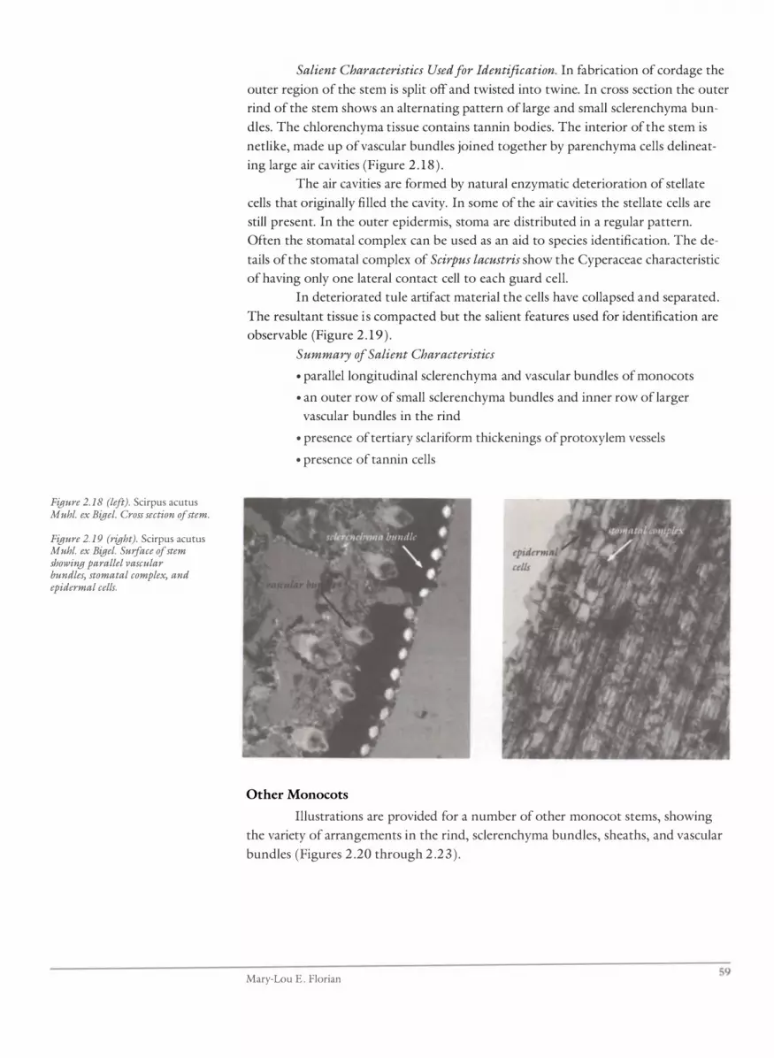
Figure 2.18 (left). Scirpus acutus Muhl. ex Bigel. Cross section of stem.
Figure 2. 19 (right). Scirpus acutus Muhl. ex Bigel. Surface of stem showing parallel vascular bundles, stomatal complex, and epidermal cells.
Salient Characteristics Used for Identification. In fabrication of cordage the
outer region of the stem is split off and twisted into twine. In cross section the outer
rind of the stem shows an alternating pattern of large and small sclerenchyma bun
dles. The chlorenchyma tissue contains tannin bodies. The interior of the stem is
netlike, made up of vascular bundles joined together by parenchyma cells delineat
ing large air cavities (Figure 2 . 1 8 ) .
The air cavities are formed by natural enzymatic deterioration of stellate
cells that originally filled the cavity. In some of the air cavities the stellate cells are
still present. In the outer epidermis, stoma are distributed in a regular pattern.
Often the stomatal complex can be used as an aid to species identification. The de
tails of the stomatal complex of Scirpus lacustris show the Cyperaceae characteristic
of having only one lateral contact cell to each guard cell.
In deteriorated tule artifact material the cells have collapsed and separated.
The resultant tissue is compacted but the salient features used for identification are
observable (Figure 2 . 19 ) .
Summary of Salient Characteristics
• parallel longitudinal sclerenchyma and vascular bundles of monocots
• an outer row of small sclerenchyma bundles and inner row of larger
vascular bundles in the rind
• presence of tertiary sclariform thickenings of proto xylem vessels
• presence of tannin cells
Other Monocots
Illustrations are provided for a number of other mono cot stems, showing
the variety of arrangements in the rind, sclerenchyma bundles, sheaths, and vascular
bundles (Figures 2 .20 through 2 .23 ) .
Mary-Lou E . Florian 59
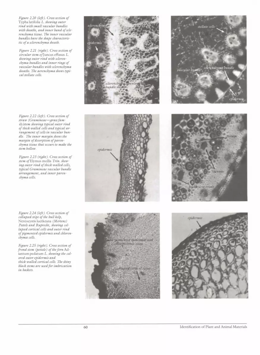
Figure 2.20 (left). Cross section of Typha latifolia L. showing outer rind with small vascular bundles with sheaths, and inner band of sclerenchyma tissue. The inner vascular bundles have the shape characteristic of a sclerenchyma sheath.
Figure 2.21 (right). Cross section of circular stem ofJ uncus effusus L. showing outer rind with sclerenchyma bundles and inner rings of vascttlar bundles with sclerenchyma sheaths. The aerenchyma shows typical stellate cells.
Figure 2.22 (left). Cross section of straw (Gramineae-grass family}stem showing typical outer rind of thick-walled cells and typical arrangement of cells in vascular bundle. The inner margin shows the ma"QJin of desorption of parenchyma tissue that occurs to make the stem hollow.
Figure 2.23 (right). Cross section of stem ofElymus mollis Trin. showing outer rind of thick-walled cells, typical Gramineae vascular bundle arrangement, and inner parenchyma cells.
Figure 2.24 (left). Cross section of collapsed stipe of the bull kelp, Nereocystis luetkeana (Mertens) Postels and Ruprecht, showing collapsed cortical cells and outer rind of pigmented epidermis and chlorenchyma cells.
Figure 2.25 (right). Cross section of frond stem (petiole) of the fern Adiantum pedatum L. showing the colored outer epidermis and thick-walled cortical cells. The shiny black stems are used for imbrication in baskets.
60 Identification of Plant and Animal Materials

Structure of Bull Kelp or Seaweed Stipe
Seaweeds are algae; they do not have true stems or roots . The plant body is called a
thallus and is made up of groups of similar cells. In some species, such as the bull
kelp, these cells take on the form of a long stemlike structure called a stipe and root
like structures called holdfasts. Along the North American Pacific coast, the distribu
tion area of the bull kelp, the stipe was a ready-made piece of cordage for
aboriginals.
Nereocystis luetkeana (Mertens) Postels and Ruprecht (Bull kelp stipe)
Description. Bull kelp is a brown marine algae . It has a very long ropelike stipe
which has a bulbous float at its upper end from which several thin leaflike blades
arise, and an interwoven mass at the other end, which acts as a holdfast on a solid
substrate at the sea bottom.
The stipe has three regions seen in cross section: the outer epidermis, the
central medulla, and, between these two, the cortex . The outer epidermis or epider
mal meristem is composed of five to ten layers of cells covered with mucilage in
which diatoms are commonly caught. The epidermis contains the chloroplasts that
impart the brown color to the tissue.
The cortical cells are thin-walled isodiametric cells which collapse dramati
cally on drying. The medulla cells are variable in size; some are small, branching fila
ments and others large trumpeted sieve tubes. The cells are loosely and randomly
organized.
Changes Due to Deterioration. During fabrication or drying, the thin-walled
cells of the cortex and medulla collapse and the stipe shrinks and becomes com
pacted. On rehydration, the collapsed cells do not regain their original shape.
Summary of Salient Characteristics. The identification of N. luetkeana stipe
material used in cordage is based on the following specific deterioration patterns
(Figure 2 .24):
• cross section of partially rehydrated cortex shows characteristic pattern of
collapsed cortical cells
• distinct structural demarcation of outer pigmented epidermis, which easily
separates as a rind on sectioning from the cortex
• epidermis has characteristic dark grey-green color; cortex/medulla com
plex is light tan
Details ofthe Structure of Ferns and Horsetails
The ferns and horsetails have underground rhizomes with true roots. Stems grow
out along the length of the rhizome. Many leaves grow out at nodes along the stem.
Often the stem of the fern and the rhizome of the horsetails are heavily pigmented.
This material is used for decoration in cultural material . The tissue arrangement in
the frond stem (petiole) of the fern Adiantum pedatum and the rhizome of the
horsetail Equisetum arvense are illustrated in Figures 2.25 and 2 .26a,b.
Mary-Lou E. Florian 61

Figure 2.26. Cross section of rhizome of the horsetail, Equisetum arvense L. (a) Outer colored epidermis and hypodermis, and inner cortical cells filled with starch grains. (b) Outer rind and one of the many vascular bundles supported by parenchyma girders in the central region of the rhizoid.
Figure 2.27. Cross section of Yucca sp. rootlet. (a) Outer cortical tissue, distinctive endoderm is, and central core of vascular tissue. (b) Fabricated into cordage. All the tissue external to the endodermis has been removed, exposing the colored endoderm is.
Structure of Yucca Rootlets
Yucca sp. Salient Characteristics Used for Identification. The yucca rootlet is a true root. It has
an outer epidermis and central core of vascular tissue separated by cortical tissue
(Figure 2 .27a) . The central core of vascular tissue is surrounded by a layer of thick
walled cells called the endodermis. These cells may contain suberin and may be
pigmented orange or brown. In fabrication of the rootlets, the outer epidermis and
cortex are removed, exposing the colored endodermis. The fabricated material is the
endodermis and central stele (Figure 2 .27b). This material is used for its strength
and color.
62 Identification of Plant and Animal Materials

Identification of Monocot Leaves
Laboratory Instructions
1 . Make wet-mount microscope slides of longitudinal and cross sections of the
following mono cot leaf materials:
• Yucca
• Carex obnupta (swamp grass)
• Typha latifolia (cattail)
• Phyllospadix scouleri ( seagrass)
• Xerophyllum tenax (squaw grass)
• Zea mays (corn)
• Hierochloe odorata (sweet grass)
• Zostera ( eel grass)
2 . Observe with transmitted and polarized light and identifY the following charac
teristics with the aid of the photomicrographs:
Surface (longitudinal section)
• epidermal cell pattern and outline-silica/cork cells
• stomatal pattern and complex
• vascular bundle arrangement
• protoxylem thickenings
• parenchymal chlorenchyma
Cross section (transverse section)
• sclerenchyma arrangement (polarized light)
• vascular bundle arrangement (metaxylem, protoxylem cells, phloem)
• lacunae, aerenchyma/stomata cavities, diaphragm, partitions
• chlorenchyma arrangement
• starch grains (iodine potassium iodide)
• silica bodies, tannin bodies
• phytoliths
• indication of fabrication (split/dyed)
3 . Compare with leaf sections whenever possible.
4 . Draw and record your observations. Label all parts. Use these illustrations to
assist in interpretation and identification.
5 . IdentifY the unknown artifact material.
Mary-Lou E. Florian 63

Figure 2.28. Cross section of leaf of cattail, Typha latifolia L. (a) Sclerenchyma bundles along JVith sheathed vascular bundles associated JVith the upper epidermis. The shape of the vascular bundle sheath is species specific. The needlelike phytoliths are free from the leaf tissue. (b) The intact bundles of phytoliths in the aerenchyma tissue.
Figure 2.29. Cross section of "vamp grass leaf, Carex obnupta L. (a) Girders JVith the vascular bundle separated by aerenchyma regiom. Discrete sclerenchyma bundles are in the dense chlorenchyma tissue next to the 10JVer epidermis. (b) Higher magnification of girders JVith the vascular bundle and the associated sclerenchyma.
Variations in the Anatomy of Monocot Leaves
Monocot leaves, because of their thin elongate structure, are logical materials for
weaving and cordage. The strength in the leaf is due to the parallel veins and their
strengthening sclerenchyma bundles, which also give strength to the material used
in weaving or cordage. The basic anatomy of the monocot leaf is presented in the I
chapter on anatomy. Variations due to species differences are seen in the following
illustrations, which are common North American species. Understanding these varia
tions will assist in interpretation of other species. A few species may present specific
conservation problems but, on the whole, the problems are common to all monocot
leaves. Anatomical variations of the monocot leaf in the species Typha latifolia,
Carex obnupta, Scirpus sp. , and Xerophyllum tenax are illustrated in Figures 2 .28
through 2 . 3 1 .
64 Identification of Plant and Animal Materials

Figure 2.30. Cross sections of the leaves of tlVO species of Scirpus maritimus (a) and S. microcarpus (b), sholVing an example of the species-specific arrangement and shape of sclerenchyma bundles and vascular bundle sheaths.
Figure 2.31. Cross section of squalV grass, Xerophyllum ten ax (Pursh) Nutt, sholVing the thick-walled cells of the epidermis and adjacent cortical cells and typical Liliaceae vascular bundle arrangement.
Phyllospadix scouteri Hooker (seagrass, ribbon grass, basket grass leaf)
Description. Phyllospadix is common along the shore of the Pacific coast of North
America and Japan. It is a sea grass found in surf regions near rocks, attached to the
bottom by rhizomes. The leaves of Phyllospadix are tough strap-like blades that
average 0 .5 m in length and I mm in width. When dry, they appear black and have a
ribbonlike twist throughout their length. The leaves are commonly used for imbrica
tion on baskets.
Salient Characteristics Used for Identification. In cross section, leaves show
a continuous epidermis of thick-walled epidermal cells, elongated inwards and con
taining chlorophyll (Figure 2 .32), above small bundles ofnonlignified fibers. The
central leaf region shows a few poorly developed vascular bundles and collapsed
aerenchyma tissue. In surface view the chlorophyll-containing epidermis has a dis
tinctive pattern of mostly triangular shapes. Like most aquatic vascular plants, the
epidermis has no stomatal complexes. The small birefringent fiber bundles parallel
the length of the leaf, a typical monocotyledon characteristic. Individual fibers are
nonlignified cellulosic secondary thickenings deposited in the primary wall.
Mary-Lou E. Florian 65

Figure 2.32 (left). Cross section of sea grass, Phyllospadix scouleri Hooker, showing outer birefringent walls of columnar pigmented epidermal cells and internal rows of small vascular bundles in the cortex.
Figure 2.33 (right). Cross section of eel grass leaf of Zostera marina var. latifolia Morong showing girders between the upper and 100ver epidermis and the rows of small vascular bundles.
Zostera marina
Description. Zostera marina is usually found in mud or in sandy bottom areas. It
has a broader leaf than Phyllospadix, averaging 5 mm wide. The leaf anatomy also
differs in having well-developed air canals separated by distinct girders and thick
walled epidermal cells, less elongated than Phyllospadix, and a surface epidermal
pattern of nearly hexagonal shapes (Figure 2 .33 ) .
Changes Due to Deterioration. The artifact material may lose birefringence
and most cellular detail except the continuous outer epidermis, with the characteris
tically elongated epidermal cells. The general shape of the cross section of the leaf is
retained; it shows typical fracturing as seen in the standard material.
Identification of Secondary Phloem Tissue
Laboratory Instructions
1 . Make wet-mount microscope slides of cross, tangential, and radial sections of: .
• Thuja plicata (western red cedar)
• Artemisia tridentata sp. (giant sagebush)
• Acer sp. (maple)
• Chamaecyparis nootkatensis (yellow cedar)
2 . Observe with transmitted and polarized light and identifY the following charac
teristics with the aid of the photomicrographs and the chapter on plant anatomy
and specified stain:
Cross section
• shape of phloem fibers
• arrangement of phloem fibers
• other phloem fibers
• growth rings
66 Identification of Plant and Animal Materials

Tangential
• size and shape of phloem rays
• markings/pitting of phloem fibers
Radial
• arrangement of phloem rays
• crystals
• sieve elements (toluidine blue)
• starch grains (iodine potassium iodide )
• resin/tannin bodies (ferric sulphate)
3 . Draw and record your observations. Label all parts. Use the following descrip
tions and illustrations to assist in interpretation and identification.
4 . IdentifY the unknown artifact material.
Introduction
The secondary phloem of some trees, both softwood and hardwood, is made up of
sheets of strong fibers. The sheets can be easily removed from the trunks of large
trees and fabricated into smaller sheets or strands and used for weaving or cordage .
The strength of this material comes from the intertwining and inherent strength of
the fibers. In the softwoods the secondary phloem that is used in cultural material is
found on the outside of the tree trunk and is mistakenly called bark. The true bark
in such species is only present in twigs up to two to four years old. The secondary
phloem of the dicot trees is located inside the true bark. In these cases the true bark
is removed and the secondary phloem sheets taken from the inside surface. The fol
lowing are descriptions and illustrations of secondary phloem of some common
North American species. The interpretation of these species will provide background
for the interpretation and identification of species worldwide.
Details of the Structure of Secondary Phloem
Thuja plicata Donn. (western red cedar bark)
Description. The tissue that is usually called bark is actually secondary phloem tissue,
which has a very different cellular organization from true bark. (See the section on
Identification of True Bark Tissue. ) The phloem on the cedar tree trunk takes the
place of true bark. The outer shredding phloem is dead tissue, but the phloem adja
cent to the wood in the trunk of the tree is the living phloem often called "the inner
bark." In the living phloem, nutrients are stored and transported to protoplasm
throughout the tree. New phloem is produced each year and shows annular growth
rings. After several years as functional tissue the phloem tissue becomes senile, and
takes on a mechanical protective bark function, becoming dead outer phloem.
Secondary phloem is a highly organized tissue with three basic types of
cells, (a) the sieve cells, in which protoplasm transport occurs, (b) the phloem paren
chyma, in which nutrients ( starch) are stored, and (c) the phloem fibers, the cells
that give the tissue its mechanical strength.
Salient Characteristics Used for Identification. The most distinctive features
of Thuja plicata phloem are the shapes and layers of the fibers (Figure 2 . 34a). In
Mary-Lou E. Florian 67

Figure 2.34. Secondary phloem of western red cedar, Thuja plicata Donn. (a) Cross section showing the rows of thick-walled phloem fibers, of two different sizes, alternating with phloem parenchyma and sieve elements. (b) Tangential surface showing phloem rays,fibers, and resin deposits in the remnant parenchyma cells.
cross section, the phloem fibers are in layers of two distinct shapes: a layer of thick
walled, almost square fibers (average 40 11) alternating with at least three layers of ra
dially flattened, thin-walled rectangular fibers (average 35 11 x IS 11) . The fibers are
birefringent and have a full range of interference colors. They have distinctive blind
pits along the radial walls, giving the walls a nodular appearance. The layers of these
phloem fibers alternate with a group of two sieve cells between which is a paren
chyma cell filled with starch. The parenchyma and sieve cells are not birefringent.
Living phloem-that is, phloem that was living when removed from the
tree-contains starch grains in the parenchyma cells and calcium oxalate crystals
deposited between the cell walls. In polarized light, the crystals are birefringent and
show a distinct pattern of deposition.
In senile phloem (dead mechanical tissue), an insoluble resinous material is
deposited in the parenchyma cells and both the starch grains and the calcium oxalate
crystals are metabolically removed (Figure 2 .34b).
In the dead phloem, the thin-walled parenchyma and sieve cells are easily
fractured, causing layer separation or exfoliation, which is essential to allow tangen
tial expansion of the growing tree trunk. Phloem that was dead when removed from
the tree shows these features.
Changes Due to Fabrication. The usual method offabrication involves soak
ing and heating. This does not alter the shape of fiber cells, but it encourages separa
tion of the tangential layers of fibers and results in loss of tissue integrity. The
calcium oxalate crystals or porous resin are not removed.
Changes Due to Deterioration. The fiber cells are very persistent and remain
as diagnostic features even in badly deteriorated material . The birefringence of the
fibers may be reduced, but there are usually regions of the fibers that show the full
range of interference colors . The blind pits on the radial walls of the phloem fibers
may be exaggerated by chemical or bacterial leaching and assist in identification.
Even in badly deteriorated material the phloem fibers remain in sheets or layers and
in cross section, even if cell collapse has occurred, the phloem fibers can be seen to
have two characteristic shapes: square and rectangular.
68 Identification of Plant and Animal Materials

Figure 2.35. Secondary phloem of yellow cedar, Chamaecyparis nootkatensis (Lamb.) Spach. (aJ Cross section showing thin-walled phloem fibers alternating with parenchyma and sieve cells. Birefringent calcium oxalate crystals are associated with the tissue, indicating that the tissue was metabolically active when harvested. (b J Tangential surface sholving characteristic pattern of deposition of calcium oxalate crystals which identify the tisme as secondary phloem. A few uniseriate phloem rays can be seen in thin sheet of phloem fibers. (cJ Tangential surface of secondary phloem and associated large fiber sclereid.
Summary of Salient Characteristics
• phloem fibers of two cell shapes (rectangular and square) in cross section
• continuous rows of birefringent phloem fibers alternating with three non
birefringent cells (two sieve cells and one parenchyma cell)
• porous appearing resin inclusions in parenchyma cells in "dead" tissue or
starch grains in parenchyma tissue and the presence of calcium oxalate
crystals in "living" tissue
• nodular appearance of radial wall of phloem fibers due to large blind pits
Chamaecyparis nootkatensis (Lamb.) Spach. (yellow cedar bark)
Description. The secondary phloem contains phloem fibers, sieve cells, parenchyma
cells, starch grains, and calcium oxalate crystals (Figure 2 .35a,b) in "living" tissue,
all of which are similar to Thuja plicata in physiological activity and function.
The majority of the phloem fibers are of one morphological form, radially
flattened, thin-walled, and on the average 35 ).l. by 1 0 ).l. in size. These fibers are bire
fringent and show only a white interference color. The fibers do not show distinc
tive pitting on the radial walls. In addition to these common phloem fibers, large
sclereid-like phloem fibers occur sporadically in the layers of phloem fibers and only
rarely form a continuous layer (Figure 2 .35c) .
In cross section these sclereids average 30 ).l. (tangential) by 50 ).l. (radial) .
They are birefringent and show a brilliant full range of interference colors. They
commonly show angular markings associated with pits (these large sclereids or
phloem fibers are not mentioned in the literature reviewed).
Changes Due to Fabrication. Yellow cedar secondary phloem is soaked and
extensively beaten during fabrication, which causes disorganization of the tissue and
separation into individual cells. Rarely do the layers of phloem fibers remain intact.
The fabricated material is fibrous, soft, and light tan in color.
In some cases, crystals of calcium oxalate are present and take on a specific
pattern of distribution that reflects their concentrated deposition between cell walls
near regions of sieve plates and pits of phloem. The large sclereids are randomly ori
ented in the disorganized fabricated tissue .
Mary-Lou E. Florian 69

Figure 2.36 (left). Tangential surface of secondary phloem of maple, Acer sp. (a) Typical pattern of phloem rays in the thin sheet of phloem fibers. As compared to the next microphotograph, the small size of the phloem rays suggests inner or metabolically active phloem. (b) Typical pattern of phloem rays in the thin sheet of phloem fibers. As compared to (a) the large size of the phloem rays suggests outer senile dead phloem.
Figure 2.37 (right). Tangential surface of secondary phloem of big sagebrush, Artemisia tridentata Nutt., showing typical pattern of phloem rays in the thin sheet of phloem fibers.
Figure 2.38. (a) Cross section of cherry, Prunus emarginata (Dougl.) Walpers, showing grolVth rings of collapsed phdlem cells. (b) Tangential Sltrface of bark showing shape of phdlem cells.
Changes Due to Deterioration. In badly deteriorated tissue, the small
phloem fibers may have lost all their birefringence, and it is difficult to determine
cell size or shape. The large sclereids retain their normal birefringence and full range
of interference colors.
70
Summary of Salient Characteristics
• tissue easily separates into individual cells
• friable, light tan color
• main phloem fiber (undeteriorated) has positive birefringence of white
interference color; average cell size is 35 J..l (tangential) by 10 J..l (radial ) ;
• deteriorated phloem fibers may have negative birefringence
• calcium oxalate crystals may be present and show the typical phloem depo
sition pattern
• the rare large phloem fibers (sclereids) are randomly distributed; average
size in cross section is 30 J..l (tangential) by 50 J..l (radial) ; birefringent, with
a full range of brilliant interference colors
Identification of Plant and Animal Materials

Identification of True Bark Tissue
Laboratory Instructions
1 . Prepare wet-mount microscope slides of cross, tangential, and radial sections of:
• Prunus emarginata (bitter cherry) bark
• Betula (birch) bark
2 . Observe with transmitted and polarized light and identifY the following charac-
teristics with the aid of the photomicrographs and the chapter on plant anatomy:
• shape of phellem cells
• compaction of phellem cells
• early and late phellem cell size variation
• staining reaction with: toluidine blue, sudan III, and ferric sulfate
3 . Record your observations and the details of the staining reactions. Use the de
tailed descriptions and illustrations to assist in interpretation and identification.
4. IdentifY the unknown artifact material.
Introduction
True bark is the smooth shiny outer surface of cherry tree trunks, the white sheets of
the birch tree, and the corky chunks of the cork oak. Although different in appear
ance, all composed of one type of cell, which is waterproofed with the waxy material
suberin. Suberin is the main component of cork cells. Cherry bark is used for decora
tion, but lacks structural strength due to the brittle nature of the compacted cells
and the lenticel areas of weakness. Large sheets of birch bark are used in making con
tainers; they, too, lack structural strength and usually require additional support.
Structure of True Bark
Prunus emarginata (Dougl.) Walpers (bitter cherry)
Description. Cherry bark is a true outer bark. The tissue is composed of annual layers
of cork (phellem) cells. The walls of the phellem cells are made up mainly of sube
rin, an unsaturated fatty acid that makes the cell wall impermeable to water and
gives the cells a yellow-red color. The phellem cells are oriented with their long axis
around the circumference of the tree (the opposite of wood) ; thus, in tangential sec
tions, the bark appears as a dense tissue of long narrow cells. In radial section, the
annual rings of the bark tissue are apparent and the phellem cells are seen as if in
cross section. In artifact material, the cells have collapsed and the tissue is compac
ted. Cross section shows dense long phellem cells in annual rings (Figure 2 .38a,b) .
In radial and cross section, the cells are usually not apparent, but the pattern of the
annual ring is obvious by deterioration.
Salient Characteristics for Identification. Cherry bark, even when badly de
graded, has a distinctive golden to red color. Birch bark can be distinguished from
cherry by the distinct variation of cell size and the concentration of pigmentation in
the late phellem cells of each annual ring. Filaments of saprophytic fungi or lichen
are commonly associated with the tissue and are an aid to identification of bark.
Mary-Lou E. Florian 71

Identification of Wood Tissue
Laboratory Instructions
1 . Prepare wet-mount microscope slides of cross, tangential, and radial sections of
these softwood and hardwood materials:
Hardwood
• Quercus alba (white oak)
• Tilia americana ( lime, linden, basswood)
. Acer sp . (maple)
• Ulmus americana ( elm)
• Carya sp . (nut)
Softwood
• Thuja plicata (western red cedar)
• Pinus sp . (pine)
• Picea sp . (spruce)
2 . Observe with transmitted and polarized light and identify the following charac
teristics with the aid of the photomicrographs:
72
Cross Section
Hardwood
• vessel arrangement/porosity/ring or diffuse
• pattern/parenchyma or fibers
• arrangement of parenchyma (at growth rings/around vessels)
Softwood
• resin canals
• growth rings
• parenchyma
Tangential
• wood rays
• crystals
Radial
Hardwood
• vessel pitting
• perforation plates
• spiral thickenings in fibers or vessels
Softwood
• cross-field pitting
• border pits
• ray tracheids
• end wall of ray parenchyma
• spiral thickenings in tracheids
Identification of Plant and Animal Materials

3 . Proceed to wood species identification using the key to wood identification
supplied for y�ur specific species. Draw and record your observations. Use the
detailed descriptions and illustrations to assist in interpretation and identifica
tion; note the following:
• resin canals
• end wall of ray parenchyma
• ray tracheids
• cross-field pitting
• spirals
• others
4. IdentifY the unknown artifact material.
Introduction
Wood is the internal supporting structure of trees. It is a specific tissue called xylem,
which is made up of a group of cells that function for transport of water and for me
chanical strength. The anatomy of the wood varies with species, allowing species
identification. The different arrangement and amounts of the cells gives the different
structural qualities to the different woods. The variation in the strength characteris
tics of balsa wood and oak are a result of these different cell arrangements as well as
cell structure . But both can easily be identified as wood because of common cell
types present and basic organization. The use of split elm is logical because of ana
tomical features allowing easy splitting. The use of alder or maple for carving is also
possible because of the specific wood anatomy.
Wood identification is a discipline in itself. The information presented here
illustrates the complexity of wood, the variety of cells present, and the inherent
weaknesses of some cells, which may cause conservation problems in artifacts .
Details of the Anatomy of Softwoods
Thuja plicata Don Donn. ex D. Don (western red cedar)
Description. The wood of the branch, root, and trunk has the same anatomical char
acteristics; thus identification is keyed to species origin of coniferous wood.
Changes Due to Fabrication. In fabrication, cedar withes were heated prior
to mechanical removal of th� bark, then beaten, steamed, worked until soft and pli
able, and finally twisted together. The mechanical and physical damage due to fabri
cation does not interfere with identification of the wood species. Even in badly split
branch fragments, true cross, tangential, and radial sections can be made easily, and
the salient characteristics used for identification can be observed readily using a
water-mount slide preparation.
Changes Due to Deterioration. Withes, consisting mainly of sapwood, are
prone to chemical or biological deterioration. As a result, the shape of the taxodioid
cross-field pits is often altered, but the pattern of deterioration usually reflects the
original shapes. Sometimes the pits are not readily apparent, but staining with safra
nin or toluidine blue does assist in this situation.
Mary-Lou E. Florian 73

Branches often contain compression wood, which is formed by anomalous
growth to compensate for branch weight or wind force in order to maintain the nor
mal tree form in relationship to gravity and light. A similar reaction occurs in hard
woods. Compression wood is identified by a spiral pattern of cellulose deposition in
the secondary wall in the wood tracheids. These may be easily mistaken for spiral
thickening in the tertiary wall, a normal anatomical characteristic of some wood spe
cies (Douglas fir, yew), which is used in wood identification.
Sapwood is prone to soft rot in which the fungi filaments selectively lyse
the cellulose from the secondary cell wall leaving spiral lytic troughs. These spirals
reflect the natural spiral orientation of cellulose fibrils in the cell wall. These spirals
also could be mistaken for spiral secondary or tertiary wall thickening, but under
polarized light, the spiral lytic troughs show loss of birefringence due to the loss
of cellulose, whereas spirals in compression wood and tertiary thickenings show
increased birefringence due to the increase of cellulose .
Summary of Salient Characteristics
• end walls of ray parenchyma cells are smooth and indentured
• height of wood rays 1 to 12 cells
• taxodioid pits in cross fields (Figure 2 .39)
• absence of resin canals
• absence of ray tracheids
Picea sitchensis (Bong. ) Carr. (Sitka spruce root)
Description. The root wood has the same basic anatomical characteristics as the
trunk wood; thus identification keys (Panshin and de Zeeuw 1970, Friedman 1978)
based on wood anatomy can be used (Figure 2 .40a,b) .
Changes Due to Fabrication. Bundles of long spruce roots were scorched
over a hot fire, enough to heat the wood of the root but not to burn through the
bark. Next, each root was pulled through a split stick to remove the bark, then split
in half. The halves were pulled over a flat object until they were completely flexible,
then dried. Flattening may be due to collapse on drying or mechanical pressure caus
ing cell collapse . Spruce root cordage has a midline on the inner cut surface due to
the presence of large coalescent resin canals in the central region that collapse on
drying, forming a depression.
The mechanical and physical damage caused by fabrication should not inter-
fere with wood species identification.
Summary of Salient Characteristics
• presence of resin canals with surrounding thick-walled epithelial cells
• presence of ray tracheids
• presence of piceoid pits in cross fields
• nodular end walls of ray parenchyma cells
74 Identification of Plant and Animal Materials

Figure 2.39. Tangential section of wood of western red cedar, Thuja plicata Donn., showing taxodioid pits in the crossfields of the ray parenchyma. The ray parenchyma walls are smooth and ray tracheids are not present.
Figure 2.40. Tangential section of wood of Sitka spruce, Picea sitchensis, (a) Piceoid pits in the crossfields of ray parenchyma. The ray parenchyma cells are nodular and ray tracheids with half-bordered pits are on the outside of the ray parenchyma. (b) Two resin canals, with thick-walled epithelial cells, in the wood rays.
Identification of Wood Origin (Branch, Root, or Trunk)
Laboratory Instructions
1 . Make wet-mount microscope slides of cross sections of root, branch, and trunk
wood of the following softwoods:
• Thuja plicata (western red cedar)
• Picea sitchensis (Sitka spruce)
• Pinus sp. (pine)
2 . Observe with transmitted and polarized light and identity the following charac
teristics with the aid of the photomicrographs and the chapter on plant anat
omy. Compare and draw to show differences in:
• density and width of growth rings
• tracheid cell size and shape and cell wall thickness
Mary-Lou E. Florian 75

Figure 2.41 (left). Cross section of a root of western red cedar, Thuja plicata Donn., showing loose open tracheids and circular grOlvth rings with a few thick-walled late-wood cells.
Figure 2.42 (right). Cross section of a twig of western red cedar, Thuja plicata Donn., showing dense thickwalled tracheids and circular growth rings with many thickwalled cells.
• presence of parenchyma (longitudinal)
• measured width of ray parenchyma cells
• overall shape and section (indication of fabrication)
• resin canals (if present)
3. Make tangential and radial sections of root or branch wood for species identifi
cation. Proceed as for wood identification.
4. IdentifY the unknown artifact materials using the following illustrations to assist
in interpretation.
Details of the Variation in Wood from Branch, Root, and Trunk
The wood of branch, root, and trunk can be easily distinguished. The main differ
ences are the density and size of the cell and their circular or linear arrangement.
The wood from trunks or large branches shows the linear, orderly arrangement of
the tissue with a gradation from a few layers of smaller thick-walled late wood tra
cheids to mainly larger thin-walled early wood tracheids.
In the branch (withe), the tracheids are all thick-walled and have an overall
orderly and very compact arrangement that-unless it is over several centimeters in
diameter-will show circular growth rings.
The root is similar to branch wood in having a circular arrangement of cells,
but in the root the cells are larger, have relatively thin walls, are often collapsed, and
the overall tissue has an open and disorganized appearance. Resin canals (when pres
ent) may be confluent or join together in a row. Often there may be more than the
normal (for trunk wood) number of rows of bordered pits in the wood tracheids.
The longitudinal parenchyma in roots are very prominent and the width of the ray
parenchyma cells is significantly greater than in the wood of trunk or branch. Struc
tural differences among branch, root, and trunk wood are illustrated in Figures 2.41
to 2 .47, showing cross, radial, and tangential sections of ThuJa plicata.
76 Identification of Plant and Animal Materials

Figure 2.43 (left). Cross section of heartwood of western red cedar, Thuja plicata Donn., showing tracheids and linear growth rings with thick-walled late wood cells.
Figure 2.44 (right). Radial section of root of western red cedar, Thuja plicata Donn., showing ray parenchyma cells of the wood ray and tracheids with bordered pits on the radial walls. The wide ray parenchyma cells-as compared to those in the trunk-are characteristic of root tissue.
Figure 2.45 (left). Radial section of trunk wood of western red cedar, Thuja plicata Donn., showing narrow ray parenchyma cells of the wood ray and tracheids with bordered pits on the radial walls.
Figure 2.46 (right). Tangential section of root of western red cedar, Thuja plicata Donn., showing ray parenchyma cells of the wood ray and tracheids with bordered pits on the radial walls. The wide ray parenchyma cells are characteristic of root tissue.
Figure 2.47. Tangential section of trunk wood of western red cedar, Thuja plicata Donn., showing narrow ray parenchyma cells of the wood rays and tracheids with bordered pits on the radial walls.
Mary-Lou E. Florian 77

Cited References
Bally, W.
1953 Hard fibers (Agava, abaca, and New Zealand flax). CIBA Review 99:3542-3564.
Collings, T. and D. Milner
1982 The identification of non-wood papermaking fibers: Part 3 . The Paper Conservator
7:24-27.
Coville, F.V.
1902 Plants used in basketry. In Aboriginal American basketry. O.T. Mason, ed.
U.S. National Museum Report No. 484.
Friedman, J.
1 959 Wood identification by microscopic examination. A guide for the archaeologist on the
Northwest Coast of North America. Heritage Record No. 5 . Victoria, BC: British
Columbia Provincial Museum.
Hall, W.J. (ed.)
1951 Identification of textile materials. Manchester: The Textile Institute.
Harris, M. (ed.)
1954 Handbook of textile fibers. Washington, D.C. : Harris Research Lab, Inc.
1937
1970
Nutman, F.J.
Agava fibers, part I: Morphology, histology, length, grading problems. Empire
Journal of Experimental Agriculture 5 :75- 1 1 .
Panshin, A.J., and C. de Zeeuw
Textbook of wood technology. 3rd ed. New York: McGraw-Hill.
Schaffer, E.
1981 Fiber identification in ethnological textile artifacts. Studies in Conservation
26(3) :571 -585 .
Turner, N.J.
1979 Plants in British Columbia Indian Technology. British Columbia Provincial Museum
Handbook 38 .
78 Identification of Plant and Animal Materials
Additional Reading
Monocotyledon Anatomy
Brown, W.V.
1959 Leaf anatomy in grass systematics. Botanical Gazette 1 19 : 1 70-178 .
Cutler, D.F.
1969 Anatomy of monocotyledons. In Juncales, Vol. IV. Oxford: Clarendon Press .
1954-55
Greiss, E.A.M. and K. Naguib
An anatomical study of some sedges in relation to plant remains of ancient Egypt.
Bulletin de nnstitut d)Egypte 37:235-271 .
Kau!, R.B.
1971 Diaphragms and aerenchyma in Scirpus validus. American Journal of Botany
58 :808-8 16 .
Korsno, E .
1954 Anatomy of weeds. Oslo, Norway: Grondahl & Sons.
Metcalfe, C.R.
1960 Anatomy of the monocotyledons. In Gramineae, Vol. I. Oxford: Clarendon Press.
1963 Comparative anatomy as a modern botanical discipline (with special references to
recent advances in the systematic anatomy of monocotyledons) . In Advances in
Botanical Research, Vol. I. R.O. Preston, ed. New York: Academic Press.
1971 Anatomy of the monocotyledons. In Cyperaceae, Vol. V. Oxford: Clarendon Press.
Monoyer, A.
1933 Contribution a l'anatomie du genre Scirpus. Memoires de la Societe royale des sciences
de Leige) Series 3, 1 8 : 1-184.
Ogden, E.C.
1974 Anatomicil patterns of some aquatic vascular plants of New York. Bulletin #424.
Albany, NY: N.Y. State Museum and Science Service.
Parry, D.W. and F. Smithson
1964 Types of opaline silica depositions in the leaves of British grasses. Annals of Botany
28( 109 ) : 169-185 .
Plowman, A.B.
1906 The comparative anatomy and phylogeny of the Cyperaceae. Annals of Botany 20
( 127): 1-35 .
Mary-Lou E. Florian 79

Tomlinson, P.B.I.
1969 Anatomy of the monocotyledons. II: Palmae, III: Commelinales-Zingiberales.
Oxford: Clarendon Press .
Pteridophytes
DeBary, A.
1938 Comparative anatomy of the vegetative organs of the phanerogams and ferns. F.O.
Bowe and D.H. Scott, trans. Oxford: Clarendon Press.
Ogura, Y.
1972 Comparative anatomy of vegetative organs of the Pteridophytes. In Encyclopedia of
plant anatomy, Vol. VII . Berlin: Gebruder Borntraeger.
Parihar, N.S.
1965 An introduction to em bryophyta. In Pteridophytes, Vol. II . Allahabad, India: Indian
University Press.
Potamogetonaceae (Pond Weed, Seagrass)
Chrysler, M.A.
1907 The structure and relationships of the Potamogetonaceae and allied families.
Botanical Gazette 44( 3 ) : 161-18 8 .
Laminariales (Seaweed, Bull Kelp)
Smith, A.I.
1939 The comparative histology of some of the Laminariales. American Journal of Botany
26:571-585 .
Roots and Branches
Fegel, A.C.
1941 Comparative anatomy and varying physical properties of trunk, branch and root
wood in certain Northeastern trees. In Bulletin of the New York State College of
Forestry Technology. Publication No. 55 . Syracuse, NY: Syracuse University Press.
Lebedenko, L.A.
1 962 Comparative anatomical analysis of mature wood of roots and stems of some woody
plants. Translation RTS 2 194. Yorkshire : National Lending Library of Science and
Technology, Boston Spa.
Patel, R.N.
1971 Anatomy of stem and root wood of Pinus radiata D.Don. New Zealand Journal
for Science 1 ( 1 ) :37-49.
80 Identification of Plant and Animal Materials

Secondary Phloem (Inner Bark) and True Bark
Abbe, L.B. and A.S. Crafts
1934 Phloem of white pine and other coniferous species. Botanical Gazette 1 00:695-722.
1954a
1954b
Chang, Y.P.
Anatomy of common North American pulpwood barks. Technical Assn. of the
Pulp and Paper Industry Monograph Series ( 14) . New York, NY . Bark structure of North American conifers. Technical Bulletin No. 1 095 .
Washington, DC: U.S . Department of Agriculture.
Den Outer, R. W.
1967 Histological investigation of secondary phloem of Gymnosperms. Mededelingen
Landbouwhogeschool Wageningen. Wageningen, Netherlands: H. Veenman
& Zonen NV.
Diettert, R.A.
1938 The morphology of Artemisia tridentata Nutt. Lloydia 1 ( 1-4) :4-74.
Esau, K.
1969 The phloem. In Encyclopedia of plant anatomy, Vol.V. Berlin: Gebruder
Borntraeger.
Isenberg, I.H.
1943 The anatomy of redwood bark. Madrona 7(3 ) :85-90 .
Jensen, W.
1949 The connection between the anatomical structure and chemical composition and
the properties of outer bark of white birch. The Finnish Paper and Timber Journal
3 1 (7) : 1 1 3-1 16 .
MacDaniels, L.H.
1918 The histology of the phloem in certain woody Angiosperms. Journal of Botany
5 : 347-378.
Martin, R.E. and J.B. Christ
1970 Elements of bark structure and terminology. Wood and Fiber 2(3) :269-79.
Srivastava, L.M.
1964 Anatomy, chemistry, and physiology of bark. International Review of Forestry
Research 1 :203-77.
Mary·Lou E. Florian 8 1

Wood Anatomy
Dale, A.
1968 Comparative wood anatomy of some shrubs native to the Northern Rocky Mountains.
Research paper INT. 45. Ogden, Utah: U.S. Department of Agriculture Forest
Service. Intermountain Forest and Range Experiment Station.
Kribbs, D.A.
1 968 Commercial foreign woods on the American market. New York: Dover Publications .
Kukachka, F.
1960 Identification of coniferous woods. Technical Association of the Pulp and Paper
Industry43( 1 1 ) :837-46.
82 Identification of Plant and Animal Materials

3 Technology of Plant Materials U sed in Artifacts Ruth E. Norton
T.7" nowing the composition and properties of materials that are used in artifacts,
..l.'-.how these materials are processed, and the manner in which they are manipu
lated and combined in constructing and decorating artifacts is essential to under
standing the present condition of an artifact as well as predicting how it will respond
to its environment and to conservation treatment. It is equally important to be famil
iar with the cultural context and use of an artifact in order to be aware of both the al
terations that may have taken place through its use and also the intangible
properties with which it may have been invested.
A great deal of anthropological literature is available on the processing,
construction, decoration, and use of artifacts, based on first-hand observation,
informants, and actual examination of artifacts. This invaluable source of informa
tion forms the basis of much of our understanding of the artifacts. Until recently,
though, there has been very little detailed analysis of the artifacts themselves to find
what they can tell us. Canada has led the way through programs like the Native Ma
terials Project of the Canadian Conservation Institute and Florian's work on the ex
amination of materials used in Native American artifacts for identification and
evidence of alteration through processing. Work in other cultural areas has been
prompted by the need to identifY specific conservation problems: for example, the
examination of fatty residue on African wood figures (Pearlstein 1 986) and the
research on Phormium species in New Zealand (Christensen 1985) .
There i s a need to continue this type of examination to gain direct evidence
of materials identification, processing, and use. In turn, this is necessary to gain
information on artifacts not covered in detail by the anthropological literature, to
confirm or question the literature, and to be able to identifY the extent of processing
and use of specific artifacts. For example, retting and extraction of monocot fibers re
moves pithy parenchymous tissue. Therefore, microscopic examination of fibers for
the presence and quantity of parenchymous tissue may yield information on the ex
tent of processing in the production of particular pieces of cordage. Comparison of
the presence of oils and grime, of salt and food residue, and of amorphous plant tis
sue in unused and used cordage may yield information on how and how much it
was used. While it is important to know the literature, it is wise to see what the arti
fact itself has to say.
Ruth E. Norton 83

It is particularly important to initiate artifact analysis, because conservation
treatments may alter, remove, or camouflage that evidence. In this respect, the appli
cation of conservation treatment should be considered in the light of whether it is
absolutely necessary despite the potential alteration of evidence, or whether no treat
ment or a purely mechanical treatment would suffice .
Alterations to plant materials are incurred during processing and artifact
construction. The effects of these alterations should be considered both from the
point of view of the artifact manufacturer-how the process achieves the desired
working, functional, and visual properties-and from the point of view of the people
now responsible for the preservation of the artifact-how the process may ultimately
affect the structural, chemical, and mechanical characteristics and stability of the ma
terial . This chapter should be studied while bearing in mind the structure and com
position of plant materials detailed in Chapters 1 and 2, and the processes of
deterioration discussed in Chapter 4.
Because the composition and structure of different parts of plants are gener
ally distinct and determine both how parts are processed and what artifact types they
are used for, it is important to look not only at general processing, construction, and
decoration techniques, but also at their application to particular plant organs and tis
sues. Since the procedures for processing and constructing materials differ region
ally, examples are used to illustrate procedures where generalizations would be
meaningless or misleading. (The emphasis on Pacific and southeast Asian material re
flects the experience of this author. )
As so many plants are utilized, i t is not possible to mention-let alone dis
cuss-them all. Therefore, the processing and manufacture of some materials and
artifacts that have already received much attention in the literature, like beaten inner
barkcloth, are only superficially considered, while other materials and artifacts are
looked at in a bit more detail. (Hardwood, softwood and plant extractives, such as
resin, latex, and wax, have not been included because of time restrictions in the prep
aration of these notes. )
General Processing Procedures
It is difficult to speak generally about the processing of plant materials and their ma
nipulation to construct artifacts, because processing and construction often take
place concurrently. Some plant organs also require considerably more processing
than others. However, it is useful to look at some of the basic processes in light of
their purpose and effect on the materials.
Cultivation and Harvesting
Cultivation may affect the strength, fiber length, and composition of plant tissue.
Some materials, like gourds and bamboo, are purposefully modified in shape dur
ing growth.
In some cases the harvesting or collection of the raw material is determined
by the environment. In tropical areas, collection may be limited in the wet season
when access to the plants and drying are difficult. Some materials are most easily
84 Technology

harvested at particular times of the year. For example, bark is most easily stripped
from a tree when the sap is running and the vascular cambium is moist and active.
On the other hand, for some materials that exhibit continual year-round growth,
harvesting may be done as the need for a particular artifact arises.
Harvesting may also be determined by the maturity of the plant or plant
part. Gourds are harvested when fully mature so that the shell will dry hard and du
rable; immature bamboo splits and collapses severely upon drying, making it unsuit
able for many uses. Other plant parts are harvested when immature . Leaf strands for
baskets and textiles are collected from the immature leaf shoots of the Livistonia and
nipa palms, as the strands are then easily stripped from the leaves and are soft and
flexible.
The composition, working properties, and durability of the plant material
are affected by the harvest time and the maturity of the plant. Drying during wet sea
sons can result in mold and fungal degradation and staining. The season may
affect starch and sugar concentrations in the material. Maturation often involves de
position of lignin, extractives, suberin, and cutin, and thickening of cell walls.
Drying
Drying plant materials consists of reducing their moisture content in the green state
to that at equilibrium with the ambient relative humidity. The effect oflowering the
moisture content below the fiber saturation point on the cell wall and on the mate
rial as a whole, in terms of shrinkage, cell collapse, and precipitation of starch, sugar,
and plant extractives is covered in the literature and in other chapters of this book.
The manufacturer of an artifact must consider how drying is likely to affect
the flexibility and density of the material. Rate of drying and position during drying
influence cracking, shrinkage, and distortion. Because many plant materials are
stored between processing stages, thorough drying is necessary to help prevent
growth of mold and mildew.
Retting and Cooking
Retting (soaking the plant material in water) and cooking (soaking in heated water
or alkaline solutions) degrades and/or extracts components of the material. The pro
cess involves the extraction of material by solution and leaching, and the degrada
tion of material assisted by bacterial and fungal action. Soaking may be done in
running fresh and salt water, stagnant fresh and salt water, and mud. A side effect
may be the deposition of metallic and mineral salts from the water and mud into the
plant material. Cooking in water or alkaline (usually wood ash) baths augments the
degradation of material and increases the amount and type of material extracted
for example, waxes, oils, and pectin may also be extracted.
Retting and cooking are done for a variety of reasons. The degradation and
extraction of components may increase pliability and suppleness, and aid the extrac
tion and separation of fibers. Materials may be made more durable; for example, the
removal of starch from green bamboo is thought to make it less attractive to wood
borers. Retting aids the removal of unwanted soft tissue and components, as, for
Ruth E. Norton 85

example, in the processing of gourds where the inner pulp and bitter extractives are
removed. Brief cooking in water lightens the color of some leaves.
Fiber Extraction
Fiber extraction from monocot stems, leaves, and fruits !S the process of separating
the unwanted substances and epidermal and parenchymal tissue from the fiber and
fibrovascular bundles-referred to collectively as fibers. Extraction is usually done
mechanically by stripping, scraping, or shredding. This is sometimes preceded or
followed by retting or cooking and usually followed by washing and drying in the
sun. Some fibers, such as coconut husk fibers and some agave fibers, are extracted
by retting and beating to remove unwanted tissue. The harshness of the mechanical
stripping and the presence and amount of retting and cooking affect the extracted
fiber. The fiber bundles generally remain intact, but the more strenuous the extrac
tion, the cleaner the fiber-that is, the fiber will contain less extractives, and less
parenchymal and vascular tissue will adhere to the fibers. Very mechanically and
chemically harsh treatment may cause fraying, fracturing, and weakening of the
fiber. Plant fibers differ in the degree of treatment they can withstand without
significant weakening.
Inner bark fiber extraction after harvesting involves removing the outer
bark. This is usually preceded or followed by retting and/or cooking to remove
plant sap, pectin, and gums, making the inner bark more supple, whiter, and cleaner
when dried, and aiding the separation of individual fibers. Sometimes, as in the pro
cessing of Touchardia latifolia, no retting or cooking is involved; the outer bark and
sap are removed by scraping.
Wetting and Heating
Wetting and heating may be done immediately prior to or during manipulation to
attain or maintain the suppleness of the plant material. Inner bark fibers are wetted
during beating in the production of barkcloth; leaf strands are wetted to keep them
pliable during weaving. Given the extended periods of wetting to which many plant
materials and artifacts are subjected during processing and use, this brief wetting
probably has comparatively little long-term effect on the material, except perhaps
the unintentional introduction of any metallic or mineral salts present in the water.
Bark sheets are steamed before bending by placing the green bark over a
fire . Changes in the cellular structure and components may result from the internal
steam and pressure created; often, charring of exterior material occurs.
Bleaching
Leaves, fibers, and stems are often laid in the sun for several days to lighten the
color. The time of exposure is fairly short, so there may be little degradation of
material. (The artifact, furthermore, may spend much of the rest of its useful life
in the sun . )
86 Technology

Dyeing
Dyeing with natural dyes extracted from flowers, fruits, wood, and bark, using wood
ash and metallic salts as mordants and color modifiers, and dyeing with all classes
of synthetic dyes are practiced on most plant materials . The dyeing process itself
may involve cooking in acidic and alkaline solutions. The residual acids, alkalis, and
metallic salts are known to affect plant material to varying degrees. Dye-related
damage of textile fibers and artifact materials with natural and synthetic dyes is well
documented in conservation and industrial literature . Much of the brittleness,
fragmentation, and loss of tensile strength that may occur appears to be related to
metallic catalysis of oxidation breakage of the cellulose molecule .
General Construction Techniques
Construction involves the manipulation of materials to build or create a form.
This manipulation may consist of removing, reshaping, joining, and interworking
materials.
Familiarity with construction methods is important to accurately document
artifact construction and to understand the mechanical strengths and weaknesses of
artifacts. The latter is essential in determining causes of deterioration, safe mounts
and supports in storage and display, and appropriate repair and restoration proce
dures. For example, examining the corner joints of a painted wood box may lead to
an understanding of the cracking and cupping that has occurred to the paint layer in
those areas. Some interworked fiber constructions are strong along the horizontal
axis while others are weak in that direction and require different support systems.
Accurate repositioning of loose threads in the damaged area of a woven bag requires
a detailed understanding of the original weave.
Evidence of the type and shape of tools used to remove material may be
noticeable on the artifact in the form of characteristic tool marks. Microscopic
particles of cutting and abrasive substances may still remain on an artifact's surface.
Artifacts that are themselves cutting, incising, drilling, and abrasive tools may also
retain particles or fragments of materials that are important in understanding their
cultural use.
Removal of Material
Material can be removed using various tools, each of which may remove different
quantities and leave different marks on the material.
Cutting
The removal of material takes place using flat or shaped blades or a series of fine
blades to carve, chisel, engrave, saw, rasp, or scrape . If not removed by further sand
ing, polishing, or finishing, characteristic tool marks can be seen on the surface: flat
or slightly concave facets from knife, adze, or chisel; curved or flat faces depending
on the shape of the chisel; rough, nearly parallel or concentric lines of saw teeth as
the saw passes through the material. Rasps generally remove material by cutting, but
Ruth E. Norton 87

a
---�[.]t----b
__ ____ �t(� ______ _
Figure 3.1. (a) A strip drilled by pressure and abrasion from one side. (b) A strip drilled by the same method but from both sides.
fibrous material is often left somewhat rough and furry as a rasp both cuts and in
cises. In removing large quantities of material, cutting may be preceded by burning.
in some dugout canoe constructions, for example, the wood of the interior may be
charred, then the charred wood removed with an adze.
Incising
Incising involves using a sharp point to push away material, such as a pointed knife,
awl, or stylus to incise writing or decoration on palm leaf manuscripts, bamboo
containers, and gourds. Incised lines are generally fine and have rough edges.
Drilling
Drilling removes material using a rotating bit with a cutting edge or surface. Drills
with cutting edges slice away the material. Drills with cutting surfaces use abrasion
under pressure to remove the material. These may be dull metal bits that abrade
rather than slice; rough bits like coral that have abrasive surfaces; or hard, smooth
bits that push and move an abrasive powder, made of added grit or grit removed
from the material, which does the actual abrading.
Drilling tools are usually pointed, and the shape of the drilled hole reflects
the profile of the point. Holes drilled completely through a material may be drilled
from one or both sides. For example, a dense strip of material drilled by pressure
and abrasion from one side will be of the same diameter throughout, although the
cut fibers may be pushed slightly in the downward direction and the underside
fibers may be frayed or splintered. The same strip drilled by pressure and abrasion
from both sides will have two clean surfaces, and the hole may be hourglass-shaped,
reflecting the shape of the drill point (Figure 3 . 1 ) .
Sanding
Fine bits of material are removed by rubbing with an abrasive . Generally, sanding is
characterized by coarse to extremely fine parallel or concentric grooves whose size
and configuration depend on the rubbing motion, the pressure applied, and the size
and shape of the abrasive.
Reshaping
Reshaping involves moving a solid material into a new shape by molding or model
ing rather than removing material to create a new shape.
Molding
Molding material like wood and bark involves first heating, steaming, or boiling to
make the material pliable enough to be bent without breaking. The material must
be held or secured in its new position until cool and dry. This is only a semiperma
nent reshaping, as the material often has a tendency to return somewhat to its origi
nal shape. It is usually necessary to secure or restrain the material to maintain the
new shape.
88 Technology

Modeling
Modeling consists of forming or building up a shape with a plastic material . To
move a solid material into a new shape, the material must be plastic (malleable)
enough to move without fracture or must be made more plastic by the application
of heat. Thermoplastic plant exudates, like resins and some waxes, are warmed with
the hands or fire, and pushed or built up to make figures and fill areas. Papier
mache, strictly speaking, is not modeling because it involves the use of adhesives to
laminate layers of paper, but it is modeling in the sense that the form is built up
from material that is malleable in its wet state.
Joining
Parts may be joined during construction in three general ways. Usually, combina
tions of these techniques are used.
Worked Joins
Parts are cut so that they physically interlock. Examples of worked joins include
dovetail, scarf, lap, and tongue-and-groove joins. (See Hoadley 1980 and Hayward
1979a, for further information on worked joins . )
Reinforced Joins
Parts are mechanically secured together with an additional element. Reinforcement
may be internal, using pins, dowels, nails, screws, and rivets, or may be external,
using strands or cords to lash, wrap, or otherwise bind the parts together.
Adhered Joins
Adhesives, such as pastes, glues, waxes, gums, and resins, are used to hold the parts
together.
Interworking of Fibers and Elements
In interworked constructions, fibers and elements are combined to create structures.
Fibers are interworked to make sheets, thread, and cordage . Elements are inter
worked in various ways to create structures, such as nets, baskets, mats, and textiles,
and are used with similar techniques to join, bind, and decorate structures.
This section is not intended to present an exhaustive catalog of interwork
ing techniques. It is intended only as an introductory guide to their classification.
Refer to Emery ( 1966) and Seiler-Baldinger ( 1 979) for detailed discussions and
classifications of interworking techniques.
Sheet Formation
Sheet formation refers to the production of sheets of felted fibers. Generally, they
are produced by laminating thin sections of plant tissue (such as papyrus) by beating
intact sections of plant fiber (such as barkcloth and barkpaper), or by casting from a
slurry of dissociated fibers (such as paper) .
Ruth E. Norton 89
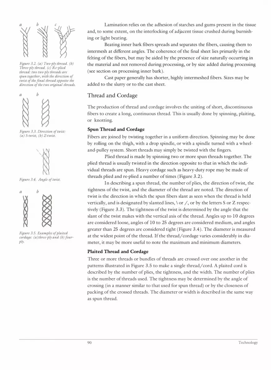
a b
Figure 3.2. (a) Two-ply thread. (b) Three-ply thread. (c) Re-plied thread: two two-ply threads are spun together, with the direction of twist of the final thread opposite the direction of the two original threads.
a b
Figure 3.3. Direction of twist: (a) S-tlVist, (b) Z-twist.
Figure 3.4. Angle of twist.
a b '\
Figure 3.5. Examples of plaited cordage: (a) three-ply and (b) fourply.
Lamination relies on the adhesion of starches and gums present in the tissue
and, to some extent, on the interlocking of adjacent tissue crushed during burnish
ing or light beating.
Beating inner bark fibers spreads and separates the fibers, causing them to
intermesh at different angles. The coherence of the final sheet lies primarily in the
felting of the fibers, but may be aided by the presence of size naturally occurring in
the material and not removed during processing, or by size added during processing
(see section on processing inner bark) .
Cast paper generally has shorter, highly intermeshed fibers. Sizes may be
added to the slurry or to the cast sheet.
Thread and Cordage
The production of thread and cordage involves the uniting of short, discontinuous
fibers to create a long, continuous thread. This is usually done by spinning, plaiting,
or knotting.
Spun Thread and Cordage
Fibers are joined by twisting together in a uniform direction. Spinning may be done
by rolling on the thigh, with a drop spindle, or with a spindle turned with a wheel
and-pulley system. Short threads may simply be twisted with the fingers.
Plied thread is made by spinning two or more spun threads together. The
plied thread is usually twisted in the direction opposite to that in which the indi
vidual threads are spun. Heavy cordage such as heavy-duty rope may be made of
threads plied and re-plied a number of times (Figure 3 .2) .
In describing a spun thread, the number of plies, the direction of twist, the
tightness of the twist, and the diameter of the thread are noted. The direction of
twist is the direction in which the spun fibers slant as seen when the thread is held
vertically, and is designated by slanted lines, \ or /, or by the letters S or Z respec
tively (Figure 3 .3 ) . The tightness of the twist is determined by the angle that the
slant of the twist makes with the vertical axis of the thread. Angles up to 1 0 degrees
are considered loose, angles of 10 to 25 degrees are considered medium, and angles
greater than 25 degrees are considered tight (Figure 3 .4) . The diameter is measured
at the widest point of the thread. If the thread/cordage varies considerably in dia
meter, it may be more useful to note the maximum and minimum diameters.
Plaited Thread and Cordage
Three or more threads or bundles of threads are crossed over one another in the
patterns illustrated in Figure 3 .5 to make a single thread/cord. A plaited cord is
described by the number of plies, the tightness, and the width. The number of plies
is the number of threads used. The tightness may be determined by the angle of
crossing (in a manner similar to that used for spun thread) or by the closeness of
packing of the crossed threads. The diameter or width is described in the same way
as spun thread.
90 Technology

Knotted Thread and Cordage
Fibers or bundles of fibers are knotted end-to-end to make a continuous thread.
This technique is typically used with long fibers, such as the monocot leaf fibers,
which may be up to 2 m long. Knotted threads are sometimes spun after knotting
(see, for example, the discussion of Okinawan banana fiber cloth in this chapter) .
Interworking Elements
The following is only an attempt to present the basic techniques of interworking
elements used in constructing artifacts. The variations and embellishments of these
techniques are endless. The basic interworking methods are linking, looping, wrap
ping, and crossing elements. Most constructions involve variations and combina
tions of these, and using them with different numbers of elements . For example,
knots are various combinations of linking, looping, and wrapping.
In constructions like binding, basketry, and weaving, the basic units of
fibers used in construction are called elements. Elements may consist of a strand of
plant material, a bundle of plant fibers, a spun thread/cord, a plaited thread/cord,
or a knotted thread/cord. A strand of plant material is an intact section of plant
material, such as a grass leaf, an epidermal split of bamboo or rattan, a strip of leaf,
or a strip of inner bark. A bundle of plant fibers is two or more strands or fibers
used as a single element, but that have not been spun, plaited, or knotted together.
Spun, plaited, and knotted thread/cords are described in the previous section.
Elements are either active or passive based on whether they are moving or
are worked around or over during construction. For example, in coiled basket con
struction, a passive foundation element is bound by an active element that links,
loops, or wraps. In macrame, all the elements are active at one time or another,
although for particular knots one element may be active and another passive.
Elements may be used singly or in small groups, such as in three-ply twin
ing. A large group of elements that are generally parallel and function identically
are called a set of elements. For example, the passive elements in twining are a set
of elements.
Interworked element construction may be open or tight. In open construc
tions, the elements have space between them. In tight constructions (also called
close constructions), the elements are drawn tightly together (packed) to create a
denser construction.
When examining an artifact to determine its construction, close inspection
of the configuration of elements is important, as the general visual appearance of the
faces of different constructions can be very similar. For example, the obverse face of
horizontal wrapping around a set of vertical elements looks exactly like the obverse
face of horizontal three-ply twining around a set of vertical elements, yet the two are
quite different in construction. Similarly, the obverse face of a form of wrapping,
commonly called wrapped twined weaving, can be identical in appearance to the
obverse face of a supplementary element decoration used on twining, commonly
called false embroidery.
Ruth E. Norton 9 1
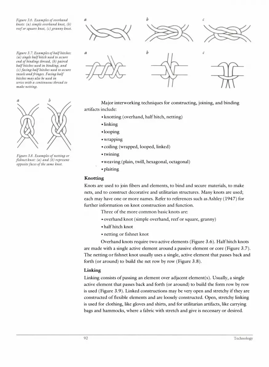
Figure 3.6. Examples of overhand knots: (a) simple overhand knot, (b) reef or square knot, (c) granny knot.
Figure 3.7. Examples of half hitches: (a) single half hitch used to secure end of binding thread, (b) paired half hitches used in binding, and (c) facing half hitches used to secure tassels and fringes. Facing half hitches may also be used in series with a continuous thread to make netting.
a
Figure 3.8. Examples of netting or fishnet knot: (a) and (b) represent opposite faces of the same knot.
a b c
a b c
Major interworking techniques for constructing, joining, and binding
artifacts include:
o knotting (overhand, half hitch, netting)
o linking
o looping
o wrapping
o coiling (wrapped, looped, linked)
o twining
o weaving (plain, twill, hexagonal, octagonal)
o plaiting
Knotting
Knots are used to join fibers and elements, to bind and secure materials, to make
nets, and to construct decorative and utilitarian structures. Many knots are used;
each may have one or more names. Refer to references such as Ashley ( 1947) for
further information on knot construction and function.
Three of the more common basic knots are:
o overhand knot (simple overhand, reef or square, granny)
o half hitch knot
o netting or fishnet knot
Overhand knots require two active elements (Figure 3 .6) . Halfhitch knots
are made with a single active element around a passive element or core (Figure 3 .7) .
The netting or fishnet knot usually uses a single, active element that passes back and
forth (or around) to build the net row by row (Figure 3 .8 ) .
Linking
Linking consists of passing an element over adjacent element( s ) . Usually, a single
active element that passes back and forth (or around) to build the form row by row
is used (Figure 3 .9) . Linked constructions may be very open and stretchy if they are
constructed of flexible elements and are loosely constructed. Open, stretchy linking
is used for clothing, like gloves and shirts, and for utilitarian artifacts, like carrying
bags and hammocks, where a fabric with stretch and give is necessary or desired.
92 Technology

Figure 3.9. Examples of linking: (a) simple linking, (b) twisted simple linking, (c) interlocked linking-in this example, each row passes over three other rows.
Figure 3.10. Examples of looping: (a) series of loops around a passive core; (b) simple looping; (c) twisted simple looping, (d) hourglass or f igure-oj-eight looping, (e) pseudoknit looping (also called crossknit looping or needle knitting).
a
=1}}}}�
c
Figure 3.11. Examples of wrapping: (a) simple wrapping, (b) horizontal wrapping around members of a vertical set of passive elements, (c) horizontal wrapping around two crossed sets of vertical and horizontal passive elements. This construction is often called wrapped twined weaving (for example, see Mason 1904), but it is not true twining or weaving.
a b c
a b c
d
e
Linked constructions may be dense, and flexible or rigid, if they are con
structed of stiff elements and/or are tightly constructed. Tightly constructed, flexi
ble fabrics of spun threads are used for clothing and containers. Tight construction
using stiff elements results in a dense, rigid sheet, such as found in some spear grips
and guards.
Looping
Looping consists of passing an element over itself to create a loop. A single active el
ement is usually used. The element may form a series of tight loops around a passive
element or core (Figure 3 . 1 0a) . This construction is found, for example, in button
holes and basket rims, and is used to bind edges to prevent unraveling. In the con
struction of textiles, nets, and basketry, interconnected rows oflooping are used
(Figures 3 . 1 0b to e ) . Looping in these cases is usually fairly open; however, tight
construction, and all degrees between open and tight, are found. Usually, intercon
nected rows of looping are interconnected, with the loop passing over the thread
between the loops of the previous row. In pseudoknit looping (Figure 3 . 1 0e) , the
rows are interconnected with the looping thread passing around the loops of the
previous row. Pseudoknit looping is usually fairly tightly constructed.
Wrapping
A single element may wrap around a passive element or core (Figure 3 . 1 1a ) . This
may be functional-to bind and secure material as in basket rims-or may be decora
tive-to cover structural elements with materials of a particular color or texture .
An active element may wrap around members of a set of elements (Figure
3 . 1 1 b) or around two or more crossing sets of elements (Figure 3 . 1 1 c ) to join the
members and sets. These techniques are used in constructing clothing, basketry, and
utilitarian artifacts.
Ruth E. Norton 93

Figure 3.12. Examples of wrapped coiling: (a) wrapped coiling, (b) wrapped coiling JVith a twist introduced JVhere wrapping element connects two foundation elements, (c) wrapped coiling with split foundation element.
Figure 3. 13. Example of looped coiling.
b
Figure 3. 14. Examples of linked coiling: (a) linked between foundation elements, (b) linked around foundation elements.
Figure 3. 15. Examples of simple twining: (a) even or regular twist, open and close, (b) alternating or countered twist, open and close.
a b c
Coiling
In coiling, an active element secures a passive foundation element in position. The
foundation is continuous and is coiled to develop the object shape. Coiling is fre
quently used in basketry constructions, usually with the foundation horizontal. It is
also used in constructing many diverse artifacts such as masks, figures, and utensils .
As the active element must be fairly fine and supple, and the foundation
elements are usually fairly sturdy and stiff, coiled constructions tend to be weakest
between foundation rows, and this is where damage in the form of splitting and
breaking of the artifact usually occurs.
There are three basic types of coiling:
• Wrapped coiling. The active element wraps around two or more founda
tion elements; alternatively, the active element wraps around one founda
tion and a portion of the adjacent foundation, splitting the foundation
(Figure 3 . 12 ) .
• Looped coiling. The active element loops around the foundation
element; the rows ofloops are interconnected (Figure 3 . 1 3 ) .
• Linked coiling. The active element is linked between or around the
foundation element(s) (Figure 3 . 14) .
Twining
In twining, a pair of active elements connect members of a set of passive elements.
Two active elements work together as a pair, one going in front of and one going
behind each member of the set of passive elements. The pair twists between each
passive element, so that, on the next passive element, the one formerly in front goes
behind and the one formerly behind goes in front.
Within each row, the twining pair usually twists in the same direction. Suc
cessive rows may twist in the same direction (even or regular twist) or alternate rows
may twist in opposite directions (alternating or countered twist) creating a different
surface texture (see Figure 3 . 1 5 ) . The rows of twining pairs may be tightly packed
(close twining) or spaced (open twining) .
a b
94 Technology

Figure 3.16. Examples of variations in twining: (a) paired and split passive elements, (b) crossed passive elements, (c) three-ply twining, an example of multiple-ply twining.
Figure 3.17. Twining incorporating horizontal and vertical sets of passive elements.
Figure 3.18. Examples of plain weave: (a) simple plain weave, (b) plain weave with horizontal elements more closely packed than vertical elements.
a b c
In basketry and textiles, the set of passive elements is usually vertical and is
sometimes called the warp, while the active elements are usually horizontal and are
sometimes called the weft (hence the term weft twining) .
Variations on simple twining may occur in the passive set of elements
(paired and split elements, crossed elements) and in the active twining elements
(multiple-ply twining; see Figure 3 . 16 ) . Another variation involves incorporating
an additional set of passive elements horizontally within each twining pair ( see
Figure 3 . 1 7) .
As the active elements must be fairly fine and supple, twined constructions
tend to be weakest across the twining elements, and damage in the form of splitting
and breaking often occurs between the passive vertical elements.
Weaving
Weaving comprises sets of elements interwoven parallel and perpendicular to the
edge (rim or selvedge) of the artifact. The following examples illustrate weaving
techniques used to construct nontextile artifacts. The use of the terms warp and
weft have been avoided here as their functional meaning in weaving does not always
apply to nontextile weaving. (For information on textile weaving techniques, refer
to Emery 1966, Seiler-Baldinger 1979, or to any of the many books available on
textile technology. )
Most nontextile weaving is done with two sets of elements crossed at 90
degrees. However, the use of three and four sets of crossed elements is not uncom
mon in basketry:
• two sets of elements (plain weave, twill weave)
• three sets of elements (hexagonal weave)
• four sets of elements (octagonal weave)
In plain weave (Figure 3 . 18 ) , elements cross each other in a regular over
one, under-one pattern. Variations include pairing elements, making one set of
elements more tightly packed than the other, and using sets of elements of different
diameter or width.
a b
Ruth E. Norton 95

Figure 3. 19. Examples of twill weave (vertical elements are stippled to make the weave patterns clearer): (a) even 2-2 twill, (b) even 2-1 twill, (c) 2-1 diamond twill, (d) 2-2 herringbone twill.
a
b
Figure 3.20. Examples of weaving using more than two sets of elements: (a) hexagonal weave, (b) octagonal weave.
Figure 3.21. Plain-weave plaiting.
b c
' . ..... ... .. .. ... . :,: . . , :; .�
:;.
In twill weave (Figure 3 . 19) , elements of one set cross over two or more ele
ments of the second set. The crossings of successive rows are offset, creating a diago
nal pattern (compare Figure 3 . 19a with Figure 3 . 1 Sa) . Twills may be described by
numbers that indicate the number of elements over which and under which a single
element runs-for example, even 2-2 twill (over two, under two), or even 4-1 twill
(over four, under one) . Twills in which the number of elements crossed and the
number of elements offset are consistent throughout the weaving are referred to as
even twills. Twills in which these are not consistent are referred to as broken or un
even twills. Some broken twills create geometric patterns such as the diamond and
herringbone twills illustrated in Figures 3 . 19c and 3 . 19d. In many baskets and mats,
intricate patterns are created by combining many variations of uneven twills.
Hexagonal and octagonal weaves are illustrated in Figure 3 .20.
Plaiting
In appearance, plaiting looks like weaving with two sets of elements-the only visual
difference being that the elements are interwoven diagonally (at 45 degrees) to the
edge (rim or selvedge) of the artifact (compare Figure 3 .2 1 to Figure 3 . 1Sa) . The
descriptive terminology used is the same as for weaving.
Decoration
Decoration may consist of patterns developed by variations in the interworking tech
nique. Examples include variations in twill weaves to develop geometrical patterns,
alternation of twist and number of plies in twining to create variations in texture and
relief, and crossing, twisting, or splitting passive elements to create open-work.
Decoration may be appendages, such as tassels, feathers, shells, and so on,
incorporated during construction. Decoration in the form of different colors and
textures may be achieved by using various structural elements or by incorporating
supplementary elements ( that is, elements incorporated into or added to the struc
ture, but that are not structurally important) .
Structural elements introducing different colors and textures may be single
or multiple . Discontinuous single elements of different colors are used to create
stripes and blocks of colors, as seen, for example, in the New Guinean billum (a
carrying bag usually constructed by looping). A single flat element may also be of
different color and texture on either side; this can be found in elements of split
stems and some barks where the epidermal side is smooth and shiny and the interior
side is fibrous and matte and of a different natural or dyed shade . If an element such
as this is twisted ISO degrees when twining or wrapping, for example, the different
sides are exposed. The same effect can be achieved by pairing flat elements of differ
ent colors and twisting them.
96 Technology

Figure 3.22. Examples of overlaid supplementary element decoration (supplementary elements are stippled): (a) supplementary element overlaid on split foundation wrapped coiled construction, (b) supplementary element overlaid on plain-weave plaited construction.
Figure 3.23. Example of lvrapped overlaid supplementary element decoration. Supplementary element wraps around obverse element of twining pair (supplementary elements are stippled): (a) cross section of (b) obverse face.
a
b
Figure 3.24. Example of imbrication. Supplementary element folds around obverse portion of wrapping element in wrapped coiled construction (supplementary elements are stippled): (a) cross section of (b) obverse face.
b
Supplementary elements incorporated into coiling, twining, weaving, and
plaiting techniques are common. Three of the frequently used incorporation tech
niques are overlay, wrapped overlay, and imbrication. Overlaid supplementary ele
ments lie on top of structural elements and are held in place by going under some
structural elements. Figure 3 .22 illustrates examples of overlaid decoration in coiled
and plaited constructions. Wrapped overlay supplementary elements are those that
wrap around the obverse face portions of structural elements . Figure 3 .23 illustrates
an example of this, which is sometimes called false embroidery. Imbrication, illus
trated in Figure 3 .24, is found in coiled constructions. The supplementary element
completely covers all structural elements on the obverse face.
Edges
Edges may be finished in a variety of ways. Some result from the natural turning of
elements during the course of construction, such as edges in knotting, coiling, and
looping, and some of the edges in plaiting and weaving.
Other edges consist of the cut ends of elements and must be finished in
some way to prevent unraveling. Finished edges vary from very simple to extremely
complex construction, but all are based on the basic construction techniques pre
viously described:
• introducing one or more rows of multiple-ply twining below cut ends
• folding element ends back and working them into the construction
• looping around element ends or around top rows of construction; or
looping with the element ends
• wrapping the element ends; top rows of construction may be included
in the wrapping
• plaiting with or around element ends; top rows of construction may be
included in the plaiting
Decoration and Finishes
Decoration may be structural-that is, incorporated into the structure of the artifact
during basic fabrication-or may be applied-that is, added to the structure after
basic fabrication. Finishes are used to modifY the surface texture, sheen, color, and
permeability of the artifact. Finishes may be either worked or applied.
Structural Decoration
Structural decoration is added to the basic structure at the time of construction and
is incorporated into the structure . (Refer to discussion in previous section. )
Ruth E . Norton 97
Decoration may consist of supplementary elements (bundles, strands, or
cordage used to create color patterns or differences in texture) interworked in the
structure. Some examples are imbrication in coiled basketry, overlaid elements in
plaited or woven work, and doubled elements of different colors in twined work.
Other decorative elements such as feathers and tassels may be knotted or woven into
the structure at the time of construction. Structural decoration may also include pat
terns impressed or embossed into the surface .
Applied Decoration
This consists of decoration applied to, rather than incorporated into, the basic struc
ture. Applied decoration includes: material (like feathers, tassels, fringes, quillwork,
beading, and shells) that is attached with thread or cordage (see Seiler-Baldinger
1979 and Buck 1927,1950,1957 for examples of specific techniques used); thread,
cordage, and fibrous strands that are stitched to or around the artifact in embroi
dery-like fashion; and decorative elements (such as metal foils, paint, shells, feathers,
and other plant materials) that are adhered to the surface.
Dyeing has been included in general processing procedures because, more
often than not, it is done before or during construction. However, dyes may also be
applied after construction-either by soaking the material in a dye bath or by rub
bing dye over its surface. Some dyeing techniques, such as those using wax, folding,
and sewing resists, are done after construction.
Applied Finishes
Applied finishes include added materials that sit on and/or penetrate into the sur
face, like oils, varnishes, resins, lacquers, wax, and paint. (Note: Resins and waxes
may be applied to artifacts to seal joints or to waterproof. In such cases they should
be viewed as a functional part of the artifact construction, not just as a decoration
or finish. )
Worked Finishes
Worked finishes result from techniques, like polishing and burnishing, which actu
ally move the structural material to create a particular texture and sheen.
Cultural Modification of Artifacts
Cultural modification of an artifact is as important as its initial fabrication. Artifacts
are inevitably modified during use. Smoke, dirt, and oils are deposited on and
absorbed into the surface; handling can further burnish these to a hard, smooth pa
tina. Clothes absorb body oils and dirt and develop creases and folds when worn.
Abrasion, nicks, and scratches occur during use. Food residue is deposited on and in
containers, utensils, and cooking vessels. Tool surfaces may contain minute deposits
of the plant, animal, and mineral materials which they worked. Artifacts associated
with religion and ritual may be anointed, buried, and repainted.
98 Technology

Broken and damaged artifacts may be discarded or repaired. Repair may
consist of alteration using different materials-as in the use of resin to mend cracked
wood vessels-or may consist of reconstruction using the same or similar materials
as in the reweaving of damaged areas in a mat.
Artifacts may be modified in form as their ownership or use changes.
For example, a food-collecting basket strap originally used as a tumpline may be
replaced with a hand-held one as food sources change from those gathered to those
purchased at market.
Some artifacts are not only physical documents of a culture, but have inher
ent or invested powers and properties within their cultural context. These intangible
properties of an artifact, although not cultural modifications of the physical fabric of
the artifact, are important properties related to cultural use and context and must be
considered in the handling, treatment, and accessibility of the artifact.
Plant Materials Used in Artifact Construction
Parts of a great number of plants are utilized in the manufacture of artifacts. The
morphology, anatomy, and composition of organs of major plant groups are fairly
distinctive and determine the physical properties of those organs. It is therefore
most useful to consider the processing and use of plant material according to the
major organs used (stems, trunks, roots, leaves, seeds, fruits) and, within those
organ types, according to major plant groups (dicot, monocot, gymnosperm, and
lower plants) . Because processing and use within these groups vary culturally and
with the particular plants utilized, specific examples illustrate processing, construc
tion, and use where generalizations would be of little value. (Refer to comments on
the organization and content of this section in the introduction to this chapter. )
Stems, Trunks, and Roots
The seasoning, conversion, and working of woody tissue is well covered elsewhere
and will not be discussed here. (Refer to introductory texts on wood technology
and finishing for the decorative arts, such as Hoadley 1980 and Hayward 1978,
1979a, 1979b, and to monographs on the material culture of specific cultural
groups . ) The whole bark is used extensively in artifact production by some cultural
groups. Its use is discussed through examples: the use of birch bark in the northern
hemisphere and the use of stringybark and paperbark in Australia. The processing
and use of the inner bark for cordage and sheet production is discussed in general
terms; the reader is referred to the literature on the material culture of specific cul
tural groups for further information on plant sources, processing, and use . Monocot
stems are important sources of material for domestic and commercial products.
Their processing and utilization are illustrated using bamboos, rattans, and sedges.
The stem and adventitious root system comprising the trunk of the tree fern are
given as examples of the use of lower plants in artifact production.
Ruth E. Norton 99

Bark
Bark is used relatively intact in the production of artifacts and is also an important
source of fiber. The use of inner bark fibers alone will be discussed in the next sec
tion; here the use of the whole bark or of the outer bark only will be discussed. The
form of the layers in the rhytidome (outer bark) is the most distinguishing character
istic of bark utilization. Also of importance is the bark's strip ability along phello
derms or along the vascular cambium. Barks used in artifacts are usually those with
very thin, broad sheets, like birch, cherry, and paperbark, and those that are very fi
brous, like cedar and stringybark.
Birch Bark
The bark of the paper birch (Betula papyrifera) was extensively used by some Native
North American groups for utilitarian and religious artifacts. After the arrival of the
Europeans, artifacts in European styles and incorporating trade materials were also
made. Gilberg ( 1986:68) describes birch bark scrolls made by a religious fraternity
of the Ojibway people. The outer bark was stripped around the circumference or,
occasionally, down the length of the tree. Sheets of bark were sewn together with
split spruce root or bast fiber cord through holes punched in the overlapping edges
to achieve scrolls of the desired length. Ends of the scrolls were often bound with
endsticks. Pictographs were impressed or incised on both sides of the bark, though
usually on the cambium side, using sharp implements. Occasionally, scrolls were
rubbed with red ocher or vermillion, or particular images were painted on them.
In India, birch bark has been used for manuscripts for over two thousand
years . Agrawal ( 1984 : 1 3, 16-1 7) writes that the inner bark (probably referring to
the inner surface of the bark) was used for writing. First, the bark was peeled off the
tree and dried. The surface was then oiled and polished to produce a smooth writ
ing surface. Finally, the sheets were cut to the desired size. Most sheets were kept
loose between wooden boards; sometimes the sheets were folded and bound or
were pierced and threaded like palm leaf manuscripts. Smaller sheets were folded
and worn in amulets. The usual writing material was carbon black ink prepared by
boiling carbon from burned almond shells with cow's urine.
Rymar ( 1978 : 1-3) reports that the use of birch bark in Russia in buildings,
kitchen utensils, and household objects predates its use as manuscript material in
the ninth century. The manuscripts are found as scrolls. Processing of the bark as
described by Rymar is not altogether clear. The bark was stripped off "an ungnarled
part of a birch of medium thickness growing on solid rising ground" and was
scoured (boiling in hot water for one hour is recommended) . In the eighteenth cen
tury only the innermost layer was used to make thin manuscripts; earlier manuscripts
from the Novgorod area are thicker. Writing was done by impressing or incising the
inner surface with pointed bone, wood, or metal tools.
Stringybark
The Australian Aborigines utilized whole sections of bark for dwellings, canoes,
containers, paintings, and religious figures, and bark strands for binding, cordage,
costumes, and containers.
1 00 Technology

Stringybark (Eucalyptus sp. ; E. tetradonta is the most frequently cited) is
thick and fibrous. (Refer to Chattaway 1955 for a detailed discussion of the anat
omy and composition of Eucalyptus bark. ) It is stripped from the tree by cutting the
desired section at the top and bottom with a sharp tool, slitting down the sides with
a pointed stick, and levering off the sheet. The whole bark, from the vascular cam
bium outward, is removed and is fairly pliable when green. It is often placed over a
fire to aid in flattening and shaping it for use in artifacts such as canoes and bark
paintings; the heat and steam generated in the green bark make it more pliable.
Canoes of stringybark vary in design from simple, large (3 m to 5 m) sheets
of bark with pointed ends to those with bound and shaped ends and thwarts.
Sandale and Peterson ( 1969 ) document a canoe made in Arnhem Land in Northern
Australia for use in marshlands that was 2 m to 3 m long and about 1 m wide. A
large stringybark tree with a long straight trunk was used. The lower cut in the bark
was made about shoulder height and the upper cut was made by standing on a
forked tree ladder. One longitudinal split was made with a long pointed pole by
inserting the end under the bark of the lower cut and pushing it up the length of
the tree to the upper cut. The whole bark was peeled off around the circumference
of the tree using the pole as a lever. The sheet of bark was trimmed to the desired
length at the tree site and carried to the edge of the marsh. A hearth was made on
the wet ground with material from an old termite mound, and a small fire was
started. One third of the bark was placed inner side down over the fire; after a wIllie,
the bark was turned placing the outer side down. When considered sufficiently
pliable, the end was lifted from the fire, folded in half lengthwise, and wedged
between two stakes placed upright in the ground a couple of inches apart. The tops
of the stakes were bound together to pull the two halves of the bark end tightly
together. Binding strands were stripped from the inner bark side of stringybark and
trimmed to the desired size-several millimeters thick and about a centimeter wide .
Slits were pierced through both layers of bark, and the binding strand was sewn
through them with back stitches. The stern complete, the process was repeated to
form the bow. However, for the bow, grass was placed between the bark halves to
make a tighter join, and the top corner of bark was trimmed before the end was
sewn. The bark was then trimmed further to make the bow pointed. A thwart was
made by tying a stringybark strip across the middle of the canoe and inserting a stick
under it. When in use, the canoe rides very high in the water; the spread of the
middle bows the canoe so the bound ends ride above the water line (see also
Thomson 1939) .
Altman ( 1982 : 14) describes contemporary painting on bark by the
Gunminggu men in the Northern Territory, Australia. Sheets of stringybark are
collected in the dry season; they are flattened by briefly heating them over a fire and
by weighting them on a flat surface for several days. The inner bark surface is
smoothed with sandpaper. Top and bottom ends may be bound between two sticks
to help prevent warping. Figures are sketched in with white paint using a thick
brush made from stringybark. Red ocher, yellow ocher, and charcoal black paint are
applied with a very fine brush made of trimmed grass. The paint binder used is ei
ther a poly(vinyl acetate) emulsion or acacia gum. Contemporary artists' painting
methods vary with regional and individual styles. Older barks were painted with
Ruth E. Norton 1 0 1
pigments bound with a variety of media, such as natural gums, orchid tuber juice,
or egg yolk, which yielded generally very lean, matte paints.
Dawson ( 1881 : 14) describes the water bucket made by Aborigines in
Victoria, Australia, "formed of a sheet of fresh acacia bark, about twenty inches long
by twelve broad, bent double and sewed up at each side with kangaroo tail sinews,
and the seams made water-tight with an excellent cement, composed of wattle gum
and wood ashes, mixed in hot water. After the bucket is made it is hung up to dry,
and the contraction of the inner bark causes the vessel to assume a circular shape
which it retains ever after. It is carried by means of a band of twisted wattle bark
fixed across its mouth." Similar buckets made from stringybark on Bathurst and
Melville Islands are painted with red and yellow ocher, white, and carbon black
pigments (McCarthy 1974:49) .
Paperbark
The Australian paperbark (Melaleuca sp . ; M. leucadendron is the most frequently
cited) has thick bark, the rhytidome of which consists of many layers of thin, broad
sheets. The bark is used to make sandals, containers, knife sheaths, religious figures,
canoes, and so on. Knife sheaths were made by Western Australian Aborigines by
wrapping wide strips of the paperbark around blades and securing them by tightly
wrapping with spun cords made of human hair. White pigment was applied over
much of the wrapped areas. Sorcery figures about a meter long were made of strips
of paperbark folded and wrapped to shape. Final bindings to secure the paperbark
were done with sturdier, more fibrous bark. Appendages of wrapped paperbark were
secured with wool yarn.
Inner Bark
The inner bark of some plants contains considerable quantities of thick-walled
sclerenchyma fibers. These are extracted and utilized universally. Fiber length,
composition, strength, and overall color and texture differ considerably according .
to the fiber source and processing.
Inner bark fibers are primarily ( 1 ) used intact or separated into strands that
are used as is for decoration or binding or are spun into cordage, (2) beaten into
sheets (barkcloth, barkpaper), or ( 3 ) soaked and beaten to produce pulp for casting
sheets (paper) .
Inner bark fibers are collected from both cultivated and noncultivated
plants. If the plants are cultivated, it may be because they are an introduced species,
because a ready supply is desirable, or because cultivation is necessary to produce
particular qualities. Depending on regional tradition, the bark is harvested either by
stripping it from the living plant or by cutting the plant and removing the bark. Pre
liminary processing generally involves removal from woody tissue, removal of outer
bark, and retting or cooking. The order in which these things are done varies consid
erably, depending on tradition, fiber source, and end use .
Decoration, Binding, or Cordage
Unbeaten inner bark strips from the sachi tree (Aguilaria agallocha) are used for
manuscripts in India. Processing varies regionally, but involves soaking or boiling,
removal of outer bark (in one area it is lightly beaten), drying, dyeing with sulphide
102 Technology

of arsenic, and polishing (sometimes with a paste or oil size) or sanding (Kathpalia
1966:57-58 ) .
The inner bark of Hibiscus sp. and members of the nettle family (Urtica
ceae) are used for decoration, binding, and cordage . Mter retring and drying,
hibiscus inner bark readily separates into thin sheets that are used for decorative
tassels and applied decoration and are spun into cordage . The inner bark fibers take
dyes readily. The inner bark of some nettle species (for example, Touchardia
latifolia, Pipturus sp . , and Boehmeria sp . ) is cleaned immediately after stripping
from the plant by scraping both sides to remove the outer bark and push out sap.
When dry, narrow strands are torn off and spun.
Barkcloth and Barkpaper
Beaten inner bark sheets are/were made in the Pacific area, Central and South
America, Asia, and Mrica. Although the inner bark of many plants has been used to
some extent for beaten barkcloth or paper, those most commonly used appear to be
paper mulberry (Broussonetia papyrifera), fig (Ficus sp. ) , breadfruit (Artocarpus sp. ),
and, to a lesser extent, members of the nettle family (Urticaceae) .
Steps in Processing Barkcloth and Barkpaper
1 . Removal of outer bark. This is usually done when the bark is fresh and may be
preceded by soaking or retring.
2 . Processing of inner bark. There may be no special processing or i t may consist
of soaking, retting, cooking, or preliminary beating.
3. Beating. Pounding between hard surfaces separates and spreads and, to varying
extent, breaks fibers. Beater and anvil materials vary; they usually consist of
wood and/or stone . Patterns on the surfaces of the beater vary depending on
the stage of beating and desired texture . Degree of bearing varies considerably,
ranging from very stiff, thick sheets with little fiber reorientation, to very thin,
gossamer sheets with fine, short, very reoriented fibers. Final beating of flat or
rolled sheets is important to the texture of finished sheet.
4 . Joining of beaten strips. Strips may be joined in a number of ways:
• felting: beating strips together, may be parallel or crossed
• pasting: using paste (usually a starch, sometimes a gum) to join sheets
edge over edge
• sewing: joining strips by stitching
• combined techniques: for example, several sheets may be stacked and
felted together to make a thicker sheet that is joined to others by pasting
or sewing; sewing is also used to reinforce sheets
5 . Decoration. Some of the techniques used for finishing and decorating the
sheets include :
• dyeing of the whole sheet, localizeq areas (rubbing over pattern board), or
surface only (rubbed on, dyed layer felted on)
• application of paints: freehand, stencilled, stamped, lined
• collage: pasting cut design onto sheet
Ruth E. Norton 103

• oiling: saturating with drying or semidrying oil
• sizing: applying plant starch or gum
• perfuming: applying essential oils
• polishing: burnishing with stone or shell
• applying decorative elements: feathers, shells, coconut shell disc, cloth and
beaten bark tassels, etc.
• joining layers of full sheets by sewing
Uses
Barkcloth sheets are used for bedding, clothing, ceremonial presentations, burial,
manuscripts, paintings, and so on. Barkcloth is also used in the construction of
three-dimensional artifacts in which it may be molded around wood, used in basket
ry or figures, or folded and bound for containers and wrapping. Finally, strips of
barkcloth sheet are spun for binding and cordage .
A great deal of detailed literature is available on beaten inner bark sheets,
including crosscultural and local anthropological studies as well as publications of
national museums and crafts councils in countries producing barkcloth and bark
paper, to which one can refer for information on manufacture in specific areas. For
examples of such sources, refer to Koojiman ( 1963,1972) , Kennedy ( 1972 ),
Mosuwadoga ( 1978 ) , Bell ( 1983), and Wilcox ( 1985) .
Paper Cast from Pulp
The process of pulping and casting fiber to make paper is mentioned here because it
is an important use of inner bark fibers-and of monocot stem and leaf fibers such
as those from bamboo, banana, and palms. Cast paper has been made and utilized
for centuries for manuscripts, clothing, and modeling. For further information, refer
to the history and technology of papermaking literature.
Monocot Stems
The stems of monocots utilized for artifacts range from fine wisps to large rigid
poles. Anatomically, they are most readily characterized by long, dense longitudinal
fibers and fibrovascular bundles, often closely packed toward the epidermis of the
stem. The resulting physical properties of longitudinal strength and suppleness, ease
of splitting longitudinally, and smooth dense exterior have made them an invaluable
resource for the production of artifacts. The value of some, like bamboo and rattan,
is readily evident not only in the quantities utilized, but in the variety of construc
tion techniques used and the variety of end uses to which they are put-from major
buildings to intricate jewelry. The processing and manufacture of artifacts from bam
boo, rattan, and sedge are discussed as examples of the utilization of monocot stems.
Bamboo
Bamboos are members of the Poaceae or grass family, growing singly or in clumps
and ranging in size from very short and thin species to species with heights of up to
23 m and culm diameters of up to 23 cm. Like most monocots, they exhibit only
primary growth. Culms reach full size in a matter of months, but take several years
to mature . Maturation consists of hardening and strengthening through thickening
104 Technology

a
culm
b
c
r culm sheath
I I I ��
n cuticle
�
\ sheath scar at node
Figure 3.25. The anatomy of bamboo: (a) major organs, (b) longitudinal section of culm at node, (c) cross section of culm lvall sholVing outer area lVith very dense, small, tmdeveloped fibers and fibro-vascular bundles.
of cell walls, increasing crystalline orientation of cellulose, lignification, and deposi
tion of silica.
The major organs of bamboo (Figure 3 .25a,b) are the culm or stem ofusu
ally hollow internodes and solid nodes from which grow the culm sheaths, branches
and leaves, and flowering organs. The root system comprises a dense tangle of fine
rootlets and thick rhizomes. Although most parts of the bamboo are used, the culm
is the most widely utilized part for the construction of artifacts.
The culm consists of longitudinally oriented fibrovascular bundles in a
matrix of parenchyma tissue (about 50% parenchyma, 40% fibers, and 10% vascular
cells; Liese 1980a: 1 6 1 ) . The fibrovascular bundles at the outer surface are small,
closely packed, and primarily fibrous (Figure 3 .25c) . The fibrovascular bundles of
the major part of the stem are fairly regularly spaced, and the vascular tissue is fully
developed. The arrangement of the fiber sheaths surrounding the vascular tissue
differs between genera and can be used to identifY individual bamboo genera (Liese
1980a: 162-163) . The exterior surface is usually a single layer of epidermal cells cov
ered with a thick waxy coating; the inner surface is a layer of sclerenchyma fibers.
Most movement of material through the culm is longitudinal, with radial
conducting tissue occurring only to a minor degree at the nodes, a feature that
greatly affects seasoning and penetration of preservatives. In some cases, the high
silica content on and within bamboo tissue makes the material difficult to work.
Because bamboo is an important commercial crop for the construction, handcraft,
and paper industries in many countries-especially in Asia-the composition and
properties of bamboo have received considerable attention (see Lessard and
Chouinard 1980 text and bibliography for composition, extractives, fiber structure,
moisture content, strength, and so on) .
Modification During Growth
The shape, color, and sheen of bamboos vary widely from species to species and are
exploited in artifact creation (for examples, see Marden 1980 :516-521 ) . The shape
and color of bamboo may be modified during growth and immediately after harvest
ing. Sharma ( 1980: 1 1 8 ) reports: "Japan has successfully grown artificially shaped
bamboos . . . A wooden frame (mould) is made in the desired shape, and it is in
stalled on the young bamboo shoot. Mter about six months the frame (mould) is
removed from the bamboo, which has taken on the desired shape. The culm is cut
when it matures . . . In Japan and Taiwan . . . a mixture of sulfuric, nitric and hydro
chloric acids with water and clay is prepared and painted over the green culm with a
brush; this produces ornamental patches on the culm."
Harvesting
As immature culms are very prone to cracking on drying and have not attained full
strength, the harvesting of mature culms seems preferable . In most areas, bamboo
grows year round and can be harvested at any time. Recommended harvest time
appears to be related more to drying and seasoning factors than to bamboo growth.
In Japan, the best season for harvesting is late fall, thus avoiding insect damage
(especially Dinoderus minutus); insect attack is most severe from April to June
(Lessard and Chouinard 1980:49 ) . For commercial harvesting in the Philippines,
bolos (large heavy iron knives) and hatchets are used. "Culms, three or more years
Ruth E. Norton 105

old, are ready for harvesting, those of unarmed bamboos usually being cut close to
the ground and those of bamboos such as Bambusa blumeana being cut 2-3 m.
above the ground (just above the dense growth of spiny branches . . . the very thick
walled portion of the culms being left in the clump) . Harvesting is usually done dur
ing the dry season, from November to May" (Lessard and Chouinard 1980:78-79 ) .
Harvesting practices for noncommercial, home use of bamboo may differ.
Seasoning: Drying) Traditional Seasoning) Commercial Seasoning
Seasoning involves not just drying of the culm, but processing to improve its dura
bility. Seasoning is generally concerned with reduction of splitting upon drying and
with improving the culm's resistance to insects and fungi.
Drying is usually done in the open air by laying the bamboo on the ground
or by stacking in well-ventilated areas. Care must be taken against too-rapid drying,
which can lead to splitting, cracking, and collapse, or too-slow drying, which can
lead to fungal and bacterial attack with resulting staining and loss of cohesion and
strength. Successful drying appears to be species- and age-related and presumably is
dependent on the density and moisture content of the green culm. Studies by the
Indian Forestry Research Institute (Lessard and Chouinard 1980:42 ) on air drying
of nine species indicate that drying was complete in three months of clear weather.
The mature culms of four species dried with little cracking; other species and all im
mature culms suffered severe cracking and collapse. Accelerated drying over open
fires is also reported, and the use of kilns has been investigated for large-scale com
mercial interests.
Tamolang et al. ( 1980:198) report that care must be taken in placing or
stacking drying bamboo to prevent the development of bends. Bent green culms
can be straightened by weighting them during drying, either by placing them hori
zontally under weights or by hanging them vertically with weights tied to the bot
tom end; this takes two to four months. A faster method is to "hold the curved
portion over a charcoal fire or to apply a blowtorch to it. Care must be taken to pre
vent the culm from being scorched. Cooling is best accomplished by the application
of a cold wet cloth."
The most common (or at least the most frequently mentioned) traditional
seasoning is aimed at making the bamboo less attractive to insects, particularly the
powder-post beetle, Dinoderus minutus) by reducing the starch and sugar content of
the bamboo. Liese ( 1980b : 166) mentions an investigation on bamboo harvested
during the dry season and after flowering when the starch contents were depleted,
which claimed that the extent of beetle damage was related to starch content. How
ever, he felt that further investigation is necessary.
Tamolang et al. ( 1980: 197) recall that: "It is the common belief of carpen
ters that flies swarming over green and newly worked bamboo are a sign that the
particular bamboo is not durable. Soaking bamboo in seawater or running water for
two to three months [several weeks was reported elsewhere] , as practiced in the
rural areas, reduces its starch content and, consequently, lessens its attractiveness to
the beetles ." Of the soaking method, Liese ( 1980a: 169) warns that, though com
monly practiced, it "does not increase the durability against termites and fungi and
that the submergence in water may lead to staining of the bamboo." He relates
another method of reducing the culm starch content by cutting the culm at the base
106 Technology

but leaving the branches and leaves intact for some time ( 1980a: 1 68 ) . The leaves
continue to assimilate starch stored in the stem, thereby reducing its content.
Traditional seasoning methods in Malaysia are reported to be either immer
sion in water to remove food substances by fermentation or smoking over a fire
(Lessard and Chouinard 1980:94) . Liese ( 1980b: 168) also notes that culms are
sometimes stored above fireplaces and become black with smoke deposit. He sug
gests that toxic agents in the smoke may inhibit insect attack or that the heat may
break down the starch.
Commercial seasoning is directed toward increasing the bamboo's resis
tance to cracking and to insect and fungal attack. Studies were done in India to re
duce cracking of bamboo culms used for handcrafts (Lessard and Chouinard
1980:42) . Whole green culms of Dendrocalamusgiganteus were soaked in 50%
solutions (presumably aqueous) of polyethylene glycol- lOOO. No times were related,
but after treatment, no cracking occurred with air drying.
From the moment of harvesting, bamboo is very susceptible to attack by
termites and the powder-post beetle, and by brown rot, white rot, and soft rot
fungi. Commercial processing at the time of harvesting aims to inhibit biological
attack by the application of residual inhibitors and biocides. The application of
chemicals, such as creosote, boric acid, zinc chloride, copper sulfate, mercurials,
Chlorden, Dieldren, and DDT, has been reported. The main difficulty encountered
is in developing practical and economically feasible methods of achieving effective
penetration of the preservative into the green bamboo tissue. Surface treatment is
inadequate because of the dense and waxy outer layer of the culm. Penetration by
soaking and by forcing the preservative through the vascular tissue with gravity or
pump pressure has proved effective and feasible in the field. The consequences of
treatment of bamboo to be used for handcrafts and for cooking and food handling
do not appear to have been considered.
Uses
All parts of the bamboo are used: the leaves for thatching, fodder, and paper pulp;
the culm sheath in lining hats and sandals; the shoots for food; the sap for medi
cinal purposes; and the culm for anything and everything. Even the rhizome is uti
lized: "The rhizome of D. hamiltoni with slight trimming and dressing, is an exact
replica of a rhinoceros horn, which fetches a fabulous price as an aphrodisiac. Only
an expert can differentiate between the imitation rhino horn and the real; this nefari
ous use, however, needs to be discouraged" (Lessard and Chouinard 1980:34) .
Bamboos are among the most versatile plant materials in existence. Table
3 . 1 indicates some of the ways in which humans have taken advantage of bamboo's
remarkable adaptability.
Ruth E. Norton 107

Table 3.1 . Species of bamboos and their uses in Indonesia (excerpted from Lessard and Chouinard 1 980:66).
� "' "' ::l S ...
c:: -; 0 B OJ ... .::: � .;:: J.t "' � � ::l S � 0 a C) ... .. s 0 "' -; � � 0 OJ -; 0 "' ::l rJ) c:: ... OJ E-< "C .9- c:: .::: .... "C OJ c:: b/) 0 "' B .... 0 p., 0 rJ) ] .s .S OJ :§ U U b/) 0 'J:j � u ... :a :E .... � .... u OJ '2 � :a .. ..>: �
OJ .Ll "' OJ :a ::= .Ll "' .... OJ ... .. :a ::l Q,. e ::l 0 .. ::l � .!:1 � .... .. OJ Species � E-< � p;. :z:: p;. E-< iJ;l � p., � 0
Arundinaria japonica • • • Bambusa arundinacea • • • • B. atra • • • • B. blumeana • • • • • B. glaucescens • • • B. polymorpha • • • B. vulgaris • • • • • • • Dendrocalamus asper • • • • • • • • • Dinochloa scandens • • Gigantochloa apus • • • • • • • • • • G. atter • • • • • • • • • G. afr. atter • • • • • • • • G. verticillata • • • • • • • • Nastus elegantissimus • • Phyllostachys aurea • • P. nigra • Schizostachyum blumei • • • • • • • S. brachycladum • • • • • • • • • S. caudatum • • S. lima • • • • • • S. zollingeri • • • • • • • • Thyrsostachys siamensis •
Whole sections (usually an internode plus one or both of its adjacent
nodes) and radially split sections of bamboo are used as is; they may be cut, carved,
incised, dyed, polished, lacquered, or painted. To take dyes, oils, and many applied
surfaces, it is necessary to remove the cuticle and sometimes the very dense exterior.
Normally whole sections are taken from the culm. Exceptions to this practice in-
clude, for example, fine net undershirts made in China in which very small tubes,
probably taken from branch internodes, are used. During construction of the net
with fine thread, short lengths of very thin internodes are strung onto the thread
between each knot as shown in Figure 3.26 (Lubke 1969:2 1 ) .
Tangentially split strips, usually including the epidermis or the layer just
below it, are used in binding, weaving, and basketry construction techniques. The
split strips are strong and flexible . Sometimes they are soaked, steamed, and heated
just prior to using to make them even more flexible. Subepidermal splits receive dyes
well. Bark, wood, leaf, and tuber extracts, burial in black mud (resulting in an iron
108 Technology

Figure 3.26. Detail of Chinese net undershirts with bamboo internode tubes.
a
B �-__ _ nod,
b cuticle � �<� Figure 3.27. The anatomy of rattan: (a) rattan stem with leaf sheaths removed, (b) segment of cross section of stem showing evenly spaced ftbrovascular bumdles.
tannate black), commercial dyes, soot with vegetable gum and resin, and natural res
ins have been used to dye and varnish the splits.
Bamboo culm fibers are used for textiles in some areas (Lubke 1969:21 ) .
Young culms are split, soaked, and peeled to expose the fibrous inner tissue. This is
chewed, dried, and scraped to extract the fibers. The fibers are tied end to end to
make continuous thread.
Rattan
Rattan is the collective name for climbing members of palms in the tribe Lepido
caryoideae. Rattans occur in tropical forests and vary in habitat and size from small
undergrowth species to large climbing species with stems well over 100 m in length.
The stems consist of solid nodes and internodes and are covered with several layers
of spiny leaf sheaths (the spreading base of the leaf petiole that wraps around the
stem), each sheath covering several internodes. Leaves vary considerably in size,
shape, and length of petiole. Flowering organs consist of flowers on branches emerg
ing from at least one major bract (modified leaf that envelops the developing flower
ing organ and often a series of smaller bracts) . Refer to Dransfield ( 1979 :7-16) for
discussion of the general morphology of organs.
The rattan stem consists of solid internodes and nodes. Except for the base
and tip, it is fairly consistent throughout its full length in diameter, internode
length, and density. The internodes consist of vertical fibrovascular bundles sur
rounded by parenchyma tissue . The fibrovascular bundles are more densely packed
near the epidermis (see Figure 3 .27) .
The epidermis is dense, heavily sclerified and cutinised, may have a very
high silica content, and is covered with a waxy cuticle . The vascular tissue and epi
dermis are somewhat disarranged at the nodes to accommodate growth of the leaf,
climbing organs, and flowering organs. The evenness of distribution of fibrovascular
bundles in the core, the density and lignin content of the core and epidermis, and
the degree of sclerification and silica deposition in the epidermis vary from species to
species, resulting in differences in flexibility, strength, and brittleness.
Uses
Most of the organs of rattan are utilized to some extent. Dransfield ( 1979:27)
comments that stem uses are so legion that any catalog other than the broad catego
ries of matting, furniture, cordage, basketry, and utilitarian objects would be incom
plete. The spiny leaves, petioles, and climbing organs are variously used for graters
and traps. Dragon's blood-a deep maroon resin exuded by the fruit scales of a few
rattan species-is used as a dye and varnish. Refer to Dransfield ( 1979 ) and Menon
( 1980) for further details on regional utilization of rattan.
Collection and Initial On-Site Processing
Most rattan is collected in the forest. The base of the stem is cut, the stem pulled
down from the forest canopy, and the upper, immature portion discarded. The
spiny leaf petioles are loosened and removed by twisting or bending the stem and
scraping. During this process, the brittle outermost layer of heavily sclerified and
silicified epidermis may also be removed. If this cleaning cannot be done immedi
ately after harvesting, the canes are soaked to keep them moist until they can be
Ruth E. Norton 109

cleaned. The cane is cut into uniform lengths of up to several meters and dried
quickly in the air or over a fire to prevent staining by fungal growth.
Processing
Rattan for commercial use may undergo further processing to make it cleaner and to
give it greater durability. Menon ( 1980:25-30) reports that, in Indonesia, rattan
may be washed, or washed and fumigated with sulfur dioxide, or washed, fumi
gated, and boiled in mud or mixtures of diesel and coconut oil. The canes are then
polished and air dried to a moisture content of5% to 1 0%. In Singapore and Hong
Kong, rattan imported from Indonesia is further treated with aqueous sodium hypo
chlorite and hydrogen peroxide solutions and gaseous sulfur dioxide to alter and
even its color. In Malaysia, canes are boiled in mixtures of coconut, diesel, and palm
oil and in India they are rubbed with linseed oil. Boiling in oil is believed to reduce
the canes' moisture content and to make them more durable by removing the natu
ral gums and resins. Washing, fumigation, and bleaching are done to improve the
canes' appearance.
Rattan is sold whole or is split to separate strips of the outer layer of the
stem from the core and sold as split and core rattan. Refer to Dransfield ( 1979:20-
30) and Menon ( 1980:41-42 ) for more information on splitting and grading rattan
and on preferred rattan species for commercial use.
In villages, basket weavers would collect their own rattan, or purchase it
from a local collector, and no further processing other than cutting, splitting, and
trimming to prepare elements of the desired size appears to have been done.
In preparing rattan to weave a bango, a woven backpack made by men of
the Ifugao Province, Philippines, lengths of bamboo about 3 m long and 5 cm in di
ameter were purchased locally. These were cut to 1 m lengths. The exterior portions
were split off and trimmed to the desired size by shaving with a knife. The core of
the rattan was cut into thicker strips for the base and external ribs of the bango (Ng
1978:37-38) . The rattan strips (epidermal splits) of baskets of this type are generally
about 5 mm wide and 1 mm thick, and all those examined were thinned by shaving
off the core side of the strips and were woven with the epidermal surface on the exte
rior of the basket. The only epidermal areas removed were the slight bulges just
below the nodes.
Designs in woven work are created by the weaving pattern and the use of
dyed strips contrasting with the natural color. Courtenay and Chadwick ( 1983) re
port that, unlike bamboo, the rattan cuticle is said to dye well. The Punan of
Borneo dye rattan red with the extract of boiled rattan seeds and black with the
boiled roots and leaves of tarum. Courtenay and Chadwick further report that rattan
basketry and mats are highly valued and damaged ones are mended with great care
and skill.
Sedges
Sedges are herbaceous monocot perennials in the family Cyperaceae . The sedge
stem is three-sided or cylindrical with a shiny epidermis and a pithy interior. The
stem diameter is fairly constant over most of its length.
The stems of sedges are used primarily for making mats and baskets and
sometimes for coarse nets and binding. Buck ( 1957: 1 3 1-134 ) records the use in
1 1 0 Technology

Figure 3.28. Technique of rush mats: "(a) doubled end (1) of hau (Hibiscus sp.) string was pushed through a slit made in first strip (2) forming the commencement edge, and the free ends (3) were drawn through the loop as in (4) to fix the string; (b) double string (3) was passed through slits made in each succeeding strip (5) until the required width of the mat was attained; (c) one of the two strips (3), after passing through the slit on the last strip (6) made a complete turn (7) around the strip and the two ends were knotted together (8); (d) in the completed mat, the strips were drawn close together so that the surface was formed of the edges of the opened out rushes and the connecting weft strings (3) were concealed except for the loops (1) on the first strip (2) and the knotted ends on the last strip» (Metraux 1 940:211).
Figure 3.29. Cross section of a tree fern trunk. The vascular cone is a convoluted ring of xylem (x) surrounded by phloem (p).
a b d
� 3
Hawaii of {aka {akai ( Scirpus validus) to make coarse floor and bedding mats (which
are reported to be not very durable) and the use of makaloa ( Cyperus laevigatus) to
make very fine flexible sleeping and clothing mats. The stem was usually cut to
length and flattened, making a flat weaving element with both faces a smooth epi
dermal surface. The width of the element produced by simply flattening the stem
varied from stem to stem and from species to species. Flattened elements were also
split lengthwise to make narrower elements. Mats were plaited in plain and twill
weave and decorated with colored supplementary elements overlaying the founda
tion elements . Buck was not certain whether young or old stems were used and
whether they were used fresh or dry.
Metraux ( 1940:21 0-2 1 1 ) reports that sedges ( Scirpus riparius) were used
on Easter Island to make baskets, headdresses, fishing floats, sleeping mats, cloaks,
and thatching. Sedge for weaving was split and dried, then split into strips with the
thumbnail. Sedge for heavy mats was split open with the thumbnail and allowed to
dry for a few days; then the pith was scraped out with the thumbnail . Heavy mats
were constructed in a manner similar to Venetian blinds or palm leaf manuscript
bundles (see Figure 3 .28) .
Other Trunks
Tree ferns are large arborescent ferns such as Dicksonia and Cyathea ferns, with a
thick trunk consisting of an inverted cone of woody vascular tissue surrounded by
leaf petioles and a close, intermeshed network of fine (up to 2 mm diameter) but
dense adventitious roots (Figure 3 .29) .
vascular cone
Ruth E. Norton I I I

The trunk is used in Southeast Asia and Melanesia for carved figures; some
figures include appendages, paint, and costume. A sorcery figure believed to be
from the Kainantu area, Eastern Highlands, Papua New Guinea, was 50 cm in
height and 24 cm maximum diameter. The torso and head were deeply carved from
the tree fern trunk. The woody core of 7.5 cm diameter was visible at the base; no
core was visible at the top and no leaf petioles were visible. The arms and legs were
formed of mono cot leaves and barkcloth wrapped around wood sticks, and secured
by inserting the pointed end of the sticks 3 cm to 5 cm into the torso. The diameter
of the sticks was about 1 .5 cm; it was not clear whether a hole was carved to seat
them or whether they were just pushed into the mass of adventitious roots. The fig
ure wore a barkcloth and spun-cordage loincloth and a spun-cordage-and-feather
headdress.
The tree fern trunk torso and head of a Ternes Malu dance mask from
Malekula, Vanuatu, was 122 cm long by 32 cm maximum diameter. The lower two
thirds of the back were removed and the torso and most of the head hollowed out,
leaving the front and sides of a thick (6 cm) wall. The woody core was visible only
at the crown of the head and no leaf petioles were visible in the walls. Appendages
legs, arms, genitalia, nose, and forehead protrusion-were constructed of a very
open-network monocot material wrapped around split bamboo sticks about 1 .5
cm in diameter, and were secured by inserting the pointed end of the stick 4 cm to
5 cm into the tree fern trunk. The entire exterior of torso, head (excluding crown,
which was covered with a conical hat), and appendages was covered with a very
coarse fibrous putty about 3 mm thick. This putty was also used to model facial
features and a navel. The putty surface was then painted with very matte red, white,
and black paint.
From these figures, it appears that, although the tree fern trunk is not very
dense, it is strong enough to support itself and its appendages even when deeply
carved, and the mesh of adventitious roots is compact enough to be able to be cut
into fairly distinct features. (See consolidation section of the chapter on conservation
for observations on the long-term durability of the cut adventitious roots . ) Because
leaf petioles were not visible in these figures, it might be surmised that the dead leaf
petiole is lost quite close to the woody core and that the larger, older sections of
trunks used for figures are composed primarily of a thick mass of intermeshed adven
titious roots around a woody core. ,
Leaves
Although gymnosperm, dicot, and monocot leaves are all used in artifact construc
tion, the monocot leaves are the most versatile and heavily utilized. Reasons for
this may lie in their generally greater size and durability, but probably more impor
tantly in the strength, suppleness, and ease of splitting imparted by their long, paral
lel fiber and fibrovascular bundles . Whole leaves as well as particular sections of
monocot leaves, such as the midrib, sheathing base, and fiber, are used. Modified
leaves, such as the culm and branch sheaths of bamboo, are also used to some ex
tent. Examples of material from some of the more important plant groups are used
to illustrate processing and construction techniques employed in artifact manufac
ture using leaves.
1 12 Technology

Gymnosperm Leaves
Gymnosperm needles, especially pine needles, may be found intact or processed to
loosen fibrous tissue. Intact needles are bundled to form elements in interworked
basketry constructions. Needles are also retted and/or beaten to break up nonfibr
ous tissue that may be slightly or wholly removed from fibers. These fibers are spun
and plaited for use in interworked element constructions.
Dicot Leaves
Dicot leaves occur infrequently in artifacts. Generally they are small and have low
tensile strength and folding endurance; many are brittle when green, and most are
very brittle when dry.
In the few cases where this author has seen dicot leaves in artifacts (a Fijian
skirt in which brightly colored croton leaves were incorporated by binding the peti
ole into the plaited waist band, and an Indian leaf plate in which fig leaves were
pinned together with bamboo pins), the leaves were used when green and at their
most supple, and the artifacts were intended to be ephemeral. No processing of the
leaves was apparent in these cases.
Monocot Leaves
So many monocot leaves are used for so many purposes that it would be impossible
to mention them all. They are used whole, and without processing, for thatch and
some baskets and mats; the leaf blades are cut and folded for ornaments, cut and sea
soned for manuscripts, and soaked, flexed, dyed, and split for weaving. Although al
most any monocot leaf has probably been used by someone at some place and time
for some purpose, most processing techniques and uses can be illustrated with two
of the monocot groups most widely used: Pandanus sp. and palms.
Pandanus
Leaves of different type and quality are selected for specific purposes. For mats, the
best, unblemished leaves are selected, while older leaves are left for thatching or for
coarse mats. The leaves used for fine mats may be of a species with particularly fine
supple leaves, or may be selected for their natural color tones of beige and brown.
Initial processing involves drying (usually in the sun), sometimes boiling or
soaking, and softening before and/or after drying by various means, including pass
ing the green leaves over a low fire, winding around the fingers, and rubbing with
hard tools. If not to be used immediately, leaves are stored dry (in the Pacific, usu
ally wound into rolls and tied).
Color is achieved by overlaying other colored plant material during weav
ing, overlaying or weaving with brown pandanus, or dyeing the pandanus . Natural
dyes are extracted from various fruits, barks, and tubers; mineral mordants and dyes
are used. Dyeing often involves heating, boiling, and steaming of the leaves. Syn
thetic dyes are also used.
Leaves for weaving are usually split into narrow strips with fingernails,
points, or blades. Splitting between the epidermal surfaces provides thinner strips
and allows the strips to curl for round basket elements. Not all pandanus is found
Ruth E. Norton 1 1 3

on basketry and mats; it is a versatile wrapper and binder. As variations in the uses of
these general processes depend on the cultural group and the type of object, it is
more useful to examine a few specific examples than it is to generalize further.
In 198 1 , Ewins ( 1982:2-6) observed and described the processing of
leaves for fine sleeping mats on the Fijian island of Gau. Voivoi (Pandanus caricosus)
is planted in small, semishaded gardens in wet but well drained sandy soil. Harvest
ing can begin three years after planting. A plant, with proper care, can be harvested
for about twenty years, after which it becomes tall and the leaves are shorter and not
desirable for weaving. The lower leaves-almost two meters in length-are cut off
close to their base and carried to the village. Most preparation of the leaves for weav
ing-trimming, drying, bleaching, dyeing, and softening-is done immediately after
harvesting. The leaves are trimmed to remove the sharp thorns along the leaf edges
and the underside of the midrib. A sharp blade (a knife, a shaped piece of tin can, or
a shaped black mussel shell) is inserted at the base under the unwanted parts and
pulled the length of the leaf. At this stage leaves that are to remain light brown are
dried; leaves to be lighter in tone are boiled vigorously for five minutes before dry
ing. (Longer boiling would brown the leaves, not whiten them. ) Leaves are hung or
laid on the ground in the sun until dry. Some leaves are dyed black to be used for
overlaid supplementary weft decoration. The leaves are buried in swamp mud (in
taro paddies, �or example) for two nights, washed in fresh water, and boiled with
the dye plants. Several recipes were observed using different leaves requiring differ
ent boiling times (from one to six hours) . After boiling, the leaves are rinsed in fresh
water and dried in the shade . Finally the leaves are softened and made more supple
by rubbing with a hard tool, usually the edge of a large shell. Softening by coiling
leaves and beating on the circumference of the coil with a wood beater on a stone
anvil is sometimes done. The leaves may be used immediately or rolled into large
coils for storage or sale. Prior to weaving, the leaves are split into strips 2 .5 cm to
4 cm wide. Each of these strips is further split into narrower strips (usually, four)
leaving them joined at the base at about 1 5 cm. Mats are plaited or woven, and dec
oration fmally worked, usually at the sides and edges, with black pandanus and col
ored wool. Designs and techniques are described (Ewins 1982:6-2 1 ) .
Pandanus preparation and dyeing for mats, baskets, and fans in the Cook
Islands has been described by Buck ( 1927 : 106-107,121-123) . Leaves are chosen
from species of pandanus with smooth edges and midrib, cultivated especially for
mats, baskets, and fans. The cut leaves are hung in the sun to dry. The leaves curl
as they dry; to flatten them, they are rolled and also rubbed with a shell. They are
stored in a large roll until needed. Before plaiting, the leaves are rubbed again,
making them softer and more flexible . They are split longitudinally into six or eight
strips with a sharp pointed tool. The midrib and edges are discarded. Decorative
borders are made with overlaid black and red strips. One type of black strip is
obtained from plantain leaves. The black outer skin of the leaves is peeled off, and
pithy material on the underside is scraped off. The leaves are dried and split to the
desired width. The other type of black strip, as well as the red strips, are dyed panda
nus strips. Pandanus leaves are prepared for dyeing by splitting the leaf between the
upper and lower epidermal surfaces by ripping. The leaves are first softened for split
ting by drawing them through a fire. The lower half is discarded. The upper half is
1 14 Technology

soaked for several days in sea water and then in fresh water, and dried. The strips are
finally soaked in a coral lime solution for three days or until they take on a yellow
tone. They are then washed and dried to await dyeing. The red dye is obtained from
nona (Morinda sp. ) roots. The roots are scraped and the juice is mixed with water
and coral lime. The pandanus leaf strips are soaked in the solution until the desired
color is reached. After drying, the strips are heated in an oven to fix the dye. The
black dye is obtained from the inner bark of the candlenut tree. The leaves are
soaked for three days in the liquid expressed from the scraped and pounded bark,
dried, and heated in an oven to fix the dye. The leaves are finally immersed for sev
eral days in taro paddy mud.
Palms
Palm leaves are extensively used in construction and for clothing and utilitarian arti
facts. Leaves vary in shape: single long broad lanceolate, fan shaped, and lanceolate
leaflets on a thick petiole . The leaf may be used whole, or the midrib and edges may
be removed and the blade only used, or the undersurface of immature or young
leaves may be stripped off to produce a fine thin strand. Leaves are woven, sewn,
and bound; undersurface strands are woven into cloth and baskets and spun into
cordage; leaf blades are folded and intricately cut for ornaments.
Species
A few examples of palms are presented to illustrate some of their uses.
Nipa Palm ( Nipa sp. ). Nipa palms are short palms (they appear trunkless)
that grow in wet tidal stream areas in the Indo-Pacific region. Their leaves are long
and broad. Mature leaves are used extensively for thatching. Immature leaves, col
lected from the unopened leaf spike, are soft and flexible and woven into utilitarian
baskets and mats. The immature unopened leaf is about 1 cm wide and is double,
the two halves of the blade lying side by side with the midrib at one edge. They are
used green as-is, or split along the midrib.
Coconut Palm ( Cocos nucifera). The coconut palm leaf consists of leaflets
on a thick petiole . Many containers, hats, mats, and thatch are made by splitting the
petiole in half and weaving the attached leaflets.
Raffia Palm (Raphia sp. ) . The underpart of young raffia palm leaves is
stripped off and dried upon harvesting the leaf. Cross sections of raffia strands show
the lower epidermis and some of the lower parenchyma with young fibers, the lower
edges oflacunae giving the inner surface a serrated appearance . The strands are
about a centimeter wide, very thin and strong, with a tendency to curl longitudinally.
In Africa, raffia is used to lash and bind artifacts and to produce cloth, cos
tumes, and mats. Sieber ( 1972: 1 59 ) briefly describes cloth manufacture by the Kuba
of the Republic of Zaire : "Palm-leaf fibres, stripped, rubbed, and scraped, are woven
into mats by men working on vertical looms. The finished mat may be placed in a
mortar with cold water and beaten with a smooth ivory pestle to soften it. The mats,
hemmed and stitched together, serve at times as a base for applique." The cloth is
also decorated with embroidery and cut-pile work; dyeing may be done before or
after weaving. Sieber ( 1972 : 1 59 ) includes an early twentieth century description of
traditional mending: "holes and worn places . . . were skillfully covered by pieces
appliqued on in different designs with palm fibre dyed black."
Ruth E. Norton us

Fan Palm (Livistonia sp.). The underpart of the young leaf is stripped off
the blade segments of the immature leaf spike, yielding strands similar to raffia but
larger and stiffer.
Strands from the cabbage fan palm (Livistonia australis) are used by Austra
lian Aborigines in the northeastern coastal areas of the continent for cordage and
fiber for baskets. Strands up to 1 .5 m long and 5 cm wide are obtained. The natural
color of the dried strand is light beige; strands are dyed yellow, red-orange, and pur
ple using natural dyes. For yellow, the bark of Morinda reticulata is scraped off and
layered in a bucket with the palm strands. Water is added and the material is boiled
for about five minutes, after which it is rinsed and dried. Red is obtained by adding
wood ash to the boiling dye bath. Purple is obtained by using this same technique
with scraped root bark of pacaamp (botanical name not identified) . The strands are
spun on the thigh to make two-ply cordage. Cordage is used to make twined, knot
ted, and looped bags.
Palm Leaf Manuscripts
Palm leaves are used to make manuscripts in South and Southeast Asia. Several palm
leaves are used (Agrawal 1984:25-27) :
• Borassus flabeUifer ( the palmyra palm) : leaves thick, initially flexible, but
lose flexibility with age; more prone to insect attack than the talipot leaf
• Corypha umbraculifera (tali pot or fan palm): leaves soft, light in color,
flexible
• Corypha taliera: leaves slightly brown, thick, stiff; more prone to insect at
tack than the talipot leaf
The palm leaves are variously processed by retting, boiling, smoking, oiling,
and air, sun, and kiln drying. Agrawal ( 1984:27-31 ) describes methods used in dif
ferent areas. In Indian states, leaves are dried in the shade and rubbed withgingili
oil to make them smooth; or hung in smoke for several days, then surface smoke
deposit is wiped off, sometimes followed by rubbing with turmeric paste; or dried
in the sun, buried in pond mud for 10 to 1 5 days, cleaned, dried, and rubbed with
turmeric paste; or boiled in water and dried, sometimes followed by rubbing with
turmeric paste. In Sri Lanka, fresh young leaves are boiled in water or lime water for
a few hours and dried in the shade. In Thailand, the golden leaf from the Lopburi
region is preferred. Leaves are dried in the shade, the midrib is removed, and the
blades cut to uniform size. Bundles ofleaves are placed in a kiln for twenty-four
hours, causing a black oil to exude from the leaf edges. The oil is wiped off; the leaf
is held over a fire for a few minutes, and finally polished. The removal of the oil is
believed to make the leaves more durable.
Writing and decoration of palm leaf manuscripts vary considerably. The
most common form found is inscribed characters or drawings darkened with black,
but many elaborate styles exist.
A display at the National Library, Bangkok, includes manuscripts of differ
ent styles and periods on palm leaf, paper, cloth, ivory, and copper. Palm leaf manu
scripts included those with inscribed and blackened characters, black ink, gamboge
ink on blue-painted leaf, black ink on gilt leaf, gilt leaf with illuminated margins,
gold ink on vermillion-lacquered leaf, and gilt on black-lacquered leaf. The display
1 1 6 Technology

also includes the tools used to write and to inscribe and blacken characters on plain
palm leaf: strings covered with fine black ink that are held tautly over the leaf and
snapped to make black lines to guide the writing, the wood sanab on which the leaf
is placed while being inscribed, the pens for writing and the styli for inscribing, the
cloth pads used to smear on and wipe off the black soot mixed with wood oil that
fills the inscribed characters, fine sand used hot to wipe off the soot, and the resin
used to remove tl1e black ink line marking.
Individual manuscript leaves are usually bundled between hard cover
boards. Holes are pierced in the center or at the ends of the leaves and the boards,
and cords pass through these and wrap around the closed bundle. The cover boards
are usually of wood or bamboo and may be elaborately finished and decorated.
Closed bundles are traditionally wrapped in several layers of cloth and stored in
chests. Palm leaves may also be joined by tying at the edges so that they can be
folded and unfolded accordion fashion.
Monocot Leaf Midrib
The midvein of some monocots, especially the palms, is highly developed, forming
a stiff dense rod with considerable vascular and fiber tissue. When developed in this
fashion, it is referred to as the midrib. The midrib of monocot leaves is often dis
carded. However, in some woven constructions, especially if they are stiff ones, like
fans and some baskets, the entire leafwith its midrib is used, and sometimes the mid
rib alone is an important weaving element. The midribs of some palms are also used
in utilitarian artifacts and construction.
Brigham ( 1906:5-15 ) describes and illustrates Micronesian and Polynesian
baskets and fans made with the coconut palm leaf used with the leaflets attached to
half the petiole, with the leaflets used whole, and with the midrib and leaflet blade
used separately. Coconut leaflet midribs are reported by Handy and Handy
( 1972 : 173) to have been used in Hawaii to make shrimp snares and brooms (mid
ribs bundled and tied together with sennit) , as rods to hold kukui nuts burned for
light and heat, and as kapu markers. Nipa palm leaves are used in the Philippines to
thatch buildings. The leaves are folded over a one-and-a-half meter stick; a midrib is
run through both layers of leaf just below the stick to secure them in place.
Monocot Sheathing Leaves and Petioles and Sheaths
The lower section of leaves and petioles of some plants thicken and broaden to
enclose the stem. These sheathing sections are fairly strong and stiff and are used in
building construction and in artifacts. The fibrous degraded remains of the sheath
ing sections of some leaves are also occasionally used.
Sheaths are modified leaves that enclose and protect developing branches,
leaves, and flowers. Some, such as those of some bamboos, are used in artifacts.
Banana (Musa sp. )
The banana leaf has two sections of distinctly different appearance and function.
The lower part of the leaf is broad and sheathing. The sheaths closely overlay each
other (like the stalks in a bunch of celery) forming a compact cylinder that functions
as a trunk supporting the upper part of the leaves and the fruit. The leaf above the
Ruth E. Norton 1 17

rr-=== -- N hl=== � Figure 3.30. Technique used by the Tiwi to fold and bind the ends of containers made from palm sheath sheets.
sheathing portion narrows into a thick midrib from which extend two large, flat,
thin blades. The sheathing portion is large-up to 2 m long, 1 5 cm to 20 cm wide
and, when fresh, up to 1 cm thick-and crescent shape in cross section. The fiber
bundles are mostly situated in the outer portion of the sheath. The fibers are strong,
but the rest of the sheath is mostly air and water in large lacunae and parenchyma
cells between thin, not very dense epidermal layers.
The thin leaf blades are primarily used in cooking and as ephemeral food
covers and plates, but are also found as wrappings on composite constructions. The
sheathing stalk is used for thatching and artifact construction, but is most important
for its long, strong fibers. (See monocot leaf fibers section of this chapter. )
The sheaths were used whole in building construction. Kamakau ( 1 869:99 )
describes the laying of the first layer of roof thatch in Hawaiian houses: sheaths from
"large banana trunks were scraped until the sap was out, then set up in the sun and
dried. They become as shiny as dress silk. Two or three thicknesses of sheathing
were set up against the purlins and held in place with a cord on the back of the thick
nesses of the dried sheaths."
Radially split sections of the sheath are used in constructing baskets, mats,
personal ornaments, and utensils. A pair of Micronesian wristlets in the Bishop
Museum collection are constructed by securing small shells to a narrow strand of
banana sheath with spun cordage. Split strands of banana sheath were one of the
two most important materials for baskets on Easter Island. The sheath was dried
then split to the desired width to make plaited baskets. Colored patterns were
created by using strands "from the natural dark-colored parts of the banana mate
rial" (Metraux 1940:2 1 1-212 ) . Strips of banana sheath formed the foundation band
of Easter Island feather headdresses (Metraux 1940:223) .
Palm Leaf Sheaths
The sheathing bases of some palm leaves or leaf petioles are large, forming long
broad sheets which are quite rigid upon drying. The epidermal surfaces may be
smooth or softly ridged longitudinally and may be very dense and hard.
The Tiwi of Bathurst Island in northern Australia use palm sheath sheets
to make containers. In two containers examined, sheets 50 cm to 60 cm long and
35 cm to 40 cm wide were used. The ends of the sheets were folded up and bound
at the top edge to create rectangular containers of 10 cm to 1 3 cm in height (See
Figure 3 .30) . One container had a strap handle sewn to the container at either end.
The sheath surfaces were ridged; the surface of the inside of the container was more
deeply ridged and slightly rougher in texture than the exterior surface.
Painted panels from a Haus Tambaran in the Sepik Wosera-Abelam area of
Papua New Guinea are reportedly made from the lower part of the sago palm leaf
painted with carbon, mineral, and plant dye pigments (Lee 1980) .
Palm Leaf Sheath Remains
Around the trunks of some palms, particularly the coconut palm, are found fibrous
mats which are the remains of the sheathing bases of leafpetioles. The remains con
sist of two layers of fibrovascular bundles, the fibers in each layer are parallel 1 mm
to 3 mm apart, and those in one layer lie crosswise to the other layer. The fibers and
layers are connected only by the dry, fragmented remains of pithy tissue.
1 18 Technology

i:IJape� leaf blade . ,
/ J \ \ I ';jim"';,g -- base
Figure 3.31. Bamboo culm and branch sheath.
Sections of sheath about 1 5 cm by 20 cm were used in a mask from the
Purari Delta, Papua New Guinea. The sheath pieces completely covered the crown
and face framework of the mask. It was secured by stitching through the sheath and
around the framework with a stiff strand of plant material. The face area was further
covered with barkcloth and painted. Handy and Handy ( 1972 : 173) record that the
fibrous sheath at the base of the leaf stalk of the coconut palm was used in Hawaii
to wrap the earth ball of seedlings when transplanting and to wrap deep-sea fishing
bait. The sheath can also be seen on contemporary objects for the tourist market
for example, as costume material for native dolls.
Bamboo Culm and Branch Sheaths
The culm and branch sheath is a modified leaf attached at the node and surrounding
the internode above it. When removed from the plant, the sheath is roughly triangu
lar, with vascular bundles and fibers running from the base to the apex (McClure
1966:62-69 ) . The surfaces may be smooth or may be covered with fine hair and
spines. They are reported to be used in India for lining hats and sandals and in dried
flower arrangements (Lessard and Chouinard 1 980:34) .
Satow ( 1 899: 1 8-19) reports on the use of the culm and branch sheaths in
Japan: "The sheaths of the madake are of a light yellow color, with black spots. In
size they range up to 1 foot 5 or 6 sun in width, and over two feet in length. Their
use is manifold, for making hats, sandals, sandal-thongs, burnishers [fJor the block
printer, as wrappers for meat, poultry, fish, cakes, vegetables and fruit. There are
some thirty or forty dealers in bamboo sheaths in Tokio alone, and the quantity an
nually dealt in may be estimated by tens of thousands. For the soles of the best class
of bamboo-sheath sandals and of wooden clogs the smaller sheath of bamboo
branches, commonly known as eda-gawa, is preferred. Its color is pure white. It was
used for the class of sandals formerly known as setla and the soles of what are now
called geta (wooden clogs) ."
Monocot Leaf Fibers
Monocot leaf fibers are those that comprise the vascular bundles (xylem, phloem,
sclerenchyma fibers) and fiber bundles (sclerenchyma fibers) of mono cot leaves.
They are often referred to as hard fibers, as distinguished from the soft fibers
obtained from the inner bark of herbaceous and woody plants. They may in fact
be harder as they tend to be more heavily sclerified and lignified, but they are also
mechanically stiffer. As the fibers grow in discrete fiber bundles, leaves are usually
processed to extract the whole bundle which is a compact complex of many cells.
The strength, color, and abrasion resistance of monocot leaf fibers vary
greatly depending on inherent characteristics and on processing methods. Generally
they tend to be smooth fibers with a surface sheen (which can be beautifully exploit
ed by burnishing). In some families, individual cells have great tensile strength and
have smooth surfaces, but the whole fiber bundle tensile strength is low, because
the smooth surfaces of the cells allow the cells to slip under tension (for example,
cayenne fibers; Collins 1960:256) . Table 3.2, excerpted from Collins ( 1960:256),
shows the tensile strength of various plant fibers.
Ruth E. Norton 1 19

Table 3.2. Tensile strength of some fibers (Collins 1960:256, adapted partially from MatthelVS 1947:300).
Relative Relative
Fiber Tensile Strength Fiber Tensile Strength
Manila 1 00 Phormium tenax 67 PitafJoja (Aechmea 1 04 Hemp 56 magdalenae)
Palmaixtle 78 Jute 55 Cotton 75 Philippine fiber 3 1 Sisal 71 Smooth cayenne 29
The extraction of fibers involves harvesting, stripping (decortication), ret
ting or cooking, and separation from nonfibrous tissue. The fibers may be further
processed by bleaching and dyeing. Fibers are spun, plaited, or knotted to make con
tinuous thread. Some leaf fibers may be further separated and fragmented for paper
pulp. Fibers from a number of plants are used. Some of the more commonly used
plant groups include:
• Musa species: banana, abaca, Manila hemp, plantain) basho
• Agavaceae, Agave species: agave, sisal, maquey, henequen
• Phormium species: New Zealand flax
• Bromeliaceae, Ananas comosus : pineapple, piiia
Banana (Musa sp.)
Banana fibers are taken from the sheathing portion of the banana leaf which forms
the stalk or trunk of the plant. (See previous section on monocot leaves. )
Harvesting consists of cutting off the leaf midrib and blades, and cutting off
the stalk at ground level. The sheaths are separated by prying each sheath loose from
the stalk. Fiber extraction, cleaning, and dyeing methods differ among cultural
groups. Methods used in the Philippines and Okinawa are presented as examples.
Philippines (Musa textilis: Manila hemp) abaca)
In the Philippines, fibers are extracted by stripping. The sheath is pulled between a
smooth or toothed blade and a smooth drum. This process mechanically removes
the epidermal and most of the parenchymal tissue, leaving coarse fibers about two
meters in length. With increasing commercial demand for the fibers, the stripping
process is made easier and faster by the use of stripping machines (Huke 1963:336-
337) . The sheath is mechanically pulled through a very fine toothed blade which is
held with considerable pressure against the drum. The more pressure between the
blade and the drum and the closer the teeth of serrated blades, the cleaner and finer
the fibers. In fully mechanized stripping, the sheath is fed through rotating drums
fitted with fine teeth. Fibers stripped by this method are cleaner and finer than hand
stripped fibers, but the fibers extracted include both the larger and stronger bundles
associated with vascular tissue and the much weaker fiber bundles in the hypoder
mis, which are not extracted in the hand-stripping methods. Mter stripping, the fi
bers are dried and bleached by hanging them in the sun before they are used locally
or sent to market.
Most fibers are now used for the commercial production of rope and paper.
Traditionally, the fibers were used primarily for textiles and cordage . For textiles,
small bundles of fibers are knotted end to end to make continuous thread, which is
120 Technology
usually dyed before weaving. Cole ( 19 1 3 :79 ) describes dyes used by the Bagobo of
Mindanao: "If a red color is desired the root of the sikarw palm (Morinda
bracteata) is scraped and the scrapings placed in bark vats filled with cold water.
The thread is first washed in, and is later boiled with, the dye, for a half hour, after
which it is placed in a basket to drain and dry. The process is repeated daily for
about two weeks, or until the thread assumes a brick red color. If a purple hue is
desired a little lime is added to the dye . Black is obtained by a slightly different
method. The leaves, root, and bark of the pinarrem tree are crushed in water. This
yields a black liquor which is poured into a jar containing the thread and the whole
is placed over a slow fire where it remains until the liquid is near the boiling point.
When this is reached the thread is removed and placed in a gourd, the open end of
which fits over the jar so as to catch the steam coming from the dye. After a time
the thread is removed and dried, and the process is repeated until at last a perma
nent black is obtained."
After weaving, abaca cloth is often burnished. The cloth is dampened,
placed on a smooth board, and rubbed with a smooth shell . Light burnishing pro
duces a soft sheen to the cloth. Heavy burnishing flattens and polishes the fibers so
that they develop the appearance of shiny scales .
Okinawa (Musa basjoo-basho)
Banana fiber is one of the oldest fibers used for textiles in the Ryukyu Islands and
was the major fiber used until the sixteenth century, when cotton and silk became
available (Niho Sen'i Isho Senta 1980:4-5 ) . Banana-fiber cloth ( basho-Ju) continued
to be important for local use and export, and its manufacture continues to this day
on the island of Okinawa.
At the plantation, after cutting the trunk and separating the sheaths, the
outer layer containing the strong fibers is peeled off in strips . Strips about 1 .5 m in
length are obtained.
In the village ofKijoka, fiber extraction is done by cooking and hand clean
ing. The sheath strips are rolled up and tied to prevent tangling, and boiled in water
and wood ash to degrade and loosen the nonfibrous tissue. After rinsing and drying,
the strips are cleaned to remove this unwanted tissue. The strips are split into nar
rower strips and these are pulled at an angle through flat bamboo tweezers. This
procedure is repeated until the fibers are clean. The clean strips are further separated
into fine threads which are knotted end-to-end to make a continuous thread. Plain,
warp kasuri (ikat) , and warp and weft kasuri cloth is made. For plain warp kasuri)
only the warp is spun; for warp and weft kasuri) both warp and weft are spun. For
kasuri) wrapping of the threads prior to dyeing is done with sections of banana leaf
blade tied with banana fiber, or with flat nylon packaging cord. Both a brown dye
and indigo are used. Mter weaving, the cloth is refilled by boiling in wood ash, rins
ing, soaking in fermented rice for 2 to 3 hours, and finally rinsing. The cloth is
stretched on bamboo slats and dried in the open. ( Information from Kijoka Basho
fu Workshop, Kijoka, Okinawa. )
In Okinawa, a special decoration technique, bingata) is applied to basho-Ju.
Bingata is a stenciled paste resist design that is dyed with hand-painted dyes, often
followed by an overall indigo dye . The stencil is made from thick paper saturated
with basho-shibu (juice from the banana fiber plant) . When dry and hard it is laid on
Ruth E. Norton 121

Figure 3.32. (a) Transverse section of an Agave sisal ana leaf showing location of fibers. (b) Microscopic section of a portion of A. sisalana leaf showing peripheral "horseshoe" fibers and median "ribbon" fibers.
a block of dried tofu (soy bean curd) and the design cut with a sharp, pointed blade.
Heavily cut areas are reinforced with a hair or silk fiber net. The stencil is laid on the
stretched cloth and the rice starch paste resist brushed on. When dry, natural dyes
made to a thick consistency are painted on (for dye sources see Niho Sen'i Isho
Senta 1980:5-6) . The colors are finely worked and blended to achieve soft shading
and color blends. (The washing and indigo dyeing that follow the dye painting were
not observed, and the only texts found that appear to describe the process in detail
are in Okinawan and Japanese . )
Agavaceae
Fibers from many members of the family Agavaceae are used. Besides Agave)
important genera include Yucca and Phormium. Agave is indigenous to tropical
and subtropical America, but is now cultivated in appropriate climates world-wide .
Phormium is used extensively by the Maori of New Zealand.
Species
Following are some of the more important Agave species (Lock 1962 ) :
Agave sisalana (sisal). Sisal i s cultivated for its fibers in America, Asia, and
Mrica where it was introduced in 1 892. Its leaves are about 120 cm long. Sisal is the
most easily cultivated and economically important species of Agave.
Agave cantala (maquey, cantula fiber). This species is cultivated in Indo
nesia and the Philippines. Its leaves are 1 30 cm to 160 cm long. Although maquey
is the finest of the Agave fibers, it is both hard to cultivate (it is disease prone) and
difficult to work with. The leaves are hard to decorticate, and the spiny leaf margins
make it awkward to harvest and process.
Agave fourcroydes (henequen, Mexican sisal) . This species is cultivated in
Mexico, particularly in the Yucatan Peninsula. The leaves are 100 cm to 1 30 cm
long. Its fibers are coarser than sisal and have some reputation for durability.
Agave lechuguilla and Agave heteracantha. These two species of Agave
are �ti1ized and possibly cultivated in Central America. The fibers are coarse and stiff.
Harvesting
Leaves are individually cut from the plant several centimeters above the leaf base.
The plants can be continually harvested after they are one to one and a half years
old. Fibers from young plants are generally finer than those from older plants.
Fiber Extraction (Decortication)
Traditionally, the leaves are heavily beaten to break up the nonfibrous tissue and
scraped to remove it. Along the Philippine coast, the maquey leaves are retted and
beaten in sea water. In the 1 830s, the first mechanical decorticators were developed
in Mexico based on blades on rotating drums to crush and scrape away nonfibrous
tissue. The fibers are rinsed in water and dried.
Fiber Characteristics
Fibers are distributed throughout the spongy parenchyma, which comprises most
of the interior of the leaf. The average mature sisal leaf contains about 1 , 100 fibers
of two types in a ratio of 1 to 3: the flattish crescent shaped fiber bundles that pro
tect the vascular tissue and the finer, round-to-horseshoe-shaped fiber bundles (see
Figure 3 .32) . The composition of sisal fibers is detailed in Table 3 .3 .
122 Technology

Table 3.3. Composition of sisal fiber (excerpted from Locke 1962:279).
The extracted fibers are compact bundles of sclerenchyma fiber cells, poly
gonal in cross section. The length, diameter, and cell wall thickness vary with spe
cies. Growing conditions, harvesting, and extraction influence fiber strength; and
age and position in the leaf influence size and coarseness. The dry fiber is stiff and
somewhat harsh; white upon extraction, it yellows with exposure to sunlight due to
UV action on lignin.
Sisal Composition
Cellulose:
Lignin
"True" cellulose Pentosan Total cellulose
Waxes, etc., extractables with organic solvents Other carbohydrates, hemicelluloses, pectins, etc. Ash (calcium carbonate, potassium and magnesium salts, and silica) Loss during analysis Total
Uses
% by Weight of
Oven-Dried Material
62 1 6
78 8 2
10 1 1
1 00
Agave fibers were used in Central America to make strong cordage for rope, sandals,
bags and containers, and so on. Von Hagen ( 1977:42) writes that Agave "furnished
the peoples of Mexico with drink, food, spines, gutters for thatching, fibers for
shoes and clothing, . . . its importance to native economy was unmatched by that of
any other plant." Agave fibers are now commercially utilized primarily for rope and
twine, and to some extent for mats. The fine tow is used in packing and upholstery.
Phormium species (New Zealand flax fibers)
Thy leaf blade and the leaf fibers of Phormium species are extensively used by the
Maori of New Zealand. The leaves are long and smooth, with a central midvein and
two smooth blades that are joined for some distance above the base. The fibers lie in
a plane under the upper epidermis.
For fine weaving fibers, undamaged mature leaves one to one-and-a-half
years old are cut about 1 5 cm below the point where the blades divide. The fibers
are extracted from the fresh leaves. Mead ( 1969 : 1 5 1-1 52 ) relates that the midrib
and leaf edges are slit off and each blade slit in two, making four strips per leaf, each
about 2 cm wide . With the dull (lower epidermis) surface facing upward, the leafis
scored across the strip to, but not through, the fibers. A dull blade, traditionally a
mussel shell, is held underneath, on the shiny side, below the score . The leaf blade is
bent and the shell run along the length of the leaf. The stiff nonfibrous portion of
the leaf above the fiber layer lifts from the fibers and is discarded. The bruised epi
dermal tissue on the shiny (upper epidermis) side of the leaf is scraped off with the
shell. The fibers are washed in fresh water and scraped to remove all remaining non
fibrous tissue . The fiber may be used as is or may be further refined by soaking in
running water for about four days, and then being beaten with a stone on a stone
anvil. This process is repeated until the desired texture is achieved. The fiber is dried
Ruth E. Norton 123

ZZ7Z hyperdermal layer complex
_ water-storage tissue
o 00 isolated fiber strands
tnJ vascular bundle
aerating canal
Figure 3.33. Schematic diagram of cross section of pineapple leaf (after Collins 1960:47).
in the sun and may either be used immediately or stored for future use. Storing is
said to improve its color and texture.
Single and two-ply threads are spun on the thigh. They are used in their
natural color and are also dyed red, black, and in some areas yellow. Mead ( 1969:
1 52-1 55 ) describes some of the dyes used. One red dye is obtained by scraping off
and pounding the bark of Phyllocladus trichomanoides and boiling it to extract the
dye . The fiber is added to the dye bath and boiled. Next, the fiber is removed, rolled
in hot white ashes, and returned to the boiling bath for ten minutes. The fibers are
then hung up to dry. A black dye based on the formation of black iron tannates is
used. The bark of Elaeocarpus dentatus or Wenmannia raccmosa is pounded and lay
ered with the fibers in a wooden container. The mixture is covered with water and
allowed to soak twelve to sixteen hours. The fibers are then removed, buried in
black mud for twenty-four hours, rinsed, and dried. Yellow is probably obtained
from the bark of Coprosma sp .
Cloaks are made using the flax thread primarily by twining. Applied decora
tion of many types-feathers, flax tassels, leaves, strips of dog skin-are usually
woven in during the cloak construction. Colored borders ( taaniko) are done with
tight wrapping of the colored threads around the warps and each other.
Bromeliaceae (particularly Ananas sp.-pineapple fibers)
Pineapples are the best-known members of the family Bromeliaceae, but other gen
era in the family are locally important fiber sources. Collins ( 1960) mentions some:
Pitafloja, from Aechmea magdalmae, is very strong and said to be scarcely
affected by salt water; smooth Cayenne fiber is soft and silky but very low in tensile
strength; fiber from Bromclia sylvestris is known as silk grass in British Honduras,
istle or lechugilla in Mexico, and pita or pinuella in Central America. However, Von
Hagen ( 1977 :45 ) reports that pita is the Spanish word used in Central America for
maquey, an agave, and that icxotl, (the possible source of the anglicized istle) is a
yucql. Both are members of the family Agavaceae. Collins recommends Kopp
( 1929 ) for descriptions of fibers from bromeliads.
The fibers of the pineapple leaf occur in a layer in the under-half of the leaf
as shown in Figure 3.33 . The extracted fiber comprises either the whole vascular
bundle or the two fiber sheaths alone (see Figure 3 .34) . In pineapple fiber cloth
from the Philippines, fiber bundles varied in thickness, but were generally very fine
and flattish. The individual fiber cells of each fiber bundle remained tightly packed
with only minor loosening of outer fiber cells, and parenchyma tissue cell fragments
remained on the surface of the fiber bundles.
Cultivation) Harvesting) Fiber Extraction
Fibers can be extracted from the leaves of many bromeliads. In the case of pineap
ples, the fibers are usually extracted from plants grown specifically for that purpose .
The fibers of pineapples grown for the fruit are shorter and harder to extract.
Collins ( 1960:255 ) describes the cultivation, harvesting, and extraction of fibers
from pineapple:
1 24
The cultivation of pineapple plants for fibres in the Philippines and in
Formosa is biased toward the production of a high-quality fibre . A variety
of pineapple plant is grown which has leaves yielding a high-quality fibre
Technology

x p
xylem cells
phloem cells
: : : : : : endodermis sheath
/ / / fiber sheath c::=::::J parenchymatous sheath
Figure 3.34. Schematic diagram of cross section of vascular bundle (based on material in Collins 1960:51-53).
Figure 3.35. Schematic diagram of longitudinal section of a seed.
Uses
although the fruit is insipid. The plants are grown in the shade if possible,
and the fruit buds are pinched off as they appear so that all the nourishment
is forced into the leaves. When the leaves are at their prime they are pulled
from the plants, graded, and processed by inctividual families . . . Such an
agricultural operation would be difficult to mechanize while retaining the
present high quality of Philippine and Formosa fibres.
Preparing pineapple fibres is a tedious job. Workers in the Philippines, in
Formosa, and in the Congo bruise the leaves to loosen the cuticle and then
extract the fibres by hand stripping. Mter washing and bleaching the fibres
in the sun, they glue together the 3 to 4 ft. long fibres to form a thread.
Such labor-saving devices as raspidors, which have been used so successfully
on sisal leaves, damage the fibres and fail to remove all the adhering tissue
from the pineapple fibres. Retting, another method of reducing the work of
preparing fibres, lowered the tensile strength and ctiscolored the fibres in
the tests which have been made.
Pineapple fibers are used to make a fine cloth (piiia) in the Philippines and are said
to have once been used for cloth on the Indonesian island of Lombok. Piiia cloth
production probably developed in the Philippines with Spanish colonization, as pine
apples are a Central and South American plant and no mention of the use of pineap
ple fibers is found in the literature on tractitional material culture of Filipino groups.
Piiia cloth is very light and is usually loosely woven, with colored motifs
woven in with ctiscontinuous supplementary wefts. The threads are fine, and com
prise one to several pineapple fibers knotted end to end to form a continuous
thread. The threads do not appear to have been spun before or after knotting.
Seeds and Fruit
Seeds and the fleshy or fibrous fruit that encloses them are important sources of dye
and fiber, and are used as decorative elements and in the construction of a variety of
utilitarian, religious, and decorative artifacts.
Seeds
The bulk of the seed consists of the endosperm and parenchyma cells heavily filled
with starch, which is the source of nutriment for the embryo upon germination. The
embryo and endosperm are enclosed in the protective seed coat comprising dense
layers of parenchyma cells that are often heavily sclerified, lignified, and pigmented.
The seed coat is perforated by the hilum, the placental scar (Figure 3 .35 ) . (Note:
The starchy endosperm is an attractive food source for boring insects and the hilum
is an easy route to it, avoiding the unattractive seed coat. As an insect hole in the
hilum is not particularly obvious, considerable damage to a seed may occur before
one is aware of the insect problem. )
Small seeds such as Job's Tears ( Coix lacryma-jobi), Abrus) apple, and
legume seeds are often found used like beads in personal ornament. They are
pierced or drilled, then sewn onto the support or strung. They are also applied as
Ruth E. Norton 125

* ",,"ai,
b J�- ,,;,h,m, �oat epidermal cell
Figure 3.36. (a) Seed with seed hairs. (b) Cross section of seed coat epidermis showing seed hairs (trichomes) as outgrowths of seed coat epidermal cells.
xylem sclerenchymal phloem
fibers
Figure 3.37. Cross section of pericarp tissue.
decoration on a variety of artifacts by adhering or embedding them into wax, resin,
and clay. Larger seeds such as candle nut seeds and some legume seeds may be
carved, strung, or hung in fine nets.
Seed Hairs
A seed hair is a trichome, an outgrowth of an epidermal cell of the seed coat (Figure
3 .36) . It is usually unicellular, although sometimes multicellular, and develops a
thickened secondary wall. The size of the lumen varies: that of cotton is small com
pared to the thickness of the cell wall, while that of kapok is very large . When the
seed matures and dries, the trichome may collapse, giving cotton fiber, for example,
its flat, twisted appearance.
Intact seeds with seed hairs, such as kapok and milkweed, are used for stuff
ing and as applied or adhered decoration. The seed hairs alone (such as cotton fiber)
are used for stuffmg and applied decoration, and are spun into thread. Seed hairs are
removed from the seed by hand separation, by feeding the seed through a pair of
rollers (the fibers are pulled through the rollers, stripping them from the seeds,
which are too large to go through), or with an industrial gin.
Fruit
The fleshy fruit surrounding the seed(s), called the pericarp, comprises three major
tissues as shown schematically in Figure 3 .37. The endocarp, closest to the seed, is a
hard layer that may be thin and transparent as in apples, or may be thick, dark, and
fibrous as in stone fruits like peaches, nuts, and coconut. The exocarp, the epidermis
of the fruit, is usually thin and covered with cutin. The mesocarp, between these
two areas, makes up the bulk of most fruits. It comprises vascular, fiber, and paren
chyma tissue, and may be fibrous or fleshy.
The amount and hardness of each part vary considerably from species to
species. The fibrous component of the mesocarp also varies considerably. It may be
soft and minimal, as in edible fruits, or may be coarse and extensive in fruits like the
coconut. Although most fruit is readily perishable, some fruit and fruit parts are
quite durable and are used to construct and decorate a variety of artifacts. Coconut
and gourds are discussed here as they are some of the most extensively utilized fruits.
Coconut (Cocos nucifera)
The coconut is a palm bearing a large fruit with an edible seed and fibrous pericarp.
The thick, hard endocarp and the coarse fibers of the mesocarp are utilized exten
sively (Figure 3 .38) .
Coconut Shell
The endocarp and inner mesocarp of the coconut (known as the coconut shell) are
very hard and dense . It has been used to make utensils like spoons and ladles, drink
ing vessels, percussion instruments, ornaments, and decorative elements.
The inner surface is naturally covered with a very thin tissue, which appears
opaque and light brown. The outer surface is naturally rough and fibrous. Both
surfaces can be scraped, sanded, and polished to a smooth, brown surface. With
126 Technology

thICk endocarp
mesocarp with numerous vascular and fiber bundles
Figure 3.38. Longitudinal section of coconut fruit.
use and handling, many of the utilitarian artifacts develop a satiny, deep brown
black patina.
The coconut shell is shaped by cutting, grinding, and drilling. Because of
its great density, coconut shell can be very intricately carved and filigreed. Decora
tive elements are often pierced by drilling and attached to the artifact with cordage .
Coconut shell utensils may have attachments secured by lashing, pinning, and
adhering.
Coconut Fiber (Coir)
The fiber and fibrovascular bundles-which, for the sake of convenience, will both
be referred to as fibers-of the mesocarp are traditionally used for cordage (sennit)
and weaving, and commercially used in the manufacture of brushes, mats, and
ropes. Cordage from coconut fibers is woven or knotted for clothing, armor, bas
kets, and nets; it is also used for binding and lashing anything from fine ornaments
to canoes and large buildings. The fibers vary considerably in diameter and length
and, if well cleaned, have a deep sheen. They vary in natural color from light to
dark red-brown and can be dyed to a deep red-black. The fibers are dense and resis
tant to abrasion, rot, and sea water. Although initially very supple, coconut fibers
become very stiff and brittle with age.
In the intact mesocarp, the fibers run roughly parallel to the long axis of the
fruit, and are intermeshed in a ground of pithy parenchyma tissue. To extract the fi
bers, the husk is retted in sea and/or fresh water, dried, and beaten and teased to
loosen and remove the degraded parenchyma tissue. The processed fibers are plaited
and spun to produce cordage . Three-ply plaits are common, but higher plies are also
made. Spinning is done on the thigh, spinning two single-ply threads with one roll
ing stroke and plying the two on the return stroke.
Although coconut fiber cordage has been extensively used in the Pacific,
surprisingly few references can be found on its manufacture . Handy and Handy
( 1972 : 1 76) merely state that the fibers were pulled off and cleaned. It was spun on
the thigh to make a cord. Heavy cordage for lashing house timber, canoes, and tools
was made by plaiting the spun cord. Stokes ( 1906: 1 05 ) states that "the preparation
of coir was simple, merely requiring the separation of the fibers of the husk" and
spinning and plaiting into cord. However, Kamakau ( 1 869 : 1 1 8 ) gives an indication
of the effort and time involved in making sennit when he states that the making of a
canoe "was a laborious task . . . half the task was in making the coconut cordage."
The processing of coconut fiber for cordage by the Polynesian inhabitants
of the Micronesian island group of Kapingamarangi was observed and described by
Buck ( 1950: 123-124). Green husks were chosen as the fiber source-in contrast to
the use of the mature, brown husk in much of Polynesia. Husk sections were soaked
in sea water for at least a month, after which the shorter inner fibers and the outer
skin of the husk were pulled off and the remaining material beaten with a wooden
beater on a stone anvil. Nonfibrous tissue was pushed out by the beating process
and was washed out in intermediate and final rinsing, leaving the section of inter
meshed fibers. These were dried in the sun and stored until needed. Right- and left
hand two-ply cordage was made by spinning on the thigh. Fibers were pulled from
the cleaned sections. First, short sections of single-ply cord were made, then these
were joined and plied to make the final cord.
Ruth E. Norton 127

Figure 3.39. Cross section of outer section of ipu nui (a) hypodermal layer of stone cells and (b) thick layer of fiberlike parenchyma cells.
Gourds
Gourds are the fruit of a vining plant ( Lagenaria siceraria) in the family Cucur
bitaceae. Lagenaria siceraria grows and is utilized worldwide. Its early distribution
and use is evidenced by artifacts made from the fruit found at South American and
b Mrican sites from around 5000 B.G. and by references from early Sanskrit and Italian
texts (Whitaker and Davis 1962:6-7).
The fruit of the gourd or calabash tree ( Crescentia cujete) in the family
Bignoniaceae is similar in appearance to gourds and is utilized for similar purposes.
Crescentia cujete is native to Central and South America and is cultivated and widely
used there and in Mrica. It is a small to medium-sized tree. The fruit is spherical or
ovoid and varies in size from several inches in length and diameter to lengths of 1 8
inches and diameters of l2 inches (Heiser 1979 : 1 5 ) .
The terms gourd and calabash are confusing as they are used interchange
ably and "calabash" is sometimes used to refer to any large spherical container, in
cluding those made of wood. The fruits are similar in appearance and are decorated
and used similarly. Heiser ( 1979 :24) explains that the cellular structure of the tree
gourd is different from that of the vine gourd and would be the only definite means
of distinguishing between the two. Gross differences may be apparent: the tree
gourd rind rarely exceeds 3 mm and the interior has a smoother finish. To avoid
confusion in this text, the term gourd will be used to refer to the fruit of Lagenaria
siceraria, and the term tree gourd to refer to the fruit of Crescentia cujete.
Lagenaria siceraria
The gourd wall consists of a hard fleshy mesocarp of "thick-walled elongate paren
chyma cells which, in poorly defined, strand-like clusters, run in all directions, form
ing an interlocking fibrous mesh" (Eames and St. John 1943 :257) . The hypodermal
exocarp consists of a thin layer of very thick-walled stony cells. Between the exocarp
and the thin epidermis is a layer of cells that breaks down as the fruit ripens, causing
the epidermis to be easily peeled or rubbed off.
Figure 3 .39a shows a cross section of an outer portion of the wall of ipu
nui (Bishop Museum specimen 1 141 ), a large variety of L. siceraria developed in
Hawaii . Only 11200 of the wall is shown; the remainder is uniformly like (b), the
inner part. The hypodermal layer of stone cells (a) is of irregular thickness; the thick
layer constituting the bulk of the wall (b) consists of soft-woody, fiberlike paren
chyma cells in poorly limited, interwoven strands; the epidermis is lacking (Eames
and St. John 1943 :257) .
Gourds vary in size and shape depending on growth and variety, with diam
eters of large varieties reaching 50 cm and wall thicknesses of large varieties up to
3 cm, with natural shapes from squat to very elongate, and with or without a neck.
The gourd shape can be modified during growth by hanging, confining, or binding.
Shape modification may result in a simple narrowing of neck or waist, or in complex
configurations such as that illustrated in Figure 3 .40. Small gourds used to house
pet crickets in China were decorated in molded relief. Earth molds of the design in
negative were secured around the young fruit. As the gourd grew within the restrain
ing mold it grew into the relief design. When of correct size, the mold was broken
off revealing the design in raised relief in the gourd surface (Heiser 1979 : 1 37-138) .
128 Technology

Figure 3.40. Hawaiian water bottle made from a gourd bound during growth.
Cultivation and Harvesting. Pacific gourds used for artifacts are varieties
of Lagenaria siceraria (out-dated synonym, L. vulgaris) . Varieties are generally
divided into three groups : the sweet gourds, the bitter gourds, and the large gourds
such as the ipu nui. The last two were preferred for artifacts because they had harder
shells and were more durable.
The fruit to be used for artifacts was harvested when the stem had withered
(Dodge 1943 : 12 and Kamakau 1 869:46), that is, when the fruit had fully matured.
Handy and Handy ( 1972 :216) add that, if the fruit is harvested when immature, the
rind will crack when dried. They also record a 1922 report that the fruit was "put in
a good place for a few days" before processing.
Cleaning. The process of removing the seeds and inner pulp differed
among Pacific island groups and with the type of artifact to be made. Dodge
( 1943 : 1 5 ) states that for open-mouthed containers and other objects, the gourds
were cut open around the stem and the pulp and seeds scraped out. Handy and
Handy's ( 1972:2 1 5 ) 1922 Hawaiian source stated that, after initial cleaning, the
gourd was filled with water and allowed to stand only long enough to soften the
pulp, but not so long as to rot the gourd; the softened pulp was completely rinsed
out and the interior cleaning finished by rubbing with coarse beach sand.
As the gourds used were usually of the bitter variety, the extraction of the
bitterness (identified by Whitaker and Davis [ 1962 :207] as cucurbitacins-crystal
line bitter substances apparently related to tetra cyclic triterpenes and occurring in
plants as either monoglycosides or aglycones) was necessary if the artifact was to be
a food or water container. Dodge ( 1943 : 1 5 ) describes two processes used in Ha
waii . In one process, the pulp and seeds were scraped out and the shell was dried
until thoroughly hardened. Then the remaining soft material was scraped out with
pumice or coral, and the gourd was fIlled with water and allowed to stand until the
bitterness was leached out. In the other process, after initial cleaning, the gourd was
filled with ten daily changes of sea water, followed by final scraping and drying.
Handy and Handy ( 1972 :217) add that the final scraping was done with pumice.
For narrow-necked containers like water bottles, the seeds, pulp, and bitter
ness were removed by soaking, rotting, drying, and tumbling. According to Dodge
( 1943 : 16) the gourd was fIlled with water until the pulp was "well rotted." The
water and loose rotted pulp and seeds were poured out, stones and sand poured in,
and the gourd shaken until all soft parts were loosened. Mter rinsing, it was filled
with water until the bitterness was leached out. The method used in New Zealand
as reported by Dodge ( 1943 : 16 ) was: "Mter the gourds were picked they were
either dried before a fire, by the sun, or buried in sandy or gravelly soil. This assisted
the pulp to decay and the inside was then cleaned with gravel. After cleaning, the
gourd was hung in the smoke of a fire to harden."
No mention was found of the removal of the epidermis except in descrip
tions of decoration techniques. However, given the weak attachment of the epider
mis and the processing involved in cleaning gourds, one might expect to find no
epidermis remaining.
Cleaning techniques used on gourds in Mrica and the Americas appear to
be similar to those used in the Pacific.
Ruth E. Norton 129

Artifact Construction. Gourds have been used for a wide variety of arti
facts. Eames and St. John ( 1943 :256) cite the use in Japan of the hyotan gourds as
battle standards, ornaments, face masks, liquid containers, and general receptacles.
The hyotan is said to be fairly tilln walled and will shatter easily. Chen ( 1968 : 125 )
states that all groups of Formosan aborigines used gourds, primarily as liquid con
tainers and ladles . Specialized decoration and uses included: the Puyuma and Ami tribes constructed protective covers and slings around gourds using leather and
rattan splints; on Botel Tobago Island, small gourds were used for holding lime to
be chewed with the betelnut; southern tribal groups used incised gourds in religious
ceremonies. In Oceania, gourds are used as liquid and food containers; storage
containers for clotillng, equipment and valuables; musical instruments like drums,
rattles, and whistles; toys; fishing equipment; helmets; and various household items
like lamps, strainers, rat guards, and toilet spatulas (Dodge 1943 :Table I ) .
In many artifacts, construction involves cutting or carving the rim, cutting
the shape from the gourd wall, and drilling or piercing holes. Many containers had
lids of another gourd or a coconut shell inverted over the top. Narrow-necked water
containers were closed with stoppers or plugs of wood, shell, tooth, and folded palm
or pandanus leaf. Blown whistles were made by drilling and cutting a larger hole
for blowing with the mouth or nose, and smaller holes of different diameters for
changing tone. Swung whistles had tone holes plus small holes for attaching the
swinging cord.
Some artifacts involve more elaborate construction. In musical instruments
worldwide, gourds serve as rattles and as resonating boxes for drums and stringed
instruments. Drums and resonating boxes are made by lashing or adhering skin over
the open mouth of the gourd. The skins, cordage, lashing technique, and adhesive
vary with the instrument size and the cultural group. Other drum types are made.
In constructing a double-gourd Hawaiian drum, the ipu hula) a smaller gourd with
a wide mouth is inverted into the mouth of a larger oblong gourd and the two
adhered with gum (Buck 1957:405-407) . Rattles may be simply constructed of a
cleaned gourd with hard seeds placed inside and handle lashed on through small
holes. A more elaborate Hawaiian rattle, the culi culi) consists of a small spherical to
ovoid gourd with an elaborately decorated handle. The gourd is pierced with four
holes just below the stalk end through which the gourd is cleaned, and through
which small hard seeds are fed. Plant strands pass through opposite holes and are
bound together above the stem end of the gourd to form a handle . Buck ( 1957:
41 1 ) records the use of ti leaves ( Cordylinc tcrminalis) and the leaves of the climb
ing screw pine, cic cic ( Frcycinctia sp. ), for tills purpose. Handles are elaborated with
an ornamental disc of tapa, birdskin, feathers, and, after European contact, trade
cloth. In one disc construction, Buck ( 1957:412-414) explains that the leaves of
the handle were bound for several inches and then radiated out perpendicular to the
handle. The ends of the leaves were folded over a wire hoop four inches in diameter
and secured. (In older rattles, a hoop of cic cic was used. ) Discs were variously cov
ered with tapa, birdskin, and cloth, and bird feathers were secured around the
periphery (in some cases, at least, adhered with gum to the tapa) .
Decoration. Many gourd artifacts are undecorated. Others are simply or
very elaborately decorated. Decoration of gourds in Polynesia, particularly (or
1 30 Technology

possibly exclusively-according to Dodge 1943 :59) in New Zealand and Hawaii,
involved incising, cutting, and staining.
Dodge's ( 1943:66-67) examination of New Zealand decorated gourds in
dicates two styles of cutting or incising: in one, the design was outlined in deeply
cut grooves; in the other, the background was created with numerous shallow inci
sions or cuts leaving the design in slightly raised relief. Buck ( 1957:36-37) de
scribes the method of staining gourds in New Zealand to create patterns of the
natural gourd color against a dark background: "The technique consisted of mark
ing out the pattern by cutting through the outer skin of the gourd. The parts be
tween the decorative motifs were scraped to remove the outer skin, and the gourd
was immersed in the black mud of swamps after soaking in an infusion of bark. On
removal, the gourd was washed and the parts that were not covered by outer skin
had turned black, whereas the decorative pattern that was protected by the outer
skin retained the natural yellowish color of the gourd . . . infusions or mixtures of
bruised leaves or bark supplied tannic acid and ferruginous earth or black mud sup
plied some iron salt with the result that tannate of iron . . . was formed."
Some Hawaiian gourds are decorated with simple, incised geometric
designs. Dodge ( 1943:59-60) cites seven artifacts with dark geometric patterns,
slightly lower than the natural colored surface, which may have been created by
burning or by cutting and staining. Most Hawaiian decoration is done by resist stain
ing. In appearance, the designs consist of fine, light-colored geometric patterns on a
dark ground. The gourd surface is smooth, often shiny, and in specimens examined
microscopically by Eames and St. John ( 1943 ), no epidermis is present. Dodge
( 1943:60-63) quotes five reports of the staining process, all varying considerably in
detail. The resist is reported to be either the incised epidermis, or a gum applied
over the hypodermis after the epidermis is removed. The stain is reported to be a
solution of plant material and/or mud, applied from the interior by filling the gourd
and/or from the exterior by burying the gourd in dark mud. The mud is fairly con
sistently reported to be that of taro paddies, which would be rich in iron and organ
ic matter. The plant materials reported are Arum stalks and leaves, pala Ca fern,
Sphenomeris chusana fern, alahece (Plectronia odorata) leaves, and holei ( Ochrosia
sandwicensis) tree bark. In one report (Handy and Handy 1972:217) , the stain was
set by steaming or baking the stained gourd in a pit oven, and the gourd finished by
polishing with fine pumice.
Heiser ( 1979 : 166-169 ) describes carved, burned, and stained decoration
in Peru and Mrica. The design is engraved on the surface. Design areas are black
ened by charring the area with a smoldering stick or hot tool; instead of being en
graved then charred, the black areas may be burned-in in a single operation. Stains
used to color design elements in Peru were trade secrets, but the use of acids was re
ported. A Nigerian stain reported was a red obtained from a paste of sorghum stalks
boiled in cottonseed oil. A ZaIrian artist, Madya, colors the engraved design with
shades of black by charring with hot tools and with white from kaolin. A glossy fin
ish is achieved by polishing with oil from a palm nut. Gourd containers and musical
instruments in Mrica are also decorated with metal studs and wire staples.
Ruth E. Norton 1 3 1

Covers and Slings. Gourd containers are frequently covered in basket and
net slings for protection and ease in handling and carrying. Dodge ( 1943:26,68)
very briefly describes basket and net covers in Hawaii and New Zealand; many of
his photographs include covered gourds. Stokes ( 1906 : 105-152) describes and
diagrams in detail the construction of net slings and covers found on Hawaiian con
tainers. Olona ( Touchardia latifolia) and hau (Hibiscus tiliaceus) inner bark fiber
cordate, sennit, and ciecie (Freycinetia arnotti) are reported to be the common mate
rials used. Basket and net covers fit snuggly, and, in most cases, must have been con
structed over the specific gourd vessel.
Traditional Repair Techniques. Buck ( 1957:392) describes several gourd
whistles in which the maker had changed his mind about the placement of finger
holes and blow holes. The unwanted holes were plugged, but Buck does not say
with what.
Cracked and broken gourds appear to have been commonly repaired by
piercing small holes along both sides of the crack and then stitching across the
crack. Buck ( 1957:33,44) mentions piercing the holes with an awl and stitching in
various patterns with spun olona cordage . Dodge ( 1943:69 ) mentions drilling the
holes and sewing with olona. Heiser ( 1979 : 125 ) reports the repair of gourds by sew
ing in Africa and South America.
Crescentia cujete
Tree gourds are used in Central and South America for cups, containers, and rattles
(maracas). Past uses included tribute containers, ritual vessels, and gold mining
pans (Heiser 1979 : 18 ) .
Decoration usually takes the form of design in the natural gourd color
against a dark, highly polished resinous finish. This was achieved with resist and with
carving techniques. Heiser ( 1979 :22-23) relates a resist technique recorded in San
Salvador in 1910 by C.V. Hartman: "After the tree gourd is cut and the contents
taken out, the epidermis is removed and the surface polished with rough leaves until
it becomes nearly white. Freehand decorations are then painted on the gourd with a
paint brush dipped in beeswax. Following this, a mixture of a gummy solution made
from sugar or honey, soot from wood, and boiled pods of a leguminous tree is
rubbed over the gourd, giving it a brilliant black color." The wax is removed by plac
ing the gourd in hot water, revealing the design in light against the dark ground.
Designs may be carved on unlacquered tree gourds; usually, however, the
gourd is given a colored, resinous coating before carving. Heiser ( 1979 :24) reports
several coatings. In Guatemala, the tree gourd is covered with a yellow wax lacquer
obtained from a scale insect, Llaveira axin, and soot, and then polished to a shiny
black. A deep red is obtained by using the red coating of achiote seeds) Bixa orell
ana. In Brazil, the tree gourd is covered with a powdered tree bark extract, which
turns glossy black when exposed to fermenting urine fumes, or is dyed by covering
with fermenting or urine-soaked manioc leaves (Manihot sp. ) .
132 Technology

1984
Conclusion
The intention of this chapter has been to introduce the processes involved in the
conversion of a part of a living plant to an artifact used within a society. The topic
is much too large and diverse to cover anything but a few examples in detail. The
intention has been not to present an exhaustive compilation of data, but to outline
the general processes that are involved in conversion and may affect the physical and
chemical properties of the artifacts under the conservator's care .
For the conservator, a major aim in studying technology is to enable
him/her to recognize the material he/she is working with, how it has been manipu
lated, and how that manipulation affects the properties and stability of the artifact
under consideration. The latter has not been detailed throughout this chapter. The
effects of some processes and constructions-such as the catalysis of degradation of
dyed fibers by metallic ions introduced in dyeing-and the inherent planes of weak
ness of some interworked constructions are familiar to most conservators. Inherent
weakness of some processed materials-such as the looseness of several fragments of
carved tree fern trunk adventi,tious roots and the incohesiveness of palm leaf sheath
ing petiole remains-can be readily deduced. Effects of processes, such as the intro
duction of various oils into bamboo and rattan and the retting and cooking of plant
tissues, may be deduced from the deterioration mechanisms presented elsewhere in
this manual. The net effect of other processes, such as the smoking of materials and
artifacts, may be surmised, but requires further examination.
References
Agrawal, O.P.
Conservation of manuscripts and paintings of Southeast Asia. London:
Butterworths.
Altman, J.
1982 Artists and artisans in Gunwinggu society. In Aboriginal art at the top. P. Cooke
and J. Altman, eds. Maningrida, Northern Territory: Maningrida Arts and Crafts.
Ashley, C.W.
1947 The Ashley book of knots. London: Faber and Faber.
Beg, M.A.A. and T .R. U samani
1980 Utilization ofMazri leaves for fibre production. Pakistan Journal of Scientific and
Industrial Research 28 (3 ) :21 1-2 14.
Bell, L.A.
1983 Papyrus) tapa) amate and rice paper: Paper making in Africa) the Pacific) Latin
America and Southeast Asia. McMinnville, OR: Liliaceae Press .
Ruth E. Norton 1 33
Brigham, W.T.
1906 Mat and basket weaving of the ancient Hawaiians described and compared with
the basketry of the other Pacific Islands. Honolulu, HI: Memoirs of the Bernice P.
Bishop Museum 2( 1 ) .
Buck, P.H. (Te Rangi Hiroa)
1927 The material culture of the Cook Islands. New Plymouth, New Zealand: Memoirs of
the Board of Maori Ethnological Research.
1950 Material culture ofKapingamarangi. Bernice P. Bishop Museum Bulletin No. 200.
Honolulu, HI: Bishop Museum Press.
1957 Arts and crafts of Hawaii. Bernice P. Bishop Museum Special Publication No. 45 .
Honolulu, HI: Bishop Museum Press.
Chattaway, M.M.
1955 The anatomy of bark V: Eucalyptus species with stringybark. Australian Journal of
Botany 3 : 1 65-169 .
Chen, Chi-Iu
1968 Material culture of the Formosan Aborigines. Taipei, Taiwan: The Taiwan Museum.
Christensen, G.
1985 The deterioration of New Zealand flax. Conservation of Cultural Property
No. ! . Otago University research project. Wellington: Interim Committee for the
Conservation of Cultural Property.
Clark, J.
1983 The aboriginal people of Tasmania. Hobart, Tasmania: Tasmanian Museum and Art
Gallery.
Cole, F.C.
1913 The wild tribes of Davao District. Field Museum of Natural History Publication
No. 1 70 . Anthropological Series, Vol. XII (2) . Chicago: Field Museum of Natural
History.
Collins, J.L.
1960 The pineapple. London: Leonard Hill Books.
Courtenay, P.P. and N.J. Chadwick
1983 Punan art and artefacts. Arts of Asia, November-December.
Dawson, J.
1881 Australian Aborigines: The language and custom of several tribes of Aborigines in the
Western District of Victoria, Australia. Melbourne : Walker, May and Co.,
(Facsimile edition published 198 1 , Australian Institute of Aboriginal Studies,
Canberra . )
1 34 Technology

Dodge, E.S.
1943 Gourdgrowers of the South Seas. Ethnographical Series No. 2 . Boston: Gourd Soci
ety of America.
Dransfield, J.
1979 A manual of the rattans of the Malay Peninsula. Malayan Forest Records No. 29.
Forest Department, Ministry of Primary Industries, West Malaysia.
Eames, A.J. and H. St. John
1943 The botanical identity of the Hawaiian ipu nui or large gourd. American Journal of
Botany 30(3 ) :255-259.
Emery, I.
1966 The primary structures offabrics. Washington, D.C . : The Textile Museum.
Ewins, R.
1982 Mat-weaving in Gau, Fiji. Fiji Museum Special Publication No. 2 . Suva, Fiji: Fiji
Museum.
Gilberg, M.
1986 The care and preservation of birch bark scrolls in museum collections. Curator
29( 1 ) :67-80.
Handy, E.S. Craighill and E.G. Handy
1972 Native planters in old Hawaii: Their life, lore and environment. Bernice P. Bishop
Museum Bulletin No. 233 . Honolulu, HI: Bishop Museum Press.
Hayward, C.l.
1978 Practical woodwork. New York: Drake Publishers.
1979 Woodwork joints. New York: Sterling Publishing Co.
1979 Staining and wood polishing. New York: Sterling Publishing Co.
Heiser, C.B.
1979 Thegourd book. Norman, OK: University of Oklahoma Press.
Hoadley, R.B.
1980 Understanding wood: A crajtsman'sguide to wood technology. Newton, CT:
The Taunton Press.
Huke, R.E.
1963 Shadows on the land: An economic geography of the Philippines. Manila: The
Bookmark, Inc.
Jane, F.W.
1970 The structure of wood. London: Adam and Charles Black.
Ruth E. Norton 135

Kamakau, S.M.K.
1 869 The words of the people of old. (Translated by Mary Kawena Pukui from the original
Hawaiian published in Ke Au (oko (a. ) Bernice P. Bishop Museum Special Publica
tion No. 6 1 . Honolulu, HI: Bishop Museum Press, 1976.
Kathpalia, Y.P.
1966 Writing materials of the ancients in India: Bark paper. Indian Pulp and Paper
July:57-58 .
Kennedy, R.
1972 Bark-cloth in Indonesia. Journal of the Polynesian Society 43, ( 1934) :229-43.
Koojiman, S.
1963 Ornamented bark cloth in Indonesia. No. 16. Leiden: Mededelingen van het
Rijksmuseum voor Volkenkunde.
1972 Tapa in Polynesia. Bernice P. Bishop Museum Bulletin No. 234. Honolulu:
Bishop Museum Press.
Lee, D.].
1980 The removal and conservation of the painted bark [sic] panels and carved figures
from a Papua New Guinea Haus Tambaran. Paper presented at Symposium 86:
The Care and Preservation of Ethnologic Materials. Ottawa: Canadian Conservation
Institute .
Lessard, G. and A. Chouinard, eds.
1980 Bamboo research in Asia. Proceedings of a workshop held in Singapore, 28-30 May
1980. Ottawa: International Development Research Centre.
1980a
1980b
Liese, W.
Anatomy of bamboo. In Bamboo research in Asia. Proceedings of a workshop held
in Singapore, 28-30 May 1980. Ottawa: International Development Research Cen
tre, 161-164.
Preservation of bamboo. In Bamboo research in Asia. Proceedings of a workshop
held in Singapore, 28-30 May 1980. Ottawa: International Development Research
Centre, 165-72 .
Lock, G.W.
1962 Sisal. London: Longmans, for the Tanganyika Sisal Growers' Association.
Lubke, A.
1969 Bamboo. Ciba Review 3 :2-39.
Marden, L.
1980 Bamboo, the giant grass. National Geographic Magazine 1 58( 4) :502-529.
1 36 Technology

Mason, O.T.
1904 Aboriginal American Indian basketry. Government Printing Office, Washington
D.C. Originally issued as annual report of the Board of Regents of the Smithsonian
Institution, June 30, 1902. Reprinted in 1976, Santa Barbara, CA: Peregrine Smith.
McCarthy, F.D.
1974 Australian Aboriginal decorative art. Sydney: The Australian Museum.
McClure, F.A.
1966 The bamboos. Cambridge: Harvard University Press .
Mead, S.M.
1969 Traditional Maori clothing. Wellington: A.H. and A.W. Reed.
Menon, K.D.
1980 Rattan: A state-of-the-art review. In Rattan. A report of a workshop held in
Singapore 4-6 June 1979. Background paper. Ottawa: International Development
Research Centre, 1 1-74.
Metraux, A.
1940 Ethnology of Easter Island. Bernice P. Bishop Museum Bulletin No. 1 60 . Honolulu,
HI: Bishop Museum Press.
Mosuwadoga, G.N.
1978 Traditional techniques and values in the Lower Musa River. Port Moresby:
National Museum of Art Gallery.
Ng, M.
1978 Natido Binwag weaves the bango. Manila: The Council for Living Traditions.
Niho Sen'i Isho Senta
1980 Textile designs of Japan. Japan Textile Color Design Centre. Tokyo: Kodansha
International.
Orchard, W.D.
1971 The technique of porcupine quill decoration among the North American Indians. New
York: Museum of the American Indian Heye Foundation.
1975 Bead and beadwork of the American Indians. New York: Museum of the American
Indian Heye Foundation.
Pearlstein, E.
1 986 Fatty bloom on wood sculpture from Mali . Studies in Conservation 3 1 (2 ) :83-91 .
Rymar, G.!.
1978 Conservation and restoration of birch-bark manuscripts. ICOM Committee for
Conservation Preprints, 5th Triennial Meeting. Zagreb, (78/14/17) : 1-6 .
Ruth E. Norton 1 37

Sandale, R. and N. Peterson
1969 Making a bark canoe. 16 mm. color/sound film. Educational Media. Australia.
Satow, Sir E.
1899 The cultivation of bamboos in Japan. Tokyo: The Asiatic Society ofJapan.
Seiler-Baldinger, A.
1979 Classification of textile techniques. Ahmedabad, India: Calico Museum of
Textiles. (Translated by BV. Iyer from German: Systematik der Textilen Techniken.
Basler Beitrage zur Ethnologie, Band 14, Museum fur Volkerkunde Basel. Basel,
Switzerland: Pharos-Verlag HansrudolfSchwabe, AG, 1973 . )
Sharma, Y.M.L.
1980 Bamboos in the Asia-Pacific region. In Bamboo research in Asia. Proceedings of a
workshop held in Singapore 28-30. Ottawa: International Development Centre,
99-120.
Sieber, R.
1972 African textiles and decorative arts. New York: The Museum of Modern Art.
Stokes, I.F.G.
1906 Hawaiian nets and netting. Honolulu, HI: Memoirs of the Bernice P. Bishop Mu
seum 2( 1 ) : 1 05-162 .
Tamolang, F.M., et al.
1980 Properties and utilization of Philippine erect bamboos. In Bamboo research in Asia.
Proceedings of a workshop held in Singapore 28-30. Ottawa: International Devel
opment Research Centre, 1 89-200.
Thomson, D.F.
1939 The tree dwellers of the Arafura swamps: A new type of bark canoe from central Arn
hem Land. Man 39( 1 09 ) : 12 1-128.
Von Hagen, V.W.
1977 The Aztec and Maya papermakers. New York: Hacker Art Books.
Whitaker, T.W. and G.M. Davis
1962 Cucurbits: Botany) cultivation and utilization. London: Leonard Hill Books.
Wilcox, D.
1985 The bark papermakers of San Pablito. Fiberarts 12( 4) :22-25 .
1 3 8 Technology
4 Deterioration of Artifacts Made From Plant Materials Dale Paul Kronkright
S tudying the deterioration of plant material in artifacts is, in itself, a problematic
issue. Most commonly, scientists describe deterioration mechanisms-whether
chemical, physical, mechanical, or biological-using models that appear to account
for observed phenomena in carefully controlled and focused experiments. Typically,
the systems studied are isolated or highly homogenous and all but one or two vari
ables are controlled. Slowly, a somewhat clearer picture of a particular deterioration
mechanism begins to emerge. Models for the process are created and then tested to
find the errors in the model and increase its accuracy.
Plant materials in artifacts afford us none of the luxuries of isolation, homo
geneity, or control. They are incredibly variable, even within a stem or leaf. Natural
materials are formed under the influence of daily changes in the environment and
reflect those changes in the organization of their structures. The plant materials
used in artifacts are frequently cultivated to maximize certain characteristics, then
manipulated in preparation and manufacture through a variety of conditions and
treatments. Next, they often go through a useful lifetime of wear, utility, native care
and abuse, and other poorly documented trials and treatments. Finally, they are col
lected and subjected to a whole new range of ritual conditions that seek to meet the
needs of the connoisseur or curator. It is indeed true that no two objects have un
dergone the same conditions leading to their present state of preservation.
The deterioration mechanisms also add to the complexity of our task.
Seldom, if ever, do they take place in isolation or affect a single component of plant
material. Instead, deterioration takes place-to greater or lesser degree-simulta
neously at all levels of organization discussed in previous chapters. This diffuseness
makes the study and understanding of deterioration of artifactual plant materials
complex and often confusing. Each level of organization has various characteristics
that may be affected by deterioration processes and the products of these processes
at any one level of organization may have an effect on the rate of deterioration reac
tions for the same and other levels of organization. It follows that relying on com
monly understood models for routes of deterioration of plant materials may result in
a false sense of clarity.
The artifact itself often provides clues for how to proceed. It is possible to
study the ways the artist put the artifact together. With experience, the technologies
Dale Paul Kronkright 1 39

and structures can guide our understanding of how the object was meant to behave,
rest, wear, and be used. Conservators must learn to read the object, its inherent
strengths and weaknesses, and the areas or materials most vulnerable to damage . We
must learn to read the materials and structures for whatever signs of deterioration
they might offer: color changes, accretions, efflorescences, susceptibility to abra
sions, brittleness, loose structures, fractured or torn elements, distortions, and previ
ous repairs pointing to inherently worn or weakened areas .
Factors in Deterioration
In an important work, Florian ( 198 1 ) makes several observations about
deteriorated plant material and the impacts that degraded materials can have on con
servation treatments. In a discussion on the deterioration of terrestrial waterlogged
wood, she points out that the variability found in these materials is due to the sum
total of: ( 1 ) different states of deterioration, (2) different wood species, ( 3 ) different
physical descriptions of the artifact, and ( 4) different histories of the artifact's ethno
graphic use. We might add to this list a fifth variable: different conditions imposed
on the artifact after collection.
Florian goes on to define the first variable as the net result of the different
agents of decay and environmental conditions to which the artifact has been subjec
ted. IdentifYing some of the chemical, morphological, and mechanical consequences
of deterioration may help to clarifY the contributions of the various mechanisms.
The second variable may be taken into account by using simple methods to dis
cover, at the very least, the kinds of cells and tissues present in the artifact. Equipped
with this information, one can consult the literature and the conservation scientist to
determine what processes and compounds may further contribute to the denatur
ation of the important remaining tissue properties. The third variable can be under
stood by knowing the mechanical characteristics of the various artifact structures.
The fourth variable relates to the reasons the artifact is suitable for a muse
um collection and worthy of conservation in the first place. The preservation of such
information-disclosed in patterns of wear and distortion, as well as in deposits from
materials used or processed during utility and during burial or deposit at a site-is
one of the resources that has made possible the fundamental purposes of a museum.
The fifth variable may be more closely understood through museum conser
vation records, curators' and registrars' notations and catalog entries, correspon
dence with collectors, ethnographers and/or archaeologists, published accounts of
earlier treatments, and through analyses. In combination, this data makes it possible
to not only account for the variability in preservation of artifacts made from plant
materials but also to accurately characterize their deterioration and thereby plan for
their preservation.
Conservation as Deterioration
Shortly, we will consider a definition of deterioration that will focus our attention
on the consequences for planning conservation treatments. Yet, underlying the
discussions concerning treating problematic aspects of deterioration is an assump-
140 Deterioration of Artifacts

tion of great importance to contemporary conservation practice. Material culture
must be treated with respect for the great potential it has to explain and expand our
awareness of the rich and uniquely human approaches to living on the planet.
Often, these objects are part of systematic anthropological collections; the
potential for analytical and comparative studies of the whole collection is of greater
importance than the merit of any one particular object. This fact has important
implications for our attempts to identifY and stabilize deteriorating conditions. All
evidence of utility or origin including food residues, abrasions, discolorations, pat
terns from wear or handling, and so on, have the potential to significantly add to
or clarifY the body of knowledge embodied in the collection. Treatments must not
only address the property that has failed to such an extent as to have resulted in in
stability-they must also avoid confusing or obscuring any potential intrinsic data or
detrimentally affecting any stable properties that may remain in the plant materials.
Our concern, as conservators of these materials, is to provide for their long
term preservation, ensure their proper and complete investigation, and make possi
ble their prudent use to instruct and inspire . Yet, because of the complex ways in
which the many dimensions of determination affect the condition of an artifact,
often we find our practices and materials inadequate to properly address all our
responsibilities.
Deterioration of materials or structures can never be reversed. The damage
has been done . The same may also be true for previous conservation treatments.
This fact presents us with an ethical as well as procedural problem. A National Insti
tute for Conservation (NIC) report ( 1984) notes a growing concern that the vast
analytical potential of these objects in collections may easily be lost through inappro
priate conservation treatments. As a profession, we have become aware of ourselves
as a potentially dramatic dimension in deterioration processes. Clearly, our treat
ments can interfere with future analysis of the object and alter associated compo
nents that have not deteriorated.
As a result, we now witness a movement in conservation to encourage less
intrusive approaches to treatment. These include controlling surroundings and envi
ronments in order to stabilize deteriorating materials and structures and prevent de
veloping deterioration processes. This trend is particularly true for ethnographic and
archaeological collections . In essence, we are forging a future, as yet unknown even
to ourselves, through our restraint. As stated in the NIC report, "Whereas art con
servation often seeks to return a work of art to its original condition, ethnographic
and archaeological conservation should seek to preserve the object's life history at
the time of collection" ( 1984:4) . This may, on occasion, mean deferring treatments
until a time in the future when developments in materials and methods provide us
with more suitable alternatives .
Lyall ( 1980) makes an interesting contribution to the literature with her
review of conservation approaches to Australian aboriginal artifacts made from bark.
In her work, Lyall describes the morphology, heavy extractive content, and other
qualities and aging characteristics of eucalyptus barks . Although she does not specif
ically cite the role of the heavy extractive content on resistance to biological decay,
moisture and vapor permeability, and color in barks, Lyall does note that the impact
of solvented treatments in flattening and other conservation treatments could cause
Dale Paul Kronkright 141

changes in the remaining natural properties of the bark. Lyall ( 1980:20) states,
"The development of a satisfactory method of conservation is dependent on a
thorough understanding of the composition and properties of the materials from
which the object is made. Unfortunately, in the past, few conservators have used
this approach in treating bark objects. "
Lyall attempts to assess the probable effects of some typical conservation
treatments. She also discusses the chemistry of bark and the normal extracting sol
vents, including reference to extraction of the saturated hydroxy fatty acid suberin
by alkaline alcohol. Finally, she addresses the problems caused by treatments that
use solvents with the high extractive content of bark, and questions flattening tech
niques that exert stresses on an object, as well as the use of hygroscopic materials
that may cause molding.
Focusing the Study of Deterioration
Before considering the deterioration of plant materials in a systematic manner, we
have placed the task at hand in a number of important contexts. First, it is important
to remember that no one deterioration process takes place in isolation. Plant mate
rials undergo deterioration from a variety of sources simultaneously at rates that are
partly dependent on environmental conditions, tissue types, and artifact design.
These result in the physical, mechanical, and chemical changes found in the artifact.
Likewise, any one deterioration process can attack artifacts made from plant materi
als at any number of levels of organization.
Second, studying the deterioration of plant materials, in one sense, means
learning the process of "reading" the artifact. Perhaps there can be no greater
insight into the conservation needs of an artifact than that provided by a truly sys
tematic examination of its condition. The creator of the artifact made conscious deci
sions about the strength and utility of the object, beginning with the selection,
cultivation, and preparation of the specific materials found in the artifact. Tissue
types relate strongly to functional requirements for the material within the artifact.
Many materials undergo deterioration in unique or specific ways that can also serve
as indicators of the conditions encountered by all materials in the artifact.
Considering what manufacturing techniques were used for the various parts
of an artifact's construction also allows us to learn how the maker intended the
object to sit or rest, as well as how it was to be used. This knowledge may, in turn,
allow us to better understand distortions, worn or damaged areas, and discolor
ations and abrasions, as well as suggesting parts of the structure best suited for sup
porting the piece in exhibition or storage .
Third, now we must also carefully consider our own actions as potential
contributors to deterioration. It has become clear that much of what has been done
in museums in the past has served to confuse or obscure potential information con
tained in artifacts. In the case of many ethnographic and archaeological objects,
much of the deterioration or "damage" found in the artifact may be part of what we
are trying to preserve, protect, and study.
The complexity of the deterioration process, the value of a systematic exa
mination' and the importance of a nonintrusive approach to conservation will be
strong underlying themes throughout the remainder of the chapter. They will
142 Deterioration of Artifacts

illuminate our understanding of the deterioration of plant materials and guide our
approach to conservation practices.
For conservators and conservation scientists, it can be useful to define dete
rioration in a way that allows us to explore many related ideas. Questions about
when deterioration begins, if it stops, when it creates unstable situations, when it
may be stable, what it means to the understanding of the object, and what concerns
the conservator should have about it can only be developed and answered if there is
a shared and useful definition of deterioration. Although some terms must be
thought of broadly when considering the breadth of cultural and artistic material, an
operational definition can be adapted from that proposed by Krueger ( 1986: 1 040) :
Deterioration can be defined as those processes which individually or in
combination, result in changes to the properties of an artifact material or
structure, thereby reducing their ability to perform any of their intended
functions, or which serve to destroy, obscure, or confuse original intrinsic
information.
Perhaps the most significant use of such a definition of deterioration is that
it encourages us to question which specific properties of an artifact have deteriorated
to such a point as to make the object unstable. Properties are generally related to
observed changes in the artifact that are seen to be undesirable or problematic. Typi
cally, changes in chemical, mechanical, structural, and visual properties produce a
range of consequences-from the effect on the visual or aesthetic value of the arti
fact to its value in documenting native utility. Common examples are color changes,
distortions, and changes in the flexibility of materials and the responsiveness of struc
tures: weaknesses; breaks; tears; fractures; separating attachments; and pigments,
coatings, native food, or other deposits flaking from the artifact or being destroyed
by insects.
Properties and Levels of Organization
At the molecular level, some chemical properties may directly affect object stability.
Deterioration of compounds forming chromophores whose absorbance characteris
tics result in a color change are a good example. Deterioration of cuticle waxes, oils,
resins, and lignin can directly relate to changes in permeability, moisture regain, and
subsequent susceptibility to further deterioration.
Frequently, however, changes that take place at several levels of organiza
tion result in observable changes in the plant material's mechanical or chemical prop
erties. Brittleness, a commonly observed condition of museum artifacts made from
plant materials, results from the deterioration of several properties: Not only do
oxidation and hydrolysis play a significant role at the molecular level, but so do
structural and material deformation, swelling and shrinkage, and possibly ethno
graphic deposits.
The Retention of Properties
It is our responsibility as conservators to identifY, as best we can, the extent of deteri
oration at all levels of organization, as well as those properties that still contribute to
Dale Paul Kronkright 143

the stability remaining in the object. It is important that any treatment to address de
ficiencies in a given property avoids altering original properties that are still intact.
Properties of plant materials are seldom completely lost. Tensile strength,
bending strength, moisture regain, and other measurable mechanical properties are
often measured by the portion of the original property still retained by the dete
riorated material . Measurements are made to determine how much strength is left,
how much elasticity remains, and how much continuity remains in the structure.
Retention of properties is an important concept for the conservator; it points out
that deterioration of artifacts need not be inherently unstable, nor require treat
ment. Although it is common for deterioration of an artifact to result in changes
that render it unserviceable in its original cultural context, in a museum setting the
degree of property retention required to achieve stability and ensure preservation
may easily be met by a deteriorated artifact. Deterioration does not necessarily mean
that the object will be unstable in a given museum setting.
Problematic Conditions
The concept of property retention allows us to recognize that not all museum set
tings are the same, and that stability in storage and stability on exhibit or in transit
all require different degrees of mechanical, chemical, and structural property reten
tion in the artifact. A deteriorated artifact may, for example, be stable in dark stor
age but have oxidation products present that make the artifact much more light
sensitive on exhibition. Problematic conditions are those that, in a specified museum
setting, result in further deterioration. Perhaps the piece sheds portions of tissues
when handled, leans to one side from distortion on exhibit, loses attachments and
pigments, or continues to tear and fracture when handled or transported.
Using our definition of deterioration, the focus of any conservation method
ology should therefore be twofold. First, it would determine which portion of the
material's original properties were retained by the artifact, and which had been lost
or altered to an extent that resulted in instability. Second, it would encourage us to
determine the .minimum degree of recovery of those specific properties needed to af
fect stabilization of deteriorating materials in a given museum setting.
Deterioration and Ethnographic Evidence
Our operational definition of deterioration has some important consequences for
ethnographic and archaeological artifacts. Clearly, processes that reduce the ability
of the material and structures to perform their intended functions-whether aesthet
ic, utilitarian, or documentary-begin shortly after the fabrication of the object is
completed. Deterioration, using our definition, begins almost immediately.
Evidence of deterioration while in use prior to collection is an extremely
important part of what we are attempting to preserve . Evidence of wear, distortion,
repairs, deposits, and stains establish the cultural context into which all other com
parative materials are placed.
The possibility for future analyses of deposits on archaeological and ethno
graphic objects should be considered by the conservator. If complex characteriza
tions of organic compounds are outside a museum's current instrumentation or
144 Deterioration of Artifacts
budget limitations, the conservator has all the more reason to advocate restraint
in modifications to the artifact. These deposits are an important source of inform a
tion which can potentially broaden and clarifY the picture we now hold of a group
of people.
The value of such a perspective often extends beyond the obvious preserva
tion offood deposits and signs of wear. Jane Bassett, Objects Conservator at the
Bishop Museum, brought an archaeological carved wood vessel into the conserva
tion lab for examination. The object was collected from one of many cave sites
containing pre- and post-contact Hawaiian materials.
The piece was collected at a time relatively void of archaeological systema
tics and, as a result, little documentation as to the geographic location of the cave
and its associated artifacts existed. On the interior surface of the vessel, Bassett
found remnants of soil and a mud nest of a species of wasp, made of a mass of iron
laden dirt, plant fibers, and insect remains.
Presented for her consideration, therefore, was a hygroscopic, insect
inviting, metal-ion-containing potential deterioration source, tenaciously adhered
to the cross-sectional tissues of the plant material. Yet Bassett remained cautious
about the wisdom of removing the wasp nest. If the nest was formed prior to the
artifact's removal from the cave, and if the wasp was specific to a very narrow eco
logical area on the Hawaiian Islands, as many insects are, the value of the nest to
developing the provenance of the vessel and its associated cave artifacts could be
tremendous.
The Processes of Deterioration
In this chapter, deterioration processes affecting artifacts made from plant materials
are grouped into four general categories: physical, chemical, mechanical, and biolog
ical. In reality, these four groups are never discrete in their effects upon artifact mate
rials . They interact and work together to deteriorate both object materials and
structures. Physical processes involve deterioration of properties through interaction
with loads and forces, stresses applied in swelling and shrinkage, and changes in
dimension and molecular structure caused by thermal and light energies. Chemical
processes of deterioration involve chemical reactions with compounds inherent to
the material or those introduced by the environment or in conservation treatments.
Mechanical processes of deterioration also result in tears, fractures, wear
and abrasion, related deformation, and applied soiling and staining. Frequently,
mechanical deterioration results in damage that can be understood as interruptions
in the original structural continuity intended by the maker. In these cases, specific
parts of the structure are damaged and their function within the artifact to absorb
and distribute stress to associated structural elements can be lost or impaired.
Biological processes are those caused by attacks of fungi, molds, bacteria,
insects, and rodents. They may result in loss and weakening of original materials and
structures, staining, distortion, and loss of ethnographic deposits.
Each of these types of deterioration processes will be considered in the con
text of their impact on museum artifacts made from plant materials and their implica
tions in the planning of appropriate conservation treatments.
Dale Paul Kronkright 145

Physical Deterioration
The action of physical phenomena such as changing relative humidities, physical
forces resulting in loads and stresses, thermal energy, and radiant energy are part of
the plight of artifacts made from plant materials, even before their fabrication is
complete . Cooking, steaming, retting, drying, swelling, deforming, and sun bleach
ing are important parts of many fabrication processes, and are common sources of
physical deterioration.
The processes have been studied in some detail, usually in isolation and as
components of more homogeneous structures, such as papers or ultimate fibers.
Plant tissues, however, seldom approach such homogeneity in their structures, at
any level of organization. Thus we are reminded that each time we begin a study of
a model for an isolated deterioration process, we are seeing only a part of a very
complex picture.
Swelling and Shrinkage
It is well known that if the capacity to hold water vapor decreases in the air surroun
ding a plant material-as a result of a decrease in temperature, for example-the ma
terial will swell. Conversely, if the capacity of the air to hold water vapor increases,
the plant material will shrink. This has obvious consequences for veneered furniture
or paintings on panels. But the impact on artifacts made from plant materials is
more complex and deserves explanation beyond the understanding that the materi
als are changing volumetrically.
Hydrogen Bonding
We know that many organic compounds exhibit polarity in their electron attracting
and repelling characteristics. AB Florian has pointed out in an earlier chapter, cellu
lose itself is a highly polar molecule, exhibiting strong intermolecular attraction and
bonding (see Chemistry and Structure of the Cell Wall, Chapter 1 ) . A great number
of organic compounds exhibit hydrogen bonding, which is weaker than ionic or
covalent bonding but stronger than the intermolecular van der Waals forces (see
Figure 4. 1 ) . Hydrogen bonding can take place between any slightly electron-rich
atom and a somewhat acidic hydrogen atom.
The strength per mole of hydrogen bonds ranges from about 5 to 1 0
kcal/mol. This energy has little effect on covalent bonds, which are ten times as
strong. They are strong enough, however, to provide great strength to cellulose
crystalline structures (Barrow 1972 :318 ) .
Water is a good example of such a compound. Because of oxygen's electron
attracting capabilities, the electrons from the covalent bonds with hydrogen spend a
greater percentage of their time near the oxygen nucleus (Figure 4 . 1 ) . The hydro
gens acquire a slight positive polarity and the oxygen a slight negative polarity. In
ice, the water molecules arrange themselves in an orderly fashion, and the proximity
of the hydrogens to two neighboring oxygens, and of the oxygen to a neighboring
hydrogen, allows hydrogen bonding and increased crystalline structuring in the
material. (For an illustration of this molecular arrangement, see Barrow 1972 :32 1 . )
146 Deterioration of Artifacts

Figure 4.1. Hydrogen bonding between water molecules (Barrow 1 972:520).
Figure 4.2. Hydrogen bonding between anhydroglucose units within the cellulose chain (Barrow 1977:251).
,--�-, Figure 4.3. Overall shape of cellulose chain.
Figure 4.4. Hydrogen bonding between cellulose chains.
0,--
In plant materials, hydrogen bonding plays a fundamental role. Cellulose,
formed by the condensation of several thousand anhydroglucose molecules through
glucosidic 1 -4 ether bonds, also benefits from hydrogen bonding between the hy
drogen of the 3-carbon hydroxyl group and the ring oxygen atom of the neighbor
ing glucose unit (Figure 4.2 ) . The overall shape of this ladderlike polymer is shown
in Figure 4 .3 .
Cellulose polymers increase in crystallinity as the three-dimensional struc
ture becomes more orderly and tightly packed. Hydrogen bonds allow adjacent,
evenly spaced cellulose polymers to form hydrogen bonds between the 6-carbon
hydroxyl group hydrogen and the oxygen of an adjacent 3-carbon hydroxyl group
(Figure 4.4) .
o
Dale Paul Kronkright 147

--.--.---
Figure 4.5. Some configurations of anhydroglucose units in a two-dimensional model of cellulose (Atalla 1981:171).
Figure 4.6. Some configurations of sheets of anhydroglucose units showing the intramolecular ordering of the polymer (Atalla 1 981:172).
Crystalline and Amorphous Regions
Plant materials, from the molecular level to the cellular, contain both highly ori
ented crystalline regions, where nearly all available sites are bonded, and amorphous
regions, which are less tightly oriented. As Florian points out in Chapter 1 , crystal
line micelles have no available sites or routes for solvents or enzymes to penetrate.
The only sites available to hydrogen bonding with a solvent are those along the
edge of the crystalline regions where no other suitable hydrogen or oxygen atoms
are close enough to form a bond.
Atalla ( 198 1 ) points out that the ordering of crystalline and amorphous seg
ments of cellulose in the native state is highly variable. If we use his illustration of a
simple two-dimensional model for cellulose, we see that the rectangular blocks repre
senting anhydroglucose units connected diagonally at alternating corners can easily
take on a number of configurations (Figure 4 .5 ) . The figure illustrates highly disor
dered, partially disordered, and a highly ordered intramolecular ordering of the poly
mer. The next level of organization is aggregates or sheets of adjacent polymers. In
Figure 4.6, one can see the variability possible, with differing ratios of crystalline and
amorphous regions.
Hemicellulose, Amorphous Regions, and Hydrogen Bonding
As Florian describes in Chapter 1 , hemicelluloses appear to act as a protective hydra
ted amorphous matrix surrounding cellulose fibrils. They swell the areas between
microfibrils and fibrils apart, preventing aggregation, hydrogen bonding, and crystal
lization. They form a flexible gel, allowing strong crystalline regions to slide, com
press, and move away from each other when the cell is put under tension, compres
sion, or other load (Figure 4.7) .
Hemicelluloses can do this because they are composed of many polysaccha
rides, not simply the geometrically convenient glucose cyclical structure . They con
tain both open-linear and cyclic sugars including xylose, mannose, galactose, and
glucose . This means that the hemicelluloses are not able to polymerize and orient
themselves in the manner of cellulose. They bond to the available sites along the
edges of the crystalline regions and in the amorphous regions between crystalline
micelles. They branch in three dimensions and therefore cannot create hydrogen
bonds with adjacent hemicelluloses. The matrix hydrates, performing as a gel and
forming hydrogen bonds with water (or another solvent with a similar dipole
moment) . This is what causes volumetric swelling with increases in relative humidity
(Figure 4.8) .
Mechanosorptive Creep
Artifacts fabricated from plant materials always have a specific form intended by the
maker that allows the artifact to distribute the stresses and loads placed upon it in
service without failing, tearing, or breaking. In tapa (barkcloth), this is accomplished
by a felted network of bast fibers, aligned in specific directions. In basketry, it is ac
complished through the number, size, type, and contact surface areas of the weaving
elements and by the fabrication technology employed. In cordage, it is accomp
lished by the number, length, diameter, and twisting and/or braiding method used.
In each case, however, the plant materials are restricted from, and are restricting, the
148 Deterioration of Artifacts

microfibril
amor1!hous matrtx
Figure 4.7. Helical arrangement of fibrils in cellulosic fiber.
a
b
amorphous :::Ii� ___ _
I I : i I
Figure 4.8. The swelling of hemicellulose (After Cumberbirch 1984:60).
possible movements the material might take upon swelling or shrinkage. Scientists
who study the mechanics of plant materials and their response to such movement
say that the material is under a stress from an applied load (Schniewind 1983) .
Brommelle and Moncrieff ( 1969) cite Gibson's ( 1965 ) explanation of the
response of wood to adsorption and desorption of water vapor under a load. Gibson
notes that adjacent cellulose chains-as well as the hemicelluloses that cement and
bulk apart adjacent crystalline regions-are held together by hydrogen bonds. Dur
ing sorption and desorption, water molecules move quickly through the material,
hopping from one available site to the next, forming and breaking hydrogen bonds
many times.
Gibson points out that each break in bonding weakens the material slightly
in response to an applied stress . The breaking of bonds allows adjacent regions to
slip past each other, compress, or otherwise take on a new configuration. A spatial
reordering of the adjacent chains thus takes place as a result of swelling. Upon de
sorption, tensile stresses caused by lost water molecules draw newly aligned regions
closer together. Hydrogen bonding takes place between closely associated cell uloses
and hemicelluloses that are stronger than those made with water.
Other hemicelluloses degrade as a result of hydrolysis and oxidation ( to be
discussed later), and are solubilized from their positions between crystalline regions.
This causes shrinkage to take place from a smaller and different deformed configura
tion. The material is now in a different shape, from which it cannot recover. The
new shape also has an increase in newly oriented, tightly packed crystalline regions.
Upon subsequent adsorption, the hydroxyl groups are not freed for bonding with
water, leading to lower moisture regain .
The process of deformation in plant materials is known as creep . Two kinds
of creep take place in artifact materials; Boyd ( 1982: 1 7 1 ) defines them as viscoelas
tic and mechanosorptive creep . Viscoelastic creep is the deformation beyond the elas
tically recoverable deflection that occurs with loading at constant moisture content.
Mechanosorptive creep, on the other hand, is defined as deformation that occurs
as a consequence of changes in moisture content of the material while subjected to
applied forces.
Schniewind ( 1983) points out that mechanosorptive creep, a form of plastic
( that is, nonelastic) deformation, takes place to a greater extent during periods of
swelling agent adsorption and desorption than when the moisture content is con
stant. This obviously has a significant impact for the conservation of these materials,
both in terms of the importance of protecting artifacts from changes in moisture
content and for any efforts to reduce the extent of deformation in artifacts made
from plant materials.
Decreased Moisture Regain
Changing humidities do more tl1an change materials volumetrically and cause distor
tions. Each change in relative humidity results in three significant changes to the
material in addition to those we have just considered. The first result is that, increas
ingly, sites along amorphous regions available for hydrogen bonding with water will
be taken with new, more closely oriented hydrogen bonding between cellulose poly
mer aggregates. This takes place at many levels of organization wherever water mole-
Dale Paul Kronkright 149

Figt�re 4.9. Effects of desorption and subsequent mechanosorptive creep on amorphous regions (a) betlVeen crystalline micelles, (b) betlVem cellulose aggregates in the micro fibrils, (c) between micro fibrils lvithin the fibrils, and (d) betlVeen the fibrils lVithin the cell lVall.
cules could once penetrate : amorphous regions between the crystalline micelles, be
tween cellulose aggregates in the microfibrils, between microfibrils within the fibrils,
and between the fibrils within the cell wall (Figure 4.9 ) .
The net result i s that the quantity of water molecules taken into amorphous
regions following a previous desorption and subsequent mechanosorptive creep is
decreased_ We say that the moisture regain of the material has decreased_ A decrease
in moisture regain means that there are fewer available sites, and consequently fewer
gel amorphous regions between crystalline areas to allow flexibility, compression,
tension, and elasticity.
Increased Crystallinity
As there is a decrease in amorphous regions, there is an increase in overall orienta
tion at many levels of organization. Contributing to this process are cleavages of
cellulose and hemicellulose polymers through hydrolysis and oxidation processes (to
be discussed later) . Again, one must keep in mind that none of these processes are
taking place in isolation. As we shall see, the oxidation of lignin not only decreases
the hydrophobic properties afforded to cellulosics in the primary cell wall and mid
dle lamella, but contributes to their oxidation as well.
The net result, however, is an increase in crystallinity of cellulose. Referring
again to Atalla's discussion and two-dimensional model for cellulose in Figure 4.8,
one can see that the degrees of order can again take place at many levels of organiza
tion. Increased ordering can take place at the molecular level within the cellulose
polymer, between cellulose polymer aggregates within the micelles, and, as noted
earlier, within all the amorphous regions from the areas between the micelles to the
cell wall itself.
Collapse of Cell Wall Microcapillaries
The third impact of repeated shrinking and swelling involves the cell wall itself, prin
cipally the secondary cell wall. Strength and elasticity in plant materials are closely
dependent on homogeneous distributions of crystalline and amorphous regions
within the cell wall. As explained in the previous two sections, repeated sorption
and desorption of a swelling solvent, among other processes, contributes to the
a b c
150
d
� l l�r j Deterioration of Artifacts

Figure 4.10. A cross section of the trunk showing void spaces equal to the volume of water lost through drying.
reorientation and crystalline packing of cellulose and to a decrease in the amorphous
areas. We also know that in a semisolid system, a loss in volume of one part of the
system-in this case, the hydrated hemicelluloses matrix-requires a compensatory
increase in volume of another component-in this case void space or air.
On a larger scale, we can understand this phenomenon clearly if we think of
a freshly cut log that loses much of the moisture maintained by the living tree. The
cross section of the trunk develops checks, void spaces that are equal in volume to
the volume of water lost through drying (Figure 4 . 10 ) .
A similar phenomenon takes place within the cell wall of plant materials. In
undeteriorated material, the cell wall gel of mechanical fibers is very homogeneous,
with a great many evenly distributed small microcapillaries . These microcapillaries
are thought to be approximately three water molecules wide . With repeated wetting
and drying of the gel, the cell wall becomes increasingly less homogeneous, with
fewer and larger capillaries combined with larger volumes of cell wall where micro
capillaries have collapsed and the cellulose has hydrogen-bonded to form a more
rigid structure . The gel is now heterogeneous and, as deterioration continues, be
comes increasing so. This creates stress gradients within the cell wall. The cell wall,
now having smaller regions of relatively continuous strength and larger areas having
no strength at all, exhibits lower compression and tension strength values . The mate
rial is now weaker, as well as having lost much of its flexing and elastic properties.
Qualities of Specific Plant Materials and Consequences for Conservation
Another important variable on the rate of physical deterioration from shrinkage and
swelling is the particular permeability of a specific plant material. Split stems have a
different permeability from leaves, leaves from roots, roots from barks, and so on.
This is important for our understanding of the deterioration of an artifact because,
in the great majority of cases, a material was incorporated in an artifact for the partic
ular qualities it would bring.
In several conservation articles Florian ( 1977a,1977b,1978,1981 ) discusses
(a) the makeup of cuticles on leaf surfaces, split grasses, the extractives, and other
components of cedar and birch bark, (b) the differential swelling of raffia and sec
ondary phloem of western red cedar, and (c) their role in the biology of the plant.
In these articles, Florian cites the increase in wettability and the extraction
of cuticular fatty acids and waxes as undesirable effects of mechanical removal and
solvented and alkaline solutions on cuticles as a result of possible conservation treat
ments. She discusses the role of extractives in restricting permeability and wettability
in woody tissues and the resistance to biological decay afforded by tannins. She also
emphasizes the inherent weaknesses present in many plant materials. Western red
cedar secondary tissue is one of the prime examples she names. Because of silica bod
ies present in this and other plant materials such as grasses, and because the tissues
undergo differential swelling and shrinkage during changes in moisture content,
they work both physically and mechanically to tear themselves apart.
These materials all contain both inhibitors and contributors to deteriora
tion. Often the contributors have resulted in the deterioration, which is seen as prob
lematic. It is very possible that little can be done to stabilize the material, at least
Dale Paul Kronkright 1 5 1

with procedures presently available . The inhibitors, on the other hand, play an in
creasingly important role as the material continues to age . Florian has consistently
pointed out that conservators should carefully consider the impact of conservation
treatments that might mechanically or chemically alter these protective compounds.
Swelling, Shrinkage, and Previous Conservation Treatments
The literature recommending various wet treatments for artifacts made from plant
materials has a long history. Many of these recommend procedures taken from tex
tile or paper treatments, where physical and chemical properties of ultimate fibers,
both pulped and woven, are more completely researched and documented. Clearly,
however, textile and paper fibers-although frequently of plant origin-are far from
their native state and from their accompanying complex structures and materials .
Cleaning basketry with solvents, steaming, and treating with insecticides is
described by Foreman ( 1971 ), and Withers ( 1976) also describes procedures for
immersion and wet-sponge cleaning treatments, gluing with Duco cement, and
treatment with glycerine and water. Baird ( 1976 :36) also describes wet treatment
for baskets that have become "quite dry and brittle" and wet cleaning with Ivory
soap flakes. Gunther ( 1978 ) recommends wet cleaning with soap flakes. In an early
report, Mason ( 1904) recommends that baskets containing remnants offood and
berries be carefully scrubbed with soap and water first, and then rubbed down with
oil and dryer.
Schaffer ( 1976), in an article on the preservation of basketry, reports that
"the physical properties of bark and root deteriorate on long exposure to low rela
tive humidities" and recommends a relative humidity of 50% or higher. She suggests
that low relative humidity is damaging because it causes "the weave of the artifact to
become brittle and the bark to lose its flexibility and pliability ." She goes on to con
clude that because relative humidities are difficult to control in exhibition halls, the
"only avenue open for protection of the artifacts is chemical treatment." A poly
ethylene glycol and glycerol solution is reported to have yielded the best results.
Bakken and Aarmo ( 198 1 ) report on the treatment of barkcloth with poly
ethylene glycol and alkaline buffer solutions. The authors' experiences with objects
treated with PEG 400 in 1972, which have since been kept under close environmen
tal control, indicate no deleterious effects of treatment. They comment on the mate
rial itself, describing it as beaten bast fibers glued togetller into sheets, pointing out
that a central difference between tapa and paper is that in tapa the structure of the
bast fibers is always kept intact.
They outline the conditions of the tapa in their collections: grimy, dusty,
with harmful pollutants. The authors wanted to wash the cloths for grime and pollu
tant removal, and considered the lost adhesives as a consequence of treatment, plan
ning to replace them.
The authors also "wanted to strengthen the fibers and make the material
more pliable . " They found that deacidification was necessary. There was, however,
no indication that the properties of the fibers had been tested nor that swelling the
structure with PEG would, in fact, increase any strength characteristics. The authors
report experimenting on some sample tapa, cleaning with a detergent in water (5%
lissapol N). They conclude that washing is an acceptable treatment, that the amount
152 Deterioration of Artifacts

Table 4.1. The swelling of wood in nonpolar and polar liquids relative to swelling in water (after Arganbright 1983:15).
of glue lost from the tapa was negligible, that PEG 400 was a good choice
although a 10% solution made the tapa feel greasy, and that sodium citrate was the
best deacidification agent.
Besides the possible chemical effects of alkalis, PEG, and glycerol on ligno
cellulosic material ( to be considered later), it now seems more probable that cycling
relative humidities and rapid introduction of polar swelling agents causes more rapid
and severe damage than low relative humidities. Baskets and other artifacts made
from plant materials that are either recovered at dry archaeological sites or part of
museum collections in arid environments are frequently found to be in better condi
tion than their counterparts in wetter and more fluctuating conditions.
A simple but important fact worth remembering is that plant materials for
the most part are dry when they are used in an artifact. They are processed to retain
a surprising degree of mechanical flexibility in service. Brittleness in artifacts is not
analogous to dried flowers. Physical deterioration from the introduction of a swell
ing agent into degraded plant material can be much more threatening than low
relative humidity.
Damage to deteriorated plant materials from stresses caused by rapid swell
ing will be essentially the same, in the nature of the processes taking place, whether
from steam, water, or polar solvents, as shown experimentally by Kronkright (1981 ) .
Conservators, therefore, should exercise control over the rate and degree of swelling
through careful selection, temperature, concentration, and vapor pressure of a sol
vent used in the vapor phase, where the swelling of plant materials is accepted as a
necessary part of treatrnent (see Table 4. 1 ) .
Aged artifacts made from plant materials are more brittle than similar pieces
of recent manufacture. It cannot be avoided. It can be retarded, however, by con
trolling environmental factors contributing to physical, chemical, mechanical, and
biological deterioration.
Swelling Medium
Toluene Ethyl ether Ethylene glycol monoethyl ether n-Butyl alcohol n -Propyl alcohol Ethyl alcohol Methyl alcohol Acetone Methyl acetate Ethyl acetate Liquid ammonia ( -36 °C) Water
Dale Paul Kronkright
Relative Swelling
1 .6 3 .0
87 13 .5 45 83 95 63 80 54
1 16.5 1 00
Dielectric Constant
2.39 4.33
17.8 2 1 .8 25 .7 3 1 .2 2 1 .4
7.3 6.4
22 8 1
153

Paraffin Wax, Oil Treatments, and Physical Deterioration
Another treatment found in the literature-of consequence to conservators as
treated pieces reenter the conservation lab-is the application of waxes and oils to
artifacts made from plant materials. In one case, waxes were adopted, in all probabil
ity, from their field use as consolidants in archaeological settings (Hatchfield and
Koestler 1987) . Waxes were expected to strengthen the materials and to prevent
moisture from affecting them. Oils and waxes were also used to saturate surfaces and
colors that appeared dry. There may have been a sort of "feeding of the wood"
myth in popular plant material treatments.
Paraffin and other wax treatments seem to occur frequently in museum doc
umentation of common treatments. E.L. Judah ( 1937) suggests soaking and sewing
with raffia for repairs, followed by drying over cardboard forms and dipping in a
solution of beeswax and cleaners' gasoline or benzine. The director of a small Cali
fornia museum wrote to a collector describing a similar treatment, which consisted
of dissolving paraffin in solvent and painting it liberally over the surface of baskets
that had been thoroughly washed and dried (Bates 1980). The same treatment was
used on a number of Northwest Coast coiled basketry specimens at the Museum of
Natural History in New York.
S.A. Reed ( 1966) published an article describing plant fiber artifacts,
including mummy cases, a woven raincoat, basketry, carvings, masks, and a rattle,
that had been dipped in a solution of mineral spirits, xylol, a "non-alkyd" resin, and
phenyl mercuric succinate . Results noted by the author include a general cleaning,
the clarification of design paints where none were originally suspected, moisture re
sistance, strengthening, the elimination of brittleness, and insecticidal effects. Today,
many of those objects have darkened considerably, have become embrittled, and are
covered with a tenacious coating of dust and grime. The materials are now virtually
useless for analytical testing for evidence of cultural context.
Commonly, in artifacts treated with a wax-and to some extent in those
treated with various oils-gradients are created between tissues that become coated
with the wax, restricting moisture vapor permeability, and those less affected by the
applied material, which retain more permeability. The materials can be expected to
respond to subsequent changes in relative humidity quite differently.
The tissues at the margins of the gradient are placed under tension and
compression and can fail, causing checking, splitting, loss of surfaces, and structural
damages due to deterioration of component materials. The same can be expected
with treatments with resins that either partially saturate materials before forming a
film or that coat the surface fibers in a treatment procedure. This may be an inher
ent danger with direct resin adhesion treatments such as the experimental proce
dures tested by Kronkright ( 1981 ) .
Summary of Swelling and Shrinkage Processes
Brittleness in Plant Materials
In the conservation literature (Schaffer 1976, Horton-James and Townley 1978,
Foreman 1971, Bakken and Aarmo 198 1 ), brittleness in plant materials found in
museum artifacts has frequently been associated with an overly dry state. Treatments
154 Deterioration of Artifacts

Figure 4. 11. Modulus curves for (a) elastic and (b) brittle materials.
Figure 4.12. Deformation of plant materials under stress.
a
-
Deformation
b
-Deformation
with water, steam, or humectants have been proposed. In fact, brittleness is the out
come of both physical and chemical processes that result in a loss in mechanical elas
ticity. Mechanical elasticity is measured in the material sciences by measuring the
modulus of elasticity.
If a graph is plotted for the load or stress placed on a material, divided by
the deformation of the material as the stress is being applied (Figure 4. 1 1 ), the slope
of the plot is the modulus of elasticity and the area underneath the plot-from the
initial measurement to the breaking point of the material-is the total energy expen
ded to failure .
Wood and other plant materials have been chosen by the makers of utili
tarian and artistic objects principally because they exhibit a high degree of mechani
cal elasticity, even after cultivation, preparation, and fabrication. If executed
properly, the structures are often expected to exhibit the elasticity of the materials
placed into them by flexing and conforming to the stresses and loads of utility in
the predictable ways desired by the maker.
Although swelling plant materials during a treatment procedure will swell
the gel-amorphous regions within the cell walls and increase the plasticity of the
material, it does not necessarily increase the elasticity. Swelling can be expected to
decrease the wet strength of the material; upon drying, the shrinkage and reorient
ing caused by tensile forces oflost water may also result in a somewhat lower modu
lus of elasticity.
Two things happen to plant materials when they are swollen under stress.
The first is that, upon swelling of the amorphous regions of the cell wall, the fibrils
are able to flex and move in relation to each other within their helical arrangement
(Figure 4 . 12 ) up to the limit of their elastic capabilities.
When the swollen material is then put under stress-as happens when a bas
ket weaver first incorporates dampened material into a basket, or when conservators
apply a swelling agent in an effort to reform distorted plant material for repair-the
degree to which the elastic limit is exceeded causes the cell wall gel to slip slightly.
The gel then takes on plastic deformation-that is, deformation that is not elastic
and therefore does not return to its original configuration upon the release of the
stress.
In a plot of stress over deformation, this slippage takes place when the slope
of the line ceases to be linear; it is called the fiber stress proportional limit. It is this
second process that allows deformed plant materials to take on and retain a shape in
an artifact. Upon drying, shrinkage occurs with the new fibrillar and microfibrillar
arrangements that, upon each successive swelling and shrinkage cycle, result in more
Dale Paul Kronkright 155

compacted and hydrogen-bonded cell wall arrangements. This is called mecha
nosorptive creep.
The cycles can be caused by ethnographic use and, over extended periods of
time, in archaeological and museum settings. Many other factors contribute to the
rate of this process, including temperature, the extent of oxidation and/or hydro
lysis of component materials, and mechanical and biological forms of deterioration.
Three important results of mechanosorptive creep for conservators involve
many levels of plant material organization. Moisture regain commonly decreases in
physically degraded plant materials, indicating a decrease in available hydrogen
bonding sites in amorphous regions. This reduced availability of hydrogen-bonding
sites in turn indicates that both physical and chemical actions have decreased the
amount of hemic ell uloses gel matrix present in a given material.
An increase in the crystallinity within the cell wall indicates that changes
have taken place from the molecular level within the polymer-all the way through
the previously amorphous regions between crystalline aggregates that allow close
orientation and hydrogen bonding to take place. For this process to unfold, it is
necessary for cellulose polymers to become shorter, soluble hemicellulosic matrix
materials to be removed or broken down, forces to be applied, and polymers to be
reoriented, making bonding to adjacent polymers possible.
Finally, the size and distribution of the microcapillaries, which constitute
part of the amorphous matrix of the cell wall, will be radically altered. The homo
geneous distribution of very small microcapillaries on which both strength and
elasticity depend will change to an arrangement of fewer and much larger void gaps
within the cell wall .
The larger the capillary voids, the less applied force is required to achieve
failure of the cell wall. The more cell wall failures are present in a given tissue, the
weaker it becomes and the more stress is transferred to those cells remaining intact.
Because of the increased load placed on the remaining intact cells in the tissue, the
rate of deterioration for them increases proportionately. An applied force to weak
tissues causes a route of breakage to form between the weakest cell walls in the
tissue, causing a fracture or tear.
Adding the Complexity of Antiquity
What adds complexity to our understanding of physical deterioration processes is
the fact that aged plant materials are not the same as new native plant materials used
to conduct mechanical tests for the empirical testing of physical models. As Florian
( 1977b) and Grattan ( 1980) point out, chemically and physically altered celluloses,
lignin, and extractives do not necessarily behave the way their unaltered counter
parts can be expected to.
Increased crystallinity can indicate a decrease in amorphous regions. Altered
lignin may lead to increased permeability and access to unprotected hemicelluloses.
Oiled and waxed tissues suggest that a material has a special sensitivity to moisture
changes and that surfaces may have been softened or made sensitive to photodegra
dation and abrasion. Conservators must think about all the levels of organization
contained in the artifact and carefully consider what swelling and shrinkage stresses
have done in the past and what they will do in the future to remaining components.
156 Deterioration of Artifacts

Photo degradation
Baugh ( 1981 ) notes that the action of another physical phenomenon, light energy,
has been the subject of fairly intense investigation for almost 100 years. In his review
of research on the subject since 1970, Baugh outlines the work done on direct and
sensitized photodegradation. Both of these processes are of interest to conservators.
Because artifacts made from plant materials contain both compounds that
undergo direct photodegradation and compounds that inhibit direct photodegrada
tion, this process should become familiar to us. Plant materials also contain intrinsic
and extrinsic compounds that act as sensitizers in the photo oxidation process. Inclu
ded in this group are compounds already familiar to us, such as lignin, hemicellu
loses, oils, and resins. Among the extrinsic materials are dyes, pigments, soils, dust,
applied oils, polyethylene glycol, water, and biocides.
Photon Energy
Both Hon ( 1981a) and Grattan ( 1980) point out that light, in discrete units called
photons, contains energies that are proportional to their wavelengths. Grattan notes
that as the wavelength of light becomes shorter, the photon energy or quantum of
energy increases. The quantum energy for light, with a wavelength of approximately
275 nanometers (abbreviated nm), is approximately 1 02 kilocalories per einstein
(abbreviated kcal/mol. ) Hon points out that this energy is sufficient to break the
bond energy of the oxygen-hydrogen bond. At a wavelength of 305 nm, light has
a quantum energy of about 93 kcal/mol, sufficient to break the carbon-hydrogen
(C-H) bond. Light at a wavelength of280 nanometers has a quantum energy of98
kcal/mol, sufficient to break the bond energy of the carbon-oxygen (C-O) bond. A
carbon-carbon (C-C) bond can be broken by the 35 kcal/mol quantum energy pro
duced by light at 345 nm (Hon 1981a) .
Absorbance of Light Energies
Before bonds can be broken between atoms, the first law of photochemistry must be
observed: light must be absorbed discretely by a chromomorphic group in the mole
cule (Hon 1981a, Baugh 198 1 ) . Like thermal energy, the absorbance oflight ener
gies can be dissipated throughout the polymer at all its levels of organization. When
energies are sufficient to cause the breakage of bonds, a photochemical reaction has
taken place.
Cellulose
Baugh, Grattan, and Hon each describe the absorbance characteristics of various
compounds in plant materials. Each points out that pure cellulose does not appear
to be a good absorber of ultraviolet light wavelengths that contain the quantum
energies necessary to break fundamental bonds. Hon notes that, in the absence of
oxygen, photochemical reactions of cellulose do not appear to take place at wave
lengths longer than 340 nm; in the presence of oxygen, however, degradation does
take place at a slow rate.
In the presence of ultraviolet radiation, C-H bonds (particularly those close
to ether oxygens) undergo an occasional homolytic scission. The carbon radicals
very quickly react with molecular oxygen, if it is present, to form peroxy radicals and
these, through conventional autoxidation pathways, convert to carbonyl, hydroxy,
Dale Paul Kronkright 157

'" / / -c-c-c-
P " OH
'" / / -C-C-C-� " OH OCH3
'" / / -C-C-C-
� '" '" CH30 A
OH
Figure 4.13. Various lignin structures.
and carboxylic acid groups. The carbonyl groups tend to form chromophores. The
breakdown of peroxy radicals also leads to the rupture of C-C bonds and the degra
dation of cellulose polymer chains. Details of this can be found in recent articles by
Hon ( 198 1a,b) .
Where accessible in amorphous areas, light in the region of 260 nm i s appa
rently absorbed by the acetal groups at the C[ position of the anhydroglucose units.
As Hon ( 1981b) points out, localization of the absorbed energy produces free radi
cals. These result in scissions and a lowering of the degree of polymerization, lead
ing to other associated forms of physical deterioration, such as decreases in the
amorphous regions.
Hon further reports that in the presence of oxygen, cellulose irradiated with
ultraviolet light produces peroxides. Grattan points out that peroxides and hydro
peroxides absorb light in the ultraviolet region quite strongly. Both functional
groups undergo scission of the peroxy bond to give two free radicals which contain
unpaired electrons. This reduces the resistance of cellulose to thermal oxidation
(Hon 1981a) and initiates chain oxidation reactions in which the ring-backbone
of the cellulose polymer is destroyed, leading to the formation of carbonyl and car
boxyl groups.
Lignin
Lignin is an amorphous polymeric substance that together with cellulose forms the
woody cell walls of plants and the cementing material between them. It is a poly
phenolpropane derivative (Figure 4 . 13 ) . Florian, in Chapter 1 , describes the persis
tence of lignin and its interdependent role in combination with the hemicelluloses.
In her outline of lignin characteristics, she notes the presence of functional groups
and lignin's sensitivity to alkaline degradation. Since, as Florian points out, it is not
yet possible to isolate lignin without some degradation, its precise nature remains a
puzzle. It seems certain, however, that lignin has an absorption peak at a wavelength
of 280 nm and extends slightly over 400 nm, making it an excellent ultraviolet light
absorber (Figure 4. 14; Hon 1981b) .
Hon reports that the reactive groups available in lignin consist of ethers of
various types, primary and secondary hydroxyls, carbonyls, carboxyls, and ester func
tions . There are aromatic and phenolic sites capable offorming phenoxy radicals.
These phenoxy radicals undergo further oxidation to produce quinoid structures
and methyl groups (Figure 4 . 15 ) . Quinoids are colored and contribute to the yel
lowing and increased absorbance of light waves in the visual spectra.
Likewise, carbonyls and carboxyls in lignin are good ultraviolet light absorb
ers in the 300 nm to 390 nm region. According to Hon, research suggests that
carbonyls play a major role as photosensitizers. Conjugated double bonds in lignin
also absorb light in the UV light regions and undergo oxidation, yielding carbonyl
structures . Many of these are also chromophores sensitive to visible-light spectra
and are, therefore, contributors to the yellowing discoloration in lignin-containing
materials.
It is critical to remember that, besides initiating many yellowing chromo
phoric compounds as well as free radicals capable of initiating chain oxidation
158 Deterioration of Artifacts

Figure 4.14. Ultraviolet absorbtion spectrum of lignin.
Figure 4.15. The formation of chromophoric quinoids.
reactions with neighboring cellulosics, photooxidation of lignin results in chemically
altered lignin. Its mechanical capabilities, hydrophobic properties, and solubility will
all be altered through light degradation. Hon ( 1981b) reports that UV interacted
strongly with lignin, making it increasingly water soluble. It will have yellowed the
material and made the tissues even more light sensitive to the more abundant visible
light spectra. It will leave areas of the amorphous hemicelluloses matrix unprotected
from other forms of physical deterioration, as well as oxidation reactions.
Hemicelluloses
Hon points out that the photodegradation of the hemicelluloses follows generally
the same pathways as cellulose. Several differences deserve our attention, however.
The central difference is that, while cellulose is largely contained in crystalline
regions, hemicelluloses are an important structural component in the amorphous
regions in which oxidation reactions, either direct or from free radical intermediates,
can get ready access. In this sense, hemicelluloses are very important to the mechani
cal performance of deteriorated plant material in an artifact. They play a pivotal role
in the elasticity of the material. They degrade into monosaccharides, which are sol
uble and increase the degree of shrinkage of plant materials.
Hon ( 1981b ) reports on research that showed that colored materials in the
yellowing of paper pulp are water soluble and related to oxidative degradation of
hemicelluloses. Hon also reports on research that identifies carbonyl groups, again,
as compounds that are responsible for yellowing.
OJ () c o .0 (;
1 0
..0 5 « OJ > :;:::: o Q) C!::
o 250 300 350
Wavelength
rb -�· rb�o + �CH3 10 o 0
Dale Paul Kronkright
400
• CH3
1 59

Photooxidation of Other Components
The photooxidation of other plant materials is somewhat outside the scope of this
chapter. The oxidation of oils and resins, in particular, has been studied and repor
ted on in the conservation literature in some detail in the study of painting materials
and materials used in conservation treatments in paintings. The oxidation of these
materials takes place much as the oxidation of the other plant material components:
absorption of high energy light by sensitive groups, followed by the formation of
largely free radicals or intermediates, leading to the production of free radicals,
which begin oxidation chain reactions.
The oxidation of these materials does have important consequences for
plant materials. The most commonly recognized is the yellowing and darkening
discolorations that take place. The oxidation products themselves contribute to the
oxidation of other adjacent components in the tissues and become selectively more
sensitive to the more prevalent visual spectra radiation. Changes in the oils, gums,
and resins may alter the permeability of the tissues. Their solubilities may be altered,
and while their importance to degraded tissues may be important to slowing the rate
of all forms of deterioration, their own susceptibility to degradation may increase.
It is also important to remind ourselves that oxidation reactions from any
physical source do not degrade plant materials in isolation. In reality, they work
alongside-and perhaps in combination with-chemical degradation reactions such
as acid hydrolysis. Heat, plant fiber morphology, even access to structural materials
via biological deterioration all play a contributing role in the final condition of
the object.
The Role of Sensitizers
A sensitizer is any material aded to an object which increases that object's sensitivity
to oxidation reactions in one or more of the following ways:
1 . It makes the absorption of light energies more possible .
2 . It contributes either free radicals or intermediates, leading to the formation of
free radicals with unpaired electrons to chain oxidation reactions to the host
material .
3 . I t swells oxidation-accessible areas apart, making reaction sites and functional
groups that were inaccessible to bond breakage newly available.
Dyes
Baugh points out that sensitizers generally have the ability to make the material
much more sensitive to photooxidation induced by longer wavelengths than are
normally responsible for direct oxidation (Baugh 198 1 ) . Dyes are a complex group
that fit the bill as sensitizers quite well, changing the absorption spectrum of plant
materials readily and undergoing complex degradation reactions. Baugh reviews the
contemporary literature on photo oxidation of dyes extensively; a description of the
various mechanisms is beyond the scope of this paper. Suffice it to say, however,
that dyes do make plant materials more capable of absorbing light energies not
previously absorbed and that they can function beyond this role, providing oxida
tion products, which themselves can contribute to the oxidation of the host material.
1 60 Deterioration of Artifacts
Lignin, Hemicelluloses, Oils, Resins, and Gums
We have already considered the photooxidation of these materials and discovered
that the carbonyl groups, carboxyl groups, phenoxy groups and quinoid structures
-which are oxidation products of hemic ell uloses and lignin-are also good sensi
tizers. These compounds, indicated by a generalized yellowing or browning of the
material at the surface, selectively absorb radiation from the visual spectra, of which
much more is present from all museum illumination sources . With increased energy
absorbance, the rate of photooxidation is increased, with a resulting roughening and
loss of gloss.
Water and Polyethylene Glycol
Ultraviolet light penetrates approximately 75 microns and visible spectra radiation
approximately 200 microns (Hon 1981 b) . By itself, this penetration is sufficient to
be of concern for many artifacts made from plant materials. Objects such as baskets,
cordage, and tapa have an extremely large area-to-volume ratio. The effect of all
sources of deterioration is amplified because of the relatively smaller volume of solid
material that is made available to heat, light, moisture, and gases . The problem is
further compounded by the role of swelling agents.
Research suggests that photo-induced free radical formation is limited
almost exclusively to the amorphous regions of the cell wall gel (Hon 1981 b) . The
crystalline regions of the cell wall are impervious to light as well as to most free
radicals. Increased swelling, on the other hand, can serve as a vehicle to open up the
semicrystalline regions, creating new surface areas and available sites for free-radical
and intermediate formation. Hon ( 1981 b) relates that it is well known that moisture
can also accelerate the rate of oxidation and yellowing in plant fibers. The produc
tion of more free radicals by itself accelerates the rate of deterioration. Likewise, it
accelerates the rate of other physical and chemical deterioration reactions, such as
hydrolysis.
Once again, we can see the importance of certain inherent materials to the
preservation of plant materials. Cuticular waxes on the surfaces of barks and leaves
are a good example . One of the functions of the waxes in the living plant is the pro
tection of the tissues underneath the outer surfaces from harmful ultraviolet light.
Waxes also control water permeability and the excessive swelling of surrounding me
chanical tissues, such as fibrous sheaths around vascular bundles in palm, pandanus,
grass, and other monocot leaves. Pectin is another important structural component
that is protected by cuticular waxes and cutin in leaves.
Other extractives common to plant materials such as suberin and cutin play
similar roles in barks. These materials help artifacts made from plant materials resist
deterioration and should not be compromised by conservation procedures aimed at
altering some other objectionable or problematic condition.
Metallic Ions
In the presence of many sensitizing compounds, including metal ions, the role of
visual light energies becomes even more important to the degradation of plant mate
rials. Hon ( 1981b) reports that when cellulose is treated with metallic ions, com
plexes formed between cellulose and the ions are capable of absorbing light of long
wavelengths. From a study of model compounds, Hon reports that glucose, lactose
Dale Paul Kronkright 161

and cellobiose-which are practically without any light absorption beyond 300 nm
interact with ferric ions to create new absorption centers between 365 nm and 370
nm. He found similar complexes formed by Ce4+, CU2+, Ag2+ and Pb2+.
Thermal Degradation
Thermal degradation involves the absorption of thermal energy by a plant material.
Again, the impact of absorbed thermal energy is observed at many levels of organiza
tion. Excitation takes place both within the molecule and to the molecule itself. This
affects cellulose, hemicelluloses, lignin, suberin, cuticular waxes, fatty acids, oils,
resins, functional groups, and water. Processes involve oxidation reactions (exclusive
of light) , lowering viscosities, physical swelling beyond levels reached at room tem
peratures, and-in the absence of additional moisture vapor-desiccation and subse
quent shrinkage. Other chemical deterioration reactions are typically also accelerated
in the presence of additional thermal energy.
Heat and Molecular Excitation
Grattan ( 1980) points out that heat energy, when absorbed by a molecule, is distrib
uted in three modes: rotational energy ( the energy stored by spinning atoms or por
tions of molecules) , vibrational energy ( the energy stored in the vibrations of the
molecular framework), and translational energy (the energy of moving molecules) .
In plant materials, heat energy i s distributed among these three modes in a
random way such that most molecules have an average amount of energy. Some
molecules, however, will have large amounts of energy and others will have very lit
tle. As Grattan points out, this random distribution ensures that at any temperature
a certain number of molecules will have sufficient energy to decompose . Tempera
ture, moisture content, and bond energies, as well as other factors, influence the rate
of this type of thermal degradation, known as thermal oxidation.
Oxidation reactions are not restricted to cellulose and hemicelluloses in
plant materials. Lignin is known to be easily oxidized by ultraviolet light and the
rate of oxidation can be accelerated by heat. Fatty acids and the oils that are com
posed of their esters with terminal functional groups also undergo oxidation, as do
suberin, waxes, gums, and resins .
Oxidation of these materials results in commonly found changes in perme
ability, color, surface gloss, texture, and resistance to abrasion. Oxidation also results
in less obvious changes in materials' moisture regain and swelling characteristics, in
hemicelluloses, lignin, and resin solubility, and in increases in peroxides, hydroper
oxides, and carbonyl and carboxyl functional groups. Each of these changes can, in
turn, accelerate other rates of chemical and physical deterioration. Oxidation reac
tions, however, are not the only results of increases in heat energies.
Heat and Fluid Characteristics of Thermoplastic Compounds
All thermoplastic materials in plant materials, including lignin, waxes, oils, resins,
gums, and suberin, take on more fluid states as temperatures increase. This is due to
increased translational energy of the molecules of the compounds. Increases in fluid
characteristics in these materials permit structural components of the tissues to slide
over each other more easily than they do at lower temperatures, when the tissues are
under a load and undergo accelerated rates of distortion.
162 Deterioration of Artifacts

Harvey and Odegaard ( 1984) as well as Pearlstein ( 1986) report that cuticu
lar and applied fatty oil ester waxes on ethnographic artifacts formed whitish and
bluish glaucous bloom on the surfaces of the objects. Harvey and Odegaard used
SEM photomicrographs to demonstrate the loose crystalline structures of the bloom
on the surface of barks used in North American basketry.
Pearlstein presents a thorough research project in which blooms found on
ritual and functional objects in Mali, West Mrica, were characterized using infrared
spectrography and gas chromatography. Pearlstein describes the capacity of waxes to
undergo polymorphism into three crystal packings: alpha, beta, and beta prime.
Crystal size and stability increase in the order presented.
Pearlstein points out that temperature conditions influence whichever poly
morphic form is most stable. Under rapid cooling conditions, formation of fine
alpha crystals is favored. Under slow cooling, beta crystals are produced that are
large enough to create visible graininess. She also notes that modification of these
waxes in treatment procedures may confuse any attempts to study or authenticate
the object.
Cuticular waxes can migrate under the influence of elevated temperatures,
particularly if tissues are being strained from swelling or if they are bearing a physical
load. These waxes serve important roles for the plant and, likewise, for the material
within an artifact. The waxes are important ultraviolet light absorbers, protecting
the tissues beneath from degradation. They reduce permeability and limit moisture
regain of the tissues containing them to protect the plant from biological and physi
cal deterioration under wet conditions. In addition, the waxes also help keep mois
ture essential to the living plant from rapidly expiring in hot, dry conditions. From
the maker's viewpoint, waxes lend to surfaces the quality of moisture resistance as
well as degrees of gloss and color saturation integral to the proper functioning and
appreciation of the object.
In the case of birch bark, Gilberg ( 1986) notes that suberin is one of the
principal structural components of cork cells, comprising 85% of the cork cell of one
species. Heating the material is one method of increasing lubricity in industry; it can
result in distortion as well as a redistribution of the suberin.
Heat and Specific Properties of Plant Materials
Plant materials have two general properties that are significant to their thermal prop
erties. The first is thermal conductivity. Wood and plant materials have relatively low
thermal conductivities (Table 4.2 ) . This implies that heat applied to plant materials
remains isolated and raises the temperature of the tissues.
Dale Paul Kronkright 1 63

Table 4.2. Values of thermal conductivity
for various materials
(BTU-inlft'
'F Hr).
Table 4.3. Loss of strength in modulus of rupture as a result of thermal exposure.
Material
Copper Aluminum Concrete Brick Window glass Wood parallel to grain Wood perpendicular to grain Glass wool Fiber insulation blankets Water Air
k (cal/cm 'C sec)
0.688 0.482 3 .78 - 5 .55(10r3
1 .65 x 10-3
1 .23 - 2 .48 x 10-3
0 .550 - .997 x 10-3
0.224 - .396 x 10-3
0.0929 x 10⁻³
0 .0826 x 10-3
1 .43 x 10-3
0.0568 x 10⁻³
k (BTU- in/ft2
'F Hr)
2700 1400
1 1 - 1 6 4.8 3 .6 - 7.2 1 .6 - 2.9 0 .65 - 1 . 15 0.27 0 .24 4 . 1 5 at 20 'C 0. 165
The second general feature is that, in the presence of heat, many of the me
chanical and chemical properties of plant materials deteriorate at accelerated rates.
While this rate is significantly dependent upon moisture content, length of
exposure, temperature, and the volume of plant material being exposed to heat, it
is clear that the rate of deterioration will be much faster at higher temperatures. A
general table comparing relative rates of deterioration of wood is given in Table 4 .3 .
Exposure time required for given strength loss at:
Loss of strength (%) 5
10 20 30 40 50
Rates of Thermal Degradation
30 'C (years)
1 , 1 00 2,700 7,900
1 5 ,000 29,000 54,000
100 'C (days)
88 190 470 900
1 ,500 2 ,600
Thermal degradation has been defined by Beall ( 1986) as the temperature and time
regime in which wood undergoes irreversible changes in its properties . Beall mea
sured the mass loss when wood and its separated constituents were heated in nitro
gen, and found that lignin, the hemicelluloses, and cellulose begin to degrade at
different points and at different rates.
Low temperature degradation at slow heating rates and/or low tempera
tures occur in lignin and the hemicelluloses. Lignin-specifically, the low molecular
weight protolignin-degrades first, but at a slower rate than the other constituents.
The hemicelluloses are slightly more thermally stable than lignin. The decomposi
tion of the hemicelluloses involves the splitting off of side groups to evolve organic
acids (e .g. , acetic acid) . Degradation of cellulose does not begin until much higher
temperatures.
Beall found that most species darken due to changes in extractives during
thermal degradation. Anatomical changes were limited to pit membranes of
164 Deterioration of Artifacts

bordered pits. In charred wood, substantial cell wall crazing occurred from com
pression failures.
It is interesting to note that, although complete desiccation by heat would
eventually lead to extreme shrinkage, Beall's research also shows that heating in
steam increases the rate of degradation about tenfold. Clearly, changes in strength
during degradation are a complex function of temperature and moisture content,
since the presence of moisture dramatically accelerates wood hydrolysis.
Chemical Deterioration
Besides deterioration caused by physical phenomena, deterioration reactions also
take place as a result of inherent, evolved, or introduced chemical compounds.
Again, the reactions take place in association with, and sometimes as a result of,
other deterioration processes and their byproducts. The process is further compli
cated by the fact that, like physical deterioration processes, chemical deterioration
processes take place at many levels of plant organization. Reactions to cellulosics,
for example, can take place at the margins of crystalline regions, in amorphous re
gions of cellulose polymer aggregations between micelles, between aggregations of
cellulose polymer in the microfibril, between microfibrils, and between fibrils within
the cell wall.
Hydrolysis is probably the chemical deterioration process best documented
in the conservation literature (Feller, Lee, and Curran 1985 ) . Because it is a substan
tial contributor to deterioration of cellulose and hemicelluloses at all levels of organi
zation, it will be reviewed separately. Next, other deterioration reactions will be
outlined according to the component in which they take place: cellulose, hemicellu
loses, lignin, pectic substances, suberin and cutin, and oils and resins. Finally, two
other sources of applied chemical deterioration will be considered: pollutants and
past conservation treatments.
Acid Hydrolysis and the Stages of Deterioration
As noted, physical processes of deterioration combine with chemical reactions to
complete the deterioration changes in materials. Swelling, shrinkage, thermal degra
dation products, and photo-induced free radicals are all precursors to more impor
tant chemical reactions. In many of these deterioration processes, organic acids
evolve . Acetic acid, aldehydes, and carboxylic acids, as well as esters and their com
ponent fatty acids are all good examples of acidic byproducts of deterioration reac
tions of cellulose, hemicelluloses, lignin, resins, oils, and waxes. The presence of
acidic compounds and moisture can lead to hydrolysis degradation, particularly of
the polysaccharides of plant materials.
These reactions-which take place at a faster rate with increases in tempera
ture, moisture content, and available bonding sites-result in decreased degrees of
polymerization in hemicelluloses and cellulose. Decreases in degree of polymeriza
tion take place both in the hemicelluloses, found in the middle lamella and amor
phous regions of the cell wall, and in cellulose with available bonding sites within
the cell wall.
Dale Paul Kronkright 1 65

These shorter polymers are less capable of withstanding loads placed upon
them and are more apt to become compacted upon shrinkage or to fail. The solu
bility of the polysaccharides and their component acids and sugars increases. A loss
of moisture regain and amorphous regions occurs along with an increase in crystal
linity, resulting in changes in the homogeneity of the cell wall as discussed earlier in
this chapter under Collapse of Cell Wall Microcapillaries . Carboxyls and carbonyls
increase, resulting in color changes and increased sensitivity to light degradation.
Acidity of the material also increases, mostly because of the acidic byproducts of
hydrolysis.
The Process of Acid Hydrolysis
The covalent glucosidic bond between C1 -0-C4 is the bond believed to be attacked
by an acid. When an acidic compound donates hydrogen ions, or when hydrogen
ions are liberated through oxidation, they will, in combination with water, break the
C1-0 bond. The broken bond leaves a cyclic carbonium ion, which can join with an
available water molecule to form a new ionic bond with C1 by evolving a hydrogen
ion from the water molecule .
A second protonation site is possible at the C1-0 bond within the cyclic
glucose ring. There, a hydrogen ion bonds with the ring 0 to form a hydroxyl
group for the Cs, opening up the ring and leaving, again, a positively charged carbo
nium ion. A water molecule can again evolve a hydrogen ion (acid) to stabilize the
now-linear 6-carbon molecule.
The Three Stages of Hydrolysis
The rate of hydrolysis is dependent upon several factors: hydrogen ion concentra
tion, moisture content, temperature, and number of available sites accessible to acid
migration. Feller, Lee, and Curran ( 1985), however, have pointed out that the rate
of reaction is also controlled through the sequence of three discrete stages.
The authors identify references in the literature describing an initial rapid
stage in which a limited number of glucosidic bonds are rapidly broken. These
bonds have been referred to as the so-called weak link bonds that are sensitive
because of physical strains placed upon them. It has been suggested that they may
be bonds at the points where cellulose chains loop back upon themselves in crystal
line regions.
The second stage identified in the literature cited by the authors is the hy
drolysis of the bonds available in the amorphous regions of the cell wall. This stage
is depicted by the rapid fall of the degree of polymerization of cellulosics until a lev
eling off point is reached. This is the point when nearly all glucosidic bonds in the
amorphous regions of the cell wall have undergone acid hydrolysis.
Following this stage, hydrolysis takes place very slowly, as one would expect
for the attack of glucosidic bonds on the margins of crystalline micelles . As these
micelles are accessed through oxidation reactions and swelling or other physical pro
cesses, their hydrolysis becomes more possible.
166 Deterioration of Artifacts

Chemical Deterioration of Cellulose
The deterioration of cellulose has now largely been described. Both oxidation and
hydrolysis reactions take place at available sites on the margins of the micelles and
in the amorphous regions between the cellulose aggregates . We know that the rate
of the reaction is increased by heat and moisture content. Beall ( 1985 ) points out
that the rate of deterioration was 1 0 times as fast when heat and moisture were
combined, as with steam, than when heat alone was measured.
Steam and Moisture
Steam treatments have been frequently used to increase plasticity in deteriorated
plant materials to assist with reshaping and are documented in the literature
(Pomerantz 1975, Govier 1980, Foreman 1971 ) . Wet treatments for cleaning
artifacts, some including alkaline swelling surfactants to increase wetting, are also nu
merous in the literature (Mason 1904, Judah 1937, Withers 1976, Baird 1976,
Gunther 1978, Bakken and Aarmo 1981 , Svenson 1986) . We know that more sites
can be made available by swelling the tissues with a polar solvent in vapor or liquid
phase . The larger the dipole moment, the larger the relative swelling, and vice versa.
Free Radicals and Sensitizers
We know that free radicals can absorb and transfer energies necessary for oxidation
reactions wherever oxygen can reach. We also know that sensitizers can form com
plexes that can absorb energy and attack crystalline regions directly. Sensitizers can
increase the absorbance spectrum for cellulose, increasing the rate of deterioration.
These sensitizers can be applied by the maker and users of an object during its
period of utility, in which case-while clearly important-they inherently flaw the
material . They can also be applied subsequent to collection by collectors or by
institutions.
The absorbance spectra of a great many materials suddenly become very
important when this fact is considered. Heavy-metal insecticides and pesticides
should undergo investigation as to complexes formed with cellulosics, as an exam
ple. The variety of oils, resins, and humectants applied to artifacts should also
undergo systematic research.
Chemical Deterioration of Hemicelluloses and Lignin
The hemicelluloses both in the middle lamella and cell wall are initially well asso
ciated with lignin. In new materials, lignin serves as a hydrophobic agent, limiting
swelling and degradation to the hemicelluloses from those reactions that are accele
rated in the presence of moisture . Unfortunately, plant materials of some age and
prior utility have undergone numerous changes that have altered all of the compo
nent materials to some degree.
Lignin, as pointed out earlier, is one of the first components to be altered
by photodegradation. The formation of free radicals from photodegradation also
creates acidic groups and breaks acetyls away from the hemicelluloses, which they
are protecting from swelling and chemical degradation. In aged materials that have
already undergone uncounted cycles in swelling and shrinkage, light degradation,
accumulated levels of thermal degradation, and perhaps biological attack, we have
Dale Paul Kronkright 167

compounds and structures that are much more susceptible to all processes in degra
dation. Hydrolysis of hemic ell uloses results in shorter polymer chains, which have
more limited mechanical properties.
Hemicelluloses
Hemicelluloses are deteriorated in fundamentally similar ways to cellulose : by oxida
tion and hydrolysis. There is, however, an important difference in the rate of deteri
oration. Hemicelluloses are located in noncrystalline, amorphous regions at all levels
of plant tissue organization. In combination with pectic substances and lignin, hemi
celluloses utilize their branched, irregular hydrated structures to form a gel that al
lows crystalline regions to move, deflect, compress, and rotate in response to stresses
placed upon the fibers (Table 4.4) .
Because the amorphous regions have sites that can make and break hydro
gen bonds during hydration and dehydration of the gel, hemicelluloses are also sus
ceptible to hydrolysis and oxidation reactions. Slowly, the degree of polymerization
of the hemicelluloses is degraded and the large polysaccharides become degraded
into smaller, more fragmented hydrocarbons. Yasuda, et al . (cited in Hon 1981a)
report that hemicelluloses would break down into component monosaccharides
after light degradation, followed by transformation into colored materials. Some of
the degradation compounds are acidic, while others are chromophores and func
tional groups that contribute to free-radical oxidation.
Many of these degradation products are water soluble . Combined with
the soluble chromophores produced by the oxidation of lignin, these materials can
often be seen as tidal lines on plant-material artifacts with water or solvent spills
(Hon 1981a) .
Wolf and Fullman ( 1980) also make a notable contribution to the deteriora
tion literature in their review of Fijian tapa. The authors report the range of dete
rioration types typically found in the museum's Fiji collection. Damages described
as endemic to the material included fungal growth, insect holes, rips, tears, areas of
complete loss, poor restorations, and brittleness associated with the degradation of
cellulosic fibers, which was particularly pronounced where cloths were smoked over
wood fires to produce a deep brown color. The authors also note that in tapas that
were wet treated, the pH of the materials was raised from approximately 4.5 before
washing to between 5 .5 and 6.0 after three changes of water. This indicated that
acidic materials associated with deterioration were soluble and had been removed.
It is important to remember that degraded hemicelluloses, along with all
other degraded components of plant materials, cannot be repaired, reversed, or
replaced. Nor can the oxidation reactions or hydrolysis reactions be reversed. Areas
that were once amorphous and that are now modified into more tightly oriented
and crystalline regions cannot be recreated.
Clearly, however, steps can be taken to stabilize those hemicelluloses that
remain intact and continue to contribute to fiber elasticity and strength. Changes
in relative humidity, excessive moisture, temperatures, light energies, and physical
stresses caused by improper support or structural damage can be controlled. It is
clear that lower temperatures can dramatically reduce the rate of thermal degrada
tion reactions. It is also clear that hydrolysis reactions can be limited by lowering
temperatures .
168 Deterioration of Artifacts

Table 4.4. Some of the brancheal, irregular hydrated structures that permit hemicelluloses to form a gel.
CHO I
H -C- OH 1 CH20H
D-glyceraldehyde
CHO I
H -C-OH 1
H-C- OH I
H -C-OH I CH20H
D-ribose
CHO I
H -C -OH I
H -C -OH I
H - C -OH 1
H -C-OH I CH20H
D-allose
CHO I
H -C -OH 1
H-C -OH I
HO -C - H 1
H -C-OH I CH20H
D-gulose
CHO 1
H -C- OH I
H -C- OH I CH20H
D-erythrose
CHO 1
HO -C-H 1
H -C-OH I
H-C-OH I CH20H
D-arabinose
CHO I
HO-C -H I
H -C -OH I
H -C-OH 1
H -C -OH I CH20H
D-altrose
CHO 1
HO -C-H I
H-C -OH I
HO-C-H 1
H-C-OH I CH20H
D-idose
Dale Paul Kronkright
CHO I
HO-C - H I
H -C-OH I CH20H
D-threose
CHO I
H-C-OH I
HO-C- H I
H-C - OH I CH20H
D-xylose
CHO I
H-C-OH 1
HO-C- H I
H -C-OH I
H -C -OH I CH20H
D-glucose
CHO I
H -C-OH I
HO-C - H I
HO-C- H I
H -C-OH I CH20H
D-galactose
CHO I
HO-C -OH I
HO-C-H I
H-C-OH I CH20H
D-Iyxose
CHO 1
HO -C- H I.
HO-C - H I
H -C-OH 1
H -C - OH I CH20H
D-mannose
CHO I
HO -C - H 1
HO -C - H I
HO-C- H 1
H-C-OH I CH20H
D-talose
169
Of the other dependent factors of hydrolysis-namely, hydrogen-ion con
centration, moisture content, and available reaction sites-moisture content is
clearly the easiest to control. The preservation of the oldest plant material artifacts
has been made possible by their dry archaeological settings. In this regard, it may
well be that plant materials that have undergone the compaction of amorphous
regions, the hydrolysis and oxidation of polysaccharides, and the degradation of
lignin through aging can be stabilized without further loss of elasticity at relative
humidities lower than the commonly accepted region around 50%. Research on this
subject would be very useful to the conservation community.
Chemical Deterioration of Lignin
It has been found that lignin is highly photoreactive. It absorbs ultraviolet light
readily and utilizes the energy to quickly break bonds, forming free radicals and
chromophores, which readily absorb light in the visible spectra. While ultraviolet
light can penetrate only some 75 Il into the surface of woody tissues, the increasing
absorption of visible and infrared light, which can penetrate some 200 Il, results in
increased rates of deterioration (Hon 1981b) .
In microscopic observations, ultraviolet-light-damaged, lignin-rich middle
lamella resins in yellow pine were found to separate from the adjacent secondary cell
walls. This separation results in poor intercellular adhesion and the loss of abrasion
resistance and hardness . Chemically modified lignin is also less protective of asso
ciated hemicelluloses; it permits increased permeability, which can lead to more
rapid physical degradation from shrinkage and swelling with changes in moisture
content.
Lignin has also been shown to be partially soluble in ethanol, methanol,
butanol, and benzyl alcohol, and to be highly soluble in alkaline solutions with
water and alcohols. It is totally soluble in 4% sodium hydroxide (Florian 198 1 ) .
Other solvents also swell lignin; some oils may soften i t as well as increase its sensi
tivity to degradation by light.
The introduction of solvents into lignified plant materials must be carefully
considered in light of the tendency oflignin to swell and, with age, to become in
creasingly soluble . If plant material is already degraded to some degree, a treatment
that involves the use of solvents may endanger the stability of chemically modified
lignin, which may be playing an even more important structural role in the artifact
because of deteriorated cellulose (Florian 198 1 ) . It has also been pointed out that
polyethylene glycol can solubilize lignin if some depolymerization of the PEG takes
place over time (Florian 198 1 ) .
The chemical reactivity oflignin also suggests that reported treatments to
lignin-containing tissues (Reed 1966) involving the introduction of acid scavengers
or so-called alkaline buffers, such as those applied to tapa and barkcloths, may in fact
deteriorate the remaining hemicelluloses that protect lignin from physical degrada
tion and embrittlement.
Again, the best treatment strategies for the stabilization of deteriorating
lignin are those restricting intervention or controlling environments . Low tempera
tures and low light levels seem particularly critical for the preservation of plant mate
rials containing lignin. It is important to remember that artifact components made
from plant parts often have large surface-to-volume ratios. Conditions commonly
1 70 Deterioration of Artifacts

thought of as acceptable for woods in furniture, for example, can be highly dete
riorating for plant tissues used in other ways. Sensitivity to light deterioration
resulting in both the discoloration of materials and the degradation of structural
molecular components-is one such area. Rates of oxidation, hydrolysis, and physi
cal deterioration can be expected to take place at substantially faster rates, even on
a per-mass basis, because of the generally greater surface areas.
Chemical Deterioration of Suberin, Cutin, Oils, Resins, and Tannins
These materials begin as carboxylic fatty acids. They react with alcohols to form im
portant esters . Those that react with triglycerides form oils, some of which go on to
become resins. Others form long chain compounds known as plant waxes. Next to
thermal and photolytically induced oxidation reactions, the most common types of
deterioration problems for suberin, cutin, oils, and resins are apparently posed by
solvents and other materials applied to them in the course of treatments within mu
seums or by collectors .
Impact on the Roles of Extractives within Artifact Material
Each of these compounds or classes of compounds plays an important role in
cuticles, barks, cortex tissues, phloem, and xylem tissues. Some of the more impor
tant aspects of artifacts-such as color, resistance to biological degradation, mois
ture and permeability resistance, surface texture and toughness, resistance to light
degradation and to soiling-are provided, in part, by these materials.
The physical deterioration processes which can be seen to accelerate from
the absence or deterioration of extractives have already been discussed. The question
becomes, then, how are these materials lost?
Extractive Loss
Some extractives can be extracted by steam and/or hot water. Where the characteris
tics of these compounds were not required in the use of the artifact, they have often
been extracted from ethnographic use. Where their role was useful to the artifact,
they have often undergone some degree of deterioration and extraction from ethno
graphic use as well. In such cases, the compounds that remain provide an important
degree of functional protection to the surrounding materials.
Unfortunately, many have been extracted as a course of treatment. As nor
mal deterioration processes progress, many of these materials, as with most others
in plant materials, become increasingly soluble. Wet treatments involving the use
of steam or water are described and sometimes recommended in the literature .
Often reports refer to quantities of brown and yellow colored materials which are
removed, as in paper conservation. While many such colored compounds, as dis
cussed, are deterioration products of lignin and hemicelluloses, others have their
origin in the other extractives.
Solvents, too, frequently diminish important extractives from plant materi
als. Solvents may have been introduced in cleaning, reshaping, sterilization, drying
of wet materials, and consolidation. Florian ( 1981 ) points out that the extraction
methods for the analysis of extractives in cedar include hexane for some oils, fats,
and resins, benzene for others, ether for color materials, hot water for tannins, and
ethanol for other color materials. Although few of these exact solvents are used in
conservation procedures today, because of the health risks, replacement solvents
Dale Paul Kronkright 171

with similar parameters are used and would have similar effects on many extractives.
Again, it must be kept in mind that the solubility of aged materials is quite different
than the extraction needs of new cedar wood described earlier.
Chemical Deterioration from Pollutants and Previous Treatments
Oils
Other materials applied to artifacts made from plant materials as parts of conserva
tion procedures may also contribute to the deterioration of these compounds.
Certainly, the variety of oils that have been applied to saturate colors or somehow
stabilize moisture regain (which is impossible since oils are too large to penetrate
the cell wall where swelling and shrinkage occur) have served to soften or dissolve
waxes, cutin, and suberin. They have, no doubt, altered existing resins and oils to
the point that any analytical characterization, for either inherent plant oils or those
accrued in ethnographic use, is impossible.
Glycerol
Trihydroxy alcohol glycerol may also lead to the solubility and changes of plant oils
and resins, as well as contributing to their extraction. Waxes and resins themselves
have been applied to artifacts made from plant materials, complicating the analytical
problem still further and creating moisture gradients within various tissues.
Mixture Recipes
Often, materials applied to artifacts made from plant materials are mixtures of com
pounds that are thought to aid in the preservation of the materials. Combinations of
solvents, heavy-metal biocides, resins, waxes, and humectants can be found as preser
vation recipes in the records (Reed 1966, Horton-James and Townley 1978,
Kronkright 198 1 , Bates 1980, Foreman 1971, Withers 1976, Odegaard 1986) . In
approximately 1900, C.P. Wilcomb, Curator of the Oakland Museum, described
a procedure for a basketry treatment possibly suggested to him by Mason. He
proposed using a lined dry goods box to hold baskets, to be liberally dashed with
gasoline and left for two days. He also suggested treating baskets with corrosive
sublimate in alcohol and surfacing them with paraffm dissolved in turpentine.
One of the earliest citations is from Otis T. Mason's 1904 U.S . National
Museum report. Mason cites basketry as one of the "most fragile and perishable of
human industrial products. " He notes that insects, rust, heat, cold, too much and
too little moisture, and the common accidents of life are hastening the dissolution
of the world's collections. Mason recommends that baskets containing remnants
of berries and other food should be carefully scrubbed with soap and water and
rubbed with oil and dryer. He briefly discusses the common agents of decay known
to him, cites E.S. Morse, and recommends as a wise procedure the Japanese practice
of displaying treasured artworks for only short periods. Unfortunately, he also
recommends poisoning the baskets with corrosive sublimate or arsenic in alcohol .
This is followed by noting the necessity of thorough documentation.
1 72 Deterioration of Artifacts

Fumigants
Several other classes of previous treatments should undergo critical review for their
contribution to the deterioration of plant material components. Principal among
these are fumigant gases . Methyl bromide, sulfuryl fluoride, and ethylene oxide have
all been used, until very recently, as insecticidal fumigant gases for plant materials.
In many museums, collections management policies required that an object taken
out of controlled storage areas undergo a routine fumigation before reentering stor
age. This had the net effect of subjecting the most interesting or significant pieces in
a collection to frequent treatments with fumigant gases after each exhibition or
scholarly review.
Florian points out that treatment of plant materials with ethylene .oxide and
methyl bromide could easily result in methylation or ethylation of hydrogen bond
ing sites along the crystalline margins of amorphous areas (Florian 1987b) . She
notes, in fact, that a similar process of treatment of wood paper pulp with ethylene
oxide results in ethylation linkages, producing a paper with a higher wet strength
due to cross linkages using the methyl group. The same can be expected to take
place with methylation as well .
Halogens
The halogen series of atoms and their compounds are also very active and typically
react with carbon quite easily. Some halogen compounds have nonhygrostable por
tions that can degrade into acidic and oxidizing compounds, including historically
popular compounds such as paradichlorobenzene . Others are strong oxidizers . Ei
ther from cross linking, oxidation, or hydrolysis, the halogens, as a class are suspect
in their preservation qualities. Much more research is needed to truly understand
the reactivity of these compounds.
Gaseous Pollutants
Thomson ( 1978) points out that gaseous pollutants overwhelmingly come from the
burning of fossil fuels in power stations, factories, and automobiles. He identifies
two general classes of pollutants: acidic and oxidative. The acidic category includes
sulphur and nitrogen oxides and the carboxylic acids produced by wood and wood
products. The oxidant category includes ozone.
Acidic Gaseous Pollutants
The conservation literature on the effects of acidic pollutants is growing at an in
creasing rate . Fitzhugh and Gettens ( 1971 ) describe the formation of acetates on
shells and formates on lead and zinc. Oddy ( 1973 ) reports on the effects of metal
corrosion, while both Padfield, et al. ( 1982) and Agnew ( 198 1 ) consider the
formation of calcium acetate and formates on shell materials. Chartier ( 1987)
discusses strategies for protection of objects from sulphur and nitrogen oxides,
pointing out that, in many cases, nitrogen oxides are more chemically active .
Carpenter and Hatchfield ( 1986), Leveque ( 1986), and Grzywacz ( 1987)
report on recent findings of acidic gaseous pollutants in wood exhibit and storage
furniture. Other important works on the subject include those by Blackshaw and
Daniels ( 1978 ), Tennent and Baird ( 1985), and Miles ( 1986).
A review of the many mechanisms and chemically active compounds created
by acidic gaseous pollutants is beyond the scope of this chapter. The literature cited
Dale Paul Kronkright 173

is becoming very complete in this regard, and as both Leveque ( 1986) and
Grzywacz ( 1987) point out, research is becoming much more intense and focused.
None of these studies, however, deals specifically with the effects of acidic gaseous
pollutants on plant materials in artifacts. Until studies can be initiated that consider
the effects of these materials on organic artifact materials, we must exercise great
caution and extend our knowledge of the role of acidic compounds in plant materi
als. Their role in hydrolysis may be considerable and their deteriorating effects on
waxes, cuticles, suberin, color compounds, and compounds that can serve as oxida
tion intermediates may also be important.
While the precise acidic species and mechanisms for acidic gaseous pollutant
deterioration in plant materials may not yet be thoroughly researched in the conser
vation literature, steps can be taken to monitor the presence of acidic gases in exhi
bit and storage locations. Kenjo ( 1986) notes a relatively simple testing procedure
for the presence of acidic and alkaline gaseous materials.
In this procedure, Kenjo suggests mixing equal volumes of 0 .5% glycerol
solutions of chlorophenol red, bromothymol blue, bromocresol green, and phenol
red, which are then applied to one-cm-wide alpha cellulose filter paper "test paper
strips." After twenty-four hours, Kenjo found that the acidic characteristics of the air
could be assessed. Red, orange, and yellow coloration indicated decreasingly acidic
conditions; yellow-green indicated neutrality; green, blue-green, and blue indicated
increasing alkalinity.
Mason ( 1987), Mellon Fellow in Advanced Ethnographic Conservation
at the Bishop Museum, is testing a similar procedure utilizing commercial pH-indi
cating test strips and glycerol activating solutions. If the procedure is found to be
effective for monitoring acidic gases in concentrations normally found in museum
environments, the procedure would make a welcome addition to the conservation
literature .
Ozone
An outstanding discussion of ozone and its effects on many materials, including
plant materials, is presented by Druzik ( 1985 ) . Druzik notes that ozone is produced
as a secondary reaction product through the combined interaction of sunlight, oxy
gen, oxides of nitrogen, and industrial hydrocarbons. He notes that indoor concen
trations of ozone have been found to be higher than what was expected, depending
on the type of air conditioning equipment. He documents the downwind move
ment of ozone-producing areas to nonproducing areas.
Druzik states that both chain scission and cross-linking in polymers can
occur upon exposure to ozone. Most pertinent to the preservation of plant materials
in artifacts is the fact that Katai and Schuerch ( 1966) found ozone evidence of a
twofold deterioration mechanism in cellulose. The first is an indiscriminate oxida
tion scission of the polymer chain forming a number of different groups with chain
lengths over 100 DP (degree of polymerization) . The second mechanism is de
scribed as an ozone-induced hydrolysis which is not pH dependent.
Druzik also cites a study in which curcumin ( the coloring agent in tur
meric) was almost totally destroyed by ozone. The intriguing part of this study is
that curcumin consists of two coniferyl alcohol molecules, joined tail to tail . As
1 74 Deterioration of Artifacts

Druzik points out, this suggests that similar methoxy-hydroxy-phenolic propanes in
lignin may also be readily attacked by ozone.
Mechanical Deterioration
Mechanical deterioration is a broad category that typically overlaps other types of
deterioration. It includes a large and varied list of problems commonly found in arti
facts made from plant materials. For this reason, conservators of these materials
spend much of their time considering mechanical deterioration effects and the ways
in which they overlap into chemical and physical deterioration categories.
Mechanical deterioration takes many forms. A typical list would include:
abrasions, scuffs, tears, fractures, holes, losses, creases, folds, distortions, cuts, chips,
splintering, dents, as well as applied accretions, such as dust, soil, grime, exhibit
paints, and boiler soot. It is clear from considering such a list that mechanical dam
ages tend to fall into two categories : things that have accumulated on the surface
and sometimes within the structure-of an object, and things that can be traced
back to an application of a physical force or action exceeding the ability of the
object or material to offer resistance .
Mechanical Deterioration as Ethnographic Evidence
Within this category, we are again struck with the fact that it is often difficult, and
sometimes impossible, to determine which mechanical deterioration is a part of the
object-that is, which mechanical deterioration is ethnographic in nature, and which
is abusive, having taken place through neglect or improper care .
Evidence of utility, patterns of use, and worn out areas can all illustrate nor
mal use patterns for the ethnographic record. They can also direct the eyes of the
conservator to inherently weak or fragile areas .
Patterns of abusive mechanical deterioration tend to confuse or obscure the
ethnographic evidence . They may demonstrate a previous method of poor storage,
such as attic soot and dust, breakage from stacking or insufficient space, or such
things as folds, creases, and tears from being packed tightly in too small a drawer or
cabinet. Such patterns may also show evidence of poor exhibition techniques, such
as broken and torn elements from nails and tacks used to suspend artifacts from
walls or distortions from having displayed an object resting artistically on its side,
rather than on its base, as its structure was designed to function.
Determining the difference between ethnographic and abusive mechanical
deterioration is not a simple matter. Sometimes, it cannot be done with existing
technologies and budget limitations. Again, in this case, the importance of the ob
ject to the ethnographic record increases substantially. The fact that the condition of
the object is so complex raises important questions as to the possible ethnographic
use. This complexity is of far greater value to curators than dealing with objects
which raise no questions at all. Extra care should be taken to ensure that no poten
tial evidence is altered until such time as better determinations can be made.
Dale Paul Kronkright 175

Mechanical and Related Deterioration Processes
The types of damage that fall into the category of mechanical deterioration are so
numerous that many will overlap with physical, chemical, and biological deteriora
tion processes. Dust, soot, grime, and other accretions are good examples.
Dust, Soot, and Grime
While dust content varies from location to location, typical components include
textile fibers, skin flakes, wood and vegetable fibers, mineral particles, insect parts,
fungi spores, pollen grains, soot, smoke and exhaust particles, and pollutants. Fibers
of all kinds compose an important dietary component for many insects that are dam
aging to museum collections. In addition, because dust is hygroscopic, it contains
the additional moisture needed by many insects for optimum metabolic and repro
ductive conditions. The moisture also supports mold growth from the many spores
contained in the dust.
Mineral particles are, of course, a major source of abrasion when they are
moved across the surface in handling and cleaning. They also contain many metal
ions and acid salts, which can lead to both chemical deterioration through moisture
induced hydrolysis and photodegradation through metal-ion-catalyzed oxidation.
Even though this degradation may be limited to contact surfaces, these surfaces and
their inherent protective components are important to both the appearance and pre
servation of the plant material making up the object.
Similarly, pollutants attached to particulates can cause acidic deterioration
through hydrolysis with available moisture. We can also see how materials applied to
surfaces in treatments that attract and trap dust or moisture-such as oils, glycerol,
polyethylene glycol, soaps, and detergents-can accelerate all of the dust-induced
deterioration processes.
Mechanical Damage from Physical Forces
When considering deterioration such as tears, fractures, creases, holes, and losses, we
enter an area that is well introduced by Odegaard and Kronkright ( 1984) . They pro
pose that understanding both the cause and effect of structural damage can be clari
tied if conservators learn to "read" objects for all the information they may have to
offer us.
The authors outline a procedure for reading the structures found in basket
ry. It is not difficult, however, to generalize the steps in order to apply them to a
wide range of artifacts made from plant materials. The steps they outline include :
1 . Look at the object's general shape to determine how the object was originally
meant to sit or rest, and how it was meant to be used.
2 . Note the general methods of manufacture and kinds of structural elements the
maker selected to build the piece. Note whether the elements are heavy or
small, if the work was meant to be fabric-like or rigid, as well as the types of
plant tissues used throughout the structure .
3 . Find the direction, progression, and working orientation of the weaver. Under
stand where and how he or she started the work, built upon the start, and tied
subsequent work into a continuous structure.
176 Deterioration of Artifacts

4. Note the placement and spacing of various types of manufacturing variations,
indicating where the weaver or artist suspected a need for reinforcement, flexibil
ity, rigidity, or economy.
5 . Note how the start and subsequent additions of materials to quickly enlarge the
shape were accomplished, as well as how the other elements of the basket were
bound to the start.
6. If the object is woven, understand how fag and moving ends were secured for
wefts and stitches.
7. Note how the rim, selvedges, finish, or termination of the work was executed
and bound and how it functions to maintain the structural continuity of the
piece. The authors note that the termination of work is often the point furthest
away from where the work began. By properly executing a finish, the maker
achieved continuity for all the fabric of the object between start and finish.
8 . Note how design techniques were executed, what their impacts might be on
materials around them, what impacts the materials around them might have,
and what effects they have on the structure. Determine if they reinforce, stiffen,
make more rigid, make stronger, make weaker, make more light sensitive, and
so on, the materials around them.
9 . Note native repairs done by the object'S maker or user, to direct one's attention
to inherent weaknesses and mechanical forms of deterioration that are of ethno
graphic origin. Distortions and abrasions can also indicate the method of use or
wearing, as well as how the object was aesthetically meant to be seen.
Impact of Mechanical Deterioration on Artifact Stability
In following the steps outlined above, the conservator can assess how the present
mechanical damages affect the original functions of the object. Odegaard and
Kronkright make the final point that plant-artifact structures, in combination with
the qualities inherent in the materials used in creating them, must accomplish two
fundamental things. The first is that the structure must distribute a load or stress
placed upon it in handling, rest, or use in an even manner predetermined by the
maker. The second is that the object must retain the form it was given by the maker.
If damage from handling, display, or storage configurations distorts or inter
rupts the structure in ways such that the elements no longer play the structural role
they were intended to, deterioration will progress throughout the object until a new
equilibrium is established.
Mechanical damage usually threatens the structural stabilization and degree
of material loss in the artifact. Stabilization treatments, therefore, should address the
specific responsibility of a damaged element or elements. If a warp in a woven struc
ture is fractured and the continuity of the structure is altered, a repair technique
must be devised that will address the role of the fractured warp. The same can be
said of torn stitches in coiled structures, wefts in twined and plaited structures,
strands in cordages, and fractured rim-reinforcing rods and handles on vessels.
The purpose of "reading" the structure of an artifact made from plant mate
rials is to define conditions that are problematic to structural stability. Next, one
must again consider the degree of compensation or recovery that will be needed by
Dale Paul Kronkright 1 77

a conservation treatment. A broken gourd or torn net may be perfectly stable if
properly supported in storage . The same two pieces may need special securing to
avoid damage during research handling or movement between buildings. The
degree of recovery is different, again, if the objects are to be placed on exhibit and
properly understood by museum visitors.
In addition to defining what is problematic about the object's structure, it
is just as important to define what qualities remain and are contributing to the stabil
ity currently afforded to the piece. Any conservation treatment procedure must ad
dress both problematic and beneficial structural qualities to achieve truly improved
preservation of the piece.
Biological Deterioration
Deterioration of artifacts made from plant materials caused by biological sources
has long been a concern to museums. Some of the earliest treatments recorded in
the literature deal with various methods of killing insects in artifacts (Mason 1904,
Wilcomb 1900) . Since that time, the literature and discussions on the subject seem
to focus on six general categories of biological sources of deterioration: humans,
rodents, birds, reptiles, fungal and bacterial infestations, and insects.
Human Sources of Biological Deterioration
Humans are among the most damaging sources of biological deterioration. Each
time an object is handled by a person, for whatever reason, the opportunity exists
for damage to occur. People also decide, either consciously or by default, the envi
ronment in which an artifact will rest. In museums this decision is typically made for
large numbers of artifacts; improper or misguided decisions can negatively impact a
great number of artifacts.
The role of conservators as a dimension in deterioration has already been
touched on, as has the wide ranging impacts of conservation decisions on the preser
vation and analytical potential of artifacts made from plant materials. Our opera
tional definition of deterioration makes it clear that our role as advocates for the
preservation of the objects obligates us to protect the artifacts, even from ourselves .
Deterioration caused by human beings can perhaps best be understood by
studying the actual forces acting on the object; for this reason, damage more easily
falls into the categories of physical, chemical, and mechanical deterioration.
Rodents
Mice and rats are certainly no strangers to museum collections and have frequently
made their homes among artifacts made from plant materials. Damage often takes
the form of chewing and gnawing marks on the artifact, usually with some loss of
materials.
There are instances in which the rodent appears to have licked or grazed
the outer surfaces of the artifact, possibly to remove nutrients in food or oil remains
contained on the artifact from either ethnographic use or from application as a pres
ervation treatment. There is evidence to suggest that strychnine powder was used to
cover the surfaces of baskets as a control measure in this regard. Arsenic, mercuric
1 78 Deterioration of Artifacts

chloride, and cyanide compounds have also been applied to plant material artifacts
to help control rodent damage. The popularity of the treatments appears to be wide
spread, particularly in collections built from before the turn of the century through
the 1930s, but including items collected even very recently.
Clearly, these materials can be injurious to museum personnel working with
or around the collection. There is frequently no written record and only seldom is
an artifact tagged or labeled as containing toxic substances. It is therefore very diffi
cult to assess the scope of these treatments. In addition to protecting the artifacts
from oils, fatty acids, and perspiration salts, the risk of personnel injury from toxic
compounds is the best reason for wearing protective gloves whenever handling a
collection.
Rodents also leave behind various nesting materials such as chewed-up
burlap, newspaper, and textile rags, many with soluble colors. These are often dam
aging to plant materials by themselves and when combined with urine and acidic ex
crement become even more so. Depending upon when the nest is discovered, mold
and fungi may also be contributing to the deterioration of the artifact, living off the
moisture contained in urine-soaked nesting materials.
Birds
Although birds, unlike rodents, do not commonly nest in artifacts made from plant
materials, they often nest in the buildings in which artifacts are stored. Birds bring
with them many artifact-destructive insects, such as carpet beetles. The adult phases
of these insects are winged, and they migrate widely. They can be attracted to inte
rior spaces of collection areas by lights at night or warmer temperatures contained in
sun-facing walls or heated rooms. Once an egg-bearing female finds suitable condi
tions to establish a population, artifacts can become a marginal food source or the
principal site of an infestation.
Reptiles
In many tropical climates, small insect-eating reptiles can frequent museum storage
and exhibit areas. While they are not known, as yet, to eat artifact plant materials
directly, they do leave behind staining excrement, which can be acidic.
Fungi and Bacteria
It is, of course, the aim of conservation to provide artifacts with environments which
will arrest and prohibit deterioration from fungi and bacteria. While the critical rela
tive humidity needed to achieve a moisture content sufficient for the growth of
fungi is dependent on a number of factors, both fungi and bacteria can typically be
controlled at relative humidities below 60%. It is more common for fungal and bac
terial damage to have taken place prior to collection of the object; this is typical of
many archaeological objects.
Dale Paul Kronkright 179

Bacteria
An excellent review of the literature regarding bacterial degradation in plant mate
rials is provided by Florian ( 198 1 ) . Although it is beyond the scope of this paper to
note all the features of bacterially degraded wood cited by Florian, several salient
facts may be of use in diagnosing possible bacterial degradation. Further reading of
Florian's work, and the references cited by her, is encouraged.
Florian points out that for bacterial deterioration to occur, wood must
be nearly water-saturated. She cites an excellent review article by Leise and Greaves,
noting that the decay pattern in both hardwoods and softwoods begins with the
depletion of the cell contents of wood ray parenchyma cells, followed by the pectin
rich cross field pit membranes. Degradation of the bordered pits of softwood
tracheids is also described by (lreaves, using light microscopy, and supported, as
Florian points out, by Greaves and Foster, using electron microscopy. The degra
dation of the pit cavity causes enlargement of the pit aperture and loss of pit
membrane.
Fungi
In the same article, Florian ( 198 1 ) discusses the salient characteristics of fungi dete
rioration in wood, again with excellent citations to the literature . A summary of fea
tures presented by Florian may again prove to be useful.
Florian points out that fungi may occur when the plant is alive, when it is
dead, stored in an artifact while in use, and when discarded. Thus fungi in an artifact
need not be active . The wood-decay fungi can be understood to fall into four
groups: surface mold, sap stain fungi, decay fungi, and soft rot fungi. Surface molds
and sap stain fungi utilize carbohydrates and do not destroy cellulose or lignin.
Brown rot is due to decay fungi which digest only cellulose. The structural
appearance of the tissues is maintained because the lignin matrix remains. The lignin
is chemically altered, however, with increases in alkaline solubility and methoxyl
content. Wood undergoes weight losses of up to 50% and suffers considerable volu
metric shrinkage, which causes splits and cuboidal checking. The fungi hyphae enzy
matically bore holes through the cell walls, lie in the cell lumen and digest the cell
wall from the lumen outward.
White rot is due to decay fungi which digest only lignin. During decay, the
thickness of the cell remains, but lignin-containing amorphous areas within the cell
wall widen. The loss of lignin causes increased porosity and swelling, with ultimate
collapse of the affected areas. White rot occurs frequently in pockets and has been
called "pecky rot. "
Soft rot i s decay that occurs in wood of abnormally high moisture content
and is the type of fungi decay most commonly associated with archaeological water
logged or buried wood. Soft rot can be described as superficial, with a soft and eas
ily eroded surface and a rapid transition from decayed to sound wood. The surface
of dried materials is characterized as a thin, brown surface layer with cuboidal check
ing' and sound wood immediately below. The fungi hyphae penetrate the cell wall
and lie in troughs which they dissolve for themselves only in the S2 cellulose fibrils.
Soft rot also shows preferential decay of late wood cells, causing exfoliation of sur
faced growth rings.
180 Deterioration of Artifacts

Insects
A comprehensive survey of insects that contribute to the deterioration of artifacts
made from plant materials is far beyond the scope of this chapter. Lacking such a
focused and comprehensive study, however, it is possible to fall back on the existing
literature, which occasionally focuses on damaging insects but more often deals with
control measures. A listing of insects that destroy museum collections published by
Beauchamp, et al. ( 198 1 ) may be the most comprehensive compiled thus far.
In a paper presenting a case study monitoring collection-damaging insects,
Florian ( 1987a,1987c) demonstrates how biological characteristics of various insects
correlate to locations in which populations were found in museum buildings. An
additional discussion of museum pests can be found in publications by Ward ( 1976)
and Florian ( 1978 ) . In an excellent systematic evaluation of museum insect pest
control measures, Story ( 1985 ) presents a literature review of typical insect pests and
control measures. The author provides descriptions of roaches, crickets, booklice,
silverfish, hide beetles, carpet beetles, clothes moths, furniture beetles, powderpost
beetles, drugstore beetles, and cigarette beetles. Story reviews not only conventional
fumigants and insecticides, but also insect-resistant containers, use of heat, nonheat
radiation, low temperatures, other nonchemical methods, atmospheric gases, and
pheromones. Other useful discussions of pest control measures can be found in
Florian ( 1986) and Edwards, et al. ( 1981 ) .
What the literature typically does not refer to, but conservators need to
know, is that the variety of insect pests causing deterioration to artifactual plant
materials is not restricted to insects commonly associated with wood. Insects which
typically infest stored grains and grain products, tobacco, drugs, spices, flour, and
even those commonly associated with proteinaceous materials are also found on
plant material artifacts.
In some cases, these insects are actually gaining nutrients from the ethno
graphic deposits remaining on the surface of the artifacts. In other cases, the insects
seem to be feeding on oils and accretions which were applied or accumulated on the
object after collection. Dermestids are found to be eating the plant material itself,
perhaps for small quantities of nutrients within, and perhaps because of a lack of
other readily available proteinaceous food sources.
Insects such as clothes moth larvae and cockroaches, not immediately
thought to damage plant materials, frequently scarifY or, in the case of the grain
moth, bore into the surfaces of plant materials. The cockroach and clothes moth do
so to attach an egg case and pupae case, respectively, and the grain moth larvae has
been found to bore into the pith of woody stems to pupate .
Sawtoothed grain beetles have been found feeding on willow shoots in bas
ketry. Cigarette beetles, known to infest a wide variety of processed plant and dried
herbaceous material, have been found forming galleries and destroying wood in the
cabinetry lining of safes (author's observation; species identified by Dr. A. Samuel
son, Department of Entomology, Bishop Museum) . Recently, a species of bark bee
tle (Hypothenemus sp. ) was discovered in association with damaged ethnographic
objects made from dried leaves, leaf petioles, and plant fiber cordages ( author's
observation; species identified by Dr. Samuelson) .
Dale Paul Kronkright 1 8 1

In general, it seems likely that insects commonly described in the literature
as damaging to specific materials can also infest and damage artifacts made from
plant materials, given the proper conditions. Such insects include those known to
damage wood, grain, flour, dried vegetable materials, books, starch, tobacco, spice,
cereal, and bark, as well as the entire Dermestidae family, cockroaches, crickets,
silverfish, and fire brats.
Conservators should obtain good illustrations from the references listed
here, and from entomological sources such as Mallis ( 1982) that include descrip
tions of typical biological characteristics and kinds of damage, in order to begin
familiarizing themselves with the variety of damaging insects.
Documenting Evidence of Deterioration: Tests and Analyses
It has been noted that no single factor is more critical to a successful conservation
procedure than a systematic examination. If properly completed, such an examina
tion accurately answers many of the questions about deterioration needed to define
the most suitable direction for conservation measures. It must be the goal of the
bench conservator to remove as much guesswork as possible about the artifact
through the examination process . Accurate assessment of deterioration processes as
well as remaining stable characteristics provides important insights into the preserva
tion needs of an artifact.
There is a difference between procedures in support of conservation conduc
ted by analytical laboratories and conservation scientists and the more simple tests
needed by the bench conservator to document fundamental questions regarding the
artifact and its deterioration. As mentioned, identifYing some of the chemical, mor
phological, and mechanical consequences of deterioration can help to clarifY the con
servation challenges presented by a given artifact. Testing in the analytical laboratory
can help to understand the rates, relative sequences, and conservation consequences
of specific deterioration mechanisms. Just as importantly, the analytical laboratory
can help identifY the components and origins of utilitarian evidence conservators
work so hard to preserve.
Analytical Laboratory Testing
Erhardt, von Endt, and Hopwood ( 1987) recently demonstrated the use of gas
chromatography combined with mass spectrometry to identifY the deterioration
products of purified cellulose paper pulps under hydrolyzing and oxidizing condi
tions. It is also possible to characterize other components and deterioration pro
ducts of materials found in plant materials using gas chromatography. Oils, resins,
gums, lignin, and hemicelluloses can all be characterized and investigated for the
effects of aging process, fumigants, gases, and other conservation processes.
In his studies of paper and lignocellulosic materials, Hon ( 1981 b) utilized
electron spin resonance spectroscopy extensively to identifY deterioration species and
routes. Infrared spectroscopy and FTIR (Fourier transform infrared) can be used to
identifY acidic and oxidative byproducts of deterioration of both holocelluloses and
other components such as oils, esters, resins, and waxes.
1 82 Deterioration of Artifacts
Many wet chemical tests exist that are used to measure deterioration prod
ucts of cellulosics. The changes in the degree of polymerization of cellulose and
hemicelluloses can be measured using viscosity-wet chemical methods. Carboxyls
and carbonyls can be quantitatively identified by wet chemical methods. Such tests
can help defme the rates and sequences of deterioration reactions in plant materials.
Other components like tannins, hemicelluloses, pectopolyuronides, and functional
groups can be characterized using standardized wet chemical methods. Both instru
mental and wet chemical methods require, for the most part, destructive sampling
and sufficient sample quantities of tests to account for inherent variability. The test
ing generally requires some sample preparation to extract the compounds in ques
tion. It is also important to remember that simply identifYing the quantity of a dete
rioration product in a given sample may not clarifY any of the conservation needs of
the artifact in the absence of data prior to deterioration. If it is merely a matter of
identifYing a deterioration product, simple infrared spectroscopy or thin-layer
chromatography may be all that is required.
Mechanical tests for tensile, compression, bending and shear strength, hard
ness, and modulus of elasticity are also available for evaluating the extremely impor
tant and too frequently ignored mechanical consequences of deterioration processes.
Again, to accurately make observations regarding the mechanical consequences of
various deterioration mechanisms on plant materials, as well as to define which
mechanical properties deteriorate first and to what degree, enough data must be
accumulated to account for the large variability contained even within a single sam
ple . Collecting this data requires many tests of representative materials-frequently,
new materials artificially aged under accelerated conditions.
These procedures, however, necessitate carefully controlled experimental
designs that offer a wealth of information regarding the stability of materials and the
nature of deterioration reactions, yet often do not help the conservator to identifY
evidence within the object, which she or he must consider at the bench.
The conservator has more immediate questions regarding an object to be
treated: What kinds of plant tissues are present and what specific qualities do they
bring to the artifact? What are the morphological signs of deterioration? What is the
nature of the various discolorations? Are the tenacious soils abusive or ethnographic?
And what are they? Is this deposit fungi, wax polymorphisms, or salts? What will be
the impacts of conservation procedures? Is there arsenic, mercuric sulphide, strych
nine, or other poison(s) on this object? Such questions can sometimes be answered
or clarified using relatively simple procedures in the conservation lab, removing
much of the guesswork from the conservation process.
Testing: The Nature of Materials
Knowing whether one is looking at primary or secondary lignified tissues, whether
there is a thick, waxy cuticle or endodermis, if the material is a fibrous sheath from a
leaf or a bundle of secondary phloem fibers can often explain conditions that may
seem problematic on preliminary examination. Cracks and checks in the surface,
darkening or yellowing colors, fraying or cracking fibers are all conditions that may
be inherent qualities of the plant material and its constituent compounds. They are
also conditions that could result from fungi degradation, photooxidation, thermal
Dale Paul Kronkright 183

degradation, and physical deterioration. Differences among various conditions are
simply defined using a polarizing light microscope and hand sections.
The hand sectioning techniques require only extremely small samples and
relatively little tissue preparation. Florian developed these useful techniques in con
junction with her own work (see Sampling of Artifacts in Chapter 2 ) . She has made
it clear that standard botanical histological techniques are not necessary to obtain
the information needed for the bench conservator considering treatment (Florian
1977a) . It is seldom necessary to determine the species or even genus of the plant
material in an artifact. Understanding the general types of tissues present in the arti
fact may be all that is necessary to understand either the inherent qualities of normal
aging in the plant material or to identifY evidence of deterioration mechanisms.
Staining techniques can enhance our understanding of the artifact and its
deterioration. Safranin 0 can differentiate between plant parts and many nonplant
parts. Toluidine blue can distinguish between primary and secondary tissues. Phloro
glucinol stain plus 25% hydrochloric acid can stain lignified tissues in contrast to
nonlignified tissues. Sudan III will stain suberin and cutin in epidermal and phellem
cells. Bromophenol blue will stain protein-containing materials in contrast to plant
materials.
Plant waxes, as well as waxes applied as postcollection treatment, can best
be identified using infrared spectroscopy and melting point determinations. Resins
and oils may also be partially characterized using IR spectroscopy and thin-layer
chromatography (Stahl 1969) .
Tenacious Soils and Deposits
Staining techniques can also be used to help characterize tenacious soils and depos
its. A sample of soiling can be placed on a microscope slide and smeared with a
cover slip, followed by staining and rinsing. Iodine potassium iodide will stain starch
granules purple to purple-black. A sample of soiling can be smeared onto an alpha
cellulose ftlter paper and sprayed or brushed with a .2% ninhydrin solution in etha
nol in a fume hood. The paper is then developed on a hot plate or oven at 1 10 °C; a
purple stain will appear where amino acids are present. Oils and fats can likewise be
positively identified using the filter paper smear technique and staining with sudan
III followed by rinsing.
Soils can typically be identified using polarized light microscopy, looking
for the presence of abundant silica. Minerals, hairs, and plant and skin particles
can be identified using the appropriate staining techniques, followed by washing
with water.
Salts can most easily be detected through polarizing light microscopy or by
the traditional silver nitrate test for chlorides. Arsenic can be tested by smearing a
sample on a small platinum wire loop heated over a flame and watching for a light
blue flame, or by using the procedure described by Hawks and Williams ( 1986).
Fungi hyphae and fruiting bodies can be stained differentially from other
plant parts by staining with cotton lactophenol blue. Fungi parts stain lavender to
lavender-blue while cellulose stains blue. Congo red can be used similarly to stain
cellulose pink and fungi hyphae dark red.
184 Deterioration of Artifacts

Deterioration Products
Deterioration products can be characterized to a useful extent by other simple tech
niques. The best known consists of measuring the presence of acidic byproducts of
hydrolysis and oxidation reactions. This can be accomplished by using alphacellulose
filter paper again. The paper is moistened and the pH measured using either a con
tact electrode or nonbleeding indicator strip. A sample is placed on the paper and
wetted with a drop of water. Soluble materials will leach into the filter paper. These
materials can then be tested again for pH. A more acidic reading than the control in
dicates the presence of soluble acidic deterioration byproducts. If the materials
leached into the paper are colored, they may be further stained for the presence of
lignin, starches, and tannins by teasing the stained fibers from the filter paper with
tweezers and staining accordingly under the microscope for these materials, or by
staining the paper directly.
The solubility of extractives in plant material may be roughly predicted
using a similar technique. If a possible conservation treatment calls for the use of a
solvent, a small sample can be wetted with the proposed solvent on alphacellulose
filter paper. Several solvents on different filter paper pieces may be tried, to deter
mine the possible extraction effects of each. Sample papers can be observed under
ultraviolet illumination for fluorescence of extracted resins . Extracts can also be
stained using the techniques mentioned, to further characterize them. Tannins can
be identified by staining with 0 . 1 % ferric sulphate in water, staining tannins purple
brown.
It can also be useful to remember that ultraviolet light fluorescence can
identifY many fungi present on the surface of the artifact, as well as help delineate
the presence or former presence of pigments, binders, and previous treatments.
The presence of sugars can be tested using simple thin-layer or paper chro
matography. This method also identifies the nature of the polysaccharides extracted
by water, useful as an indicator of the relative degree of deterioration ofhemicellu
loses versus cellulose. Chromatograms can be used by concentrating overnight cold
water extracts to about 1;2 ml under 40 ·C. The extract is applied to the chromato
graphic surface and separated using Whaley's solvent and developed with silver ni
trate . Sugar content of the polysaccharides can be characterized by first hydrolyzing
in 25% hydrochloric acid.
As plant materials undergo hydrolysis and oxidation, their absorbance spec
trum changes in the visible blue-to-ultraviolet region. We know that many dete
rioration products are good ultraviolet absorbers. This fact can be used to advantage
to provide another simple indicator of deterioration, UV-spectroscopy. This is partic
ularly true for partially discolored or faded objects. Even the commonly found ultra
violet meter can be used to measure differences in ultraviolet reflectance on both
damaged and undamaged surfaces. Reflectance would be expected to decrease on
deteriorated surfaces, as absorbance increases.
Dale Paul Kronkright 185

Morphological Evidence of Deterioration
In extreme cases, deterioration can be observed to cause checking within the cell
wall using polarized light microscopy. In such cases, relatively little strength remains
in the plant tissues and the sample usually amounts to macerated fibers. SEM can
identifY earlier morphological signs of deterioration-as can light microscopy, to a
lesser degree. Deterioration of bordered pits in softwoods can be an earlier sign of
deterioration. Fraying of cell walls and loss of interfiber adhesion in the middle la
mella is another good indication of deterioration that has advanced to the point
of causing reductions in mechanical capabilities.
It may be possible to observe loss of cell wall homogeneity by staining cross
sections with iodine potassium iodide for two minutes followed by rinsing with 65%
sulfuric acid for one minute, followed by washing with water. Iodine potassium
iodide is a specific red stain for cellulose that exaggerates failures within the cell wall.
Contrast with surrounding tissues may be increased by staining for lignin in both
cross sections and axial sections.
Observing longitudinal sections of ultimate fibers and small fiber groups
while swelling in 1%, 5%, and 14% sodium hydroxide can be useful to obtain a rela
tive sense of plant material deterioration. In this test, undeteriorated material of the
same type as the material in question is swelled in the three solutions, under the mi
croscope. Polaroid micrographs can be very useful in recording the results. The
same tests are then applied to the deteriorated material and the results are observed.
Deteriorated primary cell walls and cell wall failures allow swelling cellulosic mate
rials to break through. Undeteriorated cell walls force swollen materials to extrude
through the cross sectional ends of the fibers.
Conservators may want to use similarly basic methods to monitor the ef
fects of treatments on tissue morphology. Not only can the extractive tendencies of
a particular solvent be checked by the filter paper method mentioned above, that
same sample can be taken after extraction and the morphological consequences of
treatment can be observed. Hatchfield and Koestler ( 1987) have demonstrated how
well SEM examination aids in this type of study. Even with very small sample sizes,
changes in the material are very clear.
1 86 Deterioration of Artifacts

References
Agnew, N.
1981 The corrosion of egg shells by acetic acid vapour. ICCM Bulletin 7( 4) :3-9.
Arganbright, D.G.
1983 Review of the properties of wood. In Wood in art conservation: A seminar on wood
for practicing conservators. Richmond: University of California Forest Products
Laboratory and the Western Association of Art Conservators.
Atalla, R.H.
1981 The crystallinity of cellulosic fibers: Dependence on history and influence of
properties. In Preservation of paper and textiles of historic and artistic value II .
I .C. Williams, ed. Washington, D.C. : American Chemical Society.
Baird, G.
1976 The care of Indian baskets. In Northwest Indian basketry. Tacoma, WA: Washington
State American Revolution Bicentennial Commission.
Bakken, A. and K. Aarmo
1981 A report on the treatment of bark cloth. ICOM Committee for Conservation Pre
prints, 6th Triennial Meeting, Ottawa (8 1/3/4) : 1-4.
Barrow, G.
1972 General chemistry. Belmont, CA: Wadsworth.
Bates, C.D.
1980 Personal communication.
Baugh, P.J.
1981 Photo degradation and photooxidation of cellulose. Developments in Polymer Photo
Chemistry 2 : 165-214.
Beall, F.C.
1986 Thermal degradation of wood. In Encyclopedia of materials science and engineering,
Vol . 7 . M.B. Bever, ed. New York: Pergamon Press.
Beauchamp, R., J. Kingsolver, and T. Parker
1981 Reference listing of museum pests. In Pest control in museums: A status report, 1 980,
S. Edwards, B .M. Bell, and M.E. King, eds. Lawrence, KN: American Association of
Systematic Collections.
Blackshaw, S.M. and V.D. Daniels
1978 Selecting safe materials for display and storage of antiquities. ICOM Committee for
Conservation Preprints, 5th Triennial Meeting, Zagreb (78/23/2) : 1-9 .
Dale Paul Kronkright 187

Boyd, J.D.
1982 An anatomical explanation for visco-elastic and mechano-sorptive creep in wood,
and effects of loading rate on strength. In New perspectives in wood anatomy.
P. Baas, ed. The Netherlands: M. NijhoffjW. Junk. Publishers.
Brown, W.H.
1977 Introduction to organic biochemistry. Boston: Willard Grant.
Carpenter, J. and P. Hatchfield
1986 Formaldehyde: How great is the danger to museum collections? Cambridge, MA: Center for Conservation Technical Studies, Harvard University Art Museums.
Chartier, D.R.
1987 What you don't see can hurt you. The effects of nitrogen oxides on works of art.
IIC-CG 13th Annual Conference Abstracts.
Cumberbirch, R.J.E.
1984 High absorbency viscose fibres. Textiles 3( 1 3 ) :60.
Druzik, J.R.
1985 Ozone: the intractable problem. Western Association for Art Conservation
Newsletter 3(7) :3-1 1 .
Edwards, S.R., B.M. Bell, and M.E. King
1981 Pest control in museums: A status report, 1980. S. Edwards, B .M. Bell, and M.E.
King, eds. Lawrence, KN: American Association of Systematic Collections.
Erhardt, D., D. von Endt, and W. Hopwood
1987 The comparison of accelerated aging conditions through the analysis of extracts of
artificially aged paper. AIC Preprints, American Institute for Conservation 15th
Annual Meeting Papers, 43-55 .
Feller, R., S.B. Lee, and M. Curran
1985 Three fundamental aspects of cellulose degradation: Annotated bibliographies. In
Supplement, Art and Archaeology Technical Abstracts 22( 1 ) . London: J . Paul Getty
Trust and ne.
Fitzhugh, E. and R.J. Gettens
1971 Calcite and other effiorescent salts in objects stored in wooden museum cases. In
Science and archaeology. R. Brill, ed. Cambridge: MIT Press.
1977a
Florian, M. -L. E.
Plant materials used in some ethnological artifacts: Structure, fabrication and
deterioration related to conservation treatment. AIC Preprints, American Institute
for Conservation 5th Annual Meeting Papers, 5 1-55 .
188 Deterioration of Artifacts
1977b Waterlogged artifacts, the nature of the materials. Journal of the Canadian Conserva
tion Institute 2, 1 1-15 .
1978 Biodeterioration of museum objects. Museum Roundup.
1981 Analyses of different states of deterioration of terrestrial waterlogged wood. Conser
vation implications of the analysis: A review. ICOM Committee for Conservation
Preprints, 6th Triennial Meeting, Ottawa, (8 1/7/9) : 1-9 .
1986 The freezing process: Effects on insects and artifact materials. A literature review
and recommended procedures for freezing insect-infested artifacts. AIC Preprints.
American Institute for Conservation 14th Annual Meeting Papers, Textile Specialty
Group Abstracts, 1 58 .
1987a Assessment of insect pest control problems in museum buildings: Methodology and
recommendations. A case history. IIC-CG 13th Annual Conference Abstracts.
Ottawa.
1987b The effect on artifact materials of the fumigant ethylene oxide and freezing used in
insect control. ICOM Committee for Conservation Preprints, 8th Triennial Meeting,
Sydney, 199-208 .
1987c Methodology used in insect pest surveys in museum buildings: A case history.
ICOM Committee for Conservation Preprints, 8th Triennial Meeting, Sydney,
1 169- 1 1 74.
Florian, M.-L. E., C.E. Secombe, and J.C. McCawley
1978 The physical, chemical and morphological condition of marine archaeological wood
should dictate the conservation process. Papers from the first Southern Hemisphere
conference on maritime archaeology. Melbourne, Australia: Oceans Society of
Australia, 128-144.
Foreman, L.
1971 Preserve and protect your American Indian baskets. The Masterkey 45(2 ) :56-63.
Gibson, E.J.
1965 Creep in wood: Rate of water and effect of changing moisture content. Nature
206:2 1 3 - 1 5 . (As cited by N. Brommelle and A. Moncrieff, Deterioration and
treatment of wood. Amsterdam: ICOM Subcommittee for Scientific Museum
Laboratories and the ICOM Subcommittee for the Care of Paintings, 1969 . )
Gilberg, M.R.
1986 Plasticization and forming of misshapen birch-bark artifacts using solvent vapours.
Studies in Conservation 31 ( 3 ) : 1 77-1 84.
Govier, T.
1980 Haida hat: Conservation of an 1 899 basketry rain hat. The Journal of the Canadian
Conservation Institute 4:12-13 .
Grattan, D.W.
1980 The oxidative degradation of organic materials and its importance in deterioration
of artifacts. Journal of the IIC-CG 4( 1 ) : 17-26.
Dale Paul Kronkright 189

Grzywacz, C.
1987 Indoor air quality in museums. Paper presented at the Western Association of Art Conservators annual meeting.
Gunther, E.
1978 Indian baskets need care. Northwest Arts 6.
Harris, J.F.
1975 Acid hydrolysis and dehydration reactions for utilizing plant carbohydrates. Applied
polymer symposium No. 28. New York: John Wiley and Sons.
Harvey, R. and N. Odegaard
1984 A stabilization technique for mending basketry. Poster Presentation. AlC 12th
Annual Meeting. Los Angeles.
Hatchfield, P.B. and R.J. Koestler
1987 SEM examination of the effects of consolidation treatments on dry archaeological
wood. In Scanning electron microscopy. Chicago: Scanning Electron Microscopy, Inc.
1986
1981a
198 1b
Hawks, C.A. and S.L. Williams
Arsenic in natural history collections. Leather Conservation News 2( 2 ) : 1-3 .
Hon, D.
Photochemical degradation oflignicellulosic materials. In Developments in polymers
3 . N. Grassie, ed. London: Applied Science Publishers.
Yellowing of modern papers. In Preservation of paper and textiles of historic and
artistic value II . rC. Williams, ed. Washington, D.C . : American Chemical Society.
Horton-James, D. and P. Townley
1978 A consolidation/lamination technique for the treatment of fibrous materials. ICCM
Bulletin 4(2,3 ) :60-63.
Judah, E.L.
1937 Basket repair. Museum Service 10 (5 ) : 105-106.
Katai, A.A. and C. Schuerch
1966 Mechanisms of ozone attack on alpha-methyl glucoside and cellulose materials.
Journal of Polymer Science 4:2683-2703.
Kenjo, T.
1986 Certain deterioration factors for works of art and simple devices to monitor them.
The International Journal of Museum Management and Curatorship 5 :295-300.
Kronkright, D.P.
1981 New directions in Native American basketry conservation. AIC Preprints, American
Institute for Conservation 9th Annual Meeting Papers, 95-108.
190 Deterioration of Artifacts

Krueger, J.
1986 Taxonomy of degradation. In Encyclopedia of materials science and engineering,
Vol. 2 . M.B. Bever, ed. Oxford: Pergamon Press.
Leise, W. and H. Greaves
1975 Micromorphology of bacterial attack. Proceedings, Wood Products
Pathology, 2nd International Conference of Plant Pathology, Minneapolis . Springer
Verlag: Berlin.
Leveque, M.
1986 The problem offormaldehyde: A case study. AIC Preprints, American Institute for
Conservation 14th Annual Meeting Papers, 56-65 .
Lyall, J.
1980 Various approaches to the conservation and restoration of aboriginal artifacts made
from bark. ICCM Bulletin 6(2) :20-32 .
Mallis, A.
1982 Handbook of pest control. 6th ed. Cleveland: Franzak and Foster.
Mark, R.B.
1967 Cell wall mechanics oftracheids. New Haven: Yale University Press.
Mason, J.
1987 Personal communication. Bishop Museum, Honolulu.
Mason, O.T.
1904 Aboriginal Indian basketry. United States National Museum report. Reprinted in
1976, J. Adovasio, ed. Santa Barbara: Peregrine.
Miles, C.B.
1986 Wood coatings for display and storage cases. Studies in Conservation 3 1 ( 3 ) 1 14-124.
Morrison, R. and R.N. Boyd
1984 Organic chemistry. Boston: Allynn and Bacon.
National Institute for Conservation of Cultural Property.
1984 Ethnographic and archaeological conservation in the United States. Washington,
D.C. : National Institute for Conservation.
Oddy, W.A.
1973 An unsuspected danger in display. Museums Journal 1 (73 ) :27-28 .
Odegaard, N.
1986 Personal communication.
Dale Paul Kronkright 191

Odegaard, N. and D.P. Kronkright
1984 Giving your baskets a long, healthy life : A basic guide to basketry conservation.
Fiberarts 1 1 ( 1 ) :43-49 .
Padfield, T., D. Erhardt, and W. Hopwood
1982 Trouble in store . In Science and technology in the service of conservation,
N.S. Brommelle and G. Thomson, eds. London: lIC.
Pearlstein, E.
1986 Fatty bloom on wood sculpture from Mali . Studies in Conservation 3 1 ( 2) :83-9 1 .
Pomerantz, L.
1975 The lining treatment of a painted cedarwood mat. AlC Bulletin 16 ( 1 ) :45-56.
Reed, S.A.
1966 A fortifYing preservative for wood and wood fibers. Curator 1 (9 ) :41-50.
Rosen, S.L.
1971 Fundamental principles of polymeric materials for practicing engineers. New York:
Barnes and Noble.
Schaffer, E.
1976 The preservation and restoration of Canadian ethnographic basketry. Studies in
Conservation 2 1 ( 3 ) : 129-133 .
Schniewind, A.P.
1983 Mechanical properties of wood. In Wood in art conservation: A seminar on wood for
practicing art conservators. Richmond, CA: University of California Forest Products
Laboratory and the Western Association of Art Conservators.
1966 Uber den Einfluss von Feuchtigkeitsanderungen auf das Kriechen von Buchenholz
quer zur Faser unter Berucksichtigung von Temperatur und Temperaturande
rungen. (On the influence of moisture content changes on creep of beechwood
perpendicular to grain including the effects of temperature and temperature
changes . ) Holz als Roh- und Werkstoff24( 3 ) :87-98.
Stahl, E.
1969 Thin layer chromatography: A laboratory handbook. 2nd ed. New York: Springer
Verlag.
Story, K.O.
1985 Approaches to pest management in museums. Washington, D.C.: Conservation
Analytical Laboratory, Smithsonian Institution.
192 Deterioration of Artifacts

Svenson, A.E.
1986 Mrica, Zaire, Kuba: An introduction to raffia textiles. In Textile conservation
symposium in honor of Pat Reeves. C. McLean and P . Connell, eds. Los Angeles:
Los Angeles Conservation Center, Los Angeles County Museum of Art.
Tennent, N. and T. Baird
1985 The deterioration of Mollusca collections: Identification of shell efflorescence.
Studies in Conservation 30(2 ) :73-85 .
Thomson, G.
1978 The museum environment. London: Butterworths.
Ward, P.R.
1976 Getting the bugs out. Methods manual #4 . Victoria, BC: British Columbia
Provincial Museum.
Wilcomb, C.P.
1900 C.P. Wilcomb Archives. California State Parks System. Sacramento, CA.
Withers, M.
1976 Conservation of basketry in the Southwest: Collected papers in honor of Marjorie
Ferguson Lambert. A. H. Schroeder, ed. Papers of the Archaeological Society of
New Mexico 3 . Albuquerque, NM.
Wolf, S. and G. Fullman
1980 Notes on the treatment of Fijian tapa cloths. ICCM Bulletin 6(3,4) :58-64.
Dale Paul Kronkright 193

5 Conservation of Artifacts Made from Plant Materials Ruth E. Norton
Conservation consists of two primary functions. One concerns preventing or
retarding deterioration of artifacts by controlling or modifYing an artifact's
physical and chemical environment and by increasing the awareness of those who
come into contact with the artifact. The other involves altering the artifact through
treatments such as cleaning, mending, and restoration to restore it to a known
previous condition.
These functions are defined in the codes of ethics of most professional
organizations of conservators. The Code of Ethics of the Australian Institute for the
Conservation of Cultural Materials ( ICCM 1986) defines them as:
Preservation
All actions taken to retard deterioration of or prevent damage to cultural
material. It involves controlling the environment and conditions of use, and
may include treatment in order to maintain an object, as nearly as possible,
in an unchanging state . In the case of archival material, moving image and
sound, this may include transfer to another medium.
Restoration
All actions taken to modifY the existing materials and structure of cultural
material to represent a known earlier state . Its aim is to preserve and reveal
the aesthetic and historic value of an object and it is based on respect for
remaining original material and clear evidence of the earlier state.
Certainly, the two functions overlap to some extent. Many conservation
treatments are undertaken to both restore and stabilize an artifact. For example,
mending a badly broken basket both restores it to an earlier condition and helps
prevent further damage by protecting exposed elements from loss and making the
whole basket more sound structurally. Other treatments alter the artifact material
but are undertaken to retard further deterioration. For example, some deacidifica
tion and buffering treatments remove and add material to the artifact, but are done
to retard its acid degradation.
The implementation of both functions of conservation must be based on a
sound understanding of the chemical and structural properties of both the artifact
Ruth E. Norton 195
and the materials introduced into its environment and structure during preventive
conservation and treatment.
In this chapter, preventive conservation measures are discussed briefly along
with other general collection considerations in which conservators are involved in
the section on collection care. This is followed by a more detailed section discussing
conservation treatment procedures.
Collection Care
The following topics are included because they are important aspects of caring for
artifact collections and must be considered in any discussion of their conservation.
Because a full reView and discussion of collection care would be voluminous, and
because this appears elsewhere in the conservation literature, no attempt has been
made to address them in detail here .
Ethical Considerations
Ethical considerations encompass respect for the physical, aesthetic, and nontangible
integrity of the artifact.
Nonalteration of the Basic Fabric of the Artifact
Artifacts are documents of the aesthetics, beliefs, life styles, and technology of a peo
ple. Alteration of such documents should be avoided unless there is a danger ofloss
if no action is taken.
Whenever possible, deterioration should be inhibited or arrested through
preventive measures rather than through treatment that alters the artifact. In many
cases, we don't know enough about the materials of construction, any native alter
ations, or the full effects of solvents, biocides, adhesives, and consolidants that may
be used in the treatment to be able to ensure that damage or alteration of the arti
fact will not unintentionally occur. However, we do know that many treatments
alter the fabric of the artifact to some degree-whether it is the subtle alteration of
the cell wall structure or extractives with exposure to solvent vapor, or the obvious
alteration of the structure and composition of a material with the introduction or
extraction of adhesives and consolidants. When feasible and safe, support and treat
ment using mechanical means rather than chemical or adhesive means generally in
volves little or less permanent alteration of the fabric.
Nonalteration of the basic fabric of the artifact is the goal; however, eco
nomics, time, and circumstances may dictate compromise. For example, application
of an insecticide may not alter the appearance of an artifact, but it can make it worth
less for some forms of analysis and may promote degradation of the materials.
However, if building construction, climate, or limited funds make it impossible to
control insects, then it may be better to apply an insecticide rather than to lose the
collection. As another example, the surface of an object might have areas covered by
friable paint that would be damaged if those areas were rubbed or handled. Consoli
dation could make future analysis of the paint medium difficult or impossible. If
stored and handled correctly and with care, it would not be necessary to consolidate
196 Conservation

the paint. However, if the conservator knows that some members of the museum
staff are not thoughtful in handling the collection and the conservator has no con
trol over their access to the collection, it may be better to consolidate the paint so
that it will not be irreversibly damaged. (At the same time, every effort should be
made to educate the staffso that such action may not be necessary in the future . )
Recognition of the Artifact's Nontangible Properties
Artifacts in a collection may be sacred; their original owners may have placed restric
tions on their use and access. Such restrictions and the powers inherent in or invest
ed in the artifacts should be respected.
Wherever there is access to the traditional owners of artifacts, they have a
moral right to be involved in the conservation policies developed for those artifacts.
Their involvement is an advantage to all parties.
Refer to Clavir, Shane, and Johnson ( 1986), Creamer ( 1976), Hawthorn
( 1976), Mibach ( 1981 ,1986), Mulvaney ( 1977), Renshaw-Beauchamp ( 1983),
Rose ( 1985) , and Wolf and Mibach ( 1983 ) for further discussion of these
principles.
Labeling Artifacts
An accession or registration number links an artifact to records of its provenance,
photographic documentation, and conservation history. It is a necessary and impor
tant foreign addition to an artifact. As a foreign addition, however, it should alter
the artifact as little and as safely as possible. The labeling of artifacts is addressed in
Cameron ( 1983b:1-4), Daniels ( 1982:46-48 ), Norton ( 1984a:34-35) , and Wolf
and Denton ( 1985 :2-3 ) .
Basic Principles
• The writing material and its support should have excellent long-term
aging qualities and, if possible, should be resistant to extreme conditions
and disasters.
• The label and its method of attachment should not immediately or poten
tially damage the artifact, and it should be removable without damaging
the artifact.
• Labels should be unobtrusive but easy to find, and they should be consis
tent for artifact types.
Label Types
Labels may be tied on, sewn on, adhered to, or written directly on the artifact; these
methods are listed in decreasing order of permanent interference with the artifact.
As far as possible, labels that involve the least manipulation of the artifact in applica
tion and removal, and the least application of foreign material directly to the artifact
are preferable . However, materials and construction often dictate what type of label
can be safely used. Tied-on labels, for example, cannot be used on textiles or bark
cloth, since they involve piercing the fabric and result in distortions of the fiber
Ruth E. Norton 197

network; sewn or adhered labels would be more suitable. Many composite and bas
ketry artifacts can have tied-on labels, but tightly woven baskets would be damaged;
for these, adhered labels are more suitable .
Tied Labels
The number is written in indelible ink on an archival-quality tag that is tied to the
artifact. The tag should be no larger than necessary to reduce weight and should
have smooth edges and rounded corners to avoid abrading the artifact. The tie cord
should be of archival quality, nonabrasive, and of a diameter appropriate to the cho
sen location. Care must be taken that the label cords are tied around an area or an
element of the artifact that is strong enough to carry the tag, that will not be dam
aged by possible abrasion, and that is open enough to take the cord. The tag should
also be located where it is not likely to catch on other artifacts or storage furniture.
Sewn Labels
The number is written in indelible ink or embroidered with thread onto a cloth strip
or tape that is then hand-sewn onto the artifact. On textiles, the label should be
sewn on through one layer of cloth if possible, so that the needle can be inserted
from both sides of the cloth, and the needle should pass between threads. On ob
jects, sewing should only be done over strong elements, and where the construction
is open enough to allow the needle and thread to pass safely between elements with
out damage. The label should lie smoothly over the artifact surface, puckering nei
ther the artifact nor the label, and the stitching should be loose enough that no
distortion of the artifact results.
Adhered Labels
The number is written on a paper label that is adhered to the artifact. This method
is generally used on artifacts such as barkcloth and whole leaves and those made of
tightly woven constructions to which labels cannot safely be tied or sewn. It is less
intrusive than writing the number directly on the artifact because less foreign mate
rial penetrates the artifact material and most of the adhesive is removed with the
paper, leaving only a small amount of residue to be cleaned off.
For most artifacts, a medium-weight paper is used. The paper is trimmed
to an appropriate size; the surface area of the artifact covered should be as small as
possible. When the ink is fully dry, the paper label is pasted, laid in position, and
tamped into place (see directions for paper mends) . (To remove the label, roll a
barely dampened swab over the paper surface until the paper is damp. After a few
moments, the paper may be lifted off with tweezers. Most of the adhesive lifts off
with the label; residue can be removed with a damp swab. ) For very dense, smooth
surfaces, like the epidermal surfaces of leaves and mono cot stems, even a fairly thick
paste may not adhere strongly enough. An adhesive made of a mixture of equal
parts of a starch or methylcellulose paste and an acrylic emulsion has greater adhe
sive strength and is as easy to remove with the damp swabs as a pure starch or
methylcellulose paste. For surfaces that can tolerate no moisture, the label can be
adhered with Paraloid B-72 in solution or as a solvent reactivated film, or with heat
reactivated tissue made with BEVA 371 or a low Tg acrylic or vinyl acetate resin
or emulsion.
198 Conservation

Labels Written on the Artifact
The number should be written as small as possible and in an inconspicuous location.
To avoid penetration of the ink into the artifact, an isolating varnish is first applied
to the immediate area; to avoid loss of the number by abrasion, a varnish is applied
over the number. Numbers should not be applied on openly fibrous or porous sur
faces that would make complete removal of the varnish difficult or impossible.
A thin coat of a varnish, such as Paraloid B-72 ( 1 0-20% w Iv solution in
acetone), is brushed onto the surface that is to receive the number; the area covered
should be no larger than needed for the number. When the varnish is completely
dry, the number is written with a fine nib pen and indelible ink-black for light
surfaces, white for very dark surfaces. When the ink is completely dry, a thin coat
of varnish is painted over the number.
Materials Used for Labels
Generally recommended materials for standard museum conditions include :
• Writing: permanent, waterfast, pigment inks such as black India ink and
white Chinese ink
• Support: acid-free paper and cotton cloth
• Attachment: cotton thread and cord, starch or methylcellulose paste,
Paraloid B-72 in solution or as a solvent or heat reactivated film, or
BEVA 371 or low Tg acrylic or vinyl acetate resins or emulsions as heat
reactivated films
• Varnish: Paraloid B-72 in solution
In collections in the tropics, labels are often lost or made illegible through
insect activity and mold growth. In such cases, materials more resistant to insects
and mold should be considered. Paper tags may be coated with Paraloid B-72 .
Synthetic papers like Tyvek ( spun bonded polyethylene fiber) and Reemay ( spun
bonded polyester fiber) could be used instead of cellulose fiber paper. (These are,
however, considerably more expensive and more difficult to write on. ) Tags could
be made of polyethylene or polyester film strips with the numbers written on or
embossed with machines like Dymo label guns. Polyester fiber cloth could be substi
tuted for cotton cloth. Polyester or nylon cord could be used to tie on tags.
These materials would also be more likely to survive water leaks and floods,
but some synthetic films and fibers can create problems in case of fire, since they can
melt onto the artifact. The disaster potential of the museum, insect and mold prob
lems, and accessibility of labeling materials, must all be considered when selecting
labeling systems for a collection.
Location of Labels
Generally, registration numbers are attached in a place that is not visible when the
artifact is displayed or photographed in order to avoid unnecessary removal and re
placement. A standard and readily accessible number location for artifact types mini
mizes handling of the artifact (for example, on mats the number should be placed
Ruth E. Norton 199

on the back of the lower left hand corner, and when they are rolled up the end with
the number should be visible) .
An argument can be made for registration labels that are clearly visible in
storage . Especially if storage is crowded, the handling of artifacts can be reduced if
the registration numbers can be seen easily. On the other hand, since permanent
numbers are best placed in an unobtrusive location on the object, storage number
ing may best be done using tags or numbers directly on storage shelves, boxes,
racks, or rolling tubes.
Conservation Surveys
The first step in considering the conservation treatment of a collection is to find
out what the collection as a whole needs. This is the function of the conservation
survey. Artifacts in storage and display are examined for material type, condition,
and urgency of treatment. For example, is immediate stabilization necessary? Is treat
ment desirable as soon as feasible? Is it desirable, but can wait indefinitely? Or is no
treatment needed? The outcome of such a survey can help to identify collection
treatment priorities, probable person-hours required for each task, whether the
collection has isolated problems or general areas of instability, and stabilization prob
lems that require research in order to find appropriate solutions. Collection surveys
are nQt just one-time events. Collections should be examined periodically, on a regu
lar basis, to monitor the condition of artifacts and to look for mold, insects, dirt,
and so on, which would indicate the development of environmental problems in
storage and display. Refer to Rose ( 1985) and Schur ( 1981 ) for discussions of the
goals and implementation of conservation surveys.
Storage and Display
General standards and recommendations for handling artifacts, environmental fac
tors ( light, relative humidity, temperature) in storage and display, materials that may
be safely used in storage and display, and storage systems and furniture are well cov
ered in the conservation and museology literature (see Blackshaw 1982, Blackshaw
and Daniels 1979, Graham-Bell 1986, Greene 1978, Johnson and Horgan 1979,
and Thomson 1978) . Except for the following comment on tropical conditions,
these topics will not be reviewed here .
Most recommendations in the conservation literature on environmental
conditions in display and storage refer to collections in temperate climates and in
controlled museum environments. However, many collections are housed in muse
ums in which environmental control by full air conditioning systems is precluded
both by lack of funds for installing and maintaining the systems or by the museum
building design. (Also, many museum buildings are historical monuments and can
not legally or ethically be altered radically. ) More attention needs to be paid by the
museum and conservation profession to creative environmental adaptation, such as
designing for and utilizing natural ventilation, shading, and insulation for tempera
ture and light regulation and using insect-resistant materials and design. This is espe
cially important in tropical climates where high temperatures and relative humidity
support insect and mold growth, which cause rapid and extensive damage to organic
200 Conservation

museum collections; and where inadequate economic support for museums very
often precludes high-technology construction, installation, and maintenance. Much
can and is being done in some institutions to limit damage through observation of
microclimates within the building, frequent inspection and cleaning of storage and
display areas, and general application of common sense . Recommended standards
for collections adapted to temperate climates may not necessarily be appropriate for
tropical conditions. The fact that organic artifacts were made and used-and are
now housed-in a very humid environment must be taken into consideration. If
they are moved to a comparatively low relative humidity environment ( such as the
50 ± 5 % RH generally recommended in the literature), cells will shrink., causing
cracking, loosening of joints, and the loosening of weaves. A basket, for example,
may not remain as stiff or firm as intended, and may be more susceptible to distor
tion, loss of elements, and crushing. Perhaps organic artifacts made and used in
tropical climates should be kept in as high a relative humidity as possible without
encouraging mold growth. Since most molds grow readily above 70% RH, recom
mended RH levels for organic materials might be just below this. (Even this level,
however, is much lower than is usually possible during wet seasons without the use
of desiccants and dehumidifiers. )
Storage Systems for Artifacts Made of Plant Materials
Most of the general storage systems discussed in the conservation literature are suit
able for artifacts made of plant materials. Discussions of special storage systems and
techniques for specific artifact collections and types can be found in the conservation
and museology literature. Much of this literature is concerned with storage furniture
design for particular artifact types. For examples, refer to Cranstone ( 1958), Gowers
( 1958), Havyatt ( 1980), ldiens ( 1973 ) , Norton ( 1984a), Phillips and Gaulton
( 1983) , Pretty ( 1976), Satterwait and Chadwick ( 1978) , and Ward ( 1978,1982 ) .
Accessible or Visible Storage
Accessible storage is a concept gaining popularity as demands for access to collec
tions increase and as the role and responsibilities of museums evolve . It is desirable
for collections to be stored in such a way that they are readily visible to researchers
and interested members of the public. Yet, accessible storage involves considerable
planning and both solves and raises conservation problems (see Ames 1977,1985,
Cameron 1982, Force 1975, Howatt-Krahn 1983, and Wolf l980) .
Exhibition Planning
Exhibition planning is necessary to produce an exhibition that is visually and intellec
tually successful, as well as physically safe . The curator's selection of the subject and
approach of the exhibition is only the first step. The objects on the preliminary exhi
bition list must be examined to determine whether they can be safely exhibited;
what treatment will be necessary to prepare them for exhibition and how much time
will be involved in that treatment; what their mounting requirements will be and the
time and cost involved in preparing the mounts; what special environmental factors
need to be considered; and the construction and maintenance costs involved. Such
Ruth E. Norton 201

preliminary considerations by the curator, the conservator, the display staff, and the
director or financial advisor can determine the contents of the exhibition, as well as
the time and cost involved in producing it successfully and safely. Hurried produc
tion of exhibitions can lead to damage of the objects through inadequate stabiliza
tion or poor mounting, the use of improper case materials, unsafe environments for
the objects, or mishandling during installation.
Protection, Support, and Mounting of Artifacts for Storage and Display
Safe storage and display of artifacts requires not only a safe climate and appropriate
storage and display furniture, but also specific support and protection measures for
individual artifacts and artifact types.
Protection
Boxes protect artifacts from dust, abrasion, and crushing. Acid-free boxes can be
purchased from suppliers of conservation and archival-quality materials. Such boxes
can also be made easily using acid-free corrugated board (see Appendix 2 ) . The only
disadvantages of these boxes are their cost and the fact that the artifact cannot be
seen without opening the box. Clear plastic polystyrene and translucent poly
ethylene storage boxes are readily available in a variety of sizes at most stores that
sell household supplies. Such boxes have the advantage of somewhat lower cost,
artifact visibility, and the protection they offer from ceiling water leaks. However,
they have the disadvantage of melting onto the artifact should a fire occur in stor
age. The long-term stability of molded polystyrene may also be questioned.
Folders for small flat artifacts provide protection from dust, abrasion, and
crushing and are a convenient means of supporting an artifact while also allowing it
to be easily turned upside down for examination. Folders can be made easily using
acid-free mount board and corrugated board (see Appendix 2 ) .
Artifacts are often wrapped in paper or plastic sheet to protect them from
dust. This is effective and safe as long as the paper is of archival quality and the plas
tic sheet is polyester, nylon, or polyethylene. The main disadvantage of wrapping in
paper is that the artifact is not visible and handling could be dangerous to fragile or
protruding elements. Plastic sheet avoids this problem and provides some protection
from ceiling water leaks, but becomes a danger in case of fire. High-RH micro
climates can also develop if the plastic is tightly wrapped or sealed in fluctuating
temperature environments.
Choosing whether to use protective boxes, folders, or wraps, and what
material to use, depends to a great extent on the particular storage area under con
sideration. The danger of damage caused by dust, crushing, and water leaks may
outweigh the potential danger of fire.
Supports
Some artifacts may be stored safely or displayed on flat, padded surfaces or sewn or
tied to padded vertical surfaces. Others are best stored rolled and displayed hanging
or on standard mounts. Still others require individually designed and contoured
mounts to fully support them during storage and display. Mounts not only provide
support for the artifact, but also allow safe handling and movement. The construc-
202 Conservation

tion of some contoured supports can be time consuming and expensive. To reduce
time and materials costs and to reduce handling of artifacts, it may be advisable to
make storage mounts that are also suitable for display of the artifact when it is possi
ble or likely that the artifact will be displayed in the future . Since the size, weight,
shape, construction technique, and material of artifact types vary considerably, types
of supports and their construction are only generally discussed here. References are
given for supports for specific materials, artifact types, and collections.
Support types include pillows, coiled cushions, and cut or cast contour
forms. Some examples of packing techniques (such as tying and sewing onto back
ings) are also useful for storage, display, and support during handling.
Pillows
Pillows provide easily made and inexpensive cushioning and support for light-weight
objects that do not require a contour support. If used with individual trays or porta
ble drawers, they provide convenience and protection when handling or moving an
artifact. Pillows made of cotton cloth filled with polyester fiberfill are frequently
used in storage . Pillows covered with appropriately colored and textured cloth were
used by Walston, Coote, and Horton-James ( 1985) to display fragile artifacts.
Rings and Coiled Snakes
Baskets, vessels, and other artifacts with rounded bases require support to take stress
off the base and to prevent rocking. Rings and coiled exterior forms made from
"snakes" of cotton cloth filled with polyester fiberfill provide cushioning, support,
and protection from abrasion. Rings are of a sufficient diameter to support the
lower walls of an artifact and to prevent the lowest part of the base from carrying
weight. Coiled forms are used for tall, very flared, and/or fragile artifacts where the
walls require more support than can be provided by a single ring. For rings, snakes
(about 5 cm to 10 cm in diameter) are cut to the appropriate length and the ends
are sewn together. For coiled forms, the object is inverted and the snake coiled from
the base outward to the appropriate height, pinning the coils together as coiling
progresses. The coils are then removed from the artifact and hand-stitched together
on the exterior. Some forms may require some stitching on the interior; interior
stitches must not have lengths exposed that could catch on and tear elements ( see
Kronkright 1980 and Odegaard 1986) .
Cut and Shaped Interior and Exterior Forms
Forms of the required shape for support are cut, allowing 3 mm to 5 mm for pad
ding the surfaces that will be in contact with the artifact. Forms have been made
using acid-free corrugated board, closed-cell polyethylene foam, sealed wood, and
sealed wire and wire mesh. The surfaces in contact with the artifact are padded
with cushioning materials such as polyester fiberfill and closed-cell polyethylene
foam sheet, and covered with acid-free tissue paper, cotton or polycotton cloth, or
stockinette . For fibrous artifacts or those constructed of interworked elements, the
smoother surfaces of tissue paper and finely woven cloth are more appropriate (for
examples, refer to Chesna McNeil, et al. 1986; Drummond 1987; Govier 1980;
Mibach 1986a; Niinimaa 1984,1986; Norton 1984a,1984b; and Ward 1982 ) .
Ruth E. Norton 203

Wood and Metal Frameworks and Pallets
Larger artifacts such as canoes, shields, spears, some musical instruments, and some
household items require pallets and/or framework structures to support and move
them safely. All wood and metal supports should be sealed to isolate vaporous com
ponents of the wood and to prevent contamination with corrosion products. Sur
faces in contact with the artifact should be padded with materials such as foam of
an appropriate density, thick felt (3 mm to 5 mm), and silicone medical tubing (for
examples, refer to Phillips and Gaulton 1983; Walston, Coote, and Horton-James,
1985; and Ward 1978,1982) .
Cast Contour Forms
Contour forms may be cast as sheets or solids to conform with the load-bearing
surfaces or backs of artifacts. Contour forms are also necessary for artifacts made
of-or incorporating structural components of-resinous cements, many of which
exhibit cold-flow leading to deformation at ambient temperatures. The artifact may
simply rest on the form or may be secured to it with padded side clips, brackets, or
ties. A padding material and a nonabrasive covering are secured or placed between
the artifact and the form for cushioning and to accommodate some movement of
the artifact with fluctuations in relative humidity. Materials used for contour forms
include fiberglass-reinforced polyester or epoxy resin, phenolic or glass microsphere
filled polyester or epoxy resin, polyurethane foam, and papier mache (for examples,
refer to Gilberg and Barclay 1987, Gilberg and Grant 1986, Clark and Burmingham
1986, Walston and Gill 1979, and Walston 1988 ) .
Display Mounts
Many of the support types described previously are suitable for display. In addition
to supports such as pillows and contoured mounts, other forms of mounting for dis
play include hanging flat textiles, mats, and barkcloth, and suspending artif�cts from
overhead or vertical surfaces. In both cases, the condition of the artifact and the
materials and techniques used to apply hanging devices are important considerations
in creating a safe mounting.
Hanging Flat Textiles, Mats, and Barkcloth
Artifacts are often hung by folding over a dowel or tube, or by securing the top
edge with Velcro, from a rod, or with pressure clamps. Folding over a dowel or tube
and securing the top edge with pressure clamps does not require sewing and adhe
sive attachment of mounting devices. Velcro sewn to a cloth backing strip and cloth
tubes or rolling strips for holding suspension rods may be attached to textiles and
mats by sewing or by reactivated adhesive and to barkcloth only by reactivated adhe
sive . Cloth backings should be stitched to plaited mats to avoid the distortion of
stretching along the bias weave, and also to textiles with heavy supplementary decor
ation or weak areas. For details on the materials and methods of application of hang
ing devices and on the appropriateness of different techniques for artifacts of various
constructions and conditions, refer to Gresson 1988; Norton 1984a; Welsh 1984;
Wolf l982,1983b; and to the conservation literature on textile display.
204 Conservation

Suspending Artifacts
Artifacts may be suspended in display if they are strong enough for their weight to
be safely carried by selected components or if they can be reinforced to allow safe
suspension. Artifacts are frequently suspended or secured to vertical surfaces or
posts. Here again, the points that secure the artifact must be structurally sound and
these are usually the structural components of the artifact. Some artifacts, if they
have weak areas, heavy decoration, or no components particularly suitable to carry
the weight of the artifact, are suspended vertically by stitching them to a backing or
interior form from which they are suspended. For examples of suspending artifacts,
refer to Drummond ( 1987) and Walston, Coote, and Horton-James ( 1985 ) .
Pest Management
Pest management is obviously of great concern with all plant materials. In tropical
climates, which are most conducive to pest growth, pest management is probably
the most immediate and difficult problem in caring for collections.
Although one still finds references to the eradication of museum pests, any
practical consideration of reduction of pest damage to artifacts concerns a broader,
common-sense approach to controlling or managing pests, rather than trying to
eliminate them. With increasing awareness of health and safety factors, environmen
tal impact, and alteration of artifact materials, reliance on biocides is lessening in
favor of alternative methods of killing pests, such as freezing (see Florian 1987), and
habitat modification to discourage pest infestation and growth.
Pest management is essentially based on knowledge of the pests' life cycles
and environmental requirements and habits, as well as on good building design,
vigilant housekeeping, and judicious use ofbiocides. Refer to Story ( 1985 ) for a
detailed discussion of pest management.
Transportation/Shipment
The packing of artifacts for shipment involves providing physical support, cushion
ing, and protection against microenvironmental atmospheric changes. Cushioning
against vibration, resonance, and shock through the use of an appropriate type and
grade of foam, and maintaining a stable microenvironment through the use of
buffering materials, preconditioned packing materials, shields, and insulating materi
als, are issues that have been closely examined with regard to the shipment of paint
ings (Green and Hackney 1984, Sitwe1l 1983, Staniforth 1984) . Given that the
principles and designs are directly applicable to the shipment of most ethnographic
objects (Staniforth 1985, Piechota and Hansen 1982, Piechota 1986), it is not nec
essary to examine them here . When considering cushioning design and materials, a
major difference between paintings and many artifacts made of plant materials is that
the latter are usually very light in weight and have a very low static stress ( the weight
of the object divided by the area of its bearing surface) . Considerations regarding
the shipment of anthropological collections are discussed by Piechota ( 1986) and
Mibach ( 1986).
Ruth E. Norton 205

Figure 5.1. Example of packing design for rolled objects.
Figure 5.2. Example of packing designs for encasing objects with (a) foam and (b) crumpled tissue.
The proper packing and crating of artifacts is a costly undertaking. If one is
considering shipping collections like paintings and works on paper that are generally
of fairly uniform size and shape, the undertaking is simplified and time and cost re
duced, because the packing can be standardized and the crates reused. Ethnographic
artifacts, on the other hand, vary considerably in size, weight, shape, materials, and
construction, making it necessary to custom design and construct packing systems
( see, for example, Ford, Head, and Kertesz 1985, Norton 1984b, Oak and Mibach
1983, Piechota and Hansen 1982) .
Certainly, well-designed and constructed packing and crating systems are
essential to the security of the artifacts for long-distance travel where several modes
of transportation and much handling are involved. They are equally important for
traveling exhibitions where the rigors of travel are compounded by repeated packing
and unpacking and mounting and dismantling. Although relatively few artifacts un
dergo extended tours, many artifacts must unfortunately undergo afternoon excur
sions. The conservation laboratories, exhibition areas, and storage areas in many
museums are located in separate buildings and an artifact may travel meters or kilo
meters ifit requires conservation treatment or is to be displayed. Objects to be
treated at regional conservation centers must travel between the museum and the
center. Such artifacts are subjected to the same dangers as artifacts traveling across
the continent and ideally should receive the same packing; but, realistically, few mu
seums can afford it.
For one-stop, short itineraries, a vehicle with good suspension and shock
absorbers may be selected. The interior can be padded and outfitted with hardware
for securing large or boxed artifacts. Large objects can be wrapped with padded
blankets, quilts, and pillows; air mattresses have been useful for transporting canoes
(Walston, Coote, and Horton-James 1985 ) . Artifacts can be inexpensively packed
to provide sufficient support, to protect them from abrasion and jarring, and to pro
vide some protection in case of shock and overturning during movement. Some
examples of packing designs for small artifacts are illustrated. (Some diagrams do
not illustrate the acid-free tissue with which the objects are wrapped to protect them
from abrasion. )
· . , . :t . ' . . ·
. ' ..
tube · . . ' :.1 : . : - : -: : . box
/
206
1: : : : . ' : -...-----------------.-L . . . .
rolled mat
side view 5 cm foarT.
5 cm foam
lO cm foam
5 cm foam
. . . ' . . . .
. . ' . .
. . . . . . . . . . .
end view
crumpled acid-jree tisuue
Conservation

a
b
c
S cm foam
Figure 5.3. Examples of packing design for collaring and mounting objects: (a) side vielV and (b) top view of collar, (c) side view of mounted object.
Figure 5.4. Example of packing design for objects with fragile protruding elements, top and side views.
Figure 5.5. Example of packing design for objects sewn onto a stretcher, top and side vielVS.
Figure 5.6. Example of method for packing objects between pillows, top and side views.
Rolling Objects
The ends of the rolling tube are encased in a collar oflow-density foam; the ends of
the inner box are lined with low-density foam. (Very large mats rolled on heavy
tubes would require a higher-density foam. ) This method of packing absorbs vibra
tion from the bottom and sides of the box while also suspending the roll so that no
weight rests on the mat (see Figure 5 . 1 ) .
Encasing Objects
The shape of the object is cut out of foam so that the object is completely sur
rounded with the foam packing ( see Figure 5 .2a) . Alternatively, the object may be
surrounded with crumpled acid-free tissue. When crumpling, leave one-quarter of
the tissue uncrumpled: wrap this around the crumpled wad so that a smooth tissue
surface is in contact with the object (see Figure 5 .2b) .
Collaring and Mounting Objects
The object is held with a collar or contoured pieces of foam (Figure 5 .3 ) . This is
useful when there are areas of the object that cannot withstand pressure (feathers,
pigment, tassels, etc . ) .
Tying Objects
Objects that cannot be braced against movement because of protruding elements
are tied to a tray through a sheet offoam (Figure 5 .4) .
Sewing Objects
Heavy cotton cloth is stretched over a stretcher (Figure 5 .5 ) . The object is sewn to
the upper surface of the cloth with running stitches. The stretcher is bolted to the
crate through a layer of foam; bolt holes are slightly larger than the bolt diameter.
Sandwiching Objects Between Pillows
Pillows are made of dacron wadding covered with cotton cloth (Figure 5 .6) . Slight
pressure from the lid holds the object in place.
Ruth E. Norton 207

Field Conservation
For ethical, social, political, and economic reasons, the acquisition of artifacts from
their site of manufacture and use occurs on a much smaller scale now than it did dur
ing the last several centuries. However, field studies involving the acquisition of arti
facts are still being pursued internationally by authorized expeditions of foreign
museums and organizations, nationally by national museums studying ethnic groups
within their countries, and locally by communities and ethnic groups. In each of
these situations, conservation considerations should be included in the early plan
ning stages.
To fully observe, record, interpret, and preserve the information and mate
rial available during ethnological field studies, Losche and Walston ( 1982) argue
strongly for a team including an anthropologist, a conservator, and a botanist/
ethnobotanist. With such a team, a fuller and more accurate understanding of the
materials used, the artifact construction, and the material, social, and spiritual con
text and use of the object may be realized. This information is of anthropological
interest and of immediate importance to the conservator responsible for the care of
that material.
Conservation planning for field collection begins with a consideration of
the types of materials that are to be studied and collected, the probable demands of
those materials for stabilization and safe shipment, and the facilities (storage and/or
display space, staff, and stabilization facilities) available at the museum for coping
with the material when it arrives. Knowledge of the materials to be collected, the
stability and conservation problems usually associated with those materials, and the
environmental conditions at the site and at the museum enable one to predict what
supplies for stabilization and packing may be necessary to take, and what arrange
ments for storage and conditioning facilities will need to be made. This planning is
especially necessary for humidity-sensitive materials such as wood, bark, bamboo,
and leaf sheaths that are to be moved to environments very different from their
place of origin. Although planning is most obviously necessary on major expeditions
involving radical changes in the artifacts' environments, the same considerations are
important when collecting one or two objects to be moved to locations with similar
environments. (See Vandyke-Lee 1979; Losche and Walston 1982; Walston 1984;
Walston, Coote, and Horton-James 1985 . )
Conservation Treatment Procedures
The aim of this section is to examine the purposes of conservation treatment pro
cedures, to consider the effects of these procedures, and to review past and current
techniques used in carrying out these procedures. Most of the information pre
sented is not new. Many of the techniques and opinions presented have evolved
through the experience of many conservators and conservation students and consti
tute current conservation practice . Because they are common knowledge and prac
tice (and, as such, have not been published), it is not possible in many cases to credit
them to specific individuals and institutions.
208 Conservation

The treatment of artifacts is discussed in terms of general treatment proce
dures. Reference to specific artifact materials and types are made where appropriate
and useful in the context of these procedures. Some general considerations regard
ing examination and treatment should be mentioned before discussing specific
procedures.
This may sound painfully obvious, but the purpose of examining and treat
ing an artifact must be borne in mind and fully understood by both the conservator
and the curator. Is an artifact being examined specifically to identifY an intriguing
instability, or is it apparently stable and being examined to determine a suitable sup
port or mount for display? The depth of detail in examination may differ consider
ably depending on the objective. Is the object being treated to stabilize and support
it for dead storage, for a study collection, for display, or for a loan? Problems that
can be addressed by supportive packing for storage may require mending, consolida
tion, or restoration if the artifact is to be handled or displayed. Is the artifact to
be displayed in the context of its cultural use, or is it to be highlighted as an "art
object?" Some restoration may be required for the latter but not for the former.
Ideally, any treatment should be reversible. This ideal can be sought by the
selection of appropriate techniques and materials in treatment. However, some treat
ments, though theoretically sound, are practically irreversible (for example, the con
solidation of pigments or the application of adhesives to porous materials ) . When
these treatments are necessary, every effort should be made to use materials that are
as stable as possible . Some procedures, such as cleaning, are by nature irreversible,
and their application must be fully considered so that irrevocable damage to the
artifact and loss of its aesthetic and documentary integrity does not occur.
Discussions of reversibility, however, usually focus on the ability to safely
and effectively remove anything applied to the artifact, and emphasizes the stability
and resolubility or removability of the material. This only addresses part of a broader
concept of reversibility. Conservators have become increasingly aware of the extent
to which exposure to solvents and other foreign materials alters irreversibly the arti
fact material (see Chapters 1 and 4) . So, the real issue in reversibility is not just the
safe removal of applied foreign material, but also the effect of exposure of the arti
fact to foreign material, whether vapor, liquid, or solid, during and after the applica
tion of a treatment. In this sense, almost all treatments, except those involving
mechanical support or mending, are irreversible to some extent.
Given that most treatments will involve some irreversible alteration to the
artifact, the conservator's task is to determine whether treatment is advisable, or
whether the loss of some aspects of the artifact's documentary value outweighs the
benefit of treatment. Factors such as the condition of the artifact, the type and
extent of prior contamination through previous treatment and environment, the
provenance, the intended use of the artifact and the collection as a whole, the
uniqueness of the artifact, and the anticipated type and extent of alteration will
influence the final decision. The conservator must be aware of the positive and
adverse effects of treatment materials and procedures, and must be knowledgeable
and flexible in the consideration of materials and methods of application so as to
minimize adverse effects.
Ruth E. Norton 209

Documentation
Identification of Materials, Construction, and Cultural Modification
Ideally, the materials and construction of an artifact, native alterations, and alter
ations after collection should be fully recorded. In practice, the degree of documen
tation is limited by our knowledge of materials used in artifacts and the cultural
function and use of artifacts, and may be regulated by practical demands dictated
by time and priorities.
The materials used to construct artifacts may reflect tradition, availability,
and personal selection. The use of a particular material to create a particular artifact
may be very strictly dictated by tradition and social or religious strictures; for other
objects, the choice of material may be more fortuitous, reflecting availability or the
subjective preference of the maker. Availability of a material is dictated variously by
climate, cultivation, trade, and external cultural influences. Thus the use of a particu
lar material may provide important evidence of climatic change and environmental
modification by human presence and agricultural practices, evidence of the impor
tance of a material reflected in the desire to cultivate it or trade for it, evidence of
trade routes and regional intercultural contacts, and evidence of historical contact
with radically different cultures. Besides its value as a source of cultural information,
the identification of the materials used in an artifact is important to an understand
ing of the degradation and stability of an artifact and to the development of safe
and effective preservation and treatment procedures. Construction technology and
cultural modification are equally important for the cultural information that can be
derived from them and for the identification and selection of appropriate preserva
tion, treatment, and supporting procedures.
The importance of materials is beyond doubt; our ability to accurately iden
tity and describe them may be limited. Anthropological literature is a valuable aid,
but, as discussed in the introduction to Chapter 3 and by numerous authors ( see,
for example, Rose 1985; Losche and Walston 1982), information may be limited,
inaccurate, or unintentionally mistaken, and so should be used preliminary to, or in
conjunction with, analysis . Probable identification of materials can be made from
the literature and from examination by biologists, conservators, and curators familiar
with plant resources of particular areas. Verifiable identification by anatomy and/or
composition requires expertise and reference collections. Without reference collec
tions or expertise, it is often possible to identity only the general plant type and tis
sue (for instance, the tangential epidermal split section of monocot stem, resembling
rattan in general appearance and in magnified cross section) . Fortunately, this gen
eral description of the material holds many clues to general anatomical characteris
tics, strengths, and weaknesses, as well as to probable chemical constituents (refer
to Chapters 1 and 2 ) . Construction types, where visible, can usually be identified or
described using standard classification nomenclature and diagrams. Native terminol
ogy is sometimes used and is valuable as long as the full significance of the terminol
ogy is understood and the vocabulary is applicable to the specific area of origin
and/or use.
210 Conservation

Examination and Treatment Records
It is essential to keep a full and accurate record of all work done in treatment. An
object is a document: any alterations made to that document must be recorded to
avoid possible confusion in future analysis of that document. Should the object
require conservation in the future, the conservator will need to know what has been
done in the past in order to understand its present condition, to develop a treatment
compatible with the previous treatment, and to reverse the previous restoration if
necessary. Information found in and about the object and treatment procedures
used and/or developed by each conservator who works with an object are important
additions to the general body of conservation knowledge. This information may be
lost unless it is recorded.
Since it is a part of the object's permanent record, a copy of the treatment
record should be kept in the museum registration or curatorial file on that object, as
well as in the conservation laboratory ftles .
Laboratory treatment records should include a Daily Work Sheet, an Object
Examination and Treatment Report, and a Photographic Record. Because it is un
wise to use ink pens when working with an object, the Daily Worksheet is written in
pencil. All other reports and records, however, should be written in permanent ink
or typewritten on good quality paper ( acid-free, buffered ifpossible) .
Daily Worksheet
A diary should be kept for every object worked on. This diary or journal should
include the dates, times worked, all of the conservator's observations, and other
relevant information on the work. The description, condition, tests, proposed treat
ment, and treatment reports are written based on the information recorded on the
Daily Worksheet.
Object Examination and Treatment Report
1 . Laboratory number
2 . Owner
3 . Owner or museum accession/registration number
4. Brief description. A brief description of the object for identification purposes.
Information regarding the object's provenance (place of origin, maker, age,
history of ownership), ifknown, should be included.
5 . Number of items. This is the number of items included under a particular labo
ratory number, not the number of pieces. If an object is broken, it is recorded
as one object, "x" pieces.
6. Dimensions . Overall dimensions of the object. Note height, length, width,
depth, and diameter, as appropriate for each object.
7 . ID photograph or sketch. Optional, but quite useful.
8 . Examination/treatment requested. Work requested of the conservator. For
example, examination of materials and construction identification, examination
for authenticity, examination for condition evaluation, evaluation of stability for
display or transport, exhibition mount design and/or preparation, packing for
Ruth E. Norton 2 1 1
transport, treatment for stabilization only, treatment for stabilization and resto
ration, treatment to remove labels, and so on.
Diagrams
Diagrams should be clear line drawings of the object in black ink.
The purpose of the diagrams is to document the dimensions, construction,
and condition of the object. The number and detail of the drawings will depend on
the construction and condition of the particular object. The location of measure
ments should be clearly indicated.
Where details of description or condition are indicated with cross-hatching,
shading, or similar codes, a key to their meaning should be included.
In cases where there are several types of extensive damage, transparent over
lays on a drawing or black-and-white photograph may be clearer than a drawing
overcrowded with information.
Full Description
This section should start with a general introductory statement of what the object is
and what materials it contains.
The description should be well organized and clearly written. If the object
tS of simple construction, it is customary to first describe the structural components
-their appearance, materials, and methods of construction. This description is fol
lowed by a discussion of the decorative elements on the object. If the artifact's
construction is complex, one would first outline the major sections making up the
object, and then describe the structural and decorative composition for each section.
When examining an object, one usually searches the literature for informa
tion concerning the manufacture and function of the object. If it is pertinent, this
information can be included in the description report. It must be clearly indicated
that this is information gathered from the literature, as opposed to that which the
conservator has directly observed. All statements should be footnoted with full bib
liographic information.
Labels and Documentation
Structure and location of all labels, numbers, documentary marks, and so on, found
with or on the object should be indicated. Labels are extremely important to the
curator in establishing the provenance of an object, and records should detail the
support, medium, method of attachment, and other similar information. Areas of
nonfading adhesive residue, and other evidence that clearly indicates a lost label,
should also be noted.
Condition upon Receipt
This section should begin with a general statement on the general condition/
stability of the object. For example, the statement should indicate whether the
object is structurally stable but could benefit from surface cleaning, whether it is
broken but otherwise sound, whether it is broken and in danger of further damage
if not repaired, whether it is structurally unstable and in need of immediate treat
ment, and so on.
The present condition of all structural, surface, and decorative elements
should be described in detail. One should first state what one sees; if any interpreta-
212 Conservation

tion as to how or when a particular condition occurred can be made on the evidence
of the object, this can be stated as long as it is clearly indicated that it is an interpre
tation. If it is known how damage occurred, this should be included.
If an object has been previously repaired or restored, the nature of the resto
ration and its condition should be described. If possible, an indication of whether
this is a native repair or a postcollection restoration should be made.
Tests
Discussion of each test should include what was tested and why, a description of the
test and/or the reagents used, the results of the test, and the conclusion or interpre
tation made as a result of the test.
Proposed Treatment
The development of a treatment proposal, a joint effort between the conservator
and the curator or owner, should begin with consideration of the goal of the pro
posed treatment. Is the object only to be stabilized against further damage, or is it
to be restored? Is the object going into storage? Into a study collection? On display?
Will it be on loan? These issues should be clarified through discussion with the
owner or curator prior to examination of the object.
The time or money involved in treatment may be factors in determining the
type or extent of treatment to be done. If so, it may be necessary to estimate the
time and cost involved and to propose alternative treatments to be considered by
the owner or curator.
A treatment proposal should outline what the conservator proposes to do,
why, and the steps involved in doing it. For example, if an old restoration is to be
removed, one would not merely say, "Remove old adhesive with acetone." One
would describe the proposed treatment: "Remove the old restoration because it is
disfiguring and unstable : (a) soften old adhesive with a vapor chamber of acetone;
(b) remove softened adhesive with acetone and cotton swabs." Ifit is not feasible at
this stage to determine which of several possible treatment steps will be used, the
necessary treatment approach should be stated and the possible steps that might be
used should be listed.
Treatment
If the treatment is basic and uncomplicated, the report can be a simple statement
of what was done to the object and what methods and materials were used to do it.
For example: "Surface dust was removed from all surfaces using a soft brush ( sable
watercolor brush size 2 ) to lift the dust and a vacuum to evacuate the loosened dust
(household vacuum cleaner with 2 cm diameter nozzle) . The split at the rim was
repaired on the interior and exterior surfaces of the basket using Japanese paper
( Usamino, thickness 0.05 mm) adhered with rice starch paste ( [trade name] , starch,
and deionized water) . "
If the treatment i s complicated-involving a complex object with a number
of different components, or unexpected problems arise during the course of treat
ment, or modification or development of a procedure is required to solve a problem
-it is best to write a summary of the treatment for a quick reference, followed by a
detailed report that describes and evaluates the treatment. The summary briefly but
concisely states what was actually done to the object and what methods and materi-
Ruth E. Norton 2 1 3

als were used to do it. The detailed report should include a discussion of exactly
what was done, how it was done, the conservator's observations on the success or
failure of treatment steps, discussion of other approaches or treatments suggested by
the treatment, and so on. This record is valuable to the writer and to other conserva
tors when developing the treatment of other objects.
For all conservation materials used in the treatment, the trade name, grade,
manufacturer or supplier, and composition must be included in the report. This can
be done in the text when the product is first mentioned, or in an appendix to the
report. For example: " 10% w/v Acryloid B-72 in toluene (Acryloid B-72 : an ethyl
methacrylate/methylacrylate copolymer resin [manufacturer name and country of
origin] ) . Leather dye ( [ trade name] : an alcohol-based dye [manufacturer name and
complete address] ) ."
Full bibliographic information should be included for any references used
during the course of the treatment.
Storage and Display Recommendations
Recommended light and RH levels for the material should be stated. Any special
requirements or precautions for physical protection, support, mounting or handling
of the object should be included.
However, recommendations will depend somewhat on the owner of the
object. If the object is held by a small museum with no professional conservation
staff or by a private owner, ideal light and RH levels, physical protection, display
and mounting requirements should be stated. But practical realities must also be
considered. If the object is going back to a private owner who cannot provide a
museum-quality controlled environment, there is no point in telling him or her only
that a bamboo quiver, for example, must be kept at 55 ± 5% RH . It is not realistic .
Instead, one should add that the quiver is in danger of cracking if the relative humid
ity is very low or fluctuates dramatically between high and low, and suggest that the
owner try to keep the RH as even as possible by keeping the quiver away from direct
sunlight, drafts, and heating or cooling elements.
Worktime S ummary
The number of hours involved in examination, treatment proposal, and treatment
should be recorded. This will aid in estimating hours for contract work and for
conservation and exhibition planning.
Photographic Documentation
Photographs for conservation records are normally made using black-and-white film
and prints, as these are more stable than color. Color prints are known to discolor in
time, and color rendition on printing can be inaccurate. Color slides vary in stability
and color rendition depending on the film type and manufacturer, but are generally
considered to be more stable than color prints. When it is necessary or desirable to
document an object in color, color slides are normally used. ( It may also be useful
to build a collection of color slides of object deterioration, storage and display tech
niques, and basic conservation treatments for use in lectures and teaching. In addi
tion, treatments and experiments intended for public presentation should be docu
mented with color slides, which are the customary format for illustrating conference
presentations . )
214 Conservation

The condition of the object and the treatment carried out should be fully
documented in black-and-white film (35 mm roll film or 4-by-5 in sheet film is
customarily used) . Full documentation includes before-and-after shots of the entire
object and details of particular problems, as well as treatment shots of the full object
and/or details showing particular changes in condition or specific treatment steps
where appropriate. Merely using any old photograph is not acceptable; the purpose
of a photograph is to document a condition, a change in condition, or a procedure .
Before, during, and after shots should be made of the full object from the same
angles with the same background and lighting. Detail shots to document the treat
ment of a particular problem should always be made of exactly the same area and
with the same lighting so that visual comparison before, during, and after treatment
may be made. To do this effectively, the examination and the treatment proposal
should be well thought out before starting to photograph. One can't know what
photographs are needed until one knows what one is dealing with and what will be
done to the object.
Each photograph of the entire object, and of details if possible, should
contain a photographic gray scale, a metric scale, the object laboratory or accession
number, and a notation for before, during, or after treatment (BT, DT, or AT) .
Shots of details too small to allow this information should at least contain a metric
scale. Some conservators prefer a colored background, while others prefer neutral
grey or black. Colored backgrounds can create dramatic photographs, but they have
the strong disadvantage of influencing the viewer's perception of the object's colors.
Information about each photograph taken should be recorded on a photo
graphic record sheet at the time the photograph is taken. This information should
include: the object number, stage of treatment, aspect, film type, film and frame
number, lens used, aperture, speed, type oflighting, background color and material,
and object distance from the camera. Unless obvious, it is also useful to note what
the photograph is supposed to show. Besides the obvious value of this information
to anyone using the photographs, the information is necessary to ensure consistency
of aspect and exposure in before/during/after photographic series.
Cleaning
Cleaning involves the removal of surface dust, grime, accretions, stains, and other
alterations made to the artifact after collection. Postcollection alterations considered
to be significant to the history of the artifact may be considered an exception. Clean
ing may be done mechanically and/or with solvent action.
Cleaning is an irreversible process and should be approached with caution.
Care must be taken that accumulations resulting from native use of the artifact are
recognized and not disturbed during the removal of postcollection alterations. If
there is any doubt as to the origin of material found on an artifact, it is best to leave
it undisturbed since it cannot be replaced if it is later found to be significant.
In everyday usage, cleaning has a positive, benign connotation. This is
not necessarily true when considering the cleaning of artifacts. The removal of disfig
uring or damaging foreign accumulation is good for the artifact. The process of
cleaning, however, can be damaging or can itself result in further alteration of the
artifact. For example, vacuuming incorrectly can lift or disturb fibers and thread;
Ruth E. Norton 2 1 5

aqueous solvents, unless very judiciously applied, can cause damage through swell
ing of cell walls; and nonaqueous solvents may remove soluble components of plant
tissue as well as foreign material . Compromise must be made between what is desir
able to remove and what may be removed safely.
General Principles
Distinction should be made, if possible, between patination and material accumu
lated during use, and dust, dirt, and grime acquired after collection. Distinguish
between folds, creases, and alteration or distortion of the original form resulting
from native use and those resulting from museum storage and display. Distinguish
between native alterations and repairs and postcollection restoration and mainte
nance residue (e .g. , early practices in some institutions offeeding baskets with oils
and applying protective varnishes and waxes) . The former is considered to be part of
the artifact, while the latter is generally considered to be foreign to the artifact.
Making distinctions between native and museum alterations may be diffi
cult in some cases. Information on the native use and care of the artifact, and the
materials and techniques of manufacture and native repair are essential . The date of
collection and the postcollection history can be useful in assessing what materials
would or would not have been available for particular repairs. Familiarity with a
particular museum collection-its characteristic dust and dirt and the restoration
materials and techniques used in the past-is useful in assessing accumulation and
repairs.
It is often inadvisable or impossible to remove all foreign material from the
object when cleaning. Small particles of dirt may be trapped in fibers and pores;
grime and accretions may penetrate deeply into the fibers. It would not be possible
to remove this dirt without damaging the surrounding fibers. Previous restoration
materials may be insoluble, or soluble only with solvents likely to cause considerable
damage to or degradation of original material.
Types of foreign accumulation include : loose surface dirt, embedded sur
face dirt, grime/soot (dirt containing grease and oils) , accretions (coherent matter
deposited on the surface or possibly penetrating below the surface), stains (discolor
ation of the plant material with little or no particulate matter) , restorations, and
waxes, oils, and varnishes applied after collection.
Mechanical Cleaning
Mechanical cleaning entails physically picking up or removing dirt particles.
Vacuum Suction
Dirt is sucked off the surface. If the vacuum is properly controlled, this allows dirt
to be removed with very little if any disturbance to the fibers. Vacuuming can effec
tively remove loose particulate matter, mold bodies, and some insect residue lying
on the artifact's surface.
Industrial and household vacuum cleaners or laboratory vacuum systems
may be used as the source of suction, although a more sophisticated variable-control
vacuum pump would be best, as it allows greater control over the strength of suc-
2 1 6 Conservation

Figure 5.7. Vacuuming artifacts using a screen or hose net.
/ eyedropper
mold V object
Figure 5.8. Eyedropper over object with mold.
____ hose from object .......------rubber stopper
hose to vacuum
glass tube
Figure 5.9. Erlenmeyer filtering flask trap.
tion. Flexible plastic hosing attached to the vacuum source is used to direct the
suction onto the surface of the artifact.
For general removal of loose surface dirt and insect debris, a fairly large
diameter (2 cm to 4 cm) hose is used. To prevent the object's surface from being
lost or damaged by the suction, a plastic screen ( the screen edges should be bound
with cloth to prevent the sharp edges from abrading or tearing the artifact fibers) is
placed over the artifact's surface, or a fine net fabric is tied over the end of the hose
(Figure 5 .7) . The end of the hose is firmly held level with, and just above, the sur
face of the net. Vacuum suction can be reduced by raising the level of the hose
slightly. It is useful to use the fingertips of the hand holding the hose as a guide.
The other hand should lie lightly on the screen to prevent movement of the screen;
the hand follows the movement of the hose. Large-diameter hoses should never be
used without a screen or net to protect the object from the suction. Artifacts with
insecure surfaces or surface decoration obviously cannot be vacuumed.
screen \ [ To vacuum hard-to-reach areas, carved and contoured areas, and secure
surfaces adjacent to insecure surfaces, smaller-diameter hoses (0 .5 cm to 1 cm) are
necessary. The ends of these should usually be covered with net. Hoses of smaller
diameter are coupled to larger diameter hoses with tube adapters.
To remove dust from recessed areas and areas close to insecure fibers and
decoration, and to remove mold bodies, it is most effective to attach an eyedropper
or pipette to the end of a narrow hose . The eyedropper is held perpendicular to the
surface, directly over the material to be removed (Figure 5 .8 ) .
I t i s wise to install a trap in the vacuum hose to collect any dirt and other
loose particles that are removed from the artifact. This makes it possible to collect
the dirt for analysis and to examine what is being removed to ensure that no mate
rial (such as pigment) is being removed. Some vacuum systems contain traps. Traps
can also be easily made using Erlenmeyer filtering flasks (Figure 5 .9) .
Brush and Vacuum
The brush is used to flick dirt off the surface while the vacuum hose is held close by
to evacuate the loosened dirt. To effectively catch the loosened dirt, the hose should
be large ( 3 cm in diameter). The brush should be a soft-to-medium natural bristle
or hair brush (watercolor brushes, calligraphy brushes, oil painting brushes) . The
ends of cut synthetic fiber brushes are too abrasive; synthetic hair brushes may be
used if the ends of the hairs are tapered, not cut.
The brush is used with a flicking motion, not a scrubbing motion. The idea
is to flick the dirt up and off the artifact's surface, not to scrub it deeper into the fi
bers. The vacuum hose should be held in front of the brush so it can catch the dirt
as it is lifted. It makes little sense to brush dirt up only to have it fall back onto the
Ruth E. Norton 2 1 7

object. Brushing can remove more dirt than vacuuming alone, but care must be
taken not to disturb fibers or to push dirt further into them.
Compressed Air or Gas
A jet of compressed air or gas is used to blow the dirt off the surface. This method
can obviously not be used on highly degraded fibers or near flaking and friable
paints. Compressed air or gas should be used in a spray booth, fume cupboard, or
under a bench evacuation hose so that the dirt is evacuated as it is blown off.
Various equipment can be used to create the jet-from rubber bulbs and
compressed air canisters, to compressed gas cylinders and air compressors with pres
sure control. The more control you have over the pressure and the size and direc
tion of the air jet, the better. Rubber bulbs are gentle, but it can be hard to control
the direction of the nozzle. Air brushes used dry allow control over the pressure,
shape, and direction of the jet. Air nozzles on a flexible hose can be attached to
compressed gas cylinders or to air compressors to give fine control over pressure
and direction of the jet.
Compressed air or gas jet cleaning can remove loose surface dirt and some
embedded surface dirt; it can remove some grime and soot if these are not com
pacted. It can also be used to dislodge insect residue from under elements or hard
to reach areas.
Tools
In some cases, it may be safer to remove the bulk of compact accretions mechani
cally rather than with liquid solvents. Material dissolved by the solvent may be
pulled into the fibers before it can be lifted off. Reducing the bulk of the accretion
mechanically also means that the amount and duration of exposure of the plant
material to solvents may be reduced. If and how much material can be removed
mechanically will depend on the accretion and the plant material surface: an accre
tion can be more safely and easily removed from a hard epidermal surface than from
a fibrous or porous surface. In the latter case, it would be possible to scrape off the
accretion only to the uppermost level of fibers and the remainder that is embedded
in the fibers would have to be removed with solvents.
General methods of approach using fine hand tools include :
• Chipping by pressing down on the edge of the accretion and breaking
off a section using a blade or a pointed tool (Figure 5 . 10) .
• Scraping off the surface of the accretion using a flat blade tool (Figure
5 . 1 1 ) .
• Abrasion may occasionally be useful in removing the stjrface of accre
tions. Small swabs made with very fine steel wool (Grade 0000), small
bits of fine sand paper glued to or wrapped around applicator sticks or
match sticks, and sections of emery board have been used. Very fine
abrasive strips (abrasive on polyester film) are available from dental
supply houses.
With the first two methods, one would try to use the gentlest tool possible.
A pointed wood stick or a blunt-edged spatula should be tried first. Metal needles
and scalpel blades should be used only if gentler tools do not work and if great care
2 1 8 Conservation

Figure 5. 10. Chipping the edge of an accretion with a hard epidermal surface.
Figure 5. 11 . Scraping the surface of an accretion with a fibrous or porous surface.
-2$tL� . ' . .... �. �. .
is taken not to puncture or cut the object. Frequent vacuuming with a fine hose or
pipette is necessary to remove all accretion and abrasive particles when using any of
the above techniques.
The use of electrical tools such as vibrotools, electrical engraving tools,
drills and grinders, and Airbrasive units-used for removing dense compact accre
tion and corrosion products from some types of objects-are generally not needed
in order to remove most foreign accumulation of dirt and grime, and are not recom
mended for plant materials. However, exception may be made for removing thick,
hard, dense museum restoration materials like epoxy, polyurethane, polyester resins,
and other fill materials which cannot be successfully or safely removed with solvents.
These may be removed as far as the upper surface of the plant material by grinding
off with fine carborundum or diamond grit heads on a flexible-shaft or dental drill .
Solvent Cleaning
Solvent cleaning entails removing dirt and accretions by bringing them into suspen
sion or solution in an aqueous or nonaqueous liquid and then removing the liquid.
Initial Considerations
Solvent cleaning is a controversial conservation issue for very good reasons. Many
factors must be considered, and we know too little about some of those factors to
make sound decisions.
It is necessary to consider what is to be removed, what must be left undis
turbed, and finally, what solvents and methods of application would most safely and
efficiently do this.
What to Remove
Foreign accumulation is defined not by what it is, but by whether it should be there.
Rice starch residue on a used Filipino cooking vessel is part of the artifact, but starch
residue left by a starch paste mend of a vessel is a foreign accumulation. Body oil
deposited by the hunter on a spear grip is part of the object, but body oil deposited
by museum visitors touching an artifact is a foreign accumulation. Paint applied by
the artist is part of the artifact, but paint spattered by a careless exhibitions officer is
a foreign accumulation.
Given that almost anything can be a foreign accumulation, its characteristics
will vary considerably, and the cleaning agents and methods necessary to remove it
Ruth E. Norton 219

will vary accordingly. Loose surface dirt may be most readily picked up with a polar
solvent, grime may require nonpolar solvents, and some paints and adhesives may be
soluble in only a few organic solvents.
The location of the foreign accumulation can also influence the agents
and methods necessary to remove it. Loose dust sitting on heavily painted areas
of a Samoan barkcloth may be removable mechanically or by rolling with a swab
barely wetted with a solvent; but the same dust sitting deeply among the fibers of
unpainted areas of the same barkcloth may be able to be removed only by bringing
it into suspension in a solvent bath (not necessarily recommended) .
The need to remove foreign accumulation must also be considered. Is it aes
thetically necessary? Is it only slightly disfiguring, or is it so disfiguring as to disturb
the artistic integrity or viewers' appreciation of the artifact? Does the foreign mate
rial pose a physical or chemical threat to the stability of the artifact? Is a dense and
hard accretion causing breakage of neighboring or underlying fibers, or is it causing
no apparent threat to them? Is a particular dirt relatively neutral and inert, or is it
highly acidic, causing degradation of the plant material? If it is a threat to stability,
must it be removed, or can it be neutralized or inactivated by treatment or by envi
ronmental conditions? In other words, can the viewer and the object live with the
foreign accumulation, or does it have to go?
What to Leave Undisturbed
One never merely removes a foreign accumulation; one removes that accumulation
from something. One must be familiar with the characteristics of that something
(the artifact) so as not to disturb, damage, or otherwise alter it in the process of
removing the foreign accumulation.
The artifact surface is variable and complex in structure and composition.
Surfaces may be dense and hard, friable, porous, or fibrous. The surface may consist
of the natural, undisturbed surface of the plant material. The natural plant tissue sur
face may be altered during processing: removing layers of waxy cuticle; removing
the dense epidermis, thereby exposing a fibrous, porous surface; retting, beating,
and washing, leaving an open mass of fibers. The artifact surface may be stained or
may consist of paints and oils applied by the artist, and it may be patina ted with oils
and dirt accumulated during use. (At times decoration and patination may be un
comfortably similar in character and solubility to the foreign accumulation one
would like to remove. )
Decoration and patination in many cases so protects the plant material
substrate that with local, short application of very small quantities of solvent, the
substrate will be unaffected. The main concern is to not disturb the decoration or
patination. With less-protective coatings, decoration, and patination, however, the
plant material must be considered-that is, with exposed plant material one must
consider solvents that will not cause swelling, accelerate degradation, or extract
cellular and intercellular material.
Although cellulose and hemic ell uloses are the main constituents of most
plant tissues, their percentage of the total mass varies, as do percentages oflignin,
pectin, extractives (latex, gums, resins, oils, fatty acid waxes), and minerals. Such
variation depends primarily on tissue and plant, but also on aging and on process
ing, which can dramatically alter composition and texture . A solvent that causes
220 Conservation

considerable swelling of one type of plant tissue may cause little or no swelling of
another tissue type-for example, water on conductive and storage tissue versus
water on some outer bark. Because plant composition is complex, it may be difficult
to find a solvent that causes no swelling and degradation of cellulosic components,
no extraction of resins, oils, and waxes, and does not affect surface patination. Flor
ian ( 1977), Kronkright ( 1981 ) , and Gilberg ( 1986) have addressed the importance
of understanding the structure and composition of plant materials in developing
conservation treatment. Considerably more information needs to be dug out of the
botanical and biochemical literature and obtained from examination and analysis of
processed and aged materials before we can make sound decisions on the suitability
of specific solvents for use with specific plant tissues.
Agents and Methods of Application
With so much variation in plant tissues, compounded by changes and additions
made during artifact production and during native and museum use, one may be
justifiably confused when deciding what solvents and methods of application could
be most safely used in treatment. The decision not to clean may often be a reason
able conclusion. This is not to imply that cleaning should never be done; cleaning
for stabilization or aesthetic reasons is often justified. The point is to examine as
many factors as possible, decide if cleaning is necessary or desirable under the cir
cumstances, and choose solvents and methods of application least likely to cause
damage or disturbance.
Potential Damage by Solvents
Swelling
This may result in distortion, loss of shape, and stress-especially on weaker ele
ments. Kronkright ( 1981 ) discusses the swelling effect and mechanism of water
and the nonswelling effect of petroleum spirits on conductive tissue. Florian ( 1977)
includes the swelling effect of water on xylem, phloem, and monocot stems and
leaves. Gilberg ( 1986) found heavily suberized outer bark swelled with exposure
to the vapors of semipolar solvents like methanol, ethanol, acetone, and dimethyl
formamide, but not with exposure to the vapors of nonpolar solvents like petroleum
distillates and toluene or to highly polar solvents with high hydrogen-bonding
capacity like water.
Dissolution and Extraction of Soluble Components
Exposure to water could dissolve and extract starches and deteriorated pectin and
hemicelluloses. Florian ( 1977) suggests that solvents used to decompose and extract
plant extractives for biochemical analysis should be avoided in conservation treat
ment. The outer bark of white birch contains hydrophobic but ether-soluble sub
stances, alcohol- and alkaline-soluble tannins, and suberin, which is insoluble in
water and alcohol but may be dissolved in other organic solvents. The cuticle and
cutin of monocot epidermal tissue is saponified by alkaline aqueous and alcohol solu
tions and the wax is extracted with petroleum ether, diethyl ether, hot chloroform,
and n-benzene. A white surface bloom on birch bark following exposure to metha
nol and ethanol vapor suggested to Gilberg ( 1986) that betulin (a tri-terpene resin)
may have been dissolved and carried to the surface.
Ruth E. Norton 221

Further Degradation and Change
Gilberg ( 1986) found that those solvents that most effectively softened birch bark
( apparently those most readily absorbed by the suberin) also caused delamination
and discoloration and released drying tension between the bark layers, causing
greater curling upon dissipation of the solvent than had occurred with original sea
soning of the bark. Kronkright ( 1981 ) relates that further embrittlement of fibers by
accelerated deterioration of carbohydrate-based components occurs upon exposure
of aged material to moisture .
Clearly the effect of solvents depends to a large extent on the plant species,
tissue, and composition. One cannot dictate, then, that a particular solvent should
never be used or that another solvent is safest to use. Some general guidelines might
be made, however:
• Water and moisture are capable of swelling the carbohydrate components
of plant cells and may accelerate further degradation and so should be
avoided on many plant tissues.
• Epidermal tissue and outer bark with high resin, phenol, and fatty acid
components or coatings will be fairly hydrophobic and are more likely to
be damaged by the dissolution of these components with nonaqueous
solvents than by the swelling effect of moisture.
• Alkaline aqueous and nonaqueous solutions-that is, solvents with added
surfactants or ammonia, often used to improve cleaning efficiency
should perhaps be avoided. The use of surfactants also increases the time
the artifact is exposed to solvent as rinsing to remove residual surfactant
is necessary.
Alteration during manufacture and use may change the plant material by
extracting some components and removing some tissue, changing its susceptibility
to damage with particular solvents. The addition of paints and oils in decorating
and finishing and the addition of grease, dirt, and proteinaceous and carbohydrate
materials during use and ritual may completely coat the plant material, making the
choice of solvents dependent on their solubility rather than on the solubility or sensi
tivity of the plant substrate. Unless they completely isolate the plant material, the
solvent selected must be a compromise between what is least damaging to the
surface alteration and what is least damaging to the plant material. Materials added
during artifact production and use may be extremely sensitive to solvents-for exam
ple, some paint media, iron mordanted dyes, and turmeric ( see Lee, Bacon and
Daniels 1985 ) . Their sensitivity may be the determining factor in solvent choices
open for consideration. Previous treatment and museum environment may also have
altered the object's materials, influencing its reaction to solvents.
Method of Application
How the cleaning solvent is applied may be a deciding factor in determining its suit
ability for a particular artifact. The amount of solvent the material is exposed to, the
length of time the material is exposed to the solvent, and the amount of mechanical
action necessary to remove the foreign accumulation must all be considered. Very
generally, solvents can be applied locally, as a vapor, or by immersion.
222 Conservation

Immersion
Immersion of an artifact in a cleaning solution is rarely necessary and is generally not
recommended because swelling, extraction, or alteration of components would
occur most readily during immersion. Immersion cleaning found sometimes in prac
tice is the washing and "dry cleaning" (immersion in nonaqueous solvents) of tex
tiles, costumes, and occasionally barkcloth. Arguments for the washing and dry
cleaning of textiles include removal of abrasive and hygroscopic dirt, removal of
body oil and perspiration, and raising the pH toward neutral. Using these two meth
ods with ethnographic textiles and costumes is to be discouraged, because much
evidence of use is lost, and many such textiles (such as burnished monocot leaf fiber
cloth) cannot be washed without alteration of surface finish. Washing and dry clean
ing should only be considered if the textile or costume is endangered or disfigured
by the presence of dirt, body oils and perspiration, and acid.
One recorded instance of garments of feathers and spun plant fiber nets
cleaned by immersion in water and in white spirits was concerned primarily with the
cleaning of the feathers (Petersen and Sommer-Larsen 1984) . The effect of the
cleaning on the plant fiber netting and binding was not specifically examined other
than to report that no shrinkage of the netting occurred. Loose fiber samples (Phor
mium tenax) cotton, and wool) from Maori cloaks were tested for cleaning in water
and detergent with and without ultrasonic activity (Barton 1986b, Barton and Weik
1987) . Degraded black-dyed P. tenax fibers fell apart with immersion in water.
Undyed P. ten ax, cotton, and wool were examined visually and with the scanning
electron microscope. Cleaning was more effective with ultrasonic activity and, both
with and without ultrasound, no visible damage such as fracturing, breakage, or
surface disruption, and no change in thread twist, dimension, or dry tensile strength
were found. In both of the above examples, examination of knotted and tightly
woven and twined spun fibers for possible swelling damage to confined fibers would
have been of interest.
Immersion cleaning of bark cloth cannot be generally recommended.
Barkcloth with resinous paints can not be immersed in many nonaqueous solvents.
Many barkcloths are decorated with loosely bound pigments and dyes that may be
moved or lost by immersion in solvents. Swelling of sewing and reinforcing cordage
could lead to stress and tearing, and dissolution of laminating pastes could lead to
delamination with immersion in aqueous solvents (although this did not occur in
two samples washed in water by Firnhaber 1979) . Dissolution of plant components,
fragments, scents, and so on, may also alter evidence of manufacture. Recent experi
ments on the aqueous immersion of bark cloth (Firnhaber 1986) concerned the feasi
bility of raising the pH of extremely acidic barkcloth. One hour of immersion in
water resulted in an increase in pH with little or no visible alteration of texture.
Vapor
Exposure of the artifact to solvent vapor for cleaning purposes would only rarely be
necessary or advisable, but in some cases it may assist in the removal of previous res
toration or damage involving overpainting or varnishing. The idea is to soften the
adhesive, fill, paint, or varnish with the solvent vapor so that it may be removed with
minimal exposure to liquid solvent and mechanical action. The effect of the solvent
Ruth E. Norton 223

vapor on the swelling and dissolution of the plant materials, on its decoration and
patination, as well as on the foreign accumulation must be fully considered.
Local Application
The most controllable solvent application method is to apply the cleaning solution
locally. The precise area exposed to solvent, the amount of solvent used, and the
time of exposure can be fairly tightly controlled.
Swabs. In application using cotton swabs, the swabs should be made to a
size appropriate for the particular job. For removal of discrete spots, it should be
possible to apply the swabs to a spot without overlapping onto the adjacent surface.
For removal of general surface dirt from basketry constructions, the swabs should
be small enough to be confmed to one exposed element section at a time (to allow
even cleaning of each section and to allow rolling or rubbing only in the fiber direc
tion) . For removal of general surface dirt or varnishes from larger smooth surfaces
( like bamboo culm or wood), larger swabs allow more even cleaning. Cotton wads
held by tweezers can also be used.
The amount of solvent on the swab is controlled by blotting. When remov
ing relatively loose particulate matter from smooth surfaces, if a polar or semipolar
solvent is used, the swab need only be just barely dampened (roll the wetted swab
on a blotter to remove most of the solvent) . The matter is attracted to and lifted
by the swab, leaving very little solvent on the artifact surface. Where more solvent
action is necessary to soften or dissolve more compact or bound matter, it may be
necessary to roll a fine film of solvent on the surface (only lightly roll the swab on
the blotter, leaving more solvent in the swab) . The film carrying the suspended or
dissolved matter is then picked up first with barely dampened swabs, then with dry
ones.
The mechanical action used may be influenced by the foreign matter and
by the surface being cleaned. Rolling generally deposits solvent and then lifts both
the solvent and the foreign matter. Rubbing with the swab can disturb the foreign
matter allowing it to be more readily or quickly lifted; but on somewhat porous
surfaces it could also push the matter into the surface . One should avoid rubbing
open, fibrous surfaces, since fine fibers may be easily broken or dislodged. Rubbing
may alter surface texture; matte, unfinished wood surfaces, for example, can be
burnished by rubbing.
Blotting. Soft, open fibrous surfaces, such as those in barkcloth, cordage,
and fibrous strands, may be disturbed by rolling or rubbing action. These surfaces
can sometimes be cleaned with solvent that is dropped on, to suspend or dissolve
the foreign matter, then picked up with a blotter. This may be done from one sur
face only, but often the dissolved matter is carried into the artifact material before it
can be blotted up. This can sometimes be lessened by saturating the immediate area
with a solvent in which the foreign matter is not soluble and which is not miscible
with the cleaning solvent.
Flow-through. If the artifact material is thin and both sides accessible, a
flow-through method may be more effective. The side most affected by the foreign
matter is laid face down on a blotter and the solvent dropped on from the less
affected side. The matter becomes suspended or dissolved in the solvent and is
carried through to be absorbed by the blotter underneath.
224 Conservation

Suction. Vacuum suction may also be used to draw out the cleaning
solvent, using a vacuum pipette above or a vacuum suction platform or table below
the area.
Poultices. Where longer exposure to the solvent is necessary to dissolve the
foreign matter, poultices of cotton wool, paper pulp, or particulate diatomaceous
earth saturated with solvent can be used. The poultice is placed over the area to be
cleaned. When using particulate poultices, a piece of very fine paper, like lens tissue
or L-tissue, should be placed over the area before applying the poultice to prevent
the particles from becoming embedded in the artifact surface. As the solvent evapo
rates, the dissolved matter is drawn into the poultice . The poultice can be covered
with plastic sheet initially to increase the exposure time.
Cleaning Tests
Spot tests are done to determine the most efficient solvent to use in cleaning, and to
determine if the solvent may be used on the object without adversely affecting the
object material or appearance.
Testing Unwanted Material
It may be possible to scrape off a few particles of the material that can be placed on
a watch glass, covered with a drop of solvent, and watched under magnification for
softening or dissolution. If small particles of the material can be removed, these
could be tested with color indicator tests to identifY the material type, assisting in
cleaning solvent selection. For specific color indicator tests refer to: Chapters 2 and
4 of this book, Morrison ( 1982 :48-55,60-67), Feigl and Anger ( 1966), and Grant
( 1961 ) . The solubility parameters for some of the identified materials may be found
in references such as Gardon and Teas ( 1976) . If spot tests must be done directly on
the artifact, the test should be done on a small area (approximately 3 mm2) of the
object, under magnification, in an unprominent location, if possible.
Usually, a tiny cotton swab ( 3 mm to 5 mm long) , lightly wetted with the
test solvent, is rolled back and forth over the test area. The swab and the material
are observed for any reaction while rolling. If no effective change occurs with the
rolled swab, a small poultice test can be used to see if more concentrated or pro
longed exposure might work. A poultice made of a tiny wad of cotton wool satu
rated with the solvent can be placed on the test area; the poultice is kept saturated
by replenishing the solvent with a micropipette, if necessary. The poultice is lifted
periodically to check for any reaction of the unwanted material and of the artifact.
On thin, open material to be cleaned with blotter and/or suction, a blotter
is placed under the area and a drop of solvent placed on the test spot. The solvent is
picked up with a piece of thin blotter or the fibers of a torn edge of blotter or the
solvent is allowed to flow through to the underblotter. Both blotters and the artifact
are observed for reaction.
Testing the Artifact Material
Solvents that successfully removed the unwanted material should then be tested on
the artifact material and observed for color and texture change, extraction of compo
nents, and so on.
Ruth E. Norton 225

Records
All observations should be recorded: the material tested, the location on the artifact,
the test method, the reactions, and the length of time it took for each reaction to
occur. The reaction and nonreaction times should be recorded, as it is important to
know not only what change occurred, but also how long it took for that change to
occur. Other things being equal, one would generally select the solvent with the
quickest dissolution action and the least mechanical action.
When working with a collection where previous mending and restoration
materials of similar appearance are found on artifacts, it is useful to plot the solvents
in which the materials are soluble, partly soluble, and insoluble on a Teas solubility
triangle. Eventually an area of solubility for a material should develop which could
assist in choosing solvents and solvent mixtures when that material is found again.
Similarly, it would be useful to develop areas of solubility for components of arti
facts such as resins, paint media, and oils from specific cultural groups and compo
nents of plant material such as cutin and suberin. This would assist in selecting
solvents which could safely be used on the material, and might assist in the identifi
cation of these material types. Refer to Gardon and Teas ( 1976) and Hedley ( 1980)
for information on the theory and use of solubility parameters and the Teas solubil
ity triangle .
Removal of Previous Alterations
It may be desirable to remove postcollection marks, labels, coatings, restorations,
and mounting devices if they are disfiguring or damaging, or are no longer signifi
cant or functional.
Native Repair and Postcollection Repair
A distinction should be drawn between those repairs made by the people who cre
ated and used the artifact and those repairs and restorations made after the artifact
was collected or acquired. Native repairs are part of the artifact and generally should
be kept, although exception to this is sometimes made if the native repair is causing
such stress that the artifact is in danger of being lost or suffering extreme damage.
Postcollection repairs and restorations are usually not considered to be a part of the
artifact and may be removed if they are disfiguring, inaccurate, or are deteriorating
so that they no longer stabilize the artifact.
However, some of these, although disfiguring, may be impossible to re
move without further damaging the artifact because of method of application or
choice of material . Such repairs can only be accepted and the disfigurement alle
viated as much as possible.
For example, a break in a wood figure painted with thick, matte paint had
been mended with hide glue and a considerable quantity of excess glue had run out
and penetrated the paint for several centimeters below the join. Further, the drying
and aging glue had shrunk, pulling some of the badly discolored paint from the
surface. It would not have been possible to remove the disfiguring and damaging
glue without losing most of the paint bound in it. The lifting paint was resecured.
In another example, a painted tree fern trunk figure had been repaired with liberal
quantities of epoxy resin that had seeped and dribbled over everything. One could
226 Conservation

Figure 5.12. Thread or cordage should be clipped (a) and removed gently without tugging (b), not pulled straight through (c).
only alleviate the disfigurement by grinding off (using diamond grit bits on a flexi
ble-shaft drill) most of each dribble and overpainting the remaining surface.
In some cases, a postcollection repair may be an important part of the his
tory of an artifact and should be retained. This might be the case, for example, for
material acquired and repaired by a particular individual and now studied and dis
played in the context of that individual's life and aesthetics.
Previous Labels and Marks
Earlier accession numbers, collectors' labels, field collection numbers, and so on,
are very important in establishing the provenance of an artifact. Besides numbers
and labels remaining on the object, evidence of labels, numbers, and marks may
exist on the artifact in the form of adhesive residue, discoloration, unfaded patches,
or holes where labels were tied or sewn on.
All this information should be documented when examining an artifact;
it should be removed or disturbed only upon consultation with the owner. Intact
labels that are removed and photographs of labels, marks, and evidence of labels
that will be destroyed during removal should be kept with the permanent records
for the artifact.
Removal of Postcollection Repair and Restoration
The variety of methods and materials used in repair and restoration and the variation
in artifact construction as well as in plant material structure and density makes gener
alization about removal difficult. Several approaches will be mentioned here. How
ever, each artifact presents its own special problems and restrictions which can only
be safely handled by using considerable common sense along with a knowledge of
the materials.
Removal Using Mechanical Techniques
Thread, cordage, and added plant material that are not adhered should be gently
extracted from the artifact using tweezers and spatulas. Thread and cordage should
be cut above and below each point of entry into the artifact so that they can be
gently pulled out or lifted off with the fmgers or tweezers without tugging and
ripping (Figure 5 . 12 ) .
a b
, <:::: ) I • +
c
Adhesives, fills, paint, and thick ink can be removed from surfaces mechani
cally with the use of tools ( see Mechanical Cleaning section) if the foreign material
has deteriorated so that it is crumbly and poorly adhered, or if it has lifted slightly
from the surface. Mechanical removal may sometimes be used if the foreign material
is on a hard epidermal surface. It is often not possible if the foreign material is on a
weak or deteriorated epidermal surface or on a fibrous, porous surface. Diamond
grit bits on a flexible-shaft drill can sometimes be used to remove the bulk of thick,
hard surface deposits.
Ruth E. Norton 227

The bulk of larger areas of fill may be excavated with fine grinding and cut
ting bits on the flexible-shaft drill and with fine chisels and scalpels. The size of the
artifact and the area of fill may require the use of larger hand tools like saws, rasps,
and gouges-for example, major replacement sections on wood canoes.
Removal Using Solvents
Solvents are used to soften or dissolve the foreign material. Softened material may
then be removed mechanically and dissolved material removed by mopping up the
solvent in which it is dissolved. Immersion of the artifact in solvent to dissolve and
wash away the foreign material cannot be recommended because of likely damage to
and removal of plant material components and artifact decoration and patination.
The foreign material may be dissolved and removed with the appropriate
solvent applied by cotton swab, poultice, or blotter.
The foreign material may be softened by placing the artifact in a chamber
filled with the vapor of the appropriate solvent. The bulk of the foreign material
can then be removed with a wooden stick, spatula, or dry swab. The residue is then
removed with a cotton swab dampened with the appropriate solvent.
Combined Methods
In many cases, removal of foreign material requires a combination of mechanical
and solvent methods-removing the bulk of the material mechanically, then remov
ing the remaining residue with solvents. This is often advantageous, as it requires
less exposure of the artifact to solvents, and reduces the amount of foreign material,
which could be drawn into the artifact with the solvent.
Removal of Common Marks, Tapes, and Adhesives
The following is not an exhaustive or definitive list; it is merely a list of some of the
things that have worked when removing common marks, tapes, and adhesives .
228
• Pencil: Artgum erasers, kneadable erasers, Groom Stick
• Crayon: wax solvents such as chlorinated hydrocarbons, petroleum spir
its, toluene; prior mechanical removal of heavy deposits is advisable
• Ballpoint and felt-tip pen: dimethyl formarnide, ethanol, and acetone
• Pressure-sensitive tape: tetrachloroethylene, acetone, toluene, toluene/
ethanol 60/40; residual stain may be alleviated with tetrahydrofuran.
Refer also to Smith, Jones, Page, and Dirda ( 1984)
• Gummed cloth or paper tape: hot water; hot water plus acetone or
ethanol
• Starch paste : warm water; warm water plus a bit of ethanol
• Animal glue: hot water; hot ammoniated water
• Cellulose nitrate adhesive: acetone (for spot test for cellulose nitrate, see
Koob 1982)
• White emulsion glues: Can be difficult. Some may soften or dissolve in
acetone or toluene. Many old white glues are insoluble or will only gel
in solvent (white glues can often be lifted from a surface after prolonged
immersion in water, but this is not recommended for plant materials)
Conservation

• Epoxy: removal of epoxy is difficult. Epoxies do not dissolve; they may
only swell in some solvents. Dichloromethane or dichloromethane/
methanol/xylene mixed in proportions of90/5/5 or 80/10/10 have
been found to be most successful on a variety of epoxies (Scott 1986).
To achieve swelling, the adhesive must be immersed in the solvent. This
is not recommended for plant materials because natural resins, waxes,
and oils in the plant material will be leached out. Mechanical removal of
gross surface residue using a diamond grit may be the only treatment
possible .
• Silicone adhesives: Erhardt ( 1983) suggests a solution of l O ml dodecyl
benzene sulfonic acid, 8 ml dichloromethane, 5 ml toluene, and 18 ml
xylene to soften silicone adhesives on inorganic materials. In most cases,
this solution could not be safely used on plant materials. Mechanical
removal only may be possible.
Reshaping
The principle behind relaxing and reshaping is to condition the material so that it
can be moved to a new shape without causing breakage or crushing of tissue . Bend
ing plant material that is stiff, dry, or brittle will only break tissue instead of reshap
ing it plastically.
General Considerations
In general, artifacts that have become distorted in shape after collection should be
restored to their original shape as far as possible . This approach is advisable for sev
eral reasons. First of all, an artifact should be seen and studied in its original shape.
Also, distortion can break fibers and cause stress in areas that are unsupported.
Finally, distortion and folds can prevent artifacts from being properly and safely
stored, displayed, and studied. Severely degraded plant materials may be too embrit
tled to allow sufficient conditioning for safe reshaping. In this case, the distortion
must be accepted and the artifact adequately supported to prevent breakage or fur
ther distortion.
Any distortions resulting from the use to which an artifact was put during
its life before collection should be retained. Such distortions provide evidence of
such use and are considered an integral part of the artifact. Reshaping should be
considered only if these distortions are severely endangering the artifact by causing
stress that could lead to further damage. The value of the distortion as ethnographic
information weighed against the danger to the artifact should be considered by the
conservator and the owner or curator when selecting the appropriate treatment for
an artifact.
Distortion may occur due to folding, insufficient support in storage and dis
play, and crushing in overcrowded or improper storage. Once reshaped and prop
erly supported, artifacts distorted by these causes tend to retain their proper shape.
Distortion also occurs as artifacts react to environmental conditions, parti
cularly to relative humidity. Swelling and contraction of plant cells occur with
changes in moisture content below the fiber saturation point, and the cell moisture
Ruth E. Norton 229

content responds directly to changes in ambient relative humidity. Plant materials
restrained while drying during artifact production will retain that shape as the cell
wall microfibrils are locked in place. However, should the cell moisture content in
crease, then the locking bonds release and the microfibrils become free to move.
And move they will . . . to a position with less tension. (Microfibrils do not necess
arily move back to their original position in the growing plant; cells in a growing
plant may be under tension or compression. ) In such cases, reshaping is problem
atic, as the artifact's shape cannot be regained without conditioning and then drying
under restraint, and even that shape cannot be maintained unless the moisture
content of the material can be strictly maintained. Reshaping in some of these cases
could cause splitting, and would be pointless in any case unless the artifact's mois
ture content were controlled. Swelling and shrinkage of materials under partial
restraint may lead to buckling and splitting as tension develops between restrained
and unrestrained areas. Distortion of some elements of composite artifacts causes
stress on weaker elements. Reshaping of elements in composite artifacts may be
impossible since differential movement of various elements during conditioning
could create further damage, and some elements may not be accessible for restraint
during drying.
Conditioning
Solvents
Solvents can condition material through plasticization by bond breakage and replace
ment. Bonds affected may be in the cellulosic components of the cell or in wax and
resin components of the cell or tissue. Conditioning invariably involves some degree
of swelling and degradation of the cellulosic and/or extractive components.
In the fresh state, much water is bound within the cell walls. When a plant
dries, much of this water is lost. The cell wall components are drawn more closely
together and become locked together as their former bonds and attraction to water
are replaced with bonds and attraction to each other. To condition the cell walls,
this attraction must be broken and replaced to a certain extent to allow movement
of the components across one another. Given the high degree of swelling and relax
ing in cells with a high percentage of cellulose and hemicelluloses upon exposure to
water vapor, moisture apparently regains its old position quite readily, especially
among the hemicelluloses and amorphous cellulose. The higher the percentage of
cellulose and hemicelluloses and the lower the tissue density, the more rapidly this
process appears to occur.
Gilberg ( 1986) found that, with tissue with very high percentages of extrac
tives ( lignin and suberin-the suberin composed of fatty acid wax and tri-terpene
resin), neither the highly polar and hydrogen-bonding water vapor nor the nonpolar
hexanes had an effect, but semi polar solvents caused marked to moderate swelling
and relaxing. He suggests that these semipolar solvents replaced bonding between
the wax and the resin components of the suberin. This hypothesis was further sup
ported by the observation that some resin appeared to have been carried to the sam
ple surface with evaporating solvent.
Other polar and semipolar solvents, such as alcohols, are also effective in
plasticizing plant tissue with or without high percentages of extractives.
230 Conservation

Solvents may also condition materials through their lubricative behavior.
Kronkright ( 198 1 ) conditioned baskets containing a variety of plant tissues with
vapors of Stoddard Solvent (an aliphatic petroleum distillate b.p. 350 OF to 410 OF),
a solvent with lubricative yet limited swelling behavior. The mechanism of the lubri
cative behavior was not discussed.
The choice of solvent to condition a particular plant material seems to
depend to a fair extent on the composition of the plant material in the artifact.
Ideally, one wants sufficient conditioning with minimum swelling. For high extrac
tive content tissue, semi polar solvents appear most effective, but the specific solvent
used would be a compromise among degree of relaxing, degree of swelling, and
degree of side effects like discoloration and component extraction. For other tissue,
polar, semipolar, and nonpolar solvents are effective to varying degrees. The extent
of relaxing, swelling, and side effects of particular solvents on specific plant tissue
should be considered. Clearly, the compilation of more specific data on the effect
of solvents on plant tissue would be useful: the swelling behavior, the conditioning
behavior ( lubricating, plasticizing), and the extent and effect of degradation, dissolu
tion, and reconstitution of the tissue components. (See the Cleaning section of this
chapter and Chapter 4 for relevant information on effect of solvents on plant tissue . )
Methods
Methods of introducing the conditioning solvent recorded in the conservation litera
ture include: soaking, local application of liquid, misting, steaming, and use of a
vapor chamber. To reduce internal stress by sharp permeation gradients, it would be
best to introduce the conditioning agent slowly and as evenly as possible . Condition
ing in vapor chambers seems most appropriate. Direct application of the relaxing
solvent in liquid form should be avoided because of the likelihood of staining and
dissolution of plant components, and also because it creates a higher concentration
of solvent than necessary and a sharp permeation gradient. Steaming also does not
humidity the interior and exterior cells evenly and may easily result in condensation
of the steam on the artifact surface. Misting may sometimes be used with thin, low
density materials like barkcloth.
Vapor is usually introduced into the chamber by evaporation of solvent
from containers of the liquid or blotters saturated with the liquid placed in the
chamber. Ultrasonic vaporizers, steam vaporizers, and drum humidifiers are also
used. Care must always be taken not to oversaturate the atmosphere in the chamber,
possibly resulting in condensation on the artifact or dissolution of plant material
components. If water vapor is used, it is wise to introduce a mold inhibitor (for
example, a few drops of saturated solution of thymol in ethanol on a piece of wet
blotter placed in the chamber) .
Localized conditioning may be necessary for practical reasons with large ar
tifacts, or because only certain components of composite artifacts require or can tol
erate the conditioning. Plastic sheet or bag chambers containing solvent-saturated
blotters can be built around the area to be conditioned. A spacer, such as polyester
batting or screen, should be placed between the artifact and the blotter to avoid
wicking of the solvent into the artifact.
Ruth E. Norton 231

Blocking
Once conditioned, the artifact is gently manipulated into its correct shape and held
in that shape (blocked) until the conditioning vapors are dissipated. Blocking can
be done in a variety of ways, depending on the shape and character of the particular
artifact. Badly misshapen objects may need to be reshaped gradually. The artifact
should not be forced; it should be opened out or its shape adjusted in stages, with
conditioning during or between stages.
Flat artifacts like mats, barkcloth sheets, and flat textiles, are usually laid flat
between blotters and covered with thick papermakers' felts or several layers of heavy
blankets. If additional weight is needed, thin plywood or Masonite sheets can be
placed on the padding and weighted with sand bags; glass plates are also used if
great additional weight is needed. Care should be taken not to apply too much
weight, or the object will become unnaturally flat and slightly high areas could be
crushed. Felt pieces, sand bags, and small glass plates are useful for flattening locally.
Three-dimensional artifacts can be blocked with foam blocks and collars,
styrofoam bead bags, crumpled tulle, polyester wadding, balloons, sand and lead
shot bags, gentle clamping devices-whatever suits the particular shape and strength
of the object. Any weight on the interior of the artifact should be balanced by an
equal support on the exterior, and vice versa. Undue force should not be exerted on
the artifact in an effort to block stubborn areas; it is better to live with a distortion
than to risk fracturing an object in an attempt to alter it. The artifact surface should
be protected from abrasion and foreign particles with tissue paper, thin blotter,
or cloth.
Reshaping Using Solvent Plasticization
In this method, the artifact is conditioned to allow the materials to be safely moved
to a new position. The artifact is then blocked to hold that shape until the condition
ing solvent is fully dissipated. Drawbacks of this method include some inevitable
alteration of the material with exposure to the conditioning solvent. Whether this
alteration is significant would depend on the condition of the artifact and on
whether the artifact had been exposed to those vapors before . For example, another
brief exposure to water vapor may make relatively little difference to a woven floor
mat that has spent most of its life in a high or fluctuating relative humidity environ
ment and that had been washed periodically by its original users.
Reshaping Using Passive Deformation
Artifacts are frequently distorted in display and storage if they are inadequately
supported. This occurs as the force of the weight of unsupported areas causes slow
movement which, in turn, is allowed by the movement of water molecules in the
plant tissue (refer to the section in Chapter 4 on Physical Deterioration) . This same
process can be used to advantage in the reshaping of artifacts that are not in an
extremely degraded condition. The process takes much longer than using solvent
plasticization to condition the artifact. However, it involves no more of the conser
vator's time and is less traumatic for the artifact.
232 Conservation

Artifacts are blocked or supported in storage in such a way that distorted
areas are encouraged to gradually move back into their original position. The shape
is gradually adjusted through periodic adjustments to the support as movement
occurs. For example, sections of Egyptian mummy casing were reshaped over a
period of twelve months. The originally convex-shaped sections had been crushed
and flattened through poor storage . They were placed on tissue paper and a flat tray.
Cotton wool wads were inserted between the tissue and the tray, periodically adding
more wads until the proper shape had been achieved.
Deacidification
Acids attack cellulosic and other components of plant tissues resulting in a weaker
and more brittle material, more susceptible to further deterioration (refer to the sec
tion in Chapter 4 on Chemical Deterioration) . Most plant materials used to make
artifacts are naturally somewhat acidic and can become more acidic through manu
facture, use, and poor storage .
Most research on deacidification has occurred in the field of paper conserva
tion, and its application to other fields has been considered by textile, painting, and
objects conservators. Deacidification of cellulosic fibers in paper has been achieved
either by removing or by neutralizing acids present in the paper (refer to paper con
servation literature for materials and methods applied to paper) .
Removing acids i s usually done by washing the paper in water. As discussed
in the sections on Reshaping and on Consolidation in this chapter and in Chapter 4,
immersion in water causes considerable swelling across the grain of plant materials,
leading to crushing of interworked elements, and causes degradation and extraction
of components of plant tissue. Thus, removing acids from most plant material by
washing can not be generally recommended. Exceptions might be made in some
cases for artifacts in which fibers have been extracted or highly separated, like some
textiles, barkcloth, and cordage. These artifact types have been successfully washed,
and in some cases alkaline buffers have been applied in aqueous baths . The benefits
to be gained by removal of acids must be weighed against the arguments against
washing.
In some cases, removal of harmful acid by washing may not be effective .
Erhardt and Firnhaber ( 1987:227) note that the dicarboxylic acids produced by the
oxidation of unsaturated fatty acids present in oiled Hawaiian tapa are bonded to
the oil matrix and cannot be washed out.
Neutralizing acids takes place either by introducing particulate buffering
alkaline agents or by exposing the paper to neutralizing vapors. The introduction of
particulate buffering alkaline agents to plant materials in general has the following
drawbacks:
1 . Depositing or precipitating particulate matter in the cells and in the cell walls
may cause structural damage to the cell.
2 . The agents are applied in solution in water or alcohol. Water is not recom
mended for most plant materials for reasons mentioned earlier. While many
artifacts apparently can be safely exposed to alcohol spray or bath, the patina,
dye, paint, and applied decorations of many artifacts could be damaged by this
Ruth E. Norton 233

exposure. Clavir ( 1976) noted damage to element sheen and to some dyes of
baskets tested.
3 . Adequate penetration of the buffering agent through dense epidermal and fiber
bundle layers of the plant material has not been confirmed. A sprayed applica
tion is not likely to penetrate well, except around highly separated inner bark
fibers or extracted monocot fibers. Immersion application could be successful.
Clavir found that the pH of plant elements deacidified by immersion techniques
was raised from a pH ranging between 3.0 and 5 .2 to a pH ranging between
5 .0 and 7.4. However, it was not determined whether this rise represented an
increase in pH throughout the element or just in the outer layers.
Clearly, further work is required on deacidification by the introduction of
buffering alkaline agents. However, even if good penetration could be achieved, the
number and type of artifacts that could safely be exposed to spraying or immersion
in water or alcohol are very limited.
Neutralizing acids by vapor-phase deacidification may be more promising,
since full penetration of a vapor should be more easily achieved. Kronkright ( 1981 )
reports satisfactory results using bicarbonate of cyclohexylamine vapor. Bicarbon
ate of cyclohexylamine vapor is also used with metals as a vapor-phase corrosion
inhibitor, but is not felt to have residual effect; inhibition ceases once the metal is
removed from the vapor (Pearson 1987) . The mechanism of acid buffering on cellu
lose may be somewhat different from that of corrosion inhibition of metal and so
may have a permanent effect, but this requires confirmation. Kronkright ( 1987) has
discontinued deacidification treatment of baskets due to concern over the effect of
alkaline environments on plant materials. Clavir ( 1976 ) reports that 1 0% ammonia
vapor did not achieve a permanent increase in pH and that it darkened plant fibers.
Deacidification treatments were developed primarily for the treatment of
paper, and may be applicable to artifact types such as some barkcloth and textiles
in which plant fibers have been extracted and processed to remove some noncellu
losic components. With most artifacts of plant materials, however, we are concerned
with materials that are much more complex in structure and composition than
paper. The processes of removing acids and introducing neutralizing buffers may
themselves cause damage. Many plant material components are subject to degrada
tion in alkaline environments (refer to Chapter 4 and references cited therein) .
Further examination of deacidification and buffering of plant materials i s necessary
to determine:
234
• pH tolerance of specific plant materials
• effects of deacidification on noncellulosic components
• degree of penetration of alkaline buffers and neutralizing vapors by pH
measurement of sections through the thickness of plant materials
• permanence of vapor-phase neutralization
Conservation

Consolidation and Restoration of Flexibility
Material that is friable, highly fragmented, or splintered may require consolidation
to prevent loss of material and/or to strengthen areas that require mending or
are load-bearing. Consolidation may involve holding fragments together by the
addition of external support material. For example, mat and textile fragments may
be sandwiched between two layers of fine gauze stitched together around the frag
ments. This type of consolidation is essentially a mending technique and is discussed
in the sections on mechanical and adhesive mends.
The treatment generally referred to when discussing consolidation involves
the introduction of a binder to hold friable, fragmented, and splintered material
together. The principle is to introduce enough binder to adhere fragments together,
but not enough to alter the material appearance . Alteration of the appearance usu
ally consists of darkening or surface gloss.
Darkening and surface gloss can be caused by allowing the solvent in which
the consolidant is dissolved to evaporate too quickly, thus drawing the consolidant
to the surface. Besides resulting in darkening and gloss, this also results in poor
internal consolidation and the formation of a highly consolidated skin. The selection
of a slower evaporating solvent and/or the use of a chamber to slow evaporation of
solvent should remedy this. Darkening and gloss can also be caused by using a con
solidant of too high a concentration and/or viscosity. Such a consolidant cannot
penetrate into the material and merely forms a surface skin. Darkening and gloss can
also result from the application of too much consolidant. This fills the voids around
particles rather than coating and adhering the particles, thus saturating the color of
the material. Some stiffening of flexible material usually occurs with consolidation . .
When post-consolidation flexibility is desirable, and a lot of consolidant is necessary,
consolidants that are not rigid on setting should be used ( that is, consolidants hav
ing low glass-transition temperatures or low molecular weights) . Thus, successful
consolidation depends on the choice of consolidant and solvent, the amount used,
and the methods of application and drying. Because artifact materials vary consider
ably, thorough pretreatment testing on unprominent areas of the artifact or on sim
ilar material is necessary to avoid disfiguration.
If a consolidant is used that remains resoluble over a long period of time,
consolidation is theoretically reversible. Practically, this is often not the case. Dissolu
tion and extraction of the consolidant, which usually requires immersion of the arti
fact in a solvent bath, may not be possible or safe for the whole artifact. Since most
consolidation cannot be considered a fully reversible treatment, every effort should
be made to select consolidants having excellent aging properties. Also, consolidation
should be used only if no other alternatives, such as restrictions on handling or sup
portive mounts, are possible or feasible.
In the case of resinous material, consolidation may also be done by reform
ing-partially plasticizing the resin with solvent until the fragments are soft enough
to slump together. This may be done by applying the solvent locally with a brush or
poultice, or by placing the artifact in a vapor chamber. The amount of solvent or
concentration of the solvent vapor and the time of exposure vary considerably with
resin type and quantity. Prior testing of resin fragments is recommended to ensure
Ruth E. Norton 235

that the desired degree of reforming occurs. Reforming may be only a temporary
measure, as cracking often recurs eventually. Still, repeated reforming may be prefer
able to the addition of a foreign material to the artifact.
Local Consolidation
The ends of elements of basketry may be crushed and splintered. This occurs most
frequently at element ends exposed at the rim or base, and along break lines. This
may result in loss of fibers and splinters, and-if the loss occurs at a break line-may
make the elements too weak to be safely joined. The edges of thick, porous mono
cot leaves and stems are also found similarly crushed and frayed.
In such cases, it may be desirable to consolidate and strengthen these ends
and edges. Consolidants that have been used include acrylic resins (Acryloid B-72,
5% to 20% w /v solutions in toluene, xylene, or diethylbenzene), polyethylene glycol
waxes (mixtures of PEG 1 500/PEG 4000, 10% to 20% w/v in ethanol) , and
methylcellulose (Methocel A4C, 1 % to 2% w/v in water/ethanol 3/1 ) . The element
ends should be straightened before or during the application of consolidant, and the
splintered ends may need to be manipulated together after application and during
drying. Several applications of the con solid ant may be necessary.
Some other types of plant materials may require consolidation of friable or
fragmenting areas and of broken edges prior to joining.
The dense exterior layer (hypodermis) of the gourd wall gives rigidity and
strength to the gourd even if the large-celled mesocarp is weak and brittle. As the
hypodermis is thin, however, mending of broken gourds depends on adhesion along
the mesocarp. If the mesocarp is brittle and friable, consolidation may be necessary
to establish a sound mend. Selected acrylic resins (such as Acryloid B-72, 10% to
20% solutions) penetrate and consolidate well and do not interfere with adhesion as
waxes may. They are applied by brushing dilute solutions onto the surface of the
edges to be joined (repeat when dry as necessary).
Plant resins and resin cements (resin plus fillers such as plant fibers and frag
ments, hair, and earth) may become finely fractured and fragmented, possibly due to
embrittlement from slow loss of volatile terpenes (essential oils) and fme fracturing
with shock and abrasion. Fragmenting resin and resin cement on Australian Aborigi
nal tools and containers have been consolidated with methylcellulose (Methocel
A4C and A15C, 1% to 2% w/v in water). The tip of a pointed brush loaded with
the solution is touched to the surface and the solution is allowed to be drawn into
the fragmenting areas. Application is repeated as necessary after drying. A water
soluble consolidant was chosen to prevent softening of the resin during application
or removal of the consolidant. Cornu and Heuman ( 1982) successfully treated
cracked reinforced tree resin boards from New Guinea by reforming. The resin at
the cracks was reactivated with small quantities of solvent applied to the cracks .
When tacky, the cracks were drawn together. When dry, the resin remained bonded.
Small fragments were consolidated with poly(vinyl acetate) emulsion (which would,
however, require nonaqueous solvents for the future removal of the consolidant) .
Direct application of solvents and consolidants may cause apparent darkening. In
many cases, this seems to be caused by the washing away of fine surface dust lightly
236 Conservation

held by the resin, leaving an area that reflects light less diffusely than the dirty areas.
Local reforming using solvent vapor could avoid this. A small vapor chamber is
made over the area. This chamber contains blotters moistened with solvent which
are prevented from touching the resin with several layers of polyester screen.
The fragments of the outermost portion of adventitious roots of carved
tree fern trunk are easily dislodged when old and dry, and exposed roots easily break
off with movement and handling. Consolidation is difficult because the dense roots
do not allow penetration of consolidants into the roots themselves, and the inter
meshed structure of the root mass often provides few points of contact for adhesion
between roots. Adequate consolidation of the interior has been achieved by inject
ing consolidant (Methocel A4C, 3% w Iv in water and ethanol) below the surface
using a syringe with a large-bore veterinary needle . Mter drying, application was re
peated until adequate consolidation was achieved. Methylcellulose imparted greater
strength and considerably less darkening than the acrylic and vinyl acetate resins
tested. Where appendages have been inserted into the trunk, considerable loss of
root fragments has often occurred, and consolidation may need to be augmented
with a filler putty of methylcellulose and sawdust (Methocel A15C, 8% w Iv in
water, with sawdust added until a thick, damp putty is formed) to provide adequate
seating for the appendage . Consolidation of exposed, visible surfaces remains a prob
lem, as coating of roots sufficient to achieve adhesion to each other causes some
darkening.
Coconut-fiber cordage presents a problem similar to that of tree fern trunk
roots because the fibers are thick, very dense, become brittle with age, and the fibers
in cordage are not densely packed. Attempts to consolidate sennit using resins in
solution and pastes have not proved physically or visually satisfactory.
The dry and brittle remains of the palm leaf petiole are inherently insecure .
The remnants of parenchyma tissue between fibers are lost with handling and move
ment. The fibers are widely spaced and brittle. Because of its open structure, consoli
dation is difficult. Spraying with methylcellulose (Methocel A4C, 0.5 to 1 .0% w Iv
in water and ethanol following a pretreatment of sprayed water and ethanol) has
been more successful than spraying with other consolidants tested. However, this
has not been fully successful; only the smaller fragments could be fixed to the fibers.
Greater quantities of consolidant fixed the larger fragments, but resulted in notice
able darkening.
Consolidation of the Whole Artifact
Degradation can be so severe throughout the artifact that the artifact is too weak to
support itself or to be handled and mended. In such cases, consolidation of all the
fibers may be necessary to restore internal strength.
For some plant materials, certain consolidants have been found to be inap
propriate for full consolidation by immersion. Kronkright ( 1981 ) reports that some
synthetic resins caused color change and rigidity to baskets. Tworek ( 1985 ) found
that Paraloid B-72 (an acrylic resin), Revacryl 452 (an acrylic colloidal dispersion),
and Methocel A4C ( a methylcellulose paste) imparted color and texture changes
and made pandanus leaf strips overly stiff and brittle.
Ruth E. Norton 237

Leechman ( 1944) comments on materials used to impart some strength
and resilience to brittle fibers: celluloid did not impart enough tensile strength,
beeswax applied in turpentine was better but had some drawbacks. He suggests that
fibrous material be soaked for two weeks in a solution of 59% glycerine, 40% water,
and 1 % formaldehyde following pretreatment of immersion in water for 24 hours.
Bakken and Aarmo ( 1978 ) used 10% PEG400 in water applied with cotton
swabs to pandanus leaf strips that were well wetted as a result of washing by immer
sion in water. Considerable swelling of the leaves when wet was noted. The treat
ment was designed both to consolidate and to restore flexibility.
Kronkright ( 1981 ) reports success in consolidating basket elements using
medium-molecular-weight polyethylene glycol waxes. The basket was immersed in
1 5% PEG 1000 and 2% PEG 4000 in methanol and held under a vacuum of 5 " Hg
for several hours. The basket was then dried in a methanol vapor chamber. Strength
and flexibility were recovered and no color and texture changes were noted. No
swelling of the plant fibers was observed.
Byrne ( 1984) consolidated the degraded barkcloth on an Easter Island
effigy figure by applying 5% PYA AYAF, a poly(vinyl acetate) resin.
Allington ( 1986) used hydroxypropyl cellulose ( Klucel E) and polyethylene
glycol wax in water to consolidate artifacts of grasses and cordage . The artifacts were
immersed in a bath of2% to 3% Klucel and PEG 550 for periods of several hours to
several days. Reshaping was done during immersion and drying.
The Canberra College of Advanced Education Objects Conservation Labo
ratory, in 1986, briefly examined the appearance and effectiveness of consolidation
of samples of several woven plant materials using methylcellulose (Methocel A4C)
and polyethylene glycol waxes (PEG 1 500 and PEG 4000). Plant material included
fine palm leaf strips, loosely spun unidentified dark fibers of very fine to large diame
ter, and Pinus palustris needle fibers with considerable quantities of nonfibrous
tissue remaining with the fibers. The unidentified fibers and the pine needle fiber
samples were both fairly brittle, and fiber fragments and nonfibrous tissue fragments
were readily dislodged with gentle handling. Samples were immersed in the consolid
ant solution, held at 25 " Hg vacuum for 2 hours, and dried slowly in ethanol vapor.
Methocel A4C in 0 .5%, 1%, 5%, and 10% w/v solutions in ethanol caused stiffening,
but no color change, in all samples. Consolidation was ineffective in the 0 .5% and
1 % concentrations. The 5% and 10% concentrations secured only the finest fiber and
nonfiber fragments and resulted in thick deposits of consolidant on fiber surfaces
and between fibers. Other fibers remained easily dislodged. PEG 1 500 and PEG
4000 combined in 30% and 4% respectively, 1 5% and 2%, 1 0% and 1 .3%, and 7.5%
and 1 % w /v solutions in ethanol imparted some stiffness to all samples, and, in the
fibrous samples, slight to severe darkening with increasing concentration. The lower
concentrations, with only slight darkening, secured only the finest fiber and nonfi
ber fragments. The higher concentrations, with moderate to severe darkening, were
somewhat more effective in securing fragments and fine fibers, but resulted in some
gloss and the deposit of consolidant between fibers .
Firnhaber ( 1986) reports on efforts to find a consolidant to reduce brittle
ness of oiled Hawaiian tapa. Impregnation with PEG 1 000 regained flexibility, but
238 Conservation

resulted in some color change for a period of two years. Impregnation with KIucel
H resulted in stronger, thicker tapa which, however, had not regained flexibility.
Given the swelling occurring with aqueous applications, treatment using
nonaqueous solutions would appear to be safer to use if consolidation is necessary.
Since it is quite likely that components of the plant material may be leached out in
immersion baths (see Florian 1977), the time of immersion should be kept to a min
imum. It would seem that successful consolidation depends very much on the char
acter of the plant material, with close, fine fibrous and nonfibrous materials much
more successfully consolidated than coarse, dense fibrous materials.
The work ofKronkright ( 1981 ) and Tworek ( 1 985) indicates that the
method of application is important if adequate penetration into basketry elements
and pandanus leaf strips is to be achieved. Kronkright's consolidant was applied by
immersion in a solution bath under vacuum ( 5 " Hg for several hours) . Tworek
found that best penetration was achieved by pretreatment of the leaf strips in an
ethanol bath under vacuum (24 " Hg for one hour) followed by immersion of the
leafin the 1 0% v/v solution of PEG 200 in ethanol under vacuum (24 " Hg for one
hour) . Penetration was slightly less if the leaf was not pretreated. Application by:
( 1 ) one- to two-hour immersion in the solution, and (2 ) immersion of the end of
the leaf in solution allowing the solution to be drawn into the leaf by capillary
action, produced acceptable but incomplete penetration. Application by brushing
the solution onto the epidermal and cut edge surfaces of the leaf resulted in very
little penetration.
It would appear, then, that effective penetration of consolidants into some
plant materials can be achieved only if the object is subjected to prolonged immer
sion in nonaqueous solutions, preferably under vacuum. This would limit treatment
to moderately small objects without elements or decoration that are sensitive to pro
longed exposure to ethanol or that would be damaged by the air bubbles emerging
from the leaf under vacuum (as many paints, resins, and patinations might be) . The
potential for degradation and leaching out of plant material components during
immersion in ethanol should also be considered.
Since many artifacts of plant materials may not be able to undergo consoli
dation by these methods because of dyes, paints, or applied decoration, and since
the application process and the presence of consolidants, such as oils and some
waxes, promote degradation of plant material components, other approaches bear
consideration. Sandwiching between fine cloth, such as silk crepeline or Stabiltex
(polyester crepeline), might be appropriate. Lining with heat-reactivated tissues or
with Japanese paper and paste, or constructing padded contoured mounts might
adequately support the artifact. Strict handling conditions could be imposed. Some
artifacts may need to be well packed for dead storage until such time as an appropri
ate treatment may be developed.
Restoration of Flexibility
Most nonrigid elements can be temporarily conditioned to allow reshaping. As
soon as the conditioning agent evaporates, however, elements are again as stiff or
as brittle as they were before relaxation.
Attempts have been made to permanently restore flexibility to stiff and brit
tle elements . Some methods add an oil, which also acts as a mild insect repellant.
Ruth E. Norton 239

Other methods add low-molecular-weight humectants (materials which are hygro
scopic) to the fibers.
The following is a summary of treatments published in the conservation
literature . (These methods are not necessarily recommended. Refer to Chapter 4,
Chemical Deterioration from Pollutants and Previous Treatment. )
Crowley ( 1969) used 5% vlv oil of camphor in methanol brushed on palm
leaf manuscripts. Agrawal ( 1984) used oils of camphor, citronella, and lemon
grass wiped on palm leaf surfaces; excess oil was wiped off after a few minutes. He
cautioned that too much oil or too frequent oiling leads to a build-up of tacky oil
and dust, leading to possible discoloration of the leaf. Marsh ( 1980) used 5% oil of
camphor in methanol, brushed on palm leaf surfaces, for manuscripts in tropical
climates, and 2% PEG 1 00 in water, brushed on, for palm leaf manuscripts in other
climates.
Bakken and Aarmo ( 1978 ) used 10% PEG 400 in water applied with cotton
swab to pandanus leaf strips that were well wetted as a result of washing by immer
sion in water. Considerable swelling of the leaves when wet was noted.
Schaffer ( 1 976) used a solution of25 g PEG 600, 20 g glycerine, and 55 g
ethanol/water (7/2 ) . The solution was brushed onto a basket daily until the desired
properties were restored.
Tworek ( 1985, 1987), in experiments to examine the feasibility ofimprov
ing flexibility, found that both 10% v Iv PEG 200 in ethanol and 1 0% v Iv glycerol
in water, applied by vacuum immersion and capillary action, imparted improved flex
ibility to monocot leaf strips (pandanus). Glycerol produced the greatest improve
ment; however, darkening of some areas of the leaf occurred, and, because it was
water based, considerable swelling occurred across the grain of the leaf. The PEG
200 produced slightly less improvement in flexibility, but there was no darkening,
and because it was not applied in water, swelling was negligible . Other materials
which were felt to have lubricative properties (PEG 1 500) or which formed flexible
films (BEVA 371, Revacryl 452) were also tested, but were found unsuitable; if pen
etration was achieved, the leaves became stiffer.
Firnhaber ( 1986) reports that PEG 1000 regained the flexibility of brittle
oiled tapa, but resulted in some color change for a period of two years . Impregna
tion with Klucel H did not increase flexibility. Erhardt and Firnhaber ( 1987) report
that PEG 1500 made brittle oiled tapa more flexible.
From these reports, it would appear tl1at impregnation with low to medium
molecular-weight humectants can improve the flexibility of some plant materials.
Why they should do so is not clear. The presence of humectants would raise the
moisture content of the material, but that does not necessarily mean that the mois
ture content of the cell walls is raised. If the humectant is located primarily in the
cell lumens or in leaflacunae, the moisture would be primarily held there . The high
attraction of water to the humectant could actually desiccate the cell wall in medium
to low-relative-humidity environments. Or, it may be that, if the humectants achieve
penetration into the cell walls and into the middle lamella, they may function by
physically blocking the amorphous cellulose, hemicelluloses, and intercellular
cementing substances from drawing together and bonding during drying. This
blocking would reduce the rigidity of the tissue .
240 Conservation
Good arguments can be made against adding humectants to artifacts.
Humectants on the surface of the artifact would attract dust in periods of high
relative humidity. The process of introducing the humectant involves soaking the
artifact in aqueous or nonaqueous solvents (sometimes under vacuum), exposing
the material to the associated swelling of fibers and dissolution of components.
Tworek also found that severely degraded areas of pandanus leaf absorbed more
humectant than stronger areas, and blotchiness resulted as the higher humectant
concentration caused darkening of those areas .
Improving the flexibility of plant materials could be of benefit in cases
where stiff elements would break when artifacts are handled and where elements
are flexed in the normal course of examination, storage, and display. However, it
may be sater to restrict the use of the artifact. Most artifacts, even though they were
supple when originally made and used, do not need to be supple in a museum
environment.
Mending
Mending involves the joining and reinforcement of cracks, breaks, and areas made
weak or insecure through degradation, use, or abuse. Mending may be necessary
to prevent further damage of the artifact from occurring. For example, splintered
rattan strips that support large contour feathers radiating from a figurine should be
mended to prevent further splintering of the rattan and damage to the feathers.
Damage need not be mended if cracks or weak areas do not reduce the stability of
the artifact and are not themselves likely to become worse . Mending may also be
desirable for aesthetic reasons. It may not be necessary to join the parts of a broken
figurine, for example, but the study and appreciation of the artist's intent may be
difficult or impossible if the figurine is not intact.
To preserve the visual, structural, and functional integrity of the artifact,
mends must unite the artifact as accurately as possible. For example, the horizontal
elements of a twined basket with a split from the rim should be individually and cor
rectly aligned; broken warp threads of a warped backs trap loom should pass through
the heddles and shed rods as originally intended. With severely broken artifacts, it
may not be initially obvious how parts are related. Mending should only be done
after thorough examination of the artifact itself, and study of related artifacts and
relevant literature .
Mending may not necessarily be possible or desirable . For example, a small
wooden shield which had completely split longitudinally in the past had subsequent
ly warped out of alignment. Forcing the halves into alignment would place great
stress on the wood, and further splitting or release of the mend would probably
result. If the halves were humidified and held in alignment under pressure while
drying, warping would probably recur with the release of pressure and the wood's
response to ambient humidity. It would be safest in this case to use supportive
mounting, such as clipping the shield halves to a support contoured to fit the back
of the shield, rather than mending. The wood would not be stressed, yet the shield
would regain much of its original appearance .
As far as possible, mends should be made using stable materials and materi
als that can be reversed with no damage to the artifact. "As far as possible" becomes
Ruth E. Norton 241

the operative stricture in practice. The best we can do in our choice of mending
materials is to try to use those that, from aging tests, aging characteristics predicted
from the probable chemical mechanism of deterioration, and aging characteristics
observed in practice over the years, are the least unstable and/or deteriorate in a
manner least likely to damage an artifact. Reversibility with no damage to the arti
fact is probably not entirely possible with adhesive mends. Complete removal of all
adhesive which has penetrated into a material is often not practically possible. Sol
vents applied to materials of such mixed composition as plant tissues are bound to
cause some alteration. One can only choose solvents based on the educated guess
that they will cause the least change, and adhesives and methods of application that
can be removed most efficiently.
As far as possible, mending methods chosen should be those least likely to
cause permanent alteration of the basic fabric of the artifact. Given the alteration
inherent in applying and reversing mends using adhesives and solvents, mechanical
mends would be the best choice if this criterion only were considered, since they can
be applied and reversed with no alteration of the material of the artifact. However,
the choice of method is more immediately dictated by the artifact construction, loca
tion of the damage, and the condition of the materials. Where mechanical mends
cannot safely or effectively be used, adhesive mends are necessary.
The choice of mending technique may also depend on the intended use of
the artifact. Two Egyptian coffins, for example, were mended with very different
techniques, because one was to be used as a study piece and one was to be displayed
in an art gallery. The original resinous cement and spline joins of the study piece
had failed and had not been contaminated by subsequent mending and restoration.
This piece was mended using un adhered dowels, so that the coffin could be disman
tled for study and analysis of the original construction techniques and materials. The
piece for display was already significantly and permanently contaminated with unsuc
cessful previous repairs. In order to make the wood structure secure enough to
allow restoration of the surface linen, ground, and paint, it was mended with adhe
sive and losses were filled with carved wood blocks and adhesive putty.
Mends should be compatible in strength with the artifact. Ideally, the mend
should be strong enough to give the artifact the required support, yet be weak
enough to yield under stress before the artifact does.
Mends should be visually subtle, yet should be discernible upon examina
tion of the artifact. For this reason, it is worth considering the use, whenever possi
ble, of repair materials different from those of the original fabric of the artifact, and
different from materials known or likely to have been used in native repairs. Unfortu
nately, because of the nature of many artifacts, some of the safest and most effective
mending materials are quite similar to those of which the artifact is made. This
makes detailed documentation of treatment all the more important.
General mending techniques include the following:
Mechanical Mends:
• sewing, tying, binding
• splints
• packing
242 Conservation

Adhesive and Reinforced Adhesive Mends
• adhesive applied in solution/dispersion
• adhesive alone
• adhesive putty
• adhesive used to adhere threads, patches, and linings
• adhesive reactivated by heat or solvent
Mechanical Mends
Mechanical mends involve the use of thread or strands to sew, tie, or bind elements
together and splints to hold elements together and provide support. They are most
suited for mending composite, basketry, and cordage constructions where elements
are interworked to create or bind a structure. They can be used only where a struc
ture is open enough to allow passage of a needle, thread, splints, and so on, where
undue stress will not be placed on the elements, and where elements are strong
enough not to be cut by thread. When mechanical mends have been properly posi
tioned so that artifact elements are not distorted or stressed, abrasion and cutting of
elements have not occurred.
The mending material should match the general color tone of the area
to be mended so as not to be visually obtrusive. Material not available in suitable
colors can by dyed or stained to achieve the desired color (see Appendix 4, Dyeing
Cellulosic Materials with Fiber-Reactive Dyes) .
The following materials and techniques are examples, not rigid rules to be
followed. A fair amount of ingenuity may be called for when designing mechanical
mends. Basic methods must be adapted to suit the construction of the artifact, the
location of the break, and the kind, size, and condition of its elements.
Sewing, Tying, and Binding
Usually, threads of a diameter and color appropriate for the size and color of the
construction elements are used. Threads of a medium angle of twist are best. A
thread of a tight angle of twist easily crimps and so is difficult to work with, and it
may contract in length too much with great increase in relative humidity. A thread
of a loose angle of twist tends to fray easily. Size 50 mercerized cotton sewing
thread is most commonly used. (Size 50 polycotton and polyester sewing threads
also appear to be appropriate . ) Cotton embroidery floss and machine embroidery
thread can also be used where lower abrasion resistance can be tolerated. For very
fine constructions, silk thread or very fine polyester thread (unravelled from
Stabiltex) may be less conspicuous. For larger, heavier constructions, crochet cot
ton, cotton cord, or linen thread may be necessary. Paper strips, nylon packing cord,
and plant materials such as raffia, which are available from many hobby and craft
shops, are useful where a broader binding material is necessary or desirable .
Slade ( 1985 ) studied cotton, polycotton, polyester, and nylon monofila
ment threads to compare their strength and their cutting/abrasion action on basket
materials (pandanus and palm leaves, and rattan stem) . She found that polycotton
and polyester threads had greater tensile strength than cotton, but that threads of
comparable diameters had no discernible differences in cutting/abrasion action.
Nylon monofilament showed very high tensile strength, as it elongated considerably
Ruth E. Norton 243

Figure 5.13. (a) Overhand knot securing unravelled end. (b) and (c) Halfhitches secttring unravelled end. (d) Wrapping and half hitches securing end. (e) Wrapping and half hitches joining b1·oken ends. (f) Formation of whipping. (g) Whipping securing restoration cord that has been unravelled to encase broken element end.
Figure 5.14. Tied loops.
Figure 5.15. Figure-eight stitches, (a,c) front view and (b,d) side view.
before breaking, making it unsuitable for purposes where considerable weight or
other tensile stress is involved. The abrasion resistance of threads decreased with
decreasing tightness of the angle of spin. No conclusion could be made on the effect
of thread diameter on cutting/abrasion action. Threads of all fibers, diameters, and
twist compressed rather than cut the basket materials. The degree of compression,
and of fracturing if it occurred, seemed to depend more on the density and amount
of degradation of the basket material than on the strength, diameter, and angle of
twist of the mending thread. On experimental samples of monocot leaf and stem,
considerable pressure and many back-and-forth movements of the thread were nec
essary to produce compression.
Binding and/or Joining Elements
Broken spun and plaited cordage easily unravels and may need to be wrapped or
tied to prevent this from happening. Loose, unfinished cordage ends may be found
unravelled as a result of precollection use. If further unravelling seems likely, the
cordage should be tied just below the unravelled portion. Joining broken ends or
attaching ends to a restoration or mending thread can be done by wrapping or whip
ping. Techniques used for these mends are illustrated in Figure 5 . 1 3 .
Securing Adjacent Elements and Cordage
Insecure wrapp:::d cordage and broken elements can be stitched and tied together
and to adjacent sound elements. For example, a type of Australian Aboriginal knife
sheath is made by closely wrapping rolled sheets of paperbark with hair string. The
paperbark crumbles easily and the last five to ten rows of string often become loose.
They cannot be secured by stitching or adhering them to the paperbark or to an
inserted substrate. There is room, though, to insert a needle and thread under and
a b�tr '=p iuuu¢unw
f g
-jff[=t=lil=1f--- -it=l=LRm---
a b c d
244 Conservation

Figure 5.16. Couching, (a) front and (b) side view.
Figure 5.1 7. Basic f igure-eight stitch for securing elements, (a) back and (b) front view.
Figure 5.18. Securing elements with (a) f igure-eight stitch and (b) wrapping stitch.
between them to couch them together and to several of the adjacent secure rows.
Horizontal breaks on some coiled basketry structures have been successfully secured
with figure-eight and couching stitches. These techniques are especially useful when
the foundation element is large or when the active elements almost completely cover
the foundation, making adhesive and adhered patch mends less suitable.
Single-tied loops (Figure 5 . 14) , figure-eight stitches (Figure 5 . 15 ) , and
couching (Figure 5 . 16 ) are used. Ifa number of elements are to be secured toge
ther, or if it is visually important to have the mending thread visible over only one
element at a time, figure-eight or couching stitches are more appropriate . Couching
provides better support and less chance of squeezing the elements. When securing
broken elements, at least two stitches should be placed at either side of the break, so
that the possibly weak broken ends do not bear the full weight of the elements.
Securing Parallel but Widely Spaced Elements
The basic stitch (Figure 5 . 17 ) is suitable for open wrapped coiled constructions
where the passive element is horizontal. For open twined constructions, where the
passive element is vertical, the securing thread must go at least two horizontal rows
on either side of the break. Otherwise, the row of twining near the break is likely to
be pulled off the ends of the vertical elements. As shown in Figure 5 . 1 8, either (a )
secure the two rows on either side of the break with the basic stitch (step 1 ) , then se
cure the rows across the break (step 2) , or (b) use a variation wrapping stitch that
joins several rows with one thread.
Reinforcing Cord, Fabric, and Plastic
Badly broken or weak materials may require attachment to a cord, fabric, or plastic
reinforcing material.
a __ -f"--__ b
a step 1 step 2 b
� IX � IX break _
I� IX
Ruth E. Norton 245

a
b
Figure 5.19. Mechanical mend of Halvaiian koko using cordage. (a) Schematic diagram of koko knot. (b) Diagram of interior face of knotting shoJVing position and attachment of cord used to reinforce knotting and replace loops.
Cord. Reinforcing cord may be used behind artifact cordage or within
narrow hollow elements.
A Hawaiian koko (a knotted cord sling used to cover and suspend vessels
such as gourds) was constructed of knotted and wrapped coconut fiber cord and
olona (Touchardia latifolia) bast fiber cord. A hemispherical shape was made with
successive rows of knots starting from the center. Cord looped through loops on the
last row of knots was gathered and bound to form the handle. The handle, loops,
and last row of knotting were made of two-ply spun coconut fiber that was very brit
tle and broken and had been lost from many areas. The olona cord used for the rest
of the koko was in good condition. Since the koko and the gourd it contained were to
be displayed as used-that is, hanging from the handle-it was necessary to mend
and restore the coconut fiber cord in such a way that it would be functional. It was
decided to back the first two rows of knotting with a reinforcing cord, extending it
to replace lost loops where necessary. In this way, the weight of the gourd and koko
would be fully carried by the reinforcing cord and the olona. So many handle cords
were missing that the cord used to replace missing cords would relieve any stress on
the original cords. Two-ply cotton cord of the same diameter and spin of the coco
nut fiber cord was dyed to match its general color tone . The cord was bent and tied
to the koko with size 50 cotton thread, as illustrated in Figure 5 . 19 . Because two
thirds of the handle binding was replacement of lost binding, most replacement han
dle cords could be secured by the handle binding. Where original cords were broken
outside of the area bound, they were adhered to the replacement cord ends with a
poly( vinyl acetate) resin adhesive .
The Maori piupiu is a skirt made of Phormium tenax leaf tubes. The leaves
are scraped in areas and dyed. During drying the leaves curl longitudinally, resulting
in a narrow tube with sections of whole leaf in natural tan and sections of exposed
leaf fibers dyed black. When old, the tubes are very fragile due to the brittle and
weak black fibers; they become fragmented when the black fibers break. A spun
cord or strand of raffia dyed black, or black nylon packing cord can be strung
through the tube fragments, or through weak tubes. To keep the correct spacing of
the tube sections, the tan tubes may need to be packed with cotton wool or tissue
paper.
Fabric. A whole artifact or section of an artifact may be so weak or frag
mented that overall support or protection is necessary. This goal may be achieved by
lining, overlaying, or sandwiching the area with fabric. If sheer fabric such as silk
crepeline or polyester gauze is used, dyed to the general color tone of the area, arti
fact design and construction details are still clearly visible and the fabric does not sig
nificantly alter the visual appearance of the artifact. As with all mechanical mends,
mechanical application of the fabric by stitching should be done only if the artifact
construction is open enough to allow passage of needle and thread.
Barton ( 1986a) sandwiched cloth on a Maori kite-which had been pre
viously consolidated with polyurethane and was now fragile and brittle-between
Stabiltex cloth secured with quilting stitches.
Hawaiian dog-tooth leg rattles are constructed of canine teeth pierced
through the root and threaded into knotted strands, which are secured side by side
with horizontal tacking stitches to form a mat of projecting teeth about 20 cm by
246 Conservation

Figure 5.20. Couching of dog-tooth rattle to backing fabric.
30 cm in size. The weight of the teeth plus abrasion to the thread results in weak
and broken threads with subsequent loss of teeth and general structural insecurity. If
damage is not severe, the threads can be repositioned and secured, and the strands
secured together, by tying weak threads to adjacent strong ones with size 50 cotton
thread. If damage is extensive, this must be followed with further reinforcement to
make the rattle strong enough to handle . In the treatment of one rattle, this was
done by couching the rattle onto a piece of silk crepeline . The crepeline was secured
without tension to a stretcher, and the rattle placed face up over this. A cotton
thread was placed vertically, crossing over the strands, between teeth. A second cot
ton thread was stitched under the crepeline below the strands and over the thread
between the strands (Figure 5 .20) . Rows of couching were placed at 4 cm
intervals over the rattle. The crepeline was finally cut from the stretcher, and its
edges turned and stitched over the edges of the rattle. This treatment allowed the
rattle to be handled and displayed, and still allowed the construction of the rattle to
be clearly visible from the reverse side.
A Papua New Guinean bag woven of coarse, brittle fibers was torn, and
fiber fragments had become dislodged and lost with movement and handling. The
fibers were too coarse to consolidate, and the elements were too thick to allow any
but the interior fibers to be held with adhered patches. The torn area was sand
wiched between two pieces of silk crepeline stitched with silk thread. The crepeline
held the elements and fibers in position, and the stitching and transparency of the
crepeline made the mend unobtrusive. As was also true for the treatment of the
dog-tooth leg rattle, silk crepeline was chosen instead of polyester, despite the
latter's better aging properties, because the sheen of the polyester was obtrusive .
Plastic. Severely fragmented three-dimensional artifacts too damaged to
support their own weight even if mended may be mechanically secured to a contour
plastic shell. Shells molded from acrylic sheet or cast with fiberglass-reinforced poly
ester resin are thin and clear enough to allow examination of the underside of the
artifact. In mending and supporting a severely fragmented basketry hat, for example,
Wolf ( 1977b) drilled holes in a polyester shell through which thread was passed to
secure the fragments in place.
Splints
Splints may be used to join or reinforce broken elements.
Internal Splints
Splints are inserted into the artifact structure to support and join elements. Internal
splints should be used only where there is sufficient space between elements to safely
accommodate them.
Round Splints. These are used when rigid compound elements (elements
made up of a bundle of rigid plant materials such as small stems and roots) are
broken and some of the parts are lost. This occurs most frequently in the passive
elements of coiled baskets and in reinforced rims. Sections of the outer area of bam
boo or straight-grained wood are shaved to the appropriate diameter and cut to the
appropriate length. The ends are tapered, and the splint is inserted across the break
in the area ofloss (Figure 5 .2 1 ) .
Ruth E. Norton 247

Figure 5.21. (a) Break, (b) mend using round splint .
Figure 5.22. Inserting a splint across a break.
a inner surface
----�--
b epidermal surface
profile epidermal surface
Figure 5.23. Split bamboo is shaved to the desired thickness (a), then cut to the appropriate length and the corners rounded off (b).
Figure 5.24. Bamboo splints fit between members of the compound elements.
a
-:=lJ= I I ==Li=-=n=! IIF I I I I I I i I . .
I I�I I I I I I
/11111/ breaks
Figure 5.25. Thin, broad bamboo splints used to reinforce broken elements in intenvorked element constructions.
a side vielv end view b side view end view
HfJHf} � I) a b c
When inserting the splint across the cracks and splits, the butt ends of the
join should not be pulled widely apart. As shown in Figure 5 .22, the stick is inserted
into one side and the broken ends are aligned (a) . The stick is then moved across
the break with pointed tweezers, so that half of it is inserted in each side of the
break (b,c ) .
Flat splints. The hypodermal region of bamboo i s very dense and strong.
From this region, very fine, paper-thin splints can be made which are strong and
flexible. If not grown locally, bamboo can usually be found at hobby and craft
shops, and at shops selling cane window and veranda shades and Asian basketry.
It is important that bamboo culms or splits contain the epidermis; core splits are
not dense enough to make good, thin splints. Rattan epidermal splits are not quite
as dense as bamboo, but would be suitable for most splints, if bamboo cannot
be found.
To make the splints, the bamboo is split lengthwise to the desired width,
and the inner surface of one end is shaved down until the desired thickness is
attained (Figure 5 .23a) . This area is cut off to the desired length and the ends are
tapered and rounded (Figure 5 .23b) .
Very fine ( thin and narrow) bamboo splints can sometimes be used to join
compound elements when no parts are lost, if there is sufficient space for a splint to
be safely inserted. The bamboo splint is made small enough to fit between the mem
bers of the compound element (Figure 5 .24) .
Thin and broad splints can be used to reinforce broken elements in inter
worked element constructions. The splint is slid under the crossing elements to rest
on top of the broken element (Figure 5 .25) . If possible, this is done on the least visi
ble face of the artifact. This technique can only be used if there is sufficient space
under the crossing elements. If the artifact is tightly constructed there may be no
room for a splint.
A Micronesian hat band constructed of folded-over grass tufts bound be
tween monocot stem strips was broken across the stem strips in several areas . It was
mended with paper-thin bamboo splints slipped behind the stem strips as illustrated
in Figure 5 .26. The fineness and close proximity of the artifact elements would have
made adhered mends difficult and dangerous to apply discreetly and, should the
repair need to be removed, adhesive residue could not be safely removed from the
fibrous tufts and binding.
Polyester sheet, such as Mylar D, .005 " thickness, also makes good flat
splints, when a transparent and more flexible splint is desired. The sheet is cut to the
appropriate length and width and the ends are rounded. As cut polyester sheet can
have somewhat sharp edges, it is advisable to lightly sand the edges with 1200 grit
emery paper.
248 Conservation

b
Figure 5.26. Diagram of me chan ical mend of Micronesian hat band tlsing bamboo splints, front (a) and side (b) view.
Figure 5.27. Diagram of me chan ical mend of Micronesian wristlet using transparent polyester sheet splint.
A Micronesian wristlet was constructed of an 8 mm wide strand of banana
leaf stalk. Around this, pierced shells were secured with looped cordage . The leaf
strand had broken in several places, so that the wristlet would not retain its correct
shape and could not be handled safely. Mylar D splints were prepared and slipped
between the leaf strand and the cordage on the interior face to reestablish the struc
tural function of the strand (Figure 5 .27) .
External Splints
If there is no room for the splint to be incorporated into the structure, the splint can
be placed over the broken area and tied or bound into place. This is especially useful
for open constructions and appendages where adhesive joins would not provide suffi
cient support.
A fine, open-twined Eskimo basket was badly crushed, resulting in many
long horizontal breaks across the passive elements. Neither adhesive joins of the
broken ends nor adhered sutures across the breaks would have provided sufficient
strength to the basket. The basket was conditioned and reshaped over a padded
form, and the elements were aligned and provisionally held in place with tied thread
from the exterior face. It was then placed right side up in forms which allowed ac
cess to both interior and exterior faces of particular wall and base sections. Bamboo
splints up to 1 5 cm long, 1 mm to 1 .5 mm wide, and paper-thin were prepared.
They were placed over the interior face of the passive elements and bound into place
with stitches like those previously illustrated in Figure 5 . 18 , using fine polyester
monofilament unravelled from Stabiltex gauze. The mends were not visible on the
exterior of the basket, and they gave the basket sufficient strength to be handled and
displayed. A padded form was made over which the basket was inverted for storage.
Broken, large, open-weave elements such as found in hexagonal weave
work baskets could be mended by binding with adhered paper, but, as the broken
elements tend to spring out of shape, a thick, fairly strong glue, like acrylic or vinyl
acetate emulsions, is necessary for sufficient strength. Stronger and completely rever
sible mends can be made by wrapping or whipping a bamboo splint across the inte
rior face of the broken element with cotton thread (see Figure 5 . 1 3d and g).
The internal bamboo and rattan framework of a large Melanesian dance
mask was repaired with splints of similar materials bound to broken elements with
cotton thread and synthetic raffia (Walston, Coote, and Horton-James, 1985 ) .
Broken appendages, such as rattan or wood strips which carry some weight,
are almost securely and reversibly mended with bound splints. If the splint and bind
ing thread color match the appendage, and the binding is tidily done, the mends are
not visually obtrusive.
Packing
Appendages that have been attached by inserting the end into a hole in the artifact
body are often dangerously loose or completely free. Those that are free would need
to be reinserted and reinforced for display, or if they could be inadvertently sepa
rated from the rest of the artifact in storage . Those that are loose and wobbly could
cause loosening and loss of material around the hole (see, for example, the tree fern
trunk section of the Technology chapter) . As the resulting enlargement of the hole
is not only undesirable, but also makes the fit of the appendage progressively worse,
Ruth E. Norton 249

the attachment should be reinforced mechanically or with adhesive-putty. ( If the
appendage is loose enough to be removed and if storage is well organized, the ap
pendage could be stored unattached with the artifact . ) If the appendage is inserted
in a soft or open fibrous material, such as tree fern trunk, adhesive-putty reinforce
ment may be more appropriate . If the appendage is inserted in a denser material
such as wood, bamboo, rattan, or coconut shell, mechanical reinforcement may be
possible . This is usually done by packing. The appendage could be inserted and fine
wedges of soft material such as balsa wood or polyethylene foam inserted around it.
Or, a circle of cloth of radius slightly shorter than the depth of the hole could be
placed around the appendage end before inserting it. The amount of packing should
be sufficient to secure the appendage firmly but not tightly, as undue pressure
should not be placed on the hole or the appendage end.
Adhesive and Reinforced Adhesive Mends
Adhesives may be applied in solution or dispersion in a liquid, or may be applied as a
solid film to be reactivated by heat or solvent. The choice of application form may
depend on the material being joined. A porous, fibrous material may be more suc
cessfully joined with reactivated films, as solutions or dispersions penetrate the mate
rial too readily, resulting in color saturation and gloss. In other situations, the
drying contraction of an adhesive in solution or dispersion may be useful in drawing
materials together, as when adhering flaking surface coatings. The choice of applica
tion form may also depend on the accessibility of the location of the mend for appl
ication, clamping, and so on. For example, heat- and solvent-reactivated films may
require only a few minutes of finger pressure to secure the mend, while adhesives in
solution or dispersion usually require binding, clamping, or weights.
The specific choice of adhesive used depends on its working, functional,
and aging properties . Factors like the adhesive's area of solubility in application and
after setting, its glass transition temperature (Tg), viscosity in the required concentra
tion and solvent, and its flexibility or rigidity when set are important when determin
ing its suitability in application and function for a particular treatment. Aging
properties such as yellowing, embrittlement, and crosslinking will help determine
whether a specific adhesive is suitable for use in any conservation treatment.
One approach that can be used to select an adhesive for a particular treat
ment is to first consider adhesives with the desired functional properties (strength,
flexibility, Tg, and so on), then, from among those, consider adhesives whose work
ing properties (solubility, viscosity, softening temperatures, and so on) meet the
treatment application requirements, and, finally, from among those, consider the
ones that have the best aging properties. Another approach is to use a narrow range
of adhesives known from testing and experience to have good aging properties, and
modifY their working properties and the methods of application used to suit the
needs of particular treatments. Final selection of the adhesive, its concentration and
solvent, and the method of application may require testing on similar materials and
mock-ups.
For either of these approaches, it is necessary to be familiar with the proper
ties of adhesive types and chemical families, and with the properties of specific
brands and grades of adhesives in those families. Appendix 3 includes a classification
of adhesive types and families by setting action, and lists some of the properties that
250 Conservation

influence their suitability in application, function, and removability for a particular
treatment. The inclusion of adhesive families does not necessarily endorse their use
in treatment. Some, like soluble nylon, polyvinyl alcohol, and cellulose nitrate, were
used in the past, but have proven through time to have unsuitable aging properties .
Others, such as polyurethane and polyester, have never been suitable for use directly
on artifacts, but are used in constructing artifact mounts and supports.
The main drawbacks of adhesive mends are that they inevitably cause some
permanent alteration of the artifact material, and that it may be difficult or impossi
ble to remove all traces of the adhesive if the mend is removed. Even if an adhesive
is used that remains resoluble for many years, the solvent and mechanical action nec
essary to remove it may be detrimental to the artifact material . One would try to use
adhesives with good aging properties and that will remain resoluble for as long as
possible. The ease of removing adhesives also depends on the physical nature of the
material to which it is applied. Adhesives on dense, smooth material can be more
readily and efficiently removed than adhesives on porous, fibrous material. In decid
ing whether to use mechanical or adhesive mends-and if the latter, which adhesive
and method of application to use-the adhesive working properties, functional char
acteristics, ease of application, and removability must all be considered.
Before commencing any adhesive mends, all materials and equipment neces
sary for application, clamping or weighting, and clean-up should be gathered and
ready to use. For complicated mends, a dry run on the artifact is useful to ensure
that all the necessary materials and equipment are at hand, that the artifact is prop
erly positioned, aligned, and supported, and that, if clamping, binding, or weighting
is necessary, the system is workable and effective .
Adhesive Applied in Solution/Dispersion
Adhesive families commonly used in the treatment of artifacts of plant materials
include :
• Starches, and sometimes gelatins, which are dissolved or suspended in
water.
• Cellulose ethers, which may be dissolved in a range of solvents. Of the
many cellulose ethers made, methylcellulose and carboxymethylcellulose
appear from recent testing (Feller and Wilt 1990) to be the most stable;
generally these are soluble in water and ethanol, and can be mixed with
some other semi polar solvents, though particular brands and grades vary
in solubility.
• Acrylic and vinyl acetate resins, which dissolve in a range of nonaqueous
solvents.
• Acrylic and vinyl acetate dispersions/emulsions (resin particles held in an
aqueous liquid by emulsion or colloidal dispersion) which are applied in
water, but are only soluble in nonaqueous solvents after drying. Disper
sions vary considerably in resolubility; some become quite insoluble with
time. The aging properties of dispersions may not be the same as the
aging properties of pure resins of the same polymer composition.
Dissolved or dispersed adhesives may be applied alone, mixed with fillers to
form putties, or used to adhere thread, patches, and linings.
Ruth E. Norton 251

Adhesive Alone
Adhesive may be used to join delaminated and overlapping material, for example,
for delaminating bark (birch bark, paperbark) and barkcloth. A small amount of
adhesive is brushed between the delaminating layers, and the layers are then held
together with light weights. When layers cannot be lifted apart enough to allow
brushing, adhesive may be injected with a small-gauge needle and syringe. Not all
delaminating areas need to be joined; relaminating is done primarily to prevent loss
or when an object is to be mounted vertically. Paperbark delaminates into so many
thin fragments that relamination is often impractical. Flat sheets could be sand
wiched between gauze or encapsulated between polyester sheet; however, most
paperbark is found in three-dimensional objects, and no good solution to the
problem has been developed. For very brittle, delaminating birch bark manuscripts,
Agrawal ( 1984) recommends adhesive lining and lamination (see section on adhe
sive used to adhere thread, patches, and lining) .
Adhesive alone may be used to secure overlapping elements in interworked
element constructions-at holes and breaks, for broken element fragments in dan
ger of loss, and loose binding or lashing ends. Usually a small drop of thick adhesive
is placed under the free element end where it overlaps other elements or the underly
ing support. The free end is then held down by binding, clamps, or weights until
the adhesive is dry. Care must be taken that the drop is small enough that adhesive
does not ooze out around the element edges. With thin, open fibrous elements,
such as hibiscus inner bark strands, penetration of the adhesive into the element eas
ily results in gloss and color saturation. A very concentrated, high viscosity adhesive
is necessary to prevent this; alternatively, a heat or solvent reactivated adhesive film
may be used.
Adhesive only is also used to join broken material (butt or scarf joins)
where the two break surfaces meet closely over a substantial percentage of their
surfaces and are strong and wide enough to allow a secure join (for example, resin,
putties and cements, wood, bamboo, rattan, gourds, and some seed shells ) . The
method works best for fairly rigid materials with edges that are strong or that can be
consolidated to make them strong. It is not appropriate for most open fibrous and
interworked constructions : the area of the join is usually too small to make a secure
join; the material is often weak and brittle at the break and cannot withstand stress
at the join; with stress, further breakage and fragmenting of material occurs . Such
joins should be reinforced with threads or patches, or mended mechanically.
Adhesive Putty
Adhesive with a filler is used, usually on butt joins, where some material at the break
edges is missing and must be filled during joining to make a strong join.
In joining baskets, paper pulp mixed into resins, emulsions, and pastes has
been used (respectively by Kronkright 198 1 , Hartley 1978, and Thomsen 1981 , for
example) . Element ends at breaks are often weak or fragmented and further break
age of the ends so joined can easily occur with even small flexing of the basket. Such
joins should be reinforced with adhered threads or patches.
In joining more rigid materials (such as wood, bamboo, rattan, gourd, coco
nut shell, and so on) fillers such as paper pulp, sawdust, glass, and phenolic micro-
252 Conservation

spheres and micro balloons , as well as fumed silica have been used. These are mixed
into pastes, resins, and emulsions .
Adhesive putty is also used to reinforce the attachment of loose appendages
inserted into the artifact. Where the artifact main body material is soft or coarsely
fibrous, the use of adhesive putty may be safer than mechanical reinforcement. For
a tree fern trunk figure with arm and leg appendages, for example, the holes in
the main body had been enlarged by loss of adventitious root fragments. After con
solidation of the roots around the hole with 3% w /v Methocel A15C in water and
ethanol, the hole was lined with a putty made of 8% Methocel A15C and medium
to-fine sawdust. Enough putty was used that, when the appendage end was inserted,
the putty was pushed up around the end to a level about a centimeter below the
object surface.
Generally, and especially with large fill areas, one would try to use as high a
filler-to-adhesive ratio as possible in the particular circumstances so as to reduce the
contraction of the putty during drying.
Adhesive Used to Adhere Thread, Patches, and Lining
Where join edges are small and/or brittle and fibrous, joining with thread and
patches provides strength and support. Thread and patches allow greater joining
surface area and, very importantly, allow the join to be carried onto stronger, more
coherent material beyond the break line. Patches also supply support over areas
where holes and losses have reduced the strength or stability of an artifact. When
the entire artifact is badly damaged or weak, complete lining or laminating rather
than a number of patches may be called for.
Thread
Thread is used to reinforce joins on fine interworked element constructions, such as
textiles and fine basketry and matting. The break is aligned and a thread saturated
with adhesive is placed across the break line. The thread is worked into the recesses
where elements cross, so as to gain the most area of contact between thread and
artifact, and also to make the thread unobtrusive. Thread is also useful for joining
or reinforcing fine, freely hanging cordage and thread. The thread is wound around
spun cordage following the same direction and angle of twist. Thread is a bit more
difficult to apply to plaited cordage, but the same principle of following the move
ment of the cordage fibers should be applied as much as possible . Repair thread is
laid longitudinally along fine threads and straight strands of fibers.
A starch-paste adhesive works best as it dries matte and is much easier to
manipulate than threads saturated with resins in nonaqueous solvents. Cellulose
ether pastes could also be used, but their adhesion seems to be slightly weaker than
starch paste. Threads used are loosely spun cotton thread, such as single-ply embroi
dery floss and twisted strands ofJapanese paper (Odegaard and Harvey 1982) . A
narrow strip, about 5 cm, of long-fiber Japanese paper, such as Usamino, is teased
away from a paper sheet ( teasing is used to avoid the short fiber fragments obtained
with cutting); for fine threads a strip only a couple of millimeters wide is needed.
The strip is then rolled between finger and thumb to make a spun thread. (Refer
to Appendix 1 for Kronkright's detailed discussion of suture mends using
twisted paper. )
Ruth E. Norton 253
If the broken area does not sit in proper alignment, it must be blocked,
weighted, clamped, or otherwise held in alignment with the break, and a couple of
centimeters on either side of it exposed. When ready to apply, the thread is soaked
in fairly thick starch paste ( about the consistency of yoghurt) until saturated, lifted
with fine-pointed tweezers, and either touched on a blotter or pulled across the
edge of a watch glass to remove excess adhesive. It is then laid in position and
tamped into place with a blunt needle or narrow-ended dental packing tool .
Normally, threads would be adhered on the least visible face of the artifact.
Some joins may require threads on both faces of the break. The threads are visually
unobtrusive if obtained or dyed a color which blends in with that of the artifact.
Embroidery floss can be purchased in a variety of colors. It is useful to have available
a supply of dyed Japanese paper (see Appendix 4) in a range of colors. The threads
are so narrow that inpainting after mending is difficult without getting paint on the
object itself.
Patches
Patches are most frequently used on interworked fiber constructions such as
barkcloth, basketry, matting, and textiles, on flat artifact materials such as leaves,
bark, and split monocot stems, and on other materials where the join edges are
small and the joined material bears weight or stress.
Patches should be large enough to cover the damaged area and to extend
over onto the adjacent undamaged or sound fibers . In this way, strong fibers help
to support and to carry any stress on the damaged fibers. In interworked element
constructions, the amount which extends over onto sound fibers depends on the
size or width of the elements, and on the type of construction. For example, a patch
over a horizontal split in a close-twined basket should extend over at least several
rows of sound fibers, as the rows immediately over and under the split easily slide off
the vertical passive elements if tension is placed on the broken area.
Patch materials used include long-fiber paper, spun bonded filament sheets,
gauze, and plant materials. Long-fiber paper is most frequently used as it conforms
well to artifact shapes and textures, can be torn or cut to any shape without fraying
or loss of strength, and has a matte, subtle texture. The feathered edges obtained
with water cutting allow a gentle transition between patched and unpatched areas.
Machine-made papers are usually fairly short-fibered and unsuitable; some, such as
L-tissue and lens tissue, are long-fibered and thin enough not to obscure detail
under the patch, although they tend to have fairly low wet strength. They are useful
when translucent patches that do not obscure important detail are needed, such as
on the face of palm leaf manuscripts. Hand-made Japanese papers offer a range of
fiber length, density (basis weight = gm/m2) , thickness, and wet strength. Medium
density papers, such as Usamino and some Seikishus, are suitable for leaves, barks,
and many basketry and beaten inner bark artifacts. Thin, low-density papers, such as
Bib Tengujo, are useful for very fine constructions and where patches which are thin
enough not to obscure surface detail are needed. Silk crepeline and polyester gauze
are sometimes useful, as they also allow surface detail to be visible, but, because
of their open weave, are more suitable for use with heat and solvent reactivated
adhesives. Spun bonded filament sheets, such as nylon gossamer, are sometimes used
in a manner similar to Japanese paper; however, they are more difficult to adhere,
254 Conservation

a
b
table
straight edge \
paper
water line
score and water line
Figure 5.28. Water cutting Japanese paper in (a) irregularly shaped patches and (b) strips.
do not conform as well to artifact shape and texture, and must be cut to shape.
Plant materials such as bamboo and rattan splints are sometimes used where more
rigid patches are desirable, such as across breaks in composite artifact frameworks
or in appendages. Although these are usually held mechanically, they may be ad
hered in place. Raffia strands have also been used in a manner similar to Japanese
paper strips.
Resins in nonaqueous solvents are occasionally used to adhere patches, but
they are not matte upon drying, are difficult to apply, and do not allow manipula
tion of patches as well as aqueous adhesives. In most cases, natural-fiber patches are
adhered with starch or cellulose ether paste (see Clapp 1979 and Appendix 1 ) .
When greater strength is needed because of stress on the patched area, because the
artifact surface is very smooth and dense, or because a synthetic-fiber patch is used,
emulsions may be mixed with the paste. Up to 40% by volume of the adhesive can
be emulsion without imparting gloss, and still allow the patch to be removed with
swabs lightly dampened with water ( although some nonaqueous solvent may be
necessary to remove remaining fibers of the paper patch feathered edges) . As most
patches are applied to fibrous, porous materials, it may be best to avoid the use of
purely emulsion adhesives if possible, as potentially poor resolubility could make
future removal of a patch difficult.
For regularly shaped patches ( strips, squares, and so on), the size can be
measured and the patch material cut or water cut. For irregularly shaped patches,
the shape must be taken directly from the artifact. Translucent patch materials can
be placed over the area to be patched and the patch material marked with a soft pen
cil just beyond the cutting line or, if water cutting is used, with water dots stippled
by brush at the cutting line. Light tables are useful in making the damaged area
more visible . Transparent plastic sheet ( such as .002 " or .005 " thick polyester film)
is useful for making patch patterns or templates. The plastic sheet is laid over the
area to be patched and the patch outline is drawn in using a pen with ink formulated
for permanency on plastic (if the ink used does run with water, the sheet can be
turned upside down for watermarking) .
To water cut irregular shapes, a thin line of water i s brushed along the
outline of the shape. With the thumb and forefmgers of each hand on either side of
the water line, the patch is gently pulled from the paper. The pull should be exerted
perpendicular to the water line so that the feathered edge does not tangle, as shown
in Figure 5 .28a. Water cut strips should be made across the grain of the paper so
that the strongest direction of the paper crosses the break. The Japanese paper is
placed on a smooth table top so that the edge extends just over the edge of the
table. A straight-edge is placed parallel to the edge of the paper with the desired
width of the strip exposed (Figure 5 .28b) . With a bone folder, the paper is scored
along the straight-edge, then a thin water line is brushed along the straight-edge
and the line is scored again. The water lining and scoring are repeated, as necessary,
until the paper is fully wetted just along the line. Still holding the straight-edge
firmly in place, the paper strip is pulled away. Starting from the top end, the thumb
and forefinger are moved down the strip, tearing so that the pull is always exerted
perpendicular to the water line.
Ruth E. Norton 255

b
Figure 5.29. Direction of strokes for pasting (a) an entire patch, and (b) edges only.
a ,. , 1 1 1 " , JU2.!!.!...!...! " , 1 1 1 1 ' 1 / II!.JJ.!
b 1 1 1 1 1 1 1 1 1 1 1 1 , " 1 1 " " 1 I I 1 ' 1 1 1 1 t
<: �=� 3 ..... Figure 5.30. (a) The patch should conform to the object's texture, not (b) rest on the surface.
During drying, the patch is covered on both sides, first with a release paper,
such as spun bonded polyester sheet or silicone-coated paper, and then with blotting
paper. It is then bound, clamped, or weighted until dry. The binding, clamping, and
weighting system should be fully planned before patches are applied. Flat artifacts
can be patched on a flat surface and weighted with sand, lead shot, or steel ballbear
ing bags, or with glass plates. Curved surfaces should be supported with sand bags
or padded styrofoam blocks and weighted with sand, lead shot, or steel ball bearing
bags. No weight should be put on contoured surfaces that are not fully supported
underneath. Free-standing or hanging elements should be supported with heavy
blotter held behind them during "application and then clamped with binding or very
light-weight clamps. Binding is particularly useful with rounded or irregularly
shaped elements. Clamps must be of weight appropriate to the element and its posi
tion. Examples of clamps, roughly in order of decreasing weight, include : aluminum
G-clamps, clothes pins, plastic F-clamps, magnets, alligator clips with the teeth filed
off, toy miniature clothes pins, bent plastic-tip hair pins, and aluminum spring hair
clips. Besides the weight of the clamp, the force applied by spring clamps should be
considered and adjusted if necessary.
Starch or cellulose ether paste is usually used to adhere paper patches to an
artifact. The paste is diluted with water to the appropriate consistency. It should be
strong enough to firmly hold the patch. If the paste is stronger than necessary, it is
difficult to remove the patch, and it will contract considerably on drying, pulling
and stressing the artifact's fibers. The amount of dilution depends on the strength
of the stock batch of paste, the texture of the object surface, and the amount of
stress on the join. Smooth epidermal surfaces require a stronger paste than fibrous
or porous surfaces. With practice, the appropriate consistency can be accurately esti
mated. If unsure, a test can be made with a small patch on an undamaged area of
the object. As a rough guide, starch diluted to the consistency of cream may be nec
essary for small patches on smooth epidermal surfaces, while starch paste diluted to
the consistency of skim milk is appropriate for more fibrous elements, and to the
consistency of white tea for thin beaten fiber sheets.
The paste is brushed onto the side of the paper that will be in contact with
the object. The paper should be pasted out on a piece of heavy blotter paper; the
blotter absorbs much of the moisture from the paste, reducing the moisture intro
duced to the artifact material . Using a soft hair brush, the paste is brushed onto the
paper, covering all areas of the paper which will be in contact with the object. If the
whole patch is to be pasted, paste should be applied to the center first, then brushed
out to the edges (Figure 5 .29a,b) . In this way the feathered edges are not tangled,
and the paper is not creased as it expands with the moisture from the paste. If only
the edges of the patch are to be pasted, paste should be applied in outward strokes
(Figure 5 .29c) .
When fully pasted, the patch is lifted up by the end or the edge with tweez
ers. It is air floated to its position on the object and tamped into place with a clean
dry brush. The patch should conform to the texture of the object so that it is fully in
contact with the object's fibers (Figure 5 .30) . This ensures maximum strength and
also makes the patch visually subtle. A smooth patch on a rough surface will be
256 Conservation

very obvious; a patch that conforms to the surface texture will visually blend into
the object.
Tamping with a stiff brisde brush is necessary to push the paper into the
low areas of a textured surface. An oil painting brush whose width is not greater
than that of the elements is used, held perpendicular to the object and tamped with
quick short strokes . Tamping should start at the center of the patch so that the
paper can be pushed into place, not stretched and ripped into place, as would occur
if it were tamped from the edges inward.
Pasting out with paste and emulsion mixtures and application of adhesive to
spun bonded filament sheets and gauze are done in a similar manner. Care is needed
to not pull threads from gauze edges and to keep the threads aligned during applica
tion. Synthetic fiber patches to be adhered with acrylic or vinyl acetate resins in solu
tion are more easily glued out on plastic sheet than on blotter paper.
Barkcloth patches recorded in the literature were made using Japanese
paper and starch or ellulose ether paste (see, for example, Firnhaber 1979, Munro
1984, Bakken and Aarmo 198 1 , and Turchan 1986) . However, Erhardt and
Firnhaber ( 1987) reported that starch and cellulose ether paste did not adhere well
to oiled tapa. They found that mixtures of acrylic emulsion and cellulose ether paste
adhered well and could be removed with mechanical action and solvent. The use of
single layers of contemporary tapa (barkcloth) instead ofJapanese paper has been
suggested by Wolf and Fullman ( 1980) and Wolf ( 1983a); however, it should be
borne in mind that tapa patches to reinforce thin spots and holes during production
has been a technique used by many Polynesian tapa makers. The weight of paper
used should be appropriate to the thickness and degree of beating of the barkcloth.
Even with very fine patching paper though, patches do make thin barkcloth a bit
stiffer. The drape and fall of hung fine-weight barkcloth may be affected by patches.
Severely torn decorated barkcloth may be most accurately aligned from the front.
To hold the alignment while the barkcloth is turned over for patching (or lining),
small cut-paper "Bandaids" can be placed at intervals across tears using very dilute
paste. These are removed after patching in the same way that most pasted paper
patches are removed, by rolling a lighdy dampened swab over the "Bandaid" until
the paper is moistened, then lifting the "Bandaid" with tweezers. Cut paper is used
to avoid having to pick off fibers that may be left from the feathered edges of water
cut strips.
Patches on basketry and matting recorded in the literature are similar to
those on barkcloth. Thomsen ( 1976) recommends torn Japanese paper adhered
with starch paste and tamped onto the basket surface. Hardey ( 1978 ) recommends
Japanese paper patches adhered with poly(vinyl acetate) emulsion. She suggests that
the glue be applied to the basket, the paper laid in position and tamped in, and then
more glue applied until sufficient to saturate the paper when dry. This method of
application would seem to involve the use of more glue than is necessary, with the
resulting need for the application of more solvent to remove the patch. Excessive
quantities of emulsion glue can result in surface fiber loss with the contraction of the
glue on drying and aging. Norton ( 1984a) repaired fine pandanus matting with
water-cut Japanese paper patches adhered with starch paste. Fenn ( 1980) repaired
splint baskets with chiffon or Japanese paper adhered across the back of broken
Ruth E. Norton 257
splints with low-molecular-weight poly(vinyl acetate) resin in acetone, amylacetate,
and toluene . Mends were clamped by placing magnets on either side of the patch.
Other mends recorded in the literature involved the use of materials and techniques
to restore as well as mend baskets and are discussed in the restoration section.
Adhered patch mends to birch bark are recorded by Agrawal ( 1984) and
Gilberg and Grant ( 1986) . Agrawal reinforced weak and delaminating bark layers by
introducing paper adhered with paste between layers. Gilberg and Grant recom
mend the repair of splits in birch bark using Japanese paper patches adhered with
Acryloid B-72 or a poly(vinyl acetate) emulsion.
Torn palm leaf manuscripts were mended by Agrawal ( 1984) using tissue
or silk gauze adhered with an acrylic rubber adhesive . Cracks and tears in monocot
leaves have been successfully mended elsewhere using water-cut paper patches
adhered with starch paste . A patch across both surfaces of broken leaves is usually
necessary to prevent bending at the break. Dicot leaves with downy lower epider
mises, such as fig leaf, may require pretreatment with ethanol/water to assist pene
tration of the paste to the epidermal surface.
Lining
Lining ( securing a support fabric or paper to the reverse face of an artifact material) ,
and laminating ( securing a support fabric or paper to both faces of an artifact mate
rial ) , may be necessary when the material is so badly degraded or damaged that it
can no longer serve its structural function, or when handling or display would not
otherwise be possible.
Paper-and-paste lining of bark cloth is done using methods based on those
used for lining in paper conservation. The lining paper and the paste used should be
as thin as effectively possible to reduce stiffening of the lined barkcloth. When the
use of more than one sheet of Japanese paper is necessary to line the barkcloth, the
paper should be measured and water cut so that only the feathered edges of adjacent
sheets overlap. To aid in transfer and placement of the lining paper, it is useful to
paste out each paper on .005 " thick polyester sheet and transfer it to the barkcloth
on the sheet. The sheet with the pasted paper is laid paste side down on the bark
cloth, lightly rubbed down, then gently peeled away. Light tamping with a broad
brush ensures full contact between the lining and the barkcloth. As for patching
with paper and paste, both faces should be covered with a release sheet of spun
bonded polyester web and blotter. The lined barkcloth should be weighted with
papermakers' felts and light glass plates until dry. A couple of changes of blotter
is recommended to hasten drying. The lining of barkcloth recorded in the conser
vation literature includes the use ofTengujo and rice or wheat starch paste by
Turchan ( 1986) . Wolf and Fullman ( 1980) and Wolf ( 1983a) recommend lining
Fijian barkcloth with a single sheet of new Fijian barkcloth adhered with wheat
starch or methylcellulose paste.
Lamination of broken and degraded monocot leaves used as archival docu
ments and as structurally important components of an artifact is recorded in the
conservation literature . Crowley ( 1969 ) laminated palm leaf manuscripts by brush
ing the leaf with acrylic rubber and laying tissue over the surface. This procedure
was then repeated on the other side of the leaf. The amount of adhesive used was
enough to saturate the tissue. Agrawal ( 1975,1984) laminated broken palm leaves
258 Conservation

with silk net or chiffon and starch paste . Horton-James and Townley ( 1978 ) lami
nated degraded pandanus leaves, which formed the structurally important frame
work covering of a mythical animal from New Britain, with 8% by weight poly(vinyl
butyral ) in 60/40 acetone/toluene and process nylon laminating tissue. One side of
the leaf was painted with the solution and allowed to dry. The tissue was laid on the
leaf and painted with the solution. The leaf was immediately put in a press until dry.
The process was repeated on the other side of each leaf. The technique allowed
enough penetration of the adhesive to consolidate as well as laminate the leaves. It
was noted later (Walston, Coote, and Horton-James 1985 ) that, if a similar treat
ment were done now, Paraloid B-72 would be used because of its superior aging
qualities.
Birch bark manuscripts were laminated by Agrawal ( 1984) with silk chiffon
and paste.
Bird and Dimitrijevic ( 1964) reinforced weak and broken warp threads on
warped backs trap looms using net and Bordon's 1 361 -4B emulsion adhesive. When
the warps were aligned, the net was placed behind them and the adhesive was stip
pled through the net behind the warp threads . Only small quantities of adhesive
were necessary to tack the threads in place .
Adhesive Reactivated by Heat or Solvent
Adhesive is applied dry and reactivated in situ by the application of heat or solvent.
Reactivated adhesive is used for the same types of mends as adhesive applied in solu
tion or dispersion. Adhesives used are the synthetic resins or emulsions that form
flexible films and which have either a low Tg, so that the heat necessary for reactiva
tion is low, or the property of softening with solvent to become tacky very quickly.
Reactivated adhesives have the advantages oflimited penetration of adhesive into
the artifact material and ease of use, and, as those used are not water-based, of not
affecting moisture-sensitive materials. Generally, mends are made with adhesive
films or tissue-reinforced adhesive films, or are made with adhesive-coated thread,
paper, or gauze.
Preparation of Films and Coated Substrates
In most cases, films and coated substrates are made on a flexible release sheet. The
films can be stored on this sheet, and cut and peeled off as needed. As the adhesives
used have a low glass transition temperature, dust and dirt easily become stuck to
their surface. The films should be rolled up and covered to protect them from dust.
Release sheets used include polyester sheet, polyethylene sheet, silicone-coated
paper, and Teflon sheet.
Some adhesive films, such as BEVA 371 , can be purchased ready-made.
Films can be made using portable machines designed to produce large sheets ofuni
form thickness (see, for example, Walston, Horton-James, and Zounis 1987), by
casting sheets, or by simply brushing out adhesive to the desired thickness on a re
lease sheet. In a laboratory workshop at Symposium '86, Howatt-Krahn ( 1986) cast
small sheets by pouring adhesive in a shallow well made of glass slides. For brushing,
dilute solutions or dispersions are brushed out on the release sheet; up to four coats
are applied until the desired thickness is reached. Adhesive film may be reinforced
with fine paper, such as L-tissue, to make handling easier when larger areas of film
Ruth E. Norton 259

are needed. The reinforcing tissue is laid out on the release sheet and the first coat
brushed over this from the center out to the edges. One to two coats are applied
over this to build an adhesive coating covering both sides of the reinforcing sheet.
For cast sheets using Acryloid B-72, Howatt-Krahn recommends a solution
of 35 parts Acryloid B-72, 35 parts acetone, 35 parts toluene, 5 parts butanol, and
5 parts cellosolve . This solution can also be brushed out on release sheet. Hinman
( 1983) found that Mowilith DM4 and Primal AC33 brushed out most evenly if di
luted to 3 parts emulsion and 1 part water, and that resins brushed out most evenly
if diluted to 10% to 15% solids for BEVA 371, and 20% solids for Paraloid B-72 .
Substrates, such as cotton and polyester thread, L-tissue and light-to-me
dium-weight Japanese paper, spunbonded nylon gossamer, and silk and polyester
gauze, can be coated by dipping, brushing, or spraying. Coated threads are made by
dipping the thread in dilute adhesive and laying it on release sheet to dry. This cre
ates a greater concentration of the adhesive on the side next to the release sheet.
Drummond ( 1986) found that dipping polyester thread unravelled from Stabiltex
in 4% solids BEVA 371 produced sufficient adhesive for bonding with heat reactiva
tion. For patches and lining, paper and gauze should be coated on one side. The
paper or gauze may be laid on release sheet and one coat of dilute (5% to 20% sol
ids) solutions or dispersions brushed on from the center outward; the adhesive con
centrates on the side next to the release sheet. Squeezing may be used to produce an
even, thin coating. As it is difficult to keep gauze threads aligned during brushing, it
is easiest to staple or tape the gauze to a stretcher that is laid face down over the re
lease sheet for brushing. For spraying, 10% to 15% solids solutions are sprayed onto
one side of paper taped to a board or gauze attached to a stretcher. Himmelstein
and Applebaum ( 1977) applied ten coats of sprayed PVA AYAA and AYAC 10%
solution in toluene and ethanol on stretched silk crepeline to prepare a heat reacti
vated lining for a textile. They found that spraying resulted in a more flexible lining
than brushing.
Reactivation of Adhesive
The adhesive film or coated substrate is placed in position and reactivated with heat
or solvent. The method of reactivation chosen may be based on personal preference,
or dictated by the thickness or sensitivity to heat or solvent of the artifact material,
or by the location of the mend. Film mends under thick elements, such as cordage
and pandanus and palm leaves, may be best reactivated by solvent as the thickness
of the material through which the heat must pass to reactivate the adhesive would
require a long exposure to heat. Film mends under, and coated substrate mends on,
fibrous materials such as fine barkcloth and hibiscus inner bark strands are best reac
tivated by heat, as the application of even small quantities of solvent may draw the
adhesive around the fibers, resulting in some gloss and color saturation.
In both types of reactivation, the adhesive ftlm or coated substrate is placed
in position, reactivated, and held in place until cool or until solvent has evaporated.
The time necessary for this process is quite short and binding, clamping, or weight
ing are not usually necessary.
Heat may be applied with flat irons, variable tip tacking irons, or tempera
ture- and velocity-controlled hot air blowers. A release sheet such as silicone-coated
paper should be placed between the iron and the element or adhesive-coated sub-
260 Conservation

strate . When using irons, pressure sufficient to ensure contact is applied during iron
ing. When using hot air blowers, finger pressure is needed. Linings on large, flat
objects such as some textiles, barkcloth, and matting may be applied using hot table
vacuum envelopes under the lowest possible effective vacuum pressure. The tempera
ture used depends on the softening temperature of the particular adhesive used.
Generally, BEVA 371 seems to require the lowest temperature of adhesives used,
with reactivation sufficient for tack occurring between 60 'C and 65 'c. Hinman
( 1983) found that reactivation temperature for adhesive ftlms applied under raffia
and hibiscus inner bark strands varied with film thickness, but required 60 'C for
BEVA 371 films and reinforced films 0.6 mm to 1 .0 mm thick, 70 'C for Primal
AC33 films 0.4 mm to 0.5 mm thick, 50 'C to 80 'C for Mowilith DM4 ftlms 0.4
mm to 0.7 mm thick, 95 'C to 100 'C for films of equal parts PVA AYAC and
AYAA, and that films ofParaloid B-72 did not attain sufficient bond at temperatures
up to 100 'c. Horton-James and Townley ( 1978 ), however, used an iron at 80 'C
to adhere a lining of Stabiltex coated with Paraloid B-72 . Himmelstein and
Applebaum ( 1977) found that a lining of silk crepeline coated with equal parts of
PYA AYAC and AYAA ironed from the object face required 79 'C to 85 'C.
Solvent is applied by pipette or by brush. To reactivate very small ftlm areas,
such as those used in mending fine cordage or elements, or to attach coated threads,
only minute quantities of solvent are needed and capillary tubes or micropipettes
graduated to 0 .01 ml are used. The use of too much solvent in these cases results in
bond failure because of complete dissolution and spread of the adhesive. Solvent
for larger film areas and patches can be applied by brush tip or flat brush. Although
their use has not been recorded or observed, the use of local vapor chambers fol
lowed by finger pressure or weights is applicable. Solvents selected should be those
that reactivate the adhesive quickly and have a rapid evaporation rate .
Mending with Reactivated Adhesive
Adhesive film and adhesive-coated substrates are used in mends similar to those
discussed for adhesive in solution or dispersion.
Film and Reinforced Film. When securing overlapping elements, such as
weaving and plaiting elements at the edges of holes and breaks, and broken ends of
wrapping and binding elements, and when securing delaminated layers of bark and
barkcloth, the use of reactivated ftlm allows greater control over the spread and pen
etration of the adhesive than does adhesive in solution or dispersion. A piece of ftlm
slightly smaller than the area to be secured is placed under the loose element or
layer and reactivated.
Australian Aboriginal mimi figures are constructed of bent and crossed
sticks that are wrapped with flat, thin fibrous plant strands. Breakage of the wrap
ping elements through abrasion at bends allows the wrapping to unwind. These
have been aligned and secured by tacking the broken ends with 2 mm2 pieces of
Mowilith DM4 reactivated by heat from a narrow tip tacking iron. Plaited coconut
fiber cordage decoratively and tightly wrapped around Melanesian spears breaks and
unravels easily. Securing broken cordage with acetone reactivated Paraloid B-72 film
pieces about 1 mm by 2 mm in size resulted in visually acceptable mends, whereas it
was difficult to apply the adhesive in solution in quantities small enough not to
show around the edge of the cordage .
Ruth E. Norton 261

Agrawal ( 1975 ) recommends the use of reinforced film to encase sheets of
plant material . Birch bark was laminated between cellulose acetate sheets reactivated
by brushing with acetone. Later, Agrawal ( 1984), recommends laminating with chif
fon gauze and flour paste . However, reactivated cellulose acetate sheet is still recom
mended for laminating palm leaf manuscripts.
Adhesive-Coated Thread. Reactivation of adhesive-coated thread can be
used to join or reinforce fine fibers in textiles and open-worked constructions, in
cordage, and in open, fibrous sheets such as palm leaf petiole remains and very fine
barkcloth. Because of the small quantity and surface area of adhesive necessary, reac
tivated adhesive is sometimes easier to manipulate and involves less penetration and
spread of adhesive than the use of adhesive in solution or dispersion.
Adhesive-Coated Patches and Linings. Reactivated adhesive patches and
linings are commonly used in painting and textile conservation and are used to some
extent in paper conservation. Reference to the literature in those fields is useful for
materials and techniques used and their advantages and disadvantages.
Firnhaber ( 1979) examined heat-reactivated lining material and adhesive
for barkcloth. She found that Stabiltex made a more flexible lining material than
nylon net. Of the various dilutions of Mowilith DMC2, Vinamul 6815 , and
Vinamul 6525 she tried, 30% Vinamul 6525 was the most successful. Munroe
( 1984) lined barkcloth with nylon laminating tissue and heat-set polyamide resin.
She notes that the lining could be pulled off with minimal effort, and the adhesive
was soluble in alcohol. Horton -James and Townley ( 1978 ) lined a Balinese
barkcloth calendar with Stabiltex coated with three brushed coats ofParaloid B-72 ,
ironed on at 80 ·C . The barkcloth of a Marquesean figure constructed of painted
barkcloth wrapped around carved wood was very brittle in some areas and had
losses, particularly over protruding areas and edges. Lining was necessary to allow
the figure to be handled without further damage to the barkcloth and to visually
integrate the barkcloth. The barkcloth could not be removed from the figure, so lin
ing was done by slipping silicone release paper and acrylic-emulsion-coated L-tissue
under the barkcloth and reactivating it by lightly brushing acetone through the
barkcloth. Contact between the lining and the barkcloth during drying was made
with finger pressure . Solvent reactivation was chosen over heat reactivation as the
rough texture of the wood would have made the use of tacking irons awkward and
less safe than fmger pressure, and a temperature-controlled hot air blower was not
available.
Selick ( 1987) repaired splits on the obverse face of painted birch bark
scrolls with dyed silk crepeline coated with a poly(vinyl acetate) emulsion, Vinnapas
EPI Dispersion, reactivated with ethanol applied by brush. Weight was applied for
about one minute after reactivation. The treatment allowed easier manipulation of
the splits, covered less surface area, and was more transparent than paper patches
adhered with paste .
The use of different adhesives and substrate materials on interworked
element constructions are represented by treatments by Gowers ( 1968 ), Pomerantz
( 1975-1976), and Himmelstein and Applebaum ( 1977). Gowers patched and lined
a twined cedar-bark blanket by ironing on nylon net coated with Vinamu1 65 1 5, a
poly(vinyl acetate) emulsion. Before lining, patches over breaks were reinforced with
262 Conservation

stitching across the breaks . Pomerantz used polyamide web on 65/35 polycotton
voile, ironed from the back through damp cloth to line a painted, woven cedar-bark
mat. Himmelstein and Applebaum lined a textile with silk crepeline coated with ten
sprayed coats of equal parts PYA AYAC and AYAA, 10% solution in toluene and
ethanol, ironed from the front at l lO ·C to 120 ·C.
Reversing Adhesive Mends
One must assume that any mend may eventually need to be removed. The conserva
tor must consider the methods necessary to remove a mend as well as those used to
apply it when deciding what mending techniques, if any, are appropriate.
Assuming that the adhesive used remains resoluble or sensitive to heat, the
reversibility of any adhered mend depends on the physical and chemical characteris
tics of the artifact material, the location of the mend, the amount of adhesive used,
and the presence and type of support material. Adhesive on a smooth epidermal sur
face is much easier and safer to remove than adhesive on a porous or fibrous surface.
Adhesive residue removal can usually be accomplished on smooth surfaces by rolling
or wiping with solvent-dampened swabs. Complete removal of adhesive residue on
porous or fibrous material is probably not possible without immersion in solvent. As
this is usually neither feasible nor worth the potential alteration to the material, it
should be assumed that some adhesive residue will have to remain. The more adhe
sive present, the more mechanical action and solvent or heat will be necessary to re
move it. The amount of adhesive used should be the minimum necessary to achieve
a sufficiently strong bond. Adhesive with a reinforcing tissue or cloth, and adhesive
on a support thread, paper, or cloth are generally easier to remove than adhesive
alone, as much of the adhesive can be lifted with the reinforcing or support material.
Generally, thread, paper, and cloth attached with starch or methykellulose
paste can be removed by lightly moistening the support until the paste is softened,
and then lifting the support material from the artifact. If possible, adhesive can be
removed by rolling or wiping with damp swabs.
Reversal of heat and solvent reactivated adhesive mends may in some cases
be accomplished by peeling away the support material. In most cases, the adhesive is
reactivated again by applying heat, solvent, or solvent vapor, and then the support
material or the adhered artifact material is peeled away. Especially on fibrous sur
faces, some adhesive is inevitably left on the artifact material. Gresson ( 1988) found
that heat reactivated adhesive residue on barkcloth was more effectively and safely
removed by heat mopping than by solvent rolling, blotting, or flow-through. Heat
mopping involves laying an absorbent material over the residue, softening the adhe
sive with a tacking iron, and immediately lifting it. The process is repeated until no
further adhesive residue responds to mopping. Absorbent material such as dispos
able synthetic fiber household cleaning cloths (for example Chux, Handy Wipes,
or Quick Wipes) were found to be more effective in heat mopping than paper and
woven cloth. Complete removal of all adhesive residue was not possible; some
microscopic particles still remained embedded in fibers.
Ruth E. Norton 263

Restoration
Restoration involves the replacement oflosses for aesthetic reasons; the intention
should be restoration sufficient to restore the visual integrity of the artifact. Some
times, losses are replaced to make the object structurally stable. If this is done in
a manner which attempts to simulate the original appearance of the object, it is
considered restoration.
Principles
Restoration should be attempted only if there is sufficient evidence of the appear
ance and structure of the original. This evidence is strongest if it exists on the origi
nal. For example, a partially lost basket rim can be restored based on the existing
portions of the rim and on attachment holes and discoloration patterns on the wall
supporting the lost rim, as long as evidence indicates that no variations in the rim
occurred in the area of loss. Photographic and other documentary evidence of ear
lier conditions of the basket are also used. If the rim was totally lost, and no docu
mentary record of its construction existed, replacement would have to be based
primarily on other similar baskets and documentation in the literature, supported
by any attachment holes and discoloration patterns in the basket wall. This type of
reconstruction, which assumes that the basket followed the pattern and structure of
similar baskets and had no individual variation or idiosyncrasies, would not generally
be acceptable. Rose ( 1985 ) cites several examples of incorrect restoration where the
restorer did not account for traditional or individual construction and design varia
tions . Generally, only losses known to be postcollection losses should be considered
for restoration. An apparent loss on an artifact could well be the result of precollec
tion use or adaptation.
Restoration should be subtle enough to blend into the object visually, but
should be obvious upon examination. The aim of restoration is to make the object
visually whole, not to deceive the viewer.
As far as possible, one would try to use stable restoration materials that
would not cause degradation of artifact materials and would be reversible without
damage to the artifact. The behavior of restoration materials must also be consid
ered. For example, the density and movement of a filler in a fluctuating relative
humidity environment must be compatible with the density and movement of the
artifact materials.
Fills
Losses in artifacts may require filling or replacement for structural reasons. When
such fills are made to simulate the original, they may be considered restoration as
well as mending. Some losses may not structurally endanger the artifact if it is dead
storage, but may leave existing portions or elements exposed and in danger of loss if
the artifact is frequently handled for study, documentation, or loan, making filling
desirable . Other losses are filled or replaced for visual reasons. Where losses disrupt
the original form or design of the artifact, its aesthetic integrity may be harmed.
When choosing fill materials, factors such as the visual appearance, appli
cability, removability, and compatibility with the artifact must be considered. Fills
264 Conservation

may be left exposed or may be inpainted. Either way, the appearance and texture of
the fills are important in making them visually sympathetic with the artifact. A
pigmented soft wax fill, for example, may be ideal for recreating the depth and
sheen of a lacquered surface, but would be inappropriate for filling rattan core
where a matte fibrous fill is needed. Where fill materials of the desired appearance
do not meet the structural and behavioral demands of the fill, compound fills can be
used. Applicability refers to the requirements of the conservator and the artifact in
application of the fill. The texture, viscosity, and fineness of fill materials must be
such that the conservator can manipulate them to most safely get them into place
and work them to the required texture or finish, and that this can be done in a way
likely to cause the least danger of contamination and disfigurement of the artifact.
For example, when filling a narrow loss in a porous material, fills such as the com
mercial putties may be difficult to apply without getting their fine white filler embed
ded in the loss surfaces and in the artifact surface just next to the fill. Putties made
of thick paste and fine paper pulp or sawdust can be more easily applied by packing
in small beads, and any fibers that may get on the artifact surface can be picked off.
Removability involves considerations such as limiting the contamination of
the artifact through the use of solid fills or putty fills of a high enough viscosity that
they do not penetrate into the artifact material, and determining whether they can
be removed mechanically or whether solvent removal will be necessary. Isolating the
fill material from the artifact can aid removal and also helps prevent contamination.
This is sometimes done by applying a varnish to the surfaces of the loss, or by laying
an isolating paper or cloth over the loss surfaces. A fill must be compatible with the
artifact material to avoid damage to the artifact. For example, a stiff fill material on
barkcloth could lead to breakage and loss of the barkcloth fibers surrounding the fill
when the barkcloth is flexed during handling. Plant materials respond to changes in
moisture content by expanding and contracting. If a dense, nonelastic material is
used to fill artifacts-especially materials like wood and bamboo-damage to the
artifact upon expansion can occur, and damage to the fill upon contraction may
occur, requiring its removal and application of a new fill.
A wide variety of fill materials have been used to meet the requirements of
the type oflost material, the location and extent ofloss, applicability, and remova
bility. Solid materials used include : polyethylene foam, wax, paper sheet and strips,
cloth, cordage, wood veneer, balsa wood, rattan, and bamboo. Putties are formu
lated using binders of starch and methylcellulose paste, resins such as Paraloid B-72
and silicone rubber, and fillers of paper fiber, sawdust, fumed silica, and phenolic
and glass microballoons and microspheres . Commercial putties such as Liquitex
Acrylic Modelling Paste and various grades of Polyfilla are also used.
Inpainting
Inpainting is done on fill and mend materials to make them blend with the color
tones of the artifact. Some restoration and mend materials, such as paper, cloth, and
plant materials may be colored by dyeing or staining prior to application to avoid
the difficulty of applying paint to the fill or mend without also contaminating the
artifact with paint. As far as possible, stable pigments and media are used to avoid
future removal and repainting should color alteration occur.
Ruth E. Norton 265

Dry pigments mixed with resin and paste media, and commercially prepared
inks, watercolor, and acrylic paints have been used. Color density is controlled by
pigment and medium concentration and number of coats. Inpaint texture may be
controlled by the surface texture of the fill and/or by the type of medium, the use
of matting agents, and pigment and medium concentration. For example, thick,
dense matte paint can be achieved by stippling on thick methylcellulose paste with
high pigment concentration. Acrylic resin, such as Paraloid B-72, can make a translu
cent highly glossy inpaint if used with a high resin, low pigment concentration, or it
can make a translucent matte inpaint if used with a high resin, low pigment, high
matting agent ( such as fumed silica) concentration, or it can make an opaque matte
inpaint if a high pigment concentration is used.
Depending on the circumstances, inpainting may be applied to match the
general color tone of the area surrounding the loss, or may be blended, stippled,
and streaked to match subtle color variations. Should it be decided to inpaint design
elements where disruption of the design is distracting under display, this should
only be done for those elements of design which can be clearly deduced from the
existing design (for example, inpainting a design element that has been interrupted
by a small fill ) .
Occasionally, inpainting on original artifact material may be requested. For
example, where fresh abrasion has removed original surface coating or patination,
exposing disfiguringly bright fresh material, or where paint has been lost by flaking
in areas which disfigure the design, retouching these areas may be considered if the
artifact were to be put on display. If it is decided that inpainting is desirable and
appropriate, the materials used should be removable without distubing the original
material, and efforts should be made to isolate the original material to prevent pene
tration of new stains and pigments . Sometimes, it is possible to lay-in an isolating
sheet of fine tissue or cloth. In thin areas of loss, however, only an isolating varnish
is possible. This begs the issue to the extent that an isolating varnish also penetrates
into the original material, but this at least may be less detrimental to the artifact
than the penetration of colored matter.
Replacement of Design Elements
For display purposes, loss of some design elements may be considered disfiguring,
or may be felt to distort the maker's original visual concept. For example, the shells
and seeds pressed into clay putty, wax, or resin relief are frequently dislodged and
lost. Where the type and location of seed and shell are obvious from the impression
in the relief, replacement of lost elements presents few ethical difficulties, if it is clear
that the losses occurred after collection and were not losses that were tolerated by
the artifact makers and users. Each replacement piece should be marked in some
way that will clearly indicate upon examination of the artifact that it is a replacement.
Reconstruction
Reconstruction of lost appendages, decorative elements, or sections of artifacts is
sometimes requested by artifact owners or caretakers, especially for artifacts dis
played publicly or privately as "art objects" whose primary function or value to the
266 Conservation

owner is their visual impact. The argument that lost portions or elements distort the
intended visual impact of the artifact is a valid one. However, the argument that no
reconstruction of lost material can be entirely accurate and that the reconstruction
could itself distort the visual impact and documentary evidence of the artifact is also
valid. Certainly, for research collections, there are very few arguments for, and many
strong ones against, reconstruction. In other circumstances, decisions must be based
on the uniqueness, current use, and history of the artifact; the function, construc
tion, uniqueness, and extent of the missing portion; the possibility of alternative
presentation of the artifact (such as accompanying photographs of other complete
artifacts of that type) ; and the likelihood of documentation of the reconstruction
remaining with the artifact.
Restoration on Artifact Types or Materials
Fills in basketry recorded in the conservation literature include the use of similar
interworked plant materials and paper strips, and the use of molded paper pulp
putty. Govier ( 1980) filled losses in a closely twined hat using rattan strips adhered
with a poly(vinyl acetate) adhesive to replace vertical elements, and interworked
dyed paper strips adhered with a cellulose nitrate adhesive to replace the active hori
zonal elements. Fenn ( 1980) used wood trim strips (wood veneer on a paper back
ing) to replace lost splints in woven splint baskets. Hartley ( 1978 ) recommends the
use of thick Japanese paper strips coated with a poly(vinyl acetate) emulsion to re
place lost elements. The strips were interworked in the manner of the original, ad
hered to the basket with a poly(vinyl acetate) emulsion, and inpainted with acrylic
emulsion paint. Thomsen ( 198 1 ) filled losses in a twined basket with molded fibers.
A silicone rubber (RTV silicone/2) mold was taken from a sound area of the basket.
Prior to taking the mold, basket fibers were protected with a coating of microcrystal
line wax in Stoddard Solvent. A sheet of cotton fibers mixed with an acrylic resin
(Pliantex) was cast in the mold and, when dry, was trimmed to fit the area of loss,
aligning the sheet to match the texture of the adjacent original. It was attached with
methylcellulose paste and inpainted with acrylic paints.
Grant and Barclay ( 1986) demonstrated the use of metal foil to take molds
of basketry for filling. Lead/tin 60/40 solder sheets were rolled to make them thin.
The thin sheet was placed over a strong area similar in texture to the area of loss,
and rubbed and impressed with fingers and blunt instruments to conform with the
basket surface texture . The sheet was then gently straightened if curved, and laid
onto wet plaster of paris, which when set, provided a rigid backing. A thin film of
paper pulp mixed with methylcellulose paste was laid in the mold and the sandwich
placed in a screw press to dry. A second cast was made, creating two sheets which,
when placed back to back, made a fill with the basketry texture on both sides. These
were trimmed to fit the area of loss, adhered in place, and inpainted.
Fills in barkcloth are not often required. As it is a relatively thin sheet, dyed
patches or lining usually provide a sufficiently similar surface that can be inpainted if
necessary. For thick barkcloth, thick Japanese paper infills can be used if necessary.
The thick paper is water cut to the desired shape such that the feathered edges only
overlap the barkcloth. These edge fibers are pasted out and the fill laid in place. If
the barkcloth is not lined, the fill is secured with thin paper strips pasted over the
Ruth E. Norton 267

join. Ifit is lined, the lining is usually sufficient to secure the fill. Green ( 1986a) rec
ommended handcast paper pulp fills for losses in thick barkcloth, especially for small
losses in areas decorated with a resinous paint. A pulp slurry was made by blending
blotter paper or Japanese paper in water using an electric blender. Wheat and rice
starch paste were mixed with the slurry ( these were found superior to methyl
cellulose paste as they could be worked drier), which was then spread out on drying
screens to dry to a wet putty consistency. Putty made using blotter-paper fibers
matched the texture of coarse barkcloth well, while the longer Japanese paper fibers
were best for fine, thin barkcloth. Silicone release paper was placed under the
barkcloth, and the fill putty applied with a spatula. The area was covered with blot
ter and weighted until dry. Color tones were matched by tinting the pulp or by
painting the fill .
Palm leaf manuscripts frequently have losses around edges and around the
holes used for binding them together. These losses can be filled using the thick Jap
anese paper infill method described for thick barkcloth. Dyed paper is laminated to
achieve the correct thickness, and the fill is secured with strips of translucent paper,
like L-tissue, around the join. Crowley ( 1969) made fills of paper-backed wood ve
neer sheet cut to shape and secured. Agrawal ( 1984) filled tiny holes with a pulp
putty ofJapanese paper fibers and methylcellulose paste. For large fills and holes,
thick Japanese paper was cut slightly larger than the hole size. The edge of the hole
in the leaf was roughened, adhesive was applied to the leaf, and the fill was inserted
with a 2 mm overlap . Alternatively, other palm leaves were cut to shape slightly
larger than the loss, both the old and the new leaf edges were beveled, and the fill
adhered in place with a poly(vinyl acetate) emulsion. The mutilation of the original
leaf and the use of palm leaf for fills do not seem justifiable when other methods and
materials are satisfactory.
Fills used for rigid artifact materials such as wood, bamboo, palm wood,
gourds, and so on, are variable depending on the characteristics and properties of
the particular material and on the location and function of the area of loss. Putties
and commercial fillers are frequently used. A putty of methylcellulose and sawdust
(about 8% w Iv methylcellulose filled to saturation with sawdust) has been used to
fill losses in wood and other stem material. Termite damage often results in an un
supported thin skin of surface wood, as well as surface losses. Small pellets of the
putty are packed into the loss in stages, allowing a layer several millimeters thick to
dry before applying the next. The putty provides support for the skin while also ad
hering it. For interior areas, large sawdust is used and balsa wood chips are inserted
in the applied putty to reduce shrinkage. Fine sawdust is used for the final surface
layer so that very little, if any, sanding is necessary. Projecting losses are modeled in
a similar manner. The putty is also useful for securing loose fibrovascular bundles of
degraded palm wood. Carved balsa wood is a useful fill material, as it is easily shaped
and has a lower density than many solid materials. Patterson ( 1978 ) used B JK (AJK)
dough to fill losses in gourds used for musical instrument sOllnd boxes. The consid
erable shrinkage that occurs with the original Institute of Archaeology (University
of London) formulation can be circumvented by allowing small areas to dry before
applying the next, or by llsing sawdust or phenolic microballoons in place of the
original jute flock and kaolin filler. Reeve ( 1987) filled losses in the clay putty relief
268 Conservation

of a Papua New Guinea orator's stool with plaster of paris made with 95/5
water/poly(vinyl acetate) emulsion, with pigment and other broken clay fragments
added to achieve the desired color and texture . Losses were first lined with nylon
gossamer to aid fill removal. Paraloid B-72 filled with fumed silica, micro balloons,
and so on, is a versatile fill. Hatchfield ( 1986) discusses the formulation and applica
tion of Acryloid B-72 and glass microsphere putty. The putty has wide application
because of its light weight and good aging properties. The putty must be quite stiff
to prevent absorption of the resin into porous materials resulting in darkening of
the material.
Barclay and Grattan ( 1987) recommend a compound fill of polyethylene
foam and silicone rubber filled with micro balloons for cracks in soft and hard wood.
The top 3 mm to 4 mm of the crack are sealed with ethyl or methylcellulose paste
to prevent penetration of the fill into the wood. The crack is filled to within 3 mm
to 4 mm of the surface with the polyethylene foam. Silicone rubber 734 RTV or
738 RTV is mixed with phenolic micro balloons or glass bubbles in a proportion of
3 to 1 or 2 .5 to 1 and applied to the top portion of the crack. Pigments may be
added to the fill, and the fill may be carved or sanded when cured. The fill's elastic
ity and low modulus of compression would also make it suitable to fill cracks in
other highly moisture responsive materials like bamboo.
Conclusion
The primary concern of conservators responsible for artifacts is to stabilize and pre
vent them from being subjected to further damage. Some aspects of conservation
treatments, such as cleaning to remove damaging dirt and restorations, and mend
ing to prevent further structural damage, are designed to remove harmful factors.
However, the greatest impact a conservator can have on artifacts' stability concerns
not the treatment of specific artifacts, but the development of a safe physical, chemi
cal, biological, and human environment for the whole collection. Collection care
and preventive conservation have been discussed in this chapter only briefly, not
because they do not deserve in-depth discussion, but because they have already been
discussed in detail in the conservation literature. This literature should be studied
for information on light, relative humidity, atmospheric pollutants, pest manage
ment, storage and display methods and design, handling, transport, and so on.
Conservation treatment procedures have been discussed with the intent of
examining their purpose and the implications of the procedures on artifact stability
and integrity. Specific materials and techniques are presented either to review past
and current treatment or to serve as examples. With increasing knowledge and
awareness of artifact significance and of artifact materials' composition and proper
ties, a better understanding of the damage or alteration that can be done uninten
tionally to an artifact in the course of treatment continues to develop. It is evident
that caution and reserve are called for in the treatment and care of collections, and
that even greater energies must be devoted to the compilation and determination of
the information necessary to understand the behavior and interaction of artifact and
conservation materials.
Ruth E. Norton 269

References
Agrawal, O.P.
1975 Conservation in South and South-East Asia. Museum XXVII (4), 1 55-212 .
1979 Termites: A major problem in museums. Rome: ICCROM.
1981 Problems of preservation of palm-leaf manuscripts. ICOM Committee for
Conservation Preprints, 6th Triennial Meeting, Ottawa, (8 1/14/17) : 1-7.
1984 Conservation of manuscripts and paintings of South-East Asia. London:
Butterworths.
Agrawal, O.P. and S.K. Bhatia
198 1 Investigations for preservation of birch bark manuscripts. ICOM Committee for
Conservation Preprints, 6th Triennial Meeting. Ottawa, (8 1/14/18 ) : 1-4.
Agrawal, O.P. and S. Dhawan
1984 Studies on fungal resistance of birch-bark. ICOM Committee for Conservation
Preprints, 7th Triennial Meeting. Copenhagen, (84/25) : 1-3 .
Agrawal, O.P., C.B. Gupta, and D.G. Suryavanshi
1984 Conservation and study of the properties of birch-bark. ICOM Committee for
Conservation Preprints, 7th Triennial Meeting. Copenhagen, (84/14) : 1-4 .
Allington, C.
1986 The consolidation of cellulosic fibre materials . In Abstracts of papers presented at
Symposium 86: The care of ethnological materials. Ottawa: Canadian Conservation
Institute, 55-56.
Ames, M.M.
1977 Visible storage and public documentation. Curator 20( 1 ) :65-79 .
1985 De-schooling the museum: a proposal to increase access to museums and their
resources. Museum XXXVlI( 1 ) :25-31 .
Bakken, A.
1987 Museums in the third world: conservation in developing countries. Ethnographic
Conservation Newsletter ( ICOM Committee for Conservation working group on
ethnographic materials) 3 : 1-3 .
Bakken, A. and K. Aarmo
1978 A report on the treatment of museum materials made of plant fibres. ICOM
Committee for Conservation Preprints, 5th Triennial Meeting. Zagreb,
(78/3/2) : 1-4.
1981 A report on the treatment of bark cloth. ICOM Committee for Conservation
Preprints, 6th Triennial Meeting. Ottawa, (8 1/3/4) : 1-4.
270 Conservation

Barclay, R. and D. Grattan
1987 A silicone rubber/microballoon mixture for gap filling in wooden objects. ICOM
Committee for Conservation Preprints, 8th Triennial Meeting. Sydney, 1 83-188.
Barkman, L.-E.
1984 Storage at the new Ethnographical Museum in Stockholm. ICOM Committee
for Conservation Preprints, 7th Triennial Meeting. Copenhagen, (84/3) :3-6.
1986 What is the true nature of the object? Ethnographic Conservation Newsletter ( ICOM
Committee for Conservation working group on ethnographic materials) 2 .
Barton, G.
1986 Conservation of a Maori kite. Abstracts of papers presented at Symposium 86: The
care of ethnological materials. Ottawa: Canadian Conservation Institute, 53-54.
1986 Ultrasonic cleaning tests in aqueous solutions on Maori cloak materials. Auckland:
Conservation Department, Auckland Institute and Museum.
Barton, G., and S. Weik
1987 An investigation into the ultrasonic cleaning of New Zealand Maori cloak materials.
ICOM Committee for Conservation Preprints, 8th Triennial Meeting. Sydney,
1 89-194.
Baxi, S.J.
1974 Climate and museum architecture in the tropics. In Conservation in the tropics.
O.P. Agrawal, ed. New Delhi: International Centre for Conservation, 69-73.
Baynes-Cope, A.D.
1982 Infestations and collections. In The care of ethnographic material, occasional paper
No. 1 , D.L. Jones, ed. Ipswich: Ipswich Museum, 22-25 .
Bhowmik, S.
1974 Design of a museum building and preservation. In Conservation in the tropics.
O.P . Agrawal, ed. New Delhi: International Centre for Conservation, 74-80.
Bird, J .B. and M. Dimitrijevic
1964 The care and conservation of ethnological and archeological backstrap looms.
Curator 7(2) :98-120.
Blackshaw, S.M.
1982 The testing of display materials. In The care of ethnographic material, Ipswich
Museum Occasional Paper No. 1 , D.L. Jones, ed. Ipswich: Ipswich Museum, 40-45 .
Blackshaw, S.M. and Y.D. Daniels
1979 The testing of materials for use in storage and display in museums. The Conservator
3 : 16-19.
Ruth E. Norton 271

Boustead, W.
1966 Conservation of Australian Aboriginal bark paintings with a note on the restoration
of a New Ireland wood carving. Studies in Conservation 1 1 ( 4) : 197-204.
Byrne, R.O.
1984 An Easter Island effigy figure display case. ICOM Committee for Conservation
Preprints, 7th Triennial Meeting. Copenhagen, (84/17) :9-10.
1982
1983a
1983b
Cameron, D.F.
Museums and public access: The Glenbow approach. The International Journal
of Museum Management and Curatorship 1 ( 3 ) : 1 77-196.
Care of basketry. CCI Notes 6/2. Ottawa: Canadian Conservation Institute.
Labelling museum textiles. CCI Notes 1 3/8 . Ottawa: Canadian Conservation
Institute .
Carson, V.
1985 Caring for a feather cloak. In Conservation of cultural property, No. ! . Wellington:
Interim Committee for the Conservation of Cultural Property.
Chesna McNeil, K, J.G. Johnson, D.J. Joyce, and R. Blazina-Joyce
1986 Mounting ethnographic garments. Curator 29( 4) :279-294.
Christensen, G.
1985 The deterioration of New Zealand flax. Otago University research project. In
Conservation of cultural property, No. ! . Wellington: Interim Committee for
the Conservation of Cultural Property.
Clapp, A.F.
1979 Curatorial care of works of art on paper. Oberlin, OR: Intermuseum Conservation
Laboratory.
Clark, L. and N. Burmingham
1986 Backing bark paintings using expanding polyurethane foam. Written account of
procedure held at the Conservation Laboratory, Museum and Art Gallery of the
Northern Territory, Darwin: Northern Territory, Australia.
Clavir, M.
1976 A preliminary study on the deacidification of basketry. Conservation Research
Project, Art Conservation Programme, Kingston, Ontario: Queen's University.
Clavir, M., E. Shane, and E. Johnson
1986 A discussion on the use of museum artifacts by their original owners . Abstracts
of papers presented at Symposium 86: The care of ethnological materials. Ottawa:
Canadian Conservation Institute, 25-26.
272 Conservation

Conservation Analytical Laboratory
n/d Conservation information sheets. Washington, D.C. : Conservation Analytical
Laboratory, Smithsonian Institution.
Cornu, E. and J. Heuman
1982 The conservation of two mounted pearl shells from New Guinea. AlC Preprints.
American Institute for Conservation l Oth Annual Meeting, 63-70.
Cranstone, B.A.L.
1958 Ethnography. In Handbookfor curators. Part C, Section 4. London: The Museums
Association.
Creamer, H.
1976 The involvement of the Aboriginal people in the conservation of their sites and
culture . Proceedings of the National Seminar on the Conservation of Cultural
Material. C. Pearson and G.L. Pretty, eds. Perth: Institute for the Conservation
of Cultural Materials, 66-68 .
Crowley, A.S.
1969 Repair and conservation of palm -leaf manuscripts. Restaurator 1 (2 ) : 1 05-1 14.
Daniels, V.D.
1982 Labelling ethnographic material . In The care of ethnographic material, Ipswich
Museum Occasional Paper No. 1 , D.L. Jones, ed. Ipswich: Ipswich Museum, 46-48.
D rummond, G.
1986 The mending of insect damaged feather vanes. Degree Conservation Project,
Conservation of Cultural Materials Training Program. Canberra, Australia:
Canberra College of Advanced Education.
1987 Case studies: Support systems for fragile ethnographic objects. Ethnographic
Conservation Newsletter ( ICOM Committee for Conservation working group on
ethnographic materials) 4:20-23 .
Edet, A.S.
1985 An investigation of methods and materials used in the repair of ethnographic objects
made of vegetable fibres/basket-work and matting. Degree Dissertation in Conser
vation, Department of Archaeological Conservation and Materials Science. London:
University of London, Institute of Archaeology.
Erhardt, D.
1983 Removal of silicone adhesive . Journal AlC 22(2 ) : 100.
Erhardt, D. and N. Firnhaber
1987 The analysis and identification of oils in Hawaiian oiled tapa. In Recent advances
in the conservation and analysis of artifacts. London: University of London, Institute
of Archaeology, Summer School Press, 223-227.
Ruth E. Norton 273

Feigl, F. and V. Anger
1966 Spot tests in organic analysis. London: Elsevier.
Feller, R. and M. Wilt
1990 Evaluation of Cellulose Ethers for Conservation. Los Angeles: The Getty Conserva
tion Institute.
Fenn, J.
1980 The conservation of splint baskets . Ontario Museum Association Quarterly
9(3 ) :2 122.
Firnhaber, N.
1979 A report on the conservation of bark cloth. Degree Dissertation in Conservation,
Department of Archaeological Conservation and Materials Science. London:
University of London, Institute of Archaeology.
1986 Hawaiian oiled and 'Mamaki Tapa' : Investigation and conservation. Abstracts
of papers presented at Symposium 86: The care of ethnological materials. Ottawa:
Canadian Conservation Institute, 49-50.
Florian, M.-L.E.
1977 Plant material used in some ethnological artifacts: Structure, fabrication and deterio
ration related to conservation treatment. AlC Preprints. American Institute for
Conservation 5th Annual Meeting, 51-55 .
1987 The effect on artifact materials of the fumigant ethylene oxide and freezing used in
insect control. lCOM Committee for Conservation Preprints, Vol. 1. 8th Triennial
Meeting. Sydney, 199-208 .
Force, R.W.
1975 Museum collections: Access, use and control. Curator 1 8(4) :249-255.
Ford, M., K. Head, and B. Kertesz
1985 The transport of Aboriginal artefacts: A packing and stabilization problem. lCCM
Bulletin 1 1 (3 ) 1 1 1-122.
Freed, S.E.
1981 Research pitfalls as a result of the restoration of museum specimens. In The research
potential of anthropological museum collections. A.M. Cantwell, I.B. Griffin, and
N.A. Rothschold, eds. Annals of the New York Academy of Sciences No. 376. New
York: New York Academy of Sciences, 229-245 .
Gardon, J.L. and J.P. Teas
1976 Solubility parameters. In Characterization of coatings: Physical techniques,
part II, R.R. Myers and I.S. Long, eds. New York: Marcel Dekker, 413--471 .
274 Conservation

Gilberg, M.
1986 Plasticization and forming of misshapen birch-bark artifacts using solvent vapours.
Studies in Conservation 3 1 ( 4) : 1 77-1 84.
Gilberg, M. and R.L. Barclay
1987 A mounting system for birch bark scrolls. Ethnographic Conservation Newsletter
( ICOM Committee for Conservation Working Group on Ethnographic Materials)
3 : 1 0-12 .
Gilberg, M . and J . Grant
1986 The care and preservation of birch bark scrolls in museum collections. Curator
29( 1 ) :67-80.
Govier, T.
1980 Haida hat: Conservation of an 1 899 basketry rain hat. (Chapeau Hai"da: Restaura
tion d'un chapeau de pluie datant de 1 899) . CCIJournaI 4: 12-1 3.
Gowers, H.J.
1958 A storage fitting for arrows. The Museums Journal 58( 1 ) : 1 3-14.
1968 The conservation of a Tlingit blanket. Studies in Conservation 1 3(2) :98-10 1 .
Graham-Bell, M.
1986 Preventive conservation: A manual. Victoria, B .C . : British Columbia Museums
Association.
Grant, J.
1961 A laboratory handbook for pulp and paper manufacture. London: Edward Arnold.
Grant, J.H.
1 978 The conservation of an Easter Island bird figure. IIC-CG 4th Annual Conference
Abstracts.
Grant, J.H. and R.L. Barclay
1986 The use of metal foil in the conservation of basketry. Laboratory workshop,
Symposium 86: The care of ethnological materials. Ottawa: Canadian Conservation
Institute.
Grattan, D.W.
1 978 The oxidative degradation of organic materials and its importance in deterioration
of artifacts. Journal IIC-CG 4( 1 ) : 1 7-26.
Green, S.W.
1986 Conservation of tapa cloth: filling voids. Conference notes: New directions in paper
conservation) 10th Anniversary Conference. Oxford: The Institute of Paper Conserva
tion, 84-86.
Ruth E. Norton 275

1986 Conservation of tapa cloth from the Pacific. AlC Preprints. American Institute for
Conservation 14th Annual Meeting Papers, 1 7-3 1 .
Green, T. and S. Hackney
1984 The evaluation of a packing case for paintings. lCOM Committee for Conservation
Preprints, Vol.l. 7th Triennial Meeting. Copenhagen, (84/12) : 1-16.
Greene, C.S.
1978 Storage techniques for ethnology collections. Curator 2 1 (2 ) : 1 l 1-128.
Greene, V.
1986 Storage renovation at the University Museum, University of Pennsylvania. AlC
Preprints. American Institute for Conservation 14th Annual Meeting, 32--4 1 .
Gresson, ].
1988 The use of heat-seal adhesives in the display of bark cloth. Degree Conservation
Project, Conservation of Cultural Materials Training Program. Canberra, Australia:
Canberra College of Advanced Education.
Gyermek, S.A.
1964 Conservation of ethnological material. Museum News, Technical Supplement
(4) :49-56.
Hartley, E.
1978 The care and feeding of baskets. Tacoma, WA: Emily Hartley.
Hartley, E. and G.H. Grosso
1981 Adhesives for basketry conservation: Preliminary tests. lCOM Committee for
Conservation Preprints, 6th Triennial Meeting. Ottawa, (8 1/3/1 ) : 1-1 O.
Hatchfield, P.
1986 Note on a fill material for water sensitive objects. Journal AlC 25 :93-96.
Havyatt, V.
1980 A simple method for storing spears and other long thin objects. Kalori Quarterly
Newsletter 8 .
Hawthorn, A.
1976 U.B.C.'s new Museum of Anthropology. Canadian Geographical Journal
Oct.-Nov. : 52-57.
Hedley, G.
1980 Solubility parameters and varnish removal: A survey. The Conservator 4:12-18.
276 Conservation

Himmelstein, P. and B. Applebaum
1977 The use of sprayed polyvinyl acetate resin mixtures in mounting textiles. Journal
AlC 17 :37-44.
Hinman, P.M.
1983 The preparation and reactivation of polymer films and reinforced polymer films
for the repair of plant fibre material. Degree Conservation Project, Conservation of
Cultural Materials Training Program. Canberra, Australia: Canberra College of Ad
vanced Education.
Horton-James, D. and P. Townley
1978 A consolidation/lamination technique · for the treatment of fibrous materials.
lCCM Bulletin 4(2, 3 ) :60-63 .
Howatt-Krahn, A.
1983 The accessible storage prototype at Glenbow: The mechanics of conservation.
IIC-CG 9th Annual Conference Abstracts.
1986 Film for quill repair. Laboratory workshop, Symposium 86: The care of ethnological
materials. Ottawa: Canadian Conservation Institute .
Idiens, D.
1973 New ethnographical storage in the Royal Scottish Museum. Museums Journal 73
(2 ) :61-62.
1975 A survey of methods of storage of ethnographical collections. lCOM Committee for
Conservation Preprints. 4th Triennial Meeting. Venice, (75/3/2) : 1-6. Institute for
the Conservation of Cultural Materials. ICCM Code of Ethics, ICCM Newsletter
19 (June 1986).
Johnson, E.V. and J.C. Horgan
1979 Museum collection storage . Protection of the Cultural Heritage Technical Handbooks
for Museums and Monuments No. 2 . , Paris: UNESCO.
Koob, S.P.
1982 The instability of cellulose nitrate adhesives . The Conservator 6 :3 1-34.
Kronkright, D.P.
1980 Custom fitted supports for the storage of Native American basketry. Newsletter of
the American Association of Museums Western Regional Conference (Summer) : 1-2 .
1981 New directions in Native American basketry conservation. AlC Preprints. American
Institute for Conservation 9th Annual Meeting, 95-108.
1987 Personal communication.
Lambert, A.M.
1983 Storage of textiles and costumes: Guidelines for decision making. Vancouver:
University of British Columbia, Museum of Anthropology.
Ruth E. Norton 277

Lee, D.J.
1982 The conservation and storage of large ethnographic specimens. In The care of
ethnographic material. Ipswich Museum Occasional Paper No. 1 , D. L. Jones, ed.
Ipswich: Ipswich Museum, 1-12.
Lee, D.J., L. Bacon, and V. Daniels
1985 Some conservation problems encountered with turmeric on ethnographic objects.
Studies in Conservation 30( 1 ): 1 84-188.
Leechman, J.D.
1944 Preservation of fiber cordage in ethnological objects. Museums Journal 44: 1 12 .
Losche, D . and S . Walston
1982 Conserving ethnographic collections: Problems of documentation. Museum
XXXIV( 1 ) :34-36.
MacQueen, M.
1982 The problems of displaying ethnographic material . In The care of ethnographic
material. Ipswich Museum Occasional Paper No. ! . D.L. Jones, ed. Ipswich:
Ipswich Museum, 29-36.
Majewski, L.
1973 On conservation: Care of ethnographic collections. Museum News 51 (6 ) :8-1 O .
Marsh, F.J.
1980 The repair of Islamic illuminated manuscript leaves and the conservation of palm
leaf manuscripts. In The conservation of far eastern objects. Tokyo: Tokyo National
Research Institute of Cultural Properties, 3-16 .
McDonald, P.
1972 A new approach to loan collections: The Australian Museum, Sydney. Museum
XXlV(4):239-243.
Mibach, L.
1981 Traditional conservation practice among the North American Plains Indians:
A summary of work in progress. lCOM Committee for Conservation Preprints,
6th Triennial Meeting. Ottawa, (8 1/3/1 1 ) : 1-3 .
1986 Body building in the far frozen North or Mannikin construction, artifact supports
and environmental packing systems for travelling exhibits at the Provincial Museum
of Alberta. AlC Preprints. American Institute for Conservation 14th Annual Meet
ing Papers. Textile Specialty Group Abstracts, 1 59-160.
1986 The native North American approach to conservation. Abstracts of papers presented
at Symposium 86: The care of ethnological materials. Ottawa: Canadian Conservation
Institute, 29-30.
278 Conservation
Morrison, R.
1982 A handbook for paper conservation, Vol . I . Canberra, Australia: Canberra College of
Advanced Education.
Mulvaney, D.J.
1977 The preservation of the Aboriginal cultural heritage . In Conservation in Australia,
S. Walston, ed. Sydney: Institute for the Conservation of Cultural Materials, 17-18 .
Munro, S.N.
1984 The conservation of a Hawaiian sleeping tapa. lCOM Committee for Conservation
Preprints, 6th Triennial Meeting. Ottawa, 1981 (81/3/3 ) : 1-5 .
National Institute for the Conservation of Cultural Property, Inc.
1984 A suggested curriculum for training in ethnographic and archaeological conservation.
Washington, D .C . : National Institute for the Conservation of Cultural Property.
Nicklin, K.
1983 Traditional preservation methods; Some Mrican practices observed. Museum XXXV ( 2 ) : 123-127.
Niinimaa, G.S.
1984 Accessible storage and mounting systems for textiles and ethnographic objects.
Harpers Ferry Regional Textile Group 7th Annual Symposium. Available on tape
cassette from Cassette Recording Co., P .O. Box 20453, Dayton, Ohio 45420.
1986 Mounting systems for ethnographic textiles and objects. AlC Preprints. American
Institute for Conservation 14th Annual Meeting Papers. Objects Specialty Group
Abstracts, 145.
Norton, R.E.
1984 Practical manual for the storage and display of textiles: For museums in south-east
Asia. Studies and Documents on the Cultural Heritage, No. 8 . Paris: UNESCO.
1984 The stabilization, mounting and packing of a Tahitian's mourner's costume. lCCM
Bulletin 10 ( 1 ) :35-53 .
Oak, A. and L. Mibach
1983 Creative traditions: A humidity-buffering mounting and crate system. IIC-CG 9th
Annual Conference Abstracts.
Odegaard, N.
1986 The care of basketry collections. Conservation Notes, No. 16 . Austin, TX: Texas
Memorial Museum, University of Texas at Austin, 1-4.
Odegaard, N. and R. Harvey
1982 Twisted Japanese paper threads . Poster Session, AlC lOth Annual Meeting,
Milwaukee.
Ruth E. Norton 279

Odegaard, N. and D.P. Kronkright
1984 Giving your baskets a long, healthy life : A basic guide to basketry conservation.
Fiberarts Magazine 1 1 ( 1 ) :43-49.
Patterson, C.
1978 An approach to the conservation of ethnographical musical instruments. The
Conservator 2 :45-48 .
Pearlstein, E.
1986 Fatty bloom on wood sculpture from Mali. Studies in Conservation 3 1 (2 ) :83-9 1 .
Pearson, C.
1987 Vapor-phase deacidification. Personal communication. Canberra, Australia:
Canberra College of Advanced Education.
Peever, M.
1986 Characterization of alteration to artifacts. Abstracts of papers presented at Symposium
86: The care of ethnological materials. Ottawa: Canadian Conservation Institute,
31-32.
1987 Personal communication.
Petersen, K.S. and A. Sommer-Larsen
1984 Cleaning of early feather garments from South America and Hawaii. lCOM
Committee for Conservation Preprints, 7th Triennial Meeting. Copenhagen,
(84/3 ) : 1 3-16.
Phillips, S. and A. Gaulton
1983 A storage and transportation system for Pukamani poles. lCCM Bulletin
9( 3 ,4 ) :93-100 .
Piechota, D.V.
1986 Packing anthropological collections for transit . Abstracts of papers presented at
Symposium 86: The care of ethnological materials. Ottawa: Canadian Conservation
Institute, 5-6.
Piechota, D.V. and G. Hansen
1982 The care of cultural property in transit: a case design for travelling exhibitions.
Technology and Conservation 7(4) : 32-46.
Pomerantz, L.
1975 The lining treatment of a painted cedar mat. Bulletin AlC 16(1 ) :45-56.
Pouliot, B.
1986 Research on the conservation of Mrican camwood: A project realized in a small
conservation laboratory. Abstracts of papers presented at Symposium 86: The care of
ethnological materials. Ottawa: Canadian Conservation Institute, 65-66.
280 Conservation

Pretty, G.L.
1976 The ethnographic collections in the South Australian Museum. Proceedings of
the National Seminar on the Conservation of Cultural Materials, Perth 1973.
C. Pearson and G.L. Pretty, eds. Canberra, Australia: Institute for the Conservation
of Cultural Material, 107-1 19.
Priestman, K.B.
1984 Conservation and storage : Ethnological material. Manual of curatorship. J.M.A.
Thompson, ed. London: Butterworths, 302-307.
Reeve, B.
1987 The conservation of an orator's stool from Papua New Guinea. ICCM Bulletin
13 (3 ,4) :89-106.
Reeves, P.
1979 Use of BE VA in the conservation of an interlocked warp and weft Nazca texile. AIC
Preprints. American Institute for Conservation 7th Annual Meeting, 108-1 1 5 .
Renshaw-Beauchamp, R.B.
1983 The conservation of ethnographic material . Museum XXXV( 3 ) : 194-197.
Reynolds, B.
1962 Some ideas on the storage of ethnographic material . Museums Journal
62(2 ) : 102-109 .
Rose, C.
1985 Ethical and practical considerations in conserving ethnographic museum objects.
The Ninth International Taniguchi Foundation Symposium: Conservation of ethno
graphic objects in museums. Osaka, Japan: National Museum of Ethnology.
Roussakis, V.
1986 Storage renovation and mounting techniques for the Andean textile collection at the
American Museum of Natural History. Harpers Ferry Regional Textile Group 8th
Annual Symposium. Available on tape cassette from Cassette Recording Co., P .O.
Box 20453, Dayton, Ohio 45420.
Rymar, G.!.
1978 Conservation and restoration of birch-bark manuscripts. ICOM Committee for
Conservation Preprints, 5th Triennial Meeting. Zagreb, (78/14/17) : 1-6.
Satterwait, L. and N. Chadwick
1978 A storage fitting for spears. Kalori (55 ) :27-30.
Schaffer, E.
1976 The preservation and restoration of Canadian ethnographic basketry. Studies in
Conservation 2 1 ( 3 ) : 129-133 .
Ruth E . Norton 281

1978 Water soluble plastics in the preservation of artifacts made of cellulosic materials.
lCOM Committee for Conservation Preprints, 5th Triennial Meeting. Zagreb,
(78/3/7) : 1-16.
Schur, E.
1981 Laboratory profile: The Anthropology Conservation Laboratory, Smithsonian Insti
tution. Technology and Conservation 6( 4) :26-35 .
Scott, M.
1986 Evaluation of solvent systems for the swelling of cured epoxy resins. Degree Conser
vation Project, Conservation of Cultural Materials . Canberra, Australia: Canberra
College of Advanced Education.
Sease, C.
1983 Caring for primitive art objects. Art and AntiquitiesSept.-Oct. :98-104.
1984 Problems in lighting and display: An example from the Metropolitan Museum.
lCOM Committee for Conservation Preprints, 7th Triennial Meeting. Copenhagen,
( 1 8/17) :54--55 .
Selick, M.
1987 Birchbark repair. Ethnographic Conservation Newsletter ( ICOM Committee for
Conservation working group on ethnographic materials) 3 : 1 2-13 .
Sitwell, C.
1983 Technical and practical considerations in the design of packing cases for paintings.
AlC Preprints, American Institute for Conservation, 1 1 th Annual Meeting Papers,
1 1 3-1 19 .
Slade, S.
1985 The suitability of threads for use in the conservation of basketry. Degree Conserva
tion Project, Conservation of Cultural Materials Training Program. Canberra,
Australia: Canberra College of Advanced Education.
Smith, M.A., N.M.M. Jones, S.L. Page, and M.P. Dirda
1984 Pressure sensitive tape and techniques for its removal from paper. Journal AlC
23 : 101-103.
Smithsonian Institution
n.d. Basic basketry conservation. Black-and-white videotapes and booklet. Washington,
D.C. : Smithsonian Institution.
Staniforth, S.
1984 The testing of packing cases for the transport of paintings. lCOM Committee for
Conservation Preprints, 7th Triennial Meeting, Copenhagen, (84/12 ) :7-16.
282 Conservation

Staniforth, S., ed.
1985 Packing cases-safer transport for museum objects. United Kingdom Institute for
Conservation, one-day meeting, 21 June.
Storch, P.S.
1982 The analysis and identification of residues on Mrican objects. M.A. thesis, George
Washington University Graduate School of Arts and Sciences. Washington, D.C. :
George Washington University.
Story, K.O.
1985 Approaches to pest management in museums. Conservation Analytical Laboratory.
Suitland, MD: Smithsonian Institution.
Sturtevant, W.C.
1977 Guide to field collecting of ethnographic specimens . Smithsonian Information
Leaflet 503. Washington, D .C . : Smithsonian Institution Press.
Thomsen, F. G.
1976 Mending baskets. Conserve 0 Gram. Harper's Ferry, WV: National Park Service
Harper's Ferry Center.
1981 Repair of a Tlingit basket using molded cotton fibres. ICOM Committee for
Conservation Preprints, 6th Triennial Meeting, Ottawa, (8 1/8/2) : 1-3 .
Thomson, G.
1978 The museum environment. London: Butterworths.
Tilbrooke, D.R.W.
1979 The problem of naphthalene in ethnographic collections . ICCM Bulletin
4(2,3) :75-76.
Turchan, C.
1986 Conservation repair techniques for 'Tapa' : Conservation and research into special
problems of the Bishop Museum Tapa Collection, Phase III. Abstracts of papers pre
sented at Symposium 86: The care of ethnological materials. Ottawa: Canadian Con
servation Institute, 5 1-52 .
Tworek, B.
1985 Restoration of the flexibility of degraded monocot leaves. Degree Conservation
Project, Conservation of Cultural Materials Training Program. Canberra, Australia:
Canberra College of Advanced Education.
1987 Restoration of flexibility of degraded monocot leaves used in artifacts. ICCM
Bulletin 1 3(3 ,4) :63-76.
Vandyke-Lee, D.].
1979 An ethnographic collecting expedition to Papua New Guinea: Field-conservation
and laboratory treatment. The Conservator 3 :43-46.
Ruth E. Norton 283

Verdu, J., V. Bellenger, and M.O. Kleitz
1984 Adhesives for the consolidation of textiles. Adhesives and Consolidants. JIC Paris
Congress Papers, 64-69 .
Vuori, J.
1984 A method for putting crepeline onto mats. Textile Conservation Newsletter
(Fall ) : 1 l-14.
Walston, S.
1984 Techniques for minimizing environmental damage to wooden objects moved from
Papua New Guinea to Australia with particular reference to seasoning. ICOM
Committee for Conservation Preprints, 7th Triennial Meeting. Copenhagen,
( 1 8/17) :56-62 .
1988 A mounting system for paintings on bark. Abstracts of papers presented at Symposium
86: The care of ethnological materials. Ottawa: Canadian Conservation Institute,
47-48 .
Walston, S., K. Coote, and D. Horton-James
1985 Ethnographic collections: Case studies in the conservation of moisture-sensitive and
fragile materials . The Ninth International Taniguchi Foundation Symposium: Conser
vation of ethnographic objects in museums. Osaka, Japan: National Museum of
Ethnology.
Walston, S., D. Horton-James, and S. Zounis
1987 Investigation into methods and materials for the adhesion of flaking paint on ethno
graphic objects: A progress report. ICOM Committee for Conservation Preprints, 8th
Triennial Meeting. Sydney, 833-84 1 .
Walston, S . and P . Gill
1979 Conservation of The Australian Museum's collection of Aboriginal bark paintings.
ICCM Bulletin 4(2,3) :54-59.
Ward, P.R.
1978 In support of difficult shapes. Museum Methods Manual No. 6, Victoria, BC: British
Columbia Provincial Museum.
1982 Poor support: The forgotten factor. Museum 34( 1 ) : 54-56 .
Welsh, E.C.
1984 Displaying Navajo textiles. Masterkey 58(4):26-27.
Wolf, A.H.
1980 Open storage for a research collection. Curator 23(4) :249-254.
284 Conservation

Wolf, S.J.
Guidelines for travelling exhibits. Curator 19( 1 ) :226-232. 1976
1977a
1977b
1982
A survey of basketry cleaning methods. American Indian Art Magazine 2 (3 ) :24-25 .
Caring for your basketry collections. American Indian Art Magazine 2( 2 ) : 18-19.
Hanging Navajo blankets. Conservation Notes, No. 1 Austin, TX: Texas Memorial
Museum, University of Texas at Austin, 1-4.
1983a Repair and display of Fijian tapa cloth. Conservation Notes, No. 5 . Austin, TX: Texas
Memorial Museum, University of Texas at Austin.
1983b The treatment of Native American sacred objects. Paper presented to the Objects
Specialty Group, American Institute for Conservation 1 1 th Annual Meeting. AIC
Newsletter 8(2) :6 .
Wolf, S.J. and P. L. Denton
1985 Labelling museum specimens. Conservation Notes, No. 1 1 . Austin, TX: Texas
Memorial Museum, University of Texas at Austin, 1-4.
Wolf, S.J. and G. Fullman
1980 Notes on the treatment of Fijian tapa cloths. ICCM Bulletin 6(3,4) :58-64.
Wolf, S.J. and L. Mibach
1983 Ethical considerations in the conservation of Native American sacred objects.
Journal AIC 23( 1 ) : 1-6.
Ruth E. Norton 285


Appendix 1 Mending Structures with Twisted and Folded Mulberry Paper Strands Dale Paul Kronkright
S everal fundamental points made in Chapter 4 about plant material artifacts bear
review when considering conservation treatments ( see the section on Mechanical
Damage in Chapter 4) .
First, artifacts are generally fabricated using structural techniques that allow
the physical load or stress to be distributed in the manner predetermined by the
maker. In use, the structures-and the shapes they create-need to successfully
accomplish the intended goals in utility, expression, wear, and economy that the
maker valued. When a structure is altered by damage, the relationships between the
structural elements change, and all elements undergo stresses for which they were
never intended.
Second, repair techniques for damaged structures generally need to be very
specific to the structural roles they must play within the artifact. Reading the artifact
for structural information and visible evidence of utility in a systematic manner pro
vides the insight necessary to correctly interpret structural intent and begin to plan
appropriate repair measures. For example, warps often control much of the weight,
strength, and shape in woven structures . Repairing a broken warp should address
the need for structural definition that the damaged warp originally provided. A weft
provides surface area, transmits loads, hinges, flexes, and binds together woven struc
tures. Repairs to a weft should likewise specifically address these roles in a torn or
damaged structure.
Next, it must be remembered that damage cannot be undone. It can be
avoided or mitigated, but, in fact, there is no going back. Consequently, the conser
vator's duty falls clearly into four areas of responsibility. First and foremost, the
artifact needs to be protected from new damage or deterioration. Therefore, conser
vators first seek to preserve those aspects of an artifact's materials and structures that
are stable and intact, regardless of what else needs to be done . Existing damage
needs to be stabilized by treating either the artifact environment, the artifact itself,
or both in order to arrest its development or continuation. After meeting the respon
sibility to first preserve and stabilize (and, often, in a concerted effort to accomplish
both), conservators can seek to correct damaged structures by introducing their
materials and techniques in repairs and mends. Finally, they may seek to introduce
compensations for losses in the artifact due to deterioration.
Dale Paul Kronkright 287

These last two are somewhat risky because their success and appropriateness
depend largely upon the judgment and skills of the conservator and the materials
and techniques at his or her disposal. In any case, the central point is that in any of
these instances, damage is not undone. The conservator is dealing with deteriorated
materials and structures; the effects of the aging process cannot be reversed as a
result of any new treatment. However, appropriate interventions may keep such
artifacts from getting any worse.
Principles
The principles for making structural repairs using twisted fiber strands are essentially
those presented earlier in this text regarding all repairs to artifacts made from plant
fibers. Here, they can further focus our efforts:
1 . Repairs should be made using stable materials.
2 . Materials should be removable or reversible.
3 . Materials should be chosen from those whose aging characteristics and beha
viors are known in practice from aging tests and from professional experience.
4. The method of application and removal or reversal should do no damage nor
cause deterioration.
S . Solvents used in treatment should be chosen carefully to cause the least amount
of change in the original material.
6. The technique selected should be the one least likely to cause permanent altera
tion to the structure of the artifact.
7. Mends should be compatible with the strength of the artifact. Ideally, the repair
should be strong enough to give the artifact the required support, yet yield to
stress before the artifact does.
8 . Mends should be visually subtle yet should be visually discernible upon examina
tion of the artifact.
9 . Repair materials should be different from those used in the original fabric or in
native repairs.
The following techniques and materials are basic methods which may be
adapted as needed to best suit the fabrication of the artifact and the nature of the
damage.
Techniques
The fundamental technique was originally developed by Odegaard and Harvey
( 1982,1984), who recognized that the field was struggling in its efforts to adapt
techniques and materials used in fine art and decorative art conservation to the very
different, although sometimes analogous, problems of ethnographic basketry.
They note that different basketry structures and types of damage require
very specific kinds of support and continuity to ensure stabilization. They point out
that, in their experience, most mending techniques described in the literature do not
address specific structural needs, do not adhere evenly , and/or are difficult to
remove safely.
288 Appendix 1: Mending Structures with Mulberry Paper

They propose a technique which ( 1 ) attempts to redistribute the stress
found at a traumatized area, (2) utilizes the properties of strength, flexibility, and
stability found in long-fibered mulberry papers, and ( 3 ) is adaptable to a number of
adhesive solutions in a manner that minimizes the use of adhesive and maximizes
the properties of the paper.
In Odegaard and Harvey's original technique, thin fiber strips are torn from
sheets of mulberry fiber paper. The fibers are rolled between clean fingers to a
desired diameter and length. The fibers are then drawn through a small pool of
adhesive with tweezers. The strand is then applied to the damaged area in a location
that allows the paper strand to address the structural deficiency.
The authors found that the choice of adhesive could be varied depending
upon the basketry materials and the nature of the trauma. They found that toning
and coloring methods could likewise be selected based upon the basketry materials
and the adhesive used in the repair. Just as important, the repair strands are so
simple and incorporate such economy in materials that they can be removed from
the mend using a fine dental explorer and a brush wetted with the adhesive's sol
vent. The elegance of the repair technique is that it provides structural continuity
both physically and aesthetically.
Since that time, ethnographic conservators have been proving just how
adaptable the technique is to the variety of mechanical damages found in artifacts
made from plant materials.
Adaptations of the Basic Technique
Shape and Strength
Working with paper strands allows the conservator to fabricate just about any shape,
width, and diameter strand. Likewise, the strength of the repair can be strictly con
trolled by selecting the combination of paper weight and strand size.
Wet tearing a relatively wide strip and folding in the deckled edges forms a
thin, flat strip. Wet tearing a very wide strip and folding over or rolling the paper
makes it possible to create strips very similar in appearance and function to fairly
sturdy woody tissues.
Extremely fine, strong, and flexible repairs can be made using individual
threads from high quality, dye-fast cotton embroidery floss. In this case, the color of
the repair strand can frequently be found within the selection of existing floss colors.
Care must always be taken to test the floss selected for dye-fastness in whatever sol
vent is used in the adhesive system in the repair. Because the floss fibers are relatively
long, extremely fine strands can be created using even partial sections from indi
vidual threads. In each case, the embroidery floss fibers should be rolled prior to use
to avoid separation during application. The embroidery floss threads are well suited
to repairs of finely woven structures and those where the visual impact of a repair
strand size may be critical.
Dale Paul Kronkright 289

Techniques in Addressing Complex Structural Problems
Often, the ends of broken plant material elements are misaligned or distorted from
years of sitting in a distorted orientation after the initial break or trauma. This condi
tion can make a simple mend with a twisted strand or strip considerably more com
plex. The conservator must consider if the new, "postdamage" configuration of the
structure is now stable, or if it will continue to stress and fatigue remaining un
damaged elements in undesirable ways. We must also decide if relaxing and realign
ing the damaged area is possible without incurring other new damage. In these
cases, several variations of the original technique are useful in resolving the technical
problems of making a repair.
Adhering Strand Ends Individually
Where the broken plant material elements are flexible or somewhat plastic but still
have a tendency to separate, it is possible to make a repair by adhering one end of
the repair strand to one side of the broken element and allowing it to dry complete
ly. One can then position either of the two ends to align properly by using very
small weights (such as fishing weights or tiny muslin bags filled with an appropriate
amount of shot and wrapped or sewn shut) , using #000 stainless steel insect pins,
bent in any direction necessary, as levers and wedges between weave elements, or
one can use small strips of Parafilm (paraffin labware film which stretches and
mechanically adheres to many surfaces, manufactured by American Can Company,
Greenwich, CT, 06830), adhering the strand to the opposing element.
Temporary Strands for Securing Proper Alignment
Likewise, it is quite simple to apply temporary untoned strands, as frequently and in
as many locations as needed, to hold a structure in proper alignment. Temporary
strands can be applied to both a work face and a nonwork face, after which final
toned strands can be placed strategically to be as unobtrusive and as functional as
possible. The white, unto ned temporary strands can then be easily identified and
lifted off by slightly reactivating the solvent.
Strand Repairs for Very Flexible or Loose Structures
Where original structural connections were loose and/or extremely flexible, twisted
strand repairs can be made to accomplish a similar result. In such cases, only the
securing ends of repair strands are adhered to the opposing structural elements
using the appropriate adhesive. The fiber strand between the two adhered ends
receives no adhesive and is therefore, depending upon length and tautness, allowed
to flex and move quite freely. This may be very important if that was the original
intent of the structure.
Using Twisted/Folded Strands in Compensations
Because the fundamentals of the technique are so adaptable, excellent compensa
tions can be made for losses in structures which not only provide visual integration
for the damaged area, but which also provide structurally functional repairs that are
easily applied and removed. Because any type of structural element can be roughly
simulated by varying the weight and dimension of the paper used, entire braided,
290 Appendix 1 : Mending Structures with Mulberry Paper

woven, coiled, or plaited structures can be recreated to the necessary scale simply by
copying the original fabrication technique.
A section of replicated work can then be trimmed to the proper size and
fitted into the area of loss. Next, normal strand repairs can be made between the
newly fabricated fill section and the edges of the loss in the original work. On close
examination, there can be no confusion between original repair materials or ethno
graphic repairs using traditional materials and a new conservation repair using all
twisted strand elements, toned as necessary. There is, also, relatively little potential
for damaging the piece as there can be when attempting to make a mold of an arti
fact structure and attaching a fill of cast paper fiber.
Selection of an Adhesive
Starch pastes are by far the most common adhesives used in securing twisted fiber
strand repairs. It is beyond the scope of this paper to attempt to document the
various qualities of rice, wheat, corn, or potato starch pastes in all their various
recipes, dilutions, preparations, and applications. Clearly, a relatively "dry" or low
moisture cooked starch paste that has high tack, smoothness, and body benefits
many repair situations. In the author's experience, the longer the starch is cooked
after swelling without burning or boiling, the tackier the starch seems to become.
Paper conservators are great sources for surveys regarding starch recipes and the
behavior of the various pastes in application. The recipe that follows is provided
only as a possible starting point for the multitude of variations and working charac
teristics that are possible .
The paste is generally used at room temperature and is reworked with a
small stainless steel spatula on a glass palette until quite smooth. If the paste
contains too much water and does not have enough body to adhere to the spatula,
it can be worked again on a piece of acid-free blotter paper to absorb excess water.
The strand can be either drawn through the starch to coat the entire length or
loaded with a small amount of starch using a small brush or the tip of a dental
excavator.
Starch Paste
• 4lf2 parts water
• 1 part starch
Mix 1 part water and 1 part starch and warm slowly, but do not allow to
boil. Boil 3 1/2 parts water. As the starch-water mixture starts to congeal, stir in 31/2
parts boiling water. Continue to stir, cooking over low heat until thick and trans
lucent and until desired tack is acquired.
If the original material of the artifact is very weak and there is concern that
the starch or paper may be so strong that a trauma could damage original material
rather than the repair, the strength of the repair can be reduced by incorporating a
cellulose ether into the starch paste. The addition of cellulose ethers appears to add
some flexibility to the repair and also eases removability with limited moisture .
Dale Paul Kronkright 291

1982
1984
Other Adhesives
Occasionally, it will not be possible to use starch paste as a repair adhesive . This
situatitm typically occurs when materials are oily from ethnographic use or from a
previous treatment. The repair strand may also need to have one end applied to a
material, such as glass, metal, bone, or shell that has limited receptivity to starch
paste adhesive. Resins may be considered as adhesives where experience indicates
that insects are accustomed to attacking starch repairs. The alternatives generally
include solvented cellulose ethers, solvented resins, solvent reactivated resin fUms,
and heat activated resin films. Each of these techniques is described more complete
ly in Chapter 5 ( see Adhesive and Reinforced Adhesive Mends) .
Choice of resins is frequently determined by their compatibility with the
substrate materials, stability of the resin, and its characteristics and behavior in
application and in service. One of the most convenient ways of working with a resin
to attach a twisted strand repair is by casting a thin fUm of the resin on silicone
mylar and peeling off an appropriately sized piece with tweezers when dry. The film
can be reactivated by the touch of a small solvent-loaded brush. Areas where it is
difficult to hold the strand in place while activating the resin can be supported by
using bent #000 stainless steel insect pins as wedges or by holding the strand in
place with a small hair clip or other similar device sprayed with silicone release .
References Cited
Odegaard, N" and R.N, Harvey
The conservation of Native North American basketry: A case study. Paper presented
at the AlC l Oth Annual Meeting, Milwaukee.
A stabilization technique for mending basketry. Poster presentation, AlC 12th
Annual Meeting, Los Angeles.
292 Appendix 1 : Mending Structures with Mulberry Paper

Appendix 2 Construction of Storage Boxes and Folders Ruth E. Norton
Boxes Made with 3 mm Single-Wall, Acid-Free
Corrugated Board
Cut the board into a square or rectangle of the dimensions indicated in Figure A. I .
On the interior surface, in pencil, draw lines 1 , 2, 3 , and 4 (Figure A. I ) . In pencil,
draw the additional lines indicated in Figure A.2 .
With a utility knife cut completely through the corrugated board along the
thick lines indicated in Figure A.3 . Discard the four corner pieces. Along the dotted
lines indicated in Figure A.4, cut through the upper two layers of the corrugated
board, being very careful not to cut the bottom layer (Figure A.5 ) .
Being careful not to damage the bottom layer (Figure A.6), peel off the
upper two layers of cardboard in the stippled areas, as shown in Figure A. 7, . Score
the four edges of the base of the box by firmly pressing a heavy blunt instrument
between the double lines drawn in pencil on the board (Figure A.7).
To assemble the box, fold the four walls up along the scored lines. The wall
corners should overlap as shown in Figure A.8. Then, fold the peeled-off flap over
the adjacent wall and adhere with an acrylic or poly(vinyl) acetate emulsion adhe
sive. The flaps should be securely adhered; completely cover the inside of the flap
with adhesive and press it onto the wall (Figure A.9) . Lay the box on its side, with
the adhered side on the table and place a weight on the inside. Allow to dry over
night (Figure A. I 0) .
The lid is constructed like the box. The lid sits over the top of the box
walls, extending down 5 cm. The interior dimensions of the lid should equal the
exterior dimensions of the top of the box. The lid should fit snugly, but not tightly;
it should lift off easily without jarring the box.
Boxes Made with 6 mm Double-Wall, Acid-Free
Corrugated Board
Preparation and construction are identical to those for boxes of 3 mm single-wall
board, except for the following alterations necessary to accommodate the greater
wall thickness: the 4 mm lines (Figure A.2 ) should be increased to 8 mm to allow
Ruth E. Norton 293

for the thicker walls. Because the 6 mm board is difficult to score by pressing, the
upper layer of the board is cut out and the bottom layer of the board is scored
(Figure A. I I ) .
Folders for Small Flat Objects
Folders can be made with acid-free, four-ply mount board or with acid-free corru
gated board.
Cut two boards of equal size. The length and width should be 6 cm larger
than the dimensions of the object. These boards will be the base and lid of the
folder.
Cut strips 3 cm wide for the walls of the folder. These are adhered to the
base as shown in Figure A. 12 . The height of the walls should be just fractionally
higher than the height of the object.
Hinge the lid to the top wall using gummed linen tape or an acid-free,
medium-weight paper strip adhered with an emulsion adhesive ( see Figure A. 13 ) .
The object is wrapped in acid-free tissue which sits inside the folder. This
provides additional protection from abrasion and allows the object to be lifted easily
from the folder. Flap I (Figure A. 14) is of the same dimensions as the base so that it
completely covers the object. Flaps 2, 3, and 4 fold over flap 1 . In this way, there
are no paper edges over the object to catch on and tear fibers.
294 Appendix 2: Construction of Storage Boxes

Figure A.I. Draw pencil lines on interior surface at 1, 2, 3, and 4.
Figure A.2. Draw additional lines as marked at 1, 2, 3, and 4.
3 -
4
3
4 -
Ruth E. Norton
\
/
1
I 1
1
1
i'l :;: i<
length
interior dimensions of base
4 mm
2
I 2
2
interior height of wall plus 4 mm
3 mm
/1 IlO cm
I 2
4 mm
\ 3 mm
- 3
- 4
3
- 4
295

Figure A.3. Using a utility knife, cut through board along heavy lines and discard the four corner pieces.
Figure A.4. Cut through the top two layers of board along the dotted lines at edges of flaps and peel off the upper layer (stippled areas).
\ 3
4
/
3 - . .... . . . . . . . . . . .. . . . . .. . . . .
4 . . . . . . . . . . . . . .
. . . . . . . . . . . . . " . . " . . . . . . " , . . , . . " . . . ' '�J" " . . . . . . . . . . . . .
296
' " . . . . . . . . . . . . . .
1 I
1
I
1
2 I
II
1\
2
2
V:' " " " " " " . . . , . . . . . . . . . . . . . . . . . . . . . . . .... : .: -: .: -: .: - :. : -:. :. :- :' :',
I 2
- 3
4
3
Appendix 2: Construction of Storage Boxes
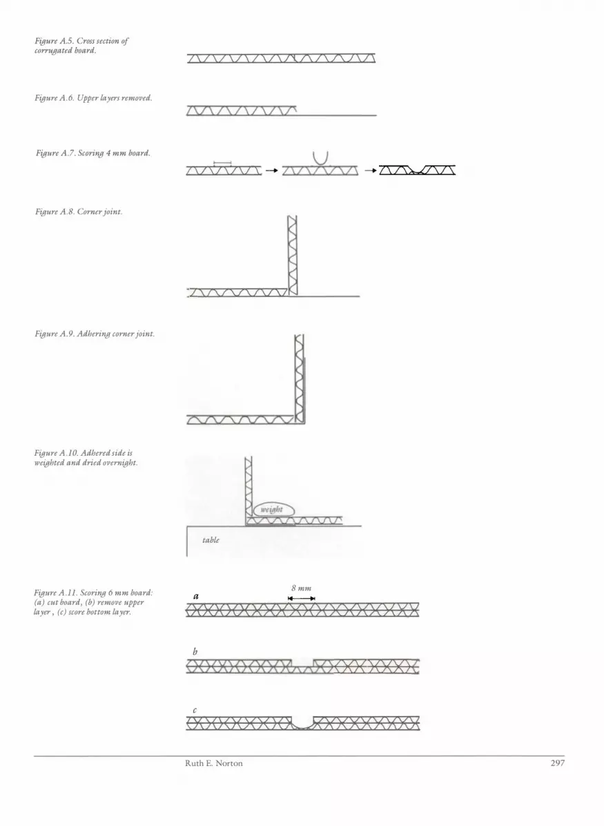
Figure A.s. Cross section of corrugated board.
Figure A. 6. Upper layers removed.
Figure A. 7. Scoring 4 mm board.
Figure A. 8. Corner joint.
Figure A. 9. Adhering corner joint.
Figure A.l O. Adhered side is weighted and dried overnight.
Figure A.ll. Scoring 6 mm board: (a) cut board, (b) remove upper layer , (c) score bottom layer.
/ \ / \ / \ / \ / \ / \ /'i 1\ / \ 1\ 2 \ / \
/\/S/\/\/S/S/'
u /\/\/\/\! \ -+ /\/\/\7\2\ -+ �
/ S7\7\7\/S7\7
7\1\1\ 7\1\/\1\/' table
8 mm a ___
O()()()Q( X)()()O()()()(><>"<)< Xl<
b
<>0000 O()06\1\iE) ()O<) O(X) ( c
O<>OO()()() (�gX)<X><><\><X>(
Ruth E. Norton 297

Figure A.12. Walls and base of folder.
Figure A.l3. Top hinged to folder.
Figure A.l4. Acid-Jree tissue wrapping for object. Flap 1 should have the same dimensions as the base.
298
length of object
�Ir
lid
flap 1
.... ...
... 3 " ." � � " � cm il � ;;:
hinge base and walls
base
Appendix 2: Construction of Storage Boxes

Appendix 3 Characteristics of Adhesives Ruth E. Norton
Classification of Adhesives by Setting Action
Wax
Thermoplastic resins
Suspended/dissolved in water
Dissolved in organic solvents
Synthetic resins suspended in water
Ruth E. Norton
Natural
Synthetic
Em ulsion and resin
fiiIn reactivation
Natural resins
Synthetic resins
Emulsions/colloidal dispersions
Carnauba
Beeswax
Paraffin
Microcrystalline
Polyethylene glycol
Poly( vinyl acetates)
Acrylates
Polyamides
Starch
Cellulose ethers
Protein
Shellac
Dammar
Rosin (colophony)
Lacquer
Acrylates
Vinyl acetates
Cellulose nitrate
Cyclohexanone
Vinyl butyrals
Vinyl alcohols
Soluble nylon
Polyurethane
Vinyl acetates
Animal glues
Epoxy
Polyester
Cyanoacrylates
Silicone rubber
299

Characteristics to Consider When Selecting Adhesives
1 . Thermoplastic vs. thermosetting
2 . Shrinkage upon setting
3 . Penetration
4. Aging properties
• discoloration
• shrinkage
• embrittlement
• cross-linkage
5 . Reversibility
6. Plasticizer
Technical Data
1 . Molecular weight (MW)
2. Particle size
3. Viscosity
4. Solubility
5 . pH
6. Glass transition temperature (T g)
7. Minimum ftlm formation temperature (MFT)
Where to Find Information
1 . Manufacturers' technical information data sheets
2. Suppliers' catalogues such as Conservation Materials Ltd. and Frank Joel Ltd.
3 . Books, articles, reports by conservators and conservation scientists
4. The Merck Index ( 1976, 9th Edition), Merck & Co. Inc . , Rahway,
New Jersey, U.S.A.
300 Appendix 3: Characteristics of Adhesives

Appendix 4
Table A.I. Fiber-reactive dyes used at the Canberra College of Advanced Education.
Dyeing Cellulosic Materials With Fiber-Reactive Dyes Ruth E. Norton
F iber-reactive dyes are often chosen for dyeing paper, cloth, cord, and plant mate
rials because they may be applied in cold water baths, have reasonable light fast
ness, and are easily reproducible. The dyes are formulated for use on cellulose and
some cellulose derivative fibers. They may also be used on silk fibers .
Hot water dyes are difficult to use on very fine papers like L-tissue and fine
Japanese paper, especially if these have low wet strength. Vat and disperse dyes in
general have better light fastness than fiber-reactive dyes, but the former use hot
water baths and the dyeing process of some is complicated enough to make color
reproducibility difficult. Selected fiber-reactive dyes have very good light fastness in
manufacturers' standard tests, and have proved fast under twenty months' exposure
to ambient laboratory light.
Bayer, Sandoz, ICI, Ciba-Geigy, and others manufacture ranges of fiber
reactive dyes. The choice of specific fiber-reactive dyes used at the Canberra College
of Advanced Education (CCAE) was based on manufacturers' light-fastness data
(Table A. l ) .
Color Dye Manufacturer
Red Levafix Rubine EFB Bayer Drimarene Rubinol K5BL Sandoz
Blue Levafix EFF A Bayer Yellow Levafix E2GL Bayer
Drimarene Yellow K2GL Sandoz Black Cibacron F2B Ciba-Geigy
Levafix Black ERL Bayer
Dyed Japanese Usamino paper (mulberry fiber) and unbleached cotton
muslin tested shortly after dyeing showed no pH change using cold extraction
determination of pH of dyed and undyed material; the pH of dyed raffia and panda
nus leaves increased toward neutral, primarily because of the predyeing scouring of
the leaves. All dyed material exhibited no crocking, and good fastness in water,
ethanol, acetone, and toluene.
Ruth E. Norton 301

A wide range of colors is available in fiber-reactive dyes . To determine the
particular dye or mix of dyes and the particular depth of shade necessary to produce
the desired color, a dye chart is necessary. Many manufacturers no longer supply dye
charts, and it may be necessary to make one's own. At the CCAE, a red, blue, and
yellow were chosen which, when two were mixed, created balanced purples, greens,
and oranges, and, when all three were mixed, created the broad range of brown
tones needed to match the colors found in many artifacts. Black was added to
deepen and "dirty" the colors . Using these, dye charts for cotton muslin and
Usamino paper were made for dye mix ratio (hue) and depth of shade.
Dyeing Paper
The paper is soaked in a bath of dye and salt solution for 45 minutes . Alkali solution
is then added and the paper is soaked for 70 to 1 1 0 minutes. The paper is rinsed in
running water for 4 hours and dried on a blotter. During this time, it is kept flat and
is transferred to and from the rinsebath on a Mylar sheet.
Materials
• tap, deionized, or distilled water
• salt: sodium chloride
• alkali: sodium carbonate (soda ash)
• dye
• dye bath tray: shallow, flat-bottom (essential) glass or plastic trays slightly
larger than the paper to be dyed
• hake brush: wide (at least 3 cm), flat, soft hair brush
Dye Calculations
The following factors must be determined:
• weight of paper
• depth of shade
• amount of dye
• volume of water
• amount of salt
• amount of alkali
• soaking time
The soaking times and the amounts of salt and alkali differ for particular
brands of fiber-reactive dyes. The amounts specified in the following instructions are
for Levafix, Drimarene, and Cibacron dyes. Check with the dye manufacturer or the
dye supplier for amounts recommended for other brands.
The discussion below uses the following example for purposes of illustra
tion: 0 . 5 g of paper dyed to a 4% depth of shade; the color is a hue of 2 parts red,
2 parts blue, and 6 parts yellow in a proportion of hue to black of 9: 1 ; a 0 . 1 % stock
solution of each dye is used.
302 Appendix 4: Dyeing Cellulosic Materials

Weight of Paper
Paper may be weighed or the basis weight of the paper may be used.
Amount of Dye
This is calculated from the depth of shade, weight of paper, and strength of stock
solution. Because of the small quantities of dye needed, it is best to prepare stock
solutions of the dyes from which the desired quantity of dye solution is taken.
(Stock solutions should be made up on the day they are to be used, ideally just
before they are needed. ) For example, 0 . 1% stock solution = 0 . 1 g dye per 1 00 rnl water.
The volume of stock solution needed is determined as follows:
depth of shade x 100
g paper 100 1
x % stock solution
total volume
For example, to dye 0 .5 g of paper to a 4% depth of shade using the 0 . 1 % stock
solution:
4 0.5 1 00 x x 100 1 0 . 1
20 ml stock solution
If mixes of red, blue, yellow, and black are to be used, a 0 . 1 % stock solution
of each is made, and the volume of each dye solution is calculated from their propor
tion in the mix.
To make a 4% depth of shade of hue 2R + 2B + 6Y in a proportion of hue
to black of9 : 1 , for example, it is calculated that 20 ml total of stock solution is
needed using the 0 . 1% stock solutions. For a hue to black proportion of9 : 1 , 1 8 ml
of hue and 2 ml of black are needed. The 1 8 ml of hue is made of2R, 2B, 6Y:
- 1 8 ml x 0.2 = 3.6 ml red
- 18 ml x 0.2 = 3 .6 ml blue
- 18 ml x 0.6 = 1 0.8 rnl yellow
Therefore, the total of20 ml stock solution is made from:
- 2 ml black stock solution
- 3 .6 ml red stock solution
- 3 .6 ml blue stock solution
- 1 0.8 ml yellow stock solution
Volume of Water
This is calculated based on the weight of paper using a liquor ratio of 70: 1 (70 ml
water per I g paper) . For 0 .5 g of paper, for example, 70 x 0 .5 = 35 ml water
needed. This is the total volume of water to be used in the bath. Of this, about one
quarter must be reserved to dissolve the alkali, and some is contributed by the stock
solution. Of the 35 ml total water needed, 10 ml is needed to dissolve the alkali,
leaving 25 rnl for the dye and salt solution. Since 20 ml of stock solution is needed,
5 ml of water is added to these 20 ml to make up the 25 ml of dye and salt solution.
The required weight of salt is added to the 25 rnl.
Ruth E. Norton 303

Amount of Salt
This is calculated based on the volume of water in the proportion of 50 g salt per
liter of water.
50 g x total ml water 1000 ml
g salt
In the example given, 35 ml total water is needed, therefore :
50 g _ 1000 ml x 35 ml
- 1 .75 g salt needed
Amount of Alkali
This is calculated based on the volume of water in the proportion of 20 g alkali per
liter of water:
20 g x total m! water 1000 ml
total g alkali needed
For 35 ml total water:
20 g x 35 ml 1 000 ml
Soaking Time
0.7 g alkali needed
The amount of time needed for soaking in the bath following addition of alkali is
based on the depth of shade :
< l % = 70 minutes
1 -5% "" 90 minutes
>5% = 1 1 0 minutes
Procedure
1 . Weigh out dye, salt, and alkali.
2 . Prepare dye stock solutions.
3 . Prepare dye and salt solution. Pipette the required volume of dye stock solution
into a beaker. Add water to reach the required amount. In the example, a total
of 35 ml of water is needed: 1 0 ml is reserved for dissolving the alkali, 20 ml of
stock solution is used, S ml of water must be added. Add salt to dye solution
and stir or swirl until dissolved.
4 . Pour dye and salt solution into a flat tray. Lay paper on the bath (start at one
corner and roll paper onto bath to avoid trapping air under paper) . Using a
hake brush, gently brush the surface of paper to fully wet it out and submerge it
in the bath. Alternatively, lay paper in tray, pour dye and salt solution over the
paper, and immediately brush over paper surface to fully wet out and brush out
air trapped under the paper.
304 Appendix 4: Dyeing Cellulosic Materials

5 . Paper soaks in the dye and salt solution bath for 4 5 minutes. Agitate by rocking
the solution back and forth over the paper. This should be done as frequently as
possible for the first 5 minutes, and at 5-minute intervals after that.
6. Add alkali. Before the 45 minutes are up, dissolve the alkali in the reserved
water (dissolves most readily if hot water is used) . At the appropriate time, pour
the alkali solution over the paper and immediately brush well over the paper sur
face to distribute and mix the alkali.
7. Paper soaks in the dye, salt, and alkali solution bath for 70, 90, or 1 10 minutes,
depending on the depth of shade desired. Agitate as described in step 5 .
8 . Rinse. Leaving the paper in the tray, place the tray in a large sink at a 45 ° angle
and gently run water from a hose over the paper until no more color runs out.
Transfer the paper to a photo tray or basin and leave in slowly running water for
4 hours.
9 . Transfer the paper from the rinse bath to a dry blotter using a sheet of 5 mil
Mylar.
For accurate duplication of color, exact measuring and timing is important.
The paper must be well brushed immediately upon addition of the dye and salt
solution and the alkali solution, and the baths must be agitated to produce even
dyeing of the paper. Thorough rinsing is necessary to remove all residual dye, salt,
and alkali .
Dyeing Cloth and Thread
Cloth should be scoured (boiled in soap and water for 30 minutes) or machine
washed in soap and hot water prior to dyeing. Fiber-reactive dyes are formulated for
dyeing cellulose and cellulose-derivative fibers-cotton, linen, jute, rayon, and so
on. Suppliers recommend that silk may be dyed with fiber-reactive dyes, but because
the alkali makes the silk harsh, the alkali proportion should be reduced and the rinse
should be followed by a final rinse in a mild acid solution.
The wetted cloth is soaked for 10 minutes in a bath of dye and water. Salt is
dissolved in water and added to the bath, 113 at a time, at 10-minute intervals. Fif
teen minutes after the last salt addition, the alkali is dissolved in water and added to
the bath, 1/3 at a time, at 1 0-minute intervals. After the last addition of alkali, the
cloth is soaked in the bath a further 50 to 90 minutes, depending on depth of
shade . The cloth is thoroughly rinsed and air dried.
The cloth should be lifted from the bath during the addition of the salt and
alkali, and should be gently agitated throughout the dyeing procedure, to avoid
uneven dyeing. Accurate measurement of materials and strict timing are important
to ensure accurate reproduction of color.
Materials
• tap, deionized, or distilled water
• salt: sodium chloride
• alkali: sodium carbonate (soda ash)
• dye
Ruth E. Norton 305
• cloth
• dye bath container: glass or plastic basin or jar
• stirring rod, plastic glove
Dyeing Calculations
Determine:
• depth of shade
• amount of dye
• volume of water
• amount of salt
• amount of alkali
• soaking time
The soaking times and the amounts of salt and alkali may differ for par
ticular brands of fiber-reactive dyes. The amounts specified in the following instruc
tions are for Levafix and Drimarene dyes. Check with the dye manufacturer or dye
supplier for amounts recommended for other brands of dyes.
Amount of Dye
This is calculated from the depth of shade and the weight of cloth.
depth of shade x 100
g cloth 1
= g dye needed
If the amount of dye needed is large enough to weigh accurately it may
simply be weighed out and used. If the amount of dye needed is smail, it is more
accurate to make stock solutions of each dye needed and measure the required
volume of stock solution. See discussion of stock solutions in instructions for dyeing
paper. The concentrations of stock solutions for cloth are often higher than those
for paper (for example, 0 .5% or 1 .0%).
Volume of Water
This is calculated on the weight of cloth using a liquor ratio of 30 : 1 (30 ml water
per I g cloth) . For example:
30 ml x 1 0 g cloth = 300 ml water needed
This is the total volume of water to be used in the bath. Of this, about 2/3
is used to dissolve the dye, about lj6 is reserved to dissolve the salt, and about lj6 is
reserved to dissolve the alkali. For example, if the total amount of water required is
300 ml, it would be used in the following proportions:
306
• 1 75 ml to dissolve the dye
· 75 ml to dissolve the salt
• 50 ml to dissolve the alkali
Appendix 4: Dyeing Cellulosic Materials

If stock solutions of dye are used, the volume of stock solution is included
in the amount of water used with the dye, as noted above . See notes on determining
the amount of dye and volume of water for dyeing paper.
Amount of Salt
This is calculated on the basis of the volume of water in the proportion of 50 g salt
per liter water.
50 g x ml total water 1000 ml
g salt
For example, if 300 ml total water is needed:
50 g _
1 000 ml x 300 ml water - 1 5 g salt
Amount of Alkali
This is calculated based on the volume of water in the proportion of 20 g alkali per
liter water.
20 g - x ml total water 1000 ml
g alkali
For example : 300 ml total water are needed.
20 g x 300 ml water 1000 ml
Soaking Time
6 g alkali
The time required for soaking in the bath following the last addition of alkali is
based on depth of shade :
< l % = 50 minutes
1-5% = 70 minutes
>5% = 90 minutes
Procedure
1 . Weigh out dye, salt, and alkali.
2 . Prepare dye solution by dissolving the dye powder in warm water, or by using
stock solutions and water.
3 . Wet cloth in tap water and wring out as much water as possible.
4. Immerse wetted cloth in dye solution for 10 minutes. Agitate continuously by
moving the cloth with gloved fingers or a stirring rod.
5 . Addition of salt. Before the above ten minutes are up, dissolve all the salt in the
required volume of hot water. At the appropriate time, lift the cloth above the
dye bath, pour in lf3 of the salt solution, mix well, and lower the cloth back into
the bath. Agitate continuously. Repeat twice at 10-minute intervals.
Ruth E. Norton 307
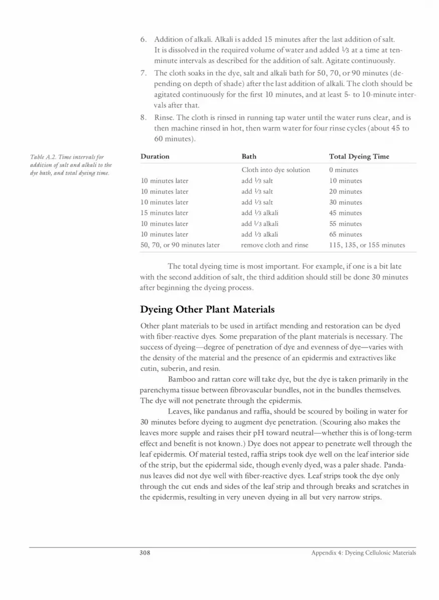
Table A.2. Time intervals for addition of salt and alkali to the dye bath, and total dyeing time.
6. Addition of alkali. Alkali i s added 15 minutes after the last addition of salt.
It is dissolved in the required volume of water and added 1/3 at a time at ten
minute intervals as described for the addition of salt. Agitate continuously.
7. The cloth soaks in the dye, salt and alkali bath for 50, 70, or 90 minutes (de
pending on depth of shade) after the last addition of alkali. The cloth should be
agitated continuously for the first 10 minutes, and at least 5- to 1 0-minute inter
vals after that.
8 . Rinse. The cloth is rinsed in running tap water until the water runs clear, and is
then machine rinsed in hot, then warm water for four rinse cycles (about 45 to
60 minutes) .
Duration Bath Total Dyeing Time
Cloth into dye solution o minutes 10 minutes later add 1/3 salt 1 0 minutes 10 minutes later add lf3 salt 20 minutes 1 0 minutes later add lf3 salt 30 minutes 1 5 minutes later add lf3 alkali 45 minutes 10 minutes later add lf3 alkali 55 minutes 10 minutes later add lf3 alkali 65 minutes 50, 70, or 90 minutes later remove cloth and rinse l l 5, 1 35, or 1 5 5 minutes
The total dyeing time is most important. For example, if one is a bit late
with the second addition of salt, the third addition should still be done 30 minutes
after beginning the dyeing process .
Dyeing Other Plant Materials
Other plant materials to be used in artifact mending and restoration can be dyed
with fiber-reactive dyes. Some preparation of the plant materials is necessary. The
success of dyeing-degree of penetration of dye and evenness of dye-varies with
the density of the material and the presence of an epidermis and extractives like
cutin, suberin, and resin.
Bamboo and rattan core will take dye, but the dye is taken primarily in the
parenchyma tissue between fibrovascular bundles, not in the bundles themselves.
The dye will not penetrate through the epidermis.
Leaves, like pandanus and raffia, should be scoured by boiling in water for
30 minutes before dyeing to augment dye penetration. (Scouring also makes the
leaves more supple and raises their pH toward neutral-whether this is oflong-term
effect and benefit is not known. ) Dye does not appear to penetrate well through the
leaf epidermis. Of material tested, raffia strips took dye well on the leaf interior side
of the strip, but the epidermal side, though evenly dyed, was a paler shade. Panda
nus leaves did not dye well with fiber-reactive dyes. Leaf strips took the dye only
through the cut ends and sides of the leaf strip and through breaks and scratches in
the epidermis, resulting in very uneven dyeing in all but very narrow strips.
308 Appendix 4: Dyeing Cellulosic Materials

absorption
adsorption
aerenchyma
amorphous
amphiphloic siphonostele
amphivasal vascular bundle
angstrom
annual ring
axillary bud
bark
bast fiber
birefringence
bordered pit
cambium
carbohydrate
Glossary
Penetration of a substance into the structure of another, such as through capillary
action or as radiant energy passing through a material.
Chemical condensation of gasses, liquids, or dissolved substances on surfaces.
Parenchyma tissue with large intercellular spaces ftlled with air.
Without definite crystalline form or structure; loosely or randomly structured at the
molecular level.
Tube-like stele with phloem both external and internal to the xylem.
Concentric vascular bundle in which the xylem surrounds the phloem.
Unit of length, used in discussing light waves, equal to one tenth of a nanometer,
one ten-thousandth of a micron, or one ten-billionth of a meter.
Growth ring in secondary xylem formed in one growth period.
Bud in the axil of a leaf.
Nontechnical term for all the tissues outside the vascular cambium.
Any extra-xylary fiber such as a phloem fiber.
Light-refracting ability of crystalline materials.
Pit in cell walls of coniferous tracheids in which the secondary wall overarches the
pit membrane.
Embryonic tissue that gives rise to secondary tissue .
Molecules containing only hydrogen, oxygen, and carbon atoms in various combina
tions. A carbohydrate that cannot be hydrolyzed to simpler compounds is called a
monosaccharide . A carbohydrate that can be hydrolyzed into two monosaccharide
molecules is called a disaccharide. A carbohydrate that can be hydrolyzed into many
monosaccharide molecules is called a polysaccharide .
Glossary 309

carbonylgroup (C=O)
carboxylgroup (COOH)
cellulose
chain reaction
chlorenchyma
chromophore
collagen
collenchyma
companion cell
compression strength
coniferous
cork
cortex
covalent bond
crossfield pitting
cuticle
cutin
dicotyledon
dictyostele
diffuse porous
Functional group that largely determines the acidity of many aldehydes and
ketones and their susceptibility to nucleophilic adclition.
Functional group made up of a carbonyl group (C=O) and a hydroxyl group (OR)
giving carboxylic acids their characteristic properties such as polarity and hydrogen
bonding capability.
Polysaccharide polymer that is the main structural chemical in the plant cell wall .
Self-sustaining molecular process in which the products of a reaction directly
contribute to the propagation of the process.
Parenchyma tissue made up of cells which contain chloroplasts.
Chemical group in a molecule that reflects and absorbs light in the visual spectra,
thereby producing color in a compound.
Basic fibrous protein molecule located in the fibers of the dermis of skin and in
sinew and other structural tissues in animals.
Supporting primary tissue composed of cells with unevenly thickened primary walls
rich in hemicellulose .
Parenchyma cell associated with a sieve tube member.
Stress required to produce failure in a material when pressing or squeezing to
reduce volume.
Refering to cone-bearing trees, usually with needle-like leaves, such as pine, spruce,
cedar, and others.
Nontechnical term for outer bark (see phellem cells); the cells are waterproofed with
suberin.
Primary ground tissue which fills areas between the epidermis and the vascular tissue .
Bond formed by the sharing of a pair of outer valence electrons by two atoms.
Pits on raclial walls that join ray parenchyma cells and longitudinal tracheids or
vessels.
Layer of cutin on the outer walls of epidermal cells.
Complex waxy substance excreted on the outer surface of epidermal cells.
Plant with two seed leaves in the embryonic seed, such as hardwood trees, linen,
hemp, and others.
Stele in which the vascular system is dissected into anastomosing strands with the
phloem surrounding the xylem.
A characteristic of hardwood xylem in which the vessels are evenly distributed
throughout the annual ring.
3 1 0 Glossary
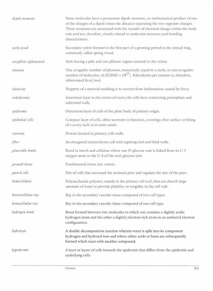
dipole moment
early lVood
ectophloic siphonostele
einstein
elasticity
endodermis
epidermis
epithelial cells
extensin
fiber
glucosidic bonds
ground tissue
guard cells
hemicellulose
heterocellular ray
homocellular ray
hydrogen bond
hydrolysis
hypodermis
Some molecules have a permanent dipole moment, or mathematical product of one
of the charges of a dipole times the distance separating the two opposite charges.
These moments are associated with the transfer of electrical charge within the mole
cule and are, therefore, closely related to molecular structure and bonding
characteristics.
Secondary xylem formed in the first part of a growing period in the annual ring,
commonly called spring wood.
Stele having a pith and one phloem region external to the xylem.
One avogadro number of photons, numerically equal to a mole, or one avogadro
number of molecules, (6.022045 x 1 023
) . Kilocalories per einstein is, therefore,
abbreviated Kcal/mol.
Property of a material enabling it to recover from deformation caused by force.
Innermost layer in the cortex of roots; the cells have connecting protoplasm and
suberized walls.
Outermost layer of cells of the plant body of primary origin.
Compact layer of cells, often secretory in function, covering a free surface or lining
of a cavity such as in resin canals.
Protein located in primary cells walls.
An elongated sclerenchyma cell with tapering end and thick walls.
Bond in starch and cellulose where one D-glucose unit is linked from its C-1
oxygen atom to the C-4 of the next glucose unit.
Fundamental tissue (see cortex) .
Pair of cells that surround the stomatal pore and regulate the size of the pore.
Polysaccharide polymer, mainly in the primary cell wall, that can absorb large
amounts of water to provide pliability or turgidity in the cell wall.
Ray in the secondary vascular tissue composed of two cell types.
Ray in the secondary vascular tissue composed of one cell type.
Bond formed between two molecules in which one contains a slightly acidic
hydrogen atom and the other a slightly electron-rich atom in an unshared electron
configuration.
A double decomposition reaction wherein water is split into its component
hydrogen and hydroxyl ions and where either acids or bases are subsequently
formed which react with another compound.
A layer or layers of cells beneath the epidermis that differs from the epidermis and
underlying cells.
Glossary 3 1 1

idioblast
ionic bond
lacuna
late wood
lenticel
lignin
lumen
meristem
mesophyll
metaxylem
middle lamella
moisture regain
monocotyledon
multiseriate rays
nanometer
parenchyma
pectic substances
perforation plate
peri cycle
periderm
Cell that differs markedly in shape from the majority of cells in generally uniform
tissue.
Bond that occurs when outer valence electrons are transferred between two atoms.
Air space or empty cavity formed by the destruction of specific cells in a tissue, as in
aerenchyma or protoxylem.
Secondary xylem formed in the latter part of a growing period in the annual ring,
commonly called summer wood.
Conspicuous apertures on stems, usually over pre-existing stomates.
Amorphous organic mixture of phenolic-like chemicals deposited between the
cellulose fibrils in the cell wall.
Central cavity of a cell.
Embryonic tissue that gives rise to primary tissues.
Photosynthetic parenchyma of a leaf blade located between the upper and lower
epidermis.
Primary xylem vessels that form after the protoxylem.
Layer of pectin and lignin-rich substances that cement the primary walls of adjacent
cells.
The ability of a material to adsorb water molecules, measured as a change in weight
from the oven-dry state, at a specific pressure, temperature, and relative humidity.
Plant with one seed leaf in the embryonic seed, such as grasses, palms, lilies, rushes,
and reeds.
Secondary vascular tissue tays wider than two cells, as seen in tangential view.
U nit of measurement, especially of light waves, equal to ten angstroms or one
billionth of a meter.
Tissue composed of undifferentiated, irregular-shaped cells each with a nucleated
protoplast, that commonly stores metabolic products such as starch or crystals.
Group of complex carbohydrates, occurring mainly in the primary cell walls and
middle lamella, that can absorb large amounts of water.
Part of the end wall of the vessel member cell, which is perforated and joins to other
members to make a continuous vessel tube.
Part of the ground tissue of the stele of roots, located between the phloem and the
endodermis.
Protective complex secondary tissue composed of phellem, cork cambium, and phel
loderm cells, that replaces the epidermis in stems and roots; commonly called bark.
3 1 2 Glossary

phellem
phelloderm
phellogen
phloem
phytolith
plasticity
primary tissue
procumbent ray cells
protostele
protoxylem
ray parenchyma
reticulate
rhizoid
rhizome
rhytidome
ring-porous
sclariform
sclereid
sclerenchyma fiber
sclerenchyma sheath
secondary tissue
shear strength
Outer protective secondary tissue of stems and roots, composed of nonliving cells
with suberized cell walls, formed from the phellogen (cork cambium) ; commonly
called cork.
Embryonic cells that give rise to the tissue of the periderm.
Cork cambium giving rise to phellum and phelloderm.
Principal photosynthate-conducting tissue of vascular plants.
Needle-shaped crystal located in parenchyma cells.
The ability to retain a shape attained through deformation from an applied stress.
Plant tissue derived from the meristems of the seed embryo.
Secondary vascular tissue ray cells that, in radial view, have the longest axis in the
radial direction.
The simplest type of stele containing a solid column of vascular tissue, with the
phloem outside the xylem.
First-formed vessels of the primary xylem.
Parenchyma cell that makes up the radial rays in secondary vascular tissue .
Netlike .
A dermal protrusion on the stem, rootlike in appearance but not function.
Underground stem.
Term for the outer bark, used to designate old layers of periderm.
A characteristic of hardwood xylem in which the vessels form a well-defined ring at
the beginning of the annual ring.
Ladderlike.
Sclerenchyma cell, varied in shape, not elongate, with thick, lignified, laminated,
pitted walls.
Elongate cell with thick, lignified, pitted cell wall.
Group of sclerenchyma cells that may partially or completely surround a vascular
bundle to give it strength.
Tissue produced by the activity of the vascular cambium and the phellogen (cork
cambium).
Stress required to produce failure in a material when impressed perpendicularly
upon the cross section of the material.
Glossary 3 1 3

sieve element
sieve tube
silica cells
stele
stellate
stoma (stomate)
stomatal complex
strain
stress
suberin
subsidiary cell
tensile strength
tracheid
trichome
ultimate fibers
uniseriate ray
vapor pressure
vascular bundle
vessel
vessel member
xylem
Individual cell of the sieve tube, commonly called sieve cell or sieve tube member,
that is involved in longitudinal conduction of food material in the phloem.
Series of sieve elements connected end to end, and interconnected through sieve
plates, involved in longitudinal conduction of food materials in the phloem.
Cells filled with silica bodies, usually in the epidermis of grasses.
Column of the plant body comprising the vascular and associated ground tissues.
Star-shaped.
Opening in the epidermis of leaves and stems bordered by two guard cells.
Guard cells and associated subsidiary epidermal cells that work together for the
opening and closing of the stoma.
Deformation of a material resulting from stress, measured by change in the dimen
sion in which the deformation occurred.
Force producing, or tending to produce, deformation in a material .
Fatty substance, impermeable to water, deposited in the cell wall of cork and
endodermal cells.
Epidermal cell associated with guard cells in the stomatal complex.
Longitudinal stress required to produce failure in a material .
Tracheary element of the primary or secondary xylem that has tapered ends and
does not have perforations joining it end to end with other tracheids.
An epidermal cell that is unicellular or multicellular and may take the shape of a hair
or scale and may be glandular.
Individual cells that have been separated from their original configuration within the
structure of a plant.
Secondary vascular tissue rays that are a single cell in width as seen in tangential view.
Pressure exerted when a liquid is in equilibrium with its own vapor, which is a
function of the substance and of the temperature .
Strandlike part of the vascular system composed of xylem, phloem and, if present,
associated sclerenchyma sheath.
Tube-like series of vessel member cells used for water transport in xylem of dicots,
monocots, and some lower plants.
One of the cells that make up a vessel in the xylem of dicots, monocots, and some
lower plants.
Principal water-conducting and nutrient-carrying tissue in vascular plants.
3 14 Glossary

Index
A *
Abaca, 120- 121
See also Manila, Hemp, Musa sp. identification of fibers, 45
Abrus sp., 125
Acacia sp., 1 0 1 - 1 02
Acer sp. secondary phloem, 70
See also Maple Achiote seed, 1 32
Acid hydrolysis, 22, 165-1 66
Acryloid, 258, 260, 269
Adhesives, 198, 204, 250-257, 259
See also Starch paste, specific chemical and brand names
characteristics of, 299
reactivated film, 259-262
removal of, 228-229
Adiantum sp., stem, 60
Aechmea sp., 124
Aerenchyma, 4, 9, 60, 64
Mrica, 46, 83, 1 03, 1 1 5 , 128-129, 1 3 1 -
1 32, 163
Agavaceae processing, 122
vascular bundle, 1 0
Agave sp., 1 3, 120, 122
See also Sisal composition of fibers, 123
description, 46
fiber extraction, 86
fibers, 122
harvesting, 122
identification of leaf fibers, 46
use in artifacts, 123
Aguilaria sp. , 1 02
Alahe<e, 1 3 1
Alder, 73
Index
Algae, 2, 35
Ammonia, 1 5 3
Amorphous regions, 1 50, 1 59
birefringence of, 2 1
Ananas sp., 120, 124
See also Pineapple Angiosperms, 2
sieve elements in, 1 1
Aniline blue, 32, 53
directions for use, 35
staining of protein, 52
Apocynum sp. , ll , 5 0
See also Indian hemp compared to Asclepias, 5 1
Aristolochia sp. , 26
Artemisia sp. , 66, 70
Artocarpus sp. , 103
Arum sp. , 1 3 1
Asclepias sp., 4 1 , 5 0
See also Milkweed compared to Apocynum, 5 1
identification of fibers, 40-41
Asia, 84, 103, 248
Australia, 99, 1 00-102 1 16 1 18 141 , , , , 236, 244, 261
B
Bacteria, 68, 1 79-180
deterioration of cellulose, 22
utilization of pectic substances 25
Baleen, 52-53, 56 '
Balsa wood, 250, 268
Bamboo, 84, 88, 99, 1 04-105 1 1 3 1 1 7
208, 247-249, 255 " ,
anatomy, 105
branch sheath, 119
cleaning, 224
3 1 5
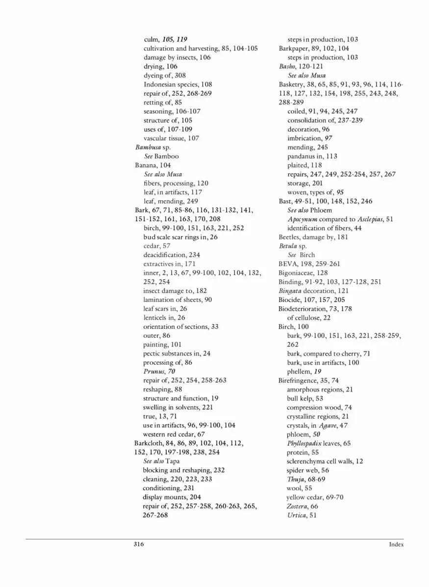
culm, 105, 119
cultivation and harvesting, 85 , 1 04-105 damage by insects, 1 06 drying, 106 dyeing of, 308 Indonesian species, 1 08 repair of, 252, 268-269 retting of, 85 seasoning, 106-107 structure of, 105 uses of, 1 07- 109 vascular tissue, 1 07
Bambusa sp. See Bamboo
Banana, 1 04 See also Musa
fibers, processing, 120 leaf, in artifacts, 1 17 leaf, mending, 249
Bark, 67, 7 1 , 85-86, 1 16, 1 3 1 - 1 32, 141 , 1 5 1 - 1 52 , 1 6 1 , 163, 1 70, 208
birch, 99- 1 00, 1 5 1 , 163, 221 , 252 bud scale scar rings in, 26 cedar, 57 deacidification, 234 extractives in, 171 inner, 2, 1 3, 67, 99-1 00, 102 , 1 04, 1 32 , 252, 254 insect damage to, 182 lamination of sheets, 90 leaf scars in, 26 lenticels in, 26 orientation of sections, 33 outer, 86 painting, 101 pectic substances in, 24 processing of, 86 Prunus, 70
repair of, 252, 254, 258-263 reshaping, 88 structure and function, 19 swelling in solvents, 221 true, 1 3, 71 use in artifacts, 96, 99- 100, 1 04 western red cedar, 67
Barkcloth, 84, 86, 89, 102, 104, 1 12 , 1 52 , 1 70, 197-198 , 238, 254
See also Tapa blocking and reshaping, 232 cleaning, 220, 223, 233 conditioning, 231 display mounts, 204 repair of, 252, 257-258, 260-263, 265, 267-268
3 1 6
steps i n production, 1 0 3 Barkpaper, 89, 1 02, 1 04
steps in production, 1 03 Basho, 120- 1 2 1
See also Musa
Basketry, 38, 65, 85, 9 1 , 93, 96, 1 14, 1 16-1 1 8 , 127, 1 32, 1 54, 198, 255, 243, 248, 288-289
coiled, 9 1 , 94, 245, 247 consolidation of, 237-239 decoration, 96 imbrication, 97
mending, 245 pandanus in, 1 1 3 plaited, 1 1 8 repairs, 247, 249, 252-254, 257, 267 storage, 201 woven, types of, 95
Bast, 49- 5 1 , 100, 148, 1 52, 246 See also Phloem ApocYllum compared to Asclepias, 5 1 identification of fibers, 44
Beetles, damage by, 1 8 1 Betula sp.
See Birch BEVA, 198, 259-261 Bigoniaceae, 128 Binding, 9 1 -92, 103, 127-128, 251 Bingata decoration, 1 2 1 Biocide, 107, 1 57, 205 Biodeterioration, 73, 1 78
of cellulose, 22 Birch, 1 00
bark, 99-1 00, 1 5 1 , 163, 221 , 258-259, 262 bark, compared to cherry, 71 bark, use in artifacts, 1 00 phellem, 1 9
Birefringence, 35, 74 amorphous regions, 21 bull kelp, 53 compression wood, 74 crystalline regions, 21 crystals, in Agave, 47 phloem, SO Phyllospadix leaves, 65 protein, 55 sclerenchyma cell walls, 12 spider web, 56 Thuja, 68-69 wool, 55 yellow cedar, 69-70 Zostera, 66 Urtica, 5 1
Index

Bitter cherry See Prunus
Bixa sp., 1 32 BJK, 268 Black cottonwood, 42 Boehmeria sp.
See also Ramie identification of fibers, 5 1 use in artifacts, 1 03
Borassus sp., 1 1 6 See also Palm
Borneo, 1 10 Braiding, 148 Branch wood, 17-18, 1 1 7, 1 19
identification of, 75 orientation of sections, 33
Breadfruit, use in artifacts, 103 Bromeliaceae, 120
processing of fibers, 124 Bromophenol blue, 32, 184
directions for use, 36 Broussonetia sp. , use in artifacts, 103 Brown rot, 22, 107, 180 Bryophytes, 2 Bud scale scar rings, 26 Bull kelp, 57
See also Nereocystis
identification of, 5 3 structure of, 61
Bulrush, 9, 57
c
See also Scirpus
identification of, 58
Calabash, 128 See also Gourd
Calcium oxalate crystal See Crystals, calcium oxalate
Cambium, 3 cork, 13 - 14, 19 vascular, 13 , 18
Candle nut, 126 Cannabis sp., 1 1
See also Hemp identification of fibers, 49
Canoe, construction of, 101 Camula fiber
See Agave
Carbon hydroxyl groups, 147 Carex sp. , leaf, 64 Cattail, 39, 57, 63
See also Typha
Index
ethnographic use of fibers, 44 identification of fibers, 39, 42
Cayenne fiber, 124 Cedar, 14
bark, 57, 67, 100, 262-263 red, 38 western red, 1 8 , 67- 68, 73, 75, 76, 1 5 1 withes, 73 yellow, 69
Ceiba sp. See also Kapok identification of fibers, 40, 42-43
Cell, 3, 5 1 , 148, 155 , 165 aerenchyma, 9 basic types of, 7 chlorenchyma, 5 collenchyma, 12 companion, 4, 9, 18 cork, 71 effects of deacidification, 233 embryonic, 3 endodermal, 4 endosperm, 125 epidermal, 4-5, 8, 25, 59- 60, 66, 126 epidermal, staining of, 36 epithelial, 16, 74-75 glandular, 4, 8 guard, 59 hair, 8-9 hypodermal, 4-5 late, 180 metaxylem, 10 parenchyma, 9, 1 5 , 18- 19, 67-68, 74, 76, 125, 128, 180 phellem, 19, 70-71 phelloderm, 14, 19 phloem, see Phloem protoxylem, 10 ray parenchyma, 14, 16 sclerenchyma
see Sclerenchyma shrinkage, 201 sieve, 67-69 stellate, 59- 60 stomatal, 4 subsidiary, 8 tannin, see Tannin trichome, 4 ultimate, 49-50 xylem, see Xylem
Cell wall, chemistry and structure of, 39, 1 50, 1 6 1 , 1 70, 186, 240
collapse of microcapillaries, 150 deterioration of, 186
3 1 7

function of pectin in, 24 protein in, 25 response to humiclity, 230 staining of, 37 suberin in, 25
Cellulose, 5 1 , 87, 146, 150-1 5 1 , 1 57, 1 59, 161-1 62, 1 64, 1 74, 1 80, 1 82 , 220, 257, 299
amorphous regions, 148 cellulose chains, 149 chemical deterioration of, 1 67 chemical structure of, 20 content of sisal, 123 crystalline regions, 148 damage by fungi, 180 deaciclification, 233 depolymerization of, 22 deposition in compression wood, 74 dyeing of, 301 effect of humectants, 240 hydration of, 2 1 microfibrils, 49 photodegradation of, 157 polymers, 147, 158 swelling, 230 thermal degradation of, 164 waterlogged, 21
Cellulose acetate, 262 Cellulose ether, 238, 2 5 1 , 253, 255-257, 29 1 Cellulose nitrate, 228, 2 5 1 , 267 Central America, 46, 1 03, 122- 124, 128, 1 32 Chamaecyparis sp. , 69
Chemical deterioration, 165-167 Cherry bark, 71 , 100
See also Prunus
China, 128 China grass
See Ramie, Boehmeria
Chlorenchyma, 4-5, 60
Scirpus, 59
Chromatograms, 185 Cleaning of artifacts, 2 15 -225
solvents, 2 19-220, 222-225 tools, 2 1 8 vacuuming, 2 1 6-217
Coconut, 1 15 , 145, 237 See also Cocos, Palm fiber, 261 fiber, cordage, 237, 246 fiber extraction, 86 sheil, 126-127, 1 30, 252
Cocos sp., 1 1 5 , 1 17- 1 18
3 1 8
See also Palm fruit, use in artifacts, 126- 127
Coiling, 92 types of, 94
Coir, 127 See also Cocos, Coconut
Coix sp. , 125 Coilagen, 25, 54-55 Collenchyma, 4-5
clistribution, 12 pectic substances in, 24 structure and function of, 12
Companion cell, 1 8 Conclitioning of artifacts, 229, 230 Congo, 125 Conservation
cleaning, 2 1 5-216 consolidation, 236-238 deaciclification, 234 documentation of treatment, 2 10-2 1 3 examination, 209 in the field, 208 reversibility, 209 surveys, 200 treatment procedures, 208
Consolidation, 196, 235-238 , 259 Construction techniques, 87
cutting, 87 drilling, 88 edging, 97 interworked elements, 91 joins, 89 knotting, 92 looping, 93 molcling, 88 wrapping, 93
Cook Islands, 1 14 Coprosma sp., 124 Corchorus sp.
See also Jute identification of fibers, 49
Cordage, 38, 46, 6 1 , 64, 83, 89, 99, 102-104, 1 16, 120, 123, 127, 148 , 1 6 1 , 223, 243, 249
cleaning, 233 coconut fibe� 127, 237 consolidation of, 237-238 identification of protein material, 53 insect damage to, 181 knotted, 91 Manila hemp, 45 mencling, 244, 246
plaited, 90 production of, 90
Index

repair of, 253, 260-262 Scirpus, 59
spruce root, 74 spun, 102 - 1 03 use of secondary phloem, 67 Yucca, 62
Cordyline sp. , 1 30 Cork cells, 19
See also Cell, phellem in birch, 19
in cherry, 71 Cork cambium, 1 3-14, 19 Corn,
See Zea
Corrugated board, 203, 293-298 Cortex, 4-5, 61
bullkelp, 61 extractives in, 171 hair, 54 in roots, 7 secondary, 14 Yucca, 62
Corypha sp., 1 16 See also Palm
Cotton, 126, 207, 2 1 3, 224-225 , 305 See also Gossypium
cleaning of fibers, 223 hemicellulose in, 23 identification of fibers, 40 orientation of sections, 32 pectic substances in, 24 staining of samples, 32 swelling of, 21
Cotton grass, 39 See also Eriophorium
identification of fibers 39 42 Crystalline, 146, 148, 15�, 1�3, 1 67 Crystalline regions, 20, 149, 1 59
birefringence of, 2 1 Crystals, 47
calcium oxalate, 68-69 druses, 5 1 in Agave, 48 in hemp, 49 in Urtica, 50
Cucurbitaceae, 128 vascular bundles in, 6
Culm, bamboo, 107, 109, 119
Cushioning artifacts, 207 Cuticle, staining samples, 32 Cutin, 8, 85, 1 6 1 , 165, 184, 226
and dye, 308 chemical deterioration of, 171 chemical structure of, 25
Index
solubility of, 25, 221 staining samples, 36
Cyathea sp. , 1 1 1 Cyperaceae, 59, 1 1 0 Cyperus sp., 1 1 1
D
Deacidification, 195, 233-234 Dendrocalamus sp., 1 07
See also Bamboo Depolymerization of cellulose, 22 Deterioration
biological, 178- 1 8 1 chemical, 165-174 mechanical, 175-177 physical, 146- 164
Dichromatic stain, 37 Dicksonia sp. , 1 1 1 Dicot
fiber tracheids, 15 leaf structure, 7 leaves, in artifacts, 1 12 - 1 1 3 sclerenchyma fibers in, 12 secondary phloem, 67 steles in, 5 stem, identification of fibers, 49 vascular bundles in, 6
Dictyostele, 5 Dinoderus minutus, 1 06 Display mounts, 204
See also Mounting of artifacts Documentation, 2 10-21 3 Douglas fir, 74 Dry cleaning
See Solvents Drying of plant materials 85 Dunegrass
'
See Elymus
Dutchman's pipe, lenticels in, 26 Dye, 87, 109, 1 14-1 16, 120, 160, 222, 233, 267, 302
.
dyeing bark, 103 dyeing coconut fiber, 127 dyeing pandanus, 1 1 3 dyeing Phormium fibers 124 dyeing plant materials ;08 dyeing techniques, 98' fiber-reactive, use of, 301 -308 from palm root, 121 Musa, 122 photooxidation of, 1 60 textiles, 1 2 1
3 1 9

E
Easter Island, 1 1 1 , 1 18 , 238 Eel grass, 66
see also Zostera
Elaeocarpus sp. , 124 Elderberry bush
See Sambucus
Elm, 73 Elymus sp. , 60 Endocarp, 126-127 Endodermis, 4, 7
in vascular bundle, 125 Yucca, 62
Endosperm, 125 Epidermal cell, 8 , 126
cutin in, 25 Musa, 47 Scirpus, 59
solubility of, 221 staining of, 184 staining samples, 36
Epidermis, 4, 6, 51, 53, 227, 248, 256, 263
bullkelp, 6 1 Carex leaf, 64 dyeing, 308 Equisetum, 62 fern, 60 fiber extraction, 86 Musa, 1 18, 120 Nereocystis, 60 penetration by consolidants, 239 root, 7 structure of, 8 Xerophyllum, 65
Epilobium sp. See also Fireweed identification of fibers, 40, 42-43 orientation of sections, 32 staining of samples, 32
Epithelial cell, 16 Picea, 74
thick- and thin-walled, 16 Epoxy, 2 19, 299
removal of, 229 Equisetum sp. , 62
See also Horsetail Eriophorium sp.
See also Cotton grass identification of fibers, 39, 42-43 orientation of sections, 32 staining of samples, 32
320
Eskimo, 249 Ethylene oxide, 1 73 Eucalyptus sp. , 14, 19
See also Stringybark use in artifacts, 1 0 1
Exocarp, 126-127 Extensin, 25 Extractives, 85 , 105, 141 , 1 5 1 , 1 56, 1 7 1 , 1 8 5
F
False embroidery See Imbrication
Fan palm, use in artifacts, 1 16 Fat, staining samples, 36 Feather, staining samples, 35 Fern, 99, 1 3 1 , 237
steles in, 5 structure of, 61 tree fern trunk, 111 vascular bundles in, 6 vascular tissue, I I I
Ferric chloride, 32 Ferric sulfate, 185
directions for use, 36 staining of bark, 71 staining of secondary phloem, 67
Fiber, 5 1 , 72, 86, 89, 102 , 1 2 1 , 145, 148, 1 5 1 - 1 52, 1 54-155 , 1 6 1 , 260, 301 , 303, 305, 307
Agave, 122 ba.st, 5 1 , 148 bundles, 55 coconut, 127 extraction, 86, 122, 124 felted sheets, 89 identification of, 38 monocot leaf, 1 19 Musa, processing, 120 orientation of sections, 34 phloem, 44, 1 19 phloem, identification of, 49 Phormium, 123 pineapple, 13 protein, 52, 55 relative tensile strength, 120 sclerenchyma, 1 1 -12, 18 , 45-46, 102 , 1 19 secondary phloem, 67 sheath, 125 sheath, Ananas, 124 ultimate, 1 52, 186 xylem, 1 19
Index

Fiber tracheid, 15 See also Tracheid, fiber
Fibril cellulose, 148 protein material, 53
Ficus sp., use in artifacts, 103 Field conservation, 208 Fig, 1 1 3, 258
use in artifacts, 103 Fiji, 1 1 3-1 14, 258 Fireweed
See also Epilobium
ethnographic use of fibers, 44 identification of fibers, 40, 42-43
Flax See also Linum, Linen identification of fibers, 49 pectic substances in, 25
Flexibility, restoration of, 239 Flower hair, identification of, 39 Foam, 206, 250
use in repairs, 269 Foam supports, 203 Formosa, 125, 1 30 Freycinetia sp. , 1 30, 1 32 Fruit, 25 , 127
anatomy, 126 fiber, uses of, 125 hair, identification of, 39
Fumigation, 1 10, 1 73 Fungi, 2, 85 , 107, 1 79-180, 183-184
deterioration of cellulose, 22 in bark, 71 staining, 184 staining samples, 35 utilization of pectic substances, 25
G
Gas chromatography, 1 82 Giant sagebrush
See Artemisia
Glandular tissue, 54 Glucose, 147 Glue, 35, 1 52 , 218 , 249, 299
removal of� 228 Glycerine, 238 Glycerol, 172 , 240 Gossypium sp.
See also Cotton identification of fibers, 40-41
Gourd, 84, 88, 246, 252 consolidation of, 236
Index
cultivation and harvesting, 129 decoration of, 1 3 1 repair of, 268 retting of, 86 uses of, 128, 130
Grass China, 5 1 cotton, 39 leaf epidermis, 8
Growth ring compared in trunk, branch, and root, 17 birch bark, 71 hardwood, 16
Prunus, 70
Thuja, 76
wood, 1 8 , 76 Guard cells, 8 Gunminggu, 101 Gut, identification of, 54 Gymnosperms, 2
sieve elements in, 1 1 steles in, S vascular bundles in, 6 use in artifacts, 1 1 3
H
Hair, 54, 1 84, 244 bamboo, 1 19 identification of, 53 seed, 42, 126 staining samples, 35, 52 structure of, 54 use in artifacts, 102
Halogens, 173 Hardwood, 2 , 180
bud scale scar rings in, 26 compared to softwood, 16 identification of characteristics, 72 lignin in, 22 rays 17
secondary phloem, 18 , 67 secondary tissue, 13 tracheary elements, 1 5
Hau, 1 32 Hawaii, 1 1 1 , 1 17-1 19, 128-1 32, 145, 233, 238, 246 Heartwood, 14 Hemicellulose, 20, 148, 1 5 0- 1 5 1 , 1 56-1 59, 1 6 1 - 1 62, 167-168, 1 70, 185, 220-221
and lignin, 22
321

chemical deterioration of, 1 67-168 chemical structure of, 24 content in sisal, 123 effect of humectants, 240 function of, 23 hydration of, 24 in collenchyma, 12 in hardwood tracheids, 15 oxidation of, 162 photodegradation of, 1 59 swelling, 230 table of, 1 69 thermal degradation of, 1 64
Hemp, 2, 12 See also Cannabis, Musa
identification of fibers, 49 Indian, 6, 44 Indian, identification of fibers, 50- 5 1 Manila, 4 5 , 1 2 0 pectic substances in, 2 5 ultimates, 50
Henequen, 120, 122 See also Agave
Hibiscus sp. , 103, 1 32 , 252 bark, 260
Hide identification of, 53 staining of, 52
Hilum, 127 Holei, 1 3 1
Horn, identification of, 5 6 Horsetail , 61 -62 Humectants, 240-241 Humidity, 2 0 1 , 208 Hydration of cellulose, 2 1 Hydrogen bonding, 20, 23, 146- 149, 1 5 1 , 1 57, 1 73 Hydrolysis acid, 22 Hydroxyl groups, 149 Hypodermis, 236
I
ldioblast, 4, 12 'Ie'ie, 1 30, 1 32 Ikat cloth, 1 2 1 IKI
See Iodine potassium iodide Imbrication, 65, 97
India, 44, 100, 1 02, 1 10, 1 1 3, 1 16, 1 19 Indian hemp, 6, 44, 50- 5 1 Indone�a, 46, 1 10, 122, 125 Infrared spectroscopy, 1 84
322
Inner bark, 13, 1 32 See also Bark, Phloem repairs, 260 Thuja sp. , 67
Insect damage, 1 8 1 Iodine potassium iodide, 5 8 , 1 84, 1 86
directions for use, 36 staining monocot leaves, 63 staining of secondary phloem, 67
Ipi nui, 128 See also Gourd
Ipu hula, 130
J Japan, 65, 1 19 - 1 2 1 , 1 30, 1 72, 301 Japanese paper, 239, 253-255, 258, 260, 267-268, 287-292 Juncus sp. , 60 Jute, 12 , 48, 268, 305
hemicellulose in, 23 identification of fibers, 49 pectic substances in, 25
K
Kapok, 126 See also Ceiba
identification of fibers, 40, 42 Kasuri cloth, 121 Klucel, 238-240 Knotting, 90, 92
types of, 92
L
Labeling artifacts, 197-200, 2 1 2 Lactophenol blue, 1 84 Lagenaria sp. , 128 Late wood, 1 80 Leaf, 25, 1 1 3, 1 5 1 , 1 6 1 , 183, 22 1 , 308
banana, mending, 249 collenchyma in, 12 dicot, in artifacts, 1 1 3 fiber, monocot, 1 19 fibers, identification of, 44-45 function of pectic substances in, 24 monocot, in artifacts, 1 12- 1 1 3, 1 1 7 monocot, repairs to, 258 orientation of sections, 33 palm, 1 1 5 , 130 palm, consolidation of, 237, 240
Index

pandanus, consolidation of, 239 raffia, in artifacts, 1 1 5 repairs, 260, 268 scars, 26 seed, 2 sheath, 1 17-1 1 8, 208 sheath, Scirpus, 58 structure of, 6
Leather, 25 collagen bundles, 55 identification of, 54
Lenticels, 26 Lignin, 20, 85, 125, 143, 1 50, 1 56-1 58, 1 6 1 - 1 62, 1 65 , 1 67, 1 75 , 1 80, 185 , 220
and swelling, 230 chemical deterioration of, 1 70 content of sisal, 123 function of, 22 in jute, 49 oxidation of, 1 62 staining samples, 32, 36 structure of, 23 thermal degradation of, 1 64 thermoplasticity of, 23
Liliaceae, vascular bundles, 65 Linen, 1 2 , 48, 305
See also Linum
orientation of sections, 32 staining of samples, 32
Lining, 258 Linking, 9 1 -92, 1 73 Linum sp. , 1 1
See also Linen identification of fibers, 48, 49
Livistonia sp. , 85 See also Palm use in artifacts, 1 16
Looping, 9 1 -92 types of, 93
M
Malaysia, 1 1 0 Manihot sp. , 1 32 Manila, 1 3, 40, 120
See also Musa, Hemp identification of leaf fibers, 45 orientation of sections, 32 staining of samples, 32
Manioc leaves, 1 32 Maori, 122, 223, 246 Maple, 73
secondary phloem, 70
Index
Maquey, 120, 122 See also Agave
Mass spectrometry, 1 82 Mat, 96, 1 1 5 , 127, 207, 253, 261 , 266
Agave fibers, 123 banana leaves, 1 1 8 bark, 263 blocking and reshaping, 232 consolidation, 235 construction techniques, 111 display mounts, 204 pandanus, 1 1 3- 1 14 rattan, 1 09 repairs, 254, 257 sedge, I I I
Mechanical deterioration, 1 75 Mechanosorptive creep, 148- 149, 156 Medulla, 61
hair, 54 Melaleuca sp.
See also Paperbark use in artifacts, 1 02
Melanesia, 1 12 , 249, 261 Mending artifacts, 241 -242, 244, 246-248
adhesives, 250-255 adhesives, reactivated film, 261 -263 lining, 258 patches, 256-257 sewing and tying, 244-247
with splints, 248-249
Mesocarp, 126-128 gourd, consolidation of, 236
Mesophyll, 4, 6 Metabolic system, 4 Metallic ions, 1 6 1 Metaxylem, 9-10 Methocel, 236-238, 253 Methyl bromide, 1 73 Methylcellulose, 198, 236-238 , 25 1 , 258, 263, 265, 267-268 Mexican sisal
See Sisal, Agave, Henequen Mexico, 122, 124 Micelle, 20, 1 50, 165, 167
crystalline, 148, 1 50, 1 66 Microfibrils, 1 50, 230 Micronesia, 1 17-1 1 8, 127, 248-249 Microscopy
light, 35 polarized light, 1 86 scanning electron, 35, 1 86
Milkweed, 12 , 126 See also Asclepias
identification of fibers, 40-41, 5 1
323

Mimi, 261 Moisture regain, 1 56 Mold, 85 , 145, 1 76, 1 79-180, 199-20 1 , 216, 2 3 1 Molding materials, 8 8 , 142 Monocot, 1 04, 1 10, 1 1 7, 1 19, 1 6 1 , 240
deacidification, 234 extraction of fibers, 83, 86 identification of leaf fibers, 45 leaf fibers in cordage, 91 leaf midrib, 1 1 7 leaf structure, 7 leaves, use in artifacts, 1 12 - 1 1 3 orientation of sections, 3 3 steles, 5 stem, structure of, 58 stem, use in artifacts, 99, 104 vascular bundles, 6
Morinda sp. , 1 15 - 1 16, 1 2 1 Moth larvae, damage by, 1 8 1 Mounting of artifacts, 201 -202, 204-205, 207, 209, 2 1 1 , 214, 235, 241 , 2 5 1 Mowilith DM4, 260-262 Mulberry, 289
use in artifacts, 103 Mulberry paper
See also Japanese paper dyeing of, 301 used in repairs, 287-292
Musa sp., 120 See also Manila description, 45 dyeing of textiles, 121 identification of leaf fibers, 45 processing, 120-1 2 1 use i n artifacts, 1 17
Mylar, 248-249
N
Native repair, 2 1 3, 226 Nereocystis sp., 60-61 Net, 92-93, 127 Nettle, 51
See also Stinging nettle, Urtica
use in artifacts, 1 03 New Britain, 259 New Guinea
See Papua New Guinea New Zealand, 122-123, 1 3 1 - 1 32 New Zealand flax, 120
See also Phormium
Nipa sp., 85 , 1 1 5 , 1 17
324
See also Palm North America, 42 , 46, 5 1 , 53, 6 1 , 65, 67, 100
o
Oak, See Quercus
Oceania, 1 30 Ochrosia sp., 1 3 1 Oil, 36, 85, 1 16, 143, 1 52, 1 54, 1 56-1 57, 160-162, 165, 1 67, 1 72, 1 76, 1 84, 2 16, 239-240
chemical deterioration of, 171 staining samples, 32
Olona, 1 32 , 246 Overlay in basketry, 97
Oxidation, 1 62 Ozone, 1 74
p
Paint, 1 75 , 218 , 226, 233 cleaning, 223 on bark, 1 0 1 repair, 268-269
Palaca , 1 3 1 Palm, 104, 1 13, 1 6 1
See also Coconut coconut, 1 1 8 , 126 fan, 1 16 leaf, 1 30 leaf, consolidation of, 237 -238, 240 leaf, repairs to, 260, 268 leaf sheath, in artifacts, 118
leaves, in artifacts, 1 1 5 - 1 1 6 Livistonia, 8 5 Nipa, 85, 1 1 5 , 1 1 7
Palm leaf manuscripts, 88, 100, 1 16-1 1 7, 240, 254, 258, 262, 268 Palmyra palm, 1 16
swelling, 238 Pandanus sp. , 1 30, 1 6 1 , 240
dyeing of leaves, 301 harvesting, 1 14 leaf, conditioning, 238 leaf, consolidation of, 237, 239 leaf, repair of, 259-260 mat, repairs to, 257 processing, 1 1 3-1 14 use in artifacts, 1 1 3 - 1 1 4
Paper dyeing, 301
Index

dyeing with fiber-reactive dyes, 302-303 used in repairs, 253-255, 287-292
Paperbark, 99-1 00, 244, 252 use in artifacts, 1 02
Papua New Guinea, 112 , U 8 , 236, 247, 269 Paraffin, 154 Paraloid B-72, 237, 259-26 1 , 265-266, 269 Parenchyma, 4, 9, 1 5-16, 18, 46, 180
Agave, 122 bark, 19 bamboo, 105 cedar, 67 Cocos, 127 Equisetum, 62 fruit, 126 gourds, 128 Musa, 47, U 8 , 120 palm leaves, 237 ray, 14, 74, 75, 77 roots, 76 Scirpus, 59
seeds, 125 straw, 60 structure and functions of, 9 Thuja, 68
vascular bundle, 125 wood, 14, 76
Patches used in repairs, 254-255, 256-258, 262 Pecky rot, 180 Pectic substances, 8 , 165, 168
chemical structure of, 24 function of, 24 solubility of, 25
Pectin, 20, 22, 24, 85, 1 6 1 , 180, 220-22 1 content in sisal, 123 solubility of, 24
PEG, 152-153 , 170, 236, 238-240 Perforation plate, 10-17 Peri carp, 126 Periderm, 4, 13 , 19
See also Bark, True bark Peru, 1 3 1 Pest management, 1 8 1 , 205, 269 Petiok, 58, 6 1 , 1 1 5 , 1 17- 1 18, 1 8 1 pfI, 168, 1 74, 185, 300
effect on swelling, 2 1 Phellem, 4, 14
in birch, 19 staining, 184
Phelloderm, 4, 14, 19, 100 See also Cork cells
Index
Phellogen, 4 Philippines, 46, 105, UO, U7, 120-122, 124 Phloem, 4, 11, 49, 66, 69-70
arrangement in steles, 5 extractives in, 171 fibers, in linen, 11 fibers, in Thuja, 67-68 fibers, in dicots, 45 fruit, 126 identification of fibers, 44, 49 in vascular bundle, S, 125 monocots, 1 19 parenchyma in Thuja, 68
rays, 70 rays in yellow cedar, 69 rays, in wood, 14 secondary, 1 3 -14, 18 , 67, 69, 1 5 1 secondary, identification of, 66 senile, 68, 70 stinging nettle, 50 structure of, 1 1 swelling in solvents, 221 tree fern trunk, I I I
Phloroglucinol, 32, 1 84 directions for use, 36
Phormium sp. , 83, 120, 122, 246 cleaning of fibers, 223 processing of fibers, 123
Photodegradation, 157 Photooxidation, 1 60, 183 Phyllocladus sp. , 124 Phyllospadix sp. , 66
identification of, 65 Physical deterioration, 146- 169 Phytolith, 9, 64 Picea sp.
identification of wood, 74 orientation of sections, 32 staining of samples, 32
Pifia, 120, 125 Pine, 1 1 3
See also Pinus
Pineappk, 1 3 , 120 processing of fibers, 124
Pinus sp., 238 See also Pine
Pipturus sp. , 103 Pit, 1 7
bordered, 77 cross-field, in Picea, 74 cross-field, in Thuja, 73-74 cross-field, 75 in phloem fibers, Thuja, 68
325

in wood tracheids, 76 piceoid, 74- 75 taxodioid, 74- 75 types of pit pairs, 16 on vessel walls, 17
Pitafloja fibers, 124 Pith, 4
arrangement in steles, 5 Piupiu, 246 Plaiting, 90, 92, 127 Plant hair
identification of, 39 single celled, identification of, 40 use by Northwest Coast Indian groups, 44
Plantain, 120 Plectronia sp. , 1 3 1 Pliantex, 267 Poceae, 1 04 Pollutants, 1 72 - 1 73
acidic, 1 73 ozone, 1 74
Poly(vinyl acetate), 1 0 1 , 236-237, 246, 249, 2 5 1 , 257-258, 262, 267-268 Poly(vinyl butyral), 259 Polyester, 2 1 8 , 299 Polyester crepeline, 239, 260 Polyester fiber, 199, 203 Polyester resin, 2 1 9 Polyester sheet, 2 5 2 , 255, 258-259 Polyethylene glycol, 1 07, 1 52, 1 57, 1 6 1 , 1 70, 1 76, 236, 299 Polymer, 1 50, 1 56, 1 58 , 1 65 , 1 74 Polymerization, 1 58 , 1 8 3 Polynesia, 1 17, 127, 1 30, 257 Polyurethane foam, 204, 2 19, 251, 299 Polyuronids, 24 Poplar, 26
See also Populus
ethnographic use of fibers, 44 identification of fibers, 40, 42
Populus sp. , 26 See also Poplar identification of fibers, 40, 42-43 orientation of sections, 32 staining of samples, 32
Postcollection restoration, 2 1 3 Preservation, 195 Primal AC33, 260 Primary tissue
See also Tissue, primary staining samples, 32
Primary wall lignin in, 22 pectic substances in, 24
326
Protective system, 4 Protein
identification of fibers, 52 in cell walls, 25 staining samples, 32, 35-36
Protopectin, 24 Protostele, 5 Protoxylem, 4, 9-10, 46, 48
Scirpus, 59
Prunus sp.
See also Cherry bark orientation of sections, 32 secondary phloem, 70 staining of samples, 32
Pteridophytes, 2 See also Fern
PYA, 238, 260-261 , 263
Q Quercus sp. , 26
R
Raffia, 1 1 5 , 1 5 1 , 1 54, 243, 246, 249, 255 dyeing, 301 , 308 leaves, in artifacts, 1 1 5 repairs, 261
Ramie, 12 See also Boehmeria
identification of fibers, 50- 5 1 Raphia sp., 1 1 5
See Raffia Rattan, 99, 1 04, 109, 248-249, 252, 255
anatomy, 109 dyeing, 308 harvesting, 1 09 processing, 1 10 used in repairs, 267 uses of, 1 09 weaving, 1 10
Ratcie, 1 30, 1 32 , 246 Rawhide
identification of, 54 staining samples, 35
Ray tracheids, 16 Rays, hardwood, 17 Reemay, 199 Repairs
See also Mending artifacts native, 2 1 3, 2 1 6, 226, 242 of gourds, 1 32 postcollection, 226-227
Index

using cotton thread, 290 using paper strips, 289
Reshaping artifacts, 229-230 blocking, 232 passive deformation, 232
Resin, 67, 84, 98, 109, 1 17, 143, 1 54, 1 57, 1 60-1 62, 1 67, 1 84, 220, 226, 238, 2 5 1 , 255, 259, 265-267, 269, 299
acrylic, 236-237 and dye, 308 canal, in wood, 75-76 chemical deterioration of, 1 7 1 consolidation, 235 in Thuja, 68 used in repairs, 292
Resin canal in softwood, 1 6 i n spruce root, 74
Restoration of artifacts, 195, 227, 235, 264-268
inpainting, 265-266 Retting, 38, 83, 85-86, 1 02 - 1 03, 1 1 3, 1 16, 120, 122, 125, 127, 1 46 Revacryl, 237 Rhizoid, orientation of sections, 33 Rhizome, 6 1
identification of, 5 7 Rhytidome, 1 9, 1 00 Ribbon grass,
See Phyllospadix
Rodent damage, 1 78 Root, 18, 74, 1 5 1 - 1 52
compared to trunk and branch, 1 7 epidermis, 7 identification of, 57 orientation of sections, 33 structure of, 7 Thuja, 77
tree fern, 1 1 1 - 1 12, 237 wood, identification of, 75 Yucca, 62
Rot, 1 07, 1 80 Rush, 57-58
See also Scirpus
Russia, 1 00
s
Safranin 0, 32, 34, 53, 1 84 directions for use, 36 staining of Thuja wood, 73
Sagebrush, See Artemisia
Index
Salt, 1 79, 189 deposition on artifacts, 85 effect on swelling, 2 1 pectates, 25
Sambucus sp. , lenticels in, 26 Sampling
cutting sections, 33 orientation of samples, 3 1 procedures, 30
Sapwood, 1 4 cedar, 73
Scirpus sp., 64- 65, 1 1 1 identification of, 58 orientation of sections, 31 staining samples, 31 stem, 59 use in artifacts, I I I
Sclereid, 4, 1 1 - 12, 13 , 1 8 yellow cedar, 69-70
Sclerenchyma, 4-5, 1 1 Agave, 47, 123 bark, in artifacts, 1 02 birefringence of celis, 12 bundle, 64 bundles, in monocots, 45 Carex leaf, 64 fibers, 1 1 -12, 1 8 , 45 fruit, 126 monocots, 1 3 , 1 19 Scirpus, 59, 65 structure and function of, 12 Typha, 60 vascular bundles, 1 3
Screw pine, 130 Seagrass, identification of, 65
See also Phyllospadix
Seaweed, 6 1 See also Bullkelp
Secondary cell wall, 22, 74 Secondary phloem, 1 3- 14, 1 8 , 33, 1 5 1
identification of, 66 orientation of sections, 33 structure of, 67 yellow cedar, 69
Secondary tissue See also Tissue, secondary staining samples, 32
Secondary xylem, 1 0, 1 3, 16 See also Wood structure and function of, 14
Sedge, 99 See also Scirpus
anatomy, 1 10 identification of, 58
327

Seed, achiote, 1 32 anatomy, 125 fiber, use of, 1 2 5 staining samples, 36
Seed hair, 34, 42, 126 identification of, 39 orientation of sections, 34
Seed leaves, 2 SEM
See Microscopy, scanning electron Sennit, 1 17, 127, 1 32
consolidation of, 237 Sewing, 243
See also Mending artifacts Sheath, 1 05, 161
branch, bamboo, 119 fiber, 124 leaf, 118 Musa, 120
Sieve cells, 69 Sieve element, 4, 9, 18
structure and function of, 1 1 Sieve tube, 11 Silka, 1 09, 1 5 1 , 184, 253, 265
content in sisal, 123 Silk, 1 18, 305
identification of, 5 3 staining of, 52 structure of, 56
Silk crepeline, 239, 246-247, 254, 260, 263 Sinew, 1 02
collagen bundles, 55 identification of, 53, 55 staining of, 52
Sisal, 1 3, 120, 122 See also Agave
composition of fibers, 123 Sitka spruce
See Spruce
Skin, 1 84 Slides
labelling and storage, 37 permanent, 37 preparation of, 3 1 preparation of archaeological material, 34 staining of, 3 1 wet-mount, 34
Soft rot, 1 07, 180 Softwood, 13 , 1 80
anatomy, 73 compared to hardwood, 1 6 identification of characteristics, 72
328
lignin in, 22 secondary phloem, 18 , 67 tracheary elements, 1 5
Solubility, 2 3 of protein, 5 2
Solvents, 2 19-220, 222-223, 230-2 3 1 , 235, 252, 261 -263
application, 224 potential damage, 221 removal, 225 testing, 225
South America, 103, 125, 128, 1 32 Southeast Asia, 1 12 Spectroscopy, 1 82
UV, 1 8 5 Spermatophytes, 2 Sphenomeris sp., 1 3 1 Spider web, 56
identification of, 53 Spinning (thread/cordage), 90, 127 Splints used for repairs, 248-249, 267 Spruce
See also Picea
Identification of wood, 74 Squaw grass, 64-65 Sri Lanka, 1 1 6 Stabilization of artifacts, 208 Stabiltex, 239, 246, 249, 260-262 Stain, 144, 1 80, 1 89
aniline blue, 35, 52 bromophenol blue, 36, 1 84 congo red, 1 84 dichromatic, 37 epidermal cells, 1 84 fat, 36, 5 1 ferric sulphate, 1 8 5 fungus, 184 iodine potassium iodide, 36, 1 84, 1 86 lactophenol blue, 1 84 lignin, 36 phellem cells, 184 phloroglucinol, 36, 1 84 protein, 35 -36 safranin 0, 36, 1 84 staining microscope slides, 31 starch, 36 sudan III , 31 , 36, 1 84 tannin, 36, 185 toluidine blue, 37, 1 84 used for gourds, 1 3 1
Starch, 67-68, 8 5 , 90, 125, 185, 221, 299 grains, 62 staining samples, 32, 36
Starch paste, 1 03, 122, 198, 2 5 1 , 253,
Index

255-259, 262-263, 265, 268, 29 1 removal of, 228
Steles, 4 types of, 5 Yucca, 62
Stem, 6, 25, 1 39, 1 5 1 collenchyma in, 1 2 identification of, 57 identification of fibers, 44 mending with splints, 248
monocot, repairs to, 254 monocot, structure of, 58 orientation of sections, 33 structure of, 5 woody, structure of, 1 4
Stinging nettle, 12 , 5 7 See also Urtica
identification of fibers, 50- 5 1 Stoma, 5 , 8 , 26
Scirpus, 59
Storage archival materials, 202 boxes, construction of, 293-298 contour forms, 204 folders, construction of, 294 of artifacts, 200-201 packing designs, 206-207
pest management, 205 protection of artifacts, 202 recommendations, 214 support of artifacts, 203
Straw, 60 Strengthening system, 4 Stringybark, 99-1 00
See also Eucalyptus
use in artifacts, 1 00 Suberin, 19 , 7 1 , 85 , 1 42, 1 6 1 - 163, 1 65 , 1 74, 1 84, 226
and dye, 308 and swelling, 230 chemical deterioration of, 1 7 1 chemical structure of, 2 5 solubility of, 2 5 , 2 2 1 staining samples, 3 2 , 36 Yucca, 62
Sudan III, 3 1 -32, 1 84 directions for use, 36 staining of bark, 7 1
Sugars, testing for, 1 8 5 Supplementary elements, I I I Support of artifacts, 197, 202-205, 209, 2 14, 256, 258 Swelling, 2 1 , 37, 54, 143, 145-1 46, 1 50-1 5 1 , 1 53 - 1 54, 1 60- 1 62, 1 65 , 1 67, 1 70,
Index
220, 240, 29 1 caused by solvents, 221 , 230 caused by water, 233 chemical causes of, 20 protein material, 53, 55 role of extensin in, 25
Swelling reactions creating with sodium hydroxide, 32
T
Talipot palm, 1 16 Tannin, 4, 8 , 19 , 50-5 1 , 67, 1 5 1 , 1 83, 1 8 5
chemical deterioration of, 1 7 1 i n Musa, 47
Scirpus, 59
solubility, 221 solubility of, 25 staining, 32, 36, 1 8 5
Tapa, 1 4 8 , 1 52, 1 6 1 , 168, 170, 233, 257 See also Barkcloth consolidation of, 238
Tendon identification of, 55 staining of, 52
Textiles, 40, 85, 93, 95, 1 09, 1 2 1 blocking and reshaping, 232 cleaning, 223 consolidation, 235 deacidification, 234 dyeing, 87 dyeing, Philippines, 1 2 1 dyeing with fiber-reactive dyes, 305 labeling, 198 Musa fibers, 120 weaving, 95
Thailand, 1 16 Thermal conductivity, 1 63 Thermal degradation, 1 62, 1 64, 1 84 Thread, 93, 1 24, 126, 260
dyeing with fiber-reactive dyes, 305 from Ananas fibers, 1 2 5 production of, 90 removal of, 227
repairs to, 259 spun, 90, 93 used in repairs, 243, 246, 249, 253, 260, 262, 289
Thuja sp. branch, 76 heartwood, 77
identification of secondary phloem, 67- 68 identification of wood, 73
329

orientation of sections, 32
root, 76-77 staining of samples, 32
staining of wood, 73
wood, 75 Ti leaves, 1 30
Tissue See also Xylem parenchymal, 86
primary, 3-5, 7
secondary, 3-4, 1 3
vascular, 5 , 9
xylem, 1 0
Toluene, 1 5 3
Toluidine blue, 32, 34, 1 84
directions for use, 37
staining cotton, 41
staining bark, 71
staining secondary phloem, 67
staining Thuja wood, 73
Touchardia sp. , 86, 1 32, 246
use in artifacts, 103
Tracheary elements diagram of, 1 0
in primary xylem, 1 0
structure and function of, 1 5
Tracheid, 4, 10, 15- 16, 75, 1 80
ray, 1 6
ray, in Picea, 74
Thuja, 76-77 softwood, 1 5
wood, 74, 76 Transport system, 4
Transportation of artifacts, 205-207 Tree fern, 99, 1 1 1
consolidation of, 237
repair of, 253
trunk, 111
use in artifacts, 1 12
Trichome, 126 True bark, 71
See also Bark orientation of sections, 33
Prunus, 32
structure of, 71
Trunk, 1 5 1
Thuja, 77
wood, 14 wood, compared to root and branch, 1 7-18
wood, identification of, 75
Tule See also Scirpus
identification of, 5 8
330
Turmeric, 1 16, 1 74, 222
Twining, 9 1 -92
Phormium fibers, 1 24
types of, 94-95
Tying, 243
See also Mending artifacts Typha sp. , 9 , 39 , 43, 58, 64
See also Cattail
u
identification of fibers, 39, 42
orientation of sections , 3 1
staining o f samples, 31
vascular bundles, 60
(uti (uli, 1 30
utmus sp.
See Elm Ultimate fibers, 1 86
Urtica sp. See also Stinging nettle identification of fibers, 50-51
orientation of sections, 32
staining samples, 32
Urticaceae, 5 1 use in artifacts, 103
v
Vacuuming, 2 1 5-217 Vanuatu, 1 12
Varnish, 199
Vascular bundle, 1 19, 125
Agave sp. , 46
Ananas sp. , 124
Carex leaf, 64 Equisetum, 62 Gramineae, 60 monocots, 45
Phyllospadix, 66 pineapple leaf, 124 roots, 57
Scirpus, 59
sclerenchyma, 1 3
sheaths in Scirpus, 65
stele, S structure of, 5
types of, 6
Typha, 60, 64 Xerophyllum, 65
Zostera, 66 Vascular cambium, 13 , 85, 1 00- 101
Vascular tissue, 9, 86, 1 09, 1 1 7
Index

bamboo, 107
ferns, I I I Musa, 120
Yucca, 62
Velcro, used in mounting, 204
Vessel, 1 5 , 145, 177
pitted, 48
structure of, 1 0
wood, 145
Vessel member, 4
identifying characteristic in wood pulp, 15
perforation plates, 1 0
Vinamul, 262
Vinnapas, 262
Viscoelastic creep, 149
w
Watercutting paper patches, 255
Waterlogged wood, 22
Wax, 35, 84-85, 98, 143, 1 5 1 , 1 54, 1 56,
1 6 1 - 163, 1 7 1 , 174, 1 83, 220, 238-239,
265, 267, 299
content of sisal, 123
identification of, 184
polyethylene glycol, 236, 238
removal of, 228
solubility of, 25
Weaving, 64, 92, 1 1 5, 1 2 1 , 127, 148,
1 52, 1 77, 198, 263
decoration, 96
mats, 111
mounting of woven objects, 204
pandanus leaves, 1 14
Phormium fibers, 123
raffia, 1 1 5
rattan, 1 10
repairs, 249, 261
textiles, 121, 125
twined, 93
types of, 95-96
use of secondary phloem, 67
Wenmannia sp., 1 24
Western red cedar, 75, 1 5 1
root, 76
secondary phloem, 18
White oak See Quercus
White rot, 1 07, 180
Index
Wood, 2, 71 , 85, 99, 1 16, 140, 149, 1 55 ,
163, 1 68, 1 73, 1 80, 204, 224
See also Xylem, secondary cleaning, 224
compression, identification of, 74
early, 16, 76
fumigation of, 1 73
identification of tissue, 72
insect damage to, 1 8 1
late, 16, 76
orientation of sections, 33
origin, identification of, 75
pectic substances in, 24
penetration by light, 1 70
repair of, 252, 268-26
reshaping, 88
sampling, 3
staining samples, 36
structure of, 13 -14
thermal degradation of, 164
tracheary elements, 1 5
trunk, root, and branch compared, 1 7
waterlogged, 22
Wood pulp, swelling, 2 1
Wood veneer, 267-268
Wool, 55
cleaning of fibers, 223
staining of, 52
Wrapping, 9 1 -93
x
Xerophyllum sp., 64-65
Xylem, 4, 73
arrangement in steles, 5
extractives in, 171
fruit, 126
hemicellulose in, 23
monocots, 1 19 pectin in, 24
primary, 1 0
secondary, 10, 13 -14, 1 6
secondary wall thickenings, 11
swelling in solvents, 221
tissue cells, 10
tree fern trunk, I I I types of primary xylem, 7
vascular bundle, 125
vascular bundles, 5
331

y
Yellow cedar identification of secondary phloem, 69
Yew, 74
Yucca sp. , 58, 122, 124
rootlet, 62
structure of, 62
z
Zea sp. , 6
vascular bundle, 10
Zostera sp. , 63,
identification of leaves, 66
* Page numbers in bold italic type refer to
illustrations.
332 Index


,
I .
t
..

ISBN 0-89236 1 60-3