Embed Size (px)
Citation preview

CHAPTER 3
DESIGN METHODOLOGY
3.1 INTRODUCTION
The design of the burglar alarm system is divided into
two major sections.
the hardware design and
The software design.
For every electronic component manufactured, there are
maximum values of operating parameters (e.g. voltage,
current, power etc), set by the manufacturers to assure
the long life of the component. Therefore it is
important that these components are not subjected to
conditions above those recommended. In fact, it is
better to operate these devices well below the rated
maximum values. This technique is called COMPONENT
DERATING. Usually, a ‘derating factor’ is used to

ensure a margin of safety between operating values and
maximum values.
Presented below are the various components (electronic)
used in the construction and their values, to achieve
stable and efficient operating conditions. The
technique of component derating was applied when
necessary.
The software design section covers the software
structure for the system to be interfaced with the
hardware development. This is presented in the form of
a flow chart, explaining the operation of the burglar
alarm system.
3.2 HARDWARE DEVELOPMENT
The hardware design consists of different blocks –
block diagrams of the different units which when

brought together form the complete electrical structure
of a burglar alarm system. These blocks are
1.The active infrared motion sensor
2.The matrix keypad.
3.The power supply unit.
4.Microcontroller circuit.
MICROCONTROLLERMOTION DETECTOR SENSOR
ALARM BUZZER

Fig 3.1 The Burglar Alarm System.
3.2.1 ACTIVE INFRARED MOTION DETECTOR
IR beam
Fig 3.2 The concept of infrared motion detector for
security system.
The sensor in fig 3.1 uses active infrared transmission
for motion detection. It consists of an infrared (IR)
transmitter and receiver. The transmitter sends
IR
IR RECIEVERMICROCONTROLLER
REFLECTING
OBJECT
KEYPAD LCD MODULE

continuous pulses of visible infrared light. The
receiver is placed directly adjacent to the transmitter
but with a light resistant material separating them.
The sensor is kept at a considerable distance from any
object. If an object comes near to the sensor, the IR
beam is reflected and picked up by the receiver. The
receiver passes on this signal to the microcontroller.
Transmitter circuit
AST5AST4-T6+T8RTRG12
RCC3
CX1
RX2M R9
Q 10
Q 11
OSC 13
CD4047
4047
R110k
C1
1nF
R25.6k
Q19014
R4680
D1IR LED
BATTERY9V
Fig 3.3 Infrared transmitter circuit.

To transmit infrared light successfully to the
receiver, the infrared light is modulated to a
frequency of 38 kHz (using a 38 kHz receiver module).
This modulation is done by switching the light on and
off at a frequency of 38 kHz. The circuit uses the
popular CD4047 IC, in the astable multivibrator mode,
to generate oscillations at 38 kHz. The only external
components required are resistor R1 and capacitor C1.
CD4047 oscillator
According to the datasheet acquired from Harris
semiconductors, the period of the oscillator is
tA = 4.40 * R1 * C1
Therefore frequency F,
F = 1/ tA = 1/ (4.40 * R1 * C1) = 38 kHz
Choosing values for R1 and C1, at C1 = 560pF.

R1 = 1/ (4.40 * 560 * 10-12 *38 * 103) = 10.6K
Using a variable resistor adjusted to 10.6K, we have R1
= 10.6K, C1 = 560pF.
The oscillator output Q voltage = 4.45V rms
Transistor – C9014
The maximum output current for the CD4047 IC is 10mA,
therefore to drive a load (i.e. IR LED) of 10mA will
damage the IC. We use the popular C9014 NPN transistor
as a switch to provide adequate current to the IR LED
without damaging the IC.
Q1 base voltage (with Q1 base connected to oscillator
output) = 4.45V
Base current IB = (4.45 – VBE)/5.6K
Where VBE = base emitter voltage drop of Q1
With VBE = 0.71 (measured value at room temperature).

Base current IB = (4.45 – 0.71)/5.6K
Therefore, IB = 667.85µA
Collector current IC = (Vcc – Vc - 2)/680
With voltage drop of LED = 2V
IC = (8.9 – 0 – 2)/680 = 10.29mA
The maximum rated current for the IR LED is 30mA.
Applying the principle of component derating and, using
a derating factor of 0.6 of the rated current, we
arrive at an operating current of not more than
0.6 * 30 * 10-3 = 18mA.
Therefore, operating the IR LED with a current of
10.3mA will be preferable for optimum working
conditions.
Receiver circuit

Fig 3.4 Infrared receiver circuit.
The receiver circuit is an IR module connected to a D
type flip flop (TC4013).
When the infrared module detects a 38 kHz IR light
source, its output produces an oscillating voltage
applied to the clock of the flip flop. The flip flop is
connected in a toggle mode – the output Q will change
state with an edge rising clock as seen in the truth
table below.
Table 3.1 Truth Table for the TC4013 flip flop.
IR module
Vcc 9V
To microcontroller
D S Q
QR
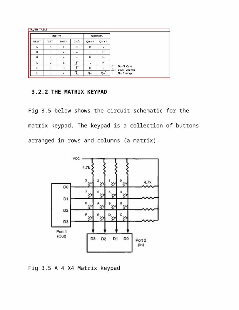
3.2.2 THE MATRIX KEYPAD
Fig 3.5 below shows the circuit schematic for the
matrix keypad. The keypad is a collection of buttons
arranged in rows and columns (a matrix).
Fig 3.5 A 4 X4 Matrix keypad

The rows and columns are connected to an input/output
(IO) port of the microcontroller. If no key has been
depressed, reading the input port will yield 1 s for
all columns since they are all connected to high (Vcc –
supply voltage). If all the rows are grounded and a key
is depressed, one of the columns will have 0 since the
key depressed provides the path to ground. It is the
function of the microcontroller to scan the keyboard
continuously to detect and identify the key that has
been depressed.
3.2.3 POWER SUPPLY UNIT
The 8051 microcontroller as well as other digital
devices operates with 5 volts to ground dc power
supply. To achieve this, we use a single 9 volts
battery which provides 9 volts dc which is regulated by

the 7805 voltage regulator IC (U1). The output of this
IC gives a stable dc voltage of 5V.
VI1 VO 3
GND
2
U17805
B19V C2
0.1uF
+5v
C14.7uF
+9V
Fig 3.6 Power supply unit for the burglar alarm
project.
Additionally, the 9V dc voltage from the battery will
be found useful in powering analog (non-digital)
components of the system, like the infrared transmitter
oscillator. The input and output capacitors are
provided for transient suppression and filtering.

3.2.4 MICROCONTROLLER CIRCUIT
The ATMEL 89C52 is a low power high performance CMOS 8-
bit microcontroller mainly designed for sequential
controlling operations. It has 8Kbytes of flash
programmable and erasable read only memory (PEROM) on
chip. This device is compatible with the industry
standard AT80C52 instruction set and pin out.
Therefore, the AT80C52 micro-controller shares a lot in
common with the AT8952, just like any other micro-
controller can be likened to a microcomputer. The on
chip flash memory allows the programs memory (code
memory) to be quickly reprogrammed using a non-volatile
memory programmer. Below is the circuit configuration
of the AT89C52 microcontroller.

XTAL218
XTAL119
ALE30EA31PSEN29
RST9
P0.0/AD0 39P0.1/AD1 38P0.2/AD2 37P0.3/AD3 36P0.4/AD4 35P0.5/AD5 34P0.6/AD6 33P0.7/AD7 32
P2.7/A15 28
P2.0/A8 21P2.1/A9 22P2.2/A10 23P2.3/A11 24P2.4/A12 25P2.5/A13 26P2.6/A14 27
P1.0/T21P1.1/T2EX2P1.23P1.34P1.45P1.56P1.67P1.78
P3.0/RXD 10P3.1/TXD 11P3.2/INT0 12P3.3/INT1 13P3.4/T0 14
P3.7/RD 17P3.6/W R 16P3.5/T1 15
AT89C52
80C52
C1
30pX1CRYSTALC2
30p
R110k
C310uF
5V Vcc
Fig 3.7 circuit configuration of the AT89C52
microcontroller.
Component list of the micro-controller section
IC1 = AT89C52 micro-controller
C1 and C2 = 30pf ceramic capacitor
X1 = 11.0592MHZ crystal oscillator
R1 = 10K

C3 = 10uF
3.2.5 OPERATION OF THE MICRO-CONTROLLER
XTAL218
XTAL119
ALE30EA31PSEN29
RST9
P0.0/AD0 39P0.1/AD1 38P0.2/AD2 37P0.3/AD3 36P0.4/AD4 35P0.5/AD5 34P0.6/AD6 33P0.7/AD7 32
P1.0/T21P1.1/T2EX2P1.23P1.34P1.45P1.56P1.67P1.78
P3.0/RXD 10P3.1/TXD 11P3.2/INT0 12P3.3/INT1 13P3.4/T0 14
P3.7/RD 17P3.6/W R 16P3.5/T1 15
P2.7/A15 28
P2.0/A8 21P2.1/A9 22P2.2/A10 23P2.3/A11 24P2.4/A12 25P2.5/A13 26P2.6/A14 27
AT89C52
AT89C52
1 2 34 5 67 8 9
0 #
1 2 3
A
B
C
D
D714
D613
D512
D411
D310
D29
D18
D07
E6
RW5
RS4
VSS
1VD
D2
VEE
3
LCDLM 016L
R210k
R110k
Q1C9014
RELAY9V
R310k
C310uF
D1DIODE
X1
CRYSTAL
C130pF
C230pF
From sensor
BATTERY9VBUZZER
BUZZER
5V
Fig 3.8 Circuit diagram of the burglar alarm system.
The AT89C52 micro-controller has a 40-pin dual inline
package feature (DIP). This micro-controller has been

configured to make use of 11.0592-megahertz (MHZ)
crystal oscillator. This crystal oscillator is
connected to pin 18 and 19 of the micro-controller
while it is connected to capacitor C1 and C2. Capacitor
C 3 and resistor R3 are provided for reset purposes.
These values are standard values. Pin 40 is connected
to the output of the voltage regulator. Pin 20 is
connected to ground. The keypad is connected to port 2,
while the LCD module (RT1012 16x2 ASCII LCD) data pins
are connected to port 1. The switch represents the
sensor connected to port 3, bit 2. Transistor Q1 drives
the 9 volts relay. Q1 is biased by R1 and R2. A buzzer
is used as the alarm bell; this can be replaced with
any other suitable alarm. Diode D1 is provided to
protect the transistor from “inductive kick” (Horowitz,
2003).

The program of operation for the microcontroller
circuit will be discussed in the next section.
3.3 SOFTWARE DEVELOPMENT
We have the alarm control panel: this consists mainly
of a small keypad, plus an additional ‘buzzer’ to
indicate that the alarm has sounded (Figure 3.8). The
alarm system is designed in such a way that the user –
having set the alarm by entering a four pass code via
the keypad – has time to open the door and leave the
room before the monitoring process starts. Similarly,
if the user opens the door when the system is armed, he
or she will have time to enter the password before the
alarm begins to sound.
Overall, the system is designed to operate as follows:
When initially activated, the system is in
‘Disarmed’ state.

In Disarmed state, the sensors are ignored. The
alarm does not sound. The
System remains in this state until the user enters
a valid password via the keypad. When a valid
password is entered, the system enters the ‘Arming’
state.
In Arming state, the system waits for 60 seconds,
to allow the user to leave the area before the
monitoring process begins. After 60 seconds, the
system enters the ‘Armed’ state.
In Armed state, the status of the various system
sensors is monitored. If the sensor is tripped, the
system enters ‘Disarming’ state. The keypad
activity is also monitored: if a correct password
is typed in, the system enters ‘Disarmed’ state.
In Disarming state, we assume that the door has
been opened by someone who may be an authorized

system user. The system remains in this state for
up to 60 seconds, after which, by default, it
enters ‘Intruder’ state. If, during the 60- second
period, the user enters the correct password, the
system enters ‘Disarmed’ state.
In Intruder state, an alarm will sound. The alarm
will keep sounding (indefinitely), until the
correct password is entered.
Overall, the burglar alarm system is somewhat
simplified, but the overall system architecture is
correct, and the code may be easily extended to add
additional features.
3.3.1 PROGRAM CODE
The program was written using M-IDE 51 compiler
following the design operation in the previous section.

Fig 3.9 is the simplified program flowchart for the
software architecture.

START
Alarm state = Disarmed
Sensors = Off
Sensor
Passcode
Alarm State = Disarmed
Pass Code
Alarm State= Arming
60secs
Alarm State = Armed
Sensor
60 secs
YES NO
YES
NO
NO
NO
YES
NO

Fig 3.9 Simplified flowchart for the software architecture
CHAPTER 4
RESULTS AND DISCUSSION
4.1 INTRODUCTION
To achieve reliable results and optimum performance
from any electronic construction project, specific
tests (static and dynamic) are carried out to determine
if the device is operating under the required standard
conditions. Also the precautions taken and safety
considerations made in achieving both the hardware and
software part of our work are considered.
4.2 MOTION DETECTOR CIRCUIT
As mentioned earlier, this consists of an infrared
transmitter and receiver
YESSound Alarm

4.2.1 INFRARED TRANSMITTER CIRCUIT
The transmitter was constructed using the CD4047
oscillator. The output of the oscillator was tested
using a multimeter in alternating current (ac) mode.
The output gave 4.45 volts.
4.2.2 INFRARED RECIEVER CIRCUIT
The three pin IR receiver used produced 7.3 volts on
its output when measured with a multimeter. If it
detects any IR beam, the output goes to 0 volts.
4.2.3 RESULTS FOR THE MOTION DETECTOR SYSTEM
Detection range for the motion sensor detector system
varies with battery strength and the reflecting object
surface. Its range is about 1.5 meters. The system was
demonstrated thus: the receiver output was connected to
a light emitting diode (LED). When an object enters the
zone, the LED starts blinking.
4.3 MICROCONTROLLER CIRCUIT
When the entire circuit is powered, the voltage drop
across each terminal of the crystal oscillator will be
between 2.3V to 2.5V to show that the crystal
oscillator is good. For the Microcontroller, regardless
of any assembled program, its entire port will be high
all through. It shows that the microcontroller is in
good order. A short blinking LED program was burnt into
the EEPROM of the microcontroller to test if the
microcontroller responded properly to the program.
4.4 STATIC TESTS
Here the various tests carried out on the components
without power supply input shall be discussed.
Capacitors

We tested the capacitors with the digital voltmeter in
the resistance mode. We observed their charging and
discharging times.
Diodes
The 1N4007 diodes gave a low resistance when forward
biased by the Digital voltmeter, and a high resistance
when reversed biased by the Digital voltmeter.
Relays
We tested the relay contacts when they were normally
closed and they were found to be continuous.
Also, the input terminals (across the relay coil) gave
a good resistance value showing that the relay coils
were good.
Resistors
The potentiometers gave resistance values varying from
0 Ω to 5.0k Ω in a fairly linear fashion. We also
confirmed the 100k Ω resistance value of the resistor
used in the MCU.
4.5 MOUNTING AND COMPONENT CONNECTIONS
All connections made between components were either
made via connecting wires or directly with solder. The
following steps were employed to achieve good
connection of components used in the project.
Soldering Iron tip was well scraped before
commencing soldering.
Good care was taken to avoid overheating of
components.
Solder sucker/extractor was used to remove improper
and unintended joints.
A digital multimeter was used for continuity,
resistance, isolation test, voltage and current
measurements.

Circuit Board preparation
We used a matrix board for mounting the most of our
circuit component. A matrix board was chosen for the
following reasons.
All connections are self isolating.
Difficulty in making unintended connections (i.e.
bridging lines)
Connection lines can be made with solder like that
of a PCB facilitating the tracing of errors during
soldering.

4.6 PROGRAMMING THE AT89C52
This was one of the most challenging parts of the whole
project. The program was written in C programming
language using the M-IDE studio application. The
program was tested using PROETUS version 7 (an advanced
microcontroller simulator). After all errors were
debugged, the program was loaded into the
microcontroller using the device below.

Fig 4.1 Program loader for the AT89C52
CHAPTER 5
CONCLUSION & RECOMMENDATION
5.1 CONCLUSION

From the circuit schematic, the write up and the tests
carried out, it can be concluded that the alarm system
is functional and can be installed were ever it is
required be it a commercial or residential asset to act
as the first line of defence before the arrival of the
police in the event that a burglary incident occurs.
5.2 RECOMMENDATION
A burglar alarm can initiate a considerable response by
police or private security personnel, who may leave
other important duties to race to the scene of the
alarm. Therefore, the following recommendations are
stated so as to avoid the problems that are most likely
to arise due to the issue of false alarms and on how to
make the system more effective:
- The active infrared detectors can be programmed to
ignore the first movement detected, as in when the

intruder moves from one detection zone to another,
and to sound the alarm only when the movement passes
through two or more detection zones within a
specified period of time.
- Another means of preventing false alarms is the dual-
technology motion detector. This is the more common
type of detector used in more sophisticated burglar
alarm systems. A dual-technology detector combines an
active infrared device and a microwave device in one
small unit. The active infrared device sees many
detection zones and measures the change in background
temperature as a target moves across them. At the
same time, the detector projects microwaves and
measures the Doppler shift when a target moves
through the protected space.
- If the alarm is to be used in commercial assets or
high security areas the following authorization

methods could be added to ensure the effectiveness of
the system e.g. addition of multiple codes, or a
fingerprint, badge, hand-geometry, retinal scan,
encrypted response generator, and other means that
are deemed secure for the asset in question.
REFERENCES
Dietel H.M. & Dietel P.J. (2003), “C How to Program” (4th
Edition), Prentice Hall, Pearson Education
Publishers

Horowitz P. & Winfield H., 2003, “The Art of Electronics”, 2nd
Ed., University Press, Cambridge-Great
Britain
Jorgensen D., (2009), “Literature Survey on Sensors & Actuators:
Infrared Proximity Sensor”, Department of Electrical &
Computer Engineering, Utah State University, USA
Allen, Samuel M. (2009) "Motion Sensors" Microsoft(R)
Encarta(R) [DVD]. Redmond, WA: Microsoft Corporation.
Theraja, B.L. & Theraja, A.K. (2005), “A Textbook of
Electrical Technology”, Revised 24th Edition, S. Chand &
Company Ltd., New Delhi, India
Tokhiem R. L. (1999), “Digital Electronics: Principles and
applications”, 5th Ed., the McGraw-Hill Companies Inc.,
USA
Pont M.J. (2002), “Embedded C”, Addision Wesley, Pearson
Education Publishers

8051 Microcontroller (2010, 18 August – Last Update).[Online]
Available: http://en.wikibooks.org/wiki/Embedded_Systems/8051_Microcontroller [2010, September 16]
Basic Principles of Burglar Alarms (2010, August 10).
[Online]
Not Available:
http://www.howtoinstallalarms.com/chapter-2-basic-
principles-of-alarms/basic-principles-burglar-alarm-
systems.php [2010, September 16]
Burglar Alarm (2010, 27 August -Last Update). [Online]
Available: http://en.wikipedia.org/wiki/Burglar_Alarm [2010,
September 16]
Gregory J., A Short History of Burglar Alarms (2007, 3
March – Last Update). [Online]

Available: http://ezinearticles.com/?A-Short-History-of-Burglar-
Alarms&id=475162 [2010, September 16]
Jones A. Types of Burglar Alarm System (2009, 12 April
-Last Update). [Online]
Available: http://ezinearticles.com/?Types-of-Burglar-Alarm-System---
All-You-Need-to-Know&id=2212440 [2010, September 16]
Microcontroller (2008, July – Last Update). [Online]
Available: http://en.wikipedia.org/wiki/Microcontroller [2010,
September 16]
Passive Infrared Sensor (2010, 13 September – Last
Update). [Online]
Available: http://en.wikipedia.org/wiki/Passive_Infrared_Sensor
[2010, September 16]


