Embed Size (px)
Citation preview
HAL Id: tel-02997195https://tel.archives-ouvertes.fr/tel-02997195
Submitted on 10 Nov 2020
HAL is a multi-disciplinary open accessarchive for the deposit and dissemination of sci-entific research documents, whether they are pub-lished or not. The documents may come fromteaching and research institutions in France orabroad, or from public or private research centers.
L’archive ouverte pluridisciplinaire HAL, estdestinée au dépôt et à la diffusion de documentsscientifiques de niveau recherche, publiés ou non,émanant des établissements d’enseignement et derecherche français ou étrangers, des laboratoirespublics ou privés.
Design tools for enriching the ceramics formsaesthetically by experimental treatments during and
post firingMohammed El Abd El-Raouf El-Gohari Gohari
To cite this version:Mohammed El Abd El-Raouf El-Gohari Gohari. Design tools for enriching the ceramics forms aes-thetically by experimental treatments during and post firing. History. Conservatoire national des artset metiers - CNAM, 2012. English. �NNT : 2012CNAM0824�. �tel-02997195�

CONSERVATOIRE NATIONAL DESARTS ET MÉTIERS
Ecole doctorale Abbé Grégoire
N�d'ordre :
THÈSE DE DOCTORAT
Histoire des Techniques
présentée par :
Mohammed Mortada Abd El-Raouf El-Gohari
Design Tools for Enriching the Ceramics Forms
Aesthetically by Experimental Treatments During and Post Firing
Analyse rétrospective et comparatiste du traitement
des surfaces céramiques anciennes pendant et après cuisson.Modélisation des glacures
soutenue le :
24 September 2012 à Paris devant les membres du jury :
THÈSE dirigée par
M. André Guillerme Professeur, Cnam, Directeur de Thèse
RAPPORTEURS
Mm. Amina Ebeid Professeur, Université de Helwan, RapporteurMm. Laurence Lestel Professeur, Université Pierre et Marie Curie, Rapporteur
EXAMINATEURS
M. Jean-Pierre Chevalier Professeur, Cnam, ExaminateurM. Renaud Caplain Maître de Conférences, Cnam, Examinateur


Dedication
I dedicate this dissertation to who was interested in my scientific fu-
ture my late father, Mortada, who was always a source of pride and
privilege, and my late mother who was a missing grace in my life since
she died when I was a child, who have helped so much and have given
me their fullest support. Particularly to my loving sister, Amany, and
her small family and to my brother, Hany, and his small family. I
thank my pretty daughter, Mariam, and my precious son, Mortada,
who I missed very much during writing this work, and who have put
up with these many years of research. Finally, I dedicate this work
to everyone teach me something in my life, everyone help me for any-
thing in my life or give me his nice smile, and my great family, my
uncles and my aunts, all of whom believed in diligence, science, arts
and the pursuit of academic excellence.


Acknowledgements
This dissertation contains the results attained during my PhD at
CNAM de Paris during the years 2008-2012. Four years at CNAM
have been the time of my life. In addition to the wonderful environ-
ment for pursuing advancement in history of ceramics, technology of
glazes and design ceramics kilns, the professors and students are ex-
traordinary. I am grateful for graduating from CNAM. There are of
course a group of people who made this possible and I would like to
express my thanks to them.
At the outset, I would like to express my deep gratitude and thanks
to my supervisor. Prof. Andre Guillerme. for his support throughout
my time at Conservatoire national des arts et metiers . His excellent
guidance has extensively contributed to successful finish of my Ph. D.
thesis. His talent, dedication, and enthusiasm have been my source of
inspiration.
I’m so glad to have the beneficial opportunity to work under supervi-
sion of prof. Jean-Pierre Chevallier in department of materiaux indus-
triels metalliques et ceramiques du CNAM and I’m very grateful to
him for his valuable advices, continuous help and fruitful discussions.
I am very thankful to my co-advisor Prof. Renaud CAPLAIN, for
his helpful suggestions, critical comments. I really appreciate the
theoretical background that was given to me by him. Indeed, I’m
grateful to him for the great experimental experience and support
that was offered to me by him.

I sincerely thank to all of group in department of materiaux indus-
triels metalliques et ceramiques du CNAM , Jean-Pierre C., Sebastien
Dubent, Zehoua Hamouche, Patrice L., Outsaphone Soumpholchare-
une, Aomar Ikhlef Gerard Ferriere Gerard Lalleve Fabrice M. Jacques
Bechet, Mickael PAYET, C. Nicolas, Henri Paqueton. I would like to
acknowledge Doc. Ing. Gerard Ferriere for his help with the image
analysis software. For their support, guidance, and friendship over
the past four years, I’m also indebted to.
I sincerely thanks Prof. Amina Ebaid and Prof. Laurence Lestel for
agreeing to be reporters for this thesis.
This research would not be possible without the generous scholarship
from the Egyptian Government which offers me four years grant to
accomplish my PhD research.
Last but not least, I want to take this opportunity to express my
gratitude to my , brother, sister, and my lovely babies. I dedicate
this thesis to them.

Resume
Dans les arts plastiques, le concept de la beaute doit etre associe aux
techniques sous-jacentes. L’artiste doit choisir et maıtriser ces tech-
niques afin de les appliquer a l’art en vue d’atteindre les resultats
esthetiques vises. Une approche scientifique de ces techniques a un
role important dans l’amelioration de leur application dans les arts
plastiques. Les ceramiques et poteries sont un domaine complexe ou
les reactions chimiques et les proprietes physiques des argiles et des
glacures doivent etre prises en compte. Dans ce domaine l’histoire
de la science etait un guide utile dans une telle recherche. Pour les
ceramiques, les reactions chimiques se produisant a la phase haute
temperature du processus de cuisson determinent essentiellement l’as-
pect final de la surface du produit. En consequence, changer les condi-
tions de ces reactions (profils de temperature, la nature de l’atmosphere
du four) etait une bonne methode pour obtenir de nouveaux aspects
de surface. L’atmosphere du four pendant et apres la cuisson permet-
tait de controler, dans une large mesure, l’aspect final des produits
ceramiques, et cela depend a la fois de la conception et de la mise en
place du four. L’etude de l’histoire des techniques ceramiques, dans
differentes civilisations, a conduis a un apercu des techniques de cuis-
son. La comprehension scientifique de ces techniques a mene a des
strategies en vue de modifier la conception du four et la pratique de
la cuisson.


Abstract
In Plastic arts ; with the concept of beauty there are also techniques,
artists choose between these techniques for apply art works matching
with aesthetic viewpoint. As well as science have important role in im-
proved applied arts and fine arts techniques. In ceramics and pottery
we are confronted with the chemicals reactions and physical properties
of clay and glaze which have deep roots in human history, so history
techniques will guide us in this research. In ceramic, chemical reac-
tions need high temperature as condition to exist (Firing process),
and that have main role in determined final appearance of surface
treatments for ceramics forms. When the chemical reactions and phy-
sical properties which happen in firing process are responsible of final
appearance and aesthetics treatments of ceramics forms, the changing
of reactions conditions was used for achieving new treatments for ce-
ramic surface beauty. The atmosphere of kiln during and after firing
process whom decide the final appearance for ceramics forms, presen-
ted as technique for modifying kiln structure as a factor of enriching
aesthetics treatments for ceramic surface. The history and science of
ceramics techniques in some civilizations was studied to understand
some firing techniques and its roles in ceramic surface esthetics. These
provided evidence with experimental study to design a new kiln which
can be used as a tool to enrich ceramics forms aesthetically.
vii


Resume
Introduction
Dans les arts plastiques, la beaute est associee aux techniques. L’artiste doit
choisir et maıtriser les techniques pour les appliquer en vue d’atteindre les
objectifs esthetiques. Une approche historique de ces techniques doit permettre
a l’artiste d’en accumuler les savoirs, d’en saisir l’epistemologie et l’heuristique
tandis qu’une approche mecanique et thermique permet d’ameliorer la qualite,
de diversifier la production, bref de definir la phenomenologie.
Ceramiques et poteries appartiennent a un domaine complexe ou les reactions
chimiques et les proprietes physiques des argiles et des glacures doivent etre prises
en compte. Cette histoire des methodes et des rationalites est precisee des le traite
de l’Art de terre, de son utilite, des emaux et du feu que Bernard Palissy publie
vers 1585, a Paris : �je te mettrai ici par ordre tous les secrets qu e j’ai trouve
en l’art de la terre, ensemble les compositions et divers effets des emaux : aussi te
dirai les diversites des terres argileuses qui sera un point lequel il te faudra bien
noter [1]�. Pour Palissy comme pour Brongniard, deux siecles plus tard, la raison
permet d’echapper aux secrets ; la technique, mot nouveau du XVIIIe siecle, ap-
plique concretement cette rationalite. L’histoire des techniques ceramiques, dans
differentes civilisations, nous mene a un panorama des techniques de cuisson.
ix

RESUME
La comprehension scientifique de ces techniques nous conduit a saisir les in-
telligences qui ont concu les fours que l’archeologie decouvre et a definir des
strategies en vue de modifier la conception du four et la pratique de la cuisson.
Ainsi pour les ceramiques, les reactions chimiques se produisant a la phase haute
temperature du processus de cuisson determinent essentiellement l’aspect final
de la surface du produit. En consequence, changer les conditions de ces reactions
(profils de temperature, la nature de l’atmosphere du four) est un bon moyen
d’obtenir de nouveaux aspects de surface. L’atmosphere du four pendant et apres
la cuisson permet de controler, dans une large mesure, l’aspect final des produits
ceramiques, et cela depend a la fois de la conception et de la mise en place du
four.
Contexte
La creation dans le domaine de la porcelaine est liee a divers facteurs dont le
ceramiste doit etre a meme de se servir. La multiplicite des facteurs revient a
la grande diversite des etapes par lesquelles passe la production ceramique ; les-
quelles etapes requierent des outils nombreux et divers qui evoluent en raison du
faconnage et de la production. Les principales etapes d’elaboration sont :
1- L’appret des pates.
2- Le moulage.
3- Les operations precedant le sechage.
4- Le sechage.
5- La premiere cuisson (cuisson stricto sensu).
6- Les applications de la couverture vitrifiee.
7- La deuxieme cuisson.
8- Les operations d’apres la cuisson (post-cuisson).
L’outil est lie a la fonction qu’il execute et la fonction est liee a l’une des
etapes de la production, et de cette relation naıt une relation etroite entre l’outil
x

RESUME
et l’etape a laquelle il est employe, ainsi que la diversite et la multiplicite des outils
dans le domaine de la ceramique. L’evolution dans le domaine de la ceramique
exige une evolution du projet, de la production et de ses outils.
L’evolution est rattachee a l’ensemble des etapes et apparaıt dans la forme
et la fonction du produit ceramique final, lequel rappelle que toutes les etapes
sont reliees et ne sont separees que par la specification, l’etude et la cuisson a
l’etape ou s’operent toutes les reactions chimiques ayant un certain impact sur
l’esthetique de la forme ceramique.
L’evolution du projet et de la production des fours de ceramique favorise
l’evolution dans le domaine de la ceramique, et de l’enrichissement du cote esthetique,
soit a l’etape du premier feu comme il apparaıt en cas de production de formes
ceramiques a partir de pates speciales modifiees par l’ajout de pate a papier[2] ;
il resulte de l’ajout de certaines matieres aux pates une modification de cer-
taines de leurs caracteristiques specifiques. Mais ceci requiert un abaissement
de la temperature interieure du four pour ne pas detruire les formes ; Lors de
la seconde cuisson, la production de la couverture vitrifiee cristallisee exige de
controler la temperature [3] ou de modifier la construction du four pour l’adap-
ter aux operations apres cuisson d’une maniere sure -ceramique Racco ou vernis
vitrifies salins.
La cuisson des formes ceramiques est un patrimoine de l’anthropocene. Elle
temoigne l’une des plus anciennes professions et par la divulgation des connais-
sances et la succession des decouvertes, elle demontre toute l’intelligence de l’homo
sapiens sapiens qui accroıt la connaissance de la ceramique en fonction des secrets
de la nature et de l’environnement ; c’est ainsi que les techniques de la cuisson se
sont diversifiees a travers les temps. La cuisson a evolue depuis la fosse jusqu’aux
fours tres elabores, a deux etages ou a plusieurs chambres de cuisson. L’evolution
s’est poursuivie jusqu’a l’emploi du four a gaz ou a l’electricite (moufle).
La construction des fours passe par deux etapes liees a la forme du four et a la
nature des materiaux (combustibles) employes au feu selon que l’on veut obtenir
une atmosphere oxydante ou reductrice.
xi

RESUME
Les techniques et les matieres employees pour la production des formes ceramiques
resultent de la difference de nature de la cuisson ; c’est ainsi que nous avons trouve
la forme du four convenable au genre du produit, car les fours employes pour la
production des formes ceramiques enveloppees de vernis vitrifie salin, necessite
une structure permettant le passage du chlorure de sodium (NaCl) a l’etat vapeur
pendant la cuisson et qui s’unit a une portion du silicate ajoute au corps de la
pate pour constituer la couche de vernis vitrifie a la surface. De meme que les
fours employes pour la production des formes ceramiques a reflets metalliques
doivent avoir une structure permettant d’employer des techniques de cuisson ren-
dant reductrice l’atmosphere du four. Le carbone s’unit avec l’oxygene se trouvant
a l’interieur du four et des oxydes metalliques enduits sur la surface des formes
pour former l’enduit vitrifie a brillant metallique.
D’apres les fouilles archeologiques effectuees dans differentes civilisations nous
avons remarque une diversite de modeles dans la construction et le plan des fours
ceramiques : au Japon on trouve le four (anagama)que est represente sur la figure
(1), compose d’une seule chambre voutee enterree au versant d’un plateau[4].
Le four(anagama) a influence le traitement esthetique de la surface ceramique.
Les fours grecs, qui sont representes sur la figure (2), permettant a la chaleur de
passer verticalement depuis la chambre inferieure jusqu’a la chambre superieure
par des ouvertures pratiquees dans la sole entre les deux chambres et vers une
ouverture dans sa partie superieure, le plan de construction du four devait etre
vertical[5].
En Chine, il y a un autre type de fours, dits fours horizontaux, ou le sens de la
chaleur interieure est horizontal, etant donne qu’elle passe a travers la chambre de
cuisson pour sortir par une cheminee elevee au fond de cette chambre, et de l’autre
cote se trouve le foyer[5] et ce en depit d’autres fours divers dans beaucoup de
civilisations, ce qui a abouti a produire des formes ceramiques de types esthetiques
divers.
xii

RESUME
Figure 1: Anagma de base ou une grotte four [6].
xiii

RESUME
Figure 2: a) Reconstructions de fours grec b)Plan et en coupe du four romain [7].
xiv

RESUME
C’est ainsi que la cuisson a une relation etroite avec l’esthetique de la forme
ceramique, et les fours dont les plans constituent le fondement de l’evolution dans
le domaine de la ceramique et de sa technique.
Cette recherche porte sur la structure et le mode de cuisson internes de cer-
tains fours dans les differentes civilisations ; elle s’applique aussi aux matieres,
aux impressions esthetiques produites par les formes ceramique. De cette page
d’histoire technique on tentera d’en deduire de quoi construire (ou recreer) un four
permettant d’effectuer certaines operations experimentales concernant la cuisson
ou la post-cuisson pour obtenir des traitements esthetiques sur les surfaces. Etant
donne ce que les outils (fours) peuvent realiser comme evolution dans le domaine
de l’industrie ceramique, et le traitement esthetique des surfaces, ainsi que ce que
peut realiser la recherche et l’union des differentes techniques que le ceramiste
employait dans les civilisations passees, pour l’enrichissement des procedes et des
techniques des traitements esthetiques des surfaces ceramiques.
Etant donnees l’importance et les circonstances de la cuisson et vu que cette
operation pendant laquelle s’effectuent les reactions chimiques qui influencent
beaucoup la qualite des produits ceramiques et la diversite des facteurs qui in-
fluent sur ces reactions pendant ou apres la cuisson∗, le probleme du chercheur
se resume en une tentative d’etude et de re-creation de plans de fours ceramiques
en accord avec des operations effectuees pendant la cuisson , et les operations de
traitement apres cuisson pour contribuer a l’enrichissement des procedes et des
techniques des traitements esthetiques des surfaces.
∗Ce qui veut dire les procedures realisees pendant le cuisson et affectant l’esthetique de la
forme, la construction du four ayant un role dans sa realisation sans lequel elle ne peut etre
effectuee :
1- La possibilite d’effectuer des operations pendant et apres la cuisson influant positivement
sur l’esthetique de la forme des pieces.
2- La possibilite de modifier le plan et la construction des fours ceramiques de facon a per-
xv

RESUME
Contributions de la These
La separation de l’art et de la science ont ete dans le debut de la Renaissance, et
la specialisation dans divers domaines a commence. Malgre les progres qui realises
grace a cette separation, il y a des points communs entre les sciences appliques et
l’art, et la recherche sur ces points peut enrichir chacune des deux. En raison de la
relation entre l’art, la technologie et la science qui apparaissent dans l’evolution
et l’histoire des techniques de la ceramique, cette recherche vise a mettre en
evidence ces points et de profiter d’eux dans la technologie du four et la cuisson
de conduction avec les effets relatifs sur les traitements esthetiques de la forme
de la ceramique. L’etude historique de ces techniques avec l’etude scientifique
a permis de decouvrir que le progres scientifique a conduit a disparaıtre ou a
modifier certaines technologies. Revive ces technologies a conduit a la creation de
la technologie moderne d’utiliser le four comme un outil pour enrichir l’esthetique
de surfaces ceramique.
Notre etude historique porte sur deux types de ceramiques historiques.
1-la decoration de reflexion metallique, est apparu en Irak pendant le califat
abbasside (750-1258) : le milieu reducteur du four etant le procede principal pour
produire cet oxyde. Cette technique passe en Egypte puis vers le nord de l’Afrique ;
de la en Espagne et en Italie. Mais tandis qu’opere l’acculturation mecanique, les
conditions de cuisson ont glisse de redaction a oxydation.
2-la decoration de fissure (craquele) qui ont ete produites premiere fois en
XI siecle ou Chine pendant la dynastie Sung (960-1279). Cette technique a ete
utilisee pour decorer les cinq porcelaines celebres en cette dynastie . Considerant
que, l’atmosphere reduction et la structure du four c’est l’effet principale de la
production de ces styles de la ceramique.
Pour reconnaıtre les procedes et les conditions de cuisson dans l’histoire de
la ceramique, nous nous sommes referes au maıtre, Brongniart, qui a su classer
differents types d’art ceramique et de poterie. L’atmosphere de cuisson a ete
mettre d’effectuer certaines operations pouvant influer sur l’esthetique de la forme des pieces.
xvi

RESUME
Figure 3: Poterie Jomon, Becher et le couvercle. British Museum OA+.20,
AN401059
realisee dans la cuisson primitive et dans les fours a combustible. La structure de
la cuisson primitive affecte au degre pres la reduction ainsi que le type de four
et le carburant. Dans le classe des poteries a pate tendre et terres cuites, ile y
a styles qui traite par condition de mise a feu comme Jomon poteries, qui a ete
fabrique au Japon (10.000 BC),que est represente sur la figure(3), poteries noires
et rouges polies ou ”black topped” (avec le haut colore en noir), qui a ete fabrique
en Egypte et au Soudan (3500 BC) que est represente sur la figure(4), rouge-noir
poteries (3500 - 3300 avant JC), et de l’anthracite noir poterie,que est represente
sur la figure(5).
On montre que le style des ceramiques vernissees decorees en fonction des
conditions de cuisson sont
• Raku : vaisselle en pierre avec lime glacure, Japonaise raku est une pote-
rie creee par les descendants de la famille Raku pour la ceremonie du the
xvii
RESUME
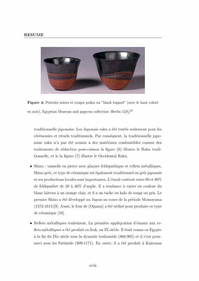
Figure 4: Poteries noires et rouges polies ou ”black topped” (avec le haut colore
en noir), Egyptian Museum and papyrus collection -Berlin 12Sj43
traditionnelle japonaise. Les Japonais raku a ete tentee seulement pour les
ceremonies et rituels traditionnels. Par consequent, la traditionnelle japo-
naise raku n’a pas ete soumis a des materiaux combustibles comme des
traitements de reduction post-cuisson la figure (6) illustre le Raku tradi-
tionnelle, et le la figure (7) illustre le Occidental Raku.
• Shino : vaisselle en pierre avec glacure feldspathique et reflets metalliques,
Shino gres, ce type de ceramique est egalement traditionnel en gres japonais
et ses productions locales sont importantes. L’email contient entre 60 et 80%
de feldspathet de 20 a 40% d’argile. Il a tendance a varier en couleur du
blanc laiteux a un orange clair, et il a un tache ou halo de rouge ou gris. Le
premier Shino a ete developpe au Japon au cours de la periode Momoyama
(1573-1615)[9]. Aussi, le four de (Ogama) a ete utilise pour produire ce type
de ceramique [10].
• Reflets metalliques traitement, La premiere appliqcation d’emaux aux re-
flets metalliques a ete produit en Irak, au IX siecle. Il etait connu en Egypte
a la fin du IXe siecle sous la dynastie toulounide (868-905) et il s’est pour-
suivi sous les Fatimide (909-1171). En outre, il a ete produit a Kairouan
xviii

RESUME
Figure 5: Tasse de coquille mince de la culture de Longshan decouvert dans le
Shandong, Chin, Peking University
xix

RESUME
Figure 6: La traditionnel raku the bol- Rouge, en gres rouge avec la permission
glacure transparente, Musee Duxbury.MA.[8]
(Tunisie) en IX siecle [11, 12, 13]. Il y avait ALORS deux types de reflets
metalliques decorations qui sont utilises dans IX siecle utilises : le lustre
polychrome qui etait rare et monochrome.
• Vase en terre cuite avec un eclat emaille ;
• les porcelaines chinois : four de Ru, four de Jun, four de Guan, et four de
Ge. Le four Ru est l’un des fours imperiaux de la dynastie Song du Nord
[14]. Il a ete produit pour a peu pres 20 ans seulement. Aujourd’hui, ce
style est tres rare. Il n’y a que 70 pieces de Ru qui ont ete recueillies dans
le monde [15].
Porcelaine de Jun trouvee dans le Juntai, Yuzhou ville, province du Henan.
La couche d’email est epaisse la ou il a ete emaillee deux fois. La gamme
de couleur du vernis s’etend du vert au bleu ciel, bleu pale, rose pourpre,
rouge au violet.
Porcelaine de Guan produite pour l’usage a la cour imperiale apres la des-
truction du four Ru. L’empereur Huizong avait ordonne la construction de
xx

RESUME
Figure 7: � Occidental Raku � avec traitement metallique de glacure par effet
de SnCl2 fumant, creee par James C. Watkins
xxi

RESUME
Figure 8: Bol de the, shino type, Mino avec Shino emaux couvrir par peints en
oxyde de fer, Musee national de Tokyo.
xxii

RESUME
Figure 9: Bol, nezumi-shino type, Mino , Azuchi-Momoyama Periode 16e au 17e
siecle, Musee national de Tokyo.
xxiii

RESUME
Figure 10: (Plat au porte-etendard),Irak ,X siecle, decoree par un lustre metallique
monochrome sur glacure opacifier, musee du Louvre, departement des arts isla-
miques, MAO 23
xxiv

RESUME
Figure 11: Ru coupe de Qingliangsi, Region de Baofeng, province du Henan, nord
de la Chine, dynastie Song, fin du XIe ou debut du XIIe siecle, British Museum
OA 1971.9-21.1
xxv

RESUME
Figure 12: Imperial Jun vaisselle ; Song du Nord
ce style dans le nord. Il y avait aussi le four Guan au sud ou ont ete produit
pour les nouveaux chapitaux Linan.
Les couleurs des glacures de cette porcelaine sont bleu-vert, blanches, brillantes,
grises et jaune vertes,. On devine des fissures qui couvrent la surface : ; elles
peuvent varier en epaisseur et en surface.
L’histoire technologique de la cuisson met clairement en evidence la relation
entre traitement esthetique des styles et modes de cuisson-structure du four. Ou
les modes des cuissons en feu ouvert peuvent etre classes en cuisson
• par pile sans canal de foyer ,
• pile avec canal de foyer vertical
• pile avec canal de foyer horizonta
xxvi

RESUME
Figure 13: Guan porcelaine de Nord
xxvii

RESUME
Figure 14: Ge cruche d’eau, dynastie Song
La figure(15) illustre l’influence de la methode de cuisson des poteries en
feu ouvert quand les poteries sont rangees sans canal de foyer , la figure(16)
illustre l’influencer de la methode de cuisson de poteries en feu ouvert tant que
les poteries etre organisee pour former un canal de foyer vertical, et la figure(17)
illustre l’influencer de la methode de cuisson de poteries en feu ouvert tant que
les poteries sont rangees pour former un canal de foyer horizontal.
Les modes de cuissons en fosse legere, en fosse profonde ou en enceinte circu-
laire permettent de faire des traitements, mais la cuisson dans le four, ne permet
pas de faire ce traitement et l’evolution du four prend une forme architecturale.
Par consequent, les traitements esthetiques des les poteries, a travers l’histoire de
la ceramique sont en relation avec modes de cuisson, la structure du four, et les
sources de chaleur. La figure (18) illustre conception de la place des cuissons en
fosse legere, et le figure (19) illustre conception de la place des cuissons en fosse
profonde.
xxviii

RESUME
Figure 15: Diagramme illustrant l’influence de la methode de cuisson de poteries
en feu ouvert tant que les poteries sont organisees sans canal de foyer.
Figure 16: Diagramme illustre l’influence de la methode de cuisson de poteries a
feu ouvert tant que les poteries etre organisee pour former un canal de foyer vertical
xxix

RESUME
Figure 17: Diagramme illustrant l’influence de la methode de cuisson de poteries
en feu ouvert tant que les poteries etre organisee pour former un canal de foyer
horizontal
Figure 18: Schema demontrant la structure de la cuisson en fosse
xxx

RESUME
Figure 19: Schema de demontrer la structure de la cuisson en fosse profonde
Les glacures sont des traces materielles qui sont traitees au cours de cuisson.
Le traitement des aspects qui affectent la glacure peut etre determine a travers des
reactions chimiques de ses composants et de ses proprietes physiques, c’est pour-
quoi la nature et la formation d’email sont presentes pour concevoir la glacure qui
represente une entree pour des reactions chimiques. La composition des glacures
repond a la formule de Seger - ou unitaire-, comme le montre l’equation (1). On
a presente plusieurs facons des conversions de Formules / Ponderales / Molaires
/ Seger, ce qui nous a permis de traiter la glacure comme un compose chimique.
RO
R2O
.{R2O3} .
{RO2
R2O5
(1)
La importance de Sager formula est de determiner la formule chimique des
glacures qui sont necessaires pour la conception de reactions chimiques. Donc
MapleTM logiciel est utilise pour faire conversion de formules de seger a forme
d’une liste de % molaires, et pour faire conversion de forme d’une liste de %
molaires a formules de seger. Les figures (20) et (21) illustrent les fenetre du
logiciel MapleTM et les calculs pour conversions.
xxxi

RESUME
Fig
ure
20:
Fen
etre
de
Map
leT
Mqu
ies
tu
tilise
pou
rfa
ire
conver
sion
de
form
ule
sd
ese
ger
afo
rme
d’u
ne
list
ed
e%
mol
aire
s
xxxii

RESUME
Fig
ure
21:
Fen
etre
de
Map
leT
Mqu
ies
tu
tili
sep
our
fair
eco
nver
sion
de
form
ed
’un
eli
ste
de
%m
ola
ires
afo
rmu
les
de
sege
r.
xxxiii

RESUME
En utilisant la formule de Seger, il peut identifier quelques-unes des caracteristiques
des glacures. On a discute ses caracteristiques dans cet these. Determiner le
nombre relatif de molecule oxydes est un processus complexe dans la modelisation
des glacures , ou il ya beaucoup d’usines doivent etre pris en compte pour
determiner le nombre par rapport a une formule de glacure. La ratio de de
l’oxygene est calcule par l’equation suivante :
Oratio =Moloxygen
MolSi +MolB(2)
Cette ratio est de 2 a 3 pour toutes les emaux [16], et ile est avec la mo-
laire de l’alumine Al2O3 peut donner idee de la temperature de cuisson Qui,
theoriquement, pourrait determiner par Lengersdorf facteurs de flux(F).
(F est le facteur de flux qui est calculee d’apres l’equation suivante [17] :
F =
∑Sifi∑Sjfj
× 100 (3)
FT est la temperature de traitement thermique qui est calculee a partir de
l’equation suivante [17] :
FT =161.21789− F
0.10252(4)
les Lengersdorff facteurs de flux est presente dans le tableau (1) :
Ratio du Thorpe est utilise pour controler la solubilite du plomb dans la
structure glacure qui est calculee a partir de l’equation suivante :
Moles de basiques+Moles de Alumine
Moles de Oxydes acides× 223
60, (5)
xxxiv

RESUME
Figure 22: Diagrammes illustre la relation entre la ratio de SiO2, Al2O3 a coins
10,12,14 et 16.
xxxv

RESUME
Table 1: Caracteristiques et coefficients specifiques utilises pour la preparation des
glacures [18]
Oxyde Masse Winkelmannand Dietzel partial Lengersdorff Appen
molaire Scott partial coefficients flux coeffi-
coefficients factors cients
Na2O 62 333.3 0.7 0.88 1.590
K2O 94.2 283.3 0.7 0.88 1.575
MgO 40.3 003.3 6.6 0.54 1.610
CaO 56.1 166.7 4.8 0.58 1.730
ZnO 81.4 060.0 4.7 0.60 1.710
BaO 153.3 100.0 3.7 0.60 1.880
Al2O3 102 166.7 6.2 0.32 1.520
Fe2O3 159.7 133.3 - 0.7 -
B2O3 69.6 003.3 0.8 1 1.470
SiO2 60.1 026.7 3.4 0.38 1.459
TiO2 79.9 136.7 4.1 0.38 2.080
P2O5 141.5 066.7 - - -
MnO 70.94 - - 0.6 -
cette equation a ete enonce comme suit :
Ro+ Al2O3
RO2
= 0.5(comme maximale), (6)
Le module d’allongement (ou module de Young) d’une glacure est calcule a
xxxvi

RESUME
partir de l’equation suivante :
E =∑
aiEi, (7)
Table 2: Facteurs pour le calcul de module de Young a partir de compositions
chimiques [19]
Oxydes Facteurs des Winkelmann et schott (94)
A∗ B§ C¶
Na2O 6.0 9.8 6.9
K2O 3.9 6.9 2.9
MgO - 3.9 2.9
CaO 6.9 6.9 -
ZnO 5.1 9.8 -
BaO - 6.9 2.9
Al2O3 17.6 14.7 12.7
Fe2O3
B2O3 - 5.9 2.5
SiO2 6.9 6.9 6.9
TiO2
P2O5 - - 6.9
PbO 4.5 - 5.4
As2O5 3.9 3.9 3.9
∗Facteurs sous A sont pour glacure ou verre libres de B2O3,P2O5,BaO,MgO.§Facteurs sous B sont pour glacure ou verre libres de PbO,P2O5.¶Facteurs sous C sont pour glacure ou verre libres de borosilicates, borosilicates de plomb,et
xxxvii

RESUME
E module de Young , ai % ponderal des oxydes et Ei les Winkelmann et Schott
coefficients tel que presente dans le tableau(2)
L’aspect de la glacure pas determine par ses compositions seulement, mais
aussi par les conditions de ces reactions qui existe pendant la cuisson et propriete
physique qui peuvent etre identifies par les compositions. En outre, une partie de
ce qui determine les caracteristiques physiques de la glacure est La relation entre
les differentes phases : du verre, des cristaux et des liquides. On a discutes cette re-
lation pour demontrer l’effet du taux de chauffage et le refroidissement ainsi que le
calendrier de cuisson comme une operation pour produire Les glacures cristallines.
Table 3: Composition en unites de masse qui Doat Taxile utilise pour produire la glacure
cristalline a Sevres
Composition Frit No.1 Frit No.2
Dry carbonate of potash, (K2CO3) 138 069, 0
Zink Oxide,(ZnO) 162 202, 5
Quartz, (SiO2) 360 350, 0
L’expression de la structure glacure en formule de Seger est presentee pour
organiser les oxydes metalliques presents dans les produits constitutifs de glacure.
Le traitement chimique des anciennes glacures des reflets metalliques et celadon
ont ete presentes pour reconnaıtre les compositions d’email qui decouvert par
des etudes anterieures, ainsi que son colorant. Or, la composition de la glacure
ancienne peut etre conclue pour proposer une matiere premiere a partir de leur
analyse d’oxyde. le tableau (4)represente le Fe2+ / Fe3+ ratio, longueur d’onde et
couleur de glacure pour quelque echantillons de ancienne Ru porcelaine.
phosphates.
xxxviii

RESUME
Figure 23: Calendrier pour vernis cristallin comme fait par George Juliano
Le traitement physique des glacures qui peut produire un faıencage a la sur-
face est presente pour aider a concevoir un type de glacure original. Nous avons
ainsi reconsidere la theorie chimique des proprietes de la glacure et precise sa for-
mulation chimique pour affiner le glacage dans un sens esthetique, a la maniere
de Brongniart.
En outre, le calcul de la structure chimique et l’analyse des oxydes d’email
sont experimentes pour simuler l’echantillonnage du four Ru. La conclusion est
que l’echantillon contient un corps de porcelaine qui a resiste a un choc thermique
et qu’il a un faible coefficient de dilatation thermique. Par consequent, l’etude
incrementielle qui permet de simuler et de concevoir le corps de porcelaine et
email est important pour produire le corps d’argile et de glacure qui sont aptes
a etre traites par un choc thermique comme un traitement mecanique. Cette
methode amene aussi a concevoir celle qui etablit un choc thermique lors de la
periode refroidissement.
xxxix

RESUME
Table 4: la Ratio de Fe2+ / Fe3+ ,longueur d’onde (λD) et couleur de glacure pour
quelque echantillons de ancienne Ru porcelaine.
NO Fe2+ Fe3+ Fe2+ / Fe3+ (λD)(nm) couleur de
glacure
I (%) I (%)
R16 79.2 20.8 3.81 420 vert
R18 78.4 21.6 3.63 430 vert
R1 76.1 23.9 3.18 520 vert
R14 68.1 31.9 2.13 570 vert
R26 66.8 33.2 2.01 570 vert pomme
R15 65.8 34.2 1.92 600 vert pomme
R27 64.1 35.9 1.79 600 vert pomme
xl

RESUME
Tab
le5:
Cal
cul
du
pou
rcen
tage
de
mat
iere
sp
rem
iere
sp
our
lare
cett
ed
eR
47b
oxydes
par
ties
en
gaz
mat
iere
sSiO
2A
l 2O
3C
aOK
2O
MnO
TiO
2F
e 2O
3p
oids
poi
ds
volu
me
%m
atie
res
dio
xyde
de
silici
um
SiO
2
24.4
624
.46
21.7
5%
Kao
lin
Al 2
O3·2
SiO
2·2
H2O
38.3
330
.57
0.08
0.77
0.01
0.07
0.71
81.3
010.4
5H2O
13.9Lt2
0C
72.3
0%
K2C
O3
1.43
2.12
0.67
CO
21.
32Lt1
200C
1.88
%
CaC
O3
1.29
2.33
1.01
CO
22.
03Lt8
00C
2.07
%
TiO
21.
081.
090.
97%
Fe 3
O4
1.20
1.20
1.03
%
%ox
yde
62.7
930
.57
1.37
2.2
0.01
1.15
1.91
100%
xli

RESUME
Tab
le6:
Les
vale
urs
calc
ule
esd
esp
rop
riet
esm
ecan
iqu
esen
emai
ld
ep
orce
lain
eet
leco
rps
de
Ru
porc
elain
e
Code
αglaze−αbody
σglaze
σbody
σglaze-σbody
Not
e
echan
tillon
10−
7K−
1M
Ps
MP
sM
Ps
No.
R40
37.3
2-1
84.8
47.
39-1
92.2
3te
nse
ur
des
contr
ainte∗
R41
36.7
8-1
82.0
97.
28-1
89.3
7te
nse
ur
des
contr
ainte
R42
38.8
2-1
92.3
77.
69-2
00.0
7te
nse
ur
des
contr
ainte
R43
43.2
2-2
20.5
88.
82-2
29.4
1te
nse
ur
des
contr
ainte
R44
40.8
3-2
01.1
78.
04-2
09.2
2te
nse
ur
des
contr
ainte
R47
37.1
0-1
83.5
77.
34-1
90.9
1te
nse
ur
des
contr
ainte
R27
135
.34
-174
.39
6.97
-181
.36
tense
ur
des
contr
ainte
R27
537
.51
-186
.84
7.47
-194
.32
tense
ur
des
contr
ainte
R33
034
.35
-195
.03
7.80
-202
.83
tense
ur
des
contr
ainte
R33
336
.79
-185
.03
7.40
-192
.43
tense
ur
des
contr
ainte
R33
924
.21
-122
.77
4.91
-127
.68
tense
ur
des
contr
ainte
R38
235
.61
-179
.75
7.19
-186
.93
tense
ur
des
contr
ainte
xlii

RESUME
Figure 24: Traitement des Fissures esthetique , cree par un choc thermique a 900
˚C.
Comme pour les traitements chimiques, la methode de conception de la glacure
permet a preparer des glacures qui sont appropries pour reagir avec l’atmosphere
du four pour produire des phases metalliques de fer et de cuivre comme une
technique traditionnelle. Cette phase metallique a ete concu pour reagir sous
atmosphere de sulfuration pour produire des oxydes sulfures de fer ou cuivre
qui donnent des glacures de differentes couleurs. Le diagramme d’Ellingham et
Cu : Fe : systeme de S sont utilises pour reguler la relation entre la structure
de la glacure et la temperature de traitement de sulfuration. Par consequent,
en utilisant le four pour controler les reactions chimiques et en s ’appuyant sur
etude scientifique en laboratoire, on montre que les potiers avaient une excel-
lente connaissance de la thermomecanique des fours pour concevoir les emaux,
les craquelures et le faıencage. Ces arts de la ceramiques qui Brongniart a pour
∗Fissure est cree lorsque le tenseur des contrainte au-dessus de 160 MPs ,la resistance a la
traction de glacure commun
xliii

RESUME
Figure 25: Traitement des Fissures esthetique , cree par un choc thermique a
1100 C.
xliv

RESUME
Figure 26: systeme de Cu−S [20].
la premiere fois rationalise sont devenus des technologies dont on peut tirer de
nouvelles methodes de surfacage notamment pour la dorure et l’argenture des
glacures ceramiques. On peut obtenir en plus quelques autres couleurs comme le
noir avec un eclat metallique, bleu indigo et le bleu de paon. On se refere aux dix
mille couleurs ou teintes que Chevreul a etabli a la Manufacture de tapisserie des
Gobelins au milieu du XIXe siecle.
On illustre l’analyse fonctionnelle et la conception d’un nouveau four qui
est tente d’appliquer les traitements historiques pendant la cuisson et de ses
evolutions. En general, plutot que, en particulier, l’architecture d’un four inter-
mittent reformule dans le cas d’un additif soit des fonctions pour produire des
fissure et des couleurs en reflet metallique sur la surface de ceramique vernissee.
Dans le cadre du fonctionnel, les resultats des etudes historiques et experimentales
xlv

RESUME
Figure 27: systeme deFe−S[20].
xlvi

RESUME
Figure 28: Digramme pieuvre illustre les fonction contrainte, fonction principale
et caracterisation des elements du milieu exterieur(EME) pour nouveau four
sont representees dans le cadre des exigences, des services et des solutions atten-
dues.
La methode APTE ∗est utilise pour expliquer le plan de nouveau four. Etude
mathematique est utilisee pour estimer l’energie qui est necessaire pour faire
fonctionner le four, et le choix des materiaux refractaires pour la construction
du four. Un programme d’elements finis (ANSYS) est utilise pour evaluer la
deformation de la structure du four. La figure (28) illustre le digramme pieuvre
pour nouveau four.
Un four special qui est utilise comme un outil pour les traitements esthetiques,
et tenant compte le traitement chimique des gaz et la fumee de sortir du four. Il
peut etre utilise pour regler la temperature de l’cuisson de formes ceramique en
1300 C. L’architecture de ce four permet d’avoir des procedures suivantes :
∗APTE est l’application des techniques d’Entreprises, une methode d’analyse fonctionnelle
et analyse de la valeur pour la gestion de projets d’innovation et d’optimisation.
xlvii

RESUME
• Faire la cuisson dans l’atmosphere normale a partir du debut jusqu’a la
glacure bien cuit (de 20 a 1300 C).
• Autorises a passer quelques materiaux qui changent l’atmosphere du four a
la temperature appropriee.
• Distribution de gaz et de fumee, qui traitent les surfaces des ceramiques a
l’interieur du four.
• Serree fermees du four afin de ne pas fuir de gaz dans l’air en place.
Les figures (29) et (30) illustrent le nouveau four de choc thermique et de traite-
ment chimique quand il est ferme et quand il est ouvert.
La structure du four est composee de trois parties : la premiere est la base, une
paroi en forme de cercle, d’autre part est sous forme de cylindre et la troisieme
partie est pointe dome. Le figure (29) illustre certains coupes de nouveau four.
xlviii

RESUME
Figure 29: Le nouveau four de choc thermique et de traitement chimique quand
il est ferme
xlix

RESUME
Figure 30: Le nouveau four de choc thermique et de traitement chimique quand
il est ouvert
l

RESUME
Fig
ure
31:
Cou
pe
vert
ical
de
nou
veau
fou
r
li

RESUME
Futurs travaux
Les futurs travaux devraient explorer d’autres possibilites et voies dans lesquelles
cette these pourrait conduire a enrichir, dans la ceramique, le point de vue his-
torique et esthetique. Les principales perspectives devraient inclure :
1. La mise en œuvre du four :
En raison de la possibilite de produire des reflets metalliques, des do-
rures, et des craquements de decorations, un tel four est necessaire pour
la pedagogie, la recherche et l’experimentation, pour l’enseignement par la
recherche et pour la recherche. Les technologies tres precises de choc ther-
mique et de choc chimique ont besoin de ce type de four, c’est pourquoi
l’etude experimentale de ces technologies doit continuer pour appliquer ces
techniques et specifier les palettes actuelles et la gamme des couleurs comme
une fonction de traitement pendant la cuisson et la composition de glacure.
Cette recherche devrait conduire a decouvrir d’autres parametres d’incerti-
tudes et a les rectifier en consequence.
En outre, la recherche d’autres minerais metalliques pourrait amener a de
nouveaux traitements esthetiques particuliers par la methode de conception
de glacures et a l’aide de diagrammes de phase et des formules d’Ellingham.
Or cette recherche peut conduire a adapter la technologie de la couleur de la
glacure, ou de creer de nouveaux traitements dont les conditions de cuisson
sont controlees par la mise en œuvre du nouveau four.
2. La verification et l’evaluation de l’utilisation de la technique de
Craqueles par choc thermique en presence des techniques et des
traitements chimiques :
L’utilisation du choc thermique pourrait etre verifie des craquelees sur les
surface de glacures aux memes tempes de la possibilite de faire un traitement
chimique pour avoir une craqueles colorees. La recherche sur la compatibilite
lii

RESUME
entre la resistance au choc thermique et le coefficient de dilatation thermique
du corps de l’argile et la glacure peut etre amene a produire motifs des
craqueles sur la glacure.
3. Recommandation pour plus de recherches scientifiques et experimentales
en histoire des techniques de ceramiques :
Le temps fait defaut a l’histoire. Notre investissement dans cette recherche
nous a campe devant le four theorique et pratique. Palissy, Brongniard,
Chevreul, sont les herauts de la rationalite technologique auxquels nous de-
vons constamment nous referer et que nous n’avons pas pu consacrer tout le
temps necessaire a leur puissance intellectuelle et heuristique. La recherche
scientifique et experimentale en histoire des techniques ceramiques est fon-
damentale aux pratiques artistiques et ceramiques, elle mene a decouvrir et
mettre en valeur les techniques anciennes, a les redecouvrir, a les retravailler
pour en faire des technologies.
liii


Contents
Abstract vii
Resume ix
List of Figures lxiii
List of Tables lxxvii
Introduction 1
1 literature review 9
1.1 Relationship between some disciplines and ceramics . . . . . . . . 10
1.1.1 History . . . . . . . . . . . . . . . . . . . . . . . . . . . . . 10
1.1.2 Archeology . . . . . . . . . . . . . . . . . . . . . . . . . . 11
1.1.3 art . . . . . . . . . . . . . . . . . . . . . . . . . . . . . . . 12
1.1.4 Science . . . . . . . . . . . . . . . . . . . . . . . . . . . . . 15
1.1.4.1 Relationship between science and technology. . . 16
1.1.4.2 Relationship between science research and art. . . 18
1.2 Alexandre BRONGNIART (1770-1847) . . . . . . . . . . . . . . . 19
1.3 Manufacture nationale de Sevres . . . . . . . . . . . . . . . . . . . 27
lv

CONTENTS
1.4 General Factors Which Affecting the Productions of Promotional
Ceramics . . . . . . . . . . . . . . . . . . . . . . . . . . . . . . . 32
1.4.1 available materials . . . . . . . . . . . . . . . . . . . . . . 32
1.4.2 Production Technologies . . . . . . . . . . . . . . . . . . . 38
1.4.3 Philosophy and Concept of Art . . . . . . . . . . . . . . . 39
1.5 Important Role of Science in Ceramics Art . . . . . . . . . . . . . 40
1.6 Important Role of History in Ceramics Art . . . . . . . . . . . . . 40
1.7 Correlation Between Kiln Technology and Finale Appearance of
Ceramic Forms . . . . . . . . . . . . . . . . . . . . . . . . . . . . 43
1.7.1 Atmosphere of kiln as referring to amount of oxygen: . . . 46
1.7.1.1 Reduction Atmosphere . . . . . . . . . . . . . . . 46
1.7.1.2 Oxidation Atmosphere . . . . . . . . . . . . . . . 48
1.7.1.3 Neutral Atmosphere . . . . . . . . . . . . . . . . 48
1.7.2 Condition of firing as referring to heating rate and inserting
vapor of substances : . . . . . . . . . . . . . . . . . . . . . 50
1.7.2.1 salt firing . . . . . . . . . . . . . . . . . . . . . . 50
1.7.2.2 Crystalline Glaze . . . . . . . . . . . . . . . . . . 50
1.8 Electric kiln . . . . . . . . . . . . . . . . . . . . . . . . . . . . . . 55
1.9 Electric Kiln with ventilation system and oxidation atmosphere . 56
1.10 Kiln as condition to reactions . . . . . . . . . . . . . . . . . . . . 57
2 Ceramics history and firing process 61
2.1 Introduction . . . . . . . . . . . . . . . . . . . . . . . . . . . . . . 61
2.2 Classification of ceramics wares . . . . . . . . . . . . . . . . . . . 62
2.3 History of ceramics that had treated during or after firing process. 66
2.3.1 Pottery or fired (baked) clay. . . . . . . . . . . . . . . . . . 67
2.3.1.1 Jomon pottery . . . . . . . . . . . . . . . . . . . 67
2.3.1.2 Black-topped pottery . . . . . . . . . . . . . . . . 68
2.3.1.3 Red-black ware . . . . . . . . . . . . . . . . . . . 69
2.3.1.4 anthracite Black pottery . . . . . . . . . . . . . . 71
lvi

CONTENTS
2.3.2 Ceramics with glazes . . . . . . . . . . . . . . . . . . . . . 74
2.3.2.1 Stone were with led glaze (Raku ware ) . . . . . . 76
2.3.2.2 Stone were with feldspathic glaze (Shino ware) . 80
2.3.2.3 Earthenware with luster glaze (metallic reflection) 84
2.3.2.4 Porcelain in redaction atmosphere and crackle . . 93
2.4 History of ceramics firing process . . . . . . . . . . . . . . . . . . 103
2.4.1 History of firing process atmosphere. . . . . . . . . . . . . 103
2.4.2 Primitive firing . . . . . . . . . . . . . . . . . . . . . . . . 105
2.4.2.1 Overground firing . . . . . . . . . . . . . . . . . . 105
2.4.2.2 pit firing . . . . . . . . . . . . . . . . . . . . . . . 107
2.4.2.3 Oven (pit with walls) . . . . . . . . . . . . . . . . 108
2.4.3 Firing in kilns . . . . . . . . . . . . . . . . . . . . . . . . . 109
2.4.3.1 Up-draft kilns . . . . . . . . . . . . . . . . . . . 110
2.4.3.2 Down-draft kilns . . . . . . . . . . . . . . . . . . 117
2.5 Structure analysis for historical kilns types . . . . . . . . . . . . . 122
2.5.1 Developments of kilns structures . . . . . . . . . . . . . . . 123
2.5.2 The Architect of kilns . . . . . . . . . . . . . . . . . . . . 127
2.5.3 Refractory materials . . . . . . . . . . . . . . . . . . . . . 152
2.5.4 Heating sources . . . . . . . . . . . . . . . . . . . . . . . 155
2.5.4.1 Wood (Table (A.5)) . . . . . . . . . . . . . . . . 155
2.5.4.2 Lignite (Table(A.6)) . . . . . . . . . . . . . . . . 156
2.5.4.3 Coal (Table(A.7)) . . . . . . . . . . . . . . . . . 156
2.5.4.4 Fuel gases . . . . . . . . . . . . . . . . . . . . . . 156
2.6 Conclusion . . . . . . . . . . . . . . . . . . . . . . . . . . . . . . 157
3 Science of Glazes and preparation for treatment during or post
firing 161
3.1 Introduction . . . . . . . . . . . . . . . . . . . . . . . . . . . . . . 162
3.2 Nature of the glaze . . . . . . . . . . . . . . . . . . . . . . . . . . 163
lvii

CONTENTS
3.3 Glass formation . . . . . . . . . . . . . . . . . . . . . . . . . . . . 164
3.4 The Volume-Temperature Diagram . . . . . . . . . . . . . . . . . 168
3.5 Glaze calcification . . . . . . . . . . . . . . . . . . . . . . . . . . . 169
3.6 Design the glaze structure . . . . . . . . . . . . . . . . . . . . . . 172
3.6.1 Expression of glaze structure . . . . . . . . . . . . . . . . . 172
3.6.2 Calculation glaze structure from other structure . . . . . . 174
3.6.3 Glaze structure designed by unity formula . . . . . . . . . 175
3.7 Scientific researching on technology of ancient ceramics . . . . . . 186
3.7.1 Chemical treatment . . . . . . . . . . . . . . . . . . . . . . 186
3.7.1.1 Firing process of some famous Chinese porcelain 186
3.7.1.2 Firing process of metallic reflation decoration . . 194
3.7.2 Mechanical treatment . . . . . . . . . . . . . . . . . . . . . 199
4 Scientific and Excremental Basics for Treatments During Firing 205
4.1 Introduction . . . . . . . . . . . . . . . . . . . . . . . . . . . . . 206
4.2 Simulation study for some ancient ceramics . . . . . . . . . . . . . 207
4.2.1 porcelain body . . . . . . . . . . . . . . . . . . . . . . . . 207
4.2.2 Glaze coating . . . . . . . . . . . . . . . . . . . . . . . . . 212
4.2.3 Raw material for glaze and porcelain body . . . . . . . . . 219
4.2.4 Calculating the raw materials for batch recipe of porcelain
body . . . . . . . . . . . . . . . . . . . . . . . . . . . . . . 221
4.2.5 Calculating the raw recipe of glaze . . . . . . . . . . . . . 223
4.3 Thermal shock as new technique to make cracking . . . . . . . . . 232
4.4 Crack pattern on ceramics surfaces by modification of kiln structure.244
4.5 Chemical treatment for producing copper ores as glaze colorant . 253
4.5.1 Sulfide, copper ores . . . . . . . . . . . . . . . . . . . . . . 254
4.5.2 Phase diagram of copper-iron-sulfur system . . . . . . . . 255
4.5.3 Design glaze formula for chemical treatment by sulfur vapor 261
4.5.4 Thermodynamic driving force for chemical reaction in these
treatments . . . . . . . . . . . . . . . . . . . . . . . . . . . 262
lviii

CONTENTS
4.6 Conclusion . . . . . . . . . . . . . . . . . . . . . . . . . . . . . . 267
5 Design kiln for thermal shock and chemical treatments 271
5.1 Introduction . . . . . . . . . . . . . . . . . . . . . . . . . . . . . . 272
5.2 presentation of new kiln . . . . . . . . . . . . . . . . . . . . . . . 275
5.3 Functional analysis for new kiln . . . . . . . . . . . . . . . . . . . 278
5.3.1 Study boundaries . . . . . . . . . . . . . . . . . . . . . . . 278
5.3.2 Articulate the requirements . . . . . . . . . . . . . . . . . 278
5.3.3 Utilization phase of new kiln . . . . . . . . . . . . . . . . . 278
5.3.4 Octopus diagram of new kiln . . . . . . . . . . . . . . . . . 279
5.3.5 Characterization of elements of external milieu(EME) . . 281
5.3.5.1 Unfired forms . . . . . . . . . . . . . . . . . . . . 281
5.3.5.2 Fired Forms . . . . . . . . . . . . . . . . . . . . . 281
5.3.5.3 Glaze . . . . . . . . . . . . . . . . . . . . . . . . 281
5.3.5.4 Control atmosphere . . . . . . . . . . . . . . . . 282
5.3.5.5 Crackle . . . . . . . . . . . . . . . . . . . . . . . 282
5.3.5.6 Metallic reflections colore . . . . . . . . . . . . . 282
5.3.5.7 construction . . . . . . . . . . . . . . . . . . . . . 283
5.3.5.8 Others elements of external milieu . . . . . . . . 283
5.3.6 Characterization of functions of serves . . . . . . . . . . . 283
5.3.6.1 Permission to fair biscuit and glazed forms (FP1) 283
5.3.6.2 permission to produce glaze which is decorated by
metallic luster colors (FS1). . . . . . . . . . . . . 283
5.3.6.3 permission to produce glaze which is decorated by
crackle (FS2). . . . . . . . . . . . . . . . . . . . . 285
5.3.6.4 permission to change the conditione of firing pro-
cess (FS3). . . . . . . . . . . . . . . . . . . . . . 289
5.3.6.5 Respect the chemical reactions conditions and phys-
ical properties (FC1). . . . . . . . . . . . . . . . 293
5.3.6.6 Adapt to the environment (FC2). . . . . . . . . . 294
lix

CONTENTS
5.3.6.7 Design appropriate construction of kiln (FC3). . . 294
5.3.6.8 Respect of the standards of thermal insulation
(FC4). . . . . . . . . . . . . . . . . . . . . . . . . 298
5.3.6.9 Respect of properties of refractory materials which
are selected for building the construction of kiln
(FC5). . . . . . . . . . . . . . . . . . . . . . . . . 305
5.3.6.10 Respect of heating standards (FC6). . . . . . . . 325
5.4 conception of kiln . . . . . . . . . . . . . . . . . . . . . . . . . . 326
5.5 Conclusions . . . . . . . . . . . . . . . . . . . . . . . . . . . . . . 332
Conclusions and Perspectives 333
Concluding Remarks . . . . . . . . . . . . . . . . . . . . . . . . . . . . 333
Future Work . . . . . . . . . . . . . . . . . . . . . . . . . . . . . . . . 339
A 343
A.0.1 Calculating partes by of kaolin d’Arvor to give parts by
weight of composition oxides for porcelain body . . . . . . 356
A.0.2 Calculating partes by weight of potassium carbonate to give
parts by weight of potassium oxide for porcelain body . . . 357
A.0.3 Calculating partes by weight of calcium carbonate to give
parts by weight of calcium oxide for porcelain body . . . . 358
A.0.4 Calculating partes by of kaolin d’Arvor to give parts by
weight of composition oxides for glaze . . . . . . . . . . . . 360
A.0.5 Calculating partes by weight of calcium carbonate to give
parts by weight of calcium oxide for glaze . . . . . . . . . . 360
A.0.6 Calculating partes by weight of potassium carbonate to give
parts by weight of potassium oxide for glaze . . . . . . . . 361
A.0.7 Calculating partes by weight of manganese nitrate hydrate
to give parts by weight of oxide for glaze . . . . . . . . . . 361
lx

CONTENTS
A.0.8 Calculating the percentage of raw materials for batch recipe
of Pemco Frit P-54 . . . . . . . . . . . . . . . . . . . . . . 364
References 377
lxi

CONTENTS
lxii

List of Figures
1 Anagma de base ou une grotte four [6]. . . . . . . . . . . . . . . . xiii
2 a) Reconstructions de fours grec b)Plan et en coupe du four romain
[7]. . . . . . . . . . . . . . . . . . . . . . . . . . . . . . . . . . . . xiv
3 Poterie Jomon, Becher et le couvercle. British Museum OA+.20,
AN401059 . . . . . . . . . . . . . . . . . . . . . . . . . . . . . . . xvii
4 Poteries noires et rouges polies ou ”black topped” (avec le haut
colore en noir), Egyptian Museum and papyrus collection -Berlin
12Sj43 . . . . . . . . . . . . . . . . . . . . . . . . . . . . . . . . . xviii
5 Tasse de coquille mince de la culture de Longshan decouvert dans
le Shandong, Chin, Peking University . . . . . . . . . . . . . . . . xix
6 La traditionnel raku the bol- Rouge, en gres rouge avec la permis-
sion glacure transparente, Musee Duxbury.MA.[8] . . . . . . . . . xx
7 � Occidental Raku � avec traitement metallique de glacure par
effet de SnCl2 fumant, creee par James C. Watkins . . . . . . . . xxi
8 Bol de the, shino type, Mino avec Shino emaux couvrir par peints
en oxyde de fer, Musee national de Tokyo. . . . . . . . . . . . . . xxii
9 Bol, nezumi-shino type, Mino , Azuchi-Momoyama Periode 16e au
17e siecle, Musee national de Tokyo. . . . . . . . . . . . . . . . . xxiii
10 (Plat au porte-etendard),Irak ,X siecle, decoree par un lustre metallique
monochrome sur glacure opacifier, musee du Louvre, departement
des arts islamiques, MAO 23 . . . . . . . . . . . . . . . . . . . . xxiv
lxiii

LIST OF FIGURES
11 Ru coupe de Qingliangsi, Region de Baofeng, province du Henan,
nord de la Chine, dynastie Song, fin du XIe ou debut du XIIe siecle,
British Museum OA 1971.9-21.1 . . . . . . . . . . . . . . . . . . . xxv
12 Imperial Jun vaisselle ; Song du Nord . . . . . . . . . . . . . . . . xxvi
13 Guan porcelaine de Nord . . . . . . . . . . . . . . . . . . . . . . xxvii
14 Ge cruche d’eau, dynastie Song . . . . . . . . . . . . . . . . . . . xxviii
15 Diagramme illustrant l’influence de la methode de cuisson de po-
teries en feu ouvert tant que les poteries sont organisees sans canal
de foyer. . . . . . . . . . . . . . . . . . . . . . . . . . . . . . . . . xxix
16 Diagramme illustre l’influence de la methode de cuisson de poteries
a feu ouvert tant que les poteries etre organisee pour former un
canal de foyer vertical . . . . . . . . . . . . . . . . . . . . . . . . xxix
17 Diagramme illustrant l’influence de la methode de cuisson de po-
teries en feu ouvert tant que les poteries etre organisee pour former
un canal de foyer horizontal . . . . . . . . . . . . . . . . . . . . . xxx
18 Schema demontrant la structure de la cuisson en fosse . . . . . . . xxx
19 Schema de demontrer la structure de la cuisson en fosse profonde xxxi
20 Fenetre de Maple TM qui est utilise pour faire conversion de for-
mules de seger a forme d’une liste de % molaires . . . . . . . . . . xxxii
21 Fenetre de Maple TM qui est utilise pour faire conversion de forme
d’une liste de % molaires a formules de seger. . . . . . . . . . . . xxxiii
22 Diagrammes illustre la relation entre la ratio de SiO2, Al2O3 a
coins 10,12,14 et 16. . . . . . . . . . . . . . . . . . . . . . . . . . xxxv
23 Calendrier pour vernis cristallin comme fait par George Juliano . xxxix
24 Traitement des Fissures esthetique , cree par un choc thermique a
900˚C. . . . . . . . . . . . . . . . . . . . . . . . . . . . . . . . . xliii
25 Traitement des Fissures esthetique , cree par un choc thermique a
1100 C. . . . . . . . . . . . . . . . . . . . . . . . . . . . . . . . . xliv
26 systeme de Cu−S [20]. . . . . . . . . . . . . . . . . . . . . . . . . xlv
27 systeme deFe−S[20]. . . . . . . . . . . . . . . . . . . . . . . . . . xlvi
lxiv

LIST OF FIGURES
28 Digramme pieuvre illustre les fonction contrainte, fonction prin-
cipale et caracterisation des elements du milieu exterieur(EME)
pour nouveau four . . . . . . . . . . . . . . . . . . . . . . . . . . xlvii
29 Le nouveau four de choc thermique et de traitement chimique
quand il est ferme . . . . . . . . . . . . . . . . . . . . . . . . . . . xlix
30 Le nouveau four de choc thermique et de traitement chimique
quand il est ouvert . . . . . . . . . . . . . . . . . . . . . . . . . . l
31 Coupe vertical de nouveau four . . . . . . . . . . . . . . . . . . . li
1.1 Design and decoration for a vase called ”Jasmin” which was de-
signed by Alexandre-Theodore Brongniart, Paris 1801, at Sevre
factory[21]. . . . . . . . . . . . . . . . . . . . . . . . . . . . . . . 24
1.2 Design and decoration for a coffeepot called ”Theiere ’Turque”
which was designed by Alexandre Evariste Fragnored, Paris 1815,
at Sevre factory[21]. . . . . . . . . . . . . . . . . . . . . . . . . . . 25
1.3 Design and decoration for vas called ”Jasmin Cornet” which was
designed by Jean-Charles Francois Leloy, Paris 1835, at Sevre
factory[21]. . . . . . . . . . . . . . . . . . . . . . . . . . . . . . . 26
1.4 vaisseau a mat is used as potpourri of Madame de Pompadour,
made of soft-porcelain , Sevres Manufactory, Paris museum Louver
(inv. OA 10965) . . . . . . . . . . . . . . . . . . . . . . . . . . . 29
1.5 Vase Ly 1850 , Sevres Manufactory, Paris museum Louver MNC(inv.
4178-2) . . . . . . . . . . . . . . . . . . . . . . . . . . . . . . . . 31
1.6 Biscuit,soft-paste porcelain (porcelaine pate tendre), Height : 168
mm,designed by E. M. Falconet, Paris 1760,at Sevre factory . . . 33
1.7 Biscuit, hard-paste porcelain ( porcelaine pate dur), Height : 220
mm,designed by P. L. Cyffle, France, 1775,at Niderviller factory,A&V
museum,London Nbr: C367-1983 . . . . . . . . . . . . . . . . . . 34
1.8 Vase ” avec des cygnes ” Soft-paste porcelain. In 1766, at Sevres
factory, louvre museum, purchased 1985 OA11024 . . . . . . . . . 36
lxv

LIST OF FIGURES
1.9 A Flow chart show relationship among Science, art, and history . 41
1.10 Ceramic artwork (Orb, 2003) created by Linda Keleigh . . . . . . 42
1.11 ”Teapot” with black body was produced by reduction conditions,
reduction cooled, and glaze would be redundant, created by John
Neely, . . . . . . . . . . . . . . . . . . . . . . . . . . . . . . . . . 47
1.12 Kiln atmospheres[22] . . . . . . . . . . . . . . . . . . . . . . . . . 49
1.13 Walter Keeler, Bowls on plinths, salt glaze, 15 cm high[23] . . . . 51
1.14 schedule for crystalline glaze as George Juliano firing . . . . . . . 52
1.15 10 in/25 cm, uranium oxide yellow vase . . . . . . . . . . . . . . . 53
1.16 18in /45cm diameter Ruby -yellow platter . . . . . . . . . . . . . 54
1.17 Electric kiln with ventilation system that is produced by SKUTT
company . . . . . . . . . . . . . . . . . . . . . . . . . . . . . . . . 57
1.18 Chart shows how the kiln considers as conditions to chemical re-
actions . . . . . . . . . . . . . . . . . . . . . . . . . . . . . . . . . 58
2.1 chart shows the Classification of types of ceramics ware as referring
to Jennie J. Young classification [24] . . . . . . . . . . . . . . . . 64
2.2 Jomon ware, Beaker and lid. Low-fired red pottery. British Mu-
seum OA+.20, AN401059 . . . . . . . . . . . . . . . . . . . . . . 68
2.3 Flame Ware, Jomon Period Ceramics, Japan Tokyo National Mu-
seum . . . . . . . . . . . . . . . . . . . . . . . . . . . . . . . . . . 69
2.4 Black-Topped Pottery Jar, ca. 3500-3300 B.C.E. Pottery, 7 7/16
x Greatest Diam. 5 1/8 in. (18.9 x 13 cm). Brooklyn Museum . . 70
2.5 Tulip-shaped Cups, Classical Kerma, black-topped ceramics 1755-
1550 BC, Egyptian Museum and papyrus collection -Berlin . . . 71
2.6 Eggshell thin cup from Longshan Culture discovered in Shandong,
China, Peking University . . . . . . . . . . . . . . . . . . . . . . . 73
2.7 A jar-shaped olla with completely black luster, from Indian civi-
lization. . . . . . . . . . . . . . . . . . . . . . . . . . . . . . . . . 74
lxvi

LIST OF FIGURES
2.8 Smoking form of ceramic in sawdust to obtain luster black ware.
Produced by Pierre-Alain Capt. . . . . . . . . . . . . . . . . . . . 75
2.9 luster black aspect appeared, when the form became cold. . . . . 75
2.10 traditional red raku tea bowl, red earthenware; clear glaze courtesy
of art complex, Museum Duxbury.MA.[8] . . . . . . . . . . . . . . 77
2.11 traditional black raku, tea bowl, courtesy of art complex, Museum
Duxbury.MA.[8] . . . . . . . . . . . . . . . . . . . . . . . . . . . . 78
2.12 western raku ware with treatment metallic glaze from SnCl2 fum-
ing, created by James C. Watkins . . . . . . . . . . . . . . . . . . 79
2.13 western raku bowl with crackle patterns exist as post firing treat-
ment, created by Michael Sheba. . . . . . . . . . . . . . . . . . . . 80
2.14 Tea bowl, shino type, Mino Ware with Shino glazes cover drawings
painted in iron oxide, Tokyo national Museum. . . . . . . . . . . 81
2.15 Bowl, nezumi-shino type, Mino Ware, Azuchi-Momoyama Period
16th-17th century, Tokyo national Museum. . . . . . . . . . . . . 82
2.16 carbon trap Shino tea bowl created by Malcolm Davis. . . . . . . 83
2.17 luster polychrome and luster monochrome glazes used in Mahrab
of Sidi Oqba mosque in Kairouan IX century. . . . . . . . . . . . 85
2.18 dish of flag-bearer (plat au porte-etendard),Iraq ,X century. earth-
enware, decorated by monochrome metallic luster on opacify glaze,louvre
museum,department of Islamic arts ,MAO 23 . . . . . . . . . . . 86
2.19 fragments of glazed ceramics which was decorated by metallic lus-
ter, polychrome type, IX century, Sues, Iran. . . . . . . . . . . . . 88
2.20 high quality metallic reflection decoration on opaque glaze and the
body was hard and high silica. . . . . . . . . . . . . . . . . . . . . 89
2.21 A Hispano-Moresque dish , approx 32cm diameter, with Christian
monogram ”IHS”, decorated in cobalt blue and gold luster. Valen-
cia 1430-1500. Burrell Collection. . . . . . . . . . . . . . . . . . . 90
lxvii

LIST OF FIGURES
2.22 two-handled pot on a pedestal foot 22cm high probably from Va-
lencia ,second half of 17th century, Instituto de valencia de Don
Juan. Madrid . . . . . . . . . . . . . . . . . . . . . . . . . . . . . 92
2.23 Ru ware cup-stand From Qingliangsi, Baofeng county, Henan province,
northern China Song dynasty, late 11th- early 12th century, British
Museum OA 1971.9-21.1 . . . . . . . . . . . . . . . . . . . . . . . 95
2.24 Three-legged wine vessel Ru ware of Northern Song Dynasty, 11th
Century . . . . . . . . . . . . . . . . . . . . . . . . . . . . . . . . 95
2.25 Jun wine jar Moon-white glazed with vertical flanges northern
Sung dynasty . . . . . . . . . . . . . . . . . . . . . . . . . . . . . 97
2.26 Imperial Jun ware;Northern Song . . . . . . . . . . . . . . . . . . 97
2.27 Northern Guan ware . . . . . . . . . . . . . . . . . . . . . . . . . 98
2.28 Ge five-stud water jar, sung dynasty . . . . . . . . . . . . . . . . 99
2.29 Ge-type vase which has thick,Zhejiang province (1279-1368), Yuan
dynasty.G95/case2/sh4 British Museum . . . . . . . . . . . . . . 100
2.30 Ge five-stud water jar, sung dynasty . . . . . . . . . . . . . . . . 101
2.31 open firing with preheating technique in the start of firing process[25].106
2.32 Pit firing before firing[25]. . . . . . . . . . . . . . . . . . . . . . . 108
2.33 Engraved was plotted on the walls of hypogeum of Bin-Hassan in
Luxor[26]. . . . . . . . . . . . . . . . . . . . . . . . . . . . . . . . 111
2.34 kiln for firing ceramics,Banpo site,Yangshao culture [27]. . . . . . 112
2.35 Kiln discovered in Normanton Field-Castor en England , c. Fire
mouth ,D. Perforated floor ,o. Spy-holes in the floor,G. Medial of
the floor of firing chamber which supported by stand [26]. . . . . . 113
2.36 Corinthian pinakes from penteskouphia , Paris museum of louvre
MNB 2856 [7]. . . . . . . . . . . . . . . . . . . . . . . . . . . . . . 114
2.37 a) reconstructions of typical Greek kiln b)plan and section of typ-
ical Roman kiln [7]. . . . . . . . . . . . . . . . . . . . . . . . . . . 115
2.38 Basic anagma or cave kiln [6]. . . . . . . . . . . . . . . . . . . . . 118
2.39 Anagama kiln with added with flame dividing pillar [6]. . . . . . . 119
lxviii

LIST OF FIGURES
2.40 ogama kiln (great kiln) [6]. . . . . . . . . . . . . . . . . . . . . . . 120
2.41 Multi-chambered’ climbing kiln (Noborigama) [6]. . . . . . . . . . 122
2.42 diagram demonstrate the structure of over-ground and open firing
without any fire-channel . . . . . . . . . . . . . . . . . . . . . . . 124
2.43 diagram demonstrate the structure of over-ground and open firing
with vertical fire-channel . . . . . . . . . . . . . . . . . . . . . . 125
2.44 diagram demonstrate the structure of over-ground and open firing
with horizontal fire-channel . . . . . . . . . . . . . . . . . . . . . 125
2.45 Diagram demonstrate the structure of pit firing . . . . . . . . . . 126
2.46 Diagram demonstrate the structure of oven with surrounding wall 127
2.47 Plan for roman kiln which discovered in Heiligenberg. . . . . . . . 128
2.48 vertical section in line E-F. . . . . . . . . . . . . . . . . . . . . . . 129
2.49 vertical section in line G-H. . . . . . . . . . . . . . . . . . . . . . 130
2.50 schematic present a vertical section of top dome closed kiln and its
major parts[5] . . . . . . . . . . . . . . . . . . . . . . . . . . . . . 132
2.51 schematic present a vertical section of horizontal kiln [5] . . . . . 133
2.52 schematic present a vertical section of Complex Updraft/Downdraft
Kiln from Iran . . . . . . . . . . . . . . . . . . . . . . . . . . . . . 133
2.53 Schematic present a) front view b) right view of kiln kiln at Klirou
on Cyprus and demonstrate heat transfer in tow draft vertical and
horizontal [5]. . . . . . . . . . . . . . . . . . . . . . . . . . . . . . 134
2.54 a) Chinese kiln for firing color and painting glazes b) small Chinese
kiln kiln . . . . . . . . . . . . . . . . . . . . . . . . . . . . . . . . 135
2.55 Chinese kiln for firing tile and brick with glazes, the glaze layer
was produced by treatment during firing . . . . . . . . . . . . . . 136
2.56 horizontal Chinese kiln constructs of two firing chamber . . . . . . 137
2.57 kiln for firing pottery from end of Bronze Age, it is constructed of
two parts [28] . . . . . . . . . . . . . . . . . . . . . . . . . . . . . 138
2.58 principle of Servrier kiln [29] . . . . . . . . . . . . . . . . . . . . . 139
2.59 Egyptian pottery kiln at Maylaouy and Manfalout in Upper Egypt 141
lxix

LIST OF FIGURES
2.60 structure of stoneware kiln at Saveignies in France . . . . . . . . . 142
2.61 structure of stoneware kiln that was used for producing salt glazes
, at Voissinlieu near Beauvais in France . . . . . . . . . . . . . . . 144
2.62 snake kiln that designed by Naoki Kawabuchi , view of the kiln
from side . . . . . . . . . . . . . . . . . . . . . . . . . . . . . . . . 145
2.63 Hard-soft porcelain kiln that used coal at Laill in france . . . . . 147
2.64 front view and vertical section of porcelain kiln in Sevres . . . . . 149
2.65 cross section in some levels as seen in vertical section of porcelain
kiln in Sevres . . . . . . . . . . . . . . . . . . . . . . . . . . . . . 150
2.66 details of iron box which is at terminal of iron bar M . . . . . . . 151
2.67 details of iron box which is at terminal of iron bar M . . . . . . . 151
2.68 flow chart shows the relationship among aesthetics treatments, ce-
ramics science and history of firing technologies .as a result of his-
torical study. . . . . . . . . . . . . . . . . . . . . . . . . . . . . . 158
3.1 constructive interference explains the Bragg’s law . . . . . . . . . 165
3.2 schematic demonstrate atomic structure of (a) composition in crys-
tal form (b) composition in glass random network . . . . . . . . . 166
3.3 A two-dimensional representation of a sodium silicate glass. . . . 167
3.4 The volume-temperature diagram. . . . . . . . . . . . . . . . . . 170
3.5 window of MapleTM program that used for converting unity for-
mula to an analysis. . . . . . . . . . . . . . . . . . . . . . . . . . . 176
3.6 window of MapleTM program that used for converting an analysis
to unity formula . . . . . . . . . . . . . . . . . . . . . . . . . . . . 177
3.7 diagrams domestrate the relation between SiO2, Al2O3 ratio and
brightness of porcelain glazes at coins 10,12,14 and 16. . . . . . . 183
3.8 The mossbauer spectra of the sky-green glaze raw material at dif-
ferent firing temperatures . . . . . . . . . . . . . . . . . . . . . . 188
lxx

LIST OF FIGURES
3.9 Changing of Fe2+/(Fe2++Fe3+)of the paramagnetic peak and mag-
netic ratio (M1+ M2) with firing temperature in sky-green glaze
(a)Fe2+/(Fe2++Fe3+)(b)(M1+ M2) . . . . . . . . . . . . . . . . . 189
3.10 the relative contents of coloring elements in Ru glaze . . . . . . . 190
3.11 Mossbauer spectrum for a sample of Ru glaze at room temperature 191
3.12 The relation diagram between Fe2+ / Fe3+ ratio and wavelength
(λD) of glaze color of ancient Ru kiln . . . . . . . . . . . . . . . . 191
3.13 Binary diagram demonstrates the relative concentration of Cu /(Cu+Ag)
and Ag /(Cu+Ag) ratio in luster decoration from Kairouan Iraq
and Sicily, and it demonstrates the relation between this relative
concentration and color . . . . . . . . . . . . . . . . . . . . . . . 196
4.1 Small shape formed from simulated Ru porcelain body before firing 224
4.2 Tow microscopical photos to sample of simulated Ru porcelain
body, before thermal shock and after thermal shock . . . . . . . . 226
4.3 The simulated Ru glaze recipe R47G fired at 1230 C a) normal
atmosphere b) redaction atmosphere . . . . . . . . . . . . . . . . 227
4.4 Apply the simulated glaze of R47G on the surface of simulated
R47b porcelain body . . . . . . . . . . . . . . . . . . . . . . . . . 228
4.5 The firing schedule to avoid bubbles appearing . . . . . . . . . . . 229
4.6 Sample of Simulated Ru Guan porcelain that fired according to
the firing schedule (4.5) . . . . . . . . . . . . . . . . . . . . . . . . 230
4.7 Successful simulated sample (R47) of Ru Guan porcelain with
crackle treatment, according to calcined glaze recipe and firing
schedule (4.5) . . . . . . . . . . . . . . . . . . . . . . . . . . . . . 230
4.8 Successful simulated sample (R47) of Ru Guan porcelain with
crackle treatment, according to calcined glaze recipe and firing
schedule (4.5), with thermal shock at 100 C . . . . . . . . . . . . 231
4.9 Esthetic treatment of crackle, created by thermal shock at 900 C. 236
4.10 Esthetic treatment of crackle, created by thermal shock at 900 C. 237
lxxi

LIST OF FIGURES
4.11 Esthetic treatment of crackle, created by thermal shock at 1000 C. 238
4.12 Esthetic treatment of crackle, created by thermal shock at 1100 C. 238
4.13 Esthetic treatment of crackle, created without thermal shock . . . 239
4.14 The net crackle density , image analysis and column chart for sam-
ples treated by thermal shock at 900 C ,at 900 C two times with
applying two layer of glaze and at 1000 C . . . . . . . . . . . . . 241
4.15 The net crackle density , image analysis and column chart for sam-
ples treated by thermal shock at 1100 C , sample not treated by
thermal shock and sample simulated to R74 . . . . . . . . . . . . 242
4.16 Typical optical surface morphology of surface crackle glaze is cre-
ated by thermal at 900 C, shows the filling of the deep of crack . . 243
4.17 Thermal expansion of the principal forms of silica . . . . . . . . . 245
4.18 Illustration for compressing cold air interior kiln . . . . . . . . . . 246
4.19 The design of jet . . . . . . . . . . . . . . . . . . . . . . . . . . . 247
4.20 Illustration of staying of fluid attached to convex surface according
to Coanda phenomena . . . . . . . . . . . . . . . . . . . . . . . . 249
4.21 Illustration for cold front, the contact between cold mass of air and
warm mass of air . . . . . . . . . . . . . . . . . . . . . . . . . . . 250
4.22 Illustration of thermal chock treatment interior kiln . . . . . . . . 252
4.23 Cu−Fe−S system under constant sulfur vapor pressure of 455 mm
Hg (60661.51 Pa)[20]. . . . . . . . . . . . . . . . . . . . . . . . . . 256
4.24 System Cu−S [20]. . . . . . . . . . . . . . . . . . . . . . . . . . . 257
4.25 System Fe−S[20]. . . . . . . . . . . . . . . . . . . . . . . . . . . . 258
4.26 Ellingham diagram for the free energy change of formation of
metallic oxides [30]. . . . . . . . . . . . . . . . . . . . . . . . . . . 265
5.1 The new kiln for thermal shock and chemical treatments when it
is closed . . . . . . . . . . . . . . . . . . . . . . . . . . . . . . . . 276
5.2 The new kiln for thermal shock and chemical treatments when it
is open . . . . . . . . . . . . . . . . . . . . . . . . . . . . . . . . . 277
lxxii

LIST OF FIGURES
5.3 Octopus diagram defining the serves function, principal functions
and constraints in the environment of new kiln . . . . . . . . . . . 280
5.4 relative temperature profile of cold air a) in circular tube b) in jet
[31]. . . . . . . . . . . . . . . . . . . . . . . . . . . . . . . . . . . 287
5.5 Section plan of developed design of jet with details of heat transfer,
temperature and vicinity profile during air injection, and design of
convex surface of jet and the outlet hole. . . . . . . . . . . . . . . 288
5.6 Section plan of tool which is designed to change condition of firing
by solid materials . . . . . . . . . . . . . . . . . . . . . . . . . . . 290
5.7 Section plan of tool which is designed to change condition of firing
liquid materials . . . . . . . . . . . . . . . . . . . . . . . . . . . . 292
5.8 section plan of new kiln a) the position when the kiln closed and
b) the position when kiln open . . . . . . . . . . . . . . . . . . . 296
5.9 The masonry illustration of pointed arch which is used to design h
thatched of kiln . . . . . . . . . . . . . . . . . . . . . . . . . . . . 297
5.10 Schematic demonstrate down draft and distribution of smoke and
gasses in new kiln . . . . . . . . . . . . . . . . . . . . . . . . . . . 298
5.11 Illustration to determine the equation of arc from relation between
the arc and mean circle . . . . . . . . . . . . . . . . . . . . . . . . 304
5.12 Impermanent curve of ∆ L % of Firelite 2500TM as function of
temperature K . . . . . . . . . . . . . . . . . . . . . . . . . . . . 308
5.13 permanent curve of ∆ L % of Firelite 2500TM as function of tem-
perature K . . . . . . . . . . . . . . . . . . . . . . . . . . . . . . 309
5.14 Impermanent curve of ∆ L % of Able cast 3000 as function of
temperature K . . . . . . . . . . . . . . . . . . . . . . . . . . . . 310
5.15 Permanent curve of ∆L% of Able cast 3000 as function of temper-
ature (K). . . . . . . . . . . . . . . . . . . . . . . . . . . . . . . . 311
5.16 Section plan of pointed dome with anchors which hold the dome
part of kiln . . . . . . . . . . . . . . . . . . . . . . . . . . . . . . 313
lxxiii
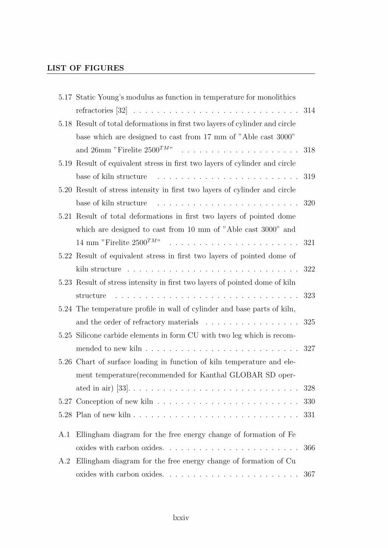
LIST OF FIGURES
5.17 Static Young’s modulus as function in temperature for monolithics
refractories [32] . . . . . . . . . . . . . . . . . . . . . . . . . . . . 314
5.18 Result of total deformations in first two layers of cylinder and circle
base which are designed to cast from 17 mm of ”Able cast 3000”
and 26mm ”Firelite 2500TM” . . . . . . . . . . . . . . . . . . . . 318
5.19 Result of equivalent stress in first two layers of cylinder and circle
base of kiln structure . . . . . . . . . . . . . . . . . . . . . . . . 319
5.20 Result of stress intensity in first two layers of cylinder and circle
base of kiln structure . . . . . . . . . . . . . . . . . . . . . . . . 320
5.21 Result of total deformations in first two layers of pointed dome
which are designed to cast from 10 mm of ”Able cast 3000” and
14 mm ”Firelite 2500TM” . . . . . . . . . . . . . . . . . . . . . . 321
5.22 Result of equivalent stress in first two layers of pointed dome of
kiln structure . . . . . . . . . . . . . . . . . . . . . . . . . . . . . 322
5.23 Result of stress intensity in first two layers of pointed dome of kiln
structure . . . . . . . . . . . . . . . . . . . . . . . . . . . . . . . 323
5.24 The temperature profile in wall of cylinder and base parts of kiln,
and the order of refractory materials . . . . . . . . . . . . . . . . 325
5.25 Silicone carbide elements in form CU with two leg which is recom-
mended to new kiln . . . . . . . . . . . . . . . . . . . . . . . . . . 327
5.26 Chart of surface loading in function of kiln temperature and ele-
ment temperature(recommended for Kanthal GLOBAR SD oper-
ated in air) [33]. . . . . . . . . . . . . . . . . . . . . . . . . . . . . 328
5.27 Conception of new kiln . . . . . . . . . . . . . . . . . . . . . . . . 330
5.28 Plan of new kiln . . . . . . . . . . . . . . . . . . . . . . . . . . . . 331
A.1 Ellingham diagram for the free energy change of formation of Fe
oxides with carbon oxides. . . . . . . . . . . . . . . . . . . . . . . 366
A.2 Ellingham diagram for the free energy change of formation of Cu
oxides with carbon oxides. . . . . . . . . . . . . . . . . . . . . . . 367
lxxiv

LIST OF FIGURES
A.3 Ellingham diagram for the free energy change of formation of K
and Na oxides with carbon oxides. . . . . . . . . . . . . . . . . . . 368
A.4 Ellingham diagram for the free energy change of formation of K
and Na oxides with carbon oxides. . . . . . . . . . . . . . . . . . . 369
A.5 Ellingham diagram for the free energy change of B2O3 and SiO2
with carbon oxides. . . . . . . . . . . . . . . . . . . . . . . . . . . 370
A.6 . . . . . . . . . . . . . . . . . . . . . . . . . . . . . . . . . . . . . 371
A.7 . . . . . . . . . . . . . . . . . . . . . . . . . . . . . . . . . . . . . 372
A.8 . . . . . . . . . . . . . . . . . . . . . . . . . . . . . . . . . . . . . 373
A.9 . . . . . . . . . . . . . . . . . . . . . . . . . . . . . . . . . . . . . 374
A.10 . . . . . . . . . . . . . . . . . . . . . . . . . . . . . . . . . . . . . 375
lxxv

LIST OF FIGURES
lxxvi

List of Tables
1 Caracteristiques et coefficients specifiques utilises pour la preparation
des glacures [18] . . . . . . . . . . . . . . . . . . . . . . . . . . . . xxxvi
2 Facteurs pour le calcul de module de Young a partir de composi-
tions chimiques [19] . . . . . . . . . . . . . . . . . . . . . . . . . . xxxvii
3 Composition en unites de masse qui Doat Taxile utilise pour pro-
duire la glacure cristalline a Sevres . . . . . . . . . . . . . . . . . xxxviii
4 la Ratio de Fe2+ / Fe3+ ,longueur d’onde (λD) et couleur de glacure
pour quelque echantillons de ancienne Ru porcelaine. . . . . . . . xl
5 Calcul du pourcentage de matieres premieres pour la recette de
R47b . . . . . . . . . . . . . . . . . . . . . . . . . . . . . . . . . xli
6 Les valeurs calculees des proprietes mecaniques en email de porce-
laine et le corps de Ru porcelaine . . . . . . . . . . . . . . . . . . xlii
1.1 composition% en masse of soft-paste porcelain at Saint Amans and
Aikin . . . . . . . . . . . . . . . . . . . . . . . . . . . . . . . . . 35
1.2 Composition % en masse of glaze to soft-paste porcelain at Saint
Amans . . . . . . . . . . . . . . . . . . . . . . . . . . . . . . . . 35
1.3 Composition en unite of masse which Taxile Doat used for produc-
ing the crystalline glaze at Sevres . . . . . . . . . . . . . . . . . . 51
3.1 Characteristics and specific coefficients used for glaze preparation[18]182
lxxvii

LIST OF TABLES
3.2 Factors for calculating Young’s modulus from chemical composi-
tions [19] . . . . . . . . . . . . . . . . . . . . . . . . . . . . . . . . 185
3.3 The Fe2+ / Fe3+ ,wavelength (λD) and glaze color for some samples
of Ru kiln . . . . . . . . . . . . . . . . . . . . . . . . . . . . . . . 192
3.4 The Fe2+ / Fe3+ ,wavelength (λD) and glaze color for some samples
of Guan glaze . . . . . . . . . . . . . . . . . . . . . . . . . . . . . 193
4.1 Main chemical oxides of Ru Guan porcelain body (RGPD) . . . . 208
4.2 Calculated values of different properties for Ru porcelain bodies
samples . . . . . . . . . . . . . . . . . . . . . . . . . . . . . . . . 211
4.3 Main chemical oxides of Ru Guan glaze . . . . . . . . . . . . . . . 213
4.4 Calculated values of different properties for Ru glaze samples) . . 216
4.5 Calculated values of mechanical properties in glaze and porcelain
body of Ru Guan kiln . . . . . . . . . . . . . . . . . . . . . . . . 218
4.6 The chemical composition of kaolin d’Arvor . . . . . . . . . . . . 220
4.7 Calculating the percentage of raw materials for batch recipe of
Pemco Frit P-54, see appendix (A.0.8). . . . . . . . . . . . . . . . 234
4.8 Calculating the percentage of raw materials for batch recipe of
glaze that is used for thermal shock treatment . . . . . . . . . . . 235
5.1 The required data to simulate the total deformations,equivalent
stress and stress intensity in two parts cylinder and base . . . . . 316
5.2 The required data to simulate the total deformations,equivalent
stress and stress intensity in dome part of kiln . . . . . . . . . . . 317
A.1 chemical analysis for some clay bodies from Iraq which are covered
by luster metallic expressed in oxide percent and normalized to
100%. . . . . . . . . . . . . . . . . . . . . . . . . . . . . . . . . . 343
A.2 chemical analysis for some clay bodies from Kairouan which are
covered by luster metallic expressed in oxide percent and normal-
ized to 100%(∆is the standard deviation ) . . . . . . . . . . . . . 344
lxxviii

LIST OF TABLES
A.3 chemical analysis of glazes with metallic reflection from Kairouan
expressed in oxide percent and normalized to 100%(∆is the stan-
dard deviation ) . . . . . . . . . . . . . . . . . . . . . . . . . . . . 345
A.4 chemical analysis of Iraq luster metallic glaze expressed in oxide
percent and normalized to 100%. . . . . . . . . . . . . . . . . . . 346
A.5 chemical analysis of some kinds of wood ,normalized to 100%. . . 346
A.6 chemical analysis of some kinds of lignite ,normalized to 100% . . 347
A.7 chemical analysis of some kinds of coal ,normalized to 100% . . . 347
A.8 classification for oxide glasses based on single bond strength . . . 348
A.9 Temperature equivalents for Orton standard large cones. Source:
American Ceramic Society. . . . . . . . . . . . . . . . . . . . . . . 349
A.10 temperature equivalent for Seger standard cones ,source: Staatliche
prozellan-manufaktur, Berlin . . . . . . . . . . . . . . . . . . . . . 350
A.11 A Cross Reference List Of Comparable Frits . . . . . . . . . . . . 351
A.12 Standard glaze frits in order of Fusion temperature from Ferro
Company ,Composition in Equivalent . . . . . . . . . . . . . . . . 352
A.13 weight fraction of each oxides components of Ru Guan porcelain
body (RGPD) . . . . . . . . . . . . . . . . . . . . . . . . . . . . . 354
A.14 weight fraction of each oxides components of Ru Guan glaze . . . 355
A.15 Calculating the percentage of raw materials for batch recipe of
R47b . . . . . . . . . . . . . . . . . . . . . . . . . . . . . . . . . 359
A.16 Calculating the percentage of raw materials for batch recipe of
R47G . . . . . . . . . . . . . . . . . . . . . . . . . . . . . . . . . 363
A.17 Product Information of dense Concretes FirecreteTM 95 . . . . . 376
lxxix

LIST OF TABLES
lxxx

Introduction
Ceramic, as an art, has interactive relationship between some domains such as
arts, history, and science. Therefore reflecting on the nature of the interactive
relationship between these domains can be a rational intention, in order to create
new prospects for creativity in art and applied ceramics. Normally that creativity
aims at the beauty in art, and this can be occurred basing on the information
which discovered from the history of ceramics, and this depends on the ability of
science represented in the modern technology.
Throughout history, there are many experiences about methods and tech-
niques production of ceramics which have been accumulated, and these expe-
riences are very interesting for everyone who is involved in ceramics especially
ceramists artists. And there are many historical and archeological studies which
try to discover ancient ceramics techniques that are used in art to produce ex-
pressive ceramics art. Therefore Ceramics technology is a multifaceted study
involving the technique of manufacturing pottery and organization of the ceram-
ics industry [34].
Simply the ceramics and pottery are considered as one of the oldest activities
in the history of human societies, and they are related to human civilization,
therefore the developments in the features of human civilization have resulted to
developments in the ceramics productions and its embellishment. All civilizations
were taking care of them everywhere in east or west. However, the quality and
promoted ceramics productions depend on some general factors: the available
1

INTRODUCTION
materials, the known technologies of production, and the Philosophy and concept
of art established, and these factors were developed from place to place and from
one era to another until the modern era in Europe.
Therefore, its aesthetic treatments and qualities were varied from place to
place and from one era to another, And despite the great diversity of aesthetic
treatments applied on the surfaces of ceramics production, but its stages produc-
tion are similar to a large extent. Where the principles stages are:
1. Stage of preparing the clay.
2. Stage of forming the clay.
3. Stage of treatments before the drying.
4. Stage of drying.
5. Stage of primary firing.
6. Stage of applied glazes.
7. Stage of second firing.
8. The stage of treatments after the firing.
The implementation methods of each one of these stages are varied from one
culture to another, also one or more stage can be added or delete to/of them, this
bases on the exitance progress in life, the accumulations of notion in science of
ceramics and experiences in technology of ceramics, and the philosophy of art and
the spirit of beauty. Consequently, the technology has an effective role on evolv-
ing the production of ceramics, and the tools have roles in quality of technology,
and due to the relationship between science and technology where technology is
seen as ”Knowing how” while science is seen as ”Knowing why” [35] ,so the ad-
vancements of science have an important role in the development of tools which
used in producing ceramics. Furthermore, each stage of the producing ceramics
stages has specials tools.
2
INTRODUCTION
There is a strong correlation between the tool and the stage which required
this tool. This correlation comes from correlation between the tool and its func-
tion, and the correlation between the function and the stage of production. This
led to the diversity of plentiful tools in ceramics field. However, the developments
in ceramic require developing in design and production the ceramics’ tools. And
development process colligates with overall stages, and at the end, the devel-
opments appear in forms’ beauty and function of ceramics products.The finale
appearance of ceramics determined during the stage of firing where the clay body
converts from Greenware to Stoneware, glazes recipes convert from fine powder
to shiny glass phase and color oxides change from primary color to final color.
All of these modifications in ceramics production resulted from high temperature
which ceramic materials supposed to, so that some chemical reactions occurred
and some physical properties changed. And this firing stage required kiln tech-
nology.
This firing stage required kiln technology. As kiln technology improved, more
beauty treatments for ceramics and pottery surface increased[22], and also the
construction of glaze was adapted with this kiln technology. . So one may look
kiln as a tool for giving aesthetics treatment to ceramics forms; from importance
of firing process, we can understand how ceramists, over long history, take care of
the firing process and kiln technology. Where the prehistoric pottery was open-
fired .open firing was in surface bonfires or in pits, by this early firing technology
the quality of ceramics forms was imperfect, as a result of low temperature, con-
tacting between the vessel and materials that used as sources of burning and
difficulties during open-firing where it required added sufficiently coarse or the
vessel will explode[36].
When this kiln technology was only available to potters, the vessels decora-
tion was limited to black color which could be exist by smoking during and after
the firing, or limited to some texture treatments by stamping or engraving. And
3

INTRODUCTION
these imperfect quality and limitation decoration urged early potters to originate
the oven-firing where pots fired in temporary or permanent oven made of bricks,
clay or stone[37],and also these reasons with requiring high temperatures urged
early potters to originate firing kiln where it conserve heat better than in case
of open-firing and oven-firing, and decorating by colors need drafting the smoke
and separating the ceramics objects from the flame[37].
After kiln technology had known in the history of ceramics production, there
are a lot of styles of decorating ceramics surface depending on some procedures
during or after firing process like wood-fire glaze, ash glaze, salt and soda glaze,
and oriental glazes all of this glazes need especial atmosphere during the firing
stage and the results of surface beauty are very interesting to many ceramists even
in twenty-one century this adjacent to raku-firing and reduction saggar-firing.
In otherwise there are some of glazes, particularly earthenware (faıence) glazes
containing lead or tin ,are require protection inside saggars, when fired in fuel-
burning kilns. Highly decorated ceramics from Europe like Maiolica, Faıence,
and slipware -Terra sigillata- be in the right place in this category[38]. These
requirements led to improving kiln designs and use muffle section to separate the
combustion gases from the main chamber or main tunnel, also may the develop-
ment of the electric kiln was useful for these oxidation glazes, where heating is
generate from passage electric current in heat coils so there is no fuel burning.
Therefore, searching in history of ceramics and in history of firing technology
we can know more about the effect design of kiln on aesthetic treatment to ce-
ramics surfaces.Also these aesthetic treatments from colors and textures of glazes
are chemical reactions and physical properties occur during the firing. So the
scientific studies to ceramic raw materials and condition of reactions for these
raw materials can be useful for producing some aesthetic treatments by modify-
ing the kiln design. Due to correlation between kiln and firing process, the kiln
design and technology with organizing raw materials are the confrontation to use
4

INTRODUCTION
kiln as a tool for making special aesthetics treatments. Considering kiln as tool
to create aesthetics treatments requires two main things: the first thing is how
we can modify it to control the atmosphere of firing process, the second one is
possibility to modify kiln structure,so we can do experimental treatments during
or after firing.∗ By that modification we can do that:
-Isolate all the factors which have an effect in final appearance to ceramic
during the firing process.
-We can change in one or some of these factors which could modified in final
appearance to ceramic.
So I ask:
-Does the firing process affect in the aesthetic of ceramic forms surfaces?
-Are we able to control that process to produce a new aesthetic treatment?
A history of techniques of ceramic in some civilization can give us evidence
about some firing techniques had affected ceramic surface treatments; it could
help us to understand how we can start modifying kiln structure. Good studies
of chemical reactions in kiln give monitoring, and modifications of the (new) kiln.
Problem of research
The problem of research comes from: Ceramists required modifying their firing
tools, especially it could be play an active role in aesthetic treatments of ce-
ramic surfaces. As it is a tool which provides conditions to chemical reactions
and physical characteristics that are affected in aesthetic treatments of ceramics
forms. So, the problem is determined in design and produce ceramic kiln, which
allow for some experimental treatments during and after firing process to enrich
∗After firing or post firing: that period of time when the temperature of the form came
slowdown to low degree which we can do kind of procedure effect in aesthetics treatments of
ceramics surfaces.
5

INTRODUCTION
the aesthetics treatments for ceramics forms, this kiln provide an influence in
reactions and properties conditions to clay and glaze raw materials.
Aim of research
This research aim to modify firing process to influence the aesthetic of ceramic
forms surfaces by:
- studying designs and structures to some last civilization kilns which there
are affect in the aesthetic treatments to ceramic forms surfaces.
-Studying chemical reactions and physical properties which happened during
firing process or post firing to know what we need in new kiln structure.
Research hypotheses
To exist the aims of research the researcher suppose :
1. The historical study to firing techniques and kilns will indicate the potential
for modify kilns to affect positively in aesthetics of ceramic form.
2. The possibility of doing operations during and after firing to affect posi-
tively in aesthetics of ceramic form.
3. The possibility of modification in designing and building ceramic kiln could
do some processes during or after firing which affect in aesthetics of ceramic form.
Methodology and research procedures
For verify assumptions of research; the researcher will use the historical curricu-
lum, analytical curriculum, and experimental curriculum.
6

INTRODUCTION
I-Theoretical study:
1. Historical study to ceramic kilns and fundamentals designs to these kilns in
some different civilizations
2. Scientific study for chemical reactions and physical properties which happen
during or post firing, and factors are affecting it.
3. Analytical study to different applications which influence aesthetic of ce-
ramics surfaces during firing or post firing.
4. Analytical study to kiln structure and its parts.
II-Experimental study:
This depend on the historical, scientific and analysis studies:
1. Do experimental examples to test the theatrical and history study.
2. Design ceramic kiln could use to firing ceramics forms and could use to do
some experimental treatments during or post firing
7

INTRODUCTION
8

Chapter 1
literature review
This chapter briefly introduces a literature review of correlations between art,
science, history and history of ceramic technology in referring to kiln tech-
nology and firing process. It focuses on the relationships between some discipline
and ceramics,general factors which effect in promotional ceramics productions,
important role of history in ceramics art, and the important role of science to
improve ceramics technologies. Moreover the dynamical relationship between fir-
ing technologies in history and the aesthetic treatments on ceramics surfaces are
mentioned. Conclusions concerning the kiln as a tool deserves attention to enrich
the beauty of ceramics forms.
9

LITERATURE REVIEW
1.1 Relationship between some disciplines and
ceramics
1.1.1 History
The historical studies are related to several domains as result of concerning events
and human activities where history seek to understanding the events and put
it over timeline. For this aims the history use all evidences, the pottery and
ceramic as an oldest applied activity is related to aspects of life from prehistoric,
and ceramics forms are used for a functions and decorations. So ceramics have
important role in history as follows:
a. Where ceramic is evidence which can be used to knowing some information
about trading between civilization and the other where ceramics products have
distinctive features varies from culture to another.
b. Where ceramics are used to indicate about the development societies, where
the improving in ceramics techniques require scientific discovering to prepare raw
materials and achieving high temperatures.
c. Where decoration pattern and style of art which are used to decorate ce-
ramics forms are important to understand the concept of art in some civilizations.
And also history gives very important information to ceramists about:
a. Past technology of ceramics and their tools which are used during history
for producing the ceramics forms. Where historical studies about ceramics tools
and technologies describe the deferent methods of producing ceramic and record
the development in the ceramics technologies and their chronologies.
b. Description of all types and styles of ceramics, also history refer to some
factories and famous trademarks, classification of the bodies and glazes of ceram-
ics, and study of colors and decorations patterns.
Due to this study is concerning to some procedures which occurred during or
after firing which enrich the aesthetics of ceramics shapes; so history of ceramics
10

RELATIONSHIP BETWEEN SOME DISCIPLINES ANDCERAMICS
technology is important to describe some of these procedures, and in otherwise it
helps to understand the methods of producing these style of ceramics and under-
stand the sequence of improving of firing ceramics and put these improvement on
timeline to compare between technical of firing and finale appearance to ceramics
shapes which is the remarkable to every ceramists.
1.1.2 Archeology
Archaeologists studies search in investigation history of groups of people and
understand development of entire culture based on their material and physical
remains to describe and classify artifacts, known the relationships among sites,
and build cultural chronologies [39]. Ceramics and pottery are oldest artifacts;
they have deep roots from prehistory, wherefores they are very important for
archaeologists as a material that can be found in all sites. At the same time the
archeology give notion about:
a. The ceramics materials like: clay, slip and glaze and what is deferent among
these materials from culture to another.
b. The kilns sites and their structure and how and why it was changed from
culture to another.
c. The factories places and their systems of production in addition to discuss
why and how it was improved from culture to another.
Due to this study is concerning to understanding how and why development
of kiln and firing technology changed, and due to we are interested in this study
to knowing evolution of the role of culture, technology and raw materials in de-
termination the beauty of ceramic products and their promotion; so archaeology
studies that pertain to ceramics raw materials, ceramics firing technology, and
kilns sites are important in order to provide us by necessary information to design
the kiln which be used as tool for enrich the beauty of ceramics forms. Addition-
ally, archeology reconstructs the history of cultures and it relies on methods of
11

LITERATURE REVIEW
excavation, survey, sampling, collection, and relative and chronometric dating[39].
So the relationship between history and archeology is considered.
1.1.3 art
Art in contemporary philosophy is a matter of controversy; because there are
many views about what is the art. And for answer this question, and discuss the
concept scientifically, we have to involve in the philosophy of aesthetic and beauty
of art but this is a huge work to do here. this controversy comes from the natural
of beauty of art where is not as external perceptible, it is an inner object , and it
is present to sensation depending on human intuition, so beauty has often been
regarded as purely subjective pleasure, or a merely accidental sense [40]. and
with the modification of human cultures and knowledge also the perception and
awareness are changed , thus the views about what is art are developed. Despite
of this, there was a familiar idea of the work of art, and it determines what is
work of art. These common ideas of art take the three following heads[40]:
a. the work of art is no natural product; it is brought by human activity
b. the work of art is produced for apprehension by men’s senses
c. the work of art has an end and aim in itself
From the beginning, that a work of art is a product of human activity, there
are some points of views are revealed over history to discuses issue of art, and
they considered it as one of human activities, and they discuss how these views
affect the styles of art works. It is important to mention these points of views.
Despite every one of these views have some false aspect but they had effect and
still effect in ceramists’ beliefs about art works of ceramics.
According to these points of views, the relation between ceramics and art
will be known, since ceramics are a human activity and we will discuss these
philosophy views as following:
a. This point of view considered this activity as conscious production of an
external object, it can be known and expounded, and learnt .That in addition
12
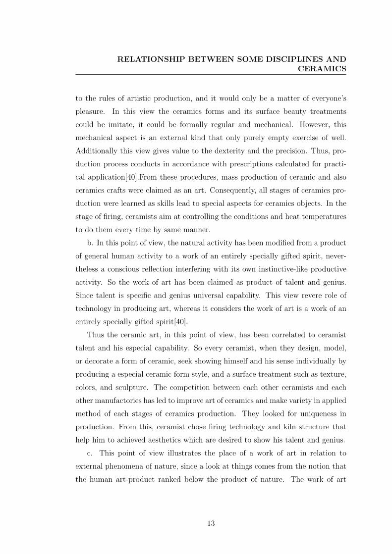
RELATIONSHIP BETWEEN SOME DISCIPLINES ANDCERAMICS
to the rules of artistic production, and it would only be a matter of everyone’s
pleasure. In this view the ceramics forms and its surface beauty treatments
could be imitate, it could be formally regular and mechanical. However, this
mechanical aspect is an external kind that only purely empty exercise of well.
Additionally this view gives value to the dexterity and the precision. Thus, pro-
duction process conducts in accordance with prescriptions calculated for practi-
cal application[40].From these procedures, mass production of ceramic and also
ceramics crafts were claimed as an art. Consequently, all stages of ceramics pro-
duction were learned as skills lead to special aspects for ceramics objects. In the
stage of firing, ceramists aim at controlling the conditions and heat temperatures
to do them every time by same manner.
b. In this point of view, the natural activity has been modified from a product
of general human activity to a work of an entirely specially gifted spirit, never-
theless a conscious reflection interfering with its own instinctive-like productive
activity. So the work of art has been claimed as product of talent and genius.
Since talent is specific and genius universal capability. This view revere role of
technology in producing art, whereas it considers the work of art is a work of an
entirely specially gifted spirit[40].
Thus the ceramic art, in this point of view, has been correlated to ceramist
talent and his especial capability. So every ceramist, when they design, model,
or decorate a form of ceramic, seek showing himself and his sense individually by
producing a especial ceramic form style, and a surface treatment such as texture,
colors, and sculpture. The competition between each other ceramists and each
other manufactories has led to improve art of ceramics and make variety in applied
method of each stages of ceramics production. They looked for uniqueness in
production. From this, ceramist chose firing technology and kiln structure that
help him to achieved aesthetics which are desired to show his talent and genius.
c. This point of view illustrates the place of a work of art in relation to
external phenomena of nature, since a look at things comes from the notion that
the human art-product ranked below the product of nature. The work of art
13

LITERATURE REVIEW
has no feeling in itself and is not completely enlivened. Whereas the alive is an
organism elaborated into all its tiniest parts, a work of art attains the appearance
of life only in its surface. so art is more than aggregate of fundamentals elements
which constitute a work of art ; Here a work of art is originate from the spirit,
belongs to the territory of the spirit, and what has been formed in harmony
with the spirit. Thus work of art is higher than any natural product which has
not made a journey through the spirit. Also living thing in nature is transient,
vanishing, changeable in outward appearance ,while the work of art persists and
its having made spiritual inspiration conspicuous[40].
From this point of view, ceramists aim at decorating ceramics forms and their
surface by natural appearance with spiritual inspiration. In ceramics art, the
ceramist has using some elements to make a journey through the spirit: form,
sculptor, colors and painting, and aspect of metallic. Ceramists have expressed
themselves by these elements on surface of ceramic, and these expressions have to
be permanence. Outward permanence appearance of ceramics forms usually came
after firing. Therefore conditions of firing process effect in outward appearance
of ceramics, so firing technology is important for completing work of ceramic art.
d. According to this point of view, an art work is made by man as creation of
his spirit. Human activity which is a mode of self-production in external things
which is present in work of art and it is not only with external thing, but no
less with himself, and with his own natural figure. Therefore beauty is doing
deliberately alterations in things, in artist himself, and his own natural figure.
Art is required as man’s rational need to lift the inner and outer world into
his spiritual consciousness as an object in which he recognizes again his own
self[40]. Thus, beauty of ceramics forms is a highest aim, and it seems to bring
what is inner ceramist into sight and knowledge for himself and others, which is
in distinction from others actions, since this aim is present in form of ceramic.
However, here the ceramist has started to get spiritual freedom, but that related
to technology of producing ceramics projects where all of ideas will present in form
of ceramics. Recently, ceramists are interesting to create new designs depending
14

RELATIONSHIP BETWEEN SOME DISCIPLINES ANDCERAMICS
on improved technologies of produced ceramics. They improve ceramic body
materials for getting a higher ability for formation and whit color for body, if it
is required in final appearance for design. They improve the glazes structure for
achieving new color and texture could be used in new designs for ceramics surfaces
in way of presenting the creation in work of ceramic art. However, if we are looking
to the technology of firing as process that gives the ceramics form a final outward
appearance, and if we imagine the variety in outward appearances that might exist
by changing the condition of firing process, then the improving of kiln technology
will be considered as tool for enriching ceramics surface artistically, since kiln
technology will be method for creation. In all of these points of views about that
idea which consider the art is a human activity; the technology it was important
for producing art. Therefore where the concept of art was, the technology of
producing ceramics was considered particularly the firing technology.
1.1.4 Science
Science attempt to understand how and why phenomena occur, focus on the
”natural” world, belief in empirical information, value placed upon objectivity,
codify into laws or principles, and test and refine the hypotheses[35]. Ceramics
is an art reliance on working with clays and glazes, since clays are a natural
composed of fine-grained minerals and the main mineral is a ”kaolinite” and its
chemical composition is Al2Si2O5(OH)4 ,also glazes in raw state are composed of
fine-grained and its chemical compositions are written in molecular unity formula
which is called Seger formula . In addition, ceramists need to understand physical
properties of clays and glazes through all stages of producing ceramics particularly
during firing process.
From the considered relationship between science and ceramics, science ex-
plains nature of clay and glaze, understand how and why clays were decomposed
sedimentary from rocks, explain ceramic color, and explain empirical information
about clays and glazes, and influence of heat on clays and other minerals. Design
15

LITERATURE REVIEW
and producing ceramics tools are considered, since it needs to understand the
phenomena that are used for design and to produce this tool. Actually, these
information and methods which are required to improve discipline of ceramic art
related to science, in other word, development in ceramics productions depends on
scientific discovers which are related to ceramic materials, ceramic applications,
or ceramic tools.
So there are divisions of science that look at notion which helps in improving
ceramics technology. Therefore, it is useful to mention the relationship between
science and technology[35].
1.1.4.1 Relationship between science and technology.
Relationship between science and technology prove the direct relevance between
art and science, whereby technology is a process that includes all terms of ”know-
ing how” while science concerned with understanding phenomena and ”knowing
why”, therefore, the information which exist as result of ”knowing why” will
bring achievements in ”knowing how” so as to provide original possibility, easy
performance, rapid performed, and quality of making. Technology is a creation
system beyond the basic of ceramic work, wherefore relationship between science
and technology is important for designing and producing new tools.
Scientist is seen as interested in understanding the principles, while technol-
ogists are seen as interested in making things and invention objects, tools, and
machinesM.Kranzberg and C. Ppuursell define technology as:
”Man’s effort to cope with his physical environment and his attempt to subdue
or control that environment by means of his imagination and ingenuity in the use
of available resources”[35]
From this definition, technology has existed before science and human used
it to shape the physical world, and history of technology had little relation to
science, for men could make tools without understanding why they worked , but
the developers of technology in history refined their methods by learning from
16

RELATIONSHIP BETWEEN SOME DISCIPLINES ANDCERAMICS
other practitioners , observing all aspects of their environment ,and experimenting
. With improvement of science in eighteenth century, technology began to use
more scientific understanding to solve its problems, therefore scientific research
became more important source of new technologies.
”Historically, technological research is considered somehow less ”pure”, and
less lofty than science. The origins of these attitude lie deep in history of western
culture. Among the Egyptians and the Greek, fabrication was done by slaves or
low artisans.”[35]
With the 18th century in Europe, when many people began to emphasize the
importance of science and reason, the attitude toward technology became positive
and the interplay relationship between science and technology had established.
As Francis Bacon considered that science has to be useful in developing tech-
nological innovation, and he mentioned to attempting to manipulate the nature
technologically, for understanding it clearly[35]. and he suggested that the re-
organization of knowledge and science is important to produce ”a line and race
of inventions that may in some degree subdue and overcome the necessities and
mysteries of humanity”[41].
In the 19th century, this relation became completely grown with the establish-
ment of ”Ecole Polytechnique” in France, Germany, and technical school later in
United State. These universities aimed to apply science into technology, and they
played a most important role in expansion of technology at the end of century
, and that was existed by using science to solve technological problems rather
than to advance knowledge [42] In Europe, pottery making transformed from
peasant craft to sophisticated industry ever since the relation between ceramic
technology and science was established, and with experimentation to reproduce
Chinese hard-paste porcelain. By this imitations there are many soft paste were
given as well as the beautiful delft ware which produced for first time by German
chemist J.F.B?ttger, it was in 1710 , at royal factory was set up at Meissen (near
Dresden) in Saxony.
17

LITERATURE REVIEW
At the French Nat. manufactory Sevres second hard porcelain was produced
in 1768 by P.-J.Macqure chief chemist in Sevres [43] in this era which is consider
a period of emerging transformation pottery to fine ceramic relation between
technology and science was achieved at all famous factories in Europe by role of
chemists to imitate hard-past porcelain . From relation between ceramic technol-
ogy and science, new aesthetical applications for fine ceramics was appeared, and
it have include new past for clay body , new glazes ,and new method for firing
and kilns.
1.1.4.2 Relationship between science research and art.
The relationship between science and art is modified over history as a result of
exchanging between philosophies, where science and art were united before Re-
naissance, when artist was likely to be the person who had wisdom and a good
observation. But with beginning of Renaissance a specialization was established
in the West. Science was arranged as a segregated set of processes and world-
views while art moved in its own direction, ignoring the agendas of science. From
the beginning of industrial revolution, science has inspired technology more than
art[35]. Despite the divergence between science and art since the Renaissance,
nevertheless there are some relations between them that could explain the im-
portant role of materials and technology in arts, especially ceramics.
As designer’s ideas are embodied in physical entity which is raw materials.
The artist’s ability to present the concept of work with aesthetical appearance
comes from his ability to control and subdue materials. So science helps artists
to accomplish these requirements. Due to a concept of artworks stem from the
vision of artist, and the artist is the most one who realizes his requirements, and
due to part of these requirements related to understanding properties of materials
.wherefore the relationship between science and artist’s necessities led to enriching
the artistic vision and aesthetic treatment. Where, it enhances artists’ ability for
embodying the artistic vision.
18
ALEXANDRE BRONGNIART (1770-1847)
With more reflection on relationship between art and science, we find that
it includes a direct relationship that is to develop tools, technologies, and ma-
terials which are required for artistic production. Where artists search into new
capabilities, and we find also that it includes an indirect relationship, which is
illustrated by science influence on life, thought artist, and human culture.
1.2 Alexandre BRONGNIART (1770-1847)
M.BRONGNIART has revitalized the porcelain manufactory at Sevres, after he
become the director in 14 may 1800 and remained so until his death in 1847.
This revolution in the factory was due to the ability of Brongniart to achieve the
correlation between art ceramics and other disciplines. Where, he was chemist
and mineralogist, and he was cultivated to understand the neoclassical esthetic.
So, he wrote many treatises on mineralogy and the ceramic arts. Brongniart
study many ceramics samples of different culture which was necessary for creat-
ing ceramics museum , and he presented more of historical technologies, and he
developed the technology of firing as well as color preparation after his traveling
in Europe for this reason[44, 45]. The birth and upbringing of Brongniart in
artistic home are affected in his attentions to art and science. He was born in 2
February 1770, and he grown up with wearing course to art and chemistry where
his father was the fumes architect Alexandre-Theodore Brongniart (1739-1813),
and his uncle was the fumes chemist Antoine Brongniart [46]. Brongniart’s fa-
ther was architect and decorator. He became member of France’s Academie des
Beaux-Arts in 1781[47],and he designed and drew numerous famous sites in Paris
such as palais de la Bourse[48],and Boulevard des Invalides [49].
So, Alexandre Brongniart has owned a variety of experience about art ac-
cording to career of his father, and his experience about science was promote
by means of his first chance of success in natural history in 1779 to instruct the
course of natural history at the Central School (l’Ecole centrale), in France, also
19
LITERATURE REVIEW
after working as a mining engineer in 1794 [50]. When he was 30 years, he was
appointed by the First Consul to be director the Manufacture de Sevres , due to
surely through his treatise on (L’Art de l’emailleur) the art of enameling (1791)
and its relationship with Claude Berthollet, who recommended him because he
saw Brongniart as a man combining interest in art and chemistry expertise.
In order to understand how Brongniar was chosen to position of director of
the Sevres Porcelain Factory, the great change in political of France coincided
with emergence of Brongniar in scientific activities. Where, the political changes
were linked to scientific adventures and technological evolution. Thus the progress
through science and its relation with politic necessitated to find new administrator
and to provide instruction. Chemistry played an important role in applied fields
at this period, so the scientists was sat on the Comite de salut public (Public
Health Commission), and the Ecole centrale des travaux publics was established,
and later it become the Ecole polytechnique which aimed to qualified the students
in general scientific training and refining their qualification in specialized schools
such as Ecole de Mines. In this period, the Ecole polytechnique was assigned to
train the military for short time and civil engineering for long time.
Alexandre Brongniar participated in this mission and he wrote ” I was part of
the corps des Mines before the existence of Ecole polytechnique”[21]. Alexandre
Brongniar was the person who has a background that combines between sci-
ence and art, therefore, appointed him to revitalize the porcelain manufactory at
Sevres was logical, especially he was close to political circles. In 1807 he pub-
lished his work ” Traite elementaire de mineralogie, avec des applications aux
arts” (Elementary treatise of mineralogy with application to arts). The breadth
of Brongniar views between art and science was clearly presented in this work.
He illustrated the correlation between theoretical information of science which
involve in ” Knowing why” and applied technologies which involve in ” Knowing
How”, where the investigate new processes and mechanical inventions interested
him and he traveled to numerous country to gather suitable objects for colloca-
tions of museum, as well as he attended scientific congresses. During this travels,
20

ALEXANDRE BRONGNIART (1770-1847)
he succeeded to make others mineralogists tended to objects that give him ad-
vantage, and he succeeded to make them more cooperative with his requests for
access, information and samples. Brongniart, during his trips, made extensive
records of all things that he thought they are important for improving manufac-
tory, where he was interested to past-making materials, technologies and capacity
of kilns, and he drown sketches of tools and kilns, and he given particular atten-
tion to new ideas in fabrication methods and history of ceramics[21].
He visited London from 23 September to 26 October 1802, and after his re-
turn to Paris, the Wedgwood’s famous and fashionable ”black basalt” ware was
successfully simulated [51], this mentions that Alexandre Brongniar’s experiences
in mining, art and science helped him in transfer technologies and find alternative
local raw materials to imitate and improve styles of ceramics which interested him
in his travels. In 1812, Napolion sent him to visit manufactory of porcelain and
workshops and kilns in German, where he aimed to learn about firing technolo-
gies in Berlin which was different from those at Sevres and also about kilns that
used less fuel in Bohemia[52]. In 1820, he traveled to Italy, from there he brought
plat of porcelain and fine earthenware from Vicenza and le Nove . In Venice, he
was attended to the soft-past porcelain which was produced by Cozzi factory. In
1824, the secretary of the academy of Sciences in Stockholm invented Brongniart
to Sweden. During this travel, he vistaed the royal manufactory in Copenhagen
and he brought, from there, fourteen pieces of hard-paste porcelain decorated by
blue underglaze color. In Denmark, he selected some black pottery which was
given a hight luster by burnishing. In Sweden, he visited the Rorstrand factory
and he obtained fourteen pieces of fine earthenware which used there and they
have a typical rang of ground colors. Between 1835 and 1836, he planned to visit
Rhine in Belgium and Holland where the ancient production of faıence, and to
visit Strasbourg, Mayence and Stuttgrt. He selected glassware which were rich
colors, and plate with ridged color from Frankfurt and Bonn, and he obtained
teacup produced at Gotha factory which is decorated with a view of Bonn [21, 53].
21

LITERATURE REVIEW
He had made numerous travels, varied between London, Staffordshire, Berlin,
Dresden, Bohemia and Bovaria. The members of Royal Society helped him to visit
the Staffordshire ceramics factories, and in London, he attempted to get an idea
of the character of porcelain, earthenware, and stoneware products. He examined
the Warceshar porcelain at the request of Reverend W. Buckland a professor of
mineralogy and geology who combined him during this travel in London. Also,
he was interested to some samples of raw materials which he taken them from
Thomase Grainger, where they confirmed that the English use of crushed bone
in their past. He continued in his trip plan to visit Stonebridge in Birmingham
to get idea about its stoneware factory. In Wood factory in Burslem, he admired
the large quantities of production, and he visited Furstenborg factory to review
the recent advances there. Then he traveled to Berlin, and the director of Royal
Porcelain Manufactory, Christoph Georg Frick, received him warmly. In Meissen,
Brongniart got the chance to examine the new machine for shaping plats [21].
Brongniart during these travels discovered many technologies and necessary
information to create the new direction to the porcelain manufactory at Sevres
under transferring scientific and historical information to applicable technology to
produce art of ceramics. He focused in to important things the kiln and available
materials. He decided to improve Sevres porcelain paste to became the superior
to that of Paris, and to be less expensive, easier to work, less subject to damage
in firing, receptivity to colors and gliding, allowed for better glazing, whiter, more
resistant to changes in temperature, and producing edges and relief details that
were finer. Brongniart emphasized that the physical properties of materials were
important in improving quality of paste as there compositions [21].
He reproduced painted and background colors such as ultramarine blue which
was imitated of that from Vienna, and green of chrome. while the gliding was
applied by using gold with sulphate of iron or mercury and after firing it polishing
by agate to make difference effects of polish and mate surfaces of gold color [54].
22

ALEXANDRE BRONGNIART (1770-1847)
Also, modifications of kiln technologies were taken in account, where Brong-
niart recognized from his trips the importance of firing process in improving
sophisticated ceramics. He attended in measuring the accurate temperature of
firing as possible, thus several test pieces were placed inside the kiln each firing
[7]. In 1842, he organized new construction of kiln. He preferred wood as fuel
instead of coal and peat.
The produced works, while Alexander Brongniart was director of the manufac-
tory, were divided to a decorative works such as elaborate vases and centerpieces,
and to functional works including different types of table services pieces. New
forms were added to works productions such as zarf, a kind of cup holder variety
of drawings of ornamental patterns were explored in this period. Many artistes,
architectures and designers were included in the manufactory team to enhance
the esthetics values of produced works. Brongniart’s father designed the particu-
lar vase called ”Jasmin”,the figure (1.1) show the sketch of this vase. The form of
this vase was among the first created in this period. Alexander Brongniart sent
to Alexandre Evariste Fragnored, in 1815 the details of memo which was received
from duke of Saxony-Gotha to request design and produce a small coffeepot with
Turkish form, impressed earthen russet ground, dark brown, to contain only two
cups and he request it with bronze handles gilded. Figure (1.2) shows the sketch
of this coffeepot.
After Fragnored design the coffeepot, Brongniart sent the proposed pieces to
the duke, who resent the drawing with some comments. The formes of coffeepot
have done immediately by Charles-Antoine. Three Theiere ’Turque’ teapots were
presented for sales in 18818, one of them was sent to the duke. He was invented
to produce some decorative vases withe some others smaller and sampler for the
curt of kiln Louis-Philippe, research about sophistication of historical ceramics
suggested several programmes of decoration, in this programmes Jean-Charles
Francois Leloy designed the ”Jasmin Cornet”. Figure (1.3) show the sketch of
this famous vase [21]. From Brongniart history with the porcelain manufactory
at Sevres, it was notable that his experiences in science, history, mineralogy and
23

LITERATURE REVIEW
Figure 1.1: Design and decoration for a vase called ”Jasmin” which was designed
by Alexandre-Theodore Brongniart, Paris 1801, at Sevre factory[21].
24
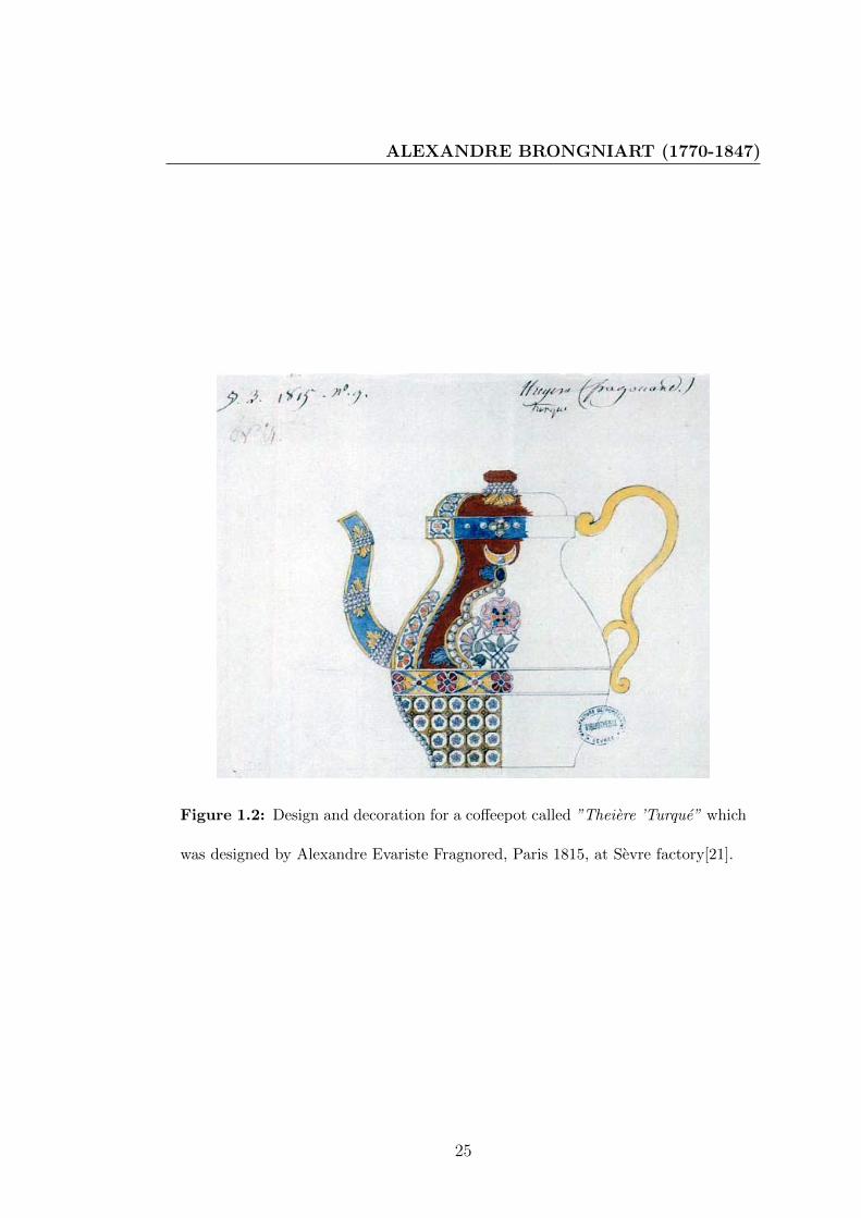
ALEXANDRE BRONGNIART (1770-1847)
Figure 1.2: Design and decoration for a coffeepot called ”Theiere ’Turque” which
was designed by Alexandre Evariste Fragnored, Paris 1815, at Sevre factory[21].
25

LITERATURE REVIEW
Figure 1.3: Design and decoration for vas called ”Jasmin Cornet” which was
designed by Jean-Charles Francois Leloy, Paris 1835, at Sevre factory[21].
26

MANUFACTURE NATIONALE DE SEVRES
art played important role to develop the production process, where he applies
his scientific knowledge to discover more sophisticated clay and porcelain body,
glazes, colors, kiln technologies and gliding. His father helped him to develop
appropriates designs, and he asked new designs from many architects, artistes.
In addition to the role of political that helped him to get information about
historical and modern technologies from different countries that he visited to
collect pieces for national museum of ceramics at Sevres. The accomplishments
of Sevres Porcelain Manufactory under Brongniart’s meticulous direction were
evidence of correlation between some disciplines and ceramics production.
1.3 Manufacture nationale de Sevres
As for the Manufacture nationale de Sevres is of great importance in the history
of the evolution of porcelain, especially in Europe, could indicate the relationship
between science and art of ceramics from history of this factory. It is located in
Sevres, France and the manufacture was successively over the political in France,
where it was a royal factory, imperial and then national. It was also distinguished
in the adornment by gilding. Since 1740, it was still in activity, manufacturing
continues to editing objects created. Its production is largely geared towards
the contemporary today, and it became in 2010 the city of ceramics, with the
National Museum of Ceramics.
In 1740, the Manufacture de Vincennes was established with the support of
Louis XV and Madame de Pompadour, to compete with productions of Meissen
and Chantilly. In this year, the ancient carpenter who is called Claude-Humbert
Gerin discovered that by adding calcined alum in the frit to obtain perfect porce-
lain. This discovering was used for expansion in the construction of factory. In
1746, the kiln of clay body and glaze was improved, as well as the tunnel kiln
for firing decorations colors. In 1748, some recipes of porcelain body, glazes and
gilding preparation were bought for improving the quality of productions[55].
27

LITERATURE REVIEW
In August 1756 the factory was transferred to Sevres in a building built at
the initiative of Madame de Pompadour, near his castle of Bellevue. In 1759,
Louis XV had given his permission to operate the factory at his own expense,
under the supervision of Minister of State Leonard-Jean-Henri Bertin, the Com-
missioner Courteille, the director Jacques-Rene Boileau and chemist Jean Hellot
who was assisted by his colleague Pierre-Joseph Macquer. Therefore the produc-
tion process had grown steadily. In this period the factory Interested in Saxon
and oriental decorations as shown in figure (1.4) , the Vaisseau a mat which
created in 1757 with remaining the style of baroque[55].
The most important event which shows the relationship between ceramics and
scientific experimentation in history of Manufacture nationale de Sevres is the de-
velopment of hard porcelain, since the factory has looked to improve properties
of porcelain body. The identification of components was the main challenge. The
kaolin which was the main component in producing this kind of porcelain was
discovered at Saxe regain in Germany, in 1709 . Gerin and his assistant Gravant
had used kaolin from Belgium; the factory had sought to acquire some secrets for
modifying the properties of porcelain body by buying them from foreign. Mac-
quer had made numerous experiments on French clays. In 1764, a polemic arose
between Comte de Brancas-Lauraguais and the chemist Guettard for discovering
the kaolin in France and producing the hard porcelain. The results which reached
by Guettard was send to research about kaolin in all regions in France by Bertin
, and the chemists and geologists including the Archbishop of Bordeaux in 1767
were involving in this research. This interest has led to discovery of a mine of raw
kaolin which led to improvement in the qualities of products but also it required
modification in production processes. It was required the modification of kiln to
achieve the high temperature as well as the glaze and colors recipes[55].
The factory was passed by difficult period during the French Revolution. De-
spite all difficulties, the increasing shortage of raw materials, timber and gold,
the factory never ceased to produce or to innovate. This period was followed by
28

MANUFACTURE NATIONALE DE SEVRES
Figure 1.4: vaisseau a mat is used as potpourri of Madame de Pompadour, made
of soft-porcelain , Sevres Manufactory, Paris museum Louver (inv. OA 10965)
29

LITERATURE REVIEW
the direction of Alexander Brongniart from 1800 to 1847, and in this period the
factory was flourished as mentioned in section (1.2).
During the period of the Second Republic, the chemist Alphonse-Louis Sal-
vetat with Ebelmen analyzed the Chinese glazes, and the results of this research
were reflected in the aesthetic aspects of sample forms (vases Ly, Bertin). Figure
(1.5) show Ly vase. The name of this very simple form of inspired original Chinese
is a tribute to R.P. Joseph Ly, who sent to Sevres en 1844 a report on manufac-
turing processes and decoration of Chinese porcelain. This style was depended
on translucency properties of porcelain body with transparent glaze, where in
high temperature firing degrees of translucency of porcelain body differed as a
function of its thickness.
Victore Regnault was the director of factory during the period of Second
Empire after Brongniart and who was also an engineer in Mines. In this period
the steam engine was used for preparing the powder and moving the wheel of
forming. Also, the fuels of firing and pyrometric measurements were improved.
The chromolithograph was used as method to apply the decorations.The factory
under the direction of Theodore Deck improved the ability of forming porcelain
clay and permitting to direct work in engraving or relief[55].
Manufacture nationale de Sevres produced four types of different porcelain.
The first is the hard-porcelain (pate dure) ,it is riche of kaolin and relatively
refractory and it used to produce pieces of table service. It is fired at 1400 C.
The second is the Pate Nouvelle , it used for biscuits and to produce objects
that are to be decorated with bright colors . It was fired at 1280 C. The third
soft-porcelain (Pate tender) is used to reproduce the ancient objects and also it
can be exploited in contemporary objects. The fourth is (Pate Antoine d’albis),
it is characterized by white color and it is fired at 1400 C[55].
The relationship between science and art pottery, which was exploited in the
factory also helped in improvement of glaze and colors palette which is used to
decorate the objects of ceramics. The gilding is one of most important decoration
technologies that the Manufacture nationale de Sevres used it brilliantly and in
30

MANUFACTURE NATIONALE DE SEVRES
Figure 1.5: Vase Ly 1850 , Sevres Manufactory, Paris museum Louver MNC(inv.
4178-2)
31

LITERATURE REVIEW
a distinctive. The technique of gilding to soft porcelain depends on mechanical
preparation by gridding for long time, but for the hard porcelain it is depends
on chemical dissolution of gold by aqua regia and then the iron sulfate (FeSO4)
which isolates gold from its solvent[55].
From the history of Manufacture nationale de Sevres, it was demonstrated
that the sceince of ceramics and its history are important in identification the
point which should be followed to enrich their esthetic treatments.
1.4 General Factors Which Affecting the Pro-
ductions of Promotional Ceramics
Quality and promotion of ceramics, throughout history, differed from country to
country and from one century to another, due to a level of progress of civiliza-
tion and cultural in a country during such century play important role in these
differences.
There are general factors that can be considered as influential in the advance-
ment of product of Ceramic. We will discuss these factors as following:
1.4.1 available materials
rmation Purity of raw material as well other materials that are partially treated by
some chemical or physical methods and further materials that are fully prepared
in the laboratory used naturally and its availability effect in the quality. Therefore
potters have given their attention to scientific research about materials since 1710
AD for production of soft-paste porcelain, bone-china, and hard-past porcelain in
Germany, England, and France and they used the alabaster or marble as fluxing
agent, and bone-ash as ingredient. Where quality of clay body became finest in
color, hardness, and translucency, as illustrated in Figure (1.6) and Figure(1.7),
32

GENERAL FACTORS WHICH AFFECTING THEPRODUCTIONS OF PROMOTIONAL CERAMICS
Figure 1.6: Biscuit,soft-paste porcelain (porcelaine pate tendre), Height : 168
mm,designed by E. M. Falconet, Paris 1760,at Sevre factory
[57].
these ceramic bodies were required for improving surface decorations more than
common pottery, and their composition as Brongniart mention in table n (1.1)
[56].
33

LITERATURE REVIEW
Figure 1.7: Biscuit, hard-paste porcelain ( porcelaine pate dur), Height :
220 mm,designed by P. L. Cyffle, France, 1775,at Niderviller factory,A&V mu-
seum,London Nbr: C367-1983
34

GENERAL FACTORS WHICH AFFECTING THEPRODUCTIONS OF PROMOTIONAL CERAMICS
Table 1.1: composition% en masse of soft-paste porcelain at Saint Amans and Aikin
Saint Amans N 1. N 2. Aikin N 3.
Cornish clay
Kaolin argileux
11 41 Cornish clay
Kaolin argileux
31
Ball clay
Argile plastique
19 00 Cornish stone
Kaolin caillouteux
26
Flint
Silex
21 16 Flint,
Silex
2,5
calcium phosphate or ”bone ash”
Phosphate de chaux des os
49 43 calcium phosphate or ”bone ash”
Phosphate de chaux des os
40,5
The composition of glaze which used for covering Saint-Amans biscuit soft-
paste porcelain is in table n (1.2)[58]
Table 1.2: Composition % en masse of glaze to soft-paste porcelain at Saint Amans
Composition N 1.
Feldspar Feldspath 48
Flint or Sand Quartz Silex ou sable quartzeux 09
Uncalcined Crude Borax Borax brut non calcine 21
Frit-glass Verre cristallin 49
So materials have a role that considered as a fundamental in development of
aesthetics of ceramic shapes. Raw materials, synthesizing special recipes which
35

LITERATURE REVIEW
Figure 1.8: Vase ” avec des cygnes ” Soft-paste porcelain. In 1766, at Sevres
factory, louvre museum, purchased 1985 OA11024
compose from these materials, and knowing properties of these materials are used
to applying specific aesthetics. Thus these aesthetics are useful for design and
produce ceramic shapes. Due to the practical actions of ceramics production pro-
cess, green-ware shapes should be treated by heating or firing condition which
led to change in chemical and physical properties, and these changes determine
a final appearance of ceramic forms.
Therefore choosing materials and firing condition are an aesthetical treat-
ment for ceramics surface. There are many aesthetic treatments that have been
enriched by attention to make many experiments and researching on materials
available, and Figure (1.8) shows aesthetic treatments that resulted from these
experiments in the eighteenth century in 1766 at French state manufactory at
Sevres. Where this vas had been decorated by two mains background colors
which are whit and navy blue (bleu fonce)with two another colors for decoration
36

GENERAL FACTORS WHICH AFFECTING THEPRODUCTIONS OF PROMOTIONAL CERAMICS
and painting, which are gild and gray.
• Whit color (N 2∗. Blanc fixe) was produced in the eighteenth century at
Sevres with this composition:
53% of white silica sand Sable blanc d’Etampes, 26% of calcined mixture
that compose of 15 unit of Tin for 100 unit of lead calcine a 15 d’etain pour
100 de plomb , and 21% of Potassium carbonate carbonate de potasse .[58]
• Composition of navy blue color is:
61% of frit Fondant gris n 2∗.which compose of (66.66% of Minium †, 22.22%
of white silica sand sable d’Etampes, 11.11% of melted borax borax fondu),
13% of Cobalt Carbonate carbonate de cobalt, and 26% of zinc carbonate
hydroxide carbonate de zinc hydrate.[58]
• Composition of gray color is:
20% of Gris n 12∗.which compose of(68% of frit Fondant gris n 2∗.which
compose of (66.66% of Minium †, 22.22% of white silica sand sable d’Etampes,
11.11% of melted borax borax fondu), 25% of blue n 28 T∗ which compose
of(79% of frit Fondant gris n 2∗.which compose of (66.66% of Minium †,
22.22% of white silica sand sable d’Etampes, 11.11% of melted borax bo-
rax fondu),7% of Cobalt Carbonate carbonate de cobalt ,and 14% of zinc
carbonate hydroxide carbonate de zinc hydrate),25% of frit june n 41.B∗
which compose of(81% of frit Fondant gris n 2∗.which compose of (66.66% of
Minium †, 22.22% of white silica sand sable d’Etampes, 11.11% of melted bo-
rax borax fondu), 12% of potassium antimonate antimoniate de potasse,6%
∗this code refre to codes that are used in Sever†Lead tetroxide, also called minium, red lead or triplumbic tetroxide, is a bright red or
orange crystalline or amorphous pigment. Chemically, red lead is lead tetroxide,Pb3O4, or
2PbO.PbO2
37

LITERATURE REVIEW
of zinc carbonate hydroxide carbonate de zinc hydrate, 1% of ferric oxide
oxyde de fer par l’eau ),and 30% of zinc carbonate hydroxide carbonate de
zinc hydrate .[58]
.
The process of gilding require some materials like gold chloride, aqua regia
for dissolving gold ,sulphate of the protoxide of iron ,bismuth oxide , borax, and
spirits of turpentine[59].
Therefore materials were an issue important for creating many colors and
surface treatments to decorate ceramics forms, and some of glazes recipes require
special circumstances in firing process.
1.4.2 Production Technologies
For producing ceramics forms, materials should be influenced by some circum-
stances that led to change in physical or chemical properties, and this change is
responsible about final appearance of ceramics products. Physical and chemical
change related to stages of production, and perfection of producing process de-
pends on technology that used to prepare or form ceramic materials over stages
of production.
The final appearances to ceramic forms reflect a point of view of one of ce-
ramists, and we can imagine how the technique which be done to produce ceramics
forms is important to get shape and color exactly. We can describe the technique
used in the final appearance.
∗this code refre to codes that are used in manufacture nationale de Sevres†Lead tetroxide, also called minium, red lead or triplumbic tetroxide, is a bright red or
orange crystalline or amorphous pigment. Chemically, red lead is lead tetroxide,Pb3O4, or
2PbO·PbO2
38

GENERAL FACTORS WHICH AFFECTING THEPRODUCTIONS OF PROMOTIONAL CERAMICS
So, creation of new technique is important to give ceramists more ability to
express their viewpoints, especially if they couldn’t produce by traditional tech-
nique. It is also taken in account for artist’s viewpoint.That technical importance
is identical in applied arts, and in fine arts, where changing technique will give us
variety in aesthetic treatments as fine artists need it. Also controlling elements
of technique could give us same treatments for mass production.
So tools and machines which are used in production process are very important
to perfect the performance of ceramists for producing ceramic forms with high
quality and with especial aesthetical decoration. Tools are varied from stage to
another in ceramics productions. There are tools for preparing materials, for
forming shapes, for firing, and for applying some treatment after firing.
Tool is linked to the function of performs, and it is linked to one of the stages
of production, and this relationship becomes a close relationship between the tool
and the stage at which it is used and that diversity and multiplicity of tools in
the field of ceramics. Developments in the field of ceramics require a development
of production tools. The evolution is linked to all stages and it appears in form
and function of ceramic products. Here it is brought to mind that all steps are
linked and they are separated only for specification study. In firing stage, all the
chemical reactions taking place with some impact on the aesthetics of ceramic
form. Therefore it could be a stage qualified to doing some procedures that could
be used for enriching ceramics forms aesthetically in this research.
1.4.3 Philosophy and Concept of Art
The concept of art is controversial issue in philosophy. Every artist especially
ceramist tends to believe in one of philosophies of art and he is convinced of one
concepts of art, so he translates this concept in his artworks, and ceramic forms,
and chooses between techniques and also chooses suitable materials for applied
art works matching with his viewpoint about aesthetic.
39

LITERATURE REVIEW
1.5 Important Role of Science in Ceramics Art
Science have important role in improving our techniques of applied arts and fine
arts, and this is the base that this research stroke and discuss. It appears clearly
in ceramics and pottery, ceramists grapple with chemicals reactions and physical
properties of clay and glaze. Where science help in classification raw materials,
discuss their chemical composition, and discuss their physical properties.
These chemical reactions and physical properties are inherent to high temper-
ature (Firing process), and they have main role in determined final appearance
and surface treatment to ceramic form. If the chemical reactions and physical
properties, which happen in firing process, are responsible of final appearance and
aesthetic treatment to ceramics forms, ceramist can imagine that changing condi-
tions of these reactions and properties are a good way to achieve new treatments
for ceramic surface beauty.
Where science provides us by expectations about reactions that could happen
during firing process, also it could guide us to prepare a certain circumstance that
make an especial reaction to take place on surface of ceramics, and these especial
reactions lead to especial aesthetical treatments. As well as science has functional
role in calculating the glaze recipes from converting a formula to an analysis and
vice versa. In addition, science has a useful role in modifying quality of forming
clay, quality of glaze and color painting over or under glazes , and condition of
firing.
1.6 Important Role of History in Ceramics Art
Pottery has deep roots in human history, so history of technique guide us in
this research, where it provide the details about types and styles of ceramics
forms which required any treatments during or after firing process , and these
treatments obligated to make a special aesthetic appearance . These historical
40

IMPORTANT ROLE OF HISTORY IN CERAMICS ART
Figure 1.9: A Flow chart show relationship among Science, art, and history
techniques are desirable treatment especially with creative as a concept of art.
Contemporary ceramists interest the traditional firing methods, as a result of
its ability to make variables and individuals aesthetical treatments. Figure (1.9)
shows the role of history in ceramics art.
Where it show how history reserve information about prehistoric and tradi-
tional pottery and ceramics techniques. History of ceramics technologies is used
by artist for producing modern ceramics art. Additionally, history involve in
discovering obsolete prehistory technologies and neglected techniques, so repro-
ducing these techniques are useful to creating modern ceramics art as Figure
(1.10) show a ceramic artwork was created by Linda Keleigh in 2003,it is a bur-
nished terra sigillata;that is fired by barrel-fired reduction with wood, sawdust,
pond grasses, and copper carbonate [60].
41

LITERATURE REVIEW
Figure 1.10: Ceramic artwork (Orb, 2003) created by Linda Keleigh
The technique was used to produce this artwork depended on prehistoric firing
technique which called pit-fire, the ceramist improve this technique by reviving
the traditional technique, but this exists with modifying some materials, appli-
cation and tools. These modifications come from accumulation of knowledge and
discoveries in science and it aim at enriching modern ceramics art aesthetic and
art.
Therefore, history of techniques of ceramic in some civilization can give us
evidences about some firing techniques, which had affected ceramic surface treat-
ments; it could help to understand how ceramics aesthetic can be enriched by
certain treatments during or after firing process, and by modifying kiln struc-
ture. When these evidences are studded within a framework of new science and
new technologies, it led to new prospects of creativity.
42

CORRELATION BETWEEN KILN TECHNOLOGY AND FINALEAPPEARANCE OF CERAMIC FORMS
1.7 Correlation Between Kiln Technology and
Finale Appearance of Ceramic Forms
Kiln technology is centered on heating ceramic forms, in order to give them
hardness and to achieve finale colors. Kiln is a tool that is used for providing
this heating process under control. From this common function of ceramic kilns,
kiln designers design it as a thermally insulated chamber, in which a controlled
temperature regime is produced. Over the history, kilns’ structures are different
according to a firing process technology, where kilns devolved from open-pit fire
or close-pit fire to the kiln structure which copes of two floors, or of several
chambers. Development of kiln structure continued till use gas or electric kiln.
During these developments, a very high temperature was the first thing required
from design to build kilns. According to archaeological excavations in different
cultures, there is a variety of models in terms of construction and ceramic kilns:
in Japan at thirteenth century, there is the(Anagama) kiln that is consisting of a
single chamber and single flame dividing pillar. It form like a tunnel which dug
into a mountain side.[4] These kilns ware among the earliest to reach stoneware
temperatures, but it has no separation between fuel substances in the firebox and
ceramic ware .Therefore, the burning wood ash comes into direct contact with
ware.[61]With using firing technology of Anagma kiln, the outputs of ceramic
have quite distinct aesthetic treatments.
In Anagma kiln, the heat was reached by controlling, as follows, the heat
transferring. Heat was controlled inside tunnel the way of heat loss and by con-
ductivity. While in Greece the historical kilns were expressed as an upward
direction of the heat along an imaginary vertical axis. The draft that allows the
heat to move upward is caused by an opening at the bottom (the stoking channel)
and an opening at the top (the chimney)[5]. The fuel substances were separated
from ceramic wares. Therefore a high temperature could be achieved by heat
transferring in vertical axe inside kiln structure. In China, there was ”additional
43

LITERATURE REVIEW
types of kilns, the most common being the horizontal kiln (also known as cross-
draft or downdraft). There the heat follows an imaginary horizontal axis across
the firing chamber and it moves downward before it exits through a tall chimney
at the end of the firing chamber, opposite the stoking area”[5]
Vertical kilns could reach a temperature range from 1100 C to 1150 C while
the horizontal kilns reach temperatures of 1300C or more, so it is very suitable
for firing chinese porcelain.
Therefore, the relationship between kiln technologies and production sophis-
ticated wares is clear, where this technology is necessary to reach temperatures
necessary to fire sophisticated ceramics. The sophisticated ceramic wares are
necessary for applying most decoration treatments, so the kiln technologies have
indirect relationship with aesthetic treatments. Where J.F.B?ttger improved a
type of kiln specially for producing delft ware that permitted firing at a temper-
ature of 1300 C -1400 C [43].
In aim at reaching high temperatures, the source of heating and the kind of fuel
substances were taken into account, where these sources and conditions of fringe
have important function in output ceramic wares; therefore there were some kilns
structures that were improved to permit special firing technology. Mainly, these
technologies produce special conditions necessary for chemical reactions which
are designed to do special aesthetics treatments on surface of ceramic wares.
According to the kiln technologies available, ceramists design chemicals prop-
erties of input ceramics wares and glazes recipes. In ease of oriental glazes valued
for their beauty, the reduction or oxygen-poor atmosphere is required, while the
earthenware glazes containing lead or tin are dulled by reduction , requires protec-
tion in saggars[38]. Additionally, the raku kiln technology and salt glaze firing are
applications to direct responsibility of firing process in ceramic wares for aesthetic
treatments.
Therefore the period of firing process is not only a period of heating wares,
but more; it is a period of achieving chemicals reactions, and physical properties
of clay and glaze. These chemical reactions and physical properties are inherent
44

CORRELATION BETWEEN KILN TECHNOLOGY AND FINALEAPPEARANCE OF CERAMIC FORMS
to high temperature (firing process), and they have main role in determined final
appearance and surface treatment to ceramic form.
If the chemical reactions and physical properties, which happen during firing
process, are responsible of final appearance and aesthetic treatment to ceramics
forms, we can imagine that changing conditions of these reactions and properties
are a good way to achieve new treatments for ceramic surface beauty.
Therefore in this research, the concept of firing process is more than just
heating process; it is chemical reactions that exist during heating and physical
properties that change after heating. According to the nature of exothermic or
endothermic reactions, it is imperative to subdue firing process to control as
precise as possible both mechanical and aesthetic finished of products.
With this new concept of firing process, designers of kilns have possibility
to consider the kiln as a thermally insulated chamber, in which a controlled
temperature regime and chemical condition are produced.
Based on the correlation between kiln technology and finale appearance of
ceramic forms, design and production ceramics kiln have to take into account
this correlation and its role in improved kiln as tool to enrich the aesthetics of
ceramic shapes. In order to attain this new function of kiln, atmosphere of kiln
and heat profile are new taken in account to enrich kiln role in ceramics beauty.
The description of kiln atmosphere is used to express condition which sur-
rounds ceramics forms during firing process, since the firing process is divided to
main processes: the first one is preheating and heating process, and second one
is cooling process, so the relation between temperature and time of firing process
is expressed by heat profile or firing schedule.
45

LITERATURE REVIEW
1.7.1 Atmosphere of kiln as referring to amount of oxy-
gen:
Kiln’s atmosphere refers to amount of oxygen relative to the amount of fuel
during firing process. Combustible is burned to make heat and amount of oxygen
is required for complete combustion of fuel. There are three basic descriptions of
kiln’s atmosphere: oxidation, neutral, and reduction[22].
1.7.1.1 Reduction Atmosphere
Fuel kilns permit to control the balance of fuel VS oxygen and in reduction
atmosphere oxygen is no more wanted to completely burn the fuel. However
a light surplus of oxygen is necessary in reduction atmosphere: when amount
of oxygen is slightly less than wanted, the reduction state is described as light
reduction, if the amount of oxygen is very rare, the reduction state is called heavy
reduction, and medium reduction is between that two states of reductions[22].
Reductions states leave their mark on both clay bodies and glazes. Reduction
atmosphere modifies color and visual texture. Clay body colors are deepened,
sometimes changing to rich orange and red and sometimes to gray colors. Some
visual texture is produced by random dark spots when particles of iron oxide have
been changed to black iron oxide in residual oxygen of reduction atmosphere.
Glazes colors can be strongly modified by reduction atmosphere: for example,
copper became a blood red, white glazes begin to have a cream color with a
texture of dark spots, iron greens and ocher colors become burnt oranges and
brick reds; sky blues become slate blues. Figure(1.11) show a teapot which is
created by John Neely, and he maintained that black body was produced by
reduction conditions in his kiln during the cooling period[62].
46

CORRELATION BETWEEN KILN TECHNOLOGY AND FINALEAPPEARANCE OF CERAMIC FORMS
Figure 1.11: ”Teapot” with black body was produced by reduction conditions,
reduction cooled, and glaze would be redundant, created by John Neely,
47

LITERATURE REVIEW
1.7.1.2 Oxidation Atmosphere
In oxidation atmosphere the amount of oxygen is more than right amount needed
for completed combustion of fuel[22]. In the paste this was not easy to do, but
with advent of modern kilns it became possible. The fan driven burners which are
used in fuel-burning kilns, lent to oxidation firing. Forced induction of oxygen,
related to the mandatory presence of fan that used to pass the air inside the
kiln with the combustion of fuel, and promote the oxidation firing. Also electric
kilns led to the oxidation fire[62]. Figure(1.12) show oxidation firing based on the
relation between temperature and oxygen probe atmosphere reading.
In oxidation firing, colorants materials normally convert to their oxide forms.
For example, when copper carbonate is fired in oxidation atmosphere or neutral,
it will decompose thermally as in this chemical equation(1.1):
CuCO3 −→ CuO + CO2 (1.1)
Therefore, glaze color more likely to be green and greenish blue, instead of
red and oxblood if glaze recipe which contain copper carbonate fired in reduction
atmosphere[62].
1.7.1.3 Neutral Atmosphere
In case of neutral atmosphere, the amount of oxygen is exactly the right amount
that needed for complete combustion of the fuel no more, no less and the fuel
is being used efficiently[22]. Figure(1.12) show the neutral firing based on the
relation between temperature and oxygen probe atmosphere reading. If the firing
process happened in electric kiln and their ports are left closed during the firing,
the atmosphere will be neutral or favor a neutral atmosphere[63].
48

CORRELATION BETWEEN KILN TECHNOLOGY AND FINALEAPPEARANCE OF CERAMIC FORMS
Figure 1.12: Kiln atmospheres[22]
49

LITERATURE REVIEW
1.7.2 Condition of firing as referring to heating rate and
inserting vapor of substances :
Condition of firing also refers to a state of inserting vapor of substances into
atmosphere of kiln such as soda ash or salt [22]. In this case heat profile is
important to mention the effective time to change kiln’s atmosphere, also the
information about ideal temperature for the desired reactions is important.
1.7.2.1 salt firing
Therefore, difference in the nature of firing process are used for producing different
types of treatments on ceramic forms, there is a technique was used for producing
ceramic forms covered with salt glaze, which requires a special structure for kiln
to allowing passage of vapor of sodium chloride (NaCl) during firing at (1232 C
-1260 C )[22].and this vapor combines with a portion of silica (SiO2) which added
to clay body to form a layer of varnish salt glaze on surface forms.
A typical salt glaze piece has a glassine finish, usually with a glossy and
slightly peels texture, enhancing the natural color of the body beneath as it is
shown in Figure (1.13)
1.7.2.2 Crystalline Glaze
It is another technique which depends on firing process strategies with special
recipes. The feature of this glaze is characterized by metallic crystals that float
on the surface. The spontaneous crystals are formed and grown when glazes
are in molten state, while the pieces are cooling in the kiln. Therefore, an es-
pecial heat profile is required to produce this special glazes by control the kiln
temperature between grow up and slow down in accurate time of firing process.
Also for producing this glazes, the low alumina recipe that contained titanium
or zinc are required[62]. In 1905, Taxile Doat, the French ceramist, maintained
50

CORRELATION BETWEEN KILN TECHNOLOGY AND FINALEAPPEARANCE OF CERAMIC FORMS
Figure 1.13: Walter Keeler, Bowls on plinths, salt glaze, 15 cm high[23]
a rustle of researches made at Sevres about crystalline glazes, and he confirmed
that it can be obtained on stoneware as well as on porcelain. He invoked these
two compositions which were used for producing the crystalline glaze [64] as in
table (1.3). Frit No.1 and Frit No.2 are melted in oxidizing fire, and then various
percentages of two frits were being triad. Taxile Doat noted that 85% of Frit
No.1 with 15 % of Frit No.2 given him the best rustled, especially for porcelain.
Table 1.3: Composition en unite of masse which Taxile Doat used for producing the
crystalline glaze at Sevres
Composition Frit No.1 Frit No.2
Dry carbonate of potash, (K2CO3) 138 069, 0
Zink Oxide,(ZnO) 162 202, 5
Quartz, (SiO2) 360 350, 0
51

LITERATURE REVIEW
Figure 1.14: schedule for crystalline glaze as George Juliano firing
Gorge Juliano and Elizabeth Hudgins demonstrate a firing technology of crys-
talline glazes. Where there firing time /temperatures profile is described as in
Figure (1.14), for a cone 9 (1260C ) porcelain firing, they set controller to raise the
temperature quickly as possible to 2300 F(1260C ), then drop to 2012 F/1100 C in
2.5hours .Next, they lower the temperature by steps to 1958 F (1070C ) ,1872 F(1022C )
,and 1832 F(1000C ), time between the step and other step is 1,5 hours[65].
William Melstrom is a contemporary ceramist using crystalline glaze with
special reward beauty, and he maintained in his website the role of condition
within the kiln in his results. The Figure (1.15) and Figure (1.16) show the
special beauty to crystalline glazes which are produced by William Melstrom.
Therefore, this correlation, between firing technologies and finale appearance of
ceramic forms, is worth attention from ceramists and kiln designers. Also it is
worth attention to consider kiln as a tool that permits the conditions for all
reactions along the heat profile, not only as a place for heating. Therefore, this
correlation, between firing technologies and finale appearance of ceramic forms,
is attractive for ceramists and kiln designers.
52

CORRELATION BETWEEN KILN TECHNOLOGY AND FINALEAPPEARANCE OF CERAMIC FORMS
Figure 1.15: 10 in/25 cm, uranium oxide yellow vase
53

LITERATURE REVIEW
Figure 1.16: 18in /45cm diameter Ruby -yellow platter
54

ELECTRIC KILN
Also it is worth attention to consider kiln as a tool that permits the conditions
for all reactions along the heat profile, not only as a place for heating. In fuel
kilns and in traditional kilns, this correlation is appeared from the influence of
combustion gases, smock, vapors, and flame of fire, on chemical reactions; so
firing in these kilns connected with particular aesthetics treatments, while it is
considered as harmful for other aesthetics treatments. The muffle kiln is created
to prevent these harmful influences, while electric kilns prevent the ability to use
these influences. The atmosphere of electric kiln usually is natural atmosphere,
and it can be oxidation atmosphere by using a ventilator.
1.8 Electric kiln
Architectural design of electric kiln differed according to its heating source. Heat
is produced by Joule heating: an electric current through a resistor converts
electrical energy into heat energy, that instead of heat of combustion which is the
energy released as heat when a compound undergoes complete combustion with
oxygen under standard conditions. Therefore, the atmosphere of electric kiln in
normal conditions is natural atmosphere, where its source of heat not depends on
chemical reaction which is a hydrocarbon reacting with oxygen to form carbon
dioxide, water and heat. So there is no chemical reactions occurred during firing
in electric kiln except the reactions that happen in clay and glaze materials.
Some aesthetic treatment is required that and others aesthetic treatment is not
required that. Additionally, due to physical properties of electric power and
energy, the structure of electric kiln became very sample. It is just a thermal
isolation chamber; heat elements and power supply. So it is small and portable,
easy to control heating rate and profile, and easy to install and operate.
Suimi von Dassow mentions that studio potters preferred the reduction glazes
and the oriental aesthetic, and that required the advantages of firing with elec-
tricity worked on methods of imitating reduction glazes in oxidation atmosphere,
55

LITERATURE REVIEW
and there some potters discovered special glazes that require oxidation[38]. With
increasing the experimental studies on glazes, the glazes which required oxidation
are improved, and firing with eclectic kilns have a role to give a special aesthetical
treatments. For that, the electric kiln designers invent a ventilator for permitting
oxidation atmosphere in the interior of electric kiln[66].
1.9 Electric Kiln with ventilation system and
oxidation atmosphere
Until aesthetic of glazes which required oxidation atmosphere are developed suc-
cessfully, all degrees of redaction atmospheres became undesirable especially dur-
ing pre-heating and heating periods at heating profile, where CO2, H2O and other
gases that are released from many materials during these periods. Therefore, pro-
viding enough ventilation of interior the kiln is necessary for creating the right
conditions (oxidation), which is a considerable parameter in aesthetical results
foe glazes. Figure(1.17) refer to the kiln with ventilation system that is produced
by SKUTT company.
This kiln with ventilation tool changes the conduction of electric kiln from
neutral atmosphere to oxidation atmosphere. The US pat. N 4,978,295 refer to
this tool which was designed in 1990, and its aim is removing gases and oxidizing
organic material normally present in glazes, bodies, and decorations.
Therefore, the atmospheres of kiln and condition of firing process are noted
as very sensitive parameter in the process of design aesthetic treatments and
decorations. Sometimes it is significantly used for doing special effects in aesthetic
treatments, and sometimes it is completely avoids to achieving other aesthetic
treatments.
56

KILN AS CONDITION TO REACTIONS
Figure 1.17: Electric kiln with ventilation system that is produced by SKUTT
company
1.10 Kiln as condition to reactions
In Plastic Arts, ceramists are cared by aesthetic and final appearance of products,
and consequently by techniques which help them to get their final appearance.
Aesthetic treatments determined by the ceramist when he choose the shape ,
design , colors , and all elements which have any effect in final appearance of
products . Artist chooses between techniques for applied art works matching
with his viewpoint about aesthetic. It appears clearly in ceramics and potteries
that ceramists aim at achieve some chemicals reactions and physical properties,
which have main role in determined final appearance and surface treatment to
ceramic form. These chemical reactions and physical properties are inherent
to high temperature (firing process). Design some change in conditions of these
reactions and properties, is a vision to achieve new treatments for ceramic surface
beauty.
High temperature considers a main condition that is required for chemical
57

LITERATURE REVIEW
Figure 1.18: Chart shows how the kiln considers as conditions to chemical reac-
tions
reactions, so any other desired conditions should be done with particle high tem-
peratures. Kiln is the tool for heating ceramics, so kiln can be considered as a tool
to permit the conduction that is necessary for producing ceramics.Figure (1.18)
shows a Chart the demonstrate how the kiln considers as conditions to chem-
ical reactions during the heat profile of ceramics forms. Where in facts, glazes
structures is chemical materials calculated from chemicals formula, that need kiln
(high temperature) for obtaining results of reactions that determined color and
surface treatments, and also there is certain conditions which are exploited well
in oriental firing technologies, and which can be considered a static coefficient in
new firing technologies especially in European ceramics .
Therefore, modify structure of kiln to control conduction with prepare a spe-
cial structure of glazes to react with particular condition will give a special aes-
thetic.
• Glazes structure as in put of reaction Glaze structure is a component
of raw materials which are made from powder ceramics minerals, and it
is mixture of insoluble and ground products which melt at a temperature
58

KILN AS CONDITION TO REACTIONS
below the fusion temperature of its components. Herman Seger in 1902
created his formula to find the proportions for K2O: CaO and (Al2O3):
(SiO2)[67]. Structure of glazes is given in the formula in three major cat-
egories of oxides. The base or fluxing oxides (RO, R2O) is the first group
written in the left column, neutrals oxides ( R2O3 ) in the medial column
help to control the viscosity of the glaze. Acid oxide or the glass former
(RO2) is written in right column as shown in equation (1.2).
RO
R2O
.{R2O3} .
{RO2
R2O5
(1.2)
Normally glaze consists of a thin layer of glasses[16], and color in glasses is
usually given by transition metal ions held in the network as modifiers[68].
So, structures of glazes clearly are chemical materials in a state of wait-
ing the conditions for reacting, and most of recent aesthetic treatments
on ceramics forms are designed by changing the chemical structures and
color metal ions. Therefore, glaze structures can be considered as in-put to
chemical equations.
• During firing process:
During the firing process, raw glaze which is applied on surfaces of ceramics
forms with slurry coats; change from powder particle to vitreous or par-
tially vitreous, in sintering process[69].There are batch reactions which are
completed during firing process, and these reactions are of utmost impor-
tance to determine the final glaze phase[70] Therefore the final glaze phase
is designed before firing process, and it is created during firing, conditions
of firing process have an important role to achieve a phase that is designed.
Two factors are responsible about conditions of firing process, one factor is
59

LITERATURE REVIEW
heat profile, and other factor is atmosphere of kiln, where kiln can be consid-
ered as a tool to change the final glaze phase by permitting such reactions,
or by permitting such reaction kinetics. In addition, changing in physical
properties of glaze is existed during sintering process and re-cooling process,
where success of firing depends on control of melting behavior[71]. So de-
signing the firing process is useful as well as designing the glaze structure in
ceramics production. Considering that the raw glaze is molecular formula
that consists of network formers /acid oxides (RO2; R2O5), network mod-
ifiers/ basic oxides (R2O; RO) and network stabilizers/ amphoteric oxides
(R2O3),[18] whole these oxides’ reactions during firing can be known from
phase diagrams and chemistry of ceramics ,and the time of reactions on the
heat profile can be known from DTA-TG analysis. This reaction can be
modified by changing in its conditions. Usually the conditions to ceramics
oxides happened in the kiln, therefore the changing in the conditions will
be related to design and produce the ceramics kiln.
• Aesthetic treatment to ceramics surfaces as out-put
Aesthetic of ceramics surfaces, whether it is coating by glaze or not, depends
on color, texture and vitrified coat. Color ions in the network of glasses
are produced as results of chemical reactions that occur in firing process.
The colors in glazes are classified to: solution colors which are produced
in glassy phase by solution and colloidal colors which are ”quite different
from solution colors, where the absorption of light is caused by numerous
particles of colloidal size suspended in the glassy phase[16].” The states
of ions, which are the responsible about color, are created during firing.
Also the ratio between (RO; R2O):Al2O3:SiO2 determine the texture and
vitrified surface of glaze, and heat schedule effect these properties of glazes.
60

Chapter 2
Ceramics history and firing
process
2.1 Introduction
Historical study refers to artistic styles of ceramics decorations and their
production technologies. From prehistoric age, pottery has decoration and
usefulness functions, and these two functions have impact of each in the other, as
well as the impact of technology in both. Therefore history of ceramics art and
their technologies have intrinsic worth to explain the artistic value of ceramics
that had treated during or after firing process and to describe their production
and materials.
61

CERAMICS HISTORY AND FIRING PROCESS
2.2 Classification of ceramics wares
The classification of ceramics art and pottery demonstrates the different types of
ceramics categories. M. Brongniart classified ceramics branches to three classes
as flowing[56]:
1. First class, soft-paste:
• 1st Order. Terracotta (baked clay) without glaze.
• 2d Order. Lustred wares with silico-alkaline (ALKALI-SILICA) glaze.
• 3d Order. Glazed pottery with plumbiferous glaze.
• 4th Order. Enameled pottery (stanniferous faience), tin is used in
enamel.
2. Second class, hared-paste (opaque):
• 5th Order. Fine faience, uncolored paste plumbiferous glaze.
• 6th Order. Stone-ware without glaze, or with salt or plumbiferous
glaze.
3. Third class, Hard-paste (translucent)
• 7th Order Hard porcelain, paste and glaze both are feldspathic.
• 8th English artificial soft-past porcelain. Paste composes from argilla-
ceous kaolin, pegmatite, phosphate of lime, ete; while glaze contains
boraeic.
• 9th Order. France artificial soft-past porcelain, paste composes from
frit, marly alkaline, while glaze contains alkaline with lead, alkali, and
silica.
62

CLASSIFICATION OF CERAMICS WARES
In this classification, Brongniart made a gradual importance from humble
ware terracotta, to artificial finest compounds. Under the topic of translucent
hard-paste, he classed soft-past porcelain to one from England which is natu-
ral porcelain and other from France which is artificial. The paste of England
porcelain is naturally soft, while that of France is made by chemical actions for
preparing its constituents. He classed baked clay terracotta under the topic of
soft-past also the lustered ware, and these two types are considered from types of
ceramics that decorated in some civilizations by treatments that done during fir-
ing. This addition to salt glaze which covered stoneware and Brongniart classed
it under topic of hard opaque paste.
Young studied the classifications of Brongniart carefully and made other clas-
sification which is shown in Figure (2.1)
In Young classification, the Chinese porcelain is natural an artificial. The
natural one is made from Kaolinie paste, and when it was covered, its glaze was
pure feldspath. The artificial one is made from alkaline paste, and it was covered
by alkaline glaze colored or colorless.
In this research, aesthete treatments and ornamentations are intended, so
these classifications were given by Brongniart and Young. They have special
importance in identifying some ceramics wares that were produced in history by
making some procedures during or after firing process. Where available historical
information about production technologies of ceramics wares refer to conceder
some technologies of firing terracotta are used to change its aesthetic aspects, as
that done for producing black-topped pottery in ancient Egypt.
In this research, aesthete treatments and ornamentations are intended, so
these classifications that were given by Brongniart and Young have special im-
portance in identifying some ceramics wares that were produced in history by
making some procedures during or after firing process. Where available histori-
cal information about production technologies of ceramics wares refer to consider
some technologies of firing terracotta are used to change its aesthetic aspects, as
that done for producing black-topped pottery .
63

CERAMICS HISTORY AND FIRING PROCESS
Figure 2.1: chart shows the Classification of types of ceramics ware as referring
to Jennie J. Young classification [24]
64

CLASSIFICATION OF CERAMICS WARES
This type of ceramic is one of the most proficient and complicated wares in
ancient Egypt. It was manufactured during the Amratian (Naqada I) and Gerzean
(Naqada II) Periods (4000-3000 BC).The black color in the top of pottery is due
to a carbon adsorption caused by the organic materials and the firing under
reducing conditions. The firing method of the black-topped pottery is considered
to be one of two probably methods. One is the firing in which the red color of
the body and the black one of the rim are produced simultaneously. The other is
the two-step process in which the red-hot vessel is removed from the hearth and
placed immediately rim down into organic materials [25].
In the same class the soft past in classifications of Brongniart, the Lustred
wares with silico-alkaline (ALKALI-SILICA) glaze is a style of ceramics that
produced by reduction atmosphere during firing process, it was produced in the
9th century In Mesopotamia (Iraq),and its technology was transported to Persia
(Iran) and Syria[72]. In the 10th-12th centuries it was produced in Egypt during
the Fatimid caliphate.[73]
Salt glaze is classified by Brongniart in Second class - hard paste (opaque) -,
it applied on Stone-ware. The earliest production of salt glaze supposed to be
made in Germany, the first known pieces being made by throwing salt into a kiln
in the 15th century at Siegburg in the Rhine Valley. [24, 74, 75].
In third class - hard past translucent wares - in Brongniart classification and
in Yang classification- the natural translucent porcelain-, Chinese porcelain in
Song density in twelveth century supposed to be made by making testaments
during firing process. This types of Chinese porcelain that called Ru kiln∗, Ge
Kiln, Jun kiln, and Guan kiln have a net of cracks on glazes surface. Technology
of firing is responsible as thinking about this surface treatment.In addition to the
role of atmosphere of kiln is important for creating the colors of these styles of
Chinese ceramics wares.
∗kiln is known as a creating highly prized Chinese stoneware.
65

CERAMICS HISTORY AND FIRING PROCESS
Therefore the treatment during or past firing process is often known over
the history and it is nearly done in three class the soft-paste wares, hard-paste
(opaque) wares, and Hard-paste (translucent) wares. So these treatments are
effective in most class of ceramics wares. That is historical evidence to consider
treatments during firing are technique for enriching ceramics beauty, where it
used for changing color of clay and glaze and changing texture of glaze . The
information about these firing technologies is interested by ceramics artists, and
some of these technologies are used by some ceramists to produce their ceramics
arts. Rather they give the historical information an additional value to recreate
this traditional ceramics, as well as redesign those techniques by using new facil-
ities and technologies, such as figure (1.9) in section (1.6) demonstrates the role
of history and science in ceramics.
2.3 History of ceramics that had treated during
or after firing process.
Final appearance of ceramics has been center attention for ceramists over the
history, and for getting the beauty of final appearance to ceramics they used
many methods. Some of these methods related to materials as natural of clay
and adding materials, some related to design as forming, impressions, burnishing,
glazes, under-glazes or over-glaze and adding relief sculpture, and some related to
firing process. The firing process is obligated process to produce pottery and ce-
ramics, so their applications and methods are permanent coefficient in the beauty
of ceramics forms. Due to the historical firing technologies depend on Cultural
heritage and the nature of societal progress, firing process technologies are dif-
ferent from civilization to another. However, the exchange of knowledge and
experience among civilizations has led to development or enhancement of firing
66

HISTORY OF CERAMICS THAT HAD TREATED DURING ORAFTER FIRING PROCESS.
technology, and usually that development reflected on the final appearance and
the beauty of ceramics wares.
There are ceramics wares that were treated during firing process by particle
treatment for getting special color or texture on surface of ceramics forms. That
is discussed below.
2.3.1 Pottery or fired (baked) clay.
Pottery are divided to terracotta (terres cuites), soft-pottery matte (Poteries
Tendres mattes), and fine pottery. This ceramics products almost characterized
by they are without glazes expiate the exceptional cases. Brongniart demon-
strated the Similarities and differences between terracotta and pottery, when he
described the terracotta as it is similar with pottery; they are ceramic products
which their clays have rough textures, low hardiness and porous. Terracotta is
used to produce sculpture figures, bricks, tiles, enceinte refractory bricks and
tubes for transferring water or heat and smoke, while pottery is a product of
ceramic which has a hollow form surrounding by outline curves of clay and it is
used as container for liquids and grains[56].
The ornamentations of terracotta or backed clay which is naked clay without
glaze, is limited than others ceramics wares, where its colors are determined by
the chemical component of its clay and fill materials that are used to modify its
properties. Also the historical pottery shows anther black terracotta or pottery.
The colors of these potteries are changed by smoke fired when carbon trapped in
the wall of forms.
2.3.1.1 Jomon pottery
Jomon ware was made 10,000 BC in Japan and according to present information it
is the earliest pottery. It was constructed by hand building techniques as coiling
and paddling. This type of pottery was decorated by applying simple designs
67

CERAMICS HISTORY AND FIRING PROCESS
Figure 2.2: Jomon ware, Beaker and lid. Low-fired red pottery. British Museum
OA+.20, AN401059
with colored clays, or by scratching and impressing the clay surface to create
a decoration of relief. Also the surface of this pottery was widely burnished or
polished to give a smooth shiny appearance. All of these aesthetic treatments
were made before firing process, while this pottery fired sometimes in carbonized
or black fired to achieve color contrast[76]as shown in figure (2.2) and figure (2.3).
2.3.1.2 Black-topped pottery
The early method to make a treatment during firing can be seen in the work of the
Predynastic Egyptian and Sudanese Pottery 3500 BC. The style of pottery called
black-topped pottery or red and black pottery where its top have black-rimmed
and its bottom have red color. Figure (2.4) illustrates a style of black-topped
pottery which is produced in Naqada period and figure (2.5) illustrates black-
topped pottery which produced in Kerma in Soudan 1750-1550 BC. Red and
68

HISTORY OF CERAMICS THAT HAD TREATED DURING ORAFTER FIRING PROCESS.
Figure 2.3: Flame Ware, Jomon Period Ceramics, Japan Tokyo National Museum
black pottery, as it is known, is made of Nile silt clay. It is was a popular ceramic
type in Badarian and early Naqada Period and disappeared after the beginning
of the Naqada III period, except very few examples. In Nubia his pottery was
produced until the end of Kerma period[25, 76].
The importance of this style comes from the existence of two colors the black
and the red. In addition to, it have shiny feature which refers to applying polish
technique, and the black top refers to a treatment during firing or after firing as
acceptable theories explain the technique of produce this type of ceramic.
2.3.1.3 Red-black ware
In the Early Bronze age in ancient Cyprus in 2500 BC, there was a type of pottery
that its surfaces show a combination of oxidized and reduced coloring. Therefore
its surfaces have black and red areas of different proportions. Sometimes the
69

CERAMICS HISTORY AND FIRING PROCESS
Figure 2.4: Black-Topped Pottery Jar, ca. 3500-3300 B.C.E. Pottery, 7 7/16 x
Greatest Diam. 5 1/8 in. (18.9 x 13 cm). Brooklyn Museum
70

HISTORY OF CERAMICS THAT HAD TREATED DURING ORAFTER FIRING PROCESS.
Figure 2.5: Tulip-shaped Cups, Classical Kerma, black-topped ceramics 1755-
1550 BC, Egyptian Museum and papyrus collection -Berlin
colors changed from red to black in the upper part of vessel, or inside a bowl;
sometimes the whole forms were blackened. This type of pottery was covered by
red slip then polished by a smooth and hard object for producing a high burnish
surface; sometimes abstract patterns of incised lines were cut into the clay and
filled with a lime to give contrast. The final appearance with black color of this
type of pottery achieved by smoke firing where vessel removes from the firing
immediately and put it in grass.[76]
2.3.1.4 anthracite Black pottery
Smoke firing given different color depending on the degree of carbonization dur-
ing heating and cooling processes in firing technology. The heating in redaction
atmosphere then cooling in oxidized atmosphere make yellowish-buff color, heat-
ing in redaction atmosphere and cooling also in redaction atmosphere make gray
color and black color is made by fired with an excess of black smoke which make
pottery wale absorb the particulate carbon.[77]M. Brongniart mentioned to four
groups of soft-pottery and each group of them has different color. The fourth
group is a pottery with black color which is a matte or shiny and he mentioned
71
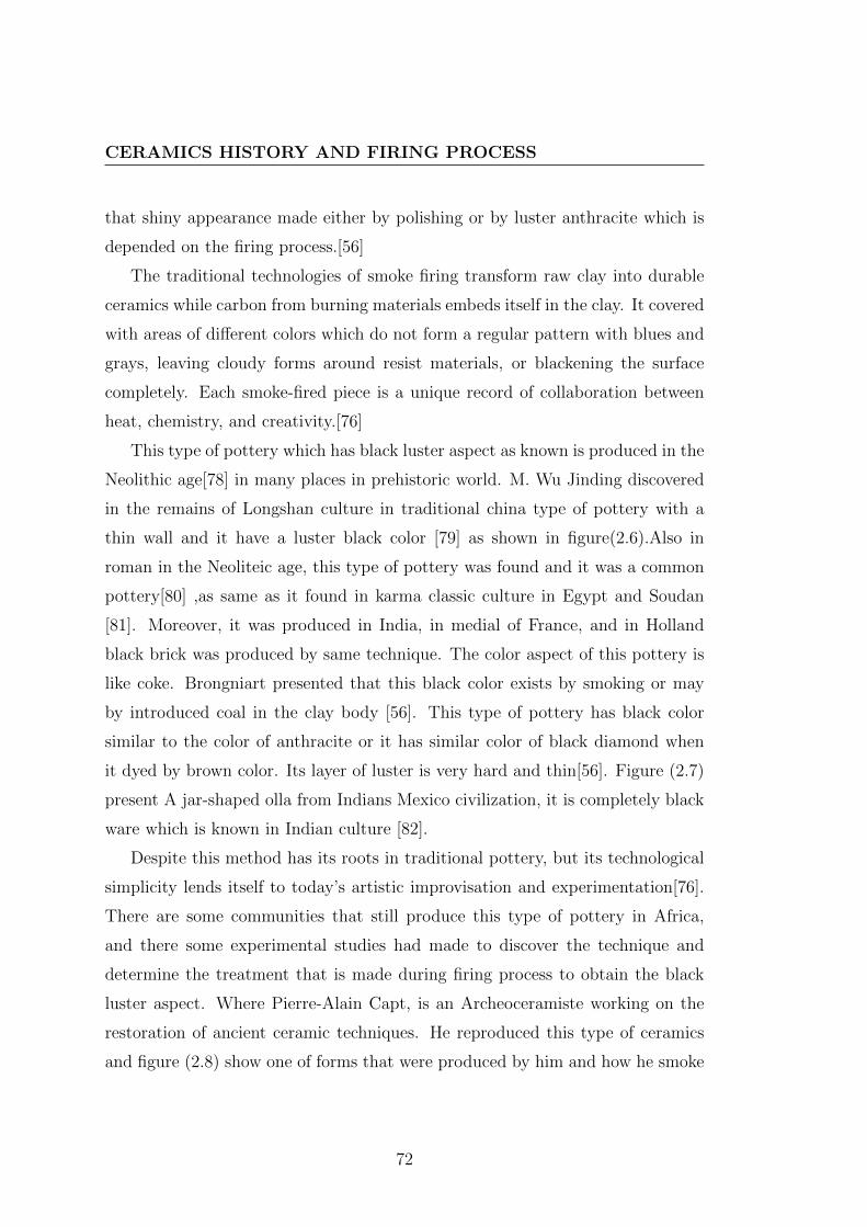
CERAMICS HISTORY AND FIRING PROCESS
that shiny appearance made either by polishing or by luster anthracite which is
depended on the firing process.[56]
The traditional technologies of smoke firing transform raw clay into durable
ceramics while carbon from burning materials embeds itself in the clay. It covered
with areas of different colors which do not form a regular pattern with blues and
grays, leaving cloudy forms around resist materials, or blackening the surface
completely. Each smoke-fired piece is a unique record of collaboration between
heat, chemistry, and creativity.[76]
This type of pottery which has black luster aspect as known is produced in the
Neolithic age[78] in many places in prehistoric world. M. Wu Jinding discovered
in the remains of Longshan culture in traditional china type of pottery with a
thin wall and it have a luster black color [79] as shown in figure(2.6).Also in
roman in the Neoliteic age, this type of pottery was found and it was a common
pottery[80] ,as same as it found in karma classic culture in Egypt and Soudan
[81]. Moreover, it was produced in India, in medial of France, and in Holland
black brick was produced by same technique. The color aspect of this pottery is
like coke. Brongniart presented that this black color exists by smoking or may
by introduced coal in the clay body [56]. This type of pottery has black color
similar to the color of anthracite or it has similar color of black diamond when
it dyed by brown color. Its layer of luster is very hard and thin[56]. Figure (2.7)
present A jar-shaped olla from Indians Mexico civilization, it is completely black
ware which is known in Indian culture [82].
Despite this method has its roots in traditional pottery, but its technological
simplicity lends itself to today’s artistic improvisation and experimentation[76].
There are some communities that still produce this type of pottery in Africa,
and there some experimental studies had made to discover the technique and
determine the treatment that is made during firing process to obtain the black
luster aspect. Where Pierre-Alain Capt, is an Archeoceramiste working on the
restoration of ancient ceramic techniques. He reproduced this type of ceramics
and figure (2.8) show one of forms that were produced by him and how he smoke
72

HISTORY OF CERAMICS THAT HAD TREATED DURING ORAFTER FIRING PROCESS.
Figure 2.6: Eggshell thin cup from Longshan Culture discovered in Shandong,
China, Peking University
73

CERAMICS HISTORY AND FIRING PROCESS
Figure 2.7: A jar-shaped olla with completely black luster, from Indian civiliza-
tion.
it after firing. The piece was buried in sawdust when it is hot. In the extraction,
it is still smoking. The figure(2.9) show the aspect of luster black treatment when
the piece became cold.
2.3.2 Ceramics with glazes .
The earliest only glaze was known for ancients that mainly made up of silica
(SiO2) which can be able to fuse by introducing an alkaline such as potash ∗
or caustic soda§ , and it is always colored by mineral oxide which is added to
compositions or which is diffused from surface of clay-body. In ancient Egyptian
pottery this type of glaze was thick , but it was thin in Roman pottery [56].
∗Potash is the ordinary name for different manufactured salts that contain potassium in
water-soluble forme[83].§Sodium hydroxide(NaOH).
74

HISTORY OF CERAMICS THAT HAD TREATED DURING ORAFTER FIRING PROCESS.
Figure 2.8: Smoking form of ceramic in sawdust to obtain luster black ware.
Produced by Pierre-Alain Capt.
Figure 2.9: luster black aspect appeared, when the form became cold.
75

CERAMICS HISTORY AND FIRING PROCESS
The plumbiferous glaze was common in Greek culture from Antiquity to the
Renaissance. The plumb-stanniferous opaque glaze which is considered as the
enamel is used to cover the enameled pottery which is called common faience,
majolica, and faience with stanniferous enamel. This type of glazes was used
for pottery fine and pottery matte, the glaze of stoneware is plumbiferous, while
other glazes which used for translucent ceramics, porcelain, are feldspar or alkaline
glaze[84]
With this information about the glazes modification over the history, the firing
process and treatment during or post-firing are important in changing the finale
appearance of the ceramics wares with glazes. Over the history, not only there
were some styles of ceramics which glazes is influenced by treatment during firing
process, but also there was some glazes created on the surface of ceramics by one
or more treatments during firing ,as well as, there some aspects was created by
the same way. Despite of the effects of doing treatment during firing or post-firing
are varied, but there are two main different treatments depending on the time
of treatment on schedule of firing. The first one is existed after heating period
complete outside the kiln or firing place as raku ceramics technique. The second
one treatment happens during the heating or cooling period inside the kiln or
firing place.
2.3.2.1 Stone were with led glaze (Raku ware )
Raku ware can be considered a modification of fringe method for anthracite black
pottery. The modifications are in chemical composts of glazes which applied on
surface of Raku ware, where in raku the treatment happened for glazes composts
while in anthracite black pottery the treatment happened for iron oxide in clay.
This style of Japanese pottery originated in Kyoto area of Japan during the
Momoyama period (1573-1615) that is usually used in the Japanese tea ceremony,
most often in the form of tea bowls. Its glaze is low fire lead glazed technique
that is transported from Fujian, China. Raku pots were placed in a small indoor
76

HISTORY OF CERAMICS THAT HAD TREATED DURING ORAFTER FIRING PROCESS.
Figure 2.10: traditional red raku tea bowl, red earthenware; clear glaze courtesy
of art complex, Museum Duxbury.MA.[8]
kiln, quickly brought up to firing temperature then they were removed from the
kiln to cool in open air. In Japan, there were two traditional types of raku back
raku which fired more slowly than the other type red raku. Figure (2.10) shows a
red raku tea bowl,(8.4×9.4 cm), created by Chojiro (1516-1592) and figure (2.11)
show black raku tea bowl,(9.5×10.2 cm), created by Donyu (1599-1656).[8] The
Ogama kiln is used for firing the traditional Japanese Raku-yaki or raku ware,
this kiln was built at the end of the sixteenth centaury.[10]
This style of Japanese pottery originated in Kyoto area of Japan during the
Momoyama period (1573-1615) that is usually used in the Japanese tea ceremony,
most often in the form of tea bowls. Its glaze is low fire lead glazed technique
that is transported from Fujian, China. Raku pots were placed in a small indoor
kiln, quickly brought up to firing temperature then they were removed from
the kiln to cool in open air. This technique transfer from Japan into western
world in 1911 and it became popular popularized in America in the late 1950s.
Raku technique in Australia refers to a firing method, which is existed quickly
heating and quickly cooling and red hot piece is immediately subjected to some
procedures which usually is thrust the piece in organic materials. Therefore, the
molten glaze treated by reduction and thermal chock and sometimes the effect
77

CERAMICS HISTORY AND FIRING PROCESS
Figure 2.11: traditional black raku, tea bowl, courtesy of art complex, Museum
Duxbury.MA.[8]
of thermal chock increased by water rather than air[85].The aesthetics of western
raku ware is varied where the colorants mineral oxides and the glaze structure were
diverse, as well as, the combustible materials effected on the aesthetic treatment
of surface.
The differences between Japanese and western raku.
The differences are integrally contained in method and philosophy, where Japanese
raku is a pottery created by descendants of Raku family for the traditional
Japanese tea ceremony. The Japanese raku was attempted just for traditional
ceremonies and rituals. Therefore, the traditional Japanese raku ware was not
subjected to combustible materials as reduction treatments post- firing.[60]
In western culture, the raku ware was known by Bernard Leach, where he
was admired by the fast firing to bowls without break during the rapid cooling
.therefore, the raku in western culture it is not tea ceremony. Warren Gilbertson
is the first American potter who studies raku seriously.[8] Also the western raku
wares are put in contact with some sort of combustible material after removing
it from the kin when they are hot , that is means its atmosphere converted
78

HISTORY OF CERAMICS THAT HAD TREATED DURING ORAFTER FIRING PROCESS.
Figure 2.12: western raku ware with treatment metallic glaze from SnCl2 fuming,
created by James C. Watkins
to carbonized and this treatment was created in unites states of America ,in
1960 by Paul Soldner and others. Therefore the western raku is free from the
traditional and culture, it is a form of art and its surface beauty combined between
spontaneous and induced effects of colors and textures. Figure (2.12) shows the
bird basket its dimensions (10.1×25.4 cm) ,its glaze was Duncan Antique brass
glaze, masking-tape stencils was used to decorate the form ; it fired to A 04 and
cooled to 800 F (427 C); stannous chloride fuming as the treatment post firing
from western raku, created by James C. Watkins [60]Figure (2.13) shows bowl
with crackle glaze as a treatment from western raku where most glazes craze
from cooling stress when raku fired ,and the carbon inters the craze lines creating
crackle patterns , its dimensions (20×5.6 cm) created by Michael Sheba [62]
79

CERAMICS HISTORY AND FIRING PROCESS
Figure 2.13: western raku bowl with crackle patterns exist as post firing treat-
ment, created by Michael Sheba.
2.3.2.2 Stone were with feldspathic glaze (Shino ware)
This type of ceramics also is traditional Japanese stoneware and its productions
required reduction atmosphere. Its glaze contains from 60 to 80 percent feldspar
and from 20 to 40 percent clay. It tend to range in color from milky white to a
light orange, and it have a spotting, haloing or lining of red or gray. The first
Shino was developed in Japan during the Momoyama period (1573-1615)[9]. Also
Ogama kiln was used to produce this type of ceramic [10]. There are styles of
the traditional Shinos when Shino glaze cover drawings painted in iron oxide,
they appear and disappear under the varying thickness of the glaze, creating a
magnetic effect. This style is known as e-Shino glaze where (e) means picture, as
seen in figure (2.14), a bowl tea from Azuchi-Momoyama - Edo Period 16th-17th
century, its dimensions are: high 8.2 cm, mouth diameter 13.1cm, and bottom
diameter 6.6 cm. When the drawings are etched into a layer of iron oxide which
is then covered in Shino glaze, the result is a grey field with light drawings. This
is known as nezumi Shino. Figure (2.15) show a bowl decorated by nezumi-shino
80

HISTORY OF CERAMICS THAT HAD TREATED DURING ORAFTER FIRING PROCESS.
Figure 2.14: Tea bowl, shino type, Mino Ware with Shino glazes cover drawings
painted in iron oxide, Tokyo national Museum.
style from Mino ware 16th-17th centuries, its dimension are: high 11 cm, mouth
diameter 28.5 cm.
Like raku ware ,the Shino ware technique has been transferred from Japan to
America and it have especial feature[61], where it is often known as carbon trap
which is trapping of carbon in the glaze during firing process[86]. This class of
Shino glaze called carbon trap Shino, Virginia Wirt improved carbon trap Shino
in the early 1970 and it is called the American Shino. Chris Gustin developed her
works to improve the aesthetes of American Shino. These glazes are modified from
the traditional Japan glaze where addition of 3 to 17 percent soda ash is added to
structure of traditional glaze. During the firing process the soda ash emigrate to
the surface of glaze, and this situation creates the possibility for carbon trapping
because soda ash is soluble. Therefore in heavy reduction atmosphere, carbon
will be deposited on the surface of ceramics forms. Melting soda ash will trap
81

CERAMICS HISTORY AND FIRING PROCESS
Figure 2.15: Bowl, nezumi-shino type, Mino Ware, Azuchi-Momoyama Period
16th-17th century, Tokyo national Museum.
82

HISTORY OF CERAMICS THAT HAD TREATED DURING ORAFTER FIRING PROCESS.
Figure 2.16: carbon trap Shino tea bowl created by Malcolm Davis.
the carbon and create a solid, spotted black or gray glaze [22]. Figure (2.16)
show carbon trap Shino tea bowl created by Malcolm Davis in 2003, it dimension
(8.3×7.6cm)[87]
The firing techniques of Raku and Shino wares and Jomon pottery in Japan
suggest confirming the hypothesis that considered the firing process technology
is an important factor which determines the aesthetic treatments, the structure
of glaze has the same importance. Where there were differences in aesthetic ap-
pearance between American Shino and western Raku due to differences in the
compositions of glazes. Raku glaze is a led glaze but Shino glaze is feldspathic
glaze therefore the effect of reduction atmosphere and smoking firing process was
different in its aesthetic treatments. Where in case of led glaze carbon react with
mineral oxide, while in feldspathic glaze carbon tapped inerter the glaze layer.
83
CERAMICS HISTORY AND FIRING PROCESS
2.3.2.3 Earthenware with luster glaze (metallic reflection)
The first application for glazes with metallic reflections was produced in Iraq
during Abbasid Caliphate period (750-1258), in IX century. This technique of
decoration was experimented on glass before it was used to decorate the ceramics
forms[12]. This type of ceramics was an important development in the history of
ceramics, and it is technique was improved to be the important decorative style
in the Islamic world and it has been transferred also to Europe[88]. Consequently
the luster techniques diffused right through the Mediterranean basin, where it was
known in Egypt in the end of IX century during the Tulunid dynasty (868-905)
and it was continued during the Fatimid period (909-1171). Also it was produced
in Kairouan (Tunisia) in IX century[11, 12, 13]. Whatever the Iraq luster glazes
were related to the Abbasid dynasty and it have especial forms and motifs. M.
Mason mentioned that Basra luster wares have motif and forms that is no other
wares like them, excluding the Egyptians Fustat luster wares which may be dated
to last quarter of IX century[88].
There were two types of decorations used in IX century: the polychrome lus-
ter that was rare and monochrome or one metallic reflection color and the figure
(2.17) show the different between the two types. Where tile (a is decorated poly-
chrome luster which is example of 161 tiles used in the Mihrab∗of the Sidi Oqba
mosque in Kairouan (Tunis IX century), and tile (b is decorated by monochrome
luster[89]. It was revealed recently that these types are produced in Mesopotamia
and bringing in Kairouan in IX century[90]. there are three groups of metallic lus-
ter decorations: polychrome with two tones; polychrome with three tones which
there motifs are geometrics and floral and they dated to the second half of the
IX century; and the third group is monochrome which its motifs are animal and
human ,it dated to first of X century[89].
∗Mihrab is the small space in one wall of the mosque, formed by one part of a wall being
further back than the parts on each side and it indicate the direction of Mecca.
84

HISTORY OF CERAMICS THAT HAD TREATED DURING ORAFTER FIRING PROCESS.
Figure 2.17: luster polychrome and luster monochrome glazes used in Mahrab of
Sidi Oqba mosque in Kairouan IX century.
There were some colors which are used in type monochrome, only the metallic
reflection, gold, red, or silver. This reflection metallic colors technique was used
to covered earthenware body in different qualities that may be quality of faience,
quality clay normal and sometimes quality of very low temperature terracotta[12].
R. B. Mason presented the chemical analysis for some clay bodies which are
covered by luster metallic treatments , from Iraq in , see table (A.1)[88], and O.
Bobin present the chemical analysis for some clay bodies which are covered by
luster metallic ,from Kairouan , see table (A.2)[90]. These analyses indicate that
the clay bodies materials have percents of iron oxides in range from 6.58 % to
9.00% for samples from Kairouan, and range from 5.9% to 6.4% for samples from
Iraq. Also these analyses refer to high percents of calcium oxide in range from
20.31% to 22.53% for samples from Kairouan, and range from 19.8% to22.5% for
samples from Iraq. The percents of magnesium oxide are in range from 6.05% to
7.88% for samples from Kairouan and in range from 5.9% to 6.4% for samples
from Iraq .That indicate to the quality of clay bodies which was a quality of
earthenware and it should be firing in temperature not more than 1000 C .
The glazes which were used in Mesopotamia in the IX century were diverse and
R. B. Mason dived them to three main glazes: alkali turquoise glazes (Turquoise-
85

CERAMICS HISTORY AND FIRING PROCESS
Figure 2.18: dish of flag-bearer (plat au porte-etendard),Iraq ,X century. earth-
enware, decorated by monochrome metallic luster on opacify glaze,louvre mu-
seum,department of Islamic arts ,MAO 23
86

HISTORY OF CERAMICS THAT HAD TREATED DURING ORAFTER FIRING PROCESS.
glazed class), lead-alkali opacified glazes (Opaque-glazed class), and simple lead
glazes (Lead-glazed class). Where Islamic potters known about the alkali glazes of
Mesopotamia and the high-lead glazes of the Romano-Byzantine Mediterranean,
they developed the two traditional glazes to these three basics glazes[88].
The chemical analyses which were presented by O. Bobin and Mason inform
that types of metallic reflections glaze in Iraq and in Kairouan are lead-alkali
opacified glazes, and table (A.3)[90]shows the oxides percents which compost
metallic reflection glazes from Kairouan and table(A.4)[88] shows the oxides per-
cents which compost metallic reflection glazes from Iraq .The tin oxide was used
to give the opacity.
The glaze that is used for this style in Kairouan include from 1.69 % to 4.31
% of tin oxide, from 6.87 % to 9.27 % of lead oxide, from 5.73 % to 7.79 %
of sodium, from 4.43% to 5.63 % of calcium oxide, from 2.95 % to 3.84 % of
magnesium oxide and from 2.88 % to 3.85 % of potassium oxide. The glaze that
is used for this style in Iraq include from 6.5% to 13.1 % of tin oxide, from 5.8
% to 14.4 % of lead oxide, from 5.8 % to 8.7 % of sodium, from 3.6% to 7.3 %of
calcium oxide, from 2.2 % to 3.5 % of magnesium oxide and from 3.4 % to 4.7 %
of potassium oxide.
These styles of aesthetic treatments for ceramics were modified in IX-X cen-
tury when this technique was transferred to Sues in Iran.The figure(2.19) shows
some fragments which are decorated by metallic reflection polychrome from Sues
in IX century and the color view is different depending on the angle of observation
and light impact [88]. this decoration was applied on background of white glaze,
and it was applied on high silica clay and stanniferous glaze.
In Anatolia .from 1077 to 1307, this technique was used to produce some
luster tile and it was decorated by human and animals motifs. In Iran under
domination of Seljukds (1038-1194) and in Anatolia under domination of Ayyu-
bids (1077 1307), the paste was used to produce the forms was highly silica and
white paste .the glaze which used to cover this paste was sometimes transparent
and sometimes lightly opacity[12].
87

CERAMICS HISTORY AND FIRING PROCESS
Figure 2.19: fragments of glazed ceramics which was decorated by metallic luster,
polychrome type, IX century, Sues, Iran.
The metallic reflection continued produce in Iran en period of Timurid dynasty
XV century in tile form and in (1588-1629).Its glazes was high quality and it was
applied on hard-high silica and forms have thin wall and figure(2.20) show one of
this ware that are in museum of ceramics Sevres[89].
Also there were some fragments from Fustat Egypt which indicate that this
style was produced in Egypt on highly silica and white paste that was good mixed
past. The glazes which were used to cover this paste were transparent sometimes
iridescent[91].
The metallic luster decoration and glaze flourished in the second half of XIV
century in western region of the Mediterranean[12].The metallic luster technique
was produced in Spain and the first examples for this technique in this region
were found in Murcia and dated to twelfth century[92]. Then it was produced in
large mass at Manises near Valencia where there are many similarities between
the luster of Christian Spain and the earlier luster of the south.The ceramics
which were produced in this period are called Hispano-Moresque. The Moorish
88

HISTORY OF CERAMICS THAT HAD TREATED DURING ORAFTER FIRING PROCESS.
Figure 2.20: high quality metallic reflection decoration on opaque glaze and the
body was hard and high silica.
89

CERAMICS HISTORY AND FIRING PROCESS
Figure 2.21: A Hispano-Moresque dish , approx 32cm diameter, with Christian
monogram ”IHS”, decorated in cobalt blue and gold luster. Valencia 1430-1500.
Burrell Collection.
craftsmen who had moved from Andalucıa actually made the luster ware in Man-
ises during Christian kingdoms[93]. The Moorish potters in Spain developed the
ornamentation style to adapt with the requirements of their new societies, the
figure (2.21) show the adapted ornamentation with continued use of arabesque
traceries, stanniferous enamel and metallic luster. Some of Hispano-Moresque
plaques are superimposed luster and identical. It is of brownish yellow tone, but
when the angel of view is changed, the brownish yellow tone is seen a bluish
violet[94].
In the early sixteenth century, the Hispano-Moresque luster had some different
90
HISTORY OF CERAMICS THAT HAD TREATED DURING ORAFTER FIRING PROCESS.
and beautiful luster. It was produced in Muel and Catatayud beyond Zaragoza
also in beginning of sixteenth century. In the end of fifteenth century the Moulded
cuenca tiles with lustred surfaces were produced by different techniques. Where
the tiles appear to have been flooded with luster pigment, and this Seville tech-
nique is related to method which is known as cuerda seca . Its clay was covered
by glazes of different colors, without any brushwork[93].
During the thirteenth to fifteenth centuries the metallic luster decorated Hispano-
Moresque which was tin-glazed was widely exported through the Mediterranean
Sea. The transparent led glaze was also produced in considerable large amount.
The copper-like color of metallic luster was produced in fourteenth century instead
of the gold-like color which was known in thirteenth century[95] The figure(2.22)
shows two-handled pot was decorated by copper-like color on tin-glaze.
The metallic luster technique was introduced into Italy by Moors. During
the XIV and XV centuries, it was produced in the center of Italy, where the
well known polychrome luster Renaissance ceramics was exploited to produce in
Deruta and Gbbio,and it take new name which is majolica, [11, 12, 93, 94].
Metallic luster glaze has this deep root in history, and it was developed from
era to era depending on the general factors that were mentioned in second chapter
in section(1.4) .but the main common denominator in its technology over the
history is that it was produced by treatment during firing process. This treatment
is reduction, where the carbon reacts with mineral oxide to create Nano-particales
of mineral[96]. The commons mineral oxides that were used as colored in glaze
to obtain the metallic luster were silver and cooper colored materials and oxides.
The aspect metallic of copper and silver are obtained by redaction atmosphere, in
temperature at or below 650 -700 C.[97] the redaction atmosphere is a treatment
during firing where the results are very sensitive temperature and amount of
redaction gases.
Where the reduction treatment during the firing process is a chemical process;
it was created by limiting the combustion air in the interior of fuel kilns which were
the developed in this time. Therefore the carbon monoxide (CO) will appear in
91

CERAMICS HISTORY AND FIRING PROCESS
Figure 2.22: two-handled pot on a pedestal foot 22cm high probably from Va-
lencia ,second half of 17th century, Instituto de valencia de Don Juan. Madrid
.
92

HISTORY OF CERAMICS THAT HAD TREATED DURING ORAFTER FIRING PROCESS.
the combustion gases. It is unstable compound which still needs some oxygen that
was taken from metallic oxide susceptible to this treatment. Monoxide converts
itself to dioxide, the more stable state. Metallic oxides loss oxygen and its status
also were changed as well as its color[98].
2.3.2.4 Porcelain in redaction atmosphere and crackle
In china during the Sung dynasty (690- 1279), there were five important clas-
sics wares that were produced in this dynasty, and the treatments during firing
were the responsible about their especial aesthetics. The aesthetic treatments
of ” five great wares ” in song dynasty were depended on the colors like white-
color, sky-blue, green and blue-green, in addition to other treatment which is
texture of crackling surface. The technique of crackle appeared in twelfth cen-
tury. There were some styles which are interplays in crackled treatment, but they
are different in colors and forms. These styles are: Ru kiln, Ge Kiln, Guan kiln,
and Jun kiln. In Sung dynasty ,The art of porcelain entered era of unmatched
success[99],and the imperial kilns classified to northern Sung kilns and south-
ern Sung kilns[100].The song dynasty was the most important period in imperial
Chinese history[15].
-Ru Kiln
The Ru kiln is one of imperial kilns from northern Sung dynasty[14].The Ru
Guan kiln site is located in Qingliangsi, Baofeng County, Henan Province in
China. It was produced for the royalty in the late Northern Sung dynasty (1086-
1125)[101]. this glaze was thin , and the color of glaze ranges from white-blue,
sky-blue, blue-gray, sky green, light green , pea green to pale blue [99, 101]. The
white-blue porcelain from Ru kiln was famous[100]. This style of porcelain was
only used in the imperial palace, due to there is agate in its glaze. only just
some pieces which are rejected from the supplies to imperial palace can be sold
and used outside the palace .The body of this kind of porcelain was light gray in
color as the incense ash or gray-brown color, and it was thin body [14, 15, 98].
93

CERAMICS HISTORY AND FIRING PROCESS
This firing process existed while the body was put on the nail-support in reason
to glaze the body completely. Thus there were very tiny ”sesame-seed” which
marks were left on glaze surface[15, 101].These supports have from three to five
studs[14]
Ru kiln wares were produced for just about 20 years only. Nowadays, this style
is very rare, where there were only 70 intact pieces of Ru wares which have been
collected all over the world[15]. Ru ware has glazed surfaces which are usually
crazed. Its glaze is a celadon-glazed with a relatively thick iron-blue glaze of
especial beauty [98].
This style was imitated at Jingdezhen in the Xuande period (1426-1435). But
the bodies of copies are less hardness than original of Ru kiln from Sung Dynasty,
the glaze slightly more transparent and the crackles more dense. Also during the
Qing period (1644-1911) there was the best imitation of Ru kiln wares, and it
was created during the Yongzheng era but the glaze of the imitation which called
imitation bronze vessels of Ru glaze was too transparent. A few imitations were
decorated with embossed or impressed designs, and the shape was also different
from that of Ru ware of Sung Dynasty[14]. Figure (2.23) shows a cup-stand of
Ru wares, its diameter is 16,2 cm, its height is 7.6 cm, and its form is similar to
forms that occur in Chinese lacquer and silver in Sung Dynasty[102].
-Jun Kiln
Jun porcelain is located in Juntai, Yuzhou city, Henan province. Its glaze
layer was thick, where it was glazed twice, the glaze colors range from sky green,
sky blue, pale blue, rose purple, crabapple red to grape purple[101].
The pale blue was a celebrated glaze color which was used to cover this ware
style. It was invented during the northern Sung Dynasty. In addition to its
glaze is thick, also it is opalescence (its color reflects light and changes when the
position of the person looking at it changes) and translucent. It was considered
that these glazes are celadon even though their color often termed robin’s egg blue.
This distinctive color was created as result of that the glaze separate naturally
into silica-rich and lime-rich glasses during firing process. The iron oxide is the
94

HISTORY OF CERAMICS THAT HAD TREATED DURING ORAFTER FIRING PROCESS.
Figure 2.23: Ru ware cup-stand From Qingliangsi, Baofeng county, Henan
province, northern China Song dynasty, late 11th- early 12th century, British Mu-
seum OA 1971.9-21.1
Figure 2.24: Three-legged wine vessel Ru ware of Northern Song Dynasty, 11th
Century
95

CERAMICS HISTORY AND FIRING PROCESS
coloring agent in the glaze of Jun ware, and the color of glaze determined on
the stats of iron oxide which are arose after firing in reduction atmosphere.Its
opalescence also happened from the phase separation where during at last stage
of firing, while its degree was about 1200 C or little below, the transformation of
melted glaze into an emulation of tow phase or liquid as silica-rich and lime-rich
glasses causes the phase separation especially when the kiln was cooled slowly
[103].
The glaze color of Jun porcelain also gives the feeling of color clouds, and it
is very sensitive to the firing conditions. Where different colors can produce from
firing with the same material in the same kiln[104].This style of porcelain has
been high reputation[101].
In the early of twelfth century and continued to thirteenth century, Jun ware
pieces was decorated by splash of lavender ,purple or royal blue. As thinking, the
potter used the filings of copper oxide to glaze before firing to produce this color,
where at first they used the sprinkle filings, and then they mixed the filings with
water may be with some of glaze to apply the solution by brush.[103].
-Guan Kiln
Guan kiln as Jun kiln and Ru kiln are from the five great kilns of Sung Dynasty,
it takes its name from the meaning of Guan, and it means official or government,
where this style was produced for using in the imperial court that was after sting
up the Ru kiln. Emperor Huizong who had ordered the construction of this
style in Northern sung Dynasty. There was also Guan kiln of the south which
was produced in new capital Linan. Where the sung court fled to south of the
Changjian (Yangtest) river[14, 105].
the clay body of Guan kiln is dark due to it is iron-rich clays ,and its glaze
is thick that created multiple crackle systems in cooling. This thick glaze was
achieved by multiple glaze application on wafer-thin bodies. The benefit of the
dark iron-rich clay is enhancement the apparent depth of crackled glazes[102].
The thick glaze layer trickled at the brim to leave the rim glaze layer thinner
there than on other parts of the body. The iron oxide which fond in the clay
96

HISTORY OF CERAMICS THAT HAD TREATED DURING ORAFTER FIRING PROCESS.
Figure 2.25: Jun wine jar Moon-white glazed with vertical flanges northern Sung
dynasty
Figure 2.26: Imperial Jun ware;Northern Song
97

CERAMICS HISTORY AND FIRING PROCESS
Figure 2.27: Northern Guan ware
in form ferric oxide (Fe3O4) comes from firing in reduction atmosphere. If the
bottom rim is black, it called iron-foot , this artistic style known as famous
purple rims and iron-feet [105].Figure (2.27) show the guan ware that was made
in Northern sung[106].
-Ge kiln
Ge kiln glazes colors were light greenish-blue, Moon-white, glossy-gray and
yellow green. This crackle is different than others styles, where there was a net
of crackle coats the surface of glaze which is similar to ice-crackles, fine crackles,
or fish egg crackles. The areas enclosed within cracks can vary from the widely
spaced to narrow as small as fish egg[99].
The large crackles are dark brown, and the smaller crackles are yellow brown.
This style of crackles was known as ”golden wire and iron thread”. Figure (2.28)
shows a five stud jar from Ge kiln and the distinguish crackles appear on glaze
98

HISTORY OF CERAMICS THAT HAD TREATED DURING ORAFTER FIRING PROCESS.
Figure 2.28: Ge five-stud water jar, sung dynasty
surface. The bodies of Ge wares are purplish black, iron black or yellowish brown
in color. The glazes are non-transparent[14].Figure(2.29 show Ge-type vase which
has thick, opaque grey glaze with two layers of crackle, the wide crackle stained
grey and the fine crackle brown. It was made in Zhejiang province (1279-1368),
Yuan dynasty.
Ge Kiln porcelain belongs to the celadon family. The both of Ge like wares
and Guan like wares could have considered from the same kilns, and dragon kiln
provided the natural variation of atmosphere, temperature and cooling that was
required for their aesthetics treatments[102].This style was imitated in Jingdezhen
in the Yongle (1403-1424) and Xuand periods of the Ming Dynasty[14]. Figure
(2.30)show one form from this imitation Ge style.
From this Chinese ceramics styles, the role of firing process in the aesthetics
treatments is demonstrated. Where atmosphere of kiln, temperature and cooling
kiln is important in produce these styles and produce theirs glazes’ color. The
99

CERAMICS HISTORY AND FIRING PROCESS
Figure 2.29: Ge-type vase which has thick,Zhejiang province (1279-1368), Yuan
dynasty.G95/case2/sh4 British Museum
100

HISTORY OF CERAMICS THAT HAD TREATED DURING ORAFTER FIRING PROCESS.
Figure 2.30: Ge five-stud water jar, sung dynasty
101

CERAMICS HISTORY AND FIRING PROCESS
reduction treatment during the firing process is a chemical process; it was created
by limiting the supply of combustion air. Therefore the carbon monoxide(CO)will
appear in the combustion gases. It is unstable compound which still needs some
oxygen that was taken from (Fe2O3) (red iron oxide) which is a susceptible to
this treatment. Monoxide converts itself to dioxide, the more stable state. The
(Fe2O3) loss oxygen and its status also were changed as well as its color. Thus
the may became(Fe3O4)(magnetic iron oxide) and then (FeO) (black iron oxide)
as redaction process strongly augments[98].
The treatments of crackle could have existed by many causes which create
a compression stress or a tensile stress in glaze layer. These causes refer to
physiques treatments as well as reduction atmosphere refer to chemical treatments
what happened during firing. The both treatments were existed to produced
these Chinese porcelain as one of them was used to produce others styles that
mentioned in this chapter. Most types in classification of wares have one or more
of style which firing condition or treatments during firing were the responsible
about their feature. this conclude to importance of firing process and led to
consider kiln design as a tool for creating some aesthetic treatment on ceramics
surface.
102

HISTORY OF CERAMICS FIRING PROCESS
2.4 History of ceramics firing process
The important thing of firing process comes from that it is a deliberate process
which prepares the heat treatment for ceramics bodies and their glazes. The
technology of this heat treatment has deep root in history, and it was varied from
culture to another and from place to other. The essential aim of firing process is
sufficient solidity that was given to ceramics forms by heat treatment. Natural
properties of clay determine the degree of heat that required for giving forms
sufficient solidity. The technology of firing and its method were adapted over
history to permit the temperature which is required. In spite of solidity is the
essential aim of firing process, but this method and this technology shows more
over influences on aesthetics treatments. Therefore, these influences were taken
in consideration which imposed to develop firing and kiln technology.
Atmosphere of firing could be a main factor which influenced the final appear-
ance of pottery during firing. History of firing demonstrates the relation between
the firing technology and the atmosphere of firing. When firing process happened
in place of firing that can be an open place, then the firing called open firing or
can be a closed place, then firing is called firing in kiln. The structure of kiln
and the heat resources are conception factors that could be used to control the
atmosphere of firing.
2.4.1 History of firing process atmosphere.
Development of firing process over the history made change of the atmosphere in
pottery surroundings .when in primitive firing the objects are fired in atmosphere
surround by flam, gases of combustion, vapors and ashes of fuel materials due to
the heat resource was a result of chemical reaction during burning and the firing
process was in open air, the oxygen which is necessary for continuing the reaction
is sufficient or little less. Therefore the atmosphere of primitive firing is near to
reduction atmosphere and ceramics surfaces contact with gases, vapor and ashes
103

CERAMICS HISTORY AND FIRING PROCESS
which they affect in aesthetic treatment. Firing in open place means that there
was no heat isolation. Therefore, the heat which could be achieved by open firing
is low temperatures∗.
Firing in kiln was made separation between pottery objects and ashes; even
the kiln structure was simple. However, the gases of combustion and vapors
which were produced from fuel materials are still in contact with surface of ob-
jects. Design of kiln structure and architecture affect in air circulation and the
amount of air normally was less than that was required to complete combustion
reactions. Therefore, the almost fuel kiln is reduction atmosphere if there is non
air supply or muffle to protect the objects from gases and vapor of combustion.
With appearance of kiln in firing technology, the heat isolation and heat transfer
was applied to achieve midrange temperatures or even very high temperatures.
Construction of kiln was used to collapse the loss of heat and it used to store the
heat inside the kiln until achieving required temperatures.
After discovering the electricity, electric energy was used as resource of heat.
The structure of kiln changed to one chamber contacted with electric power sup-
ply or it changed to deep tunnel in case of continuous firing. Therefore some
mechanical parts was added to the structure of kiln . Atmosphere of kiln became
normal and it could be oxidized atmosphere by air supply unit. Also gas was used
as fuel materials. This discover made and changing in the traditional structure of
kiln. In gas fuel kilns the oxygen which supply from air circulation is important
and atmosphere of firing is determined by amount of air.
The ceramists adapted their firing technology in order to create aesthetic
treatment. They used the saggar to protect ceramics forms from surfing gasses
inside the kiln. There are some aesthetic treatments which were created as re-
∗Very high temperatures” usually mean >2300 F (>1260 C), ”high temperatures” = 1900-
2300 F (1038-1260 C), ”midrange temperatures” = 1100-1900 F (593-1038 C), and ”low tem-
peratures” = < 1100 F (<593 C).
104

HISTORY OF CERAMICS FIRING PROCESS
sults of especial firing technology. Also the modification of technology and heat
resources over the history affected the firing technology and its atmosphere.
2.4.2 Primitive firing
The first thermal treatment for clay in history was in open air and in pit. So it
was developed to bonfire and bonfire with mud-covered bonfire. Primitive firing
technologies were widespread in ancient cultures. Its methods and techniques are
diverse into many broad types as flowing:
2.4.2.1 Overground firing
In this method of firing, pots and objects were arranged into a pile on flat part of
ground, on an elevated platform, or in a shallow hole. The fuel was put in below,
among, and /or above the pots and objects. The pile of pots and objects could be
arranged in many shapes that give three distinguish open firing techniques and
methods. Open firing without any fire-channel and open firing carved by mud or
shells, this technique distinguish to open firing with apical fire-channel and open
firing with horizontal fire-channel[37].These distinctions of open firing be likely
to achieve low temperatures 800-900 C [107].
• Open firing without any fire-channel
It is simplest form of firing technology, where the pots placed in the flat
ground. Wood, dray cattle-dung and /or straw were fuel materials[37].Thus
rate of firing in this method was fast. Where the burning exists in air with-
out any covering therefore the time of firing is short. In 1998, an experi-
mental study to simulate the firing technique to explore the way of manu-
facturing black-topped Egyptian pottery. Maximum temperature could be
reached by this method at between 700 to 800 C [25].The potters could use
two ways to avoid the effect of thermal chock with heating in short time in
105

CERAMICS HISTORY AND FIRING PROCESS
Figure 2.31: open firing with preheating technique in the start of firing
process[25].
this method. The first one is increase resistant of clay to thermal chock by
adding the chamotte, grog, sand, and other materials. Second one is pro-
cedure during firing. Where fuel wood was spread out at some distances,
after preheating slowly the firewood was gradually moved closer to pots in
order to complete firing process. Figure (2.31) shows a simulation of this
technique of preheating.This type of firing is still used in Africa .
• Open firing with apical fire-channel
In this method of open firing, pots were arranged in circular form in number
layers ,so, in final state, the pile of pots became in form of dam. During
the arrangement of pots, a free space is left in center which make vertical
channel that opens in the top of dam.The fuel was put among and in-
between pots and its layers. The fuel is connected with channel which
created from a pile of pots. This makes a form of entire pile which is then
covered by grass or husk to be covered with mud. The top of channel is
left open through to cause a fire to start burning[37]. This type of firing
106

HISTORY OF CERAMICS FIRING PROCESS
is still used in East Asia, and it is called Yunnan style. In this method,
the fuel takes time to completely burn because of a small amount of air
supply. The air supply is not direct as in the open firing without any fire-
channel. Therefore also, the temperature that could be achieved is near
1000 C [25].In this method, due to indirect air supply the atmosphere of
firing is from reduction to heavy reduction. Refer figure(1.12).
• Open firing with horizontal fire-channel
The arrangement of pots in this method of firing takes deferent form; they
are arranged in radial rows at bottom layer to form circular base permit-
ting a contracted passage in between every two rows which works as a fire-
channel. This passage down the pile of pots runs straight across diametri-
cally opposite. The passage make stoke-holes on both sides of fire-channel,
the old pot used to prepare the stoke-holes which used to kindle the fire.
The fuel is placed in this method as well as in open firing with apical fire-
channel. The firing begins slowly then gradually gets much worse when it is
stocked with a poker [37].With this technique of firing, the potters avoided
the surfing effect of thermal chock on the pots and objects.
2.4.2.2 pit firing
In this style of firing, there is a deep pit which is dug in ground to make the firing
inside. This method is a clearly noticeable improvement over open-firing that are
made aboveground or on pit not deep. The firing in the pit makes advantage
to contain the fire in pit and the wall of pit help to hold the heat in. Usually
around the pit there is a rime which made of dirt. The bottom and sides of pit
are covered with fuel layer such as kindling. Tree branches and dray dung were
used as fuel in this method [108].
107

CERAMICS HISTORY AND FIRING PROCESS
Figure 2.32: Pit firing before firing[25].
The figure (2.32) show the a simulation to pit firing [25]. The pots placed on
layer of fuel in the pit, gaps between the pots are filled by fuel and then the pile
is covered by the fuel also.
2.4.2.3 Oven (pit with walls)
A permanent structure of oven appears in the method of firing and it is made
of clay, stone or bricks. Inside this structure of oven, pots arranged inside sur-
rounding walls. Elevated platform is fixed at equal distance near the stoke-hole
.pots are placed upon this platform which made of clay props. The interior of
posts is filled by fuel, and also it is put in gaps left in between pots. This exists
during the process of instillation the pile of pots, and then it is covered by pot-
shards. The firing start burning slowly at stokes holes. Bit by bit, it is gradually
increased. The heat in this method is more conserved than in open-firing[37].
Due to there was a structure that built with a pit in this method ; so the oven
firing is considered to be the beginning for creating kilns.
108

HISTORY OF CERAMICS FIRING PROCESS
2.4.3 Firing in kilns
With development of firing technology, the fixed place for firing was known with
pit firing, and a simple structure was known with oven firing. In kiln firing,
the separation between fuel and pots begins to appear. Therefore, transfer the
heat from fire box to firing chamber where pots are stocked to treat by greater
retention of heat. This process of separation between the pots and burning fuel
was existed in two methods: first, the pots were above the place of burning;
second, fuel burning is beside pots in cave digging in mountainside[61].
Kiln which is designed as first method called up-draft kiln where the axe of
transfer of heating across the pots is vertical, which the kiln which is designed
as second method called down-draft kiln where the axe of transfer of heat across
the pots is horizontal. Some of up-draft kilns are open from the top so it is called
open kilns. With this structure of kilns the temperatures which could be realized
were increased because heat become better isolated and conserved inside the kiln,
and the structure of kiln permitted to feed the firing and increase the duration
of firing.
The ancient kilns generally are composed from four principals parties. These
parties are the hearth or fire-box, the holes of air vents, the firing or kiln chamber
and the chimney. The fire-box is the place of combustion; holes of air vents are
very important part in structure of all fuel kilns. They feed reaction of combustion
by air which is very important to this reaction, and also their importance comes
from their position determined by the direction of air and heat transferring, firing
chamber is place or part of kiln where the objects and pots are put to treat by
heat as required and the chimney in case of open kiln the chimney is the door of
charging and discharging the kiln and it is in top to kiln as in ancient Egyptian
kiln and Greek kilns but in other type of kilns it take cylinder form in closed kilns
and its position in the kiln structure determine the direction of heat across the
firing chamber [5, 56].
109

CERAMICS HISTORY AND FIRING PROCESS
Ancient designer of kilns aimed to achieve higher temperatures especially to
produce stoneware and porcelain therefore they created the downdraft kiln which
it could achieve temperature of 1300 C. The direction of transfer of heat inside
the kiln was attractive to improvement structures of kilns from culture to an-
other; the choice between the firing technologies in specific culture is decided by
environmental, social, economical and requirements [5].
2.4.3.1 Up-draft kilns
This kind of kiln have very deep history where available information about an
engraved depict ancient kilns in Egyptian history, the engraved show simple kiln
in cylindrical form and refer to vertical heat transfer .see figure (2.33). From
engraved, the structure of kiln seems to be a building not a digging. So from this
information the updraft kiln was known in ancient Egypt. This engraved was
plotted on the walls of hypogeum of Bin-Hassan in Luxor. (XVIII century BC -
XIX century BC)[56]. The figure show the recharge the kiln where the pots are
placed inside the kiln from the tope D. In other figure the firing process is started
and the flame appear in the top D . This type of kiln called open-top kiln and it
is sample kiln.
In China, Yangshao culture was discovered in 1921 developed which was Ne-
olithic culture (VII century BC-IV century BC). Up-draft kiln with open top was
found in Banpo site that was used to produce black and gray potteries. The fig-
ure (2.34) demonstrate that it was dug in hill[27]. Two designs of up-draft kilns
appear in this figure: first one is composed from two chambers over each other;
the upper one is firing chamber and the other chamber is fire-box and there is a
hole between them, the flame passes through this hole from fire box to the firing
chamber; second one is a tunnel in hill and it take slope form from the box fire
to the top of hill where the chamber of firing.
There was a roman kiln which was an open updraft kiln. It was discovered
in nineteen century in Normanton Field-Castor in England. Its fire mouth is
110

HISTORY OF CERAMICS FIRING PROCESS
Figure 2.33: Engraved was plotted on the walls of hypogeum of Bin-Hassan in
Luxor[26].
in lateral position,there was a pit fire under the firing chamber which is open
from the top to lode the kiln. So the axe of heat circulation is vertical. Heat
transfer from fire mouth and firing pit to firing chamber through spy-holes which
distributed over the surface of floor between the fire pit and firing chamber[26, 56].
See figure (2.35)
This kiln was built in grand pit and brick and stones were used to complete the
structure and architect of kiln. This refer to begging of medication the structure
of kiln from natural pits or two pits to building structure which required artificial
materials to complete the design of kiln.
Most of known Greek kilns are of sample updraft type[5, 7]. The shapes of
small kilns in ancient Greece were circular or elliptical but there were excep-
tions of some rectangular kilns which considered as larger kilns. The temporary
domed superstructure was appeared in ancient Greek kilns, where they were
stone-constructed and it was suggested that temporary dome would have made
of clay mixed turf ,straw and even wasters from previous firing[7]. Updraft heat
111

CERAMICS HISTORY AND FIRING PROCESS
Figure 2.34: kiln for firing ceramics,Banpo site,Yangshao culture [27].
112
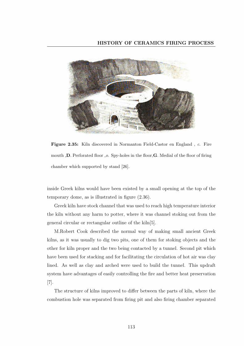
HISTORY OF CERAMICS FIRING PROCESS
Figure 2.35: Kiln discovered in Normanton Field-Castor en England , c. Fire
mouth ,D. Perforated floor ,o. Spy-holes in the floor,G. Medial of the floor of firing
chamber which supported by stand [26].
inside Greek kilns would have been existed by a small opening at the top of the
temporary dome, as is illustrated in figure (2.36).
Greek kiln have stock channel that was used to reach high temperature interior
the kiln without any harm to potter, where it was channel stoking out from the
general circular or rectangular outline of the kiln[5].
M.Robert Cook described the normal way of making small ancient Greek
kilns, as it was usually to dig two pits, one of them for stoking objects and the
other for kiln proper and the two being contacted by a tunnel. Second pit which
have been used for stacking and for facilitating the circulation of hot air was clay
lined. As well as clay and arched were used to build the tunnel. This updraft
system have advantages of easily controlling the fire and better heat preservation
[7].
The structure of kilns improved to differ between the parts of kiln, where the
combustion hole was separated from firing pit and also firing chamber separated
113
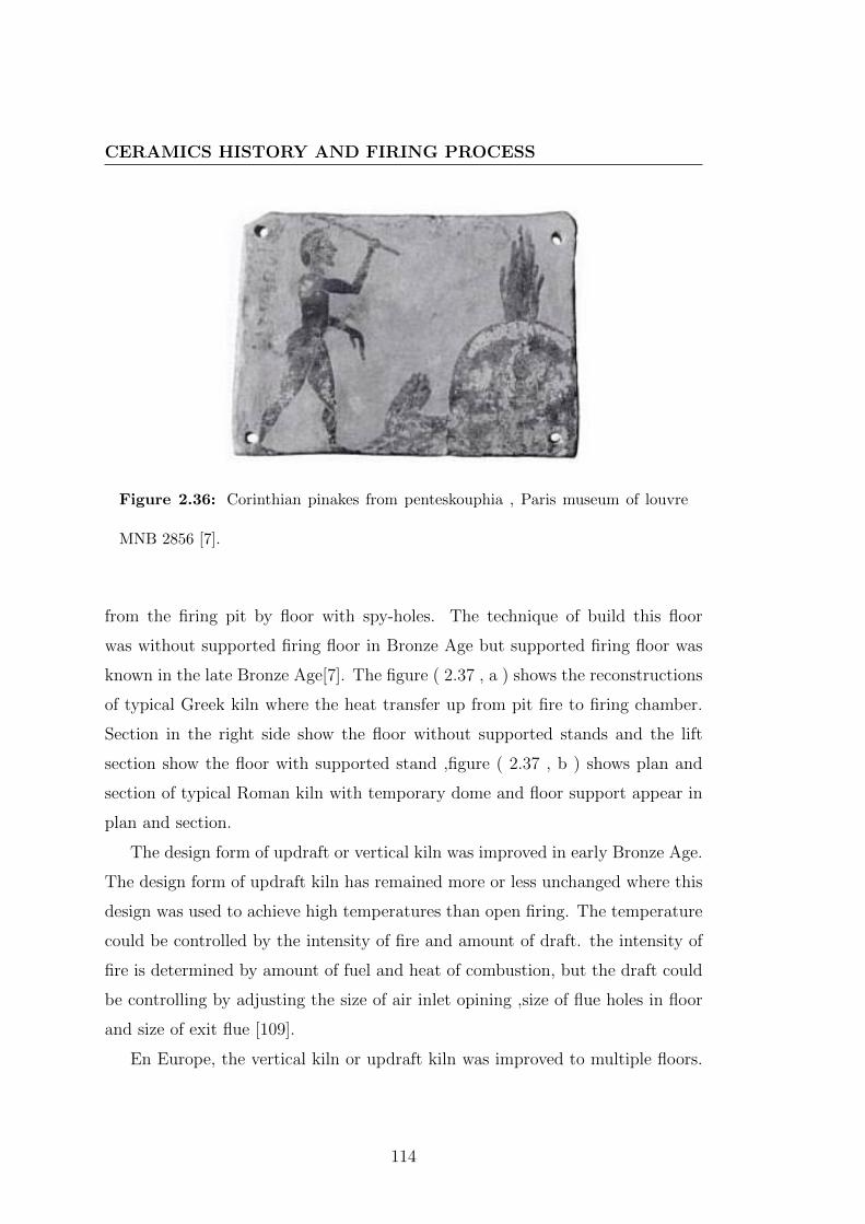
CERAMICS HISTORY AND FIRING PROCESS
Figure 2.36: Corinthian pinakes from penteskouphia , Paris museum of louvre
MNB 2856 [7].
from the firing pit by floor with spy-holes. The technique of build this floor
was without supported firing floor in Bronze Age but supported firing floor was
known in the late Bronze Age[7]. The figure ( 2.37 , a ) shows the reconstructions
of typical Greek kiln where the heat transfer up from pit fire to firing chamber.
Section in the right side show the floor without supported stands and the lift
section show the floor with supported stand ,figure ( 2.37 , b ) shows plan and
section of typical Roman kiln with temporary dome and floor support appear in
plan and section.
The design form of updraft or vertical kiln was improved in early Bronze Age.
The design form of updraft kiln has remained more or less unchanged where this
design was used to achieve high temperatures than open firing. The temperature
could be controlled by the intensity of fire and amount of draft. the intensity of
fire is determined by amount of fuel and heat of combustion, but the draft could
be controlling by adjusting the size of air inlet opining ,size of flue holes in floor
and size of exit flue [109].
En Europe, the vertical kiln or updraft kiln was improved to multiple floors.
114

HISTORY OF CERAMICS FIRING PROCESS
Figure 2.37: a) reconstructions of typical Greek kiln b)plan and section of typical
Roman kiln [7].
115

CERAMICS HISTORY AND FIRING PROCESS
Some kinds of kilns are sample were just multiplied firing chambers and the
other kinds are complex because they composed of many floor in check floor
there are firing chamber and fire mouth. Brongniart mentioned to these kilns.
The rectangle kiln was first put into practice as multiple level kilns, but the
temperatures were in general very unevenly distributed. Therefore, the different
products which are required different temperatures for firing were put in different
parts or firing chambers in these kilns. In this kilns the thick walls and envelopes
are required and the floor which is separate between each chamber of kiln is vault
arch. This structure of kiln cause to increase the quantity of heat loss during
firing process and the process take very long time and more amount of fuel to
complete the heating [56].
The idea of a high vertical kiln drawn attention to science and construction
of kilns. It was subtle and complex in the early nineteenth century. High vertical
building was preserved by designing iron bands and frames around the kiln and by
using materials which could withstand many firing[7]. Practical ideas in architect
were used to construct building of kiln.
The vertical cylinder kiln with laterals mouths firing help to solve most disad-
vantages in rectangle kiln. When the design of kiln was improved to have many
fireboxes. This kiln called in France Alandiers kiln and it used for firing hard-
paste porcelain. In England this kiln was used for producing the fine faience and
this kiln are used also to produce different type of ceramics in Europe. From
the name of this kiln it has cylinder form in base and firing chamber but its top
closed by segment of a sphere. This type of kiln has variation number of mouth
firing and combustion chamber, these variations are from three to eight and ten.
In general there are two forms of Alandiers kiln, one type is sample and other
one is complex. Brongniart mentioned that the complex form of alandier kiln was
produced after thirty years of produce the sample form [56].
116

HISTORY OF CERAMICS FIRING PROCESS
2.4.3.2 Down-draft kilns
The design form of this kind kiln was improved from digging a tunnel as mod-
ification to pit firing in Japan Korea and China. The primary design of this
kiln was called Anagama kiln where this name translate to ”hole kiln”. The first
design of down-draft kiln was a single-chamber without separation between the
wood burning in the fire-box and ceramics wares.This style of kiln was produced
to achieve the temperature that required for firing the stoneware[61].
The down draft kiln form is a domesticated idea to achieve high-fired technol-
ogy ,where its design depends on the arrangement of elements along horizontal
axe rather than vertical axe. Fire box is located in the front and the flue exit
from back side, between the fire box and exit flue ,the objects were placed from
the end of fire box to treat by heating in the chamber firing. When the hot gases
take direction toward the flue exit[109].
The sample or basic form of horizontal kiln called in Korea Tonggama where
in Korean Tong means a hole or a space this style of kiln introduced to Korea
from Han density China (206 BC - AD202). The elements of kiln structure are
dug in hill side with slope from 25 to 32 [6].There was an example of cross-draft
or down-draft kiln that was popular in Crete during the Neopalatial period [7].
Therefore the floor is not required at early style of down-draft kiln where the
firing chamber is beside the fire box not over it as in vertical kiln. The form
of horizontal kiln is designed to be gradual radiation in cross section in going
from fire box in the front of kiln to chimney in back of kiln. This down-draft of
heat transformation is achieved successfully by making the design form of firing
chamber increasingly smaller in height, width or both. The draft in horizontal
kiln can be controlled by adjusting the size of air inlet opening and exit flue[109].
The figure (2.38) shows the plan and section of primary down-draft kiln. The
idea of heat transfer gradually in horizontal slope axe is used in this kiln.The
section shows that slope where the fire box is in lower end and the chimney in
upper end. The plan shows the middle part between the fire box and chimney is
117

CERAMICS HISTORY AND FIRING PROCESS
Figure 2.38: Basic anagma or cave kiln [6].
extended gradually from the end of fire box to the middle of firing chamber and
from this part width reduced gradually to end by the chimney. In this cave kiln
there is no dividing wall between firing chamber and fire box.
The structure of basic cave kiln was improved to dive between the flame and
the wares in the firing chamber by flame divider wall. This wall was designed to
prevent the most part of flame from affecting the surface of ceramics forms. This
modification was made in Korean kiln in 10th century. Spoilt of Anagama kiln
dating from 12th to 14th centuries shows the flame divider. It was in grounds
of Aichi Prefectural ceramics Museum in Japan. Its length is 7.5m, its width is
2.6m and the degree of slope angle is 32 [6].
Figure (2.39) shows plan and section of cave kiln with flame dividing biller
modification. there is still a tunnel in hill and it has the same slope axe but it
is modified by that wall that divide the mane firing chamber than fire box .The
flame dividing wall is temporarily and it was rebuilt each time of firing.
118

HISTORY OF CERAMICS FIRING PROCESS
Figure 2.39: Anagama kiln with added with flame dividing pillar [6].
With modification the tunnel form of kiln was made by the bricks to complete
the structure arch instead of digging in the hillside. With using the brick in
building the horizontal climbing kiln, a next main advancement in kiln technology
was existed in Japan. In 16th century a complete modification kiln - Ogama kiln
(great kiln) - established in Seto and Mino. The design of kiln was improved
like in the section of kiln, the floor of kiln was set a little way into the hillside
and there are three or four internal pillars that support the wide arch of kiln and
the floor of kiln is built over these supporting pillars. The air circulation was no
longer from the fire box to chimney but from side entrance. The flame dividing
pillar was dived into group of row or smaller pillars in the top that were made of
clay-filled saggars. This pillar was arranged where the floor of principal chamber
began. The plan of the kiln shows that the principal chamber extend from flame
divided pillar to can placed more wares near the front of kiln and the design form
of floor of kiln is domed form therefore it combined with rows of pillars to create
downdraft [6]. See figure(2.40)
119

CERAMICS HISTORY AND FIRING PROCESS
Figure 2.40: ogama kiln (great kiln) [6].
120

HISTORY OF CERAMICS FIRING PROCESS
At the end of Ming dynasty (1368-1644)[110], in China the design of horizontal
cross-draft kiln was improved to one longer chamber, so it is named the snake
kiln or Jagama where its form is long narrow and its appearance is snake-like. It
was built on the ground like long tunnel without any dividing walls but there are
many stoking holes on sides of the kiln. The heat was transferred successfully
from the front to back by stoking holes which they are used to heat up sections
between these stoking holes [111].
M. Brongniart[58] presented an example for horizontal kiln which are used for
produce stoneware in Saveignies in France. In its plan, it is oblate ellipsoid that
cut out from the front and the back. In the front there is the mouth of firing that
was built temporary during the firing and in the back there is the chimney. The
main part of kiln is dived bye pillar to two firing chambers.
In the 16th century or early in the 17th century, there was a down-draft kiln
that its design was improved to be group of firing chambers by some dividing
walls. This modification in the down-draft kiln takes two features first one is
called split bamboo kiln. Its structure form like a barrel-vaulted floor which
stretch from the fire box along to the top chamber. Kiln interior was divided by
some walls to a series of separate chambers. There are some opening holes at the
base of each dividing wall which permitted the flames pass into the next chamber.
The second feature of this kiln was the multi-chambers kiln (noborigama). It is
considered as a next development of split bamboo kiln. Its structure design was
composed of numerous interconnected stepped chambers, and each of which had
its own arched roof, see the figure (2.41) .After reaching the temperature in first
chamber the following champers were stoked from side-holes to reach the right
temperature[6].
121

CERAMICS HISTORY AND FIRING PROCESS
Figure 2.41: Multi-chambered’ climbing kiln (Noborigama) [6].
2.5 Structure analysis for historical kilns types
The relationship between the kiln as tool and aesthetic treatments appeared in
two main historical firing technologies. The first one is atmosphere of kiln and
the second one is a procedure that made interior or outside the kiln to change the
aesthetic appearance. Any one of these treatments is correlated to the structure
of kiln and used fuel. Therefore the analysis of kiln structure is important to
imagine the potentials that were permitted by the structure of kiln. Despite the
relation between the firing process and aesthetic treatments but it is not only
aim from firing process. The essential aim of firing process is ceramics solidity;
therefore the functional analysis of the kiln is important to demonstrate the role
of kiln as a tool to enriching the aesthetic treatments of ceramics.
122

STRUCTURE ANALYSIS FOR HISTORICAL KILNS TYPES
2.5.1 Developments of kilns structures
Developments of firing technology are dependant on the functional analysis of the
kiln where the practical using led to new requirements as well as new discovers.
Consequently these requirements led to improve the structure of kiln. Therefore
in this analysis the sequence of improvements, architect of kilns, fuel or heat sours,
and refractory, and isolating materials are useful to aware in the technology what
is required for enriching ceramics aesthetic during or after firing.
Structure of open firing or on-ground firing, as the description in section
(2.4.2.1 ), the pots are the all structure where they are arranged in pile and the
fuel was arranged with pots. So the structure is a temporary structure. The
experience is required for determining the amount of fuel and its distribution
between the pots where during firing the structure does not allow to feed the
fire. There no control in air circulation where it is existed in open air on flat
ground. The requirement of this fire technology is the heating and the reduction
atmosphere is mandatory atmosphere. The intensity of wind effected the degree of
reduction atmosphere and it determine the heating rate. In this firing technology,
the heat recourses are fuel burning which are chemicals reactions. The outputs
of these reactions are in direct contacts with pots - as shown in the figure (2.42)
- therefore the finale appearance of pots depending on the reactions that occur
between the components on the surface of pots and gases that produced as result
of burning wood, grass and cow dung. The lack of structure allows doing any
procedures after firing as the procedure of smoking pots which is mentioned in
section (2.3.1.4),figure (2.43)shows the apical fire-channel and figure(2.44) shows
the horizontal fire-channel . In these three methods, the idea of heat isolation
does not appear but it appears after using shells or mud to cover the pile of pots
and fuel. This technology of firing called the bone firing, where the control of air
circulation begin in this structure, where there were holes that designed in the
layer of mud. The structure studies in figure (2.42), (2.43) and (2.44)shows the air
circulation which effected by air direction, form of pots, layer of mud on surface
123

CERAMICS HISTORY AND FIRING PROCESS
Figure 2.42: diagram demonstrate the structure of over-ground and open firing
without any fire-channel
of structure and heat transfer. The structure in this technology is temporary and
it depends on the arrangement of pots with fuel and the layer of shells, mud or
both of them.
The functional roles of shells or mud layers are considered to be a reservation
of heat. The advanced function from this modification is reaching temperature
from 100 C to 200 C more than firing in air without shells or mud layers.
Heat isolation by this way produced heavy reduction atmosphere which gives a
spots cloudy gray or black colors in the surface of pots. So, the pit firing can
be considered as an idea to reserve heat with open air to avoid heavy reduction
effects. In pit firing, air circulation is free in the top of pile while the form of pit
was like a part of heat container open from the top, where the pots are arranged.
Figure (2.45) shows the structure of pit firing, the pots are still in contact with
fuel. With this modification in fire technology, the idea of heat isolation was used
and the refractory materials were pit walls which are part of earth where the pit
was dug.
124

STRUCTURE ANALYSIS FOR HISTORICAL KILNS TYPES
Figure 2.43: diagram demonstrate the structure of over-ground and open firing
with vertical fire-channel
Figure 2.44: diagram demonstrate the structure of over-ground and open firing
with horizontal fire-channel
125

CERAMICS HISTORY AND FIRING PROCESS
Figure 2.45: Diagram demonstrate the structure of pit firing
The idea of heat isolation in a place of firing was improved from just dug a pit
to built surrounding walls from stones, brick or clay. Figure (2.46) shows this wall
that was developed functionally to make stoke-hole in this wall with improvement
in the structure by platform inside the wall to arrange the pots upon it. The
structure like that permitted to separate the fuel from pots arrangement and to
use stoke-holes to feed the fire by fuel during firing.
The idea of separation between the pots and fuel led to develop the stoke hole
in oven with surrounding wall to fire box in up-draft kiln structure and improve
platform in oven with surrounding wall to floor in up-draft kiln structure. The
kiln structure became more complex and its design became as architectural in-
dustrial.
126

STRUCTURE ANALYSIS FOR HISTORICAL KILNS TYPES
Figure 2.46: Diagram demonstrate the structure of oven with surrounding wall
2.5.2 The Architect of kilns
M. Brongniart[56] presented structure of open top kiln from up-draft roman kiln
which was discovered in Heiligenberg not far from Strasbourg. The structure of
this kiln was deferred to three parts. Mouth of fire box is long channel that its
roof arch was ogival vault which have suitable carve to transfer the flame. The
long of channel of mouth is upwards to 2.5 m. This channel transfers the flame
and heat to under firing chamber. The figure (2.47) shows the plan view of this
kiln and figure (2.48) and figure (2.49) shows the section on line E-F and on line
G-H where in these sections the carve of ogival vault is appeared and also there
are two sizes of tubes, largest size tubes are distributed on the surface of floor
and extend from upper floor to the fire box to transfer the heat and flame from
the box fire to firing chamber. The little size tubes (D) are surrounded inside the
wall around firing chamber .From the two vertical sections on line E-F and on
line G-H, the architecture of kiln was built on the big pit that was prepared by
stones to complete the structure of kiln over it.
The idea of separation between the fuel and objects led to aim to get rid of
the effects that happened because of heavy reduction atmosphere and connections
between fuel and pots during firing. Therefor, this kiln was used to produce red
127

CERAMICS HISTORY AND FIRING PROCESS
Figure 2.47: Plan for roman kiln which discovered in Heiligenberg.
pots. The architecture design of fire mouth taken the form ogival vault. This
form helps to transfer the flame and heat to the fire box and tubes were used to
distribute the heat and the flame in the fire chamber which was surrounded by
wall. The contraction of this wall is two layers of bricks between them layer of
tubes that used to reserve the heat and equally distribute the heat in the firing
chamber.
(A) refer to the fire box and its canal, (C) refer to the mouth of fire box , (B)
refer to the floor and the channels which are used to transfer the heat and flame,
and (D) refer to the tube in the wall that surround the firing chamber to equalize
the temperature[26].
In this kiln there are cylinders of terracotta that used as tampons in the tubes
to limit the transfer of combustion gases to the objects during firing[56].
The architecture of kiln was improved from an open kiln to closed kiln, where
128

STRUCTURE ANALYSIS FOR HISTORICAL KILNS TYPES
Figure 2.48: vertical section in line E-F.
129
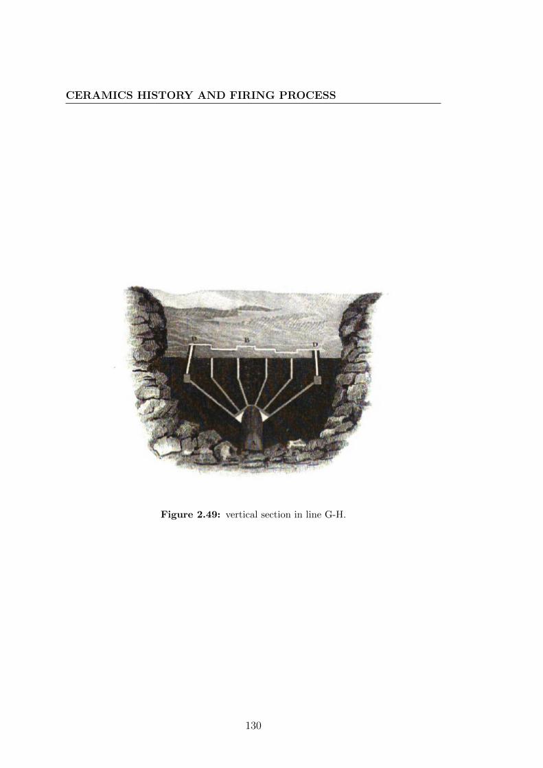
CERAMICS HISTORY AND FIRING PROCESS
Figure 2.49: vertical section in line G-H.
130

STRUCTURE ANALYSIS FOR HISTORICAL KILNS TYPES
its tope became a dam and the loading door, was designed in the structure of
firing chamber. Loading door in the firing chamber was closed after loading by
temporary structure which is opened after firing. Figure (2.50 ) show the major
parts of closed kiln at Pella in Greece during Hellenistic period[5]. Architecture
of these parts was improved to reserve heat, separate between the combustion
materials and ceramics forms and make up-draft circulation for the heat and air.
Organization of kiln parts in its architecture design determined the kind of draft
and air circulation in this kiln. In the figure (2.51 ) the architecture of firing
chamber is similar to the up-draft kiln, but its position is different: the fire box
(A) is in adjacent position to firing chamber (C), not beneath it like it is in the
up-kiln. The wall (B) is for protecting the ceramics forms from combustion gases
and the chimney (D) also take adjacent position in other side of firing chamber.
The architectural design of firing chamber can change the kind of draft of
kiln by closing the top chimney an close the control damper.therefore, the exit
way of gasses are changed from top chimney to two holes in the bottom of firing
chamber. Even the fire box still in its position under the firing chamber as in the
up-draft kiln, but this draft change to down-draft by modification of exit way of
combustion gasses. design and architecture of kiln was adapted by two holes in
the bottom part of wall of firing chamber and control dampers which are added
to structure[112]. Figure (2.52) shows the heat transfer and air circulation where
this architecture allows changing up-draft to down-draft in the same kiln. This
permits to reach high temperature and heavy reduction atmosphere.
The closed kiln required for loading or unloading the objects into or from
the kiln to design a suitable mean for this function. Design door in the firing
chamber functionally can be used to combine between the up-draft and cross-
draft as shown in the figure (2.53). This figure demonstrate front vertical view
(a) and right vertical view (b) of kiln at Klirou on Cyprus[5], where there are
gaps between the bricks or stones that are used to construct the temporary wall
for closing loading door. This technology help in distributing the heat and smock
in reduction firing.
131

CERAMICS HISTORY AND FIRING PROCESS
Figure 2.50: schematic present a vertical section of top dome closed kiln and its
major parts[5]
132

STRUCTURE ANALYSIS FOR HISTORICAL KILNS TYPES
Figure 2.51: schematic present a vertical section of horizontal kiln [5]
Figure 2.52: schematic present a vertical section of Complex Updraft/Downdraft
Kiln from Iran
133

CERAMICS HISTORY AND FIRING PROCESS
Figure 2.53: Schematic present a) front view b) right view of kiln kiln at Klirou
on Cyprus and demonstrate heat transfer in tow draft vertical and horizontal [5].
The treatment during firing or after firing with using kiln technology it be-
came only on the atmosphere of kiln and effects of combustion gasses on chemical
reactions that happened during firing over firing schedule. The limitation of treat-
ment that can be made after firing comes from the difficulties of high temperature
interior the kiln and thermal conductivity of materials that used to construct the
architecture of kiln. These difficulties increase in case of larger kilns. Therefore,
the smaller kiln was used to do treatments after firing process. Raku kiln is an
example of that small kiln that allows making treatment during firing or after
firing where it could be opened, as shown in Chinese kiln in figure (2.54 a) , it is
a muffle kiln which is used for firing the decoration paints over Chinese porcelain
[58]. In China, there is other design of kiln which permits to insert wood inside
during firing, as shown in figure (2.54b), the architecture of this kiln is part of
Elliptical form made from pricks. It has holes in the top that can be used to
lead the firing. The figure (2.55)shows other very important treatment where
it is considered a chemical and physical treatment in same time, in this figure,
there is someone slops water or something which is liquid (s). M. Brongniart
[56] mentioned that this liquid was sloped after reaching high temperature. This
134

STRUCTURE ANALYSIS FOR HISTORICAL KILNS TYPES
Figure 2.54: a) Chinese kiln for firing color and painting glazes b) small Chinese
kiln kiln
treatment as translated from Chinese text was made to create a glassier layer in
the surface of tiles which are produced by this kiln (∫
).
Also the architecture of down-draft Chinese kiln was designed with stock
holes (o) to allow throwing pieces of wood during firing process to reach very
high temperature which required for firing porcelain and the figure (2.56) show
this treatment.
Other example of using architecture of kiln in doing treatment during the
firing is the kiln was discovered in 1975 at Lake of Annecy in Sevrier in France.
This kiln is dated to the end of Bronze Age[29].It is updraft kiln but its firing
chamber dived to two parts as shown in the figure (2.57). The superior part is
135

CERAMICS HISTORY AND FIRING PROCESS
Figure 2.55: Chinese kiln for firing tile and brick with glazes, the glaze layer was
produced by treatment during firing
136

STRUCTURE ANALYSIS FOR HISTORICAL KILNS TYPES
Figure 2.56: horizontal Chinese kiln constructs of two firing chamber
137

CERAMICS HISTORY AND FIRING PROCESS
Figure 2.57: kiln for firing pottery from end of Bronze Age, it is constructed of
two parts [28]
designed to close the firing chamber after loading the kiln and it has the dome
form with chimney in its top. The inferior part is a fixed part.This kiln was small
where the diameter of firing chamber is 0.70 m and the long of mouth of firing
box is approximately 0.25m [113].
The architecture of his kiln permits to produce potteries with black and grey
color, where it is a small kiln and its form distribute smoke and combustion gases
in firing chamber which is closed by superior part. The idea of dividing the firing
chamber in two parts, one of them movable, is a remarkable improvement in
opening fire. The figure (2.58) shows a schematic for this especial design kiln.
Since the arches applications were used in architecture of kilns, the height
building and multi-floor kiln were designed and built. The improvements in
architecture and building technology effected in development of kiln design and
architecture. Where the large horizontal kiln was built in the ellipse form and
138

STRUCTURE ANALYSIS FOR HISTORICAL KILNS TYPES
Figure 2.58: principle of Servrier kiln [29]
139

CERAMICS HISTORY AND FIRING PROCESS
its improvement depends on art and design of architecture. The main structures
that were used in the kiln building were arch, vault and dome, and they were
very important in developing the kiln technology.
The figure shows the architecture of Egyptian kiln that is used to produce
pottery at Maylaouy and Manfalout in Upper Egypt. Figure (2.59) shows (A)
the plan, (B) the front view from outside the kiln and (C) the vertical section
long the line XX of the plan. In general the kiln was built on plan that has
the elliptic form, (F) refer to large stoking chamber that was direct open to the
firing chamber (L) in first floor where the form of two nested domes appear in the
vertical section where the architecture of mouth of stoking chamber (b) emerge,
as well as the reservation holes (ν). The dome architecture was used also to
construct the floor between first level and second one. the holes (l) in dome roof
transfer the heat from firing chamber (L) to firing chambers L′
and L′′
in second
level. Also there was channel (o) that was designed to transfers the heat from
stoking chamber to second level during the wall (M) . Top roof of the kiln was
constructed from three domes that have the holes (c′) in circle form and they
work as chimneys. In the figure the pottery objects (e) was charged for biscuit
firing. The wall of kiln was thicker than Top roof domes [56].
The application of architecture was used to develop horizontal kiln, where it
is form usually take elliptic form and the dividing walls have holes that it con-
structed of arches. The figure (2.60) shows the structure of Saveignies stoneware
kiln. (A) is vertical section at long of axe, (l) first firing chamber where its
temperature is suitable for firing stoneware with l′
the second firing chamber its
temperature is fit for firing the commune pottery. ( B) is a cross section for the
kiln at the dividing wall (∫
) between firing chamber and fire box. (C) is a front
view to the firing box [26].
The architecture in this kiln guided by the idea of transfer of heat and the
role of cross-draft in reaching high temperature which is required for stoneware.
This idea of transfer of heat in horizontal axe of kiln was used to increase the
heat gradually. The horizontal kiln that used for firing stoneware with slat glaze
140

STRUCTURE ANALYSIS FOR HISTORICAL KILNS TYPES
Figure 2.59: Egyptian pottery kiln at Maylaouy and Manfalout in Upper Egypt
141

CERAMICS HISTORY AND FIRING PROCESS
Figure 2.60: structure of stoneware kiln at Saveignies in France
142

STRUCTURE ANALYSIS FOR HISTORICAL KILNS TYPES
required architecture design that allows inserting the salt during firing. Fig-
ure (2.61) shows front and back views and vertical sections of stoneware kiln at
Voissinlieu near Beauvais in France. (A) vertical section at long axe (B) cross
section shows two deferent methods of loading this kiln A and P. (C)front view
of the kiln and show the fire mouth and it take a form of arch. (D) is a back
view of the kiln and (P )door of the firing chamber was appeared in this view.
The form of firing chamber takes the parabolic carve and there are holes (o) in
the tope that work as chimneys and used to insert salt for salting atmosphere of
kiln. The stack chamber (∫
) is over the long of the firing chamber (l) and there
is floor divide between them and it has holes (i) for transferring heat to firing
chamber. (T) is a ground that surrounding the base of kiln. (t) is a flat roof
surrounding firing chamber. Design of this kiln and its architecture were made
to doing treatment during firing that is salting, this idea appear from position of
holes (o) and flat roof (t) in kiln design.
The architecture of climbing kiln in China was improved to multi-chamber or
section for firing. It has a stacking chamber in the front of kiln with fire boxes in
side. This fire boxes with side stoking were designed to reach right temperature
1280 C. due to the fact that wood burn in very high temperature over 1000 C
gives amount of gases , which increase by four times than the same amount when
it burn in temperature less than 400 C [77]. The example of this kiln design was
presented by Naoki Kawabuchi, which called the snake kiln in china. The figure
(2.62) show the view side of this kiln. It is designed to go up over slope its angle
was 6 . The gradient appears in the figure. The interior of the kiln was shaped
seven levels that have a gradient of slope. Each level has shelves for stacking
ware, fire box, and stoking hole. There is a chimney in the rear of the kiln[111]
The architecture was used to design very high building of kiln that is important
to reach very high temperature for firing hard past porcelain. The updraft kiln
was modified to very high building with multi fire box. With appearance of this
kiln design and architecture, the idea of relation between energy of heat which
lose and energy of heat which is generated by combustion was used; therefore the
143

CERAMICS HISTORY AND FIRING PROCESS
Figure 2.61: structure of stoneware kiln that was used for producing salt glazes
, at Voissinlieu near Beauvais in France
144

STRUCTURE ANALYSIS FOR HISTORICAL KILNS TYPES
Figure 2.62: snake kiln that designed by Naoki Kawabuchi , view of the kiln from
side
number of fire box was increased to reach the right temperature. This technology
was used in Europe, the figure (2.63) shows structure design for kiln that was used
to produce porcelain at Lille in France and it is two floors kiln. This kiln used coal
as heat resource. Using coal as heat resource makes change in architecture and
design of fire box. (A) is view from outside of the kiln with cut to show interior of
the kiln, (L) is firing chamber in first floor used for firing glazed forms, (L′) is the
second firing chamber in second floor used for firing clay-body ,( m) a structure
made of iron bars which is used to place the porcelain for firing. This grating
structure composed of horizontal bar supported in the wall and supported from
other side by vertical bar (i),(G ) is exterior wall of the kiln, (T) is a chimney
,(n) is holes which used to transfer the heat to second floor , (s) is a chimney in
the center of kiln to transfer the vault to the second firing chamber (L′) , (S) the
ground of the first chamber which is placed on vault I to avoid the dampness,(g)
gate for receiving the coal, (c) ashtray , (b) mouth of fire boxes ,(k) flanges of
145

CERAMICS HISTORY AND FIRING PROCESS
iron which support circles (a) ,(P) door of first firing chamber and (P′) door of
second firing chamber . (r) is a louver that contacted by part of circle (q) that
turn on point (o) . Other margin of this circle part was connected by wire which
rolls on a pulley (p), other side of wire contacted by jack to open or close the
chimney. In the cross section (B) the plan of kiln is presented at axe which passes
by the gate (g). and the four fire boxes and it is position appear[26].
In factory of Sevres, there was kiln constructed of double floor and wood was
used as source of heat in this kiln. Architecture of this kiln was developed as
shown in front view (A) in figure (2.64). This kiln was used to fire porcelain at
very high temperature. The vertical section (B) at line VV which appear in cross
section (D) that shown in figure (2.65) where (C) shows two half cross section of
the kiln one half at line ZZ and other at line YY in line that appear in vertical
section, and (D) shows two half cross section of the kiln, one half at line XX and
other at line UU that appear in vertical section. There are three firing chamber
L′, L2, L3, each chamber L
′and L2 have four fire boxes (a
′) in first floor and (a2)
in second floor. First firing chamber is closed by vault which has 25 holes (c′) to
transfer heat to second chamber and second firing chamber also is closed by vault
which has the same number of holes (c2)[58], (∫ ′
) are stack chamber in inferior fire
boxes (a′), the flame divided by the gates (g
′) which formed by refractory bricks
in first firing chamber L′.(C
′) is the ashtray ,(e
′) is the place where wood put in
for reaching high temperature in first floor , ( o′) is an open holes which is closed
by tampon of fired clay.(b′) mouth of inferior fire box (a
′) that were opened in
starting firing at low temperature. Same parts repeat in superior floor are marked
by same latter with proponent 2. Firing chamber(L2) is second chamber that used
to very high temperature. (r′) pillar of bricks which to used to load wood to fed
fire boxes (a2)in second floor , this pillar was pierced by vault (d′). T is floor of
second level, (s) entrance of the door (P 2) for second firing chamber( L2), (t) is
iron shutter. (H) is a conical space above firing chamber in third floor (L3) that
used for firing biscuit of porcelain.H′
is chimney. The h is box of iron which is at
terminal of iron bar M and its details shown in figure (2.66). The architecture
146

STRUCTURE ANALYSIS FOR HISTORICAL KILNS TYPES
Figure 2.63: Hard-soft porcelain kiln that used coal at Laill in france
147

CERAMICS HISTORY AND FIRING PROCESS
of this kiln was supported by iron carcass which composed of M is vertical bar
and N is circle . (i) is elastic key which squeeze these circle and it is shown in
figure (2.67).V vide space over ground of kiln ,this space for giving or stopping
the humidity and it appears in cross section (C)[26].
The design of kilns and its architecture were very important in improvement
of ceramics products where these designs are responsible about some of important
factors which effect in three parameters such as :
1. Temperature of firing process where the design of kiln has important role
in temperature that can be achieved by the kiln.
2. Atmosphere of kiln where the air circulation has important role in this
parameter.
3. Treatments that can be done during or after firing where kiln’s design has
important role in this parameter.
148
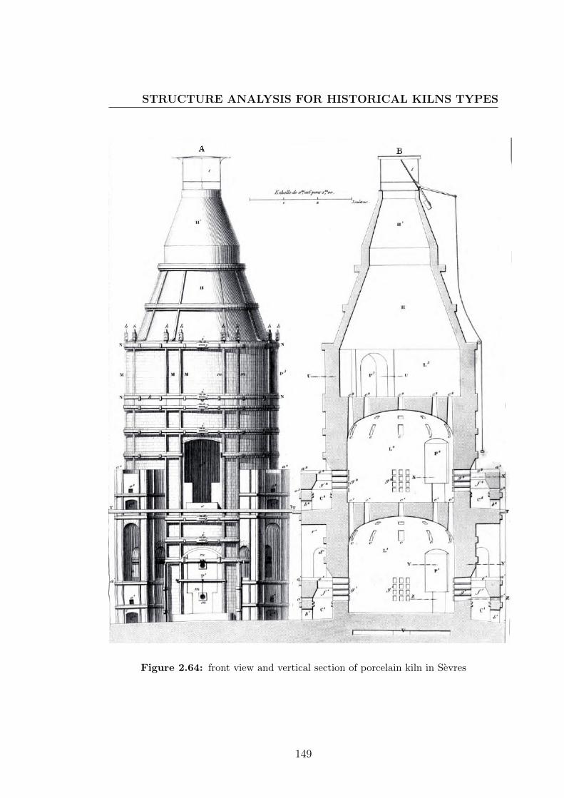
STRUCTURE ANALYSIS FOR HISTORICAL KILNS TYPES
Figure 2.64: front view and vertical section of porcelain kiln in Sevres
149

CERAMICS HISTORY AND FIRING PROCESS
Figure 2.65: cross section in some levels as seen in vertical section of porcelain
kiln in Sevres 150

STRUCTURE ANALYSIS FOR HISTORICAL KILNS TYPES
Figure 2.66: details of iron box which is at terminal of iron bar M
Figure 2.67: details of iron box which is at terminal of iron bar M
151

CERAMICS HISTORY AND FIRING PROCESS
2.5.3 Refractory materials
The pursuance of kilns required materials, since kilns are realistic actually in
these refractory materials. Therefore, improvement in technology of refractory is
related to development of design and producing kilns. This relation comes from
relation between design and materials.
In developments of ceramics firing, inside the earth was used as refractory
materials. This is demonstrated in pit firing. Bricks which were made of clay
also were used as refractory materials to build kilns. The chemical composition
of clay that is used to produce these refractory bricks determined the efficiency
of heat isolation.
The earliest kiln was found in China and it was dated about 30000 B.C. kilns
were common in Egypt and in the Middle East by 10000 B.C. in this era the
natural rocks and clay were suitable to be refractories materials for thousands of
years from earliest kilns, while they were wood-fired. The introduction of coal
and up-draft and down -draft kiln designs increased maximum temperature to
1100 C in 4000 B.C, but stone, clay and fired clay refractoires still served. After
about 5000 year in China, porcelain was being made by 600 A.D, this required
about 1300 C. The firebricks and stone are still used as refractories. In Europe
by 1400 A.D, with using the water-powered bellows and design the vertical kiln
,maximum temperature increased to 1500 and the firebrick and stone still to be
the refractoris materials. In middle of 1830 A.D, the technology of pre-heated air
was used to bring the maximum temperature up to close 1700 C. Blocks or stone
of natural steatite (soapstone) was used to build kilns after this date but fireclay
was used for lower-temperature[32]. The technology of refractory was improved
in twenty century. The refractory materials were classed according to AFNOR
[114] - Association Francaise de Normalisation - classification as flowing:
1. Silica refractories that contain percentage of silica over 91% and percentage
of alumina under 3%.
152
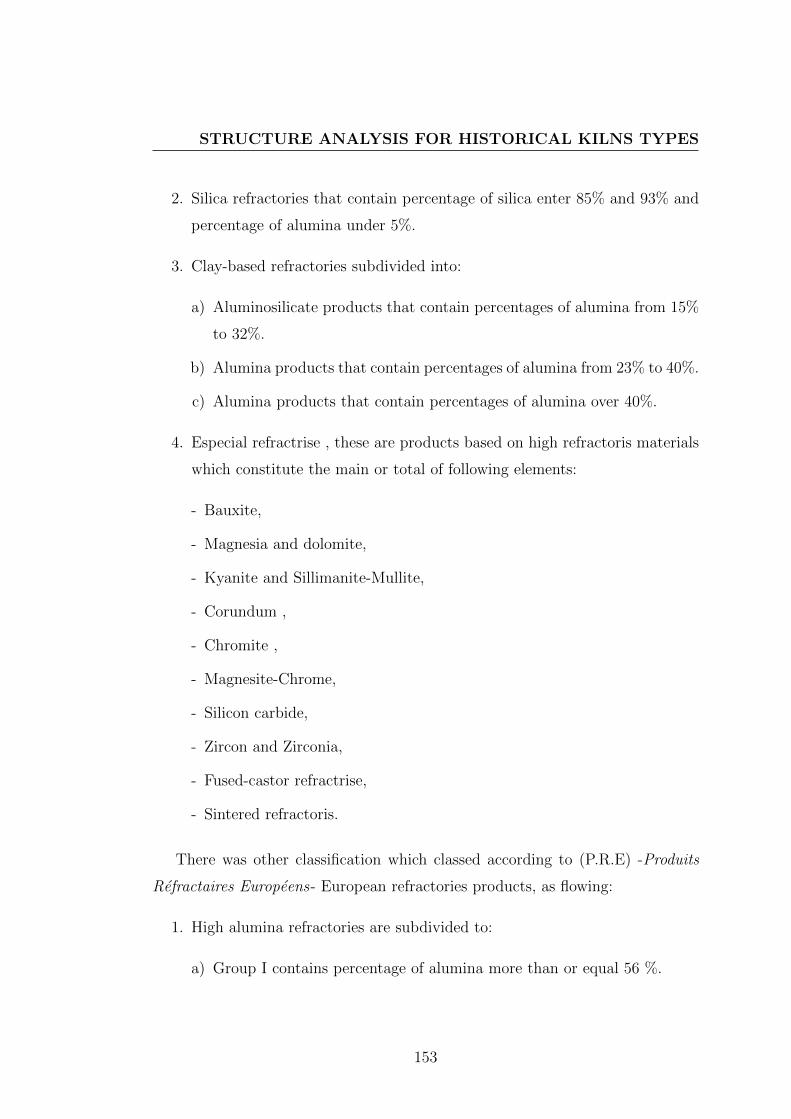
STRUCTURE ANALYSIS FOR HISTORICAL KILNS TYPES
2. Silica refractories that contain percentage of silica enter 85% and 93% and
percentage of alumina under 5%.
3. Clay-based refractories subdivided into:
a) Aluminosilicate products that contain percentages of alumina from 15%
to 32%.
b) Alumina products that contain percentages of alumina from 23% to 40%.
c) Alumina products that contain percentages of alumina over 40%.
4. Especial refractrise , these are products based on high refractoris materials
which constitute the main or total of following elements:
- Bauxite,
- Magnesia and dolomite,
- Kyanite and Sillimanite-Mullite,
- Corundum ,
- Chromite ,
- Magnesite-Chrome,
- Silicon carbide,
- Zircon and Zirconia,
- Fused-castor refractrise,
- Sintered refractoris.
There was other classification which classed according to (P.R.E) -Produits
Refractaires Europeens- European refractories products, as flowing:
1. High alumina refractories are subdivided to:
a) Group I contains percentage of alumina more than or equal 56 %.
153

CERAMICS HISTORY AND FIRING PROCESS
b) Group II contains percentage of alumina more than or equal 45% and
less than 56%.
2. Clay refractories contains percentage of alumina more than or equal 30%
and less than 45%.
3. Siliceous-clay refractory contains percentage of alumina more than or equal
10% and less than 30%,and it contains percentage of silica less than 85%.
4. Semi-silica refractories contains percentage of silica more than or equal 85%
and less than 93%.
5. Silica refractories contains percentage of silica more than or equal 93%.
6. Basic refractoris is classed as flowing:
a) Magnisa contains percentage of MgO more than or equal 80%.
b) Magnesite-Chrome contains percentage of MgO more than or equal 55%
and less than 80%.
c) Chrome-Magnesite contains percentage of MgO more than or equal 25%
and less than 55%.
d) Chromite contains percentage of MgO less than or equal 25% or contains
percentage of Cr2O3 more than or equal 25%.
e) Forsterite is the refractories that its principal constituent is forsterite.
f) Dolomite is the refractories that its principal constituent is dolomite.
7. Especial refractrise, these are products based on carbon, Graphite , Zirconia
, Silicon carbide , Carbide , nitrides.
154

STRUCTURE ANALYSIS FOR HISTORICAL KILNS TYPES
2.5.4 Heating sources
Resources of heat in firing process take its importance in producing ceramics
object from supplied kiln by efficient temperature and create especial atmosphere
inside kiln. Right temperature for firing type of ceramics has a mean role in
the aesthetics of this type of ceramics as well as the atmosphere of kiln. The
ceramicists refer to the type of heat resources or the atmosphere of firing under
their works. Also there were some styles of oriental ceramics that its aesthetics
are created by using especial kind of fuel such as ash glaze firing and Anagama
kiln. The natural of fuel and its chemical constants are affected in atmosphere of
kiln and nature of burning flame.
2.5.4.1 Wood (Table (A.5))
Choosing kind of wood is important where there are different in calories, ashes,
and combustion gases from kind to another. The quantity of water as one of prin-
cipal compositions of wood is different from green stat to high dry stat. carbon,
hydrogen, nitrogen ,oxygen are combustion gases are produced when wood used
as fuel,in addition to some quantities of ashes are produced from firing wood [56].
The flame reaction is an oxidation reaction, therefore atmosphere of kiln when
wood used as a fuel redaction atmosphere by carbon, carbon monoxide, nitrogen,
and vapor of water. The quantity of water in wood has effected by heat in two
manners. These two manners are determined by the temperature of kiln when
wood is thrown inside. Carbon reacts with water vapor superior than 1000 C
to give heat and create Hydrogen reduction atmosphere, while fewer than 1000
C the quantity of water in wood evaporate without chemical reaction. The kiln
technology in China used this reaction to reach the high temperature and create
reduction atmosphere to reduce iron (III). Chinese ceramists used treatments of
throwing wood inside the kiln from stock holes and inserting water or vapor of
water to inside the kiln after achieving 1000 C temperatures [77].Figures (2.55)
and (2.56) show this treatments.
155

CERAMICS HISTORY AND FIRING PROCESS
2.5.4.2 Lignite (Table(A.6))
Lignite, referred to as brown coal. It has low energy density and typically high
moisture content and it has carbon content. Lignite was used for firing hard soft
porcelain at Elbogen in the Czech Republic. It produces a long flame during
firing. are presented in table .From the compositions of three type of lignite, the
kiln which used lignite as fuel, has a reduction atmosphere [56].
2.5.4.3 Coal (Table(A.7))
Coal give calories more than wood and it was used to firing different types of
ceramics in England also was used in Germany and France to fire some ceramics
types . Referring to the time of coal the long flame was required to firing ceramics,
so the larger pieces were preferred in ceramics kilns. Coal fuel required a strong
circulation of air that usually need air supply system , therefore the structure
of kiln that its heat resources is coal, required some modification in fire box
architecture and design. See figure (2.63) . Coal contains high percentage of
carbon, so the atmosphere of kiln is reduction[56].
2.5.4.4 Fuel gases
Fuel gases were used first time to fire hard-soft porcelain 1854. The entrance
of fuel gases to kiln technology affected the efficient temperature, cost of firing,
atmosphere of kiln and structure and lining of kiln. The first experimental of
firing ceramics by fuel gases was depended on creating machines that are used to
transfer the solid fuel to combustion gases and compress them inside the kiln[56].
Using natural gases in kiln technology was important change in the kiln structure
and in its atmosphere. The major composition in natural gas is methane (CH4).
The atmosphere of kiln is light reduction and there is no ashes produced.
156

CONCLUSION
2.6 Conclusion
Atmosphere of kiln can be considered a fixed parameter in most historical firing
technology, where most kilns allow using only one of heat resources. Whatever
this parameter was used to make positive influence. Kind of fuel and its combus-
tion gases made reactive atmosphere, so using same atmosphere en every firing
is related to kiln design and no kiln designed to make changing in atmosphere
by intended manner. From the historical study, the idea of using the atmosphere
of kiln as an effective parameter in treatments on ceramics surfaces is seen to be
indispensable . This study refers to successful aesthetic treatments that were pro-
duced by chemicals reactions between combustion gases and raw materials and
mineral oxides in glaze structure. Also there is other aesthetic treatment that
was made by physical properties which can be controlled during or after firing.
Over timeline in historical study, the atmosphere of kiln passes by two main
technologies, first one is using the atmosphere of kiln; second one is avoiding the
effect of atmosphere of kiln. In the second technology, the structure of glaze and
colored oxides are the changeable parameter which used to create the aesthetic
treatments on ceramic surfaces. In the two technologies, the relationship among
science, art and history is released as shown in figure (2.68) where using the at-
mosphere of kiln is improved with improving of ceramics science and also some
technologies of firing ceramics are neglected. This negligence rustled in disap-
pearance of some aesthetic treatments. Therefore, the contemporary ceramists
reused hysterical method of firing when they want producing some of especial
aesthetic treatments. Science of ceramics was useful in improving historical firing
technology, where the some ideas are improved to create especial aesthetics, as
applying glazes on the ceramics forms then fired them by pit firing technique for
making reaction between glaze structure , fuel materials and other vapor. Also
mixing some chemical powders as copper sulfate with fuel materials is an idea
for creating special colors when pit firing used nowadays. Reflection metallic
colors were produced from nine century by using the carbon atmosphere during
157

CERAMICS HISTORY AND FIRING PROCESS
Figure 2.68: flow chart shows the relationship among aesthetics treatments, ce-
ramics science and history of firing technologies .as a result of historical study.
158

CONCLUSION
firing process, but in nineteen century, M. Theodore Deck [115] propose chemical
formula to make reflection metallic especially red and gold colors by muffle kiln
technology. This formula was suitable to decorate porcelain, where muffle kiln
was created to fire painting of porcelain without effects of combustion gasses.
Therefore, producing golden metallic color in oxidizing atmosphere was required.
With improvements in science of ceramics and its technology, thermal analysis,
chemical structure and physical properties led to inform about the expected re-
action and its time during firing schedule, as they led to design structure of glaze
for reacting with the atmosphere of kiln at right time on firing schedule. The
reaction in right time on firing schedule gives an ability to do reflection metallic
without surfing. Therefore, electric kiln which permit a normal atmosphere is
suitable to modify its design to control the reactions during firing schedule.
The part of historical study guides the scientific part in this research by some
concludes points as following:
1. Firing condition usually was correlated by fuel that used in kiln technology.
2. Available kiln technology determines the possible method of decoration.
3. Carbon, carbon monoxide and carbon dioxide were most gases that effect
in final appearance to ceramics objects.
4. The correlation between the chemical compositions for clay or glazes and
atmosphere of firing process is remarkable in many historical ceramics styles.
5. Structure and architecture of kiln are considered as a mean which enable
or avoid on or more of parameters during firing process.
6. Ceramics kilns were designed to be an oxidizing atmosphere kiln or a re-
duction atmosphere kiln .
159


Chapter 3
Science of Glazes and
preparation for treatment during
or post firing
Hhis chapter deals with scientific information about glaze materials, chemical
reactions , physical properties and design structure of glaze to put in order
with reactive gases or vapor during firing process or to put in order to create
stress in surface of glaze. These scientific information exhibit chemical or phys-
ical performance which required such procedures in specific temperature, and
therefore, different chemical reaction and physical properties control glazes stats
and their final appearance. Design such chemical reactions or physical properties
for producing such appearance or colors required a theoretical about ceramics
glazes. For this purpose, the chemistry state is comprehensively described and
deduced for glaze and its structure with understood coloring mechanism of his-
torical metallic reflection glazes (luster glaze) and ancient Chinese glazes ( five
161

SCIENCE OF GLAZES AND PREPARATION FOR TREATMENTDURING OR POST FIRING
grate wares). The mechanic properties of glaze and its body clay are described
and proposed to control crackle on surface ceramics during firing or after firing.
3.1 Introduction
In ceramic production, firing process is used to give objects solidity and durable
appearance, and during this process there are many chemical reactions oc-
curred. These reactions exist in substrates forms, glazes layers and decoration
enamels. The final appearance of ceramics is determined, based on these reac-
tions. Since ceramists look for such design as final appearance, they can use
chemical reactions of glazes to reach their purpose. Most of aesthetic treatments
are presented in glaze applications, so chemical reactions and physical properties
of glazes are attended to determine particular procedure which is done during
firing process. Glaze is a continuous adherent smooth layer applied to surface of
ceramics forms. These layers varied in transparent or opaque onse. There are
variegated transparent glazes: colorless transparent glaze; and colored transpar-
ent glazes, also there are motley opaque glazes: white opaque glaze and colored
opaque glazes. Therefore, glaze and its compositions are in center attention where
they are in-put materials of chemical reactions.
Accordingly, nature of glaze is important to identify the nature of chemical
reactions which exist during firing process. Nature of glaze differs from before
firing, during firing to after firing. Where before firing, it is a mixture powder of
raw materials, fritted glass or both of them, then it became sediment liquid when
it added to water, and then it became a sediment layer over clay-body. During
firing, at Tg temperature, it transit to glass, then at Ts temperature , it became
a softening glossy layer on hot surface of clay-body, then at Tm temperature ,it
became a melting phase. After firing the nature of normal glaze is a thin layer of
glass(Tg < Ts < Tm) .
162

NATURE OF THE GLAZE
There is an important issue in this research that it must be taken in account
to represent the relation between ceramics art and science ceramics. This issue
based on transformation from final appearance of glaze as glassy state to chemical
formula of this glaze which expresses in different degrees of saturation of normal
silicates[116], from this formula, glaze and some reactions can be designed to oc-
cur during firing process. These reactions added to others factors that effect in
the final appearance and aesthetic of glaze. Therefore, designing proper glazes,
method of applied this glazes and conditions of firing are parameters which ef-
fect in colors and texture of glazes, and in this research the correlation between
condition of firing and glaze structure leads to defined glazes and understand the
relation between the chemical formula and know how it will look when it’s fired
and cooled.
3.2 Nature of the glaze
Glazes, before firing, are relatively thin dried layer commonly < 1 mm in thick-
ness which contains series of inorganic raw materials that is usually applied in
suspension form in water . During firing, glazes compositions react to form glassy
phase, glass particles called frit, ground crystalline ceramics colors and opacifiers,
and processing additive. Also in maturing range, glaze reacts with surface of raw
or biscuited ware in contact zone. After cooling, glazes are thin virtuous smooth
layer of glassy state which consists of a thin layer glass, or glasses and crystals
[16, 69, 117].
Glazes are applied to substrates to provide a shiny, normally smooth surface
that protects the body. The feature of surface may be either matt or bright.
The range of maturing temperature that glazes can be from 600 C to 1500 C
[118], depending on the purpose of applied glaze and the ceramics bodies to
which glazes are applied. Therefore, glazes are similar to glass, where the main
component is silica with other inorganic oxides which are matured in the action of
163
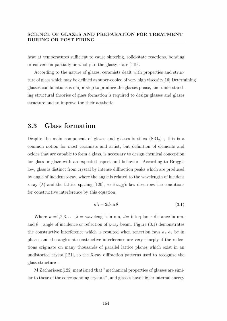
SCIENCE OF GLAZES AND PREPARATION FOR TREATMENTDURING OR POST FIRING
heat at temperatures sufficient to cause sintering, solid-state reactions, bonding
or conversion partially or wholly to the glassy state [119].
According to the nature of glazes, ceramists dealt with properties and struc-
ture of glass which may be defined as super-cooled of very high viscosity[16].Determining
glasses combinations is major step to produce the glasses phase, and understand-
ing structural theories of glass formation is required to design glasses and glazes
structure and to improve the their aesthetic.
3.3 Glass formation
Despite the main component of glazes and glasses is silica (SiO2) , this is a
common notion for most ceramists and artist, but definition of elements and
oxides that are capable to form a glass, is necessary to design chemical conception
for glass or glaze with an expected aspect and behavior. According to Bragg’s
low, glass is distinct from crystal by intense diffraction peaks which are produced
by angle of incident x-ray, where the angle is related to the wavelength of incident
x-ray (λ) and the lattice spacing [120], so Bragg’s law describes the conditions
for constructive interference by this equation:
nλ = 2dsin θ (3.1)
Where n =1,2,3. . . ,λ = wavelength in nm, d= interplaner distance in nm,
and θ= angle of incidence or reflection of x-ray beam. Figure (3.1) demonstrates
the constructive interference which is resulted when reflection rays a1, a2 be in
phase, and the angles at constructive interference are very sharply if the reflec-
tions originate on many thousands of parallel lattice planes which exist in an
undistorted crystal[121], so the X-ray diffraction patterns used to recognize the
glass structure .
M.Zachariasen[122] mentioned that ”mechanical properties of glasses are simi-
lar to those of the corresponding crystals”, and glasses have higher internal energy
164

GLASS FORMATION
Figure 3.1: constructive interference explains the Bragg’s law
than crystals, and therefore glasses consist of three-dimensional random network.
So the glasses and crystals have the same building block, cation polyhedra, but
have different configurations, where the polyhedra, in glasses, are arranged in dif-
ferent patterns not like crystals patterns as shown in figure(3.2),where (a) demon-
strate the atomic structure of composition in crystal form, and (b) demonstrate
the atomic structure of same composition in glass network .
According to atomic arrangement, the oxides which form glasses by themselves
must have four flowing rules which set up by Zachariasen [16, 122]:
1. Each oxygen atom should never be linked to more than two cations.
2. The number of oxygen atoms around the cation must be small 3 or 4.
3. Oxygen polyhedra should share corners,not edges or faces.
4. Three corners at least of each polyhedron must be shared.
Sun[122] suggested that the oxides which have higher single bond strengths are
better to form glasses and they are glasses formers. He calculated the strength of
the M-O single bond in oxide MOx/y by obtained the values for energy Ed which
is required to separate the molecule. table (A.8) presented glasses oxides with
165

SCIENCE OF GLAZES AND PREPARATION FOR TREATMENTDURING OR POST FIRING
Figure 3.2: schematic demonstrate atomic structure of (a) composition in crystal
form (b) composition in glass random network
166

GLASS FORMATION
Figure 3.3: A two-dimensional representation of a sodium silicate glass.
classification to network formers, network modifiers, and intermediate glasses
formers[118].
Therefore, it was found that the SiO2, B2O3, and P2O5 often form glass net-
work formers (NWFs), as well as GeO2 form glass but it is expensive to use in
glaze. The networks which form from glasses oxides have holes that are filled
by some oxides like Na2O, K2O, CaO, MgO and PbO. These oxides called glass
network modifiers (NWMs), they are not glasses former according to Zachariasen
rules and to single bond strength. When (NWM) added to (NWF) , it will be
modified to continuous random network (CRN) ,and the new network was mod-
ified to bridging oxygen link glass forming tetrahedral and non-bridging oxygen
form ionic bonds with the modifiers [16, 123], as demonstrated in Figure (3.3),this
network present example to structure of common glasses.
There are some oxides which not quit form glasses by themselves but when
they are put in glasses network by small amount, they will take place the Si+4
or B+3. This oxides called intermediate glass formers, they can rarely form
167

SCIENCE OF GLAZES AND PREPARATION FOR TREATMENTDURING OR POST FIRING
network itself with some modifiers as in the system (MgO · CaO · Al2O3) or
(K2O · CaO · Al2O3). According the single bond strength, the common inter-
mediate glasses formers are Al2O3, PbO, ZnO, ZrO2 and CdO[16].
Therefore, glaze is glass network which was formed by SiO2, B2O3 or P2O5
formers , this network is modified by limited percentage of CaO ,Na2O or sub-
stitutions for both of them, and some glasses forming ions in glaze continuous
random network is replaced by Al2O3. Practically, this continuous random net-
work is prepared from raw materials to treat by heating after it is applied on
surface of ceramics body.
The position and the ratio of such oxide inside network affect the properties
of glaze and its aspects. Therefore, design reactions to occur during firing process
have to be that reaction with oxides which fill in the holes of network because
it has the low bond strengths in the network. Cycle of heating treatment has
an affects in network arrangement, the reaction that can be done after forming
the network is interesting in this research. The network of glaze capable to has
one or more crystalline phases that compressed with glossy phase, so the relation
between different phases: glass, crystals, and liquid is required to expect the
changed in phases when some treatments were done during the firing process.
3.4 The Volume-Temperature Diagram
The network of glaze capable to has one or more crystalline phases that com-
pressed with glossy phase, so the relation between different phases: glass, crys-
tals, and liquid is required to expect the changed in phases when some treatments
were done during the firing process.
Specific volume is competing against temperature to describe the relation
between different phases in volume-temperature diagram figure (3.4),where a melt
is cooled from point a which is a temperature higher than melting temperature
Tm , at point b, the volume V shrinks along the line ab. Although point b is
168

GLAZE CALCIFICATION
the thermodynamic freezing point in case of melt or the thermodynamic melting
point Tm of a crystal of the same composition. The crystal occur only if there is
sufficient nucleation rate I which is followed by a significant crystal growth rate u.
these two rates are zero at Tm so there is no crystallizing at Tm, but the two rates
increase in the shades region in figure (3.4) with increasing the super-cooling, so
in this region there is highest probability of crystallization. In case of crystal at
some point in shaded region, the mass shrinks in volume infrequently without
changing in its temperature, this the first-order thermodynamic transition, the
shrinking continues along the line (de) with cooling. If one of two rates I or
u disappear at point b, the liquid passes the monotonically into a super-cooled
liquid state without the appearance of crystals. [123]
According to this diagram ,and to the nature of glazes that have glassy phase
and one or more of crystals phases, the treatments which can be made during
firing to react with crystal phase consider to exist in temperature rang at some
points in shaded region. Also any reaction was targeted to affect in aesthetic
of glaze; its structure should have one or more of reactions components. Most
of reactions that can be done in surface of glazes are with metal oxide. The
aspects of crystalline glaze required a sufficient nucleation rate; this condition is
provided in this case by added ZnO or TiO2 to glaze structure, and a significant
crystal growth rate condition is provided by slowly rate cooling. Without these
two conditions the aesthetic treatment that is shown in figure (??) cannot exist.
3.5 Glaze calcification
The glazes wither they are used in industrial or in artistic field, have been classi-
fied into some groups. These classifications are important to design glaze, where
they varied into translucent layer and opaque layer. There are variegated translu-
cent glazes: colorless translucent glaze; and colored translucent glazes, also there
are motley opaque glazes: white opaque glaze and colored opaque glazes.
169

SCIENCE OF GLAZES AND PREPARATION FOR TREATMENTDURING OR POST FIRING
Figure 3.4: The volume-temperature diagram.
170

GLAZE CALCIFICATION
The application of glazes, in order to decorate ceramic bodies, makes another
variation in glaze types. When pattern of colored glazes applied under layer of
transparent glaze, this type of glaze called under-glaze, and if this pattern applied
over layer of opaque glaze, this kind of glaze called over-glaze. In applied ceramic
arts, the term of glaze is not limited to its nature: transparent, opacity, colored or
colorless, but also glazes are classified according to types of ceramic bodies which
are decorated by these glazes. Clay bodies classified into some groups based on the
temperature, and therefore, glazes are divided up according at which temperature
they are matured. In this way, glazes divided to three main groups: low tem-
perature (1050 C-1150 C) for earthenware objects, medium temperature (1200
C - C1220) for stoneware bodies and high temperatures (1250 C-1280 C) for
stoneware and porcelain forms[124].It is worth to mention that the temperature
of firing is mustered by standard parametric cones. Table (A.9) provide temper-
ature equivalent for Orten standard large cones. American ceramic society, and
table (A.10) provide temperature equivalent for Seger standard cones. Staatliche
prozellan-manufaktur, Berlin[67]. These tables refer cone number which indicates
to equivalent maturing temperature. Glazes are classified also by cone numbers
which demonstrate the wide firing range.
The composition of glaze was used to classify glazes, where they are divided
into led glazes and leadless glazes; this may be a classification according to nature
of the flux. Based on the composition of glazes, they are varied from alumina
to silica ratio or the acid to base ratio, and the acidity number or acid equiv-
alent. Therefore, there are lead-silicate glazes, lead-boro-silicate glazes, alkali-
boro-silicate glazes and alkali-lime-silicate glazes[125]. The feature bright or mat
of glaze is related to alumina to silica ratio. Glazes also can deviates, based on
composition, to frit glazes and raw glazes.
In this research, aesthetic aspects is desired, and therefore, the appearance
of glazes and their decorations will take in account as first selection from glaze
classification, the chosen glaze will applied on various ceramics substrates, hence,
in which temperature ceramic bodies are fired is important decision to select right
171

SCIENCE OF GLAZES AND PREPARATION FOR TREATMENTDURING OR POST FIRING
glaze. Also the classification by temperature is useful to put glazes layers in order
especially in case of multi glazes decoration (over-glaze or under-glaze).
Glaze calcification, its applications, chemical structure and relation between
them are required for designing a glaze structure, as they are a pressing desired.
Especially in this thesis, design glaze is necessary to prepare chemical reactions
and physical properties at final phases of glazes from first step of design these
glazes. A structure of glaze which can react with atmosphere of kiln or can be
reactive to such procedure during firing is the main target in this scientific study.
3.6 Design the glaze structure
In this research, aesthetic aspects is desired, and therefore, the appearance of
glazes and their decorations will take in account as first selection from glaze
classification, the chosen glaze will applied on various ceramics substrates, hence
in which temperature ceramic bodies are fired is important to select right glaze.
Therefore, wide firing range of glaze is taken an account when ceramist designs
the glaze. In case of multi glazes decoration (over-glaze or under-glaze), order of
glazes layer on surface of ceramic body is related to order of wide firing range
for each layer. Then most feature aspects of glaze are designed by added one or
more oxide to structure of glaze.
3.6.1 Expression of glaze structure
There are three ways that are used to write structure of glaze recipe, percentage
analysis and unity formula. The recipe of glaze presents a list of raw materials
quantities which compose the glaze, sometimes there are glasses forms which
called frits are used in components of glazes recipes. The technique of fritted
glaze is used with materials which are soluble in water such as boric oxide. Also
for reasons of health , the lead is used in commerce glazes as frit[16]. Usually
172

DESIGN THE GLAZE STRUCTURE
fritted glazes are used in whitewares, but nowadays frit technologies are used in
many types of ware. Some of most available glaze frits corporation are: Ferro, O-
Hommel, Pemco, Fusion, and General. Substations among frits brands from this
corporation ar shown in table (A.11), and Ferro standard glaze frits are shown in
table(A.12).
Batch recipes of glazes are measured quantities percentages of raw materials
which mixed together by weight. They are prepared to be ready for application.
For some considerations as location, availability, costs, and mineral impurities
raw materials are selected for manufacturing of glaze. The form of batch recipe
is written in two columns one refers to raw materials or fritted glass and the
other refer to the weight of these materials in gram for small scales or kilogram in
large scales. Therefore, this expression of glaze structure is the practical applica-
ble form which especial experience and notion bout the raw materials and frits.
Percentages analysis which is one of three methods to write glazes structure are
used to showing percentage of each individual oxide in recipe batch, where there
total are 100 %. These percentages write in two columns one for the oxides and
other one for percentage of oxide. These percentages analysis can be obtained by
two ways; first is chemical analysis for traditional or ancient’s glazes that is made
by one of different methods; the second is a converting from unity formula. The
important of this method comes from that it is required to convert from chemical
formula to batches recipes[126].
The third way of writing glaze structure is Seger formula, where it is method to
describe a glaze by its various chemical components, where Seger formula is a de-
scription for relations between component oxides, and molar equivalent is used to
describe quantities of molecules which compose the glaze. Seger formula classifies
the oxides to three groups: network former / acid oxides molecules (RO2; R2O5),
network modifiers/ basic oxides (R2O; RO) and network stabilizers /amphoteric
oxides (R2O3). There are some rules regulate composition in equivalents. The
sum of the bases R2O and RO in the glaze is equal to 1 and is contrasted with the
number of acid oxide molecules and amphoteric oxides molecules[18, 116]. Some
173

SCIENCE OF GLAZES AND PREPARATION FOR TREATMENTDURING OR POST FIRING
actual used glazes are described by Seger formula with limited compositions, these
were: RO = 1.0, SiO2 = 1.5-3.0 for earthenware and fin French faience, RO =
1.0, AL2O3 =0.1-0.4 SiO2 = 1.5-3.0 for German and English white-wares and RO
= 1.0, AL2O3 =0.5-1.25 SiO2 = 5.0-12.5 for porcelain[127].
These three methods of writing glaze structure are important to transfer the
glazes structures from a collection of raw materials to a collection of molecules
that react during firing with other element, molecules or complex molecules under
control conditions that was constructive in design and expected such reaction
to enrich aesthetes of glazes. This transformation from raw materials to unity
formula is required to design these chemical reactions with retaining of glasses
network and glazes properties, where these designs are made in Seger formula
and then it can be transfer to batch recipes which are practical and applicable.
3.6.2 Calculation glaze structure from other structure
Percentage analysis of oxides can be converted to proposal batch recipe when the
chemical analysis of raw materials is known. Percentage analysis of oxides for
such glaze with the molecular weight for each raw materials which will used to
give this oxide, and with knowing the chemical reactions to this raw materials ;
the quantities of one or more oxides can be calculate by molecular weight . The
sum of molecular weight for each molecule that are given by one raw material
is equal to molecular weight that required of this raw materials, by comparison
between molecular weight of each raw material and total molecular weight of all
raw materials in batch recipe the percentage of batch recipe will be defined.
The converting unity formula to percentage analysis is calculated from num-
bers of molecules in unity formula, where multiplying the number by its molec-
ular weight gives the weight of each oxides. So weight of formula is equal sum
of weights for all oxides in glaze, then dividing weight of each oxide by weight
formula to define the percentage analysis. Mathematical program - MapelTM
-
174

DESIGN THE GLAZE STRUCTURE
was used to do this calculation just by put the number of oxides instead of x1
,x2. . . . . . . . . . . . ..xn in program windows that showing in the figure (3.5).
The converting from percentage analysis unity formula is calculated by divid-
ing the percentage analysis value for the oxides by the molecular weight of oxides
and then the results well are divided by the weight of flux group (RO, R2O)
the results are number of unity formula. Figure (3.6) shows MapleTM program
window that are used for converting an analysis to Seger formula.
These calculations permit to transfer chemical analysis of ancient glazes to
Seger formula which permits to understanding physical properties and chemicals
reactions and allow reproducing these glazes and improving its structure to enrich
its surfaces aesthetically. Also unity formula is used to design glaze structures by
calculating the ratios between acid group, stabilizer and fluxes group.
3.6.3 Glaze structure designed by unity formula
The main ingredient in glaze is silicate and it takes salts form of dibasic silicic acid
H2SiO3,actually the two hydrogen atoms are replaced by univalent metal oxide
R2O ,bivalent metal oxide RO or trivalent metal oxide R2O3.The normal silicates
have different degrees of saturation which can be expressed as following[116]:
R2SiO3, e.g.,K2SiO3 or K2O · SiO2,
RSiO3, e.g.,CaSiO3 or CaO · SiO2,
R2(SiO2)3, e.g.,Al2Si3O9 or Al2O · 3 SiO2.
But the second degree of saturation of silicates are expressed in following formula:
R4SiO4 =
{R2O. SiO2R2O
}Semisilicate
R6SiO5 =
{R2O. SiO22 R2O
}Sesquisilicate
175

SCIENCE OF GLAZES AND PREPARATION FOR TREATMENTDURING OR POST FIRING
Fig
ure
3.5
:w
ind
owof
Map
leT
Mp
rogr
amth
atu
sed
for
conver
tin
gu
nit
yfo
rmu
lato
an
an
aly
sis.
176

DESIGN THE GLAZE STRUCTURE
Fig
ure
3.6
:w
ind
owof
Map
leT
Mp
rogr
amth
atuse
dfo
rco
nver
ting
anan
aly
sis
tou
nit
yfo
rmu
la.
177

SCIENCE OF GLAZES AND PREPARATION FOR TREATMENTDURING OR POST FIRING
R2Si2O5 =
{R2O. SiO2Si2O
}acide or doublesilicate
Above formula expressed just a second degree of saturation of silicates, while
glazes have extremely complex compositions of silicate. Glaze can be designed
as natural minerals by represented its compositions in formula. The main con-
siderations in design formula of glaze structures are the ratio between valence
of acids and bases, sum of bases = 1 and is contrasted with the number of acid
oxides and stabilizer oxides[116]. Therefore, designing glaze structure based on
understanding the relation between these ratios and its features. Glaze withe
composition K6Ca7Al10Si40O105 can be described by following formula:{0 · 3 K2O0 · 7 CaO
}0.5Al2O3. SiO2
The process of design the glaze by unity formula based on two procedures,
first one is a determining which oxide molecule well be in the formula of glaze and
determining in which group it will be : a glasses former, an intermediate former
or a modifier, second procedure is determining valence of each group and of each
oxide molecule.
The glazes classification by their composition is used to determine some oxides
in glaze formula, where there are lead-silicate glazes, lead-boro-silicate glazes,
alkali-boro-silicate glazes and alkali-lime-silicate glazes. SiO2 oxide is an essential
component in glazes; sometimes B2O3 and P2O5 are used with SiO2 as network
formers, however, the B2O3 acts as powerful flux and it is used to decrease the
viscosity of molten glaze. Therefore boric oxide in the glaze formula means a
good smooth and brilliant carving to this glaze[22, 128, 129]. Also boric oxide
used in formula to avoid crazing and to transfer the gaze from transparent glaze
to opaque glaze especially when it is added in certain ratio with silica[130].In
small amount P2O5 forms colloidal particles which lead to create a type of light-
reflective quality called colloidal opacity, and thus, phosphorus oxide is usually
used in slight amount in glaze. It is likely to give them a bluish flush[22]. Also
178
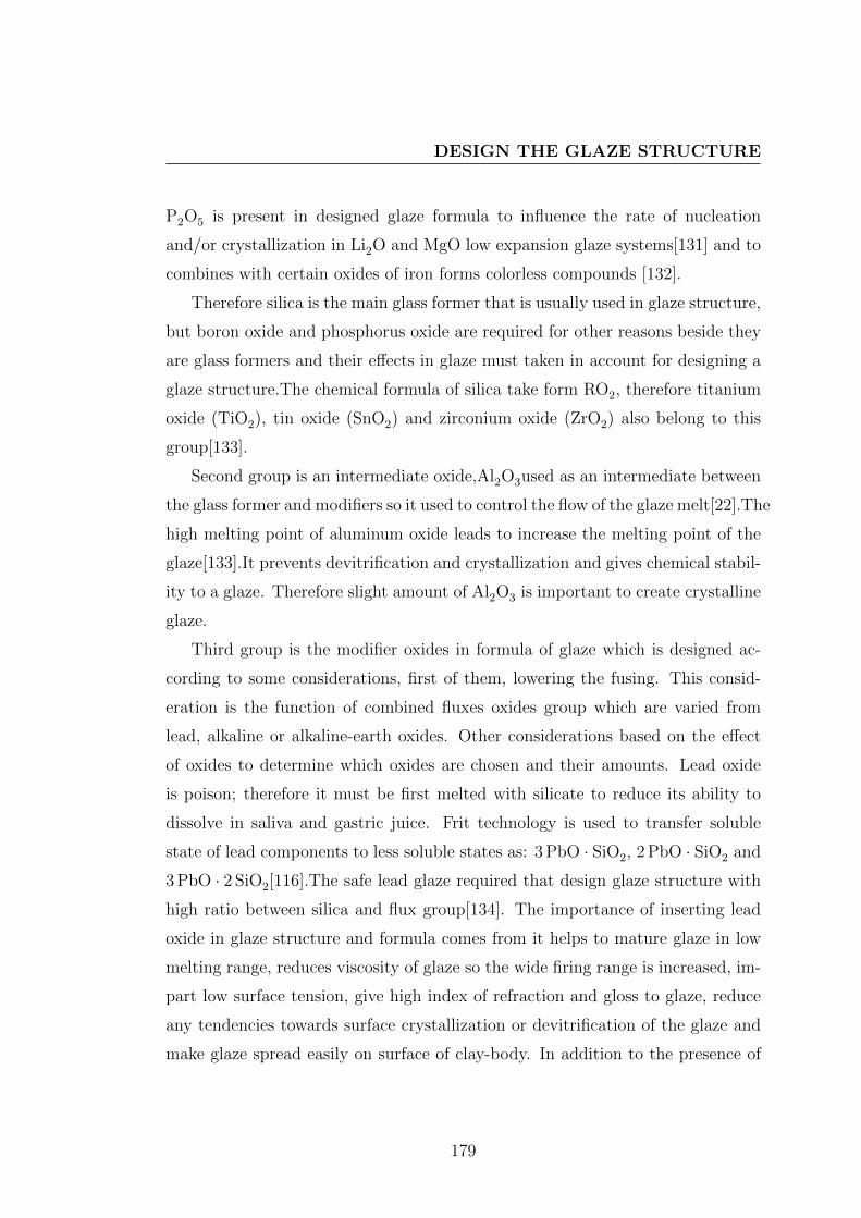
DESIGN THE GLAZE STRUCTURE
P2O5 is present in designed glaze formula to influence the rate of nucleation
and/or crystallization in Li2O and MgO low expansion glaze systems[131] and to
combines with certain oxides of iron forms colorless compounds [132].
Therefore silica is the main glass former that is usually used in glaze structure,
but boron oxide and phosphorus oxide are required for other reasons beside they
are glass formers and their effects in glaze must taken in account for designing a
glaze structure.The chemical formula of silica take form RO2, therefore titanium
oxide (TiO2), tin oxide (SnO2) and zirconium oxide (ZrO2) also belong to this
group[133].
Second group is an intermediate oxide,Al2O3used as an intermediate between
the glass former and modifiers so it used to control the flow of the glaze melt[22].The
high melting point of aluminum oxide leads to increase the melting point of the
glaze[133].It prevents devitrification and crystallization and gives chemical stabil-
ity to a glaze. Therefore slight amount of Al2O3 is important to create crystalline
glaze.
Third group is the modifier oxides in formula of glaze which is designed ac-
cording to some considerations, first of them, lowering the fusing. This consid-
eration is the function of combined fluxes oxides group which are varied from
lead, alkaline or alkaline-earth oxides. Other considerations based on the effect
of oxides to determine which oxides are chosen and their amounts. Lead oxide
is poison; therefore it must be first melted with silicate to reduce its ability to
dissolve in saliva and gastric juice. Frit technology is used to transfer soluble
state of lead components to less soluble states as: 3 PbO · SiO2, 2 PbO · SiO2 and
3 PbO · 2 SiO2[116].The safe lead glaze required that design glaze structure with
high ratio between silica and flux group[134]. The importance of inserting lead
oxide in glaze structure and formula comes from it helps to mature glaze in low
melting range, reduces viscosity of glaze so the wide firing range is increased, im-
part low surface tension, give high index of refraction and gloss to glaze, reduce
any tendencies towards surface crystallization or devitrification of the glaze and
make glaze spread easily on surface of clay-body. In addition to the presence of
179

SCIENCE OF GLAZES AND PREPARATION FOR TREATMENTDURING OR POST FIRING
PbO in the glaze lead to reduce the chemical stability[116, 134], therefore it is
powerful in structure of reduction glazes to enhance effect of reduction firing.
The alkaline oxides, Na2O, K2O and Li2O also used to reduce the fusion point
and they support the solution of other oxide in glazes. Potassium nitrate KNo3
as source of K2O in finale formula of glaze is used to eliminate small bubbles on
account of the generation of oxygen.The alkaline-earth oxide used in design glaze
formula for different causes, where CaO is used to make glaze strong and shiny,
but if it is added in large amount it lead to devitrification and crystallization
of glaze. Barium oxide BaO can be used in formula of glaze instead of lead and
calcium oxide, where it give the glaze an appearance like lead glaze with strength,
hardiness and low cost ,but it must use in frit for avoiding the toxicity of barium
compounds [116]. For producing leadless glaze or lead free glaze the bismuth
oxide, zinc oxide, or strontium oxide are used as an alternative of lead oxide
in the formula of glaze structure[134].The color elements and oxides are usually
oxides of transition metals elements, also the rare-earth elements can be used as
glaze colored[16].
The oxides that compose the glaze structure formula are ordered in Seger
formula as following: R2O/ROBaseF lux
.
R2O3
AmphotericStabilizer
.
RO2AcidGlass former
Determining the relative numbers of oxides molecule is complex process in design
glaze structure, where there are many factories must be taken in account for
determining relative number to one glaze formula. According the temperature or
cone of firing there some limitation for relatives numbers in formula are supposed,
where the oxygen ratio(this the ratio between the total moles of oxygen and the
total moles of glass former,as present in equation (3.2), it is from 2 to 3 for all
glazes)[16] and mole ratio for alumina Al2O3 in formula can give idea about firing
180

DESIGN THE GLAZE STRUCTURE
temperature.
Oratio =Moloxygen
MolSi +MolB(3.2)
The approximate temperature of heat treatment for glaze structure can be
estimated from Seger formula depending on Lengersdorff flux factors. The F is
flux factor which is calculated from equation (3.3)[17].
F =
∑Sifi∑Sjfj
× 100 (3.3)
Where Si refers to the molar fraction of the oxides having the value of Lengers-
dorf factors fi > 0.4 and Sj is the molar fraction of the oxides having the value of
Lengersdorf factors fj < 0.4 which are presented in table(3.1) with other specific
coefficients used for glaze preparation. The FT temperature of heat treatment is
calculated from equation (3.4)[17]:
FT =161.21789− F
0.10252(3.4)
F calculated with equation (3.3) FT is heat treatment ( C).
The equation (3.3) and Lengersdorff flux factors indicate that PbO(2.00) is
the first oxide which decrease the temperature of heat treatments for glaze and
it is immediately followed by B2O3 and Sb2O3 , SiO2,TiO2 and Al2O3 are the
oxides which increase temperature of heat treatments , and Na2O and K2O have
the equal effect in decrease the temperature of heat treatments and ZnO and BaO
have equal effect also. Therefore, Lengersdorff flux factors are specific determi-
nants of relative numbers for each oxide form oxides that be chosen to create the
glaze structure. There is other important specific determinant which depends on
the ratio between Al2O3 and SiO2 or glass former. This ratio determine the gloss
and shiny aspect for glaze and this ratio varied according to a temperature of
heat treatment to glazes.
Figure (3.7) show the relation between Al2O and SiO2 ratio in cone 10∼1305 C,
cone 12 ∼ 1326 C, cone 14 ∼ 1366 C and cone 16 ∼ 1450 C, the ratios between
181

SCIENCE OF GLAZES AND PREPARATION FOR TREATMENTDURING OR POST FIRING
Table 3.1: Characteristics and specific coefficients used for glaze preparation[18]
Oxide Molar Winkelmannand Dietzel partial Lengersdorff Appen
Weight Scott partial coefficients flux coeffi-
coefficients factors cients
Na2O 62 333.3 0.7 0.88 1.590
K2O 94.2 283.3 0.7 0.88 1.575
MgO 40.3 003.3 6.6 0.54 1.610
CaO 56.1 166.7 4.8 0.58 1.730
ZnO 81.4 060.0 4.7 0.60 1.710
BaO 153.3 100.0 3.7 0.60 1.880
Al2O3 102 166.7 6.2 0.32 1.520
Fe2O3 159.7 133.3 - 0.7 -
B2O3 69.6 003.3 0.8 1 1.470
SiO2 60.1 026.7 3.4 0.38 1.459
TiO2 79.9 136.7 4.1 0.38 2.080
P2O5 141.5 066.7 - - -
MnO 70.94 - - 0.6 -
silica and alumina are chosen to be in the areas of brightness, mat or semi-mat
and not be in the areas of over-fired, immature, and crazed [16]. Sometimes in
ceramic art studio those avoided ratios are recommended for producing especial
features on surface of ceramics forms. To design the formula of glaze also a specific
coefficient which was determined by Appen for oxides can be used for calculating
the refraction coefficient (n)from this equation :
n =∑
aini (3.5)
where ni are Appen coefficients see table(3.1)and ai represents the weight fraction
of oxide. The values of refraction index show that the PbO and TiO2 are highest
oxides which affect in refraction coefficient, where n(PbO) is 2.42[18, 135]. This
182
DESIGN THE GLAZE STRUCTURE
Figure 3.7: diagrams domestrate the relation between SiO2, Al2O3 ratio and
brightness of porcelain glazes at coins 10,12,14 and 16.
values are considered in designing glaze structure. According to the rule of lead
oxide in the refraction property of glaze, its effect in creating metallic reflection,
and to toxic effect, the Thorpe’s Ratio is used to control lead solubility. Thrope
recommended the empirical equation (3.6) to predict the solubility of lead frit,
where the value of equation(3.6) should not exceed 2 [134].
Mols of Basic+Mols Alumina
Mols of Acidic Oxides× 223
60, (3.6)
this equation was stated as following :
Ro+ Al2O3
RO2
= 0.5(As Maximum), (3.7)
183
SCIENCE OF GLAZES AND PREPARATION FOR TREATMENTDURING OR POST FIRING
This ratio is used to calculate the additive of lead oxide in the frit or glaze, and
it should be equal 0.5 or less for recommending this glaze for table-ware[134].
The mechanical properties of glazes can be controlled also by limiting and
designing the formula of glaze, where the coefficient of thermal expansion and
Young’s modulus of glaze are effected by chemical composition of glaze. Mechan-
ical properties are considered properties to affect the aspects of glaze especially
crazing and cracking treatments on surface of ceramics objects.
Young’s modulus (E )of glaze is approximately calculated according to flowing
equation(3.8):
E =∑
aiEi, (3.8)
where E the elasticity modulus; ai the weight fraction of each oxide component
and Ei the Winkelmann and Schott coefficients for each oxide component as
presented in table (3.2 [18].
(TEC) the coefficient of thermal enpension for such glaze can be closed to
calculate according equation(3.9):
α =∑
aiαi (3.9)
where ai represents the% molar for different oxide component and αi represents
coefficient of thermal expansion for different oxide component[18].
Glaze formula should be designed to has a thermal expansion coefficient(TEC)
that is adequate with a thermal expansion coefficient(TEC) of the body-clay. The
surface treatments of glaze after firing are taken in account where crackle treat-
ment is required some different between glaze and clay-body thermal expansion
coefficient, while the smooth no cracking treatment is required the equality or at
least the value of the difference (TEC) between body and glaze is not more about
5 × 10⁻⁷K−1 [136].
Design Seger formula for glaze structure is relative to expect the aspects of
ceramics objects, where aspects of glaze related to its chemical components. Also,
this formula is relative to explain aspects of historical ceramics types according to
184

DESIGN THE GLAZE STRUCTURE
their chemical analysis.A visualization about technologies of these types can be
created from this explanation and it is benefit for reproducing or improving these
types. The formula of glaze organizes components oxides which are considered as
in-put of chemical reactions which is treated by heat inside the kiln. During this
heating process the out-put of chemical reactions can be created or controlled to
affect on the aesthetics of glaze as demonstrate in figure (1.18).
Table 3.2: Factors for calculating Young’s modulus from chemical compositions
[19]
Oxide Winkelmann and schott (94)
A∗ B§ C¶
Na2O 6.0 9.8 6.9
K2O 3.9 6.9 2.9
MgO - 3.9 2.9
CaO 6.9 6.9 -
ZnO 5.1 9.8 -
BaO - 6.9 2.9
Al2O3 17.6 14.7 12.7
Fe2O3
B2O3 - 5.9 2.5
SiO2 6.9 6.9 6.9
TiO2
P2O5 - - 6.9
PbO 4.5 - 5.4
As2O5 3.9 3.9 3.9
∗Factors under A are fore glaze or glasses free from B2O3,P2O5,BaO,MgO.§Factors under B are for glaze or glasses free from PbO,P2O5.¶Factors under C are for borosilicates, lead borosilicates,and phosphates.
185

SCIENCE OF GLAZES AND PREPARATION FOR TREATMENTDURING OR POST FIRING
3.7 Scientific researching on technology of an-
cient ceramics
According to historical styles of ceramic art which are mentioned in chapter three,
study on the glaze structure of these styles and their chemicals elements assists
in designing the suitable glaze formula which is fundamental for establishing
treatments during firing for enriching aesthetic of glaze. These treatments can
be chemical or physical, therefore in this thesis, metallic reflection from Islamic
ceramics and Ru kiln from Chinese ceramics are ideal styles that helps in estab-
lishing kiln as a tool for enriching the aesthetics of ceramics forms during or post
firing.
3.7.1 Chemical treatment
After maturing the glaze, the network of glass is modified by network modifiers
and colored oxides which reacted with atmosphere of kiln to influence in the
final appearance. The most effects which happened during the firing process are
produced in carbonized atmosphere. Both of metallic reflection and colors of
five grate kilns in song dynasty are treated by carbon during firing as chemical
treatment.
3.7.1.1 Firing process of some famous Chinese porcelain
The glaze colors of the superior Ru porcelain are sky green and sky blue, the
inferior are spawn white, powder green, pea green, shrimp green and verdant. The
variation of all these colors are produced depend on firing technology, where there
are some scientific studies which used to discover the scientific and technological
aspects of Ru kiln and the other famous porcelain from the Chinese Song dynasty.
Chen Songhua [137] studied the specimen of raw material of sky-green glaze
186
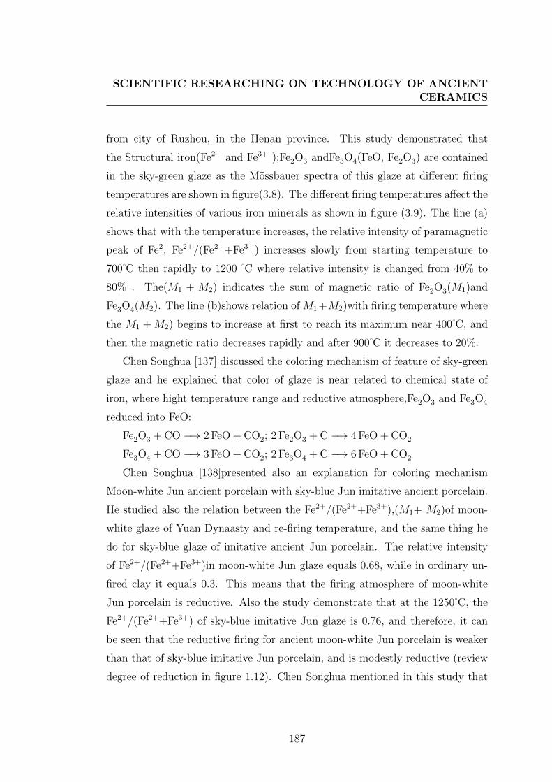
SCIENTIFIC RESEARCHING ON TECHNOLOGY OF ANCIENTCERAMICS
from city of Ruzhou, in the Henan province. This study demonstrated that
the Structural iron(Fe2+ and Fe3+ );Fe2O3 andFe3O4(FeO, Fe2O3) are contained
in the sky-green glaze as the Mossbauer spectra of this glaze at different firing
temperatures are shown in figure(3.8). The different firing temperatures affect the
relative intensities of various iron minerals as shown in figure (3.9). The line (a)
shows that with the temperature increases, the relative intensity of paramagnetic
peak of Fe2, Fe2+/(Fe2++Fe3+) increases slowly from starting temperature to
700 C then rapidly to 1200 C where relative intensity is changed from 40% to
80% . The(M1 + M2) indicates the sum of magnetic ratio of Fe2O3(M1)and
Fe3O4(M2). The line (b)shows relation of M1 +M2)with firing temperature where
the M1 + M2) begins to increase at first to reach its maximum near 400 C, and
then the magnetic ratio decreases rapidly and after 900 C it decreases to 20%.
Chen Songhua [137] discussed the coloring mechanism of feature of sky-green
glaze and he explained that color of glaze is near related to chemical state of
iron, where hight temperature range and reductive atmosphere,Fe2O3 and Fe3O4
reduced into FeO:
Fe2O3 + CO −→ 2 FeO + CO2; 2 Fe2O3 + C −→ 4 FeO + CO2
Fe3O4 + CO −→ 3 FeO + CO2; 2 Fe3O4 + C −→ 6 FeO + CO2
Chen Songhua [138]presented also an explanation for coloring mechanism
Moon-white Jun ancient porcelain with sky-blue Jun imitative ancient porcelain.
He studied also the relation between the Fe2+/(Fe2++Fe3+),(M1+ M2)of moon-
white glaze of Yuan Dynaasty and re-firing temperature, and the same thing he
do for sky-blue glaze of imitative ancient Jun porcelain. The relative intensity
of Fe2+/(Fe2++Fe3+)in moon-white Jun glaze equals 0.68, while in ordinary un-
fired clay it equals 0.3. This means that the firing atmosphere of moon-white
Jun porcelain is reductive. Also the study demonstrate that at the 1250 C, the
Fe2+/(Fe2++Fe3+) of sky-blue imitative Jun glaze is 0.76, and therefore, it can
be seen that the reductive firing for ancient moon-white Jun porcelain is weaker
than that of sky-blue imitative Jun porcelain, and is modestly reductive (review
degree of reduction in figure 1.12). Chen Songhua mentioned in this study that
187

SCIENCE OF GLAZES AND PREPARATION FOR TREATMENTDURING OR POST FIRING
Figure 3.8: The mossbauer spectra of the sky-green glaze raw material at different
firing temperatures
188

SCIENTIFIC RESEARCHING ON TECHNOLOGY OF ANCIENTCERAMICS
Figure 3.9: Changing of Fe2+/(Fe2++Fe3+)of the paramagnetic peak
and magnetic ratio (M1+ M2) with firing temperature in sky-green glaze
(a)Fe2+/(Fe2++Fe3+)(b)(M1+ M2)
189

SCIENCE OF GLAZES AND PREPARATION FOR TREATMENTDURING OR POST FIRING
Figure 3.10: the relative contents of coloring elements in Ru glaze
the coordination number (CNs) of Fe2 and Fe3 in moon-whit Jun glaze are de-
termined to be both 4. Iron is the colorant in Jun glaze and its chemical state is
one of factors that affect the glaze color.
Zhang Bin [139] studied the relation between glaze color and its wavelength
(λD), where the concentrations of 30 coloring elements in glaze of ancient Ru
porcelain are determined by neutron activation analysis (NAA). Figure(3.10)
shows the relative contents of coloring elements in glaze, the relative content
of iron accounts for about 96% of the total contents of all coloring elements. The
Mossbauer spectrum of glaze at room temperature are shown in figure(3.11) and
it demonstrate that the magnetic components are little enough to be ignored but
the paramagnetic components ,that is Fe2+ or Fe3+ ions presented in the glaze
structure and the ratio of Fe2+ / Fe3+ determines the glaze color. The table (3.3)
represents the Fe2+ / Fe3+ ratio ,wavelength (λD) and glaze color for some several
samples ancient Ru porcelain,and the relation between wavelength and the Fe2+
/ Fe3+ ratio is shown in figure (3.12). Fe2+ / Fe3+ determines the glaze color.
190

SCIENTIFIC RESEARCHING ON TECHNOLOGY OF ANCIENTCERAMICS
Figure 3.11: Mossbauer spectrum for a sample of Ru glaze at room temperature
Figure 3.12: The relation diagram between Fe2+ / Fe3+ ratio and wavelength
(λD) of glaze color of ancient Ru kiln
191
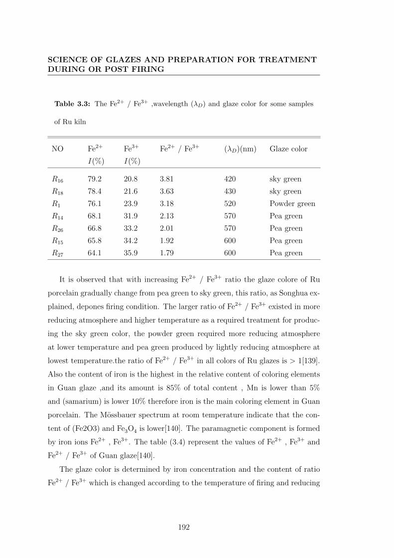
SCIENCE OF GLAZES AND PREPARATION FOR TREATMENTDURING OR POST FIRING
Table 3.3: The Fe2+ / Fe3+ ,wavelength (λD) and glaze color for some samples
of Ru kiln
NO Fe2+ Fe3+ Fe2+ / Fe3+ (λD)(nm) Glaze color
I (%) I (%)
R16 79.2 20.8 3.81 420 sky green
R18 78.4 21.6 3.63 430 sky green
R1 76.1 23.9 3.18 520 Powder green
R14 68.1 31.9 2.13 570 Pea green
R26 66.8 33.2 2.01 570 Pea green
R15 65.8 34.2 1.92 600 Pea green
R27 64.1 35.9 1.79 600 Pea green
It is observed that with increasing Fe2+ / Fe3+ ratio the glaze colore of Ru
porcelain gradually change from pea green to sky green, this ratio, as Songhua ex-
plained, depones firing condition. The larger ratio of Fe2+ / Fe3+ existed in more
reducing atmosphere and higher temperature as a required treatment for produc-
ing the sky green color, the powder green required more reducing atmosphere
at lower temperature and pea green produced by lightly reducing atmosphere at
lowest temperature.the ratio of Fe2+ / Fe3+ in all colors of Ru glazes is > 1[139].
Also the content of iron is the highest in the relative content of coloring elements
in Guan glaze ,and its amount is 85% of total content , Mn is lower than 5%
and (samarium) is lower 10% therefore iron is the main coloring element in Guan
porcelain. The Mossbauer spectrum at room temperature indicate that the con-
tent of (Fe2O3) and Fe3O4 is lower[140]. The paramagnetic component is formed
by iron ions Fe2+ , Fe3+. The table (3.4) represent the values of Fe2+ , Fe3+ and
Fe2+ / Fe3+ of Guan glaze[140].
The glaze color is determined by iron concentration and the content of ratio
Fe2+ / Fe3+ which is changed according to the temperature of firing and reducing
192

SCIENTIFIC RESEARCHING ON TECHNOLOGY OF ANCIENTCERAMICS
Table 3.4: The Fe2+ / Fe3+ ,wavelength (λD) and glaze color for some samples
of Guan glaze
NO Fe2+ Fe3+ Fe2+ / Fe3+ (λD)(nm) Glaze color
I (%) I (%)
G27 75.8 24.2 3.13 540 Powder-green
G25 75.2 24.8 3.03 540 Powder-green
G26 75.1 24.9 3.01 560 Powder-green
G4 74.0 26.0 2.85 560 Powder-green
G3 73.0 27.0 2.70 560 Powder-green
G6 70.8 29.2 2.43 570 Grey-green
G5 55.2 44.8 1.23 620 Grey-green
G15 52.6 47.4 1.11 700 cream
atmospheres of the kiln , where the firing under changeable reducing condition at
specific temperature.there fore the colore of glaze Guan was produced as result
of using the firing condition to control the aesthetic treatment.
These discovering about historical firing technology, that affect the colors of
glazes even the glaze structure was the same, indicate to the possibility of using
the the kiln as a tool to enrich the aesthetic treatment of ceramics glaze during the
firing when the chemical reaction of iron oxides with carbon is possible to occur
and to leave iron ions Fe2+ , Fe3+ in the network of glass or glaze. The ratio of
this ions in the glaze determines the color of glaze according color phenomena for
glaze. Also this discovering is considered as as important for reproducing these
styles of ancient ceramics that have hight artistic value.
193

SCIENCE OF GLAZES AND PREPARATION FOR TREATMENTDURING OR POST FIRING
3.7.1.2 Firing process of metallic reflation decoration
Historical study demonstrate the importance of kiln atmosphere, thermal paths
and glaze composition for producing luster glaze and metallic reflation since the
early 9th century AD and their technologies are transferred to Egypt, Syria and
through the Mediterranean basin. Due to the artistic value of ceramics forms that
are decorated by luster and metallic reflation colors, this technique continued to
be produced in Europe until the sixteenth century depending on kiln technology
of reduction atmosphere.
In this technology chemicals reactions between CuO(CuII), Cu2O(CuI) and
Ag2O with reducing gases which almost in traditional technology are carbon ox-
ides. These reaction create metallic film in network of glass and produce especial
optical properties. This copper and/or silver deposition was applied in historical
tradition luster technology by putting a mixture salts and oxides of copper and
silver, together with vinegar ochre, and clay on glazed surface and then heated to
about 600 C in carbon reductive atmosphere as sudan reactions during re-cool
path of firing schedule [11, 96].
There are some scientific studies which tried to explain this technique and
to divined the parameters that affected in colors or metallic aspects of luster
decoration. In this technique the collided ions of cooper Cu+,Cu2+and silver Ag+
are embodied in glass matrix, and with sufficient reduction atmosphere they are
changed to metallic state which remained trapped inside the glaze within first
layer. The metal particle size is between 5nm and 50nm, and therefore, the luster
seems to be a nanosized metal-glass, this metal particles forme a layer in varying
thickness from 100 nm to 1 µm. The average between pure copper to pure silver
was observed in luster layer. Cu/Ag ratio indicated to different color[11, 96, 141].
The concentration of copper and silver in the glaze show the significant affects
in color of luster glaze, where yellow and green is related to silver rich and orange,
brown and red is related to copper rich. Bobin [13], in his study about the role
of copper and silver in coloration of metallic luster, refers to the decoration with
194

SCIENTIFIC RESEARCHING ON TECHNOLOGY OF ANCIENTCERAMICS
green color and ocher-yellow have more silver than copper and the Ag /(Cu+Ag)
ratio between 52-92%. While the ratio of Cu /(Cu+Ag) in range between 65-90%
led to produce brown and ocher-yellow color, but also the Ag /(Cu+Ag) ratio
lead to ocher-yellow as exit in samples from Kairouan , Mesopotamia and Sicily.
Figure (3.13) shows a binary diagram which demonstrates the normal situation of
atomic percent Cu /(Cu+Ag) and Ag /(Cu+Ag)ratio in green, brown, and ocher-
yellow metallic luster decoration. These ratio is important when Seger formula
of glaze or decoration are designed to limit the relative number of CuO, Cu2O
and/or Ag2O. The tables (A.3and A.4) shows chemical composition of Kairouan
, Mesopotamia glazes. Padovani [11] discovers that the glaze with gold luster
decoration ,on samples of XVI century pottery from Deruta, contains silver in
average approximately 20 wt.% . This percentage appears to be diffused within
glaze which also include a small amount of copper 1-3 wt.%. The red luster
contains average of copper which is estimated about 8 wt.%. The state of copper
in glass matrix are Cu+,Cu2+and no metallic state in gold luster and the relative
concentration of tow states are estimated that 40% of copper is in the oxidation
state Cu+ ,and 60% is in state Cu2+. The 20% of copper in red luster was metallic
phase and 80 % is in the Cu+ state. The Seger formula of renaissance glaze, which
its composition analysis was presented by Padovani, is:{0, 49− 0, 61K2O0, 39− 0, 51PbO
}. 0, 11− 0, 16Al2O3 .
{2, 45− 6, 24SiO20, 11− 0, 15SnO2
}The glaze structure influences in the the state of copper, where the Cu+ is mainly
exchange with Na+, and also copper-alkali ion exchange existed in glass that
contains both Na+ and K+. The luster reflection form as a frits step from copper-
and silver-alkali ion-exchange and then followed by nucleation and growth of metal
nanoparticles,the crystal size is related functionally to the depth inside the glaze
that is result of exchanging the Cu+ and Ag+ ions from raw paint applied on
glaze with Na+and K+from the glaze ant that flowed by the crystal formation of
copper nanocreystals in glaze matrix [11, 142].
195

SCIENCE OF GLAZES AND PREPARATION FOR TREATMENTDURING OR POST FIRING
Figure 3.13: Binary diagram demonstrates the relative concentration of Cu
/(Cu+Ag) and Ag /(Cu+Ag) ratio in luster decoration from Kairouan Iraq and
Sicily, and it demonstrates the relation between this relative concentration and
color
196

SCIENTIFIC RESEARCHING ON TECHNOLOGY OF ANCIENTCERAMICS
Mechanism of ionic exchange in glaze and glass was concerned the driving force
responsible fore diffusion of silver and copper ions into glaze layer. Therefore the
contents of Na+ and K+ in glaze structurer is method to control the diffusion of
Cu+ and Ag+ that play role in determining the color of metallic luster, as it is
discovered from the analysis of early Islamic luster from Iraq, and of later Hispano
Moresque luster from Paterna. The molten salt of copper and silver as sulfates
or nitrates help atomic exchange and replacement of alkalis of glaze by copper
and silver ions. This explain the use of sulfur containing compound in luster
bach recipes, where cinnabar (HgS) was added to luster metallic recipes in XIII
century AD with silver sulfide that to create a sulfo reducing atmosphere which
is necessary to reduce the silver and copper. The cinnabar (HgS) at temperature
above 400 C to provide sulfur (S) which make sulfo reducing atmosphere of firing.
Using cinnabar instead of sulfur to produce sulfo atmosphere transforms CuO
into Cu2O and forms silver or copper sulfates and sulfides, but the two later
decomposes in high temperature to leave the final phase metallic copper and
silver in the glaze. Therefore the role of cinnabar is producing the sulfo reducing
condition between 500 C and 600 C that helps in reducing the copper to Cu+,
and to avoid the reduction of silver to its metallic state before it has imped inside
the glaze [96]. Therefore the duration and time of reaction during firing and kiln
technology are important to achieve intentional chemicals reaction in finale phase
inside glaze to determine the aesthetic treatment of glaze.
The diffusion of coloring elements inside the glaze layer depends on the ex-
change ion mechanism between colors and glaze, therefore the continents of alkali
oxides in glaze structure is related to affect of colored. The content of potassium
in gold-like lustier decreases from 1.7% to 0.5% K2O, and from 2.8% to 1.5%
K2Oin copper-like luster[143].
Bobin [13] demonstrated an important factor in the diffuse coloration of metal-
lic luster decoration beside the relative concentration of Cu˚and Ag˚ which is the
refractive index of glaze. in addition to the role of radius of the colloids in the
glaze. Therefore the structure of glaze and process of design glaze are important in
197
SCIENCE OF GLAZES AND PREPARATION FOR TREATMENTDURING OR POST FIRING
enriching the aesthetic of ceramics decoration by metallic luster colors. This raise
the attention to the role of local environment which surround Cu+,Cu2+,Ag+and
/or metallic stat of this minerals ions inside the glaze.
Gold-like metallic decoration as a luster glaze which was studied from Spanish
and Italian styles show that the metallic film indicates the presence of 1-10% of
copper and silver. The copper-like luster exhibited Cu /Ag molar ratio > 1, while
the gold-like luster exhibited Cu /Ag molar ratio < 1. Metallic film of element
copper and silver was protected against re-oxidation in air atmosphere after firing
by glassy layer from glaze with thickness varying in the rang of 10-20 nm [92].
generally, there are some parameters to control the mechanisms of metallic
luster formation that should be taken in account when designing the structure of
glaze, as glaze oxides are considered in-put of chemical reactions and the kiln per-
mit to this reactions the conditions to exist. This parameters can be concluded in
Cu/Ag ratio as it is the color elements, glaze structure and it oxides, atmosphere
of kiln and bath of thermal treatment.
The ratio between silver and copper colorant, wether it was applied in the
paint raw or with glaze structure , can be designed to be in range that was
discovered by historical and scientific study. Seger formula or oxide analysis can
be used to calculate the raw materials in order to apply this discoveries in ceramic
industrial and ceramics arts.
State of silvers an copper ions inside the glaze have important role the color
and its aspects. The applicable method to control this states are related to kiln
technology and glaze structure, where the reduction atmosphere is responsible
about transfer silver and coper raw materials in applicable recipes to metallic or
ions phases after firing, while the glaze structure is responsible about behavior
of silver and copper ions inside the glaze when it was in glassy state. Alkali
ratio inside glaze structure is important in this factor. Also, the refractive in-
dex of glaze is determined by glaze structure, and the equation (3.5) with the
details about the values of refraction index coefficients of oxides which presented
in table(3.1) are used to calculate the refraction coefficient of glaze which can
198

SCIENTIFIC RESEARCHING ON TECHNOLOGY OF ANCIENTCERAMICS
be controlled by designing glaze structure. Another important point in applied
reflection metallic luster is the temperature of reduction which is necessary to
chemicals reactions between carbon atmosphere and metallic oxides, and the soft
state of glaze during these chemical reactions are necessary to ensure the adher-
ence of luster. Therefore the relation between the temperature of reaction and
soft state of glaze is an issue to applied metallic luster by using kiln technology.
This issue include two methods first is perpetrate the glaze structure according
its heat treatment by using equations (3.3 and 3.4) with the value of Lengersdorf
factors from table(3.1), second is retention and controlling the conduction of kiln
during period of chemical reaction until passing soft point of glaze or paint. The
size of colloidal and metallic crystal in glass network is related to firing cycle
especially in significant crystal growth rate which is referred in section (3.4). So
the technology of metallic luster is divided between glaze design and treatments
during firing including atmosphere of kiln and firing cycle.
3.7.2 Mechanical treatment
The main aesthetical treatment which is produced on glaze surface by mechanical
treatment is the crackle. It had appeared in the twelfth century in China during
the Song Dynasty (960-1279), in some styles of five famous Chinese porcelain. As
well as metallic reflection, the crackle is considered as a treatment which exists
during firing process. The stress which can be created in glaze layer after glaze
maturing can used to create the crackle on surface of glaze. This stress depends
on some parameters which is should explained to understand the mechanism of
creating net crakes in Ru kiln from China, and also to introduce a new method for
enriching the aesthetic of glazes surface by crack net. Some historical documents
mentioned that Guan crackle was induced by formulating the glaze to shrink
more than the clay body, that caused the glaze to fracture. Ru crackle was
got by added grains of agate to its glaze [77]. Chinese culture web sites and
online Museums [144, 145] mentioned to an historical knowledge which said that
199

SCIENCE OF GLAZES AND PREPARATION FOR TREATMENTDURING OR POST FIRING
Zhang Shengyi produced Ge Kiln covered by many crackles, and his technique to
create this crackle is accidentally cooled when the porcelains were still too hot.
Crackling technique produced in Europe in nineteenth century from 1920 to 1940
when atelier de faıence was created , and the sculpture introduced for its new
aesthetics in Sevres, made in small batches covered with polychrome enamel or
cracked.
From historical study the crackles could be created by preparation glaze struc-
ture or by thermal shock during firing process, and scientifically, this is possible.
Most of modern crackles technology based on glaze composition where some meth-
ods of producing crackle coating in Russia are invented by design glaze batch
containing 12-20 % gypsum (CaSO4 · 2 H2O)and preparing to low-meting [146].
Another type of crackle coating includes perlite (Na2O·K2O·Al2O3·SiO2), bo-
rax (Na2O · 2 B2O3 · 10 H2O), zinc oxide (ZnO), and chalk (CaCO3). The decora-
tive effects of this coating are based on the emergence of crazing after the article
is fired, immersed in water, and then immersed in pigment solution and fired.
Also other type of crackle coating includes concentrated nepheline, but in order
to obtain decorative crackle coating, it is necessary to restrict oneself to the three
specified compositions with a firing temperature of 1000 - 1100 C [146]. All of raw
materials, gypsum (CaSO4 · 2 H2O) and nepheline (K2O.3 Na2O.4 Al2O3.9 SiO2)
, which are used in this inventions are sources of some network modifiers/ basic
oxides that have high value of thermal expansion coefficient CaO, K2O and Na2O,
so the net cracks which presented on these coating after firing is considered to be
related to thermal expansion coefficient of glaze and the the expansion of gases
which are be in the glaze layer in form of bubbles that are produced from previous
raw materials. The high thermal expansion coefficient of glaze and mechanical
phenomena are prospered in this crackle coating.
The composition of glaze determines thermal enpension(TEC) of glaze from
equation (3.9) which is suggested by Winkalmann and Schott. Glazes are homoge-
nous amorphous solid solution so the values of TEC of glaze are additive function
200

SCIENTIFIC RESEARCHING ON TECHNOLOGY OF ANCIENTCERAMICS
of glaze composition at specified temperature rang. The β-factor of volume expan-
sion coefficient(K−1) calculated from α-liner thermal expansion coefficient(K−1)
as this equation[147]:
β ' 3α =∑
aiβi (3.10)
where βi - volume expansion coefficient of the individual compound (K−1) and
ai amount of compound in the glaze (wt.%). The relation between TEC of glaze
and appeared crackle on surface of glaze related to the relation between the
TEC coefficient and tensile and higher compression stress in glaze. This stress
ont related to TEC of glaze only but also the TEC of ceramic body also, and
ceramic (clay body) itself belongs to the group of polycrystalline, multiphase
materials.The thermal expansion coefficient of ceramic body can be calculated
also from additive the function of the TEC of individual solid phases, crystalline
and/or amorphous phases, and their volume fraction in material[147]. The cracks
forming on glaze if Tensile or higher compression stress are released in the glaze.
The compression stress (+σ)arises in the glaze if:
σglaze − σbody > 0 (3.11)
and the value of compression strength of common glazes is in range of 80-320
MPa,where the glaze stress σglaze is calculated from equation (3.12) and body
stressσbody is calculated from equation (3.13)which they are suggested by Salmang
a Scholzeso this compassion stress exist with the TEC of the glaze is lower than
that of the ceramic body[136, 147].
σglaze =(αbody − αglaze)×∆T
1−µglazeEglaze
+1−µbodyEbody
× dglazedbody
(3.12)
σbody =(αglaze − αbody)×∆T
1−µbodyEbody
+1−µglazeEglaze
× dbodydglaze
(3.13)
The tensile stress (-σ)arises in the glaze if:
σglaze − σbody < 0 (3.14)
201

SCIENCE OF GLAZES AND PREPARATION FOR TREATMENTDURING OR POST FIRING
and the value of tensile strength of common glazes is in range of 40-160 MPa,where
the glaze stress σglaze is calculated from equation (3.12) and body stressσbody is
calculated from equation (3.13) so this tensile stress exist with the TEC of the
glaze is higher than that of the ceramic body.
σ ( stress unit is Pa), α (linear thermal expansion coefficient unite is K−1),
d - thickness of body and/or glaze coat, E – elasticity module (Eglaze,Ebody 60 ×
109 N/m2) as it can be calculated from equation 3.8, µ – Poisson constant (≈
0.20; for the body and the glaze).
The normal glaze has better resists to compression stress than to the tensile
stress. Compression stress load capacity of the glaze is 10-15 times higher than for
the tensile stress. In fact, The recommended gentle compression stress that glaze
can resist without cracks, is about 15-20 MPa, because it has positive influence
on the mechanical strength of product. Such stress is arisen in glaze to create
crackle when the TEC of the body is about 5 × 10⁻⁷K−1 higher than the TEC
of the glaze [136, 147].
The excess of the value of compression or tensile strength of the glaze leads
to its cracking just during the cooling of the glazed ware, as well as immediately
after the firing in case of using the glaze structure to generate tensile or high
compression stress. The ∆T which can increase the stress in glaze before the
finale part of cooling.
From this theoretical description the parameters that effect on crackles treat-
ment on glazed ceramics are: the value of TEC difference between biscuit and
glaze, elasticity module for glaze and biscuit, glaze thickness (usual 150 - 250
µm), nature of glaze-biscuit interface which forms during the firing, firing tech-
nology especially for glazes and cooling rate during firing process. Therefore the
technology of crackle is related to glaze structure, glaze and clay forming and
application , and firing technology. These can be explained in, the both of ther-
mal expansion coefficient, young modulus Poisson constant are related to glaze
202
SCIENTIFIC RESEARCHING ON TECHNOLOGY OF ANCIENTCERAMICS
structure, biscuit thickness and glaze thickness are related to clay and glaze ap-
plications and forming, thermal shock or hight cooling rate which can be done
during firing process.
When scientific studies attempt to discover mechanisms for color and crackle
of five famous grate Chemise porcelain or metallic reflection luster , some descrip-
tions of applicable treatments are apposed for artist and ceramists, and they can
do them to use the kiln as a tool for creating especial aesthetic. This propositions
consume between preparing materials to be ready to such chemical reaction or
physical change, designing tools or kiln to permit the conduction of this chemical
reaction or physical change,and prepping the glazes as a medium which have to be
suitable for permitting to this reaction exists and allow to nanocreystals which
are produced by this treatment. Therefore the main rustle from this previous
chapters are chemical reaction and physical properties of glazes materials and
kiln technology.
203


Chapter 4
Scientific and Excremental Basics
for Treatments During Firing
This chapter presents the feedback for using designs of glazes structures to
prepare materials based on the different chemical reactions which is proposed
during firing process. These materials are designed in order to react with carbon
and sulfur in atmosphere of kiln. Phase diagram of iron ores and Ellingham
Diagram are used to explain what is expected from chemical reactions during
the firing, also the temperature of reactions is determined from this diagrams.
The relation between temperature of reaction and firing schedule leads to better
treatment. Therefore this scientific study lead to prepare condition and materials
that was required to create one or more of glaze colorant, based on chemicals
reactions between glaze and atmosphere of kiln. Experimental study to simulate
Ru kiln body and glaze was made to prepare materials for new kiln. Thermal
shock was experimented as treatment during firing,and the theoretical desecration
for doing thermal shock inside the kiln was proposed.
205

SCIENTIFIC AND EXCREMENTAL BASICS FOR TREATMENTSDURING FIRING
4.1 Introduction
Fore using the condition of firing to make such aesthetics treatment on ceram-
ics surface, the procedures and applications are required. These procedures are
included in materials and condition, especially to obtain especial aesthetic treat-
ment on glazed forms. The applicable procedures for materials are based on these
simulation for historical materials which cane contribute in reducing the research-
ing area about materials that are applicable to give good results. In frits step for
re-using the the kiln and its technology for achieving especial aesthetics. Modern
technology and science are responsible about providing theory of improving the
idea, methods of application and tools of productions.
Ores of iron can be considered as colorant crystals that are crystalized after
reducing the iron and copper oxide to ionic and/or states and then react with
sulfur vapor inside the kiln in such temperature as demonstrate in phase diagram
of Cu−Fe−S, see figure (4.23). Ellingham diagram instructs to the priority of
chemical reactions between the carbon or sulfur and glazes oxides, and it can
give clear image about thermodynamics reactions during firing. This order of
reactions used to design glaze structure and design inserting carbon or sulfur
into the kiln. The Coanda effect∗ and cold air front§ phenomenons are used to
apply the thermal shock treatment during firing. The heat transfer and thermal
conductivity explain the faction of this treatment.
∗The Coanda effect, also known as ”boundary layer attachment”, is the tendency of a stream
of fluid to stay attached to a convex surface, rather than follow a straight line in its original
direction. The principle was named after Romanian discoverer Henri Coanda, who was the first
to understand the practical importance of the phenomenon for aircraft development.§A cold air front is the place where a cold air mass replaces a warm air mass when different
air masses do not mix because they have different temperatures and densities, and this happens
because the warm air is lighter than cold air which is dense and heavy
206

SIMULATION STUDY FOR SOME ANCIENT CERAMICS
Accordingly, the treatments that design of kiln is improved to apply them are
classified to thermal shock treatment, and chemical chock treatment.
4.2 Simulation study for some ancient ceramics
Clay body and glaze of Ru kiln porcelain, from China in the late Northern Song
Dynasty (1086-1125)[101], are simulated for understanding the historical tech-
nique which are used to produce crackle on surface of Ru kiln forms, for es-
tablishing method to design unity formula and choose raw materials for body
and glazes which are fundamental in using kiln as tool for enriching aesthetic of
ceramics during firing, and for indicating to the application of these aesthetics.
4.2.1 porcelain body
The data which are used for simulating clay body of Ru kiln porcelain was ob-
tained from ” Proton induced X-ray emission (PIXE) analysis of sources of porce-
lain body of Ru Guan and Jun Guan porcelains ” study , where M.Gouxia et la
studied the chemical analysis of 50 samples of Jun kiln porcelain body and 34
samples of Ru kiln porcelain body to know the origin of raw materials of Jun
Guan Porcelain by comparison with Ru Guan porcelain. The table (4.1) presents
major chemical elements for samples which are used in simulation of Ru porce-
lain body. These samples are chosen depending on the percentages of oxides in
34 samples of Ru kiln which are presented by Gouxia study[101]. The samples
which have higher and lower percentage of Al2O3, SiO2, K2O, CaO, TiO2, MnO,
Fe2O3 oxides from Gouxia study, were calculated for simulation. Therefore, 11
sample from Ru kiln samples are chosen (R40b, R41b, R42b, R43b, R44b, R271b,
R275b, R330b, R333b, R339b, R382b).
207

SCIENTIFIC AND EXCREMENTAL BASICS FOR TREATMENTSDURING FIRING
Tab
le4.1
:M
ain
chem
ical
oxid
esof
Ru
Gu
anp
orce
lain
bod
y(R
GP
D)
Cod
e(P
IXE
)oxid
esan
aly
sis
Com
pen
sati
ng
oxid
esan
aly
sis
No
Nam
eB
od
yco
lor
Al 2
O3
SiO
2K
2O
CaO
TiO
2M
nO
Fe 2
O3
LO
IA
l 2O
3S
iO2
K2O
CaO
TiO
2M
nO
Fe 2
O3
R40b
RG
PD
ash
ygra
y27.5
665.7
41.7
70.5
21.1
50.0
21.7
31.5
127.9
866.7
51.8
00.5
31.1
70.0
21.7
5
R41b
RG
PD
ash
ygra
y26.2
166.0
62.1
80.7
31.0
80.0
22.2
41.4
826.6
067.0
52.2
10.7
41.1
0.0
22.2
7
R42b
RG
PD
ash
ygra
y28.0
365.2
51.7
30.3
81.2
80.0
21.8
11.5
028.4
666.2
41.7
60.3
81.3
00.2
1.8
4
R43b
RG
PD
ash
ygra
y30.1
662.2
61.5
21.4
71.0
50.0
42.0
01.5
030.6
263.2
11.5
41.4
91.0
70.0
42.0
3
R44b
RG
PD
ash
ygra
y26.8
665.7
71.9
00.4
21.1
30.0
22.3
91.5
127.2
766.7
81.9
30.4
21.1
50.0
22.4
3
R47b
RG
PD
ash
ygra
y30.1
161.8
42.1
71.3
51.1
30.0
11.8
81.5
130.5
762.7
92.2
01.3
71.1
50.0
11.9
1
R271b
RG
PD
ash
ygra
y26.7
766.2
61.8
20.4
41.2
70.0
01.9
41.5
027.1
867.2
71.8
50.4
41.2
90.0
01.9
7
R275b
RG
PD
ash
ygra
y26.6
666.3
11.8
60.6
01.2
30.0
11.8
41.4
927.0
667.3
11.8
90.6
11.2
50.0
11.8
7
R330b
RG
PD
ash
ygra
y31.7
560.9
41.7
70.8
41.1
00.0
02.1
01.5
032.2
361.8
71.8
00.8
51.1
20.0
02.1
3
R333b
RG
PD
ash
ygra
y31.7
861.5
41.5
50.5
61.0
80.0
01.9
91.4
832.2
662.4
81.5
70.5
71.1
0.0
02.0
2
R339b
RG
PD
ash
ygra
y30.1
062.7
41.4
41.0
81.1
90.0
21.9
31.5
030.5
663.7
01.4
61.0
91.2
10.0
21.9
6
R382b
RG
PD
ash
ygra
y26.9
864.8
31.9
11.8
01.1
80.0
31.7
81.4
927.3
965.8
11.9
41.8
31.2
00.0
31.8
0
208

SIMULATION STUDY FOR SOME ANCIENT CERAMICS
The data which are provided by (PIXE) analysis is for samples which are
already fired. Therefore, these percentages are after firing and it should be com-
pensated the loss on ignition (LOI) in analysis. To compensate the LOI for each
oxide in analysis this equation(4.1) is used[114];
Percentage Before F iring =Percentage after firing
Totale− LOI(4.1)
Compensating of loss on ignition for the Ru kiln which is obtained from
(PIXE) analysis are calculated by the MapleTM program . the results are used to
simulate clay body of this types of ceramics by mixing kaolin withe others oxides
in way to complete the percentage to every oxide which are compensated. This
chemical analysis of samples porcelain bodies are transferred to unity formula,
and the relative number of its molecule are limited as following:
1. sample N R40b 0, 72K2O0, 27CaO0, 01MnO
. 10, 83Al2O3
0, 38Fe2O3
.
{42, 71SiO20, 19TiO2
}
2. sample N R41b 0, 635K2O0, 357CaO0, 008MnO
. 7, 06Al2O3
0, 38Fe2O3
.
{30, 16SiO20, 37TiO2
}
3. sample N R42b 0, 72K2O0, 27CaO0, 01MnO
. 10, 83Al2O3
0, 38Fe2O3
.
{42, 71SiO20, 63TiO2
}
4. sample N R43b 0, 38K2O0, 61CaO0, 01MnO
. 6, 9Al2O3
0, 29Fe2O3
.
{24, 15SiO20, 31TiO2
}
209

SCIENTIFIC AND EXCREMENTAL BASICS FOR TREATMENTSDURING FIRING
5. sample N R44b 0, 72K2O0, 27CaO0, 01MnO
. 9, 44Al2O3
0, 53Fe2O3
.
{39, 16SiO20, 50TiO2
}
6. sample N R47b 0, 488K2O0, 509CaO0, 003MnO
. 6, 26Al2O3
0, 38Fe2O3
.
{21, 78SiO20, 30TiO2
}
7. sample N R271b 0, 71K2O0, 29CaO0, 00MnO
. 9, 68Al2O3
0, 45Fe2O3
.
{40, 6SiO20, 58TiO2
}
8. sample N R275b 0, 64K2O0, 35CaO0, 01MnO
. 8, 56Al2O3
0, 37Fe2O3
.
{36, 08SiO20, 50TiO2
}
9. sample N R330b 0, 56K2O0, 44CaO0, 00MnO
. 9, 24Al2O3
0, 39Fe2O3
.
{30, 03SiO20, 40TiO2
}
10. sample N R333b 0, 62K2O0, 38CaO0, 00MnO
. 11, 81Al2O3
0, 47Fe2O3
.
{38, 74SiO20, 51TiO2
}
11. sample N R339b 0, 44K2O0, 55CaO0, 01MnO
. 8, 26Al2O3
0, 35Fe2O3
.
{29, 98SiO20, 43TiO2
}
210

SIMULATION STUDY FOR SOME ANCIENT CERAMICS
12. sample N R382b 0, 38K2O0, 61CaO0, 01MnO
. 5, 02Al2O3
0, 35Fe2O3
.
{20, 43SiO20, 28TiO2
}
From both of converting chemical analysis to unite formula which are pre-
sented above and weight fraction of each oxides components of Ru porcelain body
samples which are presented in table(A.13), some values of different properties
are calculated and they are shown in table(4.2), where the value of oxygen ratio
is calculated according to Oratio equation (3.2) and the data is obtained from
relative number of molecule for Seger formula of Ru porcelain body as well as
molar ratio SiO2/Al2O3.
Table 4.2: Calculated values of different properties for Ru porcelain bodies sam-
ples
Code
No.
Oxygen ra-
tio
(FT) Temperature of
heat treatment C
Molar ratio
SiO2/Al2O3
(TEC) α×10−7
C−1
Young modulus
(E)108 × N/cm2
R40b 2.82 1516 3.94 21.8 8.22
R41b 2.80 1492 4.27 26.4 8.15
R42b 2.84 1516 3.94 21.8 8.30
R43b 2.96 1481 3.50 19.9 8.44
R44b 2.81 1505 4.15 24.1 8.18
R47b 3.01 1464 3.48 23.3 8.41
R271b 2.80 1510 4.19 23.5 8.22
R275b 2.80 1505 4.21 23.9 8.24
R330b 3.02 1495 3.25 19.6 8.50
R333b 3.00 1509 3.28 18.0 8.48
R339b 2.94 1514 3.53 19.3 8.59
R382b 2.86 1457 4.07 24.7 8.28
211

SCIENTIFIC AND EXCREMENTAL BASICS FOR TREATMENTSDURING FIRING
The value of (FT) Temperature of heat treatment is calculated by (F) flux
factor equation (3.3) and (FT) heat treatment ( C) equation(3.4) and data of flux
factor of each oxide is obtained from table (3.1) and molar fraction is obtained
from Seger formula, but weight fraction is used to calculate thermal expansion
coefficient and Young modulus in equation (3.9) and (3.8) respectively.
4.2.2 Glaze coating
The data which are used for simulating glaze of Ru kiln porcelain was obtained
from ”Main chemical ingredients of celadon∗ glaze from Qingliangsi kiln and
Zhanggongxiang kiln” where in this study, the proton induced X-ray emission
(PIXE) is used to determine the main oxides components of Ru glaze, where
M.Weijuan et al [149] discovered chemical ingredient of 35 sample Ru Guan porce-
lain with 28 sample of Ru civile porcelain. They have done the analysis for glaze
of same sample that M.Gouxia determined the main chemical ingredients for its
porcelain body, so the chemical analysis of samples (R40b, R41b, R42b, R43b,
R44b, R271b, R275b, R330b, R333b, R339b, R382b) are known by this study.
∗Celadon is type of ceramics which is made by mixing colors with translucent glaze to apply
on special body, its glaze is lime-alkali glaze and usually its colorant is 1% of iron oxide fired in
reduction. Its color varies from sea-green to a brown-green. Originally, the term celadon was
limited to sea-green variety, ultimately this term was used to refer to all wares which are made
by the same manners[126, 148].
212

SIMULATION STUDY FOR SOME ANCIENT CERAMICS
Tab
le4.3
:M
ain
chem
ical
oxid
esof
Ru
Gu
angl
aze
Cod
e(P
IXE
)oxid
esan
aly
sis
Com
pen
sati
ng
oxid
esan
aly
sis
No.
Al 2
O3
SiO
2K
2O
CaO
TiO
2M
nO
Fe 2
O3
LO
IA
l 2O
3S
iO2
K2O
CaO
TiO
2M
nO
Fe 2
O3
R40G
14.9
064.5
14.4
412.2
80.1
70.1
12.1
01.4
915.1
265.4
94.5
112.4
70.1
70.1
12.1
3
R41G
16.0
863.9
45.5
910.7
80.1
80.1
01.8
21.5
116.3
364.9
25.6
810.9
40.1
80.1
01.8
5
R42G
14.9
764.7
44.7
711.9
20.1
60.1
61.8
81.4
015.1
865.6
64.8
412.0
90.1
60.1
61.9
1
R43G
15.4
662.7
85.1
413.0
30.1
80.1
41.7
71.5
015.7
063.7
35.2
213.2
30.1
80.1
41.8
0
R44G
15.5
464.4
45.8
010.7
10.1
90.1
01.7
31.4
915.7
865.4
15.8
910.8
70.1
90.1
01.7
6
R47G
15.8
364.7
95.2
310.4
40.1
70.1
81.8
71.4
916.0
765.7
75.3
110.6
00.1
70.1
81.9
0
R271G
14.7
665.4
54.4
711.4
70.1
50.1
22.0
81.5
014.9
966.4
54.5
411.6
40.1
50.1
22.1
1
R275G
15.1
763.4
14.8
112.8
50.1
60.1
51.9
51.5
015.4
064.3
84.8
813.0
50.1
60.1
51.9
8
R330G
15.7
562.6
44.2
813.5
90.1
80.1
31.9
01.5
316.0
063.6
14.3
513.8
00.1
80.1
31.9
3
R333G
14.6
864.0
03.4
313.9
70.2
10.1
62.0
31.5
214.9
164.9
93.4
814.1
90.2
10.1
62.0
6
R339G
14.9
461.5
74.0
115.8
00.1
40.1
71.8
71.5
115.1
762.5
14.0
716.0
40.1
40.1
71.9
0
R382G
15.0
562.1
24.3
414.8
20.2
20.2
01.7
61.4
915.2
863.0
64.4
115.0
40.2
20.2
01.7
9
213

SCIENTIFIC AND EXCREMENTAL BASICS FOR TREATMENTSDURING FIRING
Major chemical elements for samples which are used in simulating Ru porce-
lain glaze are presented in table (4.3). The data which are provided by (PIXE)
analysis is for samples which are already fired, and therefore, these percentages
are after firing and it should be compensated the loss on ignition (LOI) in analysis.
The MapleTM program was used to do (LOI) compensation which is presented
in table (4.3). Compensating of loss on ignition for the Ru kiln glaze which is
obtained from (PIXE) analysis are calculated by the MapleTM program . The
results are used to simulate glaze of this types of ceramics. This chemical analysis
of samples porcelain bodies are transferred to unity formula as following:
1. sample N R40G0, 176K2O0, 818CaO0, 006MnO
. 0, 546Al2O3
0, 049Fe2O3
.
4, 010SiO2
0, 008TiO2
2. sample N R41G
0, 236K2O0, 763CaO0, 001MnO
. 0, 63Al2O3
0, 04Fe2O3
.
4, 225SiO2
0, 009TiO2
3. sample N R42G
0, 19K2O0, 80CaO]0, 01MnO
. 0, 554Al2O3
0, 044Fe2O3
.
4, 05SiO2
0, 007TiO2
4. sample N R43G
0, 189K2O0, 804CaO0, 007MnO
. 0, 526Al2O3
0, 038Fe2O3
.
3, 616SiO2
0, 007TiO2
214

SIMULATION STUDY FOR SOME ANCIENT CERAMICS
5. sample N R44G0, 242K2O0, 752CaO0, 006MnO
. 0, 60Al2O3
0, 042Fe2O3
.
4, 223SiO2
0, 009TiO2
6. sample N R47G
0, 23K2O0, 76CaO0, 01MnO
. 0, 637Al2O3
0, 048Fe2O3
.
4, 415SiO2
0, 009TiO2
7. sample N R271G
0, 187K2O0, 806CaO0, 007MnO
. 0, 571Al2O3
0, 051Fe2O3
.
4, 294SiO2
0, 007TiO2
8. sample N R275G
0, 181K2O0, 811CaO0, 008MnO
. 0, 527Al2O3
0, 043Fe2O3
.
3, 738SiO2
0, 007TiO2
9. sample N R330G
0, 157K2O0, 837CaO0, 006MnO
. 0, 534Al2O3
0, 041Fe2O3
.
3, 60SiO2
0, 008TiO2
10. sample N R333G
0, 126K2O0, 866CaO0, 008MnO
. 0, 501Al2O3
0, 044Fe2O3
.
3, 701SiO2
0, 009TiO2
215

SCIENTIFIC AND EXCREMENTAL BASICS FOR TREATMENTSDURING FIRING
11. sample N R339G0, 131K2O0, 862CaO0, 007MnO
. 0, 449Al2O3
0, 035Fe2O3
.
3, 136SiO2
0, 005TiO2
12. sample N R382G
0, 15K2O0, 84CaO0, 01MnO
. 0, 472Al2O3
0, 035Fe2O3
.
3, 30SiO2
0, 009TiO2
From both of converting chemical analysis to unite formula which are presented
above, and from weight fraction of each oxide components of Ru kiln glazes
samples which are presented in table(A.14), some values of different properties
are calculated and they are shown in table(4.4).
Table 4.4: Calculated values of different properties for Ru glaze samples)
Code
No.
Oxygen ra-
tio
(FT) Temperature of
heat treatment C
Molar ratio
SiO2/Al2O3
(TEC) α×10−7
C−1
Young modulus
(E)108 × N/cm2
R40b 2.70 1049 7.33 59.12 7.71
R41b 2.72 1081 6.73 63.18 7.71
R42b 2.70 1058 7.32 60.66 7.71
R43b 2.75 1001 6.88 63.07 7.94
R44b 2.70 1080 7.02 64.94 7.67
R47b 3.00 1101 6.93 61.21 7.69
R271b 2.67 1081 7.51 58.84 7.68
R275b 2.73 1016 7.08 61.39 7.75
R330b 2.76 999 6.73 58.23 7.84
R333b 2.71 1008 7.38 54.82 7.82
R339b 2.79 914 6.98 43.47 7.89
R382b 2.77 948 6.99 60.34 7.86
216

SIMULATION STUDY FOR SOME ANCIENT CERAMICS
In table above, the value of oxygen ratio is calculated according to Oratio equation
(3.2), and the data is obtained from relative number of molecule for Seger formula
of Ru glazes as well as molar ratio SiO2/Al2O3. Also, the value of (FT) temper-
ature of heat treatment is calculated by (F) flux factor equation (3.3) and (FT)
heat treatment ( C) is calculated by using (3.4) equation and data of flux factor
of each oxide is obtained from table (3.1). Molar fraction is obtained from Seger
formula, but weight fraction is used to calculate thermal expansion coefficient
and Young modulus as demonstrated in equations (3.9) and (3.8) respectively.
From the calculated values of different properties for Ru glaze samples and for
Ru porcelain bodies samples in table (4.4) and (4.2) respectively, the difference
between the dilatation of Ru porcelain body and Ru glaze in the end cooling with
normal rate was calculated, the stress in glaze σglaze and in porcelain body σbody
calculated as proposing the glaze thickness is 200 µ and body thickness is 5000µ
and the difference between σglaze and σbody. These values are presented in flowing
table (4.5)
The calculated values, for difference between (α) linear thermal expansion
of Ru porcelain body and Ru glaze in the end of cooling with normal rate, are
higher than 5× 10⁻⁷ K−1, therefore the cracking are existed as result of difference
between (α) thermal expansion coefficient of glaze and porcelain body, also where
∗crackle created when the tensile stress above 160 MPs ,the tensile strength of common
glaze
217

SCIENTIFIC AND EXCREMENTAL BASICS FOR TREATMENTSDURING FIRING
Table 4.5: Calculated values of mechanical properties in glaze and porcelain body
of Ru Guan kiln
Code αglaze − αbody σglaze σbody σglaze-σbody Note
sample 10−7K−1 MPs MPs MPs
No.
R40 37.32 -184.84 7.39 -192.23 tensile stress∗
R41 36.78 -182.09 7.28 -189.37 tensile stress
R42 38.82 -192.37 7.69 -200.07 tensile stress
R43 43.22 -220.58 8.82 -229.41 tensile stress
R44 40.83 -201.17 8.04 -209.22 tensile stress
R47 37.10 -183.57 7.34 -190.91 tensile stress
R271 35.34 -174.39 6.97 -181.36 tensile stress
R275 37.51 -186.84 7.47 -194.32 tensile stress
R330 34.35 -195.03 7.80 -202.83 tensile stress
R333 36.79 -185.03 7.40 -192.43 tensile stress
R339 24.21 -122.77 4.91 -127.68 tensile stress
R382 35.61 -179.75 7.19 -186.93 tensile stress
the values of thermal expansion coefficient of glaze are from 43.47 × 10⁻⁷ to 64.94
× 10−7 K−1 and this values are in the range of common glazes(50× 10−7-200 ×
10−7)[136], and the values of thermal expansion coefficient of porcelain are lower
enough to create crackle in most of common glaze. So the causing of crackles in
Ru kiln glaze is difference between (α) linear thermal expansion of Ru porcelain
body and Ru glaze. But the thermal shock during firing remains a practical
method to create crackle treatment on ceramic glazed surfaces as indicated from
218

SIMULATION STUDY FOR SOME ANCIENT CERAMICS
equations of calculated the stress in glaze (3.12) and in body (3.13). The lower
thermal expansion coefficient of Ru porcelain body indicates to possibility that
Ru porcelain body resites the thermal shock.
4.2.3 Raw material for glaze and porcelain body
Due to the chemical analysis of Ru Guan glaze and porcelain body are free from
Na2O. Most commercial feldspars contain Na2O, so they are not suitable to sim-
ulate Ru kiln which not have sodium in any sample neither porcelain body nor
glaze. There are some materials that can give CaO with SiO2 and Al2O3 which
we can find it in Hey’s Chemical Index of Minerals-Group 16.9 (Aluminosilicates
of Ca). There are also some materials which can give K2O with SiO2 and Al2O3
which we can find in Hey’s Chemical Index of Minerals-Group 16.3 (Aluminosili-
cates of K) but this material is not easy to found with economic cost. Therefore
the CaCO3 is used as source of calcium oxide, although it gives a lot of CO2,
where heat treatment for 100.09 parts by weight of CaCO3 results 56.08 parts by
weight of CaO plus 44.01 parts weight of CO2 as chemical equation shows below:
CaCO3
Heat T ≥ 800 C−−−−−−−−−→CaO + CO2
The K2CO3 is used as source of potassium oxide instead of (Aluminosilicates
of K) because of high cost, heat treatment for 138.21 parts by weight of K2CO3
results 94.2 parts by weight of CaO plus 44.01 parts weight of CO2 as chemical
219

SCIENTIFIC AND EXCREMENTAL BASICS FOR TREATMENTSDURING FIRING
equation shows below:
K2CO3
T ≥ 1200 C−−−−−−−→K2O + CO2
The chemical composition of kaolin used in Ru porcelain body and glaze sim-
ulation was determined by the BRGM∗.The table(4.6) shows the realistic and
theoretical composition of kaolin d’Arvor, where 100 % of this kaolin give 12.85
% of H2O, 47.15 % of SiO2, 37.6 % of Al2O3, 0.95% of K2O, < 0.1% of CaO, 0.09 %
of TiO2, < 0.02% MnO, and 0.78%Fe2O3. The Mn(NO3)2,4 H2O is used as source
Table 4.6: The chemical composition of kaolin d’Arvor
H2O SiO2 Al2O3 K2O Fe2O3 CaO
Theoretical composition 14.00 46.50 39.50 0.00 0.00 0.00
Realistic composition 12.85 47.15 37.6 0.95 0.78 < 0.1
MgO Na2O TiO2 MnO P2O5 FeO
Theoretical composition 0.00 0.00 0.00 0.00 0.00 0.00
Realistic composition < 0.2 < 0.2 0.09 < 0.02 0.08 <0.1
of MnO, where heat treatment for 251.024 parts by weight of Mn(NO3)2,4 H2O
results 86.94 parts by weight of MnO2 plus 92.02 parts weight of NO2 gas plus
72.064 parts weight of H2O as chemical equation shows below:
Mn(NO3)2.4H2OHeat−−→MnO2 + 2NO2 + 4H2O
∗Bureau de recherches geologiques et minieres - The France’s leading public institution in
Earth science applications in Earth science applications
220

SIMULATION STUDY FOR SOME ANCIENT CERAMICS
Manganese dioxide MnO2 at 1080 C producing oxygen with formation of stable
MnO. Titanium dioxide TiO2, magnetic iron oxide Fe3O4 and silica SiO2 is added
to complete it percentage in batch recipe of porcelain body or glaze. Magnetic iron
oxide converts into one of the other forms by oxidation or reduction. the results
of this conversion depend on duration and distinctly of oxidizing or reducing
atmosphere in temperature ≥ 900 C , as chemical equation shows below:
4Fe3O4 + O2oxidation−−−−−→6Fe2O3
Fe3O4 + COreduction−−−−−→3FeO + CO2
The conversions are possible in ceramic at temperatures over 1100 C before glass
melts have taken place.
4.2.4 Calculating the raw materials for batch recipe of
porcelain body
In calculating the quantities of raw materials for batch recipe of porcelain body,
the quantity of kaolin which gives the percentage of Al2O3 is first calculated
quantity in recipe because it is the suitable source of Al2O3, in addition to, it
is important for forming property of porcelain body. The chemical analysis of
kaolin refer to that 100 parts by weight of kaolin gives 37.6 parts by weight of
Al2O3. The recipe of R47b sample is calculated from LOI Compensating which
221

SCIENTIFIC AND EXCREMENTAL BASICS FOR TREATMENTSDURING FIRING
presented in table (4.1), where the percentage of Al2O3 before firing is 30.57, and
therefore, 81.38 parts by weight of kaolin gives 30.57 parts by weight of Al2O3.
The 81.38 parts by weight of kaolin gives also 38.33 parts by weight of SiO2, 0.08
parts by weight of CaO, 0.77 parts by weight of K2O, 0.01 parts by wight of
MnO, 0.07 parts by wight of TiO2, and 0.71 parts by weight of Fe2O3 and FeO,
see appendix (A.0.1).
The138.21 parts by weight of K2CO3 will give 94.2 parts by weight of K2O and
44.01 parts by weight of CO2. So to obtains 1.43 parts by weight of K2O, the
2.12 parts by weight of K2CO3is used and it gives 0.67 parts by weight of CO2,
see appendix (A.0.2).
Also for complate the percent of CaO in calculation, 1.29 parts by weight of CaO
is rustled from 2.30 parts by weight of CaCO3, and this gives 1.01 parts by weight
of CO2. But the using calcium carbonate is of 99% purity, so 2.33 parts by weight
is used instead of 2.30 parts by weight, see appendix (A.0.3).
No quantity of manganese nitrate is used in this sample because the required
quantity of MnO= 0.01 parts by weight is given by impurity of kaolin.
For obtaining 1.08 parts by weight of titanium dioxide, the 1.09 parts by wight
of TiO2 with purity 99 %. Fe3O4 which convert in oxidizing atmosphere into
Fe2O3, so to get 1.20 parts by weight of Fe2O3, the 1.17 parts by weight of Fe3O4
is added to recipe weight. The 24.5 parts by weight of silica is added to complete
the percentage of SiO2 in recipe. The sum of these quantities of raw materials
222

SIMULATION STUDY FOR SOME ANCIENT CERAMICS
by wight = 112.45, so it is converted into percentage in table(A.15). This batch
recipe was mixed to prepare plate and forms and to experiment the properties of
Ru kiln porcelain. The figure (4.1) shows small shape which formed by simulated
Ru porcelain body. it is formed by pressing in mold.
4.2.5 Calculating the raw recipe of glaze
The main oxides composition of Ru glaze is similar to the main oxides composition
of Ru porcelain body, but it is different in quantities. Therefore the raw materials
for Ru glaze batch recipe is similar to raw materials of Ru porcelain body. The
kaolin is source of Al2O3. The quantity of kaolin which give 16.07 parts by weight
of Al2O3 = (100× 16.07)÷37.6 = 42.74 parts by weight of kaolin. The 42.74 parts
by weight of kaolin gives also 20.15 parts by weight of SiO2, 0.04 parts by weight
of CaO 0.41 parts by weight of K2O, 0.01 parts by wight of MnO, 0.04 parts by
wight of TiO2, and 0.33 parts by weight of Fe2O3 and FeO, see appendix (A.0.4).
Also, the 19.03 parts by weight of CaCO3 is added to complete the required
percentage of calcium oxide in recipe, see appendix(A.0.5). The 7,27 parts by
weight of K2CO3is added to complete the required percentage of potassium oxide
in recipe, see appendix(A.0.6). The 0.63 parts by weight of Mn(NO3)2,4 H2O is
added to recipe to complete the percentage of MnO, see appendix (A.0.7). The
0.14 parts by weight of titanium dioxide with purity 99 % is added to recipe to
223

SCIENTIFIC AND EXCREMENTAL BASICS FOR TREATMENTSDURING FIRING
Figure 4.1: Small shape formed from simulated Ru porcelain body before firing
224

SIMULATION STUDY FOR SOME ANCIENT CERAMICS
complete the percentage of TiO2. The 1.51 parts by weight of Fe3O4 is added
to recipe weight for resulting 1.56 parts by weight of Fe2O3. The 45.62 parts by
weight of silica is added to complete the percentage of SiO2 in recipe. The sum
of these quantities of raw materials by wight = 116.93, so it is converted into
percentage in table(A.16). The better firing temperature for biscuit is 1100 C
and 1215 C for the glaze. The porcelain body have a good resistance to the
thermal chock, that appear in the comparison between microscopical photos in
figure(4.2) where there is no changing between microscope photo for same area
before thermal shock treatment and after thermal shock treatment. There is no
great effect on the body according to stress that is created from thermal shock, as
well as calculated thermal expansion coefficient refers to lower value equal 23.27
×10−7 K−1 for R47b sample in table(4.2). The shrinkage coefficient of porcelain
body after first firing = 18.93%.
Due to the raw materials of glaze and porcelain body produce by quantity
can not be ignored ,therefore the porcelain body have relatively high shrinkage
coefficient and the glaze have crawling defect cause to the hight shrinkage, this
defect appears in figure (4.3). There are some problems appeared when glaze is
applied on the surface of porcelain body. The quantity of CaCO3 and K2CO3 in
porcelain body and glaze make bubbles∗ especially in high temperatures as shown
∗PV=nRT, Therefore 1 mole of K2CO3 ' 138g −→ 1 mole CO2 ' 44g with volume ' 121L
at 1200 C, the temperature of decomposition. 1 mole of CaCO3 ' 100g −→ 1 mole CO2 ' 44g
225
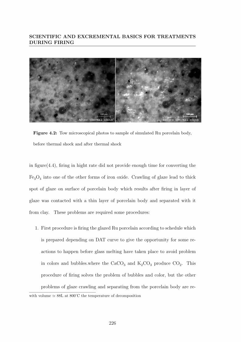
SCIENTIFIC AND EXCREMENTAL BASICS FOR TREATMENTSDURING FIRING
Figure 4.2: Tow microscopical photos to sample of simulated Ru porcelain body,
before thermal shock and after thermal shock
in figure(4.4), firing in hight rate did not provide enough time for converting the
Fe3O4 into one of the other forms of iron oxide. Crawling of glaze lead to thick
spot of glaze on surface of porcelain body which results after firing in layer of
glaze was contacted with a thin layer of porcelain body and separated with it
from clay. These problems are required some procedures:
1. First procedure is firing the glazed Ru porcelain according to schedule which
is prepared depending on DAT curve to give the opportunity for some re-
actions to happen before glass melting have taken place to avoid problem
in colors and bubbles.where the CaCO3 and K2CO3 produce CO2. This
procedure of firing solves the problem of bubbles and color, but the other
problems of glaze crawling and separating from the porcelain body are re-
with volume ' 88L at 800 C the temperature of decomposition
226

SIMULATION STUDY FOR SOME ANCIENT CERAMICS
Figure 4.3: The simulated Ru glaze recipe R47G fired at 1230 C a) normal
atmosphere b) redaction atmosphere
227

SCIENTIFIC AND EXCREMENTAL BASICS FOR TREATMENTSDURING FIRING
Figure 4.4: Apply the simulated glaze of R47G on the surface of simulated R47b
porcelain body
228

SIMULATION STUDY FOR SOME ANCIENT CERAMICS
Figure 4.5: The firing schedule to avoid bubbles appearing
mained occur as shown in figure (4.6). The firing schedule shows the relation
between temperature and time and this relation is demonstrated from fig-
ure(4.5) Some crackling is appeared and that means a very strong stress
happened between the layer of glaze and the layer of porcelain body and also
the glaze layer shrink during firing to leave portions of bare clay exposed.
2. Second procedure is a calcination for the raw materials to reduce shrink-
age coefficient of glaze , and with this applicable procedure ,an acceptable
sample of simulated Ru Guan kiln is obtained as shown in figure (4.7)and
figure(4.8)
The simulation of Ru Guan porcelain permits to practice on design clay body
and glaze from unity formula, as well as design and limitation of unity formula
229

SCIENTIFIC AND EXCREMENTAL BASICS FOR TREATMENTSDURING FIRING
Figure 4.6: Sample of Simulated Ru Guan porcelain that fired according to the
firing schedule (4.5)
Figure 4.7: Successful simulated sample (R47) of Ru Guan porcelain with crackle
treatment, according to calcined glaze recipe and firing schedule (4.5)
230

SIMULATION STUDY FOR SOME ANCIENT CERAMICS
Figure 4.8: Successful simulated sample (R47) of Ru Guan porcelain with crackle
treatment, according to calcined glaze recipe and firing schedule (4.5), with thermal
shock at 100 C
allows to design chemical and mechanical properties for both of glaze and body.
This properties is essential for using the kiln as tool for enriching ceramics forms
aesthetically by treatments during or after firing. Where in this method the
physical properties and chemical reactions of ceramic body and glaze should be
prepared to such treatment during cooling period. The simulation of Ru porcelain
body supports the technique of using thermal shock to create crackle on glazed
ceramics surfaces, where it provides the technical and scientific information for
applying porcelain body which resists thermal shock. The table (A.15) presents a
raw materials and batch recipe of porcelain body which can resist this treatment.
Also, this provides an explanation to history of Ru kiln technology, where the
231

SCIENTIFIC AND EXCREMENTAL BASICS FOR TREATMENTSDURING FIRING
lower thermal expansion coefficient of porcelain body leads to resist thermal shock
and increase the tensile stress in layer of Ru glaze which produce crackle.
4.3 Thermal shock as new technique to make
cracking
Due to the Ru Porcelain body has a property of resisting thermal shock, the
other parameter, ∆T which influences in the stress in glaze or body according to
equations(3.12) and (3.13), can be used to create cracking on glaze surfaces. This
technic is experimented by apply other recipe of glaze on Ru porcelain body and
treat this glazed porcelain by thermal shock to increase the effect of crack net on
surface of glaze. The unite formula of this glaze is :0, 29Na2O0, 15K2O0, 56CaO
. 0, 5Al2O3.
3.00SiO2
0, 43B2O3
The percentage analysis of this glaze is : 55,48 %SiO2, 15,69 %Al2O3, 5,53
%Na2O, 4,35 %K2O, 9,67 %CaO and 9,28 %B2O3. For calculating the batch
recipe for this chemical analysis , the Pemco Frit P-54 which have Equivalent
Molecular Weight 189.700 see table(A.12) is used as source of B2O3 with other
oxides. The Molecular Formula of Pemco Frit P-54 is : 0.320Na2O0.680CaO
. .
1.457SiO2
0.635B2O3
232

THERMAL SHOCK AS NEW TECHNIQUE TO MAKECRACKING
The percentage analysis of this glass is: 46.15 %SiO2, 10.44 %Na2O, 20.10 %CaO
and 23.31 %B2O3. The raw recipe of this frit (Pemco Frit P-54) is calculated
as shown in table(4.7), see appendix (A.0.8). This, batch recipe, is heated utile
melting, then it is cooled by quenching in water, and ground into a fine powder
to use in glaze recipe. The raw recipe of glaze that used to make thermal shock
treatment was presented with its calculating in table (4.8). This glaze applied on
porcelain body which simulated to sample N R47b-PGGPD of RU Guan porce-
lain body. This porcelain body is fired first fired at 1100 C and then fired with
glaze at 1150 C, where three samples are treated by thermal shock in different
degree 1100 C ,1000 C and 900 C.
233

SCIENTIFIC AND EXCREMENTAL BASICS FOR TREATMENTSDURING FIRING
Table 4.7: Calculating the percentage of raw materials for batch recipe of Pemco
Frit P-54, see appendix (A.0.8).
chemical oxides gases %
Raw materials SiO2 Na2O CaO B2O3 weight weight volume of Raw
Silicon dioxide 46.15 46.15 31.61 %SiO2
Sodium tetraborate 10.38 23.31 63.84 30.2H2O 139Lt743 C 43.74%Na2B4O7,10 H2O
Sodium carbonate 00.06 0.10 0.04CO2 0.08Lt800 C 0.08%Na2CO3
Calcium carbonate 20.10 35.87 15.8CO2 31.7Lt800 C 24,57 %CaCO3
% of oxide 46,15 10,44 20,10 23,31 100%
234

THERMAL SHOCK AS NEW TECHNIQUE TO MAKECRACKING
Tab
le4.8
:C
alcu
lati
ng
the
per
centa
geof
raw
mat
eria
lsfo
rb
atch
reci
pe
ofgl
aze
that
isu
sed
for
ther
malsh
ock
trea
tmen
t
chem
ical
oxid
esga
ses
Raw
mat
eria
lsSiO
2A
l 2O
3B
2O
3K
2O
Na 2
OC
aOw
eigh
tw
eigh
tvo
lum
e%
ofR
aw
Fri
tP
-54
18.3
79.
284.
168.
0039
.81
37.5
8%Sodiu
mca
rbon
ate
1.30
2.21
0.91
CO
21.
76Lt8
00C
02.0
9%N
a 2C
O3
Kao
lin
5.18
4.13
0.10
0.02
0,02
11.0
1.41
H2O
1.93Lt2
0C
10.3
8%A
l 2O
3·2
SiO
2·2
H2O
Cal
cium
carb
onat
e1.
622.
891.
27C
O2
2.64Lt8
00C
02.7
0%C
aCO
3
Pot
assi
um
carb
onat
e3.
955.
801.
85C
O2
4.84Lt8
00C
05.4
8%K
2C
O3
Silic
ondio
xid
eSiO
217
.43
1743
16.4
6%
Cal
cined
Kao
lin
14.4
911
.56
0.29
0.06
0.03
26.7
925
.29%
Al 2
O3·2
SiO
2
%of
oxid
e55
.48
15.6
99.
284.
355.
539.
6710
0%
235

SCIENTIFIC AND EXCREMENTAL BASICS FOR TREATMENTSDURING FIRING
Figure 4.9: Esthetic treatment of crackle, created by thermal shock at 900 C.
The esthetic treatment of crackle which is created by thermal shock shown
in: figure (4.9) first sample which treated by exiting from kiln at 900 C to room
temperature, figure (4.10) second sample which treated by exiting from kiln at
900 C to room temperature for two times with applying two layer of glaze,figure
(4.11)third sample which treated by exiting from kiln at 1000 C to room temper-
ature, figure (4.12) fourth sample which treated by exiting from kiln at 1100 C to
room temperature, and figure (4.13) fifth sample which not treated by thermal
shock, but also it has crackle where the thermal expansion coefficient of this glaze
is 49.45 × 10⁻⁷ K−1.
An image analysis is done to make a comparison between the shapes and
density of net crackle which created by thermal chock in different temperatures
236

THERMAL SHOCK AS NEW TECHNIQUE TO MAKECRACKING
Figure 4.10: Esthetic treatment of crackle, created by thermal shock at 900 C.
237

SCIENTIFIC AND EXCREMENTAL BASICS FOR TREATMENTSDURING FIRING
Figure 4.11: Esthetic treatment of crackle, created by thermal shock at 1000 C.
Figure 4.12: Esthetic treatment of crackle, created by thermal shock at 1100 C.
238

THERMAL SHOCK AS NEW TECHNIQUE TO MAKECRACKING
Figure 4.13: Esthetic treatment of crackle, created without thermal shock
at 900 C, 1000 C and at 1100 C , and which is created by difference in thermal
expansion coefficient wether between simulated Ru glaze and porcelain body or
between the same glaze which used to thermal shock treatment and porcelain
body. The net crackle density, image analysis and column chart to demonstrate
the relation between cracks number and equivalent diameter of crack in (µm) are
shown in figure (4.14). The samples presented in this figure are a sample treated
by thermal shock at 900 C, a sample treated by thermal shock at 900 C two times
with applying two layer of glaze and a sample treated by thermal shock at 1000 C,
as well as figure (4.15) presented a sample treated by thermal shock at 1100 C, a
sample not treated by thermal shock and sample of simulated Ru Guan porcelain
239

SCIENTIFIC AND EXCREMENTAL BASICS FOR TREATMENTSDURING FIRING
R47. The image analysis shows that the result of use thermal shock is significant
effect in the size and density of cracks on surface of glaze, where the thermal shock
at 900 C high density of crackle from all samples and it has the smaller size of
equivalent circle diameter. As well as the thermal shock at 1000 C and 1100 C
increase the effect of cracks on surface glaze where thermal shock in different
temperature leads to different in density and size of cracks. Also, the significant
effect of glaze structure and porcelain body properties refer to the important
of calculating and design glaze and porcelain structures to improve the esthetic
crackle pattern by using the thermal shock during firing which required design a
tool like a jet to treat the forms by thermal shock during firing. In addition to the
significant effect of thermal shock in the size and density of cracks on surface of
glaze, there is other benefit for this technique, where thermal shock creates cracks
on surface of glaze when glazes are in soft state, there fore cracks are created on
surface layer of glaze which is affected by cooled air but the deeper layers still
soft to fill in the cracking net which is an advanced to create crackle feature
without continuing the depth of cracking to porcelain body this observation is
shown under microscope in figure (4.16).
240

THERMAL SHOCK AS NEW TECHNIQUE TO MAKECRACKING
Figure 4.14: The net crackle density , image analysis and column chart for
samples treated by thermal shock at 900 C ,at 900 C two times with applying two
layer of glaze and at 1000 C
241

SCIENTIFIC AND EXCREMENTAL BASICS FOR TREATMENTSDURING FIRING
Figure 4.15: The net crackle density , image analysis and column chart for
samples treated by thermal shock at 1100 C , sample not treated by thermal shock
and sample simulated to R74
242

THERMAL SHOCK AS NEW TECHNIQUE TO MAKECRACKING
Figure 4.16: Typical optical surface morphology of surface crackle glaze is created
by thermal at 900 C, shows the filling of the deep of crack
243

SCIENTIFIC AND EXCREMENTAL BASICS FOR TREATMENTSDURING FIRING
4.4 Crack pattern on ceramics surfaces by mod-
ification of kiln structure.
From history of crackling technique and from scientific and experimental study, it
became clear that thermal expansion of glaze during firing process, as well as sud-
den change in temperature, are significant factors in producing crackle treatment
on ceramic surface. Therefore the structure of kiln could help in reproduction
of that technique and modify it in new design by using new technology. These
will be useful to ceramic designer and artists. Especially we can use the variation
of linear thermal expansion of the various forms of silica (quartz, cristobalite,
tridymite, vitreous silica) [150]. As well as all the forms of silica show high coeffi-
cient comparative to vitreous silica which has the lowest linear expansion, about
0.05% between 20 and 1000 C (figure 4.17), and on this account it withstands
sudden changes of temperature without shattering [150], but the quartz, cristo-
balite and tridymite not withstand sudden changes of temperature. Therefore
this information permits to use thermal shock for producing esthetic crackle from
different density of cracking, or from contrast between cracking and not cracking
on surface of once ceramic form. This esthetic depends on design thermal expan-
sion of glaze which is compatible with thermal expansion of porcelain body, and
use different forms of silica, vitreous silica who doesn’t give cracking and quartz
who give cracks. The Seger formula for these recipes is same but the type forme
244

CRACK PATTERN ON CERAMICS SURFACES BYMODIFICATION OF KILN STRUCTURE.
Figure 4.17: Thermal expansion of the principal forms of silica
of silica is different. So there is two factors is requred in production of cracks on
glazed surfers, first one is calculating thermal expansion coefficient of glaze by
design its chemical composition, second one is design tool to make sudden change
in temperature, thermal shock.
The sudden change in temperature during glaze firing inside the kiln is aimed.
It can be done by modification of kiln design, for sending cold air inside the kiln
from unit filled with compress air, the temperature of which can be cold as 0
C. That cold air is send to kiln through long tube which is isolated to keep air
isolated from room temperature, and it will be in contact with kiln from the
ceiling by large jet, as shown in(4.18). This jet is designed to take an especial
shape as shown in figure figure(4.19).
245

SCIENTIFIC AND EXCREMENTAL BASICS FOR TREATMENTSDURING FIRING
Fig
ure
4.1
8:
Illu
stra
tion
for
com
pre
ssin
gco
ldai
rin
teri
or
kil
n
246
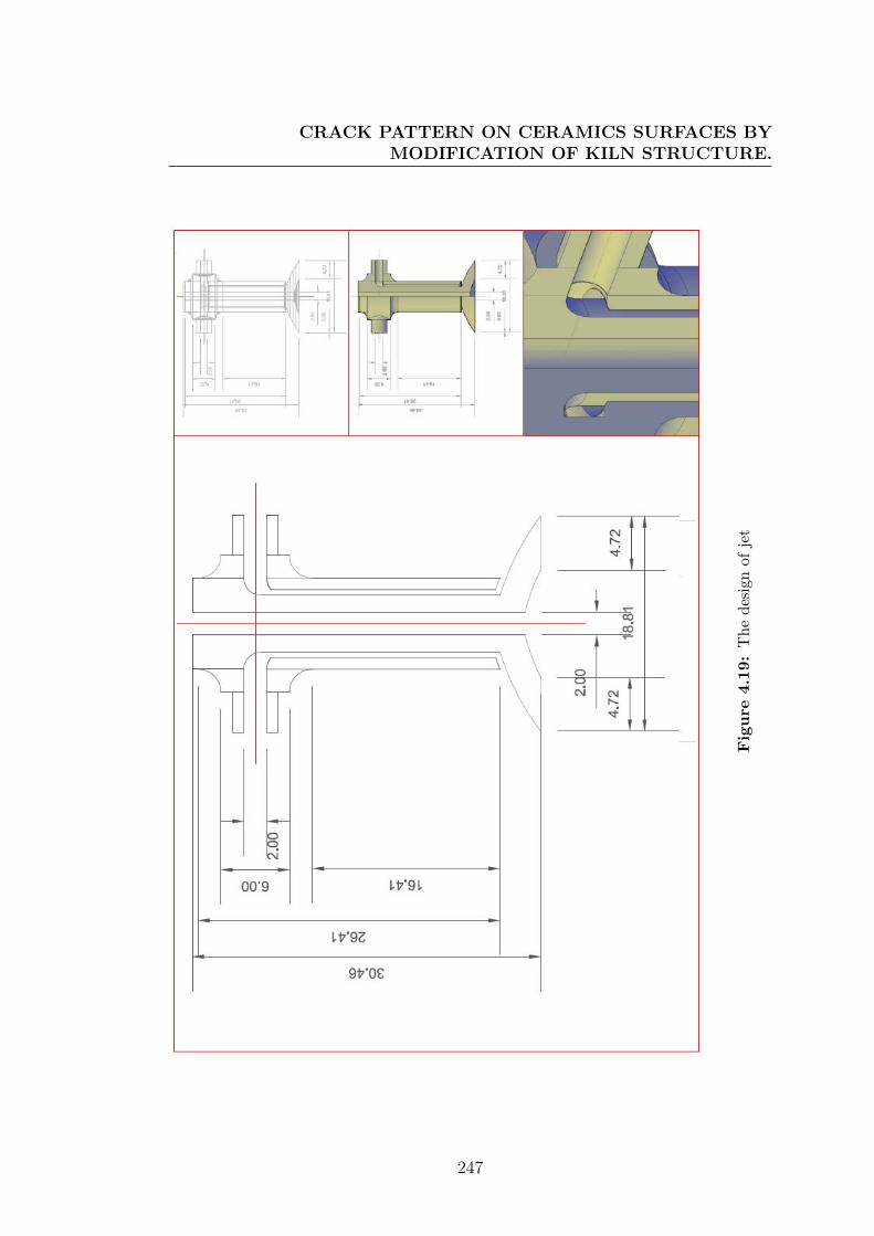
CRACK PATTERN ON CERAMICS SURFACES BYMODIFICATION OF KILN STRUCTURE.
Fig
ure
4.1
9:
Th
ed
esig
nof
jet
247

SCIENTIFIC AND EXCREMENTAL BASICS FOR TREATMENTSDURING FIRING
Coanda phenomena leads to design the part of jet which is fixed inside the
kiln as carved surface to distribute the air. The influx of cold air follows a
convex surface of jet, rather than a straight line in its original direction, the
figure (4.20) shows a staying of fluid attached to convex surface according to
Coanda phenomena[151]. The cold air is injected inside the kiln with particular
speed to touch surface of ceramic forms until the temperature of air fluid is still
lowest than the temperature of ceramics surface, see figure (4.22).
When injected cold air take its path to go inside the kiln through the tube, its
temperature will rise gradually. When it will pass through several hot degrees in
the tube, because the heat can be transferred from inside the kiln by convection.
The mass of cold air when get out from the jet inside kiln, it is arrived to last point
where cold air can be heated by contact with jet part inside the kiln so the air
temperature is raised again by radiation and conduction and then it will fluid into
atmosphere of kiln with this temperature lower than temperature inside the kiln.
Therefore a cold front will be formed, as shown in figure (4.21). The temperature
of cold front will make sudden changing in temperature which increases the tensile
stress in surface of glaze to give cracks. As well as the mass of cold air which
start from compressed unit with temperature T1, it will be raised to T2 at the
end of tube, then the temperature will be raised to T3 when it get out from the
jets and the cold front will arrive to touch surface of ceramics with Tn. The heat
248

CRACK PATTERN ON CERAMICS SURFACES BYMODIFICATION OF KILN STRUCTURE.
Figure 4.20: Illustration of staying of fluid attached to convex surface according
to Coanda phenomena
249

SCIENTIFIC AND EXCREMENTAL BASICS FOR TREATMENTSDURING FIRING
Figure 4.21: Illustration for cold front, the contact between cold mass of air and
warm mass of air
250

CRACK PATTERN ON CERAMICS SURFACES BYMODIFICATION OF KILN STRUCTURE.
conduction is defined by following equation:4.2:
Q
t= K × A× ∆T
d(4.2)
where Q is heat conduction, t is time, k is a thermal conductivity,A is area, ∆ T is
difference in temperature and d is thickness. Due to the Ka thermal conductivity
of air is 0.025 W/(m.K), while Kg thermal conductivity of glasses (glaze: ceramics
surface) is 1.1 W/(m.K), the temperature of atmosphere inside kiln will be equal
to the temperature of ceramics forms, and with injected cold air into kiln in such
speed from jet which is designed to affect in thickens and shape of air, the air will
arrive to ceramics surfaces with temperature less than their temperature. So the
ceramic surface will be effected by cold front more than the mass of cold air in
contact with the hot atmosphere of kiln. When the mass of cold air meet a mass
of hot air, it will be created a cold front which is shown in figure (4.21). This cold
front take the cold air to the bottom of the kiln and warm air will go to the top
of the kiln so design of jet has a center tiny hole to let warm air free to get out
during cracking treatment. The cold front keeps partly the temperature of mass
of cold air less than the ceramic forms surface when it touch them to make stress.
This stress creates cracks in glaze layer. The curved surface of jet and curved
surface of ceramics forms helps to distribute cold air in atmosphere of kiln, and
will touch all forms inside the kiln to get the cracks, as shown in figure (4.22).
This treatment is done when temperature of ceramic forms slow down from
251

SCIENTIFIC AND EXCREMENTAL BASICS FOR TREATMENTSDURING FIRING
Figure 4.22: Illustration of thermal chock treatment interior kiln
matured temperature to room temperature after that glaze firing is completed.
The linear thermal expansion helps to determine when cold air is inserted inside
the kiln. Varieties of cracks which is produced by experimental treating will be
produced by thermal shock inside kiln. In other words, using quartz, cristobalite
or tridymite in glaze structure will give cracks when it was treated by inserting
cold air into atmosphere of kiln, for some time, but using vitreous silica in glaze
structure will not give cracks in the same firing treatment under the same condi-
tions. So, with design glaze composition and with improved kiln design, esthetic
252
CHEMICAL TREATMENT FOR PRODUCING COPPER ORESAS GLAZE COLORANT
treatment is obtained as a technique for producing pattern of cracking in part
area and not cracking in other part area in same form.
4.5 Chemical treatment for producing copper
ores as glaze colorant
This treatment is related to use chemical reactions or their conditions as method
to enrich esthetic of glaze by irisation. The reduction atmosphere and temper-
ature are used with iron oxides in Chinese glazes to produce many glaze colors,
and they are used also in Iraq to produce many glaze luster and metallic colors.
The reaction between carbon gases in atmosphere of kiln and colorant in glaze
structure was a common treatment during firing, the effect of this treatment was
mentioned in chapter (3) at sections (3.7.1.1) and (3.7.1.2). The influence of this
reaction on the esthetic of glaze colors promotes to think about a possibility of
improving this technique. Ores of copper have various and esthetic colors which
are looked forward to apply in particular glaze. This technique depends on three
factors: the first is a glaze structure, the second is an atmosphere which permits
to produce ores of copper in glaze as a thin film, and the third is kiln technology
which allows to do chemical treatment at time on firing schedule. Duration of this
treatment is determined by realization of the balance between the temperature
which is required for chemical reaction and the influence of this reaction on glazes
253

SCIENTIFIC AND EXCREMENTAL BASICS FOR TREATMENTSDURING FIRING
quality and esthetics. The phase diagram of chemical reaction system gives the
temperature of reactions and the components necessary and sufficient to create
phases of copper ores as nanocrystal colorant in glaze. Ellingham diagram is used
to expect the influence of these reactions on glaze and on its chemical ingredients.
4.5.1 Sulfide, copper ores
The sulfide iron copper ores (FexCuySz) is an example of these nanocrystal col-
orant which can be created on surface of glaze by chemical treatment during firing
from two reactions, the first is reducing copper oxide and iron oxide to copper
ions and iron ions, the second is the reaction between sulfur vapors and copper
ions and iron ions. This permits to decorate glaze with very nice colors, where
the color of ores which are produced by this technique describe as following:
• Bornite is a copper iron sulfide mineral with chemical formula Cu5FeS4. It
has a brown to copper-red color on fresh surfaces that tarnishes to various
iridescent shades of blue to purple in places. Its striking iridescence gives
it the nickname peacock copper or peacock ore [152].
• Chalcopyrite is a copper iron sulfide mineral. It has the chemical formula
CuFeS2. It has a brassy to golden yellow color.
• Covellite or covelline is copper sulfide mineral with the formula CuS. It has
indigo blue color.
254

CHEMICAL TREATMENT FOR PRODUCING COPPER ORESAS GLAZE COLORANT
• Pyrite, or iron pyrite, is an iron sulfide with the formula FeS2. it has metallic
luster and not bright brass-yellow hue, so it earned the nickname fool’s gold
because of its look like gold.
• Cubanite is a yellow mineral of copper, iron, and sulfur, with chemical
formula CuFe2S3.
• Chalcocite is a copper(I) sulfide Cu2S, is opaque, being colored dark-gray
to black with a metallic luster.
4.5.2 Phase diagram of copper-iron-sulfur system
Fore producing nice colors of copper iron sulfur ores which are described above,
The phase diagram of copper-iron-sulfur system demonstrates the ratios between
elements of Cu, Fe and S which is necessary and sufficient to produce each phase of
this ores. Also, a particular temperature which is necessary to form each phase is
mentioned in same phase diagram, as shown in figure(4.23). The bornite Cu5FeS4
which has peacock color,is merged from right Cu:Fe:S ratio (5 : 1 : 4) as it is
confirmed from chemical formula at 700 C under constant sulfur vapor pressure
of 455 mm Hg (60661.51 Pa). Under the same constant of sulfur vapor pressure
with variation in Cu:Fe:S and at different temperature other forms of copper iron
sulfur ores will be merged. Chalcopyrite merges with respect to that the Cu:Fe:S
ratio is (1:1:2),and it forms at 557 C. Cubanite merges with right Cu : Fe : S
255

SCIENTIFIC AND EXCREMENTAL BASICS FOR TREATMENTSDURING FIRING
Figure 4.23: Cu−Fe−S system under constant sulfur vapor pressure of 455 mm
Hg (60661.51 Pa)[20].
ratio (1 : 2 : 3) at 675 C [20, 153, 154]. The Cu-S system demonstrates that
Chalcocite Cu2S is formed at 1130 C when Cu/S ratio is 2,see figure (4.24). The
Covellite is formed at 507 C when Cu/S ratio is 1. The Fe-S system refers to the
temperature and ratio of iron Fe to sulfur S for forming Pyrite FeS2 which look
like gold at 743 C with Fe/S ratio equal to 0.5, and pyrrhatite FeS is formed
at 988 C with Fe/S ratio equal to 1, as phase diagram Fe-S system shows in
figure(4.25)[20, 153, 154]. The pyrrhatite color is similar to pyrite. So the
256

CHEMICAL TREATMENT FOR PRODUCING COPPER ORESAS GLAZE COLORANT
Figure 4.24: System Cu−S [20].
257

SCIENTIFIC AND EXCREMENTAL BASICS FOR TREATMENTSDURING FIRING
Figure 4.25: System Fe−S[20].
258

CHEMICAL TREATMENT FOR PRODUCING COPPER ORESAS GLAZE COLORANT
phase diagrams of Cu-S ,Fe-S and Cu-Fe-S refers to that the merged phase of
copper iron sulfur ore is based on contents of iron copper and sulfur, and based
on which temperature and pressure the vapor of sulfur react with copper and
iron ions. Therefore these parameter which are related to be treatments during
firing to create different nice colors included gold color, metallic reflation colors
and peacock color.
Copper and iron ions were used as colorant in glaze of two historical ceramics
types which are studied historically and scientifically in this thesis. There tech-
niques based on reaction atmosphere during firing for transferring oxides phases
of iron and copper to ions or metallic state.
The states of iron and copper are determined according to the degree of re-
duction. This is the first treatment which can be followed by another treatment
which is sulfur vapor to form copper iron sulfur ores. Nanocrystals of these ores
are colorant for glaze. The Cu2+ ions was obtained in a glass network by reduction
treatment.
2CuO + C−→2Cu(II) + CO2
The Fe2+and Fe3+ ions were obtained in a glass network by reduction treatment.
Fe3O4 + 2C−→Fe(II) + 2Fe(III) + 2CO2
Therefore the Cu2+,Fe2+and Fe3+ can be obtained in frits treatment, redaction
259
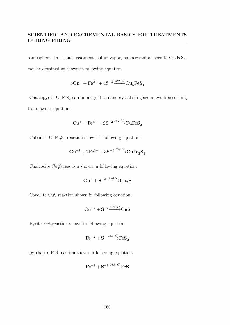
SCIENTIFIC AND EXCREMENTAL BASICS FOR TREATMENTSDURING FIRING
atmosphere. In second treatment, sulfur vapor, nanocrystal of bornite Cu5FeS4,
can be obtained as shown in following equation:
5Cu+ + Fe3+ + 4S−2700 C−−−→Cu5FeS4
Chalcopyrite CuFeS2 can be merged as nanocrystals in glaze network according
to following equation:
Cu+ + Fe3+ + 2S−2557 C−−−→CuFeS2
Cubanite CuFe2S3 reaction shown in following equation:
Cu+2 + 2Fe2+ + 3S−2675 C−−−→CuFe2S3
Chalcocite Cu2S reaction shown in following equation:
Cu+ + S−21130 C−−−−→Cu2S
Covellite CuS reaction shown in following equation:
Cu+2 + S−2507 C−−−→CuS
Pyrite FeS2reaction shown in following equation:
Fe+2 + S−743 C−−−→FeS2
pyrrhatite FeS reaction shown in following equation:
Fe+2 + S−2988 C−−−→FeS
260

CHEMICAL TREATMENT FOR PRODUCING COPPER ORESAS GLAZE COLORANT
4.5.3 Design glaze formula for chemical treatment by sul-
fur vapor
Copper iron sulfur ores have to be nanocrystals colorants to give to glazes there
colors. These nanocrystals have to imped inside the glaze layers, and this required
that glaze should be in soft state when nanocrystals are formed. The exchange ion
mechanism between alkaline ions leads coloring crystals to diffuse inside the glaze.
Therefore the continents of alkali oxides in glaze is factor which influences in
treatment results. In addition to refractive index of glaze which can be calculated
from composition chemical oxides of glaze. The lead oxide PbO and B2O3 have
important role in value of refractive index of glaze, see section(3.7.1.1). Therefore
formula of glaze is limited by calculating the temperature of heat treatment of
glaze, permitting colorant to diffuse and imped in side glaze. Temperature of
heat treatment is calculated by flux factor and temperature of heat treatment
equations (3.3 and 3.4). This makes relation between the temperature viscosity
of glaze, heat treatment of glaze and the temperature of forming copper iron
sulfur ores. The additive of lead oxide can be calculated from equation(3.7), and
the additive of boron trioxide B2O3 can be calculated according to it is effect
in thermal expansion coefficient (TEC) of glaze, due to the relation between its
percentage in glaze and (TEC) of glaze. Containment of Na+ and K+ in glaze is
determined by that they are considered the driving force responsible for diffusion
261

SCIENTIFIC AND EXCREMENTAL BASICS FOR TREATMENTSDURING FIRING
of silver and copper ions into glaze layer diffusion. Therefore this treatment, as
method to produce esthetic metallic colors on glaze surfaces, required that Seger
formula glaze contains Na2O, K2O and PbO as glass network modifier, Al2O3 as
intermediate former and SiO2 and B2O3 as glass network former. So the basic
Seger formula of this glaze as flowing:
K2ONa2OPbO
. Al2O3.
SiO2
B2O3
+ Fe3O4
CuO
It is likely to some modifiers added to formula according to calculate all of
flux factor (F) , TEC, refractive index, additive of lead oxide and elasticity of
glaze. Also, these calculations determine the limit formulas.
4.5.4 Thermodynamic driving force for chemical reaction
in these treatments
In this chemical treatment, copper iron sulfur ores are intended as crystal col-
orants which merge from chemicals reaction between the Fe+2,+3and Cu+,+2 ions
in glaze structure and S–,–2ions from atmosphere of kiln. This treatment can be
considered as chemical shock to glaze oxides, especially these chemical reaction
are in driving seat to react with Fe2O3 and CuO instead of others chemical in-
gredients of glaze. The Ellingham Diagram represent the thermodynamic driving
262

CHEMICAL TREATMENT FOR PRODUCING COPPER ORESAS GLAZE COLORANT
force for a particular reaction to occur related to such temperature and pres-
sure, and it relied on the change in free energy ∆G as an indicator to chemical
reactions. The free energy can be presented in following equation:
G = G◦ +RT ln
(p
p◦
)(4.3)
where G is free enthalpy ,R is ideal gas constant, G◦ is defined to be the standard
free enthalpy at the standard pressure, p◦. The difference in free enthalpy be-
tween the products of the chemical reaction and the reactants is the free enthalpy
change, ∆ G . There will be a driving force for the reaction to occur if the free
enthalpy of the products is less than the free enthalpy of the reactants . The free
enthalpy change can be calculated in standard states by following equation:
∆G = ∆G◦ +RT ln
(pproduct
preactantApreactantB
)(4.4)
where the pproduct is a product pressure, preactantA is a reactant A pressure and
preactantB is a reactant B pressure The negative value of free enthalpy change ∆
G means that reaction will occur and the reaction will continue if ∆ G remains
negative until a point of equilibrium, the free enthalpy change∆G for the reaction
is equal to zero. Therefore the ∆G◦ can be calculated by following equation:
∆G◦ = −RT ln
(pproduct
preactantApreactantB
)= −RT lnKp (4.5)
whereKP is the equilibrium constant for the reaction at constant pressure. The
standard free enthalpy change, ∆G◦ refers to a link between the thermodynamics
263

SCIENTIFIC AND EXCREMENTAL BASICS FOR TREATMENTSDURING FIRING
of a reaction and its chemistry. The Ellingham Diagram present the relation be-
tween the ∆G◦ which indicate to driving force for reactions, and temperature for
oxidation and sulphidation reactions for a series of metals as shown in figure(4.26).
This diagram demonstrate the value of ∆G◦ for chemical reactions between series
of metals and oxygen or sulfur as function of temperature in particular pressure.
This value mentioned to driving force for a oxidation and sulphidation reactions
to occur when ∆G◦ value is negative and the priority of reaction can be inferred
by the comparison between the value of ∆G◦ for each reaction as shown in graph
of Ellingham Diagram. The reactions which are represented in inferior position in
diagram has a priority to occur before reactions which are represented in superior
position in diagram [30]. So this diagram permits to compere between relative
stabilities of different ingredient glazes oxides when they are heated in carbon or
sulfur atmosphere. The ∆ G◦ value of reaction between carbon and oxygen to
produce CO2 in such temperature is record point in such temperature and record
line as a function of temperature. This line divides the diagram to two parts
of reactions the reaction in top parts is lower than low part in driving force to
react with oxygen. Therefore carbon is show more driving force to react withe
free oxygen in atmosphere of kiln and then to react with atomics oxygen from
element oxides. This means that the glaze oxides which are influenced by carbon
treatment are oxides of elements of which reaction with carbon is represented by
line above the line of reaction between carbon and oxygen in Ellingham Diagram.
264

CHEMICAL TREATMENT FOR PRODUCING COPPER ORESAS GLAZE COLORANT
Figure 4.26: Ellingham diagram for the free energy change of formation of metal-
lic oxides [30].
265

SCIENTIFIC AND EXCREMENTAL BASICS FOR TREATMENTSDURING FIRING
This also is used to defined wide range of reactions. This comparison for carbon
treatment can be demonstrated from figure (A.1) where the free enthalpy change
values ∆G of iron oxides forms are started to be upper the values of carbon oxides
after 999 K in standard state. Therefore the reduction for iron oxide is above
999 K temperature. As well as figure (A.2) shows the wide range of reduction
of copper oxides by carbon. the colorant oxides, Fe2O3 and CuO, are affected
by the carbon reaction. The influence of carbon reaction can be inferred also by
the Ellingham Diagram, where the free enthalpy change values ∆G of potassium
oxides and sodium oxides forms are under the values of carbon oxides that not
include Na2O, where the the form Na2O is affected be carbon above 1400 K as
shown in figure (A.4). The SiO2 and B2O3 is not affected by carbon redaction as
shown in figure(A.5). Therefore the Seger formula of glaze after carbon redaction
treatment or hydrogen will be changed to the following formula:
K2ONa2OPbO
. Al2O3.
SiO2
B2O3
+ Fe+3
Cu+
Due to the priority of sulphidation is to react with Fe and Cu , this glaze
formula is ready to treat by sulphidation reactions for producing copper iron
sulfur ores as colorant, and kind of ore gives its color to glaze and the formula
after firing will be as following for peacock color:
266

CONCLUSION
K2ONa2OPbO
. Al2O3.
SiO2
B2O3
+
Cu5FeS4
The possibility of improving treatments during firing can be achieved by
preparation to the glaze composition and by the possibility of expecting the effect
of such designed treatment during or post firing. The method which is used to
produce copper iron sulfur ores can be used to proper another ores or to defined
such reactions which lead to especial esthetic treatment on glaze surfaces.
4.6 Conclusion
Using atmosphere of kiln and conditions of firing as treatments to affect in glazes
colors and textures were established from determining the factors which effect on
crackle and which effect in reflecting metallic colors. The liner thermal expansion
coefficient (K−1), the temperature change (∆T ) and thickens of glaze layer are
the effective factors in the shape of crackle and its density in surface of glaze.
the liner expansion coefficient of glaze and clay body are related to the chemical
composition of them. The temperature change is related to conditions of firing
process and the thickens of glaze layer is related to apply glaze on body. These
three factors combined pelmet to control the net of crackle. Therefore the kiln
267

SCIENTIFIC AND EXCREMENTAL BASICS FOR TREATMENTSDURING FIRING
structure can be considered a tool to allow thermal shock, the treatment during
firing to produce crackle on surface ceramics. the simulation of Ru kiln glaze and
porcelain body confirm that the crackle on Ru Guan ceramics is attributed to
the low thermal expansion of porcelain body.
The phase state of colorant in glaze and the nature of glaze are the factors
which affect in color of glaze. Chemical reaction between the colorant oxides and
the atmosphere of kin determines this state of colorant. The iron ions in Chines
glazes play important role in determination the color and the hue of color, where
the ratio between Fe+2and Fe+3 which related to oxygen probe atmosphere of
kiln reading. as well as the the relative concentration of Cu/(Cu+Ag) and Ag
/(Cu+Ag) ratio determine the luster color and the metallic state of Cu and Ag
led to diffusion light withe especial esthetic treatment. the chemical reaction for
colorants is related to chemical treatment which is related to kiln design and
technology. Design glazes as an in put of thermodynamic reaction depends on
chemical formula which can be converted to weight fraction and to raw materials.
This is one of practical application for the science in ceramic art. This also was
used in this thesis to simulate ancient ceramics and for design glazes which is the
most appropriate for thermal shock treatment, reduction atmosphere treatment
as historical treatment, and sulphidation atmosphere treatment as a development
for treatments which are made during firing process. The calculations neces-
sary for limit formula and ratios between glass former ,intermediate former and
268

CONCLUSION
modifier former or between RO and R2O permeated to relate between esthetic
treatment of glaze and its chemicals components. This relation leads to define
the conditions that can be affect in chemical and physical proprieties which are
closely related to esthetic of glazes and their colors. Also, the process of deter-
mination, which oxides of glaze components are stable and which one is effected
during the treatment, was based on the free energy change of chemical reaction
as function of temperature for each oxide. Therefore the relation between science,
technology and art is demonstrated in this technique of doing treatment during
firing. As well as, the history of technologies helps in limiting scientific study to
glaze and/or porcelain body of Ru kiln and metallic reflection.
Therefore the kiln which permits to this treatments - thermal shock , redaction
atmosphere or sulphidation atmosphere- is required to do this treatments.
269


Chapter 5
Design kiln for thermal shock
and chemical treatments
This chapter aims illustrating the functional analysis and designing conception
of new kiln which is attempted to apply the historical treatments during
firing and its devolvements. In general rather than in particular, the architecture
of an intermittent kiln reformulated in case of additive one of either functions
for producing crackle and metallic reflation color on surface of glazed ceramics.
Within the framework of functional, the results of historical and experimental
studies are represented in part of requirements, expected services, and solutions.
The APTE∗ method is used to explain the plan of new kiln. Mathematical study
∗APTE is application des techniques d’entreprises, a method of functional analysis and
value analysis for the project management of innovation and optimization.
271

DESIGN KILN FOR THERMAL SHOCK AND CHEMICALTREATMENTS
is used to estimate energy which is required for operating the kiln, and choice
refractory materials for building kiln. A finite element programme( ANSYS) is
used to evaluate the deformation in kiln structure .
5.1 Introduction
The last main step in the manufacture of ceramic forms is the firing process that
gives them solidity. In this step, the ceramic forms are treated by heat to obtain
the temperatures between 900 C, in case of earthenware, and 1300 C in case of
stoneware and porcelain, according to the results of historical and experimental
studies, this process is necessary for enriching glaze esthetics treatments. Dur-
ing firing, the ceramics forms are treated by some of the chemical and physical
changes, which clearly influence in their aesthetic. Therefore, the aims of the
firing process is not only for providing forms to sufficient solidity, but also it is
used to give them an aesthetic property.
Brongniart [56] hinted to this when he said
”Le but essentiel de la cuisson de poteries est leur donner assez de solidite pour
qu’on puisse les manier sans les briser et assez de densite pour les rendre plus
ou moins impermeables aux liquides. On s’est propose ensuite de leur donner
plus d’eclat, d’aviver certaines, et on a ete jusqu’a vouloir donner a la pate une
translucidite flatteuse.”
272

INTRODUCTION
During the evolution of ceramic kilns, there atmosphere were exchanged from
reducing to oxidizing atmosphere, due to chemical reactions between the glaze
and vapor and gases in atmosphere during heat treatment, where some techniques
of decorate glaze produced as are depended on change atmosphere of kiln to
impact on color and texture of ceramics surfaces,refer to(1.7, and 2.3) section.
These techniques did not continued in history of ceramics, due to difficulties of
firing technologies in modern kiln. Despite these difficulties some potters try
to emulate these techniques for producing traditional ceramics or using there
esthetics treatment, they are still, far from apply them in industry of ceramic. To
use these techniques without contamination of the environment, our goal design
and produce kiln providing such treatment during or after firing.
From historical study and scientific study, we find that the aesthetic of glazed
ceramic forms can be enriched by texture and color treatments which are produced
by changes in condition of firing process. There are two changes which are taken
in account to design new kiln. First a slow down in temperatures inside the
kiln during cooling period of glaze firing, accordingly, an area of crackle will be
created to use as decoration on glazed ceramics forms. Second one is chemical
treatment which is applied by changing atmosphere of kiln in one firing process
from normal condition to reduction or/and sulphidation conduction, so that, the
chemical reactions will exist in glaze structure to change the state of colorants
ions to give glaze a metallic sheen color.
273

DESIGN KILN FOR THERMAL SHOCK AND CHEMICALTREATMENTS
The traditional techniques are developed in new application to glaze structure
and treatments during firing, where metallic reflation of the copper plus iron ions
which are used in two historical techniques, are prepared in one batch recipe of
glaze to treat by carbon, vapor of H2O and sulfur. This treatments lead to create
nice different colore of iron and copper sulfur ores. Therefore, the especial kiln
which allow these treatments in applicable procedures. Therefore determination
of requirements, which are necessary in ceramic kiln who can be used as a tool
for enriching esthetic treatments of glazed ceramics, are presented as following:
1. Ability to achieve 1300 C or less for firing many types of ceramics from
terracotta to pericline.
2. The architecture of this kiln should has the following procedures:
(a) Keep the condition of firing process in state of neutral atmosphere
during heating process from 20 to 1300 C which is the temperature of
glaze maturing.
(b) Change the condition of firing process from natural to reduction at-
mosphere during cooling process from 1300 to 20 C.
(c) Allow to insert a few materials inside the kiln which change its atmo-
sphere at appropriate temperature.
(d) Allow to inject cold air inside the kiln for treating glazed forms by
thermal shock.
274

PRESENTATION OF NEW KILN
(e) Distribute gases and smoke which interact with ceramics surfaces in-
side the kiln.
(f) Close the kiln tightly during the firing to prevent gases and smoke
from leaking into outside air.
3. Chemical treatment of sulfur oxide and carbon dioxide that come out of
kiln.
In order to include all this requirements in design of new kiln, the functional
analysis and the APTE method are used to explain the system and optimize
performances.
5.2 presentation of new kiln
This kiln allows doing chemical treatments and thermal shock treatment during
firing. It was designed to resemble an firing condition controller in order to apply
metallic reflection colors and crackle on surface of glazes which will be designed
as mentioned in section(4.5.3). The user actuates the control conditions of firing
according to chemical operations and their results, the Ellingham diagram and
phase diagrams of metals guide to determine the accurate time for changing the
conditions on firing schedule.
275

DESIGN KILN FOR THERMAL SHOCK AND CHEMICALTREATMENTS
Figure 5.1: The new kiln for thermal shock and chemical treatments when it is
closed
276

PRESENTATION OF NEW KILN
Figure 5.2: The new kiln for thermal shock and chemical treatments when it is
open
277

DESIGN KILN FOR THERMAL SHOCK AND CHEMICALTREATMENTS
5.3 Functional analysis for new kiln
5.3.1 Study boundaries
A limited study of this kiln consists of firing chamber, the heating element, re-
fractory walls, tools for measuring temperature, tools for changing condition of
firing from natural to redaction, unite for treating gases which come out of kiln,
and adapt the method of closing the kiln. Kiln is connected to power supply of
electricity and control panel.
5.3.2 Articulate the requirements
This kiln allows to treat the glazed ceramics surfaces during firing by some gases
and vapors which can interact chemically with some components of glaze, and
produces the expected aesthetic appearance. It also allows to treat glazed ceram-
ics surfaces by thermal shock during firing to produce a net of cracks on surface
of glaze.
5.3.3 Utilization phase of new kiln
This kiln is used to produce glazed ceramics that can be decorated by metallic
reflection, peacock color, indigo blue color, dark-gray to black with a metallic
luster and golden yellow colors, or that can be decorated by crackle. Also, it can
be used to produce the five grate famous kilns from history of Chinese ceramics,
278

FUNCTIONAL ANALYSIS FOR NEW KILN
as well as metallic luster from history of islamic ceramics, refer to (2.3.2.3, 2.3.2.4,
4.5, and 4.4).
5.3.4 Octopus diagram of new kiln
This diagram is used to analyze the complex system of new kiln and its envi-
ronment, where it demonstrate elements of external milieu (elements du mileu
exteroeur-EME ), and their relations with new kiln. In this diagram, the system
is organized into the new kiln and external elements which are deal with this kiln.
The various relations between every functions of kiln can be defined into serves
function(FS), principle function (FP), or/and constraint function (FC). As shown
in figure(5.3), the elements of external environment are glazes, metallic reflection
color, crackle, forms, environment, insulation standard, heating standard, control
atmosphere, and construction. The principle function:
(FP1) firing biscuit and glaze.
The serves functions:
(FS1) produce glaze which is decorated by metallic luster colors.
(FS2) produce glaze which is decorated by crackle.
(FS3) change the conditione of firing process.
The constraint function:
(FC1) respect the chemical reactions conditions and physical properties.
279

DESIGN KILN FOR THERMAL SHOCK AND CHEMICALTREATMENTS
Figure 5.3: Octopus diagram defining the serves function, principal functions and
constraints in the environment of new kiln
(FC2) adapt to the environment.
(FC3) design construction of kiln which allows FS1, FS2 and FS3.
(FC4) respect the standards of thermal insulation.
(FC5) respect properties of refractory which are selected for building the contrac-
tion of kiln.
(FC6) respect the standards of heating.
According to this diagram, design the kiln is studded to highlight and show pro-
duction of new kiln.
280

FUNCTIONAL ANALYSIS FOR NEW KILN
5.3.5 Characterization of elements of external milieu(EME)
Elements of external milieu EME are limited into some qualifications, there cri-
terions, there levels, and/or there flexibilities, as following:
5.3.5.1 Unfired forms
The qualification of unfired forms is volume, maximum width or diameters of
cross section of form is 360 mm. The maximum high of form is 530 mm.
5.3.5.2 Fired Forms
The qualification of fired forms is temperature of firing , maximum temperature
is 1350 C, and 950 C is acceptable for earthenware.
5.3.5.3 Glaze
The qualification of glaze are Seger formula[127] of glaze and colorant oxides. In
Seger formula, components oxides are classified into glass formers or acids SiO2,
RO2, and R2O5 which are criticized by parties molecular in number 3 molecule
minimum 6 molecule maximum, intermediate formers Al2O3, and R2O3 which are
criticized by parties molecular in number 0.3 molecule minimum 0.55 molecule
maximum and modifier former ROand R2O which are criticized by parties molec-
ular in number, where the sum of all percentages equal 1. The colorant oxides are
classified into iron oxides which criticized by parties molecular in number 0.005
281

DESIGN KILN FOR THERMAL SHOCK AND CHEMICALTREATMENTS
molecule minimum 0.2 molecule maximum, and copper oxides which criticized by
parties molecular in number 0.1 molecule minimum 2 molecule maximum.
5.3.5.4 Control atmosphere
The qualifications of atmosphere of firing are classified by carbonic, sulfuric at-
mosphere and vapor of water. The rosin∗ is used as organic materiel for produce
carbonic atmosphere where its practical melting point varies from 100 C to 120
C. The sulfur is used to produce sulfuric atmosphere, where its practical melting
point is 115 C. Water is used to produce vapor.
5.3.5.5 Crackle
The qualifications of crackle are shape and number of crackle on area, where it is
criticized by number and length of equivalent diameter on unite of surface.
5.3.5.6 Metallic reflections colore
The qualification of metallic reflections is colore which is by λ wavelength in µm.
∗Rosin, colophony or Greek pitch is a solid form of resin obtained from some plants and
composed of abietic acid C19H29 · COOH, mostly pines and conifers, produced by heating fresh
liquid resin to vaporize the volatile liquid terpene components [155].
282

FUNCTIONAL ANALYSIS FOR NEW KILN
5.3.5.7 construction
The qualifications of construction are classified by mass (kg) of construction, and
dimensions of construction and distances of its details(mm).
5.3.5.8 Others elements of external milieu
Heating standard , Insulation standard and Environment, the other elements of
external milieu, are characterized by international system of units
5.3.6 Characterization of functions of serves
5.3.6.1 Permission to fair biscuit and glazed forms (FP1)
The volume of forms determine the interior dimensions of the kiln. Kiln furniture
is used to support wares, it includes kiln shelves, posts, stilts, bead frames. Du-
ration of firing is one of qualifications of this function where the rate of heating
is important to make successful firing.
5.3.6.2 permission to produce glaze which is decorated by metallic
luster colors (FS1).
The new kiln permit to produce metallic reflection on surface of glaze as well as the
color of five grate famous kilns from history. Therefore the qualifications for this
function are classified by three treatments. First one is the change atmosphere
283
DESIGN KILN FOR THERMAL SHOCK AND CHEMICALTREATMENTS
of kiln to carbon reduction to reduce iron oxides in glaze recipes into Fe+2 and
Fe+3 ions. The relative intensity of Fe+2/Fe+3 is the criterion which determines
glaze color after firing. As mentioned in section (3.7.1.1), the level of flexibility
and limitation of this relative intensity are from 1.8 to 2.13 for pea green color,
from 2.13 to 3.65 for powder green color and from 3.65 to 3.81 for sky green.
Second one is the change atmosphere of kiln to carbon reduction to reduce
salts and oxides of copper and silver in glaze recipes into Cu+, Cu+2 and Ag+
ions. The relative intensity of Cu/Cu+Ag is the criterion which determines glaze
color after firing. As mentioned in section (3.7.1.2), the level of flexibility and
limitation of this relative intensity are from 0.064 to 0.37 for metallic luster green
color, from 0.69 to 0.82 for metallic luster brown color and from 0.86 to 0.89 for
metallic luster ocher yellow color.
Third one is the change atmosphere of kiln to carbon reduction to reduce
oxides of copper and iron in glaze recipes into Cu+, Cu+2, Fe2+ and Fe3+ ions,
then change atmosphere of kiln to sulphidation to produce sulfide iron copper ores
(FexCuySz). The relative intensity of Cu:Fe:Ag is the criterion which determines
glaze color after firing. As mentioned in section (4.5).
284
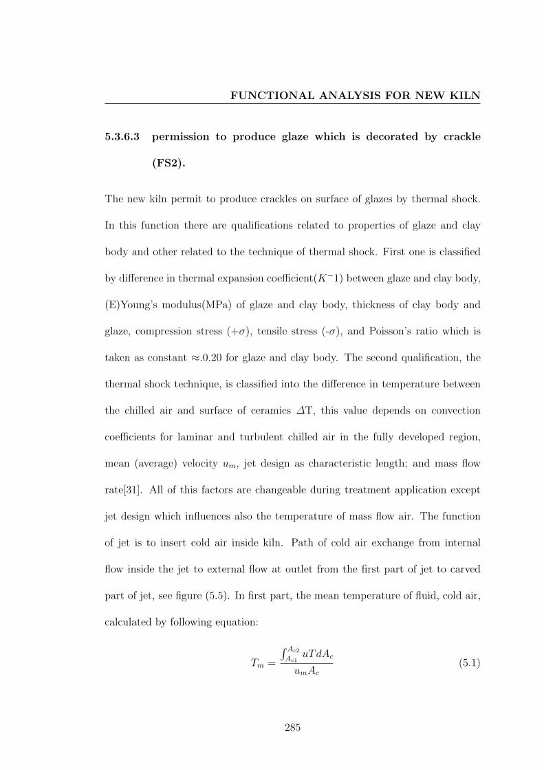
FUNCTIONAL ANALYSIS FOR NEW KILN
5.3.6.3 permission to produce glaze which is decorated by crackle
(FS2).
The new kiln permit to produce crackles on surface of glazes by thermal shock.
In this function there are qualifications related to properties of glaze and clay
body and other related to the technique of thermal shock. First one is classified
by difference in thermal expansion coefficient(K−1) between glaze and clay body,
(E)Young’s modulus(MPa) of glaze and clay body, thickness of clay body and
glaze, compression stress (+σ), tensile stress (-σ), and Poisson’s ratio which is
taken as constant ≈.0.20 for glaze and clay body. The second qualification, the
thermal shock technique, is classified into the difference in temperature between
the chilled air and surface of ceramics ∆T, this value depends on convection
coefficients for laminar and turbulent chilled air in the fully developed region,
mean (average) velocity um, jet design as characteristic length; and mass flow
rate[31]. All of this factors are changeable during treatment application except
jet design which influences also the temperature of mass flow air. The function
of jet is to insert cold air inside kiln. Path of cold air exchange from internal
flow inside the jet to external flow at outlet from the first part of jet to carved
part of jet, see figure (5.5). In first part, the mean temperature of fluid, cold air,
calculated by following equation:
Tm =
∫ Ac2
Ac1uTdAc
umAc(5.1)
285

DESIGN KILN FOR THERMAL SHOCK AND CHEMICALTREATMENTS
. In jet, there are to areas Ac, one is the area of large circular surface Ac1 and
other is the area of small circular surface of air channel inside the jet, see figure
(5.5). Therefore, air inside the jet has two different region of boundary layer with
asymmetrical temperature profile, due to the difference of surface area between
large circular surface A1 and small circular surface A2 , where this lead to differ-
ence in convection coefficients and convective heat flux. Therefore the diffusion
of T(r) in the vicinity of large circular surface is not similar to diffusion of T(r)
in the vicinity of small circular surface which lead to change the carve of tem-
perature profile of air as shown in figure (5.4). the shape of relative temperature
profile of cold air in circular tube before inter to jet is demonstrated in figure (5.4
a)) and it is changed inside jet as in (5.4 b)).
The mean temperature is fluid reference temperature used to calculate the
convection heat rate from the surface of jet to fluid air, Newton’s law of cooling
and the overall energy balance is used to do this calculation :
q′′s = q′′conv = h(Ts − Tm) (5.2)
Therefore, the convection heat rate affect in temperature profile of cold air,
as well as relation between surface temperature Ts and mean temperature Tm.
The Ts to surface jet is inconstant where it increased in direction of inside kiln.
Accordingly, the mean temperature varies linearly with x along jet tube, (Ts -
Tm) increases with x along jet tube which maintains the temperature profile to
286

FUNCTIONAL ANALYSIS FOR NEW KILN
Figure 5.4: relative temperature profile of cold air a) in circular tube b) in jet
[31].
inter the kiln with T(r) and Tm less than the temperature inside the kiln. The
different temperature between Tm an T inside kiln will increased with duration of
air injection where q′′conv will decries because Ts will decries. The figure (5.5) shows
plan section of jet with details; a) the profile of vicinity; b) thermal boundary
layer and temperature profile for injected air in jet; c) the convex shape of part
of jet with narrow outlet to create long laminar for cold air inside the kiln based
upon Coanda effect. It has been taking into account that the surface area has
been reduced as much as possible especially in hot zone by slender form for path
way of cold air in jet.
287

DESIGN KILN FOR THERMAL SHOCK AND CHEMICALTREATMENTS
Fig
ure
5.5
:S
ecti
onp
lan
ofd
evel
oped
des
ign
ofje
tw
ith
det
ails
ofh
eat
tran
sfer
,te
mp
eratu
rean
dvic
init
yp
rofi
led
uri
ng
air
inje
ctio
n,
and
des
ign
ofco
nve
xsu
rfac
eof
jet
and
the
outl
eth
ole.
288

FUNCTIONAL ANALYSIS FOR NEW KILN
5.3.6.4 permission to change the conditione of firing process (FS3).
The new kiln permit to change the condition of firing from neutral atmosphere to
reduction and/or sulphidation. In these functions there are qualifications related
to temperature of treatment and its duration on firing schedule, state of materials
which are used to change the atmosphere of kiln, the quantity of these materials
and there relation to kiln construction. The criterions of these qualifications
depend on design solution for construction of kiln which allows to do this function,
see figure (5.6). This solution is an architectural design, the mean idea of this
design depends on rotation part of kiln wall. This part should be free to rotate
around ball-and-socket fulcrum, and it can be designed from intersection of such
circular form with wall of kiln. The circular form permit to rotate and the axis
of this rotation is (x1 ) as seen in figure (5.6), which slant on UCS horizontal
axis by angle equal 69◦. It intersects with UCS vertical axis inside kiln wall in
intersection point which permits to remain part of cylinder diameter out of the
wall thickness. Wall of cylinder is designed by another circular inside the large
circular form. The small circular axis is (x2 ) which is shifted from (x1 ) by 1.18
cm in direction of outside the kiln. Therefore cross section of cylinder wall is
crescent and it thickness decreased gradely from 4 cm to 1.5 cm which permits
to shift empty space inside the cylinder in direction of outside the kiln to keep
large part of this space as possible outside the intersection with kiln wall.
289

DESIGN KILN FOR THERMAL SHOCK AND CHEMICALTREATMENTS
Fig
ure
5.6
:S
ecti
onp
lan
ofto
olw
hic
his
des
ign
edto
chan
geco
nd
itio
nof
firi
ng
by
soli
dm
ate
rials
290

FUNCTIONAL ANALYSIS FOR NEW KILN
The intersection part of empty space inside cylinder with the kiln wall transfer
in solid part to form a free part of wall kiln that its position is changed with
rotation to make the empty space in hot zone. The remaining form of empty
space inside cylinder, the gradient shape in figure (5.6), is form of materials that
is used to change the atmosphere of kiln. This form in position a) in figure (5.6)
keep the materials in temperature of outside the kiln. Therefore atmosphere
of kiln remains natural until it changes to position b) where the materials are
brought in temperature of inside the kiln. Therefore, these materials will melt
and enter to firing chamber from the hole designed in kiln wall in front of another
hole in cylinder wall, this in case of used solid materials who change the condition
of atmosphere. In case of liquid materials like water the hole is designed on tope
of cylinder as shown in figure (5.7). The volume of empty space in cylinder
determine the maximum of volume of water and weight of sulfur and rosin. This
volume related to geometric design for new kiln, the diameter of cylinder and
thickness of kiln wall. This design solution permits to do this treatment in any
duration in schedule of firing, and therefore, all types of ceramics which required
redaction atmosphere can produced in this kiln as well as the types which required
natural atmosphere and types which required the new treatments of sulphidation.
291

DESIGN KILN FOR THERMAL SHOCK AND CHEMICALTREATMENTS
Fig
ure
5.7
:S
ecti
onp
lan
ofto
olw
hic
his
des
ign
edto
chan
geco
nd
itio
nof
firi
ng
liquid
mate
rials
292

FUNCTIONAL ANALYSIS FOR NEW KILN
5.3.6.5 Respect the chemical reactions conditions and physical prop-
erties (FC1).
the qualifications of chemical reactions conditions and physical properties, which
must be taken into account for using kiln as a tool for affect in ceramics sur-
faces, are classified into alteration related to condition of firing and other related
materials of kiln construction. The ideal temperature for making treatments is
determined according to which reaction is prepared. The reaction of H2O with
carbon gas C above 900 C produce heat and force reduction atmosphere.
C + H2OCO + H + Q
The reaction of S, H, and C with glaze produce esthetic treatments. Histor-
ical techniques which discussed in Section (2.3), Ellingham Diagram and Phase
diagram of copper-iron-sulfur system which discussed in Section( 4.5.2, and 4.5.4)
are used for determining the temperature of treatments.
Materials of kiln construction should be resistant withstand high sulphur,
reducing atmospheres. The ”ABLE CAST 3000” ∗ is a cast refractory which is
suitable for kiln construction especial for inside layer. Heating elements should be
stable with carbon gases, sulfured gazes and humidity, the silicon carbide heating
element work successfully under these conditions. The dilatation line of materials
∗produced by ABLE Supply Company in USA, and its composition and properties is men-
tioned in appendix A.6
293

DESIGN KILN FOR THERMAL SHOCK AND CHEMICALTREATMENTS
which is used in kiln construction also should be taken in account with design of
the rotation cylinder and all moving parts of kiln.
5.3.6.6 Adapt to the environment (FC2).
The gases which get out from kiln as SO2 and CO2 is treated by H2O and NaCl
to change gas form of sulfur into Na2SO3 salted form and CO2 change from gas
form into salted form Na2CO3.
SO2 + H2O−→H2SO3 + H ↑
H2SO3 + 2NaCl−→Na2SO3 + HCl ↑
CO2 + H2O + 2NaCl−→Na2CO3 + HCl ↑
The quantity of H2O and NaCl are calculated from these reactions.
5.3.6.7 Design appropriate construction of kiln (FC3).
Construction of kiln should has some qualifications to achieve the serves functions.
Therefore, they are represented in tight close during the firing to prevent gases
and smoke from leaking to outside air, distribute gases and smoke inside the kiln
and conceive a construction in order to permit to gases and smoke to leak in H2O
and NaCl. Tight closing necessitated that design the kiln as an elevator kiln as
shown in figure (5.8) , where a) is position when the kiln is closed and b) is the
position when kiln is open. The long outlet of smoke and design three obstacles
294

FUNCTIONAL ANALYSIS FOR NEW KILN
prevent leaking of gases, so it get out only from treating unit. Ball valves is used
to close the outlets of jet.
295

DESIGN KILN FOR THERMAL SHOCK AND CHEMICALTREATMENTS
Fig
ure
5.8
:se
ctio
np
lan
ofn
ewkil
na)
the
pos
itio
nw
hen
the
kil
ncl
osed
and
b)
the
posi
tion
wh
enkil
nop
en
296

FUNCTIONAL ANALYSIS FOR NEW KILN
Figure 5.9: The masonry illustration of pointed arch which is used to design h
thatched of kiln
For distritbuting smoke and gasses, kiln was designed cylinder form, and it
was thatched by pointed dome that its section plan is pointed arch like it is used
in roman kiln which is mentioned in section (2.5.2). The geometric illustration
of this arch is shown in figure(5.9). According to movement of smoke and gasses,
inserting solid materials inside the kiln is designed to be from the bottom of the
kiln, then naturally vapors and smoke take them place to go up from right side
until the top of pointed dome then it return to slow down for get out from holes
that designed in left side in the bottom of kiln. Therefore, the kiln is designed
as down-draft to distritbute the vapor and smoke, as shown in figure(5.10). This
is based on the the historical study, refer to figures (2.53, and 2.51). Vapors
and gases are drafted down from the firing chamber to the treating unit which is
297

DESIGN KILN FOR THERMAL SHOCK AND CHEMICALTREATMENTS
Figure 5.10: Schematic demonstrate down draft and distribution of smoke and
gasses in new kiln
designed to keep gasses in closed outlet until they are treated in water and salts.
5.3.6.8 Respect of the standards of thermal insulation (FC4).
The standards of thermal insulation is related to heat flow in the kiln walls,
and their criterions determine the resistances power of heating elements which
are necessary for heating kiln to required temperature 1300 C. There are some
qualifications, which should be taken in account to compleat the design of new
kiln, the thermal resistance R (m2.K /W) of kiln walls’, thermal connectivity of
kiln wall materials λ (WK−1m−1),and the thickness of kiln wale (m). The shape
298

FUNCTIONAL ANALYSIS FOR NEW KILN
of kiln is related to this factors where the surfaces of wall is a significant factor
in heat transfer as well as boundary temperatures of each part of kiln walls.
Heat flow by conduction in such direction x calculate from Fourier’s law of
conduction[156] is expressed as flowing:
ϕx = −λδTδx
(5.3)
the thermal flow density (W/m2) is calculated by flowing equation:
ϕ
∫ e
0
dx = −λ∫ T2
T1
dT (5.4)
and with integration it is equal to:
ϕ =λ
e(T1 − T2) (5.5)
the thermal resistance in (m2.K.W−1) is calculated by flowing equation:
Rcd =(T1 − T2)
ϕ=e
λ(5.6)
and in case of multi layer of insulation martials with different thermal conduc-
tively, the power loss en (W/m2) is calculated by flowing equation:
ϕ =
(1
e1λ1
+ e2λ2
+ ... enλn
)(T1 − T2) (5.7)
The kiln structure is composed from three parts; first is the base, a wall in circle
form , second is cylinder form and the third part is pointed dome. According to
heat flow through layer plan, which is calculated by following equation:
φ = ϕ.S = −λ.S.dTdx
(5.8)
299

DESIGN KILN FOR THERMAL SHOCK AND CHEMICALTREATMENTS
Therefore, the power loss by (W) through base of kiln calculated from following
equation:
φ1 =λ× (T1 − T2)
e× S =
λ× πr2 × (T1 − T2)
e(5.9)
Where the (λ) is thermal conductivity of kiln wall (W.m−1.K−1), (S) is the
area of wall surface(m2), T1 is the internal temperature, T2 is the external tem-
perature, (r) is the radius of the base of kiln and (e) is thickness (m), and thermal
resistance R1 (KW−1) for first part, if it is composed from one layer, is calculated
from following equation:
R1 one layer =(T1 − T2)
φ1=
e
λ× πr2(5.10)
and in case of multi layer of insulation materials with different thermal conduc-
tivity, the power loss en (W) is calculated by flowing equation:
φ = πr2
(1
e1λ1
+ e2λ2
+ ... enλn
)(T1 − Tn) (5.11)
So the thermal resistance of first part R1 (KW−1), if it is composed from
multi layer, is calculated from following equation:
R1 multi layer =1
πr2×Rcd =
1
πr2×(e1
λ1+e2
λ2+ ...
enλn
)(5.12)
,and the temperature (K) between two layers is calculated from following
equation:
Ti = Ti−1 −(Φi−1
πr2
)×(eiλi
)(5.13)
300

FUNCTIONAL ANALYSIS FOR NEW KILN
In the second part of kiln which is a cylinder form, the density of thermal
flow is given also by Fourier’s law of conduction[156], but the area of cylinder is
given by 2πLr where the L is a length of cylinder wall and r is radius of cylinder.
Therefore the power loss (w) in this part can be determine as flowing equations:
φ2 = −λ.2π.Lr.δTδx
(5.14)
∫ T2
T1
dT =−φ2
λ.2π.L
∫ r2
r1
dr
r(5.15)
Φ2 =λ2πL
ln(r2r1
) × (T1 − T2) (5.16)
The thermal resistance of second part R2 (KW−1)if it is composed from one layer,
is calculated from following equation:
R2 one layer =(T1 − T2)
φ2=
ln(r2r1
)λ× 2πL
(5.17)
for identify the relation between Rcd and R2,where r1 is internal radius of cylinder,
r2 is is external radius of cylinder, and (r2 − r1) is the thickness of kiln wall in
this part, the following equation is used to determine R2 :
R2 one layer =(r2 − r1)
λ2πL (r2−r1)
ln(
r2r1
) = Rcd ×1
2πL (r2−r1)
ln(
r2r1
) (5.18)
when wall of kiln composed of multi layer the power loss in (W) calculated
301

DESIGN KILN FOR THERMAL SHOCK AND CHEMICALTREATMENTS
from flowing equation:
Φ2 multi layer =2π.L× (T1 − Tn)[
1λ1× ln
(r2r1
)+ 1
λ2× ln
(r3r2
).. 1λn× ln
(rn+1
rn
)] (5.19)
,and the R2 (KW−1) of wall which composed of multi layer is calculated from
flowing equation:
R2 multi layer =
[1λ1× ln
(r2r1
)+ 1
λ2× ln
(r3r2
).. 1λn× ln
(rn+1
rn
)]2π.L
(5.20)
the temperature in (K) between two layer is calculated from following equation:
Tn+1 = Tn −Φ ln
(rn+1
rn
)2πλn
(5.21)
The third part is an pointed dome which is formed from an arch which revolve
around the vertical axes (y) in center of the kiln. This arc is a part of circle as
shown in figure (5.9), this part of arch who create the surface area of dome as
shown in figure (5.11). Since the surface area of pointed dome is a surface of
revolution, the equation of revolved curve is required which is have relation with
mean circle in figure (5.11). The circle equation with center (0,0) is as following:
f(y) =√r2 − y2 (5.22)
Since the arc is part of circle but the center is different, the equation of arch will
be a modified to circle equation to adapt with new center (3.94,1.67), therefore
the variable value of (y) in circle equation is increased by a when r is radius of
302
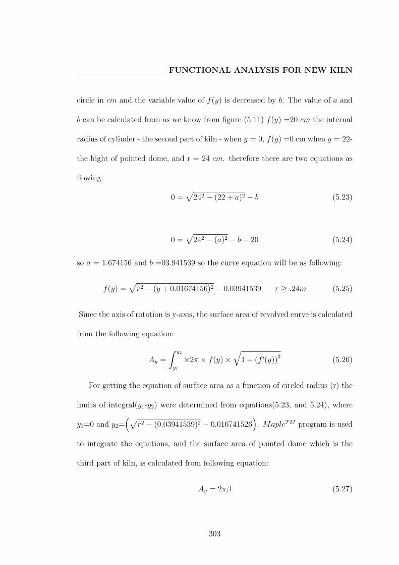
FUNCTIONAL ANALYSIS FOR NEW KILN
circle in cm and the variable value of f(y) is decreased by b. The value of a and
b can be calculated from as we know from figure (5.11) f(y) =20 cm the internal
radius of cylinder - the second part of kiln - when y = 0, f(y) =0 cm when y = 22-
the hight of pointed dome, and r = 24 cm. therefore there are two equations as
flowing:
0 =√
242 − (22 + a)2 − b (5.23)
0 =√
242 − (a)2 − b− 20 (5.24)
so a = 1.674156 and b =03.941539 so the curve equation will be as following:
f(y) =√r2 − (y + 0.01674156)2 − 0.03941539 r ≥ .24m (5.25)
Since the axis of rotation is y-axis, the surface area of revolved curve is calculated
from the following equation:
Ay =
∫ y2
y1
×2π × f(y)×√
1 + (f ′(y))2 (5.26)
For getting the equation of surface area as a function of circled radius (r) the
limits of integral(y1-y2) were determined from equations(5.23, and 5.24), where
y1=0 and y2=(√
r2 − (0.03941539)2 − 0.016741526)
. MapleTM program is used
to integrate the equations, and the surface area of pointed dome which is the
third part of kiln, is calculated from following equation:
Ay = 2πβ (5.27)
303

DESIGN KILN FOR THERMAL SHOCK AND CHEMICALTREATMENTS
Figure 5.11: Illustration to determine the equation of arc from relation between
the arc and mean circle
where
β =(0.03941539 arcsin
(0.01674126
r
)r)
+9.920644763 10−7 r
×√
1.016061984 1012 r2 − 1.578526434 109 − 0.01674126001 r
−0.03941539000 r × arcsin(8.596485169 10−20(1.154035000 1013
√1.016061984 1012 r2−1.578526434 109−1.60271841 108)
r
)r∗≥0.24
Therefore in this part the power loss Φ3 in (W), if wall composed from one layer
can be determine as flowing equations:
Φ3 =2πλ(T1 − T2)∫ r2
r1( 1β)dr
(5.28)
∗r is radius of main circle of arch
304

FUNCTIONAL ANALYSIS FOR NEW KILN
,and when wall of kiln composed from multi layer the power loss in (W) calculated
from flowing equation:
Φ3 multi layer =2π.× (T1 − Tn)[
1λ1×(∫ r2
r1( 1β)dr)
+ 1λ2×(∫ r3
r2( 1β)dr).. 1λn×(∫ rn+1
rn( 1β)dr)](5.29)
the temperature in (K) between two layer is calculated from following equation:
Tn+1 = Tn − Φ3 ×
(∫ rn+1
rn( 1β)dr)
2πλn(5.30)
Total power loss ΦTotal for the kiln is equal to the sum of three power loss Φ1
, Φ2 and Φ3 so the power of the resistors can be proposed to be twice that power
loss, as well as thermal resistance Rtotal can be obtained from following equation:
1
Rtotal=
1
R1+
1
R2+
1
R3
the power loss will be equal to 1524 (W/m2) if the the thermal resistance is equal
to 0.84(m2KW−1), and maximum temperature is equal 1300 C, so the thick-
ness of wall layers and temperatures between them can be determined when we
place in order this layer according to, their thermal conductively, their maximum
temperature limit, their method of lining and their mechanical properties.
5.3.6.9 Respect of properties of refractory materials which are se-
lected for building the construction of kiln (FC5).
This constraint function is related to determine the suitability of refractory mate-
rials with serves functions of new kiln, where refractory castables are required to
305

DESIGN KILN FOR THERMAL SHOCK AND CHEMICALTREATMENTS
forme the architectural construction of kiln, and the refractory fibres are required
to reduce the weight, especially the elevated top part. Therefore the deformation
of refractory castables and lining of refractory fibres are important issue to select
refractory materials for new kiln, along with standards of thermal insulation and
they are used together to determine thickness of kiln.
According to standards of thermal insulation and Respect the chemical re-
actions conditions, ”Able cast 3000” refractory castable (A.6) is chosen for first
layer from inside the kiln and second layer is ”Firelite 2500TM” A.7 refractory
castable. This choice is due to their mechanical properties. All these materials
have suitable performances in high temperature, the permanent linear change in
(%) of Firelite 2500TM is negative and the permanent linear change of Able cast
3000 is positive above 1200 C, and therefore they are chosen to be the first two
layers in face of high temperature to avoid deformation in refractory castables,
which are the supports to maintain the architectural construction of kiln. As
well as thermal linear expansion of two refractory castables should be taken in
account to avoid deformation in structure.
The permanent linear change in (%) is presented as function of temperature
in product information (A.6, and A.7), and therefore, thermal expansion linear
is required to present also in(%) to be compared with permanent linear change.
Then the difference between permanent linear change, which exists only in first
firing, and thermal expansion at 1300 C (the maximum temperature )and 20 C
306

FUNCTIONAL ANALYSIS FOR NEW KILN
(the room temperature) create two stats of deformation: the first when kiln work
at 1300 C; the second when kiln is at room temperature.
Thermal expansion coefficient of refractories as function of temperature can
be calculated according to their chemical composition by following equation[32]:
α = (10−8 ×B) + (2× 10⁻¹⁰ × C × T ) + (3× 10⁻¹⁴ ×D × T 2) (5.31)
where B , C and D are constants calculated according to the data in table
(A.8) as function of chemical composition of refractor. and the ∆LT in% can be
expressed by the following equation:
∆LT% = 100×(10−8×B)+(2×10⁻¹⁰×C×T )+(3×10⁻¹⁴×D×T 2)×(T −293)
(5.32)
So the ∆LT in (%)of Firelite 2500TM , the change in length owing to Thermal
expansion can be calculated as function of temperature (K) by the following
equation:
∆LT% dialitation Firelite 2500 = 100× (10−8 × (4.23522164))
+ (2× 10−10 × (18.1683977)× T )
− (3× 10−14 × (11.29010320)× T 2)
×(T − 293)
(5.33)
Figure (5.12) shows the curve of thermal linear expansion in (%) of Firelite
2500TM as function of temperature in K . The change in length owing to perma-
307

DESIGN KILN FOR THERMAL SHOCK AND CHEMICALTREATMENTS
Figure 5.12: Impermanent curve of ∆ L % of Firelite 2500TM as function of
temperature K
nent linear change for Firelite 2500TM can be calculated as function of tempera-
ture in K by the following equation:
∆LT% permanent Firelite 2500 =
(−0.01)− (0.2× 10⁻⁴ × T ) + (10−7 × T 2)
−(10−10 × T 3)− (8× 10⁻¹⁴ × T 4)
(5.34)
The figure (5.13)shows the curve of the permanent linear change in (%)of Firelite
2500TM as function of temperature in K .
The ∆LT in (%)of Able cast 3000, the change in length owing to Thermal
expansion can be calculated as function of temperature in K by the following
308

FUNCTIONAL ANALYSIS FOR NEW KILN
Figure 5.13: permanent curve of ∆ L % of Firelite 2500TM as function of tem-
perature K
equation:
∆LT % dialitation of Able cast 3000 = 100× (10−8 × (3.995475703))
+ (2× 10−10 × (18.52137357)× T )
− (3× 10−14 × (10.3635449)× T 2)
×(T − 293)
(5.35)
Figure (5.14) shows the curve of thermal linear expansion in (%) of as Able cast
3000 function of temperature (K). The change in length owing to permanent
linear change of Able cast 3000, can be calculated as function of temperature in
K in duration from 1505 K to 1670 K by the following equation:
∆LT % permanent of Able cast 3000 = 0.310−2T − 4.8242 [1505, 1670]
(5.36)
309
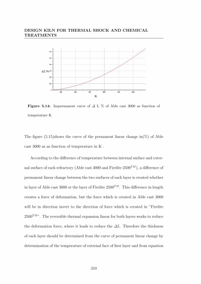
DESIGN KILN FOR THERMAL SHOCK AND CHEMICALTREATMENTS
Figure 5.14: Impermanent curve of ∆ L % of Able cast 3000 as function of
temperature K
The figure (5.15)shows the curve of the permanent linear change in(%) of Able
cast 3000 as as function of temperature in K .
According to the difference of temperature between internal surface and exter-
nal surface of each refractory (Able cast 3000 and Firelite 2500TM), a difference of
permanent linear change between the two surfaces of each layer is created whether
in layer of Able cast 3000 or the layer of Firelite 2500TM . This difference in length
creates a force of deformation, but the force which is created in Able cast 3000
will be in direction invert to the direction of force which is cerated in ”Firelite
2500TM”. The reversible thermal expansion linear for both layers works to reduce
the deformation force, where it leads to reduce the ∆L. Therefore the thickness
of each layer should be determined from the curve of permanent linear change by
determination of the temperature of external face of first layer and from equation
310

FUNCTIONAL ANALYSIS FOR NEW KILN
Figure 5.15: Permanent curve of ∆L% of Able cast 3000 as function of temper-
ature (K).
(5.36) the ∆LAblecastexternal will be calculated in external face of ”Able cast 3000”
layer, and difference between ∆LAble cast internal and ∆LAble cast external should be
equal to the difference between ∆LFirelite 2500 internal and ∆LFirelite 2500 external.
The temperature inside Firelite 2500 is the same than the one of external face
of ”Able cast 3000”. The ∆LFirelite 2500 internal is calculated from equation (5.34),
and the temperature of external face of ”Firelite 2500” layer is calculated from
the same equation by the difference of ∆L between the internal and external
face of Firelite 2500 layer. Once the temperatures of faces and between layers are
known the thickness of each layer can be calculated from equation (5.5) where the
heat flow is 1524 (W/m2) and the thermal conductivity of ”Able cast 3000” is 1.2
311

DESIGN KILN FOR THERMAL SHOCK AND CHEMICALTREATMENTS
(W.m−1.K−1) at 1300 C and it is 0.44 (W.m−1.K−1) above 1000 C for ”Firelite
2500”. The suitable thickness for cylinder and base parts which is calculated from
the balance between permanent linear change of two refractories , in addition to
static young’s modulus. ”Firelite 2500TM” ,according to ASTM C401-91[157],
is a regular castable refractory, where it has a total lime (CaO) content greater
than 2.5 % and total alumina (Al2O3) content 44.4%, see (A.7). ”Able cast 3000”
is an insulating castable refractory, where it has a total alumina (Al2O3) content
60.17% (A.6). Therefore these monolithics refractories are alumina and alumino-
silicate castable refractories which can specify their static young’s modulus as
function in temperature from figure (5.17). Therefore the Young’s modulus of
”Able cast 3000” is 8× 10⁶ psi (47.6 GPa ) at 20 C, and it is 4.7× 10⁶ psi (32.4
GPa) at 20 C.
The thickness of ”Able cast 3000” can be 17 mm and the thickness of ”Firelite
2500” can be 26 mm to avoid deformation in wall. In pointed dome part, the wall
thickness of the first two layers must be less thicker than the wall thickness of the
first two layers of base, owing to the weight of elevated part of kiln. The thickness
of refractory castables in this part can be 10 mm of ”Able cast 3000” and 14 mm
of ”Firelite 2500”, its weight is 9.6 kg and it is designed to be supported by 12
anchors as shown in figure(5.16).
Deformation force in dimensions of concrete layers can be calculated by deter-
mined the difference between external and internal temperature where equations
312

FUNCTIONAL ANALYSIS FOR NEW KILN
Figure 5.16: Section plan of pointed dome with anchors which hold the dome
part of kiln
(5.33, 5.34, 5.35, and 5.36) defined the relation between temperature and ∆Lsh∗
, and also ∆Ld †. In addition the temperature in layer thickness can be defined
from equation (5.5). From this equations ∆Ltotal can be calculated as the sum
of ∆Ld and ∆Lsh. The ∆Ltotal is in maximum value, when kiln is at 20 C. To
study the resistance of designed thickness of this castable refractories to defor-
mation, the ANSYS programme ( finite element program ) is used to simulate
the mechanical deformations. . .
The surfaces forces which are created from change in vertical linear, are cal-
∗∆Lsh is a permanent liner change†∆Ld is a reversible dilatation
313

DESIGN KILN FOR THERMAL SHOCK AND CHEMICALTREATMENTS
Figure 5.17: Static Young’s modulus as function in temperature for monolithics
refractories [32]
314

FUNCTIONAL ANALYSIS FOR NEW KILN
culated from the flowing equation:
Fv = S.E(∆L
h) (5.37)
where Fv is vertical force (N), S surface aria (m2) E Young’s modulus(Pa),
∆L the difference in length (m), and h is length or hight (m). The surfaces forces
which are created from change in horizontal linear, is calculated from the flowing
equation:
Fh = S.G(∆e
e) (5.38)
where Fh is horizontal force (N), S is a surface aria (m2) G Shear modulus (Pa), ∆e
the difference in thickness (m), and e is thickness (m). The table (5.2) introduce
the related data to cylinder and base which are inserted to ANSYS program to
simulate the total deformations. The equivalent stress and stress intensity, where
the thickness of ”Able cast 3000” and ”Firelite 2500TM” is different than the
thickness of dome for the same materials, and table (5.2) introduce also the data
for pointed dome, top part of kiln. These data is calculate to simulate the surface
forces after heating the kiln to first time at 1300 C and return to 20 C.
The total deformations result for cylinder and base parts is shown in figures
(5.18),and for the pointed dome is shown in figure (5.21). The maximum of
total deformations are in external edges of ”Able cast 3000” layer in front of
internal edges of ”Firelite 2500TM”. The height values of deformations are in top
edge of cylinder because it is not contacted with flat surface as its base. The
315

DESIGN KILN FOR THERMAL SHOCK AND CHEMICALTREATMENTS
Table 5.1: The required data to simulate the total deformations,equivalent stress
and stress intensity in two parts cylinder and base
Information Able cast 3000 layer Firelite 2500TM layer
Internal External Internal External
Thickness e 17 mm 26 mm
Length L 320 mm 320 mm
Temperature 1300 C 1278 C 1278 C 1187 C
∆Lsh -0.1% -0.17% -0.64% -0.5%
∆Ld 0.65% 0.63% 0.61% 0.53%
∆esh −0.49 10−3 % −0.683 10−3 % −0.39 10−2 % −0.33 10−2 %
Surface force Cylinder wall
Fv at 20 C -5.17 105 N -9.15 105 N -3.77 106 N -3.24 106 N
Fh at 20 C -3.75 104 N -5.66 104 N -2.26 105N -2.15 105 N
Circle base wall
Fv at 20 C -2.93 104 N -4.08 104 N -2.33 105 N -1.97 105 N
Fh at 20 C 2.03 105 N 3.45 105 N 1.99 106 N 1.55 106 N
horizontal deformation can be considered in equilibrium to choice this thickness
as two first layers in structure of kiln wall. The equivalent stress and stress
intensity results as shown in figure (5.19) and figure (5.20) refer to equilibrium
between the thickness of two layers. While in pointed dome the deformation
is height values of deformations are equilibrium,and equivalent stress and stress
intensity results as shown in figure (5.22) and figure (5.23) refer to equilibrium
between the thickness. therefore these proposed thicknesses are applicable to
316

FUNCTIONAL ANALYSIS FOR NEW KILN
Table 5.2: The required data to simulate the total deformations,equivalent stress
and stress intensity in dome part of kiln
Information Able cast 3000 layer Firelite 2500TM layer
Internal External Internal External
Thickness e 10 mm 14 mm
Temperature 1300 C 1287 C 1287 C 1238 C
∆Lsh -0.1% -0.14% -0.65% -0.57%
∆Ld 0.65% 0.64% 0.61% 0.58%
∆esh −0.027 10−3 % −0.034 10−3 % −0.22 10−2 % −0.204 10−2 %
Pressure Pointed dome wall
Pv at 20 C -4.76 107 Pa -6.66 107 Pa -1.98 108 Pa -1.85 108 Pa
Ph at 20 C -5.13 103 Pa -6.46 103 Pa -2.86 105 Pa -2.60 105 Pa
construction of new kiln. The concrete refractory which is the internal
structure of kiln in the cylinder and base is composed of 17 mm thickness of
”Able cast 3000” with thermal conductivity (λ) 1.202 (W.m−1.K−1), and 26 mm
thickness of ”Firelite 2500TM” with thermal conductivity (λ) 0.44 (w.m−1.K−1).
So, the temperature in external surface of this two layers will be 1187C when
kiln is at 1300 C [equation (5.7)]. So the thickness of kiln’s wall in this parts
can be completed by refractory fiber and other castable refractory to create a
temperature profile which is shown in figure (5.24). The third layer is designed
to be 25 mm of ”Cerachrome TM Blanket” with thermal conductivity λ equal
0.25 (W.m−1.K−1) to change temperature from 1187 C in internal side to 1035 C
317

DESIGN KILN FOR THERMAL SHOCK AND CHEMICALTREATMENTS
Figure 5.18: Result of total deformations in first two layers of cylinder and circle
base which are designed to cast from 17 mm of ”Able cast 3000” and 26mm ”Firelite
2500TM”
318

FUNCTIONAL ANALYSIS FOR NEW KILN
Figure 5.19: Result of equivalent stress in first two layers of cylinder and circle
base of kiln structure
319

DESIGN KILN FOR THERMAL SHOCK AND CHEMICALTREATMENTS
Figure 5.20: Result of stress intensity in first two layers of cylinder and circle
base of kiln structure
320

FUNCTIONAL ANALYSIS FOR NEW KILN
Figure 5.21: Result of total deformations in first two layers of pointed dome
which are designed to cast from 10 mm of ”Able cast 3000” and 14 mm ”Firelite
2500TM”
321

DESIGN KILN FOR THERMAL SHOCK AND CHEMICALTREATMENTS
Figure 5.22: Result of equivalent stress in first two layers of pointed dome of kiln
structure
322

FUNCTIONAL ANALYSIS FOR NEW KILN
Figure 5.23: Result of stress intensity in first two layers of pointed dome of kiln
structure
323

DESIGN KILN FOR THERMAL SHOCK AND CHEMICALTREATMENTS
in external side.∗. The fourth layer is ”Superwool TM” 607 TM Blanket” with
λ equal 0.25 (W.m−1.K−1) so 50 mm thickness of this materials is proposed to
reduce wall thickness, and change temperature from 1035 C in internal side to
527 C in external side.∗. The fifth layer is designed to be in hard concrete in
order to be in contact with the tool of change atmosphere in zone of temperature
less than 550 C where the liner change of Firecrete 95 is nearly constant to -0.1%
and its resistance to compression is 60.8 MPa at this temperature ∗. This layer
designed to be 30 mm,and it is used to lining fiber refractory. In this layer the
temperature change from 527 in internal side to 499 C in external side where it
λ is 1.6 (W.m−1.K−1). The last layer is designed of ”Therminap 322-550” with
low thermal conductively 0.037 therefore 12 mm thickness is sufficient to change
temperature from 499 C in internal side to 20 C in external side. So the total
thickness of refractories is 160 mm. . The wall in pointed dome is designed in
different order, where most of wall thickness in this part designed to be from
refractory fiber. The thickness of first two layers in this part is 24 mm to change
temperature from 1300 C inside the kiln to 1238 C in external side of this two
layer, the third layer is a 120 mm of ”Cerachrome TM Blanket” to change the
temperature from 1238 C to 477 C and the last layer of refractories is desiend to
be 12 mm of ”Therminap 322-550”, so the total thickness of refractories in this
∗The temperature limit of this material is 1424 C.(A.9)∗The temperature limit of this material is 1100 C. (A.10)∗The information data of this material is mentioned in (A.17)
324

FUNCTIONAL ANALYSIS FOR NEW KILN
Figure 5.24: The temperature profile in wall of cylinder and base parts of kiln,
and the order of refractory materials
part is 161 mm.
5.3.6.10 Respect of heating standards (FC6).
This function is related to determine electric resistance of heating elements which
are required for new kiln. So, the accurate electric power which is used for heating
the kiln up to 1300 C is required, and the power for new kiln is 2670 W, so two
elements of silicon carbide are designed in parallel to be the heating elements of
new kiln. Silicone carbide elements which are recommended to use in this kiln,
do not have a specific rating in watts, but the rated power is function of high
required temperature and surface loading of element (W.cm2) as mentioned in
KanthalGlobarr SD technical data [33].
325

DESIGN KILN FOR THERMAL SHOCK AND CHEMICALTREATMENTS
The recommended form to new kiln is CU as shown in figure (5.25), cold ends
C is equal to base thickness 160 mm , hot zone B lengths is 260 mm , short end
E with aluminum is 40 mm, and the diameter A of legs is 16 mm. Therefore
the surface loading of elements recommended to new kiln is 5 W.cm2, where it is
calculated by equation (5.39) and the temperature of each element is 1365 C as
mentioned in recommended element loading for KanthalGlobarr SD operated in
air, is shown in figure (5.26).
surface loading = π × A×B (5.39)
Where A is the outer diameter in cm and B is the length of hot zone in cm. the
site of elements should be at minimum of 1.5 diameter between element center
and any adjacent refractory.
5.4 conception of kiln
The determinants of design are known during the study of serves function and
external milieu elements. Kiln can be used as a tool to enrich the aesthetic
of glaze colors and texture as before in traditional ceramics but with modern
technology, and for applying new technique of crackle and metallic reflation. The
three cylinders, the tools of changing atmosphere, are charged by material and
waiting for change cylinders position, then the solid materials will melt and flow
326

CONCEPTION OF KILN
Figure 5.25: Silicone carbide elements in form CU with two leg which is recom-
mended to new kiln
327

DESIGN KILN FOR THERMAL SHOCK AND CHEMICALTREATMENTS
Figure 5.26: Chart of surface loading in function of kiln temperature and element
temperature(recommended for Kanthal GLOBAR SD operated in air) [33].
328

CONCEPTION OF KILN
inside the kiln through a breach which is designed in wall, as water will evaporate
also inside the kiln through a tube. This function was design solutions which
become executable design in following conception and plan.
329

DESIGN KILN FOR THERMAL SHOCK AND CHEMICALTREATMENTS
Fig
ure
5.2
7:
Con
cep
tion
ofn
ewkil
n
330

CONCEPTION OF KILN
Fig
ure
5.2
8:
Pla
nof
new
kil
n
331

DESIGN KILN FOR THERMAL SHOCK AND CHEMICALTREATMENTS
5.5 Conclusions
Ceramic kiln can be modified from just a place of heating to a place of create
reactions which give ceramics their beauty under condition of heating and atmo-
sphere of heating. This modification was related to historical study and scientific
study, and it is achieved in conception which permits to change the condition
of firing by dint of design solution, and in order to apply some traditional firing
method and new technique of crackle and metallic reflection colors. The behavior
of refractories materials which are proposed to build kiln structure is simulated
by ANSYS program to test the possibility of producing this kiln, and rustles of
this simulation confirmed that this conception of kiln can be produced.
332

Conclusions and Perspectives
In this chapter, the main relation between history, art, technology and science
are recalled and concern the results of historical and scientific study. The main
contributions of this thesis are presented. In addition, some proposals for further
research directions are introduced.
Concluding Remarks
History of ceramics and their scientific conception have to consider the existence
of two different disciplines, as the art and sciences. They were separated in
Renaissance period. With recognition of this difference, there are common issues
between science and human sciences, and research in these issues that can enrich
both of them. This interface study concerned with researching the history of kiln
technology and firing conduction with the relative effects on aesthetic treatments
of ceramics form. Developed technologies lead to improve ceramics technology
as well as kiln technology, the order which leads to disappear or modify some
333

CONCLUSIONS AND PERSPECTIVES
technologies, and to produce others. This is what was discovered from historical
and scientific study for two historical ceramics types. The first type, with metallic
reflection decoration, which appeared in Iraq during Abbasid Caliphate period
(750-1258), and the reduction atmosphere of kiln was the main procedure to
produce this color. This technology was transferred to Egypt then to north
of Africa then to Spain and Italy. During transferring of this technology, its
firing condition was changed from redaction to oxidation. The second type, is
technology of produce five famous kilns in China during the Sung dynasty (690-
1279). Therefore, the reaction atmosphere and structure of kiln affect mainly the
production of these styles of ceramics.
As evidenced by historical study that the scientific progress in chemistry of
ceramics play important role in producing artificial porcelain in France, England,
and Germany. M.Bronghiart mentioned to this role of chemistry in improving the
art of ceramics and its applications, as well as color of glaze. This role has had a
positive impact in enriching the esthetic treatments in industrial of ceramics and
in expressive ceramics art.
This study is related to science and technology of ceramics , where it aims
to determine design of kiln that can be used as tool to enrich the aesthetic of
ceramics. This is achieved by selecting treatments that can occur during firing,
and influencing positively on glaze color. Additionally, scientific study presents
the explanation of traditional technology to improve it as a modern technology
334

CONCLUSIONS AND PERSPECTIVES
of decorate ceramics.
Throughout the thesis, correlations between art, science, history and history
of ceramic technology in referring to kiln technology are introduced to explain
the philosophy of this recherche. whereas, it is interface research between these
disciplines, so relative importance of general factors which affect in productions
of promotional ceramics can be defined to classify the traditional styles of ce-
ramics which are decorated by treatments during or after firing process. The
relation between ceramics and these disciplines presents a vision about the ben-
efit of correlation between them especially between kiln technology and esthetic
treatments of ceramics forms. History of ceramic technology demonstrate devel-
opment in materials, and production technologies which are necessary to design
and produce ceramics, while science presents materials analysis methods, chem-
icals reactions and physical properties which explain technology of this styles.
According to traditional styles of ceramics, treatments during firing was classi-
fied to atmosphere of kiln as referring to amount of oxygen, and condition of firing
as referring to heating rate and inserting vapor of substances. kiln structure and
heating technology determine treatments which can be carried out during firing.
For recognizing styles of firing condition in ceramics history, the classification
of different types of ceramics art and pottery as presented by M.Brongniart was
studded. Carbon atmosphere of firing was produced in primitive firing and in fuel
kilns. The structure of recognized primitive firing affects in degree of reduction
335
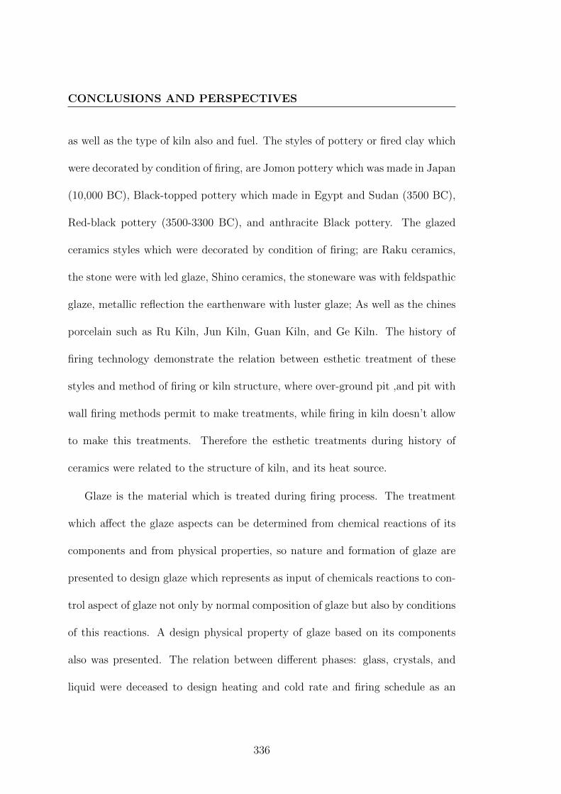
CONCLUSIONS AND PERSPECTIVES
as well as the type of kiln also and fuel. The styles of pottery or fired clay which
were decorated by condition of firing, are Jomon pottery which was made in Japan
(10,000 BC), Black-topped pottery which made in Egypt and Sudan (3500 BC),
Red-black pottery (3500-3300 BC), and anthracite Black pottery. The glazed
ceramics styles which were decorated by condition of firing; are Raku ceramics,
the stone were with led glaze, Shino ceramics, the stoneware was with feldspathic
glaze, metallic reflection the earthenware with luster glaze; As well as the chines
porcelain such as Ru Kiln, Jun Kiln, Guan Kiln, and Ge Kiln. The history of
firing technology demonstrate the relation between esthetic treatment of these
styles and method of firing or kiln structure, where over-ground pit ,and pit with
wall firing methods permit to make treatments, while firing in kiln doesn’t allow
to make this treatments. Therefore the esthetic treatments during history of
ceramics were related to the structure of kiln, and its heat source.
Glaze is the material which is treated during firing process. The treatment
which affect the glaze aspects can be determined from chemical reactions of its
components and from physical properties, so nature and formation of glaze are
presented to design glaze which represents as input of chemicals reactions to con-
trol aspect of glaze not only by normal composition of glaze but also by conditions
of this reactions. A design physical property of glaze based on its components
also was presented. The relation between different phases: glass, crystals, and
liquid were deceased to design heating and cold rate and firing schedule as an
336

CONCLUSIONS AND PERSPECTIVES
operation during firing according to network of glaze. Glaze structure expression
is presented with limitation of glaze formula. The chemical treatment of ancient
metallic reflection glazes and celadon glaze were presented to recognize their glaze
composition as discovered by previous studies, as well as its colorant. Where, the
composition of ancient glaze can be concluded to propose a raw material from
their oxide analysis. The physical treatment of glaze that can produce crackle
on surface was presented to design the glaze which can be treated by this aspect.
Thus, the theoretical calculation of glaze properties and chemical formula was
reorganized to prepare the accurate glaze for such procedures during firing for
enriching its esthetic.
Furthermore, calculating glaze structure from oxides analysis was experi-
mented to simulate the Ru kiln sample, and it can be concluded that this sample
has porcelain body which resisted thermal shock and it has low thermal expansion
coefficient. Therefore, the experimental study to simulate porcelain body and its
glaze is significant to produce the clay body and glaze which are suitable to treat
by thermal shock as a mechanical treatment. In addition, this study was led to
design method to make thermal shock during cooling period. As for the chemicals
treatments, method of design glaze permit to prepare glazes which are suitable
to react with atmosphere of kiln for producing metallic phases of iron and copper
as traditional technique. This metallic phase was designed to react with sulphi-
dation atmosphere to produce sulfide iron-copper ores which give glazes different
337

CONCLUSIONS AND PERSPECTIVES
colors. The Ellingham diagram and Cu:Fe:S system is used to regulate the rela-
tion between the glaze structure and the temperature of sulphidation treatment.
Therefore, using kiln as tool to controls chemical reactions are modification to
historical techniques that can be used today to create new method for gilding
surface of ceramics glazes. This is in addition to some others colors as black with
a metallic luster, indigo blue, and peacock ore. These are results of design all
of glazes as chemical materials, treatments during firing as condition of reaction,
and kiln structure to apply the treatments during firing.
In order to apply these new and traditional techniques, the conception of new
kiln should be designed for permitting to treat glazed forms by thermal shock and
chemical treatments. The process of conception was presented by APTE method
for determination of the study boundaries, the requirements, utilization phase,
and octopus diagram of new kiln. The service function which links between the
kiln and elements of external milieu (EME), are presented to solve all problems
and describe details of kiln.
Conclusion
1. Correlations between art, science, history and history of ceramic technology
in referring to kiln technology are demonstrated.
2. Treatments during fairing were existed in many civilizations over history of
338

CONCLUSIONS AND PERSPECTIVES
ceramics technology.
3. Historical study was important to limit materials that can be used to im-
prove the tremens during firing as well as improve the kiln technology.
4. Chemical of glaze was important to identify and understand the ancient
technology and reproduce it today, as well as to know the reaction during
firing.
5. Phases diagrams of Iron copper and sulfur were the main guide to defined
the temperature and reactions to create new technique during firing.
6. Mechanical properties of refractory was an issue to improve the kiln tech-
nologies.
7. Design solution permit to modify technology of firing when the history
information and scientific knowledge are available .
Future Work
Future work should explore other possibilities and routes in which this thesis
could lead to more enriching for ceramics esthetic. Main perspectives should
include:
• The implementation of this kiln:
Due to the possibility of producing metallic reflections, gilding, and crackle
339

CONCLUSIONS AND PERSPECTIVES
decorations by this kiln, the implementation of this kiln is necessary. The
techniques of thermal shock and chemical shock required this kiln, so the
experimental study of this these technologies have to continue for applying
this techniques and specifying actual palettes and range of colors as function
of treatment during firing and glaze compositions. This will leads to discover
other uncertainties parameters.
Additionally, search for other metallic ores could be led to other esthetic
treatments especial with method of design glaze and using each of Ellingham
diagram phase’s diagrams. Where this searching can lead to adapt tech-
nological production of such color of glaze, or to create new treatments,
Where the condition of firing under control used by implementation of new
kiln.
• Verification and evaluation of using technique of crackle in pres-
ence of technique of chemical treatments:
The proposed crackle by using thermal shock could be verified and assessed
in presence of chemical treatment to create colored crackle. Research on the
compatibility between the resistance of thermal shock and thermal expan-
sion coefficient of glaze and clay body could be led to produce decoration
by drawing of crackle on glazed form.
• Recommendation to more scientific and experimental research on
340

CONCLUSIONS AND PERSPECTIVES
the history of ceramics techniques :
Scientific and experimental research on the history of ceramics techniques
could be considered as a deriving for artistic practices and applied ceram-
ics, as well as it leads to discover and provide evidence about traditional
techniques.
341


Appendix A
Table A.1: chemical analysis for some clay bodies from Iraq which are covered by luster
metallic expressed in oxide percent and normalized to 100%.
Sample Number SiO2 Na2O MgO Al2O3 K2O CaO TiO2 MnO FeO PbO
FUA. 06 51.60 1.20 5.90 11.90 0.90 19.80 0.70 0.40 6.10 0.00
FUA. 23 50.10 1.00 6.40 12.10 0.70 21.50 0.60 0.30 6.40 0.00
FUA. 26 50.10 1.30 6.40 11.90 1.00 21.30 0.60 0.30 5.90 0.00
FUA. 25 50.30 0.20 6.30 12.10 1.10 21.10 0.80 0.30 6.40 0.00
FUA. 07 49.50 1.50 6.00 12.00 0.80 21.50 0.70 0.20 6.20 0.00
343

Tab
leA
.2:
chem
ical
anal
ysi
sfo
rso
me
clay
bod
ies
from
Kai
rou
anw
hic
har
eco
vere
dby
lust
erm
etall
icex
pre
ssed
in
oxid
ep
erce
nt
and
nor
mal
ized
to10
0%(∆
isth
est
and
ard
dev
iati
on)
Sam
ple
Nu
mb
erN
a2O
MgO
Al 2
O3
SiO
2P2O
5S
Cl
K2O
CaO
TiO
2F
e 2O
3
BD
X5051
∆
1.0
3
0.1
2
6.9
4
0.4
8
12.1
4
0.4
4
49.0
4
2.4
2
1.2
8
0.4
3
0.3
2
0.0
9
0.0
9
0.0
3
1.2
4
0.1
2
20.3
1
1.3
3
0.6
9
0.1
4
6.5
8
0.4
1
BD
X6474
∆
0.6
6
0.2
1
6.0
5
0.3
4
11.5
3
0.5
1
44.7
5
0.8
5
2.6
5
0.3
0
0.0
0
0.0
0
0.1
6
0.0
8
1.9
8
0.5
8
22.0
5
0.6
8
1.1
9
0.5
1
9.0
0
0.8
1
BD
X6476
∆
0.7
3
0.2
0
6.0
8
0.2
5
11.8
4
0.1
8
47.0
9
0.8
2
2.4
6
0.2
5
0.7
2
0.1
8
0.1
9
0.0
6
2.0
0
0.2
8
21.3
5
0.7
8
0.7
4
0.0
9
6.7
0
0.2
1
BD
X5052
∆
0.9
2
0.3
1
6.9
5
0.5
7
12.8
0
0.8
4
47.9
5
1.6
1
0.7
1
0.5
6
0.2
4
0.0
6
0.2
4
0.0
8
1.5
3
0.2
2
21.0
4
1.6
7
0.6
8
0.0
4
6.5
9
0.3
9
BD
X6473
∆
0.8
5
0.0
7
6.2
7
0.1
9
11.6
7
0.2
3
47.5
1
0.5
2
1.1
7
0.1
4
0.0
0
0.0
0
0.0
0
0.0
0
1.4
6
0.1
2
22.5
3
0.3
6
0.6
9
0.0
3
7.8
5
0.2
0
BD
X6475
∆
0.7
8
0.2
4
6.0
5
0.2
6
12.0
0
0.3
9
47.4
0
1.8
8
1.4
7
0.2
6
0.0
5
0.1
3
0.1
9
0.0
4
1.5
5
0.3
7
22.1
9
1.3
4
0.7
5
0.0
7
7.4
6
0.4
6
BD
X6477
∆
2.1
1
0.4
9
7.8
8
0.5
4
11.2
0
0.6
8
45.2
6
2.0
2
0.0
0
0.0
0
0.0
0
0.0
0
1.1
6
0.5
1
1.8
2
0.4
6
22.0
8
1.5
6
0.7
1
0.0
5
7.7
9
0.4
2
BD
X6478
∆
0.6
1
0.0
7
6.3
3
0.1
9
12.1
5
0.2
3
48.5
5
0.5
2
1.3
9
0.1
4
0.0
0
0.0
0
0.0
0
0.0
0
1.7
0
0.1
2
20.6
7
0.3
6
0.7
2
0.0
3
7.8
8
0.2
0
344

Tab
leA
.3:
chem
ical
anal
ysi
sof
glaz
esw
ith
met
alli
cre
flec
tion
from
Kai
rou
anex
pre
ssed
inox
ide
per
cent
an
dn
orm
ali
zed
to10
0%(∆
isth
est
and
ard
dev
iati
on)
Sam
ple
Nu
mb
erN
a2O
MgO
Al 2
O3
SiO
2P2O
5C
lK
2O
CaO
Mn
OF
e 2O
3S
nO
2P
bO
BD
X5051
∆
7.6
4
0.8
1
3.4
8
0.2
7
2.1
3
0.9
7
66.8
7
1.8
4
0.0
0
0.0
0
0.6
9
0.0
6
3.0
2
0.2
0
4.7
0
0.2
8
0.4
3
0.0
7
0.7
9
0.1
0
2.6
3
0.7
1
6.9
2
0.8
6
BD
X6474
∆
5.7
3
0.2
2
2.9
5
0.2
8
1.5
8
0.5
3
65.9
5
1.2
2
2.4
9
0.2
5
0.6
9
0.0
7
3.0
5
0.1
4
4.8
4
0.3
2
0.4
7
0.0
6
1.0
6
0.3
4
1.7
9
0.9
7
9.2
7
0.8
4
BD
X6476
∆
6.6
8
0.7
0
3.8
4
0.6
4
1.8
8
0.4
8
66.6
7
0.7
3
0.8
1
0.6
1
0.6
4
0.0
6
3.1
4
0.3
5
5.6
3
1.0
7
0.4
9
0.0
4
0.9
7
0.3
5
1.7
4
0.8
0
7.4
2
1.2
0
BD
X5052
∆
7.7
9
0.4
0
3.3
2
0.3
6
1.5
8
0.4
3
67.4
4
2.1
0
0.0
0
0.0
0
0.7
4
0.0
8
2.8
8
0.2
0
4.4
3
0.4
6
0.4
5
0.0
5
0.7
3
0.0
9
3.0
2
0.8
5
6.8
7
0.7
8
BD
X6473
∆
7.0
2
0.4
5
3.2
7
0.5
6
1.8
1
0.6
8
68.0
8
2.7
5
0.3
4
0.4
8
0.7
0
0.0
6
3.1
8
0.2
4
4.5
6
1.0
1
0.3
9
0.0
6
0.9
4
0.3
5
2.3
9
0.9
8
7.2
5
0.7
1
BD
X6475
∆
7.2
9
0.3
6
3.3
8
0.4
5
1.6
9
0.4
3
66.6
6
0.8
2
0.7
8
0.4
6
0.7
2
0.0
7
3.5
6
0.1
6
4.8
8
0.6
7
0.4
8
0.1
0
0.7
5
0.0
5
1.6
9
0.7
5
8.1
2
0.4
8
BD
X6477
∆
7.2
3
0.1
9
3.4
2
0.1
9
1.4
6
0.2
4
65.0
0
1.2
6
0.0
0
0.0
0
0.5
9
0.0
6
3.8
5
0.1
4
4.9
5
0.3
1
0.3
9
0.0
4
0.7
5
0.1
0
4.3
1
1.9
9
8.0
5
0.9
4
BD
X6478
∆
7.3
5
0.3
5
3.3
0
0.4
6
1.7
7
0.6
1
66.5
1
1.6
9
0.9
9
0.1
4
0.7
4
0.0
3
2.9
7
0.0
8
4.7
1
0.6
4
0.4
5
0.0
7
0.8
3
0.1
1
2.9
2
1.5
9
7.4
7
0.6
3
345

Table A.4: chemical analysis of Iraq luster metallic glaze expressed in oxide
percent and normalized to 100%.
Sample Number SiO2 PbO Na2O K2O CaO Al2O3 SnO2 MgO FeO
FUA. 06 54.50 14.40 5.80 4.10 3.60 1.80 13.10 2.20 0.50
FUA. 23 56.60 10.10 6.50 4.70 4.10 1.90 12.20 3.30 0.50
FUA. 26 59.30 8.00 7.00 4.70 4.30 2.20 10.60 3.40 0.60
FUA. 25 60.60 7.80 8.70 4.10 4.10 1.60 9.00 3.50 0.70
FUA. 07 65.30 5.80 6.40 3.40 7.30 1.20 6.50 2.40 0.50
Table A.5: chemical analysis of some kinds of wood ,normalized to 100%.
Designation
of wood fuel
Carbon C Hydrogen H Nitrogen N Oxygen O Ashes
Oak wood 50.44 6.01 1.06 42.49 1.69
Birch wood 51.30 6.28 0.00 41.54 0.85
Aspen wood 50.35 6.28 0.82 42.55 2.11
Fir wood 50.59 6.11 1.04 41.26 1.29
Pine wood 51.71 6.11 0.81 41.37 1.15
346

Table A.6: chemical analysis of some kinds of lignite ,normalized to 100%
Designation Carbon C Hydrogen H Oxygen O
and Nitrogen N
Ashes
Uznach lignite 57.29 5.83 36.88 2.19
Basses-Alpes lignite 72.19 5.36 22.45 3.01
Elbong lignite 77.64 7.85 14.51 4.96
Table A.7: chemical analysis of some kinds of coal ,normalized to 100%
Designation Carbon C Hydrogen H Oxygen O
and Nitrogen N
Ashes
Saint-Girons coal 76.05 5.69 18.26 4.08
Blanzy coal 78.26 5.35 18.39 2.28
Lancashire coal 85.81 5.85 8.34 2.55
Newcastel coal 89.19 5.31 5.50 1.40
Alais coal 90.55 4.92 4.53 1.41
347
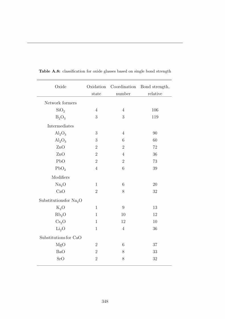
Table A.8: classification for oxide glasses based on single bond strength
Oxide Oxidation Coordination Bond strength,
state number relative
Network formers
SiO2 4 4 106
B2O3 3 3 119
Intermediates
Al2O3 3 4 90
Al2O3 3 6 60
ZnO 2 2 72
ZnO 2 4 36
PbO 2 2 73
PbO2 4 6 39
Modifiers
Na2O 1 6 20
CaO 2 8 32
Substitutionsfor Na2O
K2O 1 9 13
Rb2O 1 10 12
Cs2O 1 12 10
Li2O 1 4 36
Substitutions for CaO
MgO 2 6 37
BaO 2 8 33
SrO 2 8 32
348

Tab
leA
.9:
Tem
per
ature
equ
ival
ents
for
Ort
onst
and
ard
larg
eco
nes
.S
ourc
e:A
mer
ican
Cer
amic
Soci
ety.
Low
-tem
per
atu
rera
ng
Mid
dle
-tem
per
atu
rera
ng
Hig
h-t
emp
erat
ure
ran
g
Con
en
oh
eati
ng
rate
Con
en
oh
eati
ng
rate
Con
en
oh
eati
ng
rate
150
C/h
r27
0F
/hr
150
C/h
r27
0F
/hr
150
C/h
r27
0F
/hr
C.0
1089
4C
1641
FC
.411
86C
2167
FC
.812
63C
2305
F
C.0
992
3C
1693
FC
.511
96C
2185
FC
.912
80C
2336
F
C.0
895
5C
1751
FC
.612
22C
2232
FC
.10
1305
C23
81F
C.0
798
4C
1803
FC
.712
40C
2264
FC
.11
1315
C23
99F
C.0
699
9C
1830
FC
.12
1326
C24
19F
C.0
510
46C
1915
FC
.13
1346
C24
55F
C.0
410
60C
1940
FC
.14
1366
C24
91F
C.0
311
01C
2014
FC
.15
1431
C26
08F
C.0
211
20C
2048
F
C.0
111
37C
2079
F
C.1
1154
C21
09F
C.2
1162
C21
24F
C.3
1168
C21
34F
349

Table A.10: temperature equivalent for Seger standard cones ,source: Staatliche
prozellan-manufaktur, Berlin
Low-temperature rang Middle-temperature rang High-temperature rang
Cone no Cone no Cone no
022 595 C 2a 1150 C 7 1260 C
021 894 C 3a 1170 C 8 1280 C
020 923 C 4a 1195 C 9 1300 C
019 955 C 5a 1215 C 10 1320 C
018 984 C 6a 1240 11 1340 C
017 999 C
016 1046 C 12 1360 C
015a 1060 C 13 1380 C
014a 1101 C 14 1400 C
013a 835 C 15 1425 C
012a 860 C
011a 900 C
010a 920 C
09a 935 C
08a 955 C
07a 970 C
06a 990 C
05a 1000 C
04a 1025 C
03a 1055 C
02a 1085 C
01a 1105 C
1a 1125 C
350

Table A.11: A Cross Reference List Of Comparable Frits
Pemco O-Hommel Ferro
P-54 14 3134
P-25 25 3269
P-830 K-3 3278
Pb-723 437 3403
Pb-63 24 3417
Pb-83 33 3419
Pb-1307 11 3470
Pb-1151 27 3482
Pb-801 520 3485
Pb-716 3489
Pb-742 373 3493
Pb-IK-75 474 3532
Pb-349 3565
P-311 90 3124
P-1409 3249
P626 400 3289
P-802 378 3270
Pb-IR40 3471
595 3496
351

Tab
leA
.12:
Sta
nd
ard
glaz
efr
its
inor
der
ofF
usi
onte
mp
erat
ure
from
Fer
roC
omp
any
,Com
posi
tion
inE
qu
ivale
nt
Fri
tM
ol
Fu
sion
Coeff
.
no.
wt
tem
p,
of
K2O
Na2O
Li 2
OC
aO
MgO
BaO
SrO
Zn
OP
bO
Al 2
O3
B2O
3Z
rO2
SiO
2T
iO2
F
Fex
p
3453
257.4
850
6.8
1.0
00
0.4
31
0.0
7
3419
270.8
1000
8.8
0.2
82
0.7
18
0.5
64
0.9
0
3476
352.5
1050
7.1
1.0
00
1.0
00
1.0
0
3435
302.1
1300
7.5
0.0
45
0.2
12
0.3
93
0.3
50
0.0
65
0.7
07
2.1
4
3485
335.1
1300
7.7
0.3
33
0.6
67
0.6
66
1.9
8
3545
275.6
1300
7.3
0.0
40
0.0
86
0.4
84
0.3
90
0.0
94
0.4
39
1.8
7
3369
331.7
1300
9.0
0.5
02
0.4
98
1.0
04
1.9
9
3191
248.7
1300
9.2
0.5
01
0.4
99
1.0
02
2.0
0
3227
372.9
1300
9.8
0.1
62
0.8
38
0.5
68
1.5
26
2.3
6
3205
235.5
1320
11.4
0.1
98
0.4
83
0.3
19
0.2
86
0.3
08
1.9
7
3185
807.2
1350
6.0
1.0
00
4.4
30
7.2
7
3223
505.6
1350
7.6
1.0
00
2.0
00
5.0
7
3470
232.0
1350
7.5
0.0
84
0.2
30
0.2
58
0.4
28
0.1
23
0.2
83
1.0
7
3403
307.0
1350
7.2
0.0
47
0.0
17
0.0
04
0.9
32
0.0
69
1.4
3
3457
235.1
1350
7.6
0.0
34
0.3
50
0.6
16
0.0
53
1.1
7
3482
365.5
1400
8.3
0.1
52
0.1
59
0.2
12
0.4
77
0.3
18
2.6
20.4
42
0.4
24
3824
235.8
1400
8.3
0.3
46
0.1
88
0.4
65
0.9
88
1.6
2
3264
291.6
1400
11.0
0.9
84
0.0
05
0.0
11
0.1
92
0.8
85
2.4
7
3278
270.6
1400
9.7
0.6
69
0.3
31
0.8
42
2.5
3
3823
257.7
1400
9.7
0.6
21
0.3
79
0.7
94
2.3
7
3819
328.0
1400
10.3
0.2
50
0.6
90
0.0
19
0.0
41
0.4
04
0.7
82
2.6
10.2
64
3269
354.5
1400
11.4
0.3
06
0.6
41
0.0
09
0.0
44
0.4
62
0.7
78
2.9
50.3
00
3417
382.4
1400
6.7
0.0
77
0.0
95
0.3
06
0.5
22
0.1
13
0.6
91
0.0
75
2.7
8
3516
236.1
1400
7.6
0.0
44
0.0
40
0.5
17
0.0
01
0.3
98
0.0
61
0.4
42
1.2
4
Conti
nu
edon
nex
tp
age
352

Table
A.12
–continued
from
previouspage
Fri
tM
ol
Fu
sion
Coeff
.
no.
wt
tem
p,
of
K2O
Na2O
Li 2
OC
aO
MgO
BaO
SrO
Zn
OP
bO
Al 2
O3
B2O
3Z
rO2
SiO
2T
iO2
F
Fex
p
3110
260.6
1400
10.1
0.0
64
0.6
43
0.2
93
0.0
94
0.0
98
3.0
3
3226
587.0
1450
6.3
0.6
93
0.3
07
0.0
52
3.0
67
5.1
3
3221
399.1
1450
9.4
0.1
75
0.8
12
0.0
13
0.6
91
1.5
01
2.6
1
3134
190.5
1450
9.6
0.3
16
0.6
84
0.6
32
1.4
7
3454
710.4
1450
5.5
0.1
25
0.2
15
0.3
74
0.0
87
3.1
23
4.8
5
3361
509.0
1450
5.9
0.0
55
0.2
17
0.3
54
0.3
74
0.0
87
2.2
38
3.7
0
3304
382.5
1500
6.6
0.0
67
0.9
33
0.1
49
2.5
8
3489
248.3
1500
7.3
0.2
48
0.7
52
1.1
0
3271
247.9
1500
9.3
0.5
14
0.4
86
0.7
68
2.2
5
3287
374.0
1500
8.2
0.3
33
0.6
67
0.2
00
0.6
67
3.0
7
3270
274.0
1500
9.4
0.1
59
0.3
80
0.4
61
0.2
32
0.6
48
2.3
4
3814
225.7
1500
8.9
0.0
09
0.3
15
0.6
76
0.1
10
0.6
24
1.8
7
3193
271.5
1500
9.0
0.0
74
0.4
07
0.5
19
0.2
08
0.6
10
2.4
4
5301
247.2
1500
11.6
0.1
34
0.7
65
0.1
01
0.2
74
0.4
18
1.7
21.1
51
3240
207.2
1500
8.6
0.0
12
0.1
52
0.3
26
1.1
07
0.4
03
0.0
18
0.2
95
0.1
72
1.3
60.2
09
3493
373.3
1500
6.7
0.0
77
0.0
95
0.3
05
0.5
23
0.1
13
0.6
91
2.7
7
3576
339.9
1500
7.1
0.2
11
0.2
88
0.5
01
0.1
18
0.6
67
0.0
22
2.2
8
3471
258.1
1500
8.0
0.0
71
0.0
22
0.3
02
0.2
52
0.3
53
0.0
98
0.4
55
1.2
3
3519
270.8
1500
8.2
0.0
93
0.3
38
0.0
07
0.3
10
0.2
51
0.1
44
0.4
24
1.9
2
3293
342.6
1550
8.9
0.9
22
0.0
12
0.0
66
0.2
00
4.3
6
3224
1022.0
1600
5.8
0.8
79
0.0
51
0.0
70
0.9
13
3.8
50
10.0
0
3241
921.0
1600
4.5
0.1
52
0.8
36
0.0
12
0.2
20
2.2
20
11.3
6
3815
274.6
1600
7.2
0.2
70
0.2
05
0.5
25
1.2
00
2.0
0
353

Tab
leA
.13:
wei
ght
frac
tion
ofea
chox
ides
com
pon
ents
ofR
uG
uan
porc
elain
bod
y(R
GP
D)
Cod
eC
om
pen
sati
ng
oxid
esan
aly
sis
of
Ru
porc
elain
bod
yw
eight
fract
ion
of
each
oxid
esco
mp
on
ents
No
Nam
eB
od
yco
lor
Al 2
O3
SiO
2K
2O
CaO
TiO
2M
nO
Fe 2
O3
LO
IA
l 2O
3S
iO2
K2O
CaO
TiO
2M
nO
Fe 2
O3
R40b
RG
PD
ash
ygra
y27.9
866.7
51.8
00.5
31.1
70.0
21.7
527.5
665.7
41.7
70.5
21.1
50.0
21.7
3
R41b
RG
PD
ash
ygra
y26.6
067.0
52.2
10.7
41.1
0.0
22.2
726.2
166.0
62.1
80.7
31.0
80.0
22.2
4
R42b
RG
PD
ash
ygra
y28.4
666.2
41.7
60.3
81.3
00.2
1.8
428.0
365.2
51.7
30.3
81.2
80.0
21.8
1
R43b
RG
PD
ash
ygra
y30.6
263.2
11.5
41.4
91.0
70.0
42.0
330.1
662.2
61.5
21.4
71.0
50.0
42.0
0
R44b
RG
PD
ash
ygra
y27.2
766.7
81.9
30.4
21.1
50.0
22.4
326.8
665.7
71.9
00.4
21.1
30.0
22.3
9
R47b
RG
PD
ash
ygra
y30.5
762.7
92.2
01.3
71.1
50.0
11.9
130.1
161.8
42.1
71.3
51.1
30.0
11.8
8
R271b
RG
PD
ash
ygra
y27.1
867.2
71.8
50.4
41.2
90.0
01.9
726.7
766.2
61.8
20.4
41.2
70.0
01.9
4
R275b
RG
PD
ash
ygra
y27.0
667.3
11.8
90.6
11.2
50.0
11.8
726.6
666.3
11.8
60.6
01.2
30.0
11.8
4
R330b
RG
PD
ash
ygra
y32.2
361.8
71.8
00.8
51.1
20.0
02.1
331.7
560.9
41.7
70.8
41.1
00.0
02.1
0
R333b
RG
PD
ash
ygra
y32.2
662.4
81.5
70.5
71.1
0.0
02.0
231.7
861.5
41.5
50.5
61.0
80.0
01.9
9
R339b
RG
PD
ash
ygra
y30.5
663.7
01.4
61.0
91.2
10.0
21.9
630.1
062.7
41.4
41.0
81.1
90.0
21.9
3
R382b
RG
PD
ash
ygra
y27.3
965.8
11.9
41.8
31.2
00.0
31.8
026.9
864.8
31.9
11.8
01.1
80.0
31.7
8
354

Tab
leA
.14:
wei
ght
frac
tion
ofea
chox
ides
com
pon
ents
ofR
uG
uan
gla
ze
Cod
eC
om
pen
sati
ng
oxid
esan
aly
sis
of
Ru
porc
elain
bod
yw
eight
fract
ion
of
each
oxid
esco
mp
on
ents
No
Nam
eB
od
yco
lor
Al 2
O3
SiO
2K
2O
CaO
TiO
2M
nO
Fe 2
O3
LO
IA
l 2O
3S
iO2
K2O
CaO
TiO
2M
nO
Fe 2
O3
R40b
RG
PD
ash
ygra
y27.9
866.7
51.8
00.5
31.1
70.0
21.7
527.5
665.7
41.7
70.5
21.1
50.0
21.7
3
R41b
RG
PD
ash
ygra
y26.6
067.0
52.2
10.7
41.1
0.0
22.2
726.2
166.0
62.1
80.7
31.0
80.0
22.2
4
R42b
RG
PD
ash
ygra
y28.4
666.2
41.7
60.3
81.3
00.2
1.8
428.0
365.2
51.7
30.3
81.2
80.0
21.8
1
R43b
RG
PD
ash
ygra
y30.6
263.2
11.5
41.4
91.0
70.0
42.0
330.1
662.2
61.5
21.4
71.0
50.0
42.0
0
R44b
RG
PD
ash
ygra
y27.2
766.7
81.9
30.4
21.1
50.0
22.4
326.8
665.7
71.9
00.4
21.1
30.0
22.3
9
R47b
RG
PD
ash
ygra
y30.5
762.7
92.2
01.3
71.1
50.0
11.9
130.1
161.8
42.1
71.3
51.1
30.0
11.8
8
R271b
RG
PD
ash
ygra
y27.1
867.2
71.8
50.4
41.2
90.0
01.9
726.7
766.2
61.8
20.4
41.2
70.0
01.9
4
R275b
RG
PD
ash
ygra
y27.0
667.3
11.8
90.6
11.2
50.0
11.8
726.6
666.3
11.8
60.6
01.2
30.0
11.8
4
R330b
RG
PD
ash
ygra
y32.2
361.8
71.8
00.8
51.1
20.0
02.1
331.7
560.9
41.7
70.8
41.1
00.0
02.1
0
R333b
RG
PD
ash
ygra
y32.2
662.4
81.5
70.5
71.1
0.0
02.0
231.7
861.5
41.5
50.5
61.0
80.0
01.9
9
R339b
RG
PD
ash
ygra
y30.5
663.7
01.4
61.0
91.2
10.0
21.9
630.1
062.7
41.4
41.0
81.1
90.0
21.9
3
R382b
RG
PD
ash
ygra
y27.3
965.8
11.9
41.8
31.2
00.0
31.8
026.9
864.8
31.9
11.8
01.1
80.0
31.7
8
355

A.0.1 Calculating partes by of kaolin d’Arvor to give parts
by weight of composition oxides for porcelain body
According to chemical analysis of kaolin d’Arvor in table (4.6) the 100 parts by
weight of kaolin d’Arvor give 12.85 parts by weight of H2O, 47.15 parts by weight
of SiO2, 37.6 parts by weight of Al2O3, 0.95 parts by weight of K2O, < 0.1 parts by
weight of CaO, 0.09 parts by weight of TiO2, < 0.02 parts by weight of MnO, and
0.78parts by withe of Fe2O3. so for preparing such batch recipe which contained
30.57% of Al2O3, the required partes by weight of Kaolin calculated as following:
(100 × 30.57) ÷37.6 = 81.3 partes by weight of Kaolin.
Therefore
81.3 parts by weight of kaolin d’Avron −→ 30.57 parts by weight of Al2O3 which
is required to simulate recipe of R47b sample. 81.3 parts by weight of kaolin
d’Avron gives parts by weight of others composition oxides which are calculated
as following:
100 parts by weight of kaolin d’Arvor −→ 12.85 parts by weight of H2O.
So 81.3 gram of kaolin gives (81.3 × 12.85) ÷100 = 10.45 gram ofH2O. 1 mole
of H2O = 18.016 gram, so the 81.3 give 0.58 mole of H2O The volume of gas
calculated from following equation:
V =nRT
P(A.1)
356

where V is volume in m3, n is units mole, R is ideal gas constant (8.32 J K−1),
T temperature in kelvin and P is the absolute pressure in units Pascals(101300
Pa). The volume of 0.58 mole of H2O vapor at 20 C which is presented by 81.38
gram of kaolin is 13.9 liter.
A.0.2 Calculating partes by weight of potassium carbon-
ate to give parts by weight of potassium oxide for
porcelain body
Potassium carbonate decomposes into CO2 and K2O as 138.21g K2CO3 −→ 94.2g
K2O + 44.01g CO2
The purity of Potassium carbonate which used is K2CO3 99% + 0.0005% Fe.
1.43 parts by weight of K2O is obtained from parts by weight of K2CO3 which is
calculated as following:
(1.43 × 138.21) ÷94.2 = 2.10 parts by weight of K2CO3. 2.10 parts by weight of
K2CO3 gives (2.10 × 44.01) ÷138.21 = 0.67 parts by weight of CO2. 1 mole of
CO2 = 44.01 gram , so the 0.67 gram of carbon dioxide is equal to 0.015 mole
of CO2. The volume of 0.015 mole of CO2 gas at at 800 C which is presented by
2.10 gram of potassium carbonate is 1.32 liter.
357

A.0.3 Calculating partes by weight of calcium carbonate
to give parts by weight of calcium oxide for porce-
lain body
Calcium carbonate decomposes into CO2 and CaO as,
100.09g CaCO3 −→ 56.08g CaO + 44.01g CO2
The purity of Potassium carbonate which used is CaCO3 99% + 0.001% Fe
1.29 parts by weight of CaO is obtained from parts by weight of CaCO3 which is
calculated as following:
(1.29 × 100.09) ÷56.08 = 2.30 parts by weight of CaCO3. 2.30 parts by weight
of CaCO3 gives (2.30 × 44.01) ÷ 100.09 = 1.01 parts by weight of CO2. 1 mole
of CO2 = 44.01 gram, so the 1.01 gram f carbon dioxide is equal to 0.023 mole of
CO2.The volume of 0.023 mole of CO2 gas at 800 C which is presented by 2.30
gram of calcium carbonate is 2.03 liter.
358

Tab
leA
.15:
Cal
cula
tin
gth
ep
erce
nta
geof
raw
mat
eria
lsfo
rb
atc
hre
cip
eof
R47b
chem
ical
oxid
espar
ts
by
gase
s
Raw
mat
eria
lsSiO
2A
l 2O
3C
aOK
2O
MnO
TiO
2F
e 2O
3w
eigh
tw
eigh
tvo
lum
e%
ofR
aw
Silic
ondio
xid
eSiO
224
.46
24.4
621
.75%
Kao
lin
Al 2
O3·2
SiO
2·2
H2O
38.3
330
.57
0.08
0.77
0.01
0.07
0.71
81.3
010.4
5H2O
13.9Lt2
0C
72.3
0%
K2C
O3
1.43
2.12
0.67
CO
21.
32Lt1
200C
1.88
%
CaC
O3
1.29
2.33
1.01
CO
22.
03Lt8
00C
2.07
%
TiO
21.
081.
090.
97%
Fe 3
O4
1.20
1.20
1.03
%
%of
oxid
e62
.79
30.5
71.
372.
20.
011.
151.
9110
0%
359

A.0.4 Calculating partes by of kaolin d’Arvor to give parts
by weight of composition oxides for glaze
For preparing batch recipe of glaze which contained 16.07% of Al2O3, that re-
quired partes by weight of Kaolin calculated as following:
(100 × 16.07) ÷37.6 = 42.74 partes by weight of Kaolin. Therefore, 42.74 gram
of kaolin d’Avron −→ 16.07 gram of Al2O3 which is required to simulate 100g of
glaze recipe of R47 sample. 42.74 parts by weight of kaolin d’Avron gives parts
by weight of others composition oxides which are calculated as following:
100 parts by weight of kaolin d’Arvor −→ 12.85 parts by weight of H2O.
So 42.74 gram of kaolin gives (42.74 × 12.85) ÷100 = 5.49 gram ofH2O.
1 mole of H2O = 18.016 gram, so the 42.74 gram of kaolin is equal to 0.31 mole
of H2O. The volume of 0.31 mole of H2O vapor at 20 C which is presented by
42.62 gram of kaolin is 7.34 liter.
A.0.5 Calculating partes by weight of calcium carbonate
to give parts by weight of calcium oxide for glaze
10.56 parts by weight of CaO is obtained from parts by weight of CaCO3 which
is calculated as following (10.56 × 100.09) ÷56.08 = 19.03 parts by weight of
CaCO3. 19.03 parts by weight of CaCO3 gives (19.03 × 44.01) ÷100.09 = 8.37
360

parts by weight of CO2. 1 mole of CO2 = 44.01 gram, so the 8.37 gram of carbon
dioxide is equal to 0.19 mole of CO2. The volume of 0.19 mole of CO2 gas at at
800 C which is presented by 8.37 gram of calcium carbonate is 16.74 liter.
A.0.6 Calculating partes by weight of potassium carbon-
ate to give parts by weight of potassium oxide for
glaze
4.90 parts by weight of K2O is obtained from parts by weight of K2CO3 which is
calculated as following (4.90 × 138.21) ÷94.2 = 7.19 parts by weight of K2CO3.
7.19 parts by weight of K2CO3 gives (7.19 × 44.01) ÷138.21 = 2.29 parts by
weight of CO2. 1 mole of CO2 = 44.01 gram, so the 2.29 gram of carbon dioxide
is equal to 0.052 mole of CO2. The volume of 0.052 mole of CO2 gas at 1200 C
which is presented by 2.10 gram of potassium carbonate is 6.29 liter.
A.0.7 Calculating partes by weight of manganese nitrate
hydrate to give parts by weight of oxide for glaze
Manganese Nitrate Mn(NO3)2,4 H2O decomposes into 4 H2O, MnO2 and NO2 as
251g Mn(NO3)2,4H2O −→ 86.94g MnO2 + 92g 2NO2 + 72.06g 4H2O
361

86.94g MnO2 + 28.01g CO −→ 70.94g MnO + 44.01g CO2
The purity of manganese nitrate hydrate which used is Mn(NO3)2, 4 H2O
98.5% + 0,0005% Fe. 0.17 parts by weight of MnO is obtained from parts by
weight of Mn(NO3)2,4 H2O which is calculated as following:
(0.17 × 251 ) ÷70.94= 0.63 parts by weight of Mn(NO3)2,4 H2O. 0.63 parts by
weight of Mn(NO3)2,4 H2O gives (0.63 × 92) ÷251 = 0.23 parts by weight of
NO2. 1 mole of NO2 = 46 gram, so the 0.23 gram of NO2 is equal to 0.005 mole
of NO2. The volume of 0.005 mole of NO2 gas at at 800 C which is presented by
0.23 gram of manganese nitrate hydrate is 0.44 liter.
0.63 parts by weight of Mn(NO3)2,4 H2O gives (0.63 × 72.06) ÷251 = 0.18
parts by weight of H2O. 1 mole of H2O = 18.016 gram, so the 0.23 gram of H2O
is equal to 0.001 mole of H2O. The volume of 0.001 mole of H2O gas at at 20 C
which is presented by 0.23 gram of manganese nitrate hydrate is 0.02 liter.
362

Tab
leA
.16:
Cal
cula
tin
gth
ep
erce
nta
geof
raw
mat
eria
lsfo
rb
atc
hre
cip
eof
R47G
chem
ical
oxid
espar
ts
by
gase
s
Raw
mat
eria
lsSiO
2A
l 2O
3C
aOK
2O
MnO
TiO
2F
e 2O
3w
eigh
tw
eigh
tvo
lum
e%
ofR
aw
Silic
ondio
xid
eSiO
245
.62
45.6
239
.02%
Kao
lin
Al 2
O3·2
SiO
2·2
H2O
20,1
516
.07
0,04
0.41
0.01
0.04
0.33
42.7
45.
49H
2O
7.34Lt2
0C
36.5
5%
K2C
O3
4.90
7.27
2.29
CO
26.
29Lt1
200C
6.21
%
CaC
O3
10,5
619
,03
8.37
CO
216.7
4Lt8
00C
16.2
7%
Mn(N
O3) 2
,4H
2O
0.17
0.63
0.23
NO
20.
44Lt8
00C
0.54
%
0.18
H2O
0.02Lt2
0C
TiO
20.
130.
130,
12%
Fe 3
O4
1,56
1,51
1,29
%
%of
oxid
e65
,77
16,0
710
,60
5,31
0,18
0,17
1,90
100%
363

A.0.8 Calculating the percentage of raw materials for batch
recipe of Pemco Frit P-54
Fore calculating the batch recipe of Pemco Frit P-54, borax decahydrate is used
as source of B2O3 an Na2O. Na2B4O7,10 H2O decomposes into 10 H2O, B2O3 and
Na2O as
381.38g Na2B4O7,10H2O743 C−−−→ 61.98g Na2O + 139.24g 2B2O3 + 180.16g
10H2O
23.31 parts by weight of B2O3 is obtained from parts by weight of Na2B4O7,10 H2O
which is calculated as following:
(23.31 × 381.38 ) ÷139.24= 63.85 parts by weight of Borax decahydrate. 63.85
parts by weight of Na2B4O7,10 H2O gives (63.85 × 61.89) ÷381.38 = 10.36 parts
by weight of Na2O. 63.85 parts by weight of Na2B4O7,10 H2O gives (63.85 ×
180.16) ÷381.38 = 30.16 parts by weight of H2O.
1 mole of H2O = 18.016 gram, so the 30.16 gram of H2O is equal to 1.67 mole
of H2O. The volume of 1.67 mole of H2O vapor at 743 C which is presented 63.85
gram of Borax decahydrate is 139.36 liter.
For completing 10.44% of Na2O in recipe , it is stile required 0.06% of Na2O
which can be completed by sodium carbonate Na2CO3. It decomposes into Na2O
and CO2 as
364

105.99g Na2CO3800 C−−−→ 61.98g Na2O + 44.01g CO2
0.06 parts by weight of Na2O is obtained from parts by weight of Na2CO3which
is calculated as following:
(0.06 × 105.99 ) ÷61.98= 0.10 parts by weight of Na2CO3, this gives (0.10 ×
44.01) ÷105.99 = 0.04 parts by weight of CO2. 1 mole of CO2 = 44.01 gram, so
the 0.04 gram of CO2 is equal to 9×10⁻⁴ mole of CO2. The volume of 9×10⁻⁴
mole of CO2 gas at 800 C which is presented 0.1 gram of sodium carbonate is
0.08 liter.
For completing the batch, calcium carbonate is used as source for 20.1% of
CaO . It is calculated as following (20.1 × 100.09) ÷56.08 = 35.87 parts by weight
of CaCO3. 35.87 parts by weight of CaCO3 gives (35.87 × 44.01) ÷100.09 = 15.77
parts by weight of CO2. 1 mole of CO2 = 44.01 gram, so the 15.77 gram of carbon
dioxide is equal to 0.36 mole of CO2. The volume of 0.36 mole of CO2 gas at
800 C which is presented by 35.87 gram of calcium carbonate is 31.72 liter. Silica
is used as source of SiO2 where 46.15 part of weight is required for 46.15% of
batch recipe.
365

Figure A.1: Ellingham diagram for the free energy change of formation of Fe
oxides with carbon oxides.
366

Figure A.2: Ellingham diagram for the free energy change of formation of Cu
oxides with carbon oxides.
367

Figure A.3: Ellingham diagram for the free energy change of formation of K and
Na oxides with carbon oxides.
368

Figure A.4: Ellingham diagram for the free energy change of formation of K and
Na oxides with carbon oxides.
369

Figure A.5: Ellingham diagram for the free energy change of B2O3 and SiO2 with
carbon oxides.
370

Figure A.6
371

Figure A.7
372

Figure A.8
373

Figure A.9
374

Figure A.10
375

Table A.17: Product Information of dense Concretes FirecreteTM 95
Characteristics
Firecrete Type 95
Method of application Cast
Max. srv. temperature C 1800
Basic raw material Tabular Alumina
Density (kg.m−3)
• As placed 2830
• Oven dried at 105 C 2620
• After 5 h firing at 815 C 2550
Cold crushing strength (MPa)
• Oven dried at 105 C 66.7
• After 5 hr firing at 815 C 60.8
1000 C 60.8
1200 C 59.8
Permanent linear change (%)
• After 5 hr firing at 815 C - 0.1
1000 C - 0.1
1200 C - 0.1
Thermal Cond. (W.m−1.K−1)
• At mean temperature of 400 C -
600 C 1.60
800 C 1.45
1000 C 1.30
376

References
[1] Bernard Palissy. De l’art de terre, de son utilite, des esmaux et du feu. J.
Haumont, Paris, ed.1941. ix
[2] Mohammed Mortada Abd El-Raouf El-Gohari. raitement experimentaux
pour l’enrichissement artistique des pates locales pour la creation de
ceramiques contemporaines. Master’s thesis, Faculte d’education de l’art,
universite de Helwan ,(Caire), 2003. xi
[3] H. Northen. traduit par Said Hamed el Sadr : Ceramiques du ceramiste.
Dar El Nahda El Arabia, 1965. xi
[4] Nicole Coolige Rousmaniere. Vesseles of Influence Chinese Ceramics Im-
ported into Japan and the Formation of Porcelain Industry. PhD thesis,
the Graduate school of art and Sciences, Harvard University, 1998. xii, 43
[5] E. Hasaki. Ceramic Kilns in Ancient Greece: Technology and Organization
of Ceramic Workshops. PhD thesis, Department of Classics of the College
377

REFERENCES
of Arts and Sciences, UNIVERSITY OF CINCINNATI, 2002. xii, lxix, 43,
44, 109, 110, 111, 113, 131, 132, 133, 134
[6] Robert Sanderson Coll Minogue. Wood-fired ceramics: contemporary prac-
tices. University of Pennsylvania Press, 2000. xiii, lxiii, lxviii, lxix, 117,
118, 119, 120, 121, 122
[7] John K. Papadopoulos. Ceramicus redivivus: the early Iron Age potters’
field in the area of the classical Athenian Agora, volume 31. American
School of Classical Studies, 2003. xiv, lxiii, lxviii, 23, 111, 113, 114, 115,
116, 117
[8] Steven Branfman. Mastering Raku: Making Ware, Glazes, Building Kilns,
Firing. Lark Books (NC), 2009. xx, lxiii, lxvii, 77, 78
[9] R. Kuroda and T. Murayama. Classic Stoneware of Japan: Shino and
Oribe. Kodansha International (JPN), 2002. xviii, 80
[10] L. Frederic and K. Roth. Japan encyclopedia. Belknap Press of Harvard
University Press, 2002. xviii, 77, 80
[11] S. Padovani, C. Sada, P. Mazzoldi, B. Brunetti, I. Borgia, A. Sgamellotti,
A. Giulivi, F. d’Acapito, and G. Battaglin. Copper in glazes of renais-
sance luster pottery: Nanoparticles, ions, and local environment. Journal
of applied physics, 93:10058, 2003. xx, 84, 91, 194, 195
378

REFERENCES
[12] Tony Laverick and P.Andrew Parr. Lustre abbasside. Revue Ceramique &
Verre N, 139:13, 2004. xx, 84, 85, 87, 88, 91
[13] O. Bobin, M. Schvoerer, C. Ney, M. Rammah, B. Pannequin, E.C. Plata-
mone, A. Daoulatli, and RP Gayraud. The role of copper and silver
in the colouration of metallic luster decorations (tunisia, 9th century;
mesopotamia, 10th century; sicily, 16th century): A first approach. Color
Research & Application, 28(5):352–359, 2003. xx, 84, 194, 197
[14] Chen Kelun. Chinese porcelain: art, elegance, and appreciation. Long River
Press, 2004. xx, 93, 94, 96, 99
[15] Weidong Li, Jiazhi Li, Zequn Deng, Jun Wu, and Jingkun Guo. Study on
ru ware glaze of the northern song dynasty: One of the earliest crystalline-
phase separated glazes in ancient china. Ceramics international, 31(3):487–
494, 2005. xx, 93, 94
[16] F.H. Norton. Fine ceramics: technology and applications. McGraw-Hill
(New York), 4th edition edition, 1970. xxxiv, 59, 60, 163, 164, 165, 167,
168, 172, 180, 182
[17] R.L. DUMITRACHE and I. TEOREANU. Melting behaviour of feldspar
porcelain glazes. xxxiv, 181
[18] R.L. Dumitrache, I. Teoreanu, and A. Volceanov. Limit molecular formulas
379

REFERENCES
and target formulas determination for feldspar porcelain glazes. Journal of
the European Ceramic Society, 27(2-3):1697–1701, 2007. xxxvi, lxxvii, 60,
173, 182, 184
[19] Amal Paul. Chemistry of glasses. Springer, 1990. xxxvii, lxxvii, lxxviii, 185
[20] Emest M. Levin, Cael R. Robbins, and Howard F. McMurdie. Phase Di-
agrams for Ceramists 1969 Supplement (Figures 2067-4149). American
Ceramic Society, Inc., Columbus, OH, 1969. xlv, xlvi, lxiv, lxxii, 256, 257,
258
[21] T. Preaud and D.E. Ostergard. The Sevres porcelain manufactory: Alexan-
dre Brongniart and the triumph of art and industry, 1800-1847. Yale Uni-
versity Press, 1997. lxv, 20, 21, 22, 23, 24, 25, 26
[22] J. Britt. The Complete Guide to High-Fire Glazes: Glazing & Firing at
Cone 10. Lark Books (NC), 2007. lxvi, 3, 46, 48, 49, 50, 83, 178, 179
[23] R. Hopper. Functional pottery: Form and aesthetic in pots of purpose.
Krause Pubns Inc, 2000. lxvi, 51
[24] J.J. Young. The ceramic art: a compendium of the history and manufacture
of pottery and porcelain. Harper & Brothers(New York), 1878. lxvi, 64, 65
[25] S. Hendrickx and B. Adams. Egypt at its origins: studies in memory
of Barbara Adams: proceedings of the international conference” Origin of
380

REFERENCES
the State, Predynastic and Early Dynastic Egypt,” Krakow, 28 August-1st
September 2002, volume 138. Peeters Pub & Booksellers, 2004. lxviii, 65,
69, 105, 106, 107, 108
[26] Alex. Brongniart. Traite Des Arts Ceramiques ou des Poteries considerees
dans Leur Histoire ,Leur Pratique Et Leur Theorie,, volume Atlas. Dessain
et Tolra(Paris), 1977 FAC-Simile de L’Edition De1877. lxviii, 111, 113, 128,
140, 146, 148
[27] Christophe Comentale. La ceramique neolithique chinoise: utilitaire et
esthetique, introduction. L’Anthropologie, 112(3):472–500, 2008. lxviii, 110,
112
[28] R. Castel and E. Andre. Le lac du Bourget: 50 ans de recherches
archeologiques, 5000 ans d’histoire. La Fontaine de Siloe, 2004. lxix, 138
[29] J.M. Giorgio. Les journees de la ceramique: 15 ans d’experimentations (1).
ARCHEO, 66(23):47–55, 19 janvier 2008. lxix, 135, 139
[30] Chiranjib Kumar Gupta. Chemical metallurgy: Principles and Practice.
Wiley-VCH Verlag GmbH & Co. KGaA (Weinheim), 2003. lxxii, 264, 265
[31] Michael J. Moran, Howard N. Shapiro, Bruce R. Munson, and David P.
DeWitt. Introduction to thermal systems engineering. John Wiley & Sons,
Inc, 2003. lxxiii, 285, 287
381

REFERENCES
[32] Stephen C. Carniglia and Gordon L. Barna. Handbook of industrial re-
fractories technology: principles, types, properties, and applications. Noyes
Publications (New Jersey), 1992. lxxiv, 152, 307, 314
[33] http://www.kanthal.com/en/products/download-documentation.
lxxiv, 325, 328
[34] J.A. Barlow, D.L. Bolger, D.R. Bolger, and B. Kling. Cypriot ceramics:
reading the prehistoric record, volume 74. Univ of Pennsylvania Museum of
Archocology and Anthropology (Pliladelphia), 1991. 1
[35] S. Wilson. Information arts: intersections of art, science, and technology.
The MIT Press(cambridge,Massachustts), 2002. 2, 15, 16, 17, 18
[36] A.M. Gibson and A. Woods. Prehistoric pottery for the archaeologist. Le-
icester Univ Press (London), 1997. 3
[37] S. Baidyanath. Pottery-Making Cultures And Indian Civilization. Abhinav
Publications (Shakti Malik,New Delhi), 1979. 4, 105, 106, 107, 108
[38] S. Von Dassow. Exploring Electric Kiln Techniques: A Collec-
tion of Articles from Ceramics Monthly. American Ceramic Soci-
ety(Westerville,Ohio,USA), 2002. 4, 44, 56
[39] N.L. Herron. The social sciences: a cross-disciplinary guide to selected
sources, volume 3. Libraries Unltd Inc, 2002. 11, 12
382

REFERENCES
[40] GW Hegel. Aesthetics: Lectures on fine art. Clarendon Press (Oxford),
1975. 12, 13, 14
[41] C. Zittel. Philosophies of technology: Francis Bacon and his contemporaries,
volume 1. Brill, 2008. 17
[42] B.H. Bunch and A. Hellemans. The history of science and technology: a
browser’s guide to the great discoveries, inventions, and the people who
made them, from the dawn of time to today. Houghton Mifflin Harcourt,
2004. 17
[43] TK Derry and T.I. Williams. A short history of technology from the earliest
times to AD 1900. Clarendon Press (Oxford), 1961. 18, 44
[44] L.S. Roberts. The londonderry vase: A royal gift to curry favor. Art
Institute of Chicago Museum Studies, 15(1):69–88, 1989. 19
[45] Theophile Gautier. Correspondance generale, volume 5. Librairie Droz,
1991. 19
[46] P.A. Cap. Le museum d’histoire naturelle: histoire de la fondation et
des developpements successifs de l’establissement, biographie des hommes
celebres qui y ont contribue par leur enseignement ou par leurs decouvertes,
histoire des recherches, des voyages, des applications utiles auxquels le
383

REFERENCES
museum a donne lieu, pour les arts, le commerce et l’agriculture, descrip-
tion des galeries, du jardin, des serres et de la menagerie. L. Curmer, 1854.
19
[47] R.G. Kingsley. A history of French art, 1100-1899. Longmans, Green and
co., 1899. 19
[48] Andrew Ayers. The architecture of Paris: an architectural guide. Axel
Menges, 2004. 19
[49] J. Lacroix de Marles. Paris et ses monuments: anciens et modernes. d’apres
Dubreuil, Sauval, Felibien, Piganiol, Delamare, Jaillot etc., et les historiens
modernes de Paris les plus estimes, volume 3. Pitrat et fils, 1854. 19
[50] Julius E. Dasch. Encyclopedia of earth sciences. Macmillan, 1996. 20
[51] M.J.S. Rudwick. Bursting the limits of time: the reconstruction of geohis-
tory in the age of revolution. University of Chicago Press, 2005. 21
[52] D. Lardner and A. Genty. Le museum des sciences et des arts: choix de
traites instructifs sur les sciences physiques et leurs applications aux usages
de la vie. J. Best, 1857. 21
[53] A. Brongniart and D. Riocreux. Description methodique du musee
ceramique de la manufacture royale de porcelaine de Sevres, volume 2. A.
Leleux, 1845. 21
384

REFERENCES
[54] R.P. de Guillebon. La porcelaine a paris sous le consulat et l’empire.
Geneve, Droz, 1985. 22
[55] Blondel, Nicole, Auteur, Blondel, Nicole, Auteur, Doury, Francois, and
Illustrateur. la manufacture national de Sevres parcours du blanc a l’or.
Flohic, Charenton, 1996. 27, 28, 30, 32
[56] Alex. Brongniart. Traite Des Arts Ceramiques ou des Poteries considerees
dans Leur Histoire ,Leur Pratique Et Leur Theorie,, volume Tome I. Des-
sain et Tolra(Paris), 1977 FAC-Simile de L’Edition De1877. 33, 62, 67, 72,
74, 109, 110, 111, 116, 127, 128, 134, 140, 155, 156, 272
[57] W.B. Honey. French porcelain of the 18th century. Faber and Faber, 1972.
33
[58] Alex. Brongniart. Traite Des Arts Ceramiques ou des Poteries considerees
dans Leur Histoire ,Leur Pratique Et Leur Theorie,, volume Tome II. Des-
sain et Tolra(Paris), 1977 FAC-Simile de L’Edition De1877. 35, 37, 38, 121,
134, 146
[59] Desloges et Goupil. Traite general des peintures vitrifiables sur porcelaine.
2 edition, 1866. 38
[60] C. Watkins, James and Andrew Wandless, Paul. Alternative Kilns & Firing
385

REFERENCES
Techniques: Raku* Saggar* Pit* Barrel. Lark Books (New York), 2004. 41,
78, 79
[61] M. Lancet and M. Kusakabe. Japanese Wood-Fired Ceramics. Krause
Pubns Inc, 2005. 43, 81, 109, 117
[62] R. Zakin. Ceramics: mastering the craft. Krause Pubns Inc(Iola), 2ed
edition edition, 2001. 46, 48, 50, 79
[63] R. Zakin. Electric kiln ceramics: a guide to clays and glazes. Krause Pubns
Inc, 2004. 48
[64] T. Doat. Grand feu ceramics: a practical treatise on the making of fine
porcelain and gres. Keramic studio publishing company, 1905. 51
[65] A. Turner. Pottery making techniques: a pottery making illustrated hand-
book. Amer Ceramic Society, 2004. 52
[66] M. Vukovich Jr. Kiln with ventilation system, December 18 1990. US
Patent 4,978,295. 56
[67] Y.H. Cuff. Ceramic technology for potters and sculptors. Univ of Pennsyl-
vania Pr, 1996. 59, 171
[68] J.M. Cronyn and W.S. Robinson. The elements of archaeological conserva-
tion. Psychology Press, 1990. 59
386

REFERENCES
[69] J.S. Reed. Principles of ceramics processing. John Wiley&Sons,Inc (New
York), 1995. 59, 163
[70] L. Froberg, T. Kronberg, L. Hupa, and M. Hupa. Influence of firing param-
eters on phase composition of raw glazes. Journal of the European Ceramic
Society, 27(2-3):1671–1675, 2007. 59
[71] S. Salem, SH Jazayeri, F. Bondioli, A. Allahverdi, and M. Shirvani. Char-
acterizing thermal behavior of ceramic glaze containing nano-sized cobalt-
aluminate pigment by hot stage microscopy. Thermochimica acta, 521(1-
2):191–196, 2011. 60
[72] Emmanuel Cooper. Ten thousand years of pottery. University of Pennsyl-
vania Press, 4th edition edition, 2000. 65
[73] Suzan Yalman. The art of the fatimid period (909–1171), 2001. 65
[74] Alfred B. Searle. An encyclopaedia of the ceramic industries. Ernest
benn(London), 3third edition edition, 1929. 65
[75] Ruthanne Tudball. Soda glazing. A&C Black Publishers Limited(London),
1995. 65
[76] Jane Perryman. Smoke firing: contemporary artists and approaches. Uni-
versity of Pennsylvania Press, 2008. 68, 69, 71, 72
387

REFERENCES
[77] J. Needham. Science and civilisation in China: Chemistry and chemi-
cal technology. Spagyrical discovery and invention: historical survey, from
cinnabar elixirs to synthetic insulin, volume 5. Cambridge University Press,
1976. 71, 143, 155, 199
[78] Jean Faucounau. Les origines grecques a l’Age de bronze: 3000 a 900 avant
notre ere. Editions L’Harmattan, 2005. 72
[79] Li Liu. The Chinese Neolithic: trajectories to early states. Cambridge
University Press(New York), 2004. 72
[80] M. Vauthey and P. Vauthey. Vi.-etude de la ceramique commune et diverse.
Revue archeologique du Centre de la France, 5(3):204–217, 1966. 72
[81] Brigitte Gratien. Les cultures Kerma: essai de classification. Presses Univ.
Septentrion(Lill), 1978. 72
[82] James Stevenson. Illustrated catalogue of the collections obtained from
the Indians of New Mexico in 1880. US Government Printing Of-
fice(Washington), 1883. 72
[83] Friedhelm Goltenboth and Werner Muhlbauer. Abaca–cultivation, extrac-
tion and processing. Industrial Applications of Natural Fibres, pages 163–
179, 2010. 74
388

REFERENCES
[84] Albert Jacquemart. History of the ceramic art: A descriptive and philosoph-
ical study of the pottery of all ages and all nations. Sampson Low, Marston,
Low, and Searle(London), 1873. Translated by Mrs. Bury Palliser. 76
[85] DG Whitfield. Raku firing of ceramic ware using a reverberatory furnace.
In Materials Science Forum, volume 34, pages 1135–1139. Trans Tech Publ,
1991. 78
[86] M. Jacobson. Black shino. CERAMICS MONTHLY-OHIO, 48(10):44–50,
2000. 81
[87] S.J.E. Tourtillott. 500 cups: ceramic explorations of utility & grace. Lark
Books (NC), 2005. 83
[88] B. Mason Robert. Shine like the sun: lustre-painted and associated pottery
from the medieval Middle East. Mazda Pub, 2004. 84, 85, 87
[89] V. Pomarede, L. Tilliard, J. Rose-Albrecht, and Lyon (France). Musee
des beaux arts. Le calife, le prince et le potier: Les faıences a reflets
metalliques:[exposition], Lyon, musee des beaux-arts, 2 mars-22 mai 2002.
Reunion des musees nationaux, 2002. 84, 88
[90] O. Bobin, M. Schvoerer, C. Ney, M. Rammah, A. Daoulatli, B. Pannequin,
and RP Gayraud. Where did the lustre tiles of the sidi oqba mosque (ad
389

REFERENCES
836-63) in kairouan come from?*. Archaeometry, 45(4):569–577, 2003. 84,
85, 87
[91] Gaston Migeon. Ceramique orientale a reflets metalliques a propos d’une
acquisition recente au musee du louvre. Gazette des Beaux-Arts, 20(6):192–
208, 1901. 88
[92] J. Perez-Arantegui, J. Molera, A. Larrea, T. Pradell, M. Vendrell-Saz,
I. Borgia, B.G. Brunetti, F. Cariati, P. Fermo, M. Mellini, et al. Luster pot-
tery from the thirteenth century to the sixteenth century: a nanostructured
thin metallic film. Journal of the American Ceramic Society, 84(2):442–46,
2001. 88, 198
[93] Alan Caiger-Smith. Lustre pottery: technique, tradition and innovation in
Islam and th e Western World. Faber and Faber(London), 1985. 90, 91
[94] Barber Edwin AtLee. The lustered tiles of persia. Bulletin of the Pennsyl-
vania Museum, 8(30):24–29, 1910. 90, 91
[95] J. Molera, M. VENDRELL-SAZ, M. GARCIA-VALLES, and T. Pradell.
Technology and colour development of hispano-moresque lead-glazed pot-
tery. Archaeometry, 39(1):23–39, 1997. 91
[96] T. Pradell, J. Molera, C. Bayes, and P. Roura. Luster decoration of ceram-
390

REFERENCES
ics: mechanisms of metallic luster formation. Applied Physics A: Materials
Science & Processing, 83(2):203–208, 2006. 91, 194, 197
[97] J.P. Malins and K.H. Tonge. Reduction processes in the formation of lustre
glazed ceramics. Thermochimica acta, 340:395–405, 1999. 91
[98] Nigel Wood Joseph Needham, Rose Kerr. Science and Civilisation in China,
Volume 5, Chemistry and Chemical Technology, Part 12: Ceramic Technol-
ogy, volume 5. Cambridge University Press, 2004. 93, 94, 102
[99] Lili Fang. Chinese ceramics. Cambridge University Press, 2011. 93, 98
[100] Lang Ye. China: five thousand years of history and civilization. City
University of Hong Kong Press, 2007. 93
[101] G. Li, W. Zhao, R. Li, H. Sun, M. Guo, Y. Wang, H. Liu, Q. Zhao, X. Sun,
W. Zhao, et al. Proton induced x-ray emission (pixe) analysis of sources
of porcelain body of ru guan and jun guan porcelains. Science in China
Series G: Physics Mechanics and Astronomy, 49(4):411–420, 2006. 93, 94,
96, 207
[102] Nigel Wood. Chinese glazes: their origins, chemistry, and recreation. Uni-
versity of Pennsylvania Press, 1999. 94, 96, 99
[103] L.E. Rotondo-McCord and R.D. Mowry. Heaven and earth seen within:
391

REFERENCES
Song ceramics from the Robert Barron Collection. Univ. Press of Missis-
sippi, 2000. 96
[104] C. Songhua, G. Zhengyao, S. Zhongtian, and C. Xiande. Mossbauer study
of the firing technology of the moon-white jun porcelain in chinese yuan
dynasty. Hyperfine Interactions, 91(1):657–661, 1994. 96
[105] Yang Gen, Zhang Xiqiu, and Shao Wengu. The Ceramics of China: the
Yangshao culture, the Song dynasty. Sience Press.Beijing, 1985. 96, 98
[106] Lu Yaw. Lee Kong Chian Art Museum: collection of Chinese ceramics,
bronze, archaic jade, painting & calligraphy in the light of recent archaeo-
logical discoveries. Singapore University Press, 1990. 98
[107] Julian Henderson. The science and archaeology of materials: an investiga-
tion of inorganic materials. Routledge, 2000. 105
[108] Matthew Stein. When Technology Fails: A Manual for Self-Reliance, Sus-
tainability, and Surviving the Long Emergency. Chelsea Green Publishing
Comoany, 2008. 107
[109] Bryant G.Wood. The sociology of pottery in ancient Palestine: the ceramic
industry and the diffusion of ceramic style in the Bronze and Iron Ages,
volume 103. Sheffield Academic Press, 1990. 114, 117
392

REFERENCES
[110] H. Miller. State versus gentry in late Ming Dynasty China, 1572-1644.
Palgrave Macmillan, 2009. 121
[111] Naoki Kawabuchi Hiromi Itabashi, Roppo Tamura. Building Your Own
Kiln: Three Japanese Potters Give Advice and Instructions. Kodansha
Amer Inc, 2004. 121, 143
[112] Ken Deaver. Elizabeth Carter. Excavations at Anshan (Tal-e Malyan):
the middle elamite period, volume 2. Museum of University ,University of
Pennsylvania, 1996. 131
[113] Yves Garidel. Les structures de cuisson a sole perforee. 2011,17 may. 138
[114] A. Jourdain. La technologie des produits ceramiques refractaires. Gauthier-
Villars, 1966. 152, 209
[115] T. Deck. La faıence. Maison Quantin, 1887. 159
[116] P.P. Budnikov et al. The technology of ceramics and refractories, volume
165. Massachusetts Institute of Technology, Cambridge ,Massachusetts,
1964. 163, 173, 175, 178, 179, 180
[117] Linda Froberg. Factors Affecting Raw Glaze Properties. Ph.d thesis, Process
Chemistry Center ,Laboratory of Inorganic chemistry,Abo Akademi. 163
393

REFERENCES
[118] G.W. Phelps and J.B. Wachtman Jr. Ceramics, general survey. In Ullmann’s
Encyclopedia of Industrial Chemistry, pages 191–236, 2005. 163, 167
[119] A. Dodd and D. Murfin. Dictionary of ceramics. 1994. 164
[120] J.E. Shelby. Introduction to glass science and technology. Royal Society of
Chemistry, 2005. 164
[121] Reza Abbaschian, Lara Abbaschian, and Robert E.Reed-Hill. Physical met-
allurgy principles. CENGAGE learning, 2008. 164
[122] Arun K. Varshneya. Fundamentals of inorganic glasses. Academic
Press,Inc(San Diego), 1994. 164, 165
[123] Charles A. Harper. Handbook of ceramics, glasses, and diamonds. McGraw-
Hill Professional, 2001. 167, 169
[124] Emmanuel Cooper. The potter’s book of glaze recipes. University of Penn-
sylvania Press, 2004. 171
[125] R.B. Harlan. Method of decorating ceramic bodies, February 26 1952. US
Patent 2,587,152. 171
[126] A. Eppler Richard and R. Eppler. Douglas. Glazes and glass coatings. The
American Ceramic Society, 2000. 173, 212
394

REFERENCES
[127] HA Seger. The collected writings of hermann august seger, volume ii. trans-
lated by h. hecht and e. cramer, 1902. 174, 281
[128] William Leslie German. Felix Singer. Ceramic glazes. Borax consolidated,
1960. 178
[129] Frank Hamer and Janet Hamer. The potter’s dictionary of materials and
techniques. University of Pennsylvania Press, 2004. 178
[130] R.T. Stull and B.S. Radcliffe. Opalescence and the function of boric acid
in the glaze. 1910. 178
[131] Kuzielova Eva, Jana Hruba, Martin Palou, and Eva Smrckova. Influence
of p2o5 upon the crystallization of lithium disilicate and fluorapatite in bio-
glass ceramics. CERAMICS SILIKATY, 50(3):159, 2006. 179
[132] Woldemar A. Weyl. Phosphates in ceramic ware: Ii, role of phosphorus in
bone china. Journal of the American Ceramic Society, 24(8):245–247, 1941.
179
[133] H. Norsker and J. Danisch. Glazes–for the self-reliant potter. Informatica
International, Inc., 1993. 179
[134] Richard L. Lehman. Lead Glazes for Ceramic Foodware. The In-
ternational Lead Management Center: Research Triangle Park, NC,
395

REFERENCES
first edition edition, 2002. http://www.ilmc.org/Publications/
ILMCFinalCombo8-02B.pdf. 179, 180, 183, 184
[135] J. Schwarz and H. Ticha. Some optical properties of bao-pbo-b 2 o 3 glasses.
Journal of Optoelectronics and Advanced Materials, 5(1):69–74, 2003. 182
[136] B. PLESINGEROVA and M. KOVALCIKOVA. Influence of the thermal
expansion mismatch between body and glaze on the crack density of glazed
ceramics. Ceramics- Silikaty, 47(3):100–107, 2003. 184, 201, 202, 218
[137] Hu Guoju Chen Songhua, Gao Zhengyao and Chen Xiande. Mossbauer
analysis of the firing process of the sky-green glaze of the imitative ancient
chinese ru porcelain. Hyperfine Interactions, 91(1):651–656, 1994. 186, 187
[138] Chen Songhua, Gao Zhengyao, Sun Zhongtian, and Chen Xiande. Moss-
bauer study of the firing technology of the moon-white jun porcelain in
chinese yuan dynasty. Hyperfine Interactions, 91(1):657–661, 1994. 187
[139] Zhang Bin, Gao Zhengyaob, Zhao Weijuanb, Li Guoxiab, Cheng Huan-
shenga, and Zhang Zhengquana. Mossbauer spectroscopy and neutron ac-
tivation analysis of ancient chinese glazes. Applied clay science, 25(3):161–
165, 2004. 190, 192
[140] W. Zhao, G. Li, Z. Gao, B. Zhang, R. Li, X. Wu, G. Yao, X. Jia, S. Han,
and Z. Huang. Neutron activation analysis and mossbauer spectroscopy
396

REFERENCES
research on coloring mechanism of ancient chinese guan porcelain. Chinese
Science Bulletin, 45(20):1840–1844, 2000. 192
[141] N. Brun, L. Mazerolles, and M. Pernot. Microstructure of opaque red glass
containing copper. Journal of materials science letters, 10(23):1418–1420,
1991. 194
[142] J. Roque, J. Molera, P. Sciau, E. Pantos, and M. Vendrell-Saz. Copper and
silver nanocrystals in lustre lead glazes: development and optical properties.
Journal of the European Ceramic Society, 26(16):3813–3824, 2006. 195
[143] J. Perez-Arantegui, A. Larrea, J. Molera, T. Pradell, and M. Vendrell-
Saz. Some aspects of the characterization of decorations on ceramic glazes.
Applied Physics A: Materials Science & Processing, 79(2):235–239, 2004.
197
[144] Web reference:Chinese Tea Culture Online Museum. Crackles like ice –
the ge kiln. http://tea.timzhao.com/ctcom/TEAPOT/ge.html. Accessed
April 4, 2012. 199
[145] Web reference:Wang Nan (chinaculture.org). Five famous kilns in the song
dynasty. http://www.chinadaily.com.cn/life/2008-04/21/content_
11570033_3.htm. Accessed April 4, 2012. 199
397
REFERENCES
[146] R.V. Manukyan and N.S. Davydova. “crackle” decorative coating. Glass
and ceramics, 56(11):401–402, 1999. 200
[147] B. PLESINGEROVA, M. KLAPAC, and M. KOVALCIKOVA. Moisture
expansion of porous biscuit bodies-reason of glaze cracking. Ceramics- Si-
likaty, 46(4):159–165, 2002. 201, 202
[148] Jennie J. Young. The ceramic art: a compendium of the history and man-
ufacture of pottery and porcelain. Sampson, Low, Marston, Searle & Riv-
ington, 1879. 212
[149] W. Zhao, X. Lu, G. Li, M. Guo, J. Xie, Z. Gao, X. Sun, M. Guo,
H. Cheng, and B. Zhang. Main chemical ingredients of the celadon glaze
from qingliangsi kiln and zhanggongxiang kiln. Science in China Series G:
Physics Mechanics and Astronomy, 49(4):487–495, 2006. 212
[150] W.E. Worrall. Clays and ceramic raw materials. Springer, 1986. 244
[151] H. Coanda. Device fob deflecting a stream of, September 1 1936. US Patent
2,052,869. 248
[152] P. Enghag. Encyclopedia of the Elements. Wiley-VCH Weinheim, 2004.
254
[153] V. Raghavan. Cu-fe-s (copper-iron-sulfur). Journal of Phase Equilibria and
Diffusion, 25(5):450–454, 2004. 256
398

REFERENCES
[154] Emest M. Levin and Howard F. McMurdie. Phase diagrams for ceramists,
1975 Supplement (Figures 4150-4999). American Ceramic Society, Inc.,
Columbus, OH, 1975. 256
[155] K. Fiebach and D. Grimm. Resins, natural. Ullmann’s Encyclopedia of
Industrial Chemistry, 2003. 282
[156] Ana-Maria Bianchi, Yves Fautrelle, and Jacqueline Etay. Transferts ther-
miques. presses polytechniques et universitaires romandes, 2004. 299, 301
[157] American Society for Testing and Materials. Annual book of astm stan-
dards: 2004. volume 15.01. American Society for Testing and Materials,
2004. 312
399


Mohammed Mortada Abd El-Raouf El-Gohari
Design Tools for Enriching the Ceramics Forms
Aesthetically by Experimental Treatments During and
Post Firing
Résumé :Dans les arts plastiques, le concept de la beauté doit être associé aux techniques sous-jacentes. L'artiste doitchoisir et maîtriser ces techniques a�n de les appliquer à l'art en vue d'atteindre les résultats esthétiques visés.Une approche scienti�que de ces techniques a un rôle important dans l'amélioration de leur application dans lesarts plastiques. Les céramiques et poteries sont un domaine complexe où les réactions chimiques et les propriétésphysiques des argiles et des glaçures doivent être prises en compte. Dans ce domaine l'histoire de la science étaitun guide utile dans une telle recherche. Pour les céramiques, les réactions chimiques se produisant à la phasehaute température du processus de cuisson déterminent essentiellement l'aspect �nal de la surface du produit.En conséquence, changer les conditions de ces réactions (pro�ls de température, la nature de l'atmosphère dufour) était une bonne méthode pour obtenir de nouveaux aspects de surface. L'atmosphère du four pendant etaprès la cuisson permettait de contrôler, dans une large mesure, l'aspect �nal des produits céramiques, et celadépend à la fois de la conception et de la mise en place du four. L'étude de l'histoire des techniques céramiques,dans di�érentes civilisations, a conduis à un aperçu des techniques de cuisson. La compréhension scienti�quede ces techniques a mené à des stratégies en vue de modi�er la conception du four et la pratique de la cuisson.Mots clés :
Craquelés, Cuisson des céramiques, Fissuration, Fours des céramiques, Modélisation des glacures, Re�et me-tallique,
Abstract :In Plastic arts ; with the concept of beauty there are also techniques, artists choose between these techniques
for apply art works matching with aesthetic viewpoint. As well as science have important role in improvedapplied arts and �ne arts techniques. In ceramics and pottery we are confronted with the chemicals reactionsand physical properties of clay and glaze which have deep roots in human history, so history techniques willguide us in this research. In ceramic, chemical reactions need high temperature as condition to exist (Firingprocess), and that have main role in determined �nal appearance of surface treatments for ceramics forms.When the chemical reactions and physical properties which happen in �ring process are responsible of �nalappearance and aesthetics treatments of ceramics forms, the changing of reactions conditions was used forachieving new treatments for ceramic surface beauty. The atmosphere of kiln during and after �ring processwhom decide the �nal appearance for ceramics forms, presented as technique for modifying kiln structure as afactor of enriching aesthetics treatments for ceramic surface. The history and science of ceramics techniques insome civilizations was studied to understand some �ring techniques and its roles in ceramic surface esthetics.These provided evidence with experimental study to design a new kiln which can be used as a tool to enrichceramics forms aestheticallyKeywords :
Ceramics kilns, Crackle, Firing ceramics, Glazes design, Metallic re�ection.


