Embed Size (px)
Citation preview
Citation: Balasubramanian, P.; Nayar,
R.; Maskell, D.L. Digital Image
Compression Using Approximate
Addition. Electronics 2022, 11, 1361.
https://doi.org/10.3390/
electronics11091361
Academic Editors: Juan M. Corchado,
Stefanos Kollias and Javid Taheri
Received: 17 February 2022
Accepted: 22 April 2022
Published: 25 April 2022
Publisher’s Note: MDPI stays neutral
with regard to jurisdictional claims in
published maps and institutional affil-
iations.
Copyright: © 2022 by the authors.
Licensee MDPI, Basel, Switzerland.
This article is an open access article
distributed under the terms and
conditions of the Creative Commons
Attribution (CC BY) license (https://
creativecommons.org/licenses/by/
4.0/).
electronics
Article
Digital Image Compression Using Approximate AdditionPadmanabhan Balasubramanian 1,* , Raunaq Nayar 2 and Douglas L. Maskell 1
1 School of Computer Science and Engineering, Nanyang Technological University, 50 Nanyang Avenue,Singapore 639798, Singapore; [email protected]
2 Transport Research Centre, College of Engineering, Nanyang Technological University, 50 Nanyang Avenue,Singapore 639798, Singapore; [email protected]
* Correspondence: [email protected]; Tel.: +65-6790-4745
Abstract: This paper analyzes the usefulness of approximate addition for digital image compression.Discrete Cosine Transform (DCT) is an important operation in digital image compression. We usedaccurate addition and approximate addition individually while calculating the DCT to performimage compression. Accurate addition was performed using the accurate adder and approximateaddition was performed using different approximate adders individually. The accurate adder andapproximate adders were implemented in an application specific integrated circuit (ASIC)-typedesign environment using a 32–28 nm complementary metal oxide semiconductor (CMOS) standardcell library and in a field programmable gate array (FPGA)-based design environment using a XilinxArtix-7 device. Error analysis was performed to calculate the error parameters of various approximateadders by applying one million random input vectors. It is observed that the approximate addershelp to better reduce the file size of compressed images than the accurate adder. Simultaneously,the approximate adders enable reductions in design parameters compared to the accurate adder.For an ASIC-type implementation using standard cells, an optimum approximate adder achieved27.1% reduction in delay, 46.4% reduction in area, and 50.3% reduction in power compared to ahigh-speed accurate carry look-ahead adder. With respect to an FPGA-based implementation, anoptimum approximate adder achieved 8% reduction in delay and 19.7% reduction in power whilerequiring 47.6% fewer look-up tables (LUTs) and 42.2% fewer flip-flops compared to the nativeaccurate FPGA adder.
Keywords: image processing; approximate computing; approximate addition; digital circuits; logicdesign; high-speed; low power; FPGA; ASIC; CMOS
1. Introduction
Approximate computing is an emerging computing technique that enables improve-ment in speed and reduction in power compared to accurate computing [1,2]. However,the improvement in performance comes at the cost of some loss in the accuracy and so itis important to guarantee an acceptable compromise between gains in performance andsacrifice in accuracy in approximate computing. Approximate computing has been consid-ered for many practical applications such as multimedia [3], digital signal processing [4],big data and analytics [5], neuromorphic computing [6], neural networks for artificialintelligence and machine learning [7], software engineering [8], memory storage [9], lowpower graphics processing [10], etc. A significant amount of research on approximate com-puting has focused on the design of approximate arithmetic circuits such as approximateadders and multipliers [11]. This is understandable given that addition and multiplicationare frequently encountered in processing units [12]. For example, it has been found thatadditions represent nearly 80% of the operations performed in an ARM’s arithmetic andlogic unit [13], and adders and multipliers were found to contribute about 80% of the totalpower consumption of a fast Fourier transform processor [14].
Electronics 2022, 11, 1361. https://doi.org/10.3390/electronics11091361 https://www.mdpi.com/journal/electronics
Electronics 2022, 11, 1361 2 of 19
This paper makes a comparative analysis of the efficacy of various approximateadders for a digital image compression application by replacing accurate addition in theDCT computation with approximate addition to determine an optimum approximation.Almurib et al. [15] implemented approximate DCT-based image compression; however, byconsidering three levels of processing, with the first level involving integer additions and,in some cases, logical right or left shifts, the second level filtering select frequencies whichcannot be detected by human senses and the third level considering approximate addersto compute the DCT. However, in [15], only a few full-custom transistor level inaccuratefull adders were considered to realize the inexact part; a simple and slow ripple carryadder was used to realize the exact part of an approximate adder and popular genericapproximate adder topologies were ignored. In contrast, we considered utilizing genericapproximate adder topologies involving a high-speed exact part and inexact parts, whichare suitable for realization in both ASIC- and FPGA-based design environments. Ourfocus is on determining an optimum approximate adder architecture for DCT computationwith respect to a digital image compression application. Besides, there are methods forapproximate DCT computation in the literature, which have considered the use of low-complexity approximate matrices [16–20]. However, a discussion of these is beyond thefocus and scope of this work.
The rest of this paper is organized as follows. Section 2 describes various approxi-mate adder architectures. The performance of different approximate adders for digitalimage compression is discussed in Section 3. Section 4 gives the error metrics of approxi-mate adders and the design parameters of accurate adder and approximate adders whichwere implemented in ASIC and FPGA design environments. Finally, Section 5 concludesthe paper.
2. Approximate Adders
Approximate adders are broadly classified as static approximate adders and dynamicapproximate adders. Static approximate adders incorporate a fixed approximation andgenerate deterministic sum outputs. Static approximate adders enable assured reductions indesign parameters such as delay, power, and area compared to the accurate adder, howeverthe performance gain is achieved at the expense of some compromise in the accuracy.Dynamic approximate adders incorporate a variable approximation and may produceaccurate or approximate sum outputs based on need. However, to achieve this, dynamicapproximate adders additionally employ an error detection and correction logic to evaluateand alter the error distance between the actual sum and the generated sum to adjust theapproximation on the fly. However, the use of an additional error detection and correctionlogic in dynamic approximate adders and any associated increases in their computationcycles might become counterproductive to achieving significant reductions in their designparameters compared to the accurate adder. For a practical video encoding application,it was observed in [21] that the savings in power achieved by a dynamic approximatehardware is comparable to a static approximate hardware. This paper focuses on staticapproximate adders which are suitable for both ASIC- and FPGA-based implementations.
Static approximate adders typically have two parts, namely an exact part and aninexact part [4]. The inexact part processes least significant adder input bits and producesleast significant sum output bits. The exact part processes more significant adder input bitsand produces more significant sum output bits. In general, an N-bit adder is bi-partitionedsuch that P least significant input bit pairs are allocated to the inexact part and (N–P) moresignificant input bit pairs are allocated to the exact part. Accurate addition is performed inthe exact parts of approximate adders while the logical operations performed in the inexactparts of approximate adders would depend on their respective architectures.
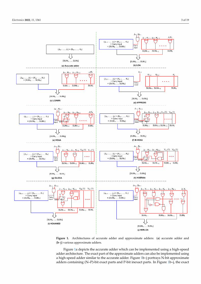
Figure 1 portrays block-level schematics of the accurate adder and various approximateadders which are considered for implementing image compression. JN−1 to J0 representthe most significant bit to the least significant bit of an N-bit adder input, and KN−1. to K0represent the most significant bit to the least significant bit of the other adder input.
Electronics 2022, 11, 1361 3 of 19
Electronics 2022, 11, x FOR PEER REVIEW 3 of 20
represent the most significant bit to the least significant bit of an N-bit adder input, and
KN−1to K0 represent the most significant bit to the least significant bit of the other adder
input.
Figure 1. Architectures of accurate adder and approximate adders: (a) accurate adder and (b–j)
various approximate adders.
Figure 1. Architectures of accurate adder and approximate adders: (a) accurate adder and(b–j) various approximate adders.
Figure 1a depicts the accurate adder which can be implemented using a high-speedadder architecture. The exact part of the approximate adders can also be implemented usinga high-speed adder similar to the accurate adder. Figure 1b–j portrays N-bit approximateadders containing (N–P)-bit exact parts and P-bit inexact parts. In Figure 1b–j, the exact
Electronics 2022, 11, 1361 4 of 19
part is depicted in blue and comprises input bits ranging from JN−1 to JP and KN−1 to KP.The inexact part is depicted in red, which comprises input bits ranging from JP−1 to J0 andKP−1 to K0. The exact part of an approximate adder may or may not receive a carry inputfrom the inexact part depending upon its architecture.
In this paper, the accurate adder shown in Figure 1a and the exact part of the ap-proximate adders shown in Figure 1b–j are realized using a high-speed carry look-aheadadder (CLA) [22] for an ASIC-type implementation, and using ahigh-speed native accurateFPGA adder for an FPGA-based implementation. Since the exact parts of the approximateadders are identical, the following discussion is only concerned with the inexact parts ofthe approximate adders shown in Figure 1.
Reference [23] presented a lower part OR approximate adder called LOA, shown inFigure 1b, where sum bits SUMP−1 to SUM0 are calculated by performing a bitwise-ORbetween the corresponding input bits. LOA performs bitwise AND between JP−1 and KP−1of the inexact part to generate and provide a carry input to the exact part. Figure 1c showsanother approximate adder [24], referred to as LOAWA in [25], which is similar to LOA butis different in that no carry input is provided from the inexact part to the exact part.
Reference [26] presented an approximate adder called APPROX5 in [25], which isshown in Figure 1d, which forwards input bits KP−1. up to K0 as the respective sum bitsSUMP−1 to SUM0 of the inexact part and supplies the input bit JP−1 as the carry input tothe exact part. Input bits JP−2. up to J0. are not used and discarded in APPROX5.
The approximate adder shown in Figure 1e viz. HEAA [27], as it is called in [25],performs bitwise-AND between JP−1. and KP−1; if this results in binary 0, no carry input isprovided to the exact part and the inexact part of HEAA would be the same as LOA andLOAWA; however, if binary 1 is the result, HEAA differs in that the sum bit SUMP−1. is setto 0, while the logic of the remaining sum bits from SUMP−2 to SUM0 would be the sameas LOA and LOAWA. Figure 1f depicts M-HEAA [28] that is derived from an architecturalmodification of HEAA in which the (P–2) least significant sum bits of the inexact part areset to 1 while the rest of the logic of M-HEAA is the same as HEAA.
Approximate adder OLOCA [29], shown in Figure 1g, is obtained based on a modi-fication of LOA in that the (P–2) least significant sum bits of the inexact part are set to 1while the rest of the logic of OLOCA is the same as LOA.
Approximate adder HOERAA [25] is shown in Figure 1h, which features a carry inputprovided from the inexact part to the exact part that is the same as LOA, HEAA, M-HEAA,and OLOCA. As with M-HEAA and OLOCA, the (P–2) least significant sum bits of theinexact part are set to one in HOERAA. Sum bit SUMP−2 is calculated by performingbitwise-OR between JP−2 and KP−2. Sum bit SUMP−1 is produced as the output of a 2:1multiplexer (MUX), whose select input is the carry input given to the exact part. If theselect input is 0, the logical-OR of JP−1 and KP−1 is produced as SUMP−1, and if the selectinput is 1, the logical-AND of JP−2 and KP−2 is produced as SUMP−1.
Approximate adder HOAANED [30] is shown in Figure 1i that also features a carryinput supplied from the inexact part to the exact part similar to LOA, HEAA, M-HEAA,OLOCA, and HOERAA. The logic of SUMP−2 up to SUM0 of HOAANED is the same asM-HEAA, OLOCA, and HOERAA. As with HEAA, M-HEAA, and HOERAA, HOAANEDalso has a MUX in the logic corresponding to SUMP−1, whose select input is the carry inputgiven to the exact part. If the MUX select input is 0, JP−1 and KP−1 are OR-ed and JP−2 andKP−2 are AND-ed, and these two are finally OR-ed to produce SUMP−1. On the contrary, ifthe MUX select input is 1, the logical AND of JP−2 and KP−2 is produced as SUMP−1.
Another approximate adder called HERLOA, presented in Reference [31], is shown inFigure 1j, which features a unique logic circuit used to produce the sum bits of the inexactpart. However, the carry input supplied from the inexact part to the exact part has the samelogic as LOA, HEAA, M-HEAA, OLOCA, HOERAA, and HOAANED.
In the next section, the performance of the accurate adder is compared with theperformance of the approximate adders for digital image compression.
Electronics 2022, 11, 1361 5 of 19
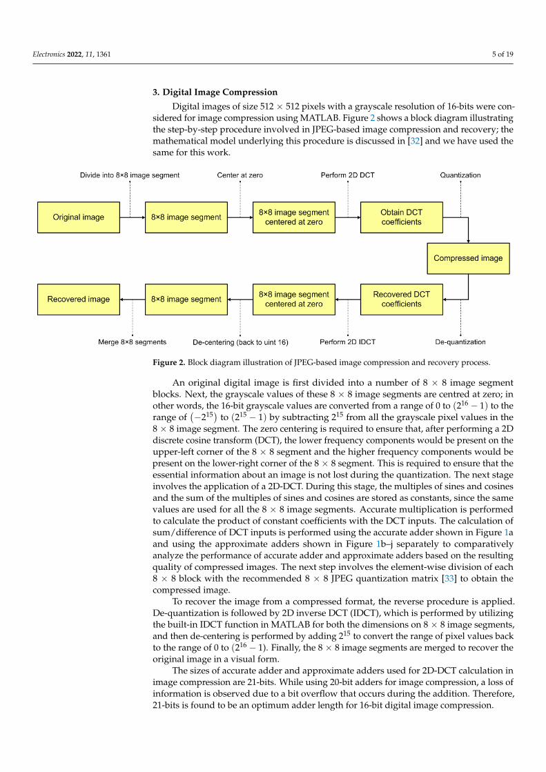
3. Digital Image Compression
Digital images of size 512 × 512 pixels with a grayscale resolution of 16-bits were con-sidered for image compression using MATLAB. Figure 2 shows a block diagram illustratingthe step-by-step procedure involved in JPEG-based image compression and recovery; themathematical model underlying this procedure is discussed in [32] and we have used thesame for this work.
Electronics 2022, 11, x FOR PEER REVIEW 5 of 20
Another approximate adder called HERLOA, presented in Reference [31], is shown
in Figure 1j, which features a unique logic circuit used to produce the sum bits of the
inexact part. However, the carry input supplied from the inexact part to the exact part has
the same logic as LOA, HEAA, M-HEAA, OLOCA, HOERAA, and HOAANED.
In the next section, the performance of the accurate adder is compared with the per-
formance of the approximate adders for digital image compression.
3. Digital Image Compression
Digital images of size 512 × 512 pixels with a grayscale resolution of 16-bits were
considered for image compression using MATLAB. Figure 2 shows a block diagram illus-
trating the step-by-step procedure involved in JPEG-based image compression and recov-
ery; the mathematical model underlying this procedure is discussed in [32] and we have
used the same for this work.
An original digital image is first divided into a number of 8 × 8 image segment blocks.
Next, the grayscale values of these 8 × 8 image segments are centred at zero; in other
words, the 16-bit grayscale values are converted from a range of 0 to (216 − 1) to the
range of (−215) to (215 − 1) by subtracting 215 from all the grayscale pixel values in the
8 × 8 image segment. The zero centering is required to ensure that, after performing a 2D
discrete cosine transform (DCT), the lower frequency components would be present on
the upper-left corner of the 8 × 8 segment and the higher frequency components would be
present on the lower-right corner of the 8 × 8 segment. This is required to ensure that the
essential information about an image is not lost during the quantization. The next stage
involves the application of a 2D-DCT. During this stage, the multiples of sines and cosines
and the sum of the multiples of sines and cosines are stored as constants, since the same
values are used for all the 8 × 8 image segments. Accurate multiplication is performed to
calculate the product of constant coefficients with the DCT inputs. The calculation of
sum/difference of DCT inputs is performed using the accurate adder shown in Figure 1a
and using the approximate adders shown in Figure 1b–j separately to comparatively ana-
lyze the performance of accurate adder and approximate adders based on the resulting
quality of compressed images. The next step involves the element-wise division of each 8
× 8 block with the recommended 8 × 8 JPEG quantization matrix [33] to obtain the com-
pressed image.
Figure 2. Block diagram illustration of JPEG-based image compression and recovery process.
To recover the image from a compressed format, the reverse procedure is applied.
De-quantization is followed by 2D inverse DCT (IDCT), which is performed by utilizing
the built-in IDCT function in MATLAB for both the dimensions on 8 × 8 image segments,
and then de-centering is performed by adding 215 to convert the range of pixel values
Figure 2. Block diagram illustration of JPEG-based image compression and recovery process.
An original digital image is first divided into a number of 8 × 8 image segmentblocks. Next, the grayscale values of these 8 × 8 image segments are centred at zero; inother words, the 16-bit grayscale values are converted from a range of 0 to (216 − 1) to therange of
(−215) to (215 − 1) by subtracting 215 from all the grayscale pixel values in the
8 × 8 image segment. The zero centering is required to ensure that, after performing a 2Ddiscrete cosine transform (DCT), the lower frequency components would be present on theupper-left corner of the 8 × 8 segment and the higher frequency components would bepresent on the lower-right corner of the 8 × 8 segment. This is required to ensure that theessential information about an image is not lost during the quantization. The next stageinvolves the application of a 2D-DCT. During this stage, the multiples of sines and cosinesand the sum of the multiples of sines and cosines are stored as constants, since the samevalues are used for all the 8 × 8 image segments. Accurate multiplication is performedto calculate the product of constant coefficients with the DCT inputs. The calculation ofsum/difference of DCT inputs is performed using the accurate adder shown in Figure 1aand using the approximate adders shown in Figure 1b–j separately to comparativelyanalyze the performance of accurate adder and approximate adders based on the resultingquality of compressed images. The next step involves the element-wise division of each8 × 8 block with the recommended 8 × 8 JPEG quantization matrix [33] to obtain thecompressed image.
To recover the image from a compressed format, the reverse procedure is applied.De-quantization is followed by 2D inverse DCT (IDCT), which is performed by utilizingthe built-in IDCT function in MATLAB for both the dimensions on 8 × 8 image segments,and then de-centering is performed by adding 215 to convert the range of pixel values backto the range of 0 to (216 − 1). Finally, the 8 × 8 image segments are merged to recover theoriginal image in a visual form.
The sizes of accurate adder and approximate adders used for 2D-DCT calculation inimage compression are 21-bits. While using 20-bit adders for image compression, a loss ofinformation is observed due to a bit overflow that occurs during the addition. Therefore,21-bits is found to be an optimum adder length for 16-bit digital image compression.
Electronics 2022, 11, 1361 6 of 19
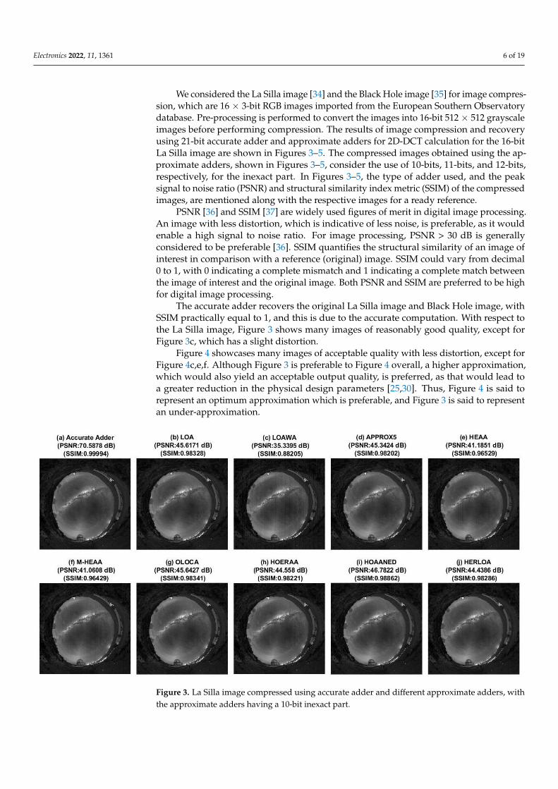
We considered the La Silla image [34] and the Black Hole image [35] for image compres-sion, which are 16 × 3-bit RGB images imported from the European Southern Observatorydatabase. Pre-processing is performed to convert the images into 16-bit 512 × 512 grayscaleimages before performing compression. The results of image compression and recoveryusing 21-bit accurate adder and approximate adders for 2D-DCT calculation for the 16-bitLa Silla image are shown in Figures 3–5. The compressed images obtained using the ap-proximate adders, shown in Figures 3–5, consider the use of 10-bits, 11-bits, and 12-bits,respectively, for the inexact part. In Figures 3–5, the type of adder used, and the peaksignal to noise ratio (PSNR) and structural similarity index metric (SSIM) of the compressedimages, are mentioned along with the respective images for a ready reference.
PSNR [36] and SSIM [37] are widely used figures of merit in digital image processing.An image with less distortion, which is indicative of less noise, is preferable, as it wouldenable a high signal to noise ratio. For image processing, PSNR > 30 dB is generallyconsidered to be preferable [36]. SSIM quantifies the structural similarity of an image ofinterest in comparison with a reference (original) image. SSIM could vary from decimal0 to 1, with 0 indicating a complete mismatch and 1 indicating a complete match betweenthe image of interest and the original image. Both PSNR and SSIM are preferred to be highfor digital image processing.
The accurate adder recovers the original La Silla image and Black Hole image, withSSIM practically equal to 1, and this is due to the accurate computation. With respect tothe La Silla image, Figure 3 shows many images of reasonably good quality, except forFigure 3c, which has a slight distortion.
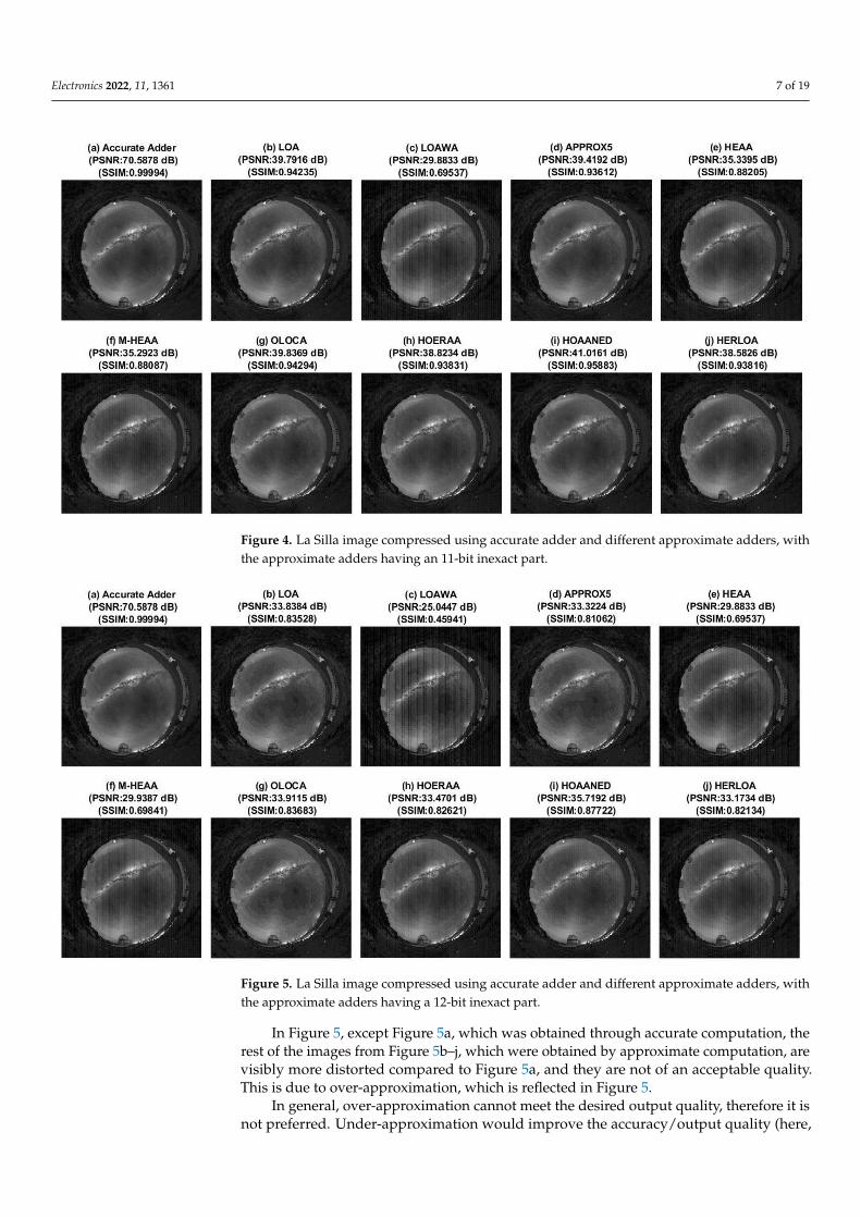
Figure 4 showcases many images of acceptable quality with less distortion, except forFigure 4c,e,f. Although Figure 3 is preferable to Figure 4 overall, a higher approximation,which would also yield an acceptable output quality, is preferred, as that would lead toa greater reduction in the physical design parameters [25,30]. Thus, Figure 4 is said torepresent an optimum approximation which is preferable, and Figure 3 is said to representan under-approximation.
Electronics 2022, 11, x FOR PEER REVIEW 6 of 20
back to the range of 0 to (216 − 1). Finally, the 8 × 8 image segments are merged to recover
the original image in a visual form.
The sizes of accurate adder and approximate adders used for 2D-DCT calculation in
image compression are 21-bits. While using 20-bit adders for image compression, a loss of
information is observed due to a bit overflow that occurs during the addition. Therefore,
21-bits is found to be an optimum adder length for 16-bit digital image compression.
We considered the La Silla image [34] and the Black Hole image [35] for image com-
pression, which are 16 × 3-bit RGB images imported from the European Southern Obser-
vatory database. Pre-processing is performed to convert the images into 16-bit 512 × 512
grayscale images before performing compression. The results of image compression and
recovery using 21-bit accurate adder and approximate adders for 2D-DCT calculation for
the 16-bit La Silla image are shown in Figures 3–5. The compressed images obtained using
the approximate adders, shown in Figures 3–5, consider the use of 10-bits, 11-bits, and 12-
bits, respectively, for the inexact part. In Figures 3–5, the type of adder used, and the peak
signal to noise ratio (PSNR) and structural similarity index metric (SSIM) of the com-
pressed images, are mentioned along with the respective images for a ready reference.
PSNR [36] and SSIM [37] are widely used figures of merit in digital image processing.
An image with less distortion, which is indicative of less noise, is preferable, as it would
enable a high signal to noise ratio. For image processing, PSNR > 30 dB is generally con-
sidered to be preferable [36]. SSIM quantifies the structural similarity of an image of in-
terest in comparison with a reference (original) image. SSIM could vary from decimal 0 to
1, with 0 indicating a complete mismatch and 1 indicating a complete match between the
image of interest and the original image. Both PSNR and SSIM are preferred to be high
for digital image processing.
The accurate adder recovers the original La Silla image and Black Hole image, with
SSIM practically equal to 1, and this is due to the accurate computation. With respect to
the La Silla image, Figure 3 shows many images of reasonably good quality, except for
Figure 3c, which has a slight distortion.
Figure 3. La Silla image compressed using accurate adder and different approximate adders, with
the approximate adders having a 10-bit inexact part. Figure 3. La Silla image compressed using accurate adder and different approximate adders, withthe approximate adders having a 10-bit inexact part.
Electronics 2022, 11, 1361 7 of 19
Electronics 2022, 11, x FOR PEER REVIEW 7 of 20
Figure 4 showcases many images of acceptable quality with less distortion, except for
Figure 4c,e,f. Although Figure 3 is preferable to Figure 4 overall, a higher approximation,
which would also yield an acceptable output quality, is preferred, as that would lead to a
greater reduction in the physical design parameters [25,30]. Thus, Figure 4 is said to rep-
resent an optimum approximation which is preferable, and Figure 3 is said to represent
an under-approximation.
Figure 4. La Silla image compressed using accurate adder and different approximate adders, with
the approximate adders having an 11-bit inexact part.
Figure 5. La Silla image compressed using accurate adder and different approximate adders, with
the approximate adders having a 12-bit inexact part.
Figure 4. La Silla image compressed using accurate adder and different approximate adders, withthe approximate adders having an 11-bit inexact part.
Electronics 2022, 11, x FOR PEER REVIEW 7 of 20
Figure 4 showcases many images of acceptable quality with less distortion, except for
Figure 4c,e,f. Although Figure 3 is preferable to Figure 4 overall, a higher approximation,
which would also yield an acceptable output quality, is preferred, as that would lead to a
greater reduction in the physical design parameters [25,30]. Thus, Figure 4 is said to rep-
resent an optimum approximation which is preferable, and Figure 3 is said to represent
an under-approximation.
Figure 4. La Silla image compressed using accurate adder and different approximate adders, with
the approximate adders having an 11-bit inexact part.
Figure 5. La Silla image compressed using accurate adder and different approximate adders, with
the approximate adders having a 12-bit inexact part. Figure 5. La Silla image compressed using accurate adder and different approximate adders, withthe approximate adders having a 12-bit inexact part.
In Figure 5, except Figure 5a, which was obtained through accurate computation, therest of the images from Figure 5b–j, which were obtained by approximate computation, arevisibly more distorted compared to Figure 5a, and they are not of an acceptable quality.This is due to over-approximation, which is reflected in Figure 5.
In general, over-approximation cannot meet the desired output quality, therefore it isnot preferred. Under-approximation would improve the accuracy/output quality (here,
Electronics 2022, 11, 1361 8 of 19
image quality), but would reduce the savings achievable in the design parameters, thereforeit may not be preferable. Hence, an optimum approximation that would guarantee anacceptable accuracy while enabling optimum savings in the design parameters is preferable.
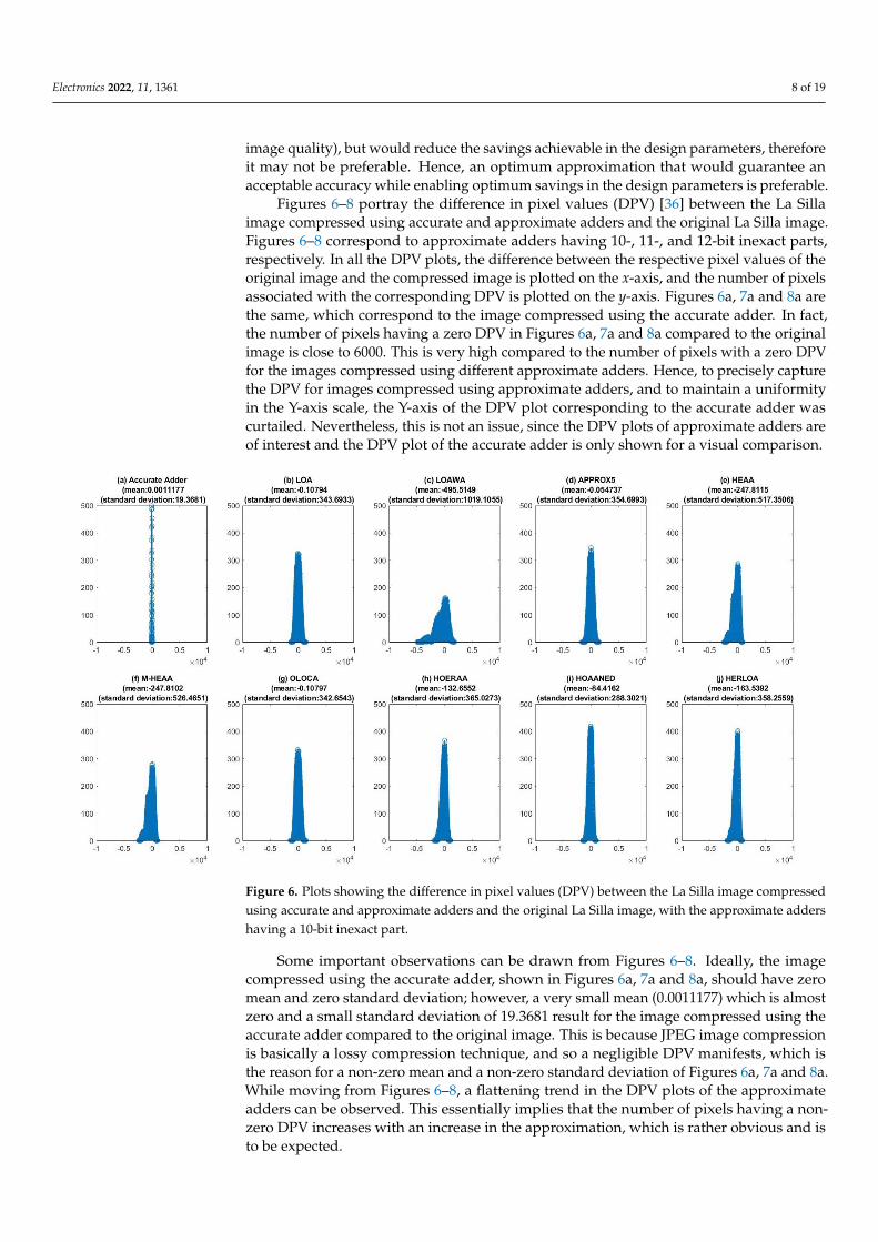
Figures 6–8 portray the difference in pixel values (DPV) [36] between the La Sillaimage compressed using accurate and approximate adders and the original La Silla image.Figures 6–8 correspond to approximate adders having 10-, 11-, and 12-bit inexact parts,respectively. In all the DPV plots, the difference between the respective pixel values of theoriginal image and the compressed image is plotted on the x-axis, and the number of pixelsassociated with the corresponding DPV is plotted on the y-axis. Figures 6a, 7a and 8a arethe same, which correspond to the image compressed using the accurate adder. In fact,the number of pixels having a zero DPV in Figures 6a, 7a and 8a compared to the originalimage is close to 6000. This is very high compared to the number of pixels with a zero DPVfor the images compressed using different approximate adders. Hence, to precisely capturethe DPV for images compressed using approximate adders, and to maintain a uniformityin the Y-axis scale, the Y-axis of the DPV plot corresponding to the accurate adder wascurtailed. Nevertheless, this is not an issue, since the DPV plots of approximate adders areof interest and the DPV plot of the accurate adder is only shown for a visual comparison.
Electronics 2022, 11, x FOR PEER REVIEW 8 of 20
In Figure 5, except Figure 5a, which was obtained through accurate computation, the
rest of the images from Figure 5b–j, which were obtained by approximate computation,
are visibly more distorted compared to Figure 5a, and they are not of an acceptable qual-
ity. This is due to over-approximation, which is reflected in Figure 5.
In general, over-approximation cannot meet the desired output quality, therefore it
is not preferred. Under-approximation would improve the accuracy/output quality (here,
image quality), but would reduce the savings achievable in the design parameters, there-
fore it may not be preferable. Hence, an optimum approximation that would guarantee
an acceptable accuracy while enabling optimum savings in the design parameters is pref-
erable.
Figures 6–8 portray the difference in pixel values (DPV) [36] between the La Silla
image compressed using accurate and approximate adders and the original La Silla image.
Figures 6–8 correspond to approximate adders having 10-, 11-, and 12-bit inexact parts,
respectively. In all the DPV plots, the difference between the respective pixel values of the
original image and the compressed image is plotted on the X-axis, and the number of pix-
els associated with the corresponding DPV is plotted on the Y-axis. Figures 6a, 7a and 8a
are the same, which correspond to the image compressed using the accurate adder. In fact,
the number of pixels having a zero DPV in Figures 6a, 7a and 8a compared to the original
image is close to 6000. This is very high compared to the number of pixels with a zero
DPV for the images compressed using different approximate adders. Hence, to precisely
capture the DPV for images compressed using approximate adders, and to maintain a
uniformity in the Y-axis scale, the Y-axis of the DPV plot corresponding to the accurate
adder was curtailed. Nevertheless, this is not an issue, since the DPV plots of approximate
adders are of interest and the DPV plot of the accurate adder is only shown for a visual
comparison.
Figure 6. Plots showing the difference in pixel values (DPV) between the La Silla image com-
pressed using accurate and approximate adders and the original La Silla image, with the approxi-
mate adders having a 10-bit inexact part.
Figure 6. Plots showing the difference in pixel values (DPV) between the La Silla image compressedusing accurate and approximate adders and the original La Silla image, with the approximate addershaving a 10-bit inexact part.
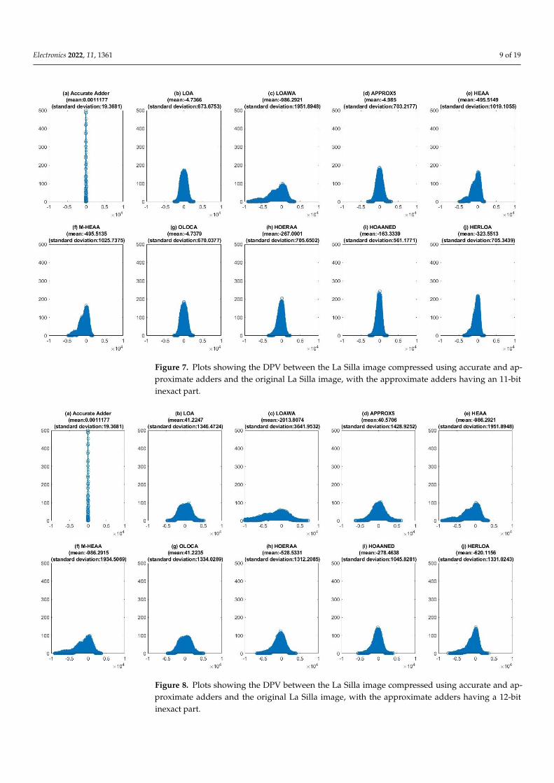
Some important observations can be drawn from Figures 6–8. Ideally, the imagecompressed using the accurate adder, shown in Figures 6a, 7a and 8a, should have zeromean and zero standard deviation; however, a very small mean (0.0011177) which is almostzero and a small standard deviation of 19.3681 result for the image compressed using theaccurate adder compared to the original image. This is because JPEG image compressionis basically a lossy compression technique, and so a negligible DPV manifests, which isthe reason for a non-zero mean and a non-zero standard deviation of Figures 6a, 7a and 8a.While moving from Figures 6–8, a flattening trend in the DPV plots of the approximateadders can be observed. This essentially implies that the number of pixels having a non-zero DPV increases with an increase in the approximation, which is rather obvious and isto be expected.
Electronics 2022, 11, 1361 9 of 19Electronics 2022, 11, x FOR PEER REVIEW 9 of 20
Figure 7. Plots showing the DPV between the La Silla image compressed using accurate and ap-
proximate adders and the original La Silla image, with the approximate adders having an 11-bit
inexact part.
Figure 8. Plots showing the DPV between the La Silla image compressed using accurate and ap-
proximate adders and the original La Silla image, with the approximate adders having a 12-bit
inexact part.
Figure 7. Plots showing the DPV between the La Silla image compressed using accurate and ap-proximate adders and the original La Silla image, with the approximate adders having an 11-bitinexact part.
Electronics 2022, 11, x FOR PEER REVIEW 9 of 20
Figure 7. Plots showing the DPV between the La Silla image compressed using accurate and ap-
proximate adders and the original La Silla image, with the approximate adders having an 11-bit
inexact part.
Figure 8. Plots showing the DPV between the La Silla image compressed using accurate and ap-
proximate adders and the original La Silla image, with the approximate adders having a 12-bit
inexact part.
Figure 8. Plots showing the DPV between the La Silla image compressed using accurate and ap-proximate adders and the original La Silla image, with the approximate adders having a 12-bitinexact part.
Electronics 2022, 11, 1361 10 of 19
Figures 6–8 uniformly show that the number of pixels having a zero DPV is greaterfor the images compressed using HOAANED (i.e., Figures 6i, 7i and 8i) compared to theimages compressed using other approximate adders. Though the DPV plots correspondingto the images compressed using HERLOA (Figures 6j, 7j and 8j) have nearly the samenumber of pixels with a zero DPV as HOAANED, HOAANED consistently reports lowermean and standard deviation values compared to HERLOA for the different approximationscenarios. Hence, HOAANED is preferable to the other approximate adders, which is inagreement with the inference derived from Figures 3–5.
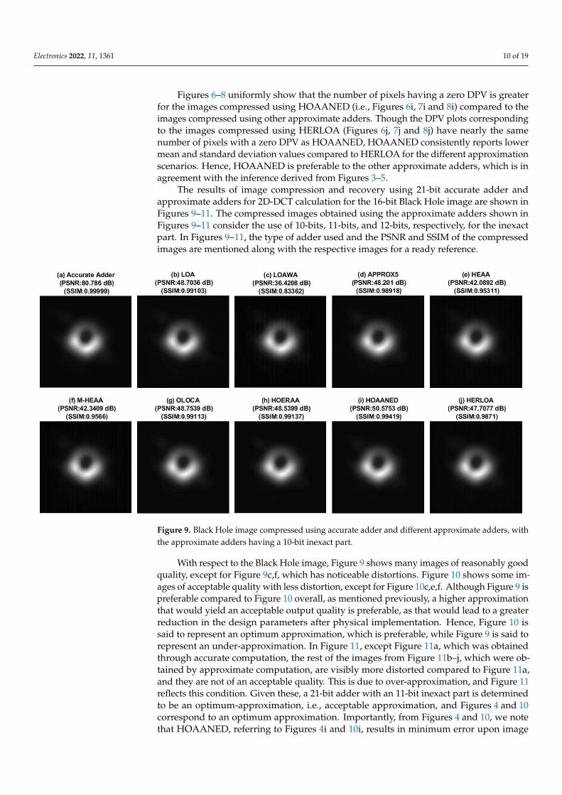
The results of image compression and recovery using 21-bit accurate adder andapproximate adders for 2D-DCT calculation for the 16-bit Black Hole image are shown inFigures 9–11. The compressed images obtained using the approximate adders shown inFigures 9–11 consider the use of 10-bits, 11-bits, and 12-bits, respectively, for the inexactpart. In Figures 9–11, the type of adder used and the PSNR and SSIM of the compressedimages are mentioned along with the respective images for a ready reference.
Electronics 2022, 11, x FOR PEER REVIEW 11 of 20
Figure 9. Black Hole image compressed using accurate adder and different approximate adders,
with the approximate adders having a 10-bit inexact part.
Figure 10. Black Hole image compressed using accurate adder and different approximate adders,
with the approximate adders having an 11-bit inexact part.
Figure 9. Black Hole image compressed using accurate adder and different approximate adders, withthe approximate adders having a 10-bit inexact part.
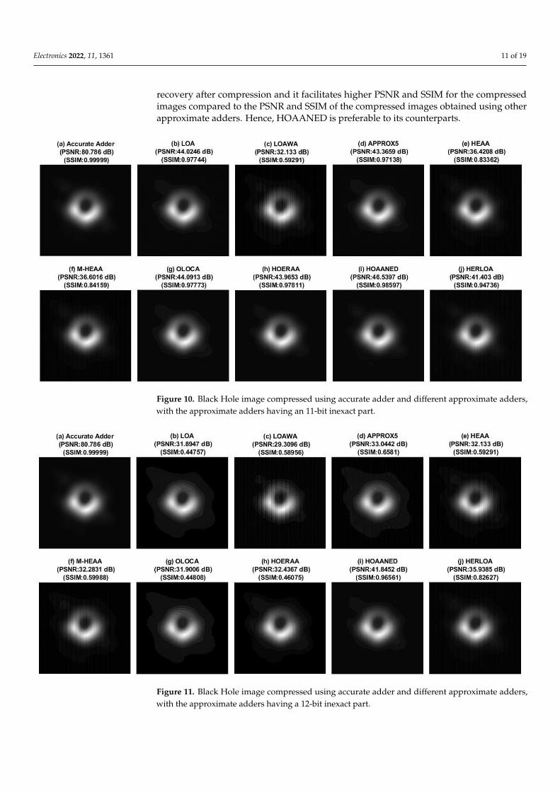
With respect to the Black Hole image, Figure 9 shows many images of reasonably goodquality, except for Figure 9c,f, which has noticeable distortions. Figure 10 shows some im-ages of acceptable quality with less distortion, except for Figure 10c,e,f. Although Figure 9 ispreferable compared to Figure 10 overall, as mentioned previously, a higher approximationthat would yield an acceptable output quality is preferable, as that would lead to a greaterreduction in the design parameters after physical implementation. Hence, Figure 10 issaid to represent an optimum approximation, which is preferable, while Figure 9 is said torepresent an under-approximation. In Figure 11, except Figure 11a, which was obtainedthrough accurate computation, the rest of the images from Figure 11b–j, which were ob-tained by approximate computation, are visibly more distorted compared to Figure 11a,and they are not of an acceptable quality. This is due to over-approximation, and Figure 11reflects this condition. Given these, a 21-bit adder with an 11-bit inexact part is determinedto be an optimum-approximation, i.e., acceptable approximation, and Figures 4 and 10correspond to an optimum approximation. Importantly, from Figures 4 and 10, we notethat HOAANED, referring to Figures 4i and 10i, results in minimum error upon image
Electronics 2022, 11, 1361 11 of 19
recovery after compression and it facilitates higher PSNR and SSIM for the compressedimages compared to the PSNR and SSIM of the compressed images obtained using otherapproximate adders. Hence, HOAANED is preferable to its counterparts.
Electronics 2022, 11, x FOR PEER REVIEW 11 of 20
Figure 9. Black Hole image compressed using accurate adder and different approximate adders,
with the approximate adders having a 10-bit inexact part.
Figure 10. Black Hole image compressed using accurate adder and different approximate adders,
with the approximate adders having an 11-bit inexact part. Figure 10. Black Hole image compressed using accurate adder and different approximate adders,with the approximate adders having an 11-bit inexact part.
Electronics 2022, 11, x FOR PEER REVIEW 12 of 20
Figure 11. Black Hole image compressed using accurate adder and different approximate adders,
with the approximate adders having a 12-bit inexact part.
Figures 12–14 portray the DPV plots of the compressed Black Hole image using ac-
curate and approximate adders in comparison with the original Black Hole image. Figures
12–14 correspond to approximate adders having 10-, 11-, and 12-bit inexact parts respec-
tively. Figures 12a, 13a and 14a are the same, which correspond to the image compressed
using the accurate adder, and a non-zero mean and a non-zero standard deviation are
associated with them due to the lossy JPEG image compression. In fact, the number of
pixels that have a zero DPV in Figures 12a, 13a and 14a compared to the original image is
found to be close to 20,000. This is much higher compared to the number of pixels that
have a zero DPV for the images compressed using different approximate adders. Hence,
to precisely capture the DPV for images compressed using various approximate adders,
and to maintain a uniformity in the Y-axis scale, the Y-axis of the DPV plot corresponding
to the accurate adder has been curtailed. Nevertheless, this is not an issue, since the DPV
plots of approximate adders are of interest and the DPV plot of the accurate adder is only
shown for a visual comparison. While moving from Figures 12–14, a flattening trend in
the DPV plots of the approximate adders can be observed, as observed in Figures 6–8,
which implies that the number of pixels that have a non-zero DPV increases with an in-
crease in the approximation.
Figures 12–14 also uniformly show that the number of pixels that have a zero DPV is
greater for the images compressed using HOAANED (i.e., Figures 12i, 13i and 14i) com-
pared to the images compressed using other approximate adders. Hence, HOAANED is
preferable to the other approximate adders for image compression, which is in agreement
with the inference derived from Figures 9–11.
Figure 11. Black Hole image compressed using accurate adder and different approximate adders,with the approximate adders having a 12-bit inexact part.
Electronics 2022, 11, 1361 12 of 19
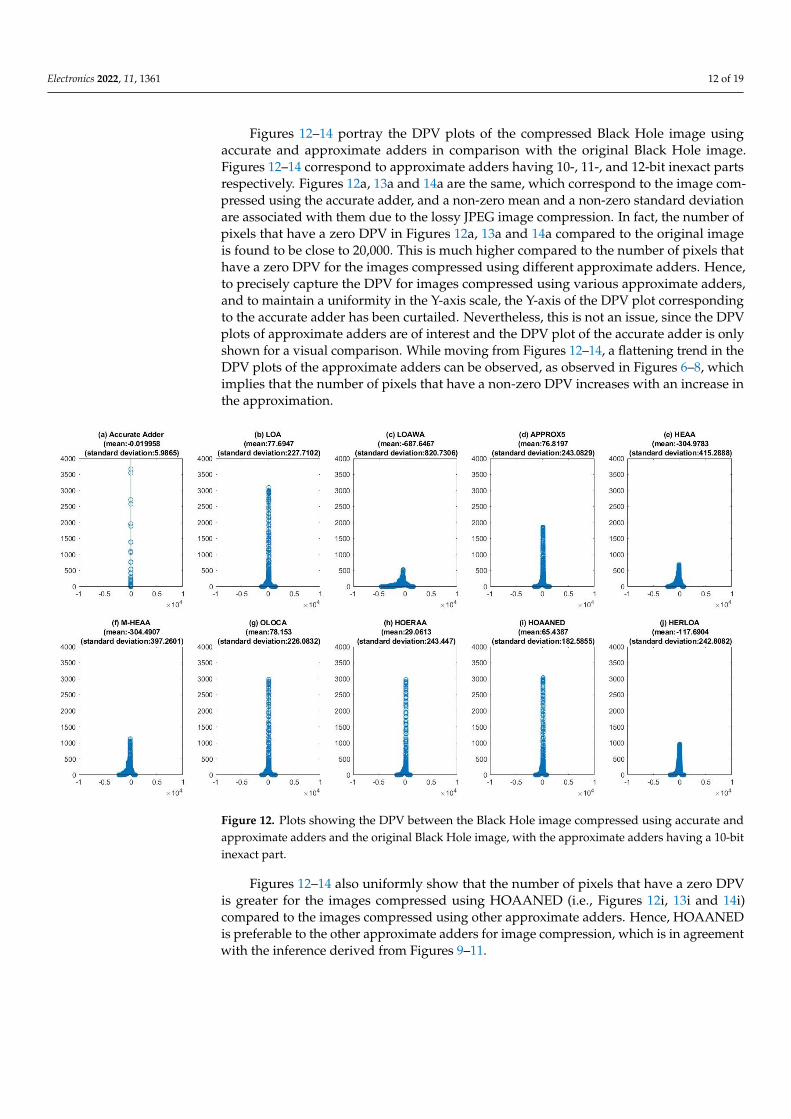
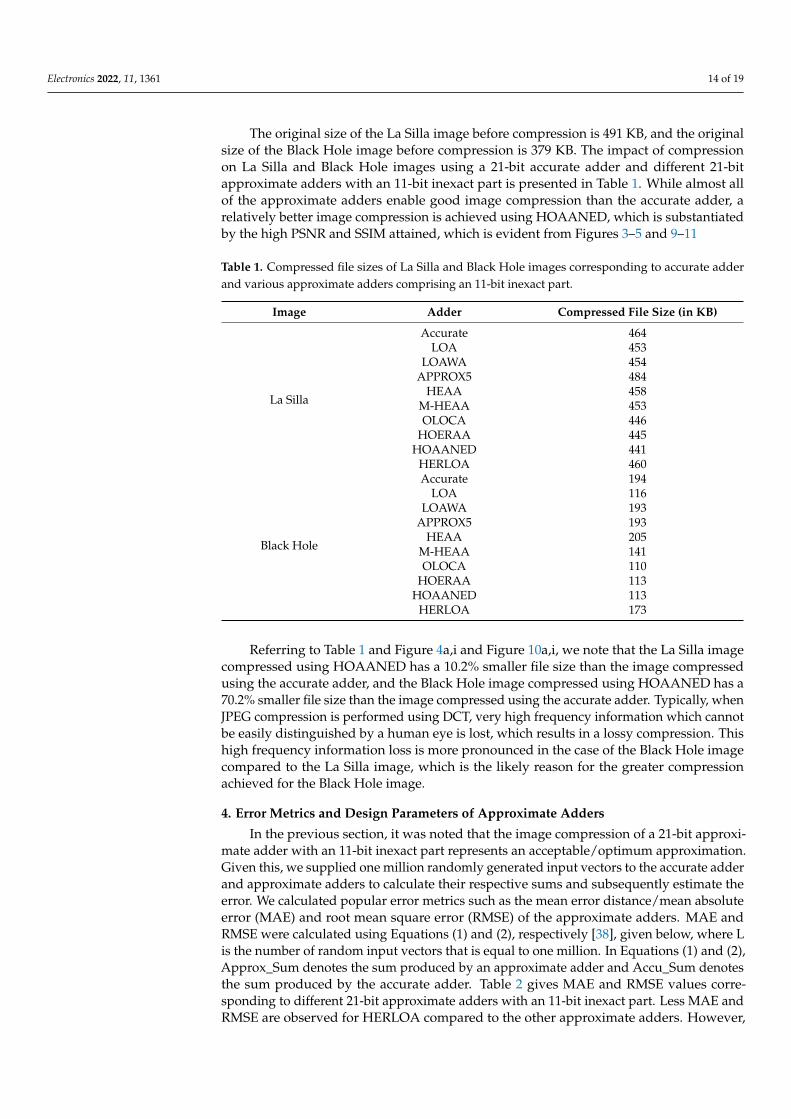
Figures 12–14 portray the DPV plots of the compressed Black Hole image usingaccurate and approximate adders in comparison with the original Black Hole image.Figures 12–14 correspond to approximate adders having 10-, 11-, and 12-bit inexact partsrespectively. Figures 12a, 13a and 14a are the same, which correspond to the image com-pressed using the accurate adder, and a non-zero mean and a non-zero standard deviationare associated with them due to the lossy JPEG image compression. In fact, the number ofpixels that have a zero DPV in Figures 12a, 13a and 14a compared to the original imageis found to be close to 20,000. This is much higher compared to the number of pixels thathave a zero DPV for the images compressed using different approximate adders. Hence,to precisely capture the DPV for images compressed using various approximate adders,and to maintain a uniformity in the Y-axis scale, the Y-axis of the DPV plot correspondingto the accurate adder has been curtailed. Nevertheless, this is not an issue, since the DPVplots of approximate adders are of interest and the DPV plot of the accurate adder is onlyshown for a visual comparison. While moving from Figures 12–14, a flattening trend in theDPV plots of the approximate adders can be observed, as observed in Figures 6–8, whichimplies that the number of pixels that have a non-zero DPV increases with an increase inthe approximation.
Electronics 2022, 11, x FOR PEER REVIEW 13 of 20
Figure 12. Plots showing the DPV between the Black Hole image compressed using accurate and
approximate adders and the original Black Hole image, with the approximate adders having a 10-
bit inexact part.
Figure 13. Plots showing the DPV between the Black Hole image compressed using accurate and
approximate adders and the original Black Hole image, with the approximate adders having an
11-bit inexact part.
Figure 12. Plots showing the DPV between the Black Hole image compressed using accurate andapproximate adders and the original Black Hole image, with the approximate adders having a 10-bitinexact part.
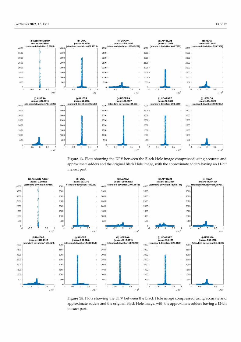
Figures 12–14 also uniformly show that the number of pixels that have a zero DPVis greater for the images compressed using HOAANED (i.e., Figures 12i, 13i and 14i)compared to the images compressed using other approximate adders. Hence, HOAANEDis preferable to the other approximate adders for image compression, which is in agreementwith the inference derived from Figures 9–11.
Electronics 2022, 11, 1361 13 of 19
Electronics 2022, 11, x FOR PEER REVIEW 13 of 20
Figure 12. Plots showing the DPV between the Black Hole image compressed using accurate and
approximate adders and the original Black Hole image, with the approximate adders having a 10-
bit inexact part.
Figure 13. Plots showing the DPV between the Black Hole image compressed using accurate and
approximate adders and the original Black Hole image, with the approximate adders having an
11-bit inexact part.
Figure 13. Plots showing the DPV between the Black Hole image compressed using accurate andapproximate adders and the original Black Hole image, with the approximate adders having an 11-bitinexact part.
Electronics 2022, 11, x FOR PEER REVIEW 14 of 20
Figure 14. Plots showing the DPV between the Black Hole image compressed using accurate and
approximate adders and the original Black Hole image, with the approximate adders having a 12-
bit inexact part.
The original size of the La Silla image before compression is 491 KB, and the original
size of the Black Hole image before compression is 379 KB. The impact of compression on
La Silla and Black Hole images using a 21-bit accurate adder and different 21-bit approx-
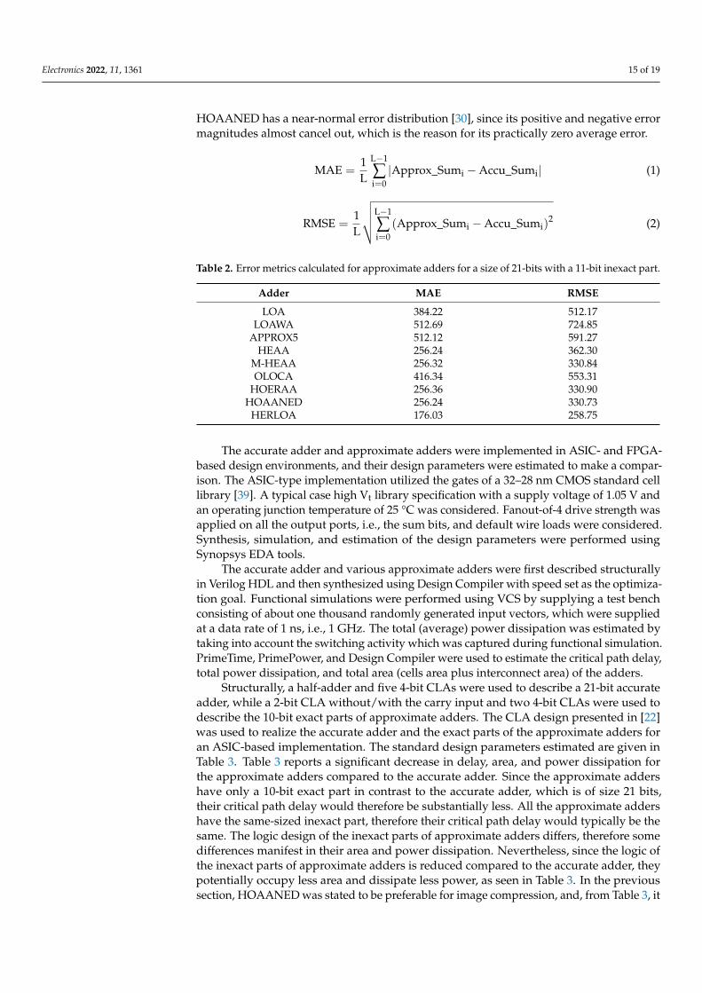
imate adders with an 11-bit inexact part is presented in Table 1. While almost all of the
approximate adders enable good image compression than the accurate adder, a relatively
better image compression is achieved using HOAANED, which is substantiated by the
high PSNR and SSIM attained, which is evident from Figures 3–5 and 9–11.
Referring to Table 1 and Figures 4a,i and 10a,i, we note that the La Silla image com-
pressed using HOAANED has a 10.2% smaller file size than the image compressed using
the accurate adder, and the Black Hole image compressed using HOAANED has a 70.2%
smaller file size than the image compressed using the accurate adder. Typically, when
JPEG compression is performed using DCT, very high frequency information which can-
not be easily distinguished by a human eye is lost, which results in a lossy compression.
This high frequency information loss is more pronounced in the case of the Black Hole
image compared to the La Silla image, which is the likely reason for the greater compres-
sion achieved for the Black Hole image.
Table 1. Compressed file sizes of La Silla and Black Hole images corresponding to accurate adder
and various approximate adders comprising an 11-bit inexact part.
Image Adder Compressed File Size (in KB)
La Silla
Accurate 464
LOA 453
LOAWA 454
APPROX5 484
HEAA 458
M-HEAA 453
Figure 14. Plots showing the DPV between the Black Hole image compressed using accurate andapproximate adders and the original Black Hole image, with the approximate adders having a 12-bitinexact part.
Electronics 2022, 11, 1361 14 of 19
The original size of the La Silla image before compression is 491 KB, and the originalsize of the Black Hole image before compression is 379 KB. The impact of compressionon La Silla and Black Hole images using a 21-bit accurate adder and different 21-bitapproximate adders with an 11-bit inexact part is presented in Table 1. While almost allof the approximate adders enable good image compression than the accurate adder, arelatively better image compression is achieved using HOAANED, which is substantiatedby the high PSNR and SSIM attained, which is evident from Figures 3–5 and 9–11
Table 1. Compressed file sizes of La Silla and Black Hole images corresponding to accurate adderand various approximate adders comprising an 11-bit inexact part.
Image Adder Compressed File Size (in KB)
La Silla
Accurate 464LOA 453
LOAWA 454APPROX5 484
HEAA 458M-HEAA 453OLOCA 446
HOERAA 445HOAANED 441
HERLOA 460
Black Hole
Accurate 194LOA 116
LOAWA 193APPROX5 193
HEAA 205M-HEAA 141OLOCA 110
HOERAA 113HOAANED 113
HERLOA 173
Referring to Table 1 and Figure 4a,i and Figure 10a,i, we note that the La Silla imagecompressed using HOAANED has a 10.2% smaller file size than the image compressedusing the accurate adder, and the Black Hole image compressed using HOAANED has a70.2% smaller file size than the image compressed using the accurate adder. Typically, whenJPEG compression is performed using DCT, very high frequency information which cannotbe easily distinguished by a human eye is lost, which results in a lossy compression. Thishigh frequency information loss is more pronounced in the case of the Black Hole imagecompared to the La Silla image, which is the likely reason for the greater compressionachieved for the Black Hole image.
4. Error Metrics and Design Parameters of Approximate Adders
In the previous section, it was noted that the image compression of a 21-bit approxi-mate adder with an 11-bit inexact part represents an acceptable/optimum approximation.Given this, we supplied one million randomly generated input vectors to the accurate adderand approximate adders to calculate their respective sums and subsequently estimate theerror. We calculated popular error metrics such as the mean error distance/mean absoluteerror (MAE) and root mean square error (RMSE) of the approximate adders. MAE andRMSE were calculated using Equations (1) and (2), respectively [38], given below, where Lis the number of random input vectors that is equal to one million. In Equations (1) and (2),Approx_Sum denotes the sum produced by an approximate adder and Accu_Sum denotesthe sum produced by the accurate adder. Table 2 gives MAE and RMSE values corre-sponding to different 21-bit approximate adders with an 11-bit inexact part. Less MAE andRMSE are observed for HERLOA compared to the other approximate adders. However,
Electronics 2022, 11, 1361 15 of 19
HOAANED has a near-normal error distribution [30], since its positive and negative errormagnitudes almost cancel out, which is the reason for its practically zero average error.
MAE =1L
L−1
∑i=0|Approx_Sumi −Accu_Sumi| (1)
RMSE =1L
√√√√L−1
∑i=0
(Approx_Sumi −Accu_Sumi)2 (2)
Table 2. Error metrics calculated for approximate adders for a size of 21-bits with a 11-bit inexact part.
Adder MAE RMSE
LOA 384.22 512.17LOAWA 512.69 724.85
APPROX5 512.12 591.27HEAA 256.24 362.30
M-HEAA 256.32 330.84OLOCA 416.34 553.31
HOERAA 256.36 330.90HOAANED 256.24 330.73
HERLOA 176.03 258.75
The accurate adder and approximate adders were implemented in ASIC- and FPGA-based design environments, and their design parameters were estimated to make a compar-ison. The ASIC-type implementation utilized the gates of a 32–28 nm CMOS standard celllibrary [39]. A typical case high Vt library specification with a supply voltage of 1.05 V andan operating junction temperature of 25 °C was considered. Fanout-of-4 drive strength wasapplied on all the output ports, i.e., the sum bits, and default wire loads were considered.Synthesis, simulation, and estimation of the design parameters were performed usingSynopsys EDA tools.
The accurate adder and various approximate adders were first described structurallyin Verilog HDL and then synthesized using Design Compiler with speed set as the optimiza-tion goal. Functional simulations were performed using VCS by supplying a test benchconsisting of about one thousand randomly generated input vectors, which were suppliedat a data rate of 1 ns, i.e., 1 GHz. The total (average) power dissipation was estimated bytaking into account the switching activity which was captured during functional simulation.PrimeTime, PrimePower, and Design Compiler were used to estimate the critical path delay,total power dissipation, and total area (cells area plus interconnect area) of the adders.
Structurally, a half-adder and five 4-bit CLAs were used to describe a 21-bit accurateadder, while a 2-bit CLA without/with the carry input and two 4-bit CLAs were used todescribe the 10-bit exact parts of approximate adders. The CLA design presented in [22]was used to realize the accurate adder and the exact parts of the approximate adders foran ASIC-based implementation. The standard design parameters estimated are given inTable 3. Table 3 reports a significant decrease in delay, area, and power dissipation forthe approximate adders compared to the accurate adder. Since the approximate addershave only a 10-bit exact part in contrast to the accurate adder, which is of size 21 bits,their critical path delay would therefore be substantially less. All the approximate addershave the same-sized inexact part, therefore their critical path delay would typically be thesame. The logic design of the inexact parts of approximate adders differs, therefore somedifferences manifest in their area and power dissipation. Nevertheless, since the logic ofthe inexact parts of approximate adders is reduced compared to the accurate adder, theypotentially occupy less area and dissipate less power, as seen in Table 3. In the previoussection, HOAANED was stated to be preferable for image compression, and, from Table 3, it
Electronics 2022, 11, 1361 16 of 19
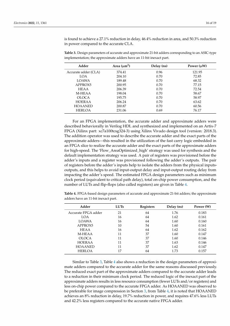
is found to achieve a 27.1% reduction in delay, 46.4% reduction in area, and 50.3% reductionin power compared to the accurate CLA.
Table 3. Design parameters of accurate and approximate 21-bit adders corresponding to an ASIC-typeimplementation; the approximate adders have an 11-bit inexact part.
Adder Area (µm2) Delay (ns) Power (µW)
Accurate adder (CLA) 374.41 0.96 121.95LOA 204.10 0.70 72.85
LOAWA 189.48 0.70 68.32APPROX5 200.95 0.70 77.15
HEAA 206.39 0.70 72.54M-HEAA 198.04 0.70 58.67OLOCA 195.75 0.70 58.97
HOERAA 206.24 0.70 63.62HOAANED 200.87 0.70 60.56
HERLOA 231.06 0.69 76.17
For an FPGA implementation, the accurate adder and approximate adders weredescribed behaviorally in Verilog HDL and synthesized and implemented on an Artix-7FPGA (Xilinx part: xc7a100tcsg324-3) using Xilinx Vivado design tool (version: 2018.3).The addition operator was used to describe the accurate adder and the exact parts of theapproximate adders—this resulted in the utilization of the fast carry logic embedded inan FPGA slice to realize the accurate adder and the exact parts of the approximate addersfor high-speed. The ‘Flow_AreaOptimized_high’ strategy was used for synthesis and thedefault implementation strategy was used. A pair of registers was provisioned before theadder’s inputs and a register was provisioned following the adder’s outputs. The pairof registers before the adder’s inputs help to isolate the adders from the physical inputs-outputs, and this helps to avoid input-output delay and input-output routing delay fromimpacting the adder’s speed. The estimated FPGA design parameters such as minimumclock period (equivalent to critical path delay), total on-chip power consumption, and thenumber of LUTs and flip-flops (also called registers) are given in Table 4.
Table 4. FPGA-based design parameters of accurate and approximate 21-bit adders; the approximateadders have an 11-bit inexact part.
Adder LUTs Registers Delay (ns) Power (W)
Accurate FPGA adder 21 64 1.76 0.183LOA 16 64 1.62 0.161
LOAWA 16 64 1.60 0.160APPROX5 10 54 1.60 0.161
HEAA 16 64 1.62 0.162M-HEAA 11 37 1.60 0.147OLOCA 11 37 1.60 0.146
HOERAA 11 37 1.63 0.146HOAANED 11 37 1.62 0.147
HERLOA 17 64 1.73 0.157
Similar to Table 3, Table 4 also shows a reduction in the design parameters of approxi-mate adders compared to the accurate adder for the same reasons discussed previously.The reduced exact part of the approximate adders compared to the accurate adder leadsto a reduction in their minimum clock period. The reduced logic of the inexact part of theapproximate adders results in less resource consumption (fewer LUTs and/or registers) andless on-chip power compared to the accurate FPGA adder. As HOAANED was observed tobe preferable for image compression in Section 3, from Table 4, it is noted that HOAANEDachieves an 8% reduction in delay, 19.7% reduction in power, and requires 47.6% less LUTsand 42.2% less registers compared to the accurate native FPGA adder.
Electronics 2022, 11, 1361 17 of 19
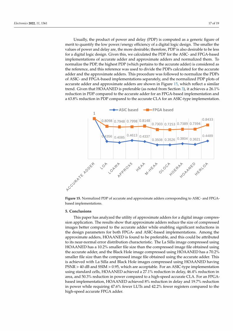
Usually, the product of power and delay (PDP) is computed as a generic figure ofmerit to quantify the low power/energy efficiency of a digital logic design. The smaller thevalues of power and delay are, the more desirable; therefore, PDP is also desirable to be lessfor a digital logic design. Given this, we calculated the PDP for the ASIC- and FPGA-basedimplementations of accurate adder and approximate adders and normalized them. Tonormalize the PDP, the highest PDP (which pertains to the accurate adder) is considered asthe reference, and this reference was used to divide the PDPs calculated for the accurateadder and the approximate adders. This procedure was followed to normalize the PDPsof ASIC- and FPGA-based implementations separately, and the normalized PDP plots ofaccurate adder and approximate adders are shown in Figure 15, which reflect a similartrend. Given that HOAANED is preferable (as noted from Section 3), it achieves a 26.1%reduction in PDP compared to the accurate adder for an FPGA-based implementation anda 63.8% reduction in PDP compared to the accurate CLA for an ASIC-type implementation.
Electronics 2022, 11, x FOR PEER REVIEW 18 of 20
Figure 15. Normalized PDP of accurate and approximate adders corresponding to ASIC- and
FPGA-based implementations.
5. Conclusions
This paper has analyzed the utility of approximate adders for a digital image com-
pression application. The results show that approximate adders reduce the size of com-
pressed images better compared to the accurate adder while enabling significant reduc-
tions in the design parameters for both FPGA- and ASIC-based implementations. Among
the approximate adders, HOAANED is found to be preferable, and this could be at-
tributed to its near-normal error distribution characteristic. The La Silla image compressed
using HOAANED has a 10.2% smaller file size than the compressed image file obtained
using the accurate adder, and the Black Hole image compressed using HOAANED has a
70.2% smaller file size than the compressed image file obtained using the accurate adder.
This is achieved with La Silla and Black Hole images compressed using HOAANED hav-
ing PSNR > 40 dB and SSIM > 0.95, which are acceptable. For an ASIC-type implementa-
tion using standard cells, HOAANED achieved a 27.1% reduction in delay, 46.4% reduc-
tion in area, and 50.3% reduction in power compared to a high-speed accurate CLA. For
an FPGA-based implementation, HOAANED achieved 8% reduction in delay and 19.7%
reduction in power while requiring 47.6% fewer LUTs and 42.2% fewer registers com-
pared to the high-speed accurate FPGA adder.
Author Contributions: Conceptualization, P.B. and R.N.; methodology, P.B. and R.N.; software,
P.B. and R.N.; validation, P.B. and R.N.; investigation, P.B. and R.N.; resources, D.L.M.; data cura-
tion, P.B. and R.N.; writing—original draft preparation, P.B. and R.N.; writing–review & editing,
P.B.; visualization, P.B. and R.N.; supervision, P.B. and D.L.M.; project administration, P.B. and
D.L.M.; funding acquisition, D.L.M. All authors have read and agreed to the published version of
the manuscript.
Funding: This research was funded by the Ministry of Education (MOE), Singapore under Aca-
demic Research Fund Tier-2 grant number MOE2018-T2-2-024.
Data Availability Statement: All data are available within the manuscript.
Conflicts of Interest: The funders had no role in the design of the study; in the collection, analyses,
or interpretation of data; in the writing of the manuscript, or in the decision to publish the results.
References
1. Han, J.; Orshansky, M. Approximate computing: An emerging paradigm for energy-efficient design. In Proceedings of the 18th
IEEE European Test Symposium, Avignon, France, 27–31 May 2013.
1
0.4356 0.40850.4613 0.4337
0.3508 0.3526 0.3804 0.36210.4489
1
0.8098 0.7948 0.7998 0.81480.7303 0.7253 0.7389 0.7394
0.8433
ASIC based FPGA based
Figure 15. Normalized PDP of accurate and approximate adders corresponding to ASIC- and FPGA-based implementations.
5. Conclusions
This paper has analyzed the utility of approximate adders for a digital image compres-sion application. The results show that approximate adders reduce the size of compressedimages better compared to the accurate adder while enabling significant reductions inthe design parameters for both FPGA- and ASIC-based implementations. Among theapproximate adders, HOAANED is found to be preferable, and this could be attributedto its near-normal error distribution characteristic. The La Silla image compressed usingHOAANED has a 10.2% smaller file size than the compressed image file obtained usingthe accurate adder, and the Black Hole image compressed using HOAANED has a 70.2%smaller file size than the compressed image file obtained using the accurate adder. Thisis achieved with La Silla and Black Hole images compressed using HOAANED havingPSNR > 40 dB and SSIM > 0.95, which are acceptable. For an ASIC-type implementationusing standard cells, HOAANED achieved a 27.1% reduction in delay, 46.4% reduction inarea, and 50.3% reduction in power compared to a high-speed accurate CLA. For an FPGA-based implementation, HOAANED achieved 8% reduction in delay and 19.7% reductionin power while requiring 47.6% fewer LUTs and 42.2% fewer registers compared to thehigh-speed accurate FPGA adder.
Electronics 2022, 11, 1361 18 of 19
Author Contributions: Conceptualization, P.B. and R.N.; methodology, P.B. and R.N.; software, P.B.and R.N.; validation, P.B. and R.N.; investigation, P.B. and R.N.; resources, D.L.M.; data curation, P.B.and R.N.; writing—original draft preparation, P.B. and R.N.; writing—review & editing, P.B.; visual-ization, P.B. and R.N.; supervision, P.B. and D.L.M.; project administration, P.B. and D.L.M.; fundingacquisition, D.L.M. All authors have read and agreed to the published version of the manuscript.
Funding: This research was funded by the Ministry of Education (MOE), Singapore under AcademicResearch Fund Tier-2 grant number MOE2018-T2-2-024.
Data Availability Statement: All data are available within the manuscript.
Conflicts of Interest: The funders had no role in the design of the study; in the collection, analyses,or interpretation of data; in the writing of the manuscript, or in the decision to publish the results.
References1. Han, J.; Orshansky, M. Approximate computing: An emerging paradigm for energy-efficient design. In Proceedings of the 18th
IEEE European Test Symposium, Avignon, France, 27–31 May 2013.2. Venkataramani, S.; Chakradhar, S.T.; Roy, K.; Raghunathan, A. Approximate computing and the quest for computing efficiency.
In Proceedings of the 52nd Design Automation Conference, San Francisco, CA, USA, 8–12 June 2015.3. Breuer, M.A.; Zhu, H. Error-tolerance and multi-media. In Proceedings of the International Conference on Intelligent Information
Hiding and Multimedia Signal Processing, Pasadena, CA, USA, 18–20 December 2006.4. Zhu, N.; Goh, W.L.; Zhang, W.; Yeo, K.S.; Kong, Z.H. Design of low-power high-speed truncation-error-tolerant adder and its
application in digital signal processing. IEEE Trans. VLSI Syst. 2010, 18, 1225–1229.5. Nair, R. Big data needs approximate computing: Technical perspective. Commun. ACM 2015, 58, 104. [CrossRef]6. Panda, P.; Sengupta, A.; Sarwar, S.S.; Srinivasan, G.; Venkataramani, S.; Raghunathan, A.; Roy, K. Cross-layer approximations for
neuromorphic computing: From devices to circuits and systems. In Proceedings of the 53rd Design Automation Conference,Austin, TX, USA, 5–9 June 2016.
7. Sarwar, S.S.; Srinivasan, G.; Han, B.; Wijesinghe, P.; Jaiswal, A.; Panda, P.; Raghunathan, A.; Roy, K. Energy efficient neuralcomputing: A study of cross-layer approximations. IEEE J. Emerg. Sel. Top. Circuits Syst. 2018, 8, 796–809. [CrossRef]
8. Sampson, A.; Deitl, W.; Fortuna, D.; Gnanapragasam, D.; Ceze, L.; Grossman, D. EnerJ: Approximate data types for safe andgeneral low-power computation. ACM Sigplan Not. 2011, 46, 164–174. [CrossRef]
9. Sampson, K.; Nelson, J.; Strauss, K.; Ceze, L. Approximate storage in solid-state memories. ACM Trans. Comput. Syst. 2014, 32,1–23. [CrossRef]
10. Zhang, H.; Putic, M.; Lach, J. Low power GPGPU computation with imprecise hardware. In Proceedings of the 51st DesignAutomation Conference, San Francisco, CA, USA, 1–5 June 2014.
11. Jiang, H.; Liu, C.; Liu, L.; Lombardi, F.; Han, J. A review, classification, and comparative evaluation of approximate arithmeticcircuits. ACM J. Emerg. Technol. Comput. Syst. 2017, 13, 1–37. [CrossRef]
12. Hennessy, J.; Patterson, D. Computer Architecture: A Quantitative Approach, 5th ed.; Morgan Kaufmann: Burlington, MA, USA,2003; ISBN 9780123838735.
13. Garside, J.D. A CMOS VLSI implementation of an asynchronous ALU. In Proceedings of the IFIP Working Conference onAsynchronous Design Methodologies, Manchester, UK, 31 March–2 April 1993.
14. Wanhammar, L. DSP Integrated Circuits, 1st ed.; Academic Press: Cambridge, MA, USA, 1999; ISBN 9780127345307.15. Almurib, H.A.F.; Nandha Kumar, T.; Lombardi, F. Approximate DCT image compression using inexact computing. IEEE Trans.
Comput. 2018, 67, 149–159. [CrossRef]16. Bouguezel, S.; Ahmad, M.O.; Swamy, M.N.S. Low-complexity 8×8 transform for image compression. Electron. Lett. 2008, 44,
1249–1250. [CrossRef]17. Cintra, R.J.; Bayer, F.M. A DCT approximation for image compression. IEEE Signal Process. Lett. 2011, 18, 579–582. [CrossRef]18. Potluri, U.S.; Madanayake, A.; Cintra, R.J.; Bayer, F.M.; Kulasekara, S.; Edirisuriya, A. Improved 8-point approximate DCT for
image and video compression requiring only 14 additions. IEEE Trans. Circuits Syst. I Regul. Pap. 2014, 61, 1727–1740. [CrossRef]19. Da Silveira, T.L.T.; Bayer, F.M.; Cintra, R.J.; Kulasekara, S.; Madanayake, A.; Kozakevicius, A.J. An orthogonal 16-point
approximate DCT for image and video compression. Multidimens. Syst. Signal Process. 2016, 27, 87–104. [CrossRef]20. Huang, J.; Nandha Kumar, T.; Almurib, H.A.F.; Lombardi, F. A deterministic low-complexity approximate (multiplier-less)
technique for DCT computation. IEEE Trans. Circuits Syst. I Regul. Pap. 2019, 66, 3001–3014. [CrossRef]21. Raha, A.; Jayakumar, H.; Raghunathan, V. Input-based dynamic reconfiguration of approximate arithmetic circuits for video
encoding. IEEE Trans. VLSI Syst. 2016, 24, 846–857. [CrossRef]22. Balasubramanian, P.; Maskell, D.L. Factorized carry lookahead adders. In Proceedings of the IEEE 14th International Symposium
on Signals, Circuits and Systems, Iasi, Romania, 11–12 July 2019.23. Mahdiani, H.R.; Ahmadi, A.; Fakhraie, S.M.; Lucas, C. Bio-inspired computational blocks for efficient VLSI implementation of
soft-computing applications. IEEE Trans. Circuits Syst. I Regul. Pap. 2010, 57, 850–862. [CrossRef]
Electronics 2022, 11, 1361 19 of 19
24. Albicocco, P.; Cardarilli, G.C.; Nannarelli, A.; Petricca, M.; Re, M. Imprecise arithmetic for low power image processing. InProceedings of the 46th Asilomar Conference on Signals, Systems and Computers, Pacific Grove, CA, USA, 4–7 November 2012.
25. Balasubramanian, P.; Maskell, D.L. Hardware optimized and error reduced approximate adder. Electronics 2019, 8, 1212. [CrossRef]26. Gupta, V.; Mohapatra, D.; Raghunathan, A.; Roy, K. Low-power digital signal processing using approximate adders. IEEE Trans.
Comput. Aided Des. Integr. Circuits Syst. 2013, 32, 124–137. [CrossRef]27. Balasubramanian, P.; Maskell, D.L. Hardware efficient approximate adder design. In Proceedings of the IEEE Region 10
Conference, Jeju, Korea, 28–31 October 2018.28. Balasubramanian, P.; Maskell, D.L.; Prasad, K. Approximate adder with reduced error. In Proceedings of the IEEE 31st
International Conference on Microelectronics, Nis, Serbia, 16–18 September 2019.29. Dalloo, A.; Najafi, A.; Garcia-Ortiz, A. Systematic design of an approximate adder: The optimized lower part constant-OR adder.
IEEE Trans. VLSI Syst. 2018, 26, 1595–1599. [CrossRef]30. Balasubramanian, P.; Nayar, R.; Maskell, D.L.; Mastorakis, N.E. An approximate adder with a near-normal error distribution:
Design, error analysis and practical application. IEEE Access 2021, 9, 4518–4530. [CrossRef]31. Seo, H.; Yang, Y.S.; Kim, Y. Design and analysis of an approximate adder with hybrid error reduction. Electronics 2020, 9, 471.
[CrossRef]32. Snigdha, F.S.; Sengupta, D.; Hu, J.; Sapatnekar, S.S. Optimal design of JPEG hardware under the approximate computing
paradigm. In Proceedings of the 53rd Design Automation Conference, Austin, TX, USA, 5–9 June 2016.33. Lam, E.Y.; Goodman, J.W. Discrete cosine transform domain restoration of defocused images. Appl. Opt. 1998, 37, 6213–6218.
[CrossRef] [PubMed]34. Auburn nights at La Silla. Available online: https://www.eso.org/public/images/lasilla-2019-doyen-CC/ (accessed on 26
August 2021).35. First Image of a Black Hole. Available online: https://www.eso.org/public/images/eso1907a/ (accessed on 8 August 2021).36. Bovik, A. Handbook of Image and Video Processing, 2nd ed.; Academic Press: Orlando, FL, USA, 2005; ISBN 9780080533612.37. Wang, Z.; Bovik, A.C.; Sheikh, H.R.; Simoncelli, E.P. Image quality assessment: From error visibility to structural similarity. IEEE
Trans. Image Process. 2004, 13, 600–612. [CrossRef] [PubMed]38. Willmott, C.J.; Ackleson, S.G.; Davis, R.E.; Feddema, J.J.; Klink, K.M.; Legates, D.R.; O’Donnell, J.; Rowe, C.M. Statistics for the
evaluation and comparison of models. J. Geophys. Res. 1985, 90, 8995–9005. [CrossRef]39. Synopsys SAED_EDK32/28_CORE Databook. Revision 1.0.0. January 2012. Available online: https://www.synopsys.com/
community/university-program/teaching-resources.html (accessed on 18 August 2021).


