Embed Size (px)
Citation preview

WIKA Alexander Wiegand GmbH & Co. KGAlexander-Wiegand-Straße 3063911 Klingenberg/GermanyPhone (+49) 93 72/132-0Fax (+49) 93 72/132-406E-Mail [email protected]
Digital Indicator, Model DI35-M
WIKA Operating Instructions DI35-M V B0.1 • 04/2003
Operating Instructions

Operating Instructions Digital Indicator DI35-M
V B0.1 • 04/2003 - 2 -
1. Brief description..........................................................................................................................42. Safety instructions ......................................................................................................................42.1. Proper use ...................................................................................................................................42.2. Control of the device..................................................................................................................42.3. Installation...................................................................................................................................42.4. Notes on installation...................................................................................................................43. Assembly .....................................................................................................................................53.1. Insertion in the panel cut-out ....................................................................................................53.2. Dismantling..................................................................................................................................63.3. Dimension strip...........................................................................................................................64. Electrical connection..................................................................................................................74.1.1. Upper connecting terminals....................................................................................................74.1.2. Lower connecting terminals....................................................................................................84.2. Connecting examples ..............................................................................................................105. Operation...................................................................................................................................135.1. Operating and display elements ..........................................................................................135.1.1. Keys .........................................................................................................................................135.1.2. Displays ...................................................................................................................................135.1.3. Dimension window.................................................................................................................135.2. Switching on..............................................................................................................................135.3. Starting sequence ....................................................................................................................145.4. MIN/MAX memory....................................................................................................................145.5. Overflow/Underflow..................................................................................................................145.6. Relays ........................................................................................................................................155.6.1. Optical response, flashing display.......................................................................................165.7. Analogue output .......................................................................................................................165.8. Digital input................................................................................................................................166. Interface.....................................................................................................................................176.1. Operating modes PN34...........................................................................................................176.2. RS232 / RS485.........................................................................................................................176.2.1. Serial special commands......................................................................................................186.2.2. Treatment of calibration points.............................................................................................197. Programming.............................................................................................................................207.1. Programming procedure .........................................................................................................207.1.1. Changing from programming to operating mode..............................................................227.2. Universal measuring input ......................................................................................................227.2.1. Calibration modes ..................................................................................................................227.2.2. Measuring input PN 0 ............................................................................................................247.2.3. Scaling PN1 and PN2............................................................................................................247.2.4. Decimal point PN3 .................................................................................................................247.2.5. Offset shift PN5 ......................................................................................................................247.2.6. Thermocouple reference junction PN6...............................................................................247.2.7. Display time PN 13 ................................................................................................................247.2.8. Measuring time PN 14...........................................................................................................247.2.9. Zero point suppression PN 18..............................................................................................257.2.10. Analogue output PN20 and 21.............................................................................................257.2.11. Security setting, user level PN50 to 52 ..............................................................................257.2.12. Setpoints..................................................................................................................................267.2.13. Linearisation PN100 to 130 ..................................................................................................267.2.14. Serial number PN200............................................................................................................26

Operating Instructions Digital Indicator DI35-M
V B0.1 • 04/2003 - 3 -
8. Program table ........................................................................................................................... 279. Technical data .......................................................................................................................... 3110. Error elimination....................................................................................................................... 3410.1. Questions and answers ........................................................................................................ 3410.2. Reset to default values ......................................................................................................... 34

Operating Instructions Digital Indicator DI35-M
V B0.1 • 04/2003 - 4 -
1. Brief descriptionA wide variety of different sensors can be connected directly to the DI35-M. The 5-digitdisplay shows the measurements or the scaled value of the measurement. Duringprogramming, the display is used to indicate the set values and the user prompts. Amaximum of 4 relays are available to monitor threshold values. Via the serial interface,data can be communicated from and to the device.
2. Safety instructionsPlease read the users guide before installation and keep it for future reference.
2.1. Proper useThe DI35 is designed for the evaluation and display of sensor signals. With the setpoints, itis possible to perform simple control tasks.
Danger! Careless use or improper operation can result in personal injury and/ordamage to the equipment.
2.2. Control of the deviceThe panel meters are checked before dispatch and sent out in perfect condition. Shouldthere be any visible damage, we recommend close examination of the packaging. Pleaseinform the supplier immediately of any damage.
2.3. InstallationThe DI35 must be installed by a suitably qualified specialist (e.g. with a qualification inindustrial electronics).
2.4. Notes on installationq There must be no magnetic or electric fields in the vicinity of the device, e.g. due to
transformers, mobile phones or electrostatic discharge. 1
q The fuse rating of the supply voltage should not exceed a value of 6A N.B. fuse.q Do not install inductive consumers (relays, solenoid valves etc.) near the device and
suppress any interference with the aid of RC spark extinguishing combinations or free-wheeling diodes.
q Keep input, output and supply lines separate from one another and do not lay themparallel with each other. Position go and return lines next to one another. Wherepossible use twisted pair.
q Screen off and twist sensor lines. Do not lay current-carrying lines in the vicinity1.Connect the screening on one side on a suitable potential equaliser.
q The device is not suitable for installation in areas where there is a risk of explosion.q Any electrical connection deviating from the connection diagram can endanger human
life and/or can destroy the equipment.q Do not install several devices immediately above one another (ambient temperature)1
1 see technical data

Operating Instructions Digital Indicator DI35-M
WIKA Alexander Wiegand GmbH & Co. KGAlexander-Wiegand-Straße 3063911 Klingenberg/GermanyPhone (+49) 93 72/132-0Fax (+49) 93 72/132-406E-Mail [email protected]
3. AssemblyThe DI35 is intended for installation in a control panel. Before assembly, a cut-out mustbe made to accommodate the device. The sizes and tolerances are given in the technicaldata.On front of the DI35 are the operating and display elements.On the sides are the fixing elements to mount the device in the panel.On the back are the terminals for all the electrical connections.A sealing strip is inserted between the contact surface of the front collar and the controlpanel.
3.1. Insertion in the panel cut-out
I. Before inserting the unit, the side fixing elements must be pulled from the rail. Todo this, slightly raise the screw head of the fixing element and pull the fixing elementbackwards at the same time.
II. Lay the sealing strip around the unit and push it up against the front collar. Thenpush the unit from the front through the cut-out.
III. Then place the fixing elements into the guide rails from the rear. While doing this,hold the unit from the front secure in the cut-out. Then, using a slotted screw driver,push the fixing elements as far as possible towards the front panel from the rear.Check that the sealing strip is properly positioned between the front collar and thecontrol panel and correct it if necessary.
IV. Finally secure the device by tightening the screws on the fixing elements until theyturn freely. The fixing elements have a slip coupling to prevent any overtightening ofthe thread; they hold the unit tight with the optimum amount of force.

Operating Instructions Digital Indicator DI35-M
V B0.1 • 04/2003 - 6 -
View of the DI35
3.2. Dismantling
To remove the unit, follow the same steps as described for Assembly in reverse order.
For the version featuring the protective system IP65, a new sealing strip must be usedwhen the unit is replaced.
3.3. Dimension stripA strip with a physical unit can be inserted in the dimension window, see Chapter 5.1.3.To do this, take the following steps:I. Insert a slotted screw driver (size 0 blade) in the ejection slot at the bottom of the front
panel and lever out the front.II. On the back of the front panel, towards the outer edge is a slit in to accommodate the
appropriate strip.III. Insert a suitable dimension strip.IV. Insert the front panel into the front collar of the unit and press slightly against the
upper and lower edges so that it snaps back into the housing.V. Check that the plastic elements on the front have not bent the LEDs towards the back.
This is the case if the digits are not sharp. If this does happen, remove the front panelagain and replace it carefully.
48
111
5
fixing el
ementSeal
Display and operating elements
upperconnection terminal
141
134 with s
crew-typ
e terminal
148 with p
lug-in te
rminalEjector groove96
lowerconnection terminal

Operating Instructions Digital Indicator DI35-M
V B0.1 • 04/2003 - 7 -
4. Electrical connectionAll the necessary signals for operation are connected to the rear terminals.
4.1.1. Upper connecting terminalsThe setpoints are tapped on the 12-pole connector strip. Depending on the version, thereare between zero and four changeover contacts (Normally-Close, COMmon,Normally-Open).
Relay 1 Relay 2 Relay 3 Relay 421 22 23 24 25 26 27 28 29 30 31 32NC NO COM NC NO COM NO NC COM NO NC COM
Via the 3-pole connector strip, a serial interface is connected. If neither of the two optionsare implemented in the unit, the respective connecting terminals will be missing.
RS232 RS48541 42 43 or 41 42 43GND (RS) RxD TxD GND (RS) Data B (+) Data A (–)
The lines for the RS232 interface must be connected crosswise, so that TxD of the DI35 isconnected to RxD of the other device and RxD of the DI35 to TxD of the other device.
Connection pattern PC or SPS ⇔ DI35
The RS485 interface is connected via a shielded data line with a twisted pair.At each end of the bus, a termination of the bus lines must be connected. This is necessaryto guarantee reliable data transmission on the bus. For this, a resistance of 120 Ohm isinserted between the lines Data B (+) and Data A (–).
Caution! The potential reference can lead to a compensating current(interface ⇔ measuring input) with a non-galvanically insulated interface and canthus affect the measuring signals.

Operating Instructions Digital Indicator DI35-M
V B0.1 • 04/2003 - 8 -
4.1.2. Lower connecting terminalsInput signal, analogue output, sensor supply and supply voltage are connected to the lowerconnecting terminal.
Terminal 1–7 Input signalsThe input signal is connected to these terminals. The DI35-M features a universalmeasuring input to which most conventional sensors can be directly connected.One sensor can be connected to the input of the DI35-M.
Sensor 1 2 3 4 5 6 7–1...10 V–1...5 V
+ U – U
-0,5...2,5 V-0,5...1,25 V– 500...600 mV± 300 mV± 150 mV± 75 mV± 35 mV± 18 mV
+ U – U
0/4...20mA0...5 mA0...2 mA
+ I – I
PTxxx 2-wire
+ Forcebridgedto term3
– Forcebridgedto term4
+ Sense – Sense
PTxxx 3-wire
+ Forcebridgedto term3
– Force + Sense – Sense
PTxxx4-wire
+ Force – Force + Sense – Sense
Thermocouples + Signal – SignalResistance2-wire
+ Forcebridgedto term3
– Forcebridgedto term4
+ Sense – Sense
Resistance3-wire
+ Forcebridgedto term3
– Force + Sense – Sense
Resistance4-wire
+ Force – Force + Sense – Sense
Examples of the connections for various sensors can be found in section 4.2 Connectingexamples.

Operating Instructions Digital Indicator DI35-M
V B0.1 • 04/2003 - 9 -
Terminals 8–9 Analogue outputThe signal for the analogue output is provided on these terminals. Depending on thecapabilities of the unit, a current or voltage signal can be tapped.
8 9Analogueoutput +
Analogueoutput –
Terminals 10–11 Sensor supplyThe sensor supply is provided on these connectors. The sensor supply is galvanicallyinsulated from the measuring input. The voltage of the sensor supply varies according tothe capabilities of the unit.
10 11Sensorsupply+
Sensorsupply–
Terminals 13–14 Supply voltageThe supply voltage for the unit is connected to these terminals. The supply voltage isgalvanically insulated from the measuring input.
13 14 Supply voltageL+ L– 24V DC voltageL N 115 or 230V AC,
depending on version
Terminal 12 Digital inputWith the implemented option "Digital input", a potential-free contact can be connected tothis terminal for controlling specific functions in the unit such as reset, taring, hold etc. Forthis function, it is necessary to also implement the same sensor supply as is used for supplyand to which this connection electrically relates.
12Digitalinput

Operating Instructions Digital Indicator DI35-M
V B0.1 • 04/2003 - 10 -
4.2. Connecting examplesThis sections gives a few examples of practical connections. Other connection options canbe combined from the various examples.
Measuring a current signal from a 2-line transmitter using the sensor supply; supplyvoltage 230 V/AC
Measurement of a voltage signal (5 V or 10 V) from a 3-wire transmitter using thesensor supply; supply voltage 24 V/DC
Measurement of a voltage signal (≤ 2.5 V) from a 3-wire transmitter using the sensorsupply; supply voltage 24 V/DC
2 3 4 5 6 7 8 9 10 11
In 2 In 3 In 4 In 5 In 6 In 7 + - + -
Input Analogueoutput
Sensorsupply
U?B1
In 1
1 12
L+
13
Supply
14
L-Din
Dig
ital
inpu
t
24V/DC
+ -+ -
2 3 4 5 6 7 8 9
In 2 In 3 In 4 In 5 In 6 In 7 + -
Input Analogueoutput
U?B1
In 1
1
230V/AC
10 11
+ -
Sensorsupply
12
L
13
Supply
14
NDin
+ -
230V/AC
2 3 4 5 6 7 8 9 10 11
In 2 In 3 In 4 In 5 In 6 In 7 + - + -
Input Analogueoutput
Sensor-supply
I?B1
In 1
1 12
L
13
Supply
14
NDin
Dig
ital
inpu
t
+ -

Operating Instructions Digital Indicator DI35-M
V B0.1 • 04/2003 - 11 -
Measurement of a resistance thermometer (e.g. PT 100) or resistance in the 2-wiretechnology; supply voltage 230 V/AC
Measurement of a resistance thermometer (e.g. PT100) or resistance in the 3-wire;supply voltage 24 V/AC
Measurement of a resistance thermometer (e.g. PT100) or resistance in the 4-wiretechnology; supply voltage 24 V/AC
Measurement of a potentiometer in the 4-wire technology
24V/DC
+ -2 3 4 5 6 7 8 9 10 11
In 2 In 3 In 4 In 5 In 6 In 7 + - + -
Input Analogueoutput
Sensorsupply
In 1
1 12
L+
13
Supply
14
L-Din
Dig
ital
inpu
t
230V/AC
2 3 4 5 6 7 8 9 10 11
In 2 In 3 In 4 In 5 In 6 In 7 + - + -
Input Analogueoutput
Sensorsupply
In 1
1 12
L
13
Supply
14
NDin
Dig
ital
inpu
t
230V/AC
2 3 4 5 6 7 8 9 10 11
In 2 In 3 In 4 In 5 In 6 In 7 + - + -
Input Analogueoutput
Sensorsupply
In 1
1 12
L
13
Supply
14
NDin
Dig
ital
inpu
t
230V/AC
2 3 4 5 6 7 8 9 10 11
In 2 In 3 In 4 In 5 In 6 In 7 + - + -
Input Analogueoutput
Sensorsupply
In 1
1 12
L
13
Supply
14
NDin
Dig
ital
inpu
t

Operating Instructions Digital Indicator DI35-M
V B0.1 • 04/2003 - 12 -
Measurement of a potentiometer in the 2-wire technology.
Measurement of a thermocouple; connection of the analogue output; connection of thedigital input to the sensor supply; supply voltage 230 V/AC.
Measurement of the shunt resistance; connection to the analogue output; connection of thedigital input to the sensor supply; supply voltage 230 V/AC.
230V/AC
2 3 4 5 6 7 8 9 10 11
In 2 In 3 In 4 In 5 In 6 In 7 + - + -
Input Analogueoutput
Sensorsupply
In 1
1 12
L
13
Supply
14
NDin
Dig
ital
inpu
t
S1+ -+ - +
230V/AC
2 3 4 5 6 7 8 9 10 11
In 2 In 3 In 4 In 5 In 6 In 7 + - + -
Input Analogueoutput
Sensorsupply
In 1
1 12
L
13
Supply
14
NDin
Dig
ital
inpu
t
S1+ -+ - +
I
230V/AC
2 3 4 5 6 7 8 9 10 11
In 2 In 3 In 4 In 5 In 6 In 7 + - + -
Input Analogueoutput
Sensorsupply
In 1
1 12
L
13
Supply
14
NDin
Dig
ital
inpu
t

Operating Instructions Digital Indicator DI35-M
V B0.1 • 04/2003 - 13 -
5. OperationThe unit is operated via the [P], [UP] and [DOWN] keys.
5.1. Operating and display elements
5.1.1. KeysThe DI35 has three keys with which you can parameterise and call up various functionsduring operation.
1 Program key[P]
With the program key, you can call up the programming mode orperform various functions in the programming mode.
2 Minus key[DOWN]
With the minus key, you can call up the MIN memory or alterparameters in the programming mode.
3 Plus key[UP]
With the plus key, you can call up the MAX memory or alter parametersin the programming mode.
5.1.2. DisplaysThe DI35 has a 5-digit, 7-segment display and four LEDs.
4 Seven-segmentdisplay
The seven-segment display displays measurements or, duringprogramming, the program numbers or parameters.
5 Setpoint display The setpoint display indicates the state of the relays. If a relay isswitched, the LED lights up. If relays are not implemented, thesedisplays can be used for the optical feedback of threshold values.
5.1.3. Dimension window
6 Dimensionwindow
The dimension window shows the factory-set physical unit for themeasurement. The dimension can also be changed by the user asdescribed in Chapter 3.3
5.2. Switching onBefore switching on you have to check all the electrical connections to make sure they arecorrect. On completion of the installation, the device can be switched on by applying thesupply voltage.
631 2
4
P2
Program key [P]Minus key [DOWN]Plus key [UP]Seven-segment displaySetpoint display 1-4Dimension window
1
4 3
5
1 3
2
45
6

Operating Instructions Digital Indicator DI35-M
V B0.1 • 04/2003 - 14 -
5.3. Starting sequenceDuring the switching-on process, a segment test is performed for approx. 1 s, whereby allLEDs on the front (including setpoint LEDs) are triggered. After this, the type of software isindicated for approx. 1 s and then, also for 1 s, the software version. After the startingprocedure, the unit changes to operation/display mode.
5.4. MIN/MAX memoryThe measured minimum and maximum values are saved in a voaltile memory in the unitand get lost when the unit is switched off.You can call up the contents of the memory by pushing (less than 1 s) the [UP] or [DOWN]key. The relevant value is indicated for approx. 7 s. By briefly pressing the same key again,you will return immediately to the display mode.
[UP] ⇒ Display of the MAX value[DOWN] ⇒ Display of the MIN value
You can erase the value shown in the display by simultaneously operating the[UP] & [DOWN] keys. The erasure is acknowledged by horizontal bars.
5.5. Overflow/UnderflowAn overflow of the display is indicated by horizontal bars at the top of the 7-segmentdisplay.
An underflow of the display is indicated by horizontal bars at the bottom of the 7-segmentdisplay.

Operating Instructions Digital Indicator DI35-M
V B0.1 • 04/2003 - 15 -
5.6. RelaysWith the aid of the LEDs next to the 7-segment display, you can view the switching state ofthe relays. An active relay is indicated by the relevant LED lighting up.
The relays have the following properties with regard to their switching characteristics:
Setpoint x Deactivated, activatedThreshold Threshold value for switchoverHysteresis Width of the window between the switch thresholdsOperating principle active above SP value / active below SP valueSwitch-on delay Time between reaching the threshold and the
resultant switching on of the relaySwitch-off delay Time between reaching the threshold and the
resultant switching off of the relay
active above SP valueThe setpoint is off belowthe threshold and on onreaching the threshold.
active below SP valueThe setpoint is on belowthe threshold and switchedoff on reaching thethreshold.
Switch-on delayThe relay is on 10 s afterreaching the threshold; brieflyexceeding the threshold doesnot lead to the relay beingswitched on. The switch-offdelay functions in a similarmanner, in other words itkeeps the setpoint switchedon until the parameterisedtime has elapsed.
setpoint
display
rais
ed
falle
n
hysteresis
on
off
tresh
old
setpoint
display
falle
n
rais
ed
hysteresis
on
off
tresh
old
input
time [s]
10
0
switch-on delay 10 son
offtime [s]
treshold
5
5

Operating Instructions Digital Indicator DI35-M
V B0.1 • 04/2003 - 16 -
5.6.1. Optical response, flashing displayThe switching on of one or more setpoints can also be set to trigger a flashing of the displayto enhance the optical response.
Example:Let us assume the threshold for flashing of the display is set at setpoint 2.If setpoint 1 is exceeded and setpoint 2 is not, the setpoint LED 1 lights up permanently.If setpoint 2 exceeds the threshold, the 7-segment display will start to flash, setpoint 1 willlight up permanently and setpoint LED 2 will flash.The flashing enhances the optical response and the operator sees immediately that animportant threshold has been exceeded with this unit.
5.7. Analogue outputThe analogue output is used to rescale the determined values. The analogue output isparameterised via the two program numbers, "Offset" and "Full scale". With "Offset", thevalue is set at which the analogue output transmits the minimal value, and with "Full scale",the value at which the output transmits its maximum.
5.8. Digital inputThe digital input can be used to trigger certain specific functions in the unit, but will not bedealt with in more detail here.

Operating Instructions Digital Indicator DI35-M
V B0.1 • 04/2003 - 17 -
6. InterfaceThis section describes the interface.Pressing the ENTER or <CR> key is always denoted by ↵.
6.1. Operating modes PN34The interface can be operated in various modes that can be parameterised via the PN34.
PN34=0Standard mode in which the unit only replies if called on to do so. This mode is used onlyfor configurating.
PN34=1Transmission mode in which the measurements are transmitted via the serial interfacecyclically with the set measuring time.
The transmission mode is interrupted on receipt of “ > ↵ “ and the unit changes to standardmode. To change back to transmission mode, the display must be restarted, either byentering the command S ↵ or by switching the device off and on.
With the transmission mode, the display value is transmitted via the interface in ASCIIformat. Minus signs and decimal points are also transmitted so that the output can bedisplayed directly on a terminal or processed by a SPS. Zeros at the front are suppressedduring transmission. With an over or underflow, the display transmits horizontal bars(hyphens) " - - - - - ↵ ".
Examples: "0.00 ↵ " ; "-9.99 ↵ " ; "999.99 ↵ " ; "-123.45" ; " - - - - - ↵ "
With the aid of this simple protocol structure, the display data can be transferred very easilyto a PC etc. and further processed there. In the simplest case, a terminal program from theoperating system is sufficient to store the received data in a file.
6.2. RS232 / RS485All DI35 units can be programmed or configurated via an interface. The units do not haveany interface as standard.
For configuration, a terminal program or special programming software can be used.
The communication is a straight point-to-point connection. The baud rate is set to 9600baud, with 8 databits, without parity and one stopbit.
Configuration is performed by transmitting ASCII symbols.
The structure of a command: Program number / Command / Value/ ↵
Program number see program number table
Command = describe a parameter with a decimal valueB describe a parameter with a binary value
Value A value from the range of values given in the programnumber table
↵ ENTER or <CR>, conclusion of any command
Operating Instructions Digital Indicator DI35-M
V B0.1 • 04/2003 - 18 -
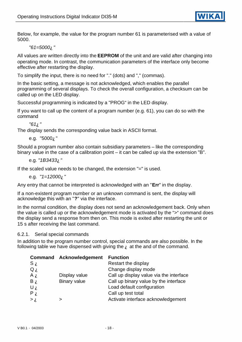
Below, for example, the value for the program number 61 is parameterised with a value of5000.
"61=5000↵"
All values are written directly into the EEPROM of the unit and are valid after changing intooperating mode. In contrast, the communication parameters of the interface only becomeeffective after restarting the display.
To simplify the input, there is no need for "." (dots) and "," (commas).
In the basic setting, a message is not acknowledged, which enables the parallelprogramming of several displays. To check the overall configuration, a checksum can becalled up on the LED display.
Successful programming is indicated by a "PROG“ in the LED display.
If you want to call up the content of a program number (e.g. 61), you can do so with thecommand
"61↵"The display sends the corresponding value back in ASCII format.
e.g. "5000↵"
Should a program number also contain subsidiary parameters – like the correspondingbinary value in the case of a calibration point – it can be called up via the extension "B".
e.g. "1B3433↵"
If the scaled value needs to be changed, the extension "=" is used.
e.g. "1=12000↵"
Any entry that cannot be interpreted is acknowledged with an "Err" in the display.
If a non-existent program number or an unknown command is sent, the display willacknowledge this with an "?" via the interface.
In the normal condition, the display does not send an acknowledgement back. Only whenthe value is called up or the acknowledgement mode is activated by the “>“ command doesthe display send a response from then on. This mode is exited after restarting the unit or15 s after receiving the last command.
6.2.1. Serial special commandsIn addition to the program number control, special commands are also possible. In thefollowing table we have dispensed with giving the ↵ at the and of the command.
Command Acknowledgement FunctionS ↵ Restart the displayQ ↵ Change display modeA ↵ Display value Call up display value via the interfaceB ↵ Binary value Call up binary value by the interfaceU ↵ Load default configurationP ↵ Call up test total> ↵ > Activate interface acknowledgement

Operating Instructions Digital Indicator DI35-M
V B0.1 • 04/2003 - 19 -
6.2.2. Treatment of calibration pointsTo parameterise calibration points, the binary measurement and the scaled value must bepreset. Before this, the measuring input to be dealt with must be activated via PN15.
Accordingly, a calibration is made as follows:
I. Calibration with sensorFor the calibration, the binary value must be called up from the unit with the command"B↵". The unit sends the binary value of the A/D converter back via the interface.After this, the value can be transferred to the preset program number 2 with thecommand e.g. "2B8388608↵".The respective scaled measurement is then indicated without a decimal point by e.g."2=10↵".
II. RescalingWith a straight rescaling, only the scaled calibration point value has to be overwritten.With this command, the value for PN2 is programmed to 100."2=100 ↵"The binary value is retained.
III. Binary value preset ( extension "B" )Only the binary measurement of the calibration point is changed (e.g. "2B8388608" ).The respective scaled value is retained.
IV. Takeover of calibrationExisting calibrations can be taken over from one unit to another with the aid of PCsoftware. A PC program must call up the factory calibration of the source unit and thetarget unit, match the linearisation and write the calculated binary values and scalevalues to the target unit.

Operating Instructions Digital Indicator DI35-M
V B0.1 • 04/2003 - 20 -
P
P
P
7. ProgrammingIn the display, the program numbers (PN) are shown, right-justified, as a three-digit numberwith a P in front of them.
Display of e.g. program number 0
7.1. Programming procedureThe entire programming of the DI35 is done by the steps described below.
Change to programming modePushing the [P] key changes to programming mode. The unit goes to the lowest availableprogram number. If the programming lock is activated, the key must be pushed for at least1 s.
Example:Change to programming mode by pushingkey [P]. The first released program number (PN)appears, in this case PN0.
Change to other program numbersTo change between individual program numbers, hold the [P] key down and push the[UP] key for changing to a higher program number or the [DOWN] key for changing to alower number. By keeping the keys pushed, e.g. [P] & [UP], the display will begin, afterapprox. 1 s, to automatically run through the program numbers.
Example:A 3 is parameterised under PN1.Keep key [P] pushed and push the [UP] keyseveral times. PN1 appears in the display. Underthis parameter the full scale of the input 2 can bechanged.
Change to the parameterOnce the program number appears in the display, you can push the [DOWN] or [UP] keyto get to the parameters set for this program number. The currently stored parameters aredisplayed.
Example:By pushing the [DOWN] or [UP] key, thecurrently stored value for PN1 appears in thedisplay. In this case, it is 75,640.

Operating Instructions Digital Indicator DI35-M
V B0.1 • 04/2003 - 21 -
P
P
P
Changing a parameterAfter changing to the parameter, the lowest digit of the respective parameter flashes on thedisplay. The value can be changed with the [UP] or [DOWN] key. To move to the next digit,the [P] key must be briefly pushed. Once the highest digit has been set and confirmed with[P], the lowest digit will begin to flash again.
Example:The 0 is flashing this is the lowest digit and asksif you want to change it. Let us assume thefigure is to be changed from 75,640 to 75,000.Briefly push the [P] key to move to the next digit.The 4 begins to flash. Change the figure bypushing [UP] or [DOWN] to change the digit
from 4 to 0. Briefly push the [P] key to move on to the next digit. The 6 begins to flash.Change the digit by pushing [UP] or [DOWN] to move the 6 to a 0. Briefly push the [P] keyto move to the next digit. The 5 and 7 do not need to be changed.
Saving parametersAll parameters must be acknowledged by the user by pushing the [P] key for one second.The changed parameters are then taken over as the current operating parameters andsaved in the EEPROM.This is confirmed by horizontal bars lighting up in the display.
Example:Save the parameters by pushing [P] for 1 s.
All the newly entered data are confirmed by the unit. If no confirmation is received, therelevant parameters have not been saved.
Example:You receive confirmation from the unit that thechanges have been saved through theappearance of horizontal bars in the middlesegments.

Operating Instructions Digital Indicator DI35-M
V B0.1 • 04/2003 - 22 -
7.1.1. Changing from programming to operating modeIf no key is pushed in the programming mode for about 7 sec, the unit will returnautomatically to operating mode.
7.2. Universal measuring inputThe DI35-M is equipped with a universal measuring input that enables the signals from allkinds of different sensors to be measured direct. So that the unit can work according to thesignal generated by the sensor, the input must be configured. The basic parameter isalways set under PN 0.
Caution! For the unit to function correctly, it is absolutely essential that the right sensoris parameterised under program number 0. If a wrong sensor isparameterised there, the operating behaviour may be impaired.
7.2.1. Calibration modesThe unit offers various possibilities with which the DI35-M can be parameterised to themeasured values.
Factory calibrationAll the units are calibrated in the factory, whereby offset and full scale were saved for thevarious measuring ranges.
Factory calibration PN0 = 1...12For these parameters, new scaled display values can be allocated which are used forscaling the measurement on the display. For the offset, an input signal of 0 is assumed andfor full scale, the specific full scale of the parameterised measuring range.
For parameterising, no sensor signal has to be applied because stored values are used.Because of the differing input signals, the corresponding input configuration must beparameterised via PN 0.
For the sensor signal with 4...20 mA, for example, PN0 = 2 has to be parameterised.
Factory calibration PN0 = 13...29For the temperature measurement, the scaling cannot be changed by the user.
Sensor calibration PN0 ≥ 30With the sensor calibration, the unit can be calibrated directly via the sensor signal or via acalibrator. For this, the measuring signal must be connected to the input of the unit. Therespective display value must then be programmed under the program number PN1 (fullscale) and PN 2 (offset).Through this process with two calibration points, the unit is matched up with the measuringsection.For more far-reaching adjustments to the characteristic line of the sensor, a linearisationcan be activated.
Linearisation PN0 ≥ 30With the linearisation, the DI35 offers the possibility for linearising non-linear sensors fordisplaying the measurements and for their further processing (analogue output).In addition to the 2-point calibration, a maximum of 30 calibration points can beprogrammed.

Operating Instructions Digital Indicator DI35-M
V B0.1 • 04/2003 - 23 -
Example:To program e.g. 5 additional calibration points, 5 must be entered under PN 100.Subsequently, for each of the calibration points, the voltage/current must be applied tothe unit and the respective display value programmed under the following programnumbers PN101 – PN105.The sensor signal must be consistently parameterised. A gap of at least +1 digit to theprevious display value must be adhered to, otherwise the input will be refused and noconfirmation of the saving will be given – see Saving parameters.Linearisation of a pressure transducer for 0...100 mbar with an output of 0...20 mA.The display value before correction can be either calculated from the knowncharacteristic line of the transducer or be determined empirically.
The non-linear range between 0...75 mbar. For calibration point 101, this means:A pressure of 15 mbar, the transducer delivers 3.3 mbar instead of the ideal value of3.0 mbar. Since 20 mA in the display corresponds to 100.0 mbar, 3.3 mA in thedisplay corresponds to 16.5 mA before the correction.
Calibrationpoint (PN)
Pressure[mbar]
OutputTransducer[mA]
Displaybeforecorrection(IN)
Desireddisplay(OUT)
2 0 0.5 2.5 0.0101 15 3.3 16.5 15.0102 30 6.2 31.0 30.0103 40 9.2 46.0 40.0104 60 11.4 57.0 60.0105 75 14.7 73.5 75.01 100 20.0 100.0 100.0
0
10
20
30
40
50
60
70
80
90
100
display
10 20 30 40 50 60 70 80 90 100 110 pressure [mbar]
Display adjusted to a tranceducer
1
2
101
102
103
104
105
display without correctiondisplay with correctioncalibration point

Operating Instructions Digital Indicator DI35-M
V B0.1 • 04/2003 - 24 -
7.2.2. Measuring input PN 0For the basic configuration of the unit, you must parameterise the right measuring input foryour application under this program number.There is a choice of various inputs with a factory calibration, PN0 = 1...29.In the case of the inputs with PN0 ≥ 30, a sensor calibration is necessary.
7.2.3. Scaling PN1 and PN2The two program numbers 1 and 2 serve to scale the display; with these two parameters,the offset and full scale are parameterised.
7.2.4. Decimal point PN3By changing this parameter, the position of the decimal point in the display is changed. Withtemperature measurements, the physical unit can also be added.
7.2.5. Offset shift PN5With this parameter it is possible to carry out a parallel shift of the parameterisedcharacteristic line. This may be necessary if, for example, a pressure sensor ages over thecourse of time and a shift in the zero point occurs. With the parallel shift, the sensor can beadjusted back to the zero point. Another application would be to parameterise a certain tanklevel to zero and have any deviation from this level displayed.With the offset it does not matter whether the original characteristic line has beenprogrammed by the user with PN1, PN2 or PN101...130 or whether it is the characteristicline of a temperature sensor. The value parameterised under PN5 is added to the originaldisplay value. If, for example, a temperature sensor shows approx. 3 °C instead of 0 °C,you can compensate for this deviation by changing the value under program number 5 fromzero to -3.
7.2.6. Thermocouple reference junction PN6The thermocouple reference junction is only available for thermocouples and can beactivated or deactivated with this parameter. Deactivation may be useful where theinterchange point is kept at a very constant level or the temperature constitutes the directrelationship to the process.
7.2.7. Display time PN 13The display time is the interval at which the display is updated. The longer the time betweentwo display cycles, the calmer the display. The eye perceives a display time of 1 s as verypleasant.
7.2.8. Measuring time PN 14The DI35 performs an averaging process by calculating an average from severalmeasurements taken during the measuring time (1 / measuring time = Samples / s). Formost applications, a measuring time of 50 to 10 % of the display time is suitable. Youshould under no circumstances parameterise a measuring time greater than the set displaytime.
Caution: The updating of other functional components (analogue outlet and relay) iscarried out cyclically with the set measuring time. If the measuring time is setvery short, it is possible that there will be jumps in the analogue output in thecase of a noisy signal or a brief switching of the relay. When selecting themeasuring time, it should be borne in mind that the MIN /MAX memory receivesits values on the basis of the set measuring time. Should the peaks of a turbulent

Operating Instructions Digital Indicator DI35-M
V B0.1 • 04/2003 - 25 -
signal be recorded, it may certainly be worthwhile to choose a very shortmeasuring time.
7.2.9. Zero point suppression PN 18The zero point suppression facility offers the possibility of masking an area around zero fordisplaying a value of zero. In the program number the amount is parameterised which isthen effective in both the positive and the negative directions. This may be necessary if, forexample, a number of revolutions is being measured by an analogue sensor and has a driftaround zero. If the signal changes slightly when the motor comes to a standstill, a speed ofzero is still indicated. In addition, slightly negative rpms are suppressed.
7.2.10. Analogue output PN20 and 21The parameters of the analogue output refer to the scaling of the display and are cyclicallyupdated with the measuring time.
7.2.11. Security setting, user level PN50 to 52With the parameters in the security settings, access to the program numbers is regulatedthrough the setting of various user levels. The user levels divide the access into variouslevels. The user is only given access to the settings authorised by the system operator,such as the setting of thresholds. The lower the figure for the user level given under PN 52,the lower the level of security of the unit parameters against user intervention.
User level ( PN 52 = )Access to: PN
0 1 2 3 4 5 6 7 8
Display brightness 19 X X X X X X X X XProgramming lock 50 X X X X X X X X XSerial number 200 X X X X X X X X XSetpoint parameters 59...95 X X X X X X XInterface parameters (option) 32...34 X X X X XAnalogue output parameters (option) 20...22 X X X X XMeasuring input parameters 0...18 X X XLinearisation parameters for measuringinput
100...130 X X X
Authorisation codes / User level 51, 52 X
User levels 1, 3, 5 and 7 are reserved user levels for which the authorization is in each casethe same as the next lower level.
The parameterised user level PN52 is active as long as the authorisation code PN51 andprogramming lock PN50 are different. On delivery both parameters are set to 0000, so thatthe programming lock is deactivated.
To activate the set user level, you must enter a four-digit number under PN51 as a "lockingcode" and confirm it by pressing the [P] key for approx. 1 s.On changing to programming mode, the unit jumps to the first authorised program number.If user level PN52 = 3, then, for example, the parameters of the setpoints can be changed,but changing the parameter of the measuring input (PN0) is not possible at this userlevel.In order to obtain access to all program numbers later (equivalent to user level 0), you haveto enter under PN50 the same code you entered before under PN51. You must thenacknowledge this by pressing the [P] key for approx. 1 s. After this you have access to allprogram numbers.

Operating Instructions Digital Indicator DI35-M
V B0.1 • 04/2003 - 26 -
Caution! If the authorisation code becomes lost, the unit can be set to the defaultvalue 0000 at the manufacturer's without any data loss.
7.2.12. SetpointsYou can influence the behaviour of the setpoints with various program numbers. Thefigures refer to the scaled measurement and are updated with the set measuring time. Adescription of the various parameters is given in the section on relays.
7.2.13. Linearisation PN100 to 130Through the linearisation, the user has the possibility to linearise a non-linear sensor signal.A detailed description can be found in the chapter on calibration modes.
7.2.14. Serial number PN200Under the serial number, you can call up the serial number that allows allocation to theproduction process and the manufacturing procedure. This parameter can only be viewed.

Operating Instructions Digital Indicator DI35-M
V B0.1 • 04/2003 - 27 -
8. Program tableThe program table lists all the program numbers (PN) with their function, range of values,default values and user level.
PN Function Range of values Def-ault
Userlevel
Channel 10 Measuring input
Parameters 1 to 29 make use of the factorycalibration.
The parameters ≥ 30 need sensorcalibration.
Current, voltage1 = 0...20 mA2 = 4...20 mA3 = 0...10V4 = 0....5V5 = 0...2500 mV6 = 0...1250 mV7 = 0...600 mV8 = 0...300 mV9 = 0...150 mV
10 = 0...75 mV11 = 0...35 mV12 = 0...18 mVTemperaturemeasurement13 = PT100 (4/2 wire)14 = PT100 (3 wire)15 = PT200 (4/2 wire)16 = PT200 (3 wire)17 = PT500 (4/2 wire)18 = PT500 (3 wire)19 = PT1000 (4/2 wire)20 = PT1000 (3 wire)21 = L22 = J23 = K24 = B25 = S26 = N27 = E28 = T29 = RResistance /Potentiometer30 = ≤ 100 Ω (4/2 wire)31 = ≤ 1 kΩ (4/2 wire)32 = ≤ 10 kΩ (4/2 wire)Sensor calibration33 = 0/4...20 mA34 = – 1...10 V35 = – 1...5 V36 = – 500...2500 mV
3 2

Operating Instructions Digital Indicator DI35-M
V B0.1 • 04/2003 - 28 -
PN Function Range of values Def-ault
Userlevel
0 Measuring input (continued) 37 = – 500...1250 mV38 = – 500...600 mV39 = ± 300 mV40 = ± 150 mV41 = ± 75 mV42 = ± 35 mV43 = ± 18 mV44 = 0...5 mA45 = 0...2 mA
1 Full scalePN0 ≤ 12 or PN0 ≥ 29
-9999...99999 10000 2
2 OffsetPN0 ≤ 12 and PN0 ≥ 29
-9999...99999 0 2
3 Decimal pointVoltage, currentWith PN0 ≤ 12and PN0 ≥ 26
00000...0,0000 none 2
PTxxx resistance thermometerPhysical unit and number after the decimalpoint; with PN0 = 13 to 200 or 1: the physical unit is not shown in thedisplay2 to 5: the unit is shown after the figure
0 = 8888.8 [°C]1 = 8888.8 [°F]2 = 8888‘C [°C]3 = 8888‘F [°F]4 = 8888.8‘C [°C]
(-99.9...850.0)5 = 888.8‘C [°F]
(-99.9...999.9)
2 2
ThermocouplePhysical unit and number after the decimalpoint; PN0 = 21 to 290 or 1: the physical unit is not shown in thedisplay2 or 3: the unit is given after the figure
0 = 8888.8 [°C]1 = 8888.8 [°F]2 = 8888‘C [°C]3 = 8888‘F [°F]
0 2
5 Offset shiftAt analogue or resistance measurementsand sensor calibration PN0 = 1 to 12 or 30to 45;
-9999...99999 0 2
With temperature sensors, PN0 = 13 to 29 Measuring range 0.0 /0.00
2
6 With PN0 = 21 to 29 thermocouplereference junction (can only beparameterised with thermocouples)
0 = deactive1 = active
1 2
General settings13 Display time 0.1 ... 10.0 1.0 214 Measuring time (in 0.02s steps)
Voltage, Current PN0 = 1...12; 33...45 0.02...10.00 1.00 2PTxxxx 2/4 wire 0.04...10.00 1.00 2PTxxxx 3-wire 0.06...10.00 1.00 2

Operating Instructions Digital Indicator DI35-M
V B0.1 • 04/2003 - 29 -
PN Function Range of values Def-ault
Userlevel
Temperature measurementThermocouple
0.04...10.00 1.00 2
Resistance 2/4-wire 0.04...10.00 1.00 2Resistance 3-wire 0.06...10.00 1.00 2
18 Zero point suppression 0...99999 0 219 Display brightness 0...9 (0=bright / 9=dark) 3 8
Analogue output20 Full scale -9999...99999 10000 421 Offset -9999...99999 0 4
Interface34 Interface behaviour 0 = standard operation
1 = transmission operation0 4
Security settings50 Programming lock 0000...9999 0000 851 Authorisation code 0000...9999 0000 852 User level 0...8 0 0
Flashing of the LED display59 Display flashing (approx. 0.5s )
no flashingFlashing at setpoint 1Flashing at setpoint 2Flashing at setpoint 3Flashing at setpoint 4Flashing at setpoint 1 and 2Flashing at setpoint 3 and 4Flashing at setpoint 1, 2, 3 and 4
0 no flashing1 flashes with 1st
2 flashes with 2nd
3 flashes with 3rd
4 flashes with 4th
5 flashes with 1st and 2nd
6 flashes with 3rd and 4th
7 flashes with 1st, 2nd, 3rd
and 4th
0 6
Setpoint 160 Setpoint 1 0 = deactivated
1 = activated1 6
61 Threshold -9999...99999 1000 662 Hysteresis 1...99999 1 663 Active above / below SP value 0 = active below SP
1 = active above SP1 6
64 Switch delay 0.0...10.0 sec. 0.0 665 Delay type 0 none
1 switch-on delay2 switch-off delay3 switch-on/off delay
1 6
Setpoint 270 Setpoint 2 0 = deactivated
1 = activated1 6
71 Threshold -9999...99999 1000 672 Hysteresis 1...99999 1 673 Active above / below SP value 0 = active below SP
1 = active above SP1 6
74 Switch delay 0.0...10.0 Sec. 0,0 6

Operating Instructions Digital Indicator DI35-M
V B0.1 • 04/2003 - 30 -
PN Function Range of values Def-ault
Userlevel
75 Delay type 0 none1 switch-on delay2 switch-off delay3 switch-on/off delay
1 6
Setpoint 380 Setpoint 3 0 = deactivated
1 = activated1 6
81 Threshold -9999...99999 1000 682 Hysteresis 1...99999 1 683 Active above / below SP value 0 = active below SP
1 = active above SP1 6
84 Switch delay 0.0...10.0 sec 0.0 685 Delay type 0 none
1 switch-on delay2 switch-off delay3 switch-on/off delay
1 6
Setpoint 490 Setpoint 4 0 = deactivated
1 = activated1 6
91 Threshold -9999...99999 1000 692 Hysteresis 1...99999 1 693 Active above / below SP value 0 = active below SP
1 = active above SP1 6
94 Switch delay 0,0...10,0 sec 0,0 695 Delay type 0 none
1 switch-on delay2 switch-off delay3 switch-on/off delay
1 6
Linearisation100 Number of additional calibration points 0...30 0 2101...130
Calibration points 1...30 -9999...99999 2
Information200 Serial number 0...99999 0 8

Operating Instructions Digital Indicator DI35-M
V B0.1 • 04/2003 - 31 -
9. Technical dataHousingDimensions 96 x 48 x 134 mm (BxHxD) including screw terminal
96 x 48 x 148 mm (BxHxD) including plug-in terminalAssembly cut-out 92,0 +0,8 x 45,0+0,6 mmWall thickness 0...50 mmFixing snap-in screw elementMaterial PC/ABS-blend, black, UL94V-0Protective system Standard IP54 (front), IP00 (back)Weight approx. 450 gConnection Screw/plug-in terminal; line cross section up to 2.5 mm2
Mounting grid horizontal 120 mm / vertical 96 mm (recommended)
DisplayDigit height 14 mmSegment colour redDisplay range -9999...99999Setpoints one LED per setpointOverflow horizontal bars at topUnderflow horizontal bars at the bottomDisplay time 0,1...10,0 s
Input Measuring range RI ca. ErrorTU= 20...40°C[%] MB
Digit
Measuring range / –1...10 V 150 kΩ 0.01 ± 1Input resistance / –1...5 V 150 kΩ 0.02 ± 1Measuring error 0/4...20 mA 50 Ω 0.02 ± 1at measuring time = 1 s 0...5 mA 50 Ω 0.02 ± 1
0...2 mA 50 Ω 0.02 ± 1–500...2500 mV 1 MΩ 0.03 ± 1–500...1250 mV 1 MΩ 0.03 ± 1– 500...600 mV 1 MΩ 0.03 ± 1
± 300 mV 1 MΩ 0.03 ± 1± 150 mV 1 MΩ 0.03 ± 1
± 75 mV 1 MΩ 0.04 ± 1± 35 mV 1 MΩ 0.06 ± 1± 15 mV 1 MΩ 0.06 ± 1
PTxxxx2/3/4-wire-200.0-850.0°C
1 MΩ 0.04 ± 1
ThermocoupleType L–200...900°C
1 MΩ 0.06 ± 1K
Type J–210...1200°C
1 MΩ 0.05 ± 1K
Type K–250...1271°C
1 MΩ 0.05 ± 1K
Type B100...1810°C
1 MΩ 0.10 ± 1K

Operating Instructions Digital Indicator DI35-M
V B0.1 • 04/2003 - 32 -
Measurementrange
RI ErrorTU= 20...40°C[%] MB
Digit
Type S0...1767°C
1 MΩ 0.06 ± 1K
Type N–250...1300°C
1 MΩ 0.06 ± 1K
Type E–260...1000°C
1 MΩ 0.06 ± 1K
Type R0...1767°C
1 MΩ 0.07 ± 1K
TypeT–240...400°C
1 MΩ 0.07 ± 1K
Resistance100Ω2/3/4-wire
1 MΩ 0.04 ± 1
Resistance1kΩ2/3/4-wire
1 MΩ 0.04 ± 1
Resistance10kΩ2/3/4-wire
1 MΩ 0.04 ± 1
Temperature driftat TU < 20°C or > 40°C
all measuring inputs 50 ppm/K
Measuring time Current, voltage 0.02...10.00 sPTxxxx 2/4-wire 0.04...10.00 sPTxxxx 3-wire 0.06...10.00 sThermocouple 0.04...10.00 sResistance 2/4-wire 0.04...10.00 sResistance 3-wire 0.06...10.00 s
Measuring principle Sigma/DeltaResolution 24 bit
OutputRelay Switchover contact
230V/AC 5A or 30V/DC 2A (cos ϕ=1)Separation as per DIN EN 50178Characteristic data as per DIN EN 60255
Analogue output 0...10 V (12-bit) load ≥ 1 kΩ(galv. insulated) 0...20 mA (12-bit) load ≤500 Ω
4...20 mA (12-bit) load ≤500 ΩError 0.1 % in the range TU= 20...40°C, beyond 50 ppm/KInternal resistance 100 Ω
Sensor supply 24V/DC 50 mA(galv. insulated)
InterfaceProtocol Manufacturer-specific ASCII

Operating Instructions Digital Indicator DI35-M
V B0.1 • 04/2003 - 33 -
RS232(optional galv. separated)
9600 Baud, no parity, 8 databits, 1 stopbit
Lead length max. 3 m
RS485(optional galv. separated)
9600 Baud, no parity, 8 databits, 1 stopbit
Lead length max. 1000 m
Power supplySupply voltage 230 V/AC / 50/60 Hz / ±10 %(galv. insulated) 115 V/AC / 50/60 Hz / ±10 %
24 V/DC / ±10 %Power consumption max. 8 VA
Memory Parameter memory EEPROMData life >100 years
Ambient conditionsWorking temperature 0...60 °CStorage temperature -20...80 °CClimatic resistance rel. humidity ≤75 % on year average without dew
EMV DIN 61326CE-Sign Conformity to 89/336/EEC
Safety standard DIN 61010
Operating Instructions Digital Indicator DI35-M
V B0.1 • 04/2003 - 34 -
10. Error eliminationThe following list gives the recommended procedure for dealing with faults and locatingtheir possible cause.
10.1. Questions and answers
I. The unit permanently indicates overflow. „ ¯ ¯ ¯ ¯ ¯ “
Ø The input has a very high measurement, check the measuring circuit.
Ø With a selected input with a low voltage signal, it is only connected on one sideor the input is open.
II. The unit permanently shows underflow. „ _ _ _ _ _ “
Ø The input has a very low measurement, check the measuring circuit.
Ø With a selected input with a low voltage signal, it is only connected on one sideor the input is open.
III. The word " HELP " lights up in the 7-segment display.
Ø The unit has found an error in the configuration memory. Perform a reset on thedefault values and reconfigure the unit according to your application, see10.2 Reset to default values.
IV. Program numbers for parameterising the input are not accessible.
Ø The programming lock is set at a user level that does not allow access.
Ø Under PN1, a different sensor type was parameterised so that the desiredprogram number cannot be parameterised.
V. "Err1" lights up in the 7-segment display.
Ø This error can only be eliminated by the manufacturer.
10.2. Reset to default valuesTo return the unit to a defined basic state, a reset can be carried out to the default values.
The following procedure should be used:
4 Switch off the power supply.
4 Press button [P]
4 Switch on the power supply and press [P] for further approx. 2 s.
With reset, the default values of the program table are loaded and used for subsequentoperation. This puts the unit back to the state in which it was supplied.
Caution! This is only possible when the programming lock PN 50 allows access to allPNs or "HELP" is shown in the display.
Caution! All application-related data are lost.


