Embed Size (px)
Citation preview
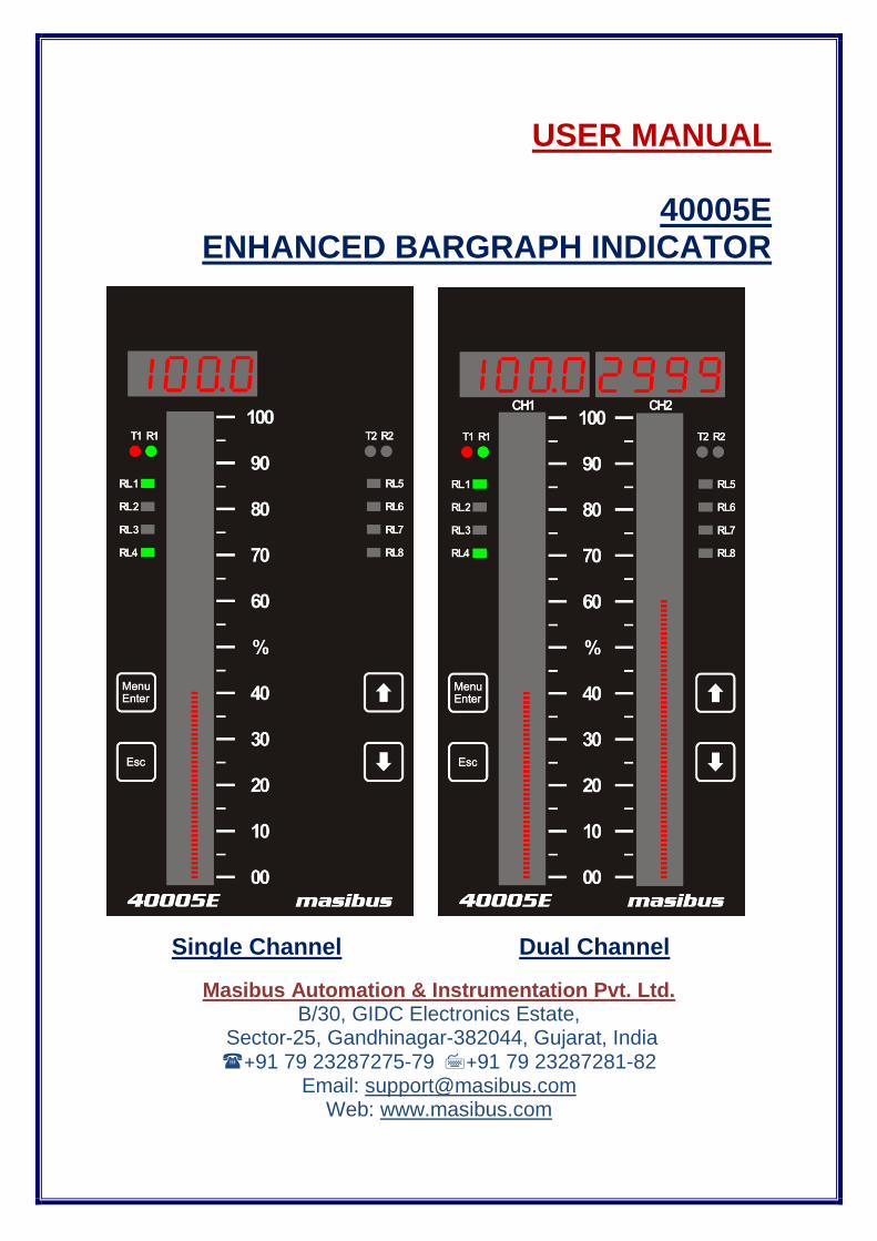
USER MANUAL
40005E
ENHANCED BARGRAPH INDICATOR
Single Channel Dual Channel
Masibus Automation & Instrumentation Pvt. Ltd. B/30, GIDC Electronics Estate,
Sector-25, Gandhinagar-382044, Gujarat, India +91 79 23287275-79 +91 79 23287281-82
Email: [email protected] Web: www.masibus.com
User Manual 2
40005E (Enhanced Bargraph Indicator) REF NO: m42B/om/101 Issue No: 02
CONTENTS
CONTENTS............................................................................................................................................. 2
LIST OF TABLES ................................................................................................................................... 3
LIST OF FIGURES ................................................................................................................................. 4
SAFETY PRECAUTIONS ................................................................................................................ 5
DESCRIPTION OF SIGNS ............................................................................................................... 5
1. INTRODUCTION ............................................................................................................................... 6 Foreword ........................................................................................................................................... 6 Notice ................................................................................................................................................ 6 Trademarks ....................................................................................................................................... 6 Version Number : 01A_151503, November 2015. .......................................................................... 6 Checking the Contents of the Package ............................................................................................ 6 1.1 Product Ordering Code ............................................................................................................. 7
2. INSTALLATION ................................................................................................................................ 9 2.1 Safety Precautions in Installation ............................................................................................. 9 2.2 Mounting of 40005E ............................................................................................................... 10 2.3 Maintenance and Inspection ................................................................................................... 11
3. HARDWARE SPECIFICATION ...................................................................................................... 13 3.1 Input Specification .................................................................................................................. 13 3.2 Output Specification ................................................................................................................ 13 3.2.1 Digital Output- Relay ........................................................................................................... 13 3.2.2 Analog Output- Retransmission Output(Optional) ............................................................... 14 3.2.3 Isolated Transmit Power Supply .......................................................................................... 14 3.3 Programming and Setting ....................................................................................................... 14 3.4 Communication Specification ................................................................................................. 14 3.5 Network Connectivity (Optional) ............................................................................................. 14 3.6 Data logging (Optional) ............................................................................................................. 14 3.7 Display Specification .............................................................................................................. 15 3.8 Power Supply Specification .................................................................................................... 15 3.10 Signal Isolations And Insulation Specification ...................................................................... 15 3.11 Construction, Installation, and Wiring Specification ............................................................. 15 3.12 Environmental Specification ................................................................................................. 16
4. FRONT AND REAR PANEL DIAGRAM ........................................................................................ 17 4.1 Front Panel Diagram .............................................................................................................. 17 4.2 Key Function Description ........................................................................................................ 18 4.3 Rear Panel Diagram ............................................................................................................... 18
5. CONNECTION DIAGRAM .............................................................................................................. 19 5.1 Connection Terminal Details .................................................................................................. 19 5.2 Cable Details .......................................................................................................................... 21
6. BRIEF OPERATING PROCEDURE ............................................................................................... 27
7. MENU LAYOUT .............................................................................................................................. 28 7.1 Parameter Flow Diagram ........................................................................................................ 28 7.2 Menu Parameters- In Detail .................................................................................................... 32
8. ALARM OUTPUT, CONTROL OUTPUT , DIGITAL OUTPUT AND WATCHDOG OUTPUT OPERATION ......................................................................................................................................... 48
8.1 Alarm Output Operation ............................................................................................................ 48 8.2 Control Output Operation ........................................................................................................ 50 8.3 Basic DO(Digital Output) Function .......................................................................................... 50 8.4 Watchdog Timer(WDT) / Watchdog Output Operation .......................................................... 51
9. CALIBRATION PROCEDURE ....................................................................................................... 52
10. MODBUS COMMUNICATION DETAIL ........................................................................................ 54 10.1 Overview ............................................................................................................................... 54
User Manual 3
40005E (Enhanced Bargraph Indicator) REF NO: m42B/om/101 Issue No:02
10.2 Exception Responses ........................................................................................................... 55 10.3 Modbus Addresses ............................................................................................................... 56
11. TROUBLESHOOTING ................................................................................................................... 65
APPENDIX – A PV STATUS DURING SENSOR BURN OUT CONDITIONS .................................... 66
APPENDIX – B HOW TO FETCH HISTORICAL DATA? .................................................................... 68
REVISION HISTORY : .......................................................................................................................... 71
LIST OF TABLES
Table 1 Product Ordering code ............................................................................................................... 7 Table 2 Product Ordering Code description ............................................................................................ 8 Table 3 Cable Ordering Code and description........................................................................................ 8 Table 4 Input types, their ranges, accuracy and resolution .................................................................. 13 Table 5 Signal Isolation Specification ................................................................................................... 15 Table 6 Pin Details of Relay Cable ....................................................................................................... 22 Table 7 Pin Details of Analog Input Output Cable ................................................................................ 24 Table 8 Program Mode Parameters ...................................................................................................... 33 Table 9 Configuration Mode Parameters .............................................................................................. 34 Table 10 Sub Parameters of Input Configuration Mode ....................................................................... 34 Table 11 Input Type Selection .............................................................................................................. 36 Table 12 10 – point Linearization .......................................................................................................... 36 Table 13 5 - Point Linearization ............................................................................................................ 37 Table 14 Sub Parameters of DO(Digital Output) Configuration Mode .................................................. 38 Table 15 DO(Digital Output) Mapping Number and its description....................................................... 39 Table 16 DO(Digital Output) description ............................................................................................... 41 Table 17 Sub Parameters of AO(Analog Output) Configuration Mode ................................................. 41 Table 18 AO(Analog Output)(Retransmission Output) description ....................................................... 42 Table 19 Sub Parameters of Communication Configuration Mode ...................................................... 42 Table 20 Sub Parameters of Display Configuration Mode .................................................................... 43 Table 21Sub Parameters of Logging Configuration Mode .................................................................... 43 Table 22 Calibration Mode Parameters ................................................................................................ 45 Table 23 Security Mode Parameters .................................................................................................... 46 Table 24 Factory Reset Menu ............................................................................................................... 46 Table 25 Alarm 1 and Alarm 2 Momentary Alarm Logic ....................................................................... 48 Table 26 Alarm 1 and Alarm 2 Maintained Alarm Logic ....................................................................... 49 Table 27 Control Operation(Optional) ................................................................................................... 50 Table 28 Error Messages and its Description ....................................................................................... 51 Table 29 Group Calibration Detail ......................................................................................................... 52 Table 30 Modbus Communication frame format ................................................................................... 54 Table 31 Modbus Function code description ........................................................................................ 55 Table 32 Modbus Query frame format .................................................................................................. 55 Table 33 Exceptional Response ........................................................................................................... 56 Table 34 Exception codes ..................................................................................................................... 56 Table 35 Process Value and Status Read Parameters ........................................................................ 56 Table 36 Details of abnormal Conditions of Process Value .................................................................. 57 Table 37 DO (Digital Output) Status Register and its bits arrangement ............................................... 57 Table 38 Alarm 1 Status Register and its bits arrangement ................................................................. 57 Table 39 Alarm 2 Status Register and its bits arrangement ................................................................. 57 Table 40 Other Status Registers ........................................................................................................... 57 Table 41 Holding Registers Parameters – Part 1 ................................................................................. 58 Table 42 Holding Registers Parameters – Part 2 ................................................................................. 58 Table 43 Holding Registers Parameters – Part 3 and Calibration Registers Parameters .................... 60 Table 44 Input Type Selection Table .................................................................................................... 61 Table 45 Bit accessible Holding Register Parameter – Square Root ................................................... 62
User Manual 4
40005E (Enhanced Bargraph Indicator) REF NO: m42B/om/101 Issue No: 02
Table 46 Bit accessible Holding Register Parameter – Others ............................................................. 62 Table 47 Parameter Applicability Selection ......................................................................................... 63 Table 48 CJC Selection ........................................................................................................................ 63 Table 49 Open Sensor Selection .......................................................................................................... 63 Table 50 Alarm Latch Selection ............................................................................................................ 63 Table 51 DO (Digital Output) Logic Selection ....................................................................................... 63 Table 52 Set Point Function Selection .................................................................................................. 63 Table 53 Set Point Type Selection ........................................................................................................ 63 Table 54 Retransmission Type Selection ............................................................................................. 63 Table 55 Retransmission Direction Selection ....................................................................................... 63 Table 56 Retransmission Value Selection ............................................................................................ 63 Table 57 COM Port Baud Rate Selection ............................................................................................. 63 Table 58 COM Parity Selection ............................................................................................................. 63 Table 59 Logging Enable Selection ...................................................................................................... 64 Table 60 Log Mode Selection……………………………………………………………………………… .. 64 Table 61 Factory Reset Parameters ..................................................................................................... 64 Table 62 WatchDog Output................................................................................................................... 64 Table 63 PV Status during Burn Out Condition .................................................................................... 66 Table 64 Retransmission Output during Open/Over/Under Condition ................................................. 67
LIST OF FIGURES
Figure 1 Panel Cutout Dimensions ....................................................................................................... 10 Figure 2 Side View and TOP view ........................................................................................................ 11 Figure 3 Front Panel Diagram for Dual Channel................................................................................... 17 Figure 4 Rear Panel Diagram …................ .......................................................................................... 18 Figure 5 Rear Panel Diagram……………………………………………………………………………….. . 18 Figure 6 Connection Terminals ............................................................................................................. 19 Figure 7 Relay Cable Connection ......................................................................................................... 21 Figure 8 Analog Input Output Cable Connection .................................................................................. 23 Figure 9 Back Plate Wiring Details ....................................................................................................... 25 Figure 10 Communication Cable Connections ..................................................................................... 26 Figure 11 Functional Block Diagram of 40005E ................................................................................... 27 Figure 12 Program Mode Flow diagram ............................................................................................... 28 Figure 13 Configuration Mode Flow diagram ........................................................................................ 29 Figure 14 Configuration Mode Flow diagram ........................................................................................ 30 Figure 15 Calibration Mode and Security Mode Flow diagram ............................................................. 31 Figure 16 Basic DO(Digital Output) Function........................................................................................ 50 Figure 17 The Query-Response Cycle ................................................................................................ 54

User Manual 5
40005E (Enhanced Bargraph Indicator) REF NO: m42B/om/101 Issue No:02
SAFETY PRECAUTIONS
The product and the instruction manual describe important information to prevent possible harm to users and damage to the property and to use the product safely. Understand the following description (signs and symbols), read the text and observe Descriptions.
DESCRIPTION OF SIGNS
This indicates a danger that may result in death or serious injury if not avoided.
This indicates a danger that may result in minor or moderate injury or only a physical damage if not avoided.

User Manual 6
40005E (Enhanced Bargraph Indicator) REF NO: m42B/om/101 Issue No: 02
1. INTRODUCTION
Foreword
Thank you for purchasing 40005E (Enhanced Bargraph Indicator). This manual describes the basic functions and operation methods of 40005E. Please read through this user‟s manual carefully before using the product. This is a 32 bit controller based instrument designed for universal input type. This instrument is operated by eight user-friendly keys. These keys are used for operation and programming. The manual covers all aspects of operation of the instrument. Please read instructions carefully before altering any programming or configuration information. The 40005E module operates independently and can also be connected to a data Highway for remote systems communication functions through a personal computer or a distributed control system (DCS) using RS 485 or Ethernet communication.
Notice
The contents of this manual are subject to change without notice as a result of continual improvements to the instrument‟s performance and functions. Every effort has been made to ensure accuracy in the preparation of this manual. Should any errors or omissions come to your attention, however, please inform Masibus Sales office or sales representative. Under no circumstances may the contents of this manual, in part or in whole, be transcribed or copied without our permission.
Trademarks
Our product names or brand names mentioned in this manual are the trademarks or registered trademarks of Masibus Automation and instrumentation Pvt. Ltd. Adobe, Acrobat, and Postscript are either registered trademarks or trademarks of Adobe Systems Incorporated. All other product names mentioned in this user's manual are trademarks or registered trademarks of their respective companies.
Version Number : 1.01, November 2015.
Checking the Contents of the Package
Unpack the box and check the contents before using the product. If the product is different from which you have ordered, if any parts or accessories are missing, or if the product appears to be damaged, contact your sales representative.
User Manual 7
40005E (Enhanced Bargraph Indicator) REF NO: m42B/om/101 Issue No:02
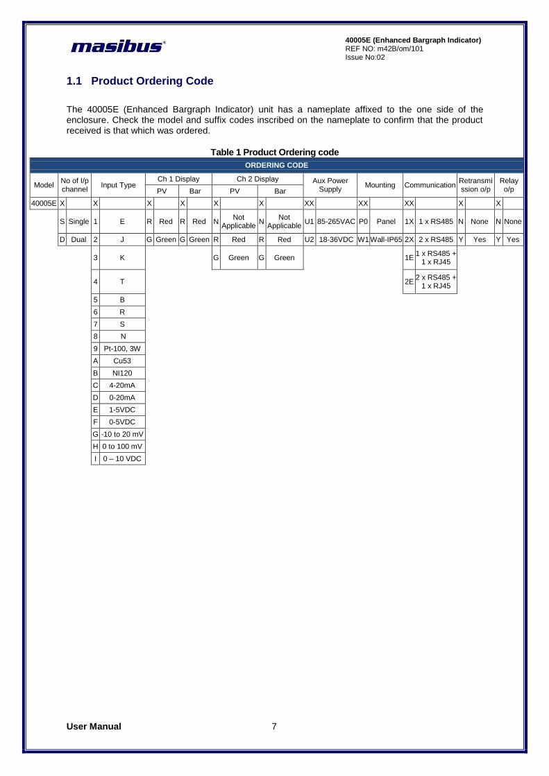
1.1 Product Ordering Code
The 40005E (Enhanced Bargraph Indicator) unit has a nameplate affixed to the one side of the enclosure. Check the model and suffix codes inscribed on the nameplate to confirm that the product received is that which was ordered.
Table 1 Product Ordering code
ORDERING CODE
Model No of I/p channel
Input Type Ch 1 Display Ch 2 Display Aux Power
Supply Mounting Communication
Retransmission o/p
Relay o/p PV Bar PV Bar
40005E X X X X X X XX XX XX X X
S Single 1 E R Red R Red N
Not Applicable
N Not
Applicable U1 85-265VAC P0 Panel 1X 1 x RS485 N None N None
D Dual 2 J G Green G Green R Red R Red U2 18-36VDC W1 Wall-IP65 2X 2 x RS485 Y Yes Y Yes
3 K
G Green G Green
1E
1 x RS485 + 1 x RJ45
4 T
2E
2 x RS485 + 1 x RJ45
5 B
6 R
7 S
8 N
9 Pt-100, 3W
A Cu53
B NI120
C 4-20mA
D 0-20mA
E 1-5VDC
F 0-5VDC
G -10 to 20 mV
H 0 to 100 mV
I 0 – 10 VDC
User Manual 8
40005E (Enhanced Bargraph Indicator) REF NO: m42B/om/101 Issue No: 02
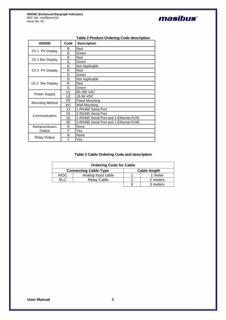
Table 2 Product Ordering Code description
40005E Code Description
Ch 1 PV Display R Red
G Green
Ch 1 Bar Display R Red
G Green
Ch 2 PV Display
N Not Applicable
R Red
G Green
Ch 2 Bar Display
N Not Applicable
R Red
G Green
Power Supply U1 85-265 VAC
U2 18-36 VDC
Mounting Method P0 Panel Mounting
W1 Wall Mounting
Communication
1X 1-RS485 Serial Port
2X 2-RS485 Serial Port
1E 1-RS485 Serial Port and 1-Ethernet RJ45
2E 2-RS485 Serial Port and 1-Ethernet RJ45
Retransmission Output
N None
Y Yes
Relay Output N None
Y Yes
Table 3 Cable Ordering Code and description
Ordering Code for Cable
Connecting Cable Type Cable length
AIOC Analog Input cable 1 1 meter
RLC Relay Cable 2 2 meters
3 3 meters

User Manual 9
40005E (Enhanced Bargraph Indicator) REF NO: m42B/om/101 Issue No:02
2. INSTALLATION
2.1 Safety Precautions in Installation
1. Before any other connection is made, the protective earth terminal shall be connected to a protective conductor. The mains (supply voltage) wiring must be terminated within the connector in such a way that, should it slip in the cable clamp, the Earth wire would be the last wire to become disconnected. The protective conductor terminal is marked with a label on the product bearing the following Symbol:
To connect the protective conductor terminal to earth, complete these steps: 1) Use a spade lug to make contact with the metal surface of the 40005E. 2) Use a green and yellow wire to reliably earth the protective conductor terminal. Wire gauge
must be no thinner than the current-carrying wire in the product‟s mains supply. 3) Resistance between the protective conductor terminal and earth must be no greater than
0.1 ohms. Use thicker gauge wire if the resistance is too high.
2. Do not use this instrument in areas under hazardous conditions such as excessive shock, vibration, dirt, moisture, corrosive gases or oil. The ambient temperature of the areas should not exceed the maximum rating specified.
3. To minimize the possibility of fire or shock hazards, do not expose this instrument to rain or excessive moisture.
Be sure all personnel involved in installation, servicing, and programming are qualified and familiar with electrical equipment and their ratings. Do not install, store, or use it in the place with a lot of dust, corrosive and flammable gases, vibrations and shocks exceeding the allowed values, place low or high temperature outside of the installation condition, direct sunlight and near equipment generating strong radio waves or magnetic fields, It may cause accidents.
User Manual 10
40005E (Enhanced Bargraph Indicator) REF NO: m42B/om/101 Issue No: 02
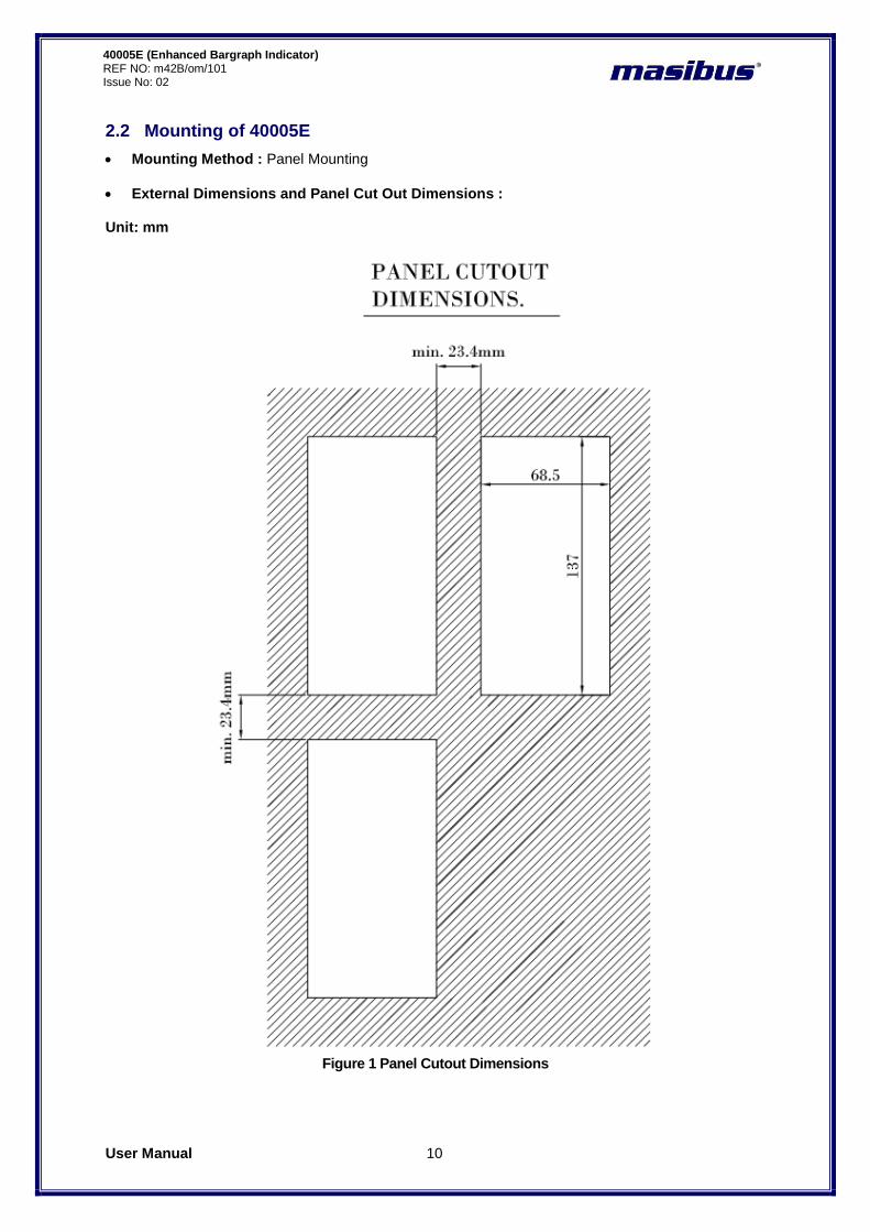
2.2 Mounting of 40005E
Mounting Method : Panel Mounting
External Dimensions and Panel Cut Out Dimensions : Unit: mm
Figure 1 Panel Cutout Dimensions
User Manual 11
40005E (Enhanced Bargraph Indicator) REF NO: m42B/om/101 Issue No:02
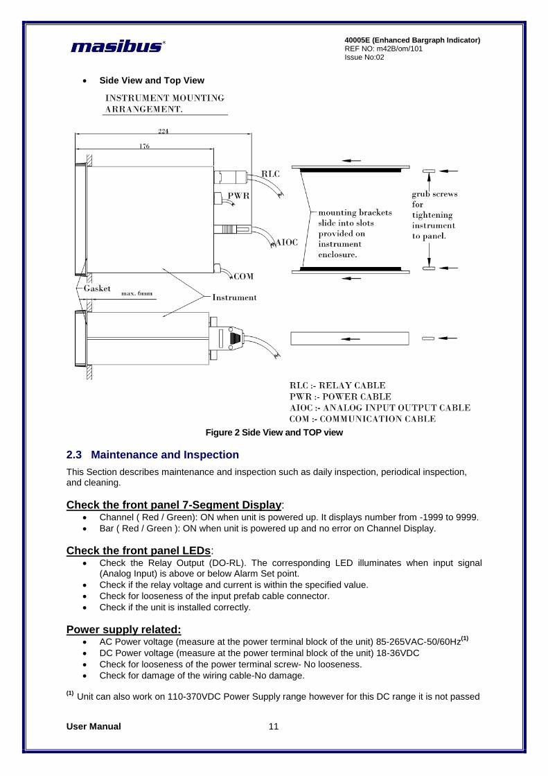
Side View and Top View
Figure 2 Side View and TOP view
2.3 Maintenance and Inspection
This Section describes maintenance and inspection such as daily inspection, periodical inspection, and cleaning.
Check the front panel 7-Segment Display: Channel ( Red / Green): ON when unit is powered up. It displays number from -1999 to 9999.
Bar ( Red / Green ): ON when unit is powered up and no error on Channel Display.
Check the front panel LEDs: Check the Relay Output (DO-RL). The corresponding LED illuminates when input signal
(Analog Input) is above or below Alarm Set point.
Check if the relay voltage and current is within the specified value.
Check for looseness of the input prefab cable connector.
Check if the unit is installed correctly.
Power supply related: AC Power voltage (measure at the power terminal block of the unit) 85-265VAC-50/60Hz
(1)
DC Power voltage (measure at the power terminal block of the unit) 18-36VDC
Check for looseness of the power terminal screw- No looseness.
Check for damage of the wiring cable-No damage. (1)
Unit can also work on 110-370VDC Power Supply range however for this DC range it is not passed

User Manual 12
40005E (Enhanced Bargraph Indicator) REF NO: m42B/om/101 Issue No: 02
through compliance tests.
Installation state: Check for looseness of the cable connector and damage of the cable-No looseness or damage.
Ambient environment: Check if the temperature and humidity are within the specified values.
User Manual 13
40005E (Enhanced Bargraph Indicator) REF NO: m42B/om/101 Issue No:02
3. HARDWARE SPECIFICATION
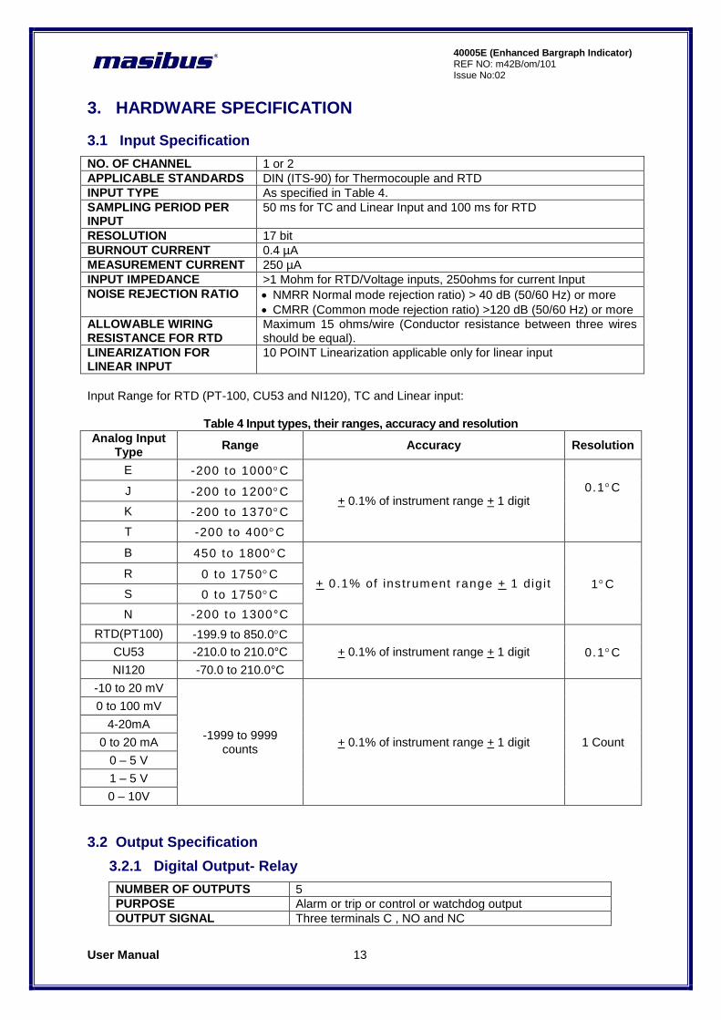
3.1 Input Specification
NO. OF CHANNEL 1 or 2
APPLICABLE STANDARDS DIN (ITS-90) for Thermocouple and RTD
INPUT TYPE As specified in Table 4.
SAMPLING PERIOD PER INPUT
50 ms for TC and Linear Input and 100 ms for RTD
RESOLUTION 17 bit
BURNOUT CURRENT 0.4 µA
MEASUREMENT CURRENT 250 µA
INPUT IMPEDANCE >1 Mohm for RTD/Voltage inputs, 250ohms for current Input
NOISE REJECTION RATIO NMRR Normal mode rejection ratio) > 40 dB (50/60 Hz) or more
CMRR (Common mode rejection ratio) >120 dB (50/60 Hz) or more
ALLOWABLE WIRING RESISTANCE FOR RTD
Maximum 15 ohms/wire (Conductor resistance between three wires should be equal).
LINEARIZATION FOR LINEAR INPUT
10 POINT Linearization applicable only for linear input
Input Range for RTD (PT-100, CU53 and NI120), TC and Linear input:
Table 4 Input types, their ranges, accuracy and resolution
Analog Input Type
Range Accuracy Resolution
E -200 to 1000C
+ 0.1% of instrument range + 1 digit
0.1C
J -200 to 1200C
K -200 to 1370C
T -200 to 400C
B 450 to 1800C
+ 0.1% of ins trument range + 1 dig it 1C R 0 to 1750C
S 0 to 1750C
N -200 to 1300°C
RTD(PT100) -199.9 to 850.0C
+ 0.1% of instrument range + 1 digit 0.1C CU53 -210.0 to 210.0°C
NI120 -70.0 to 210.0°C
-10 to 20 mV
-1999 to 9999 counts
+ 0.1% of instrument range + 1 digit 1 Count
0 to 100 mV
4-20mA
0 to 20 mA
0 – 5 V
1 – 5 V
0 – 10V
3.2 Output Specification
3.2.1 Digital Output- Relay
NUMBER OF OUTPUTS 5
PURPOSE Alarm or trip or control or watchdog output
OUTPUT SIGNAL Three terminals C , NO and NC
User Manual 14
40005E (Enhanced Bargraph Indicator) REF NO: m42B/om/101 Issue No: 02
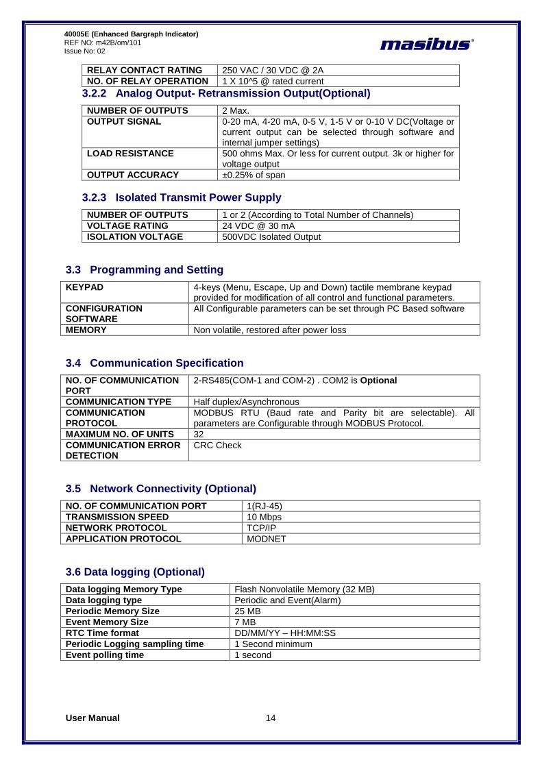
RELAY CONTACT RATING 250 VAC / 30 VDC @ 2A
NO. OF RELAY OPERATION 1 X 10^5 @ rated current
3.2.2 Analog Output- Retransmission Output(Optional)
NUMBER OF OUTPUTS 2 Max.
OUTPUT SIGNAL 0-20 mA, 4-20 mA, 0-5 V, 1-5 V or 0-10 V DC(Voltage or current output can be selected through software and internal jumper settings)
LOAD RESISTANCE 500 ohms Max. Or less for current output. 3k or higher for voltage output
OUTPUT ACCURACY ±0.25% of span
3.2.3 Isolated Transmit Power Supply
NUMBER OF OUTPUTS 1 or 2 (According to Total Number of Channels)
VOLTAGE RATING 24 VDC @ 30 mA
ISOLATION VOLTAGE 500VDC Isolated Output
3.3 Programming and Setting
KEYPAD 4-keys (Menu, Escape, Up and Down) tactile membrane keypad provided for modification of all control and functional parameters.
CONFIGURATION SOFTWARE
All Configurable parameters can be set through PC Based software
MEMORY Non volatile, restored after power loss
3.4 Communication Specification
NO. OF COMMUNICATION PORT
2-RS485(COM-1 and COM-2) . COM2 is Optional
COMMUNICATION TYPE Half duplex/Asynchronous
COMMUNICATION PROTOCOL
MODBUS RTU (Baud rate and Parity bit are selectable). All parameters are Configurable through MODBUS Protocol.
MAXIMUM NO. OF UNITS 32
COMMUNICATION ERROR DETECTION
CRC Check
3.5 Network Connectivity (Optional)
NO. OF COMMUNICATION PORT 1(RJ-45)
TRANSMISSION SPEED 10 Mbps
NETWORK PROTOCOL TCP/IP
APPLICATION PROTOCOL MODNET
3.6 Data logging (Optional)
Data logging Memory Type Flash Nonvolatile Memory (32 MB)
Data logging type Periodic and Event(Alarm)
Periodic Memory Size 25 MB
Event Memory Size 7 MB
RTC Time format DD/MM/YY – HH:MM:SS
Periodic Logging sampling time 1 Second minimum
Event polling time 1 second

User Manual 15
40005E (Enhanced Bargraph Indicator) REF NO: m42B/om/101 Issue No:02
3.7 Display Specification
CHANNEL DATA DISPLAY
Ch- 1 : 4-digits, 7-segment, Red / Green , 0.3‟‟ character height Ch- 2 : 4-digits, 7-segment, Red / Green , 0.3‟‟ character height
BAR DISPLAY Ch- 1 : 101 Segment Red / Green bar for indicating PV in percentage Ch- 2 : 101 Segment Red / Green bar for indicating PV in percentage
STATUS LEDs 8-Green LEDs for Relay status2-Green(Rx) & 2-Red(Tx) for Communication
3.8 Power Supply Specification
RATED VOLTAGE 85-265VAC-50/60Hz(1)
or 18-36VDC (Optional)
POWER CONSUMPTION Max. 16 VA (85-265 VAC) and Max. 8 VA (18-36 VDC)
(1)
Unit can also work on 110-370VDC Power Supply range however for this DC range it is not passed through compliance tests.
3.10 Signal Isolations And Insulation Specification
ISOLATION RATING Withstanding Voltage: 1) Between primary terminals
(1) and secondary terminals
(2):
1500VAC for 1 minute 2) Between secondary terminals: 500V AC for 1 minute
SIGNAL ISOLATION As specified in Table 5
INSULATION RESISTANCE > 20 Mohms at 500V DC
(1)
Primary terminals indicate power terminals and relay output terminals (2)
Secondary terminals indicate analog input signals, Digital Contact output terminals, communication terminals and Ethernet N/W terminal Signal Isolation Specifications:
Table 5 Signal Isolation Specification
Sr No
Signals Signal Isolation
1 Power Input Isolated from other input/output terminals and internal circuit
2 Analog Inputs Not isolated from other analog input terminals and from the internal circuit. But isolated from other input/output terminals.
3 RS-485 Communication Isolated from other input/output terminals and internal circuit
4 Ethernet Communication Isolated from other input/output terminals and internal circuit
5 Relay contacts Isolated between contact output terminals and from other Input/output terminals and internal circuit
6 Digital Output Isolated from other input/output terminals and internal circuit
3.11 Construction, Installation, and Wiring Specification
MATERIAL Aluminium extrusion
CONSTRUCTION Panel Mount Top and Bottom mounting clamps (1 each) Or Wall Mount
CASE COLOR Clear Anodized
WEIGHT 1.25 KG
ENCLOSURE DIMENSION 72mm (W) X 144mm (H) X 165mm (D)
PANEL CUTOUT 68.5mm (W) x 137mm (H)

User Manual 16
40005E (Enhanced Bargraph Indicator) REF NO: m42B/om/101 Issue No: 02
3.12 Environmental Specification
AMBIENT TEMPERATURE -10 to 55°C
HUMIDITY 30% to 95% RH (Non-Condensing)
TEMPERATURE COEFFICIENT For All Analog input circuits < 100ppm
WEIGHT 1.25 KG
INSTRUMENT WARM-UP TIME <15 minutes after power on
DEGREE OF PROTECTION IP54 (From Front)
User Manual 17
40005E (Enhanced Bargraph Indicator) REF NO: m42B/om/101 Issue No:02
4. FRONT AND REAR PANEL DIAGRAM
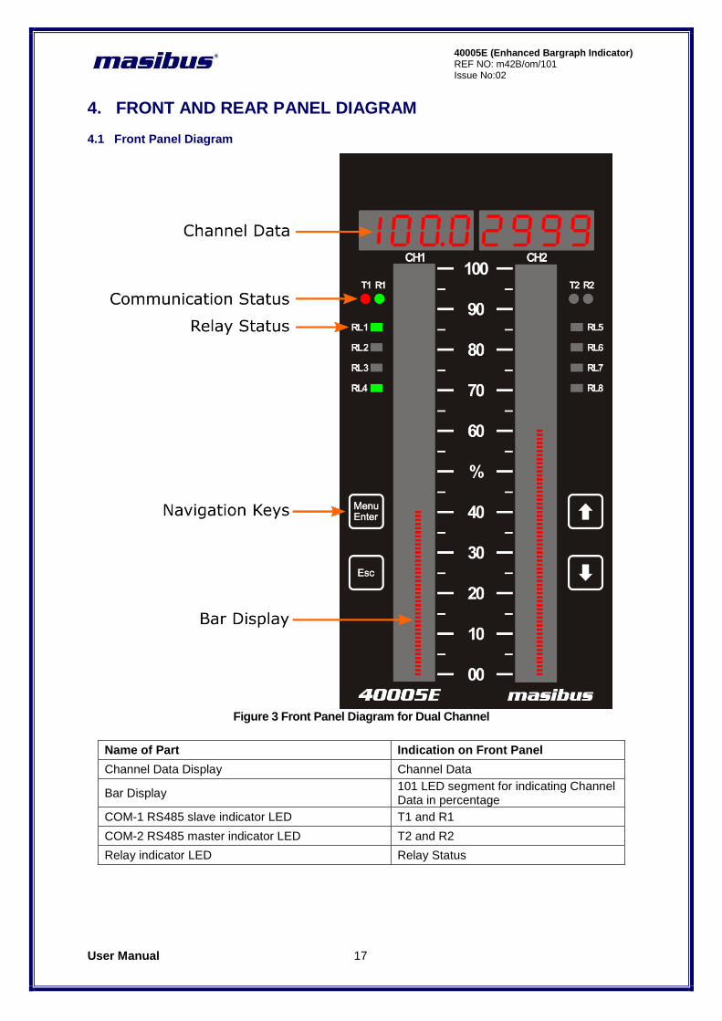
4.1 Front Panel Diagram
Figure 3 Front Panel Diagram for Dual Channel
Name of Part Indication on Front Panel
Channel Data Display Channel Data
Bar Display 101 LED segment for indicating Channel Data in percentage
COM-1 RS485 slave indicator LED T1 and R1
COM-2 RS485 master indicator LED T2 and R2
Relay indicator LED Relay Status
User Manual 18
40005E (Enhanced Bargraph Indicator) REF NO: m42B/om/101 Issue No: 02
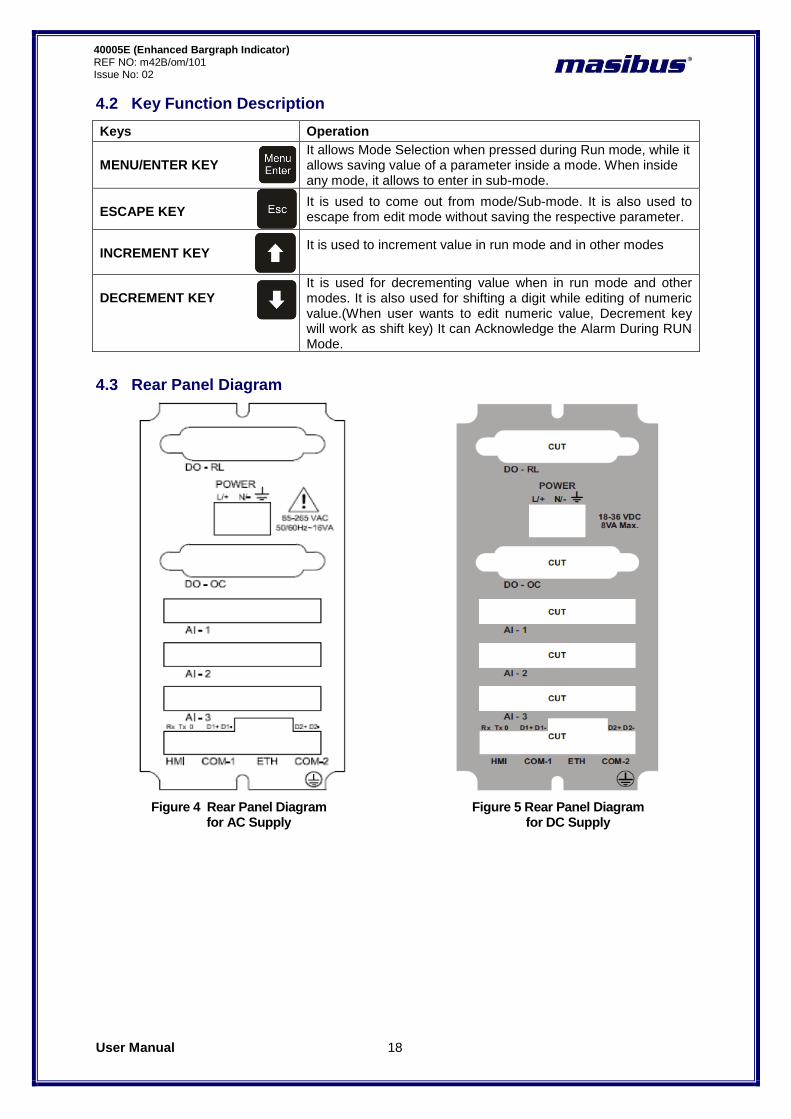
4.2 Key Function Description
Keys Operation
MENU/ENTER KEY
It allows Mode Selection when pressed during Run mode, while it allows saving value of a parameter inside a mode. When inside any mode, it allows to enter in sub-mode.
ESCAPE KEY
It is used to come out from mode/Sub-mode. It is also used to escape from edit mode without saving the respective parameter.
INCREMENT KEY
It is used to increment value in run mode and in other modes
DECREMENT KEY
It is used for decrementing value when in run mode and other modes. It is also used for shifting a digit while editing of numeric value.(When user wants to edit numeric value, Decrement key will work as shift key) It can Acknowledge the Alarm During RUN Mode.
4.3 Rear Panel Diagram
Figure 4 Rear Panel Diagram Figure 5 Rear Panel Diagram for AC Supply for DC Supply
User Manual 19
40005E (Enhanced Bargraph Indicator) REF NO: m42B/om/101 Issue No:02
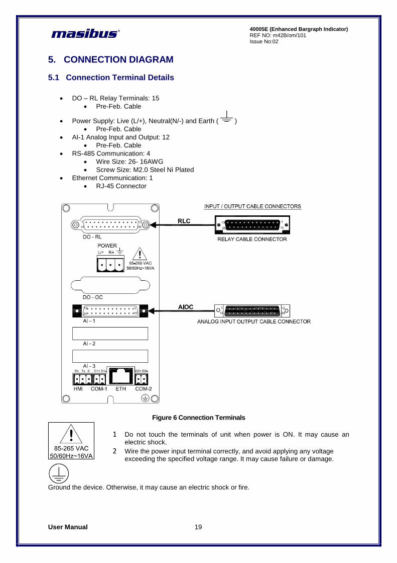
5. CONNECTION DIAGRAM
5.1 Connection Terminal Details
DO – RL Relay Terminals: 15
Pre-Feb. Cable
Power Supply: Live (L/+), Neutral(N/-) and Earth ( )
Pre-Feb. Cable
AI-1 Analog Input and Output: 12
Pre-Feb. Cable
RS-485 Communication: 4
Wire Size: 26- 16AWG
Screw Size: M2.0 Steel Ni Plated
Ethernet Communication: 1
RJ-45 Connector
Figure 6 Connection Terminals
1 Do not touch the terminals of unit when power is ON. It may cause an electric shock.
2 Wire the power input terminal correctly, and avoid applying any voltage exceeding the specified voltage range. It may cause failure or damage.
Ground the device. Otherwise, it may cause an electric shock or fire.

User Manual 20
40005E (Enhanced Bargraph Indicator) REF NO: m42B/om/101 Issue No: 02
Connect the protective conductor terminal to earth, Use a spade lug to make contact with the metal surface of the 40005E.
1 All wiring must confirm to appropriate standards of good practice and local codes and
regulations. Wiring must be suitable for Voltage, Current and temperature rating of the system.
2 Provide power from a single-phase instrument power supply. If there is a lot of noise in the power line, insert an insulating transformer into the primary side of the line and use a line filter on the secondary side. Do not place the primary and secondary power cables close to each other.
3 High voltage transients may occur when switching inductive loads such as some contactors. Through the internal contacts, these transients may introduce disturbances which could affect the performance of the instrument.
4 For this type of load it is highly recommended that a “snubber” is connected across the normally open contact of the relay switching through load. The recommended snubber consists of a series connected resistor/capacitor (typically 15nF/100Ohms). In addition a snubber will prolong the life of the relay contacts. A snubber should also be connected across a trick output to prevent false triggering under line transient conditions.
User Manual 21
40005E (Enhanced Bargraph Indicator) REF NO: m42B/om/101 Issue No:02
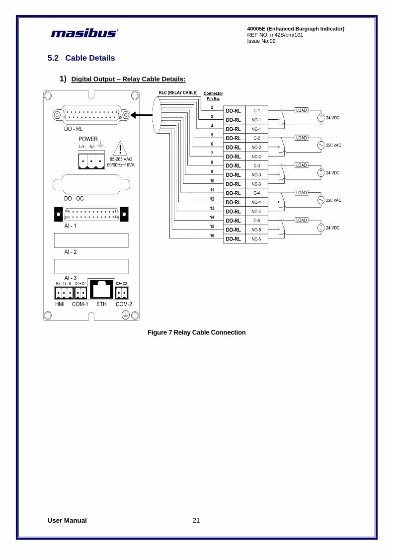
5.2 Cable Details
1) Digital Output – Relay Cable Details:
Figure 7 Relay Cable Connection
User Manual 22
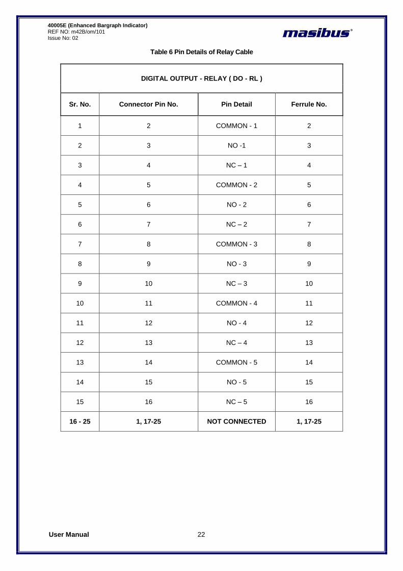
40005E (Enhanced Bargraph Indicator) REF NO: m42B/om/101 Issue No: 02
Table 6 Pin Details of Relay Cable
DIGITAL OUTPUT - RELAY ( DO - RL )
Sr. No. Connector Pin No. Pin Detail Ferrule No.
1 2 COMMON - 1 2
2 3 NO -1 3
3 4 NC – 1 4
4 5 COMMON - 2 5
5 6 NO - 2 6
6 7 NC – 2 7
7 8 COMMON - 3 8
8 9 NO - 3 9
9 10 NC – 3 10
10 11 COMMON - 4 11
11 12 NO - 4 12
12 13 NC – 4 13
13 14 COMMON - 5 14
14 15 NO - 5 15
15 16 NC – 5 16
16 - 25 1, 17-25 NOT CONNECTED 1, 17-25
User Manual 23
40005E (Enhanced Bargraph Indicator) REF NO: m42B/om/101 Issue No:02
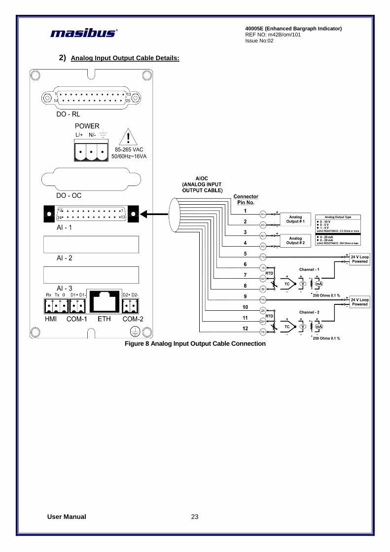
2) Analog Input Output Cable Details:
Figure 8 Analog Input Output Cable Connection
User Manual 24
40005E (Enhanced Bargraph Indicator) REF NO: m42B/om/101 Issue No: 02
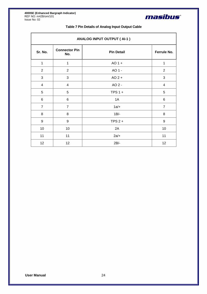
Table 7 Pin Details of Analog Input Output Cable
ANALOG INPUT OUTPUT ( AI-1 )
Sr. No. Connector Pin
No. Pin Detail Ferrule No.
1 1 AO 1 + 1
2 2 AO 1 - 2
3 3 AO 2 + 3
4 4 AO 2 - 4
5 5 TPS 1 + 5
6 6 1A 6
7 7 1a/+ 7
8 8 1B/- 8
9 9 TPS 2 + 9
10 10 2A 10
11 11 2a/+ 11
12 12 2B/- 12
User Manual 25
40005E (Enhanced Bargraph Indicator) REF NO: m42B/om/101 Issue No:02
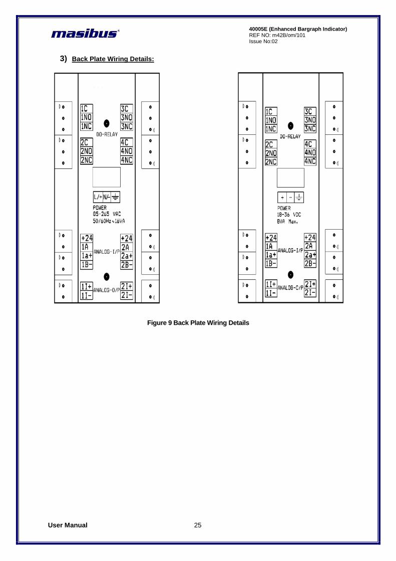
3) Back Plate Wiring Details:
Figure 9 Back Plate Wiring Details
User Manual 26
40005E (Enhanced Bargraph Indicator) REF NO: m42B/om/101 Issue No: 02
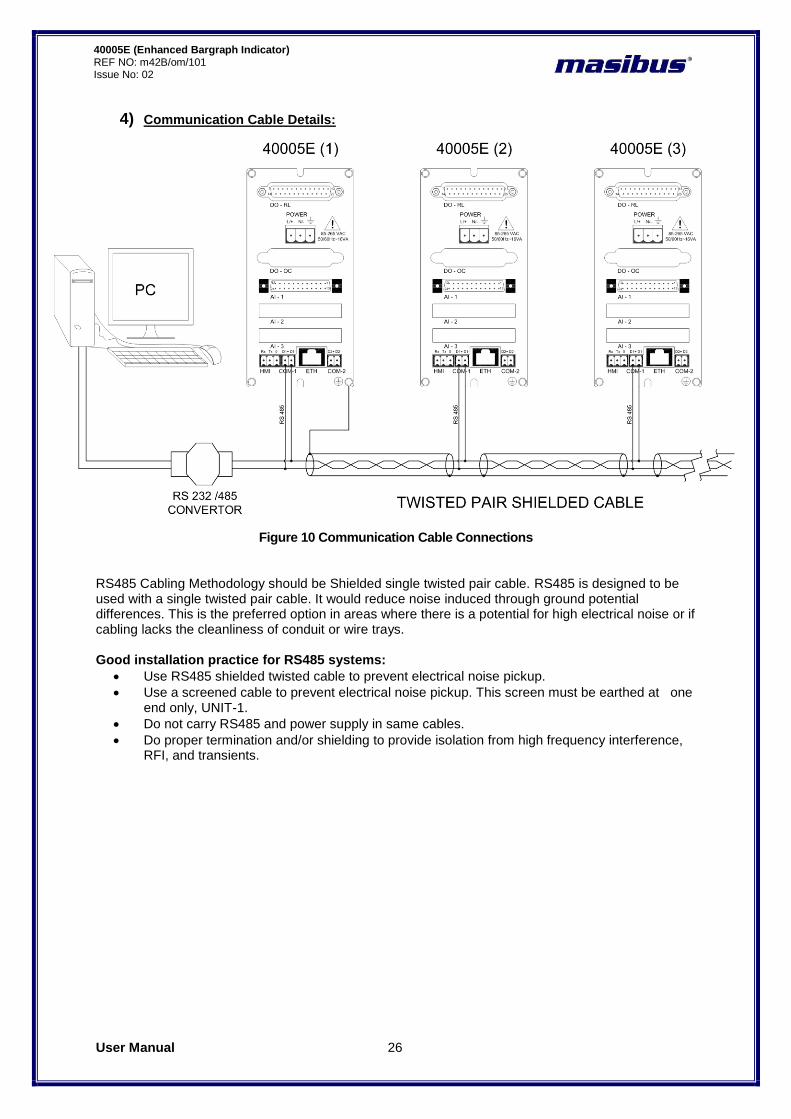
4) Communication Cable Details:
Figure 10 Communication Cable Connections RS485 Cabling Methodology should be Shielded single twisted pair cable. RS485 is designed to be used with a single twisted pair cable. It would reduce noise induced through ground potential differences. This is the preferred option in areas where there is a potential for high electrical noise or if cabling lacks the cleanliness of conduit or wire trays. Good installation practice for RS485 systems:
Use RS485 shielded twisted cable to prevent electrical noise pickup.
Use a screened cable to prevent electrical noise pickup. This screen must be earthed at one end only, UNIT-1.
Do not carry RS485 and power supply in same cables.
Do proper termination and/or shielding to provide isolation from high frequency interference, RFI, and transients.
User Manual 27
40005E (Enhanced Bargraph Indicator) REF NO: m42B/om/101 Issue No:02
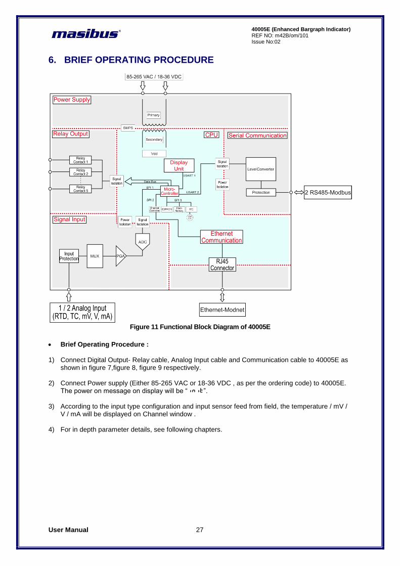
6. BRIEF OPERATING PROCEDURE
Figure 11 Functional Block Diagram of 40005E
Brief Operating Procedure : 1) Connect Digital Output- Relay cable, Analog Input cable and Communication cable to 40005E as
shown in figure 7,figure 8, figure 9 respectively.
2) Connect Power supply (Either 85-265 VAC or 18-36 VDC , as per the ordering code) to 40005E. The power on message on display will be “init”.
3) According to the input type configuration and input sensor feed from field, the temperature / mV /
V / mA will be displayed on Channel window . 4) For in depth parameter details, see following chapters.
User Manual 28
40005E (Enhanced Bargraph Indicator) REF NO: m42B/om/101 Issue No: 02
7. MENU LAYOUT
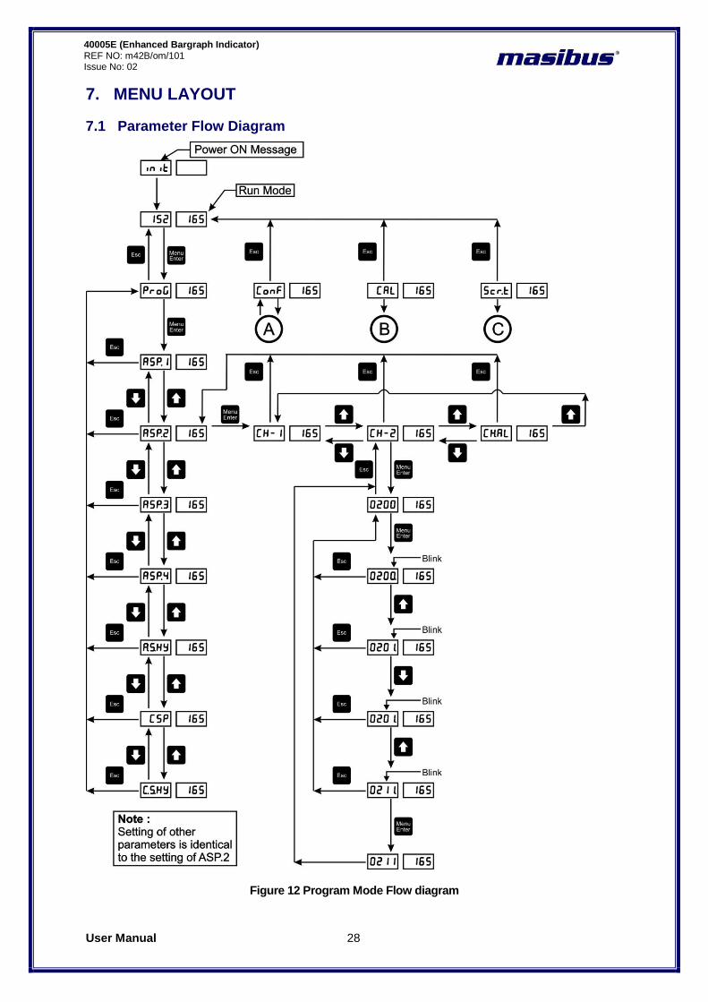
7.1 Parameter Flow Diagram
Figure 12 Program Mode Flow diagram
User Manual 29
40005E (Enhanced Bargraph Indicator) REF NO: m42B/om/101 Issue No:02
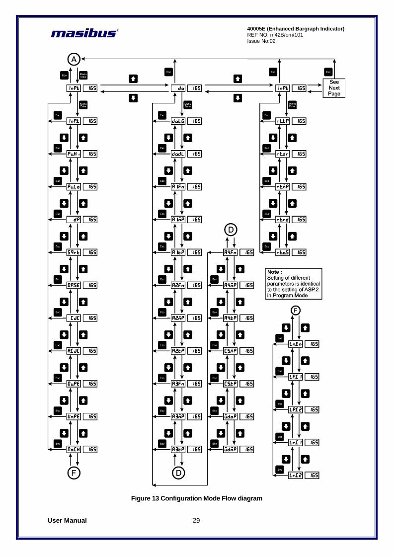
Figure 13 Configuration Mode Flow diagram

User Manual 30
40005E (Enhanced Bargraph Indicator) REF NO: m42B/om/101 Issue No: 02
Figure 14 Configuration Mode Flow diagram
User Manual 31
40005E (Enhanced Bargraph Indicator) REF NO: m42B/om/101 Issue No:02
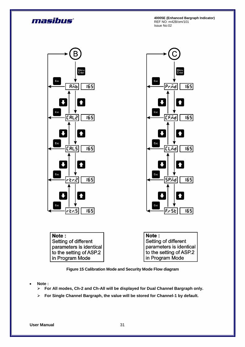
Figure 15 Calibration Mode and Security Mode Flow diagram
Note : For All modes, Ch-2 and Ch-All will be displayed for Dual Channel Bargraph only.
For Single Channel Bargraph, the value will be stored for Channel-1 by default.

User Manual 32
40005E (Enhanced Bargraph Indicator) REF NO: m42B/om/101 Issue No: 02
7.2 Menu Parameters- In Detail
Note : For All modes, Ch-2 and Ch-All will be displayed for Dual Channel Bargraph only.
For Single Channel Bargraph, the value will be stored for Channel-1 by default.
Run Mode : Following parameters can view or change during run time. Immediately after powering, unit will run in Auto Mode
By pressing Enter in run mode, the menu goes into the settings of main menu.
By pressing and holding Decrement Key in run mode, relay acknowledgement can be done.
Other Modes :
For entering in Menu press Menu/Enter key in RUN mode. There are total Four modes in Menu. By pressing increment or decrement key, mode can be changed. To enter into any mode press Menu/enter key again.
1. Program mode 2. Configuration mode 3. Calibration mode 4. Security Mode
The tables below show the description and menu detail of the all the modes. In general to enter into any menu Or to edit sub menu, press Menu/Enter key. To change the submenu parameter press increment or decrement key. To come out from any menu press Esc key.
1) Program Mode :
Pressing MENU key CHANNEL window shows Prog (Prog) message. Press MENU key again
CHANNEL window shows pWd (PWD) message(if and only if password is set other than zero , Otherwise it will enter into sub menu), press MENU Key to enter into edit mode of password and then press INCREMENT key or DECREMENT key to modify the password and then press MENU
Key to enter into Program Mode. CHANNEL window shows ASP.1 (ASP.1) message. By
pressing MENU Key, CHANNEL window shows CH-1 (CH-1) message. Means it is asking which channel value needs to be changed. By pressing MENU key again, CHANNEL window shows the ASP.1 value of channel number 1. Then use MENU Key to enter into editing mode and use INCREMENT and DECREMENT key to modify value for channel 1 . OR press ESCAPE key and then press INCREMENT key to change Set-point 1 for Channel 2. After pressing INC key many
times, the message on Channel Window shows CH.Al,(CH. AL) which means user can modify
parameters for all channels at once(AL = ALL). ESCAPE KEY is used to come out of ASP.1 setting.
User Manual 33
40005E (Enhanced Bargraph Indicator) REF NO: m42B/om/101 Issue No:02
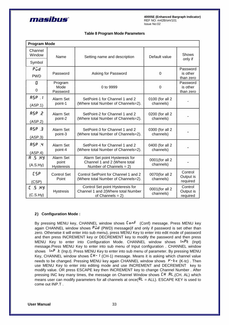
Table 8 Program Mode Parameters
Program Mode
Channel Window Name Setting name and description Default value
Shows only if
Symbol
PWD Password Asking for Password 0
Password is other
than zero PWD
0 Program Mode
Password 0 to 9999 0
Password is other
than zero 0
ASp.1 Alarm Set point-1
SetPoint-1 for Channel 1 and 2 (Where total Number of Channels=2).
0100 (for all 2 channels)
- (ASP.1)
aSP.2 Alarm Set point-2
SetPoint-2 for Channel 1 and 2 (Where total Number of Channels=2).
0200 (for all 2 channels)
-
(ASP.2)
aSP.3 Alarm Set point-3
SetPoint-3 for Channel 1 and 2 (Where total Number of Channels=2).
0300 (for all 2 channels)
-
(ASP.3)
aSP.4 Alarm Set point-4
SetPoint-4 for Channel 1 and 2 (Where total Number of Channels=2).
0400 (for all 2 channels)
-
(ASP.4)
a.s.Hy Alarm Set point
Hysteresis
Alarm Set point Hysteresis for Channel 1 and 2 (Where total
Number of Channels = 2)
0001(for all 2 channels)
- (A.S.Hy)
CSP Control Set Point
Control SetPoint for Channel 1 and 2 (Where total Number of Channels=2).
0070(for all 2 channels)
Control Output is required (CSP)
C.S.Hy Hystresis
Control Set point Hysteresis for Channel 1 and 2(Where total Number
of Channels = 2)
0001(for all 2 channels)
Control Output is required (C.S.Hy)
2) Configuration Mode :
By pressing MENU key, CHANNEL window shows Conf (Conf) message. Press MENU key
again CHANNEL window shows pWd (PWD) message(if and only if password is set other than zero. Otherwise it will enter into sub menu), press MENU Key to enter into edit mode of password and then press INCREMENT key or DECREMENT key to modify the password and then press
MENU Key to enter into Configuration Mode. CHANNEL window shows Inpt (Inpt) message.Press MENU Key to enter into sub menu of Input configuration . CHANNEL window
shows Inp.t (Inp.t). Press MENU Key to enter into sub menu of parameter. By pressing MENU
Key, CHANNEL window shows CH-1 (CH-1) message. Means it is asking which channel value
needs to be changed. Pressing MENU key again CHANNEL window shows K-tc (K-tc) . Then use MENU Key to enter into editing mode and use INCREMENT and DECREMENT key to modify value. OR press ESCAPE key then INCREMENT key to change Channel Number . After
pressing INC key many times, the message on Channel Window shows CH.Al,(CH. AL) which
means user can modify parameters for all channels at once(AL = ALL). ESCAPE KEY is used to come out INP.T .
User Manual 34
40005E (Enhanced Bargraph Indicator) REF NO: m42B/om/101 Issue No: 02
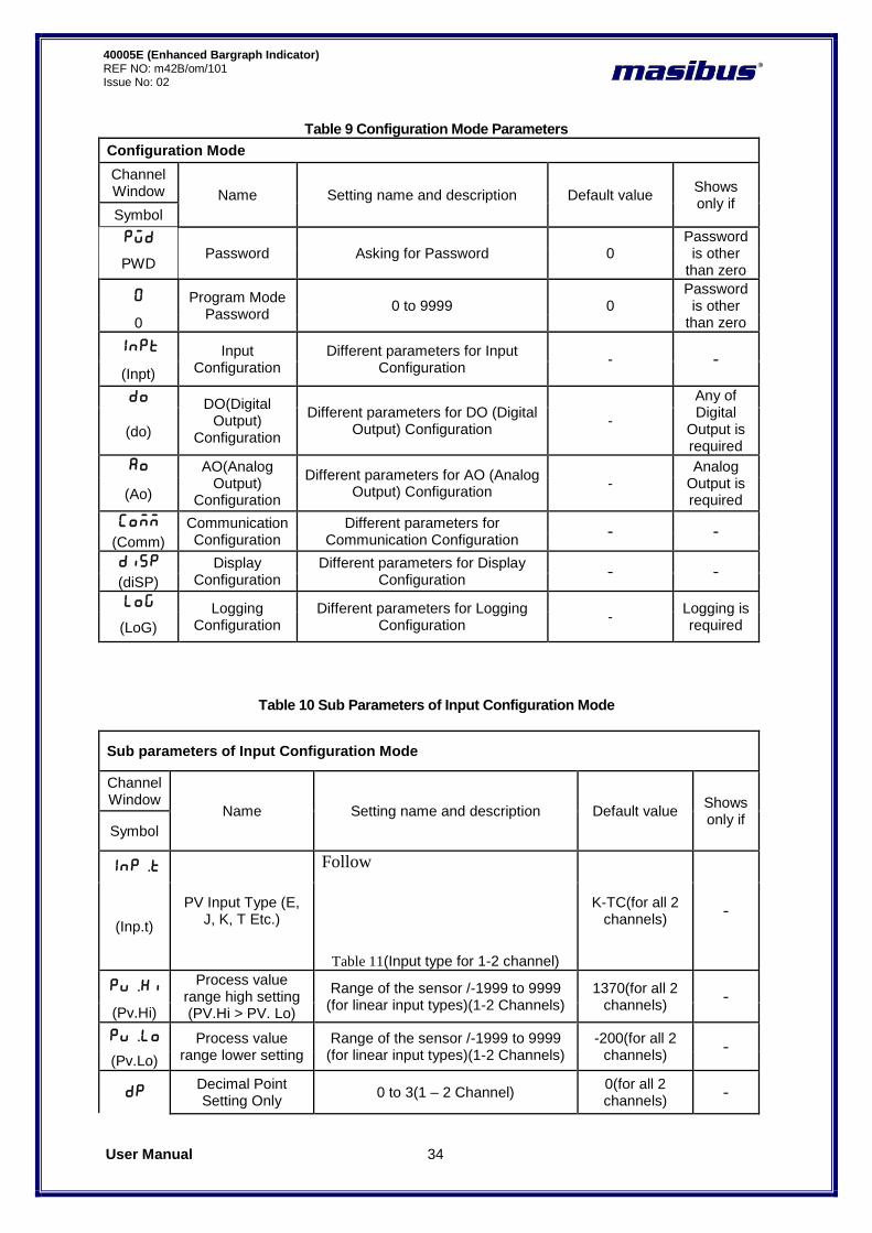
Table 9 Configuration Mode Parameters
Configuration Mode
Channel Window Name Setting name and description Default value
Shows only if
Symbol
PWD Password Asking for Password 0
Password is other
than zero PWD
0 Program Mode Password
0 to 9999 0 Password is other
than zero 0
Inpt Input Configuration
Different parameters for Input Configuration
- - (Inpt)
Do DO(Digital Output)
Configuration
Different parameters for DO (Digital Output) Configuration
-
Any of Digital
Output is required
(do)
Ao AO(Analog Output)
Configuration
Different parameters for AO (Analog Output) Configuration
- Analog
Output is required (Ao)
Comm Communication Configuration
Different parameters for Communication Configuration
- - (Comm)
Disp Display Configuration
Different parameters for Display Configuration
- - (diSP)
Log Logging Configuration
Different parameters for Logging Configuration
- Logging is required (LoG)
Table 10 Sub Parameters of Input Configuration Mode
Sub parameters of Input Configuration Mode
Channel Window
Name Setting name and description Default value Shows only if
Symbol
Inp.t
PV Input Type (E, J, K, T Etc.)
Follow
Table 11(Input type for 1-2 channel)
K-TC(for all 2 channels)
- (Inp.t)
pv.Hi Process value range high setting (PV.Hi > PV. Lo)
Range of the sensor /-1999 to 9999 (for linear input types)(1-2 Channels)
1370(for all 2 channels)
- (Pv.Hi)
pv.Lo Process value range lower setting
Range of the sensor /-1999 to 9999 (for linear input types)(1-2 Channels)
-200(for all 2 channels)
- (Pv.Lo)
Dp Decimal Point Setting Only
0 to 3(1 – 2 Channel) 0(for all 2 channels)
-
User Manual 35
40005E (Enhanced Bargraph Indicator) REF NO: m42B/om/101 Issue No:02
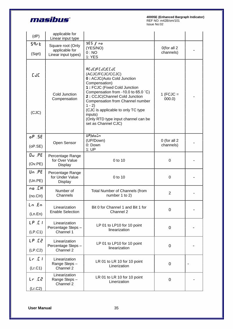
(dP) applicable for
Linear input type
Sqrt Square root (Only applicable for
Linear input types)
yes / no (YES/NO) 0 : NO 1: YES
0(for all 2 channels)
- (Sqrt)
CJC
Cold Junction Compensation
ACJC/FCjC/CCJC (ACJC/FCJC/CCJC) 0 : ACJC(Auto Cold Junction Compensation) 1 : FCJC (Fixed Cold Junction Compensation from -10.0 to 65.0 ˚C) 2 : CCJC(Channel Cold Junction Compensation from Channel number 1 - 2) (CJC is applicable to only TC type inputs) (Only RTD type input channel can be set as Channel CJC)
1 (FCJC = 000.0)
-
(CJC)
op.se Open Sensor
UP/Down (UP/Down) 0: Down 1: UP
0 (for all 2 channels)
- (oP.SE)
Ov.pe Percentage Range for Over Value
Display 0 to 10 0 -
(Ov.PE)
un.pe Percentage Range for Under Value
Display 0 to 10 0 -
(Un.PE)
no.CH Number of Channels
Total Number of Channels (from number 1 to 2)
2 - (no.CH)
Ln.En Linearization
Enable Selection Bit 0 for Channel 1 and Bit 1 for
Channel 2 0 -
(Ln.En)
Lp.C1 Linearization Percentage Steps –
Channel 1
LP 01 to LP10 for 10 point linearization
0 - (LP.C1)
Lp.C2 Linearization Percentage Steps –
Channel 2
LP 01 to LP10 for 10 point linearization
0 -
(LP.C2)
LR.C1 Linearization Range Steps –
Channel 2
LR 01 to LR 10 for 10 point Linerization
0 - (Lr.C1)
LR.C2
Linearization Range Steps –
Channel 2
LR 01 to LR 10 for 10 point Linerization
0 -
(Lr.C2)
User Manual 36
40005E (Enhanced Bargraph Indicator) REF NO: m42B/om/101 Issue No: 02
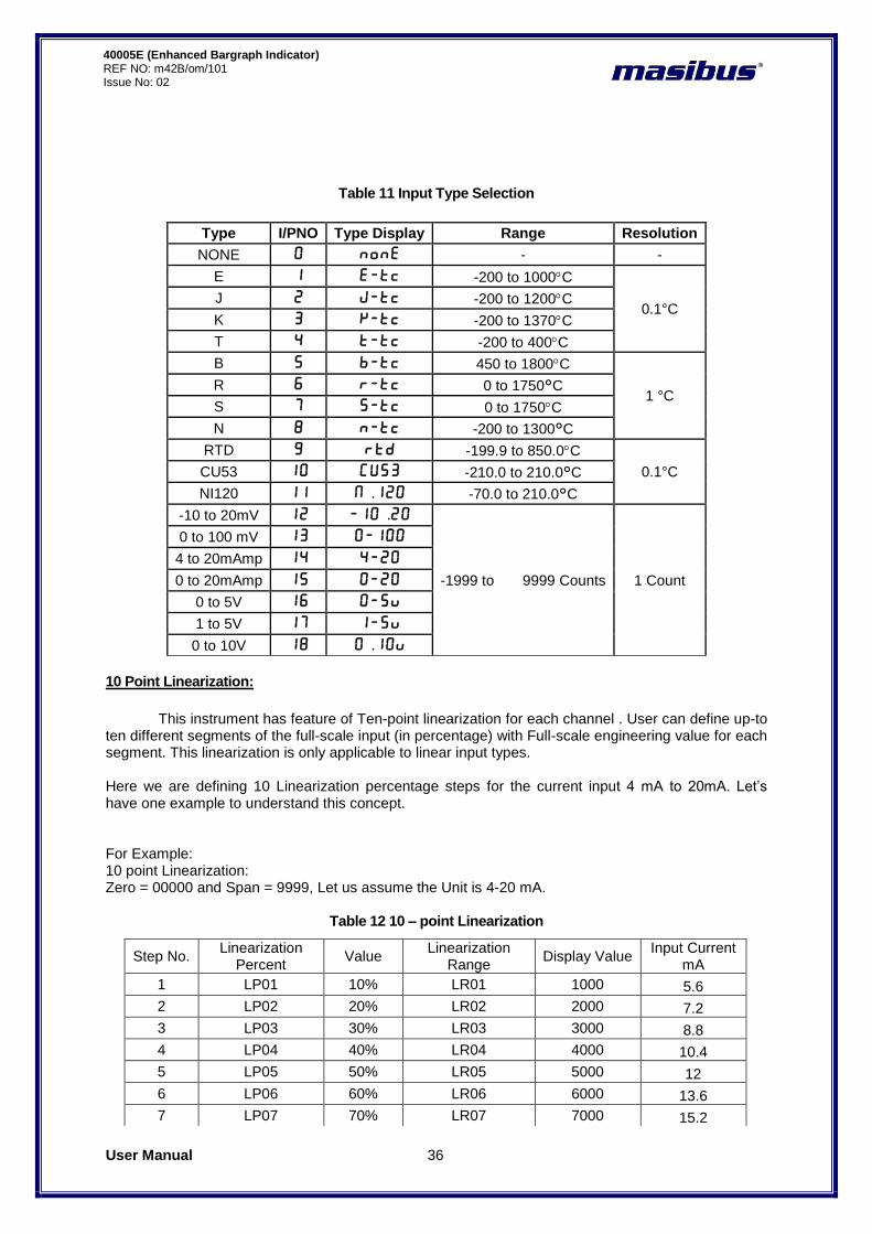
Table 11 Input Type Selection
Type I/PNO Type Display Range Resolution
NONE 0 none - -
E 1 E-Tc -200 to 1000C
0.1°C J 2 J-tc -200 to 1200C
K 3 K-tc -200 to 1370C
T 4 T-tc -200 to 400C
B 5 B-tc 450 to 1800C
1 °C R 6 R-tc 0 to 1750°C
S 7 S-tc 0 to 1750C
N 8 n-tc -200 to 1300°C
RTD 9 RTD -199.9 to 850.0C
0.1°C CU53 10 Cu53 -210.0 to 210.0°C
NI120 11 N.120 -70.0 to 210.0°C
-10 to 20mV 12 -10.20
-1999 to 9999 Counts 1 Count
0 to 100 mV 13 0-100 4 to 20mAmp 14 4-20 0 to 20mAmp 15 0-20
0 to 5V 16 0-5V 1 to 5V 17 1-5V 0 to 10V 18 0.10V
10 Point Linearization:
This instrument has feature of Ten-point linearization for each channel . User can define up-to
ten different segments of the full-scale input (in percentage) with Full-scale engineering value for each segment. This linearization is only applicable to linear input types. Here we are defining 10 Linearization percentage steps for the current input 4 mA to 20mA. Let‟s have one example to understand this concept. For Example: 10 point Linearization: Zero = 00000 and Span = 9999, Let us assume the Unit is 4-20 mA.
Table 12 10 – point Linearization
Step No. Linearization
Percent Value
Linearization Range
Display Value Input Current
mA
1 LP01 10% LR01 1000 5.6
2 LP02 20% LR02 2000 7.2
3 LP03 30% LR03 3000 8.8
4 LP04 40% LR04 4000 10.4
5 LP05 50% LR05 5000 12
6 LP06 60% LR06 6000 13.6
7 LP07 70% LR07 7000 15.2
User Manual 37
40005E (Enhanced Bargraph Indicator) REF NO: m42B/om/101 Issue No:02
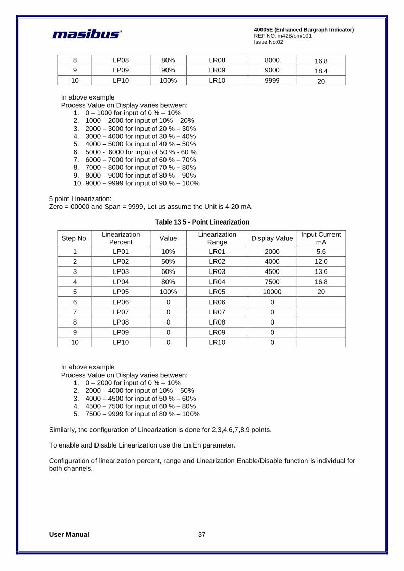
In above example Process Value on Display varies between:
1. 0 – 1000 for input of 0 % – 10% 2. 1000 – 2000 for input of 10% – 20% 3. 2000 – 3000 for input of 20 % – 30% 4. 3000 – 4000 for input of 30 % – 40% 5. 4000 – 5000 for input of 40 % – 50% 6. 5000 - 6000 for input of 50 % - 60 % 7. 6000 – 7000 for input of 60 % – 70% 8. 7000 – 8000 for input of 70 % – 80% 9. 8000 – 9000 for input of 80 % – 90% 10. 9000 – 9999 for input of 90 % – 100%
5 point Linearization: Zero = 00000 and Span = 9999, Let us assume the Unit is 4-20 mA.
Table 13 5 - Point Linearization
In above example Process Value on Display varies between:
1. 0 – 2000 for input of 0 % – 10% 2. 2000 – 4000 for input of 10% – 50% 3. 4000 – 4500 for input of 50 % – 60% 4. 4500 – 7500 for input of 60 % – 80% 5. 7500 – 9999 for input of 80 % – 100%
Similarly, the configuration of Linearization is done for 2,3,4,6,7,8,9 points. To enable and Disable Linearization use the Ln.En parameter. Configuration of linearization percent, range and Linearization Enable/Disable function is individual for both channels.
8 LP08 80% LR08 8000 16.8
9 LP09 90% LR09 9000 18.4
10 LP10 100% LR10 9999 20
Step No. Linearization
Percent Value
Linearization Range
Display Value Input Current
mA
1 LP01 10% LR01 2000 5.6
2 LP02 50% LR02 4000 12.0
3 LP03 60% LR03 4500 13.6
4 LP04 80% LR04 7500 16.8
5 LP05 100% LR05 10000 20
6 LP06 0 LR06 0
7 LP07 0 LR07 0
8 LP08 0 LR08 0
9 LP09 0 LR09 0
10 LP10 0 LR10 0
User Manual 38
40005E (Enhanced Bargraph Indicator) REF NO: m42B/om/101 Issue No: 02
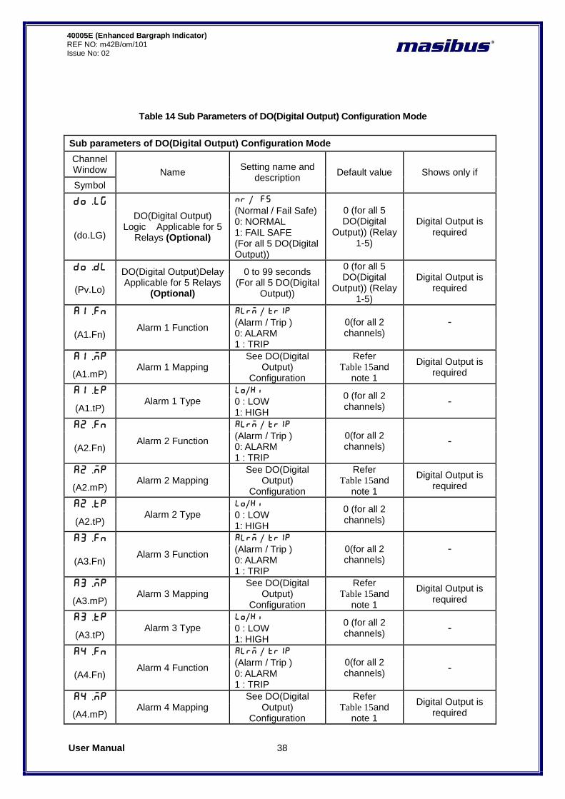
Table 14 Sub Parameters of DO(Digital Output) Configuration Mode
Sub parameters of DO(Digital Output) Configuration Mode
Channel Window Name
Setting name and description
Default value Shows only if
Symbol
do.lg DO(Digital Output)
Logic Applicable for 5 Relays (Optional)
nr / fs (Normal / Fail Safe) 0: NORMAL 1: FAIL SAFE (For all 5 DO(Digital Output))
0 (for all 5 DO(Digital
Output)) (Relay 1-5)
Digital Output is required (do.LG)
do.dl DO(Digital Output)Delay Applicable for 5 Relays
(Optional)
0 to 99 seconds (For all 5 DO(Digital
Output))
0 (for all 5 DO(Digital
Output)) (Relay 1-5)
Digital Output is required (Pv.Lo)
a1.fn
Alarm 1 Function
ALrm / TRIP (Alarm / Trip ) 0: ALARM 1 : TRIP
0(for all 2 channels)
-
(A1.Fn)
a1.mp Alarm 1 Mapping
See DO(Digital Output)
Configuration
Refer Table 15and
note 1
Digital Output is required (A1.mP)
a1.tp Alarm 1 Type
lo/Hi 0 : LOW 1: HIGH
0 (for all 2 channels)
- (A1.tP)
a2.fn
Alarm 2 Function
ALrm / TRIP (Alarm / Trip ) 0: ALARM 1 : TRIP
0(for all 2 channels)
- (A2.Fn)
a2.mp Alarm 2 Mapping
See DO(Digital Output)
Configuration
Refer Table 15and
note 1
Digital Output is required (A2.mP)
a2.tp Alarm 2 Type
lo/Hi 0 : LOW 1: HIGH
0 (for all 2 channels) (A2.tP)
A3.fn
Alarm 3 Function
ALrm / TRIP (Alarm / Trip ) 0: ALARM 1 : TRIP
0(for all 2 channels)
-
(A3.Fn)
A3.mp Alarm 3 Mapping
See DO(Digital Output)
Configuration
Refer Table 15and
note 1
Digital Output is required (A3.mP)
A3.tp Alarm 3 Type
lo/Hi 0 : LOW 1: HIGH
0 (for all 2 channels)
- (A3.tP)
A4.fn
Alarm 4 Function
ALrm / TRIP (Alarm / Trip ) 0: ALARM 1 : TRIP
0(for all 2 channels)
- (A4.Fn)
A4.mp Alarm 4 Mapping
See DO(Digital Output)
Configuration
Refer Table 15and
note 1
Digital Output is required (A4.mP)
User Manual 39
40005E (Enhanced Bargraph Indicator) REF NO: m42B/om/101 Issue No:02
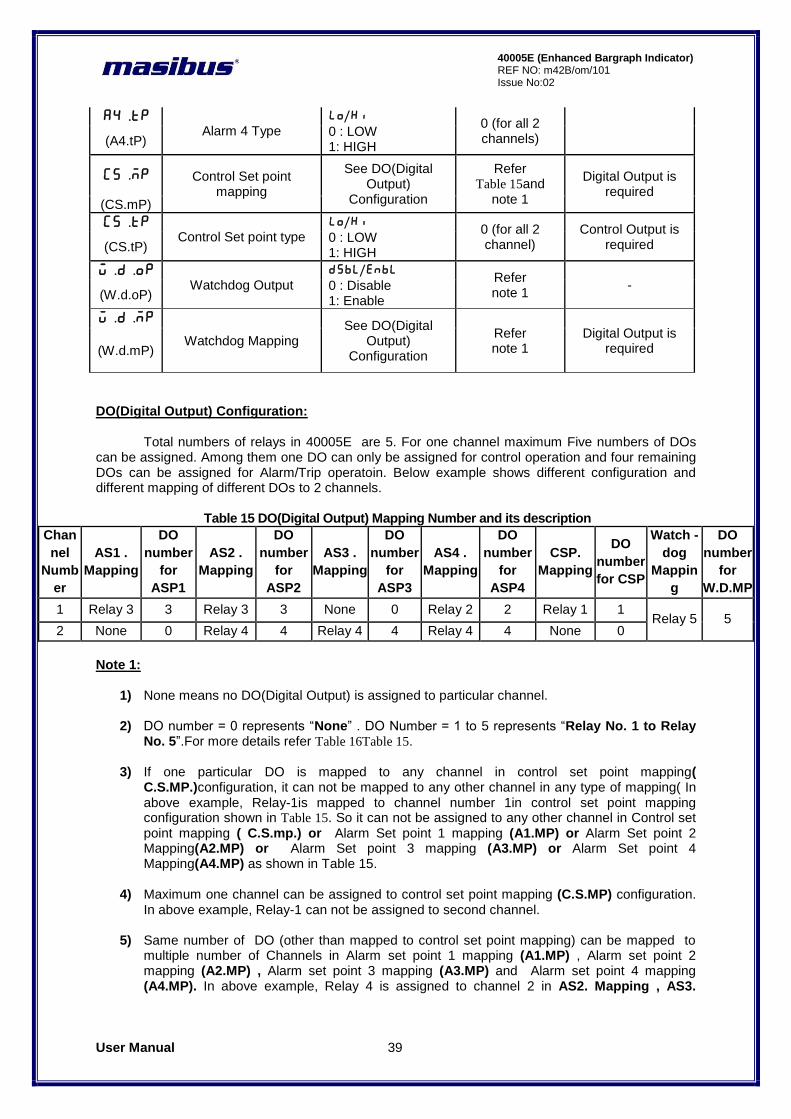
A4.tp
Alarm 4 Type lo/Hi 0 : LOW 1: HIGH
0 (for all 2 channels) (A4.tP)
CS.mp Control Set point mapping
See DO(Digital Output)
Configuration
Refer Table 15and
note 1
Digital Output is required
(CS.mP)
CS.tp Control Set point type
lo/Hi 0 : LOW 1: HIGH
0 (for all 2 channel)
Control Output is required (CS.tP)
W.D.op Watchdog Output
dsbl/enbl 0 : Disable 1: Enable
Refer note 1
- (W.d.oP)
W.D.mp
Watchdog Mapping See DO(Digital
Output) Configuration
Refer note 1
Digital Output is required (W.d.mP)
DO(Digital Output) Configuration:
Total numbers of relays in 40005E are 5. For one channel maximum Five numbers of DOs can be assigned. Among them one DO can only be assigned for control operation and four remaining DOs can be assigned for Alarm/Trip operatoin. Below example shows different configuration and different mapping of different DOs to 2 channels.
Table 15 DO(Digital Output) Mapping Number and its description
Chan
nel
Numb
er
AS1 .
Mapping
DO
number
for
ASP1
AS2 .
Mapping
DO
number
for
ASP2
AS3 .
Mapping
DO
number
for
ASP3
AS4 .
Mapping
DO
number
for
ASP4
CSP.
Mapping
DO
number
for CSP
Watch -
dog
Mappin
g
DO
number
for
W.D.MP
1 Relay 3 3 Relay 3 3 None 0 Relay 2 2 Relay 1 1 Relay 5 5
2 None 0 Relay 4 4 Relay 4 4 Relay 4 4 None 0
Note 1:
1) None means no DO(Digital Output) is assigned to particular channel. 2) DO number = 0 represents “None” . DO Number = 1 to 5 represents “Relay No. 1 to Relay
No. 5”.For more details refer Table 16Table 15.
3) If one particular DO is mapped to any channel in control set point mapping( C.S.MP.)configuration, it can not be mapped to any other channel in any type of mapping( In above example, Relay-1is mapped to channel number 1in control set point mapping configuration shown in Table 15. So it can not be assigned to any other channel in Control set point mapping ( C.S.mp.) or Alarm Set point 1 mapping (A1.MP) or Alarm Set point 2 Mapping(A2.MP) or Alarm Set point 3 mapping (A3.MP) or Alarm Set point 4 Mapping(A4.MP) as shown in Table 15.
4) Maximum one channel can be assigned to control set point mapping (C.S.MP) configuration. In above example, Relay-1 can not be assigned to second channel.
5) Same number of DO (other than mapped to control set point mapping) can be mapped to multiple number of Channels in Alarm set point 1 mapping (A1.MP) , Alarm set point 2 mapping (A2.MP) , Alarm set point 3 mapping (A3.MP) and Alarm set point 4 mapping (A4.MP). In above example, Relay 4 is assigned to channel 2 in AS2. Mapping , AS3.

User Manual 40
40005E (Enhanced Bargraph Indicator) REF NO: m42B/om/101 Issue No: 02
Mapping and AS4. Mapping, Relay 3 is mapped to channel 1 in AS1. Mapping and AS2. Mapping.
6) Based On Watchdog Output ( Disable / Enable) selection , Error messages will be shown. i.e.
if Watchdog Output is “disabled” , then no error message will be shown and other operation goes smoothly. When Watchdog Output is “enabled”, then based on faults, error messages will be displayed on CHANNEL window. For more detail on watchdog operation and error messages, please refer topic
User Manual 41
40005E (Enhanced Bargraph Indicator) REF NO: m42B/om/101 Issue No:02
8.4 Watchdog Timer(WDT) / Watchdog Output Operation.
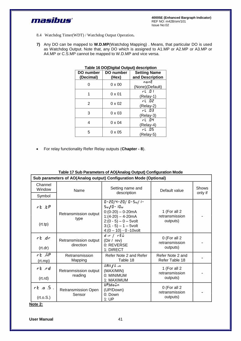
7) Any DO can be mapped to W.D.MP(Watchdog Mapping) . Means, that particular DO is used
as Watchdog Output. Note that, any DO which is assigned to A1.MP or A2.MP or A3.MP or A4.MP or C.S.MP cannot be mapped to W.D.MP and vice versa.
Table 16 DO(Digital Output) description
DO number (Decimal)
DO number (Hex)
Setting Name and Description
0 0 x 00 none
(None)(Default)
1 0 x 01 Rl.01
(Relay-1)
2 0 x 02 Rl.02
(Relay-2)
3 0 x 03 Rl.03
(Relay-3)
4 0 x 04 Rl.04
(Relay-4)
5 0 x 05 Rl.05
(Relay-5)
For relay functionality Refer Relay outputs (Chapter - 8).
Table 17 Sub Parameters of AO(Analog Output) Configuration Mode
Sub parameters of AO(Analog output) Configuration Mode (Optional)
Channel Window Name
Setting name and description
Default value Shows only if
Symbol
rt.tp
Retransmission output type
0-20/4-20/ 0-5v/1-
5v/0-10v 0:(0-20) – 0-20mA 1:(4-20) – 4-20mA 2:(0 - 5) – 0 – 5volt 3:(1 - 5) – 1 – 5volt 4:(0 – 10) - 0 -10volt
1 (For all 2 retransmission
outputs) -
(rt.tp)
rt.dr Retransmission output direction
Dir / rew (Dir / rev) 0: REVERSE 1: DIRECT
0 (For all 2 retransmission
outputs) -
(rt.dr)
rt.mp Retransmission Mapping
Refer Note 2 and Refer Table 18
Refer Note 2 and Refer Table 18
- (rt.mp)
rt.rd Retranmsission output reading
max/min (MAX/MIN) 0: MINIMUM 1: MAXIMUM
1 (For all 2 retransmission
outputs) -
(rt.rd)
rt.o.s. Retransmission Open Sensor
UP/Down (UP/Down) 0: Down 1: UP
0 (For all 2 retransmission
outputs) -
(rt.o.S.)
Note 2:
User Manual 42
40005E (Enhanced Bargraph Indicator) REF NO: m42B/om/101 Issue No: 02
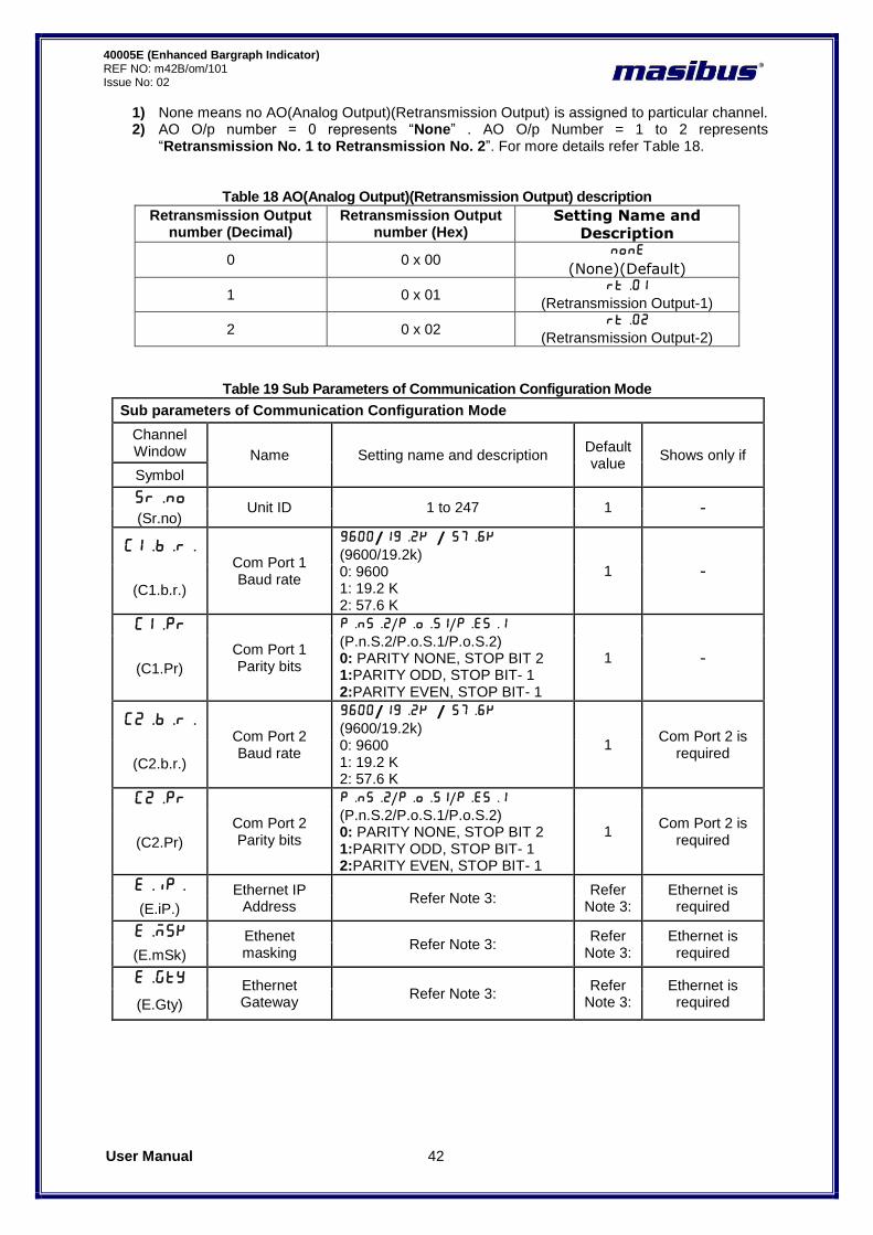
1) None means no AO(Analog Output)(Retransmission Output) is assigned to particular channel. 2) AO O/p number = 0 represents “None” . AO O/p Number = 1 to 2 represents
“Retransmission No. 1 to Retransmission No. 2”. For more details refer Table 18.
Table 18 AO(Analog Output)(Retransmission Output) description
Retransmission Output number (Decimal)
Retransmission Output number (Hex)
Setting Name and
Description
0 0 x 00 none
(None)(Default)
1 0 x 01 Rt.01
(Retransmission Output-1)
2 0 x 02 Rt.02
(Retransmission Output-2)
Table 19 Sub Parameters of Communication Configuration Mode
Sub parameters of Communication Configuration Mode
Channel Window Name Setting name and description
Default value
Shows only if
Symbol
sr.no Unit ID 1 to 247 1 -
(Sr.no)
C1.B.r. Com Port 1 Baud rate
9600/19.2k// 57.6k (9600/19.2k) 0: 9600 1: 19.2 K 2: 57.6 K
1 -
(C1.b.r.)
C1.pr
Com Port 1 Parity bits
P.nS.2/P.o.s1/P.ES.1 (P.n.S.2/P.o.S.1/P.o.S.2) 0: PARITY NONE, STOP BIT 2 1:PARITY ODD, STOP BIT- 1 2:PARITY EVEN, STOP BIT- 1
1 - (C1.Pr)
C2.B.r. Com Port 2 Baud rate
9600/19.2k// 57.6k (9600/19.2k) 0: 9600 1: 19.2 K 2: 57.6 K
1 Com Port 2 is
required (C2.b.r.)
C2.pr
Com Port 2 Parity bits
P.nS.2/P.o.s1/P.ES.1 (P.n.S.2/P.o.S.1/P.o.S.2) 0: PARITY NONE, STOP BIT 2 1:PARITY ODD, STOP BIT- 1 2:PARITY EVEN, STOP BIT- 1
1 Com Port 2 is
required (C2.Pr)
E.iP. Ethernet IP Address
Refer Note 3: Refer
Note 3: Ethernet is required (E.iP.)
e.msk Ethenet masking
Refer Note 3: Refer
Note 3: Ethernet is required (E.mSk)
e.gty Ethernet Gateway
Refer Note 3: Refer
Note 3: Ethernet is required (E.Gty)
User Manual 43
40005E (Enhanced Bargraph Indicator) REF NO: m42B/om/101 Issue No:02
Note 3:
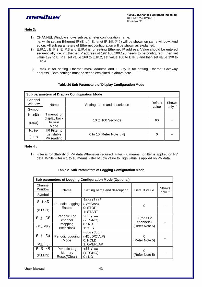
1) CHANNEL Window shows sub parameter configuration name.
i.e. while setting Ethernet IP (E.Ip.), Ethenet IP 1(E.ip.1) will be shown on same window. And so on. All sub parameters of Ethernet configuration will be shown as explained.
2) E.IP.1 , E.IP.2, E.IP.3 and E.IP.4 is for setting Ethernet IP address. Value should be entered sequencially. i.e. if Ethernet IP address of 192.168.100.190 needs to be configured , then set value 192 to E.IP.1, set value 168 to E.IP.2, set value 100 to E.IP.3 and then set value 190 to E.IP.4.
3) E.msk is for setting Ethernet mask address and E. Gty is for setting Ethernet Gateway
address . Both settings must be set as explained in above note.
Table 20 Sub Parameters of Display Configuration Mode
Sub parameters of Display Configuration Mode
Channel Window Name Setting name and description
Default value
Shows only if
Symbol
t.out Timeout for display back
to Run Mode
10 to 100 Seconds 60 - (t.oUt)
Fltr IIR Filter to get stable
PV reading 0 to 10 (Refer Note : 4) 0 -
(FLtr)
Note 4 :
1) Filter is for Stability of PV data Whenever required. Filter = 0 means no filter is applied on PV data. While Filter = 1 to 10 means Filter of Low value to High value is applied on PV data.
Table 21Sub Parameters of Logging Configuration Mode
Sub parameters of Logging Configuration Mode (Optional)
Channel Window Name Setting name and description Default value
Shows only if
Symbol
p.log Periodic Logging Enable
strt/stop (Strt/Stop) 0: STOP 1: START
0 -
(P.LOG)
p.l.mp Periodic Log
channel mapping
(selection)
yes / no (YES/NO) 0 : NO 1: YES
0 (for all 2 channels)
(Refer Note 5) -
(P.L.MP)
p.l.md Periodic Logging Mode
hold/OWLP (HOLD/OVLP) 0: HOLD 1: OVERLAP
0 (Refer Note 5)
-
(P.L.md)
P.M.RS Periodic Log Memory
Reset(/Clear)
yes / no (YES/NO) 0 : NO
0 (Refer Note 5)
- (P.M.rS)
User Manual 44
40005E (Enhanced Bargraph Indicator) REF NO: m42B/om/101 Issue No: 02
1: YES
p.l.HH Periodic Log time - Hour
0 to 23 0
(Refer Note 5) -
(P.L.HH)
p.l.mm Periodic Log time – Minute
0 to 59 0
(Refer Note 5) -
(P.L.MM)
p.l.ss Periodic Log time – Second
0 to 59 1
(Refer Note 5) -
(P.L.SS)
E.log Event Logging
Enable
strt/stop (Strt/Stop) 0: STOP 1: START
0 - (E.LOG)
E.l.mp Event Log channel mapping
(selection)
yes / no (YES/NO) 0 : NO 1: YES
0 (for all 2 channels)
(Refer Note 5) -
(E.L.MP)
E.l.md Event Logging
Mode
hold/OWLP (HOLD/OVLP) 0: HOLD 1: OVERLAP
0 - (E.L.Md)
E.M.RS Event Log Memory
Reset(/Clear)
yes / no (YES/NO) 0 : NO 1: YES
0 - (E.M.rS)
Hour RTC – Hour 0 to 23 0 -
(Hour)
Min RTC – Minute 0 to 59 0 -
(Min)
Sec RTC – Second 0 to 59 0 -
(Sec)
Date RTC – Date 1 to 31 0 -
(date)
Mon RTC – Month 1 to 12 0 -
(Mon)
year RTC – Year 1 to 255 0 -
(yEAr)
Note 5:
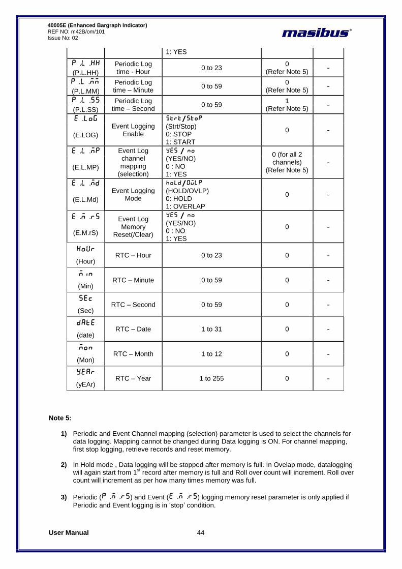
1) Periodic and Event Channel mapping (selection) parameter is used to select the channels for data logging. Mapping cannot be changed during Data logging is ON. For channel mapping, first stop logging, retrieve records and reset memory.
2) In Hold mode , Data logging will be stopped after memory is full. In Ovelap mode, datalogging will again start from 1
st record after memory is full and Roll over count will increment. Roll over
count will increment as per how many times memory was full.
3) Periodic (P.M.RS) and Event (E.M.RS) logging memory reset parameter is only applied if
Periodic and Event logging is in „stop‟ condition.
User Manual 45
40005E (Enhanced Bargraph Indicator) REF NO: m42B/om/101 Issue No:02
4) Periodic Log time is settable in HH:MM:SS format. By default it is 00:00:01.
5) RTC related parameters are for setting date and time in Data logging.
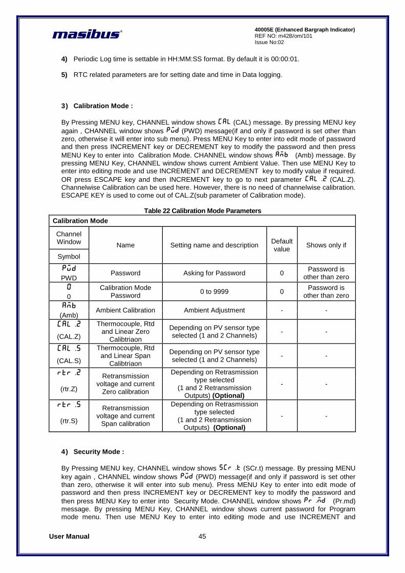
3) Calibration Mode :
By Pressing MENU key, CHANNEL window shows Cal (CAL) message. By pressing MENU key
again , CHANNEL window shows pWd (PWD) message(if and only if password is set other than zero, otherwise it will enter into sub menu). Press MENU Key to enter into edit mode of password and then press INCREMENT key or DECREMENT key to modify the password and then press
MENU Key to enter into Calibration Mode. CHANNEL window shows Amb (Amb) message. By pressing MENU Key, CHANNEL window shows current Ambient Value. Then use MENU Key to enter into editing mode and use INCREMENT and DECREMENT key to modify value if required.
OR press ESCAPE key and then INCREMENT key to go to next parameter Cal.z (CAL.Z). Channelwise Calibration can be used here. However, there is no need of channelwise calibration. ESCAPE KEY is used to come out of CAL.Z(sub parameter of Calibration mode).
Table 22 Calibration Mode Parameters
Calibration Mode
Channel Window
Name Setting name and description Default value
Shows only if
Symbol
PWD Password Asking for Password 0
Password is other than zero PWD
0 Calibration Mode Password
0 to 9999 0 Password is
other than zero 0
Amb Ambient Calibration Ambient Adjustment - -
(Amb)
Cal.z Thermocouple, Rtd and Linear Zero
Calibtriaon
Depending on PV sensor type selected (1 and 2 Channels)
- - (CAL.Z)
Cal.s Thermocouple, Rtd and Linear Span
Calibtriaon
Depending on PV sensor type selected (1 and 2 Channels)
- - (CAL.S)
rtr.z Retransmission voltage and current
Zero calibration
Depending on Retrasmission type selected
(1 and 2 Retransmission Outputs) (Optional)
- - (rtr.Z)
rtr.s Retransmission voltage and current
Span calibration
Depending on Retrasmission type selected
(1 and 2 Retransmission Outputs) (Optional)
- - (rtr.S)
4) Security Mode :
By Pressing MENU key, CHANNEL window shows sCr.t (SCr.t) message. By pressing MENU
key again , CHANNEL window shows pWd (PWD) message(if and only if password is set other than zero, otherwise it will enter into sub menu). Press MENU Key to enter into edit mode of password and then press INCREMENT key or DECREMENT key to modify the password and
then press MENU Key to enter into Security Mode. CHANNEL window shows Pr.md (Pr.md) message. By pressing MENU Key, CHANNEL window shows current password for Program mode menu. Then use MENU Key to enter into editing mode and use INCREMENT and
User Manual 46
40005E (Enhanced Bargraph Indicator) REF NO: m42B/om/101 Issue No: 02
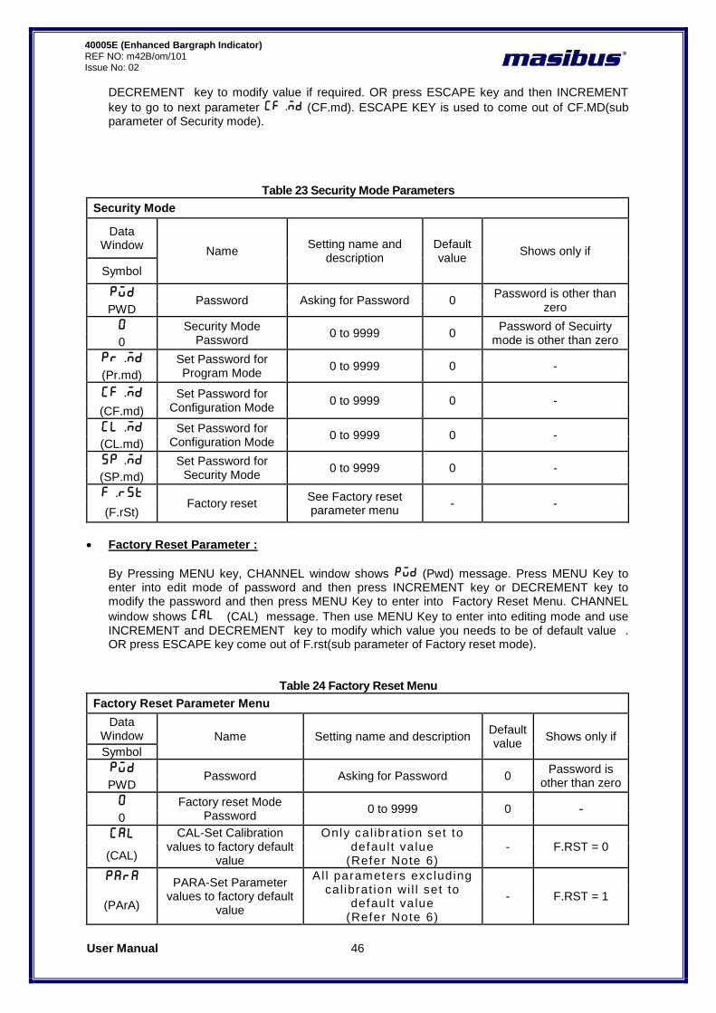
DECREMENT key to modify value if required. OR press ESCAPE key and then INCREMENT
key to go to next parameter Cf.md (CF.md). ESCAPE KEY is used to come out of CF.MD(sub parameter of Security mode).
Table 23 Security Mode Parameters
Security Mode
Data Window
Name Setting name and
description Default value
Shows only if
Symbol
PWD Password Asking for Password 0
Password is other than zero PWD
0 Security Mode Password
0 to 9999 0 Password of Secuirty
mode is other than zero 0
pr.md Set Password for Program Mode
0 to 9999 0 - (Pr.md)
CF.md Set Password for Configuration Mode
0 to 9999 0 - (CF.md)
Cl.md Set Password for Configuration Mode
0 to 9999 0 - (CL.md)
sp.md Set Password for Security Mode
0 to 9999 0 - (SP.md)
f.rst Factory reset
See Factory reset parameter menu
- - (F.rSt)
Factory Reset Parameter :
By Pressing MENU key, CHANNEL window shows pwd (Pwd) message. Press MENU Key to enter into edit mode of password and then press INCREMENT key or DECREMENT key to modify the password and then press MENU Key to enter into Factory Reset Menu. CHANNEL
window shows CAL (CAL) message. Then use MENU Key to enter into editing mode and use INCREMENT and DECREMENT key to modify which value you needs to be of default value . OR press ESCAPE key come out of F.rst(sub parameter of Factory reset mode).
Table 24 Factory Reset Menu
Factory Reset Parameter Menu
Data Window Name Setting name and description
Default value
Shows only if
Symbol
PWD Password Asking for Password 0
Password is other than zero PWD
0 Factory reset Mode Password
0 to 9999 0 - 0
CAL CAL-Set Calibration values to factory default
value
Only cal ibrat ion set to defaul t va lue
(Refer Note 6) - F.RST = 0
(CAL)
para PARA-Set Parameter values to factory default
value
Al l parameters exc luding cal ibrat ion wi l l set to
defaul t va lue (Refer Note 6)
- F.RST = 1 (PArA)

User Manual 47
40005E (Enhanced Bargraph Indicator) REF NO: m42B/om/101 Issue No:02
All ALL-Set ALL values to
factory default value
Calibration and parameters will set to default value
(Refer Note 6) - F.RST = 2
(ALL)
Note 6:
1) After resetting Calibration / Parameters / All values to factory reset values, the CHANNEL
window will display wait (Wait) message for few seconds and then display will reset
automatically with default factory values.
User Manual 48
40005E (Enhanced Bargraph Indicator) REF NO: m42B/om/101 Issue No: 02
8. ALARM OUTPUT, CONTROL OUTPUT , DIGITAL OUTPUT AND WATCHDOG OUTPUT OPERATION
8.1 Alarm Output Operation
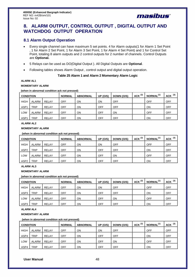
Every single channel can have maximum 5 set points. 4 for Alarm outputs(1 for Alarm 1 Set Point , 1 for Alarm 2 Set Point, 1 for Alarm 3 Set Point, 1 for Alarm 4 Set Point) and 1 for Control Set Point, totaling 8 alarm outputs and 2 control outputs for 2 number of channels. Control Outputs are Optional.
5 Relays can be used as DO(Digital Output ). All Digital Outputs are Optional.
Following tables shows Alarm Output , control output and digital output operation.
Table 25 Alarm 1 and Alarm 2 Momentary Alarm Logic
ALARM AL1
MOMEMTARY ALARM
(when in abnormal condition ack not pressed)
CONDITION NORMAL ABNORMAL UP (O/S) DOWN (O/S) ACK (2)
NORMAL(1)
ACK (3)
HIGH ALARM RELAY OFF ON ON OFF OFF OFF
ASP1 TRIP RELAY OFF ON OFF OFF ON OFF
LOW ALARM RELAY OFF ON OFF ON OFF OFF
ASP1 TRIP RELAY OFF ON OFF OFF ON OFF
ALARM AL2
MOMEMTARY ALARM
(when in abnormal condition ack not pressed)
CONDITION NORMAL ABNORMAL UP (O/S) DOWN (O/S) ACK (2)
NORMAL(1)
ACK (3)
HIGH ALARM RELAY OFF ON ON OFF OFF OFF
ASP2 TRIP RELAY OFF ON OFF OFF ON OFF
LOW ALARM RELAY OFF ON OFF ON OFF OFF
ASP2 TRIP RELAY OFF ON OFF OFF ON OFF
ALARM AL3
MOMEMTARY ALARM
(when in abnormal condition ack not pressed)
CONDITION NORMAL ABNORMAL UP (O/S) DOWN (O/S) ACK (2)
NORMAL(1)
ACK (3)
HIGH ALARM RELAY OFF ON ON OFF OFF OFF
ASP3 TRIP RELAY OFF ON OFF OFF ON OFF
LOW ALARM RELAY OFF ON OFF ON OFF OFF
ASP3 TRIP RELAY OFF ON OFF OFF ON OFF
ALARM AL4
MOMEMTARY ALARM
(when in abnormal condition ack not pressed)
CONDITION NORMAL ABNORMAL UP (O/S) DOWN (O/S) ACK (2)
NORMAL(1)
ACK (3)
HIGH ALARM RELAY OFF ON ON OFF OFF OFF
ASP4 TRIP RELAY OFF ON OFF OFF ON OFF
LOW ALARM RELAY OFF ON OFF ON OFF OFF
ASP4 TRIP RELAY OFF ON OFF OFF ON OFF
User Manual 49
40005E (Enhanced Bargraph Indicator) REF NO: m42B/om/101 Issue No:02
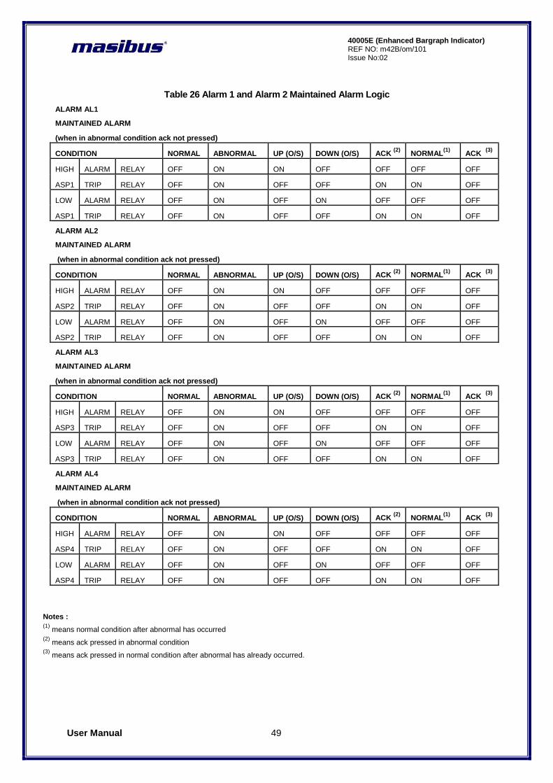
Table 26 Alarm 1 and Alarm 2 Maintained Alarm Logic
ALARM AL1
MAINTAINED ALARM
(when in abnormal condition ack not pressed)
CONDITION NORMAL ABNORMAL UP (O/S) DOWN (O/S) ACK (2)
NORMAL(1)
ACK (3)
HIGH ALARM RELAY OFF ON ON OFF OFF OFF OFF
ASP1 TRIP RELAY OFF ON OFF OFF ON ON OFF
LOW ALARM RELAY OFF ON OFF ON OFF OFF OFF
ASP1 TRIP RELAY OFF ON OFF OFF ON ON OFF
ALARM AL2
MAINTAINED ALARM
(when in abnormal condition ack not pressed)
CONDITION NORMAL ABNORMAL UP (O/S) DOWN (O/S) ACK (2)
NORMAL(1)
ACK (3)
HIGH ALARM RELAY OFF ON ON OFF OFF OFF OFF
ASP2 TRIP RELAY OFF ON OFF OFF ON ON OFF
LOW ALARM RELAY OFF ON OFF ON OFF OFF OFF
ASP2 TRIP RELAY OFF ON OFF OFF ON ON OFF
ALARM AL3
MAINTAINED ALARM
(when in abnormal condition ack not pressed)
CONDITION NORMAL ABNORMAL UP (O/S) DOWN (O/S) ACK (2)
NORMAL(1)
ACK (3)
HIGH ALARM RELAY OFF ON ON OFF OFF OFF OFF
ASP3 TRIP RELAY OFF ON OFF OFF ON ON OFF
LOW ALARM RELAY OFF ON OFF ON OFF OFF OFF
ASP3 TRIP RELAY OFF ON OFF OFF ON ON OFF
ALARM AL4
MAINTAINED ALARM
(when in abnormal condition ack not pressed)
CONDITION NORMAL ABNORMAL UP (O/S) DOWN (O/S) ACK (2)
NORMAL(1)
ACK (3)
HIGH ALARM RELAY OFF ON ON OFF OFF OFF OFF
ASP4 TRIP RELAY OFF ON OFF OFF ON ON OFF
LOW ALARM RELAY OFF ON OFF ON OFF OFF OFF
ASP4 TRIP RELAY OFF ON OFF OFF ON ON OFF
Notes : (1)
means normal condition after abnormal has occurred (2)
means ack pressed in abnormal condition (3)
means ack pressed in normal condition after abnormal has already occurred.
User Manual 50
40005E (Enhanced Bargraph Indicator) REF NO: m42B/om/101 Issue No: 02
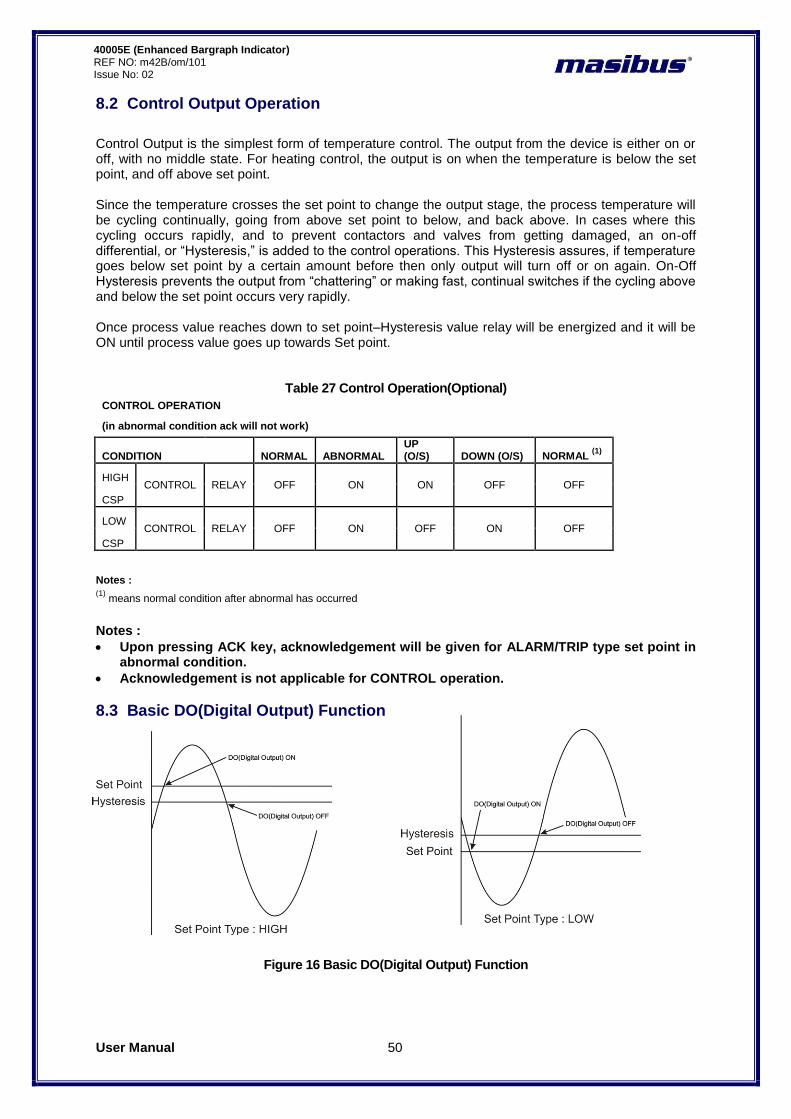
8.2 Control Output Operation
Control Output is the simplest form of temperature control. The output from the device is either on or off, with no middle state. For heating control, the output is on when the temperature is below the set point, and off above set point. Since the temperature crosses the set point to change the output stage, the process temperature will be cycling continually, going from above set point to below, and back above. In cases where this cycling occurs rapidly, and to prevent contactors and valves from getting damaged, an on-off differential, or “Hysteresis,” is added to the control operations. This Hysteresis assures, if temperature goes below set point by a certain amount before then only output will turn off or on again. On-Off Hysteresis prevents the output from “chattering” or making fast, continual switches if the cycling above and below the set point occurs very rapidly. Once process value reaches down to set point–Hysteresis value relay will be energized and it will be ON until process value goes up towards Set point.
Table 27 Control Operation(Optional)
CONTROL OPERATION
(in abnormal condition ack will not work)
CONDITION NORMAL ABNORMAL UP (O/S) DOWN (O/S) NORMAL
(1)
HIGH CONTROL RELAY OFF ON ON OFF OFF
CSP
LOW CONTROL RELAY OFF ON OFF ON OFF
CSP
Notes :
Upon pressing ACK key, acknowledgement will be given for ALARM/TRIP type set point in abnormal condition.
Acknowledgement is not applicable for CONTROL operation.
8.3 Basic DO(Digital Output) Function
Figure 16 Basic DO(Digital Output) Function
Notes : (1)
means normal condition after abnormal has occurred

User Manual 51
40005E (Enhanced Bargraph Indicator) REF NO: m42B/om/101 Issue No:02
8.4 Watchdog Timer(WDT) / Watchdog Output Operation
The WDT, when enabled, operates from the internal Low-Power RC (LPRC) Oscillator clock source. The WDT can be used to detect system software malfunctions by resetting the device if the WDT is not cleared periodically in software. If malfunctioning of device persist even after watchdog reset device will go into shutdown mode followed by error messages on display as per Table 28. Device Fault can be monitored by a failsafe relay output which is mapped for watchdog output. When WDT is disable device will continue to work with fault. The Fault LED will be on in this condition.
Table 28 Error Messages and its Description
Error Messages Fault
Error 1 CPU card EEPROM failure
Error 2 SC 1 card ADC failure
Error 3 SC 1 card EEPROM failure
Error 4 SC 2 card ADC failure
Error 5 SC 2 card EEPROM failure
Error 6 SC 3 card ADC failure
Error 7 SC 3 card EEPROM failure
Error 8 CPU card Controller Hang – failure
Error 9 Communication between CPU and Display card Failure
Watchdog Relay : This relay is normally in ON condition and it will be OFF when any problem occurs with Device.

User Manual 52
40005E (Enhanced Bargraph Indicator) REF NO: m42B/om/101 Issue No: 02
9. CALIBRATION PROCEDURE
Calibration is provided for ambient temperature, PV sensor input, Analog Output (Retransmission output)(Optional). First select the calibration function as described below and then follow the procedure depending on the parameter to be calibrated. The sequences of parameters that will be available for calibration are listed below:
Ambient temperature adjustment
PV Sensor input
Retransmission output (calibration for voltage or current) Ambient temperature adjustment:- CHANNEL window shows Amb (Ambient temperature adjusts).Press MENU key to show the current Ambient value. CHANNEL window shows ambient temperature measured by the ENHANCED BARGRAPH INDICATOR and by applying old calibration data. Press MENU key again to edit the displayed value.DP of last digit and last digit itself will blink to indicate that the value can be changed. Use INC / DEC (Here Decrement key is used to shift the digit in editing mode) key to adjust it to desired value. Once the desired value is set then press MENU key, the blinking DP will go off to indicate that the value has been registered. The ENHANCED BARGRAPH INDICATOR will automatically save all the new calculations. Ambient temperature adjustment is over. Press ESC key and then press INC key to calibrate other parameters or press Escape key to come out to normal operation. PV input sensor calibration:- Note that all signal cards and all input type group must be calibrated before proceeding further. There is no need to calibrate all input types. Just calibrate only one input type from one group and all other input types from the same group will be calibrated automatically. Group calibration detail is given in following table.
Table 29 Group Calibration Detail
Group NO Input type Calibration for input
1 E,J,K,T,N,0-100mv Either of any input
2 B,R,S,-10 to 20mv Either of any input
3 Pt-100(RTD), CU53, NI120 Either of any input
4 0-5v,1-5V, 0-10V, 4-20mamp,0-20mamp
Either of any input
Note : Kindly Calibrate following input type for gaining better accuracy.
1) For Group Number 1, calibrate 0-100 mV input type. 2) For Group Number 2, calibrate -10 to 20 mV input type. 3) For Group Number 3, calibrate Pt-100(RTD) input type and 4) For Group Number 4, calibrate 0 to 10 V input type.
When user enters in calibration zero menu, CHANNEL window shows CAL.z (CAL.Z) message. Pressing MENU key again CHANNEL window shows CH-1 (CH-1) message. Press MENU key, it shows the PV value of corresponding input for channel number 1. User can use any channel out of maximum number of channels(2) to calibrate input type for lower reading. Feed sensor input using a calibrator, such that process value is close to lower range value. Note: The ENHANCED BARGRAPH INDICATOR allows the user to calibrate sensor‟s input anywhere in the range, but it is recommended that it should calibrate the input at points close to lower and upper range values.

User Manual 53
40005E (Enhanced Bargraph Indicator) REF NO: m42B/om/101 Issue No:02
By pressing MENU key, DP of last digit and last digit itself will blink to indicate that the value can be changed. Use INC / DEC (Here Decrement key is used for shifting a digit) key to correct the displayed reading to the desired process value and press MENU key. When the calculations are over, the new calibration values are stored automatically and DATA window will show the calibrated value. When user enters in calibration zero menu, CHANNEL window shows CAL.z (CAL.Z) message. Pressing MENU key again CHANNEL window shows CH-1 (CH-1) message. Press MENU key, it shows the PV value of corresponding input for channel number 1. User can use any channel out of maximum number of channels(2) to calibrate input type for span reading. PV display shows process value corresponding to input sensor value with old calibration data. Feed sensor input using a calibrator, such that process value is close to sensor‟s upper range value. Press MENU key to edit the value. Use INC / DEC (Here Decrement key is used for shifting a digit in editing mode) key to arrive at the desired process value. Press MENU key to register the changes. When the calculations are over, the new calibration values are stored automatically and CHANNEL window will show the calibrated value. Zero and Span calibration is over In case, the ENHANCED BARGRAPH INDICATOR cannot complete the calibration due to any reason, it will hold previous calibration parameters. Calibration for input sensor is over. Retransmission output calibration (Voltage/current output)(Optional):- In Calibration mode, press INC key repeatedly, till CHANNEL window shows message rtr.Z (retransmission output zero calibration). By pressing MENU key, CHANNEL windows shows rtr.1 (rtr.1) . It indicates which Retransmission output needs to be calibrated. By pressing MENU key, CHANNEL window shows the value being outputted on Retransmission output terminals. In 40005E there are 2 number of Analog Output(Retransmission Output) are available. Now, measure the value using a highly accurate digital multi meter. Press MENU key to enter into editing mode. Use INC / DEC (Here Decrement key is used for shifting a digit in editing mode) key to correct the displayed reading to the measured value. The ENHANCED BARGRAPH INDICATOR will store zero calibration value. Press the ESC key and then INC key to calibrate value for other Retransmission Output. Now press ESC to come out of Retransmission Zero calibration and press INC key to calibrate retransmission output span calibration menu. CHANNEL window shows the message rtr.S (retransmission output span calibration) ) By pressing MENU key, CHANNEL windows shows rtr.1 (rtr.1) . It indicates which Retransmission output needs to be calibrated. By pressing MENU key, CHANNEL window shows the value being outputted on Retransmission output terminals. In 40005E there are 2 number of Analog Output(Retransmission Output) are available. Now, measure the value using a highly accurate digital multi meter. Press MENU key to enter into editing mode. Use INC / DEC (Here Decrement key is used for shifting a digit in editing mode) key to correct the displayed reading to the measured value. The ENHANCED BARGRAPH INDICATOR will store zero calibration value. Press the ESC key and then INC key to calibrate value for other Retransmission Output. Now press ESC to come out of Retransmission Span calibration. Calibration for Retransmission output is over. Press MENU key to calibrate other parameters or press Escape key to come out to normal operation. Note: Disable Linearization of Linear input type before doing calibration of linear input type.
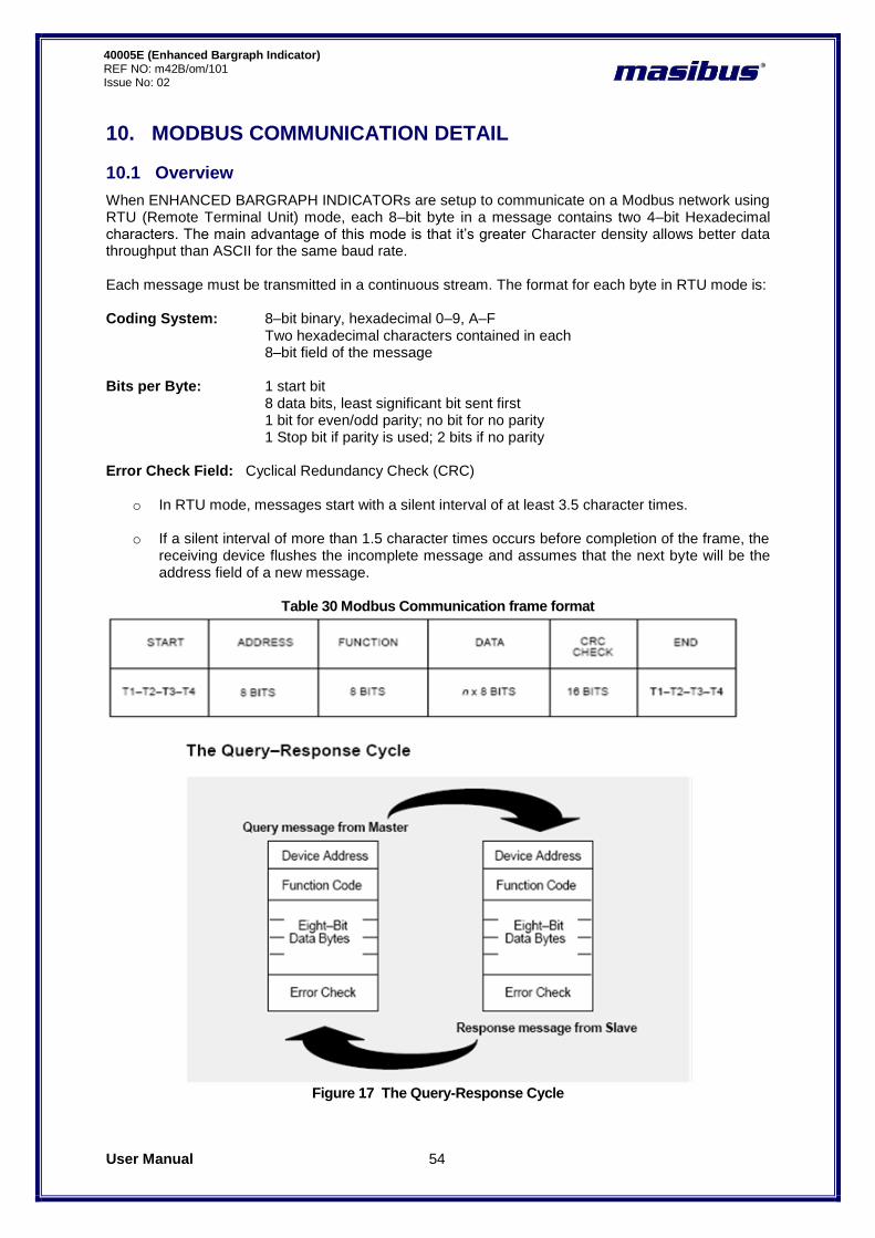
User Manual 54
40005E (Enhanced Bargraph Indicator) REF NO: m42B/om/101 Issue No: 02
10. MODBUS COMMUNICATION DETAIL
10.1 Overview
When ENHANCED BARGRAPH INDICATORs are setup to communicate on a Modbus network using RTU (Remote Terminal Unit) mode, each 8–bit byte in a message contains two 4–bit Hexadecimal characters. The main advantage of this mode is that it‟s greater Character density allows better data throughput than ASCII for the same baud rate. Each message must be transmitted in a continuous stream. The format for each byte in RTU mode is: Coding System: 8–bit binary, hexadecimal 0–9, A–F
Two hexadecimal characters contained in each 8–bit field of the message
Bits per Byte: 1 start bit 8 data bits, least significant bit sent first 1 bit for even/odd parity; no bit for no parity 1 Stop bit if parity is used; 2 bits if no parity
Error Check Field: Cyclical Redundancy Check (CRC)
o In RTU mode, messages start with a silent interval of at least 3.5 character times.
o If a silent interval of more than 1.5 character times occurs before completion of the frame, the receiving device flushes the incomplete message and assumes that the next byte will be the address field of a new message.
Table 30 Modbus Communication frame format
Figure 17 The Query-Response Cycle

User Manual 55
40005E (Enhanced Bargraph Indicator) REF NO: m42B/om/101 Issue No:02
o Valid slave device addresses are in the range of 0 – 247 decimal. o The individual slave devices are assigned addresses in the range of 1 – 247. o Address 0 is used for the broadcast address, which all slave devices recognize. o The data field is constructed using sets of two hexadecimal digits, in the range of 00 to FF
hexadecimal. o In RTU mode, messages include an error–checking field that is based on a
Cyclical Redundancy Check (CRC) method o The CRC field is two bytes, containing a 16–bit binary value. The CRC value is
Calculated by the transmitting device, which appends the CRC to the message
Use only following function codes for data read/write purpose
Table 31 Modbus Function code description
Function Code Description
01 NA
02 NA
03 Read Holding Registers
04 Read Input Registers
05 NA
06 Force Single Register
15 NA
16 Force Multiple Registers
10.2 Exception Responses
Except for broadcast messages, when a master device sends a query to a slave
Device it expects a normal response. One of four possible events can occur from The master‟s query: If the slave device receives the query without a communication error, and can handle the
query normally, it returns a normal response. If the slave does not receive the query due to a communication error, no Response is
returned. The master program will eventually process a timeout Condition for the query. If the slave receives the query, but detects a communication error (parity, LRC, or CRC), no
response is returned. The master program will eventually process a timeout condition for the query.
If the slave receives the query without a communication error, but cannot Handle it (for example, if the request is to read a non–existent coil or register), The slave will return an exception response informing the master of the nature of the error.
The exception response message has two fields that differentiate it from a normal Response: Query:
Table 32 Modbus Query frame format
Byte Contents Example
1 Slave Address 0A
2 Function 01
3 Starting Address Hi 04
4 Starting Address Lo A1
5 No Of Coils Hi 01
6 No Of Coils Lo 01
7 CRC Hi XX
8 CRC Lo XX
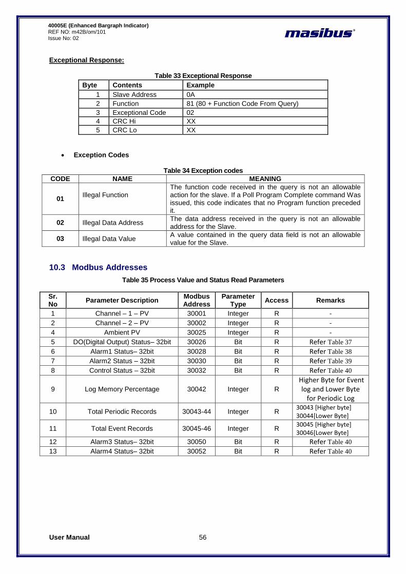
User Manual 56
40005E (Enhanced Bargraph Indicator) REF NO: m42B/om/101 Issue No: 02
Exceptional Response:
Table 33 Exceptional Response
Byte Contents Example
1 Slave Address 0A
2 Function 81 (80 + Function Code From Query)
3 Exceptional Code 02
4 CRC Hi XX
5 CRC Lo XX
Exception Codes
Table 34 Exception codes
CODE NAME MEANING
01 Illegal Function
The function code received in the query is not an allowable action for the slave. If a Poll Program Complete command Was issued, this code indicates that no Program function preceded it.
02 Illegal Data Address The data address received in the query is not an allowable address for the Slave.
03 Illegal Data Value A value contained in the query data field is not an allowable value for the Slave.
10.3 Modbus Addresses
Table 35 Process Value and Status Read Parameters
Sr. No
Parameter Description Modbus Address
Parameter Type
Access Remarks
1 Channel – 1 – PV 30001 Integer R - 2 Channel – 2 – PV 30002 Integer R - 4 Ambient PV 30025 Integer R -
5 DO(Digital Output) Status– 32bit 30026 Bit R Refer Table 37 6 Alarm1 Status– 32bit 30028 Bit R Refer Table 38 7 Alarm2 Status – 32bit 30030 Bit R Refer Table 39
8 Control Status – 32bit 30032 Bit R Refer Table 40
9 Log Memory Percentage 30042 Integer R
Higher Byte for Event log and Lower Byte
for Periodic Log
10 Total Periodic Records 30043-44 Integer R 30043 [Higher byte] 30044[Lower Byte]
11 Total Event Records 30045-46 Integer R 30045 [Higher byte] 30046[Lower Byte]
12 Alarm3 Status– 32bit 30050 Bit R Refer Table 40 13 Alarm4 Status– 32bit 30052 Bit R Refer Table 40

User Manual 57
40005E (Enhanced Bargraph Indicator) REF NO: m42B/om/101 Issue No:02
Table 36 Details of abnormal Conditions of Process Value
Abnormal Value (Integer) Description
32762 Reserved
32764 Channel Skip
32765 UNDER Value
32766 OVER Value
32767 Channel OPEN Indication
Table 37 DO (Digital Output) Status Register and its bits arrangement
Parameter DO(Digital Output) Status
DO(Digital Output) Status
Modbus Address
30026 30027
Bit No. 15 14 13 12 11 10 9 8
7 6 5 4 3 2 1 0 15 14 13 12 11 10 9 8
7 6 5 4 3 2 1 0
Description - - - - - - - - - - - - - - - - - - - - - - - - - - - - -
Rela
y-5
Rela
y-4
Rela
y-3
Rela
y-2
Rela
y-1
Table 38 Alarm 1 Status Register and its bits arrangement
Parameter Alarm 1 Status
Alarm 1 Status
Modbus Address
30028 30029
Bit No. 15 14 13 12 11 10 9 8
7 6 5 4 3 2 1 0 15 14 13 12 11 10 9 8
7 6 5 4 3 2 1 0
Description - - - - - - - - - - - - - - - - - - - - - - - - - - - - - - - -
Channel – 2
Channel – 1
Table 39 Alarm 2 Status Register and its bits arrangement
Parameter Alarm 2 Status
Alarm 2 Status
Modbus Address
30030 30031
Bit No. 15 14 13 12 11 10 9 8
7 6 5 4 3 2 1 0 15 14 13 12 11 10 9 8
7 6 5 4 3 2 1 0
Description - - - - - - - - - - - - - - - - - - - - - - - - - - - - - - - -
Channel – 2
Channel – 1
Above mentioned bit arrangement is applicable to other parameters as explained below.
Table 40 Other Status Registers
Parameter Control Status
Control Status
Modbus Address
30032 30033
Parameter Alarm 3 Status Alarm 3 Status
Modbus Address
30050 30051
Parameter Alarm 4 Status
Alarm 4 Status
Modbus Address
30052 30053
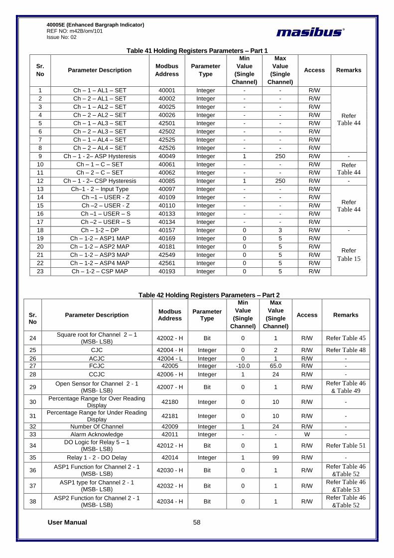
User Manual 58
40005E (Enhanced Bargraph Indicator) REF NO: m42B/om/101 Issue No: 02
Table 41 Holding Registers Parameters – Part 1
Sr.
No Parameter Description
Modbus
Address
Parameter
Type
Min
Value
(Single
Channel)
Max
Value
(Single
Channel)
Access Remarks
1 Ch – 1 – AL1 – SET 40001 Integer - - R/W
Refer
Table 44
2 Ch – 2 – AL1 – SET 40002 Integer - - R/W
3 Ch – 1 – AL2 – SET 40025 Integer - - R/W
4 Ch – 2 – AL2 – SET 40026 Integer - - R/W
5 Ch – 1 – AL3 – SET 42501 Integer - - R/W
6 Ch – 2 – AL3 – SET 42502 Integer - - R/W
7 Ch – 1 – AL4 – SET 42525 Integer - - R/W
8 Ch – 2 – AL4 – SET 42526 Integer - - R/W
9 Ch – 1 - 2– ASP Hysteresis 40049 Integer 1 250 R/W -
10 Ch – 1 – C – SET 40061 Integer - - R/W Refer
Table 44 11 Ch – 2 – C – SET 40062 Integer - - R/W
12 Ch – 1 - 2– CSP Hysteresis 40085 Integer 1 250 R/W -
13 Ch–1 - 2 – Input Type 40097 Integer - - R/W
Refer
Table 44
14 Ch –1 – USER - Z 40109 Integer - - R/W
15 Ch –2 – USER - Z 40110 Integer - - R/W
16 Ch –1 – USER – S 40133 Integer - - R/W
17 Ch –2 – USER – S 40134 Integer - - R/W
18 Ch – 1-2 – DP 40157 Integer 0 3 R/W -
19 Ch – 1-2 – ASP1 MAP 40169 Integer 0 5 R/W
Refer
Table 15
20 Ch – 1-2 – ASP2 MAP 40181 Integer 0 5 R/W
21 Ch – 1-2 – ASP3 MAP 42549 Integer 0 5 R/W
22 Ch – 1-2 – ASP4 MAP 42561 Integer 0 5 R/W
23 Ch – 1-2 – CSP MAP 40193 Integer 0 5 R/W
Table 42 Holding Registers Parameters – Part 2
Sr. No
Parameter Description Modbus Address
Parameter Type
Min
Value
(Single
Channel)
Max
Value
(Single
Channel)
Access Remarks
24 Square root for Channel 2 – 1
(MSB- LSB) 42002 - H Bit 0 1 R/W Refer Table 45
25 CJC 42004 - H Integer 0 2 R/W Refer Table 48
26 ACJC 42004 - L Integer 0 1 R/W -
27 FCJC 42005 Integer -10.0 65.0 R/W -
28 CCJC 42006 - H Integer 1 24 R/W -
29 Open Sensor for Channel 2 - 1
(MSB- LSB) 42007 - H Bit 0 1 R/W
Refer Table 46
& Table 49
30 Percentage Range for Over Reading
Display 42180 Integer 0 10 R/W -
31 Percentage Range for Under Reading
Display 42181 Integer 0 10 R/W -
32 Number Of Channel 42009 Integer 1 24 R/W -
33 Alarm Acknowledge 42011 Integer - - W -
34 DO Logic for Relay 5 – 1
(MSB- LSB) 42012 - H Bit 0 1 R/W Refer Table 51
35 Relay 1 - 2 - DO Delay 42014 Integer 1 99 R/W -
36 ASP1 Function for Channel 2 - 1
(MSB- LSB) 42030 - H Bit 0 1 R/W
Refer Table 46
&Table 52
37 ASP1 type for Channel 2 - 1
(MSB- LSB) 42032 - H Bit 0 1 R/W
Refer Table 46
&Table 53
38 ASP2 Function for Channel 2 - 1
(MSB- LSB) 42034 - H Bit 0 1 R/W
Refer Table 46
&Table 52
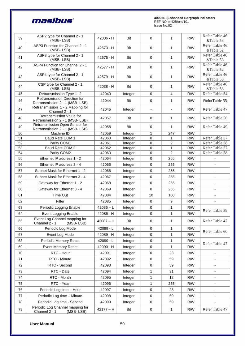
User Manual 59
40005E (Enhanced Bargraph Indicator) REF NO: m42B/om/101 Issue No:02
39 ASP2 type for Channel 2 - 1
(MSB- LSB) 42036 - H Bit 0 1 R/W
Refer Table 46
&Table 53
40 ASP3 Function for Channel 2 - 1
(MSB- LSB) 42573 - H Bit 0 1 R/W
Refer Table 46
&Table 52
41 ASP3 type for Channel 2 - 1
(MSB- LSB) 42575 - H Bit 0 1 R/W
Refer Table 46
&Table 53
42 ASP4 Function for Channel 2 - 1
(MSB- LSB) 42577 - H Bit 0 1 R/W
Refer Table 46
&Table 52
43 ASP4 type for Channel 2 - 1
(MSB- LSB) 42579 - H Bit 0 1 R/W
Refer Table 46
&Table 53
44 CSP type for Channel 2 - 1
(MSB- LSB) 42038 - H Bit 0 1 R/W
Refer Table 46
&Table 53
45 Retransmission Type 1- 2 42040 Integer 0 4 R/W Refer Table 54
46 Retransmission Direction for
Retransmission 2 - 1 (MSB- LSB) 42044 Bit 0 1 R/W ReferTable 55
47 Retransmission 1 - 2 Mapping for
Channel 2 - 1 42045 Integer - - R/W Refer Table 47
48 Retransmission Value for
Retransmission 2 - 1 (MSB- LSB) 42057 Bit 0 1 R/W Refer Table 56
49 Retransmission Open Sensor for Retransmission 2 - 1 (MSB- LSB)
42058 Bit 0 1 R/W Refer Table 49
50 Machine ID 42059 Integer 1 247 R/W
51 Baud Rate COM 1 42060 Integer 0 1 R/W Refer Table 57
52 Parity COM1 42061 Integer 0 2 R/W Refer Table 58
53 Baud Rate COM 2 42062 Integer 0 1 R/W Refer Table 57
54 Parity COM2 42063 Integer 0 2 R/W Refer Table 58
55 Ethernet IP address 1 - 2 42064 Integer 0 255 R/W -
56 Ethernet IP address 3 - 4 42065 Integer 0 255 R/W -
57 Subnet Mask for Ethernet 1 - 2 42066 Integer 0 255 R/W -
58 Subnet Mask for Ethernet 3 - 4 42067 Integer 0 255 R/W -
59 Gateway for Ethernet 1 - 2 42068 Integer 0 255 R/W -
60 Gateway for Ethernet 3 - 4 42069 Integer 0 255 R/W -
61 Time Out 42084 Integer 10 100 R/W -
62 Filter 42085 Integer 0 9 R/W -
63 Periodic Logging Enable 42086 – L Integer 0 1 R/W Refer Table 59
64 Event Logging Enable 42086 - H Integer 0 1 R/W
65 Event Log Channel mapping for Channel 2 - 1 (MSB- LSB)
42087 – H Bit 0 1 R/W Refer Table 47
66 Periodic Log Mode 42089 - L Integer 0 1 R/W Refer Table 60
67 Event Log Mode 42089 - H Integer 0 1 R/W
68 Periodic Memory Reset 42090 - L Integer 0 1 R/W Refer Table 47
69 Event Memory Reset 42090 - H Integer 0 1 R/W
70 RTC - Hour 42091 Integer 0 23 R/W -
71 RTC - Minute 42092 Integer 0 59 R/W -
72 RTC - Second 42093 Integer 0 59 R/W -
73 RTC - Date 42094 Integer 1 31 R/W -
74 RTC - Month 42095 Integer 1 12 R/W -
75 RTC - Year 42096 Integer 1 255 R/W -
76 Periodic Log time – Hour 42097 Integer 0 23 R/W -
77 Periodic Log time – Minute 42098 Integer 0 59 R/W -
78 Periodic Log time - Second 42099 Integer 0 59 R/W -
79 Periodic Log Channel mapping for Channel 2 - 1 (MSB- LSB)
42177 – H Bit 0 1 R/W Refer Table 47
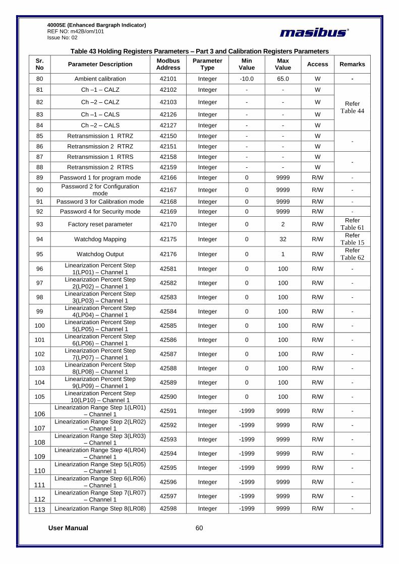
User Manual 60
40005E (Enhanced Bargraph Indicator) REF NO: m42B/om/101 Issue No: 02
Table 43 Holding Registers Parameters – Part 3 and Calibration Registers Parameters
Sr. No
Parameter Description Modbus Address
Parameter Type
Min Value
Max Value
Access Remarks
80 Ambient calibration 42101 Integer -10.0 65.0 W -
81 Ch –1 – CALZ 42102 Integer - - W
Refer
Table 44
82 Ch –2 – CALZ 42103 Integer - - W
83 Ch –1 – CALS 42126 Integer - - W
84 Ch –2 – CALS 42127 Integer - - W
85 Retransmission 1 RTRZ 42150 Integer - - W -
86 Retransmission 2 RTRZ 42151 Integer - - W
87 Retransmission 1 RTRS 42158 Integer - - W -
88 Retransmission 2 RTRS 42159 Integer - - W
89 Password 1 for program mode 42166 Integer 0 9999 R/W -
90 Password 2 for Configuration
mode 42167 Integer 0 9999 R/W -
91 Password 3 for Calibration mode 42168 Integer 0 9999 R/W -
92 Password 4 for Security mode 42169 Integer 0 9999 R/W -
93 Factory reset parameter 42170 Integer 0 2 R/W Refer
Table 61
94 Watchdog Mapping 42175 Integer 0 32 R/W Refer
Table 15
95 Watchdog Output 42176 Integer 0 1 R/W Refer
Table 62
96 Linearization Percent Step
1(LP01) – Channel 1 42581 Integer 0 100 R/W -
97 Linearization Percent Step
2(LP02) – Channel 1 42582 Integer 0 100 R/W -
98 Linearization Percent Step
3(LP03) – Channel 1 42583 Integer 0 100 R/W -
99 Linearization Percent Step
4(LP04) – Channel 1 42584 Integer 0 100 R/W -
100 Linearization Percent Step
5(LP05) – Channel 1 42585 Integer 0 100 R/W -
101 Linearization Percent Step
6(LP06) – Channel 1 42586 Integer 0 100 R/W -
102 Linearization Percent Step
7(LP07) – Channel 1 42587 Integer 0 100 R/W -
103 Linearization Percent Step
8(LP08) – Channel 1 42588 Integer 0 100 R/W -
104 Linearization Percent Step
9(LP09) – Channel 1 42589 Integer 0 100 R/W -
105 Linearization Percent Step
10(LP10) – Channel 1 42590 Integer 0 100 R/W -
106 Linearization Range Step 1(LR01)
– Channel 1 42591 Integer -1999 9999 R/W -
107 Linearization Range Step 2(LR02)
– Channel 1 42592 Integer -1999 9999 R/W -
108 Linearization Range Step 3(LR03)
– Channel 1 42593 Integer -1999 9999 R/W -
109 Linearization Range Step 4(LR04)
– Channel 1 42594 Integer -1999 9999 R/W -
110 Linearization Range Step 5(LR05)
– Channel 1 42595 Integer -1999 9999 R/W -
111 Linearization Range Step 6(LR06)
– Channel 1 42596 Integer -1999 9999 R/W -
112 Linearization Range Step 7(LR07)
– Channel 1 42597 Integer -1999 9999 R/W -
113 Linearization Range Step 8(LR08) 42598 Integer -1999 9999 R/W -
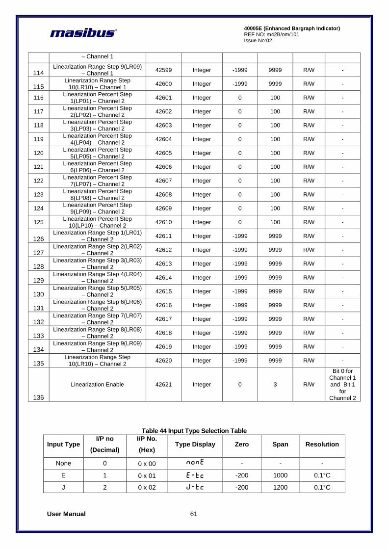
User Manual 61
40005E (Enhanced Bargraph Indicator) REF NO: m42B/om/101 Issue No:02
– Channel 1
114 Linearization Range Step 9(LR09)
– Channel 1 42599 Integer -1999 9999 R/W -
115 Linearization Range Step
10(LR10) – Channel 1 42600 Integer -1999 9999 R/W -
116 Linearization Percent Step
1(LP01) – Channel 2 42601 Integer 0 100 R/W -
117 Linearization Percent Step
2(LP02) – Channel 2 42602 Integer 0 100 R/W -
118 Linearization Percent Step
3(LP03) – Channel 2 42603 Integer 0 100 R/W -
119 Linearization Percent Step
4(LP04) – Channel 2 42604 Integer 0 100 R/W -
120 Linearization Percent Step
5(LP05) – Channel 2 42605 Integer 0 100 R/W -
121 Linearization Percent Step
6(LP06) – Channel 2 42606 Integer 0 100 R/W -
122 Linearization Percent Step
7(LP07) – Channel 2 42607 Integer 0 100 R/W -
123 Linearization Percent Step
8(LP08) – Channel 2 42608 Integer 0 100 R/W -
124 Linearization Percent Step
9(LP09) – Channel 2 42609 Integer 0 100 R/W -
125 Linearization Percent Step
10(LP10) – Channel 2 42610 Integer 0 100 R/W -
126 Linearization Range Step 1(LR01)
– Channel 2 42611 Integer -1999 9999 R/W -
127 Linearization Range Step 2(LR02)
– Channel 2 42612 Integer -1999 9999 R/W -
128 Linearization Range Step 3(LR03)
– Channel 2 42613 Integer -1999 9999 R/W -
129 Linearization Range Step 4(LR04)
– Channel 2 42614 Integer -1999 9999 R/W -
130 Linearization Range Step 5(LR05)
– Channel 2 42615 Integer -1999 9999 R/W -
131 Linearization Range Step 6(LR06)
– Channel 2 42616 Integer -1999 9999 R/W -
132 Linearization Range Step 7(LR07)
– Channel 2 42617 Integer -1999 9999 R/W -
133 Linearization Range Step 8(LR08)
– Channel 2 42618 Integer -1999 9999 R/W -
134 Linearization Range Step 9(LR09)
– Channel 2 42619 Integer -1999 9999 R/W -
135 Linearization Range Step
10(LR10) – Channel 2 42620 Integer -1999 9999 R/W -
136
Linearization Enable 42621 Integer 0 3 R/W
Bit 0 for Channel 1 and Bit 1
for Channel 2
Table 44 Input Type Selection Table
Input Type I/P no
(Decimal)
I/P No.
(Hex) Type Display Zero Span Resolution
None 0 0 x 00 none - - -
E 1 0 x 01 E-Tc -200 1000 0.1°C
J 2 0 x 02 J-tc -200 1200 0.1°C
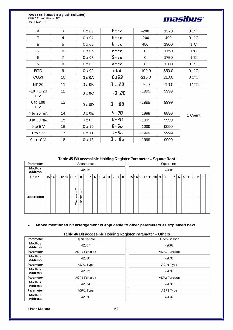
User Manual 62
40005E (Enhanced Bargraph Indicator) REF NO: m42B/om/101 Issue No: 02
K 3 0 x 03 K-tc -200 1370 0.1°C
T 4 0 x 04 T-tc -200 400 0.1°C
B 5 0 x 05 B-tc 450 1800 1°C
R 6 0 x 06 R-tc 0 1750 1°C
S 7 0 x 07 S-tc 0 1750 1°C
N 8 0 x 08 n-tc 0 1300 0.1°C
RTD 9 0 x 09 RTD -199.9 850.0 0.1°C
CU53 10 0 x 0A Cu53 -210.0 210.0 0.1°C
NI120 11 0 x 0B N.120 -70.0 210.0 0.1°C
-10 TO 20 mV
12 0 x 0C -10.20
-1999 9999
1 Count
0 to 100 mV
13 0 x 0D 0-100
-1999 9999
4 to 20 mA 14 0 x 0E 4-20 -1999 9999
0 to 20 mA 15 0 x 0F 0-20 -1999 9999
0 to 5 V 16 0 x 10 0-5V -1999 9999
1 to 5 V 17 0 x 11 1-5V -1999 9999
0 to 10 V 18 0 x 12 0.10V -1999 9999
Table 45 Bit accessible Holding Register Parameter – Square Root
Parameter Square root
Square root
Modbus Address
42002 42003
Bit No. 15 14 13 12 11 10 9 8
7 6 5 4 3 2 1 0 15 14 13 12 11 10 9 8
7 6 5 4 3 2 1 0
Description - - - - - -
Channel – 2
Channel – 1
- - - - - - - - - - - - - - - - - - - - - - - - - -
Above mentioned bit arrangement is applicable to other parameters as explained next .
Table 46 Bit accessible Holding Register Parameter – Others
Parameter Open Sensor
Open Sensor
Modbus Address
42007 42008
Parameter ASP1 Function ASP1 Function
Modbus Address
42030 42031
Parameter ASP1 Type
ASP1 Type
Modbus Address
42032 42033
Parameter ASP2 Function
ASP2 Function
Modbus Address
42034 42035
Parameter ASP2 Type
ASP2 Type
Modbus Address
42036 42037
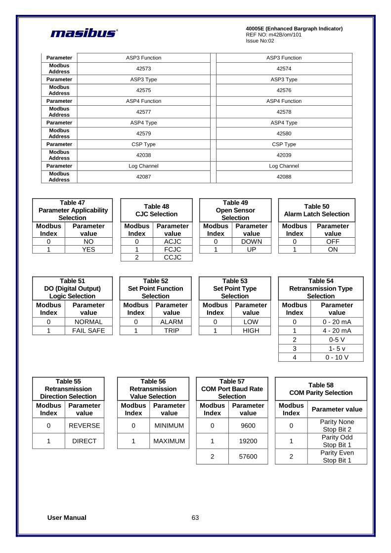
User Manual 63
40005E (Enhanced Bargraph Indicator) REF NO: m42B/om/101 Issue No:02
Parameter ASP3 Function
ASP3 Function
Modbus Address
42573 42574
Parameter ASP3 Type
ASP3 Type
Modbus Address
42575 42576
Parameter ASP4 Function
ASP4 Function
Modbus Address
42577 42578
Parameter ASP4 Type
ASP4 Type
Modbus Address
42579 42580
Parameter CSP Type
CSP Type
Modbus Address
42038 42039
Parameter Log Channel
Log Channel
Modbus Address
42087 42088
Table 47 Parameter Applicability
Selection
Table 48 CJC Selection
Table 49 Open Sensor
Selection
Table 50 Alarm Latch Selection
Modbus Index
Parameter value
Modbus Index
Parameter value
Modbus Index
Parameter value
Modbus Index
Parameter value
0 NO
0 ACJC
0 DOWN
0 OFF
1 YES
1 FCJC
1 UP
1 ON
2 CCJC
Table 51 DO (Digital Output)
Logic Selection
Table 52 Set Point Function
Selection
Table 53 Set Point Type
Selection
Table 54 Retransmission Type
Selection
Modbus Index
Parameter value
Modbus Index
Parameter value
Modbus Index
Parameter value
Modbus Index
Parameter value
0 NORMAL
0 ALARM
0 LOW
0 0 - 20 mA
1 FAIL SAFE
1 TRIP
1 HIGH
1 4 - 20 mA
2 0-5 V
3 1- 5 v
4 0 - 10 V
Table 55 Retransmission
Direction Selection
Table 56 Retransmission Value Selection
Table 57 COM Port Baud Rate
Selection
Table 58 COM Parity Selection
Modbus Index
Parameter value
Modbus Index
Parameter value
Modbus Index
Parameter value
Modbus Index
Parameter value
0 REVERSE
0 MINIMUM
0 9600
0 Parity None Stop Bit 2
1 DIRECT
1 MAXIMUM
1 19200
1 Parity Odd Stop Bit 1
2 57600
2 Parity Even Stop Bit 1

User Manual 64
40005E (Enhanced Bargraph Indicator) REF NO: m42B/om/101 Issue No: 02
Table 59
Table 60
Table 61
Table 62
Logging Enable Selection
Log Mode Selection
Factory Reset Parameters
WatchDog Output
Modbus Index
Parameter value
Modbus Index
Parameter value
Modbus Index
Parameter value
Modbus Index
Parameter value
0 STOP
0 HOLD
0 Calibration
Values 0 Disable
1 START
1 OVERLAP
1 Parameters
Values 1 Enable
2 All Values
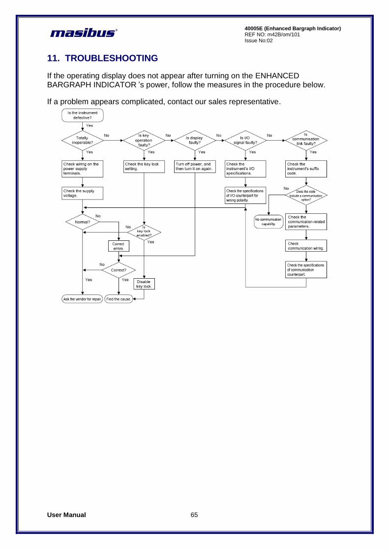
User Manual 65
40005E (Enhanced Bargraph Indicator) REF NO: m42B/om/101 Issue No:02
11. TROUBLESHOOTING
If the operating display does not appear after turning on the ENHANCED BARGRAPH INDICATOR ‟s power, follow the measures in the procedure below.
If a problem appears complicated, contact our sales representative.
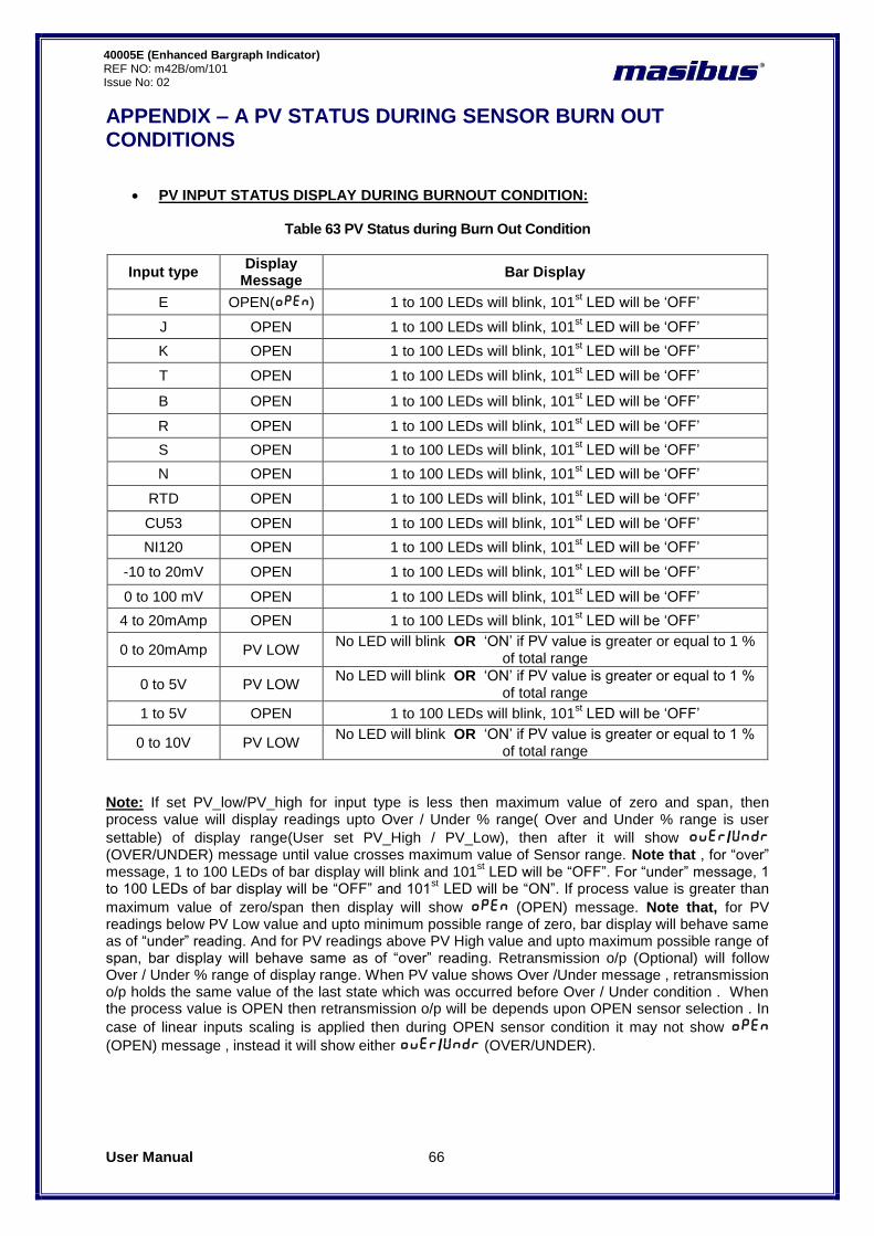
User Manual 66
40005E (Enhanced Bargraph Indicator) REF NO: m42B/om/101 Issue No: 02
APPENDIX – A PV STATUS DURING SENSOR BURN OUT CONDITIONS
PV INPUT STATUS DISPLAY DURING BURNOUT CONDITION:
Table 63 PV Status during Burn Out Condition
Input type Display
Message Bar Display
E OPEN(oPEn) 1 to 100 LEDs will blink, 101st LED will be „OFF‟
J OPEN 1 to 100 LEDs will blink, 101st LED will be „OFF‟
K OPEN 1 to 100 LEDs will blink, 101st LED will be „OFF‟
T OPEN 1 to 100 LEDs will blink, 101st LED will be „OFF‟
B OPEN 1 to 100 LEDs will blink, 101st LED will be „OFF‟
R OPEN 1 to 100 LEDs will blink, 101st LED will be „OFF‟
S OPEN 1 to 100 LEDs will blink, 101st LED will be „OFF‟
N OPEN 1 to 100 LEDs will blink, 101st LED will be „OFF‟
RTD OPEN 1 to 100 LEDs will blink, 101st LED will be „OFF‟
CU53 OPEN 1 to 100 LEDs will blink, 101st LED will be „OFF‟
NI120 OPEN 1 to 100 LEDs will blink, 101st LED will be „OFF‟
-10 to 20mV OPEN 1 to 100 LEDs will blink, 101st LED will be „OFF‟
0 to 100 mV OPEN 1 to 100 LEDs will blink, 101st LED will be „OFF‟
4 to 20mAmp OPEN 1 to 100 LEDs will blink, 101st LED will be „OFF‟
0 to 20mAmp PV LOW No LED will blink OR „ON‟ if PV value is greater or equal to 1 %
of total range
0 to 5V PV LOW No LED will blink OR „ON‟ if PV value is greater or equal to 1 %
of total range
1 to 5V OPEN 1 to 100 LEDs will blink, 101st LED will be „OFF‟
0 to 10V PV LOW No LED will blink OR „ON‟ if PV value is greater or equal to 1 %
of total range
Note: If set PV_low/PV_high for input type is less then maximum value of zero and span, then process value will display readings upto Over / Under % range( Over and Under % range is user
settable) of display range(User set PV_High / PV_Low), then after it will show oVER/UnDR (OVER/UNDER) message until value crosses maximum value of Sensor range. Note that , for “over” message, 1 to 100 LEDs of bar display will blink and 101
st LED will be “OFF”. For “under” message, 1
to 100 LEDs of bar display will be “OFF” and 101st LED will be “ON”. If process value is greater than
maximum value of zero/span then display will show oPEn (OPEN) message. Note that, for PV readings below PV Low value and upto minimum possible range of zero, bar display will behave same as of “under” reading. And for PV readings above PV High value and upto maximum possible range of span, bar display will behave same as of “over” reading. Retransmission o/p (Optional) will follow Over / Under % range of display range. When PV value shows Over /Under message , retransmission o/p holds the same value of the last state which was occurred before Over / Under condition . When the process value is OPEN then retransmission o/p will be depends upon OPEN sensor selection . In
case of linear inputs scaling is applied then during OPEN sensor condition it may not show oPEn
(OPEN) message , instead it will show either oVER/UnDR (OVER/UNDER).
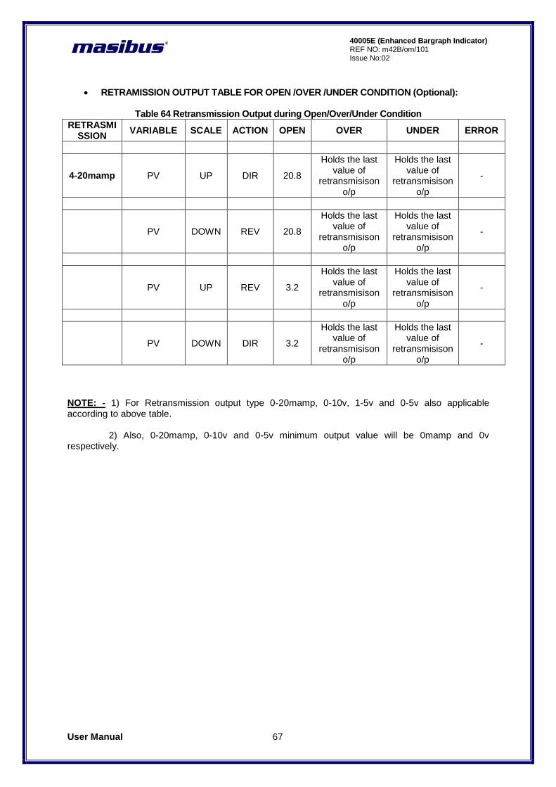
User Manual 67
40005E (Enhanced Bargraph Indicator) REF NO: m42B/om/101 Issue No:02
RETRAMISSION OUTPUT TABLE FOR OPEN /OVER /UNDER CONDITION (Optional):
Table 64 Retransmission Output during Open/Over/Under Condition
RETRASMISSION
VARIABLE SCALE ACTION OPEN OVER UNDER ERROR
4-20mamp PV UP DIR 20.8
Holds the last value of
retransmisison o/p
Holds the last value of
retransmisison o/p
-
PV DOWN REV 20.8
Holds the last value of
retransmisison o/p
Holds the last value of
retransmisison o/p
-
PV UP REV 3.2
Holds the last value of
retransmisison o/p
Holds the last value of
retransmisison o/p
-
PV DOWN DIR 3.2
Holds the last value of
retransmisison o/p
Holds the last value of
retransmisison o/p
-
NOTE: - 1) For Retransmission output type 0-20mamp, 0-10v, 1-5v and 0-5v also applicable according to above table. 2) Also, 0-20mamp, 0-10v and 0-5v minimum output value will be 0mamp and 0v respectively.
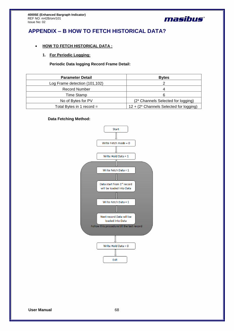
User Manual 68
40005E (Enhanced Bargraph Indicator) REF NO: m42B/om/101 Issue No: 02
APPENDIX – B HOW TO FETCH HISTORICAL DATA?
HOW TO FETCH HISTORICAL DATA : 1. For Periodic Logging:
Periodic Data logging Record Frame Detail:
Parameter Detail Bytes
Log Frame detection (101,102) 2
Record Number 4
Time Stamp 6
No of Bytes for PV (2* Channels Selected for logging)
Total Bytes in 1 record = 12 + (2* Channels Selected for logging)
Data Fetching Method:

User Manual 69
40005E (Enhanced Bargraph Indicator) REF NO: m42B/om/101 Issue No:02
Modbus Address for Periodic Data fetching:
Sr. No
Parameter Description Modbus Address
Parameter Type
Access Remarks
1 Data Fetched Periodic Log 42301-42375
Integer R -
2 Hold Data 42377 Integer R/W -
3 Fetch Data 42376 Integer R/W -
4 Total Periodic Records 42378-42379
Integer R 42378 [Higher byte] 42379[Lower Byte]
5 Log Roll Over counter for Overlap
Mode 42380 Integer R -
6 Fetch mode 42381 Integer R/W
Description :
o For Data logging Flash memory is used so data will be fetched in the form of multiple records. Flash page size is of 256 bytes.
o The record length is based on Channel number for log selection o So in from below equation we can get how many records we can get from 1 page i.e.
Records per page = (Integer) (256 / Total Bytes in 1 record)
o Example for Fetching data :
Example 1 : If we have selected 8 channels for periodic data logging so that Total Bytes in 1 record = 12 + (2 * 8) = 28 Record Per page = 256 / 28 = 9(Odd Number) So in this case for fetching data, follow below procedure: 1. Write Hold Data = 1
2. Write Fetch Data = 1
3. Data for first 4 records are loaded into data registers
4. Write Fetch Data = 1
5. Data for record number 5 to 9 will be loaded into data registers
6. Write Fetch data = 1
7. Data for record number 10 to 13 will be loaded into data registers
8. Write Fetch data = 1
9. Data for record number 14 to 18 will be loaded into data registers
10. So in same manner data registers will be filled with 4 records first and then 5 records.
11. After all data fetch Write Hold Data = 0.
Example 2 : If we have selected 24 channels for periodic data logging so that Total Bytes in 1 record = 12 + (2 * 24) = 60 Record Per page = 256 / 60 = 4(Even Number) So in this case for fetching data follow below procedure: 1. Write Hold Data = 1 2. Write Fetch Data = 1 3. Data for first 2 records are loaded into data registers 4. Write Fetch Data = 1 5. Data for record number 3 - 4 will be loaded into data registers 6. Write Fetch data = 1
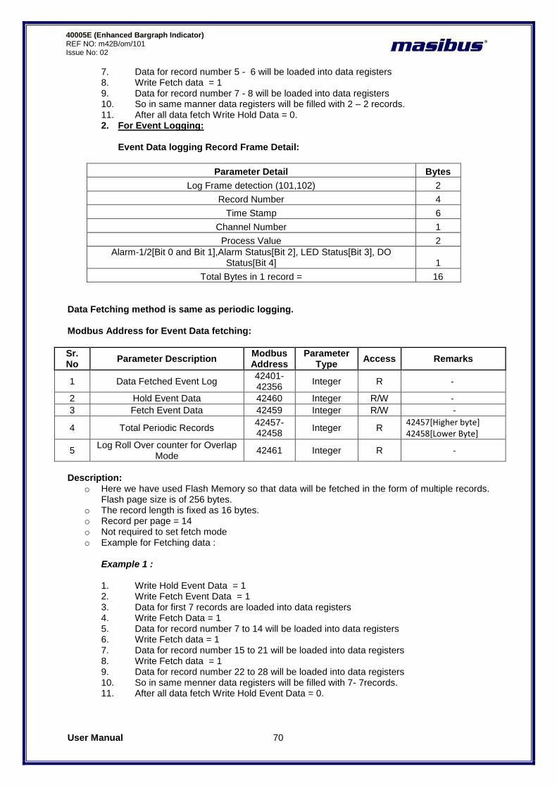
User Manual 70
40005E (Enhanced Bargraph Indicator) REF NO: m42B/om/101 Issue No: 02
7. Data for record number 5 - 6 will be loaded into data registers 8. Write Fetch data = 1 9. Data for record number 7 - 8 will be loaded into data registers 10. So in same manner data registers will be filled with 2 – 2 records. 11. After all data fetch Write Hold Data = 0. 2. For Event Logging:
Event Data logging Record Frame Detail:
Parameter Detail Bytes
Log Frame detection (101,102) 2
Record Number 4
Time Stamp 6
Channel Number 1
Process Value 2
Alarm-1/2[Bit 0 and Bit 1],Alarm Status[Bit 2], LED Status[Bit 3], DO Status[Bit 4] 1
Total Bytes in 1 record = 16
Data Fetching method is same as periodic logging. Modbus Address for Event Data fetching:
Sr. No
Parameter Description Modbus Address
Parameter Type
Access Remarks
1 Data Fetched Event Log 42401-42356
Integer R -
2 Hold Event Data 42460 Integer R/W -
3 Fetch Event Data 42459 Integer R/W -
4 Total Periodic Records 42457-42458
Integer R 42457[Higher byte] 42458[Lower Byte]
5 Log Roll Over counter for Overlap
Mode 42461 Integer R -
Description:
o Here we have used Flash Memory so that data will be fetched in the form of multiple records. Flash page size is of 256 bytes.
o The record length is fixed as 16 bytes. o Record per page = 14 o Not required to set fetch mode o Example for Fetching data :
Example 1 : 1. Write Hold Event Data = 1 2. Write Fetch Event Data = 1 3. Data for first 7 records are loaded into data registers 4. Write Fetch Data = 1 5. Data for record number 7 to 14 will be loaded into data registers 6. Write Fetch data = 1 7. Data for record number 15 to 21 will be loaded into data registers 8. Write Fetch data = 1 9. Data for record number 22 to 28 will be loaded into data registers 10. So in same menner data registers will be filled with 7- 7records. 11. After all data fetch Write Hold Event Data = 0.

User Manual 71
40005E (Enhanced Bargraph Indicator) REF NO: m42B/om/101 Issue No:02
REVISION HISTORY :
1. Version No. 01:
o Linearization Specification added. o Linearization parameter added in Menu parameters. o Linearization note added in calibration procedure. o Modbus parameters for Linearization added.
2. Version No. 02:
o Back Plate Wiring Details are added.
Masibus Automation & Instrumentation Pvt. Ltd.
Customer Support Division B/30, GIDC Electronics Estate,
Sector-25, Gandhinagar-382044, Gujarat, India
Ph: 91-079-23287275/23287276/23287277 Fax: 91-079-23287281
Email: [email protected]
Web: www.masibus.com


