Embed Size (px)
Citation preview
Distribution CategoryNuclear Energy (UC-940)
ANL/RERTR/TM-19CONF-9209266
ARGONNE NATIONAL LABORATORY9700 South Cass AvenueArgonne, Illinois 60439
Proceedings of the1992 International Meeting on
REDUCED ENRICHMENT FORRESEARCH AND TEST REACTORS
Roskilde, DenmarkSeptember 27-October 1, 1992
Karsten HaackProgram Chairman
Administrative Arrangements
Grethe ChristiansenAnni Lambaek F=insen
July 1993
DISTFMQUTTON OF TH» DOCUMENT «
The previous Reduced Enrichment for Research and Test Reactor meetingswere held at:
Argonne National Laboratory - November 1978
Saclay, France - December 1979
Argonne National Laboratory - November 1980
Juelich, FRG - September 1981
Argonne National Laboratory - November 1982
Tokai, Japan - October 1983
Argonne National Laboratory - October 1984
Petten, The Netherlands - October 1985
Gatlinburg, Tennessee - November 1986
Buenos Aires, Argentina - September 1987
San Diego, California - September 1988
Berlin, Germany - September 1989
Newport, Rhode Island - September 1990
Jakarta, Indonesia - November, 1991
Roskilde, Denmark - September, 1992
n
PREFACE
The 15th annual RERTR international meeting was organized by RispNational Laboratory in cooperation with the International AtomicEnergy Agency and Argonne National Laboratory.
Although odd-numbered RERTR international meetings are usuallyhosted by the U.S., conducting the meeting in Denmark provided theparticipants with an unique opportunity to visit the DR3 researchreactor. In operation since completion of the 1990 conversion, the DR3reactor has been operating at 10 MW with a full core of low enricheduranium silicide fuel elements. In addition, RERTR Programparticipants toured the local fuel element production plar.u. Thisplant has supplied the DR3 reactor with HEU, MEU, and a multitude ofother LEU fuel elements for more than 20 years.
The topics of the meeting were the following: National Programs,Fuel Fabrication, Licensing Aspects, States of Conversion, FuelTesting, and Fuel Cycle. The meeting was terminated by a Round TableDiscussion.
The meeting included an address to the U.S. Secretary of Energy,Admiral James D. Watkins. Expressing a deep concern stemming from thesituation involving the back-end of the fuel cycle, the non-U.S.participants agreed that such an speech was necessary. Many of theparticipants in the RERTR program had no means to complete their FuelCycle after the December 31, 1992 expiration of the U.S. Department ofEnergy's program for the reprocessing of foreign research and testreactor spent fuel. Luckily, the March 3, 1993 response from theUSDOE was encouraging in that the USDOE now proposes to renew itsreprocessing policy.
An additional letter was sent to the IAEA Deputy DirectorGeneral, Dr. Sueo Machi. This letter suggested that the IAEA takeover RERTR responsibilities on a global scale in order to minimize theuse of HEU in the world's research reactors.
The welcome address was given by Ris0's Scientific Director, Dr.Jprgen Kj ems .
The after-dinner speech at the Wednesday, September 30, 1992evening banquet was given by Professor Dr. Alan R. Mackintosh.
I would like to acknowledge the support and cooperation of theArgonne National Laboratory RERTR program members in helping to notonly prepare for and execute the meeting, but also ultimately publishthe proceedings.
I would also like to acknowledge the competent work of theorganizing committee members whose coordinated efforts contributed tothe successful nature of the 1992 RERTR international meeting.
Karsten HaackProgram Chairman
Hi
* I s : I i I | \ Si . ' S i j « 1 | | )
% i i i i % %- s s i s f S
1 I f i t- 1 ! ?. » S S »
3pii jljpipjjiii i Jj; iji1! ^inlnsiiB^MtBM'i I
•2 I!sillSiil«3ls ills5 ! s
! i f
s =•
it ! !. l I
' .i<5--;.-tI. -Ssrfl^a6
15TH INTERNATIONAL MEETING ON REDUCED hNRICHMENT
FOR RESEARCH AND TEST REACTORS
SEPTEMBER 27 TO OCTOBER 1, 1992 IN ROSKILDE, DENMARK
WELCOME ADDRESS TO PARTICIPANTS TO THE 15. RERTR-CONFERENCEREDUCED ENRICHMENT FOR RESEARCH AND TEST REACTORS
Jorgen KjemsRis0 National LaboratoryDK-4000 Roskilde, Denmark
Ladies and Gentleman,
On behalf of Ris0 National Laboratory I should like to welcomeyou all to Roskilde and to the 15th meeting on the program forthe use of Reduced Enrichment for Research and Test Reactors, forwhich you use the acronym RERTR - impossible to pronounce!
We are happy to see that so many of our colleagues have been ableto attend the meeting. I am told that 18 nations are representedcovering more than 40 organizations and agencies.
In particular we welcome the new attendees to these meetings fromthe eastern european nations and from the developing countries.
The meeting has been organized in cooperation with theInternational Atomic Energy Agency and I should like to thankboth the agency and the other collaborators for their efforts inthe support and planning of this meeting.
Let me quickly introduce myself, I am a solid state physicist bytraining, and - up until a few years ago- I have devoted myscientific career to the use of neutron scattering to solveproblems in solid state physics, chemistry and biology.
I can therefore appreciate the importance of the scientificcontributions that flow from the continued use of research andtest reactors around the globe.
Many of these installations have reached a mature age - our ownreactor DR 3 is still going r;trong in its 3 3rd year ofoperations. But - despite their age - they remain much neededtools for the advancement of both science and technology.
This has recently been illustrated to us by the fact that the DR3 reactor has been selected for the European program for commonuse of Large Scientific Installations. Under this program some50 European scientific user groups will gain access to theneutron beam facilities at the DR 3 reactor.
Isotope production, silicon transmutation and activation analysisare other important uses we make of the DR 3 reactor.
This illustrates the use of the DR 3 reactor. The research andtest reactors in your countries have similar tasks, which - I amsure - are performed with similar professional pride and care.
Common for all is the desireand requirement for safe and reliableoperation of these facilities, including all aspects of the fuelcycle.
This brings me to the issue of non-proliferation, and to theRERTR-program, which I see as a significant contribution to theglobal control of fissile, material.
Early on, Rise National Laboratory has adapted the RERTR-programstrategy for our own fuel cycle, and at this meeting you willhear reports that summarizes our experiences, including:
- the development the LEU-elements and of our productioncapability,
- the production of the LEU-elements for the DR 3 reactorand others,
- the process of converting the DR 3 reactor for LEU-operation. This was completed in december of 1990 - and wewere proud to be among the first in the world to achievethis milestone,
- the collaboration through IAEA on guidebooks for thetechnical conversion and for the approval procedures to beused by the authorities.
But alas - even though all of these achievements representsignificant steps in the right direction - one cannot claim thatthe fuel cycle situation for research reactors is fullysatisfactory.
On the global scale we have to recognize the political changesthat have occurred in eastern europe and elsewhere.
These have changed the basis for the recommendations that cameout of the 1978-1980 International Nuclear Fuel Cycle Evaluationand for the RERTR-program.
It is appropriate to reassess these recommendations in the lightof our present situation.
Here I should like to point once again to the InternationalAtomic Energy Agency, and ask that the promotion, review andmonitoring of the RERTR-program is given sufficient priorityamong all the other important tasks of the agency - connectedwith the Non-Proliferation Treaty.

As I mentioned earlier, the IAEA has played an important role inthe planning of this meeting, and I hope that it can be extendedto future meetings and to the time in between.
This is on way in which the IAEA can contribute to the continuedsuccess of the RERTR-program.
Another outstanding issue of immediate concern is the completionof the fuel cycle. Here I refer to the handling, reprocessing andstorage of the spent fuel and associated waste.
In this area we need increased international collaboration on abilateral as well as a regional basis, - and also betweencontinents.
Denmark - like several other nations - have chosen net to usenuclear power for electricity production. Hence we will probablynot develop capabilities in these areas - in foreseeable future.
Presently, we are dependent on the solutions and opportunitiesother nations can offer within the scope of collaborativeagreements.
I hope that this meeting also can be used to discuss these issuesand that we can develop ideas for workable common solutions, thatserves everybody's interests.
These are tough issues with both political and technicalramifications. The only way to make progress is through dialogue.
In this respect, these meetings offer unique occasions forfruitful discussions between reactor operators, reactor users,fuel manufacturers, fuel and waste handlers and transporters aswell as representatives from licensing and other authorities.
I trust that you will use this occasion where you can exchangeviews and experiences gained around the globe.
This will allow each of us to continue improving our dailyperformance and to make new contributions to the safe andreliable operation of research and test reactors.
In this spirit I welcome all of you to Roskilde and wish you asuccessful meeting.
*****
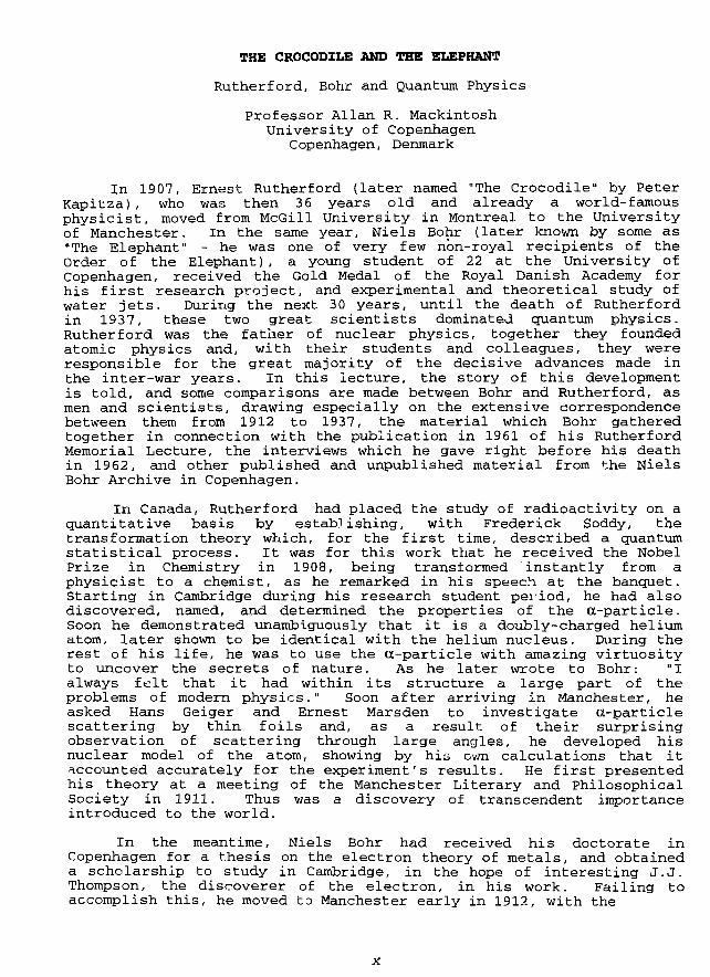
THE CROCODILE AND THE ELEPHANT
Rutherford, Bohr and Quantum Physics
Professor Allan R. MackintoshUniversity of Copenhagen
Copenhagen, Denmark
In 1907, Ernest Rutherford (later named "The Crocodile" by PeterKapitza) , who was then 36 years old and already a world-famousphysicist, moved from McGill University in Montreal to the Universityof Manchester. In the same year, Niels Bohr (later known by some as"The Elephant" - he was one of very few non-royal recipients of theOrder of the Elephant) , a young student of 22 at the University ofCopenhagen, received the Gold Medal of the Royal Danish Academy forhis first research project, and experimental and theoretical study ofwater jets. During the next 30 years, until the death of Rutherfordin 1937, these two great scientists dominated quantum physics.Rutherford was the father of nuclear physics, together they foundedatomic physics and, with their students and colleagues, they wereresponsible for the great majority of the decisive advances made inthe inter-war years. In this lecture, the story of this developmentis told, and some comparisons are made between Bohr and Rutherford, asmen and scientists, drawing especially on the extensive correspondencebetween them from 1912 to 1937, the material which Bohr gatheredtogether in connection with the publication in 1961 of his RutherfordMemorial Lecture, the interviews which he gave right before his deathin 1962, and other published and unpublished material from the NielsBohr Archive in Copenhagen.
In Canada, Rutherford had placed the study of radioactivity on aquantitative basis by establishing, with Frederick Soddy, thetransformation theory which, for the first time, described a quantumstatistical process. It was for this work that he received the NobelPrize in Chemistry in 1908, being transformed instantly from aphysicist to a chemist, as he remarked in his speech at the banquet.Starting in Cambridge during his research student period, he had alsodiscovered, named, and determined the properties of the a-particle.Soon he demonstrated unambiguously that it is a doubly-charged heliumatom, later shown to be identical with the helium nucleus. During therest of his life, he was to use the a-particle with amazing virtuosityto uncover the secrets of nature. As he later wrote to Bohr: "Ialways felt that it had within its structure a large part of theproblems of modern physics." Soon after arriving in Manchester, heasked Hans Geiger and Ernest Marsden to investigate a-particlescattering by thin foils and, as a result of their surprisingobservation of scattering through large angles, he developed hisnuclear model of the atom, showing by his own calculations that itaccounted accurately for the experiment's results. He first presentedhis theory at a meeting of the Manchester Literary and PhilosophicalSociety in 1911. Thus was a discovery of transcendent importanceintroduced to the world.
In the meantime, Niels Bohr had received his doctorate inCopenhagen for a thesis on the electron theory of metals, and obtaineda scholarship to study in Cambridge, in the hope of interesting J.J.Thompson, the discoverer of the electron, in his work. Failing toaccomplish this, he moved to Manchester early in 1912, with the
intention of learning the techniques of radioactivity from Rutherford.He rapidly became fully convinced of the validity and significance ofthe Rutherford atom, more so perhaps than even Rutherford himself, andbegan to try and explain its stability and properties on the basis ofMax Planck's quantum of action. On returning to Denmark and learningof Balmer's formula for the frequencies of the spectral lines inHydrogen, he postulated in 1913 his atomic modal, with quantum rulesdetermining stationary states, whose energy differences govern thespectral frequencies through Planck's constant. These fundamentalconcepts still lie at the basis of our understanding of atomicstructure. Bohr's model was given decisive support by the brilliantexperiments of Henry Mosely, soon thereafter tragically killed in theFirst World War, who used X-ray spectra to determine the atomicnumber, the electric charge on the nuclei of the atoms.
Bohr returned to Manchester as a Reader in 1914, at the beginningof the war, to teach and develop his atomic theory, but went home toDenmark in 1916 to become Professor of Theoretical Physirs at theUniversity of Copenhagen. Under extremely difficult conditions,Rutherford managed to continue a little research during the war and ina letter to Bohr at the end of 1917 announced "results which, I think,will ultimately prove of great importance." By bombarding nitrogenwith cc-particles.. he carried out the first controlled transformationof a nucleus, creating protons and, as was later proved by PatrickBlackett, oxygen nuclei. In 1919, he moved to Cavendish Laboratory,Cambridge, where he and his colleagues, particularly James Chadwickand Charles Ellis, continued to explore the nucleus. Many nucleartransmutations were produced by bombardment with cc-particles, andtheir anomalous scattering led to the discovery of the strong nuclearforce. Just before the war, Chadwick had shown that the electronsemitted in radioactive S-decay do not have a unique energy, but rathera continuous distribution. This surprising result was confirmed byEllis who, in a series of elegant experiments in the 1920's, exploredthoroughly the nature of S-and y-emission and laid the foundations ofnuclear spectroscopy. The continuous 5-spectrum required a radicalexplanation; either energy is not conserved in the nuclear process, ahypothesis favored for a while by Bohr, or it is carried away byanother, elusive particle, Wolfgang Pauli's neutrino, which was indeedlater proved to exist.
After his return to Denmark, Bohr was for a number of yearsoccupied with using the quantum theory and his correspondenceprinciple to explain the structure of atoms and the periodic table ofthe elements, thus providing the basis for quantum chemistry. Thiswork culminated at about the time he received the Ncbel Prize in 1922,simultaneously with the discovery of the element hafnium, whoseproperties he had predicted, by his colleagues Dirk Costerr and GeorgeHevesy. He had first met the latter in Rutherford's laboratory inManchester in 1912, and they remained close friends for the rest oftheir lives. Thereafter the inadequacies of the old quantum theorybecame increasingly apparant, until the deepening crisis of atomicphysics was resolved through the discovery of quantum mechanics byWernwer Heisenberg, Bohr's young associate. As it is apparant fromhis letters, Bohr's relationship with Heisenberg was reminiscent ofthat of Rutherford to himself in earlier years; he described him, forexample, as "an ingenious (sic) and sympathetic young man indeed."Their later partial estrangement due to events during the Second Warwas therefore particularly painful for both of them. Bohr played
XI
little direct part in the establishment of quantum mechanics, thoughhe took a keen interest in the revolutionary advances made by hisyounger colleagues, particularly Heisenberg and Paul Dirac. However,he became increasingly interested in the philosophical foundations ofthe theory, and his principle of complementarily formed the basis forthe "Copenhagen interpretation" which is generally accepted today. Itwas not however accepted by a number of the distinguished pioneers ofthe quantum theory, notably Albert Einstein, with whom Bohr conducteda dialogue, based on deep disagreement and an equally deep mutualrespect, until Einstein's death.
The research on nuclear physics in the Cavendish Laboratoryculminated in the annus mirabilis of 1932, 'when Chadwick discoveredthe neutron , John Cockcroft and Ernest Walton carried out the firsttransmutation of nuclei by artificially ...orfil srarer?, particle?2,producing a-particles from lithium by bombardment with protons, andBlackett and Occhialini observed the electron-positron pairs which hadbeen predicted by Dirac. Rutherford's willingness to countenance theconstruction of the Cockcroft-W=»lton accelerator, which was terriblyexpensive by his standards, was. strongly influenced by the argumentsof George Gamov, who came on a visit Jrom Copenhagen at the suggestionof Bohr. Gamov had shown that particle of even moderate energy shouldbe able to induce nuclear transmutations by quantum mechanicaltunneling. These and subsequent developments showed that quantummechanics could indeed be applied to the nucleus, after all, and Bohrrapidly showed an interest in doing so. His scientific contracts toRutherford, which had been relatively sparse during the 1920's becauseof divergent interests, were thereby again intensified. He used hisearly experience with liquids to develop the liquid-drop model of thenucleus, and explained nuclear reactions as proceeding via theformation of a compound nucleus. It was on this subject that he gavehis last course of lectures in Cambridge at the invitation ofRutherford in 1936.
After the momentous events of 1932, nuclear physics of thehighest quality continued to be performed in the Cavendish Laboratory.In 1934, for example, Rutherford made his last great discovery,, withMarcus Oliphant and Paul Harteck, of the fusion of the nuclei of heavyhydrogen - deuterons - to yield the new isotopes tritium and helium-3,plus the energy which may power electricity stations in the future.Whereas, before this time, almost every significant advance in nuclearphysics had been made either by Rutherford or his colleagues, thecenter of activity diffused away from Cambridge thereafter.Artificial radioactivity was discovered by Irene Curie and FredericJoliot in Paris, Ernest Lawrence's cyclotron in Berkeley pointed theway towards the future of nuclear and particle physics, and EnricoFermi in Rome used slow-neutron capture to produce a variety ofnuclear reactions, including the synthesis of radioactive isotopes ofmany elements, and fission, although he did not identify it as such.In the middle 1930's, most of Rutherford's younger colleagues left toestablish their own departments and, at his untimely death in 1937,the Cavendish Laboratory began to look for new fields to conquer.Rutherford just failed to experience the discovery of fission, whenhis former student Otto Hahn and Fritz Strassman identified Barium asa product of the bombardment of uranium with neutrons, and LiseMeitner and Ctto Frisch, colleagues of Hahn and Bohr respectively,showed that its presence was due to the disintegration of the uraniumnucleus. Bohr and John Wheeler developed a theory of fission based on
the compound-nucleus model, just before the outbreak of war brought toa close this most remarkable era in the history of physics.
After the war, Bohr performed little physics, but played anextremely important role, nationally and internationally as an elderstatesman of science. He and Rutherford, who had already establishedsuch a position at the time of his death, would have made asformidable a combination in science policy as they had earlier inresearch. Bohr attempted to curb the menace of nuclear weapons by hisOpen Letter to the United Nations, which had rather little politicalinfluence at the time, but which contains many useful lessons for thepresent period of East-West rapprochement. He worked actively andeffectively for the establishment of CERN in Geneva, and the RisaNational Laboratory and NORDITA, the Nordic Institute for TheoreticalPhysics, in Denmark. He presided over the change in the generationsat his own institute. Under the leadership of his son, Aage, and BenMottelson, supported by many distinguished colleagues, the Niels Bohrinstitute maintained its position as a world leader in nuclearphysics. By the time of Niels Bohr's death in 1962, Danish physicswas on the path to new successes, with a quality and breadth unusualfor such a small country.
The backgrounds, personalities, and styles of these twoscientific giants afford interesting comparisons and contrasts. Theywere both born in small countries, almost diametrically opposite onthe globe, but their attitudes towards their homelands were quitodifferent. Rutherford realized early in his career that it would benecessary to travel in order to be at the center of scientificactivity, and he never seriously considered a permanent return to NewZealand. Bohr, on the other hand, was only really at home in Denmarkand never seriously considered emigration, despite many attractiveoffers. He responded for example to Rutherford's offer of a Chair inManchester by writing: "The fact is that I feel that I have morallypledged myself to do what I can to help in the development of thescientific physical research here in Denmark." Bohr's background wasin the comfortable, academic middle-class while Rutherford was amember of a large pioneering family, whose survival and modestprosperity was based on extremely hard work. Their differencescreated no barriers between them, however, nor did they shown anysigns of class-consciousness in their dealings with others. They bothhad excellent, though dissimilar educations. Their wives, who werevery differenc, provided an essential practical and emotional supportfrom the beginning of their careers. They both survived theirhusbands by many years. The letters written from England by the twoyoung scientists to thrir fiances provides a rich source ofinformation on their early struggles and successes.
At first sight, there could hardly have been a stronger contrastbetween their personalties. Bohr was soft in voice and manner, whileRutherford was loud. Beneath the surface, however, they were quitesimilar. Chadwick's description of Rutherford applied to both ofthem:
He knew his worth, but he was and remained, amidst his manyhonors, innately modest. Pomposity and humbug he disliked,and he himself never presumed on his reputation or position.He treated his students, even the most junior, as brotherworkers in the same field.
Xlll
Their point of greatest similarity lay, however, in theiruncompromising determination to solve the scientific problems whichthey set themselves. Combined with a prodigious capacity for work andan exceptional insight into the workings of nature, this unswervingdevotion to their craft resulted in remarkable achievements. Theirscientific styles were characterized by an unerring instinct for theimportant problems, and the simplicity of the means by which theyobtained results of the greatest originality and significance. AsBohr put it, in a speech of thanks to Rutherford in Copenhagen. "If asingle word could be used to describe so vigorous and many-sid <l apersonality, it would certainly be 'simplicity'." Ruthev.forddiscovered, explored, and transformed the nucleus with the a-partic ..•=>and little more, and was not very enthusiastic about complexequipment, while Bohr founded atomic physics using Planck's quantumcombined with subtle and powerful arguments, rather than elaboratemathematics. Although they never published a joint paper, thecollaboration between them was one of the most important in thehistory of science. Not since the time of Tycho Brahe and Kepler hada young disciple taken the observations of a master and used them totransform our understanding of the universe.
Rutherford and Bohr were among the greatest of scientificteachers. Many of their students became eminent in their own rightand, with very few exceptions, all the most distinguished physicistsof the first half of the century were decisively influenced bycontacts with them. Chadwick wrote of Rutherford after his death, j"hecame to regard the training of students in methods of research as1 ofalmost equal importance to the advancement of knowledge." There is nodoubt that Bohr's style of intense but informal discussions with hisstudents and colleagues owed a great deal to his observations ofRutherford in Manchester in his own student days. They were bothmemorable lecturers but, whereas Rutherford impressed by his clarityand enthusiasm, Bohr inspired by his manifest searching after thetruth, despite a frequently impenetrable obscurity. Both werescientific leaders of the greatest importance, being at the centers ofgreat schools of physics. Surprisingly, Rutherford, theexperimentalist, was much less adept at obtaining financial supportthan was Bohr, the theoretician. He had a preference foruncomplicated equipment and had difficulty in sympathizing with orsupporting those with more elaborate ambitions. It was this traitwhich caused the disagreement with Chadwick, a nuclear physicistsecond to only Rutherford himself, which caused the former reluctantlyto leave Cambridge. Bohr, on the other hand, played the fund-raisinggame with consummate skill and was able to not only construct and manhis own institute, and equip it with the most modern apparatus(including the first operating cyclotron in Europe), but also to makea major contribution to the establishment of other institutions andactivities, including the first school of radiobiology under Hevesy.Through these initiatives, his influence on science in Denmark and inthe world was incalculable.
The voluminous literature about Rutherford and Bohr, andparticularly the testimony of those that knew them, providesconvincing evidence that they *rere not only great scientists, but alsogreat men. Their correspondence is full of examples of theirgenerosity towards others, and they both made major, demanding, andsuccessful efforts to assist the victims of Nazism. This should not,of course, be taken as implying that they were saints. They surely
xiv
had the same human weaknesses as the rest of mankind, but were moresuccessful than most in overcoming them. Their tremendous scientificauthority could, however, have an intimidating effect on their youngercolleagues. At the beginning of their long association, Rutherforddiscouraged Bohr from publishing his, perfectly correct and important,conclusions of the radioactive displacement laws and isotopes. Thereare a number of later examples wnere both, from the best of motives,inhibited the publication of important results or speculations.Nevertheless.. their colleagues or pupils spoke of them with thegreatest respect and affection. Notwithstanding his disenchantmentwith Rutherford's autocratic and penny-pinching attitude, Chadwiokconcluded his obituary:
All over the world, workers in radioactivity, nuclearphysics, and allied subjects regarded Rutherford as the greatauthority and paid him tribute of high admiration; but we, hisstudents, bore him also a very deep affection. The world mournsthe death of a great scientist, but we have lost our friend, ourcounsellor, our staff, and our leader.
All scientists can derive inspiration from their example; devotion tothe highest ideals of science may als•.. lead to humanity and wisdom.The lives of both Ernest Rutherford and Niels Bohr may be fittinglycharacterized by Bohr's last recorded words, "it is a very beautifulstory, because he took things very seriously."
xv
SESSION I
September 28, 1992
PROGRESS REPORTS ON NATIONAL PROGRAMMESChairman: H. Floto {Ris0 National Laboratory, Denmark)
THE RERTR PROGRAM: A STATUS REPORTA. Travelli, ANL
STATUS OF REDUCED ENRICHMENT PROGRAMS FORRESEARCH REACTORS IN JAPAN
K. Kanda and H. Nishihara, KURRIY. Futamura, E. Shirai, and T. Asaoka, JAERI 14
STATUS OF CANADIAN LOW-ENRICHED URANIUMCONVERSION PROGRAM
J.W. Schreader, S.J. Palleck, D.F. Sears,and P.M. Brewster, AECL Research 24
SESSION IX
September 28, 1992
FUEL DEVELOPMENT AND FABRICATIONChairman: A. Travelli (Argonne National Laboratory, USA)
OPTIMIZATION OF SILICIDE FUEL ELEMENTSA. Ballagny, J.P. Beylot,and J. Paillere, CEA SaclayJ.P. Durand, Y. Fanjas, and A. Tissier, CERCA 31
DEVELOPMENT OF HIGHER DENSITY FUEL AT CERCAJ.P. Durand, Y. Fanjas, and A. Tissier, CERCA 50
CERCA IS CHANGING ITS SHAREHOLDINGJ.P. Durand, CERCA 62
QUALITY ASSURANCE AND ULTRASONIC INSPECTIONSTUDIES IN LEU FUEL PRODUCTION
P. Toft, J. Borring, E. Adolph,and T.M. Nilsson, Ris0 National Laboratory 63
CHARACTERIZATION OF ATOMIZED U3Si2 POWDER FORRESEARCH REACTORS
C.K. Kim, K.H. Kim, S.J. Jang,H.D. Jo, and I.H. Kuk, KAERI 76
A NEW X-RAY INSPECTION OF FUEL PLATESJ.F. Poupard and A. Tissier, CERCA 85
xvii
CHARACTERIZATION OF COMMERCIALLY PURE ALUMINUMPOWDER FOR RESARCH REACTOR FUEL PLATES
V.D. Downs, B&WT.C. Wiencek, ANL 92
SESSION XII
September 28, 1992
LICENSING ASPECTSChairman: K. Buchholz (Hahn-Meitner-Institut, Germany)
HEU-LEU CONVERSION OF NON-POWER REACTORS LICENSEDBY THE NUCLEAR REGULATORY COMMISSION
T. Michaels, NRC 105
SESSION IV
September 28, 1992
REACTORS DURING AND AFTER CONVERSION TO LEUChairman: Y. Futamura (JAERI, Japan)
CONTINUED CONVERSION OF THE R2 REACTOR TOLEU FUEL
E. Jonsson and R. Hakansson,Studsvik Nuclear AB 113
STATUS OF THE UNIVERSITY OF VIRGINIA REACTORLEU CONVERSION
R.A. Rydin, University of Virginia 119
COMPLETION OF THE OSURR FUEL CONVERSION ANDPOWER UPGRADE
J.W. Talnagi and T. Aldemir, The Ohio State University . . 128
SESSION V
September 30, 1992
FUEL TESTING AND EVALUATIONChairman: Y. Fanjas (CERCA, France)
ANALYTICAL ANALYSES OF STARTUP MEASUREMENTSASSOCIATED WITH THE FIRST USE OF LEU FUELIN ROMANIA'S 14-MW TRIGA REACTOR
M.M. Bretscher, J.L. Snelgrove, ANL, and M. Ciocanescu, INR 141
MEASUREMENTS AND COMPUTATIONS FOR NEUTRON FLUXIN THE ROMANIAN TRIGA STEADY STATE REACTOR HEUCORE WITH FOUR EXPERIMENTAL LEU FUEL CLUSTERS
C. Toma, D. Barbos, M. Ciocanescu, and P. Busuioc, INRW. Whittemore, General AtomicsJ. Snelgrove, ANL 152
xviii
PROGRESS OF TRANSIENT IRRADIATION TESTS WITHLEU SILICIDE FUEL
H. Ichikawa, T. Kodaira, K. Yanagisawa,and T. Fujishiro, JAERI 165
A SWELLING MODEL OF LEU SILICIDE FUEL FOR KMRRW. Hwang, B.G. Kim, K.S. Sim, Y.H. Heo,and H.C. Suk, KAERI 174
A NEW SWELLING MODEL AND ITS APPLICATION TOURANIUM SILICIDE RESEARCH REACTOR FUEL
G.L. Hofman, J. Rest, and J.L. Snelgrove, ANL 186
SESSION VI
September 30, 1992
HEU AND LEU FUEL CYCLEChairman: J. Mota (Euratom Supply Agency, Belgium)
EXTERNAL RESEARCH REACTOR PUEL CYCLE: BACK-END OPTIONSG.J. Gruber, NUKEM GmbH 199
THE RE-USE OF HIGHLY ENRICHED URANIUM (HEU)REPROCESSED IN EUROPE
H. Muller, NUKEM GmbH 204
RECYCLING OF REPROCESSED URANIUM FROM RESEARCH REACTORSS. Bouchardy and J.F. Pauty, COGEMA 210
INTERMEDIATE FUEL ELEMENT STORAGE FACILITY AT REACTOR DR 3J. Qvist, Reactor DR 3E. Nonbcl, Rise- National Laboratory 22 0
SESSION VII
September 30, 1992
SAFETY TESTS AND EVALUATIONSChairman: K. Kanda (KURRI, Japan)
LONG TERM STORAGE/DIRECT DISPOSAL V REPROCESSING -A COMPARISON OF THE COSTS FOR RESEARCH ANDTEST REACTOR OPERATORS
C. McColm, AEA Fuel Services 231
ANALYSES FOR CONVERSION OF THE GEORGIA TECH RESEARCHREACTOR FROM HEU TO LEU FUEL
J.E. Matos, S.C. Mo, and W.L. Woodruff, ANL 22 i
SAFETY ANALYSIS OF THE JMTR WITH LEU FUELY. Komori, F. Sakurai, E. Ishitsuka,T. Sato, M. Saito, and Y. Futamura, JAERI 251
xix
DOSE ANALYSIS IN SAFETY AND SITE EVALUATION FORTHE JMTR CORE CONVERSION TO LEU FUEL
N. Tsuchida, T. Shiraishi, Y. Takahashi, S. Inada,K. Kitano, M. Saito, and Y. Futamura, JAERI 259
EARLY DETECTION OF COOLANT BOILING IN RESEARCHREACTORS WITH MTR-TYPE FUEL
R. Kozma, E. Tiirkcan, and J.P. Verhoef,Netherlands Energy Research Foundation 267
A COMPARISON OF WIMS-D4 AND WIMS-D4m GENERATEDCROSS-SECTION DATA WITH MONTE CARLO
W.L. Woodruff and J.R. Deen, ANI.C.I. Costescu, University of Illinois 277
SESSION VIII
September 30, 1992
CORE CONVERSION STUDIESChairman: G. Thamm (KFA, Germany)
CORE CONVERSION OF IAN-R1 REACTORA. Spin Ramirez, Instituto de Asuntos Nucleares 289
STATUS OF THE BER IIA. Axmann, H. Buchholz, C O . Fischer,and H. Krohn, Hahn-Meitner-Institut 294
GREEK RESEARCH REACTOR PERFORMANCE CHARACTERISTICSAFTER ADDITION OF BERYLLIUM REFLECTOR AND LEU FUEL
J.R. Deen and J.L. Snelgrove, ANLC. Papastergicu, National Center for ScientificResearch 301
SESSION IX
October 1, 1992
UTILIZATION OF CONVERTED REACTORSChairman: J.W. Schreader (AECL Research, Canada)
HEU AND LEU MTR FUEL ELEMENTS AS TARGET MATERIALSFOR THE PRODUCTION OF FISSION MOLYBDENUM
A.A. Sameh and A. Bertram-Berg,Nuclear Research Center Karlsruhe 313
EPI-THERMAL NEUTRON SPECTRA FROM LOW AND HIGHENRICHMENT URANIUM FUELS AT THE GEORGIA TECHRESEARCH REACTOR FOR BORON NEUTRON CAPTURE THERAPY
K.A. Klee and R.A. Karam,Georgia Institute of Technology 334
xx
CONTRIBUTED PAPERS
CHILEAN FUEL ELEMENTS FABRICATION PROGRESS REPORTJ. Baeza, H. Contreras, J. Chavez, J. Klein, R. Mansilla,J. Marin, and R. Medina, CCHEN 347
Letter From Mr. Sun Rongxian,Nuclear Power Institute of China 357
Final List of Attendees 359
xxi
S E S S I O N I
September 28, 199 2-
PROGRESS REPORTS ON NATIONAL PROGRAMMES
Chairman:
. H, Flbto(Ristf National Laboratoary, Denmark)
THE RERTR PROGRAM: A STATUS REPORT*
A. TravelliArgonne National Laboratory
Argonne, Illinois, USA
ABSTRACT
The progress of the Reduced Enrichment Research and Test Reactor(RERTR) Program is described. The major events, findings, and activities of1991 are reviewed after a brief summary of the results which the RERTRProgram had achieved by the end of 1991 in collaboration with its manyinternational partners.
The disappearance of the Soviet Union, the cooperative attitude of therepublics which have taken its place, and the end of the Cold War haveaffected the RERTR program in several ways. The program is now managedby the DOE Office of Arms Control and Nonproliferation, which directs allarms control and nonproliferation activities within DOE, and is part of theANL Arms Control and Nonproliferation Program, which directs allcorresponding activities at Argonne National Laboratory.
The program would welcome the opportunity of cooperating with theCIS republics towards the elimination of Russian-origin HEU frominternational commerce. With renewed interest in nonproliferation, Congresscame very close to funding resumption of RERTR fuel development andpromised to reconsider the issue.
The technical efforts of the RERTR Program were concentrated ontechnology transfer and implementation activities, consistent with DOEguidance. Existing fuel data were analyzed and interpreted to derive a betterunderstanding of the behavior of dispersion fuels under irradiation. Computercodes were modified and upgraded for the analysis of research reactorsoperating with LEU fuels. In particular, the WIMS-D4 code was benchmarkedby comparison with a Monte Carlo code. Analyses, calculations, and safetyevaluations were conducted to support LEU conversions of both US and foreignresearch reactors.
One more U.S. university reactor has been converted to LEU fuel,bringing the total to six converted U. S. reactors. An approximate quantitativeevaluation of the overall LEU conversion progress shows that about 57% of thework required to eliminate the need for further HEU exports has beenaccomplished.
The major current program goal is to work closely with the variousreactor and fuel fabrication organizations that are pursuing LEU conversions,so that their objective can be attained at the earliest possible date.International cooperation continues to be essential to the achievement of thisgoal.
*As revised on October 2, 1992.
INTRODUCTION
Very few years, in the history of mankind, will be remembered as having broughtmore change to the way we live and interact with the rest of the world than the past twelvemonths. The Soviet Union has disappeared, fifteen new republics have emerged in its place,and these republics have repudiated communism and established friendly and cooperativerelations with the West: in short, the Cold War is over. The single, powerful, dangerousadversary which the West has opposed at great cost for nearly half a century no longer exists.In its place, the major current threat to international stability comes from many smallercountries where nationalistic, ethnic, or religious motives may encourage the developmentand use of weapons of mass destruction.
Much of the attention and resources that used to be dedicated to waging the Cold Warare now turning to nonproliferatioa. Elimination of the international traffic inweapons-grade materials is viewed as an essential step in hindering proliferation of nuclearweapons, and the Reduced Enrichment Research and Test Reactor (RERTR) Program and theinternational organizations associated with it find themselves squarely in the focus of thiseffort.
The RERTR Program was established in 1978 by the Department of Energy (DOE),which continues to fund and manage the program in coordination with the Arms Control andDisarmament Agency (ACDA), the Department of State (DOS), and the Nuclear RegulatoryCommission (NRC). The primary objective of the program is to develop the technologyneeded to use Low-Enrichment Uranium (LEU) instead of High-Enrichment Uranium (HEU)in the research and test reactors whose fuel requirements cause most of the HEU traffic, andto do so without significant penalties in experiment performance, economics, or safety aspectsof the reactors.
Close cooperation with the many international organizations represented at thismeeting has been the cornerstone of the RERTR Program since its beginning and since itsfirst international meeting fourteen years ago. This cooperation and the high quality of thetechnical contributions which many partners have brought to the overall effort are to becredited for much of the progress which the program has achieved to date.
Cooperation between the RERTR Program and RIS0 began in 1980, when theInternational Atomic Energy Agency assembled a team of experts to assess the feasibility ofconverting heavy-water moderated research reactors to the use of LEU fuels. Dr. Haack wasthere to represent the DR-3 reactor. That was the beginning of a long and fruitful interactioncentering on the performance, safety, and fabrication of the new silicide fuels that Argonnewas developing. Two RIS0 scientists visited ANL in 1984 to learn about the fabricationprocess, and ANL personnel returned the visit in 1985. It was a resounding success for allof us when, at the 1990 meeting in Newport, Dr. Haack announced that the DR-3 had becomethe first European research reactor to convert to IJSU silicide fuel, and that it had done sowith indigenously fabricated fuel.
It gives me a special pleasure to take part in this International RERTR Meeting inDenmark, in close proximity to the RIS0 National Laboratory and its DR-3 reactor. As youknow, a long-standing tradition of the RERTR meetings is that even-year meetings are heldin the United States, but the accomplishments that our RIS0 colleagues had to report were
so exceptional that the U.S. RERTR Program decided to yield the site of this meeting toRIS0. From the interest that this meeting has aroused, as evidenced by the preliminary listof attendees, we know that our decision was right. We look forward to an excellent program,to interesting technical exchanges, to touring the converted DR-3 reactor and the fuelfabrication facilities, to visiting with old friends, and to the traditional hospitality of thisbeautiful country.
OVERVIEW OP 11ZL SEPTEMBER 1991 PROGRAM STATUS
By September 1991, when the last International RERTR Meeting was held[1', themain results achieved in the fuel development area were:
(a) The qualified uranium densities of the three main fuels which were in operation withHEU in research reactors when the program began ([JAL -̂Al with up to 1.7 g U/cm ;U3O8-Al with up to 1.3 g U/cm3; and UZrH^ with 0.5 g U/cm3) had been increasedsignificantly. The new uranium densities extended up to 2,3 g U/cm3 for UA1X-A1, 3.2g U/cm3 for U3O8-A1, and 3.7 g U/cm3 for UZrHx. Each fuel had been testedextensively up to these densities and, in some cases, beyond them. All the data neededto qualify these fuel types with LEU and with the higher uranium densities had beencollected.
(b) For U3Si2-Al, after reviewing the data collected by the program, the U.S. NuclearRegulatory Commission (NRC) had issued a formal and generic approval' of the useof U3Si2-Al fuel in research and test reactors, with uranium densities up to 4.8 g/cm3.A whole-core demonstration using this fuel had been successfully completed in theORR using a mixed-core approach.
(c) For U3Si-Al, miniplates with up to 6.1 g U/cm3 had been fabricated by ANL and theCNEA, and irradiated to 84-96% in the Oak Ridge Research Reactor (ORR). PIE ofthese miniplates had given good results, but had shown that some burnup limitsmight need to be imposed for the higher densities. Four full-size plates fabricated byCERCA with up to 6.0 g U/cm3 had been successfully irradiated to 53-54% burnup inSILOE, and a full-size U3Si-Al (6.0 g U/cm3) element, also fabricated by CERCA, hadbeen successfully irradiatec1 in SILOE to 55% burnup. However, conclusive evidenceindicating that U3Si became amorphous under irradiation had convinced the RERTRProgram that this material as then developed could not be used safely beyond thelimits established by the SILOE irradiations.
(d) Two concepts based on hot-isostatic pressing (HIP) procedures had been developed forLEU silicide fuels with the potential of holding effective uranium densities muchgreater than 4.8 g U/cm . One of the concepts was based on a composite structure ofU3Si wires and aluminum (up to 12.9 g U/cm3), while the other was based on aU3Si2-Al dispersion structure (up to 10.2 g U/cm3). Sample miniplates had beenproduced for both concepts.
In jther important program areas, reprocessing studies at the Savannah RiverLaboratory had concluded that the RERTR fuels could be successfully reprocessed at theSavannah River Plant and DOE had defined the terms and conditions under which thesefuels will be accepted for reprocessing.
Anew analytical/experimental program had begun to determine the feasibility of usingLEU instead of HEU in fission targets dedicated to the production of 99Mo for medicalapplications. A procedure for basic dissolution and processing of LEU silicide targets hadbeen developed and was ready for demonstration on a full-size target with prototypic burnup.
Extensive studies had been conducted, with favorable results, on the performance,safety, and economic characteristics of LEU conversions. These studies included many jointstudy programs, which were in progress for about 28 reactors from 17 different countries.
Coordination of the safety calculations and evaluations was continuing for the USuniversity reactors planning to convert to LEU as required by the 1986 NRC rule. Five ofthese reactors had already been converted, two other safety evaluations had been completed,and calculations for five more reactors were in progress.
DOE guidance received at the beginning of 1990 had redirected the efforts of the USRERTR Program away from the development of new and better fuels, toward the transfer ofalready developed fuel technologies, and toward providing assistance to reactors undergoingconversion.
PROGRESS OF THE RERTR PROGRAM IN 1992
The historical events which have occurred during the past twelve months and whichwere mentioned in the introduction have affected the RERTR Program in several ways.
At the beginning of 1992, shortly after the USSR flag was hauled down at theKremlin, DOE announced a reorganization which concentrated all DOE activities related toarms control and nonproliferation within the Office of Arms Control and Nonproliferation(OAN), reporting directly to the Secretary of Energy. Since then, management of the RERTRprogram has been assumed by DOE/OAN, which appears to be particularly well suited tosupporting and managing the program.
Shortly after DOE's action, Argonne National Laboratory also consolidated all itsactivities related to arms control and nonproliferation in a single ofiice, the ANL ArmsControl and Nonproliferation (ACNP) Program, of which the RERTR program became animportant component. The net result is that the RERTR program now has access toenhanced resources and personnel.
Since its inception, the RERTR program has limited its efforts to eliminating theinternational traffic in HEU of U.S. or other Western origin. This qualifier was required notby any intrinsic safety of the HEU produced in the Soviet Union, but by our admittedinability to influence that country's policies. The end of the Cold War and the new friendlyrelations with the republics which have replaced the Soviet Union have made that qualifierunnecessary. We would welcome the establishment of a CIS RERTR program and standready to cooperate with it to the fullest extent. We would also encourage all our many"international partners to join us in this effort, to eliminate the dangers of HEU traffic fromthose parts of the world which were closed to us while the Cold War was being waged.
A plan to resume development of LEU fuels with uranium densities higher than thecurrently qualified 4.8 g/cm3 was prepared by the RERTR program and submitted to DOE.Acting independently from this submittal, last summer the U.S. House of Representativesvoted to allocate enough funds to the RERTR program to resume its fuel development effort.The allocation was rescinded in mid-September in conference with the Senate, but the finalbill requested DOE to provide Congress with a detailed description of the progress of theRERTR program and of the costs involved in resuming development of new fuels. Suchdevelopment, of course, would greatly facilitate collaboration with a CIS RERTR program.
With the disappearance of the USSR, the smaller number of nuclear weapons neededto defend the U.S. against a potential attack, and the large number of weapons that must bedestroyed according to arms control treaties, operation of expensive production reactors andrelated reprocessing plants became unnecessary. In 1992, DOE announced that thereprocessing plants at Savannah River and at the Idaho National Engineering Laboratorywould be permanently shut down in the near future. While logical and probably unavoidable,this decision had important repercussions for the research reactors whose fuel was normallyreprocessed at those plants. All the work that the RERTR program and Savannah Riverpersonnel had accomplished to ensure that RERTR fuels could be reprocessed within thenormal envelope of the Savannah River flowsheets became suddenly useless. We have a keeninterest in the reprocessing solutions that are being pursued by reactor operators andpotential reprocessors other than DOE, and we intend to cooperate as much as possible toensure that a viable solution for reprocessing LEU fuels is found.
Consistent with DOE guidance, during the past year the RERTR Program has focusedon the conversion of research reactors using the low-enrichment fuels which the program hadalready developed, and has concentrated its efforts on technology transfer and analyticalassistance related to such conversions.
The main technical accomplishments of the program during 1992 are listed below.
1. The results of postirradiation examinations of dispersion fuels were further studiedto derive a better understanding of the irradiation behavior, safety characteristics, andapplicability of these fuels.-3l Whenever needed, the results were transmitted to theoperators of reactors preparing for conversion, so that they could be taken into accountin the required safety evaluations.
2. Several computer codes have been modified and upgraded to improve our capabilityto analyze the performance and safety characteristics of research reactors operatingwith LEU fuels. In particular, a modified version of the WIMS-D4 code has beenprepared which provides improved data in formats that can interface with U. S.diffusion and burnup codes. Qualification of the code has included detailedcomparisons with the VIM Monte Carlo code. '
3. Analyses, calculations, and safety evaluations were performed for reactors undergoingor considering conversions outside the US, within the joint study agreements whichare in effect between the RERTR Program and several international research reactororganizations. Contribution of the RERTR Program of special significance in this areaconcern the SSR reactor in Romania^5'6' and the GRR-1 reactor in Greece.^
4. Analyses, calculations, and safety evaluations were also conducted to support USresearch reactors in their efforts to convert to LEU fuels as required by the USNuclear Regulatory Commission. Some results of this work, concerning the GeorgiaTech Reactor, are included in one of the papers presented at this meeting^.
I reported last year^ on the overall progress toward conversion which had beenachieved by the end of 1991 toward the conversion to LEU fuels of all the research reactorswhich required HEU exports when the program began, and which were still in operationwithout imminent plans of being shut down. It is of interest to revisit the situation of thesereactors today, and to see how much new progress has been accomplished during theintervening year.
The research reactors of interest for this review are the forty-two research reactorswith power of at least one megawatt which used to import HEU either from the UnitedStates or from other Western sources. Listed below are the accomplishments of which wehave become aware since the previous report was prepared. I hope that additional progresswill be reported at this meeting.
1. The SSR reactor (14 MW), at INR in Pitesti, Romania, began the conversion to LEUTRIGA fuel with 45 wt.% uranium in February 1992. Four LEU elements weresuccessfully used to bring the reactor to power, and fourteen more LEU elements areexpected to enter into use beginning next year.
2. The R-2 reactor (50 MW), at Studsvik, Sweden, continued its successful conversioneffort to LEU silicide fuel. This conversion is expected to be complete by the end of1992.
3. The KUR reactor (5 MW), at Kyoto University in Kyoto, Japan, began irradiation oftwo prototype LEU silicide elements in February 1992.
4. The NRU reactor (125 MW), at Chalk River, Canada, began the conversion to LEUsilicide fuel during 1992.
The list of the fully-converted reactors, which includes nine reactors (OSIRIS, THOR,PRR-1, DR-3, RA-3, FRG-1, ASTRA, NRCRR, and PARR), has not changed since last year,but several reactors have made significant advances towards conversion.
To assess the overall conversion progress, six important steps which most reactors areexpected to take on their way toward conversion have been defined as detailed in Ref. 1:
1. Determine feasibility of conversion.
2. Develop conversion plan.
3. Begin irradiation of prototype elements.
4. Order LEU elements for conversion.
5. Load first LEU elements in the core.
6. Unload last HEU elements from the core.
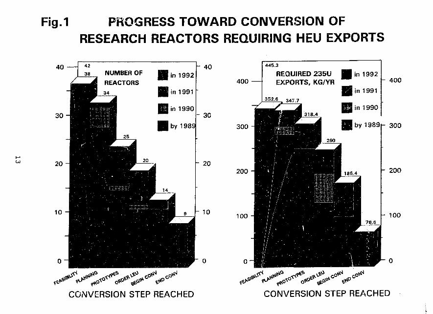
The forty-two operating reactors which required HEU exports when the RERTRProgram began can be subdivided in seven categories according to the most advanced stepwhich they have achieved. The two graphs of Fig. 1 illustrate the distributions of thenumbers of the reactors, and of the average number of kilograms of 23oU yearly exported foruse in their fuels, among the various categories. Both diagrams would be blank if noprogress toward reduction of HEU exports had been achieved, and fully shadowed if totalsuccess had been achieved and no further HEU exports were to be required. The percentagesof accomplished work are now 55.6% for the number of reactors and 57.7% for the yearly Uexports, while they were 54.9% and 54.8%, respectively, last year. The incrementalconversion progress recorded during the past year was not as remarkable as that recordedin 1991, but still points to an excellent overall conversion accomplishment. It must berecalled in this connection that, unless RERTR fuel development is resumed, four of thereactors considered in the diagrams cannot be converted: therefore, the highest fractionswhich are theoretically achievable are 90.5% and 79.2%.
Comparable progress has been attained a] so by the U.S. university reactors, which areconsidered separately because they do not require HEU exports. The University of Missouriat Rolla Reactor was successfully converted to LEU silicide fuel, bringing the total numberof U. S. converted reactors to six. Safety documentation was completed for one reactor andis nearly complete for five others. In addition, work was initiated for four TRIGA reactorsusing HEU fuel. The LEU conversion progress of the U. S. research reactors licensed by theU. S. Nuclear Regulatory Commission is discussed in Ref. 9.
PLANNED ACTIVITIES
The future activities which the RERTR Program plans to undertake are consistentwith the recent DOE guidance and with the plan outlined at last year's internationalmeeting. The major elements of this plan are described below.
1. Complete testing, analysis, and documentation of the fuels which have already beendeveloped, and support their implementation.
2. Transfer LEU fuel fabrication technology to countries and organizations which requiresuch assistance.
3. Perform calculations and evaluations for reactors planning to undergo conversion, toassist in improving performance and in resolving safety issues.
4. Within the available budget, develop a viable process, based on LEU, for theproduction of fission 99Mo in research reactors.
10
SUMMARY AND CONCLUSION
The disappearance of the Soviet Union and the end of the Cold War have broughtsignificant changes for the RERTR program. The new DOE Office of Arms Control andNonproliferation is now responsible for all DOE arms control and nonproliferation activities,and has assumed management of tbo RERTR program. Similarly, the RERTR program isnow an important component of the ANL Arms Control and Nonproliferation program. Theprogram would welcome the opportunity to cooperate with the CIS republics towards theelimination of the international traffic in Russian-supplied HEU.
»*The new emphasis on nonproliferation has caused renewed interest in the program's
accomplishments and goals. Congress came very close to funding resumption of fueldevelopment within the program, and asked for more information on the subject.
The Secretary of Energy announced that the reprocessing plants at Savannah Riverand at the Idaho National Engineering Laboratory will be shut down' in the near futpre. "TheRERTR program intends to cooperate to the fullest extent with reactor operators andpotential commercial reprocessors to ensure that a viable solution for reprocessing LEU fuelis found.
Consistent with DOE guidance and with a reduced but stable budget projection, theRERTR Program has concentrated its efforts on technology transfer and analytical assistancerelated to conversion utilizing already developed fuels. The conversion progress achieved todate corresponds to approximately 57% of what would be needed to convert all the reactorswhich used to import HEU from the West.
The RERTR Program intends to continue to participate in cooperative efforts tofacilitate and accelerate as much as possible the process of eliminating HEU frominternational commerce.
11
REFERENCES
1. Travelli, A., "Progress of the RERTR Program in 1990," Proceedings of the XIVInternational Meeting on Reduced Enrichment for Research and Test Reactors,Jakarta, Indonesia, 4-7 November 1991 (to be published).
!2. U.S, Nuclear Regulatory Commission: "Safety Evaluation Report Related to theEvaluation of Lo*.v-Enriched Uranium Silicide-Aluminum Dispersion Fuel for Use inNon-Power Reactors;" U.S. Nuclear Regulatory Commission Report NUREG-1313(July 1988).
3. Hofman, G. L., Rest, J., and Snelgrove, J. L., "A New Swelling Model and itsApplication to Aluminum Silicide Research Reactor Fuels," (these proceedings).
4. Woodruff, W. L., Been, J. R., and Costescu, C. I., "k Comparison of WIMS-D4MGenerated Cross-section Data with Monte Carlo," (these proceedings).
5. Bretscher, M. M., Snelgrove, J. L., and Ciocanescu, M., "Analytical Analysis of StartupMeasurements Associated with the First Use of LEU Fuel in Romania's 14-MWTRIGA Reactor," (these proceedings).
6. Toma, C, Barbos, D., Ciocanescu, M., Busuioc, P., Whittamore, W., and Snelgrove, J.L., "Measurement and Computations for Neutron Flux in TRIGA HEU Core with FourExperimental LEU Fuel Clusters," (these proceedings).
7. Deen, J. R., Snelgrove J. L., and Papastergiou, C, "Greek Research ReactorPerformance Characteristics after Addition of Beryllium Reflector and LEU Fuel,"(these proceedings).
8. Matos, J. E., "Analysis for Conversion of the Georgia Tech Research Reactor to LEUFuel," (these proceedings).
9. Michaels, T., "Status of HEU-LEU Conversions for Non-power Reactors Licensed bythe U.S. Nuclear Regulatory Commission," (these proceedings).
12
( j j
Fig.1 PROGRESS TOWARD CONVERSION OFRESEARCH REACTORS REQUIRING HEU EXPORTS
40NUMBER OF
REACTORS
- 40
- 30
- 20
10
400
445.3
REQUIREDEXPORTS,
352.6 347 -j
HHwjI^^Hi 318
235U 1KG/YR
|•
I.4
• in
Sin
iH inBW
1992
1991
1990
- 400
300
200 - 200
r 300
100 100
CG.WERSION STEP REACHED CONVERSION STEP REACHED
STATUS OF REDUCED ENRICHMENT PROGRAMSFOR RESEARCH REACTORS IN JAPAN
Keiji Kanda, Hideaki Nishihara
Research Reactor Institute, Kyoto UniversityKumatori-cho, Sennan-gun, Osaka 590-04, Japan
and
Yoshiaki Futamura, Eiji Shirai and Takumi Asauka
Japan Atomic Energy Research InstituteUchisaiwai-cho, Chiyoda-kii, Tokyo 100, Japan
ABSTRACT
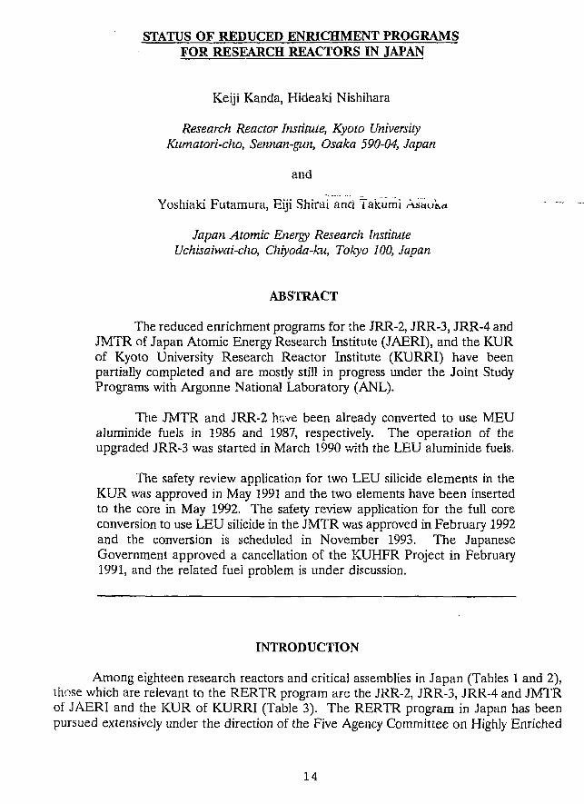
The reduced enrichment programs for the JRR-2, JRR-3, JRR-4 andJMTR of Japan Atomic Energy Research Institute (JAERI), and the KURof Kyoto University Research Reactor Institute (KURRI) have beenpartially completed and are mostly still in progress under the Joint StudyPrograms with Argonne National Laboratory (ANL).
The JMTR and JRR-2 have been already converted to use MEUaluminide fuels in 1986 and 1987, respectively. The operation of theupgraded JRR-3 was started in March 1990 with the LEU aluminide fuels.
The safety review application for two LEU silicide elements in theKUR was approved in May 1991 and the two elements have been insertedto the core in May 1992. The safety review application for the full coreconversion to use LEU silicide in the JMTR was approved in February 1992and the conversion is scheduled in November 1993. The JapaneseGovernment approved a cancellation of the KUHFR Project in February1991, and the related fuel problem is under discussion.
INTRODUCTION
Among eighteen research reactors and critical assemblies in Japan (Tables 1 and 2),those which are relevant to the RERTR program are the JRR-2, JRR-3, JRR-4 and JMTRof JAERI and the KUR of KURRI (Table 3). The RERTR program in Japan has beenpursued extensively under the direction of the Five Agency Committee on Highly Enriched
14
Uranium, which consists of the Science and Technology Agency, the Ministry of Education,Science and Culture, the Ministry of Foreign Affairs, JAERI and KURRI, which is heldevery three months. It has played a remarkable role in deciding policies related to theprogram, and the 62nd Committee was held on July 6, 1992, where Babcock & Wilcox wasauthorized as a fabricator of LEU silicide fuel for Japanese research reactors as well asCERCA. Recently, reprocessing of spent fuel has been mainly discussed.
The program in JAERI for the first step, in which the JRR-2 and JMTR were to beconverted to use 45% enriched uranium (MEU) aluminide fuels and the JRR-3 to use 20%enriched uranium (LEU) aluminide fuels, has been completed. The first criticality of thenew JRR-3 was achieved in March 1990. After that, the reactor power was increased step
-by step to high power level and the maximum power to 20 MW was established.
Further core conversion of the JMTR for use of LEU silicide fuel with burnableabsorber has been studied since 1984 in accordance with the Joint Study with ANL. Thesafety review application of the conversion was approved in February 1992, and theconversion is scheduled in November 1993. Studies on silicide fuel plate behavior underaccidental conditions are progressing by utilizing the NSRR. The JRR-2 has beenremodeled to realize the neutron field for the boron neutron capture therapy, and sevenpatients were treated since August 1990.
On the other hand, in KURRI the same efforts as in JAERI to reduce theenrichment of the KUR are in progress. The safety revisw application for two LEU silicideelements in the KUR was approved in May 1991 and the two elements have been insertedto the core in May 1992. The application of safety review of the full core conversion to useLEU silicide fuel will follow. Since February 1990, 21 patients were treated with the boronneutron capture therapy.
JAERI
JRR-2
The fuel of JRR-2 was converted from 93% high enriched uranium (HEU) to 45%medium enriched uranium (MEU) in 1987. JRR-2 has been subsequently operated for 39operation cycles (12 days / cycle) of more than 96,000 MWh.
After completion of the JRR-3 upgrading program, reactor utilization such as aneutron beam experiment gradually decreases in JRR-2. On the other hand5 Boron NeutronCapture Therapy (BNCT) has been actively done in this reactor, and seven patients havebeen successfully treated since August 1990. A trouble of the main cooling pump wasoccurred in July, 1991 and the repair works were followed for almost one year. The reactorhas been smoothly operated after the restart at the end of July 1992.
JRR-2 has been operated more than 30 years and its retirement might come nearfuture.
15
JRR-3M
The upgrading work for JRR-3 was started in August 1985 and the first criiicality ofthe new JRR-3 (JRR-3M) was achieved in March 1990, using LEU aluminum fuels (2.2gU/cc). The JRR-3M began to operate for capsule irradiation, beam experiments and soon at the reactor power of 20 MWt in November 1990. One operational cycle consists offour weeks for operation and one week for shut down work. No evidence of fuel failure hasbeen observed.
Neutron fluxes at beam experimental holes in JRR-3M are quite satisfactory and thecold neutron source has been also operated successfully.
The equilibrium core was attained in May 1991, and fourteen operation cycles havebeen subsequently achieved with the integral output of ~ 150,000 MWh as of beginning ofJuly 1992.
JRR-4
It is expected that the reactor operation with HEU fuels continues up to the middleof 1994, when almost all the HEU fuels will be consumed in JRR-4. Then, the conversionworks of the reactor core to LEU fuels might follow for about two years. JRR-4 is plannedto resume its operation in 1997.
The core design with LEU fuels is now under way. Seismic analyses of the reactorbuilding, accident analyses of fuel element and so on are carrying out for the safetyevaluation. The upgrade of utilization facilities is also under consideration.
JMTR
The conversion of the JMTR core from MEU fuel to LEU fuel is scheduled to bemade in November 1993. The LEU fuel for the JMTR is the silicide (U3Si2) fuel with4.8gU/cc, and burnable absorbers of cadmium wires are placed in each side plate. The useof the silicide fuel allows the JMTR to operate 26 consecutive days without refueling, whichis presently carried out after 12 days' operation. Operating characteristics of the JMTRremain unchanged.
For the safety analysis of the JMTR LEU core, many R&D works on silicide fuelhave been successfully conducted such as fission product release measurement, hydraulictests with dummy fuel elements and measurements of thermal conductivity. Inpileexperiments have been progressing in the NSRR to study the silicide fuel behavior underreactivity insertion accident condition.
The safety review was finished and the license on the use of the silicide fuel wasissued in February 1992. As a result of the safety analysis based on the latest knowledge,the emergency cooling system, the emergency power system and the safety protection systemwere decided to be partly upgraded. Approval on design and construction procedures ofthese upgradings by the Science and Technology Agency has been obtained, and theinstallation work is to be carried out in the next reactor overhaul period (from August toOctober of 1993).
16
KURRI
The Kyoto University Research Reactor (KUR, 5MW) has been operated since 1964using HEU fuel. The operation time has been shortened from 2,000 hr to 1,500 hr per yearsince 1993 to save uranium consumption. The existing HEU fuel can be used until March1995. In May 1995, the KUR is scheduled to convert to use LEU silicide fuel. The KURhas been still utilized for boron neutron capture therapy. Since February 1990, 21 patientsof cancer were treated by six chief medical doctors.
Prior to the full conversion, a demonstration to use two fuel elements (U3S12-AI, 3.2gU/cc) in the core had been planned. The safety review was completed and approved inMay 1991, and fuels were fabricated by CERCA in November 1992. After someimprovement e.g. to install a new CVCF electricity equipment to avoid a flow reverse ofprimary coolant, the two fuel elements have been inserted to the core in May 1992.
On the other hand, according to the suggestion of the government, the cancellationof the KUHFR (30MW) Project was applied to the government in December 1990 andapproved in February 1991. The handling of HEU received for the KUHFR is underdiscussion with the US Government.
R&D WORKS FOR LEU FUELS
Pulse Irradiation of Silicide Fuels in the NSRR
Inpile experiments are progressing in the NSRR to study the silicide fuel behaviorunder accidental conditions. Thermal and mechanical response, fuel failure initiation andfuel fragmentation are being investigated by subjecting the silicide test fuel plates to pulseirradiation.
So far, ten experiments have been conducted with mini-plate type, low enriched(19.89%) and high density (4.8g/cc) fresh silicice fuels cooled by stagnant water at roomtemperature and at atmospheric pressure in the test capsule. The energy deposited in thefuel ranged from 62 to 164 cal/g fuel and the maximum cladding temperature rises were200°C to 970°C depending on the energy depositions.
In this test period, fuel behavior at lower energy depositions has been studied indetails. It has newly observed that cracks on the solid cladding are formed, most probablyat quenching from film boiling, at around 100 cal/g fuel at which energy deposition claddingtemperature increases beyond the departure from nucleate boiling (DNB) condition but thepeak temperature is still much lower than the melting point of the cladding.
Development of High Uranium Density Fuels
Uranium silicides (U3Si2, U3Si) and U6Me (Me = Fe, Mn, Ni) have been examinedto clarify their irradiation performance and metallurgical behaviors with emphasis on the
17
latter because of higher uranium density.
Specimens were fabricated and subjected to the neutron irradiation in the JMTR.Post-irradiation examinations of the first capsule are now under way. Irradiation of thesecond capsule containing UsMe-type miniplates is in progress.
REFERENCES
1. K. Kanda, "Reducing Enrichment Program for Research Reactors in Japan", inProceedings of the International Meeting of Research and Test Core Conversion fromHEU to LEU Fuels, Argonne, USA, November 8-10, ANL/RERTR/TM-4CONF-821155, pp.24-32 (September 1983).
2. K. Sato, "Opening Statement to the International Meeting on Reduced Enrichmentfor Research and Test Reactors", in Proceedings of the International Meeting onReduced Enrichment for Research and Test Reactors, Tokai, Japan, October 24-27,1983, JAERI-M 84-073, pp.8-10 (May 1984).
3. K. Kanda, T. Shibata, I. Miyanaga, H. Sakurai and M. Kanbara, "Status of ReducedEnrichment Program for Research Reactor Fuels in Japan", in Proceedings ofInternational Meeting of Reduced Enrichment of Research and Test Reactors, Argonne,USA, October 15-18, 1984, ANL/RERTR/TM-6 CONF-8410173, pp.11-20 (July1985).
4. I. Miyanaga, K. Kamei, K. Kanda and T. Shibata, "Present Status of ReducedEnrichment Program for Research and Test Reactor Fuels in Japan", in ReducedEnrichment for Research and Test Reactors, Proceedings of an International Meeting,Petten, The Netherlands, October 14-16, 1985, D. Reidel Publishing Company,Dordrecht/Boston/Lancaster/Tokyo, pp.21-32 (March, 1986).
5. K. Kanda, T. Shibata, Y, Iso, H. Sakurai and Y. Okamoto, "Status of ReducedEnrichment Program for Research and Test Reactor Fuels in Japan", in Proceedingsof the 1986 International Meeting on Reduced Enrichment for Research and TestReactors, Gatlinburg, USA, November 3-6,1986, ANL/RERTR/TM-9 CONF-861185,pp.14-22.
6. Y. Futamura, H. Sakurai, Y. Iso, K. Kanda and I. Kimura, "Status of ReducedEnrichment Program for Research and Test Reactor Fuels in Japan", in Proceedingsof the 10th RERTR Meeting, Buenos Aires, Argentina, September 28- October 1,1987, in press.
7. K. Kanda, H. Nishihara, Y. Futamura, H. Sakurai and Y. Iso, "Status of ReducedEnrichment Program for Research Reactors in Japan", in Proceedings of the 11thRERTR Meeting, San Diego, USA, September 19-22, 1988, in press.
18
8. Y. Futamura, M. Kawasaki, Y. Iso, K. Kanda and M. Utsuro, "Status of ReducedEnrichment Program for Research and Test Reactor Fuels in Japan", in Proceedingsof the 12th RERTR Meeting, West Berlin, FGR, September 11-13, 1989, in press.
9. K. Kanda, H. Nishihara, Y. Futamura, M. Kawasaki and T. Asaoka, "Status ofReduced Enrichment Program for Research Reactors in Japan", in Proceedings of the13th RERTR Meeting, Newport, USA, September 23-27, 1990, in press.
10. Y. Futamura, M. Kawasaki, T. Asaoka, K. Kanda and H. Nishihara, "Status ofReduced Enrichment Program for Research Reactors in Japan", in Proceedings of the14th RERTR Meeting, Jakarta, Indonesia, November 4-7, 1991, in press.
19
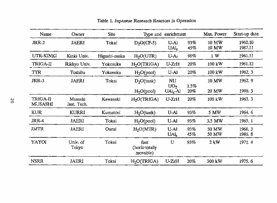
Table 1. Japanese Research Reactors in Operation
Name
JRR-2
UTR-KINKI
TRIGA-II
TTR
JRR-3
TRIGA-IIMUSASHI
KUR
JRR-4
JIvTTR
YAYOI
NSRR
Owner
JAERI
Kinki Univ.
Rikkyo Univ.
Toshiba
JAERI
MusashiInst. Tech.
KURRI
JAERI
JAERI
Univ. ofTokyo
JAERI
Site
Tokai
Higashi-osaka
Yokosuka
Yokosuka
Tokai
Kawasaki
Kumatori
Tokai
Oarai
Tokai
Tokai
Type and
D2O(CP-5)
H2O(UTR)
H2O(TRIGA)
H2O(pool)
D2O(tank)
H2O(pool)
H2O(TRIGA)
H2O(tank)
H20(pool)
H2O(MTR)
fast(horizontally
movable)
H2O(TRIGA)
enrichment
U-AlUA1X
U-Ai
U-ZrH
U-Al
NU
uo2UA1X-A1
U-ZrH
U-Al
U-Al
U-AlUA1X
U
U-ZrH
93%45%
90%
20%
20%
1.5%20%
20%
93%
93%
93%45%
93%
20%
Max. Power
10 MW10 MW
1 W
100 kW
100 kW
10 MW
20 MW
100 kW
5 M W
3.5 MW
50 MW50 MW
2 k W
300 kW
Start-up date
1960.101987.11
1961.11
1961.12
1962. 3
1962. 9
1990. 3
1963. 3
1964. 6
1965. 1
1968. 31985. 8
1971. 4
1975. 6
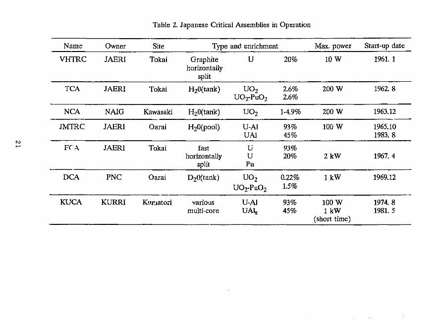
Table 2. Japanese Critical Assemblies in Operation
Name
VHTRC
TCA
NCA
JMTRC
FCA
DCA
KUCA
Owner
JAERI
JAERI
NAIG
JAERI
JAERI
PNC
KURRI
Site
Tokai
Tokai
Kawasaki
Oarai
Tokai
Oarai
Kiimatori
Type
Graphitehorizontally
split
H20(tank)
H20(tank)
H20(pool)
fasthorizontally
split
D20(tank)
variousmulti-core
and enrichment
U
UO2UO2-PuO2
UO2
U-AlUA1
UUPu
uo2UO 2 -PuO 2
U-AlUA1X
20%
2.6%2.6%
1-4.9%
93%45%
93%20%
0.22%1.5%
93%45%
Max. power
10 W
200 W
200 W
100 W
2kW
lkW
100 Wl k W
(short time)
Start-up date
1961. 1
1962. 8
1963.12
1965.101983. 8
1967. 4
1969.12
1974. 81981. 5
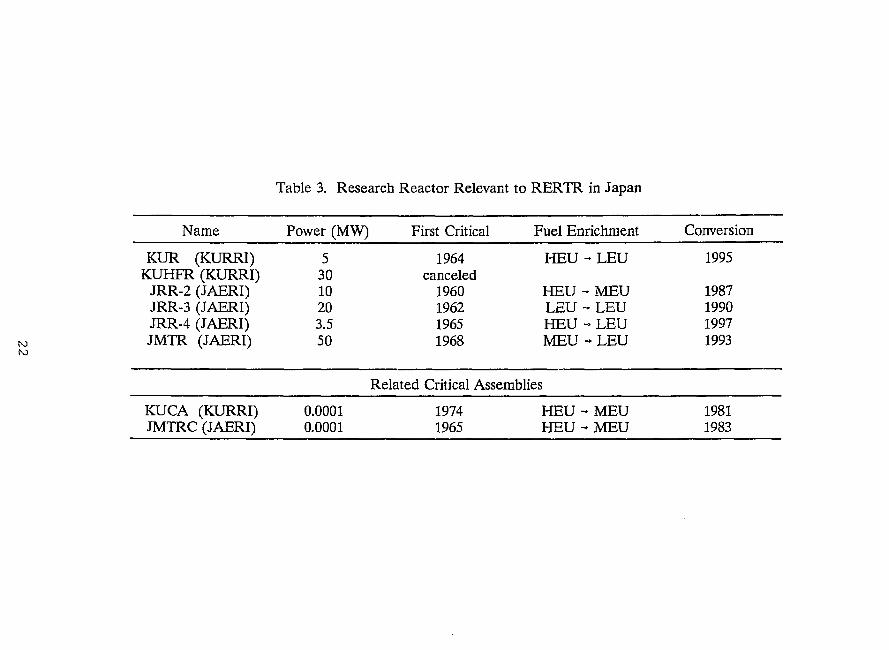
Table 3. Research Reactor Relevant to RERTR in Japan
ro
Name Power (MW) First Critical Fuel Enrichment
Related Critical Assemblies
KUCA (KURRI) 0.0001JMTRC (JAERI) 0.0001
19741965
HEU - MEUHEU-MEU
Conversion
KUR (KURRI)KUHFR (KURRI)
JRR-2 (JAERI)JRR-3 (JAERI)JRR-4 (JAERI)JMTR (JAERI)
53010203.550
1964canceled
1960196219651968
HEU
HEULEUHEUMEU
- L E U
- M E U- L E U- L E U- L E U
1995
1987199019971993
19811983
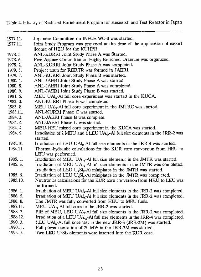
Table 4. Hib- ~.ry of Reduced Enrichment Program for Research and Test Reactor in Japan
1977.11. Japanese Committee on INFCE WC-8 was started.1977,11. Joint Study Program was proposed at the time of the application of export
license of HEU for the KUHFR.1978. 5. ANL-KURRI Joint Study Phase A was Started.1978. 6. Five Agency Committee on Highly Enriched Uranium was organized.1978. 2. ANL-KURRI Joint Study Phase A was completed.1979. 5. Project team for RERTR was formed in JAERI.1979. 7. ANL-KURRI Joint Study Phase B was started.1980. 1. ANL-JAERI Joint Study Phase A was started.1980. 8. ANL-JAERI Joint Study Phase A was completed.1980. 9. ANL-JAERI Joint Study Phase B was started.1981. 5. MEU UA1X-A1 full core experiment was started in the KUCA.1983. 3. ANL-KURRI Phase B was completed.1983. 8. MEU UA1X-A1 full core experiment in the JMTRC was started.1983.11. ANL-KURRI Phase C was started.1984. 3. ANL-JAERI Phase B was complete.1984. 4. ANL-JAERI Phase C was started.1984. 4. MEU-HEU mixed core experiment in the KUCA was started.1984. 9. Irradiation of 2 MEU and 1 LEU UA1X-A1 full size elements in the JRR-2 was
started.1984.10. Irradiation of LEU UA1X-A1 full size elements in the JRR-4 was started.1984.11. Thermal-hydraulic calculations for the KUR core conversion from HEU to
LEU was performed.1985. 1. Irradiation of MEU UA1X-A1 full size elemen s in the JMTR was started.1985. 3. Irradiation of MEU UA1X-A1 full size elements in the JMTR was completed.
Irradiation of LEU UxSiy-Al miniplates in the JMTR was started.1985. 6. Irradiation of LEU UxSiy-Al miniplates in the JMTR was completed.1985.10. Neutronics calculations for the KUR core conversion from HEU to LEU was
performed.1986. 1. Irradiation of MEU UA1X-A1 full size elements in the JRR-2 was completed1986. 5. Irradiation of MEU UA1X-A1 full size elements in the JRR-2 was completed.1986. 8. The JMTR was fully converted from HEU to MEU fuels.1987.11. MEU UA1X-A1 full core in the JRR-2 was started.1988. 7. PIE of MEU, LEU UA1X-A1 full size elements in the JRR-2 was completed.1988.12. Irradiation of a LEU UAL-A1 full size elements in the JRR-4 was completed.1990. 3. LEU UA1X-A1 full core test in the new JRR-3 (JRR-3M) was started.1990.11. Full power operation of 20 MW in the JRR-3M was started.1992. 5. Two LEU U3S12 elements were inserted into the KUR core.
23
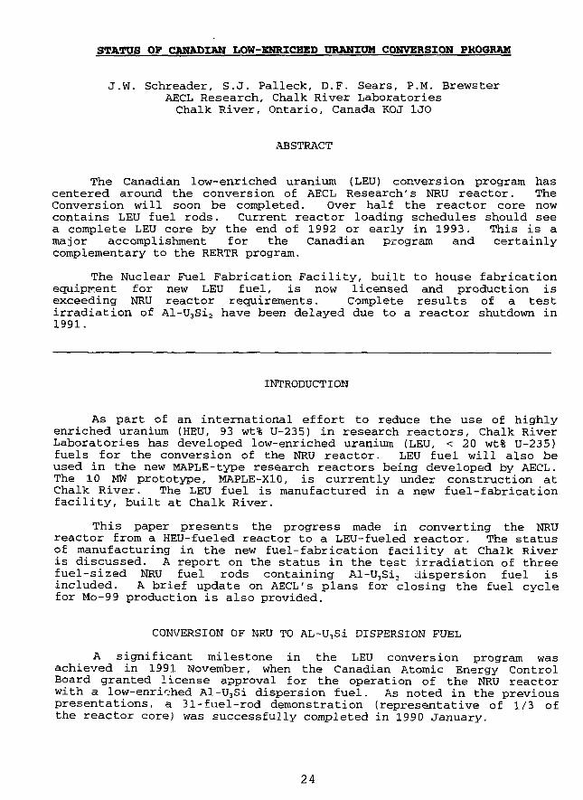
STATUS OF CANADIAN LOW-ENRICHED URANIUM CONVERSION PROGRAM
J.W. Schreader, S.J. Palleck, D.F. Sears, P.M. BrewsterAECL Research, Chalk River LaboratoriesChalk River, Ontario, Canada KOJ 1J0
x^BSTRACT
The Canadian low-enriched uranium (LEU) conversion program hascentered around the conversion of AECL Research's NRU reactor. TheConversion will soon be completed. Over half the reactor core nowcontains LEU fuel rods. Current reactor loading schedules should seea complete LEU core by the end of 1992 or early in 1993. This is amajor accomplishment for the Canadian program and certainlycomplementary to the RERTR program.
The Nuclear Fuel Fabrication Facility, built to house fabricationequipment for new LEU fuel, is now licensed and production isexceeding NRU reactor requirements. Complete results of a testirradiation of Al-U3Si2 have been delayed due to a reactor shutdown in1991.
INTRODUCTION
As part of an international effort to reduce the use of highlyenriched uranium (HEU, 93 wt% U-235) in research reactors, Chalk RiverLaboratories has developed low-enriched uranium (LEU, < 20 wt% U-235)fuels for the conversion of the NRU reactor. LEU fuel will also beused in the new MAPLE-type research reactors being developed by AECL.The 10 MW prototype, MAPLE-X10, is currently under construction atChalk River. The LEU fuel is manufactured in a new fuel-fabricationfacility, built at Chalk River.
This paper presents the progress made in converting the NRUreactor from a HEU-fueled reactor to a LEU-fueled reactor. The statusof manufacturing in the new fuel-fabrication facility at Chalk Riveris discussed. A report on the status in the test irradiation of threefuel-sized NRU fuel rods containing Al-U3Si2 dispersion fuel isincluded. A brief update on AECL's plans for closing the fuel cyclefor Mo-99 production is also provided.
CONVERSION OF NRU TO AL-U3Si DISPERSION FUEL
A significant milestone in the LEU conversion program wasachieved in 1991 November, when the Canadian Atomic Energy ControlBoard granted license approval for the operation of the NRU reactorwith a low-enriched Al-U3Si dispersion fuel. As noted in the previouspresentations, a 31-fuel-rod demonstration (representative of 1/3 ofthe reactor core) was successfully completed in 1990 January.
24

In 1992 January, the first LEU rods of the full-scale conv -sioneffort were inserted into the reactor. For the first four months,reactor loadings were both HEU and LEU rods. Since that time, onlyLEU fuel has been loaded into the reactor, and at the end of 1992August the core consisted of 40 HEU rods and 50 LEU rods. At thecurrent loading schedule, by year end or early in 1993, the entire NRUcore will be made up of LEU fuel. This will complete the conversionof the NRU reactor from a HEU (93 wt% U-235) -fuelled reactor to aLEU-reactor (19.75 wt% U-235).
With over half the reactor conversion complete, there is nothingto indicate that this target will not be met. This will mark theculmination of a tremendous effort, which has seen AECL not onlydevelop a new fuel, but also new fabrication processes and facilitatesto fabricate the fuel. It has also led to the development of the LEU-fuelled MAPLE-X reactor. Assuming the conversion of NRU reactorremains trouble-free, fuel wise, the need for HEU to fuel this reactorwill no longer exist. For the RERTR program, this effectively reducesthe export of HEU from the USA by 66.4 kg/a and is a milestone for theprogram.
NRU-EXPERIENCE WITH LEU DRIVER FUEL RODS
From the reactor operations point of view, there are a fewdifferences between the HEU and LEU driver fuel rods.
The U-235 content of both rod types is specified to be the same,0.49 kg. The shape and size of the 12 elements are indistinguishable.The basic difference between the rods is that the LEU 'meat' contains0.3 kg less aluminum, 0.1 kg more silicon, and 2.0 kg more U-238 thanthe HEU 'meat.'
The additional mass of the rod assemblies does not affect theusual fuel handling.
The additional U-238 is a reactivity load; howevor, the effect ispartially offset by the reactivity gain due to the production ofplutonium. From the fuel management point of view, the two rod typesare equivalent, except for the extra plutonium in spent LEU rods. Agreater energy output [MWd] is required from the LEU rods to keep thefissile content of spent rods below 13 0 g. This limit is imposed tominimize the cost of interim storage of spent rods.
To achieve this greater burnup, the core loading of the reactoris being modified as more and more sites contain LEU rods. Twoactions can increase the exit burnup: Providing additional fueJ. rodsites or removing a neutron absorber. To increase the number of fuelrod sites, a peripheral moderator site may be converted to a site foran old fuel rod. To reduce neutron absorption, and isotope productionrod, such as an alumina nitride rod for the production of Carbon-14from Nitrogen-14, may be removed from the core and used as a moderatorsite or as an additional fuel-rod site. Since NRU is a large reactorwith a lattice of 227 positions, there are many options forrearranging the core.
25
The effects of converting the core from HEU to LEU driver fuelrods were surveyed in 1984. This predicted that the exit burnup wouldbe reduced by 5% is five additic-^1 fuel-rod sites were used withoutchanging the number of absorber rods. Although it is really too earlyto either confirm or deny our predictions, it appears the impact onour core loading will be smaller than predicted.
NUCLEAR FUEL FABRICATION UPDATE - LEU PRODUCTION
Since the last update was given in 1990, the LEU Nuclear FuelFabrication Facility (NFFF) at Chalk River has achieved one of itsmajor goals in developing the fabrication process. It has beenlicensed to operate with no limitation on quantities processed withinthe maximum amounts allowed criticality approval. Prior to this, thefacility was licensed to process only a fixed small quantity of fuelat a time.
The major challenge is realizing the full capability of theproduction equipment has not been technological, but to learn what ittakes to comply to modern regulatory requirements.
The NFFF has been operating since 1990 June, fabricating LEU fuelfor the NRU research reactor. Conditions in licensing permitted onlysmall quantities of fuel processing, until satisfactory training andquality programs could be demonstrated. While developing theseprograms, the regulatory requirements changed. By the time anacceptable quality program was developed, what was initiallyacceptable as a training program was no longer valid: The regulatorsin Canada were indeed raising their standards and the NFFF, as a newfacility, prov-Lied an opportunity for them to set an example for otherupcoming projects.
The NFFF is currently in a position to fully meet all productionrequirements. Customers in 1993 include NRU operating full time, NRXpart-time, first charge and replacement charge fuel for MAPLE-X10 atChalk River, first charge and replacement charge fuel for SouthKorea's MAPLE research reactor, and supporting the isotope productionbusiness. We have also acquired new electron beam welding equipmentfor welding fuel elements and flow tubes, and real-time X-ray forimproved fuel inspection.
The LEU fuel presently being produced is based on Al-U3Si.However, a new glovebox line has been designed for Al-U3Si2-based LEUfuel. From a fuel-fabrication perspective, our interest in changingto U3Si2 is improved efficiency to the fuel fabrication process. Oncethe results of the test irradiations of the three full-size Al-U3Si2fuel rods are known, and assuming they are positive, we will proceedwith the procurement and set-up of this new line. Some changes to ouroperating license will be required, but these will likely be minimal.
26
AL-U3Si2 FUEL DEVELOPMENT AND IRRADIATION TESTING
As reported previously, Al-U3Si2 fuel-fabrication technology hasbeen developed at Chalk River to complement our Al-U3Si capability.The irradiation of 12 mini-elements containing Al-64 wt% U3Si2 wascompleted successfully in 1989 December, and the results were sharedat the RERTR Conferences in both Newport and Jakarta.
A demonstration irradiation of three prototype full-length Al-U3Si2 fuel rods has just been completed. The three fuel-rod lengthrods were inserted in NRU in 1990 August. However, with the shutdownof NRU for most of 1991, completion of the full test-irradiation wasdelayed until this year. The three test fuel rods were removed fromthe reactor during the first week of 1992 September. We havecompleted visual examinations of the high-burnup rods and the elementsappear t'j be in excellent condition. However, there has beeninsufficient time for detailed post-irradiation examination.Therefore, we are not able to report the final results of irradiationat this meeting, but do look forward to sharing those results at thenext RERTR meeting.
TARGETS FOR ISOTOPE PRODUCTION
One of the long-term objectives of the radioisotopes operation atChalk River has been to close the fuel cycle for Mo-9 9 production.The needed steps include recovering the enriched uranium inventoryfrom previous Mo-99 target dissolution, recycling the material, andfurther depleting it. The program, of course, will have to satisfyboth environmental and safeguards criteria and regulations.
Consequently, preliminary studies on recovering the uranium fromMo-99 target dissolutions are continuing. In parallel, a project onthe development and qualification of a new target, based on recoveredenriched uranium (REU) , as well as LEU, is underway. Both metal andoxide target designs are being pursued at present. We anticipateirradiation testing is approximately 1-2 years away.
CONCLUSIONS
1. The LEU fuel-fabrication facility at Chalk River has overcomethe major obstacle to full-capacity production. Programs have beendeveloped to satisfy modern regulatory requirements, and the facilityis well positioned to achieve full efficiency and maintain the highstandards of quality and safety experienced at Chalk River.
The NFFF is also fully capable of meeting all its customers'demands while considering opportunities for new commercial fuelcontracts, as well as commercial electron beam welding and thespecialized applications for real-time X-ray inspections.
2 . The conversion of the NRU reactor from HEU to LEU will soonbe completed. From the reactor operators' point of view, theconversion to date has been uneventful. Fuel failures have notoccurred and no fission-product contamination has been detected in thecoolant.
27
3. Assuming that the cm rent fueling schedule of NRU with LEUfuel rods remains trr^itie-free, NRU's conversion to LEU will becomplete by thp iad of 1992 or early in 1993. This effectivelyreduces the quantity of HEU exported from the USA by 66.4 kg/a. Thisis a major achievement for Canada and the RERTR program.
REFERENCES
1. Sears, D.F.: "Development and Irradiation Testing of Al-U3Si2Fuel at Chalk River Laboratories," Proceedings of the InternationalRERTR Meeting, Jakarta, Indonesia, 1991 November 4-7 (to bepublished).
2. Sears, D.F.: "Status of LEU Fuel Development and Testing atCRNL, " Proceedings of the International RERTR Meeting, Newport, RhodeIsland, USA, 1990 September 23-27 (to be published).
3. Sears, D.F.: "Status of LEU Fuel Development and Conversionof NRU, " Proceedings of the International RERTR Meeting, West Berlin,FRG, 1989 September 10-14, Published 1991.
4. Schreader, J.W., Kennedy, I.C., and Sears, D.F.: "Status ofCanadian Low-Enriched Uranium Conversion Program," Proceedings ofInternational RERTR Meeting, San Diego, USA, 1988 September 19-22 (tobe published).
28
S E S S I O N II
September 28, 1992
FUEL DEVELOPMENT AND FABRICATION
Chairman:
A. Travelli(Argonne National Laboratory, USA)
29
OPTIMIZATION OF SILICIDE FUEL ELEMENTS
A. BALLAGNY - J-P, BEYLOT - J. PAILLERECEA SACLAY
91191 GIF-SUR-YVETTE CEDEX, FRANCE
J-P. DURAND - Y. FANJAS - A. TISSIERCERCA ROMANS
BP 111426104 ROMANS-SUR-ISERE, FRANCE
ABSTRACT
The purpose of this paper is to show that it ispossible to increase the U-235 loading per fuel elementwithout exceeding the universally qualified maximumuranium density of 4.8 g/cm3 or modifying the fuelelement geometry. The corresponding R & D work includesboth safety aspects and industrial productionrequirements.
INTRODUCTION
Most of the reactor operators who have decided to usesilicide fuels for core conversion have chosen the U3Si2 fuel,with a maximum density of 4.8 g/cm3.This choice stems from the need of the best balance between thefollowing requirements :
- high U-235 loading- easy fuel manufacturing technique- good behaviour under irradiation.
All qualification programs have been concentrated on thisproduct.However, in the past two years, the picture has been profoundlymodified.Although the reactor operators had been implicitly led to theconviction that the DOE would be willing to reprocess this typeof fuel, to day it is no longer the case.
31
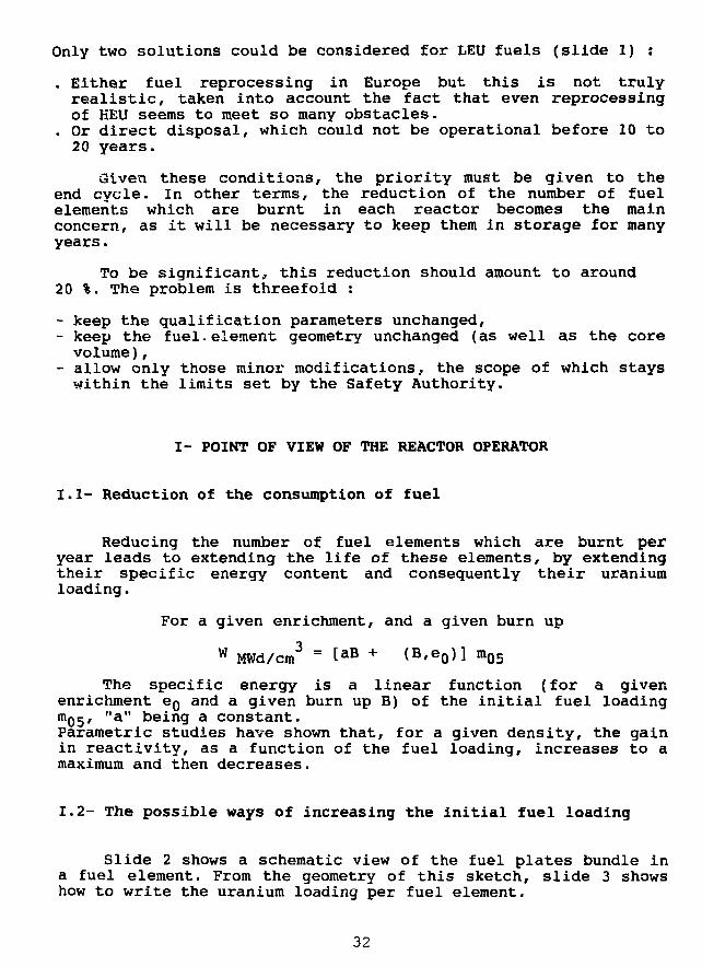
Only two solutions could be considered for LEU fuels (slide 1) :
. Either fuel reprocessing in Europe but this is not trulyrealistic, taken into account the fact that even reprocessingof HEU seems to meet so many obstacles.
. Or direct disposal, which could not be operational before 10 to20 years.
these conditions, the priority must be given to theend cycle. In other terms, the reduction of the number of fuelelements which are burnt in each reactor becomes the mainconcern, as it will be necessary to keep them in storage for manyyears.
To be significant, this reduction should amount to around20 %. The problem is threefold :
- keep the qualification parameters unchanged,- keep the fuel, element geometry unchanged (as well as the corevolume),
- allow only those minor modifications, the scope of which stayswithin the limits set by the Safety Authority.
I- POINT OF VIEW OF THE REACTOR OPERATOR
1.1- Reduction of the consumption of fuel
Reducing the number of fuel elements which are burnt peryear leads to extending the life of these elements, by extendingtheir specific energy content and consequently their uraniumloading.
For a given enrichment, and a given burn up
w MWd/cm3 = taB + (B'e0>] m05
The specific energy is a linear function (for a givenenrichment eg and a given burn up B) of the initial fuel loadingm05' "a" Dein9 a constant.Parametric studies have shown that, for a given density, the gainin reactivity, as a function of the fuel loading, increases to amaximum and then decreases.
1.2- The possible ways of increasing the initial fuel loading
Slide 2 shows a schematic view of the fuel plates bundle ina fuel element. From the geometry of this sketch, slide 3 showshow to write the uranium loading per fuel element.
32
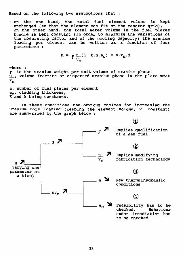
Based on the following two assumptions that :
- on the one hand, the total fuel element volume is keptunchanged (so that the element can fit on the reactor grid),
- on the other hand, the total water volume in the fuel platesbundle is kept constant (in order to minimize the variations ofthe moderating factor and of the cooling capacity) the uraniumloading per element can be written as a function of fourparameters :
M = p u_(K -k.n.ec) = n.v_.d
'mwhere :f is the uranium weight per unit volume of uranium p>*aseu , volume fraction of dispersed uranium phase in the plate meatvm
n, number of fuel plates per elementec, cladding thickness,K and k being constants.
In these conditions the obvious choices for increasing theuranium core loading (keeping the element volume, V, constant)are summarized by the graph below :
M(varying oneparameter at
a time)
nv,m
a 7* Implies qualification' of a new fuel
u 7* Implies modifyingv m fabrication technology
n jl New thermalhydraulicconditions
Feasibility has to bechecked. Behaviourunder irradiation hasto be checked
33
1.2.1- Discussion
- Branch
- Branch
- Branch
- Branch
Increase of p : involves developing a denserqualified compound. So far the U3Six fuel has beensuccessfully tested.However, the qualification of this type of fuelcould take some time.It is the subject of various studies which willnot be discussed here.
Increasing the ratio :
volume of uranium dispersed phasevolume of meat
means going beyond the present fabrication limitsin order to be able to produce U3Si2-Al platesloaded at more than 5 g/cm .
The decrease of the number of plates leads to asmaller overall exchange surface area and to adifferent element pressure drop. This choice wouldimply changing the thermalhydraulic conditions ofthe core.
The diminution of the cladding thickness allows anincrease of the meat volume without modifying thenumber of plates or their overall thickness. Thissolution seems interesting, provided manufacturingdifficulties can be tackled.
1.2.2- Limitations and prospects
A A e cia(j reduction in the cladding thickness leads to a meatthickness increase 2 A e ciacj, if the overall plate thickness iskept constant.
A reasonable compromise could be to reduce the claddingthickness from 0.38 mm to 0.34 mm (about 10 % reduction) leadingto a core thickness increase from 0.51 mm to 0.59 mm (about 15 %increase) corresponding - at constant density - to a 15 % coreloading increase ( to achieve the same uranium loading increase,without modifying the cladding thickness, would require toincrease the density from 4.8 g/cm3 to 4.8 g/cm3 x 0.59 = 5.55g/cmJ) 0.51
For the OSIRIS reactor,this 15 % uranium loading increasewould correspond to the burning of 60 elements per year insteadof 70 per year.
34
Cladding thickness of current fabrications is 0.38 mm withlocal absolute minimum fixed at 0.25 mm.Assuming the local meat thickness variations are independant fromthe average cladding thickness, the reduction of the averagecladding from 0.38 to 0.34 mm requires a corresponding reductionof the local minimum cladding. The allowable cladding reductionas well as the acceptable surface defects depth will bedetermined by irradiation experiments,
II- SAFETY ANALYSIS
From the above considerations it follows that thequalification of fuel elements with increased core thickness willrely essentially upon the behaviour under irradiation.Consequently a dedicated program has been sat up, the purpose ofwhich is to irradiate full size plates with local minimumcladding thickness reaching 0*2 mm.The experimental irradiation will take place in the SILOEreactor.
Description of the IRIS irradiation test device (slide 4)
IRIS "Installation d'Irradiation et du Suivi d'epaisseur" isthe experiment set up at the reactor SILOE in GRENOBLE for theabove purpose.
It consists of an irradiation box located at the peripheryof the reactor core, with a capacity for 8 full size plates.Four of them are inert and have an overall thickness of 1.27 mmand the other four ones are fuel plates with the same overallthickness, the former ones insuring the correct waterdistribution.
The fuel plates are removable. At the end of each fuelcycle, they are taken out of the irradiation box and placed on aspecially designed measuring bench.
Swelling under irradiation is monitored along 5 verticaltracks. Thickness variations are automatically recorded(slide 5).
35
Ill- POINT OF VIEW OF THE FUEL MANUFACTURER
III.l- Technical aspects
Slide 6 shows the comparison between the present OSIRIS fuelplate and the new plate type considered above.The present OSIRIS plate corresponds to the standard silicideplate : classical dimensions for the cladding (0.38 mm), the meat(0.51 mml and the plate (1.27 mm) and standard uranium density of4.8 g/cm3 with the U3S12 dispersion fuel.
With respect to this classical plate (later referred to asstandard plate in this paper), the new type (later referred to asthick core plate) is characterized by the followingmodifications:
- a 10 % decrease in the average cladding thickness- a 20 % decrease in the cladding local minimum- and a 15 % increase in the meat thickness.
Other characteristics such as overall plate thickness anduranium density remain unchanged.
Above modifications may give rise to some consequences onthe manufacturing and the quality of fuel plates. As far asmanufacturing is concerned, the manufacturer has to check therolling behaviour of the product. As far as quality is concerned,one must make sure that the specified criteria can be reliablymet on large scale production. Practically, the followingcriteria are of concern :
- the local minimum cladding in the current part of the meat, andin the dog-bone area.
- the maximum permissible surface defect depth which will be allthe smaller as the absolute minimum cladding will be reduced.
- besides, the increased meat thickness influence on the uraniumdistribution homogeneity in the fuel plate has to be checked.
111.2- Preliminary tests
In order to check the technical feasibility of plates withtaicker meat and reduced cladding, 16 full size depleted fuelplates were t. produced. Due to the previously explainedparticularities of the product, the fabrication parameters wereadjusted and the necessary manufacturing precautions taken.For purpose of comparison, standax'd plates were simultaneouslyproduced as a reference.The test results are described herebelow.
36
III.2.1- Cladding and meat thicknesses
5 of the 16 thick core and 1 of the 6 standard plates werecut for micrographic inspection. Two sections were made in thedog-bone area (one at each core end) and one in the current partof the meat.
The corresponding results are summarized in slide 7.The range of results obtained for the plates is reported in thecolumn "measurements result".For each variable, the measured data stand within a narrow range,which is an indication of the good reproducibility of results.
For both types of plates, the average cladding and meatthicknesses comply with the expected values : respectively 0.38and 0.34-0.35 mm for the cladding, 0.51 and 0.58-0.59 mm for themeat.
In any case, the minimum cladding remains significantlyabove the specification. With respect to the standard plate, itis decreased by 0.04-0.05 mm which is consistent with the averagecladding thickness reduction.Examination of the micrographic pictures (slide 8) does notindicate noticeable differences between the two types of plates.Both present a normal morphology . nd a sound interface betweenmeat and cladding.
III.2.2- Uranium distribution homogeneity
Specially designed X-ray scanning machines are used tocontrol quantitatively the homogeneity of uranium distribution infuel plates. A focused X-ray beam goes through the plate. Bymeasuring the absorption of the beam across the plate, theuranium density variations are determined.The whole plate surface is inspected by successive scans alongits core length. Slide 9 shows a representative record along onescanning line of each plate type.As can be seen on the slide, both records look alike. In eachcase the uranium distribution easily stands within the specifiedlimits. The similar aspects of the profiles indicate that thechange in meat thickness does not significantly modify the fuelcore homogeneity.
Ill.3- Influence on the fabrication yield
The preliminary tests show the feasibility of reducedcladding fuel plates. All the manufactured plates havesuccessfully passed the usual inspections and the dispersion ofcorresponding results is small.
37
Nevertheless, as for any new product and in particular inthis case since we stand outside the standard manufacturingconditions, large scale reproducibility tests must be carried outto make sure that the fabrication yield remains high enough sothat economic conditions can be achieved.In this respect, the maximum allowable surface defect depth is ofspecial importance due to the reduced cladding thickness : itwill be determined by the test under irradiation of platesbearing calibrated grooves machined on their surfaces.
IV- IRRADIATION TEST PROGRAM
IV.1- Irradiation testing
Although the fuel meat in pile behaviour does not need to beproven anymore, it is necessary to irradiate test plates to checkthe reduced cladding resistance to corrosion and fission productsrelease. In particular, the cladding thickness absolute minimum/which results from a combination of local meat thicknessvariations and surface defects, will be decided from the testresults. Therefore, the following three-phase irradiation programhas been set up :- Irradiation of 4 full size plates in the SILOE reactor usingthe IRIS device : one standard (for purpose of comparison) and 3thick core plates will be irradiated. One of the three thick coreplates will present a defectless surface. The other two will bearcalibrated machined defects which will locally reduce thecladding thickness to less than 0.2 mm.
- Fission product release :As part of a more general program to study the fission productrelease of silicide fuels, thick core mini plates will betested to compare their behaviour with standard mini plates.These tests will be carried out in an irradiation loop of theSILOE reactor.
- Prototype elements irradiation :The third phase corresponds to the official in pilequalification of fuel elements made with thick core plates. Forthis purpose two prototype elements will be irradiated in theOSIRIS reactor.
38
IV.2- Irradiation program schedule (slide 10)
The optimization phase consisting of design calculations andfabrication feasibility has been completed as previouslypresented. Irradiation testing is under preparation. The 4 platesto be tested in SILOE are under fabrication at CERCA.Their irradiation will take place in 1993. As far as the fissionproduct release experiment is concerned, the test plates will bemanufactured in 1993 and irradiated in 1993-1994. The two OSIRISprototype elements will be produced in 1993 for irradiation inthe OSIRIS reactor in 1994.
CONCLUSION
The concept of thicker meat and constant plate thicknessallows to increase significantly the uranium loading per fuelelement without changing the type of fuel, the fuel density orthe thermalhydraulic conditions. Therefore it is a valuable andrelatively easy way to extend the fuel element core lifetime.The preliminary manufacturing tests demonstrated the feasibilityof the thick core plates. A specific program aiming at qualifyingthem under irradiation is underway which will be completed by theend of 1994.
39
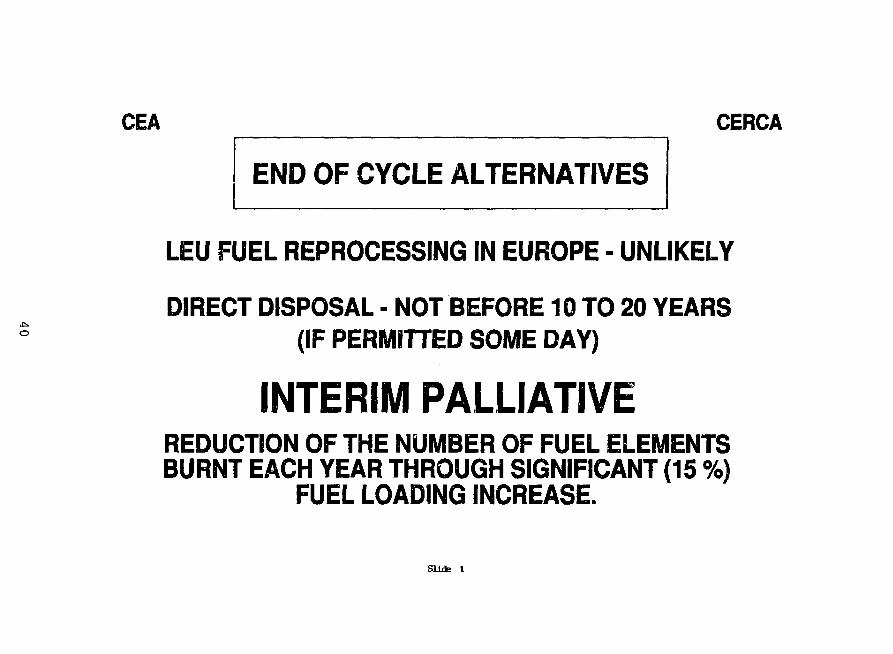
CEA CERCA
END OF CYCLE ALTERNATIVES
o
LEU FUEL REPROCESSING IN EUROPE - UNLIKELY
DIRECT DISPOSAL - NOT BEFORE 10 TO 20 YEARS(IF PERMITTED SOME DAY)
INTERIM PALLIATIVEREDUCTION OF THE NUMBER OF FUEL ELEMENTSBURNT EACH YEAR THROUGH SIGNIFICANT (15 %)
FUEL LOADING INCREASE.
Slide 1
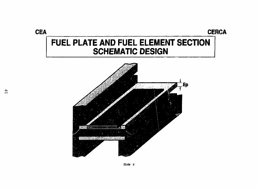
CEA CERCA
FUEL PLATE AND FUEL ELEMENT SECTIONSCHEMATIC DESIGN
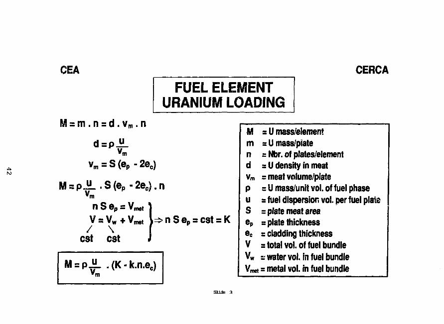
CEA CERCA
FUEL ELEMENTURANIUM LOADING
= m .n = d . v m . n
vm = S (ep »2ec)
= P " .S(ep-2e c) .nv,m
n S ep =
cst
"Pvm"
\w
cst
• ( K -
i
k.n.e
nS eP = cst = K
K H * 3
MmndVm
PuSer,ec
VVwV ^
= U mass/elementr U mass/piate= Nbr. of plates/element= U density in meats meat volume/plate= U mass/unit vol. of fuel phase=fuel dispersion vol. per fuel plate= plate meat area= plate thickness= cladding thickness=total vol. of fuel bundles water vol. in fuel bundle
t = metal vol. in fuel bundle
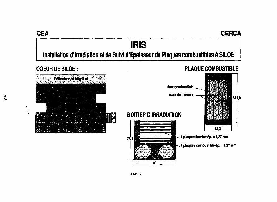
00
CEA CERCA
IRISInstallation d'lrradiation et de Suivi d'Epaisseur de Plaques combustibles a SILOE
COEUR DE SILOE: PLAQUE COMBUSTIBLE
ame combustible
axesdemesure641,9
BOITIER D'IRRADIATION
4 plaques Inertes e> = 1,27 nm
4 plaques combustible ep. = 1,27 mm
Slide 4
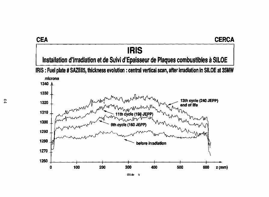
CEA CERCA
IRISInstallation d'Irradiation et de Suivi d'Epaisseur de Plaques combustibles a SILOE
IRIS: Fuel plate # SAZE05, thickness evolution: central vertical scan, after irradiation in SILOE at 35MWmicrons
1340 1
13th cycle (240 JEPP)
1260
600 z (mm)
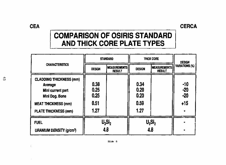
CEA CERCA
COMPARISON OF OSIRIS STANDARDAND THICK CORE PLATE TYPES
CHARACTERISTICS
CLADDING THICKNESS (mm)AverageMini current partMini Dog. Bone
MEAT THICKNESS (mm)
PLATE THICKNESS (mm)
FUEL
URANIUM DENSITY (g/cm3)
STANDARD
DESIGN
0.380.250.250.511.27
MEASUREMENTSRESULT
U3Si24.8
•HICK CORE
DESIGN
0.340.200.200.591.27
MEASUREMENTSRESULT
U3Si2
4.8
DESIGNVARIATIONS (%)
-10-20-20+15
m
B
Sliifc 6
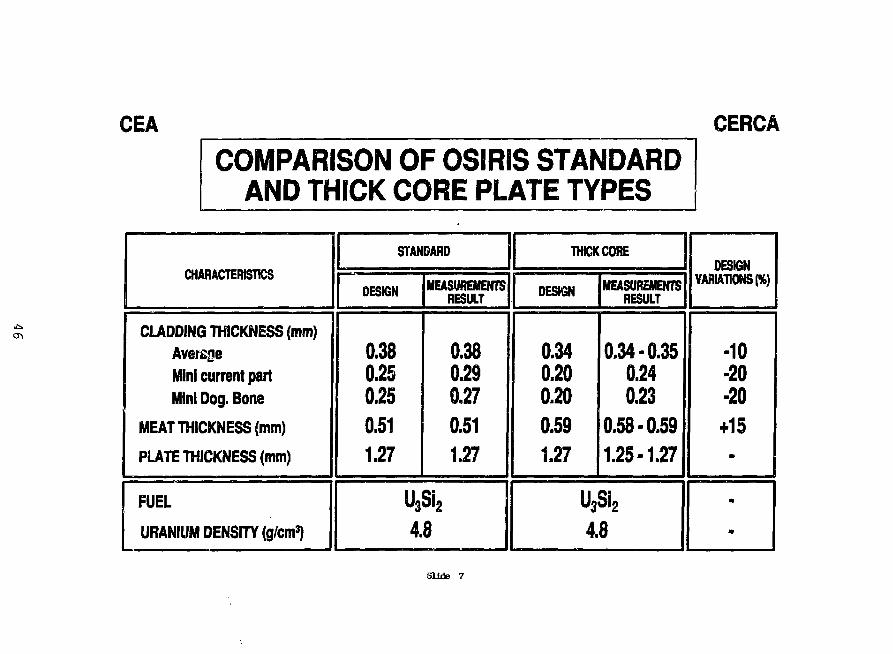
CEA CERCA
COMPARISON OF OSIRIS STANDARDAND THICK CORE PLATE TYPES
CHARACTERISTICS
CUDDING THICKNESS (mm)AverageMini current partMini Dog. Bone
MEAT THICKNESS (mm)
PLATE THICKNESS (mm)
FUEL
URANIUM DENSITY (g/cm3)
STANDARD
DESIGN
0.380.250.250.511.27
MEASUREMENTSRESULT
0.380.290.270.511.27
U3Si24.8
THICK CORE
DESIGN
0.340.200.200.591.27
MEASUREMENTSRESULT
0.34-0.350.240.23
0.58-0.591.25-1.27
U3Si24.8
DESIGNVARIATIONS (%)
-10-20-20+15
m
m
m
Slide 7
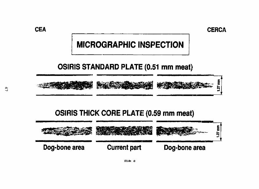
CEA CERCA
MICROGRAPHIC INSPECTION
OSIRIS STANDARD PLATE (0.51 mm meat)
OSIRIS THICK CORE PLATE (0.59 mm meat)
Dog-bone area Current part Dog-bone area
Slide 8
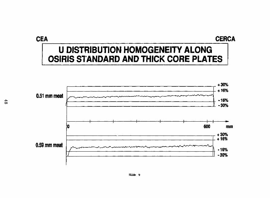
CEA CERCA
U DISTRIBUTION HOMOGENEITY ALONGOSIRIS STANDARD AND THICK CORE PLATES
00
0.51 mm meat
0.59 mm meat
4 30%+ 16%
-16%-30%
600 mm+ 30%+ 16%
[ -16%-30%
Slide 9
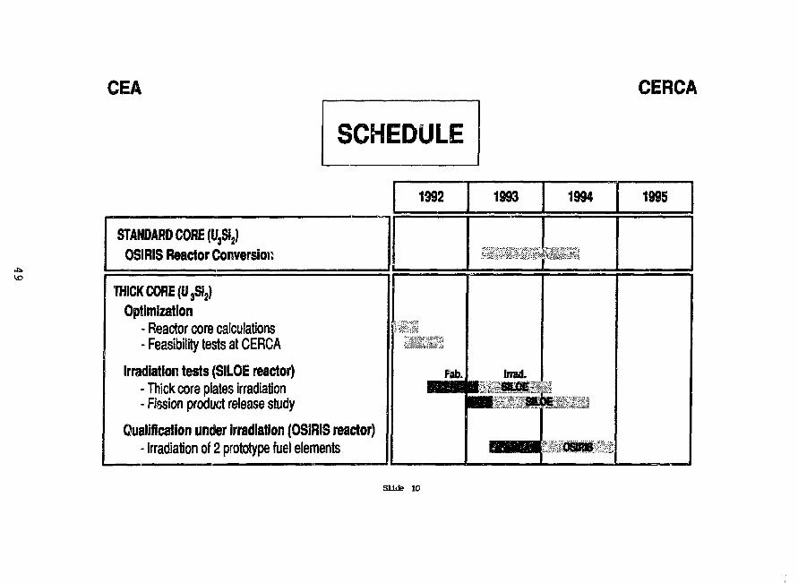
CEA CERCA
10
SCHEDULE
STANDARD CORE (U3Si2)OSIRIS Reactor Conversion
THICK CORE (U3Si2)Optimization
- Reactor core calculations-Feasibility tests at CERCA
Irradiation tests (SILOE reactor)- Thick core plates irradiation- Fission product release study
Qualification under irradiation (OSIRIS reactor)- irradiation of 2 prototype fuel elements
1992
Fab.
!
1993
brad.
m a*.
1994
osoas :
1995
Sliife 10
DEVELOPMENT OF HIGHER DENSITY FUEL AT CERCAStatus as of Nov.92
.P. DURAND - Y. FANJAS - A. TISSIERCERCA
Les Berauds - BP 111426104 Romans-Sur Isere, France
ABSTRACT
CERCA has initiated a fundamental research program forbetter understanding the behaviour of materials during the fuelplate manufacturing process. Thanks to a major breakthrough and acareful and systematic experimental validation of fabricationparameters, CERCA succeeded to set up an advanced productionprocess adapted to high densities up to 6 g Uip/cm. Thefabrication test was carried out on full size plates with pureU3Si2 in industrial conditions (on 50 plates). Next developmentsteps include checking the stability of obtained results on largescale production and evaluating the cost increase due to the useof advanced process. Furthermore irradiation tests are necessaryto qualify the 6 g density in reactor.
1. INTRODUCTION
During the last RERTR meeting, several customers haveexpressed their wish for a Uranium density increase above thepresently qualified limit of 4,8 g UT/cm
3 LEU fuel.
Aiming at further improving the quality of its products,CERCA had initiated a fundamental research program for a betterunderstanding of the materials behaviour during the fuel platemanufacturing process.
Taking into account its customer's request, CERCAreoriented this program to reach, in a first step, asignificantly higher uranium density.
50
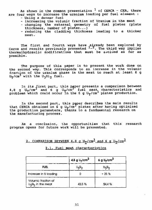
As shown in the common presentation ^ of CERCA - CEA, thereare four ways to increase the uranium loading per fuel element :
- Using a denser fuel- increasing the volumic fraction of Uranium in the meat- changing the external geometry of fuel plates (platethickness, number of plates...)
- reducing the cladding thickness leading to a thickermeat.
The first and fourth ways have already been explored byCerca and results previously presented - . The third way impliesthermalhydraulic modifications that must be avoided as far aspossible.
The purpose of this paper is to present the work done onthe second way. This corresponds to an increase in the volumicfraction of the uranium phase in the meat to reach at least 6 gUT/cm
3 with the U3Si2 fuel.
In its .first part, this paper presents a comparison between4,8 g UT/cm
3 and 6 g Um/cm3 fuel meat characteristics andproblems which could occur in the 6 g UT/cm
3 plates production.
In the second part, this paper describes the main resultsthat CERCA obtained on 6 g UT/cm
3 plates after having optimizedthe production parameters, tnanks to a fundamental research onthe manufacturing process.
As a conclusion, the opportunities thatprogram opens for future work will be presented.
this research
2. COMPARISON BETWEEN 4,8 q U^cm3- and 6 q Urp/cm3-
2.1. Fuel meat characteristics
FUEL
Increase in U loading
Volumic fraction ofUgS^ in the meat
4,8 g UT/cm3
U3Si2
0
43.5 %
6 g UT/cm3
u3si2
+ 25 %
54,4%
51
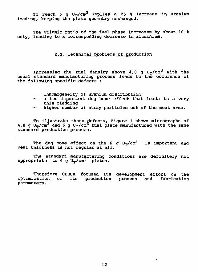
To reach 6 g Um/cm^ implies a 25 % increase in uraniumloading, keeping the plate geometry unchanged.
The volumic ratio of the fuel phase increases by about 10 %only, leading to a corresponding decrease in aluminium.
2.2. Technical problems of production
Increasing the fuel density above 4,8 g UT/cnr with theusual standard manufacturing process leads to the occurence ofthe following specific defects :
inhomogeneity of uranium distributiona too important dog bone effect that leads to a verythin claddinghigher number of stray particles out of the meat area.
To illustrate those defects, Figure 1 shows micrographs of4,8 g Um/cnr and 6 g UT/cm
3 fuel plate manufactured with the samestandard production process.
The dog bone effect on the 6 g UT/cm^ is important andmeat thickness is not regular at all.
The standard manufacturing conditions are definitely notappropriate to 6 g UT/cm
3 plates.
Therefore CERCA focused its development effort on theoptimization of its production process and fabricationparameters.
52
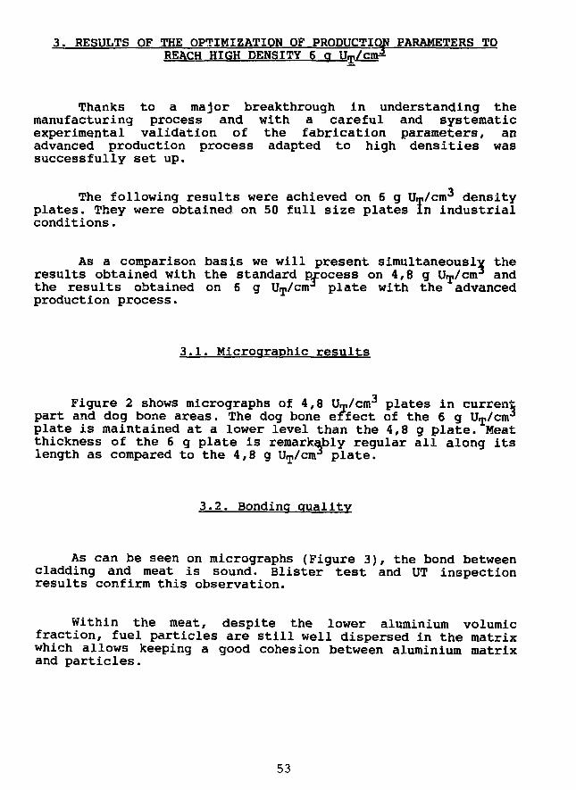
3. RESULTS OF THE OPTIMIZATION OF PRODUCTION PARAMETERS TOREACH HIGH DENSITY 6 a UT/cn3
Thanks to a major breakthrough in understanding themanufacturing process and with a careful and systematicexperimental validation of the fabrication parameters, anadvanced production process adapted to high densities wassuccessfully set up.
The following results were achieved on 6 g Um/cm^ densityplates. They were obtained on 50 full size plates in industrialconditions.
As a comparison basis we will present simultaneously theresults obtained with the standard process on 4,8 g Uip/cm3 andthe results obtained on 6 g UT/cm
3 plate with the advancedproduction process.
3.1. Microqraphic results
Figure 2 shows micrographs of 4,8 UT/cm3 plates in current
part and dog bone areas. The dog bone effect of the 6 g V^/aarplate is maintained at a lower level than the 4,8 g plate. Meatthickness of the 6 g plate is remarkably regular all along itslength as compared to the 4,8 g UT/cnr* plate.
3.2. Bonding quality
As can be seen on micrographs (Figure 3), the bond betweencladding and meat is sound. Blister test and UT inspectionresults confirm this observation.
Within the meat, despite the lower aluminium volumicfraction, fuel particles are still well dispersed in the matrixwhich allows keeping a good cohesion between aluminium matrixand particles.
53
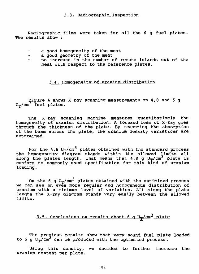
3.3. Radioqraphic inspection
Radiographic films were taken for all the 6 g fuel plates.The results show :
a good homogeneity of the meata good geometry of the meatno increase in the number of remote islands out of themeat with respect to the reference plates.
3.4. Homogeneity of uranium distribution
Eigure 4 shows X-ray scanning measurements on 4,8 and 6 gUip/crrr fuel plates.
The X-ray scanning machine measures quantitatively thehomogeneity of uranium distribution. A focused beam of X-ray goesthrough the thickness of the plate. By measuring the absorptionof the beam across the plate, the uranium density variations aredetermined.
For the 4,8 Um/cm3 plates obtained with the standard processthe homogeneity diagram stands within the allowed limits allalong the plates length. That means that 4,8 g Um/cm3 plate isconform to commonly used specification for this kind of uraniumloading.
On the 6 g UT/cm plates obtained with the optimized processwe can see an even more regular and homogeneous distribution ofuranium with a minimum level of variation. All along the platelength the X-ray diagram stands very easily between the allowedlimits.
3.5. Conclusions on results about 6 q U^/cm— plate
The previous results show that very sound fuel plate loadedto 6 g UT/cm
3 can be produced with the optimized process.
Using this density, we decided to further increase theuranium content per plate.
54
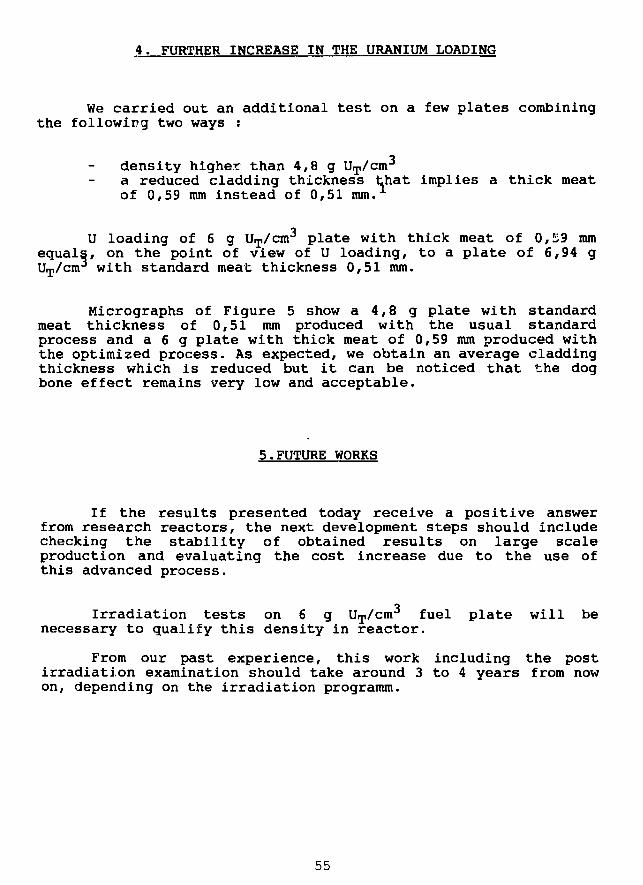
4. FURTHER INCREASE IN THE URANIUM LOADING
We carried out an additional test on a few plates combiningthe following two ways :
density higher than 4,8 g UT/cm3
a reduced cladding thickness that implies a thick meatof 0,59 mm instead of 0,51 mm.
U loading of 6 g UT/cm3 plate with thick meat of 0,23 mm
equals, on the point of view of U loading, to a plate of 6,94 gUT/cm
3 with standard meat thickness 0,51 mm.
Micrographs of Figure 5 show a 4,8 g plate with standardmeat thickness of 0,51 mm produced with the usual standardprocess and a 6 g plate with thick meat of 0,59 mm produced withthe optimized process. As expected, we obtain an average claddingthickness which is reduced but it can be noticed that the dogbone effect remains very low and acceptable.
5.FUTURE WORKS
If the results presented today receive a positive answerfrom research reactors, the next development steps should includechecking the stability of obtained results on large scaleproduction and evaluating the cost increase due to the use ofthis advanced process.
Irradiation tests on 6 g UT/cm3 fuel plate will be
necessary to qualify this density in reactor.
From our past experience, this work including the postirradiation examination should take around 3 to 4 years from nowon, depending on the irradiation programm.
55
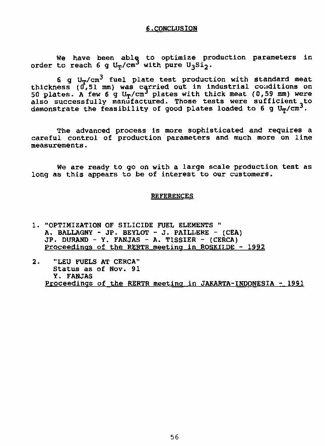
6.CONCLUSION
We have been able to optimize production parameters inorder to reach 6 g UT/cm
3 with pure U3Si2.
6 g UT/cm3 fuel plate test production with standard meat
thickness (0,51 mm) was carried out in industrial conditions on50 plates. A few 6 g UT/cm
3 plates with thick meat (0,59 mm) werealso successfully manufactured. Those tests were sufficient todemonstrate the feasibility of good plates loaded to 6 g UT/cm .
The advanced process is more sophisticated and requires acareful control of production parameters and much more on linemeasurements.
We are ready to go on with a large scale production test aslong as this appears to be of interest to our customers.
REFERENCES
1. "OPTIMIZATION OF SILICIDE FUEL ELEMENTS "A. BALLAGNY - JP. BEYLOT - J. PAILLERE - (CEA)JP. DURAND - Y. FANJAS - A. TISS1ER - (CERCA)Proceedings of the RERTR meeting in ROSKILDE - 1992
2. "LEU FUELS AT CERCA"Status as of Nov. 91Y. FANJAS
Proceedings of the RERTR meeting in JAKARTA-INDONESIA - 1991
56
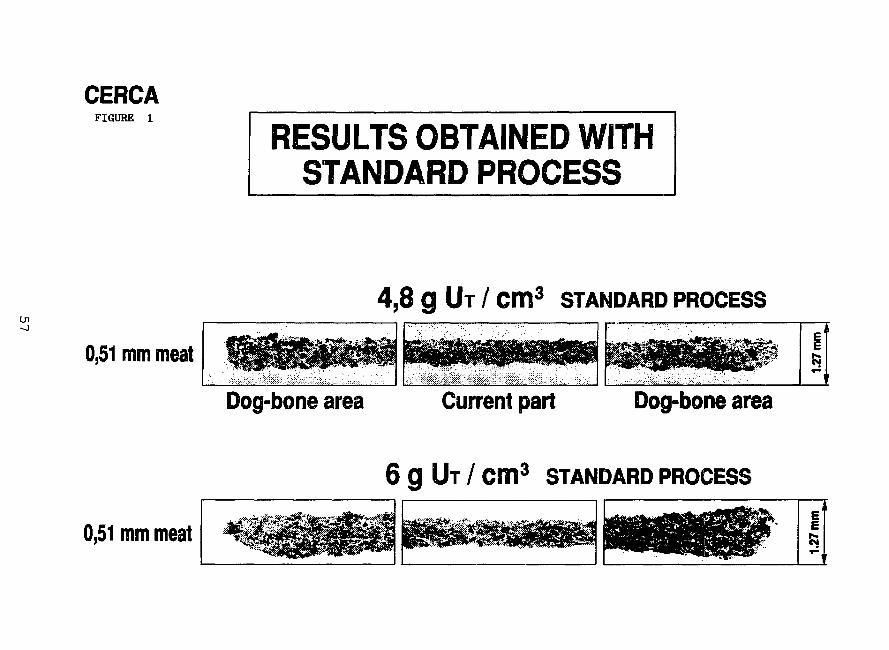
CERCAFIGURE 1
RESULTS OBTAINED WITHSTANDARD PROCESS
Ui
4,8 g UT / cm3 STANDARD PROCESS
0,51 mm meat
Dog-bone area Current part Dog-bone area
6 g UT / cm3 STANDARD PROCESS
0,51 mm meat
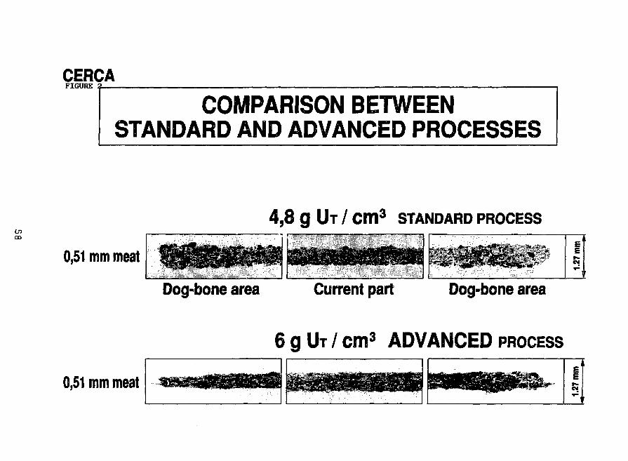
CERCAFIGURE
COMPARISON BETWEENSTANDARD AND ADVANCED PROCESSES
CnCO
4,8 g UT / cm3 STANDARD PROCESS
0,51 mm meat£
Dog-bone area Current part Dog-bone area
6 g UT / cm3 ADVANCED PROCESS
0,51 mm meatE
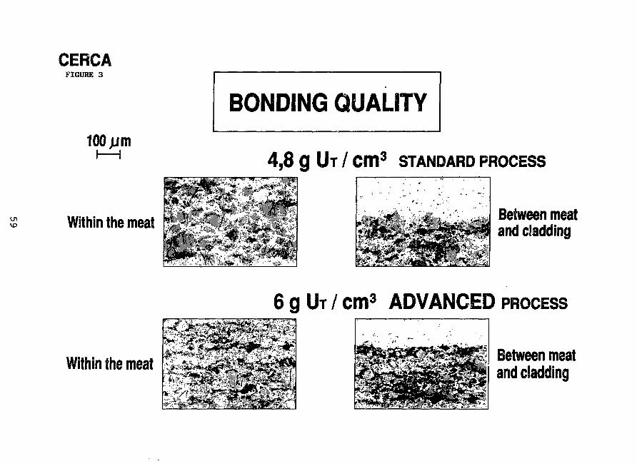
CERCAFIGURE 3
100 j jm
Within the meat
Within the meat
BONDING QUALITY
4,8 g UT / cm3 STANDARD PROCESS
Between meatand cladding
6 g UT / cm3 ADVANCED PROCESS
Between meat
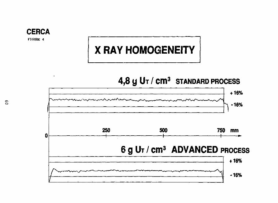
CERCAFIGURE 4
X RAY HOMOGENEITY
4,8 y UT / cm3 STANDARD PROCESS
V4-16%
16%
250—h-
500 750 mm
6 g UT / cm3 ADVANCED PROCESS+ 16%
^-Ai16%
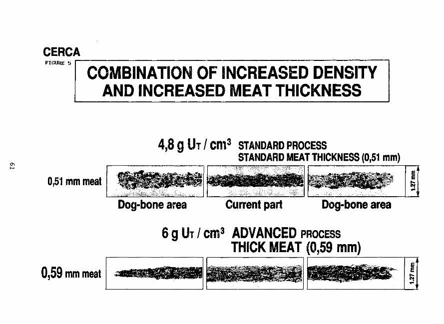
CERCAFIGURE 5
COMBINATION OF INCREASED DENSITYAND INCREASED MEAT THICKNESS
4,8 g l h / cm3 STANDARD PROCESSSTANDARD MEAT THICKNESS (0,51 mm)
0,51 mm meatE
Dog-bone area Current part Dog-bone area
6 g UT / cm3 ADVANCED PROCESSTHICK MEAT (0,59 mm)
0,59 mm meat £
CERCA IS CHANGING ITS SHAREHOLDING
JP. DurandCERCA
The shareholding of CERCA, previously 50% Framatome and 50%Pechiney is becoming 51% Framatome and 49% Cogema. This newdistribution of the shares offers Framatome the position of majorshareholder. This evolution strengthens the position of CERCA in theFrench nuclear industry while maintaining its specificity as amanufacturer of nuclear fuel assemblies and special equipments forresearch reactors, as well as a designer and manufacturer of complexmechanisms for use in large equipments for physics of particles andfundamental research.
Three main advantages should be underlined in this change:
1. Continuity in the company as regards persons, plants,commercial network and R U D programs. CERCA is keeping itsorganization and its operational fabrication and sales structure. Inparticular, the R & D programs are carried on to serve customers.Moreover, CERCA maintains its commercial network in order to continueto offer customers competent, flexible, and quick service.
2 . Synergy and logistical support which CERCA will receive fromits shareholders. Framatome is equipped with specialized means in thefollowing fields:
engineering and calculation departmentsspecialized studies: Such as resistance of materials,
modelization, safety studies, support in metallurgy and inassembling techniqj.es.
Framatome Engineering services are most adequate to study, onbehalf of CERCA's customers, design modification, or new projectsinteresting research reactor operators.
Cogema supports Cerca in certain services relaced to the fissilematerial: As an example, CERCA signed with Cogema an agreement whichallows Cerca, in addition to its own means of scraps recycling, tosubcontract special uranium recycling operations to Cogema's chemicalfacilities. Moreover, Cogema can, on demand, ensure supply of fissilematerial.
3. At last especially the service to customers in a spirit ofindependence and technical progress. It has to be underlined thatCerca, a humanly dimensioned company specialized in the field ofresearch reactors ensures its customers the independent services theymay wish, adapted to their specific needs. In the frame ofinternational rules, Cerca guarantees confidentiality and safety toits customers.
62
QUALITY ASSURANCE AND ULTRASONIC INSPECTION STUDIES IN LEU FUELPRODUCTION
P. Toft, J. Borring, E. Adolph, T.M. NilssonRis0 National Laboratory, Denmark
ABSTRACT
In connection with the efforts to market Low Enriched Uranium FuelElements internationally, a Quality Assurance System for the productionat Risa National Laboratory, Materials Department is described. Thedepartment has established a Quality Assurance program to comply with theapplicable clauses and elements of the ISO 9002 standard. As a specialfeature, the development of Ultrasonic Scanning Techniques for detectionof blisters and measuring layer thicknesses are described.
INTRODUCTION
Fabrication of fuel elements for test reactors was started at Ris0National Laboratory in 1965. In 1988, the production of LEU fuelelements based on U3Si2, began in the Materials Department. At present,200 LEU fuel elements have been produced, of which about 100 have nowcompleted irradiation in the Danish test reactor, DR3, all of themsuccessfully.
The LEU fuel elements which are produced at iliss are made inaccordance with the recommendations given in the IAEA guidebook TECDOC-467: "Standardization of Specifications and Inspection Procedures forLEU Plate Type Research Reactor Fuels." Our Quality Control and QualityAssurance procedures comprise a well functioning system, which in allmajor parts complies with the requirements in the ISO 9002 Standard.
This paper provides a brief presentation of our QA system and anUltrasonic Scanning Technique for detection of blisters and measuring oflayer thicknesses in fuel plates.
63
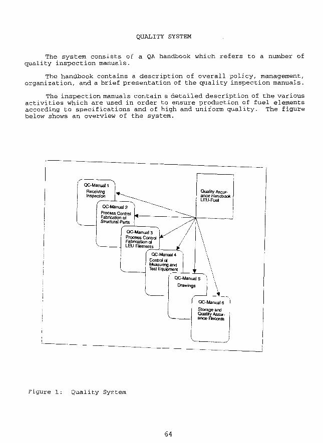
QUALITY SYSTEM
The system consists of a QA handbook which refers to a number ofquality inspection manuals.
The handbook contains a description of overall policy, management,organization, and a brief presentation of the quality inspection manuals.
The inspection manuals contain a detailed description of the variousactivities which are used in order to ensure production of fuel elementsaccording to specifications and of high and uniform quality. The figurebelow shows an overview of the system.
Quality Ascuf-anoe HandbookLEU-Fuel
ReceivingInspection
QC-Manual2Process ControlFabrication ofStructural Parts
QC-Manual3Process ControlFabrication ofLEU Elements
QC-Manual 4Control ofMeasuring andTest Equipment
QC-Manual 5
Drawings
Storage andQuality Assur-ance Records
Figure 1: Quality System
64
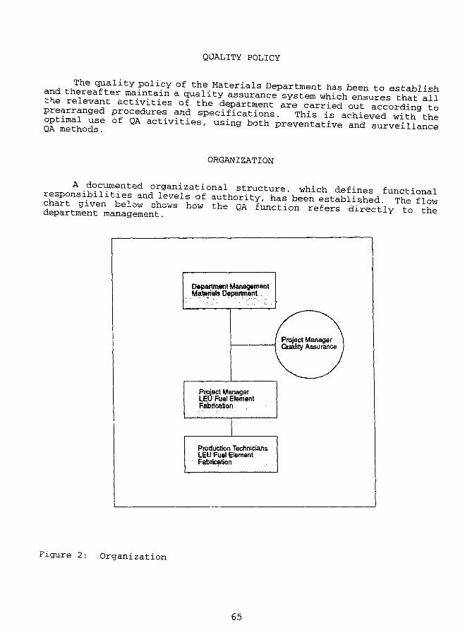
QUALITY POLICY
3TiH .Jif ̂ .ality P°licY of the Materials Department has been to establishand thereafter maintain a quality assurance system which ensures t h t f 1
using both preventive and surveillance
ORGANIZATION
A documented organizational structure, which defines functional
t i ^ " * level" o f authority, has been established The ?low^ 3 h ° W " * Q A f U n C t i ° n r e f e r S d i r t 1 to the
Department ManagementMateriate Department
Project ManagerQuality Assurance
Project ManagerLEU Fuel ElementFabrication
Production TechniciansLEU fuel Elementfabrication
Figure 2: Organization
65
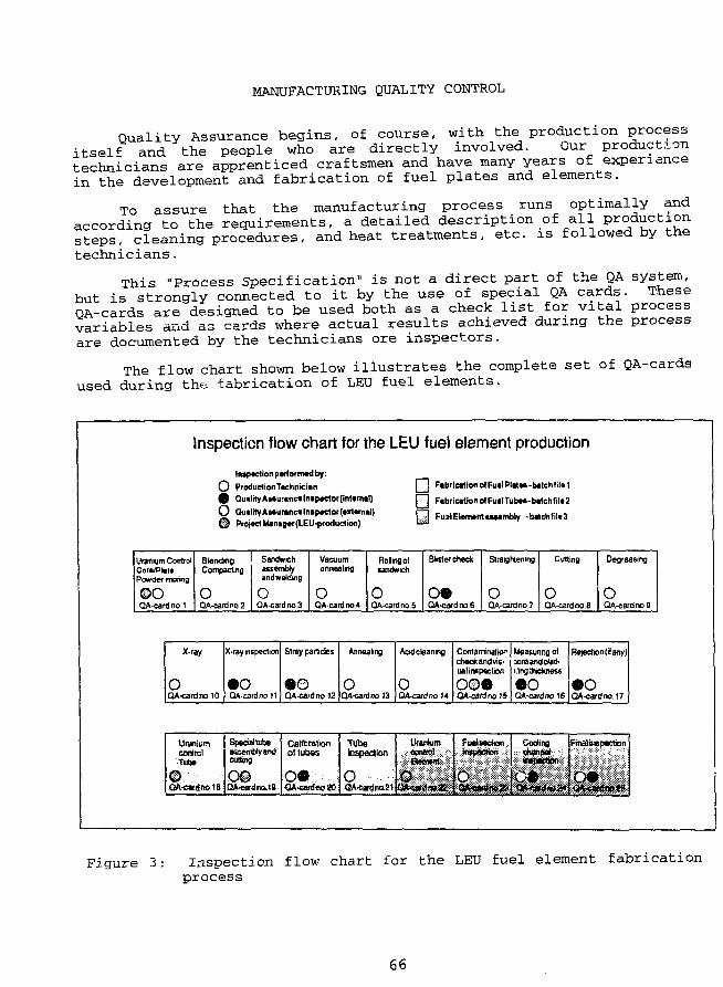
MANUFACTURING QUALITY CONTROL
Quality Assurance begins, of course, with the production processitself and the people who are directly involved. Our productiontechnicians are apprenticed craftsmen and have many years of experi ancein the development and fabrication of fuel plates and elements.
To assure that the manufacturing process runs optimally andaccording to the requirements, a detailed description of all productionsteps, cleaning procedures, and heat treatments, etc. is followed by thetechnicians.
This "Process Specification" is not a direct part of the QA system,but is strongly connected to it by the use of special QA cards. TheseQA-cards are designed to be used both as a check list for vital processvariables and as cards where actual results achieved during the processare documented by the technicians ore inspectors.
The flow chart shown below illustrates the complete set of QA-cardsused during the fabrication of LEU fuel elements.
Inspection flow chart for the LEU fuel element production
Inaptction parlornwj by:
O ProdudionTachnkian
Q QuilrtyAaauranc*lnap«tor(imernal)
O OualityAaaurancalnapador(aitamal)
© Project Manag«(LEU-produclion)
DaH
Fabrication otFuelPlatea-batchfilei
Fabrication ofFualTubaa-batchfilai
Fu j i Element asaambly -b«tchfil«3
Uranium ControlCora/PielePowder mixing
©oQA-canj no 1
Blond POOCompacting
oQA-card no 2
Sandwichassemblyandwelding
oQA-card no 3
Vacuumannealing
oQA-card no 4
Rolling ofsandwich
0QA-card no.5
Blister check
QA-card no 6
Straightening
0QA-card no 7
Cutting
OQA-card no 8
Decreasing
oQA-card no 9
X-ray
OQA-card no 10
|X-rey inspection!
•oQA-card no I t
Stray panicles
QA-card no 12
Annealing
oQA-cardno 13
Acid cleaning
oQA-card no H
Contamination | Measunng olcheokand vis-ual inspection
o©eQA-card no 15
sore and ciad-ilingihickness
•oQA-cardno IS
Rejection (if any)!
•oQA-cardno 17
Uraniumcontra!Tube
© • • • • • • • : • :
QA-c»rdno13
Special tubeasssmblyandcutting
o#DA-tffldnoIB
Calibrationol tubas
W-carfftoJO
TubeInspection
O :,QA-card nq.21
Ufinwm
iSjiiEwfflWf;:;;;^
Fuelsedion .
:::;>:r;::::::^:::::::':-:vii%'::::
C o o l i n a . . .
iiliiFnialinspcction
illilllllii
Figure 3: Inspection flow chart for the LEU fuel element fabricationprocess
66
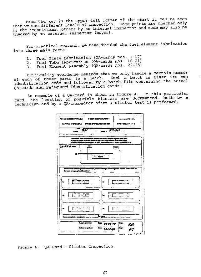
From the key in the upper left corner of the chart it can be seenthat we S e different levelfof inspection. Some points are checked onlyby the technicians, others by an internal inspector and some may also bechecked by an external inspector (buyer).
For practical reasons, we have divided the fuel element fabricationinto three main parts:
1 Fuel Plate fabrication (QA-cards nos. 1-17)2 Fuel Tube fabrication (QA-cards nos. 18-21)3. Fuel Element assembly (QA-cards nos. 22-25)
Criticality avoidance demands that we only handle a certain numberof each of these parts in a batch. Such a batch is given its owntestification ?ode and followed by a batch file containing the actualQA-cards and Safeguard Identification cards.
An example of a QA-card is shown in figure 4. In this particularcard <-he location of possible blisters are documented, both by atechnician and by a QA-inspector after a blister test is performed.
UATERW-EFOOSKMNQ
PMCCKOMTIMLKORT
DM tfUEWtELKLEIEHTEIt
BLETEBKOfJTROt
KCMTROLKORT W a
•ast
I k I----. ::?:;:v;":;,]
JPOr. f -:•:,:;::-::]
I
)
Mr. 1 .-.:--::i; -1
Mr. 1 . • • • • . . . !
1 _J
Mr. 1 : . 1)
J
Figure 4: QA Card - Blister Inspection.
67
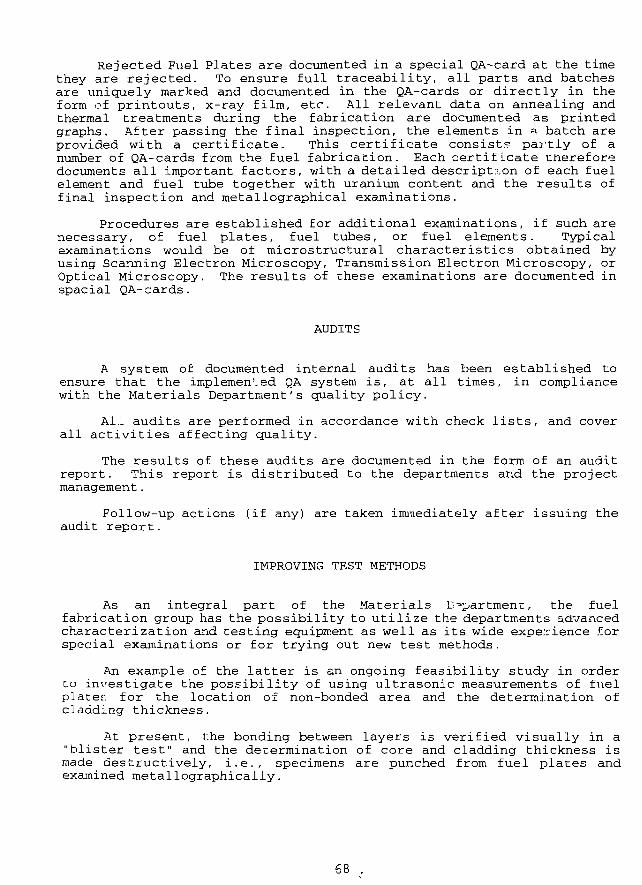
Rejected Fuel Plates are documented in a special QA-card at the timethey are rejected. To ensure full traceability, all parts and batchesare uniquely marked and documented in the QA-cards or directly in theform of printouts, x-ray film, etc. All relevant data on annealing andthermal treatments during the fabrication are documented as printedgraphs. After passing the final inspection, the elements in » batch areprovided with a certificate. This certificate consist? partly of anumber of QA-cards from the fuel fabrication. Each certificate thereforedocuments all important factors, with a detailed description of each fuelelement and fuel tube together with uranium content and the results offinal inspection and metallographical examinations.
Procedures are established for additional examinations, if such arenecessary, of fuel plates, fuel tubes, or fuel elements. Typicalexaminations would be of microstructural characteristics obtained byusing Scanning Electron Microscopy, Transmission Electron Microscopy, orOptical Microscopy. The results of these examinations are documented inspacial QA-cards.
AUDITS
A system of documented internal audits has been established toensure that the implemented QA system is, at all times, in compliancewith the Materials Department's quality policy.
ALL audits are performed in accordance with check lists, and coverall activities affecting quality.
The results of these audits are documented in the form of an auditreport. This report is distributed to the departments and the projectmanagement.
Follow-up actions (if any) are taken immediately after issuing theaudit report.
IMPROVING TEST METHODS
As an integral part of the Materials Department, the fuelfabrication group has the possibility to utilize the departments advancedcharacterization and testing equipment as well as its wide experience forspecial examinations or for trying out new test methods.
An example of the latter is an ongoing feasibility study in orderto investigate the possibility of using ultrasonic measurements of fuelplaten for the location of non-bonded area and the determination ofcladding thickness.
At present, the bonding between layers is verified visually in a"blister test" and the determination of core and cladding thickness ismade destructively, i.e., specimens are punched from fuel plates andexamined metallographically.
68 .
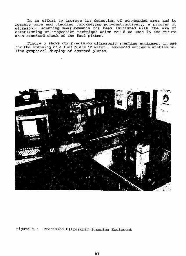
In an effort to improve t'hs detection of non-bonded area and tomeasure core and cladding thicknesses non-destructively, a program ofultrasonic scanning measurements has been initiated with the aim ofestablishing an inspection technique which could be used in the futureas a standard check of the fuel plates.
Figure 5 shows our precision ultrasonic scanning equipment in usefor the scanning of a fuel plate in water. Advanced software enables on-line graphical display of scanned plates.
Figure 5.: Precision Ultrasonic Scanning Equipment
69
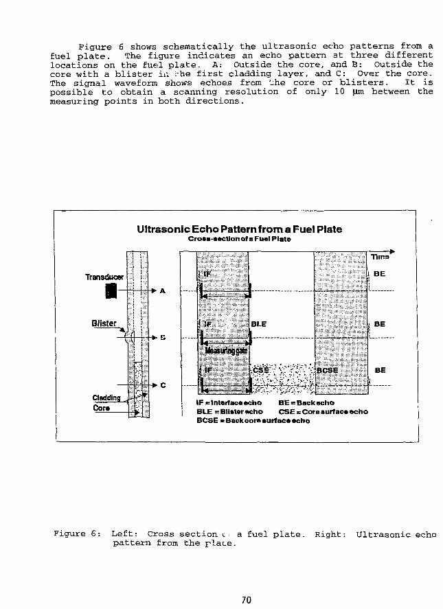
Figure 6 shows schematically the ultrasonic echo patterns from afuel plate. The figure indicates an echo pattern at three differentlocations on the fuel plate. A: Outside the core, and B: Outside thecore with a blister in :-he first cladding layer, and C: Over the core.The signal waveform shows echoes from '_he core or blisters. It ispossible to obtain a scanning resolution of only 10 |xm between themeasuring points in both directions.
Ultrasonic Echo Pattern from a Fuel PlateCross-section of a Fuel Plate
Transducer
Cladding „Core
1̂ 1*• c
mmmm
iSlili BLE
Tlina
BE
BE
IF «= Interface echo BE = Back echoBLE = Blister echo CSE = Core surface echoBCSE s Back cora surface echo
Figure 6: Left: Cross section t, a fuel plate. Right: Ultrasonic echopattern from the plate.
70
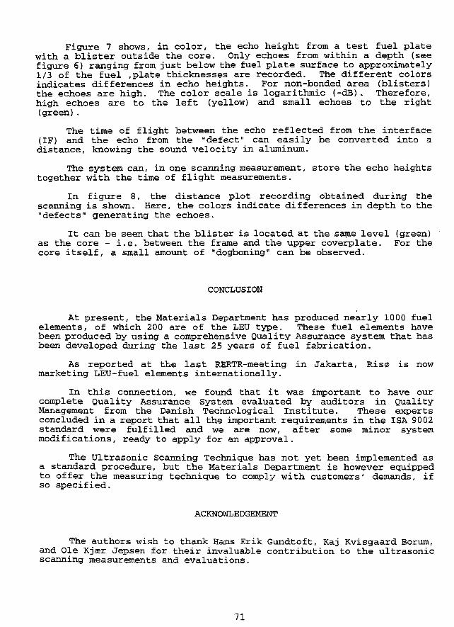
Figure 7 shows, in color, the echo height from a test fuel platewith a blister outside the core. Only echoes from within a depth (seefigure 6) ranging from just below the fuel plate surface to approximately1/3 of the fuel ,plate thicknesses are recorded. The different colorsindicates differences in echo heights. For non-bonded area (blisters)the echoes are high. The color scale is logarithmic (-dB). Therefore,high echoes are to the left (yellow) and small echoes to the right(green).
The time of flight between the echo reflected from the interface(IF) and the echo from the "defect" can easily be converted into adistance, knowing the sound velocity in aluminum.
The system can, in one scanning measurement, store the echo heightstogether with the time of flight measurements.
In figure 8, the distance plot recording obtained during thescanning is shown. Here, the colors indicate differences in depth to the"defects" generating the echoes.
It can be seen that the blister is located at the same level (green)as the core - i.e. between the frame and the upper coverplate. For thecore itself, a small amount of "dogboning" can be observed.
CONCLUSION
At present, the Materials Department has produced nearly 1000 fuelelements, of which 200 are of the LEU type. These fuel elements havebeen produced by using a comprehensive Quality Assurance system that hasbeen developed during the last 25 years of fuel fabrication.
As reported at the last RERTR-meeting in Jakarta, Ris© is nowmarketing LEU-fuel elements internationally.
In this connection, we found that it was important to have ourcomplete Quality Assurance System evaluated by auditors in QualityManagement from the Danish Technological Institute. These expertsconcluded in a report that all the important requirements in the ISA 9002standard were fulfilled and we are now, after some minor systemmodifications, ready to apply for an approval.
The Ultrasonic Scanning Technique has not yet been implemented asa standard procedure, but the Materials Department is however equippedto offer the measuring technique to comply with customers' demands, ifso specified.
ACKNOWLEDGEMENT
The authors wish to thank Hans Erik Gundtoft, Kaj Kvisgaard Borum,and Ole Kjeer Jepsen for their invaluable contribution to the ultrasonicscanning measurements and evaluations.
71
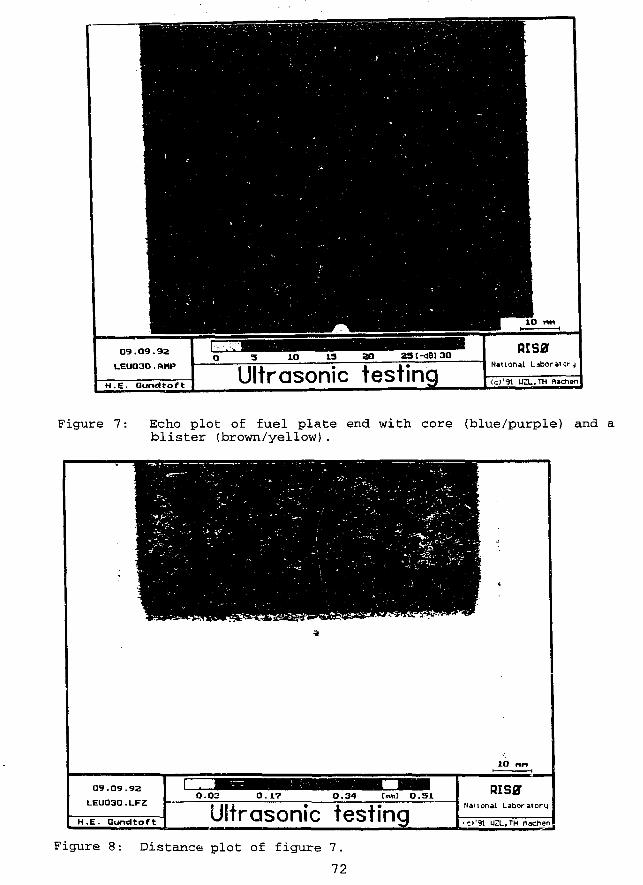
Ultrasonic testing
Figure 7: Echo plot of fuel plate end with core (blue/purple) and ablister (brown/yellow).
10
09.09.9Z
LEUO3O.LFZ
H.E. Gundtoft
0.03 0.17 0.51
Ultrasonic testingRiser
National Laboratory
O'91 UZL,TH flachen
Figure 8: Distance plot of figure 7.
72
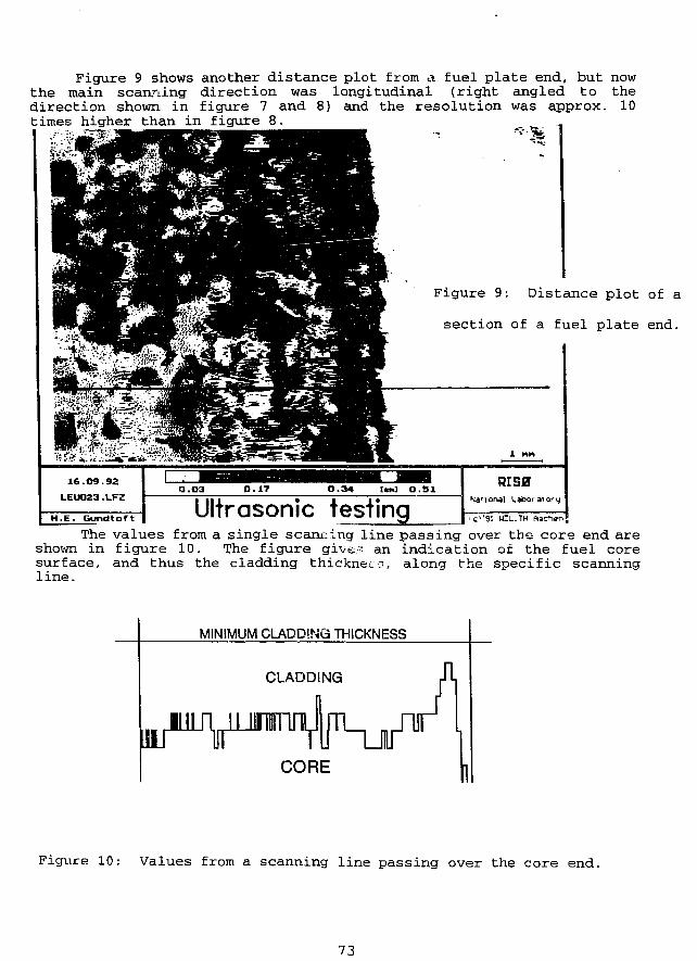
Figure 9 shows another distance plot from a fuel plate end, but nowthe main scanning direction was longitudinal (right angled to thedirection shown in figure 7 and 8) and the resolution was approx. 10times higher than in figure 8.
Figure 9: Distance plot of a
section of a fuel plate end.
1 nn
16.O9.93LEU023.LFZ
H.E. Gundtoft
O.O3 0.17 O.34 Cum] O . 5 1
Ultrasonic testingRiser
National Labor a'or
'(:••'91 U"L.TH ftacher
The values from a single scanning line passing over the core end areshown in figure 10. The figure give- an indication of the fuel coresurface, and thus the cladding thickness, along the specific scanningline.
MINIMUM CLADDING THICKNESS
CLADDING
CORE
Figure 10: Values from a scanning line passing over the core end.
73
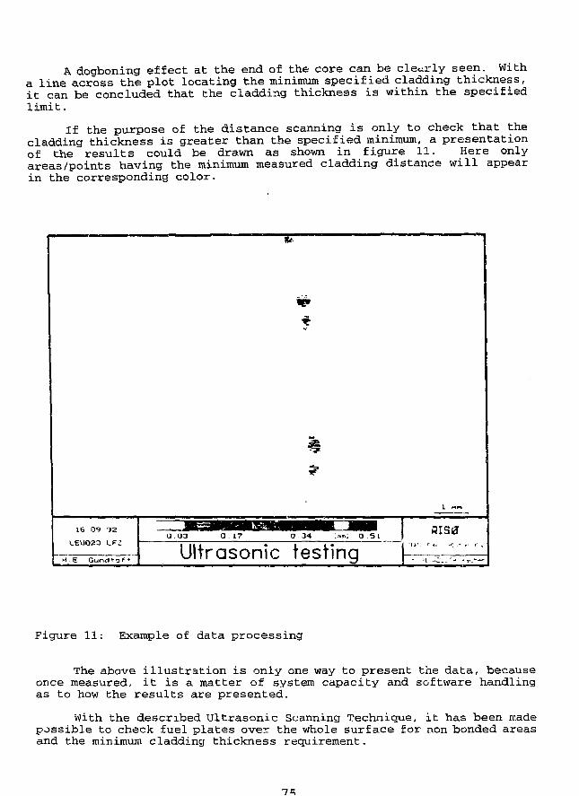
A dogboning effect at the end of the core can be clearly seen. Witha line across the plot locating the minimum specified cladding thickness,it can be concluded that the cladding thickness is within the specifiedlimit.
If the purpose of the distance scanning is only to check that thecladding thickness is greater than the specified minimum, a presentationof the results could be drawn as shown in figure 11. Here onlyareas/points having the minimum measured cladding distance will appearin the corresponding color.
16.09 92
LEUO23 LFZ
H . 6 Qunei * o f f
0 .34 HIS0
Ultrasonic testing
Figure 11: Example of data processing
The above illustration is only one way to present the data, becauseonce measured, it is a matter of system capacity and software handlingas to how the results are presented.
With the described Ultrasonic Scanning Technique, it has been madepossible to check fuel plates over the whole surface for non bonded areasand the minimum cladding thickness requirement.
CHARACTERIZATION OF ATOMIZED U,Si2 POWDER FORRESEARCH REACTOR*
CXKim, K.H.Kim, S.JJang. H.DJo, I.H.KukKorea Atomic Energy Research Institute
Daeduk-Danji, Taejon, Korea,
ABSTRACT
Atomization technique was developed to produce U3Si2 powderusing rotating disk. It was found that the atomized U3Siz powder hasspherical shape and smooth surface. Surface area of atomizedpowder is smaller by about 30% than that of comminuted powder.Only U3Si2 peaks appear on X-ray diffraction of atomized powderand the second phase ex^ts with a small fraction and thin widthon microstructure observation. It is also noticed that the atomizedU3Si2 powder has homogeneous U3Si2 phase. Characteristics ofatomized U3Si2 powder, i.e., spherical shape, smooth surface andhomogeneous phase formation, are expected to give improvementsin fabrication and to the properties of research reauor fuel.
INTRODUCTION
Rotating disk atomizing technique was applied to the fabrication of KMRR fuei inorder to overcome the difficulties in comminuting tough U3Si billet, to eliminate theimpurities and to obtain rapidly solidified spherical powder. As a result, fabricationprocess can be economized and the properties of the fuel can be improved.1)i2)
In fabrication of fuel plate where U3Si2 is dispersed in aluminum matrix, thespherical shaped U3Si2 powder can give desirable effects of improving plasticformability and homogenous dispersion. The dog boning can be eliminated in rollingthe fuel plate. Additionally, the surface area of U3Si2 particle is smaller than theirregular comminuted particle, so that the reaction swelling is expected to decrease.
U?Si atomization was presented in the last meeting. For the general application,U3Si2 is atomized in this year. U3Si2 alloy is meited at much higher temperature thanU3Si alloy. The liquid phase forms directly to the fine solid particle without passingthrough the two phase region of solid/liquid at 166512. The atomizing equipment was
76
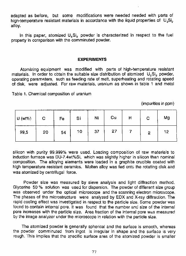
adapted as before, but some modifications were needed needed with parts ofhigh-temperature resistant materials in accordance with the liquid properties of U3Si2alloy.
In this paper, atomized U3Si2 powder is characterized in respect to the fuelproperty in comparison with the comminuted powder.
EXPERIMENTS
Atomizing equipment was modified with parts of high-temperature resistantmaterials. In order to obtain the suitable size distribution of atomized U3Si2 powder,operating parameters, such as feeding rate of melt, superheating and rotating speedof disk, were adjusted. For raw materials, uranium as shown in table 1 and metal
Table 1. Chemical composition of uranium
(impurities in ppm)
U (wt%)
99,5
C
20
Fe
54
Si
10
Ni
37
Cu
27
H
7 2
Mg
12
silicon with purity 99.999% were used. Loading composition of raw materials toinduction furnace was DU-7.4wt%Si, which was slightly higher in silicon than nominalcomposition. The alloying elements were loaded in a graphite crucible coated withhigh temperature resistant ceramics. Molten alloy was fed onto the rotating disk andwas atomized by centrifugal force.
Powder size was measured by sieve analysis and light diffraction method.Glycerine 50 % solution was used for dispersion. The powder of different size groupwas observed under the optical microscope and the scanning electron microscope.The phases of the microstructure were analyzed by EDX and X-ray diffraction. Therapid cooling effect was investigated in respect to the particle size. Some powder wasfound to contain internal pore. It was found that the number and size of the internalpore increases with the particle size. Area fraction of the internal pore was measuredby the image analyzer under the microscope in relation with the particle size.
The atomized powder is generally spherical and the surface is smooth, whereasthe powder comminuted from ingot is irregular in shape and the surface is veryrough. This implies that the specific surface area of the atomized powder is smaller
77
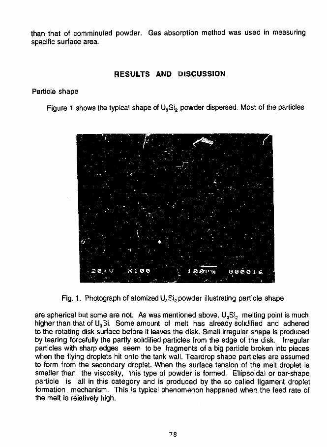
than that of comminuted powder. Gas absorption method was used in measuringspecific surface area.
RESULTS AND DISCUSSION
Particle shape
Figure 1 shows the typical shape of U3Si2 powder dispersed. Most of the particles
Fig. 1. Photograph of atomized U3Sia powder illustrating particle shape
are spherical but some are not. As was mentioned above, U3Si2 melting point is muchhigher than that of U3Si. Some amount of melt has already solidified and adheredto the rotating disk surface before it leaves the disk. Small irregular shape is producedby tearing forcefully the partly solidified particles from the edge of the disk. Irregularparticles with sharp edges seem to be fragments of a big particle broken into pieceswhen the flying droplets hit onto the tank wall. Teardrop shape particles are assumedto form from the secondary droplet. When the surface tension of the melt droplet issmaller than the viscosity, this type of powder is formed. Ellipsoidal or bar-shapeparticle is all in this category and is produced by the so called ligament dropletformation, mechanism. This is typical phenomenon happened when the feed rate ofthe melt is relatively high.
78
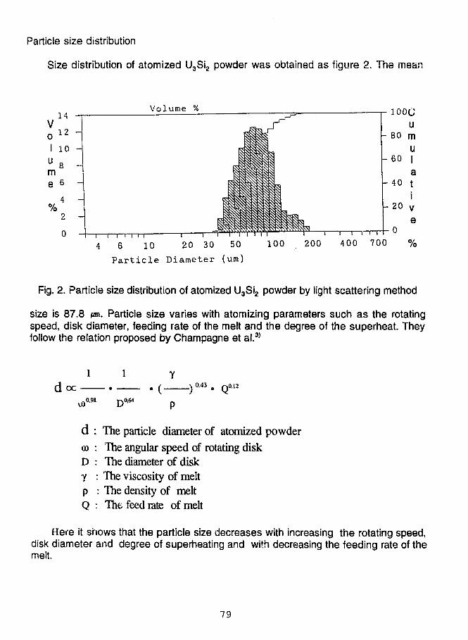
Particle size distribution
Size distribution of atomized U3Si2 powder was obtained as figure 2. The mean
14Volume %
"i—i—i i i i 1 r
4 6 10 20 30 50 100 . 200Part ic le Diameter (um)
Fig. 2. Particle size distribution of atomized U3Si2 powder by light scattering method
size is 87.8 JOT. Particle size varies with atomizing parameters such as the rotatingspeed, disk diameter, feeding rate of the melt and the degree of the superheat. Theyfollow the relation proposed by Champagne et al.3)
1 1doc ) 0 4 3 • Q012
u>0-98 D 0 M p
d : The particle diameter of atomized powder
© : The angular speed of rotating disk
D : The diameter of disk
Y : The viscosity of melt
p : The density of melt
Q : The feed rate of melt
Here it shows that the particle size decreases with increasing the rotating speed,disk diameter and degree of superheating and with decreasing the feeding rate of themelt.
79
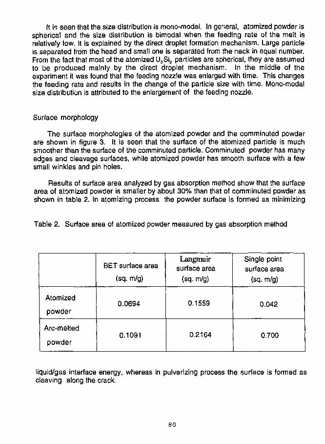
It is seen that the size distribution is mono-modal. In general, atomized powder isspherical and the size distribution is bimodal when the feeding rate of the melt isrelatively low. It is explained by the direct droplet formation mechanism. Large particleis separated from the head and small one is separated from the neck in equal number.From the fact that most of the atomized U3Si2 particles are spherical, they are assumedto be produced mainly by the direct droplet mechanism. In the middle of theexperiment it was found that the feeding nozzle was enlarged with time. This changesthe feeding rate and results in the change of the particle size with time. Mono-modalsize distribution is attributed to the enlargement of the feeding nozzle.
Surface morphology
The surface morphologies of the atomized powder and the comminuted powderare shown in figure 3. It is seen that the surface of the atomized particle is muchsmoother than the surface of the comminuted particle. Comminuted powder has manyedges and cleavage surfaces, while atomized powder has smooth surface with a fewsmall winkles and pin holes.
Results of surface area analyzed by gas absorption method show that the surfacearea of atomized powder is smaller by about 30% than that of comminuted powder asshown in table 2. In atomizing process the powder surface is formed as minimizing
Table 2. Surface area of atomized powder measured by gas absorption method
Atomized
powder
Arc-melted
powder
i
BET surface area
(sq. m/g)
0.0694
0.1091
Langmuirsurface area
(sq. m/g)
0.1559
0.2164
Single pointsurface area
(sq. m/g)
0.042
0.700
liquid/gas interface energy, whereas in pulverizing process the surface is formed ascleaving along the crack.
80
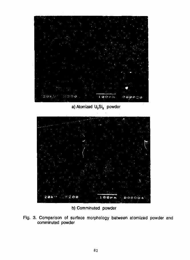
a) Atomized U3Si2 powder
b) Comminuted powder
Fig. 3. Comparison of surface morphology between atomized powder andcomminuted powder
81
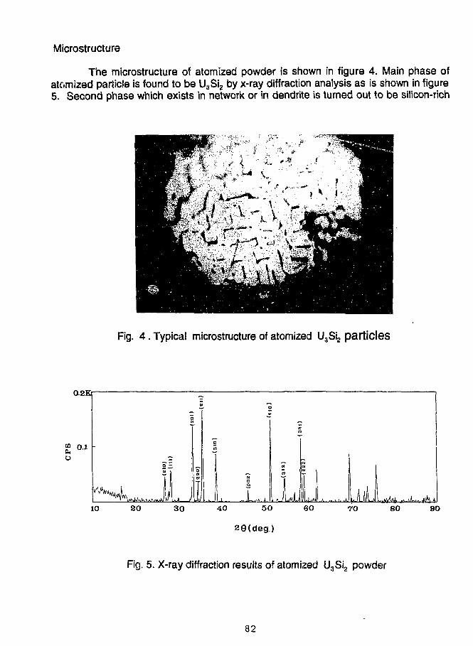
Microstructure
The microstructure of atomized powder is shown in figure 4. Main phase ofatomized particle is found to be U3Si2 by x-ray diffraction analysis as is shown in figure5. Second phase which exists in network or in dendrite is turned out to be silicon-rich
Fig. 4 . Typical microstructure of atomized U3Si2 particles
0.2Kr
26(deg.)
Fig. 5. X-ray diffraction results of atomized U3Si2 powder
82
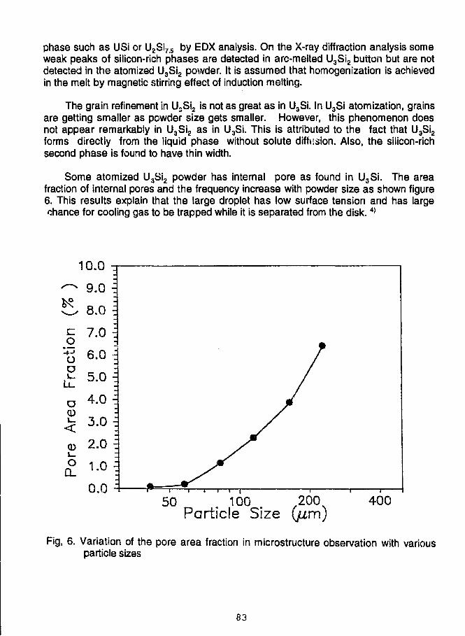
phase such as USi or U2Si75 by EDX analysis. On the X-ray diffraction analysis someweak peaks of silicon-rich phases are detected in arc-melted U3Si2 button but are notdetected in the atomized U3Si2 powder. It is assumed that homogenization is achievedin the melt by magnetic stirring effect of induction melting.
The grain refinement in U3Si2 is not as great as in U3Si. In U3Si atomization, grainsare getting smaller as powder size gets smaller. However, this phenomenon doesnot appear remarkably in U3Si2 as in U3Si. This is attributed to the fact that U3Si2forms directly from the liquid phase without solute diffusion. Also, the silicon-richsecond phase is found to have thin width.
Some atomized U3Si2 powder has internal pore as found in U3Si. The areafraction of internal pores and the frequency increase with powder size as shown figure6. This results explain that the large droplet has low surface tension and has largechance for cooling gas to be trapped while it is separated from the disk.4>
50 100 200Particle Size (p,m)
400
Fig, 6. Variation of the pore area fraction in microstructure observation with variousparticle sizes
83
CONCLUSION
A technique was developed to produce U3Si2 powder using rotating disk atomizer,following U3Si atomization last year. It is found that the atomized U3Si2 powder hasspherical shape and smooth surface as U3Si. Grain refinement is not as great as inU3Si. However, homogeneous phase is found to be formed in the resultant atomizedparticle. Some powder contains internal pores as U3Si and the frequency increaseswith particle size.
Characteristics of the atomized U3Si2 powder, i.e., spherical shape, smoothsurface and homogeneity are expected to give some improving effects on fabricationand reactor performance of the research reactor fuel.
REFERENCE
1.1. H. KuK, "Atomization of U3Si Nuclear Fuel", Proceedings of the InternationalMeeting on Reduced Enrichment for Research and Test Reactor, Rhode Island,U.S.A., September, 1990
2. C. K. Kim, "Atomization of U3Si for research reactor fuel", Proceedings of theinternational Meeting on Reduced Enrichment for Research and Test Reactor,
Jakarta, Indonesia, November, 1991
3. B. Champagne, R. Angers, " Fabrication of Powder by the Rotating ElectrodeProcess", The international Journal of Powder Metallurgy & Powder technology,16(1980)359-367
4. L L'Estrade. H. Hallen and R. Ljunggren, "Internal Porosity of Gas & AtomizedPowders", HOGANAS, Sweden
84
A NEW X-RAY INSPECTION OF FUEL PLATES
JF. POUPARD - A TISSIERCERCA
Les Berauds - BP 111426104 Romans-Sur Isere, France
ABSTRACT
A new X-Ray Inspection Machine based on directly numerizedsignals has been developed by CERCA. For U-distribution check,this machine presents specific advantages with respect to thepreviously used equipments. It also allows image processing forfurther developments.
INTRODUCTION
As the silicide fuel plates production increased at CERCA,the inspection methods have been adapted to these new products.New equipments have been developed for U-235 content in fuelcores and for ultrasonic inspection of fuel plates. As the MTRactivities increased very quickly, CERCA has defined a R&Dprogram to improve the services we offer to our customers.Within this R&D program, CERCA has developed a machine for X-Ray inspection based on image processing.
GENERAL SCOPE
The machine has to achieve the following threeinspections :
to check dimensions, geometry and positioning of themeat in the fuel plates : fluoroscopy;to detect, to locate and to measure possibleinclusions in the meat and stray particles ("remoteislands") outside the meat : X-Ray films examination;to verify the homogeneity of the uranium distributionin the meat : uranium distribution
85
The principles of the machine are as follows :
1/ the fuel plate is submitted to an X-Ray exposure;2/ the fuel plate is placed in a steady mechanical device
between the X-Ray source and the detector;3/ the detector is placed on the other side of the fuel
plate to convert the X-Ray flux transmitted throughthe fuel plate into numerical signals;
See Appendix lf for schematic principles.
All the numerical data (in grey levels) given by thedetector are transmitted to a computer to give a real-timeimage of the fuel plate. This image is processed in order togive an evaluation of :
- U density in fuel plates on a given reference surface(usually 10 x 10 mm);dimensions and locations of defects giving a contrastexceeding a given level ("black" or "white'1 spots);
- meat dimensions to be compared automatically todimensions and locations defined by thespecifications.
All the results may be stored on a mass memory system(optical numerical disk).
SCHEDULE
The schedule of development of this machine is given inAppendix 2. The equipment is installed in the MTR workshop atthe Romans plant since beginning of July 1992.
Evaluation tests have started now for U distribution andfor image processing as presented here below.
FIRST STEP : URANIUM DISTRIBUTION
Principles :
The same basic principle has been chosen for inspection.It is based on X-Ray absorption and comparison to an aluminiumstandard of an equivalent thickness. The X-Ray station works inthe same energy range . The machine issues the same reports andsame charts than the previous equipment and the machine is ableto perform the inspection with the spot size or surface definedin the specifications.
86
Basically the most important is that this equipment canpprform the inspection for uranium distribution in respect withall the existing specifications, as required under CERCAQuality Assurance procedures.
Advantages :
the inspection time per fuel plate is stronglyreduced;it is very easy to choose scanning of the wholesurface or scanning of one or two lines;the mechanics used is more modern and more precise;flexibility is increased J it is possible to chooseinspection compared to nominal value of U-density orcompared to mean value of U-density of the fuel plate;inspection may be performed on fuel plates beforecutting to size (short delay between manufacturing andinspection which permits quick feedback for processcontrol).
Results :
Comparison has been done with the results given by theprevious equipments. Both totally agree.
Of course, we are very open to cooperate with everyinterested customer.
SECOND STEP : IMAGE PROCESSING
Principles :
In fact U distribution inspection results from atreatment of numerical data given by the equipment. Those datacould also be used to give an image of the fuel plate (meat andaluminium sides and ends). This image can be used to evaluatedimensions of meat (including lack of uranium, horn,overlength) accordingly to computerized customer'sspecification. Moreover the image processing allows to detect,locate and measure inclusions on the meat and stray particlesoutside the meat. ^,
Advantages : »•*—>*/
a near real time imaging equipment allowing very quickfeedback to manufacturing process;
- no variability due to film processing or operatorinterpretation;
87
storage and archive of data on optical numerical diskeasier to handle and to store than films (speciallyfor long time storage);reliability of automatic interpretation by computersystem increased compared to human interpretation;quantified values of defects given directly by imageprocessing and used for building a data base usefulfor process improvement.
- easier surveillance inspection performed by customerswithout difficult interpretation of X-ray films.
Preliminary results :
Tests have been performed to verify that tn£ Qqulpirsent isable to conduct inspection according to the existingspecification.
Images of fuel p." tes could be presented with thedifferent types of defects.
We have the intent to go further on the definition orthis inspection, and >...•• f. course, for that, we have to cooperatewith all our customers.
CONCLUSION
A new equipment for X-Ray inspection of fuel plates hasbeen developed by CERCA. We wanted to have an equipment able tobe used on an industrial scale for U distribution test. It isplanned to use new advantages of this machine, due to itsflexibility, to perform a complete X-Ray inspection. This stepis planned in accordance with the general goals for qualitywithin the company.
To improve quality CERCA will strongly try :
to reduce times between manufacturing and inspectionoperations in order to provide quick feedback to themanufacturing process;
to give, as far as possible, numerical values and dataof defects, in order to provide a complete data baseon process capability.
The new equipment was designed in respect to these generalgoals.
88
Now, to perform a complete X-Ray inspection with thismachine we have to follow the very fast evolution of relatednew techniques.
In order to satisfy really the needs and requirements ofour customers an additional work has to be done in cooperationwith them. Such points as recording means, documentation ofresults, archive methods have to be defined with the customers.
This is the challenge for the coming years.
89
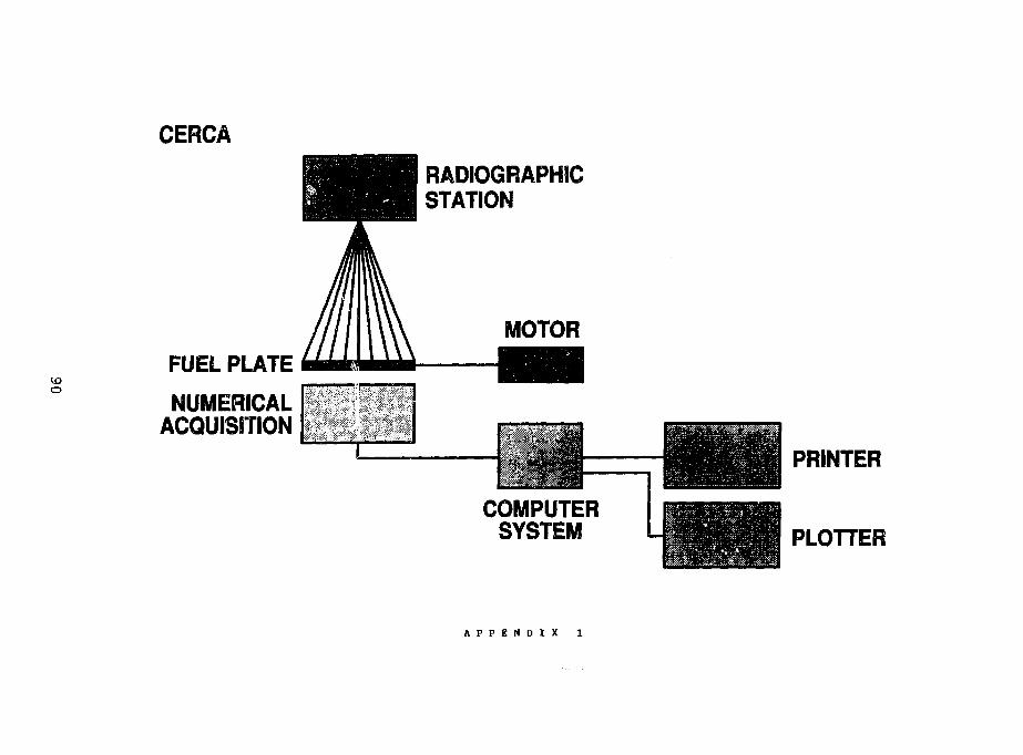
CERCA
RADI0GRAPH1CSTATION
IDO
FUEL PLATE
NUMERICALACQUISITION
1-—1MOTOR
HH
•m
I
COMPUTERSYSTEM
PRINTER
PLOTTER
A P P E N D I X 1
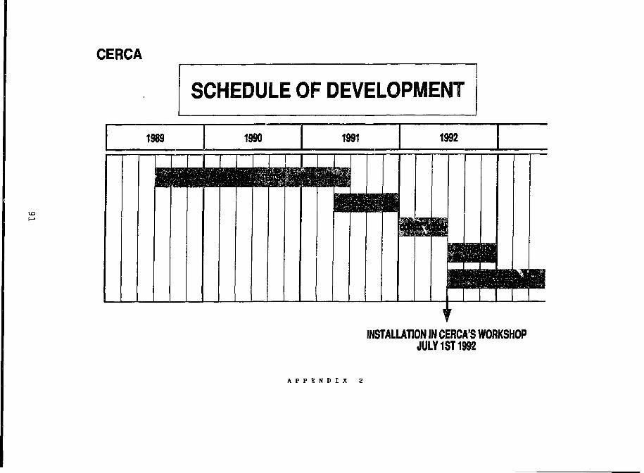
CERCA
SCHEDULE OF DEVELOPMENT
INSTALLATION IN CERCA'S WORKSHOPJULY 1ST 1992
A P P E N D I X 2
CHARACTERIZATION OF COMMERCIALLY PURE ALUMINUM POWDERFOR RESEARCH REACTOR FUEL PLATES*
V. D. DownsBabcock S WilcoxLynchburg, VA USA
and
T. C. WiencekArgonne National Laboratory
Argonne, IL USA
ABSTRACT
Aluminum powder is used as the matrix material in theproduction of uranium aluminide, oxide, and silicide dispersionfuel plates for research and test reactors. Variability in thecharacteristics of the aluminum powder, such as moist-re contentand particle-size distribution, influences blending and compactingof the aluminum/fuel powder.
A detailed study was performed to characterize the physicalproperties of three aluminum powder lots. An angle-of-shear testwas devised to characterize the cohesiveness of the aluminumpowder. Flow-rate measurements, apparent density determination,subsieve analysis, surface area measurements, and scanningelectron microscopy were also used in the study.
It was found that because of the various types of commerciallyavailable powders, proper specification of powder variables willensure the receipt of consistent raw materials. Improved controlof the initial powder will reduce the variability of fuel-plateproduction and will improve overall plate reproducibility. It isrecommended that a standard specification be written for thealuminum powder and silicide fuel.
1 INTRODUCTION
The success of fuel-plate production depends to a great extent on thecharacterization and control of the initial raw materials. Reptoducibility ofthe fabrication processes is best achieved by the use of consistent rawmaterials. Often the problem is not so much how to control the raw material,but rather knowing what to control. Powders have many characteristics, someinterrelated, that must be considered. Among these are shape, surface area-particle structure, composition, bulk density, apparent density, size
*Work supported by the U.S. Department of Energy, Office of InternationalAffairs and Energy Emergencies, under Contract No. W-31-109-ENG-38
92
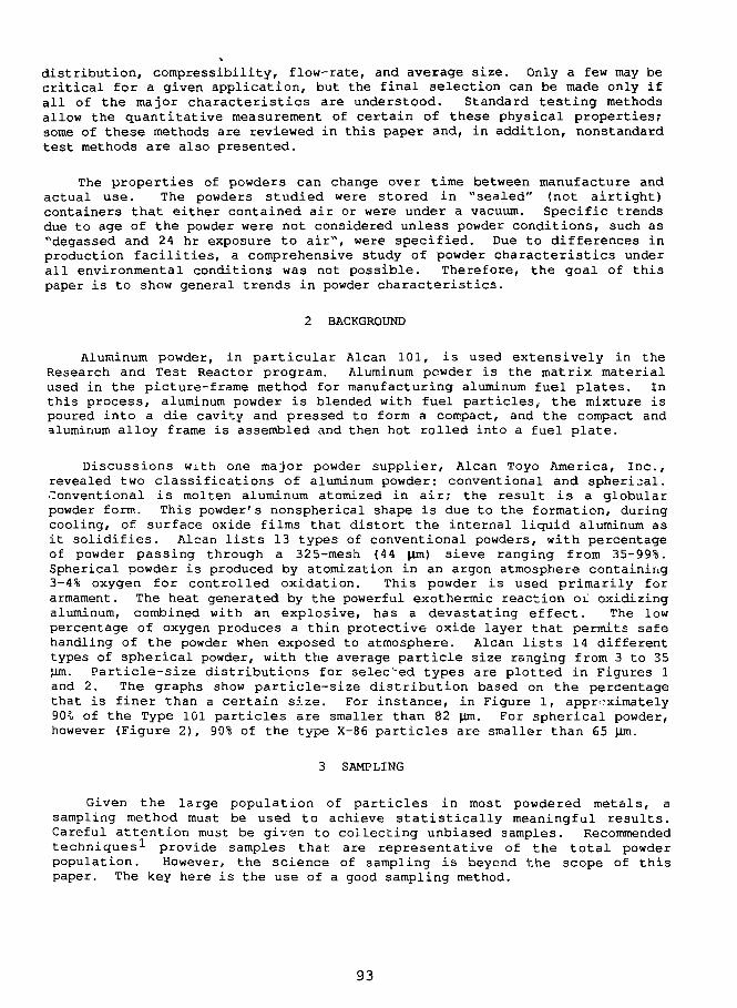
distribution, compressibility, flow-rate, and average size. Only a few may becritical for a given application, but the final selection can be made only ifall of the major characteristics are understood. Standard testing methodsallow the quantitative measurement of certain of these physical properties;some of these methods are reviewed in this paper and, in addition, nonstandardtest methods are also presented.
The properties of powders can change over time between manufacture andactual use. The powders studied were stored in "sealed" (not airtight)containers that either contained air or were under a vacuum. Specific trendsdue to age of the powder were not considered unless powder conditions, such as"degassed and 24 hr exposure to air", were specified. Due to differences inproduction facilities, a comprehensive study of powder characteristics underall environmental conditions was not possible. Therefore, the goal of thispaper is to show general trends in powder characteristics.
2 BACKGROUND
Aluminum powder, in particular Alcan 101, is used extensively in theResearch and Test Reactor program. Aluminum powder is the matrix materialused in the picture-frame method for manufacturing aluminum fuel plates. Inthis process, aluminum powder is blended with fuel particles,, the mixture ispoured into a die cavity and pressed to form a compact, and the compact andaluminum alloy frame is assembled and then hot rolled into a fuel plate.
Discussions with one major powder supplier, Alcan Toyo America, Inc.,revealed two classifications of aluminum powder: conventional and spherical.Conventional is molten aluminum atomized in air; the result is a globularpowder form. This powder's nonspherical shape is due to the formation, duringcooling, of surface oxide films that distort the internal liquid aluminum asit solidifies. Alcan lists 13 types of conventional powders, with percentageof powder passing through a 325-mesh (44 ]im) sieve ranging from 35-99%.Spherical powder is produced by atomization in an argon atmosphere containing3-4% oxygen for controlled oxidation. This powder is used primarily forarmament. The heat generated by the powerful exothermic reaction oi oxidizingaluminum, combined with an explosive, has a devastating effect. The lowpercentage of oxygen produces a thin protective oxide layer that permits safehandling of the powder when exposed to atmosphere. Alcan lists 14 differenttypes of spherical powder, with the average particle size ranging from 3 to 35Jim. Particle-size distributions for selected types are plotted in Figures 1and 2. The graphs show particle-size distribution based on the percentagethat is finer than a certain size. For instance, in Figure 1, approximately90% of the Type 101 particles are smaller than 82 |im. For spherical powder,however (Figure 2), 90% of the type X-86 particles are smaller than 65 |Xm.
3 SAMPLING
Given the large population of particles in most powdered metals, asampling method must be used to achieve statistically meaningful results.Careful attention must be given to collecting unbiased samples. Recommendedtechniques^ provide samples that are representative of the total powderpopulation. However, the science of sampling is beyond the scope of thispaper. The key here is the use of a good sampling method.
93
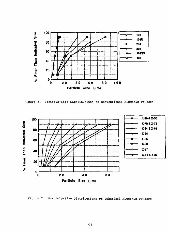
N
CO
coo
a
flj
100
80
60
40
20
r///f// r/*
/
U/
//s
/<^
...mnnT
/ "JW
20 40 60 80
Particle Size (|xm)
1 0 0
Figure 1. Particle-Size Distributions of Conventional Aluminum Powders
100
CO
• oas
cati
•occCO
£
80
60
40
20
20 40
Particle Size (\im)
6 0
•o X-30 & X-50
•+ X-70 & X-71
- • X-64 & X-65
- • X-86
- • — • X-85
-C—• X-80
-* X-67
- * X-81 & X-82
Figure 2. Particle-Size Distributions of Spherical Aluminum Powders
94
4 CHARACTERISTICS OF STANDARD POWDERED METAL
4.1 Analysis of Powder Size by Sieve Tests
Particle-size analysis^ is a common, rapid, and easy test for powderedmetals. Data are usually generated by sieving the material through a seriesof screens. Results are given by the weight percentage of material above acertain diameter that will not pass through the screen. The screens rangefrom large >0.3 cm (6-rnesh) to the smallest commonly used standard sieve sizeof 37 \im (400-mesh) .
The majority of the aluminum powder used for fuel plate production issmaller than 44 |im. A common powder is Alcan Type 101. This powder has arange of 75-85 wt. % <44 Jim particles. Thus, a common specification is therequirement of a minimum amount of <44 Urn-size powder. However, this can be amisleading specification because sieve-test results are greatly influenced bythe time of sieving and the intensity of vibration. Sieve tests are onlyvalid if the forces that tend to agglomerate powders are overcome by themechanical action of the sieve shaker. Forces that bind particles togetherresult from (a) friction due to the physical shape of particles, (b) Van derWaals forces acting on the powder itself, and (c) adsorbed surface-watermolecules.
Small particles are more influenced by Van der Waals forces than arelarger particles due to the smaller mass per surface area. This force isfurther enhanced by water molecules attached to small particles. To preventthese forces from influencing powder-particle-size determination, wet sievingis recommended. A low-viscosity liquid, (e.g., acetone) can be used as acarrier vehicle to counteract the forces acting on the dry powder. Thisgeneral cest is very useful for describing aluminum powder, but should not bethe sole specification for production powder.
Three lots of aluminum powder were extensively studied in this review.Table 1 summarizes analytical results of the as-certified Alcan powder.
Powders from the three different batches of as-received aluminum powderwere individually blended and then dry sieved at Argonne National Laboratory(ANL) for comparison with the manufacturer's data. The results are given inFigure 3 for the coarse (>44 \im) particles. The fines (<44 (im) ) were 78, 84,and 77% for Lots 10003, 1770 and CO-713, respectively. The data agree wellwith those in Table 1. Two characteristics are of major concern incontrolling the feedstock powder. First, a significant amount of powder ispresent in the 53-125 \lm sizes. Control of this powder distribution may benecessary to improve fuel core reproducibility. Second, the range ofallowable <44 |im powder for Alcan 101 aluminum is 75-85%. Although all thre.lots fall within this range, the differences between lots are significant a 'may affect the final powder properties. Overall, Figure 3 shows signific? itdifferences in powder-size distributions. These differences may lead ^ovariance in final fuel-plate homogeneity.
95
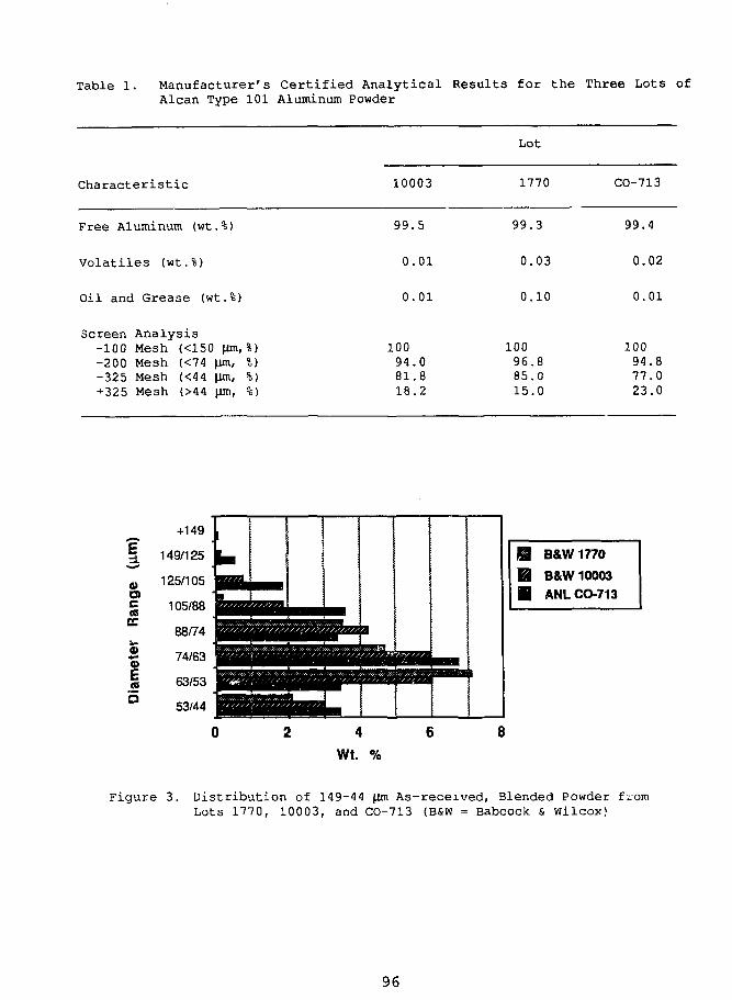
Table 1. Manufacturer's Certified Analytical Results for the Three Lots ofAlcan Type 101 Aluminum Powder
Characteristic
Free Aluminum (wt.%)
Volatiles (wt.%)
Oil and Grease (wt.%)
Screen Analys is-100 Mesh (<150 (im, %)-200 Mesh (<74 \im, %)-325 Mesh (<44 ^m, %)+325 Mesh (>44 \)m, %)
10003
99 .
0.
0.
10094 .8 1 .1 8 .
5
01
01
082
Lot
1770 CO-713
99.
0 .
0 .
10096.85.15.
3
03
10
800
99 .4
0.02
0.01
10094.877.023.0
0)CDcCO
EC
0>•**0)
.2a
+149 L
149/125 j ^
125/105 B Q |
105/88 & m
88/74 jgggIS jSRBBJss/4/B3 mmmatBuaa/aSSSES63/53 BQZgBBBBBBa
53/44 Bgjg[[j{BflsBiFpmn- •
B&W 1770
B&W 10003
ANL CO-713
4
Wt. %
Figure 3. Distribution of 149-44 |im As-received, Blended Powder fromLots 1770, 10003, and CO-713 (B&W = Babcock & Wilcox)
96
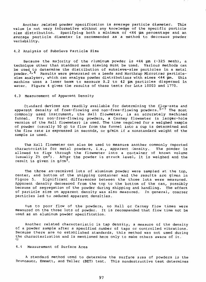
Another related powder specification is average particle diameter. Thisvalue is not very informative without any knowledge of the specific particlesize distribution. Specifying both a minimum of <44 (im percentage and anaverage particle diameter is recommended as a method to decrease powdervariability.
4.2 Analysis of Subsieva Particle Size
Because the majority of the aluminum powder is <44 \m (-325 mesh), atechnique other than standard mesh sieving must be used. Various methods canbe used to determine the distribution of subsieve-size particles in a metalpowder.3»4 Results were generated on a Leeds and Northrup Microtrac particle-size analyzer, which can analyze powder distributions with sizes <44 |im. Thismachine uses a laser beam to measure 0.2 to 42 Jim particles dispersed inwater. Figure 4 gives the results of these tests for Lots 10003 and 1770.
4.3 Measurement of Apparent Density
Standard devices are readily available for determining the flow-rate andapparent density of free-flowing and non-free-flowing powders.^"7 The mostcommonly used instrument, the Hall flowmeter, is an accurately machinedfunnel. For non-free-flowing powders, a Carney flowmeter (a larger-holeversion of the Hall flowmeter) is used. The time required for a weighed sampleof powder (usually 50 g) to flow from the funnel into a cup is determined andthe flow rate is expressed in seconds, or g/min if a nonstandard weight of thesample is used.
The Hall flowmeter can also be used to measure another commonly reportedcharacteristic for metal powders, i.e., apparent density. The powder isallowed to flow through the flowmeter into a container of known volume(usually 25 cm^) . After the powder is struck level, it is weighed and theresult is given in g/crn̂ .
The three as-received lots of aluminum powder were sampled at the top,center, and bottom of the shipping container and the results are given inFigure 5. Significant differences between the three lots were measured.Apparent density decreased from the top to the bottom of the can, possiblybecause of segregation of the powder during shipping and handling. The effectof particle size on apparent density was also measured. In general, coarserparticles led to reduced apparent densities.
Due to poor flow of the powders, no Hall or Carney flow times weremeasured on the three lots of powder. It is recommended that flow time not beused as an aluminum powder specification.
Another related characteristic is tap density, a measure of the densityof a powder sample after a specified number of taps or controlled vibrations.Because there are no established standards, this method was not used duringthe characterization and is mentioned here only to make others aware of it.
4.4 Measurement of Surface Area
A standard method used to determine the surface area of powders is theBrunnauer, Emmett, and Teller (BET) test. This nondestructive test determines
97
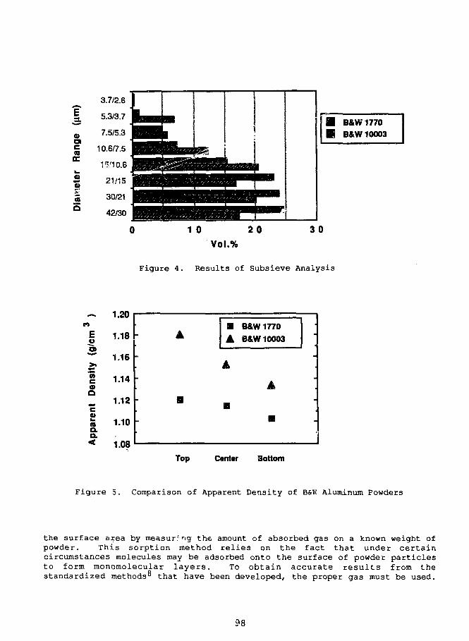
IoCO
ccfl)
3.7/2.6 I |
5.3/3.7 R a m m7.5/5.3 H B L
10.6/7.5 H H B M R B B M
i5,'io.6 EBHII^^MBPBHLa«ggrt2i/i5 J||^|yippB6BMBlBBWPwl
30/21 ^^BHIHIvR^B^^^^42/30 BBBBBWH
BSSSS5SS Ml I
B&W1770B&W 10003
1 0 20 30
Yol.%
Figure 4. Results of Subsieve Analysis
nE
2
it D
ensi
tip
aren
<
1.20
1.18
1.16
1.14
1.12
1.10
1.08
•
• B&W 1770
A B&W 10003
•
•
Top Canter Bottom
Figure 5. Comparison of Apparent Density of B&K Aluminum Powders
the surface area by measuring the amount of absorbed gas on a known weight ofpowder. This sorption method relies on the fact that under certaincircumstances molecules may be adsorbed onto the surface of powder particlesto form monomolecular layers. To obtain accurate results from thestandardized methods'* that have been developed, the proper gas must be used.
98
Surface areas in the range of 0.02 to 5.0 m2/g area (111-0.44 |im averageparticle size) are measured with krypton gas as the adsorbate. In the rangefrom 3 to 100 m^/g (0.74-0.02 |im average particle size), nitrogen gas is used.
For surface-area measurements, a Micromeritics Instrument CorporationFlowSorb II 2300 was available. However, due to scheduling and equipmentproblems only limited measurements were taken. Because of the preliminarynature of the information, the results are not included in this report.
5 NONSTANDARD TESTS FOR POWDER METAL CHARACTERISTICS
5.1 Angle of Shear
Cohesive strength is a critical parameter in predicting blending and die-loading characteristics of powders. Both blending and die loading directly,affect the homogeneity of the final fuel core. The angle of shear (which issimilar to angle of repose) determines the relative cohesive strength of thealuminum powder. No simple and inexpensive standardized test was found thatcould provide the necessary information. A simple test was developed thatuses a bottom-sieve testing catch pan. A fine-grit abrasive paper was placedin the bottom of the pan to ensure that the relative shear forces within thepowder will be determined, rather than sliding friction between powder andpan. Powder was shaken onto the abrasive paper to form a rectangular section.One edge of the pan was placed against a reference mark, while the oppositeedge was slowly tilted upward alongside a vertical ruler. When the powdermoved, trigonometric principles were used to calculate the angle of shear.Results of testing at ANL and BSW are shown in Table 2.
Annealed powder was maintained in vacuum storage until needed. The testsat ANL were performed in the winter with typically 25-35% relative humidity.Testing at BSW took place during the summer in a humidity-controlled room withless than 64% relative humidity. Humidity was found to be an important factorin determining angle of shear. The powder adsorbed moisture immediately uponexposure to air. Moisture adsorption continued to affect the angle of shearuntil, in the case of Lot 10003, the pan was raised to the maximum possibleangle vertically and the powder remained intact as a pile. It has not beendetermined why one powder lot was affected more by moisture than the others.
5.2 Surface Morphology
Three center samples were examined by scanning electron microscopy (SEM).Two different size ranges, >63 \lm (+230 mesh) and <44 \lm (-325 mesh), fromeach lot were studied. No significant differences in shape or surface werenoted after visual inspection at magnifications of 75 to 800X for all sixsamples. All three lots were granular or complex-nodular (not spherical),which is characteristic of air-atomized powder. A typical SEM photograph ofthe aluminum powder is shown in Figure 6. For production-powder analysis, animaging program such as Image 1.44 from the USA National Institutes for Healthcould be used to analyze for the average particle size and distribution.
99
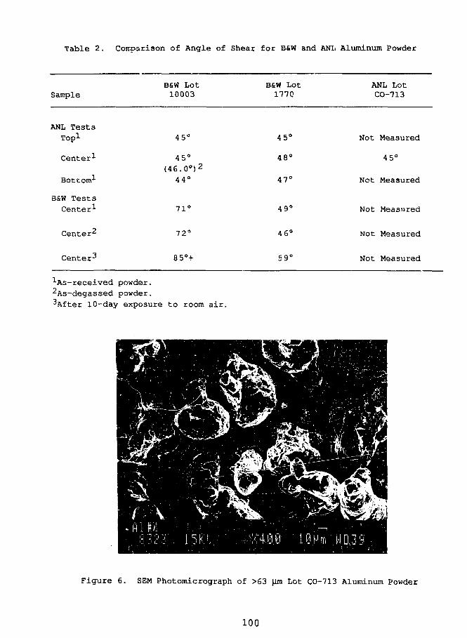
Table 2. Comparison of Angle of Shear for B&W and ANL Aluminum Powder
SampleBSW Lot10003
BSW Lot1770
ANL LotCO-713
ANL Tests
Top1
Center1
Bottom1
B&W TestsCenter1
Center2
Center3
45*
45°(46 . 0 ° ) 2
44°
71 C
72C
85°-
45°
48°
47°
49°
46°
59C
Not Measured
45°
Not Measured
Not Measured
Not Measured
Not Measured
•'•As-received powder.
2As-degassed powder.
10-day exposure to room air.
Figure 6. SEM Photomicrograph of >63 Jim Lot CO-713 Aluminum Powder
100
6 SUMMARY AND RECOMMENDATIONS
A precise aluminum powder specification is a key step in consistentlymanufacturing acceptable powder-metallurgy-type fuel plates. ANL and B&W areworking jointly (in conjunction with Oak Ridge National Laboratory and EG&GIdaho National Engineering Laboratory) to establish a standard specificationfor aluminum powder. It may be beneficial to the Research and Test ReactorFuel Elements (RTRFE) ccircnunity to establish an international standard for:powder type (atomized, flake, or granule), particle shape (globular,spherical, acicular, irregular, etc.), range limits for average particle size,particle size distribution, and surface area. An international standard wouldensure uniformity in the materials U3ed to manufacture fuel plates.
Receipt inspection and testing of aluminum powder lots are necessarybefore releasing the powder tc the fabrication process. Because the originalpowder costs make up only a iow percentage of the final finished fuel-platecost, any lot not meeting the desired specifications should be rejected. Inaddition, a standard specification such as that for plutonium dioxide powder^may also need to be developed for the fuel powder.
REFERENCES1. Standard Test Methods of Sampling Finished Lots of Metal Powders,
American Society for Testing and Materials, Standard No. B 215,Vol. 02.05, 1982.
2. Standard Test Method for Sieve Analysis of Granular Metal Powders,American Society for Testing and Materials, Standard No. B 214,Vol. 02.05, 1986.
3. Standard Test Method for Average Particle Size of Powders of RefractoryMetals and Their Compounds By the Fisher Sub-Sieve Sizer, AmericanSociety for Testing and Materials, Standard No. B 330, Vol. 02.05, 1982.
4. Standard Test Method for Particle Size Distribution of Refractory Metal-Type Powders by Turbidimetry, American Society for Testing and Materials,Standard No. B 430, Vol. 02.05, 1984.
5. Standard Test Method for Apparent Density of Free-Flowing Metal Powders,American Society for Testing and Materials, Standard No. B 212,Vol. 02.05, 1982.
6. Standard Test Method for Flow Rate of Metal Powders, American Society forTesting and Materials, Standard Number B 213, Volume 02.05, 1990.
7. Standard Test Method for Apparent Density of Non-Flowing Metal Powders,American Society for Testing and Materials, Standard No. B 417,Vol. 02.05, 1989.
8 Standard Methods for Chemical, Mass Spectrometric and SpectrochemicalAnalysis of Nuclear-Grade Uranium Dioxide Powders and Pellets, AmericanSociety for Testing and Materials, Standard No. C 696, Vol. 12.01, 1980.
9. Standard Specification for Nuclear-Grade Plutonium Dioxide Powder,Sinterable, American Society for Testing and Materials, StandardNo. C 757, Vol. 12.01, 1983.
101
S E S S I O N III
September 28, 1992
LICENSING ASPECTS
Chairman:
H. Buchholz(Hahn-Meitner— Instltut, Germany)
103
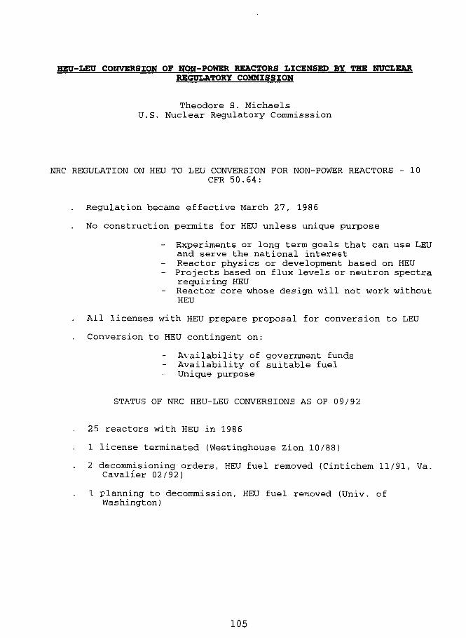
HEU-LEU CONVERSION OF NON-POWER REACTORS LICENSED BY THE NUCLEARREGULATORY COMMISSION
Theodore S. MichaelsU.S. Nuclear Regulatory Commisssion
NRC REGULATION ON HEU TO LEU CONVERSION FOR NON-POWER REACTORS - 10CFR 50.64:
Regulation became effective March 27, 1986
No construction permits for HEU unless unique purpose
Experiments or long term goals that can use LEUand serve the national interestReactor physics or development based on HEU
- Projects based on flux levels or neutron spectrarequiring HEUReactor core whose design will not work withoutHEU
All licenses with HEU prepare proposal for conversion to LEU
Conversion to HEU contingent on:
Availability of government fundsAvailability of suitable fuelUnique purpose
STATUS OF NRC HEU-LEU CONVERSIONS AS OF 09/92
25 reactors with HEU in 1986
1 license terminated (Westinghouse Zion 10/88)
2 decommisioning orders, HEU fuel removed (Cintichem 11/91, Va.Cavalier 02/92)
1 planning to decommission, HEU fuel removed (Univ. ofWashington)
105
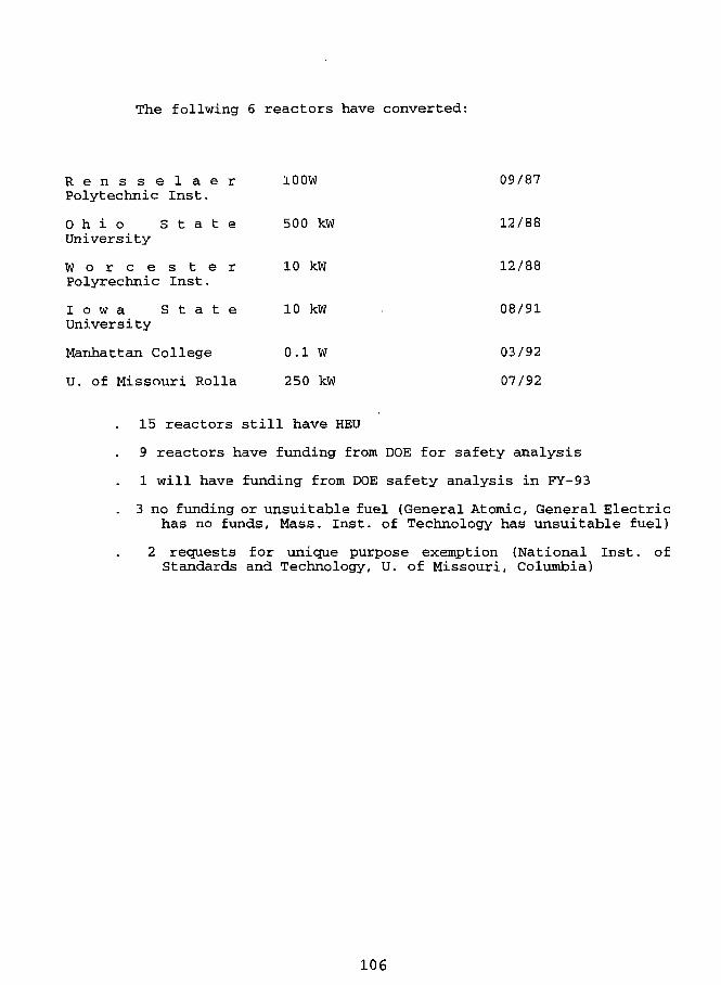
The follwing 6 reactors have converted:
R e n s s e l a e r 100W 09/87Polytechnic Inst.
O h i o S t a t e 500 kW 12/88University
W o r c e s t e r 10 kW 12/88Polyrechnic Inst.
I o w a S t a t e 10 kW 08/91
University
Manhattan College 0.1 W 03/92
U. of Missouri Rolla 250 kW 07/92
15 reactors still have HEU
9 reactors have funding from DOE for safety analysis
1 will have funding from DOE safety analysis in FY-93
. 3 no funding or unsuitable fuel (General Atomic, General Electrichas no funds. Mass. Inst. of Technology has unsuitable fuel)
2 requests for unique purpose exemption (National Inst. ofStandards and Technology, U. of Missouri, Columbia)
106
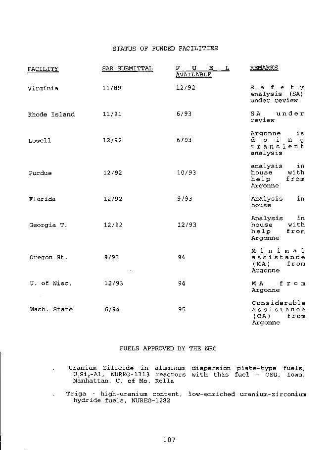
STATUS OF FUNDED FACILITIES
FACILITY
Virginia
SAR SUBMITTAL
11/89
U EAVAILABLE
12/92
REMARKS
S a f e t yanalysis (SA)under review
Rhode Island 11/91 6/93 S A u n d e rreview
Lowell
Purdue
Florida
Georgia T.
Oregon St.
U. of Wise.
Wash. State
12/92
12/92
12/92
12/92
9/93
12/93
6/94
6/93
10/93
9/93
L2/93
94
94
95
Argonne isd o i n gt r a n s i e n tanalysis
analysis inhouse withh e l p f romArgonne
Analysishouse
i n
Analysis inhouse withh e l p fromArgonne
M i n i m a la s s i s t a n c e(MA) fromArgonne
MA f r oArgonne
m
Considerablea s s i s t a n c e(CA) fromArgonne
FUELS APPROVED BY THE NRC
Uranium Silicide in aluminum dispersion plate-type fuels,U3Si2-Al, NUREG-1313 reactors with this fuel - OSU, Iowa,Manhattan, U. of Mo. Rolla
Triga - high-uranium content, low-enriched uranium-zirconiumhydride fuels, NUREG-1282
107
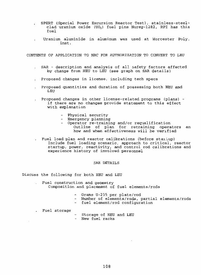
SPERT (Special Power Excursion Reactor Test), stainless-steel-clad uranium oxide (U02) fuel pins Nureg-1282, RPI has thisfuel
Uranium aluminide in aluminum was used at Worcester Poly.Inst.
CONTENTS OF APPLICATION TO NRC FOR AUTHORIZATION TO CONVERT TO LEU
SAR - description and analysis of all safety factors affectedby change from HEU to LEU (see graph on SAR details)
Proposed changes in license, including tech specs
Proposed quantities and duration of possessing both HEU andLEU
Proposed changes in other license-related programs (plans) -if there are no changes provide statement to this effectwith explanation
Physical securityEmergency planningOperator re-training and/or requalification
Outline of plan for retraining operators anhow and when effectiveness will be verified
Fuel load plan and reactor calibrations (before stay.Lup)Include fuel loading scenario, approach to critical, reactorstartup, power, reactivity, and control rod calibrations andexperience history of involved personnel
SAR DETAILS
Discuss the following for both HEU and LEU
Fuel construction and geometryComposition and placement of fuel elements/rods
Grams U-235 per plate/rodNumber of elements/rods, partial elements/rodsfuel element/rod configuration
Fuel storage- Storage of HEU and LEU
New fuel racks
108
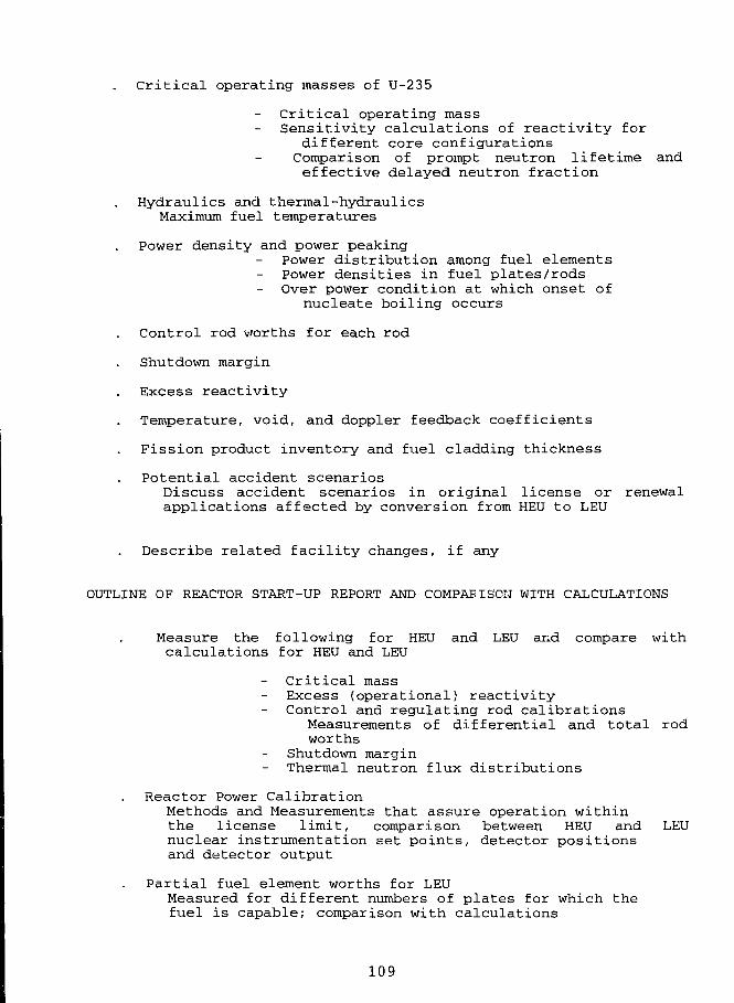
Critical operating masses of U-235
Critical operating massSensitivity calculations of reactivity for
different core configurationsComparison of prompt neutron lifetime andeffective delayed neutron fraction
Hydraulics and thermal-hydraulicsMaximum fuel temperatures
Power density and power peakingPower distribution among fuel elementsPower densities in fuel plates/rodsOver power condition at which onset of
nucleate boiling occurs
Control rod worths for each rod
Shutdown margin
Excess reactivity
Temperature, void, and doppler feedback coefficients
Fission product inventory and fuel cladding thickness
Potential accident scenariosDiscuss accident scenarios in original license or renewalapplications affected by conversion from HEU to LEU
Describe related facility changes, if any
OUTLINE OF REACTOR START-UP REPORT AND COMPARISON WITH CALCULATIONS
Measure the following for HEU and LEU and compare withcalculations for HEU and LEU
Critical massExcess (operational) reactivityControl and regulating rod calibrations
Measurements of differential and total rodworths
Shutdown marginThermal neutron flux distributions
Reactor Power CalibrationMethods and Measurements that assure operation withinthe license limit, comparison between HEU and LEUnuclear instrumentation set points, detector positionsand detector output
Partial fuel element worths for LEUMeasured for different numbers of plates for which thefuel is capable; comparison with calculations
109
Discuss how compliance with void and temperature coefficientvalues in tech specs is to be assured. Compare with anycalcu.' -.ions
Explain any significant differences in the values previouslymeasured or calculated which have an impact on both thenormal operation and potential accidents with the reactor
Measurements made during initial loading of the LEU fuel,presenting subcritical multiplication measurements,predictions of multiplication for next fuel additions, andprediction and verification of final criticality conditions
110
S E S S I O N IV
September 28, 1992
REACTORS DURING AND AFTER CONVERSION TO LEU
Chairman:
.(. Futamura(JAERI, Japan)
111
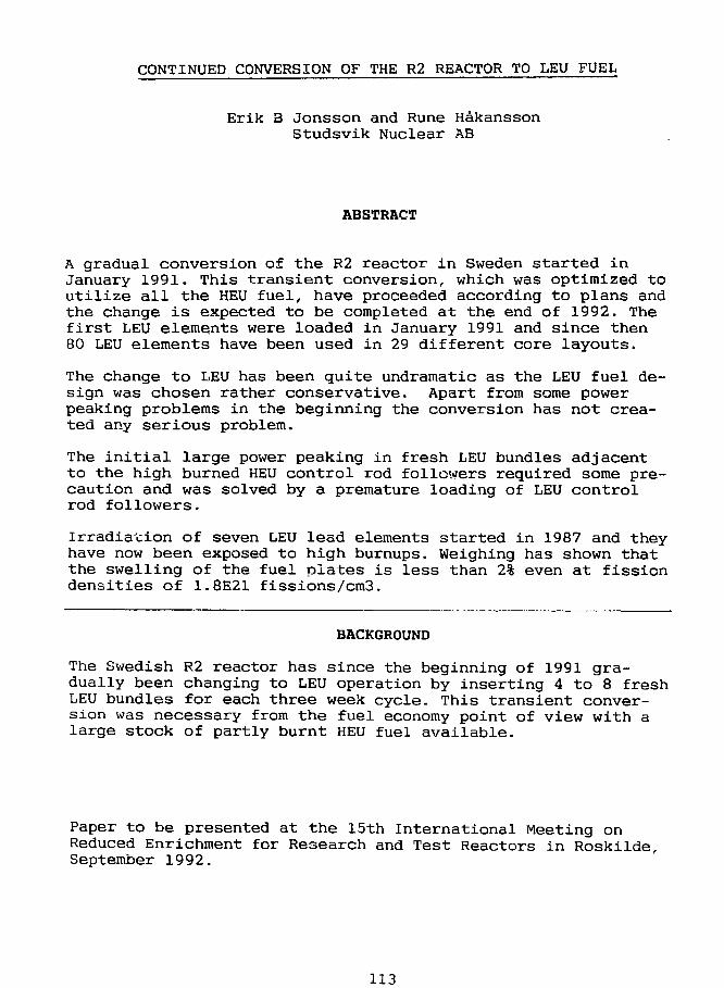
CONTINUED CONVERSION OF THE R2 REACTOR TO LEU FUEL
Erik 3 Jonsson and Rune HakanssonStudsv ik Nuclear AB
ABSTRACT
A gradual conversion of the R2 reactor in Sweden started inJanuary 1991. This transient conversion, which was optimized toutilize all the HEU fuel, have proceeded according to plans andthe change is expected to be completed at the end of 1992. Thefirst LEU elements were loaded in January 1991 and since then80 LEU elements have been used in 29 different core layouts.
The change to LEU has been quite undramatic as the LEU fuel de-sign was chosen rather conservative. Apart from some powerpeaking problems in the beginning the conversion has not crea-ted any serious problem.
The initial large power peaking in fresh LEU bundles adjacentto the high burned HEU control rod followers required some pre-caution and was solved by a premature loading of LEU controlrod followers.
Irradiation of seven LEU lead elements started in 1987 and theyhave now been exposed to high burnups. Weighing has shown thatthe swelling of the fuel plates is less than 2% even at fissiondensities of 1.8E21 fissions/cm3.
BACKGROUND
The Swedish R2 reactor has since the beginning of 1991 gra-dually been changing to LEU operation by inserting 4 to 8 freshLEU bundles for each three week cycle. This transient conver-sion was necessary from the fuel economy point of view with alarge stock of partly burnt HEU fuel available.
Paper to be presented at the 15th International Meeting onReduced Enrichment for Research and Test Reactors in Roskilde,September 1992.
113
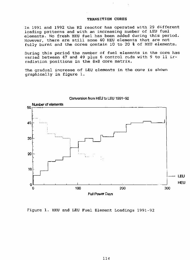
TRANSITION CORES
In 1991 and 1992 the R2 reactor has operated with 29 differentloading patterns and with an increasing number of LEU fuelelements. No fresh HEU fuel has been added during this period.However, there are still some 40 HEU elements that are notfully burnt and the cores contain 10 to 20 % of HEU elements-
During this period the number of fuel elements in the core hasvaried between 47 and 49 plus 6 control rods with 9 to 11 ir-radiation positions in the 8x8 core matrix.
The gradual increase of LEU elements in the core is showngraphically in figure 1.
Conversion from HEU to LEU 1991-92
Number of elements
100 200Full Power Days
300
Figure 1. HEU and LEU Fuel Element Loadings 1991-92
114
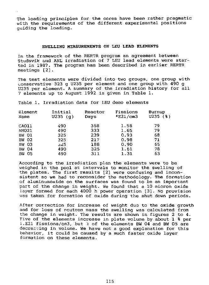
The loading principles for the cores have been rather pragmaticwith the requirements of the different experimental positionsguiding the loading.
SWELLING MEASUREMENTS ON LEU LEAD ELEMENTS
In the framework of the RERTR program an agreement betweenStudsvik and ANL irradiation of 7 LEU lead elements were star-ted in 1987. The program has been described in earlier RERTRmeetings [2].
The test elements were divided into two groups, one group withconservative 323 g U235 per element and one group with 490 gU235 per element. A summary of the irradiation history for all7 elements up to August 1992 is given in Table 1.
Table 1.
ElementName
CA011NM021BW 01BW 02BW 03BW 04BW 05
Irradiation data for LEU
InitialU235 (g)
490490325325o25490490
ReactorDays
358333239217188325311
demo elements
Fissions*E21/cm3
1.581.650.930.980.901.611.31
BurnupU235 (%)
79796871657863
According to the irradiation plan the elements were to beweighed in the pool at intervals to monitor the swelling ofthe plates. The first results [2] were confusing and incon-sistent so we had to reconsider the methodology. The formationof aluminumoxide on the surfaces was found to be an importantpart of the change in weight. We found that a 10 micron oxidelayer formed for each 4000 h power operation [3]. No provisionwas taken for formation of oxide during the shut down periods.
After correction for increase of weight due to the oxide growthand for loss of neutron mass the swelling was calculated fromthe change in weight. The results are shown in figures 2 to 4.Five of the elements increase in plate volume by about 1 % per1.E21 fissions/cm3, but "i of the elements EW 04 and BW 05 aredecreasing in volume. We have not a good explanation for thisbehavior, it could be caused by a much faster oxide layerformation on these elements.
115
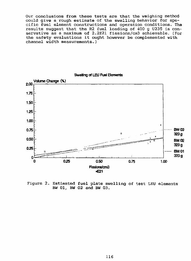
Our conclusions from these tests are that the weighing methodcould give a rough estimate of the swelling behavior for spe-cific fuel element constructions and operation conditions. Theresults suggest that the R2 fuel loading of 400 g U235 is con-servative as a maximum of 2.2E21 fissions/cm3 achievable. (Forthe safety evaluations it ought however be complemented withchannel width measurements.)
SweBing of LEU Fuei Elements
2.00Volume Change (%)
0.25 0.50Rssions/cm3
•E21
0.75 1.00
Figure 2. Estimated fuel plate swelling of test LEU elementsBW 01, BW 02 and BW 03.
116
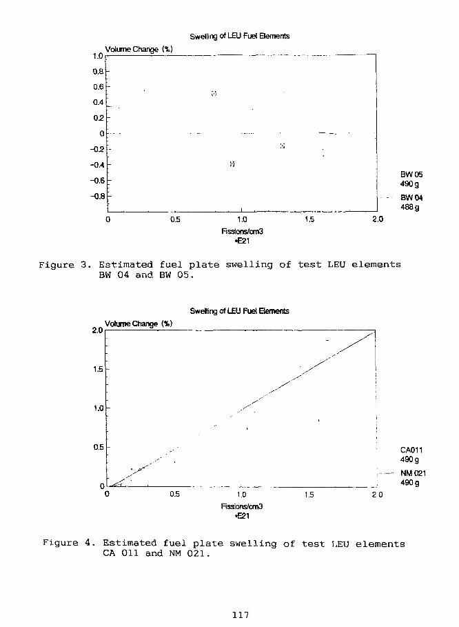
Swelling of LEU Fuel Elements
Volume Change (%)
BW05490g
BW04488g
Figure 3. Estimated fuel plate swelling of test LEU elementsBW 04 and BW 05.
Swelling of LEU Fuel Bements
2.0
1.5
1.0
0.5
Volume Change (%)
0.5 1.0
Fissions/cm3•E21
1.5
CA011490 g
NM021490 g
2.0
Figure 4. Estimated fuel plate swelling of test LEU elementsCA 011 and NM 021.
117
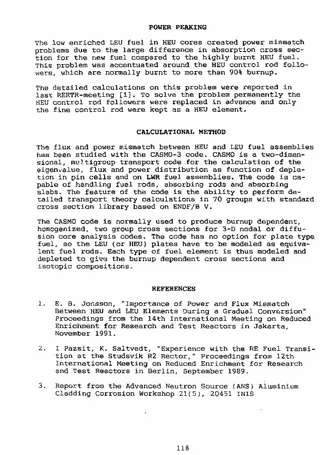
POWER PEAKING
The low enriched LEU fuel in HEU cores created power mismatchproblems due to the large difference in absorption cross sec-tion for the new fuel compared to the highly burnt HEU fuel.This problem was accentuated around the HEU control rod follo-wers, which are normally burnt to more than 90% burnup.
The detailed calculations on this problem were reported inlast RERTR-meeting [1]. To solve the problem permanently theHEU control rod followers were replaced in advance and onlythe fine control rod were kept as a HEU element.
CALCULATIONAL METHOD
The flux and power mismatch between HEU and LEU fuel assemblieshas been studied with the CASM0-3 code. CASMO is a two-dimen-sional, multigroup transport code for the calculation of theeigenvalue, flux and power distribution as function of deple-tion in pin cells and on LWR fuel assemblies. The code is ca-pable of handling fuel rods, absorbing rods and absorbingslabs. The feature of the code is the ability to perform de-tailed transport theory calculations in 70 groups with standardcross section library based on ENDF/B V.
The CASMO code is normally used to produce burnup dependent,homogenized, two group cross sections for 3-D nodal or diffu-sion core analysis codes. The code has no option for plate typefuel, so the LEU (or HEU) plates have to be modeled as equiva-lent fuel rods. Each type of fuel element is thus modeled anddepleted to give the burnup dependent cross sections andisotopic compositions.
REFERENCES
1. E. B. Jonsson, "Importance of Power and Flux MismatchBetween HEU and LEU Elements During a Gradual Conversion"Proceedings from the 14th International Meeting on ReducedEnrichment for Research and Test Reactors in Jakarta,November 1991.
2. I Pazsit, K. Saltvedt, "Experience with the RE Fuel Transi-tion at the Studsvik R2 Rector," Proceedings from 12thInternational Meeting on Reduced Enrichment for Researchand Test Reactors in Berlin, September 1989,
3. Report from the Advanced Neutron Source (ANS) AluminiumCladding Corrosion Workshop 21(5), 20451 INIS
118
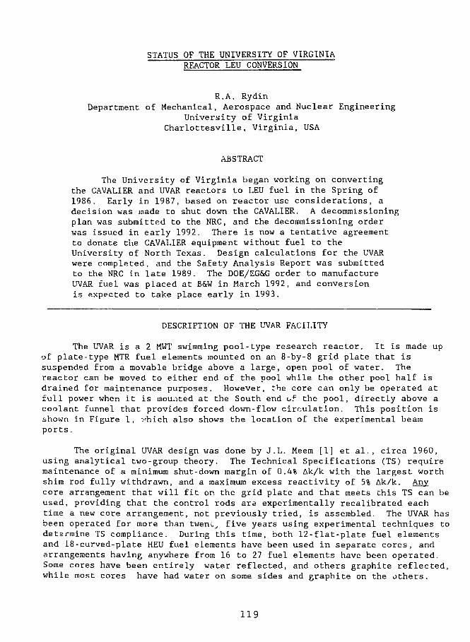
STATUS OF THE UNIVERSITY OF VIRGINIAREACTOR LEU CONVERSION
R.A. RydinDepartment of Mechanical, Aerospace and Nuclear Engineering
University of VirginiaCharlottesville, Virginia, USA
ABSTRACT
The University of Virginia began working on convertingthe CAVALIER and UVAR reactors to LEU fuel in the Spring of1986. Early in 1987, based on reactor use considerations, adecision was made to shut down the CAVALIER. A decommissioningplan was submitted to the NRC, and the decommissioning orderwas issued in early 1992. There is now a tentative agreementto donate the CAVALIER equipment without fuel to theUniversity of North Texas. Design calculations for the UVARwere completed, and the Safety Analysis Report was submittedto the NRC in late 1989. The DOE/EG&G order to manufactureUVAR fuel was placed at B&W in March 1992, and conversionis expected to take place early in 1993.
DESCRIPTION OF THE UVAR FACILITY
The UVAR is a 2 MWT swimming pool-type research reactor. It is made upof plate-type MTR fuel elements mounted on an 8-by-8 grid plate that issuspended from a movable bridge above a large, open pool of water. Thereactor can be moved to either end of the pool while the other pool half isdrained for maintenance purposes. However, the core can only be operated atfull power when it is mouated at the South end of the pool, directly above acoolant funnel that provides forced down-flow circulation. This position isshown in Figure 1, vhich also shows the location of the experimental beamports.
The original UVAR design was done by J.L. Meem [1] et al., circa 1960,using analytical two-group theory. The Technical Specifications (TS) requiremaintenance of a minimum shut-down margin of 0.4% Ak/k with the largest worthshim rod fully withdrawn, and a maximum excess reactivity of 5% Ak/k. Anycore arrangement that will fit or. the grid plate and that meets this TS can beused, providing that the control rods are experimentally recalibrated eachtime a new core arrangement, not previously tried, is assembled. The UVAR hasbeen operated for more than tweni.̂ five years using experimental techniques todetermine TS compliance. During this time, both 12-flat-plate fuel elementsand 18-curved-plate HEU fuel elements have been used in separate cores, andarrangements having anywhere from 16 to 27 fuel elements have been operated.Some cores have been entirely water reflected, and others graphite reflected,while most cores have had water on some sides and graphite on the others.
119
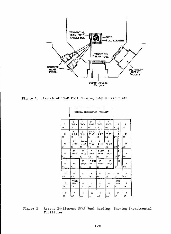
NEUTRONBEAMPORTS
SOUTHEASTACCESS
FACILITY
SOUTH ACCESSFACILITY
Figure 1. Sketch of UVAR Pool Showing 8-by-8 Grid Plate
MINERAL IRRADIATION FACEUTV
G11
G21
G31
G41
G
51
G61
G71
G
81
FV-0512
FV-0622
FV-Q832
FV-0942
G
52
G62
THERRAH
72
G
82
FV-04
13
FV-14
23
f-CR2V-19
33
FV-11
43
FT-13
53
G63
G
73
G83
FV-03
14
F-OUV-18
24
FT-09
34
FV-10
44
F-REGT-32
54
P
64
G
74
G
H4
FV-02
15
FV-27
25
FT-10
35
r-cwT-31
45
FT-14
55
G65
G
75
G
85
FV-0116
FT-0726
FT-1836
FT-3046
FV-12
56
S66
G
76
G
B6
17
27
37
47
R0
AT
I
1
R.
F
C.
57' '
P67
HYDRAH
77
P87
P18
P28
P
38
P48
P58
P68
P78
G
86
Figure 2. Recent 24-Element UVAR Fuel Loading, Showing ExperimentalFacilities
120
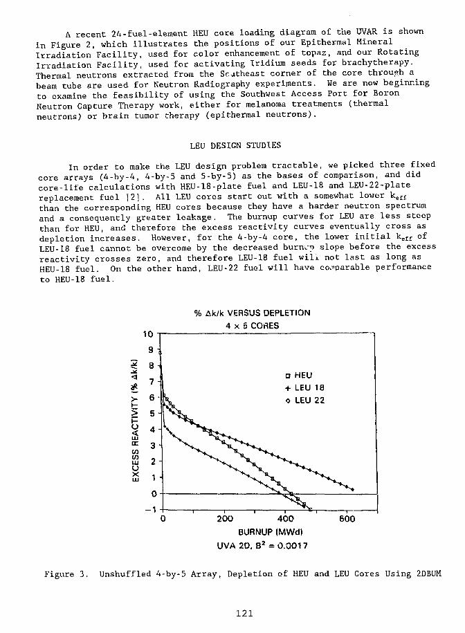
A recent 24-fuel-element HEU core loading diagram of the UVAR is shownin Figure 2, which illustrates the positions of our Epithermal MineralIrradiation Facility, used for color enhancement of topaz, and our RotatingIrradiation Facility, used for activating Iridium seeds for brachytherapy.Thermal neutrons extracted from the Southeast corner of the core throuch a^beam tube are used for Neutron Radiography experiments. We are now beginningto examine the feasibility of using the Southwest Access Port for BoronNeutron Capture Therapy work, either for melanoma treatments (thermalneutrons) or brain tumor therapy (epithermal neutrons).
LEU DESIGN STUDIES
In order to make the LEU design problem tractable, we picked three fixedcore arrays (4-by-4, 4-by-5 and 5-by-5) as the bases of comparison, and didcore-life calculations with HEU-18-plate fuel and LEU-18 and LEU-22-platereplacement fuel [2]. All LEU cores start out with a somewhat lower keffthan the corresponding HEU cores because they have a harder neutron spectrumand a consequently greater leakage. The burnup curves for LEU are less steepthan for HEU, and therefore the excess reactivity curves eventually cross asdepletion increases. However, for the 4-by-4 core, the lower initial keff ofLEU-18 fuel cannot be overcome by the decreased burn..-? slope before the excessreactivity crosses zero, and therefore LEU-18 fuel will not last as long asHEU-18 fuel. On the other hand, LEU-22 fuel will have comparable performanceto HEU-18 fuel.
10
Ak/k VERSUS DEPLETION4 x 5 CORES
D HEU+ LEU 18O LEU 22
200 400
BURNUP (MWd)
UVA2D. B2 = 0.0017
600
Figure 3. Unshuffled 4-by-5 Array, Depletion of HEU and LEU Cores Using 2DBUM
121
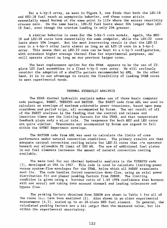
For a 4-by-5 array, as seen in Figure 3, one finds that both the LEU-18and HEU-18 fuel reach an asymptotic behavior, and these cores attainessentially equal burnup at the same point in life where the excess reactivitycrosses zero. On the same basis, LEU-22 fuel lasts about 50% longer than LEU-18 fuel, even though the uranium loading is only 20% greater.
A similar behavior is seen for the 5-by-5 core models. Again, the HEU-18 and LEU-18 cores have essentially the same endpoint, while the LEU-22 corelasts about 50% longer. But the most interesting result is that the LEU-22core in a 4-by-5 array lasts almost as long as an LEU-18 core in a 5-by-5array. This means that an LEU-22 core can be kept in a 4-by-5 configuration,with attendant higher average thermal flux for experimental purposes, anJstill operate almost as long as our previous larger cores,
The best replacement option for the UVAR appears to be the use of 22-plate LEU fuel assemblies in a fixed 4-by-5 core array. We will seriouslyconsider the adoption of a shuffle pattern recommended by ANL. On the otherhand, it is to our advantage to retain the flexibility of loading UVAR coresto meet experimental needs.
THERMAL HYDRAULIC ANALYSIS
The UVAR thermal hydraulic analysis makes use of three basic computercode packages, PARET, THERHYD and NATCON. The PARET code from ANL was used tocalculate an envelope of maximum achievable power transients, based upon pumpcoastdown and period trips, all accompanied by Scram. The net result of allof the PARET analyses is the finding that the control rod release andinsertion times are the limiting factors for the UVAR, and that temperaturefeedback plays only a miuor role. The responses for both HEU and LEU coresare quite similar. Transients not accompanied by Scram are argued to fallwithin the SPERT Experiment envelope.
The NATCON code from ANL was used to calculate the limits of coreperformance under natural convection conditions. The primary results are thatadequate natural convection cooling exists for LEU-22 cores that n*-e operatedbeneath our allowable TS limit of 200 kW. The use of additional fuel platesin our fuel elements increases the amount of natural convection coolingavailable.
The main tool for our thermal hydraulic analysis is the THERHYD code[3], developed at UVA in 1967. This code is used to calculate limiting-powerversus system-flow envelopes for the UVAR, below which all PARET transientsmust lie. The code handles forced convection down-flow, using an axial powerdistribution fit and planar peaking factors from 2DBUM. The limitingcondition is given using a burnout ratio of 1.49 (99% confidence that burnoutwill not occur) and taking into account channel and loading tolerances andbypass flow.
The peaking factors obtained from 2DBUM are shown in Table 1 for all ofthe cores th.jc have been analyzed [2]. Also shown is an older experimentalmeasurement [4,5], scaled up to an 18-plate HEU fuel element. In general, thecalculated peaking factors are a bit larger than the measured value, but liewithin the experimental uncertainty.
122
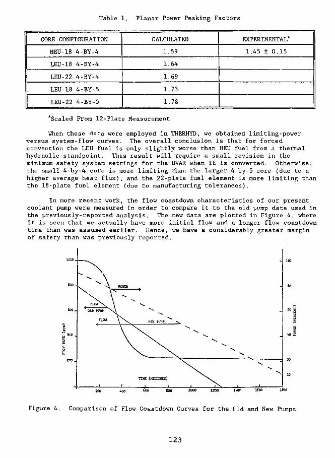
Table 1. Planar Power Peaking Factors
CORE CONFIGURATION
HEU-18 4-BY-4
LEU-18 4-BY-4
LEU-22 4-BY-4
LEU-18 4-BY-5
LEU-22 4-BY-5
CALCULATED
1.59
1.64
1.69
1.73
1.78
EXPERIMENTAL*
1.45 ± 0.15
*Scaled From 12-Plate Measurement
When these Hat-.a were employed in THERHYD, we obtained limiting-powerversus system-flow curves. The overall conclusion is that for forcedconvection the LEU fuel is only slightly worse than HEU fuel from a thermalhydraulic standpoint. This result will require a small revision in theminimum safety system settings for the UVAR when it is converted. Otherwise,the small 4-by-4 core is more limiting than the larger 4-by-5 core (due to ahigher average heat flux), and the 22-plate fuel element is more limiting thanthe 18-plate fuel element (due to manufacturing tolerances).
In more recent work, the flow coastdown characteristics of our presentcoolant pump were measured in order to compare it to the old pump data used inthe previously-reported analysis. The new data are plotted in Figure 4, whereit is seen that we actually have more initial flow and a longer flow coastdowntime than was assumed earlier. Hence, we have a considerably greater marginof safety than was previously reported.
llor lioo lEoo
Figure 4. Comparison of Flow Coastdown Curves for the Cld and New Pumps.
123
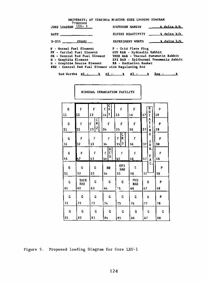
UNIVERSITY OF VIRGINIA Rf ACTOR CORE LOADING DIAGRAM
ProposedOORE LOADING LEU- 1 SHUTDOWN MARGIN t delta k/k
DATE
U-235 GRAMS
EXCESS REACTIVITY
EXPERIMENT WORTH
% delta k/k
* delta k/k
F - Normal Fuel Element P - Grid Plate PlugPF - Partial Fuel Element HYD RAB • Hydraulic RabbitCR - Control Rod Fuel Element THER RAb - Thermal Pneumatic RabbitC - Graphics Element EPI RAB - Epltherraal Pneumatic RabbitS - Graphite Source Element RB - Radiation BasketREG - Control Rod Fuel Element with Regulating Rod
Rod Worths #1 - % 02 - % #3 - t Ree -
MINERAL IRRADIATION FACILITY
G
11
G
21
G
31
G
41
G
51
G
61
G
71
G
81
F
12
F22
F
32
F
4.7
G
52
THERRAB
62
G
72
G
82
F13
23
CR
2
F
33
F
43
G
53
G
63
G
73
G
83
F
14
CR
1
F24
F
34
F44
REG
RB
54
G
64
G
74
G
84
F
15
F
25
F35
CR
3
F
45
EPIRAB
55
G
G
75
G
85
F
16
F26
F36
F
S
56
HYDRAB
66
G
76
G
86
17
27
37
47
5V
0TATIN6
IRR.
FAC.
G
67
G
77
G
87
P
18
P
28
P
38
P
48
P
58
P
68
P
78
G
88
Figure 5. Proposed loading Diagram for Core LEU-1
124
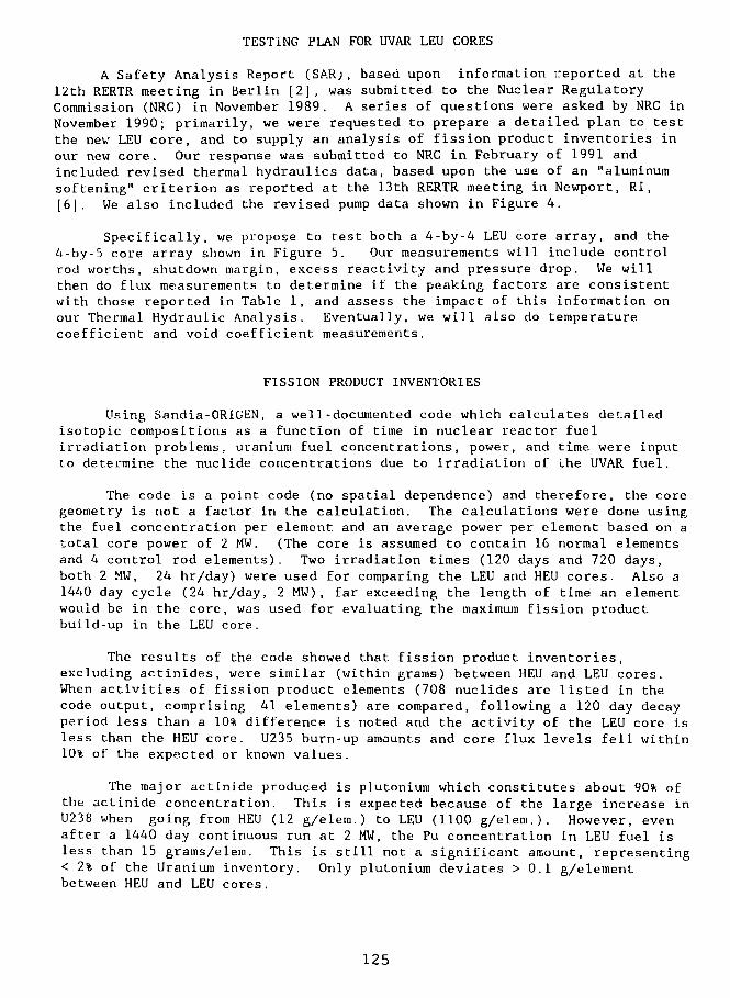
TESTING PLAN FOR UVAR LEU CORES
A Safety Analysis Report (SAR), based upon information reported at the12th RERTR meeting in Berlin [2], was submitted to the Nuclear RegulatoryCommission (NRC) in November 1989. A series of questions were asked by NRC inNovember 1990; primarily, we were requested to prepare a detailed plan to testthe new LEU core, and to supply an analysis of fission product inventories inour new core. Our response was submitted to NRC in February of 1991 andincluded revised thermal hydraulics data, based upon the use of an "aluminumsoftening" criterion as reported at the 13th RERTR meeting in Newport, RI,[6]. We also included the revised pump data shown in Figure 4.
Specifically, we propose to test both a 4-by-4 LEU core array, and the4-by-5 core array shown in Figure 5. Our measurements will include controlrod worths, shutdown margin, excess reactivity and pressure drop. We willthen do flux measurements to determine if the peaking factors are consistentwith those reported in Table 1, and assess the impact of this information onour Thermal Hydraulic Analysis. Eventually, we will also do temperaturecoefficient and void coefficient measurements.
FISSION PRODUCT INVENTORIES
Using Sandia-ORIGEN, a well-documented code which calculates detailedisotopic compositions as a function of time in nuclear reactor fuelirradiation problems, uranium fuel concentrations, power, and time were inputto determine the nuclide concentrations due to irradiation of the UVAR fuel.
The code is a point code (no spatial dependence) and therefore, the coregeometry is not a factor in the calculation. The calculations were done usingthe fuel concentration per element and an average power per element based on atotal core power of 2 MW. (The core is assumed to contain 16 normal elementsand 4 control rod elements). Two irradiation times (120 days and 720 days,both 2 MW, 24 hr/day) were used for comparing the LEU and HEU cores. Also a1440 day cycle (24 hr/day, 2 MW), far exceeding the length of time an elementwould be in the core, was used for evaluating the maximum fission productbuild-up in the LEU core.
The results of the code showed that fission product inventories,excluding actinides, were similar (within grams) between HEU and LEU cores.When activities of fission product elements (708 nuclides are listed in thecode output, comprising 41 elements) are compared, following a 120 day decayperiod less than a 10% difference is noted and the activity of the LEU core isless than the HEU core. U235 burn-up amounts and core flux levels fell within10% of the expected or known values.
The major actinide produced is plutonium which constitutes about 90% ofthe actinide concentration. This is expected because of the large increase inU238 when going from HEU (12 g/elem.) to LEU (1100 g/elem.). However, evenafter a 1440 day continuous run at 2 MW, the Pu concentration in LEU fuel isless than 15 grams/elem. This is still not a significant amount, representing< 2% of the Uranium inventory. Only plutonium deviates > 0.1 g/elementbetween HEU and LEU cores.
125
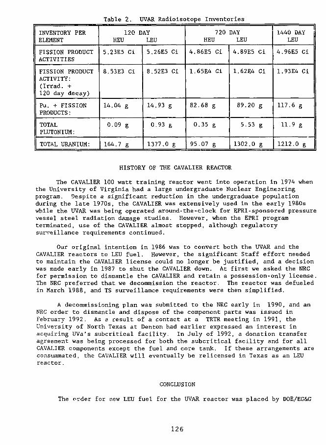
Table 2. UVAR Radioisotope Inventories
INVENTORY PERELEMENT
FISSION PRODUCTACTIVITIES
FISSION PRODUCTACTIVITY:(Irrad. +120 day decay)
Pu. + FISSIONPRODUCTS:
TOTALPLUTONIUM:
TOTAL URANIUM:
120HEU
5.23E5 Ci
8.53E3 Ci
14.04 g
0.09 g
164.7 g
DAYLEU
5.26E5 Ci
8.52E3 Ci
14.93 g
0.93 g
1377.0 g
720HEU
4.86E5 Ci
1.65E4 Ci
82
0
95
68 g
35 g
.07 g
DAYLEU
4.89E5
1.62E4
89.20
5.53
1302.0
Ci
Ci
g
g
g
1440 DAYLEU
4.96E5 Ci
1.93E4 Ci
117.6 g
11.9 g
1212.0 g
HISTORY OF THE CAVALIER REACTOR
The CAVALIER 100 watt training reactor went into operation in 1974 whenthe University of Virginia had a large undergraduate Nuclear Enginesringprogram. Despite a significant reduction in the undergraduate populationduring the late 1970s, the CAVALIER was extensively used in the early 1980swhile the UVAR was being operated around-the-clock for EPRI-sponsored pressurevessel steel radiation damage studies. However, when the EPRI programterminated, use of the CAVALIER almost stopped, although regulatorysurveillance requirements continued.
Our original intention in 1986 was to convert both the UVAR and theCAVALIER reactors to LEU fuel. However, the significant Staff effort neededto maintain the CAVALIER license could no longer be justified, and a decisionwas made early in 1987 to shut the CAVALIER down. At first we asked the NRCfor permission to dismantle the CAVALIER and retain a possession-only license.The NRC preferred that we decommission the reactor. The reactor was defueledin March 1988, and TS surveillance requirements were then simplified.
A decommissioning plan was submitted to the NRC early in 1990, and anNRC order to dismantle and dispose of the component parts was issued inFebruary 1992. As a result of a contact at a TRTR meeting in 1991, theUniversity of North Texas at Denton had earlier expressed an interest inacquiring UVa's subcritical facility. In July of 1992, a donation transferagreement was being processed for both the subcritical facility and for allCAVALIER components except the fuel and core tank. If these arrangements areconsummated, the CAVALIER will eventually be relicensed in Texas as an LEUreactor.
CONCLUSION
The order for new LEU fuel for the UVAR reactor was placed by DOE/EG&G
126
at Babcock and Wilcox in March 1992. We will receive a minimum core load plusenough extra fuel for around-the-clock operation for a year. This constitutes2b full fuel elements, 5 control elements, 2 partial elements and 2 dummyelements. The estimated replacement cost per element is approximately$20,000, making the total order worth approximately $600,000. The dummyelements are expected to be available for trial fitting in the core grid piatein late September, and the first LEU core is expected in December 1992.Conversion will tentatively take place early in 1993, subject to availabilityof a spent-fuel shipping cask and acceptance of spent HEU fuel at a governmentfacility.
The total amount of monty supplied to UVa by DOE for design studiesamounted to $120,000. This financed 3 Master of Science theses [7,8,9], pluspartial support of several other students. Unreimbursed costs to theUniversity amount to about $40,000, with further Faculty and Staff costsexpected during the LEU first-core testing phase. Over the long term, the useof the longer-life 22-plate fuel elements will produce savings in staff timefor refuelling activities, require fewer spent fuel shipments, and reduce thecost to DOE of resupplying fuel for the UVAR.
REFERENCES
1. J.L. Meem, Two Group Reactor Theory. Appendix A, Gordon and BreachScience Publishers, New York, N.Y., 1964.
2. R.A. Rydin, D.W. Freeman, B. Hosticka and R.U. Mulder, "Safety Analysisfor the University of Virginia Reactor LEU Conversion", Proceedings ofthe Xllth International Meeting, Reduced Enrichment for Research andTest Reactors, Berlin, FRG, 10-14 September 1989, pp 211-226.
3. J.A. Dahlheimer, "Thermal-Hydraulic Safety Analysis of a Pool Reactor",M.S. Thesis, University of Virginia, 1967.
4. W.K. Brunot, "An Analysis of Fuel Element Surface Temperature andCoolant Flow Rate in the University of Virginia Reactor," M.S. Thesis,University of Virginia, 1961.
5. R.L.J. McGuiness, "Thermal-Hydraulic Safety Analysis of 18-Plate ReactorFuel Elements", B.S. Thesis, University of Virginia, 1973.
6. B. Hosticka, C. Mora and R.A. Rydin, "State of the LEU Conversion Effortat the University of Virginia Reactor, Proceedings of the XIIIthInternational meeting, Reduced Enrichment for Research and TestReactors, Newport, RI, 23-27 September 1990.
7. M.K. Fehr, "Design Optimization of a Low Enrichment University ofVirginia Nuclear Reactor," M.S. Thesis, University of Virginia, January1989.
8. S. Wasserman, "Effective Diffusion Theory Cross Sections for UVARControl Rods," M.S. Thesis, University of Virginia, January 1990.
9. D.W. Freeman, "Neutronic Analysis for the UVAR Reactor HEU to LEUConversion Project," M.S. Thesis, University of Virginia, January 1990.
127
COMPLETION OF THE OSURR FUEL CONVERSION AND POWER UPGRADE
J. W. Talnagi* and T. Aldemir"
"The Ohio State University Nuclear Reactor Laboratory12*5 Kinnear Road, Columbus, Ohio 43212 U.S.A.
"The Ohio State University, Nuclear Engineering Program206 West 18th Avenue, Columbus, Ohio 43210 U.S.A.
ABSTRACT
The 10 kW Ohio State University Research Reactor (OSURR) went critical with the standardized20% enrichment U3Si2 - Al fuei elements on IS December 1983 and has been operating at powerlevels up to 500 kW since 19 December 1991 with natural convection core cooling. The computa-tional and engineering work related to the conversion/upgrade process is described.
INTRODUCTION
Conversion of The Ohio State University Research Reactor (OSURR) began in August, 1985, with theaward of a DOE grant, matched in part with University funds, for a program to convert the OSURR fuel from93% enrichment UA1 fuel to a nominal 20% enrichment U3Si2 - Al fuel, and in the process increase the operat-ing power from !0 to 500 kW steady-state thermal output. The program consisted of three phases: analyses: ofthe low- enrichment uranium (LEU) fueled OSURR core under various operating conditions, licensing activitiesincluding the submission of a Safety Analysis Report (SAR) for the upgraded, LEU fueled OSURR, and Facilityengineering related to both LEU conversion and power upgrade.
This paper will provide a summary of the overall program, including discussion of the conversion/upgradeprogram history, results obtained and experience gained and an evaluation of the program benefits to theOSURR.
BACKGROUND
OSURR Operational HistoryIn many ways, the history of the OSURR facility is typical of university- based research reactors in the
United States. Initial construction funds were provided in part by the Atomic Energy Commission, the predeces-sor agency of the U.S. Department of Energy (DOE), with the intent of providing a research and educationalfacility for The Ohio State University and other educational institutions. Construction began in 1960, with com-pletion and initial operation of the reactor in 1961. The design chosen was based on the original MTR design,and construction patterned after the Bulk Shielding Reactor (BSR) at Oak Ridge National Laboratory. TheNuclear Products Division of the Lockheed Georgia Company was the reactor system supplier.
Operating power was deliberately restricted to 10 kW steady-state thermal output for several reasons.First, it was thought that for a facility whose primary mission was to be instruction and education, the ability toperform precise, repeatable core physics experiments would be of primary importance. Second, because of thegeographical proximity of the Battelle Memorial Institute's research reactor (a 2 MW facility), a high-flux reac-tor would be available and relatively affordable for researchers desiring higher flux levels. Also, the Universitydid not wish to engage in the relatively complex operations of fuel management and offsite shipment of irradi-ated fuel, as is required for higher power reactors. Finally, it was thought that adequate University fundingwould be made available to the OSURR to continue its operation as a primarily instructional facility for the life-time of the reactor.
128
System DescriptionAs noted above, the OSURR is patterned after the MTR/BSR designs, featuring an open reactor pool con-
taining a light-water moderated reactor core, with a total of four control rods. Initial core loading was withhigh-enrichment uranium (HEU) fuel elements of the flat-plate, picture frame type, with a nominal 3-inch by 3-inch cross-section. The HEU fuel elements also had a cylindrical lower end box which allowed insertion into agrid plate having a 5 x 6 array of possible fuel positions, thus allowing up to 30 elements to be placed on thegrid plate. Experimental facilities included an air-filled central irradiation tube (denoted the CIF, for CentralIrradiation Facility), a set of graphite-bearing isotope irradiation elements (GIlEs), a pneumatic transfer system(Rabbit), and two 6-inch inner-diameicr beam ports located along one edge of the core. The OSURR core isreflected on two sides by giaphite slabs forming the end extensions of graphite-loaded thermal columns.
OSURR control rods consist of three shim safety rods and a single regulating rod. The shim safety rodsarc grooved stainless steel, oval-shaped solid rods having a nominal 1.5%-wcighi natural boron concentration,while the regulating rod is solid, ungrooved stainless steel. The poison section length of ihc shim safely rods isa nominal 61 centimeters.
The OSURR reactor pool is 20 feel deep, with a minimum depth of 15 feet above the core, and contains5800 gallons of demincralized, filtered light water. The core is cooled by natural convection, with the bulk pooltemperature at near room temperature and the pool surface at atmospheric pressure.
Operation of the HEU-fueted OSURR at 10 kW required loading of a core with a 5 x 5 fuel clementarray, with the CIF occupying the central grid position, and the control rods positioned symmetrically within thisarray. A row of graphite- bearing elements was loaded in the remaining 5 x 1 row of grid plate positions. Thisarrangement, denoted as Standard Core I. was the nominal OSURR core configuration, utilizing ihe originalHEU fuel elements, for over 25 years. During this time, which included regular fuel element inspections andpool water radionuclide assays, no abnormal fuel element behavior was noted.
Facility UtilizationOSURR utilization is typical of that for low and intermediate power research reactors in university set-
tings. Instructional utilization accounts for about one-half of all operational hours, with various experiments andresearch use accounting for the remainder of operating hours, instructional utilization includes various studentlaboratory exercises such as subcritical multiplication and approach to critical experiments, flux mapping, controlrod worth measurements, reactor transfer function determination, void coefficient measurement, and analysis ofdelayed neutron parameters. Research use includes material irradiation, neutron activation analysis, neutronradiography, neutron spectral measurement, and boron neutron capture therapy. Typical OSURR energy outputwhen licensed for 10 kW maximum power was about 2000 kW-hours per year.
Conversion/Upgrade Program
Initial consideration of convening the OSURR to LEU fuc! began in 1984, when it became clear that theU.S Nuclear Regulatory Commission (NRC) would likely pass a rule requiring the use of LEU, where feasible,in domestic, non- power research reactors falling under the NRC's jurisdiction. In March, 1985. a proposal wassubmitted to DOE to provide funds, to be matched in part by the University, for LEU conversion and poweruprating of the OSURR. Ideally, DOE funds would be directed towards fuel conversion activities, while Univer-sity funds would support the power upgrade effort. The DOE award was made in July, 1985, with work begin-ning in August, 1985.
The overall purpose of the program was to accomplish fuel conversion to DOE- standard U3Si2 - Al LEUfuel while concurrently increasing the OSURR operating power from 10 to 500 kW steady-state thermal power.Towards these ends, the following goals were established:
1. Complete removal of the original HEU fuel, with eventual shipment to DOE's Savannah River Plant forreprocessing, and replacement with DOE-standard U3Si2 - Al LEU fuel.
2 Restoration of OSURR operations at power levels up to 10 kW using an LEU core, measurement ofsafety-related core parameters.
3. Concurrent facility engineering activities directed towards installation of a heat removal system to allowpower operations above 10 kW.
4. A stepwise increase in OSURR operating power, ultimately reaching 500 KW, with various engineeringmeasurements performed at each chosen operating power level step.
The overall motivation for undertaking this program was twofold. First, fuc! conversion would meet theimpending NRC requirement and provide a "test case" for the planned licensing process. Second, the opera-tional situation had changed from that which was present when the OSURR was initially planned as a low-
129
power instructional facility. The Baltelle Research Reactor was decommissioned in mid-1970's. This made ahigh flux facility relatively diffucult to access conveniently. Also, university support for the OSURR operationswas substantially reduced in the early 1980's and it became necessary to generate a substantial part of the facil-ity budget from outside funding. To do this, it was necessary to broaden the potential user base which would befacilitated by having higher fluxes available to the users. A 500 kW power level was chosen since it would pro-vide a central core fiux at about 1013 neutrons/cm2.s and allow various material irradiation experiments whilemaintaining natural convection as the primary heat removal mechanism.
The. program was organized into two working groups: the analytical and computational personnel, and thelicensing and engineering group. Naturally, close communication between the two groups was established sincethe work of one would necessarily affect that of the other. It turned out that the majority of personnel assignedto the analytical group consisted of Nuclear Engineering Program graduate students and faculty, while theengineering group was composed largely of OSURR operating staff, supplemented by private consultants andengineering firms, 'vhen necessary.
Program progress and results to date have been largely reported in previous publications and presenta-tions.wo Briefly, the overall program started in August, 1985, with the computational and analytical studies tak-ing approximately two years to complete. These studies are summarized in the following section. Results ofthe analytical and computational work were used to write a Safety Analysis Report (SAR) for the OSURRfueled with LEU, and operating at power levels up to 500 kW. The SAR was submitted to the NRC in October,1987. After resolution of NRC's questions and points of contention, an Order from the NRC requiring LEUconversion of the OSURR was issued on 27 September 1988. This Order appeared in the Federal Register (FR)on 4 October 1988, and, allowing that there were no petitions for leave to intervene filed within the required30-day period from the appearance of the Order in the FR, the Order became effective on 3 November 1988.Since the LEU fuel had arrived at the OSURR facility on 8 November 1988, HEU core unloading began essen-tially immediately, with the complete unloading being completed by late November 1988. LEU fuel elementswere loaded starting on 7 December 1988, with attainment of a critical geometry on 15 December 1988. Rou-tine OSURR operations at power levels up to 10 kW were resumed in January, 1989. Concurrent licensingactivities and facility engineering work continued during the following months directed towards increasedoperating power.
Licensing issues related to increased operating power were resolved between the NRC and OSURR by 30April 1990. The NRC issued revised OSURR Technical Specifications for operating power levels up to 500 kWon 14 November, 1990. Facility engineering work allowing operating power up tc 100 kW were completed by11 September, 1991. Testing at 50 kW ami 100 kW was completed on 18 September, 1991 and 17 October,1991, respectively. Further engineering work necessary for operation up to 500 kW was completed by 30November, 1992, with testing at 250 kW and 500 kW completed on 18 December, 1992 and 19 December,1992, respectively. Routine operations of the OSURR at power levels up to 500 kW have been conducted since.
ANALYTICAL PROGRAM
The main objective of the analytical program were to identify core and pool configurations which wouldsatisfy the following criteria:1. The cold, clean core must have sufficient excess reactivity to compensate for experiment worth (0.7%
Ak/k), temperature and xenon feedback at full power (500 kW) and other bumup effects (>0.5% Ak/k)while maintaining a minimum of 1.5% Ak/k shutdown margin with the highest worth rod stuck out.
2. The margin to onset of nucleate boiling (ONB) in the hot channel should be a minimum of 20% at fullpower.
3. The thermal neutron flux levels at the CIF and the beam tube positions should not be less than 1 x 10¹³
and 7 x 10¹²n/cm2s, respectively.
4. The pool configuration should lead to as low as reasonable achievable pool top 16N activity and also max-imize the inlet water temperature to the primary side of the pool heat removal system (PHRS) to improveheat exchanger efficiency.
The related neutronic and thermal-hydraulic work has been described in detail in previous presentationsand publications.4'5"7-10 The LEU fuel elements were chosen to have the same outer dimensions the as the HEUelements (i.e. 7.62 x 7.62 cm in cross-section), with the standard elements (SEs) consisting of 18 1.27 mm thickplates 16 of which had U3Si2 - Al meat containing 12.5 g of 235U per plate. The remaining two plates are pureAI and placed on the outside for mechanical protection. The control elements has 10 fueled and 2 pure Alplates with the same dimensions as the standard fuel element plates. The non-fueled plates serve as guide platesfor the control rods.
130
The analytical program was able to identify two 18 SE and one 17 SE core configurations that satisfy theabove criteria. In addition, another 16 SE core configuration was identified with 1.5% Ak/k excess reactivity forthe initial conversion and testing phase at 10 kW. The computational work indicated that Criterion #4 abovewould be achieved if ihe core were contained in a shroud with a 75 cm chimney, with the water to the primaryside of the PHRS drawn from the chimney and passed through an insulated decay tank placed in the reactor poolbefore entering PHRS main heat exchanger.2-6'9
FUEL CONVERSION ACTIVITIES
HEU RemovalRemoval of the HEU fuel from the OSURR core, which had hitherto composed the only operational core
ever used in the history of the OSURR, was a key milestone nf the overall program. Prior to the actual HEUremoval, a series of preliminary activities were planned and completed. Lacking immediate access to anapproved fuel transport cask, plans were made for temporary onsite storage of the HEU fuel, pending ultimateshipment to Savannah River. The logical storage location was the Bulk Shielding Facility (BSF) pool, locatedimmediately adjacent to the OSURR pool, but having a separate water cleanup system, and having sufficientvolume and depth for storage of irradiated but unusable HEU fuel elements.
The NRC approval for this storage plan was sought and ultimately obtained. Facility modifications to storethe HEU fuel included installation of security systems in and around the BSF pool, design, analysis, and fabrica-tion of criticaluy-safe storage racks for the fuel elements, and design and construction of a transfer cask to movethe irradiated fuel elements from the reactor pool to the BSF pool.
The transfer cask was necessitated by the lack of a direct portal (canal) between the two pools, and theneed to keep doses to personnel as low as reasonably achievable. Design constraints on the cask included reduc-ing near- surface doses rates to as low a value as possible for the most highly-inadiated fuel element, whileallowing the cask to be lifted using the 3-ton bridge crane available in the OSURR facility. These constraintsresulted in the design and construction of a cask having an 3-inch thick wall, shaped into a cylinder with anouter jacket of mild steel, a removal lid, and a cavity volume sufficient to accommodate a single HEU fuel ele-ment.
Two storage racks were fabricated, each capable of holding 16 fuel elements in a 2 x 8 array. Theseracks, fabricated from sheet and angle aluminum components, were analyzed for crilicality safety assuming thetwo fully-loaded racks were placed adjacent to each other and submersed in purified, demineralized light water.Criticality safety was assured by specifying the pitch of the fuel elements sufficient to produce a multiplicationfactor of an infinite array of the OSURR HEU fuel elements of less than one. Other features included a widebase to prevent lipping, and spacers to prevent adjacent placement of the racks.
Administrative activities necessary for HEU removal included development and approval of rack place-ment and transfer cask handling procedures, post-removal fuel inspection and monitoring activities, and ongoingsurveillance of BSF pool water purity and radionuclide content. To the extent possible, all administrative andprocedure development work was completed prior to beginning fuel removal.
A decay period of about 3 days was allowed between the last operation of the OSURR and the beginningof fuel removal. Actual fuel removal took about one week to complete, including various dose rate surveys andinspections of the removed elements that might not have been strictly required. The highest near-contact doserale measured for the removed elements was approximately 120 R/hr in air, detected with a remotely-operatedionization chamber. No measurable personnel doses were recorded for ihe entire HEU removal operation, whichdemonstrated the effectiveness of the handling procedures and techniques.
LEU Core InstallationLEU core loading was accomplished using procedures and tools used for standard HEU fuel handling,
since the design of the LEU fuel elements specified physical compatibility with the existing OSURR grid plateand fuel handling tools. Fuel loading order was dictated by the approved OSURR operating procedure for con-ducting a critical experiment. Actual loading time was aboul one week, allowing time for data collection andanalysis preceding and following each incremental loading.
Results of the initial core loading experiments yielded data on a minimum critical loading, and a subse-quent configuration suitable for operations up to 10 kW power. Comparisons were made with predicted results.
OSURR operations at 10 kW were conducted for the following year, with further LEU core loadingactivity beginning on 7 July, 1991, related to higher-power operations. Core geometry was changed to increaseexcess reactivity to allow for temperature feedback and xenon poisoning, based on predicted core behavior. Afinal core configuration suitable for power operations up to 500 kW was attained on 16 July, 1991.
131
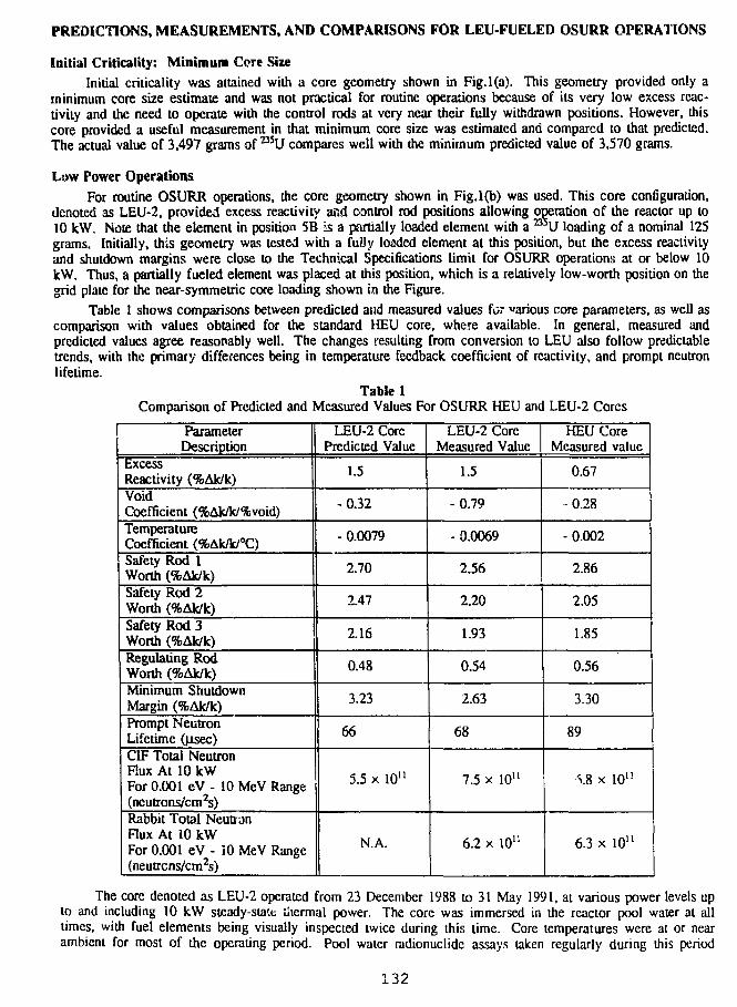
PREDICTIONS, MEASUREMENTS, AND COMPARISONS FOR LEU-FUELED OSURR OPERATIONS
Initial Criticality: Minimum Core SizeInitial criticality was attained with a core geometry shown in Fig.l(a). This geometry provided only a
minimum core size estimate and was not practical for routine operations because of its very low excess reac-tivity and the need to operate with the control rods at very near their fully withdrawn positions. However, thiscore provided a useful measurement in that minimum core size was estimated and compared to that predicted.The actual value of 3,497 grams of BSU compares well with the minimum predicted value of 3,570 grams.
Low Power OperationsFor routine OSURR operations, the core geometry shown in Fig.l(b) was used. This core configuration,
denoted as LEU-2, provided excess reactivity and control rod positions allowing operation of the reactor up to10 kW. Note that the element in position 5B Is a partially loaded element with a B U loading of a nominal 125grams. Initially, this geometry was tested with a fuOy loaded element at this position, but the excess reactivityand shutdown margins were close to the Technical Specifications limit for OSURR operations at or below 10kW. Thus, a partially fueled element was placed at this position, which is a relatively low-worth position on thegrid plate for the near-symmetric core loading shown in the Figure.
Table 1 shows comparisons between predicted and measured values for various core parameters, as well ascomparison with values obtained for the standard HEU core, where available. In general, measured andpredicted values agree reasonably well. The changes resulting from conversion to LEU also follow predictabletrends, with the primary differences being in temperature feedback coefficient of reactivity, and prompt neutronlifetime.
Table 1Comparison of Predicted and Measured Values For OSURR HEU and LEU-2 Cores
ParameterDescription
ExcessReactivity (%Ak/k)VoidCoefficient (%Ak/k/%void)TemperatureCoefficient (%AJc/k/°C)Safety Rod 1Worth (%Ak/k)Safely Rod 2Worth (%Ak/k)Safety Rod 3Worth (%Ak/k)Regulating RodWorth (%Ak/k)Minimum ShutdownMargin (%Ak/k)Prompt NeutronLifetime (jisec)CIF Total NeutronFlux At 10 kWFor 0.001 eV - 10 MeV Range(neutrons/cm2s)Rabbit Total NeutronFlux At 10 kWFor 0.001 eV - 10 MeV Range(neutrcns/cm2s)
LEU-2 CorePredicted Value
1.5
-0.32
- 0.0079
2.70
2.47
2.16
0.48
3.23
66
5.5 x 10"
N.A.
LEU-2 CoreMeasured Value
1.5
-0.79
-0.0069
2.56
2.20
1.93
0.54
2.63
68
7.5 x 10"
6.2 x 10"
HEU CoreMeasured value
0.67
• 0.28
-0.002
2.86
2.05
1.85
0.56
3.30
89
v8 x 10"
6.3 x 10"
The core denoted as LEU-2 operated from 23 December 1988 to 31 May 1991, at various power levels upto and including 10 kW steady-state thermal power. The core was immersed in the reactor pool water at alltimes, with fuel elements being visually inspected twice during this time. Core temperatures were at or nearambient for most of the operating period. Pool water radionuclide assays taken regularly during this period
132
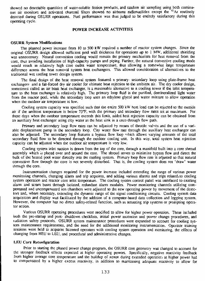
showed no detectable quantities of water-soluble fission products, and random air sampling using both continu-ous air monitors and activated charcoal filters showed no airborne radionuclides except the 41Ar routinelydetected during OSURR operations. Fuel performance was thus judged to be entirely satisfactory during thisoperating cycle.
POWER INCREASE ACTIVITIES
OSURR System ModificationsThe planned power increase from 10 to 500 kW required a number of reactor system changes. Since the
original OSURR design allowed sufficient pool wall thickness for operations up to 1 MW, additional shieldingwas unnecessary. Natural convection cooling would remain the primary mechanism for heat removal from thecore, thus avoiding installation of high-capacity pumps and piping. Further, the natural convective cooling modewould result in relatively high core outlet water temperature, thus allowing a somewhat large temperaturedifference across the heat removal system heat exchangers. This allowed consideration of alternatives to thetraditional wet cooling tower design system.
The final design of the heat removal system featured a primary- secondary loop using plate-frame heatexchangers and a fan-forced dry air cooler for ultimate heat rejection to the ambient air. The dry cooler design,sometimes called an air blast heat exchanger, is a reasonable alternative to a cooling tower if the inlet tempera-ture to the heat exchanger is relatively high. The primary loop fluid is the purified, demineralized light waterfrom the reactor pool, while the secondary loop uses an ethylene glycol and water mixture to allow operationwhen the outdoor air temperature is low.
Cooling system capacity was specified such that the entire 500 kW heat load can be rejected to the outsideair if the ambient temperature is below 73°F, with the primary and secondary flow rates set at maximum. Forthose days when the outdoor temperature exceeds this limit, added heat rejection capacity can be obtained froman auxiliary heat exchanger using city water as the heat sink in a once-through flow path.
Primary and secondary loop flow rates can be adjusted by means of throttle valves and the use of a vari-able displacement pump in the secondary loop. City water flow rate through the auxiliary heat exchanger canalso be adjusted. The secondary loop features a bypass flow loop which allows varying amounts of the totalsecondary fluid flow to be directed through the outdoor cooling unit. In this way, total system heat rejectioncapacity can be adjusted when the outdoor air temperature is very low.
Cooling system inlet suction is drawn from the top of the core, through a manifold built into a core shroudassembly which is placed over and around the core. The shroud serves to minimize bypass flow and direct thebulk of the heated pool water directly into the cooling system. Primary loop flow rate is adjusted so that naturalconvective Sow through the core is not severely disturbed. That is, the cooling system does not "draw" waterthrough the core.
Instrumentation changes required for the power increase included extending the range of various powermonitoring channels, changing alarm and trip setpoints, and adding various alarms and trips related, to coolingsystem operation and reactor core inlet temperature. The cooling system control panel was interfaced to existingalarm and scram buses through isolated, redundant alarm modules. Power monitoring channels utilizing com-pensated and uncompensated ion chambers were adjusted to the new operating power by movement of the detec-tors and, where necessary, extending the dynamic range of the signal conditioning circuits. Cooling system dataacquisition and display was facilitated by the addition of a computer-based data collection and logging system.However, the computer has no direct safety-related function, such as actuating trip systems or prompting opera-tor action.
Various OSURR operating procedures were modified to allow for higher power operation. These includedboth the pre-startup and post- shutdown checklists, initial power ascension and power change procedures, andradiation safety protocols. OSURR system maintenance procedures were expanded to account for cooling sys-tem maintenance requirements, and the need for the additional monitoring instrumentation. Operator trainingsessions were held to acquaint licensed operators with cooling system operation and monitoring, the effects ofchanging from HEU to LEU, and procedural and administrative changes.
LEU Core Reconfiguration
Prior to starting the phased power change program, the OSURR core geometry was changed to account forthe stronger feedback effects expected at higher operating powers. Specifically, negative reactivity feedbackfrom higher average core temperature and the buildup of xenon during extended operation at higher power hadto compensated by a higher excess reactivity, in addition to maintaining adequate reactivity to allow for
1 3 3
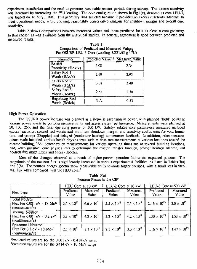
experiment installation and the need to generate reasonable reactor periods during startup. The excess reactivitywas increased by increasing the 235U loading. The coie configuration shown in Fig.l(c), denoted as core LEU-3,was loaded on 16 July, 1991. This geometry was selected because it provided an excess reactivity adequate tomeet operational needs, while allowing reasonably conservative margins for shutdown margin and overall corereactivity.
Table 2 shows comparisons between measured values and those predicted for a as close a core geometryto that chosen as was available from the analytical studies. In general, agreement is good between predicted andmeasured results.
Table 2Comparison of Predicted and Measured Values
For OSURR LEU-3 Core (Loading 3,821.65 g 235U)
ParameterExcessReactivity (%Ak/k)Safety Rod 1Worth (%Ak/k)Safety Rod 2Worth (%Ak/k)Safety Rod 3Worth (%Ak/k)Regulating RodWorth (%Ak/k)
Predicted Value | Measured Value
2.08
2.69
3.01
2.58
N.A.
2.34
2.95
2.49
2.30
0.53
High-Power OperationThe OSURR power increase was planned as a stepwise ascension in power, with planned "hold" points at
various power levels to perform measurements and assess system performance. Measurements were planned at50, 100, 250, and the final operating power of 500 kW. Safety- related core parameters measured includedexcess reactivity, control rod worths and minimum shutdown margin, and reactivity coefficients for void forma-tion, and prompt (Doppler) and delayed (moderator heating) temperature feedback. In addition, other measure-ments made included various health physics tests such as dose rate measurements at various locations around thereactor building, 41Ar concentration measurements for various operating times and at several building locations,and, when possible, core physics tests to determine the reactor transfer function, prompt neutron lifetime, andneutron flux magnitudes and energy spectra.
Most of the changes observed as a result of higher-power operation follow the expected patterns. Themagnitude of the neutron flux is significantly increased in various experimental facilities, as listed in Tables 3(a)and 3(b). The neutron energy spectra show measurable shifts towards higher energies, with a small loss in ther-mal (lux when compared with the HEU core.1
Table 3(a)Neutron Fluxes in the CIF
Flux Type
Total NeutronFlux For 0.001 eV - 18 MeV(neutrons/cm2s)Thermal NeutronFlux For 0.001 eV - 0.2 eV"(neutrons/cm^s)Epithermal NeutronFlux For 0.2 eV - 18 Mevb
(neutrons/cm2s)
HEU Core at 10 kWPredicted
Value
5.4 x 10"
3.3 x 10"
2.1 x 10"
MeasuredValue
6.6 x 10"
4.3 x 10"
2.3 x 10"
LEU-2 Core at 10 kWPredicted
Value
5.5 x 10"
3.2 x 10"
2.3 x 10"
MeasuredValue
7.5 x 10"
4.2 x 10"
3.3 x 10"
LEU-3 Core at 500 kWPredicted
Value
2.46 x 10¹³
1.30 x 10¹³
1.16 x 10¹³
MeasuredValue
3.0 x 10¹³
1.53 x 10¹³
1.47 x 10¹³
'Predicted values are for the 0.001 eV - 0.414 eV rangebPrcdicted values are for the 0.414 eV - 10 MeV range
134
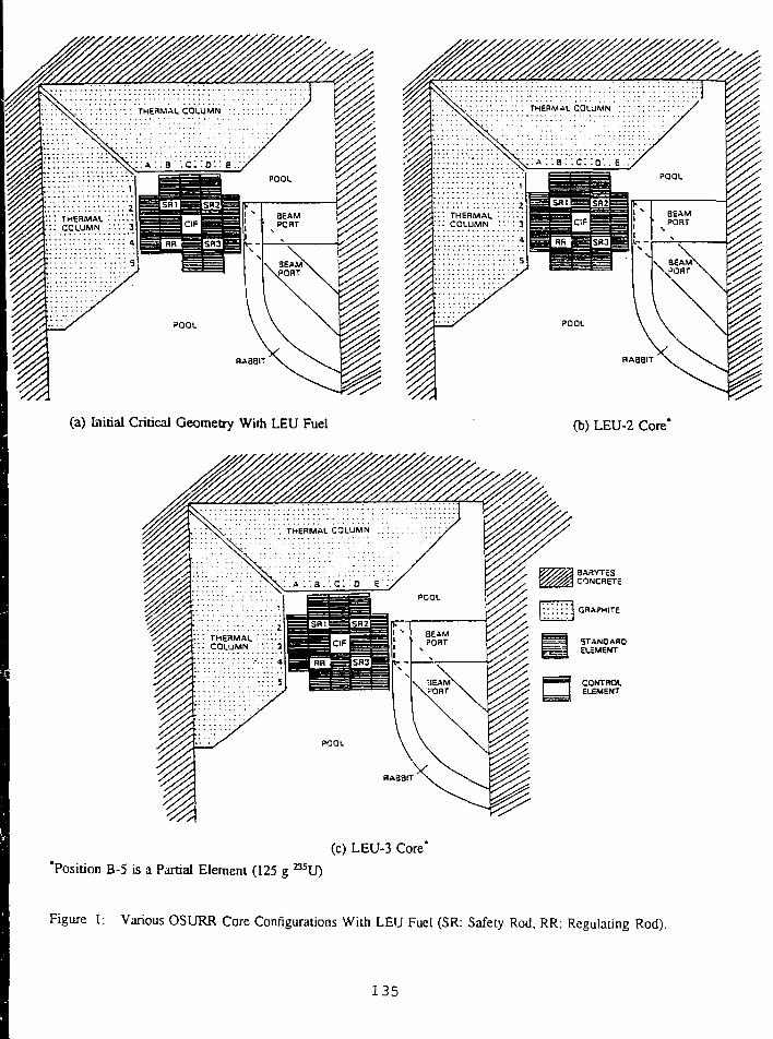
• I(a) Initial Critical Geometry Wiih LEU Fuel (b) LEU-2 Core*
(c) LEU-3 Core"
'Position B-5 is a Partial Element (125 g n 5U)
Figure 1: Various OSURR Core Configurations With LEU Fuel (SR: Safety Rod. RR: Regulating Rod).
135
Table 3(b)Measured Neutron Fluxes in the Rabbit
Total NeutronFlux For 0.001 eV - 18 MeV(neutrons/cm2s)Thermal NeutronFlux For 0.001 eV - 0.2 eV(neutrons/cm2s)Epithermal NeutronFlux For 0.2 eV - 18 MeV(neutrons/cm2s)
HEU Core at 10 kW
6.4 x 10'°
4.5 x 10'°
1.9 x 10'°
LEU-2 Core
6.2 x
4.4 x
1.8 x
at 10 kW
10'°
10'°
10'°
LEU-3 Core
2.7 x
1.8 x
9.0 x
at 500 kW
l.O12
1012
10"
Operations at higher power result in measurable temperature feedback during operation and, for longer runtimes, xe.ion feedback. The additional excess reactivity for core LEU-3 has proven adequate to compensate forthese feedback effects. Previous operations at lower power did not produce measurable effects, thus allowinglower excess reactivity.
As expected, higher dose rates and increased 41Ar concentrations were measured at various locationsaround the reactor building. However, nothing has been detected that would indicate the potential for violationof regulations, or the ALARA guidelines followed at the OSURR. The highest measured dose rates are at thepool surface directly above the reactor core. At full power, the surface dose rate is on the order cf 70 mr/hr.However, this position, located over the surface of the pool, is not considered to be a routinely accessible loca-tion. At the edge of the pool, which is the nearest accessible area to this location, dose rates on the order of 40mr/hr have been measured. During full power operations, access to this area is limited by administrative pro-cedures.
After nearly one year of operation at higher power levels, LEU fuel performance has been entirely satis-factory. Regular radionuclide assay of the pool water has not detected any trace of fission products, and visualinspection of the fuel elements has not revealed any abnormal behavior. Because of the somewhat limited dutycycle to this time, fuel replacement as a result of bumup has not been necessary.
S U M M A R Y AND C O N C L U S I O N S
OSURR fuel conversion and power upgrade has been successfully completed. The analytical program pro-vided accurate predictions of the LEU-fueled OSURR characteristics when operating at various power levels.This allowed preparation of an SAR adequate for relicensing of tho reactor for L E U fuel use at higher operatingpower. Facility engineering to add a heat removal system and upgrade instrumentation was completed, andhigher power operation was attained within a reasonable time. LEU fuel performance has been completely satis-factory. The changes resulting from LEU conversion have not had a severe adverse impact on OSURR opera-tions as a general-purpose research reactor. Indeed, when coupled with a power increase effort, LEU conversioncan provide an opportunity for low and intermediate power research reactors to significantly enhance their poten-tial utilization. In this context, the experience can only be viewed as a positive one for the OSURR.
R E F E R E N C E S
1. J. W. Talnagi, L. A. Heimberger, T. Aldemir, "Prediction and Measurement of the Neutron Environmentin OSURR Experimental Facilities Following Conversion to LEU", to appear in the Proceedings of the1990 International Meeting on Reduced Enrichment for Research and Test Reactors, Newport, RhodeIsland (Sept 24-27, 1990)
2. T. Aldemir, J. W. Talnagi, D. W. Miller, "Analytical, Engineering and Licensing Aspects of the OSURRLEU Conversion/Upgrade", to appear in the Proceedings of the 1988 International RERTR Meeting, SanDiego, California (Sept. 18-22, 1988)
3. J. W. Talnagi, T. Aldemir, "Initial Testing of The Ohio State University Research Reactor LEU Core",Proc. XHth International Meeting on Reduced Enrichment for Research and Test Reactors, G. Thamm, M.Brandt (Eds.), 303-311, Konferenzen des Forschungszentrums Julich, Band 4 , KFA M i c h , Germany(1991)
136
4. T. Aldcmir, J. W. Talnagi, D. W. Miller, "Low Enriched Uranium Conversion/Upgrade of The Ohio ?'ateUniversity Research Reactor", Nurt. TechnoL. 86. 248-263 (September 1989).
5. M. Belhadj, T. Aldemir, R. N. Christensen, "Onset of Nucleate Boiling in Thin Rectangular ChannelsUnder Low-Velocity, Upward-Flow Conditions", Nucl. TechnoL, 82, 330-340 (September 19^8)
6. T. Aldemir, J. W. Talnagi, D. W. Milier, "System Design For the Low Enriched UraniumConversion/Power Upgrade of a Natural Convection Cooled Research Reactor", 50 Years With NuclearFission, 767-774, American Nuclear Society, LaGrange Park, IL (1989)
7. H. S. Aybar, T. Aldemir, "An Investigation of the Effect of Partially Inserted Rods on Power Peaking andRod Worth for the LEU Conversion Upgrade of OSURR", Proc. 1988 Int. Reactor Physics Conf., II, 453-462, American Nuclear Society, LaGrange Park, IL (1988)
8. T. Aldemir, "Neutronic/Therm.*i-Hydraulic Studies for the LEU Conversion/Upgrade of OSURR", Trans.Am. Nucl. Soc. 56, 572-573 (June 1988) (invited paper)
9. J.J. Ha, T. Aldemir, "Pool Dynamics of Natural Convection Cooled Research Reactors", Nucl. Tech-nol.,79, 297-310 (December 1987)
10. M. Caner, T. Aldemir, "Preliminary Neutronics Calculations For the OSURR LEU Conversion/UpgradeProgram", Reduced Enrichment For Research and Test Reactors, P. von der Hardt, A. Travelli (Eds.), D.Reidel Publishing Co., 273-285 (1986)
137
S E ;S S I 0 N V
September 30, 1992
FUEL TESTING AND EVALUATION
Chairman:
Y. Fanj as(CERCA, France)
139
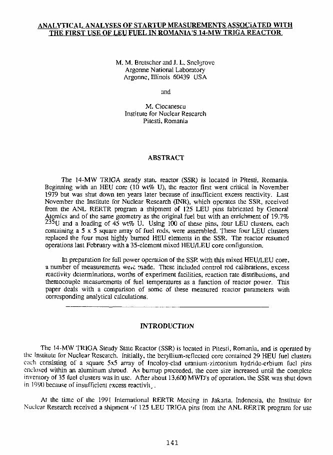
ANALYTICAL ANALYSES OF STARTUP MEASUREMENTS ASSOCIATED WITHTHE FIRST USE OF LEU FUEL IN ROMANIA'S 14-MW TRIGA REACTOR
M. M. Bretscher and J. L. SneUjroveArgonne National LaboratoryArgonne, Illinois 60439 USA
and
M. CiocanescuInstitute for Nuclear Research
Pitesti, Romania
ABSTRACT
The 14-MW TRIGA steady state reactor (SSR) is located in Pitesti, Romania.Beginning with an HEU core (10 wt% U), the reactor first went critical in November1979 but was shut down ten years later because of insufficient excess reactivity. LastNovember the Institute for Nuclear Research (INR), which operates the SSR, receivedfrom the ANL RERTR program a shipment of 125 LEU pins fabricated by GeneralAtomics and of the same geometry as the original fuel but with an enrichment of 19.7%235u and a loading of 45 wt% U. Using 100 of these pins, four LEU clusters, eachcontaining a 5 x 5 square array of fuel rods, were assembled. These four LEU clustersreplaced the four most highly burned HEU elements in the SSR. The reactor resumedoperations last February with a 35-element mixed HEU/LEU core configuration.
In preparation for full power operation of the SSR. with this mixed HEU/LEU core,a number of measurements weic made. These included control rod calibrations, excessreactivity determinations, worths of experiment facilities, reaction rate distributions, andthemocouple measurements of fuel temperatures as a function of reactor power. Thispaper deals with a comparison of some of these measured reactor parameters withcorresponding analytical calculations.
INTRODUCTION
The 14-MW TRIGA Steady State Reactor (SSR) is located in Pitesti, Romania, and is operated bythe Institute for Nuclear Research. Initially, the beryllium-reflected core contained 29 HEU fuel clusterseach consisting of a square 5x5 array of Incoloy-clad uranium-zirconium hydride-erbium fuel pinsenclosed within an aluminum shroud. As burnup proceeded, the core size increased until the completeinventory of 35 fuel clusters was in use. After about 13,600 MWD's of operation, the SSR was shut downin 1990 because of insufficient excess reactivity.
At the time of the 1991 International RERTR Meeting in Jakarta, Indonesia, the Institute forNuclear Research received a shipment 'jf 125 LEU TRIGA pins from the ANL RERTR program for use
141
in the SSR. These pins are of identical geometry as the original HEU fuel. After a detailed scries ofinspections and measurements performed by SSR personnel, tour LEU fuel clusters were assembled.
In preparation for full-power operation of the SSR with a mixed HEU/LEU core consisting of 31burned HEU and 4 fresh LEU elements, a series of measurements was undertaken last February at whichtime the ANL authors of this paper were present. This paper deals with a comparison of some of thesemeasured reactor parameters with corresponding analytical calculations.
The first set of measurements was made in'the 35-cluster HEU core shown in Fig. 1. Dased_ongamma-scanning measurements of the irradiated fuel pins together with an absolute 137Cs
standard, cluster-averaged bumups had been assigned to each fuel element. Table 1 summarizes theseresults. This tables differs somewhat from that given in Ref. [1] because of the rearrangement of someTue! pins so as to maximize the bumup of those clusters which were to be replaced with four fresh LEUfuel elements.
Experiment loops arc normally located in grid positions G7 (A Loop), D6+E6 (C'l Capsule), and E4and E9 (standard natural uranium experiments) and may be replaced with water. These loops aredescribed in Ref. [2]. The A Loop includes six zircaloy-clad CANDU type UO2 rods with 5%enrichment while the Cl Capsule is loaded with a single 5% enriched UCb rod. The standardexperiments in E4 and E9 each contain three natural uranium UO2 rods.
The methods used to determine atom densities in fresh HEU and LEU fuel as well as burnup- andaxially-dependent atom densities for the fuel described in Table 1 are discussed in detail in Rcf. [1]. Thisreference also describes the structure of the 8-group cross section sets used in this study and the modelingmethods needed for diffusion and bumup calculations.
EXCESS REACTIVITIES FOR 13 SSR CORE CONFIGURATIONSWITH FRESH HEU FUEL
It is useful to test multigroup cross sections, modeling procedures, and computational methods bycomparing calculated and measured excess reactivities for relatively simple core configurations. Theinitial approach-to-critical measurements in the SSR and the cluster-by-cluster expansion from the justcritical 17-element fresh HEU core configuration to the 29-element standard core provides a very usefulset of data for testing computational techniques. A reactivity computer was used to measure the excessreactivity of each of these 13 core configurations. The results of these measurements, including controlrod elevations at critical, are recorded in the SSR logbook [4].
The reactivity computer determines the excess reactivity by analyzing the shape of thetimc-dependent amplitude of a detector signal, proportional to the instantaneous reactor power, during asmall positive reactivity transient. Table 2 lists the kinetic parameters used by the reactivity computer(see Rcf. 3, p. 17). They are based on the properties of fresh HEU fuel. For comparison, Table 2 includesa calculated set of delayed neutron parameters for the 35-cluster core with 31 burned HEU fuel elementsand 4 fresh LEU clusters. The loading sequence for expanding the fresh core from 17 to 29 fuel clustersis shown in Fig. 2.
Table 3 summarizes the results of measured and calculated excess reactivities for each of the 13HEU core configurations. This table also shows that both measurements and calculations indicate that the16-clusler assembly is subcrilical. For these measurements all eight control rods were banked togetherand operated as a unit. Fully inserted and fully withdrawn control rods correspond to 100 and 900 unitsof withdrawal, respectively, which represents a total rod displacement equal to the height of the fuelcolumn (55.88 cm). The intermediate rod bank positions shown in Table 3 are the experimentally
142
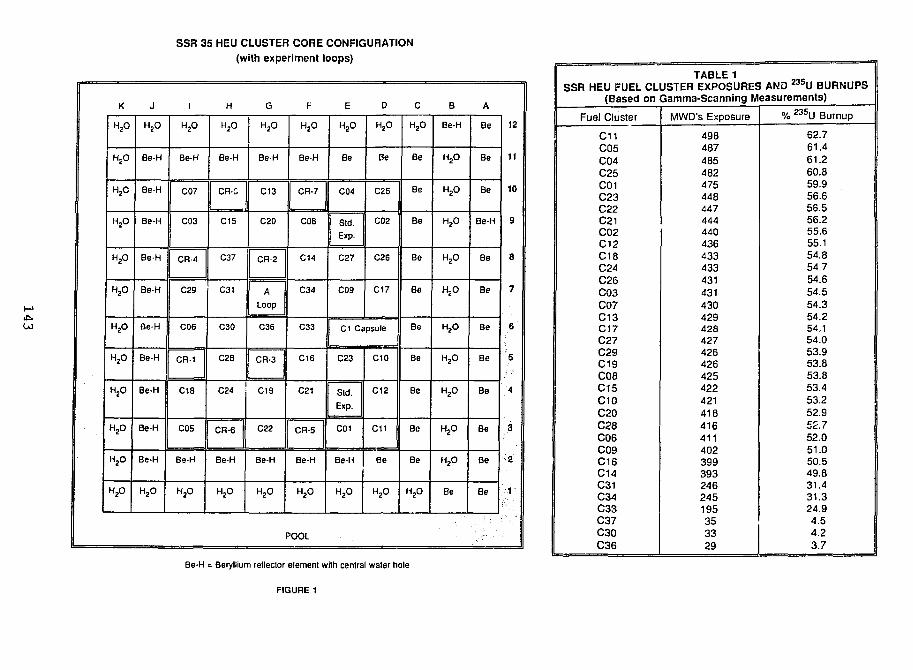
SSR 35 HEU CLUSTER CORE CONFIGURATION(with experiment loops)
K
H2O
HSO
H2O
H2O
H2O
H2O
H2O
H2O
H2O
H2O
H2O
H2O
J
H2O
Be-H
Be-H
Be-H
Be-H
Be-H
Be-H
Be-H
Be-H
Be-H
Be-H
H2O
H2O
Be-H
C07
C03
CR-4
C29
C06
CR-1
C18
C05
Be-H
H2O
H
H2O
Be-H
I CR-S
I C15
C37
C31
C30
C28
C24
CR-6
Be-H
H2O
G
HjO
Be-H
C13
C20
CR-2
ALoop
C3B
CR-3
C19
C22
Be-H
H2O
F
H2O
Be-H
CR-7
COB
C14
C34
C33
C16
C21
CR-5
Be-H
H2O
3OOL
E
H2O
Be
C04
Std.
Exp.
C27
C09
0
H2O
Be
C25
C02
C26
C17
C1 Capsule
C23
Sid.Exp.
C01
Be-H
H2O
C10
C12
C11
Be
H2O
C
H2O
Be
Be
Be
Be
Be
Be
Be
Be
Be
Be
H2O
B
Be-H
H2O
H2O
H2O
H2O
H2O
H2O
H2O
H2O
H2O
H2O
Be
A
Be
Be
Be
Be-H
Be
Be
Be
Be
Be
Be
Be
Be
12
11
10
9
8
7
6
• '5
4
3
'•Z
M •
TABLE 1SSR HEU FUEL CLUSTER EXPOSURES
(Based on
Fuel Cluster
C11C05C04C25C01C23C22C21C02C12C18C24C26C03C07C13C17C27C29C19C08C15C10C20C28C06C09C16C14C31C34C33C37C30C36
! AND 235U BURNUPSGamma-Scanning Measurements)
MWD's Exposure
498487485482475448447444440436433433431431430429428427426426425422421418416411402399393246245195353329
% 235U Burnup
62.761.461.260.859.956.656.556.255.655.154.854.754.654.554.354.254.154.053.953.853.853.453.252.952.752.051.050.549.831.431.324.94.54.23.7
Be-H = Beryllium relleclor element with central waler hole
FIGURE 1
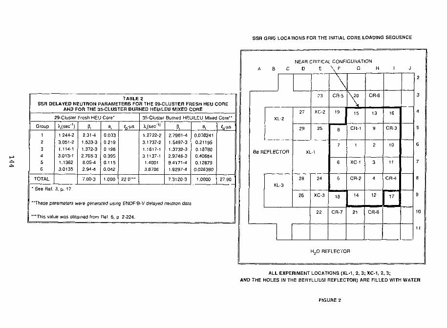
SSR GRIO LOCATIONS FOR THE INITIAL CORE LOADING SEQUENCE
TABLE 2SSR DELAYED NEUTRON PARAMETERS FOR THE 29-CLUSTER FRESH HEU CORE
AND FOR THE 35-CLUSTER BURNED HEU/LEU MIXED CORE
29-Cluster Fresh HEU Core-
Group
1
2
34
5
6
TOTAL
* See Ret.
Msec'')1.244-2
3.051-2
1.114-1
3.013-11.1362
3.0135
P,2.31-4
1.533-3
1.372-3
2.765-38.05-4
2.94-4
7.00-3
a,
0033
0.219
0 196
0.3950.1150.042
1.000 22.0'"
3, p. 17.
35-Cluster
X.fsec11
1.2722-2
3.1737-2
1.1617-1
3.1137-1
1.4001
3.8706
Burned HEU/LEU Mixed Core"
P,2.7961-4
1.5497-3
1.3732-3
2.9748-39.4171-4
1.9297-4
7.3120-3
"These parameters were generated using ENDF/B-V delayed neutron data
'"This value was obtained Irom Rel. 5. p. 2-224.
a,
0.038241
0.21195
0.18780040684
0.12879
0.026390
1.0000 27.90
A B C
NEAR CRITICAL CONFIGURATION
D E \ F G H
XL-2
Be REFLECTOR
XL-3
27
29
?3
XC-2
25
XL-1
28
26
24
XC-3
22
\
CR-5
19
8
7
6
5
18
CR-7
\ 2 0
15
CR-1
1
XC-1
CR-2
14
21
CR-6
13
9
2
3
4
12
CR-8
I
16
CR-3
10
11
CR-4
17
J
2
3
4
5
6
7
8
9
10
11
H2O REFLECTOR
ALL EXPERIMENT LOCATIONS (XL-1, 2, 3; XC-1, 2, 3;
AND THE HOLES IN THE BERYLLIUM REFLECTOR) ARE FILLED WITH WATER
FIGURE 2
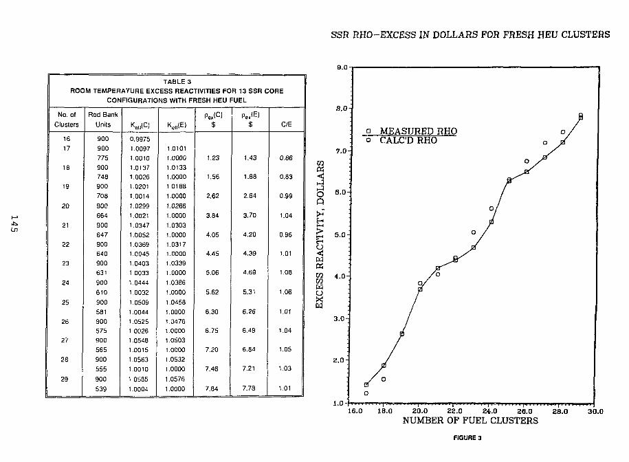
SSR RHO-EXCESS IN DOLLARS FOR FRESH HEU CLUSTERS
TABLE 3ROOM TEMPERATURE EXCESS REACTIVITIES FOR 13 SSR CORE
No. ol
Clusters
16
17
18
19
20
21
22
23
24
25
26
27
28
29
CONFIGURATIONS WITH FRESH HEU f
Rod Bank
Units
900
900
775
900748
900
708
900
664
900
647
900640
900
631
900
610
900
581
900575
900
565
900
555
900
539
•WC)0.99751.0097
1.00101.0137
1.0026
1.0201
1.0014
1.0299
1.0021
1.0347
1.0052
1.03691.0045
1.0403
1.0033
1.0444
1.0032
1.0509
1.0044
1.05251.0026
1.0548
1.0015
1.0563
1.0010
1 0585
1.0004
Kel,(E)
1.0101
1.0000
1.01331.0000
1.0188
1.0000
1.0266
1.0000
1.0303
1.0000
1.0317
1.0000
1.0339
1.0000
1.0386
1.0000
1.0458
1.0000
1.04761.0000
1.0503
1.0000
1.0532
1.0000
1.0576
1.0000
Pe*<C>$
1.23
1.56
2.62
3.84
4.05
4.45
5.06
5.62
6.30
6.75
7.20
7.46
7.84
:UEL
$
1.43
1.88
2.64
3.70
4.20
4.39
4.69
5.31
6.26
6.49
6.84
7.21
7.78
C/E
0.86
0.83
0.99
1.04
0.96
1.01
1.08
1.06
1.01
1.04
1.05
1.03
1.01
CO«
OQ
9.0
8.0
7.0
m 4.0
3.0H
2.0 H
1.0-'
a MEASURED RHOo CALC'D RHO
16.0 1B.0 20.0 22.0 24.0 26.0 28.0NUMBER OF FUEL CLUSTERS
3O.0
FIGURE 3
determined elevations for which the reactor cores arc critical. A total delayed neutron fraction of 0.0070(Table 2) was used to convert excess reactivities from absolute units to dollars and vice versa. Thecalculatcd-to-cxperiment (C/E) ratios given in Table 3 show that the analytical results arc in reasonableagreement with the measured values, which lends credence to the computational methods used in thisstudy. Note too the good agreement between the calculated value of kcff for the critical rod positions andunity. For the 13 cores at critical the average calculated eigenvalue is 1.0026 + 0.0015. Figure 3 providesa graphical display of this data.
EXCESS REACTIVITIES FOR THE SSR CORE WITH 35 BURNEDHEU FUEL CLUSTERS
The purpose of this set of measurements was to determine the reactivity worth of each of theexperiment loops relative to water as well as that for a fresh LEU fuel clement and a near-fresh HEUcluster. Figure 1 shows the core configuration used for these determinations. Before beginning thesemeasurements, the reactivity computer was used to calibrate each of the control rods. Excess reactivitieswere obtained from the observed control rod elevations at critical and the rod calibration data. Since themeasurements were made at low power (about 500 W), the analytical results arc based on cross sectionsgenerated at 296K. As before, a value of Pcff = 0.0070 was used to compare measured and calculatedexcess reactivities.
The results of these measurements are summarized in Table 4. The calculated keff's for the criticalrod positions are consistent but below unity (0.9929 ± 0.0020). Improved modeling of the experimentloops may reduce some of the C/E ratios for the excess reactivities. Particularly disturbing is the largeC/u ratio (1.48) for the case where the C36 HEU cluster (3.7% burnup) in grid location G6 was replacedwith water. The consistency of the calculated critical keff's for the three experiments involving the G6location suggests that the banked rod position is correct in each case. One suspects that the discrepancymight be due to inaccuracies in the rod calibration curves, especially near the upper ends of travel. Noerrors in the measurements or in the calculations have been identified.
EXCESS REACTIVITIES FOR THE 35-CLUSTER SSR CORE WITH FOUR FRESHLEU ELEMENTS REPLACING FOUR HIGHLY BURNED HEU ELEMENTS
In preparation for the first use of LEU fuel in the SSR, some of the HEU clusters in Fig. 1 wererelocated while all the experiment loops were removed and replaced with water. This modified coreconfiguration is shown in Fig. 4. The highly burned fuel clusters C25, C01, Cl l , and C05 (see Table 1)were replaced, one at a time, with the fresh LEU clusters C42, C40, C38, and C39, respectively. Witheach fuel cluster replacement the control rod bank elevation at critical was determined. With the fourLEU clusters in place at the end of these measurements, the control rods were recalibrated again makinguse of the reactivity computer. This calibration data was used to evaluate the measured excessreactivities. Later, the Cl Capsule was placed in grid positions D6+E6, the standard natural uraniumexperiments in E4 and E9, and a 5x5 stainless steel (SS) shim bundle in G7.
Table 5 summarizes the results of these measurements and the corresponding calculations. Exceptfor the first case, measured and calculated excess reactivities are in good agreement. As in the lastsection, all these measurements were carried out at low power and so the analytical results are based on2%K cross sections. Also, a value of Pcff = 0.0070 was used.
146

SSR 35 HEU CLUSTER CORE CONFIGURATIONBEFORE THE ADDITJON OF FOUR FRESH LEU ELEMENTS
EXCESS REACTIVITIES
Deviation Irom Fig. 1 Core
None
G6: C36-»H2O
G6: C36-tC38 (LEU)
D6+E6:C1-»H2O
G7: A Loop-»H2O
G7: A Loop-»H20
D6+E6:C1->H2O
E4, E9: Std Exp's->H2O
G7: A Loop-tHzO
D6<-E6:Ci-tH2O
Rod
Bank
Units
900545
900
728
900
517
900
568
900
588
900
600
900
612
TABLE 4
FOR THE SSR FIGURE 1 CORES
Kell(C)
1.03885
0.99240
1.008B00.99187
1.04360
0.99256
1.03442
0.98994
1.03214
0.99547
1.03114
0.99538
1.02756
0.99281
1.04570
1.00000
1.011531.00000
1.05226
1.00000
1.04045
1.00000
1.03606
1.00000
1.03349
1.00000
1.031011.00000
Pex(C)$
6.436
2.417
7.039
6.205
5.098
4.997
4.8C5
Pe.(E)$
6.243
1.629
7.095
5.554
4.972
4.629
4.297
C/E
1.03
1.48
0.99
1.12
1.03
1.08
1.13
1 .H20
H20
H20
H2O
H2O
H2O
H20
H2O
H2O
H2O
H2O
H2O
J
H2O
Be-H
Be-H
Be-H
Be-H
Be-H
Be-H
BB-H
Be-H
Be-H
Be-H
H2O
1
H2O
Be-H
CD2
C19
CR-4
C11
C05
CR-1
C21
C22
Be-H
H2O
H
H,0
Be-H
CR-8
C24
C37
C31
C30
C29
C17
CR-6
Be-H
H2O
G
H2O
Be-H
C15
C28
CR-2
H2O
C36
CR-3
C15
C04
BeH
H2O
F
H2O
Be-H
CR-7
C06
C25
C34
C33
C01
C14
CR-5
Be-H
H2O
POOL
E D
H2O
Be
CIS
C09
C23
H2O
Be
C07
C12
C2C
CIO
H2O
C27
H2O
C03
Be-H
H2O
COB
C26
C13
Be
H2O
C
H2O
Be
Be
Be
Be
Be
Be
Be
Be
Be
Be
H2O
B
Be-H
H2O
H2O
H2O
H2O
H2O
H2O
H2O
H2O
H2O
H2O
Be
A
Be
Be
Be
Be-H
Be
Be
Be
Be
Ce
Be
Be
Be
12
11
10
9
B
7
6
5
4
3
2
1
Be-H « Beryllium reflector elerrrnl wilh central waier hole
FIGURE 4
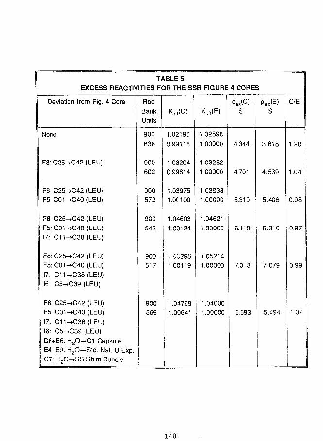
TABLE 5EXCESS REACTIVITIES FOR THE SSR FIGURE
Deviation from Fig. 4 Core
None
F8: C25-4C42 (LEU)
F8: C25->C42 (LEU)F5-C01-»C40 (LEU)
F8: C25->C42 (LEU)F5:C01-*C40 (LEU)17: C11-*C38 (LEU)
F8: C25->C42 (LEU)F5:C01->C40 (LEU)17: C11->C38 (LEU)16: C5->C39 (LEU)
F8: C25-+C42 (LEU)F5:C01->C40 (LEU)17: C11->C38 (LEU)16: C5->C39 (LEU)D6+E6: H2O->C1 CapsuleE4, E9: H2O-»Std. Nat. U Exp.G7: H2O-*SS Shim Bundle
RodBankUnits
900
636
900602
900
572
900
542
900517
900569
Keff(C)
1.021960.99116
1.032040.99814
1.039751.00100
1.046031.00124
1.052981.00119
1.047691.00641
Keff(E)
1.02598
1.00000
1.032821.00000
1.03S331.00000
1.04621
1.00000
1.05214
1.00000
1.040001.00000
4 CORES
Pex(C)$
4.344
4.701
5.319
6.110
7.018
5.593
Pex(E)$
3.618
4.539
5.406
6.310
7.079
5.494
C/E
1.20
1.04
0.98
0.97
0.99
1.02
148
INTEGRAL CONTROL ROD WORTHS FOR THE SSR 35-CLUSTER COREWITH FOUR FRESH LEU FUEL ELEMENTS
This cc x configuration is shown in Fig. 4 but with the highly burned HEU fuel clusters in gridlocations F5, t \ 16, and 17 replaced with fresh LEU fuel elements. Each control rod was calibrated usingthe reactivity computer [3] to measure the reactivity worth associated with small outward displacementsof the control rod assembly. Measurements covered the full range of control rod motion from the fullyinserted to the fully withdrawn position. The integral worth is the sum of the measured worths for eachsegment of rod withdrawal.
SSR control rod assemblies consist of an upper poison section and a lower aluminum followersection. The poison section (Ref. 5, p. 2-127) consists c f a 58.42 cm stack of pressed B4C (natural boron)pellets in the form of a square annulus with water at the center. For some initial diffusion calculations thepoison section of the control rod was represented by a set of group-dependent internal boundaryconditions (current-to-flux ratios) applied at the surface of the B4C absorber and calculated by themethods described in Ref. [6]. It was soon learned, however, that nearly the same results for control rodworths are obtained by using normal diffusion theory with cross sections homogenized over the entiiccontrol rod cell. This more approximate method has the advantage of significantly reducing the numberof mesh intervals needed. Use of the internal boundary conditions increases the calculated rod worth byabout 0.3%.
The output from the reactivity computer is based on the delayed neutron parameters for fresh HEUfuel shown in Table 2. Probably a better set of parameters for this particular core is the second set alsolisted in Table 2. An estimate of the reactivity computer's response based on this second set of parametersresulted in a correction which tends to reduce the experimental results by about 1% or less. Because ofuncertainties in this calculation, this small correction was not applied to the experimental data.
Table 6 compares the measured and calculated integral control rod worths. The calculations arebased on the eigenvalues obtained for the fully withdrawn rod (900 units) and the fully inserted rod (100units). For these calculations the remaining 7 rods are banked together and withdrawn to the positionwhere the reactor was observed to be critical for the the rod in question located at its mid withdrawalpoint (500 units). As before, a value of (3^ = 0.0070 (Table 2) was used to convert absolute worths todollars.
Table 6 shows that the calculations and measurements are in satisfactory agreement for therelatively high worth rods (rods 1-4), but that the low worth rods (5-8) are significantly under-calculated.These low worth rods are located adjacent to thf; beryllium reflector and perhaps a different set of crosssections are needed for the evaluation of their worths. Since eigenvalue changes of only about 0.0004would bring these calculated results into reasonable harmony with the measurements, the diffusioncalculations require the eigenvalues to converge to within 1.0E-5. Figure 5 displays these results byshowing the C/E ratio for each control rod and the % 235TJ burnup for each fuel cluster.
CONCLUSION
The 14-MW TRIGA research reactor in Pitesti, Romania, was shut down in 1990 because the fuelwas too highly burned to continue operations. Last November they received a shipment of 125unirradiated LEU fuel pins from the ANL RERTR program. After a number of preliminarymeasurements, the SSR resumed operations last February with a mixed 31 HEU/4 LEU core. Ourcalculations indicate that the SSR should be able to operate for about 2450 MWD's with this coreconfiguration. Based on current operating schedules, this will allow the SSR to continue running until
1 4 9
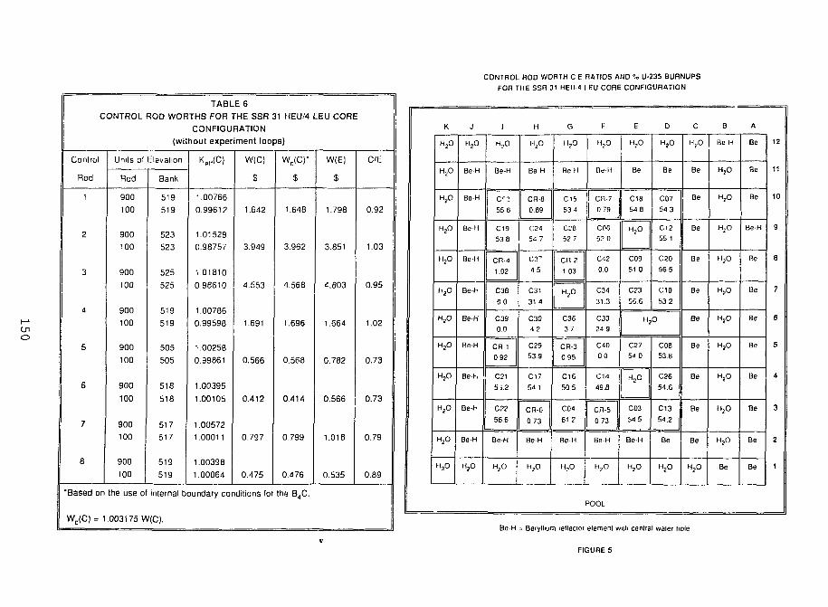
CONTROL ROD WORTH C E RATIOS AND % U-235 BURNUPS
FOR THE SSR 31 HEU'4 LEU CORE CONFIGURATION
TABLE 6CONTROL ROD WORTHS FOR THE SSR 31 HEU/4
Control
Rod
1
2
3
4
5
6
7
8
•Based on
WC(C) = 1
(wii
Units ol Elevation
Rod
900
100
900
100
900
100
900
100
900
100
900
100
900
100
900
too
Bank
519
519
523
523
525
525
519
519
505
505
518
518
517
517
519
519
CONFIGURATIONhoul experiment loops)
1.00766
0.99612
1.01529
0.98757
1.01810
0.98610
1.00786
0.99598
1.00258
0.99861
1.00395
1.00105
1.005721.00011
1.00398
1.00064
W(C)
s
1.642
3.949
4.553
1.691
0.566
0.412
0.797
0.475
the use of internal boundary conditions for
.003175 W(C).
WC(C)-
$
1.648
3.962
4.568
1.696
0.568
0.414
0799
0.476
the B4C,
-EU CORE
W(E)
$
1.798
3.851
4.803
1.664
0.782
0.566
1.018
0.535
C/E
0.92
1.03
0.95
1.02
0.73
0.73
0.79
0.89
K
'fa
H20
H20
H2O
"fa
H20
H20
H20
H20
H20
H j O
H2O
J
H2O
BeH
Be-H
BeH
Be-H
Be-H
Be-H
Be-H
Be-h
Be-H
Be-H
H2O
1
H,0
Be-H
55 6
C1953 8
CR 4
1.02
C38
00
C390.0
CR-1
0 92
C21
5i.2
C22
56.6
Be-H
H2O
H
H2O
Be H
CR-8
0.69
C24
54 7
1 5
C31
31 4
C304 2
C29
53 9
C17
54 1
CR-6
0.73
Be-H
H j O
G
H,0
Be H
C1553 4
C M52 7
cn 21 03
H2O
C3637
CR-3
0 95
C16
50 5
C04
61 2
Be-H
H,0
F
H,0
Be-H
CR-7
0 79
COB52 0
0 0
C31
31 3
C3324 9
C4000
C14
49.B
CR-5 I
0 73
Be-H
H?O I
3OOL
E
H-,0
Be
C1854.8
H 2 O
C09
51 0
C23
56.6
"2
C27
54 0
H2O
i 1
C03
54 5
Be-H
H,O
D
o
Be
C07
54 3
C1255 1
C20
56 5
C10
53.2
O
C08
538
C26
54.6
C13
54.2
Be
H j O
C
H?O
Be
Be
Be
Be
Be
Be
Be
Be
Be
Be
H?O
B
Be-H
o
H j O
H,0
H j O
H2O
H j O
H2O
H j O
"fa
H j O
Be
A
Be
Be
Be
BeH
Be
Be
Be
Be
Be
Be
Be
Be
12
11
10
9
S
7
6
5
4
3
2
1
Be-H = Beryllium retleclor element wilh central waler hole
FIGURE 5
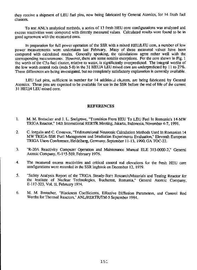
they receive a shipment of LEU fuel pins, now being fabricated by General Atomics, for 14 fresh fuelclusters.
To test ANL's analytical methods, a series of 13 fresh HEU core configurations was analyzed andexcess reactivities were compared with directly measured values. Calculated results were found to be ingood agreement with the measured ones.
In preparation for full power operation of the SSR with a mixed HEU/LEU core, a number of lowpower measurements were undertaken last February. Many of these measured values have beencompared with calculated results. Generally speaking, the calculations agree rather well with thecorresponding measurements. However, there are some notable exceptions. For the core shown in Fig. 1the worth of the C36 fuel cluster, relative to water, is significantly overpredicted. The integral worths ofthe low worth control rods (rods 5-8) in the 31 HEU/4 LEU mixed core are underpredicted by 11 to 27%.These differences are being investigated, but no completely satisfactory explanation is currently available
LEU fuel pins, sufficient in number for 14 additional clusters, are being fabricated by GeneralAtomics. These pins are expected to be available for use in the SSR before the end of life of die current31 HEU/4 LEU mixed core.
REFERENCES
1. M. M. Bretscher and J. L. Snelgrove, "Transition From HEU To LEU Fuel In Romania's 14-MWTRIGA Reactor," 14th International RERTR Meeting, Jakarta, Indonesia, November 4-7,1991.
2. C. Iorgulis and C. Costescu, "Tridimensional Neutronic Calculation Methods Used In Romanian 14MW TRIGA-SSR Fuel Management and Irradiation Experiments Evaluation," Eleventh EuropeanTRIGA Users Conference, Heidelberg, Germany, September 11-13,1990, GA TOC-22.
3. "R-20A Reactivity Computer Operation and Maintenance Manual ELE 313-0000-2," GeneralAtomic Company, E-l 15-569, February 1976.
4. The measured excess reactivities and critical control rod elevations for the fresh HEU coreconfigurations were recorded in the SSR logbook on December 12, 1979.
5. "Safety Analysis Report of the TRIGA Steady-Stare Research/Materials and Testing Reactor forthe Institute of Nuclear Technologies, Bucharest, Romania," General Atomic Company,E-l 17-323, Vol. II, February 1974.
6. M. M. Bretscher, "Blackness Coefficients, Effective Diffusion Parameters, and Control RodWorths for Thermal Reactors," ANL/RERTR/TM-5 September 1984.
151
MEASUREMENTS AND COMPUTATIONS FOR NEUTRON FLUX IN THEROM. kNIAN TRIGA STEADY STATE REACTOR HEU CORE WITH FOUR
EXPERIMENTAL LEU FUEL CLUSTERS
by
Constantin Toma, Dumitru Barbos, Marin Ciocanescu, and Petre Busuioc
Institute for Nuclear ResearchPitesti, Romania
William Whittemore
General AtomicsSan Diego, California, U.S.A.
James Snelgrove
Argonne National LaboratoryArgonne, Illinois, U.S.A.
ABSTRACT
The four HEU fuel clusters with the highest 235U burnups were removedfrom the highly burned I4-MW steady state Romanian TRIGA reactor andreplaced with four fresh LEU fuel clusters. The fuel rods in these new clusterscontained 45 wt% uranium enriched to about 19.75% 235U with erbium as aburnable poison.
A series of measurements was conducted to characterize the neutronicbehavior of the new core configuration and to compare with calculatedparameters. The neutron flux level and spectrum were measured in an in-coreexperimental region using the method of activated foils and the SAND IIcomputer code. Additionally, the silver reaction rate distribution was determinedusing self-powered neutron detectors positioned in a number of fuel rod locations.
Separate measurements were made for the gamma rays from the 235Udistributed in 15 of the unirradiated fuel rods. The results of careful axialgamma-ray scans of the rods yielded results in agreement with manufacturingrecords for the 235U distribution.
The operational experience for the new core configuration includingreactivity values and fuel temperatures will be reported in other papers.
152
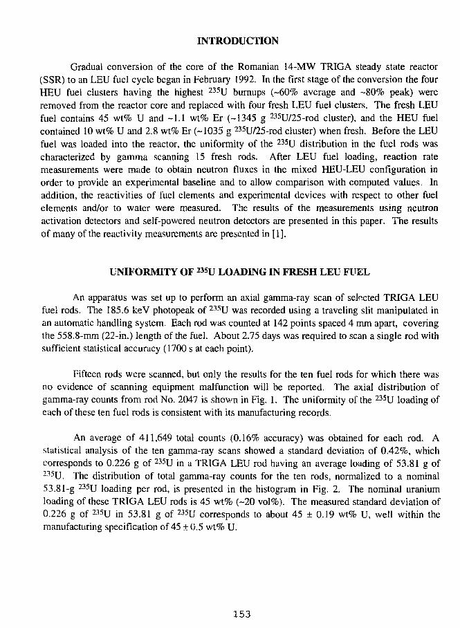
INTRODUCTION
Gradual conversion of the core of the Romanian 14-MW TRIGA steady state reactor(SSR) to an LEU fuel cycle began in February 1992. In the first stage of the conversion the fourHEU fuel clusters having the highest 235U burnups (-60% average and ~80% peak) wereremoved from the reactor core and replaced with four fresh LEU fuel clusters. The fresh LEUfuel contains 45 wt% U and -1.1 wt% Er (-1345 g 235U/25-rod cluster), and the HEU fuelcontained 10 wt% U and 2.8 wt% Er (-1035 g 235U/25-rod cluster) when fresh. Before the LEUfuel was loaded into the reactor, the uniformity of the 235U distribution in the fuel rods wascharacterized by gamma scanning 15 fresh rods. After LEU fuel loading, reaction ratemeasurements were made to obtain neutron fluxes in the mixed HEU-LEU configuration inorder to provide an experimental baseline and to allow comparison with computed values. Inaddition, the reactivities of fuel elements and experimental devices with respect to other fuelelements and/or to water were measured. The results of the measurements using neutronactivation detectors and self-powered neutron detectors are presented in this paper. The resultsof many of the reactivity measurements are presented in [1].
UNIFORMITY OF 23SU LOADING IN FRESH LEU FUEL
An apparatus was set up to perform an axial gamma-ray scan of selected TRIGA LEUfuel rods. The 185.6 keV photopeak of 235U was recorded using a traveling slit manipulated inan automatic handling system. Each rod was counted at 142 points spaced 4 mm apart, coveringthe 558.8-mm (22-in.) length of the fuel. About 2.75 days was required to scan a single rod withsufficient statistical accuracy (1700 s at each point).
Fifteen rods were scanned, but only the results for the ten fuel rods for which there wasno evidence of scanning equipment malfunction will be reported. The axial distribution ofgamma-ray counts from rod No. 2047 is shown in Fig. 1. The uniformity of the 235U loading ofeach of these ten fuel rods is consistent with its manufacturing records.
An average of 411,649 total counts (0.16% accuracy) was obtained for each rod. Astatistical analysis of the ten gamma-ray scans showed a standard deviation of 0.42%, whichcorresponds to 0.226 g of 235U in a TRIGA LEU rod having an average loading of 53.81 g of235U. The distribution of total gamma-ray counts for the ten rods, normalized to a nominal53.81-g 235U loading per rod, is presented in the histogram in Fig. 2. The nominal uraniumloading of these TRIGA LEU rods is 45 wt% (-20 vol%). The measured standard deviation of0.226 g of 235U in 53.81 g of 235U corresponds to about 45 ± 0.19 wt% U, well within themanufacturing specification of 45 + 0.5 wt% U.
153
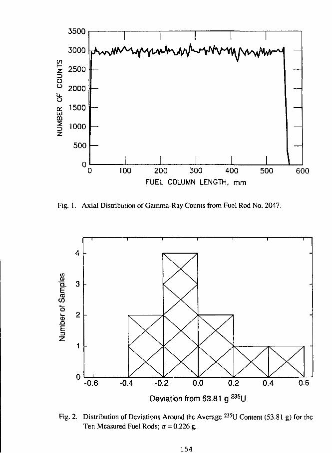
3500
100 200 300 400
FUEL COLUMN LENGTH, mm
500 600
Fig. 1. Axial Distribution of Gamma-Ray Counts from Fuel Rod No. 2047.
E=3
4 -
enCDQ. 3COCO
0 .
1 -
0
1 1
-
1
XX
XXX X X
1
X
-
-0.6 -0.4 -0.2 0.0 0.2 0.4
Deviation from 53.81 g 235U
0.6
Fig. 2. Distribution of Deviations Around the Average 235U Content (53.81 g) for theTen Measured Fuel Rods; o = 0.226 g.
154
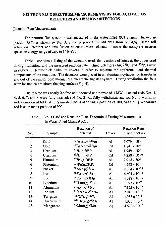
NEUTRON FLUX SPECTRUM MEASUREMENTS BY FOIL ACTIVATIONDETECTORS AND FISSION DETECTORS
Reaction Rate Measurements
The neutron flux spectrum was measured in the water-filled XCl channel, iocated inposition G-7, as shown in Fig. 3, utilizing procedures and data from [2,3,4,5]. Nine foilactivation detectors and two fission detectors were selected to cover the complete neutronspectrum energy range of zero to 14 MeV.
Table 1 contains a listing of the detectors used, the reactions of interest, the cover usedduring irradiation, and the measured reaction rate. Three detectors (Au, 235U, and 239Pu) wereirradiated in 1-mm-thick cadmium covers in order to separate the epithermal and thermalcomponents of the reactions. The detectors were placed in an aluminum cylinder for transfer inand out of the reactor core through the pneumatic transfer system. During irradiation the foilswere located 28 cm above the plug surface (Fig. 4).
The reactor was nearly Xe-free and operated at a power of 3 MW. Control rods Nos. 1,4_ 5, 6, 7, and 8 were fully inserted; rod No. 2 was fully withdrawn; and rod No. 3 was at anindex position of 690. A fully inserted rod is at an index position of 100, and a fully withdrawnrod is at an index position of 900.
Table 1. Foils Used and Reaction Rates Determined During Measurementsin Water-Filled Channel XCl
No.
123456789
101112131415
Sample
GoldGoldUraniumUraniumPlutoniumPlutoniumNickelIronIronLutetiumAluminumIndiumTungstenDysprosiumManganese
Reaction ofInterest
l97Au(n,Y)i98Au197Au(n,Y)198Au235U(n,f)F.P.235U(n,f)F.P.239Pu(n,f)F.P.239Pu(n,f)F.P.58Ni(n,p)58Co58Fe(n,Y)59Fe54Fe(n,p)54MnI76Lu(n,y)!77Lu27Al(n,a)24Nall5In(n,n')115mlnI86w(n,y)i87w'•64Dy(n,y)i65Dy55Mn(n,Y)56Mn
Cover
AlCdAlCdAlCdAlAlAlAlAlAlAlAlAl
Reaction Rate(disint./nucl.-s)
5.079 x 10⁻⁹
1.841 x 10⁻⁹
1.949 xlO-8
4.250 x 10-102.914xl0-8
4.598 x 10⁻¹°9.654 x IO-13
4.605x10-114.028 x 10-121.397 x 10⁻⁷
7.155x10-152.045 x IO-121.953x10-91.035 xlO-7
4.570x10⁻¹°
155
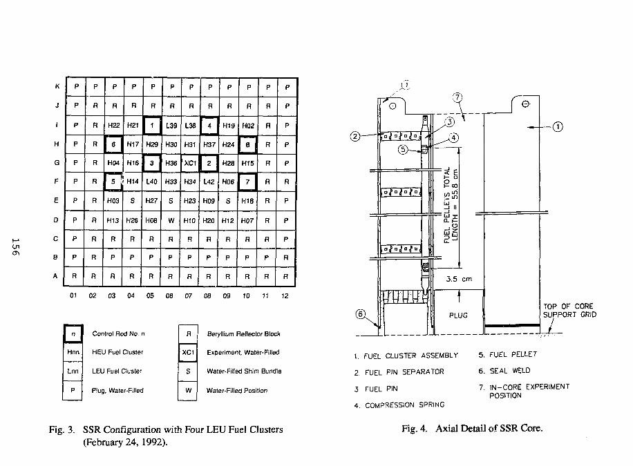
K
J
1
H
G
F
UJ
D
C
B
A
P
P
P
P
P
P
P
P
P
P
R
P
R
R
R
R
R
R
R
R
R
R
P
R
H22
6
H04
5
H03
H13
R
P
R
P
R
H21
H17
H16
H14
S
H26
R
P
R
R
1
H29
3
L40
H27
H08
R
P
R
R
L39
H30— • —^
H 3 6
H33
S
w
R
p
R
R
L38
H31
• ^ ^ - >X C 1
H34
H23
H10
R
P
R
R
4
H37• •MB
2
L42
H09
H20
R
P
R
R
H19
H24
H28
H06
S
H12
R
P
R
P
R
H02
8
H15
7
H18
H07
R
P
R
P
R
R
R
R
R
R
R
R
P
R
P
P
P
P
P
R
P
P
P
R
R
01 02 03 04 05 06 07 08 09 10 11 12
n
Hnn
Lnn
P
Control Rod No. n
HEU Fuel Cluster
LEU Fuel Cluster
Plug, Water-Filled
R
XC1
S
W
Beryllium Reflector Block
Experiment, Water-Filled
Water-Filled Shim Bundle
Water-Filled Position
Fig. 3. SSR Configuration with Four LEU Fuel Clusters(February 24, 1992).
(i
(7)o
©—1
o f o f a f a |
• 2 12
-LJ
, o
3.5 cm
PLUG
0
TOP OF CORESUPPORT GRID
1. FUEL CLUSTER ASSEMBLY
2. FUEL PIN SEPARATOR
3. FUEL PIN
4. COMPRESSION SPRING
5. FUEL PELLET
6. SEAL WELD
7. IN-CORE EXPERIMENTPOSITION
Fig. 4. Axial Detail of SSR Core.
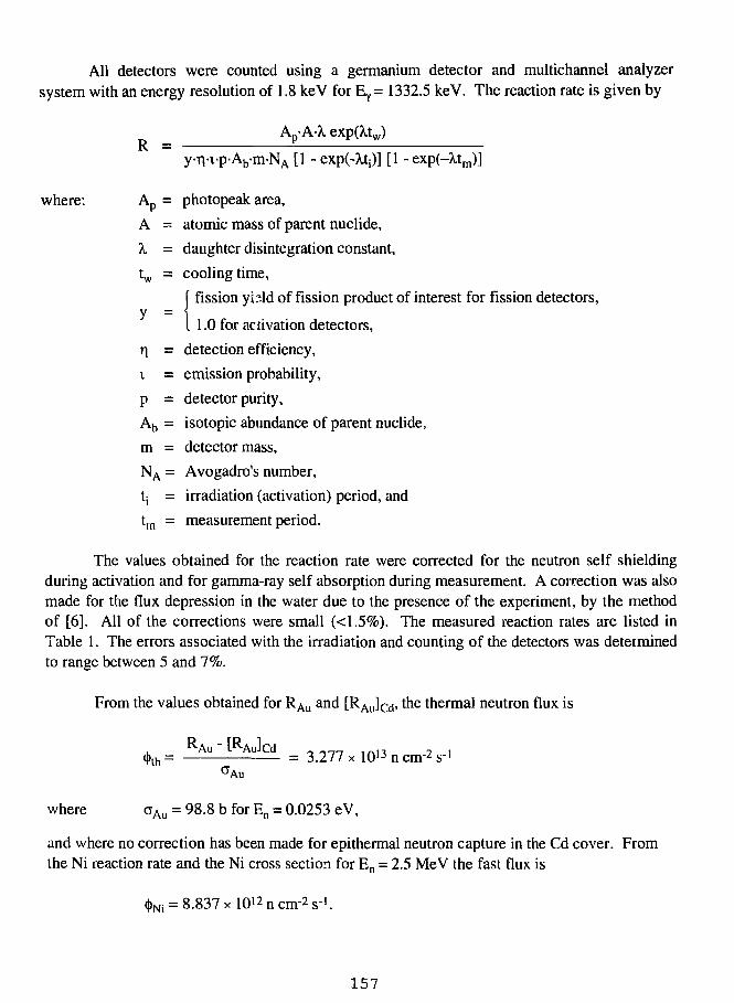
All detectors were counted using a germanium detector and multichannel analyzersystem with an energy resolution of 1.8 keV for EY = 1332.5 keV. The reaction rate is given by
AD-A-k exp(A,tw)R =
y-ri-i-p-Ab-m-NA [1 - exp(-Xtj)] [1 - exp(-Xtm)]
where: Ap = photopeak area,
A = atomic mass of parent nuclide,
X = daughter disintegration constant,
tw = cooling time,
[ fission yi?ld of fission product of interest for fission detectors,
y = iI 1.0 for activation detectors,
ri = detection efficiency,
i = emission probability,
p = detector purity,
Ab = isotopic abundance of parent nuclide,
m = detector mass,
NA = Avogadro's number,
tj = irradiation (activation) period, and
tm = measurement period.The values obtained for the reaction rate were corrected for the neutron self shielding
during activation and for gamma-ray self absorption during measurement. A correction was alsomade for the flux depression in the water due to the presence of the experiment, by the methodof [6]. All of the corrections were small (<1.5%). The measured reaction rates are listed inTable 1. The errors associated with the irradiation and counting of the detectors was determinedto range between 5 and 7%.
From the values obtained for RAu and [RAJcd' t n e thermal neutron flux is
, Au[Aulcd , -__ 1A., , .(j)th= = 3.277 x 10¹³ n cm-2 s"'
°Au
where oAu = 98.8 b for En = 0.0253 eV,
and where no correction has been made for epithermal neutron capture in the Cd cover. Fromthe Ni reaction rate and the Ni cross section for En = 2.5 MeV the fast flux is
<|>Ni = 8.837xl0i2ncm-2s-1.
157
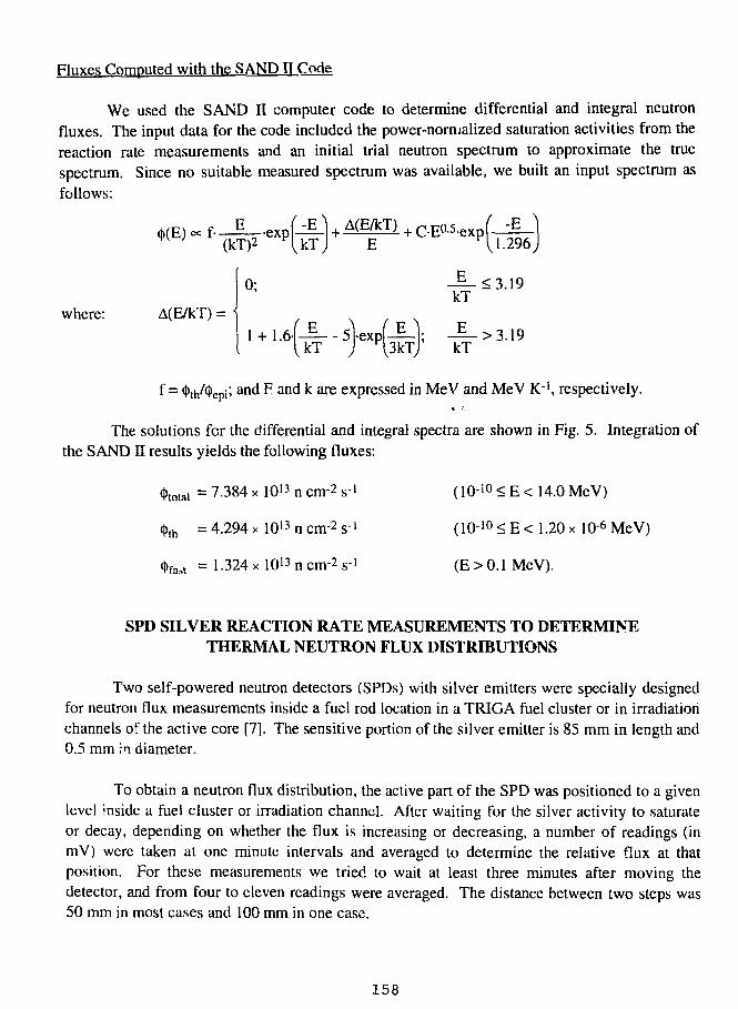
Fluxes Computed with the SAND II Code
We used the SAND II computer code to determine differential and integral neutronfluxes. The input data for the code included the power-normalized saturation activities from thereaction rate measurements and an initial trial neutron spectrum to approximate the truespectrum. Since no suitable measured spectrum was available, we built an input spectrum asfollows:
A ( E / k T ) +C-EQ-5-expf-gE I 1 - 2 9
where: A(E/kT) = '
296
0; JL<3.19kT
1 + i .6.(JL . sjexppU; - i - > 3.19kT j F 3 k T kT
f = ^h/^epi; and F and k are expressed in MeV and MeV K"1, respectively.
The solutions for the differential and integral spectra are shown in Fig. 5. Integration ofthe SAND II results yields the following fluxes:
(t>total = 7.384 x 10" n cm-2 s-' (101 0 < E < 14.0 MeV)
4>lh = 4.294 x 101 3ncnr2s- ' ( 1 0 1 0 < E < 1.20 x 10⁶ MeV)
<|>fait = 1.324 xlO'^n cm-2 s-1 (E> 0.1 MeV).
SPD SILVER REACTION RATE MEASUREMENTS TO DETERMINETHERMAL NEUTRON FLUX DISTRIBUTIONS
Two self-powered neutron detectors (SPDs) with silver emitters were specially designedfor neutron flux measurements inside a fuel rod location in a TRIGA fuel cluster or in irradiationchannels of the active core [7]. The sensitive portion of the silver emitter is 85 mm in length and0.5 mm in diameter.
To obtain a neutron flux distribution, the active part of the SPD was positioned to a givenlevel inside a fuel cluster or irradiation channel. After waiting for the silver activity to saturateor decay, depending on whether the flux is increasing or decreasing, a number of readings (inmV) were taken at one minute intervals and averaged to determine the relative flux at thatposition. For these measurements we tried to wait at least three minutes after moving thedetector, and from four to eleven readings were averaged. The distance between two steps was50 mm in most cases and 100 mm in one case.
158
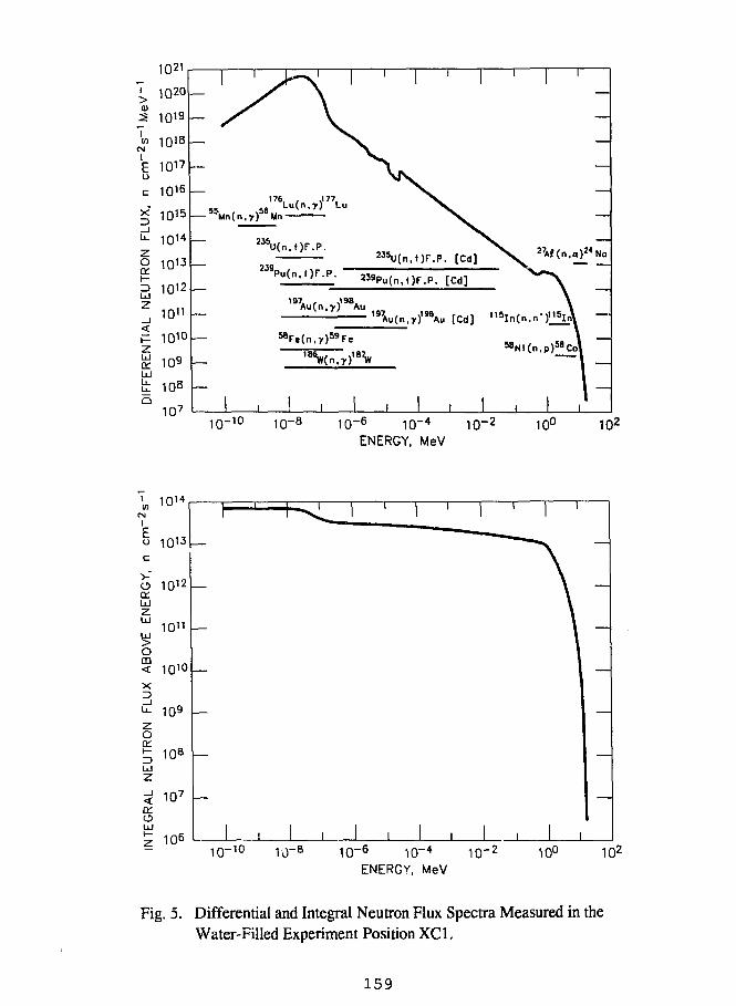
IW
CMIEu
1021
1020
1019
1018
1017
1Q16
OQ:
LLJ
z
Ida:
1014 —
1012
ion
101°
109
108
107
— s
— 55Mn(n
—
—
5 6 '7 6Lu(o.
W 5U(n,t )F
239
5BFe(n
V.177,
. p .
LL
.T)59F«
1
2MU(n.
s)F.P
239Pu(n,f)F.P.
187
1 ,
)'MAu
|
1
[Cd]
[Cd]
[Cd]
1
1
58Ni(n,f
1 ,
—
——
I —
10-10 1 0 -8 1 0 - 6 1 0 -4 1 0 - 2 100 1O2
ENERGY, MeV
10- 1 0 10~6 10~4 10~2
ENERGY, MeV
10° 102
Fig. 5. Differential and Integral Neutron Flux Spectra Measured in theWater-Filled Experiment Position XCl.
159
At the lowest possible level for the detector in a fuel rod location within a fuel cluster, themiddle of the silver emitter was located 50 mm above the bottom of the lowest fuel pellet. Atthe lowest position of the SPD in the experimental location XC 1 with a plug at the bottom, themiddle of the silver emitter was located 20 mm above the bottom of the lowest fuel pellet.
After equilibrium is achieved, the SPD output is proportional to the neutron absorptionrate in the silver emitter, which is, of course, proportional to the neutron flux. Although neutronabsorption in silver is predominantly in the thermal range, silver does have a substantialepithermal resonance. Therefore, a reaction rate distribution measured with the SPD is equal tothe distribution of thermal flux only if the flux spectrum is the same at every measurement point.This is generally a good approximation for axial measurements taken within the fuel columnheight at a given grid position. However, the flux spectrum might vary axially close to partiallyinserted control rods. Flux spectra are also expected to be very similar near the centers of well-moderated regions, such as water-filled (empty) experiment positions, so detector responses forthese regions would represent relative thermal fluxes. However, careful calibrations must beperformed before comparisons of thermal fluxes in regions of differing flux spectra (forexample, between the center and the edge of an irradiation channel) can be made.
The raw data are given in Table 2, and axial profiles (using power-normalized data) arepresented in Figs. 6 and 7. Axial profiles for two different positions of the control rods arecompared in the first two figures, highlighting the perturbation effect of the control rod positionson the flux distribution. The axial peak-to-average factor is shown for each curve. The diagramswith the plots show the locations of the SPDs. It should be noted that positions with empty fuelclusters or with plugs are essentially water-filled. In the measurement in the fuel cluster withshims, stainless steel dummy fuel rods filled the 23 positions not occupied by the SPDs.
REFERENCES
1. M. M. Bretscher, J. L. Snelgrove, and M. Ciocanescu, "Analytical Analyses of StartupMeasurements Associated with the First Use of LEU Fuel in Romania's 14-MW TRIG AReactor," these proceedings.
2. I. Garlea, C. Miron, T. Musat, and C. Roth, "Proposed Procedures for Flux Measurements inthe Romanian TRIGA Reactor," Pitesti (1978).
3. W. N. McElroy, S. Berg, and G. Gigas, "Neutron-Flux Spectral Determination by FoilActivation," Nucl. Sci. Eng. 27, 533-541 (1967).
4. Al. Berinde, Reactor Physics. Bucharest (1970).
5. International Atomic Energy Agency, Handbook on Nuclear Activation Data. TechnicalReport Series No. 273, Vienna (1987).
160
6. W. Bothe, "Zur Methodik der Neutronensonden," Z. fur Physik 120, 437-449 (1943).
7. R. Baudry, "Mesure continue des flux de neutrons thermiqes par sonde a emetteur p,"Commisariat a 1'Energie Atomique Report CEA-R-4312/1972.
161
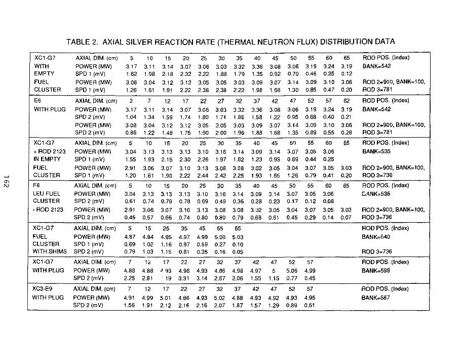
TABLE 2. AXIAL SILVER REACTION RATE (THERMAL NEUTRON FLUX) DISTRIBUTION DATA
XC1-G7
WITHEMPTY
FUELCLUSTER
E6WITH PLUG
XC1-G7
+ ROD 2123IN EMPTY
FUELCLUSTER
F8LEU FUELCLUSTER
- ROD 2123
XC1-G7
FUELCLUSTERWITH SHIMS
XC1-G7
WITH PLUG
XC3-E9
WITH PLUG
AXIAL DIM. (cm)
POWER (MW)SPD 1 (mV)
POWER (MW)SPD 1 (mV)
AXIAL DIM. (cm)
POWER (MW)SPD 2 (mV)
POWER (MW)SPD2(mV)
AXIAL DIM. (cm)
POWER (MW)SPD 1 (mV)
POWER (MW)SPD 1 (mV)
AXIAL DIM. (cm)
POWER (MW)SPD 2 (mV)
POWER (MW)SPD 2 (mV)
AXIAL DIM. (cm)
POWER (MW)SPD 1 (mV)SPD 2 (mV)
AXIAL DIM. (cm)
POWER (MW)SPD 2 (mV)
AXIAL DIM. (cm)
POWER (MW)SPD 2 (mV)
5
3.171.62
3.081.26
23.171.04
3.080.86
5
3.041.55
2.911.20
5
3.040.61
2.910.45
5
4.870.690.79
7
4.882.25
7
4.911.56
10
3.111.98
3.041.61
73.111.34
3.041.22
10
3.131.93
3.061.61
10
3.130.74
3.060.57
154.841.021.03
12
4.882.81
12
4.991.91
15
3.142.18
3.12
1.91
12
3.141.59
3.121.48
15
3.132.15
3.071.90
15
3.130.79
3.070.66
254.851.161.15
17
^93; 19
17
5.012.12
203.072.32
3.122.22
17
3.071.74
3.121.75
20
3.132.30
3.102.22
20
3.130.78
3.100.74
35
4.970.970.81
22
4.963.31
22
4.862.16
25
3.062.22
3.052.38
223.061.80
3.051.90
25
3.102.26
3.132.44
25
3.100.69
3.130.80
454.990.590.35
27
4.933.14
27
4.932.16
30
3.031.88
3.052.38
27
3.031.71
3.052.00
30
3.161.97
3.082.42
30
3.160.49
3.080.80
55
5.000.270.16
32
4.862.67
32
5.022.07
35
3.321.79
3.032.22
323.321.86
3.031.96
35
3.141.623.082.25
35
3.140.36
3.080.79
655.030.100.05
374.982.06
37
4.881.87
40
3.361.35
3.091.98
37
3.361.58
3.091.88
40
3.091.23
3.021.93
40
3.090.28
3.020.68
42
4.971.55
42
4.931.57
45
3.080.92
3.071.68
42
3.081.22
3.071.68
45
3.140.93
3.051.65
45
3.140.23
3.050.61
47
51.15
47
4.921.29
50
3.060.70
3.141.30
47
3.060.95
3.141.35
50
3.070.69
3.041.26
50
3.070.17
3.040.45
52
5.060.77
52
4.930.89
553.190.46
3.090.85
52
3.190.68
3.090.89
55
3.050.44
3.070.79
55
3.050.12
3.070.29
57
4.990.45
57
4.950.51
60
3.240.25
3.100.47
57
3.240.40
3.100.55
60
3.060.25
3.050.41
60
3.060.08
3.050.14
65
3.190.12
3.060.20
623.190.21
3.060.28
65
3.030.20
65
3.030.07
ROD POS. (Index)
BANK=542
ROD 2=900. BANK=100,
ROD 3=781
ROD POS. (Index)
BANK=542
ROD 2=900. BANK=100.ROD 3=781
ROD POS. (Index)
BANK=535
ROD 2=900, BAN K= 100,ROD 3=736
ROD POS. (Index)
!LANK=535
ROD 2=900. BANK=100,ROD 3=736
ROD POS. (Index)
BANK=f-40
ROD 3=736
ROD POS. (Index)
BANK=598
ROD POS. (Index)
BANK=587
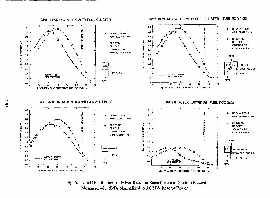
SPD1 IN XC1-G7 WITH EMPTY FUEL CLUSTER SPD1 IN XC1-G7 WITH EMPTY FUEL CLUSTER + FUEL ROD 2123
E
agCD
I2
Q
2.4
2.2
2.0
1.8
1.6
1.4
1.2
1.0
0.8
0.6
0.4
0.2
0.0
-
- 6
/ ' - ' \
ACTIVE LENGTHOF DETECTOR
10 20 30 40 50 60 70
DISTANCE ABOVE BOTTOM OF FUEL COLUMN, cm
• CR BANK AT 542
AXIAL FACTOR =1.50
O CR 3 AT 781
CR 2 OUT
OTHER CR'S IN
AXIAL FACTOR = 1.34
CH2
• XC1-G7
SPD1
E
10 20 30 40 50 60
DISTANCE ABOVE BOTTOM OF FUEL COLUMN, cm
• CH BANK AT 535
AXIAL FACTOR = 1.47
O CH 3 AT 736
CR2OUT
OTHER CR'S IN
AXIAL FACTOR = 1.35
SPD2 IN IRRADIATION CHANNEL-E6 WITH PLUG SPD2 IN FUEL CLUSTER-F8 - FUEL ROD 2123
LUDCDC
2.4
2.2
2.0
I B
1.6
1.4
1.2
1.0
0.8
0.6
0.4
0.2
0.0
-
-
-
-
_
- /v'/1
~m/
.0
i • 1 • 1 > r
a—or' ^̂ K
' \
ACTIVE LENGTHOF DETECTOR
— , 1 1 1 1
|
8tu
£
\ a.g
, \\ \\ \V\ \
IB \
_
-
10 20 30 40 50 60
OISTANCE ABOVE BOTTOM OF FUEL COLUMN, cm
• CR BANK AT 542
AXIAL FACTOR . 1 31
O CR 3 AT 781
CR2OUT
OTHER CR'S IN
AXIAL FACTOR = 1.31
• E7
E6
2.4
2.2
2.0
1.8
1.6
1.4
1.2
1.0
0.8
0.6
0.4
0.2
0.0
Su.Oa.p
• CR BANK AT 535
AXIAL FACTOR = 1.65
O CR 3 AT 736
C R 2 O U T
OTHER CR'S IN
AXIAL FACTOH = 1.28
SPD2
CR2
T
L42
•>
- * - F8
FUEL ROD 2123
XCl G7
DISTANCE ABOVE BOTTOM OF FUEL COLUMN, cm
Fig. 6. Axial Distributions of Silver Reaction Rates (Thermal Neutron Fluxes)Measured with SPDs Normalized to 3.0 MW Reactor Power.
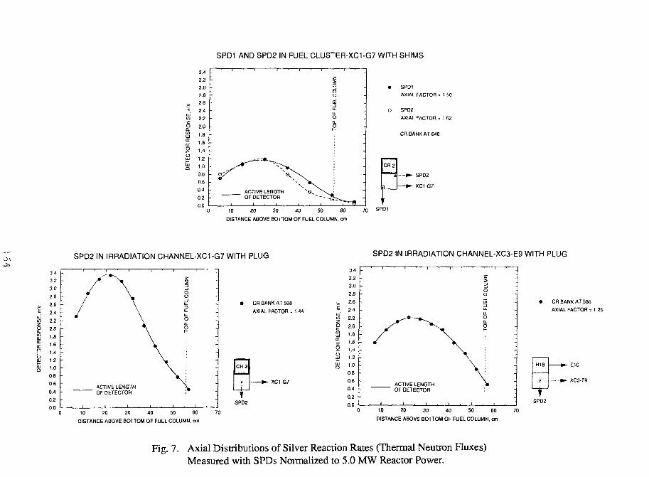
SPD1 AND SPD2 IN FUEL CLUS~ER-XC1-G7 WITH SHIMS
SPD1
AXIAL FACTOR = 1 50
O GPD2
AXIAL FACTOR - 1 (52
CR BANK AT 640
-•>- SPD2
-••- XC1 G7
10 20 30 40 50 60
DISTANCE ABOVE BO ITOM OF FUEL COLUMN, cm
SPD1
SPD2 IN IRRADIATION CHANNEL-XC1-G7 WITH PLUG SPD2 IN IRRADIATION CHANNEL-XC3-E9 WITH PLUG
CR BANK AT 598
AXIAL FACTOR = 1 44
XC1-G7
3.4
3.2
3.0
2.8
2.62.42.22.01.6
1.6
1.4
1.2
1.0 -
0.8
0.6
0.4
0.2
0.0
ACTIVE LENGTHOF DETECTOR
DISTANCE ABOVE BOTTOM OF FUEL COLUMN, cm
10 20 30 40 50 60
DISTANCE ABOVE BOTTOM OF FUEL COLUMN, cm
CR BANK AT 58B
AXIAL FACTOR = 1
E10
XC3-E9
SPD2
Fig. 7. Axial Distributions of Silver Reaction Rates (Thermal Neutron Fluxes)Measured with SPDs Normalized to 5.0 MW Reactor Power.
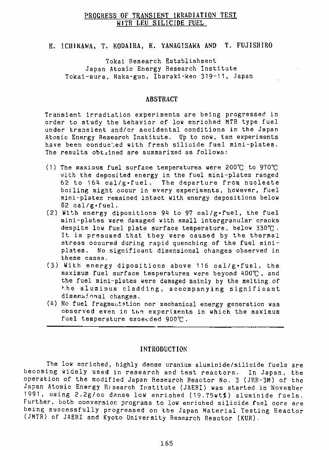
PROGRESS OF TRANSIENT IRRADIATION TESTWITH LEU SILICIDE FUEL
H. ICHIKAWA, T. KODAIRA, K. YANAGISAWA AND T. FUJISHIRO
Tokai Research EstablishmentJapan Atomic Energy Research I n s t i t u t e
Tokai-mura, Naka-gun, Ibaraki-ken 319-11, Japan
ABSTRACT
Transient i r radiat ion experiments are being progressed inorder to study the behavior of low enriched MTR type fuelunder t ransient and/or accidental conditions in the JapanAtomic Energy Research Ins t i tu te . Up to now, ten experimentshave been conducted with fresh s i l ic ide fuel mini-plates.The results obtained are summarized as follows:
(1) The maximum fuel surface temperatures were 200°C to 970°Cwith the deposited energy in the fuel mini-plates ranged62 to 164 ca l /g*fue l . The departure from nucleateboiling might occur in every experiments, however, fuelmini-plates remained intact with energy depositions below82 cal /g-fuel .
(2) With energy dipositions 9U to 97 cal/g«fuel, the fuelmini-plates were damaged with small intergranular cracksdespite low fuel plate surface temperature, below 330°C •I t i s presumed that they were caused by the thermalstress occured during rapid quenching of the fuel mini-plates. No significant dimensional changes observed inthese cases.
(3) With energy d ipos i t ions above 116 ca l /g»fue l , themaximum fuel surface temperatures were beyond 400°C , andthe fuel mini-plates were damaged mainly by the melting of•"he aluminum c l add ing , accompanying s i g n i f i c a n tdimensional changes.
(4) No fuel fragmentation nor mechanical energy generation wasobserved even in the experiments in which the maximumfuel temperature exceeded 900°C •
INTRODUCTION
The low enriched, highly dense uranium aluminide/silicide fuels arebecoming widely used in research and t e s t r e a c t o r s . In Japan, theoperation of the modified Japan Research Reactor No. 3 (JRR-3M) of theJapan Atomic Energy Research I n s t i t u t e (JAERI) was star ted in November1991, using 2 .2g/cc dense low enriched (19.75wt%) aluminide f u e l s .Further, both conversion programs to low enriched s i l i c ide fuel core arebeing successful ly progressed on the Japan Material Testing Reactor(JMTR) of JAERI and Kyoto University Research Reactor (KUR).
165
In order to establish a data base on the behavior of the lowenriched plate-type fuels under transient/accidental conditions, thetransient irradiation experiments on these fuels are being progressed fromDecember 1990, by the pulse irradiation using the Nuclear Safety ResearchReactor (NSRR) of JAERI-Tokai.
The NSRR is a modified TRIGA-ACRP (Annual Core Pulse Reactor) whichwas built for investigating the nuclear fuel behavior under a reactivityinitiated accident (RIA) condition. A positive reactivity of 4.67$ canbe inserted to the core in maximum, generating the pulse reactor power of23,000 MW with a half width of U.U msec. The general objectives of theNSRR pulse irradiation tests are to determine threshold energy for fuelfailure and to investigate its mechanism and failure consequences underRIA conditions for the Light Water Reactor (LWR) fuels. At present, notonly uniii-adiated LWR fuels but pre-irradiated LWR fuels and fresh plate-type aluminide/silicide fuels are available as test fuels.
We reported the results of first stage experiments with silicidefuel mini-plates at the last RERTR meeting held in Jakarta, Indonesia."After that, another six experiments have been conducted, in which thefuel behavior at relatively low temperature, below 400°C F were studiedin detail, trying to simulate the temperature excursion in fuel platesduring a transient or RIA conditions of research and test reactors.2)
TRANSIENT IRRADIATION EXPERIMENT
1 . Fuel Mini-plate
The fuel mini-plates used in the transient irradiation experimentshave same dimension of 35 mm X 130 mm X 1.27 mm, with fuel core of 25mm X 70 mm X 0.51 mm. Three kinds of fuel mini-plate with defferenturanium densities are prepared, however, only 4.8g/cc fuel mini-plateshave been provided to the experiments, up to now. These fuel mini-plateswere fablicated by CERCA, Franse and B&W, USA. The tensile strength ofthe aluminum cladding are aproximately 230 MPa and 120 MPa for CERCA'splates and B&W's, respectively, and the 0.2% yield strength are 120 MPaand 60 MPa, respectively.
2. Instrumentations and Irradiation Capsules
Five Pt/Pt-13?Rh thermocouples (hereinafter abbreviated WC's), ofwhich melting point was 1,780°C, were spot welded directly to one side ofthe surface of each fuel mini-plate at five different locations. Afterassembling to the supporting device, fuel mini-plate was contained in airradiation capsule with stagnant water at the room temperature and atone atomospheric pressure. The capsule is a pressure vessel made by thestainless steel. Two capsule pressure sensors and a water level sensorwere also installed inside the capsule in order to monitor the pressurepulse and water hammer force caused by the melting and/or fragmentationof fuel mini-plate.
3. Pulse Power History
The deposited energy in fuel mini-plate by pulse irradiation ispromotional to the integral value of the reactor pulse power. The
166
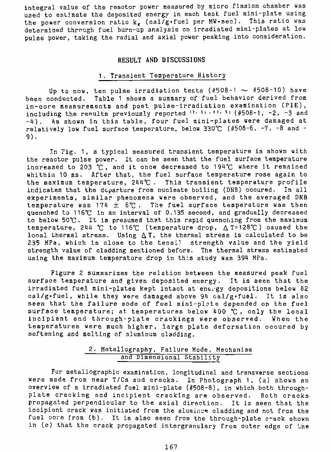
integral value of the reactor power measured by micro fission chamber wasused to estimate the deposited energy in each test fuel mini-plate usingthe power conversion ratio kg (cal/g«fuel per MW«sec). This rat io wasdetermined through fuel burn-up analysis on irradiated mini-plates at lowpulse power, taking the radial and axial power peaking into consideration.
RESULT AND DISCUSSIONS
1 . Transient Temperature History
Up to now, ten pulse irradiation tests (#508-1 ~ #508-10) havebeen conducted. Table 1 shows a summary of fuel behavior derived fromin-core measurements and post pulse- i r radiat ion examination (PIE),including the results previously reported " • 3> • " • 5 ) (#508-1, -2, -3 and- 4 ) . As shown in this table, four fuel mini-plates were damaged atrelatively low fuel surface temperature, below 330°C (#508-6, -7, -8 and -9).
In Tig. 1, a typical measured transient temperature is shown withthe reactor pulse power. It can be seen that the fuel surface temperatureincreased to 203 °C. and i t once decreased to 194°C where i t remainedwhithin 10 us. After that, the fuel surface temperature rose again tothe maximum temperature, 244°C • This transient temperature profileindicates that the departure from nucleate boiling (DNB) occured. In allexperiments, similar phenomena were observed, and the averaged DNBtemperature was 174 ± 6°C . The fuel surface temperature was thenquenched to 116°C in an interval of 0.135 second, and gradually decreasedto below 50°C • I t is presumed that this rapid quenching from the maximumtemperature, 244 °C to 116°C (temperature drop, AT = 128°C) caused thelocal thermal s tress . Using AT, the thermal stress is calculated to be235 MPa, which is close to the tensi.1 strength value and the yieldstrength value of cladding mentioned before. The thermal stress estimatedusing the maximum temperature drop in this study was 394 MPa.
Figure 2 summarizes the relation between the measured peak fuelsurface temperature and given deposited energy. I t is seen that theirradiated fuel mini-plates kept intact at energy depositions below 82cal /g ' fuel , while they were damaged above 94 oal/g»fuel. I t i s alsoseen that the fa i lure mode of fuel mini-pl?te depended on the fuelsurface temperature; at temperatures below 400 °C , only the locali nc ip i en t and through-plate crackings were observed. When thetemperatures were much higher, large plate deformation occured bysoftening and melting of aluminum cladding.
2. Metallography, Failure Mode, Mechanismand Dimensional Stability
For metallographic examination, longitudinal and transverse sectionswere made from near T/Cs and cracks. In Photograph 1, (a) shows anoverview of a irradiated fuel mini-plate (#508-8), in which both through-pla te cracking and incipient cracking are observed. Both crackspropagated perpendicular to the axial direction. I t is seen that theincipient crack was initiated from the aluminum cladding and not from thefuel core from (b). It is also seen from the through-plate c^ack shownin (c) that the crack propagated intergranulary from outer edge of Ihe
167
cladding.
Figure 3 shows the failure maps of the fuel mini-plates damaged inpulse irradiation tests from #508-3 to #508-9, in which the depositedenergy were 94 to 164 cal/g'fuel. In this figure, relative locationsand numbers of cracks, seperations from the fuel core and distribution ofthe molten aluminum holes are presented.
Dimensional stability of mini-plates under pulse irradiation wasalso studied using data from PIE and the summary is shown in Table 1 .The maximum bowing of each sections cut from mini-plates are all withinthe range of previously reported. It should be noted that the failuresobserved below 400°C in this study were not accompanied by significantchanges in the plate dimension, that is, the thermal stress was extremelylocalized.
CONCLUSIONS
Transient irradiation experiments are being progressed on the lowenriched silicide fuel mini-plates by the pulse irradiation. Tenexperiments have been conducted with fresh silicide fuel mini-platescooled by stagnant water at room temperature and at atomosphericpressure. The results obtained are summarized as follows:
(1) The maximum fuel surface temperatures were 200°C to 970°C with tnedeposited energy in the fuel mini-plates ranged 62 to 164 cal/g'fuel.The departure from nucleate boiling might occur in every experiments,however, fuel mini-plates remained intact with energy depositions below82 cal/g«fuel. Fuel mini-plates were damaged with energy depositionsabove 94 cal/g'fuel.
(2) With energy dipositions 94 to 97 cal/g'fuel, fuel plates weredamaged with small intergranular cracks despite low fuel plate surfacetemperature, below 330 °C • These failures might be attributed to thelocal thermal stress caused by the rapid quenching of fuel mini-plates.The intergranular cracks have propagated from the plate surface to thefuel core. No significant dimensional change- 'iserved in these cases.
(3) With energy dipositions above 116 cal/g'fuel, the maximum fuelsurface temperatures were beyond 400°C , and fuel plates were damagedmainly by ths melting of the aluminum cladding, accompanying significantdimensional changes.
(4) No fuel fragmentation nor mechanical energy generation was observedeven in the experiments in which the maximum fuel temperature exceeded 900
The transient irradiation experiments on the low enriched uraniumMTR-type fuel are planned to be continuously progressed for several years;the experiments in which more severe conditions will be provided, theexperiments using aluminide fuels and pre-irradiated fuel mini-plates,and so on.
168
ACKNOWLEDGMENT
The a u t h o r s wish to thank Mr. E. Sh ' i r a i , D i r e c t o r , Department ofResearch Reactor and Mr. I . Kobayashi ; Director , Department of Fuel SafetyR e s e a r c h and Dr . Y. F u t a m u r a , D i r e c t o r , JMTR P r o j e c t f o r t h e i rencouragement and promotion of t h i s work.
REFERENCES
1)H. ICHIKAWA e t a l . , "Behavior of Low Enriched Uranium S i l i c i d e Mini-P la tes Under Transient I r r a d i a t i o n " , Proceedings of 14th I n t e r n a t i o n a lRERTR meeting, to be publ i shed .
2)K.YANAGISAWA e t a l . , "Study on T r a n s i e n t Behavior of Low EnrichedUranium S i l i c i d e P l a t e Type Fuel for Research Reac to rs d u r i n g RIACondit ions" , Journal of Nucl. S c i . & Technol . , to be publ ished.
3)K. YANAGISAWA e t a l . , "Technical r e p o r t : Technical Development on theS i l i c i d e P la t e - type Fuel Experiment at Nuclear Safety Research Reactor",JAERI-M 91-11U (1991)
U)K. YANAGISAWA, "Post -pulse D e t a i l Metal lographic Examinations of Low-enriched Uranium S i l i s i d e Pla te-Type Minia ture Fuel" , JAERI-M 91-152(1991)
5)K. YANAGISAWA e t a l . , "Dimensional S t a b i l i t y of Low Enriched UraniumS i l i c i d e Plate-Type Fuel for Research Reactors a t Transient Condit ions", Journal of Nucl. Sc i . & Technol . , 29[3] , 233 (1992)
6)K. YANAGISAWA e t a l . , "Study of T rans i en t Behavior of Low EnrichedS i l i c i d e Fuel P l a t e s by PuJse I r r a d i a t i o n in the NSRR", Proceedings ofthe 3rd Asian Symposium on Research Reactor, JAERI-M 92-028 (1992)
169
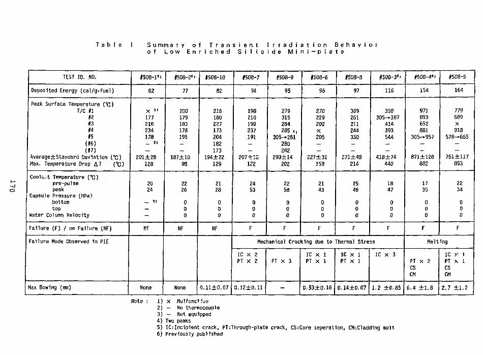
T a b l e 1 S u m m a r y o f T r a n s i e n t I r r a d i a t i o n B e h a v i o ro f L o w E n r i c h e d S i l i c i d e M i n i - p l a t e
TEST ID. NO.
Deposited Energy (cal/g-fuel)
Peak Surface Temperature (°C)T/C #1
n#3#4US(«)(#7)
Average±Standard Deviation {°C)Max. Temperature Drop AT [°C)
Cooliiut Temperature CC)pre-pulsepeak
Capsule Pressure (MPa)bottomtop
Water Column Velocity
Failure (F) / no Failure (NF)
Failure Mode Observed in PIE
Max Bowing (mm)
#508-1''
62
X »»177216234178_ 4>
—
201±28128
2024
_ 3)
—
—
NF
None
#508-2s>
77
200179183178195__
187±1098
2226
000
NF
None
#508-10
82
216180227173204182173
194±22129
2128
000
NF
0.11±0.07
#508-7
94
198210199237191_—
207+ IS122
2453
000
F
#508-9
95
279315284285 4,
305-261280282
290±14202
2258
000
F
#508-6
96
270229202X205_—
227±31159
2143
000
F
Mechanical Cracking due to
IC x ZPT X 2
0.12+0.11
PT X 3
-
IC X 1PT X 1
0.53±0.16
1508-8
97
309261211244330_—
271±48214
2546
000
F
05O8-36'
116
350305-387
414393544——
418±74440
1847
000
F
Thermal Stress
IC X 1PT X 1
0.14±0.07
IC X 3
1.2 ±0.85
#508-46>
154
9718936528B1
305—957——
871 ±128
882
1735
000
F
#508-5
164
779689X918
578—665——
761±117
853
2234
000
F
Melting
PT X 2CSCM
6.4 ±1.8
ic y iPT X 1CSCM
2.7 ±1.2
Note : 1) X Mulfunction2) — No thermocouple3) — Not equipped4) Two peaks5) IC:Incipient crack, PT:Through-plate crack, CS:Core seperation, CM:Cladd1ng melt.6) Previously published
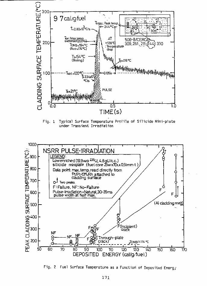
uoUJ
iHiCL
300
9 7cal/g-fue!Trriax:R?akteiTip-
244 "Cwr*
3.09,261,
Si
0.5
TIME(s)1.0
Fig. 1 Typical Surface Temperature Profile of Silicide Mini-plateunder Transient Irradiation
UJcr1
•1000s.
i'900
300DC
^700
u?0 0
o^500
in
o
§300
^200UJQ_
N5RR PULSE-IRRADIATIONLEGEND:
Low enriched (19.9w/o ̂ U , 48gU/c.c.)silicide miniplate. (fuel core 25wx70Lx0.5lmnrt )1
Data point: max. temp, read directly fromPt/PM3%Rh attached to
i cladding surfaceCH Two peaks
F: Failure, NF: No-FailurePulse-irradiation =NaturalJ30-35mspulse width at half max.
( - r h r o u g h_p l a t e
«*L ^m °c
60 70 80 90 100 110 120 130 140 150 160 170DEPOSITED ENERGY (cal/g-fueI)
Fig. 2 Fuel Surface Temperature as a Function of Deposited Energy
171
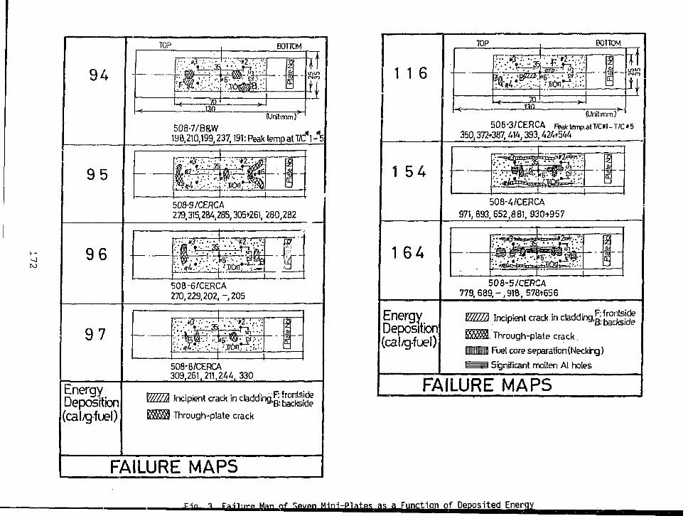
94
BOTTOM
(Urtt:mm)508-7/B&W m
198,210,199,237,191: Peak temp at T/C 1 -"5
95
508-9/CERCA279,315,284,285,305*261, 280,282
96 »5'. ••. • '&lBa•'.T/CifiT~Tl—r"I"
508-6/CERCA270,229,202,-205
97 * \ ' m ' ' *1 • T-i •1 • • « ' .UT ••
1
!EL
508-8/CERCA309.261,211,24/;, 330
nergyDeposition(cal/gfuel)
Incipient e ra * ii
Through-plate crack
B: backside
FAILURE MAPS
Man <-»f
1 1 6
TOP BOTTOM
,»3:- • • • ' • t " * 2 . ' . - . " :
JZQ.
(Unil:mm)506-3/CERCA Fteklenp.alT/Cn-T/C*5
350,372*387,414,393,424+544
1 5A
508-4/CERCA971,893, 652,881, 930->957
1 64
50 8-5/CERCA779,689,-,918, 578*656
EnergyDeposition(cal/gfuel)
MEL Incipient crack in cladding,^
122^3. Through-plate crack
Uiimiiil Fuel core separation (Necking)
I I Significant molten Al holes
FAILURE MAPS
as ^Function of DeDosited Enerqy
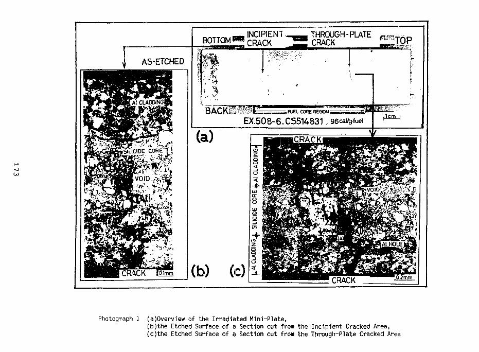
A5-ETCHED
BOTTOM
(a)
INCIPIENTCRACK
THROUGH-PLATECRACK
FUEL CORE REGION
EX.508-6.C5514831 , 96cal*jfuel
(b) (c)CRACK
Photograph 1 (a)Overview of the Irradiated Mini-Plate,(b)the Etched Surface of a Section cut from the Incipient Cracked Area,(c)the Etched Surface of a Section cut from the Through-Plate Cracked Area
A SWELLING MODEL OP LEU SILICIDE FUEL FOR KMRR
Woan Hwang*, B.G. Kim, K.S. Sim, Y.H. Heo, Ho Chun SUKKorea Atomic Energy Research Ins t i t u t e
P.O. Box 7, Daeduk-Danji, Daeieon, Korea
ABSTRACT
A lot of efforts have been made internationally to understand theirradiation behavior and the safety characteristics of uraniumsilicide fuel. One of the important irradiation performance charac-teristics of the silicide dispersion fuel element is the diametralincrease resulting from fuel swelling. This paper represents an at-tempt to develop the physical model for the swelling, DFSWELL, bymodelling the basic irradiation behavior observed from in-reactorexperiments. The most important part of developing the swellingmodel is the identification of the controlling physical processes.The swelling of the silicide fuel is comprised of the volume changedue to three major components ; i) the formation of an interfacia!layer between the fuel particle and matrix, ii) the accumulation ofgas bubble nucleation, iii) the accumulation of solid fission pro-ducts. In this study, the swelling of the fuel element is quantita-tively estimated by considering temperature, fission rate, solidfission product build-up and gas bubble behavior. The DFSWELL modelwhich takes into account the above physical components predicts wellthe absolute magnitude of silicide fuel swelling in accordance withthe power histories in comparison with the experimental data.
INTRODUCTION
In Korea, the Korea Mulipurpose Research Reactor (KMRR) is under con-struction at KAERl(Korea Atomic Energy Research Institute). The KMRR driverfuel will be made from elements of an extruded uranium silicide dispersionin aluminum, with finned aluminum cladding and aluminum end plugs. The fuelcore consists of a dispersion of small particles of a high density uraniumsilicide compound in a continuous aluminum matrix. The reference fuelmaterial for the KMRR fuel has a nominal composition of 61 w t % U3Si and39 w t % Al. We began to develop the fuel performance code to predict theirradiation behavior of U3Si-Al dispersion fuel elements in researchreactors as well as the technique for fabricating the fuel elements.
In reactor irradiation experiments with intermetallic uranium com-pounds, Hofman showed [1] that an enormous increase in gas bubble gro-'thoccurs when a compound becomes amorphous during irradiation. As a resultof the interaction of different processes, a material density change so--called fuel swelling, and material phase change, as well as nuclear pro-perty changes due to uranium burnup occur.
174
To develop a comprehensive swelling model, some controlling physicalprocesses on the irradiation behavior of silicide fuel are identified byanalyzing the irradiation behaviors reported from the 1iteratures[l-12] inthis study. This paper represents an attempt to develop a physical modelto efficiently predict the swelling of the silicide fuel according topower history.
PHYSICAL PROCESSES FOR DISPERSION FUEL CORE SWELLING
The most important part of developing a physical model is the identi-fication of the controlling physical processes. So far, some contributingmechanisms [1,4,5,6,11] have been suggested for the swelling of silicidedispersion fuel. However the mechanisms of the swelling behavior for sili-cide fuel do not fully explain the observed swelling phenomena. Accordingly,it is necessary to extensively identify the controlling processes to developa comprehensive swelling model. Hence, the limited amount of experimentalevidences acquired so far have led to the following conclusive-controllingphysical processes :(i) U3Si—Al and U3Si2-Al are thermodynamical ly unstable. The type and
amount of reaction products (uranium aluminides) formed, obviously varieswith concentration and temperature, and can be predicted from the ternaryphase diagram. The uranium aluminides UA12, UA1 3 and UA1 4 + 3 C dissolvesubstantial amounts of silicon at higher temperatures, the solubility ishowever, in the case of UA1 2 and UAl 3, temperature dependc1: [2],(ii) From the result of FZZ-909A experiment, post-irradiation metallogra-
phy revealed that interfacial layers around reacted silicide particles hadreached a thickness of 7.5 /Am near the fuel core periphery and 25 /Amaround particles near the fuel core centre. Again " reacted silicide "particles had coalesced [3].(iii) The swelling observed in most specimens was clearly associated with
a reaction between the fuel particles and the aluminum matrix, the aluminumhaving reacted with particle surfaces and also penetrated along networks ofgrain boundaries to attack sub-grains throughout the U 3Si. The end point ofsuch a reaction would occur when all the U3Si(and the precipitates of U 3 S i 2
contained within the U3Si particles) had been consumed to form U A l 3 S i 1 / 3 .Rates of reaction would be reduced eventually (as observed) due to the im-pedence, offered to diffusing aluminum atoms, by the U A l 3 S i 1 / 3 surroundingthe U3Si particles and growing in thickness [4,5].(iv) The volume change due to uranium burnup will be calculated using the
most current uranium-silicon equilibrium phase diagram and measured densi-ties of the phases involved. The amounts of non-gaseous fission productswere determined with the aid of published fission yield data for U-235.These contributions to volume change were estimated by evaluating theirsolubility in the fuel and the tendency to form compounds with each otherand with uranium and silicon. These two contributions to swelling, i.e.,phase transformation and non-gaseous fission products were combined andyielded as a linear function of fission density. The largest component ofthe fuel swelling is due to the formation of fission gas bubbles [6],(v) Nucleation of fission gas bubble in U3Si fuel was apparently very
uniform as compared to the USi*Al fuel. But the fission gas bubble sizeswere larger near the fuel core periphery than at the fuel core centre in
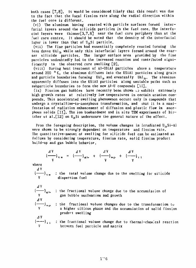
both cases [7,8]. It would be considered likely that this result was dueto the fact that the local fission rate along the radial direction withinthe fuel core is different.(vi) The aluminum having reacted with particle surfaces formed inter-facial layers around the silicide particles in the fuel core. The interfa-cial layers were thinner[3,7,8] near the fuel core periphery than at the•"iiel core centre. It should be noted that the density of the interfaciallayer is lower than that of U3Si particle,(vii) The fine particles had essentially completely reacted forming theless dense UA1 3 while only thin interfacial layers formed around the coar-ser silicide particles. The larger surface area provided by the fineparticles undoubtedly led to the increased reaction and contributed signi-ficantly to the observed core swelling [9].(viii) During heat treatment of Al-USiAl particles above a temperature
around 200 ° C, the aluminum diffuses into the USiAl particles along grainand particle boundaries forming UAI 3 and eventually UAl 3. The aluminumapparently diffuses into the USiAl particles along unstable paths such assubparticle boundaries to form the new Al-U compounds [10].(ix) Fission gas bubbles have recently been shown 10 exhibit extremely
high growth rates at relatively low temperatures in certain uranium com-pounds. This accelerated swelling phenomenon occurs only in compounds thatundergo a crystalline-to-amorphous transformation, and that it is a mani-festation of radiation enhancement of diffusion and plastic flow in amor-phous solids [11]. The ion bombardment and in situ TEM experiments of Bir-tcher fct al.[12] on U3Si underscore the general nature of the effect.
From the foregoing description, the volume changes in irradiated U3Si-Alwere shown to be strongly dependent on temperature and fission rate.The quantitative-amount ot swelling for silicide fuel can be estimated asfollows by considering temperature, fission rate, solid fission productbuild-up and gas bubble behavior.
JV JV 4V JVf K s = { )Bb + { Jap + ( h i
V V V Vwhere
A\{ } t B : the total volame change due to the swelling for silicide
V dispersion fuel
{ } B b : the fractional volume change due to the accumulation ofV gas bubble nucleation and growthAV
{ } s p : the fractional volume changes due to the transformation tuV a higher silicon phase and the accumulation of solid fission
prodvt swelling
}ii : the fractional volume change due to thermal-chemical reactionbetween fuel particle and matrix
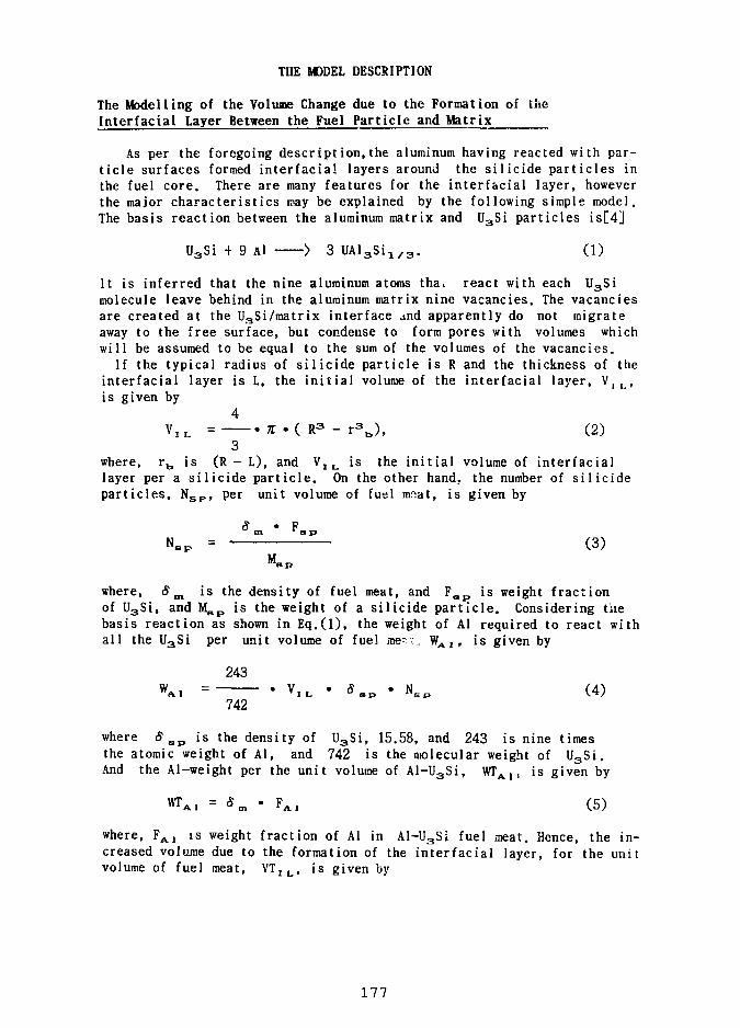
THE M3DEL DESCRIPTION
The Modelling of the Volume Change due to the Formation of theInterfacial Layer Between the Fuel Particle and Matrix
As per the foregoing description,the aluminum having reacted with par-ticle surfaces formed interfacial layers around the silicide particles inthe fuel core. There are many features for the interfacial layer, howeverthe major characteristics may be explained by the following simple model.The basis reaction between the aluminum matrix and U3Si particles is[4]
U3Si + 9 Al > 3 U A l 3 S i 1 / 3 . (1)
It is inferred that the nine aluminum atoms thai react with each U3Simolecule leave behind in the aluminum matrix nine vacancies. The vacanciesare created at the U3Si/matrix interface and apparently do not migrateaway to the free surface, but condense to form pores with volumes whichwill be assumed to be equal to the sum of the volumes of the vacancies.
If the typical radius of silicide particle is R and the thickness of theinterfacial layer is L, the initial volume of the interfacial layer, V,, ,is given by
4V I L = • 7T . ( R 3 - r 3 j , (2)
3where, r b is (R - L), and V 1 L is the initial volume of interfaciallayer per a silicide particle. On the other hand, the number of silicideparticles, N S P , per unit volume of fuel mnat, is given by
(3)
where, 8m is the density of fuel meat, and F s p is weight fractionof U 3Si, and M s p is the weight of a silicide particle. Considering thebasis reaction as shown in Eq.(l), the weight of Al required to react withall the U 3Si per unit volume of fuel me".;, W A 1 , is given by
243WA. = • V I L • Sap • N E p (4)
742
where S s p is the density of U 3Si, 15.58, and 243 is nine timesthe atomic weight of Al, and 742 is the molecular weight of U 3Si.And the Al-weight per the unit volume of Al-U3Si, W T A l t is given by
wrA1 = sm . F A 1 (5)
where, F A 1 is weight fraction of Al in Al-U3Si fuel meat. Hence, the in-creased volume due to the formation of the interfacial layer, for the unitvolume of fuel meat, V T I L , is given by
177
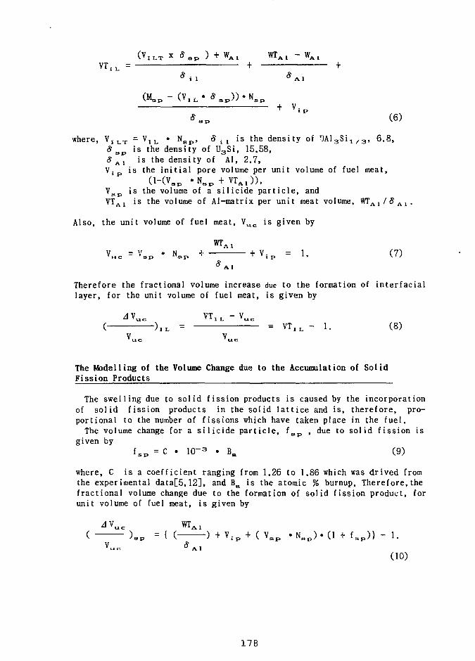
( v I L T x s s p ) + w A 1 w r A 1 - w A 1V T I L =
S i 1 S A 1
( M . P - (V. i . - g B p ) ) * N s p
* a p + V ' P (6)
where, V I L T = V I L • N a p , 8^ is the density of " JAlgSi i / 3 , 6 .8 ,S s p is the density of U3Si, 15.58,$ A1 is the density of Al, 2.7,V i p is the in i t i a l pore volume per unit volume of fuel meat,
O -(\ • N + VT "HV'ap " s p T ' ' A l ^ 'V s p i s the volume of a s i l i c i d e p a r t i c l e , andVT A l i s the volume of Al-matr ix per u n i t meat volume, W T A I / 5 ' A 1 .
Also, the u n i t volume of fuel meat, V u c i s g iven by
u c = v s p . N S P ^ + v i p = l. (7)
Therefore the fractional volume increase due to the formation of inter faciallayer, for the unit volume of fuel meat, is given by
^ V _ V T 1 L - V U C
( ) I L = = V T I L - 1. (8)V V
The Modelling of the Volume Change due to the Accumulation of SolidFission Products
The swelling due to solid fission products is caused by the incorporationof solid fission products in the solid lattice and is, therefore, pro-portional to the number of fissions which have taken place in the fuel.The volume change for a silicide particle, f s p , due to solid fission is
given byf s p = C • 1 0 -
3 • B a (9)
where, C is a coefficient ranging from 1.26 to 1.86 which was drived fromthe experimental data[5,12], and B a is the atomic % burnup. Therefore,thefractional volume change due to the formation of solid fission product, forunit volume of fuel meat, is given by
w r A 1 v i p + ( v s p . Nap) • (l + f s p ) } - l .
(10)
178
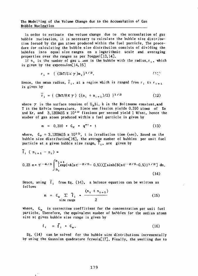
The ModelHng of the Volume Change due to the Accumulation of GasBubble Nucleation
In order to estimate the volume change due to the accumulation of gasbubble r.ucleation, it is necessary to calculate the bubble size distribu-tion formed by the gas atoms produced within the fuel particle. The proce-dure for calculating the bubble size distribution consists of dividing thebubbles into equal size ranges on a logarithmic scale and averagingproperties over the ranges as per Poeppel[13,14].
If ni is the number of gas 0,0ms in the bubble with the radius, r i t whichis given by the expression[14,15]
r, = { (3kT/8Jfr)n,}1 / 2
Hence, the mean radius, r p at a region which is ranged from r; to ri + 1
is given by
7, = { (3kT/87Tr) ((ns + n i + 1)/2) }1 / 2 (12)
where 7 is the surface tension of U3Si, k is the Boltzmann constant,andT is the Kelvin temperature. Since one fission yields 0.310 atoms of Xeand Kr, and 3.1209415 x 1 0 1 0 fissions per second yield 1 W/sec, hence thenumber of gas atoms produced within a fuel particle is given by
m = 0.310 • C F • q1" • t (13)
where, C F = 3.1209415 x 1 01 0 , t is irradiation time (sec). Based on the
bubble size distribution[16], the average number of bubbles per unit fuelparticle at a given bubble size range, f;, are given by
fn£ _0.23 m« r - 4 / 5 [exp(-A(nr-2/s- 0.5))][sinh{B(nr-2/5-0.5)}x/2] dn.
J n.(14)
Hence, using f. from Eq. (14), a balance equation can be written asfollows
(n, + n 1 + 1 )m = Cs Z f, • (15)
size range 2
where, C s is correction coefficient for the concentration per unit fuelparticle. Therefore, the equivalent number of bubbles for the median atomssize at given bubble size range is given by
U = fi ' C s. (16)
Eq. (14) can be solved for the bubble size distributions incrementallyby using the Gaussian quadrature fcrmula[17]. Finally, the swelling due to
179
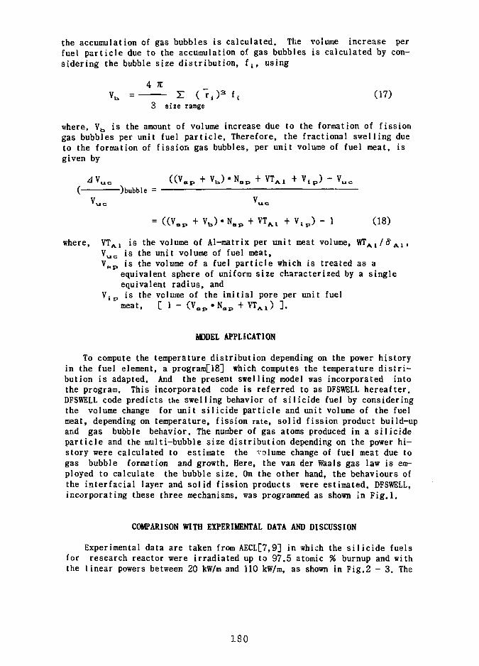
the accumulation of gas bubbles is calculated. The volume increase perfuel particle due to the accumulation of gas bubbles is calculated by con-sidering the bubble size distribution, fs, using
4 itVb = r ( r 4 )
3 f, (17)3 size range
where, V b is the amount of volume increase due to the formation of fissiongas bubbles per unit fuel particle. Therefore, the fractional swelling dueto the formation of fission gas bubbles, per unit volume of fuel meat, isgiven by
AM ((V + V ^ • N + V T + V ^ - Va *uc U'ap ' 'b/ "sp ' MAl ' " i p' *uc
( ) bubble =
= « V . P + V b ) . N a p + V T A l + V i p ) - 1 (18)
where, V T A 1 is the volume of Al-matrix per unit meat volume, WT A 1/<5 A
V u c is the unit volume of fuel meat,V s p is the volume of a fuel particle which is treated as a
equivalent sphere of uniform size characterized by a singleequivalent radius, and
V- o is the volume of the initial pore per unit fuel" meat, [ 1 - (V s p • N a p + V T A 1 ) ].
MODEL APPLICATION
To compute the temperature distribution depending on the power historyin the fuel element, a program[18] which computes the temperature distri-bution is adapted. And the present swelling model was incorporated intothe program. This incorporated code is referred to as DFSWELL hereafter.DFSWELL code predicts the swelling behavior of silicide fuel by consideringthe volume change for unit silicide particle and unit volume of the fuelmeat, depending on temperature, fission rate, solid fission product build-upand gas bubble behavior. The number of gas atoms produced in a silicideparticle and the multi-bubble size distribution depending on the power hi-story were calculated to estimate the volume change of fuel meat due togas bubble formation and growth. Here, the van der Waals gas law is em-ployed to calculate the bubble size. On the other hand, the behaviours ofthe interfacial layer and solid fission products were estimated. DFSWELL,incorporating these three mechanisms, was programmed as shown in Fig.l.
COMPARISON WITH EXPERIMENTAL DATA AND DISCUSSION
Experimental data are taken from AECL[7,9] in which the silicide fuelsfor research reactor were irradiated up to 97.5 atomic % burnup and withthe linear powers between 20 kW/m and 110 kW/m, as shown in Fig.2 - 3. The
180
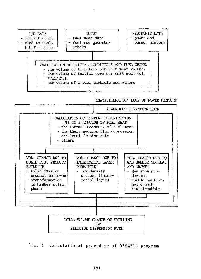
T/H DATA- coolant cond.- clad to cool.F.H.T. coeff.
CALCULATION
INPJT- fuel meat data- fuel rod geometry- others
NEUTRONIC DATA- power andburnup history
3F INITIAL CONDITIONS AND FUEL GEOME.- the volume of Al-matrix per unit meat volume,- the volume of initial pore per unit meat vol.- WTal/tfaX- the volume of a fuel particle and others
idata,ITERATION LOOP OF POWER HISTORY
i ANNULUS ITERATION LOOP
CALCULATION OF TEMPER. DISTRIBUTIONTi IN i ANNULUS OF FUEL MEAT
- the- theanc
thermal conduct, of fuel meatther. neutron flux depressionlocal fission rate
- others
1VOL. CHANGE DUE TOSOLID FIS. PRODUCTBUILD UP- solid fissionproduct build-up
- transformationto higher silic.phase
I
VOL. CHANGE DUE TOINTERFACIAL LAYERFORMATION- low densityproduct (inter-facial layer)
VOL. CHANGE DUE TOGAS BUBBLE NUCLEA.AND GROWTH- gas atom pro-duction
- bubble nucleat.and growth(multi-bubble)
TOTAL VOLUME CHANGE OF SWELLINGFOR
SILICIDE DISPERSION FUEL
Fig. 1 Calculational procedure of DFSWELL program
181
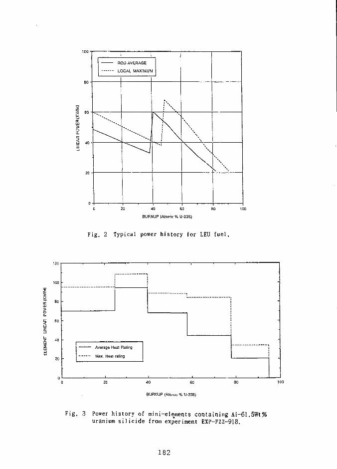
80 -
tr
oa.tr5 40 -
20
0
20 AVERAGE
LOCAL MAXIMUM
\
S. [ \
j \ [ \
\
20 40 60
BURNUP (Atomic % U-235)
Fig. 2 Typical power history for LEU fuel.
120
80
20
Average Heat Rating
Max. Heat rating
20 40 60
BURNUP (Atomic % U-235)
SO 100
Fig. 3 Power history of mini-elements containing Al-61.5Wt%uranium si 1icide from experiment EXP-FZZ-918.
182
irradiation test elements were fabricated into aluminum-clad full-lengthelement about 292 mm long, the fuel core diameter being 5,49 mm and cladwall thickness 0.76 mm. Each element had six cooling fins at 60°C inter-vals around the cladding, the fin width being 0.76 mm and fin height 1.27mm. The outside diameter of the cladding was 7.01 mm (exceeding fins).Fig.4 shows the results of parametric study on the swelling mechanisms forthe silicide dispersion fuel. From the result,the volume change due to theaccumulation of the solid fission products is proportional to the burnupand its absolute magnitude is relatively less than that of gas bubbles.And, it is apparent that the most dominant parameter of silicide fuelswelling is the volume change due to gas bubble formation and growth.Fig. 5 shows the calculated fuel swelling versus experimental data. Inthis Figure, the DFSWELL code predicted well the absolute magnitude of theswelling, in comparison with the wide variety of experimental data.
CONCLUSIONS AND RECOMMENDATIONS
In this study, a comprehensive swelling model for the silicide disper-sion fuel has been developed by analyzing the basic irradiation behaviorsand some experimental evidences. From the predictions of DFSWELL model andthe experimental evidences, it is proposed that the swelling for silicidefuel is comprised of the following three major components ;
JV dV AV dV
DFSWELL model which takes into account the above three major componentson the physical phenomena, predicts well the absolute magnitude of silicidefuel swelling depending on the power histories in comparison with theexperimental data. It appears that the most dominant parameter of silicidefuel swelling is the volume change due to gas bubble formation and growth.However, it seems that DFSWELL model tends to overpredict in comparisonwith experimental results, especially at the region of low burnup. It istherefore recommended that further work for modelling the formation ofinterfacial layer dependent on the burnup might be required.
REFERENCES
Gerard L. Hofman,"Crystal Structure Stability and Fission Gas Swellingin Intermetallic Uranium Compounds", Journal of Nuclear Materials,Vol. 140, pp.256-263, (1986).S. Nazare'," Investigations of Uranium Silicide-based DispersionFuels for the Use of Low Enrichment Uranium in Research and TestReactors", kfk 3372 B, Jun. (1982).J.C. Wood, M.T. Foo, L.C. Berthiaume, L.N. Herbert, J.D. Schaefer andD. Hawley, " Reduced Enrichment Fuels for CANADIAN Research ReactorsFabrication and Performance", Proceeding of the International Meetingon RERTR, ANL, USA,AECL-CRNL, Oct. (1984).
183
4. J.C. Wood, M.T. Foo, and L.C. Berthiaume," The Development and Testingof Reduced Enrichment Fuels for CANADIAN Research Reactors", Presentedat the International Meeting on Research and Test Reactor Core Conver-sions, ANL, Argonne, Illinois, November(1982)
5. I.]. Hastings and R.L. Stoute,"Temperature-Dependent Swelling in Irra-diated U3Si Fuel Elements", J. Nucl, Mat. Vol.37, p.295-302, (1970).
6. Gerard L. Hofman and Woo-Seog Ryu, "Detailed Analysis of Uranium Sili-side Dispersion Fuel Swelling", The Meeting on Reduced Enrichment forResearch and Test Reactor, Berlin, Sept. (1989).
7. W. Hwang, D.F. Sears, L.C. Berthiaume and A.K. MacCdrmark, "LEU FuelCore Swelling Measurements of Fuel Elements in NRU Bays", MEMORANDUMFMB-86-411, CRNL, (1986).
8. L.C. Berthiaum and J.C. Wood, " Hot Cell Examination of Sections ofFull-size NRU Rod FL-002 Containing LEU Silicide Dispsion Fuel (EXP-FZZ-913) Cell Job 125", EXP-FZZ-91305, CRNL, (1985).
9. D.F, Sears, L.C. Berthiaume and L.N. Herbert, " Fabrication andIrradiation Testing of LEU Fuels at CRNL Status as of 1987 September",AECL-9632, Sep. (1987).
10. Melville A. Feraday, Moon T. Foo, Ross D. Davidson and John E. Winegar," The Thermal Stability of Al-USiAl Dispersion Fuels and Al-U Alloys",Nuclear Technology, Vol. 58, Aug (1982).
11. J. Rest, G.L. Hofman, and R.C. Birtcher, " The Effect of Crystal Stru-cture Stability on the Mobility of Gas Bubbles in Intertnetal1ic UraniumCompounds ", 14th International Symposium on Effects of Radiation onMaterials, ANL, June, (1988).
12. H.C. Suk, W. Hwang, and K.S.Sim, " KAFEPA : A Computer Code for CANDU-PHWR Fuel Performance Analysis under Reactor Normal Operating Condi-tion", Journal of the Korean Nuclear Society, Vol.19, No.3, (Sep. 1987).
13. J. Brian, 0. Knacke, and 0. Kubaschewski, " Thermochemical Propertiesof Inorganic Substances", Springerverlag Publisher, New York (1977).
14. R.B. Poeppel, " An Advanced Gas Release and Swelling Subroutine", ANL,Proceedings of the Conference on Fast Reactor Fuel Element Technology,Session III : Fuel Mechanisms and Properties, New Orleans, Louisiana,April 13-15, (1971).
15. J.W. Harrison, " An Extrapolated Equation of State for Xenon for Usein Fuel Swelling Calculations", Journal of Nuclear Materials, Vol.31,99-106, (1969).
16. W. Hwang, H.C. Suk, Won Mok Jae, " A Comprehensive Fission Gas ReleaseModel Considering Multiple Bubble Sizes on the Grain Boundary UnderSteady-State Conditions," Nuclear Technology Vol. 95, Sep.(1991).
17. Shan S. Kuo, " Computer Applications of Numerical Methods", Addison-We-sley Publishing Company, Massachusetts, Chapter 12 Numerical Integration,p 299-309 (1972).
18. W. Hwang, " A Model for Predicting the Radial Power Profile in CANDUFuel Pellet", M;S. Thesis, Hanyang University (1987).
184
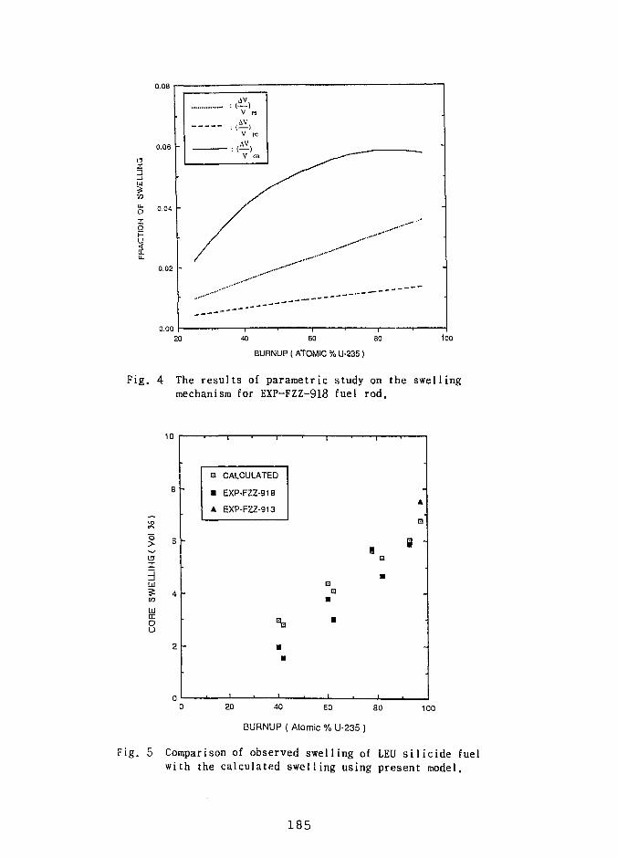
\3
5LU
Xo
0.08
0.06
0.04 -
0.02 -
V ps
V rc
V an
- __ _ „
40 60 80
BURNUP ( ATOMIC % U-235 )
too
Fig. 4 The results of parametric study on the swellingmechanism for EXP-FZZ-918 fuel rod.
10
o
3LU
UlcrOU
8 -
6 -
4 -
2 -
•
-
•
CALCULATED
EXP-FZZ-918
EXP-FZZ-913
•a
13
•
i
•
•
A
u
-
20 40 60 80
BURNUP ( Atomic % U-235 )
100
Fig. 5 Comparison of observed swelling of LEU s i l i c i d e fuelwith the calculated swelling using present model.
1 8 5
A NEW SWELLING MODEL AND ITS APPLICATIONTO URANIUM SILICIDE RESEARCH REACTOR FUEL
by
Gerard L. Hofman, Jeffrey Rest, andJames L. Snelgrove
Argonne National LaboratoryArgonne, Illinois, USA
ABSTRACT
A new version of the dispersion fuel behavior model currently beingincorporated in DART, has been generated. The model's description of fuelswelling - more specifically, the evaluation of fission-gas bubble morphology - issignificantly improved. Although some of the assumptions underlying the basicmodel are derived from systems other than U3Si2, it represents a physicallyrealistic interpretation of the observed irradiation behavior of U3Si2 over a widerange of fission densities and fission rates.
INTRODUCTION
In order to enhance our understanding of the irradiation behavior of uranium silicide, andthereby improve our confidence in predictions that fall outside areas where actual irradiationtesting is feasible, the authors have previously developed a fuel behavior model and implementedit in the DART code.1
New data obtained by reanalyzing previous irradiation experiments performed in the OakRidge Research Reactor (ORR), and preliminary results from a recent high-flux irradiationexperiment in High Flux Isotope Reactor (HFIR), allow us to improve the model. Previousstudies had shown that the development of fission-gas bubbles and the swelling behavior of U3Si2
depended upon the fission rate. The appearance of fission-gas bubbles resolvable by scanningelectron microscopy (SEM) was delayed to a higher fission density in highly-enriched uranium(HEU) silicide compared to low-enriched uranium (LEU) silicide when both were irradiated ina similar flux density in the ORR.
Recent irradiations at a much higher density in the HFIR show a continuation of thistrend; however, some shortcomings in the present model became obvious in light of these newdata. A more detailed examination of existing SEM results was undertaken to correct this.
186
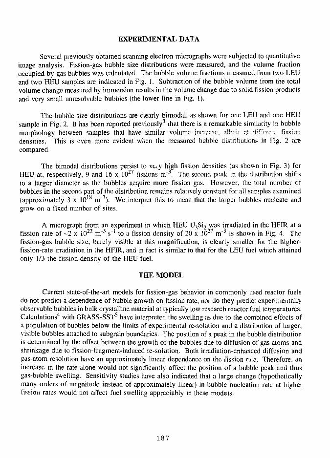
EXPERIMENTAL DATA
Several previously obtained scanning electron micrographs were subjected to quantitativeimage analysis. Fission-gas bubble size distributions were measured, and the volume fractionoccupied by gas bubbles was calculated. The bubble volume fractions measured from two LEUand two HEU samples are indicated in Fig. 1. Subtraction of the bubble volume from the totalvolume change measured by immersion results in the volume change due to solid fission productsand very small unresolvable bubbles (the lower line in Fig. 1).
The bubble size distributions are clearly bimodal, as shown for one LEU and one HEUsample in Pig. 2. It has been reported previously3 that there is a remarkable similarity in bubblemorphology between samples that have similar volume increase, albeir at diffcrrr.: fissiondensities. This is even more evident when the measured bubble distributions in Fig. 2 arecompared.
The bimodal distributions persist to vuy high fission densities (as shown in Fig. 3) forHEU at, respectively, 9 and 16 x 1027 fissions m"3. The second peak in the distribution shiftsto a larger diameter as the bubbles acquire more fission gas. However, the total number ofbubbles in the second part of the distribution remains relatively constant for all samples examined(approximately 3 x 10¹⁸ m"3). We interpret this to mean that the larger bubbles nucleate andgrow on a fixed number of sites.
A micrograph from an experiment in which HEU U3Si2 was irradiated in the HFIR at afission rate of ~2 x 10" m~~ s"! to a fission density of 20 x 10 m~" is shown in Fig. 4. Thefission-gas bubble size, barely visible at this magnification, is clearly smaller for the higher-fission-rate irradiation in the HFIR, and in fact is similar to that for the LEU fuel which attainedonly 1/3 the fission density of the HEU fuel.
THE MODEL
Current state-of-the-art models for fission-gas behavior in commonly used reactor fuelsdo not predict a dependence of bubble growth on fission rate, nor do they predict experimentallyobservable bubbles in bulk crystalline material at typically low research reactor fuel temperatures.Calculations4 with GRASS-SST5 have interpreted the swelling as due to the combined effects ofa population of bubbles below the limits of experimental re-solution and a distribution of larger,visible bubbles attached to subgrain boundaries. The position of a peak in the bubble distributionis determined by the offset between the growth of the bubbles due to diffusion of gas atoms andshrinkage due to fission-fragment-induced re-solution. Both irradiation-enhanced diffusion andgas-atom resolution have an approximately linear dependence on the fission n\c. Therefore, anincrease in the rate alone would not significantly affect the position of a bubble peak and thusgas-bubble swelling. Sensitivity studies have also indicated that a large change (hypotheticallymany orders of magnitude instead of approximately linear) in bubble nucleation rate at higherfission rates would not affect fuel swelling appreciably in these models.
187
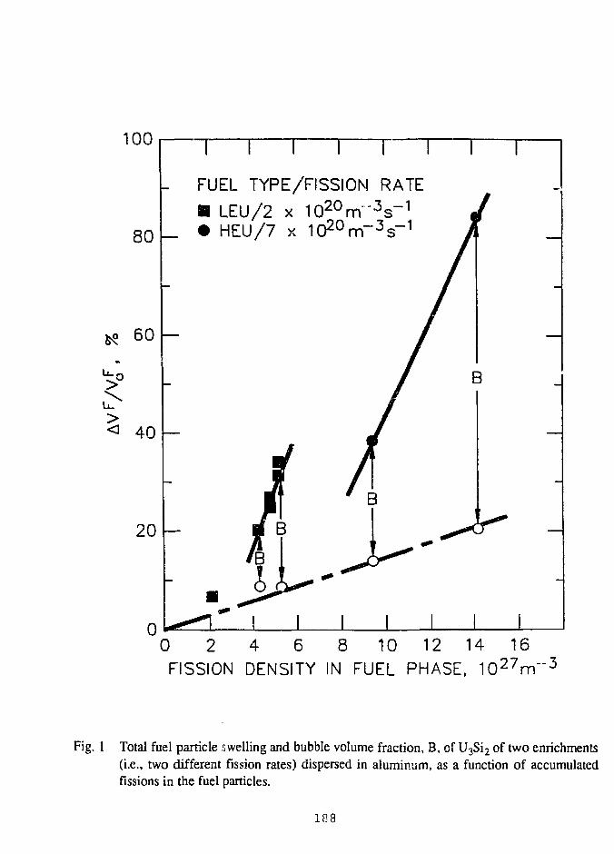
100
80
60
>u.
<
o
40
20
0
T T T
FUEL TYPE/FISSION RATE
B LEU/2 x 10 2 0 r rT 3s- 1
• HEU/7 x 10 2 0 rn- 3 s- 1
0 2 4 6 8 10 12 14 16FISSION DENSITY IN FUEL PHASE, 1 0 2 7 m " 3
Fig. 1 Total fuel particle swelling and bubble volume fraction, B, of U3Si2 of two enrichments(i.e., two different fission rates) dispersed in aluminum, as a function of accumulatedfissions in the fuel particles.
188
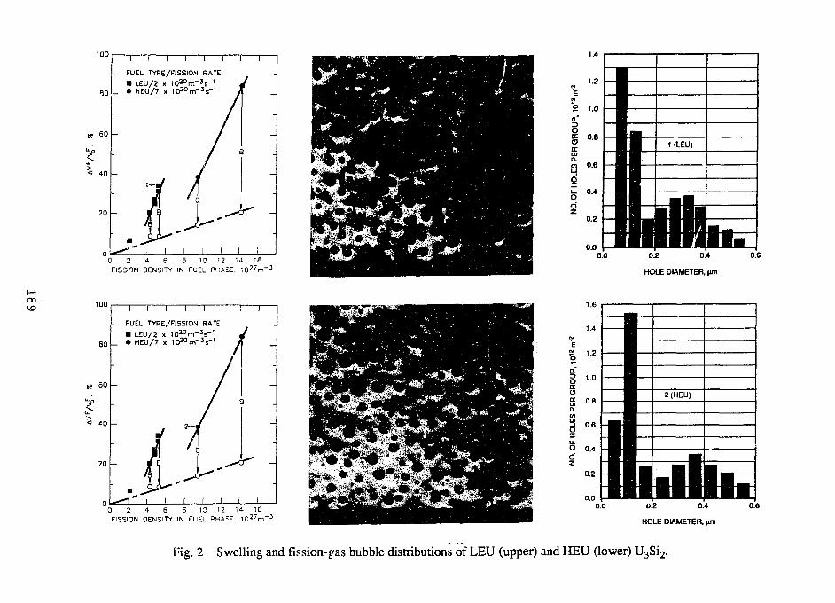
100
L FUEL TYPE/FISSION RATE• LEU/2 x I O 2 o m - 3 s - '
L • HEU/7 x i t f O m ^ '
60
<= 40
20
i i i i i i r
0 2 4 S S 10 12 14 16FISSION OENSITY IN FUEL PHASE. l O ^ r r
1.4
1.2
o 1.0a."
g
ffi
0.2
0.0
BBBBiB '^HiB ^ ^| • •B .MBlB ^TBB 1 •B •B •B •B •BB
•BBBI•BBBIBBBBIBBBBiBBBBIBBBBiMtlTWMBBBBIBBBBIBBBBi
ivBin \ r\ \ ii i i
1 1 h
BBBBiBBBBiBBBBiBBBBiBBBBiBBBBiBBBBiBBBBiBBBBiBBBBiBBBBiBBBBi
1 HB0.0 0.2 0.4
HOLE DIAMETER, (
0.6
CX)100
80
SO
< 40
n r i i i r[• FUEL TYPE/FISSION RATE
, • LEU/2 x 1 0 2 0 r n - V|_ • HEU/7 x l ^ m ' 1
2 0 h
0 2 4 6 8 10 12 14 16FISSION OENSITY IN FUEL PHASE. 1 0 2 7 m " 3
0.00.2 0.4
HOLE DIAMETER. M
Fig. 2 Swelling and fission-^as bubble distributions of LEU (upper) and HEU (lower) U3Si2.
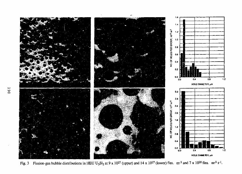
0.0
3.2
2.8
E% 2A
O 20oS 1.6
a
s -0.4
0.D0.0
0.4 0.8
HOLE DIAMETER, (im
:s• —iS1 • •1 '^""
1 ^ ^ ^i r*̂ ^II •I i PI
• • • • 1
• • • •^• • •1• •^ •1
• • • •• • • 1wn.L
• § • •
• • •
•̂ ^^1
• § • ••HHi
•̂ ^̂ 1i r i i I I i i i m
0.4 0.8
HOLE DIAMETER, jun
1.2
Fig. 3 Fission-gas bubble distributions in HEU U3Si2 at 9 x 1027 (upper) and 14 x 1027 (lower) fiss. nr3 and 7 x 10²⁰ fiss. nr3 srl.
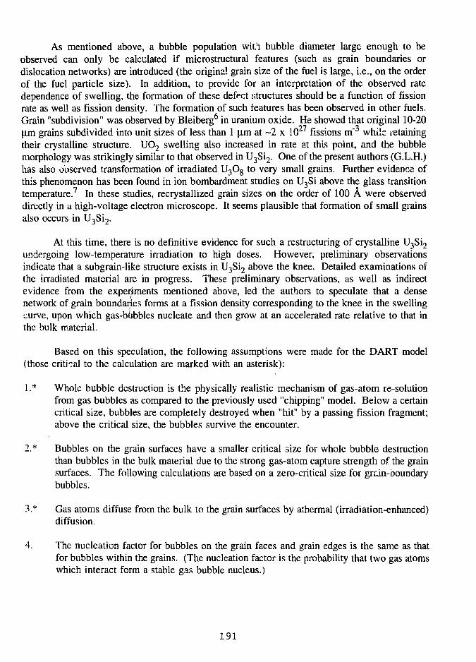
As mentioned above, a bubble population wit'i bubble diameter large enough to beobserved can only be calculated if microstructural features (such as grain boundaries ordislocation networks) are introduced (the original grain size of the fuel is large, i.e., on the orderof the fuel particle size). In addition, to provide for an interpretation of the observed ratedependence of swelling, the formation of these defect structures should be a function of fissionrate as well as fission density. The formation of such features has been observed in other fuels.Grain "subdivision" was observed by Bleiberg6 in uranium oxide. He showed that original 10-20(im grains subdivided into unit sizes of less than 1 |im at ~2 x 1027 fissions m"3 while retainingtheir crystalline structure. UO2 swelling also increased in rate at this point, and the bubblemorphology was strikingly similar to that observed in U3Si2. One of the present authors (G.L.H.)has also observed transformation of irradiated U3O8 to very small grains. Further evidence ofthis phenomenon has been found in ion bombardment studies on U3Si above the glass transitiontemperature.7 In these studies, recrystallized grain sizes on the order of 100 A were observeddirectly in a high-voltage electron microscope. It seems plausible that formation of small grainsalso occurs in U3Si2.
At this time, there is no definitive evidence for such a restructuring of crystalline U3Si2
undergoing low-temperature irradiation to high doses. However, preliminary observationsindicate that a subgrain-like structure exists in U3Si2 above the knee. Detailed examinations ofthe irradiated material are in progress. These preliminary observations, as well as indirectevidence from the experiments mentioned above, led the authors to speculate that a densenetwork of grain boundaries forms at a fission density corresponding to the knee in the swellingcurve, upon which gas-bubbles nucleate and then grow at an accelerated rate relative to that inthe bulk material.
Based on this speculation, the following assumptions were made for the DART model(those critical to the calculation are marked with an asterisk):
1.* Whole bubble destruction is the physically realistic mechanism of gas-atom re-solutionfrom gas bubbles as compared to the previously used "chipping" model. Below a certaincritical size, bubbles are completely destroyed when "hit" by a passing fission fragment;above the critical size, the bubbles survive the encounter.
2.* Bubbles on the grain surfaces have a smaller critical size for whole bubble destructionthan bubbles in the bulk material due to the strong gas-atom capture strength of the grainsurfaces. The following calculations are based on a zero-critical size for grain-boundarybubbles.
3.* Gas atoms diffuse from the bulk to the grain surfaces by athermal (irradiation-enhanced)diffusion.
4. The nucleation factor for bubbles on the grain faces and grain edges is the same as thatfor bubbles within the grains. (The nucleation factor is the probability that two gas atomswhich interact form a stable gas bubble nucleus.)
191
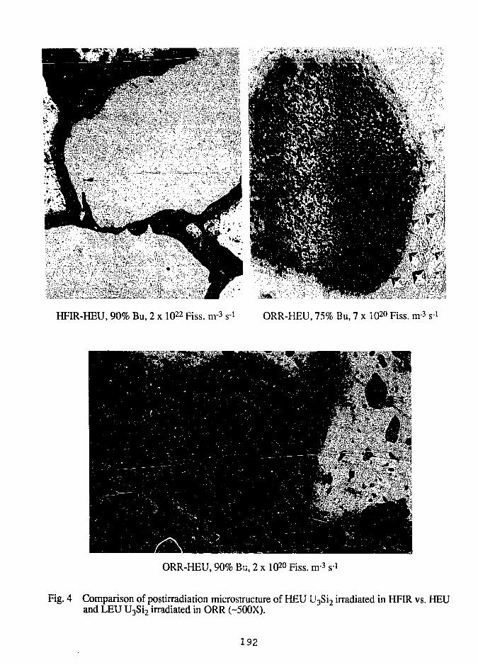
HFIR-HEU, 90% Bu, 2 x 1Q22 Fiss. m-3 s 1 ORR-HEU, 75% Bu, 7 x 10²⁰ Fiss. nv* s 1
ORR-HEU, 90% Bu, 2 x 1Q20 Fiss. m-3 s-i
Fig. 4 Comparison of postirradiation microstructure of HEU U3Si2 irradiated in HFIR vs. HEUand LEU U3Si2 irradiated in ORR (-500X).
192
(.o
10'22i i i i i i i
D DART „ . -87 - 3
O DATA 9 X 1 ° m
0.1 0.2 0.3 0.4 0.5 0.6 0.7 0.8 0.9 1.0 1.1 1.2
Bubble Diameter (/zm)
1022
i i r r i i i i
• DART 27 -3
O DATA l D X l ° m
O.BSfim grains
,,0.75/im grains
'.O,
o o.o
I ' I I I
0.1 0.2 0.3 0.4 0.5 0.6 0.7 0.8 0.9 1.0 1.1 1.2
Bubble Diameter (/zm)
(a) (b)
Fig. 5 Comparison of measured and calculated bubble distributions in U3Si2 at 9 x 1027 and 16 x iO27 fissions nr3. The effects ofboth fission density and grain size on the position of the second mode of the distribution are evident.
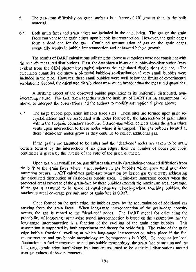
5. The gas-atom diffusivity on grain surfaces is a factor of 104 greater than in the bulkmaterial.
6.* Both grain faces and grain edges are included in the calculation. The gas on the grainfaces can vent to the grain edges upon bubble interconnection. However, the grain edgesform a dead end for the gas. Continued accumulation of gas on the grain edgeseventually results in bubble interconnection and enhanced bubble growth.
The results of DART calculations utilizing the above assumptions were not consistent withthe recently measured distributions. First, the data show a bi-modal bubble-size-distribution (veryevident from the SEM photomicrographs) whereas the calculated distributions did not. (Thecalculated quantities did show a bi-modal bubble-size-distribution if very small bubbles wereincluded in the plot. However, these small bubbles were well below the limits of experimentalresolution.) Second, the calculated distributions were much broader than the measured quantities.
A striking aspect of the observed bubble population is its uniformly distributed, non-interacting nature. This fact, taken together with the inability of DART (using assumptions 1-6above) to interpret the observations led the authors to modify assumption 6 given above:
6.* The iarge bubble population inhabits fixed sites. These sites are formed upon grain re-crystallization and are associated with nodes formed by the intersection of grain edgeswithin the subgrain boundary structure. Fission-gas which collects along the grain edgesvents upon intersection to these nodes where it is trapped. The gas bubbles located atthese "dead-end" nodes grow as they continue to collect additional gas.
If the grains are assumed to be cubes and the "dead-end" nodes are taken to be graincorners formed by the intersection of six grain edges, then the number of nodes per cubiccentimeter is given by the inverse of the cube of the grain diameter.
Upon grain recrystallization, gas diffuses athermally (irradiation-enhanced diffusion) fromthe bulk to the grain faces where it accumulates in gas bubbles which grow until grain-facesaturation occurs. DART calculates grain-face saturation by fission gas by directly addressingthe calculated distribution of fission-gas bubble sizes. Grain-face saturation occurs when theprojected areal coverage of the grain-face by these bubbles exceeds the maximum areal coverage.If the gas is assumed to be made of equal-diameter, closely-packed, touching bubbles, themaximum areal coverage per unit area of grain-face is 0.907.
Once formed on the grain edge, the bubbles grow by the accumulation of additional gasarriving from the grain faces. When long-range interconnection of the grain-edge porosityoccurs, the gas is vented to the "dead-end" nodes. The DART model for calculating theprobability of long-range grain-edge tunnel interconnection is based on the assumption that thflong-range interconnection is a function of the swelling of the grain edge bubbles. Thisassumption is supported by both experiment and theory for oxide fuels. The value of the grainedge bubble fractional swelling at which long-range interconnection takes place if the fuelmicrostructure and gas bubble morphology are homogeneous is 0.055. To account for localfluctuations in fuel microstructure and gas bubble morphology, the grain-face saturation and thelong-range grain-edge interlinkage fractions are assumed to be statistical distributions aroundaverage values of these parameters.
194
The points connected by solid curves in Fig. 5 show the results of DART bubble-sizedistribution calculations at fission densities of 9 x 1027 m"3 and 16 x 1O27 m"3 when the "dead-end" nodes are included in the analysis and a recrystallized grain size of 0.65 |im is utilized.Grain recrystallization was taken to occur at a fission density of 2.5 x 1027 m~3. Also shown inFig. 5 are data obtained from SEM micrograph*, of the irradiated material. The calculated bubbledistributions for bubble sizes below 0.4 (im diameter are due to bubbles on the grain faces andthe grain edges. The calculated points at bubble diameters of about 0.4 (im [Fig. 5(a)] and0.6 |0,m [Fig. 5(b)], respectively, are due to the accumulated gas in the "dead-end" nodes.Currently, DART only calculates the growth of an average-si1 .• node and does not account forthe experimentally observed distribution of node-bubble sizes. In addition, the observed densityof node-bubbles appears to decrease from about 3.6 x 10¹⁸ m~3 at a fission density of 9 x 1027
m~3 to about 2.4 x 10¹⁸ m"3 at a fission density of 16 x 1027 m"3. This phenomenon may be dueto smailer node bubbles being consumed by larger node bubbles and is not included in the DARTcalculations. Consequently, using a 0.65 [im recrystallized grain size, which corresponds to anode density of 3.6 x 10 l s m~3, the calculated size of the node-bubbles at 16 x 1027 m~3 will beunderpredicted, as seen in Fig. 5(b).
Also shown by the dashed line in Fig. 5(b) are the DART-calculated distributions utilizinga 0.75 u,m recrystallized grain size, which corresponds to a node density of 2.4 x 10 m"". Asis shown in Fig. 5(b), a shift in recrystallized grain size from 0.65 |lm to 0.75 [J.m shifts thenode-bubble diameter at 16 x 10 m from about 0.6 |im to about 0.7 |j.m. Given the aboveconsiderations, the DART calculations shown in Fig. 5 follow the trends of the observed bubble-size distribution in irradiated U3Si2 as a function of burnup and, as such, provide plausiblephysical interpretation of the irradiation behavior. More detailed calculations may be possiblewhen the actual subgrain morphology in the samples can be quantitatively determined.
CONCLUSIONS AND APPLICATION
The current version of DART provides an improved description of the irradiation behaviorof U3Si2 dispersion fuel. Specifically, the observed fission-gas bubble morphology in samplesirradiated in the ORR up to a fission density of 16 x 1027 nT3 over a fission rate range of 2-7x 10 m s" can now be more accurately modeled. Recent irradiation experiments with U3Si2
in the HFIR at much higher fission rates (up to 2 x 10²² m'V 1 ) afford further validation of themodel.
The improvements in the model increase the confidence in predictions of irradiationbehavior outside the parameter range for which test results are available. The model can beapplied to assess fuel swelling behavior and change in fuel thermal conductivity for both very-high-flux and low-flux reactors.
Because of the more realistic description of fission-gas behavior, the model can beextended to predict off-normal fuel behavior with greater confidence.
195
REFERENCES
1. J. Rest and G. L. Hofman, "Fundamental Aspects of Inert Gasses in Solids,"S.E. Donnelly and J.H. Evans Ed., Plenum Press, 443 (1991).
2. J. Rest and G. L. Hofrnan, presented at 15th ASTM Symposium on Effects of Radiationon Materials, Nashville, TN (June 17-21, 1990).
3. G. L. Hofman, "The General Evaluation of the Irradiation Behavior of Dispersion Fuels,"presented at the 1991 International Meeting on Reduced Enrichment for Research andTest Reactors, Jakarta, Indonesia (November 4-7, 1991).
4. J. Rest et al., "Effects of Radiation on Materials, 14th International Symposium (Vol. II),ASTM STP 1046, N. H. Packan, R. E. Stoller, and A. S. Kumer, Eds., American Societyfor Testing and Materials, Philadelphia, PA, 789 (1990).
5. J. Rest, "GRASS-SST: A Comprehensive Mechanistic Model for the Prediction ofFission-Gas Behavior in UO2-Base Fuels During Steady-State and Transient Conditions,"NUREG/CR-0202, ANL-78-53, Argonne National Laboratory Report, Argonne, IL (1978).
6. M. L. Bleiberg, R. M. Berman, and B. Lustman, Symposium on Radiation Damage inSolid and Reactor Materials, Proc. Series, IAEA, Venice, 319 (1963).
7. R. C. Birtcher and L. M. Wang, presented at 7th International Conference on Ion BeamModification of Materials, IBMM90, Knoxville, TN (September 9-14, 1990).
196
S E S S I O N VI
September 30;, 1992
HEU AND LEU FUEL CYCLE
Chairman:
J. Mota(Euratom Supply Agency, Belgium)
197
External Research Reactor Fuel Cycle:BACK-END OPTIONS
Gerhard. J. GruberNUKEM GmbH
W-8755 Alzenau, Germany
ABSTRACT
The U.S. Deparment of Energy still has not renewed its Off-Site FuelPolicy for the acceptance of spent foreign Research Reactor Fuels.
Two European companies offer reprocessing services under thecondition of waste return to the country of origin. Direct disposal ofspent RR Fuels is only a very restricted potential national optionwhich has not yet proven its realisation.
Other back-end options are not available for the time being.
INTRODUCTION
NUKEM as an international engineering and trading company is working on nuclearand non-nuclear fields.
Its Fuel Cycle Services Division, located in the company's headquarter inAlzenau, has been successfully offering its services on the External ResearchReactor (RR) Fuel Cycle for more than twenty years.
At the beginning of 1989 - when U.S. Department of Energy (US-DOE) hadsuspended to accepting foreign RR Fuels - NUKEM started to assist concerned RRoperators to close the back-end of their fuel cycles.
Since then NUKEM has helped at least three German reactors to stay operationalby establishing storage and reprocessing agreements for spent RR Fuels with AEA.
This is an update of the back-end options for the RR Fuel Cycle.
US-DOE (U.S. Department of Enemy)
Another year passed by and a new Off-Site Fuel Policy has not yet beenannounced by the U.S. government. Now it's already 3 years and 9 months sinceU.S.-DOE had suspended the acceptance of foreign RR Fuels for reprocessing.
199
What was the status when NUKEM reported at the meeting in Jakarta lastNovember?
US-DOE had published a proposed FONSI ("Finding of \ 'o Significant Impact") -including an Environmental Assessment (AE) - in the Fe •' - : Register (FR) in May1991.
This FONSI stated that
a) transportation of spent RR Fuel on the high seas, in U.S. ports and on the highwayand
b) reprocessing of the Fuel at the potential sites - which are the Savannah River Site(SRS) and Idaho National Engineering Laboratory (INEL) -
would not significantly affect the quality of the human environment within themeaning of the National Environmental Policy Act (NEPA) of 1969.
Also the potential reprocessing impacts at either site would be insignificant. Andthe acceptance of U.S. origin Fuel from abroad serves non-proliferation interests byremoving weapon grade material and is therefore consistent with the Atomic EnergyAct.
Major substantial comments on that publication in the FR were received byUS-DOE from members of U.S. Congress and environmental groups. Most of thecomments were seriously requesting a "full blown" Environmental Impact Statement(EIS).
It was up to US-DOE to decide straight forward for renewing the reprocessingpolicy, following up the nuclear non-profileartion aspect.
Or to perform an EIS which was predicted to take at least 2 years followed againby the mandatory publication procedure with a lot of uncertainties involved includingpotential law suits.
What has happened within the US-DOE since Nov. 91 in respect to acceptingspent Fuel again?
The subject was obviously given a low priority at US-DOE. No announcement wasmade about extending its suspended Fuei policy and no decision for an EIS has beentaken so far.
In April 1992, Admiral Watkins, the secretary of US-DOE, announced his decisionto phase out the reprocessing of spent Fuel as soon as possible because the US nolonger has the need to reprocess spent Fuel in order to recover the HEU. The coldwar was over and President Bush decided to reduce the nuclear weapons stockpile.
That means US-DOE will have to find solutions for storage of the Fuel.
200

This leads to new questions for foreign RR operators such as:
- Will US-DOE come into a position to accept spent foreign Fuels for final storage?
- If yes, when and under what conditions?
- How will a possibly new government administration after the election treat thatsubject?
- What priority will be given to the profileration aspect?
AEA TECHNOLOGY. Great Britain
AEA, as a marketing unit of UKAEA (United Kingdom Atomic Energy Authority) issuccessfully offering reprocessing services for foreign spent WITR-HEU-Fuels.
NUKEM has arranged for two reprocessing contracts and coordinated the relevantshipments to Dounreay in Scotland all within the last year.
These Fuels will be reprocessed in the currently running campaign.
During an international RR operators meeting hosted by AEA in Dounreay in June1992, AEA offered reprocessing services for future campaigns.
Due to the fact that there is no further domestic need for such services in Britain,future campaigns can only be based on a sufficient foreign demand.
To run the plant economically and to keep it operational, AEA needs to reprocessat least 1800 kg total metal per year over a three years period. This numbercorresponds to about 500 fuel elements/assemblies.
Relevant contracts for reprocessing do have to contain a return of waste clause.Under this clause the waste generated from reprocessing will be returned either inform of "Intermediate Level Residue (ILR)" directly arising from reprocessing or as anequivalent quantity of "High Level Residue (HLR)" if appropriate.
Customers outside EURATOM will need prior U.S. approval (so-called MB-10procedure) for the transfer and retransfer of the U.S. origin material to and from theU.K. But as far as we learned from informal talks the U.S. will not prevent customersfrom having their spent HEU-Fuels reprocessed in Britain or France.
AEA is also reviewing the possibility of treating spent LEU-silicide-Fuels andTRIGA-(UZrHx)-Fuels as there is currently also no final back-ena option available on
the market for these types of Fuels.
201
COGEMA. France
After a period of technical and commercial review COGEMA's option to close theback-end of the Fuel Cycle for MTR-HEU-Fuel became definite within last year.
In May 1992, at tr;e occassion of a RR operators meeting in Dresden COGEMAannounced officialy its readiness to negotiate reprocessing contracts for MTR-HEUelements individually with interested operators.
The basic conditions were said to be comparable with those of AEA, Dounreay.
That means e. g.:
- return of waste will be mandatory- recovered uranium cannot be re-enriched and will be returned to the
customer for a possible re-use.
But the time prospects are different to AEA's:
Starting in 1994, COGEMA could accept spent MTR-HEU-Fuels for advancestorage. Domestic and foreign Fuel would then be collected to a batch of at least 1000elements and reprocessed at a time convenient to COGEMA.
DIRECT DISPOSAL OPTION
Direct Disposal of spent RR Fuels is to be considered as a national back-endoption for spent HEU-Fuels, at least in Germany.
Germany has an advanced program for Direct Disposal of spen LWR fuels.
In 1991 the German Ministry for Research and Developement (BMFT) started toinvestigate the possibility of whether this route can also be taken for spent HEU-Fuels
The concept is based on medium term dry storage of the Fuels in casks either onsite or in a national repository. Casks are developed and have only to be speciallylicensed.
Thereafter the Fuel has to be repacked in the Pi!ot-Gondition!ng-Plant (PKA) andfinally disposed under earth.
The iong term behaviour of the Fuel is still being investigated and the Safeguardsquestions are under discussion.
202
OTHER OPTIONS
Russian companies were approached by different parties and through differentchannels without success.
Even foreign HEU-Fuels of Russian origin are not accepted for reprocessing.
Other options for closing the back-end of the RR Fuel Cycle are not known to us.
SUMMARY
The back-end of the RR Fuel Cycle continues to be the cause of great concern.
US-DOE still has not announced a new Off-Site Fuel Policy. AEA Technology andCOGEMA offer reprocessing services with the condition of waste-return to the countryof origin.
Direct Disposal is a potential option for only a very limited number of countries.Other options are currently not available.
Under these circumstances most of the RR operators worldwide are withoutback-end solution.
MUKEM will continue to watch the development on the Fuel Cycle in order to givebest advice and assistance to our customers - as in the past.
203
THE RE-USE OF HIGHLY ENRICHED URANIUM (HEU)REPROCESSED IN EUROPE
Hans MullerNUKEM GmbH
W-8755 Alzenau, Germany
ABSTRACT
After the shut-down of the U.S. reprocessing plants for spentresearch fuel at Savannah River and Idaho Falls research reactoroperators outside the US have been facing the dilemma to closetheir fuel cycle elsewhere. In Europe the British AEA and the FrenchCogema have decided to offer reprocessing of spent researchreactor fuel in order to close the existing gap.
The re-use of reprocessed HEU in Europe strongly depends on thepreparedness of European manufacturers of fuel elements forresearch reactors to accept the reprocessed uranium as basematerial for their production.
INTRODUCTION
1. Status of Reprocessing in Europe
AEA, Dounreay having a reprocessing plant available is at the momentreprocessing several hundreds of spent research reactor fuel elements with HEU in afirm campaign. In an early June 1992 symposium at Dounreay AEA offered topotential customers world-wide continuation of reprocessing of spent research reactorfuel for three years at firm conditions and starting in 1993.
The French Cogema has also announced that they will offer acceptance andreprocessing of spent research reactor fuel containing HEU after 1994 in an alreadyexisting reprocessing plant which has to be adapted.
2. The Re-Use of reprocessed HEU
As is known, research reactor fuel with an original U-235 content of 93 % has -after a burn up of 50 % - a final enrichment between 70 to 80 % U-235.
Since U 235 contents between 70 and 80 % are odd ones (Research reactoroperators have licensed their fuel either to 19.75 or 90 to 93 % U-235), there is nodemand for the direct use of such a fuel. Only DIDO-reactors can utilize these oddU-235 contents in a second fuel cycle.
204
In consequence thereof the reprocessed HEU - at least what AEA concerns - will beblended down to LEU with a U-235 content of 19.75 % for further use as silicide fuel.This procedure is in line with the implemented US policy of Reducing Enrichment inResearch and Test Reactors (RERTR).
3. Comparison of the Specification of so-called "virgin" LEU/HEU withreprocessed HEU
Reprocessed HEU contains increased amounts of U-232 and U-236 in comparisonwith so-called "virgin" LEU/HEU until now provided to research reactors by the USDepartment of Energy (DOE). The values of U-232 contained in the spent HEU are inthe range of some 10 ppb and U-236 values are in the range of 6 to 12 % dependingupon the neutron flux particular to the reactor type. A 19.75 % U-235 enricheduranium obtained by blending of reprocessed HEU will contain values between 1 and10 ppb for U-232 and a U-236 content of 3 to 4 %.
In papers presented by AEA's Colin McColm at the 14th RERTR meeting in Jakartain 1991 and at the Uranium Institute Meeting in London on September 10, 1992 AEAclearly declared that AEA has the experience and is licensed to handle thereprocessed HEU and blended HEU for further fuel element production.
For research reactor operators increased U-236 contents should not be a problemsince U-236 behaves about in the same manner to that of U-238, i. e. it has a highneutron capture cross section with the resulting parasitic effect on neutrons.
Thus, for the re-use of the LEU obtained by blending of reprocessed HEU it ismandatory that reprocessors of spent research reactor fuels, manufacturers of freshfuel and the research reactor operators arrive to an agreement about the relevantspecifications for this LEU.
At the RERTR meetings in Newport (1990) and Jakarta (1991) I presentedproposals to establish common specificatior- of LEU and HEU in the form of metal withthe target to standardize and simplify the existing numerous specifications. At thesame time I challenged the existing term "virgin" HEU supplied by DOE.
Until then manufacturers of research reactor fuels accepted freshly supplied HEUfrom DOE as a virgin LEU without checking, for example, transuranic and fissionactivities.
In connection with the re-use of LEU with U-235 contents of 20 and 35 % from aZero-Experiment in Europe, NUKEM started to clarify the acceptance of this fuel. Westarted to look closer to this fuel from its delivery from the US until after itsre-availability after termination of the O-Experiment.
In order to allow for a comparison of the so-called "virgin" US HEU I show you astable 1 the revised DOE specifications Standard Purity for HEU. It shows as typicalvalues for U-234 1.5 % and for U-236 0.54 %. No mention is made to the content ofU-232 since in former times nobody showed interest for this content.
205
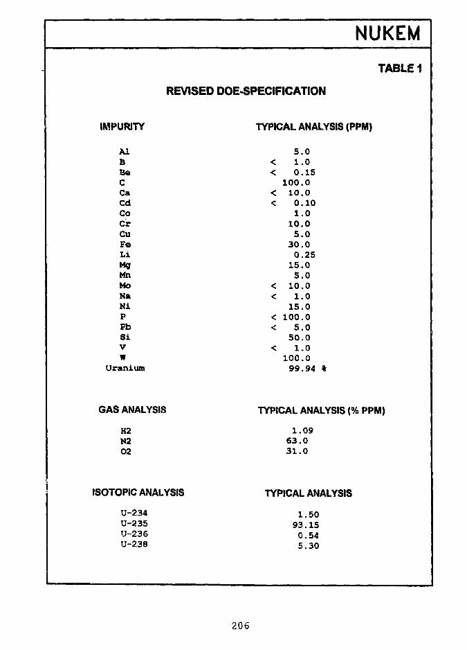
NUKEM
TABLE 1
REVISED DOE-SPECIFICATION
IMPURITY
A lBBeCCaCdCoCrCuFeL iMgMnMoNaMiPPbS iVW
Uranium
GAS ANALYSIS
H2N202
ISOTOPIC ANALYSIS
U-234U-235U-236U-238
TYPICAL ANALYSIS (PPM)
5 . 0< 1.0< 0.15
100.0< 10.0< 0.10
1.010.0
5 . 030.0
0.2515.0
5 . 0< 10.0< 1.0
15.0< 100.0< 5.0
50.0< 1.0
100.099.94 %
TYPICAL ANALYSIS (% PPM)
1.0963.031.0
TYPICAL ANALYSIS
1.5093.150.545.30
206
As table 2 I show you again the range of values for U-234 (from 0.5 to 1.14 %}and for U-236 (from 0.01 to 1.57 %) which had determined as former fuel elementmanufacturer.
Table 3 shows you figures on Plutonium-values which have been found in LEUmetal supplied by DOE.
4. Conclusion
As can be easily noted from tables 1 to 3, HEU supplied by DOE never was "virgin".From the values given for U-236 and Plutonium one can come to the conclusion thatDOE well used reprocessed uranium in their enrichment process for fresh HEU.
Since we have started in Europe with the reprocessing of spent HEU fuel we havealso consequently to deal with the re-introduction of this fuel into the fuel cycle.
We can confirm AEA's figures in the paper "An Assessment of the Use of RecycledUranium in Low Enriched Research Reactor Fuel" which was presented at theUranium Institute Annual Symposium on September 11, 1992.
The conclusion of this paper is that the use of recycled uranium to fuel LEUresearch reactors should therefore be considered as presenting an opportunity to costeffectively utilize an otherwise valueless resource.
Still unclear matters such as specification for the recycled ar.d blended LEU should1 -9 solved with the participation of reprocessors, fuel eiement fabricators and researchreactor operators.
NUKEM, being a company active in the external fuel cycle for research and powerreactors is ready to assist you in that respect as in the past.
207
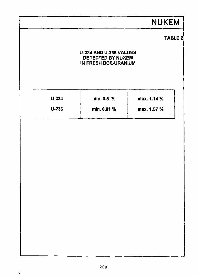
U-234 AND U-236 VALUESDETECTED BY NUKEM
IN FRESH DOE-URANIUM
NUKEM
TABLE 2
U-234
U-236
min. 0.5 %
min. 0.01 %
max. 1.14%
max. 1.57%
208
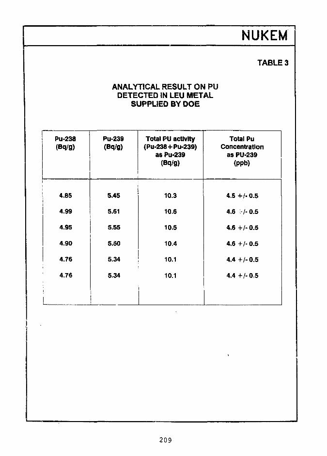
ANALYTICAL RESULT ON PUDETECTED IN LEU METAL
SUPPLIED BY DOE
NUKEM
TABLE 3
Pu-238(Bq/g)
ji
4.85
4.99
4.95
4.90
4.76
4.76
Pu-239(Bq/g)
5.45
5.61
5.55
5.50
5.34
5.34
Total PU activity(PU-238+Pu-239)
as Pu-239(Bq/g)
10.3
10.6
10.5
10.4
10.1
10.1
Total PuConcentration
as PU-239(ppb)
4.5+/-0.5
4.6 -/-0.5
4.6 +/-0.5
4.6 +/- 0.5
4.4 +/-0.5
4.4 +/-0.5
209
RECYCLING OF REPROCESSED URANIUMFROM RESEARCH REACTORS
S. Bouchardy and J.F. PautyCOGEMA, Enrichment Branch
78140 Velizy Villacoublay, France
ABSTRACT
Research reactor fuels were already reprocessed in France in the 1970s,and their reprocessing is expected to resume shortly. The uraniumrecovered still contains a very high enrichment which should be utilized.The recycling of this reprocessed uranium (RepU) in the form of 19-75%U metal is one attractive method proposed by COGEMA.
This paper reviews the processes for making uranium metal applied atPierrelatte, either from UF6 or from recycle materials. It describes thecharacteristics of the reprocessed uranium and the way in which COGEMAplans to recycle it in its facilities. Problems of radiation protection arediscussed, as well as the research and tests under way, which are intendedto confirm the feasibility of this solution.
INTRODUCTION
The Pierrelatte facilities were commissioned about thirty years ago to produce highlyenriched uranium metal for the French Defence Department. UFg is enriched bygaseous diffusion. The metal is prepared by the URE facilities (Recycle andProduction Unit). Designed from the outset to recycle fabrication scrap from theDefence Department by nitric dissolution, these facilities are basically ideal forconverting the uranyl nitrate produced by reprocessing into uranium metal.
For the past ten years, these facilities also recycle mstal from the fabrication scrapreceived from the CERCA fuel fabrication plant. They also carry out chemicalconversions to the chemical forms of the oxide (U3Og) or metal for other clients,irrespective of the isotopic uranium content.
These installations were not initially designed to recycle, irradiated materials.Problems of radiation protection specific to RepU are currently being examined (seesection entitled Evolution of RepU during recycle).
210
THE URE FACILITY(Recycle and Production Unit)
Two main process lines, the Dry Process (VS) and Wet Process (VH) are used indifferent modular facilities designed to operate up to the highest U 235 enrichments,above 93% (Figure 1).
a Dry process
This process leads to the production of the metal from UF6-
Highly-enriched UFe is first reduced in the presence of hydrogen to UF4. Bycalcium reduction and remelting, the metal is then cast into 5 kg ingots. The qualityof the metal obtained easily meets the standards of fuel fabricators for researchreactors.
b Wet process
This process was developed for two purposes:
• to obtain a very pure final product,• to recycle production scrap from the Defence Department.
The process was also subsequently used to recover material from fuel fabricationscrap.
The scrap, metal U or oxides after possible roasting, or alloys (UA1X, U3Si2) areconverted to uranyl nitrate. Other uranium-bearing chemical forms demand morecomplex treatment. The solution obtained generally undergoes one, or sometimestwo purification cycles (TBP solvent treatment).
From uranyl nitrate, the main steps of the process are:
• precipitation in the form of ADU,• calcination in the form of U3O8,• reduction in the form of UO2,• fluoridation to UF4.
The UF4 thus produced returns to the dry process for metal production by calciumreduction.
For several years, COGEMA, from its own facilities, has been delivering supplies ormaterial recycle services for research reactors.
211
REPROCESSED URANIUM
After reprocessing, RepU in the form of uranyl nitrate can be introduced into the wetprocess, normally after the purification step. However, the chemical impurity contentmay require a purification cycle.
Reprocessed uranium displays differences from enriched uranium obtained fromnatural uranium.
From the isotopic standpoint, two artificial radioisotopes are present after irradiation inthe reactor, U 236 and U 232.
a Uranium 236
Uranium 236 is a neutron absorbent and may represent a handicap for some users.
However, its presence has no effect for chemical conversion treatments.
b Uranium 232
By contrast, uranium 232, by radioactive filiation, gives Bi 212 and Tl 208, bothhigh-energy gamma emitters which raise specific problems of radiation protection(Figure 2).
U 232 is formed in the reactor in complex ways (Figure 3) requiring detailedmodelling to calculate the isotopic distribution.
Pre-irradiation storage time, and initial impurity content (U 236, thorium) areimportant parameters for the U 232 production rate.
By natural decay, U 235 (93% in fresh metal) and U 234 (more than 1% in freshmetal) produce an accumulation of Pa 231 and Th 230 in the metal. Underirradiation, these two elements yield U 232 (via Pa 232).
Storage time after irradiation is also important for the formation in the reactor of Pu236, which also yields U 232 by radioactive decay (half-life 2-8 years).
Past reprocessing experience of research reactor fuels and calculations show that the U232 content can be positioned in the range between 2 and 12 ppb.
c Transuranics and fission products
The uranyl nitrate produced by reprocessing also contains traces of fission productsand transuranium elements.
212
By taking the RepU specifications of electric power reactors as a reference, andassuming that the average value is 50% of the specified limit, the following activitiescan be considered as representative:
transuranics: 125 Bq/gU (alpha activity Pu, Am, Np, Cm),• fission products: 9250 Bq/gU (beta/gamma activity).
d Impurities
Non-radioactive chemical impurities are also present in the nitrate.
The total, normally less than 500 ppm/U, is acceptable. However, a sufficiently highlevel of impurities may demand a solvent purification step to make the product meetfuel fabrication standards.
RECYCLING PROPOSED
The RepU recovered has considerable residual enrichment, 70 to 80%, which shouldbe utilized.
COGEMA has basically discarded the alternative of fluorination followed by re-enrichment. The high U 236 content of this material would in fact durably pollute thesubsequent production of the enrichment cascades.
COGEMA proposes to dilute this material to produce a uranium that can be used inresearch reactors, with a standard enrichment of 19-75%.
The mixing of R kg of U from RepU with a residual U 235 content of Nr, with D kgU with Nd content yields P kg U product usable at Np content (Np = 19-75%).
The dilution factor f is defined by:
P Nr - Ndf = — =
R Np - Nd
Thus for 1 kg U/RepU with Nr = 80% diluted with depleted uranium with Nd =0-30%, we obtain P = 4-098 kg U with Np = 19-75%.
This dilution factor of about 4 commensurately reduces all the contents of potentiallyproblematic elements.
By proceeding with pure dilution nitrate, the U 232, U 236, transuranics and fissionproducts contents are divided by this factor f. The chemical impurity contents are alsoreduced. The factor varies according to the level of each element present in thedilution uranium.
213
Dilution with a more enriched uranium j'ields a larger quantity of product P and hencewith higher dilution (Table 1).
Nd
reprocessed Ureprocessed Ureprocessed U
—
80%70%60%
Table 1Dilution factor f
Uranium used for dilutiondepleted U natural U0-30% 0-74%
4-103-583-07
4163-64311
EU50%
5084-413-73
MEU10%
7-186-155-13
for final product with Np = 19-75%
With 5% uranium, for example, the dilution factor is 5-085. However, an economicapproach on an individual case basis should help to decide whether the additionalmaterial gained justifies the use of a more costly dilution material.
At all events, it is more interesting to perform this dilution in the reprocessing plantwhere it raises no problems. The beneficial effect of dilution is advantageous for allthe subsequent steps in recycling, beginning with RepU transport, recycling facilities,fuel fabrication plant, storage and handling at the reactor site. The final isotopicadjustment is made at the head end of the metal conversion plant
EVOLUTION OF RepU DURING RECYCLE
COGEMA has already accumulated considerable experience ir. recycling reprocesseduranium from nuclear power plant fuels. Conversion of RepU urai yl nitrate from theLa Hague plants to UF4 or U3O8 is routine practice at Pierrelatte. COGEMA isthoroughly familiar with developments in the contents of fission products andtransuranium elements.
• Virtually 100% of the transuranics accompany the uranium to the oxide and UF4steps.
• A maximum of 80% of the fission products are found in the uranium up to UF4.
The calcium reduction step (which is not carried out on RepU from power reactors)must be subjected to tests. The cautious assumption made today is that there ispractically no elimination of transuranium elements in the slag, and that at least 50% of
214
the fission products should be found in the slag or the off gases from calciumreduction
The case of U 232 daughters is more complex. Theoretically, perfect separation ofthe products of the U 232 decay chain should ensure zero activity after completereprocessing. With the progressive reconstruction of the chain, 90% of the activity ofthe daughters is again reached after eight years (four half-lives).
In practice, thorium, the First link in the decay chain, may be separated imperfectly,and the time elapsing between reprocessing and refuelling in the reactor could amountto a few years. The presence of a gaseous radionuclide, radon 220, in the chainfurther complicates tine calculations.
Thus it is considered with caution that the gamma emitters bismuth 212 and thallium208 are at equilibrium with uranium 232.
Table 2 summarizes the changes in RepU through the different steps in recycling.
Table 2Anticipated changes in characteristics of
RepU in recycling steps
isotopic content:• U 235 (%)• U 236 (%)• U 234 (%)• U 232(ppb)dLQVuy.• FP (Bq/gU)• TU (Bq/gU)chemicalimpurities (ppm)
after reprocessingspecification
----
18,500250
3000
after dilution (expected values uranyl nitrate
60 to 80I to l50-5 to 112 to 12
9250125
500
19-750-25 to 3-75013 to 0-280-5 to 3
230030
purificationpossible
f = 4)metal
19-750-25 to 3-75013 to 0-280-5 to 3
<100030
fuel standard
215
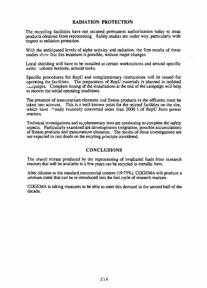
RADIATION PROTECTION
The recycling facilities have not secured permanent authorization today to treatproducts obtained from reprocessing. Safety studies are under way, particularly withrespect to radiation protection.
With the anticipated levels of alpha activity and radiation, the first results of thesestudies show that this treatment is possible, without major changes.
Local shielding will have to be installed at certain workstations and around specificunits: column bottoms, annular tanks.
Specific procedures for RepU and complementary instructions will be issued foroperating the facilities. The preparation of RepU materials is planned in isolatedcampaigns. Complete rinsing of the installations at the end of the campaign will helpto recover the initial operating conditions.
The presence of transuranium elements and fission products in the effluents must betaken into account. This is a well-known point for the related facilities on the site,which have -^eady routinely converted more than 2000 t of RepU from powerreactors.
Technical investigations and supplementary tests are continuing to complete the safetyaspects. Particularly examined are developments (migration, possible accumulation)of fission products and transuranium elements. The results of these investigations arenot expected to cast doubt on the recyling principle considered.
CONCLUSIONS
The uranyl nitrate produced by the reprocessing of irradiated fuels from researchreactors that will be available in a few years can be recycled in metallic form.
After dilution to the standard commercial content (19-75%), COGEMA will produce auranium metal that can be re-introduced into the fuel cycle of research reactors.
COGEMA is taking measures to be able to meet this demand in the second half of thedecade.
216
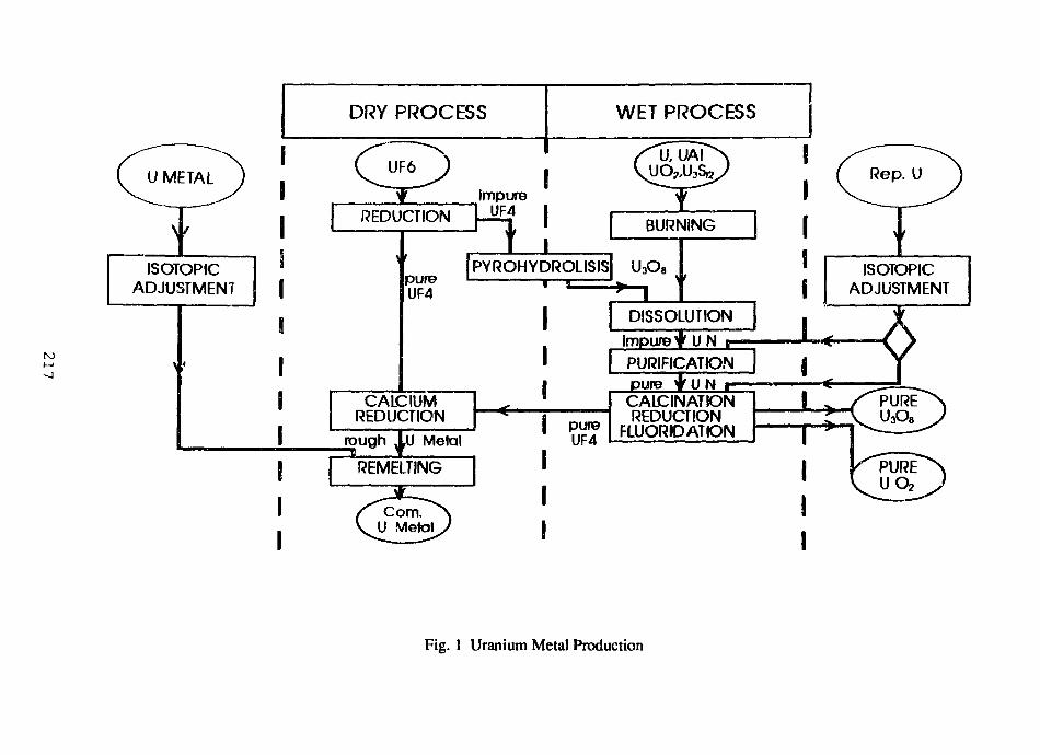
ISOTOPICADJUSTMENT
DRY PROCESS WET PROCESS
UF6
REDUCTION
pureUF4
CAICIUMREDUCTION
I [rough JLl) Metal
REMELTING
impureUF4
BURNING
PYROHYDROUSIS U3O8
I [
pureUF4
±DISSOLUTION
Impure jf U N r
pure f U N rCAlCINATiONREDUCTION
FLUORDATION
PURIFICATION
Rep. U
J IISOTOPIC
ADJUSTMENT
Fig. 1 Uranium Metal Production
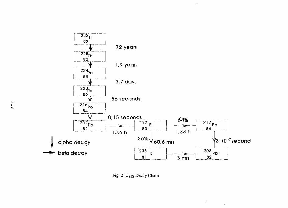
( -1CD
232",92
228Th90
88
72 years
1,9 years
3,7 days
86\p 56 seconds
84
"2l282
"Pb
0,15 seconds _^ [ 212
83Bi
X alpha decay
^** beta decay
10,6 h36%
F"208
64%
J 1,33 h
v 6 0 , 6 m n
TlI 3 mn
21284
Po
V3 10"7 second
20882
Pb
Fig. 2 U232 Decay Chain
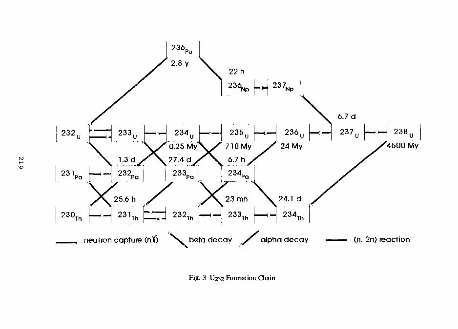
232,
231Pa
230Th
neutron capture (ntf)
236D
2.8 y
234
0.25 My
27.4 d
233,
4500 My
(n. 2n) reaction
Fig. 3 U232 Formation Chain
INTERMEDIATE FUEL ELEMENT STORAGE FACILITYAT REACTOR PR 3
Jens QvistReactor DR 3Erik Nonb0l
Nuclear Safety Research Dept.Riso National LaboratoryDK-4000 Roskilde, Denmark
ABSTRACT
In order to cope with delays in the back end of the fuelcycle, a dry vertical storage facility has been constructedat DR 3, a PLUTO type MTR reactor.
The capacity of the facility corresponds to ten years ofreactor operation.
The facility consist of four blocks with 12 storage holeseach. Each hole houses the equivalent of 9 fuel elements.
Each storage hole is ventilated in order to facilitatemonitoring of air humidity and contamination.
Special emphasis is placed on the criticality aspect due tothe compact design of the facility.
INTRODUCTION
The main research reactor at Rise National Laboratory is DR3, a PLUTO type MTR reactor (heavy water moderated and cooled).
Since start of the reactor in early 1961 the back end ofthe fuel cycle has been based upon reprocessing performed by anumber of contractors.
Over the years delays have been experienced for variousreasons in the back end of the fuel cycle. In 1991 it becameevident, that the then existing delay could be expected to be oflonger duration, and that storage capacity for spent fuel wouldbe a problem within few years. Consequently it was decide..1 toextend the intermediate storage capacity at the reactor. Thiscomprises two dry storage facilities and one pool. The latter isused for cutting, storage and transfer to the shipping cask.
220
Design Principles
From the onset, it was decided that the new facility shouldbe based upon the following principles:
a: Capacity of the facility should correspond to roughly 10years of reactor operation.
b: Location within the reactor facility area as this isroutinely surveyed by the operational staff.
c: Vertical storage which would minimize space demands andease transfer from the pool.
d: Storage of free cut fuel tubes only in order to reduce thesize of the facility.
e: No restrictions regarding burn-up i.e. fuel tubes withmaximum fissile content should be accommodated.
f: Long decay time before transfer as this would reduceproblems with regard to decay heat removal and minimizehealth physics risks during handling and storage.
g: Dry storage in order to eliminate corrosion problems andwater chemistry control.
h: Requirements for materials in contact with fuel tubes inorder to minimize corrosion problems.
i: Ventilation in order to assure drying of th-2 wet tubes fromthe pool and for monitoring humidity and activity.
Description of the Facility
The adopted principles resulted in a facility comprisingfour concrete blocks placed vertically under the floor of theactive handling bay.
The floor, designed for heavy loads, was cut between thebeams resulting in two rectangular holes each accommodating twoblocks. These were placed in steel lined holes drilled down intothe ground. This design allowed for prefabrication of the blocks,assuring well defined concrete quality and all the holes could befinished before the blocks were placed in the holes. The top faceof the blocks is a mild steel plate level with the floor and thetop 1.8 m between and around the blocks is filled with heavyconcrete while the space between a block and its liner is filledwith ordinary concrete.
221
Each block is an octagonal cylinder 0.88 m across flats and7.375 m high containing 12 storage holes as shown on Figure 1.The holes are placed in a tri3.ngular mesh with a distance of 226mm between the centerline of the holes. These are made up of mildsteel tubes, mild steel being chosen as the best material withregard to contact with concrete. The tubes are mutually supportedby spacers assuring correct geometry during construction as wellas during concrete pouring. The requirement regarding geometry isthat a tube center line should be within +/- 2 mm of correctgeometry. The. upper part of the holes is stepped and a mild steelplug 755 mm long constitutes shielding upwards.
The bottom of each hole is closed by a disc in the centerof which a small steel stud is placed.
Above the plug a space has been arranged for to accommodateseals. This space is closed by a disc with an 0-ring that sealsagainst the hole in the top plate.
Inside, the holes a stainless steel liner is suspended bymeans of a ring with a conical seat. The lower part of the lineris positioned radially with respect to the mild steel tube andthe liner tube ends 15 mm higher up than the bottom of the mildsteel tube.
Ventilation air is thus guided down through the liner tubeand up through the gap between the two tubes. An inlet manifoldis embedded in the concrete while outlet is via separate tubes inthe concrete. These tubes are lead to a common box on one of theflat sides of the block.
Each storage hole houses nine sets of fuel tubes. In orderto reduce the load on the tubes and minimize handling, threetubes are stacked on a common post and three posts are stackedone upon the other. The bottom of one post provides radialpositioning for the top of the post beneath. The post is made upby a central tube and a perforated bottom disc. The central tubeprovides radial positioning for the fuel tubes, besides it has acoupling devise for the transfer cask grab.
The post is made of stainless steel and as it, togetherwith the liner made of the same material, are the only componentsin contact with the fuel tubes, no corrosion problems are to beexpected.
Three posts can be accommodated in one storage hole,stacked one upon the other with the lower post resting on thestud in the bottom of the storage hole.
The above design results in a compact storage facility inwhich an equivalent of 432 fuel elements can be stored in fourblocks.
222
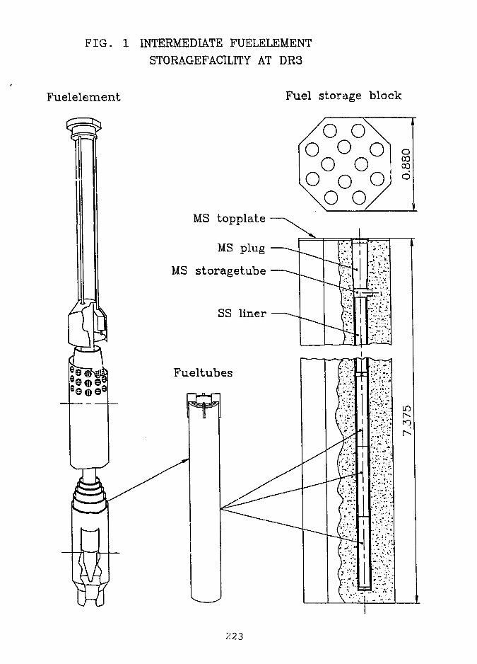
FIG. 1 INTERMEDIATE FUELELEMENT
STORAGEFACILJTY AT DR3
Fuelelement Fuel storage block
/
X)
1°\b os
oo ooP Q
\
o./
oCOCO
d
MS topplate
MS plug
MS storageiube
223
Ventilation and Monitoring
The ventilation system for the four blocks is connected tothe existing active handling bay ventilation system with itsHEPA, filter. • . : .,
The planned air humidity monitoring system is based upon asingle sensor in each of the four common outlet boxes, in case ofa steady increase in the reading the individual storage holeoutlet tubes will be monitored. If ground water in-le'ak is foundthe hole can be emptied and taken out of operation.
, Integrity of the cladding of the fuel tubes will bemonitored by means of similar procedure for air control.
Construction and status
Due-to th&pre-fabrication concept, the construction periodat the reactor facility area was very &hort - about,3 weeks. Nomajor problems were encountered during construction. ,The facilityis now awaiting testing mainly to verify that ventilation flowand humidity control meets specifications.
Control of shielding performance will take plaice as a partof tiie loading procedure,. when, the facility is operational.
Criticality calculations
Iri order to evaluate the possibility for criticaliiy in thefuel storage the multiplicati6n;;factbr- has been cei;lcuf.ated fordifferent I scenarios as to the content and distrikiitadn, of thefuel. ] I ' ••--;:/• "
• i i •,"" '• v r :
For•this purpose a two-dimensional code, CCCMO1, based oncollision'probability theory has been applied. This code has beenverified through several international benchmark problems and itis also tiised for cross section processing in connection with the3D-simuj.at.or of the DR 3 reactor2.
•' ' " i ' " i
Since the program CCCMO is two-dimensional the Calculationsare made under the assumption of infinite length intighe verticaldirection^ This assumption is also applied to the horizontalplane. Both assumptions make the calculation of the multi-plication? factor very conservative. The calculations areperformed' in 76 energy groups with the UKNDL cross sectionlibrary; from 1973 as basis.
If the calculations should have been made for the realgeometry Monte-Carlo methods should have been applied: But sincethe results of the calculations are very far from criticality we
224
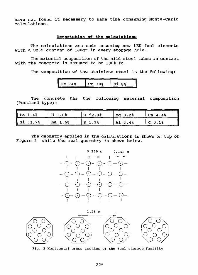
have not found it necessary to make time consuming Monte-Carlocalculations.
Description of the calculations
The calculations are made assuming new LEU fuel elementswith a U235 content of l80gr in every storage hole,
The material composition of the mild steel tubes in contactwith the concrete is assumed to be 100% Fe.
The composition of the stainless steel is the following:
Fe 74% Cr 18% Ni 8%
The concrete has the following material composition(Portland type):
Fe
1 si1.
33
4%
.7%
H
Na
1.0%
1.6%
O
K
52
1.
.9%
3%
Mg
Al
0.
3.
2%
4%
Ca
C
4.4%
0.1%
The geometry applied in the calculations is shown on top ofFigure 2 while the real geometry is shown below.
0.226 m 0.142 m
-0-G-O- O-0-0-i I ! i I I
-O-O-O-O-O- G-i I I I I i
-O-O-O-G-O-G-I i I I I f
-O-O-O-O-O-G-I i ! I I '
1.26 i
Fig. 2 Horizontal cross section of the fuel storage facility
225
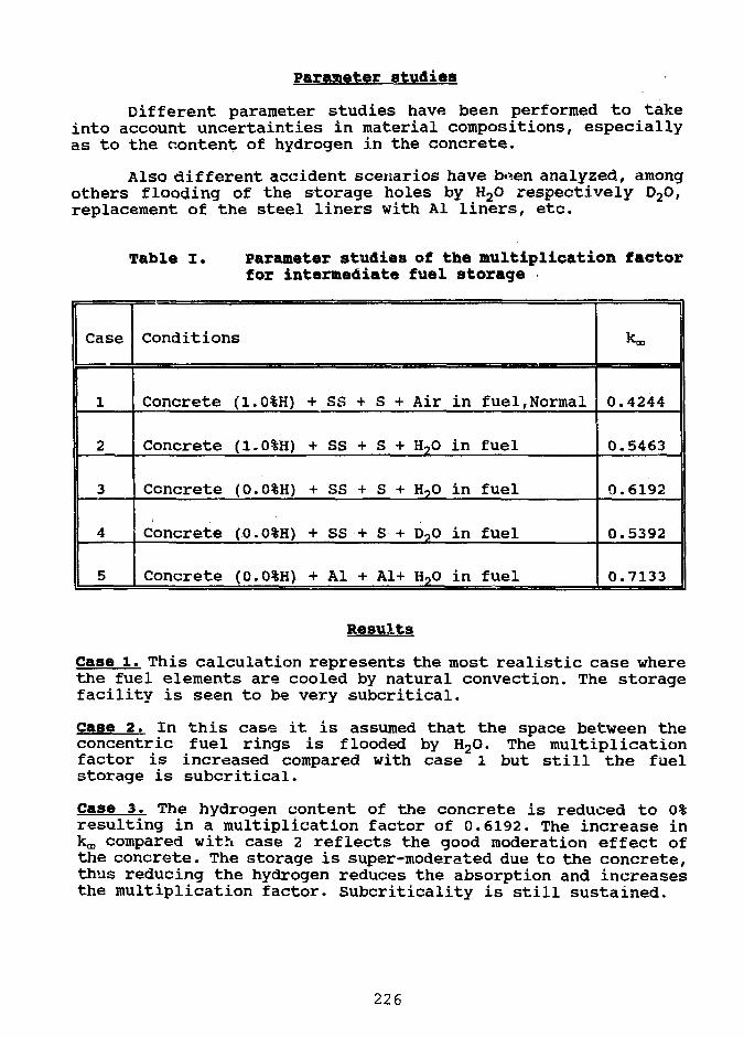
Parameter studies
Different parameter studies have been performed to takeinto account uncertainties in material compositions, especiallyas to the content of hydrogen in the concrete.
Also different accident scenarios have b*en analyzed, amongothers flooding of the storage holes by H2O respectively D20,replacement of the steel liners with Al liners, etc.
Table I. parameter studies of the multiplication factorfor intermediate fuel storage
Case
1
2
3
4
5
Conditions
Concrete (1.
Concrete (1.
Concrete (0.
Concrete (0.
Concrete (0.
0%H) -i
0%H) -
0%H) -
0%H) -
0%H) •
h SS H
1- SS H
f SS -
K SS -
f Al -
h S +
l- S +
1- S +
1- S +
I- A1+
Air
H?O
H?0
D?O
H,0
in
in
in
in
in
fuel,Normal
fuel
fuel
fuel
fuel
0.4244
0.5463
0.6192
0.5392
0.7133
Results
Case 1. This calculation represents the most realistic case wherethe fuel elements are cooled by natural convection. The storagefacility is seen to be very subcritical.
Case 2. In this case it is assumed that the space between theconcentric fuel rings is flooded by H2O. The multiplicationfactor is increased compared with case 1 but still the fuelstorage is subcritical.
Case 3. The hydrogen content of the concrete is reduced to 0%resulting in a multiplication factor of 0.6192. The increase inkm compared with case 2 reflects the good moderation effect ofthe concrete. The storage is super-moderated due to the concrete,thus reducing the hydrogen reduces the absorption and increasesthe multiplication factor. Subcriticality is still sustained.
226
Case 4. This scenario is like case 3 but with the space betweenthe fuel rings flooded by D20. The reduced multiplication factoris caused by the poor moderation effect of D2O compared with H20.
Case 5. Finally the stainless steel liners are substituted byaluminum liners. The multiplication factor is increased to 0.713 3but still the fuel storage facility is subcritical.
Conclusion
The calculations have shown that even with veryconservative assumptions, 180 gram LEU + infinite storage grid,the fuel storage is far from criticality.
If an accident should take place with the fuel storageflooded by water and taking uncertainties in materialcompositions into account, SS substituted with Al, the facilityis still kept subcritical.
In all the considered cases the distance to criticality isso far that even including the normal uncertainties in computermodelling the intermediate fuel storage facility at reactor DR 3should be well within the nuclear safety limits.
REFERENCES
1. C.F. Hojerup, "The Cluster Burnup Program CCCMO and aComparison of Results v/ith NPD Experiments", Riso-K-1898,1976.
2. E. Nonbol, "Development of a Model of the Danish ResearchReactor DR 3", Riso-M-2550, 1985.
227
S E S S I O N VII
September 30, 1992
SAFETY TESTS AND EVALUATIONS
Chairman:
(KURRI> Japan)
229
LONG TERM STORAGE/DIRECT DISPOSAL V REPROCESSING - A COMPARISON OF THECOSTS FOR RESEARCH AND TEST REACTOR OPERATORS
C. McColmAEA Fuel Services
ABSTRACT
Solutions to the back-end closure of the research reactor fuelcycle are being sought worldwide since the decision by US DOE tosuspend acceptance of spend fuel from abroad in 1988.
Reprocessing and subsequent credit/re-use of the recovereduranium has been the traditional method adopted as the solution.However, since operators have now been faced with the real costs ofreprocessing, subsequent waste treatment and disposal as opposed tothe incentive US DOE price of pre 1988, more cost beneficialalternatives are being sought.
One alternative being that of interim storage and possible finaldisposal in a national repository.
This short paper examines the global costs of the traditional andalternative solutions based on AEA's recent experience of interimstorage and extensive experience of reprocessing. The assignedmonetary values and assumptions used are meant for comparitorypurposes and reflect the most recent data available in the UK and thebasic assumption is that the sums involved will be largelyrepresentative of the industry worldwide.
MOX STORAGE FACILITY DESCRIPTION
A storage facility has been constructed at Dounreay to store 206unirradiated MOX fuelled sub-assemblies.
The store is approx 9 m long x 2.75 m wide x 4.1 high and isconstructed in reinforced concrete with vertical steel tubes providingsub-assembly location. Wall thickness is 0.4 m to provide shieldingfor the neutron emissions from plutonium and the y emissions fromPlutonium decay products, thus keeping surface dose rates to less than2.5 HSv/hr.
The facility is licensed by the Nuclear InstallationsInspectorate for ten years operation and is seismically qualified to apeak-ground acceleration of .2 g and a "cliff-edge" acceleration of0.2 5 g. It has forced cooling to cater for a peak load of 18 kw andis situated in a building with all radiological monitoring, physicalsecurity, cranage and support services installed.
231
Although the store was constructed for short-term (< 10 years),storage of unirradiated fuel, the fact that it is shielded andseismically qualified allows reasonable parallels to be drawn with therequirements for a shielded MTR store.
The principle differences will be the arrangements for loadingand unloading of irradiated fuel elements; the practice currently forthe MOX assemblies is flaskless transfer, clearly not possible forirradiated MTR elements. It is therefore envisaged that a rotatingshield roof for flask mating and indexing of the storage tubes will berequired at an additional cost of approximately £250K.
COST COMPARISON - REPROCESSING V INTERIM STORAGE/DISPOSAL
The following analysis determines the per element (see appendix 1for element description) costs to an operator for the management ofspent fuel arisings.
1. Reprocessing:
a. Reprocessing and waste conditioning
Using AEA Fuel Services published prices:
1 element @ 4 kg total metal x £4K/kg totalmetal
Reprocessing = £16K/element
b. Disposal to Repository
Using latest estimate for Intermediate Level Waste byUK Nirex Ltd:
20 kg total metal/m3, 4 kg total metal/element,£18K/m3 disposal
Disposal cost/element = 18K/20 x 4 = £3.6K/element
c. Totals
Total reprocessing/disposal = £16Kper fuel element + £3.6K
£19. 6K
2. Interim Storage/Disposal
a. Interim Storage
Using the costs estimated in appendix 2:
ie Capital Cost of Facility of £1MPer annum operating cost of £50K
232
It is assumed that element production rate is 3 0/year, the torecan hold 600 elements, earliest disposal is 20 years after irradiationan that reactor life is 20, 30, 40, and 50 years.
Using the above figures the Interim storage costs are therefore:
Reactor Life(yrs)
20
30
40
50
No of Elements(-)
600
900
1200
1500
Required StoreLife (YRS)*
40
50
60
70
Cost/Element(£K)
5.00
3.89
3.33
3.00
'Required store life is 20 years more than that of the reactor life as,due to the minimum cooling time for disposal, the store emptying timewill be 20 years.
b. Pre-treatment of Elements Prior to Disposal
Pre-treatment is required a) in order that the elements can bedismantled to distribute the lOOg fissile material between two wastepackages, thus keeping within the 100g/m3 or 50g/500 Q package limitsand b) to distribute the fissile material homogeneously within thepackages.
Maximum Cost: Very close to reprocessing as the process wouldessentially be one of distributing the fissile mass homogeneouslythroughout the; 500 5 drum ie dissolution, in-drum mixing with asubstrate and solidification. This is essentially reprocessingwithout the separation and removal of uranium. Licensing conditionsand capital investment identical to that of a reprocessing plant, ie£16K/element.
Minimum Cost: This would involve the mechanical breakdown of theelement, backfilling and sealing of the waste drums.
Estimated cost/element assuming that a shielded cell exists wouldbe approximately £5K/element. Licensing conditions would be similarto that of a PIE facility.
Range of costs.'. £5K to £16K/element.
c. Disposal to Repository
Using latest estimate by UK Nirex Ltd:-
lOOg fissile limit/m3, lOOg fissile/element, £18K/m3 disposal.
Disposal cost/element = £18K
233
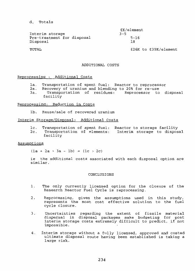
d. Totals
Interim storagePre-treatment for disposalDisposal
TOTAL
EK/element3-5
5-1618
£26K to £39K/element
ADDITIONAL COSTS
Reprocessing : Additional Costs
la. Transportation of spent fuel: Reactor to reprocessor2a. Recovery of uranium and blending to 20% for re-use3a. Transportation of residues: Reprocessor to disposal
facility
Reprocessing: Reduction in Costs
lb. Reuse/sale of recovered uranium
Interim Storage/Disposal: Additional Costs
lc. Transportation of spent fuel: Reactor to storage facility2c. Transportation of elements: Interim storage to disposal
facility
Assumptions
(la + 2a -<- 3a - lb) = (lc :- 2c)
ie the additional costs associated with each disposal option aresimilar.
CONCLUSIONS
1. The only currently licensed option for the closure of theResearch Reactor Fuel Cycle is reprocessing.
2. Reprocessing, given the assumptions used in this study,represents the most cost effective solution to the fuelcycle closure.
3. Uncertainties regarding the extent of fissile materialdispersal in disposal packages make budgeting for postinterim storage costs extremely difficult to predict, if notimpossible.
4. interim storage without a fully licensed, approved and costedultimate disposal route having been established is taking alarge risk.
234
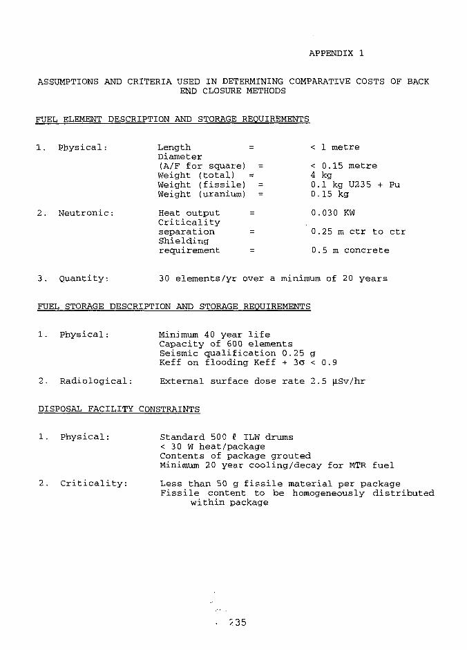
APPENDIX 1
ASSUMPTIONS AND CRITERIA USED IN DETERMINING COMPARATIVE COSTS OF BACK
END CLOSURE METHODS
FUEL ELEMENT DESCRIPTION AND STORAGE REQUIREMENTS
1. Physical: Length = < 1 metre
Diameter(A/F for square) = < 0.15 metreWeight (total) = 4 kgWeight (fissile) = 0.1 kg U23 5 + PuWeight (uranium) = 0.15 kg
2. Neutronic: Heat output = 0.030 KWCriticalityseparation = 0.25 m ctr to ctrShielding
requirement = 0.5m concrete
3. Quantity; 30 elements/yr over a minimum of 20 years
FUEL STORAGE DESCRIPTION AND STORAGE REQUIREMENTS
1. Physical: Minimum 40 year lifeCapacity of 600 elementsSeismic qualification 0.25 gKeff on flooding Keff + 3a < 0.9
2. Radiological: External surface dose rate 2.5 ^.Sv/hr
DISPOSAL FACILITY CONSTRAINTS
1. Physical: Standard 500 5 ILW drums
< 30 W heat/packageContents of package groutedMinimum 20 year cooling/decay for MTR fuel
2. Criticality: Less than 50 g fissile material per packageFissile content to be homogeneously distributed
within package
2 35
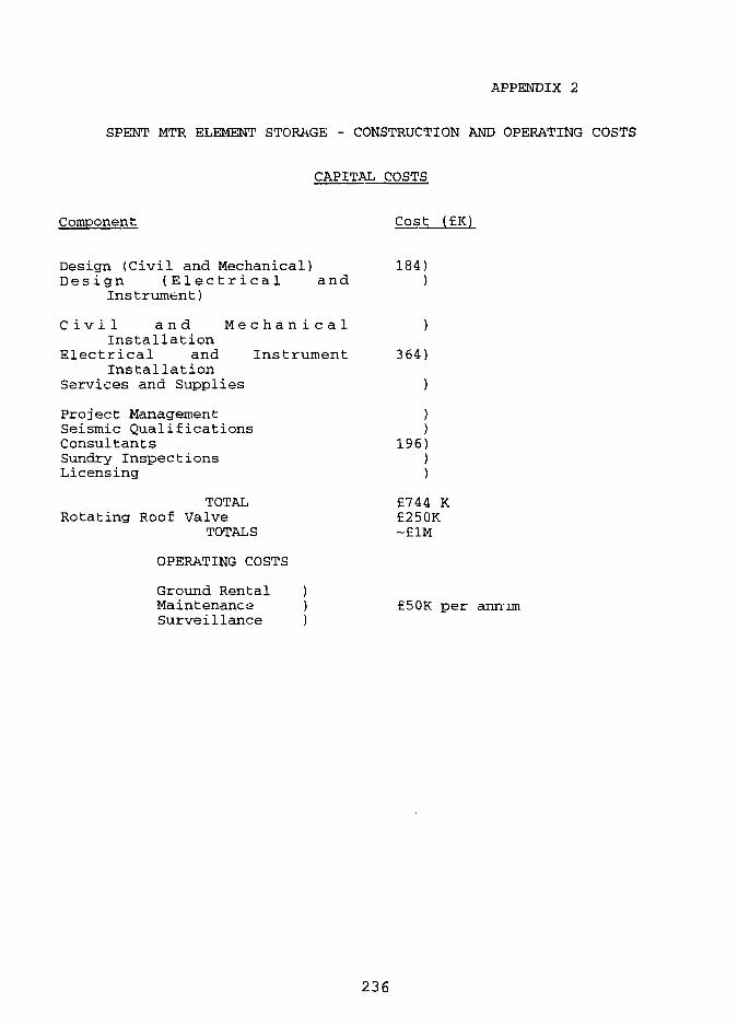
APPENDIX 2
SPENT MTR ELEMENT STORAGE - CONSTRUCTION AND OPERATING COSTS
CAPITAL COSTS
Component Cost (£K)
Design (Civil and Mechanical)Design (Electrical and
Instrument)
C i v i l a n d M e c h a n i c a lInstallation
Electrical and InstrumentInstallation
Services and Supplies
Project ManagementSeismic QualificationsConsultantsSundry InspectionsLicensing
TOTALRotating Roof Valve
TOTALS
OPERATING COSTS
Ground Rental )Maintenance )Surveillance )
184)
364)
196)
£744 K£250K-£1M
£5OK per annum
236
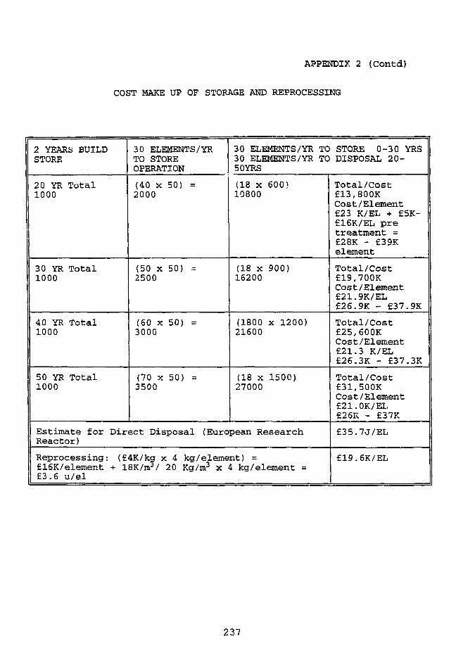
APPENDIX 2 (Contd)
COST MAKE UP OF STORAGE AND REPROCESSING
2 YEARS BUILDSTORE
20 YR Total1000
30 YR Total1000
40 YR Total1000
50 YR Total1000
30 ELEMENTS/YRTO STOREOPERATION
(40 x 50) =2000
(50 x 50) =2500
(60 x 50) =3000
(70 x 50) =3500
30 ELEMENTS/YR TO STORE 0-30 YRS30 ELEMENTS/YR TO DISPOSAL 20-50 YRS
(18 x 600}10800
(18 x 900)16200
(1800 x 1200)21600
(18 x 1500)27000
Estimate for Direct Disposal (European ResearchReactor)
Reprocessing: (£4K/kg x 4 kg/element) =£15K/element + 18K/m?/ 20 Kg/m3 x 4 kg/element =£3.6 u/el
Total/Cost£13,800KCost/Element£23 K/EL + £5K-£16K/EL pretreatment =£28K - £39Kelement
Total/Cost£19,700KCost/Element£21.9K/EL£26.9K - £37.9K
Total/Cost£25,600KCost/Element£21.3 K/EL£26.3K - £37.3K
Total/Cost£31,500KCost/Element£21.OK/EL£26K - £37K
£35.7J/EL
£19.6K/EL
237
A E A • =••••..• E u r o p e a n A Q , .... 5 Q 6 0 7 0 v 8 0Reprocessing Estimated Direct Years of Licensed Opera t i c^ *
o i , : - . . ' • D i s p o s a l . ; • • • • • • ] • • • • • • " - . .
• ' : .• • ' . " • • • - • • • • . - • ] . .'.- - ' ' • • • • • ' i ' - . . - • ' . • • : .
Reprocessing; Residue Disposal Cost
Direct Disposal Estimate " Operating Cost v
Waste Conditioninci CapitaS Cost
ANALYSES FOR CONVERSION OF THEGEORGIA TECH RESEARCH REACTOR
FROM HEU TO LEU FUEL
J.E. Matos, S.C. Mo, and W.L. WoodruffArgonne National Laboratory
Argonne, Illinois, USA
ABSTRACT
The 5 MW Georgia Tech Research Reactor (GTRR) is a heterogeneous, heavy watermoderated and cooled reactor, fueled with highly-enriched uranium aluminum alloy fuelplates. The GTRR is required to convert to low enrichment (LEU) fuel in accordance withUSNRC policy. Results of design and safety analyses performed by the RERTR Programat the Argonne National Laboratory for LEU conversion of the GTRR are summarized.Only those parameters which could change as a result of replacing the fuel are addressed.The performance of the reactor and all safety margins with LEU fuel are expected to beabout the same as those with the current HEU fuel.
INTRODUCTION
The results of design and safety analyses performed by the RERTR Program at the ArgonneNational Laboratory for conversion of the Georgia Tech Research Reactor from the use of HEUfuel to the use of LEU fuel are presented. The objectives of this work were to: (1) maintain orimprove upon the present reactor performance and margins of safety, (2) maintain as closely aspossible the technical specifications and operating procedures of the present HEU core, and (3)utilize a proven fuel assembly design that is economical to manufacture.
The GTRR core contains provisions for up to 19 fuel assemblies spaced 6 inches apart in atriangular array. The fuel is centrally located in a six-foot diameter aluminum vessel whichprovides a two-foot thick D2O reflector completely surrounding the core. The vessel issurrounded radially and beneath by an additional two-foot thick graphite reflector. The reactor iscontrolled by means of four cadmium shim-safety blades that swing downward through the corebetween adjacent rows of fuel assemblies and one cadmium regulating rod that moves vertically inthe radial D2O reflector. The reactor is equipped with 22 horizontal and 23 vertical experimentalfacilities for extracting neutron beams and performing irradiations. A shielded room (10 feet by12 feet inside) for biomedical research is located at the side of the reactor.
The reactor performance objectives and design constraints that were addressed in designingthe LEU fuel assembly are discussed in Ref. 1. The LEU fuel assembly has the same overalldesign as the present HEU fuel assembly, except that it contains 18 fueled plates with LEU U3Si2-Al fuel and two non-fueled plates instead of 16 fueled plates with HEU U-Al alloy fuel and 2 non-
239
fueled plates. Each HEU assembly contains 188 g 235U and each LEU assembly contains 225 g235U. The LEU core will use the same control system, heat removal system, and auxiliarysystems as the current HEU core.
Reactor ModelsA detailed Monte Carlo model of the reactor was constructed including all beam tubes,
experiment penetrations, the bio-medical facility, shim-safety blades, and regulating rod in order toobtain absolute excess reactivities and shutdown margins for comparison with limits specified inthe Technical Specifications. The diffusion theory model did not include the control absorbers orthe various experiment facilities. A simplified Monte Carlo model similar to the diffusion modelwas constructed to verify that the diffusion theory model was correct. Nuclear cross sections inseven energy groups were calculated using standard methods for use in the diffusion theorycalculations.
Critical ExperimentIn 1974, a critical experiment was built using 9 fresh HEU fuel assemblies. The core was
made critical at different shim-safety blade positions with the regulating rod nearly fully-withdrawn and nearly fully-inserted. The excess reactivities calculated for these criticalconfigurations using the detailed Monte Carlo model were -0.91 ± 0.20% Ak/k and -1.22 ± 0.22%Ak/k, respectively. The reactivity bias of about -1.0 ± 0.3% Ak/k in the calculations is attributed touncertainties in the nuclear cross sections and uncertainties in the reactor materials.
NEUTRONIC PARAMETERS
Excess ReactivityCalculated excess reactivities (including reactivity bias) for fresh HEU and LEU cores with 17
fuel assemblies are shown in Table 1. The Technical Specifications limit the excess reactivity to amaximum of 11.9% Ak/k. The LEU core is expected to satisfy this requirement.
Table 1. Excess Reactivities of HEU and LEU Cores with 17 Fresh Fuel Assemblies
Calculated Excess React.1, % Ak/k (±1CT)Fresh HEU Core Fresh LEU Core
Detailed Monte Carlo Model 11.7 ± 0.4 9.4 ± 0.4
Simplified Monte Carlo Model2 16.8 ± 0.4 14.3 ± 0.4Diffusion Theory Model2 16.6 14.6
1 The reactivity bias of -1.0 ± 0.3% Ak/k was added to calculated values. 2 Detailed Monte Carlomodel without experiment penetrations, shim-safety blades, and regulating rod.
The reactivity effect of replacing all air-filled experiment facilities in the detailed Monte Carlomodel with D2O or graphite was calculated to be 4.5 ± 0.3% Ak/k. Replacing the controlabsorbers in their fully-withdrawn position with D2O gave a worth consistent with zero. Thus, thesimplified Monte Carlo and diffusion theory models are consistent with the detailed Monte Carlomodel if the reactivity worth of the experiment facilities is accounted for.
240
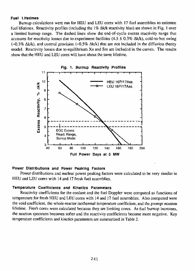
Fuel LifetimesBumup calculations were run for HEU and LEU cores with 17 fuel assemblies to estimate
fuel lifetimes. Reactivity profiles (including the 1% Ak/k reactivity bias) are shown in Fig. 1 overa limited burnup range. The dashed lines show the end-of-cycle excess reactivity range thataccounts for reactivity losses due to experiment facilities (4.5 ± 0.3% Ak/k), cold-to-hot swing(-0.3% Ak/k), and control provision (-0.5% Ak/k) that are not included in the diffusion theorymodel. Reactivity losses due to equilibrium Xe and Sm are included in the curves. The resultsshow that the HEU and LEU cores will have about the same lifetime.
Fig. 1. Burnup Reactivity Profiles
u(30>EC(0WO)oXUJ
11
10
9
8
7
6
5
4
HEU 16P/17ASS.LEU 18P/17Ass.
EOC ExcessReact. Range,Burnup Model
40 60 80 100 120 140 160
Full Power Days at 5 MW
180 200
Power Distributions and Power Peaking FactorsPower distributions and nuclear power peaking factors were calculated to be very similar in
HEU and LEU cores with 14 and 17 fresh fuel assemblies.
Temperature Coefficients and Kinetics ParametersReactivity coefficients for the coolant and the fuel Doppler were computed as functions of
temperature for fresh HEU and LEU cores with 14 and 17 fuel assemblies. Also computed werethe void coefficient, the whole-reactor isothermal temperature coefficient, and the prompt neutronlifetime. Fresh cores were calculated because they are limiting cores. As fuel burnup increases,the neutron spectrum becomes softer and the reactivity coefficients become more negative. Keytemperature coefficients and kinetics parameters are summarized in Table 2.
241
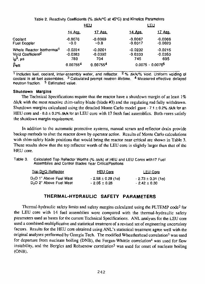
Table 2. Reactivity Coefficients (% Ak/k/°C at 45°C) and Kinetics Parameters
CoolantFuel Doppler
Whole Reactor Isothermal1
Void Coefficient2
•p3. ^s
Petf
14 Ass.
-0.0076-0.0
-0.0224-0.0383
780
0.007554
UEll17 Ass.
-0.0069-0.0
-0.0201-0.0392
704
0.007554
14 Ass.
-0.0067-0.0017
-0.0232-0.0333
745
0.0075
LEU17 Ass.
-0.0066-0.0020
-0.0215-0.0350
695
- 0.00765
1 Includes fuel, coolant, inter-assembly water, and reflector. 2 % Ak/k/% Void. Uniform voiding ofcoolant in all fuel assemblies. 3 Calculated prompt neutron lifetime. 4 Measured effective delayedneutron fraction. 5 Estimated value.
Shutdown MarginsThe Technical Specifications require that the reactor have a shutdown margin of at least 1%
Ak/k with the most reactive shim-safety blade (blade #3) and the regulating rod fully withdrawn.Shutdown margins calculated using the detailed Monte Carlo model gave - 7.1 ± 0.2% Ak/k for anHEU core and - 8.3 ± 0.2% Ak/k for an LEU core with 17 fresh fuel assemblies. Both cores satisfythe shutdown margin requirement.
In addition to the automatic protective systems, manual scram and reflector drain providebackup methods to shut the reactor down by operator action. Results of Monte Carlo calculationswith shim-safety blade positions that would bring the reactor near critical are shown in Table 3.These results show that the top reflector worth of the LEU core is slightly larger than that of theHEU core.
Table 3. Calculated Top Reflector Worths (% Ak/k) of HEU and LEU Cores with17 FuelAssemblies and Control Blades near CriticalPositions
Top D£O Reflector HEU Core LEU Core
D2O 1" Above Fuel Meat - 2.58 ± 0.29 (1a) - 2.73 ± 0.31 (1a)D2O 2" Above Fuel Meat - 2.05 ± 0.28 - 2.42 ± 0.30
THERMAL-HYDRAULIC SAFETY PARAMETERS
Thermal-hydraulic safety limits and safety margins calculated using the PLTEMP code2 forthe LEU core with 14 fuel assemblies were compared with the thermal-hydraulic safetyparameters used as bases for the current Technical Specifications. ANL analyses for the LEU coreused a combined multiplicative and statistical treatment of a revised set of engineering uncertaintyfactors. Results for the HEU cere obtained using ANL's statistical treatment agree well with theoriginal analyses performed by Georgia Tech. The modified Wheatherhead correlation3 was usedfor departure from nucleate boiling (DNB), the Forgan-Whittle correlation4 was used for flowinstability, and the Bergles and Rohsenow correlation5 was used for onset of nucleate boiling(ONB).
242
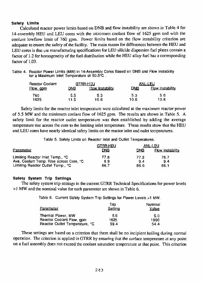
Safety LimitsCalculated reactor power limits based on DNB and flow instability are shown in Table 4 for
14-assembly HEU and LEU cores with the minimum coolant flow of 1625 gpm and with thecoolant lowflow limit of 760 gpm. Power limits based on the flow instability criterion areadequate to ensure the safety of the facility. The main reason for differences between the HEU andLEU cores is thai iae manufacturing specifications for LEU silicide dispersion fuel plates contain afactor of 1.2 for homogeneity of the fuel distribution while the HEU alloy fuel has a correspondingfactor of 1.03.
Table 4. Reactor Power Limits (MW) in 14-Assembly Cores Based on DNB and Flow Instabilityfor a Maximum Inlet Temperature of 50.5°C .
Reactor Coolant GTRR-H'EU ANL-LEUFlow, qpm DNB rlow Instability DNB Flow Instability
760 5.5 5.3 5.3 5.01625 11.5 10.6 10.8 10.6
Safety limits for the reactor inlet temperature were calculated at the maximum reactor powerof 5.5 MW and the minimum coolant flow of 1625 gpm. The results are shown in Table 5. Asafety limit for the reactor outlet temperature was then established by adding the averagetemperature rise across the core to the limiting inlet temperature. These results show that the HEUand LEU cores have nearly identical safety limits on the reactor inlet and oulet temperatures.
Table 5. Safety Limits on Reactor Inlet and Outlet Temperatures.
GTRR-HEU ANL-LELJParameter DNB DNB Flow InstabilityDNB
778
86
.8
.9
.7
Limiting Reactor Inlet Temp., °C 77.8 77.2 76.7Ave. Coolant Temp. Rise across Core, °C 8.9 9.4 9.4Limiting Reactor Outlet Temp., °C 86.7 86.6 86.1
Safety System Trip SettingsThe safety system trip settings in the current GTRR Technical Specifications for power levels
>1 MW and the nominal value for each parameter are shown in Table 6.
Table 6. Current Safety System Trip Settings for Power Levels >1 MW.
Trip NominalParameter Setting Value
Thermal Power, MW 5.5 5.0Reactor Coolant Flow, gpm 1625 1800Reactor Outlet Temperature, °C 59.4 54.4
These settings are based on a criterion that there shall be no incipient boiling during normaloperation. The criterion is applied in GTRR by ensuring that the surface temperature at any pointon a fuel assembly does not exceed the coolant saturation temperature at that point. This criterion
243
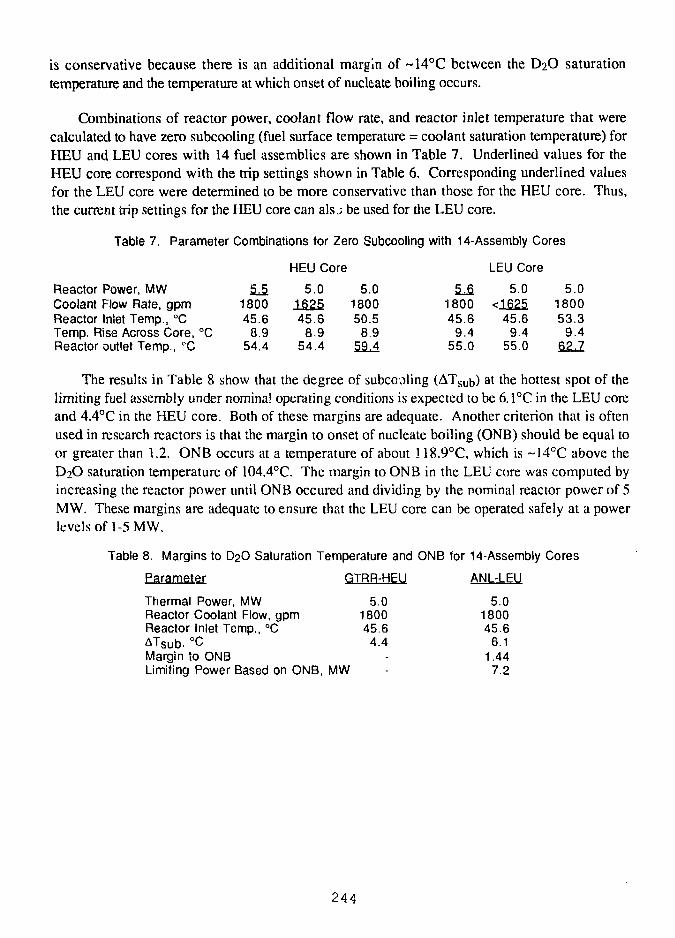
is conservative because there is an additional margin of ~14°C between the D2O saturationtemperature and the temperature at which onset of nucleate boiling occurs.
Combinations of reactor power, coolant flow rate, and reactor inlet temperature that werecalculated to have zero subcooling (fuel surface temperature = coolant saturation temperature) forHEU and LEU cores with 14 fuel assemblies are shown in Table 7. Underlined values for theHEU core correspond with the trip settings shown in Table 6. Corresponding underlined valuesfor the LEU core were determined to be more conservative than those for the HEU core. Thus,the current trip settings for the HEU core can als J be used for the LEU core.
Table 7. Parameter Combinations for Zero Subcooling with 14-Assembly Cores
HEU Core LEU Core
Reactor Power, MWCoolant Flow Rate, gpmReactor Inlet Temp., °CTemp. Rise Across Core, °CReactor outlet Temp., °C
5.5180045.6
8.954.4
5.0162545.6
8.954.4
5.0180050.5
8.959.4
5.6180045.6
9.455.0
5.0<1625
45.69.4
55.0
5.0180053.3
9.4QZJ.
The results in Table 8 show that the degree of subcooling (ATsub) at the hottest spot of thelimiting fuel assembly under nominal operating conditions is expected to be 6.1°C in the LEU coreand 4.4°C in the HEU core. Both of these margins are adequate. Another criterion that is oftenused in research reactors is that the margin to onset of nucleate boiling (ONB) should be equal toor greater than 1.2. ONB occurs at a temperature of about 118.9°C, which is ~14°C above theD2O saturation temperature of 104.4°C. The margin to ONB in the LEU core was computed byincreasing the reactor power until ONB occured and dividing by the nominal reactor power of 5MW. These margins are adequate to ensure that the LEU core can be operated safely at a powerlevels of 1-5 MW.
Table 8. Margins to D2O Saturation Temperature and ONB for 14-Assembly Cores
Parameter GTRR-HEU ANL-LEU
Thermal Power, MWReactor Coolant Flow, gpmReactor Inlet Temp., °CATsub, °CMargin to ONBLimiting Power Based on ONB, MW
5.0180045.6
4.4--
5.0180045.6
6.11.44
7.2
244
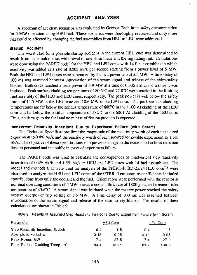
ACCIDENT ANALYSES
A spectrum of accident scenarios was evaluated by Georgia Tech in its safety documentationfor 5 MW operation using HEU fuel. These scenarios were thoroughly reviewed and only thosethat could be affected by changing the fuel assemblies from HEU to LEU were addressed.
Startup AccidentThe worst case for a possible startup accident in the current HEU core was determined to
result from the simultaneous withdrawal of one shim blade and the regulating rod. Calculationswere done using the PARET code6 for the HEU and LEU cores with 14 fuel assemblies in whichreactivity was added at a rate of 0.005 Ak/k per second starting from a power level of 5 MW.Both the HEU and LEU cores were scrammed by the overpower trip at 5.5 MW. A time delay of100 ms was assumed between introduction of the scram signal and release of the shim-safetyblades. Both cores reached a peak power of 5.9 MW at a time of 0.335 s after the transient wasinitiated. Peak surface cladding temperatures of 80.6°C and 77.8°C were reached in the limitingfuel assembly of the HEU and LEU cores, respectively. The peak power is well below the safetylimits of 11.5 MW in the HEU core and 10.6 MW in the LEU core. The peak surface claddingtemperatures are far below the solidus temperature of 660°C in the 1100 Al cladding of the HEUcore and far below the solidus temperature of 582°C in the 6061 Al cladding of the LEU core.Thus, no damage to the fuel and no release of fission products is expected.
Inadvertent Reactivity Insertions Due to Experiment Failure (with Scram)The Technical Specifications limit the magnitude of the reactivity worth of each unsecured
experiment to 0.4% Ak/k and the reactivity worth of each secured removable experiment to 1.5%Ak/k. The objective of these specifications is to prevent damage to the reactor and to limit radiationdose to personnel and the public in event of experiment failure.
The PARET code was used to calculate the consequences of inadvertent step reactivityinsertions of 0.4% Ak/k and 1.5% Ak/k in HEU and LEU cores with 14 fuel assemblies. Themodel and methods that were used for analysis of the SPERT-II BD-22/24 HEU core7-8 werealso used to analyze the HEU and LEU cores of the GTRR. Temperature coefficients includedcontributions from only the coolant and the fuel. Calculations were performed with the reactor atnominal operating conditions of 5 MW power, a coolant flow rate of 1800 gpm, and a reactor inlettemperature of 45.6°C. A scram signal was initiated when the reactor power reached the safetysystem overpower trip setting of 5.5 MW. A time delay of 100 ms was assumed betweenintroduction of the scram signal and release of the shim-safety blades. The results of thesecalculations are shown in Table 9.
Table 9. Results of Assumed Step Reactivity Insertions Due to Experiment Failure (with Scram)
Parameter HEU Core LEU Core
Step Reactivity Insertion, % Ak/k
Asymptotic Period, sPeak Power, MW
Peak Surface Cladding Temp., °C
245
0.4
0.187.4
84.4
1.50.0527.5
136.1
0.4
0.187.4
81.7
1.50.0527.2
130.6
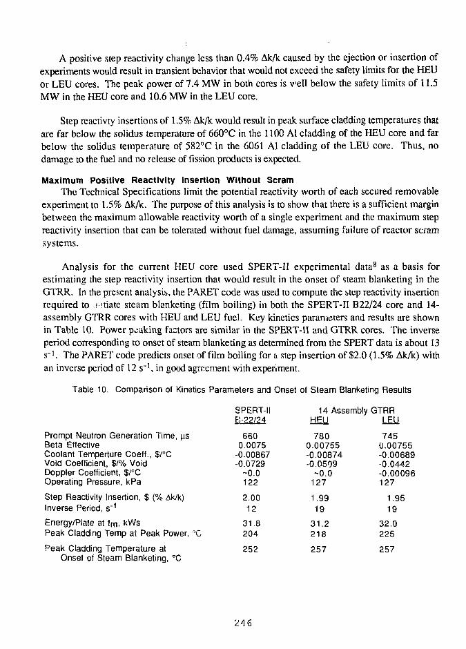
A positive step reactivity change less than 0.4% Ak/k caused by the ejection or insertion ofexperiments would result in transient behavior that would not exceed the safety limits for the HEUor LEU cores. The peak power of 7.4 MW in both cores is veil below the safely limits of 11.5MW in the HEU core and 10.6 MW in the LEU core.
Step reactivty insertions of 1.5% Ak/k would result in peak surface cladding temperatures thatare far below the solidus temperature of 660°C in the 1100 Al cladding of the HEU core and farbelow the solidus temperature of 582°C in the 6061 Al cladding of the LEU core. Thus, nodamage to the fuel and no release of fission products is expected.
Maximum Positive Reactivity Insertion Without ScramThe Technical Specifications limit the potential reactivity worth of each secured removable
experiment to 1.5% Ak/k. The purpose of this analysis is to show that there is a sufficient marginbetween the maximum allowable reactivity worth of a single experiment and the maximum stepreactivity insertion that can be tolerated without fuel damage, assuming failure of reactor scramsystems.
Analysis for the current HEU core used SPERT-II experimental data8 as a basis forestimating the step reactivity insertion that would result in the onset of steam blanketing in theGTRR. In the present analysis, the PARET code was used to compute the step reactivity insertionrequired to r itiate steam blanketing (film boiling) in both the SPERT-II B22/24 core and 14-assembly GTRR cores with HEU and LEU fuel. Key kinetics parameters and results are shownin Table 10. Power peaking factors are similar in the SPERT-II and GTRR cores. The inverseperiod corresponding to onset of steam blanketing as determined from the SPERT data is about 13s"1. The PARET code predicts onset of film boiling for a step insertion of $2.0 (1.5% Ak/k) withan inverse period of 12 s'1, in good agreement with experiment.
Table 10. Comparison of Kinetics Parameters and Onset of Steam Blanketing Results
Prompt Neutron Generation Time, usBeta EffectiveCoolant Temperture Coeff., $/°CVoid Coefficient, $/% VoidDoppler Coefficient, $/°COperating Pressure, kPa
Step Reactivity Insertion, $ (% Ak/k)Inverse Period, s"1
Energy/Plate at tm. kVVsPeak Cladding Temp at Peak Power, °C
Peak Cladding Temperature atOnset of Steam Blanketing, °C
SPERT-IIB-22/24
6600.0075
-0.00867-0.0729
-0.0122
2.0012
31.8204
14 AssemblyHEU
7800.00755-0.00874-0.0509
-0.0127
1.9919
31.2218
GTRRLEU
7450.00755-0.00689-0.0442-0.00096127
1.9519
32.0225
252 257 257
246
The same methodology was used to compute GTRR cores with 14 fuel assemblies. The stepinsertions needed to initiate film boiling (~$2.0) and the peak surface cladding temperatures (250-260°C) at the onset of steam blanketing are nearly the same. At the time of peak power, theenergy deposit \1 per p'ate is about the same in the SPERT and GTRR cores. The peak surfacecladding tempmture at the time of peak power is about 220°C in the GTRR cores and about204°C in the SPERT core.
The SPERT-II B22/24 tests8 indicate that even more extensive film boiling (or steamblanketing) does not result in temperatures that exceed the solidus temperature of the cladding.The most extreme case in the test series with a reactivity insertion of $2.95 (2.2% Ak/k) resulted ina peak surface cladding temperature of 337°C, a temperature far below the solidus temperature of582°C for 6061 Al cladding. The GTRR S AR also notes that the maximum temperature for largeinsertions is primarily limited by the energy deposited in the plate with very little effect from theboiling heat transfer.
Since the behavior of the SPERT-II B22/24 and GTRR 14-assembly cores is very similar, astep reactivity insertion greater than 2.2% Ak/k would be required to initiate melting of the GTRRLEU core. The margin of at least 0.7% Ak/k above the maximum allowed reactivity worth of1.5% Ak/k for a single experiment is sufficient to ensure that the facility is safe in the unlikelyevent that the maximum allowed reactivity were inserted in a step and the reactor scram systemfailed to function.
Design Basis AccidentThe Design Basis Accident for the HEU core in the GTRR safety documentation is the
melting and release of the fission products from one fuel assembly into the containmentatmosphere. This accident was assumed to occur during a fuel transfer operation in which anirradiated fuel assembly was being moved from the core to the fuel storage area using a shieldedtransfer cask. Fuel assemblies are not normally discharged from the reactor until at least 12 hoursafter reactor shutdown. This ensures that sufficient fission product decay heat has been removedfrom the assembly and that the surface temperature of the fuel plates will not reach 450°C whenthe assembly is moved into the cask.
In spite of administrative controls, it is conceivable that a fuel assembly could be withdrawnfrom the reactor prior to a 12 hour cooldown period. Some or all of the fuel plates within theassembly could then melt and release some of their fission products into the containmentatmosphere. In the current GTRR SAR, the source term for evaluating the radiologicalconsequences of this accident was obtained by assuming that an HEU fuel assembly withequilibrium burnup was removed from the core before the 12 hour cooldown period. All of theplates in the fuel assembly melt and the isotopes of iodine, krypton, and xenon were released to thecontainment. The limiting dose is the thyroid dose from the iodine isotopes.
Since the HEU and LEU cores operate at 5 MW, neutron flux levels and equilibriumconcentrations of iodine, xenon, and krypton will be about the same in the two cores. Fromburnup calculation results shown in Fig. 1, it was concluded that the lifetimes of the HEU and
247
LEU core will be about the same. As a result, concentrations of the other fission products in theLEU and HEU fuel assemblies will be very similar. The exception is that the LEU assembly willcontain larger concentrations of plutonium isotopes. Reference 9 contains a detailed analysiscomparing the radiological consequences of a hypothetical accident in a generic 10 MW reactorusing HEU and LEU fuels. This analysis concluded that the buildup of plutonium in dischargefuel assemblies with 235U burnup of over 50% does not significantly increase the radiologicalconsequences over those of HEU fuel. Because fission product concentrations in the GTRR HEUand LEU cores are expected to be comparable, the thyroid dose shown in the GTRR SAR forHEU fuel will be the limiting dose for both cores.
COOLING TIME REQUIREMENTS
The primary coolant pumps must be operated for 8 hours following operation at power levelsof more than 1 MW to preclude the possibility of fuel plate melting in the event of a loss-of-coolant accident following reactor shutdown. In addition, a minimum cooldown time of twelvehours is required before fuel assemblies are transferred out of the reactor. A limit of 450°C wasset in the Technical Specifications as the upper limit for a fuel plate temperature to preclude meltingof the plates.
The analysis method followed the superposition technique used in the GTRR safetydocumentation for the HEU core, with modification of the input parameters appropriate for theLEU fuel assembly design. The most important modification was that the maximum power perfuel plate in the LEU assembly was reduced by a factor of 16/18 since an HEU assembly contains16 fueled plates and an LEU assembly contains 18 fueled plates. A standard 3-week operatinghistory consisting of 4.3 days at full power of 5 MW and 2.7 days shutdown was used for 14assembly cores with HEU and LEU fuel.
The results for loss-of-coolant from the reactor vessel after eight hours of cooling gave amaximum plate temperature of 425°C in the HEU core and 400°C in the LEU core. Themaximum temperature occurred 45 minutes after loss-of-coolant in the HEU core and 50 minutesafter Ioss-of-coolant in the LEU core. Thus, the current Technical Specification requirements oncooling times are more conservative for the LEU core than for the HEU core.
FUEL HANDLING AND STORAGE
The objective of the Technical Specifications that apply to the handling and storage of fuelassemblies is to prevent inadvertent criticality outside of the reactor vessel and to preventoverheating of irradiated fuel assemblies.
Irradiated fuel assemblies are stored ,n aluminum racks fastened to the side walls of a lightwater pool. There is one rack along each of the two walls and each rack can accomodate up to 20
248
assemblies in a linear array. The center-to-center spacing of the assemblies is six inches and theseparation between assemblies is about three inches.
A systematic nuclear criticality assessment10 been done for infinite-by-infinite arrays of freshLEU fuel assemblies with 235U contents between 225 and 621 grams using the ORR fuel storagerack spacing specifications11 of 0.7 inch assembly separation and 6.8 inch row separation. Anassembly similar to the GTRR LEU assembly with a 235U content of 225 grams gave a keff of0.72, well below the maximum keff of 0.85 needed to ensure an adequate margin below criticalityfor storage of irradiated fuel assemblies. The GTRR storage configuration discussed above willhave keff less than 0.72.
Currently, no more than four unirradiated HEU fuel assemblies can be together in any oneroom outside the reactor, shipping container, or fuel storage racks. Calculations of HEU and LEUcores indicate that a grouping of four LEU assemblies will be less reactive than the sameconfiguration of HEU assemblies. Thus, the current specification will also hold for LEU fuel.
CONCLUSION
Conversion of the GTRR core from HEU to LEU fuel is feasible utilizing an LEU assemblycontaining 18 DOE standard silicide fuel plates (for university MTR-type reactors) as areplacement for the current HEU assembly with 16 fueled plates. Both HEU and LEU assembliescontain two unfueled outer plates to form an enclosed flow volume. The LEU assemblies wouldcontain 225 g 235U instead of 188 g 235U in the current HEU assemblies.
Calculations shown in Ref.l indicate that the epithermal flux at the bio-medical facility will beslightly larger in the LEU core. The lifetime of the LEU core is expected to be about the same asthat of the HEU core. All safety margins with the LEU fuel are very similar to those with thecurrent HEU fuel and are adequate to ensure the safety of the facility.
249
REFERENCES
1. R.A. Karam, J.E. Matos, S.C. Mo, and W.L. Woodruff, "Status Report on Conversion ofthe Georgia Tech Research Reactor to Low Enrichment Fuel," Proc. 1991 InternationalMeeting on Reduced Enrichment for Research and Test Reactors, Jakarta, Indonesia, 4-7November 1991 (to be published)
2. K. Mishima and T. Shibata, "Thermal-hydraulic Calculations for KUHFR with ReducedEnrichment Uranium Fuel," KURRI-TR-223 (1982), and K. Mishima, K. Kanda, and T.Shibata, "Thermal-hydraulic Analysis for Core Conversion to Use of Low-enrichedUranium Fuels in the KUR," KURRI-TR-258 (1984).
3. R. J. Weatherhead, "Nucleate Boiling Characteristics and the Critical Heat Flux Occurrencein Subcooled Axial-Flow Water Systems," ANL-6674, 1963.
4. R. H. Whittle and R. Forgan, "A Correlation for the Minima in the Pressure Drop VersusFlow-Rate Curves for Subcooled Water Flowing in Narrow Heated Channels," NuclearEngineering and Design, Vol. 6, (1967) pp. 89-99. "Guidebook on Research Reactor CoreConversion from the Use of Highly Enriched Uranium to the Use of Low EnrichedUranium Fuels", IAEA-TECDOC-233 (1980) pp. 99-106.
5. A.E. Bergles and W.M. Rohsenow, "The Determination of Forced-Convection Surface-Boiling Heat Transfers," Transactions of the ASME 86. (Series C - Journal of HeatTransfer), pp. 365-371 (August 1964).
6. C.F. Obenchain, "PARET - A Program for the Analysis of Reactor Transients," IDO-17282, Idaho National Engineering Laboratory (1969).
7. W. L. Woodruff, "Additional Capabilities and Benchmarking with the SPERT Transients forHeavy Water Applications of the PARET Code," Proc. Xllth International Meeting onReduced Enrichment for Research and Test Reactors, Berlin, 10.-14. September 1989.,Konferenzen des Forschungs-zentrums Jiilich(1991).
8. J. d. Grund, "Self-Limiting Excursion Tests of a Highly Enriched Plate-Type D2O-Moderaied Reactor, Part I. Initial Test Series", USAEC Report IDO-16891, PhillipsPetroleum Co., July 12, 1963.
9. W.L. Woodruff, D.K. Warinner, and J.E. Matos, "A Radiological Consequence Analysiswith HEU and LEU Fuels," Proc. 1984 International Meeting on Reduced Enrichment forResearch and Test Reactors, Argonne National Laboratory, Argonne, IL, October 15-18,1984, ANL/RERTR/TM-6, CONF-8410173, pp. 472-490 (July 1985).
10. R.B. Pond and J.E. Matos, "Nuclear Criticality Assessment of LEU and HEU Fuel ElementStorage," Proc. 1983 International Meeting on Reduced Enrichment for Research and TestReactors, Japan Atomic Energy Research Institute, Tokai, Japan, October 24-27, 1983,JAERI-M 84-073, pp. 416-425 (May 1984).
11. J.T. Thomas, "Nuclear Criticality Assessment of Oak Ridge Research Reactor Fuel ElementStorage," ORNL/CSD/TM-58, Oak Ridge National Laboratory (1978).
250
SAFETY ANALYSIS OF THE JMTR WITH LEU FUEL
Yoshihiro Komori, Fumio Sakurai, Etsuo Ishitsuka, Takeshi Sato,Minoru Saito and Yoshiaki Futamura
Japan Atomic Energy Research InstituteOarai Research Establishment
Oarai-machi, Ibaraki-ken, Japan
ABSTRACT
The license on the use of the LEU s i l ic ide fuel for the JMTR(Japan Materials Testing Reactor) was issued in March of 1992, andthe core conversion wil l be carried out in 1993. The safetyanalysis for the JMTR LEU core was performed in order to examinevalidity of the safety design principles. Safety cri teria for theabnormal conditions were also reviewed. The result suggests thatemergency cooling system and safety protection system need to beupgraded for the primary coolant piping failure. Other postulatedabnormal conditions were verified to be safely handled with thepresent safety system.
INTRODUCTION
The JMTR is a 50MW tank type reactor, moderated and cooled by light water.The primary cooling system is pressurized at about 14 kg/cm2G. The reactorcore consists of 22 standard fuel elements, 5 control rods with fuel followers,beryllium and aluminium reflectors with irradiation holes. The operatingpattern of the JMTR with the present MEU core follows 26-day operating periodincluding 2-day middle shutdown for refueling. Thermohydraulic data of theJMTR are shown in Table 1.
The core conversion from MEU fuel to LEU fuel will be scheduled to bemade in 1993. The U3Si2 fuel with U.8 g/cm3 of uranium density was selectedas the LEU fuel in order to eliminate the middle shutdown for refueling.Burnable absorbers of aluminum sheathed Cd wires are placed in each side platetc adjust the excess reactivity at the beginning of an operating cycle.
For the core conversion, the safety analysis of the JMTR was entirelyreviewed and revised based on the l a t e s t knowledge such as new DNBcorrelation[1 ] . Design Basis Events (DBEs) of the reactor were reconsidered.Selected DBEs were classified into abnormal transients during operation andaccidents, and responses of the reactor to these DBEs were analyzed.
251
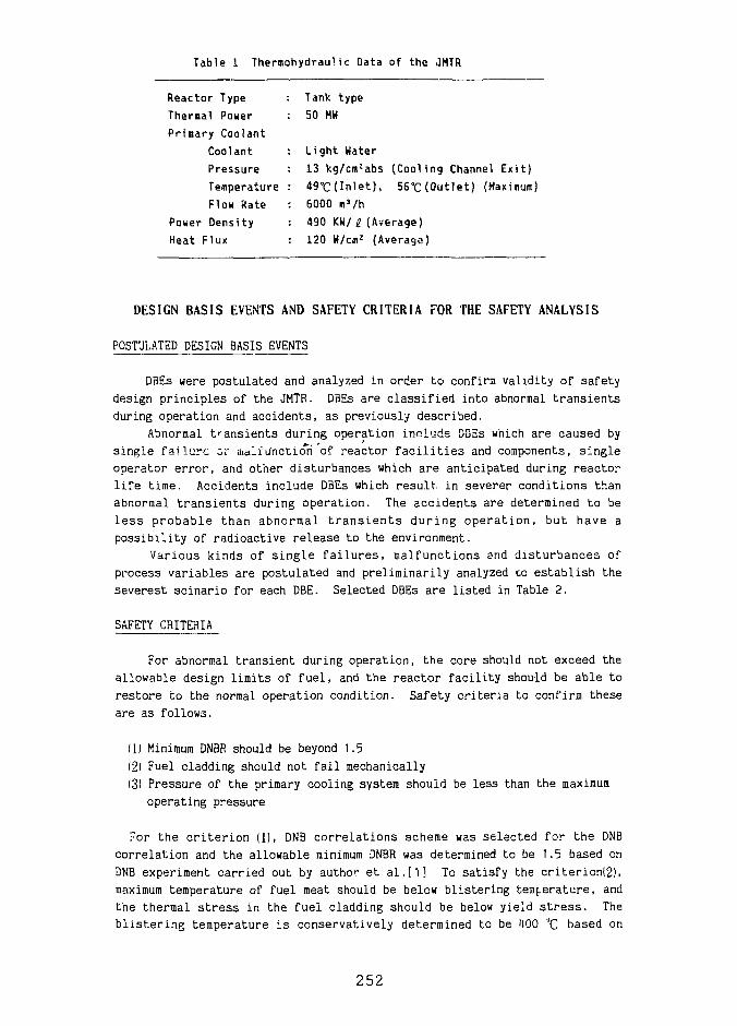
Table 1 Thermohydraui. ic nata of the ,1MTR
Reactor TypeThermal PowerPrimary Coolant
CoolantPressureTemperatureFlow Rate
Power DensityHeat Flux
Tank type50 MW
Light Water13 kg/cmJabs (Cooling Channel Exit)49°C(Inlet), 56"C (Outlet) (Maximum)6000 mVh
: 490 KW/ I (Average)• 120 W/cmz (Average)
DESIGN BASIS EVENTS AND SAFETY CRITERIA FOR THE SAFETY ANALYSIS
POSTULATED DESIGN BASIS EVENTS
DBEs were postulated and analyzed in order to confirm validity of safetydesign principles of the JMTR. DBEs are classified into abnormal transientsduring operation and accidents, as previously described.
Abnormal transients during operation include DBEs which are caused bysingle failure or malfunction of reactor facilities and components, singleoperator error, and other disturbances which are anticipated during reactorlife time. Accidents include DBEs which result, in severer conditions thanabnormal transients during operation. The accidents are determined to beless probable than abnormal transients during operation, but have apossibility of radioactive release to the environment.
Various kinds of single failures, malfunctions and disturbances ofprocess variables are postulated and preliminarily analyzed co establish theseverest scinario for each DBE. Selected DBEs are listed in Table 2.
SAFETY CRITERIA
For abnormal transient during operation, the core should not exceed theallowable design limits of fuel, and the reactor facility should be able torestore to the normal operation condition. Safety criteria to confirm theseare as follows.
(1) Minimum DNBR should be beyond 1.5(2) Fuel cladding should not fail mechanically
(3) Pressure of the primary cooling system should be less than the maximumoperating pressure
For the criterion (1), DNB correlations scheme was selected for the DNBcorrelation and the allowable minimum DNBR was determined to be 1.5 based onDNB experiment carried out by author et al.[l] To satisfy the criterion(2),maximum temperature of fuel meat should be below blistering temperature, andthe thermal stress in the fuel cladding should be below yield stress. Theblistering temperature is conservatively determined to be HOO °C based on
252
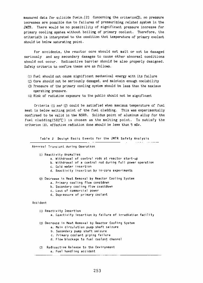
measured data for silicide fuels.[2] Concerning the criterion(3), no pressureincreases are possible due to failures of pressurizing related system in theJMTR. There would be no possibility of significant pressure increase forprimary cooling system without boiling of primary coolant. Therefore, thecriteria(3) is interpreted to the condition that temperature of primary coolantshould be below saturating point.
For accidents, the reactor core should not melt or not be damagedseriously and any secondary damages to cause other abnormal conditionsshould not occur. Radioactive barrier should be also properly designed.Safety criteria to confirm these are as follows.
(1) Fuel should not cause significant mechanical energy with its failure(2) Core should not be seriously damaged, and maintain enough coolability(3) Pressure of the primary cooling system should be less than the maximum
operating pressure.(4) Risk of radiation exposure to the public should not be significant
Criteria (1) and (2) could be satisfied when maximum temperature of fuelmeat is below melting point of the fuel cladding. This was experimentallyconfirmed to be valid in the NSRR. Solidus point of aluminum alloy for thefuel cladding(582°C) is chosen as the melting point. To satisfy thecriterion (4), effective radiation dose should be less than 5 mSv.
Table 2 Design Basis Events for the JMTR Safety Analysis
Abnormal Transient during Operation
(1) Reactivity Anomaliesa. Withdrawal of control rods at reactor start-upb. Withdrawal of a control rod during full power operationc. Cold water insertiond. Reactivity insertion by in-core experiments
(2) Decrease in Heat Removal by Reactor Cooling Systema. Primary cooling flow coastdownb. Secondary cooling flow coastdownc. Loss of commercial powerd. Depressure of primary coolant
Accident
(II Reactivity Insertiona. Reactivity insertion by failure of irradiation facility
(21 Decrease in Heat Removal by Reactor Cooling Systema. Main circulation pump shaft seizureb. Secondary pump shaft seizurec. Primary coolant piping failured. Flow blockage to fuel coolant channel
(3) Radioactive Release to the Environmenta. Fuel handling accident
253
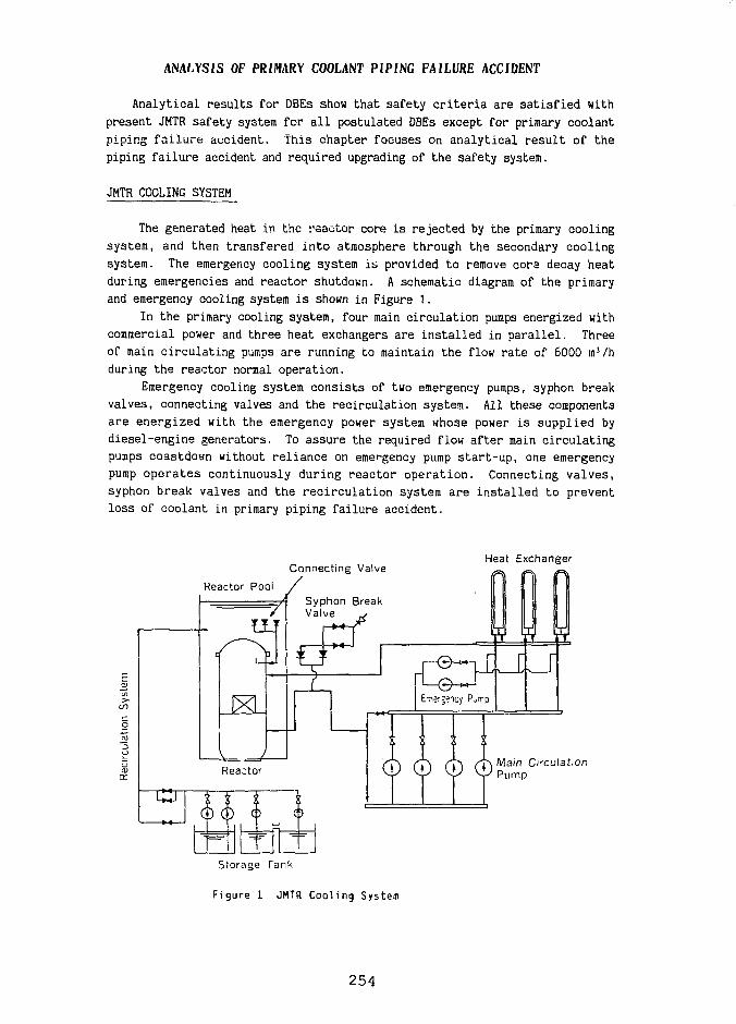
ANALYSIS OF PRIMARY COOLANT PIPING FAILURE ACCIDENT
Analytical results for DBEs show that safety cr i ter ia are satisfied withpresent JMTR safety system for a l l postulated DBEs except for primary coolantpiping fai lure accident. This chapter focuses on analytical result of thepiping failure accident and required upgrading of the safety system.
JMTR COOLING SYSTEM
The generated heat in the rsae tor core i s rejected by the primary coolingsystem, and then t ransfered i n t o atmosphere through the secondary cool ingsystem. The emergency cooling system it, provided to remove cora decay heatduring emergencies and reac tor shutdown. A schematic diagram of the primaryand emergency cooling system i s shown in Figure 1.
In the primary cooling system, four main c i rcula t ion pumps energized withcommercial power and three heat exchangers are i n s t a l l e d in p a r a l l e l . Threeof main c i r cu l a t i ng pumps are running to maintain the flow ra t e of 6000 mVhduring the reactor normal operat ion.
Emergency cooling system cons i s t s of two emergency pumps, syphon breakvalves, connecting valves and the rec i rcula t ion system. All these componentsa re energ ized with the emergency power system whose power i s supp l ied bydiesel-engine generators. To assure the required flow af ter main c i rcu la t ingpumps coastdown without r e l i a n c e on emergency pump s t a r t - u p , one emergencypump o p e r a t e s continuously dur ing r eac to r o p e r a t i o n . Connecting v a l v e s ,syphon break valves and the r e c i r c u l a t i o n system are i n s t a l l e d to preventloss of coolant in primary piping fa i lure accident .
Connecting Valve
Reactor Pool ySyphon BreakValve
Heat Exchanger
Main Circulation
Storage Tank
Figure 1 JMTR Coaling System
254
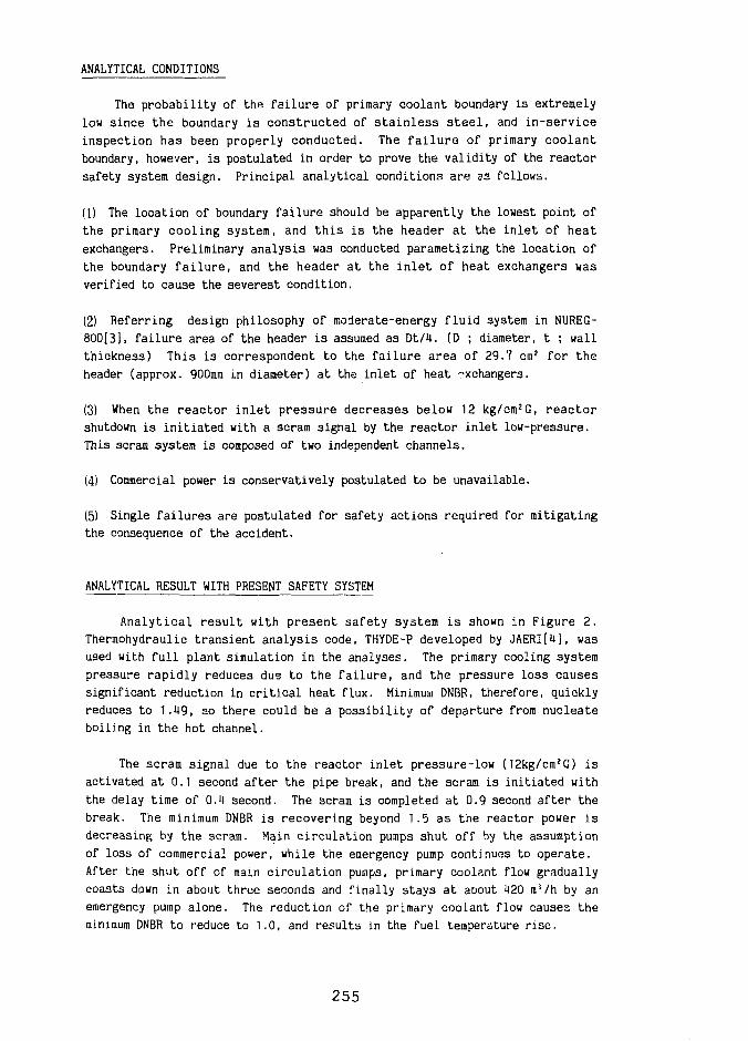
ANALYTICAL CONDITIONS
The probability of the failure of primary coolant boundary is extremelylow since the boundary is constructed of stainless steel, and in-serviceinspection has been properly conducted. The failure of primary coolantboundary, however, is postulated in order to prove the validity of the reactorsafety system design. Principal analytical conditions are as follows.
(1) The location of boundary failure should be apparently the lowest point ofthe primary cooling system, and this is the header at the inlet of heatexchangers. Preliminary analysis was conducted parametizing the location ofthe boundary failure, and the header at the inlet of heat exchangers wasverified to cause the severest condition.
(2) Referring design philosophy of moderate-energy fluid system in NUREG-8OO[3]. failure area of the header is assumed as Dt/U. (D ; diameter, t ; wallthickness) This is correspondent to the failure area of 29.7 cm2 for theheader (approx. 900mm in diameter) at the inlet of heat exchangers.
(3) When the reactor inlet pressure decreases below 12 kg/cm 2G, reactorshutdown is initiated with a scram signal by the reactor inlet low-pressure.This scram system is composed of two independent channels.
(4) Commercial power is conservatively postulated to be unavailable.
(5) Single failures are postulated for safety actions required for mitigatingthe consequence of the accident.
ANALYTICAL RESULT WITH PRESENT SAFETY SYSTEM
Analytical result with present safety system is shown in Figure 2.Thermohydraulic transient analysis code, THYDE-P developed by JAERI[U], wasused with full plant simulation in the analyses. The primary cooling systempressure rapidly reduces due to the failure, and the pressure loss causessignificant reduction in critical heat flux. Minimum DNBR, therefore, quicklyreduces to 1.H9, so there could be a possibility of departure from nucleateboiling in the hot channel.
The scram signal due to the reactor inlet pressure-low (12kg/cm?G) isactivated at 0.1 second after the pipe break, and the scram is initiated withthe delay time of 0.1 second. The scram is completed at 0.9 second after thebreak. The minimum DNBR is recovering beyond 1.5 as the reactor power isdecreasing by the scram. Main circulation pumps shut off by the assumptionof loss of commercial power, while the emergency pump continues to operate.After the shut off of main circulation pumps, primary coolant flow graduallycoasts down in about three seconds and finally stays at aoout U20 m!/h by anemergency pump alone. The reduction of the primary coolant flow causes theminimum DNBR to reduce to 1.0, and results in the fuel temperature rise.
255
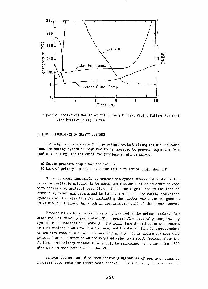
260
220 -
H 180CD
| 1 4 Cctia.
I 100
60
70
I \
r 1 Max. Fuel
^Coolant
i i i
V\Temp.
Outlet
/DNBR /
\ y ^
Temp.
i t i i
- 5
-4
- 3CO
- 2
4 6Time (s)
10
Figure 2 Analytical Result of the Primary Coolant Piping Failure Accidentwith Present Safety System
REQUIRED UPGRADINGS OF SAFETY SYSTEMS
Thermohydraulic analysis for the primary coolant piping failure indicatesthat the safety system is required to be upgraded to prevent departure fromnucleate boiling, and following two problems should be solved.
a) Sudden pressure drop after the failure
b) Lack of primary coolant flow after main circulating pumps shut off
Since it seems impossible to prevent the system pressure drop due to the
break, a realistic solution is to scram the reactor earlier in order to cope
with decreasing critical heat flux. The scram signal due to the loss of
commercial power was determined to be newly added to the safety protection
system, ?.nd its delay time for initiating the reactor scram was designed to
be within 200 miliseconds, which is approximately half of the present scram.
Problem b) could be solved simply by increasing the primary coolant flow
after main circulating pumps shutoff. Required flow rate of primary cooling
system is illustrated in Figure 3. The solid line(A) indicates the present
primary coolant flow after the failure, and the dashed line is correspondent
to the flow rate to maintain minimum DNBR at 1.5. It is apparently seen that
present flow rate drops below the required value from about 7seconds after the
failure, and primary coolant flow should be maintained at no less than 1300
a'/h to eliminate potential of the DNB.
Various options were discussed including upgradings of emergency pumps toincrease flow rate for decay heat removal. This option, however, would
256
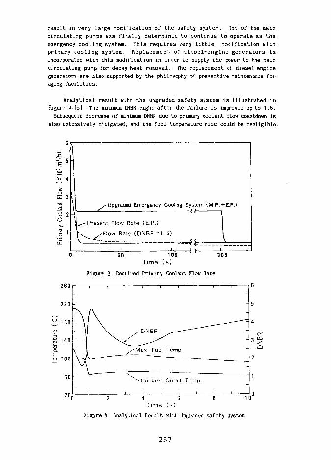
result in very large modification of the safety system. One of the maincirculat ing pumps was finally determined to continue to operate as theemergency cooling system. This requires very l i t t l e modification withprimary cooling system. Replacement of d lese l -engine generators i sincorporated with this modification in order to supply the power to the maincirculating pump for decay heat removal. The replacement of diesel-enginegenerators are also supported by the philosophy of preventive maintenance foraging fac i l i t i es .
Analytical result with the upgraded safety system is i l lus t ra ted inFigure U.[5] The minimum DNBR right after the failure i s improved up to 1.6.
Subsequent decrease of minimum DNBR due to primary coolant flow coastdown isalso extensively mitigated, and the fuel temperature r ise could be negligible.
s-Upgraded Emergency Cooling System (M.P.+ E.P.)
Present Flow Rate (E.P.)
/ F l o w Rate (DNBR = 1.5)
50 100 300Time (s)
Figure 3 Required Primary Coolant Flow Rate
260
220
Coolant Outlet Temp.
20D 2 4 6 8 1T i m e ( s )
Figyre 4 Analytical Result with Upgraded safety System
257
CONCLUDING REMARKS
Safety analysis of the JMTR LEU core on the latest knowledges shows thatsafety c r i t e r i a are satisfied with the present JMTR safety system for a l lpostulated DBEs except for primary coolant piping failure accident. One ofthe main c i rcula t ing pump i s going to be modified to continue to operateafter the primary coolant piping fa i lu re accident in order to maintainrequired flow r a t e . The safety protection system and the emergency powersystem is determined to be upgraded.
REFERENCES
[1] Y.Koraori, e t a l . : Experimental Study on DMB Heat Flux Correlations forthe JMTR Safety Analysis, 13th RERTR International Meeting (1990)
[2] U.S.Nuclear Regulatory Commission : Safety Evaluation Report Related to theEvaluation of Low-Enriched Uranium Silicida-Aluminum Dispersion Fuel for Usein Non-Power Reactors, NUREG-1313 (1988)
[3] U.S.Nuclear Regulatory Commission : Standard Review Plan for the Review ofSafety Analysis Reports for Nuclear Power Plants, NUREG-800 (1981)
[U] Y.Asahi, e t a l . : THYDE-W; RCS(Reactor Coolant System) Analysis Code,JAERI-M-90-172 (1990)
[5] Etsuo Ish i tuka , et a l . : Safety Analysis of JMTR LEU Fuel Cores (2)-Thermohydraulic Analysis- (in Japanese), JAERI-M-92-096 (1992)
258
DOSE ANALYSIS IN SAFETY AND SITE EVALUATIONFOR TOE JWIR CORE CONVERSION TO LEU FUEL
Noboru Tsuchida, Tadao Shiraishi, Yutaka Takahashi,Seij i Inada, Kyoshiro Kitano, Minoru Saito
and Yoshlaki Futamura
Japan Atomic Energy Research Insti tuteOarai Research Establishment
Oarai-machi, Ibaraki-ken, Japan
ABSTRACT
Dose analyses in the safety evaluation and the s i teevaluation were performed for the Japan Materials TestingReactor(JMTR) core conversion from Medium EnrichmentUranium(MEU) fuel to Low Enrichment Uranium(LEU) fuel. In thesafety evaluation, the effective dose equivalents for the publicsurrounding the s i te were estimated in the design basisaccidents with release of radioactive fission products to theenvironment. In the site evaluation, maximum exposure doses tothe public were estimated in major accident and hypotheticalaccident. I t was confirmed that risk of radiation exposure ofthe public is negligible and the siting is appropriate for theLEU core as for the present MEU core.
INIHODUCTION
The safety and s i t e evaluation was executed for the JMTR core conversion from MEUfuel (UAlx-Al) to LEU fuel (U,Si2-Al).
The exposure doses to the pub l i c surrounding the s i t e were evaluated for thepostulated accidents . Flow blockage to a coolant channel and fuel handling accident werese lec ted as the dose evaluating event among the design Dasis accide.nt3 of the JMTR,because these accidents were possible to re lease radioactive to the environment.
In the flow blockage to a coolant channel, the influence of the radiat ion to thepublic i s evaluated on the assumption tha t two fuel p la tes formed a coolant channel aredamaged due to cooling shortage af ter operating for 125 days a t 50 MW. While in the fuelhandling accident , one fuel plate i s damaged due to drop a fuel element in handling totake out from the reactor core after a day since the reactor shutdown.
In the s i t e evaluation, the flow blockage to a coolant channel i s selected for themajor accident and the hypothetical accident which are defined as the s i t ing basis events' ,because i t has the possibi l i ty of spreading radioactive release. The major accident i s theupper limit of accident which i s considered to occur from the engineering standpoint. Thehypothetical accident i s the postulated accident with re lease of radioactive mater ia lsbeyond the major acc ident . I t i s assumed tha t 5% of f i ss ion products inventory in the
reactor would be released from the fuel for the major accident, and 100} would be releasedfor the hypothetical accident.
OF DOSE ASSESSMENTFor the evaluation of the off-site radiation exposure in the accidents, the following
four exposure pathways are considered:
1. Internal exposure by inhalation of the radioactive that is released to theatmosphere.
2. External gamma-ray exposure from the radioactive cloud that is released to theatmosphere.
3. Direct external gamma-ray exposure from fission products that are released into thereactor building.
4. External skyshine gamma-ray exposure from fission products that are released intothe reactor building.
Fig. 1 shows the flowchart of dose analyses in the accidents.In the design basis accidents, the radiation exposures are calculated in effective
dose equivalents, and total effective dose equivalent is obtained by summing them.In the siting basis events, the maximum exposure doses to the thyroid and the whole
body are calculated. For the hypothetical accident, a collective dose is also calculated.
Noble gases and iodine ot fission products, respectively, mainly contribute to thedoses. For this analysis, the release fraction of iodine from damaged silicide fuel wasadopted to be 60%. The validity of the value was confirmed by a experiment2 in theDepartment of JMTR Project.
FLOW BLOCKAGE TO COOLANT CHANNELIn the flow blockage to coolant channel, the amount of fission products released to
the atmosphere is evaluated by using the release paths model, as shown in Fig.2. Therelease paths and parameters of fission products in the accident are shown in Fig.3.
In the accident, fission products released into the coolant are transferred to thedegas tank and the reactor building through the primary cooling system. For 5 min afterthe accident initiation, the fission products in the degas tank are discharged i . a thestack to the atmosphere via the irradiation experiment facilities ventilation system, andthe fission products in the reactor building are discharged via the normal ventilationsystem.
Within 5 min from the accident initiation, fission products in the primary coolantare detected by the fuel failure detection system. When the fission products are detected,the reactor is shut down, at the same time, isolation valves (a), (b), (c) and (d) asshown in Fig.2 are closed and the normal and irradiation experiment f a c i l i t i e sventilation systems are stopped to prevent release of fission products. The emergencyventilation system is always operating under normal and accident conditions usingemergency electric source.
It is assumed in the safety analysis that the leakage of the fission products fromthe primary cooling system to the reactor building continues for long period after 5 minfrom the accident ini t iat ion. Fission products leaked to the reactor building aredischarged from the stack to the atmosphere via the emergency ventilation system. In thisanalysis, the released fission products are conservatively calculated over an infinite
2 6 0
period after occurrence of the accident.The release mode of fission products to the atmosphere is shown as Fig.4.
FUEL HANJLING ACCIDENTIn the fuel handling accident, the amount of fission products released to the
atmosphere is evaluated by using the release path model, as shown in Fig.5.The fission products are released from the damaged fuel plate into the reactor pool
water. The fission products in the water are transferred into the air in the reactorbuilding, and are discharged from the stack to the atmosphere via the normal ventilationsystem instantaneously.
For this accident, doses by the direct gamma-ray and the skyshine gamma-ray fromfission products in the reactor building are negligible, because i t is assumed that thefission products in the reactor building is instantaneously released from the stack to theatmosphere.
RESULTS OF RADIATION EXPOSUREThe e f f e c t i v e dose equivalent i s 1.5X10"5 Sv in t he flow blockage to a coo lan t
channel and i s 6 .5x10~ 7 Sv in the fuel handling accident . The r e s u l t s are lower than the
dose l i m i t of 5 mSv, which was s e t up by the Japanese Nuclear Safety Commission fo r a
design bas i s acc ident 3 .
In the major accident, dose to the thyroid of chi ld i s 7 . 9 x 1 0 " ' Sv ( the dose l i m i t
of 1.5 Sv) and dose to the whole body i s 1.3x10"' Sv ( the dose l imi t of 0.25 Sv) . In che
hypothet ical acc iden t , dose to the thyroid of adult i s 9 .3X10" 3 Sv (the dose l i m i t of 3
Sv) and dose t o t h e whole body i s 2 . 5 X 1 0 " 3 Sv ( the dose l i m i t of 0.25 Sv) , and the
co l lec t ive dose i s 2,600 man-Sv ( the dose l imi t cu' 20,000 man-Sv). These dose l i m i t s were
se t up by the Japanese Nuclear Safety Commission for s i t i n g bas i s even t s ' .
CONCLUSIONS
For the evaluat ion of o f f - s i t e r ad i a t i on exposure in the design basis accidents and
the s i t i n g bas i s events of the JMTR with LEU fuel, ana ly t i ca l models of evaluating event =>,
release paths of f i ss ion products t o the atmosphere, and rad ia t ion exposure pathways were
considered. In the design basis accidents, the effective dose equivalents weresufficiently low values. In the siting basis events, the maximum doses to the public werevery low. I t was confirmed that the safety design and siting are appropriate for the LEUcore as for the present MEU core.
REFERENCES
1. Atomic Energy Commission, Examinat ion Guide fo r Reac tor S i t i n g and G u i d e l i n e s fo r
I n t e r p r e t a t i o n in t h e i r A p p l i c a t i o n , May 1964, r ev i sed by Nuclear Safety Commission,
March 1989.
2. to be publ i shed .
3 . Nuclear S a f e t y Commission, Examinat ion Guide fo r Sa fe ty Evalua t ion of L igh t Water
Nuclear Power Reactor F a c i l i t i e s , August 1990.
261
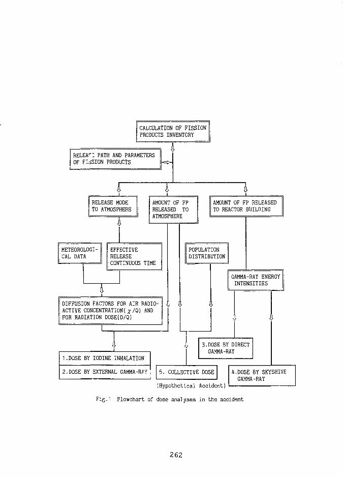
CALCULATION OF FISSIONPRODUCTS INVENTORY
RELEAf" PATH AND PARAMETERSOF FIdSION PRODUCTS
TRELEASE MODETO ATMOSPHERE
TAMOUNT OF FPRELEASED TOATMOSPHERE
METEOROLOGI-CAL DATA
EFFECTIVERELEASECONTINUOUS TIME
DIFFUSION FACTORS FOR AIR RADIO-ACTIVE CONCENTRATION^/Q) ANDFOR RADIATION DOSE(D/Q)
AMOUNT OF FP RELEASEDTO REACTOR BUILDING
POPULATIONDISTRIBUTION
GAMMA-RAY ENERGYINTENSITIES
I1.DOSE BY IODINE INHALATION
2.DOSE BY EXTERNAL GAMMA-RAY
3.DOSE BY DIRECTGAMMA-RAY
5. COLLECTIVE DOSE
(Hypothetical Accident)
.DOSE BY SKYSHINEGAMMA-RAY
Fig.1 Flowchart of dose analyses in the accident
262
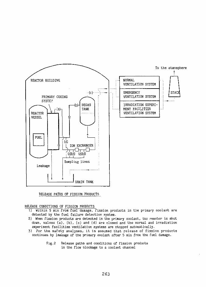
To the atmospheret
REACTOR BUILDING
PRIMARY COOINGSYSTEH
DRAIN TANK
NORMALVENTILATION SYSTEM
EMERGENCYVENTILATION SYSTEM
IRRADIATION EXPERI-MENT FACILITIESVENTILATION SYSTEM
STACK
RELEASE PATHS OF FISSION PRODUCTS
RELEASE CONDITIONS OF FISSION PRODUCTS1) Within 5 min from fuel damage, fission products in the primary coolant aredetected by the fuel failure detection system.
2) When fission products are detected in the primary coolant, the reactor is shutdown, valves (a), (b), (c) and (d) are closed and the normal and irradiationexperiment facilities ventilation systems are stopped automatically.
3) For the safety analyses, it is assumed that release of fission productscontinues by leakage of the primary coolant after 5 min from the fuel damage.
Fig.2 Release paths and conditions of fission productsin the flow blockage to a coolant channel
263
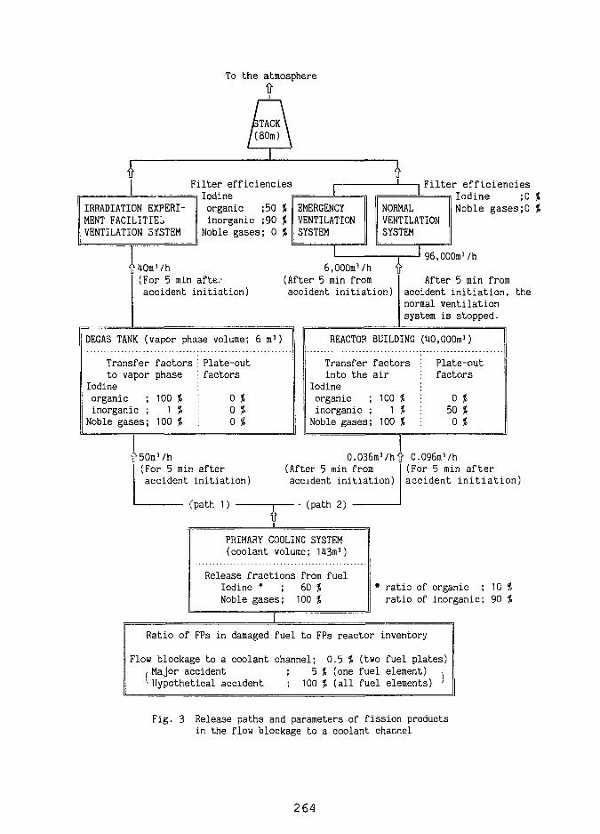
To t h e atmosphere
IRRADIATION EXPERI-MENT FACILITIESVENTILATION SYSTEM
Filter efficienciesIodineorganic ;50 %inorganic ;90 %
Noble gases; 0 %
±EMERGENCYVENTILATIONSYSTEM
Filter efficiencies
NORMALVENTILATIONSYSTEM
L
Iodine ;0 %Noble gases;0 %
(For 5 min afte:-accident initiation)
6,000m3/h(After 5 min fromaccident initiation.)
96,000m3/h
DEGAS TANK (vapor phase volume; 6 m 3 )
Transfer factorsto vapor phase
Iodineorganic ; 100 %inorganic ; 1 %
Noble gases; 100 %
Plate-outfactors
0 (0 *0 %
After 5 min fromaccident initiation,normal ventilationsystem is stopped.
the
REACTOR BUILDING (HO,000m3]
Transferinto the
Iodineorganicinorganicfoble gases
factorsair
100 %1 *
100 %
Plate-outfactors
0 %50 %0 %
ft 50m3/h(For 5 min afteraccident initiation)
0.036m3/h(After 5 min fromaccident initiation)
io.
(path 1) 1 (path 2)
If
096m3/h(For 5 min afteraccident initiation)
PRIMARY COOLING SYSTEM(coolant volume; 143m!)
Release fractions from fuelIodine * ; 60 %Noble gases; 100 %
• ratio of organic ; 10 %ratio of inorganic; 90 %
Ratio of FPs in damaged fuel to FPs reactor inventory
Flow blockage to a coolant channel; 0.5 J (two fuel plates)j-Major accident ; 5 % (one fuel element) ,^Hypothetical accident ; 100 % (all fuel elements) '
Fig. 3 Release paths and parameters of fission productsin the flow blockage to a coolant channel
264
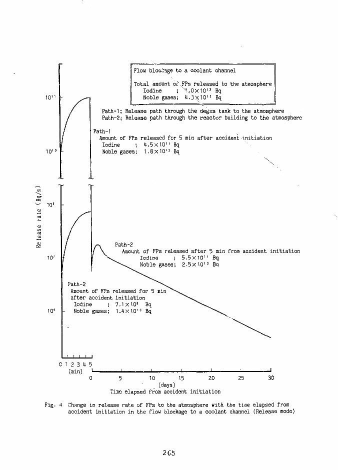
101
10'
Flow blockage to a coolant channel
Total amount of .FPs released to the atmosphereIodine ; X.0X101 2 BqNoble gases; 4.3X10'3 Bq
Path-1; Release path through the degas tank to the atmospherePath-2; Release path through the reactor building to the atmosphere
Path-1Amount of FPs released for 5 min after accident initiationIodine ; 4.5X10" BqNoble gases; 1.8x10¹³ Bq
103
107
Path-2Amount of FPs released after 5 min from accident initiation
Iodine ; 5.5X101 ' BqNoble gases; 2.5X10'3 Ba
106
Path-2Amount of FPs released for 5after accident initiationIodine ; 7.1X10⁸ BqNoble gases; 1.4x10'° Bq
min
0 1 2 3 4 5[min] I-
0 5 10 15 20[days]
Time elapsed from accident initiation
25 30
Fig. 4 Change in release rate of FPs to the atmosphere with the time elapsed fromaccident initiation in the flow blockage to a coolant channel (Release mode)
265
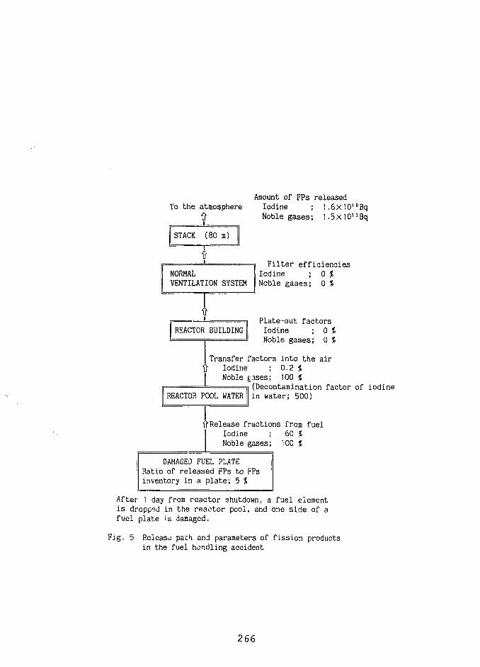
Amount of FPs releasedTo the atmosphere Iodine ; 1.6XiO'°Bq
ft Noble gases; 1.5xiO'3Bq
STACK (80 m)
ft
NORMALVENTILATION SYSTEM
Fil ter efficienciesIodine ; 0 %Noble gases; 0 %
ft
REACTOR BUILDINGPlate-out factorsIodine ; 0 %Noble gases; 0 %
| Transfer factors into the airft Iodine ; 0.2 %| Noble £.ases; 100 %
(Decontamination factor of iodineREACTOR POOL WATER in water; 500)
ft Release fractions from fuelIodine ; 60 %Noble gases; 100 %
DAMAGED FUEL PLATERatio of released FPs to FPsinventory in a plate; 5 %
After 1 day from reactor shutdown, a fuel elementis dropped in the reaotor pool, and one side of afuel plate is damaged.
Fig. 5 Release path and parameters of fission productsin the fuel handling accident
266
EARLY DETECTION OF COOLANT BOILING IN
RESEARCH REACTORS WITH MTR-TYPE FUEL
R. Kozma, E. Turkcan, J.P. Verhoef
Netherlands Energy Research Foundation, Business Unit Nuclear EnergyP.O. Box 1, NL-1775 ZG Petten
The Netherlands
ABSTRACT
In this paper, a reactor core monitoring system having the function of early detection ofboiling in the coolant channels of research reactors with MTR-type fuel is introduced.The system is based on the on-line analysis of signals of various ex-core and in-coreneutron detectors. Early detection of coolant boiling cannot be accomplished by theevaluation of the DC components of these detectors in a number of practically impor-tant cases of boiling anomaly. It is shown that noise component of the available neutrondetector signals can be used for the detection of boiling in these cases. Experimentshave been carried out at a boiling setup in the research reactor HOR of the InterfacultyReactor Institute, Technical University Delft, The Netherlands.
INTRODUCTION
Thermohydraulic conditions in the core of research reactors can change significantly due toHEU —> LEU conversion. Also, safety margins towards onset of boiling vary. The presenceof boiling is undesirable in research reactors, as boiling can easily lead to burnout and consequentmelting of the fuel [1]. Coolant boiling has to be prevented by all means, and, in case of occurrence,it has to be detected as early as possible in order to avoid damage of the reactor core. One ofthe potentially most dangerous events which may lead to coolant boiling is the sudden (partial)blockage of coolant channels. A number of voidage-detection methods is based on monitoringsudden decrease of the neutron flux caused by the negative void effect. Studies performed duringthe implementation of such a method in the research reactor of the Interfaculty Reactor Institute(IRI), TU Delft, The Netherlands, show that an initial reactivity step of 50 pcm, or 5 % of neutronflux decrease was needed in most cases in order to generate trip conditions [21
At the first phase of the development of coolant boiling anomaly, the changes in the neutronflux are not strong enough to initiate reactor trip. At certain disadvantageous positions in the core,moreover, coolant boiling may develop and remain undetected even at a very advanced stage. Bymonitoring the small fluctuations (noise) of the neutron flux around its average value can furnishus with the proper information to detect the anomaly at an early stage. Boiling detection based onneutron noise analysis is introduced in this paper.
267
Research aiming at studying boiling neutron noise has been conducted for years in IRI in theNIOBE project (Noise Investigations On Boiling Effects) [3]. In this research, physical phenom-ena related to boiling in research reactors with plate-type fuels have been analysed thoroughly.Presently, a project has started at ECN, Petten, which aims at the implementation of the resultsobtained at NIOBE for the High Flux Reactor (HFR) in Petten.
HFR uses MTR-type fuel assemblies [4] which are similar to those used at HOR. The fuelassemblies have horizontal cross section 8.1 cm x 7.7 cm and active length of 60 cm both at HFRand HOR. An HFR-assembly contains 23 vertically arranged curved fuel plates, while an assemblyin the HOR has 19 flat fuel plates. The uranium is about 93 % enriched in 235U in both reactors atthe present. A typical core lattice of HFR is a 9 x 9 array with 33 fuel assemblies, while the HORhas a 7 x 6 array with 25 fuel assemblies. The power of HFR is 45 MW, which is much higherthan the power of HOR (2 MW). This higher power at HFR needs more intensive cooling than atHOR. Accordingly, the coolant speed in the fuel assembly is 7 m/s and 0.5 m/s in HFR and HOR,respectively. HOR has narrow coolant channels of width 0.3 cm. The channels of HFR are evennarrower (0.255 cm). Boiling in narrow coolant channels has a few special features analysed indetail during the NIOBE experiments. The peculiar character of boiling in narrow channels hasimportant implications on boiling detection methods in reactors with plate-type fuels.
ECN has experience with on-line monitoring of operational parameters of nuclear reactors,including Borssele PWR, and HFR [5]. In the framework of the present investigations the on-linemonitoring system of ECN has been connected to the boiling setup in HOR during the experimentsfrom May to July, 1992. The results indicate that it is possible to detect coolant channel boiling/voidin NIOBE.
EXPERIMENTS
Experiments have been carried out at the NOIBE boiling setup of IRI. Here, the main proper-ties of this setup are given [6]. NIOBE consists of a simulated MTR-type fuel assembly withina closed coolant lopp, a circulation pump, two flowmeters, and a number of thermocouples andin-core detectors. The simulated assembly has an almost square cross-section (dimension: 7.7 cmx 8.1 cm) and an active length of 62.5 cm; it is located next to the core of HOR. The pump andthe control valves are found at positions above the pool water level.
The simulated fuel assembly has three electrically heated fuel plates. The heating power canbe varied continuously or step-wise by making use of electrical power units at each plate separately.The heating power of a plate can reach a maximum of 7 kW. By varying the heating power of theplates, different levels of coolant boiling can be induced in NIOBE. There arp two coolant channelsin the simulated assembly between plates no. 1 and 2, and plates no. 2 and 3, respectively.The coolant is pumped through the channels with the circulation pump. The flow rate in eachchannel can be adjusted by remote controlled valves. Both coolant channels have a rectangularcross-section of dimensions 6.15 cm x 0.5 cm. The total length of a channel is 62.5 cm.
In the experiments, signals of both incore and excore neutron detectors were used. Excoredetectors are ionisation chambers located around the reactor core. The incoie neutron detectorsare self-powered neutron detectors (SPNDs) with Cd-Mg emitters. SPNDs are arranged in strings.
268
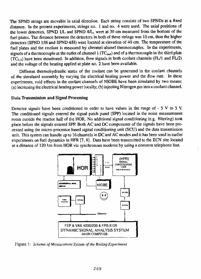
The SPND strings are movable in axial direction. Each string consists of two SPNDs at a fixeddistance. In the present experiments, strings no. 1 and no. 4 were used. The axial positions ofthe lower detectors, SPND 1/L and SPND 4/L, were at 30 cm measured from the bottom of thefuel plates. The distance between the detectors in both of these strings was 10 cm, thus the higherdetectors (SPND 1/H and SPND 4/H) were located at elevation of 40 cm. The temperature of thefuel plates and the coolant is measured by chromel-alumel thermocouples. In the experiments,signals of a thermocouple at the outlet of channel 1 (TCoui) and of a thermocouple in the third plate(TC3.3) have been monitored. In addition, flow signals in both coolant channels (FL/1 and FL/2)and the voltage of the heating applied at plate no. 2 have been available.
Different thermohydraulic states of the coolant can be generated in the coolant channelsof the simulated assembly by varying the electrical heating power and the flow rate. In theseexperiments, void effects in the coolant channels of NIOBE have been simulated by two means:(a) increasing the electrical heating power locally; (b) injecting Nitrogen gas into a coolant channel.
Data Transmission and Signal Processing
Detector signals have been conditioned in order to have values in the range of - 5 V to 5 V.The conditioned signals entered the signal patch panel (SPP) located in the noise measurementroom outside the reactor hall of the HOR. No additional signal conditioning (e.g. filtering) tookplace before the signals entered SPP. Both AC and DC components of the signals have been pro-cessed using the micro-processor based signal conditioning unit (SCU) and the data transmissionunit. This system can handle up to 16 channels in DC and AC modes and it has been used in earlierexperiments on fuel dynamics in HFR [7, 8]. Data have been transmitted to the ECN site locatedat a distance of 120 km from HOR via synchronous modems by using a common telephone line.
HOR
(HFR)SIGNAL
CONDITIONINGUNIT
(micro pcocewr)
NIOBEJVMK j 4 MODEM I
STATION I I
, (Ethernet)
FEP & VAX 4000/200 & FPS-5105DYNAMIC SIGNAL ANALYSIS SYSTEM
-MAIN COMPUTER-
Figure 1: Schema of Measurement System of the Boiling Experiment
269
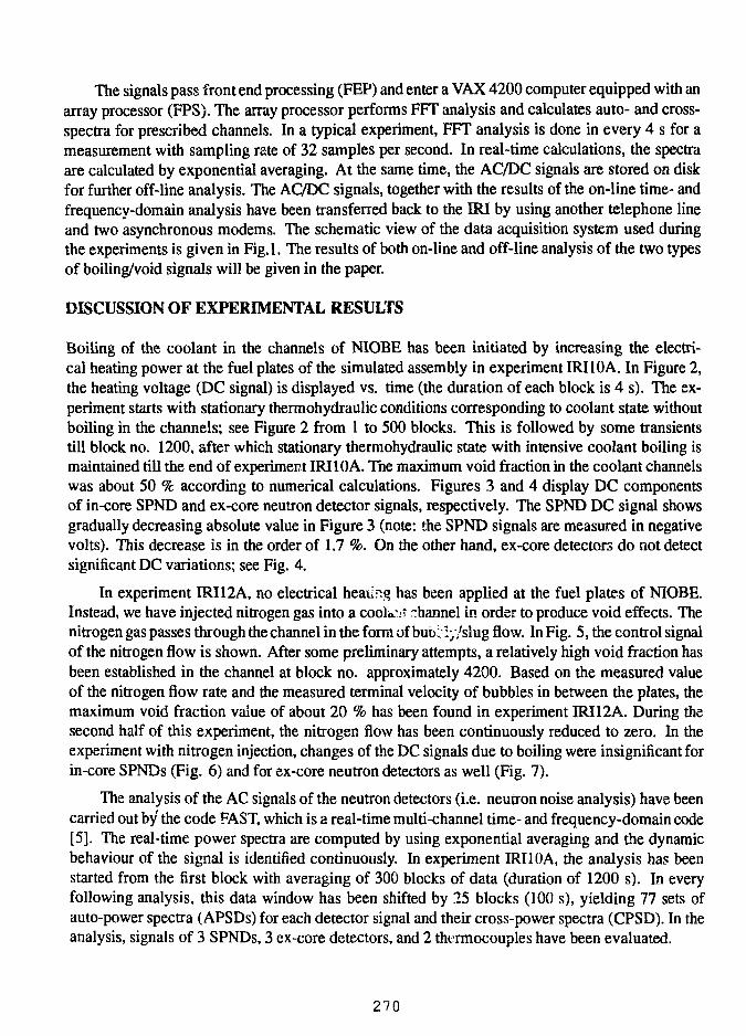
The signals pass front end processing (FEP) and enter a VAX 4200 computer equipped with anarray processor (FPS). The array processor performs FFT analysis and calculates auto- and cross-spectra for prescribed channels. In a typical experiment, FFT analysis is done in every 4 s for ameasurement with sampling rate of 32 samples per second. In real-time calculations, the spectraare calculated by exponential averaging. At the same time, the AC/DC signals are stored on diskfor further off-line analysis. The AC/DC signals, together with the results of the on-line time- andfrequency-domain analysis have been transferred back to the IRI by using another telephone lineand two asynchronous modems. The schematic view of the data acquisition system used duringthe experiments is given in Fig.l. The results of both on-line and off-line analysis of the two typesof boiling/void signals will be given in the paper.
DISCUSSION OF EXPERIMENTAL RESULTS
Boiling of the coolant in the channels of NIOBE has been initiated by increasing the electri-cal heating power at the fuel plates of the simulated assembly in experiment IRI 10A. In Figure 2,the heating voltage (DC signal) is displayed vs. time (the duration of each block is 4 s). The ex-periment starts with stationary thermohydraulic conditions corresponding to coolant state withoutboiling in the channels; see Figure 2 from 1 to 500 blocks. This is followed by some transientstill block no. 1200, after which stationary thermohydraulic state with intensive coolant boiling ismaintained till the end of experiment IRI 10A. The maximum void fraction in the coolant channelswas about 50 % according to numerical calculations. Figures 3 and 4 display DC componentsof in-core SPND and ex-core neutron detector signals, respectively. The SPND DC signal showsgradually decreasing absolute value in Figure 3 (note: the SPND signals are measured in negativevolts). This decrease is in the order of 1.7 %. On the other hand, ex-core detectors do not detectsignificant DC variations; see Fig. 4.
In experiment IRI12A, no electrical heating has been applied at the fuel plates of NIOBE.Instead, we have injected nitrogen gas into a cooler channel in order to produce void effects. Thenitrogen gas passes through the channel in the form of bubr :y/slug flow. In Fig. 5, the control signalof the nitrogen flow is shown. After some preliminary attempts, a relatively high void fraction hasbeen established in the channel at block no. approximately 4200. Based on the measured valueof the nitrogen flow rate and the measured terminal velocity of bubbles in between the plates, themaximum void fraction value of about 20 % has been found in experiment IRI 12A. During thesecond half of this experiment, the nitrogen flow has been continuously reduced to zero. In theexperiment with nitrogen injection, changes of the DC signals due to boiling were insignificant forin-core SPNDs (Fig. 6) and for ex-core neutron detectors as well (Fig. 7).
The analysis of the AC signals of the neutron detectors (i.e. neutron noise analysis) have beencarried out by the code FAST, which is a real-time multi-channel time- and frequency-domain code[5]. The real-time power spectra are computed by using exponential averaging and the dynamicbehaviour of the signal is identified continuously. In experiment IRI10A, the analysis has beenstarted from the first block with averaging of 300 blocks of data (duration of 1200 s). In everyfollowing analysis, this data window has been shifted by 25 blocks (100 s), yielding 77 sets ofauto-power spectra (APSDs) for each detector signal and their cross-power spectra (CPSD). In theanalysis, signals of 3 SPNDs, 3 ex-core detectors, and 2 thtTmocouples have been evaluated.
270
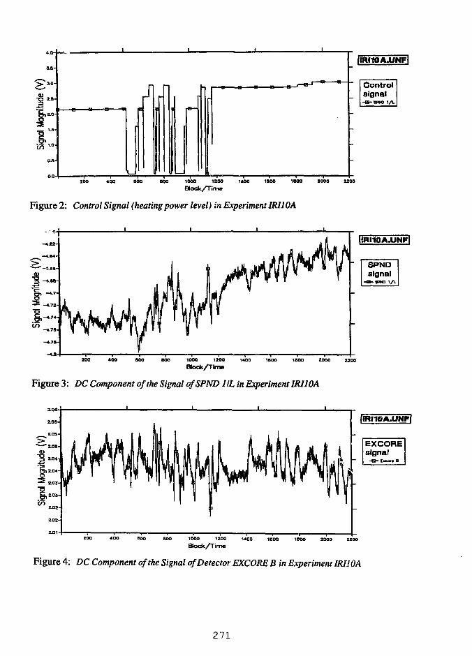
4.1
3.8-
Jl
ItRHOA.UNFl
Controlsignal
200 400 SOD BOO 1000 1200 1400 1900 1B0O 2000 2200
Block/Tirrw
Figure 2: Control Signal (heating power level) in Experiment IRIIOA
200 400 WO BOO 1000 1200 1400 1BOO 1BO0 2000 2200
c75
Figure 3: DC Component of the Signal ofSPND 1IL in Experiment IRIIOA
ZOO 400 BOO BOO 1000 1200 1400 1QOO 1BOO 2000 2200
Figure 4: DC Component of the Signal of Detector EXCORE B in Experiment IRIIOA
271
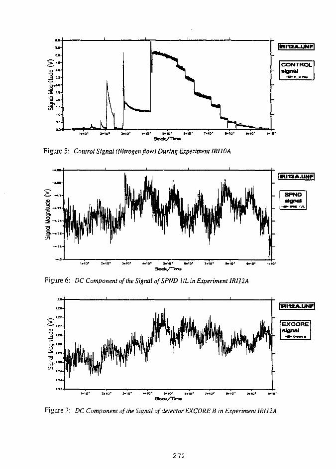
B«10* 1*10'
Figure 5: Control Signal (Nitrogen flow) During Experiment IRIIOA
S»1O* B«10" 7*tO* B*10* 9*10* 1«1C*
Btodk/Twnm
Figure 6: DC Component of the Signal ofSPND IIL in Experiment IRI12A
10* I«IO*
Figure 7: DC Component of the Signal of detector EXCORE B in Experiment IRII2A
272
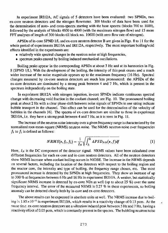
In experiment IRI12A, AC signals of 5 detectors have been evaluated; two SPNDs, twoex-core neutron detectors and the nitrogen flowmeter. 300 blocks of data have been used forthe determination of auto- and cross-spectra starting with the base spectra (blocks 700 to 1000),followed by the analysis of blocks 4600 to 4900 (with the maximum nitrogen flow) and 15 moreFFT analyses of length of 300 blocks till block no. 10600 (with zero flow rate of nitrogen).
APSDs of in-core SPND 1/L and ex-core neutron detector B are given in Figs. 8 to 11 for thewhole period of experiments IRI10A and IRI12A, respectively. The most important boiling/voideffects identified in the experiments are:
• relatively wide spectral changes in the neutron noise at high frequencies,• spectrum peaks caused by boiling induced mechanical oscillations.
Boiling peaks appear in the corresponding APSDs at about 3 Hz and at its harmonics in Fig.8 (SPND 1/L). With the development of the boiling, the intensity of this peak ceases and a muchwider increase of the noise magnitude appears up to the maximum frequency (16 Hz). Spectralchanges measured by ex-core neutron detectors are much less pronounced: the APSDs of theex-core detectors are dominated by a strong peak between 4 and 7 Hz, which is present in thespectrum independently on the boiling state.
In experiment IRI12A with nitrogen injection, in-core SPNDs indicate continuous spectralchange with decreasing void fraction in the coolant channel; see Fig. 10. The pronounced boilingpeak at about 2 Hz with a clear phase-shift between noise signals of SPNDs in one string indicatebubble transport in the channel. This effect can be used for the determination of the velocity ofbubbles in the channels [6]. The spectra of ex-core detectors are similar to those in experimentIRI10A, i.e. they have a strong peak between 4 and 7 Hz, as it is seen in Fig. 11.
The increase of the neutron noise intensity over a given frequency range is characterized by thenormalized root-mean-square (NRMS) neutron noise. The NRMS neutron noise over frequencies/i to / . is defined as follows:
fiJi) = ̂ -Jfh APSDNN{rJ)df (1)
Here, IN is the DC component of the detector signal. NRMS values have been calculated overdifferent frequencies for each ex-core and in-core neutron detectors. All of the neutron detectorsshow NRMS increase when coolant boiling occurs in NIOBE. The increase in the NRMS dependson several factors, including the location of the detectors with respect to the boiling region andthe reactor core, the intensity and type of boiling, the frequency range chosen, etc. The mostpronounced increase is detected by the SPNDs at high frequencies. They show an increase of upto 300 % at frequencies between 6 Hz and 16 Hz in experiment IRI10A. A weaker, but statisticallysignificant NRMS increase is detected by ex-core NDs as well (up to about 25 %) over the samefrequency interval. The error of the measured NRMS is 0.27 % in these experiments, so boilinganomaly can be detected clearly both by in-core and ex-core detectors.
The above results can be expressed in absolute units as well. The NRMS increase due to boil-ing is 1.85 x 10~4 in experiment IRI10A, which results in a reactivity change of 0.13 pcm. At thesame time, ex-core neutron detectors see a vibration induced peak between 5 Hz and 7 Hz, having areactivity effect of 0.05 pcm, which is constantly present in the spectra. The bubbling neutron noise
273
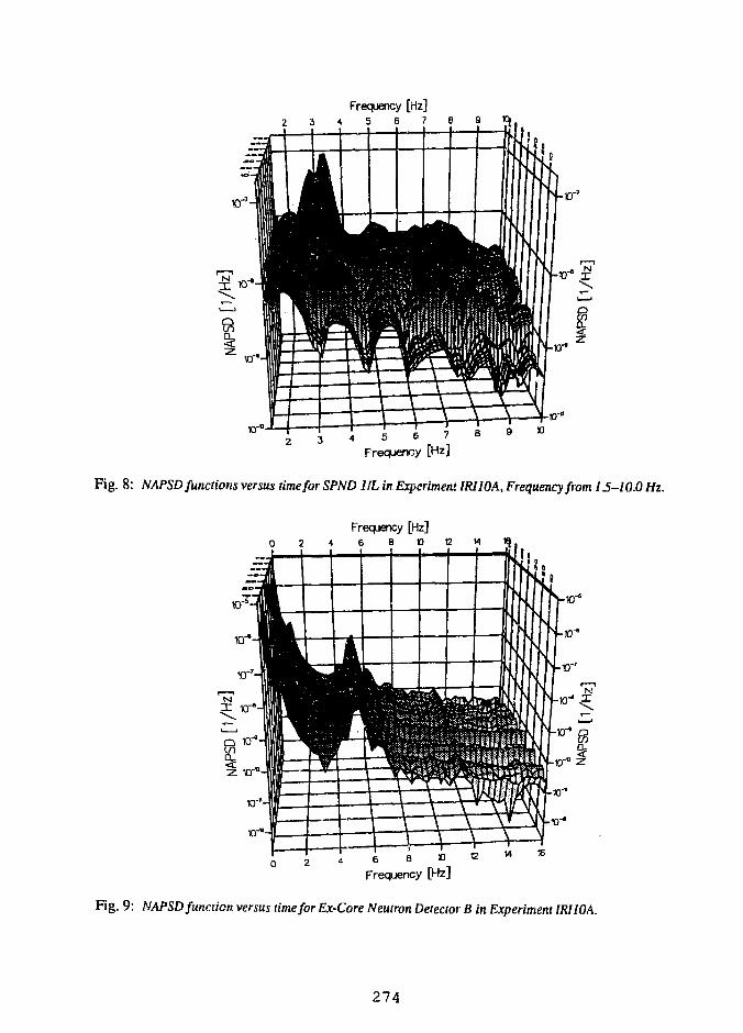
Frequency [Hz]2 3 4 5 6 7 8 9 1 C
4 5 6 7Frequency [Hz]
B 9 »
Fig. 8: NAPSD functions versus time for SPND 1IL in Experiment IRIIOA, Frequency from 15-10.0 Hz.
Frequency [Hz]
Fig. 9: NAPSD function versus time for Ex-Core Neutron Detector B in Experiment IRIIOA.
274
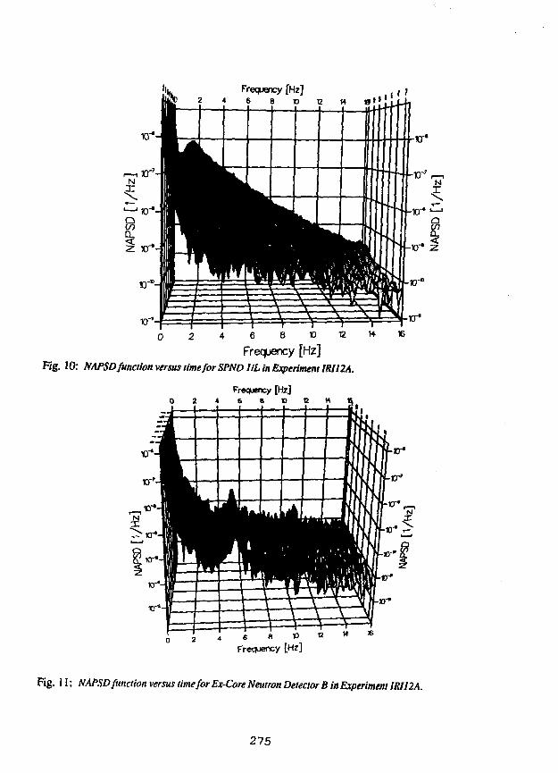
Frequency [Hz]
iff4 6 8 » 12
Frequency [Hz]Fig. 10: NAPSD function versus time for SPND IIL in Experiment IRI12A.
Frequency [Hz]
PRHItmmmwmi
1••
•mi
••n•••
•••
liHI
••••
•HI•••1
Hi•••••
*1,
i0 2 * 6 8 * ,
Frequency [Hz]
Fig. 11: NAPSD function versus time for Ex-Core Neutron Detector B in Experiment JRIJ2A.
215
in experiment IRI12A shows an increase of 1.60x 10"3, which corresponds to 1.12 pcm reactivity.The void fraction value in the coolant channel (maximum of 20 %) evaluated from this reactivityeffect is in good agreement with the actual value determined from the known values of nitrogen flow.
CONCLUDING REMARKS
Results of experiments with coolant boiling in actual reactor environment are presented. Coolantboiling in the channels of a simulated fuel assembly has been detected based on the analysis ofneutron noise. The experiments indicate that even very small amount of void can be detected atthe early stage of boiling in the coolant channels having a reactivity effect of less than 1 pcm. Inthe case of HEU —» LEU conversion at the HFR, the expected modifications in the neutronic andthermohydraulic characteristics of the core may introduce changes in the properties related to theonset of boiling and bubble detachement criteria. The coolant boiling in these circumstances canbe detected at a very early stage by the methodology outlined in this paper.
Although boiling induced variations in the DC component of the neutron detector signals couldnot produce an unambiguous criterion for boiling detection in the case of low level of boiling (voidfraction in two coolant channels below 50 %), but in combination with noise criteria DC analysiscan facilitate early identification of coolant boiling in nuclear reactors. In the recent years, alsoseveral new methods and algorithms have been developed for the identification of changes in signalpatterns either by using DC signals with powerful sequential statistical tests or by applying classicalalgorithms to identify spectral changes in real-time, or by using neural networks as spectral patternclassifiers.
ACKNOWLEDGEMENTS The authors wish to express their appreciations to the Department ofReactor Physics, IRI, Technical University Delft, for their cooperation in this experiment and to theReactor Operation Group of HOR for their help in completing the measurements at the HOR. Specialthanks are due to dr G. J.H. van Nes for his innovations in the graphical representation of the results.
REFERENCES
1. W.L. Woodruff, Nuclear Technology, Vol. 64 (Feb.1984), pp.196-2062. J.W. De Vries, H. Van Dam,and G. Gysler, IAEA-SM-310 (1986), pp.546-5523. J.E. Hoogenboom, B.H. Van Meulenbroek, H. Van Dam, and E.BJ. Kleiss,
Progress in Nuclear Energy (1985) Vol. 15, pp. 771-7794. ROttger, A.Tas, P. von der Hardt, W.P. Voorbraak, High Flux Materials Testing Reactor
HFR Petten, EUR 5700 EN (1986)5. Tiirkcan E., W.HJ.Quaadvliet, T.T.J.M.Peeters, and J.P.Verhoef, ECN-RX-91-057 (1991)
and SMORN VI, May 12-24 (1991),Gatlinburg, TN, USA, Paper 3.01 (1991)6. Kozma R. (1992) Nuclear Reactor Noise Investigations on Boiling Effects in a Simulated
MTR-type Fuel Assembly, Thesis, Delft (1992)7. TUrkcan E., G. Tsotridis, R.L. Moss (1988) Progress in Nuclear Energy, Vol.21, pp. 393-4038. Tiirkcan E. (1988) On-line Monitoring of HFR Operation and Fuel Dyn., in Proc. European
Working Group Irrad. Tech., SCK/CEN Mol, Belgium
276
A Comparison of WIMS-D4 and WIMS-D4m GeneratedCross-section Data with Monte Carlo
W. L. Woodruff, J. R. DeenArgonne National LaboratoryArgonne, Illinois 60439, USA
andC. I. Costescu
University of IllinoisUrbana-Champaign, Illinois 61801, USA
ABSTRACT
Cross-section and related data generated by a modified version ofthe WIMS-D4 code for both plate and rod type research reactor fuelare compared with Monte Carlo data from the VIM code. Themodifications include the introduction of a capability for generatingbroad group microscopic data and to write selected microscopiccross-sections to an ISOTXS file format. The original WIMS-D4library with H in ZrH, and 166Er and 167Er added gives processedmicroscopic cross-section data that agree well with VIM ENDF/B-Vbased data for both plate and TRIGA cells. Additional improvementsare in progress including the capability to generate an ENDF/B-Vbased library
Introduction
The WIMS-D4 code1 has been modified to improve the performance forresearch reactor applications and to produce microscopic cross-sections thatinterface with current codes. This code has been used to generate cross-section datafor both pin and plate type research reactor fuels. These data are compared withMonte Carlo data from the continuous energy VIM code.2
The Codes and Libraries
The original WIMS-D4 code and library were obtained from the Oak RidgeRadiation Shielding Information Center (RSIC). The library contained 101 isotopeswith 69 energy group data. This version of the code uses a single spatial mesh pointfor each region (fuel, clad, coolant and moderator) with the full 69 energy groups inthe initial collision probability solution. This coarse spatial flux is used for theresonance evaluation. These 69 group macroscopic cross-sections are then collapsedover each region to a selected intermediate group structure. These intermediategroup data are used to compute a detailed spatial flux, eigenvalue, i*eaction rates,
277
and to collapse to the selected broad group structure (usually -2-8 groups). The codegives macroscopic cross-sections for each region and a set of cell averaged data. Thecode is capable of treating multicell and cluster models (with rods or plates). Thecode also uses the 69 group coarse spatial flux to collapse regional microscopic cross-sections to the intermediate group structure
The use of this initial flat flux approximation to obtain broad groupmicroscopic data can give poor results for a thick moderator, the extra region in asuper-cell model, and for high absorption regions. The WIMS-D4m version3 of thecode introduces a broad group structure for use in the spatial averaging. Thedetailed spatial flux in the intermedate group structure is used for this purpose. Thisstep is done for the user requested isotopes after the intermediate group averaging ofthe microscopic cross-sections. The broad group microscopic cross-sections may beburnup dependent and averaged over multiple sets of edit cells (groups of regions).These microscopic data are written in the binary ISOTXS format4 in order to becompatible with many of the neutronics codes in the USA .
The original WIMS library has been augmented to include data for hydogen inZrH and the isotopes 166Er and 167Er for TRIGA reactor applications. This library isbased on data generated in the United Kingdom and not ENDF/B data. Acomparison of selected data has found that the WIMS data falls somewhat betweenthe ENDF/B versions IV and V data.
The VIM code uses ENDF/B data to provide a continuous energy Monte Carlosolution for generalized geometry neutron eigenvalue and fixed source problems.These VIM data for this study are based on ENDF/B version V data. The VIM resultsare used here as a standard for comparison of WIMS data. The solutions in each caseinclude 2,000,000 neutron histories to give eigenvalues with standard deviations of+0.0005. The microscopic cross-section data are tallied to match the broad groupstructure of the WIMS model and have uncertainies of less than +0.5% in all casesand less than +0.1% in most cases.
Plate Type Model
The original IAEA benchmark geometry5 has been selected as the basis forthe plate type reactor comparisons. Many research institutions have experience incomputing cross-section data in this three energy group model. The specified modelsfor the standard and control super-cell were used for both the HEU and LEU fuels.The HEU case has the specified loading of 12.17 g 235U/plate with UA1X-A1 fuel. TheLEU case uses U3Si2-Al in a DOE standard fuel plate with a loading of 12.50 g 235U/plate. The HEU super-cell WIMS data are compared with the available data fromthe earlier cases in Table I.
The VIM comparisons for the absorption rates and k-infinity results areshown in Table II. Table III provides a comparison of some of the microscopic dataaveraged over the unit cell. The agreement for absorption rates is excellent, whilethe WIMS k-infinity for HEU shows a bias of almost -0.7%. In Table III, the threegroup spectra show some small differences with the largest for group 1 of thestandard HEU cell at -2.2%. The microscopic cross-section data also show some
278
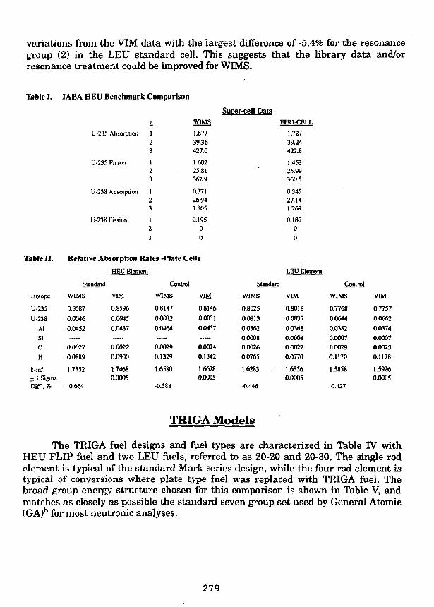
variations from the VIM data with the largest difference of-5.4% for the resonancegroup (2) in the LEU standard cell. This suggests that the library data and/orresonance treatment coald be improved for WIMS.
Table I. IAEA HEU Benchmark Comparison
iblell.
Isotope
U-235
U-238
AlSiO
H
k-inf.+ 1 SigmaDifT. %
U-235 Absorption
U-235 Fisson
U-238 Absorption
U-238 Fission
Relative Absorption
£
123
123
123
123
WIMS
1.87739.36427.0
1.60225.81362.9
0.37126.941.805
0.1950
0
Rates -Plate Cells
HEU Element
Standard
WIMS VIM
0.8587 0.8596
0.0046 0.0045
0.0452 0.0437
0.0027 0.0022
0.0889 0.0900
1.7352 1.74680.0005
-0.664
Control
WIMS
0.8147
0.0032
0.0464
0.0029
0.1329
1.6580
-0.588
VIM
0.8146
0.0031
0.0457
0.0024
0.1342
1.66780.0005
Super-cell DataEPRl-CELL
Standard
WIMS
O.802S
0.0813
0.0362
0.00080.0026
0.0765
1.6283
-0.446
1.72739.24422.8
1.45325.99360.5
0.34527.141.769
0.18000
LEU Element
VIM
0.8018
0.0837
0.0348
0.00080.0022
0.0770
1.63560.0005
Control
WIMS
0.7768
0.0644
0.03820.00070.00290.1170
1.5858
-0.427
VIM
0.77S7
0.0662
0.0374
0.00070.00230.1178
1.59260.0005
TRIGA Models
The TRIGA fuel designs and fuel types are characterized in Table IV withHEU FLIP fuel and two LEU fuels, referred to as 20-20 and 20-30. The single rodelement is typical of the standard Mark series design, while the four rod element istypical of conversions where plate type fuel was replaced with TRIGA fuel. Thebroad group energy structure chosen for this comparison is shown in Table V, andmatches as closely as possible the standard seven group set used by General Atomic(GA)6 for most neutronic analyses.
279
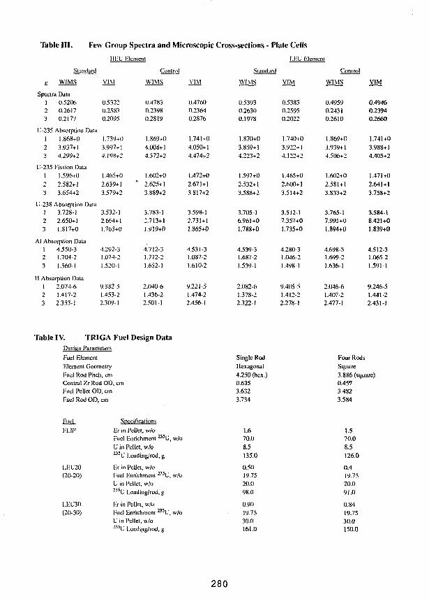
Table III. Few Group Spectra and Microscopic Cross-sections - Plate Cells
Standard
u WIMS
Spectra Dala1 0.52062 0.26173 0.2177
U-235 Absorption Data1 1.868+02 3.937+13 4.299+2
U-235 Fission Dala1 1.596+02 2.582+13 3.654+2
U-238 Absorption DataI 3.728-12 2.650+13 1.SI7+0
AJ Absorption Dala1 4.550-32 1.704-23 1.560-1
H Absorption Dala1 2.074-62 1.417-23 2.353-1
I1F.U
VIM
0.53220.25 S30.2095
1.739+03.997+14.198+2
1.465+02.639+13.579+2
3.532-12.664+11.763+0
4.292-31.074-21.520-1
9.3S2-51.453-22.309-1
Hlcment
Control
WIMS
0.47830.23980.2819
1.869+04.008+14.572+2
1.602+0* 2.625+1
3.889+2
3.783-12.713+1i.919+0
4.712-31.712-21.652-1
2.040-61.436-22.501-1
VIM
0.47600.23640.2876
1.741+04.050+14.474+2
1.472+02.671 + 13.817+2
3.598-12.731+11.865+0
4.531-31.087-21.610-2
9.221-51.474-22.456-1
Slamhrd
WIMS
0.53930.2630O.I97S
1.870+03.859+14.223+2
1.597+02.532+13.588+2
3.705-16.961+01.788+0
4.539-31.687-21.539-1
2.082-61.378-22.322-1
I.F.C 1-
VIM
0.53830.25950.2022
1.740+03.922+14.122+2
1.465+02.600+13.514+2
3.512-17.357+01.735+0
4.280-31.046-21.498-1
9.405-51.412-22.278-1
lenient
Conlrol
Wl.MS
0.49590.24310.2610
1.869+03.939+14.506+2
1.602+02.581 + 13.833+2
3.765-17.991+01.894+0
4.698-31.699-21.636-1
2.046-61.407-22.477-1
VIM
0.49460.23940.2660
1.741+03.988+14.405+2
1.471+02.641+13.758+2
3.584-18.421+01.839+0
4.512-31.065-21.591-1
9.246-51.441-22.431-i
Table IV. TRIGA Fuel Design DataDesiun ParametersFuel ElementKletnenl GeometryFuel Rod Pilch, cmCentral Zr Rod ODFuel Pellel OD, cmFuel Rod OD, cm
Fuel
I-'UP
I.I-U20(20-20)
, cm
Specifications
Kr in Pellel, w/oFuel F-nrichmcnl a 5 U, w/oU in Pellet, w/o235U l.oadiiig/rod, g
F.r in Pellet, w/oFuel l-jtrichmcnt 235V, w/o
(20-30)
U in Pellet, w/o235U Loading/rod, g
l> in Pellel, w/oF'uel linrichmenl 235U, w/oU in Pellel, w/oB 5 U ljuading/rod, g
Single RodHexagonal4.250 (hex.)0.6353.6323.734
1.670.08.5135.0
0.50
19.75
20.0
98.(1
0.90
19.75
30.0
161.0
Four RodsSquare3.886 (square)0.45V3.4823.584
1.570.08.5126.0
0.4
19.75
20.0
91.0
0.8419.7530.0150.0
280

Table V. Broad Group Energy Structure -TRIGA
Upper Bound of Energy Group. cV
1.000+75.000+59.118+31.1230.4000.140
0.050
QA
1.49+76.08+59.12+31.1250.4200.140
0.050
Table VI.
Isotope
L-235
t-238
IM66
Erl67
11 in ZrH
11 in H2O
Zr in ZrH
l-e
Cr
Ni
O
k-inf.+ 1 SigmaDiff., %
Table VII.
Isolopc
U-235
U-238
Iir166
&I67
!lin ZrH
! I in 1120
ZrinZrll
R-Cr
Ni
O
k-inf.+ 1 SigmaDiff.. <il
Relative AbsorptionHEL
WIMS
0.6752
0.0272
0.0101
0.1988
0.0196
0.0191
0.0252
0.0145
0.0050
0.0037
0.0009
1.3260
-1.045
Relative Absorption
HEf
WIMS
0.6857
0.0263
0.0093
0.1856
0.0200
0.0232
0.O23S
0.0154
0.0053
0.0039
0.0010
1.3507
-0.801
Rates
VIM
0.6787
0.0281
0.0105
0.1986
0.0197
0.0189
0.020S
0.0144
0.0051
0.00360.0007
1.34000.0005
Rates
VIM
0.6872
0.0270
0.0095
0.1844
0.0201
0.0256
0.0202
0.0153
0.0054
0.0038
0.0008
1.36160.0005
- Single Rod TRIGALEU 20
WIMS
0.6939
0.0925
0.0045
0.0930
0.02710.0254
0.0278
0.0194
0.0067
0.00490.0009
1.3922
-1.171
- Four Rod TRIGA
LEU 20
WIMS
0.7017
0.0890
0.0039
0.0814
0.0286
0.0303
0.0277
0.0206
0.0071
0.0052
0.0009
1.4116
-0.968
VIM
0.6974
0.0935
0.0046
0.0924
0.0272
0.0251
0.0231
0.0192
00067
0.0047
0.0007
1.40870.0005
VIM
0.7039
0.0893
0.0039
0.0804
0.0287
0.0326
0.0233
0.0203
0.0071
0.0050
0.0008
1.42540.0005
LEU 30
WIMS
0.6754
0.1119
0.0065
0.1263
0.0147
0.0167
0.0225
0.0125
0.0043
0.0032
0.0009
1.3383
-0.925
LEU 30
WIMS
0.6857
0.1084
0.0059
0.1162
0.0 ISO
0.0202
0.0218
0.0133
0..0046
0.0034
0.0010
1.3622
•0.801
VIM
0.6774
0.1132
0.0067
0.1269
0.0148
0.0162
0.0182
0.0122
0.0043
0.0031
0.0008
1.35080.0005
VIM
0.6873
0.1088
0.0061
0.1159
0.0151
0.0222
0.0176
0.0131
0.0046
0.0033
0.0010
1.37320.0005
281
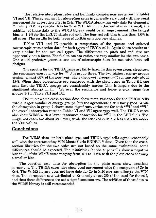
The relative absorption rates and k-infinity comparisons are given in TablesVI and VII. The agreement for absorption rates is generally very good v ith the worstagreement for absorption of Zr in ZrH. The WIMS library has only data for elementalZr, while VIM has specific data for Zr in ZrH. Although the contribution is small, theaddition of these data to the WIMS library would be an improvement. The largestbias is -1.2% for the LEU20 single rod cell. The four rod cell bias is less than 1.0% inall cases. The results for both types of TRIGA cells are very similar.
Tables VIII and IX provide a comparison of the spectra and selectedmicroscopic cross-section data for both types of TRIGA cells. Again these results arevery similar for the two cell types. The differences in pitch and rod size areapparently not a factor. The fuel to coolant ratios are very similar for the two cases.One could probably generate one set of microscopic data for use with both celldesigns.
The spectra for the TRIGA cases are fairly hard. In this seven group structure,the resonance energy group for 238U is group three. The two highest energy groupscontain almost 60% of the neutrons, while the lowest groups (4-7) contain only about13%. When these percentages are compared with the plate cases in Table III, onesees that the TRIGA spectra are considerably harder. This is largely due to thesignificant absorption in 167Er over the resonance and lower energy range (seegroups 3-7 in Table VIII and DO.
The microscopic cross-section data show more variation for the TRIGA cellswith a larger number of energy groups, but the agreement is still fairly good. Whilethe absorption in group 2 shows some significant variations for both 2a^5U and 238U,the overall absorption rates in Tables VI and VII agree very well. The TRIGA casesalso show WIMS with a lower resonance absorption for 238U in the LEU fuels. Thesingle rod cases are about 4% lower, while the four rod cells are less than 3% underthe VIM values.
Conclusions
The WIMS data for both plate type and TRIGA type cells agree reasonablywell with the corresponding VIM Monte Carlo ENDF/B-V data. Given that the cross-section libraries for the two codes are not based on the same evaluations, somedifferences should be expected. The k-innnities for the super-cells show a negativebias in all of the WIMS cases ranging from -0.4 to -1.2% with the plate cases showinga smaller bias.
The reaction rate data for absorption in the plate cases show excellentagreement. The TRIGA cases also show good agreement with the exception of Zr inZrH. The WIMS library does not have data for Zr in ZrH corresponding to the VIMdata. The absorption rate attributed to Zr is only about 2% of the total for the cell,and thus these differences are not a significant concern. The addition of these data tothe WIMS library is still recommended.
282
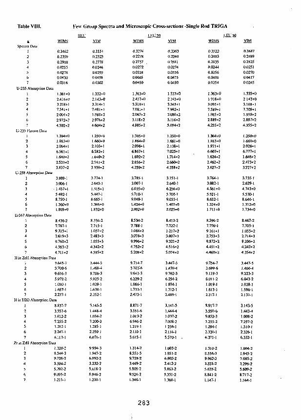
Table VUI.
£Spectra Data
12345(>7
U-235 Absorption Data123456•7
L-235 l-ission Daia1234567
C-238 Absorption Data1234567
ErI67 Absorption Data1234
56-
I'ew (i
Wl.MS
0.34620.23590.290U0.02550.02780.04300.0316
i
1.361+02.416+03.258+17.541 + 12.004+22.972+24.502+2
1.304+01.863+(I2.064+16.561+11.640+22.533+23.837+2
3.809-13.006-1
• 1.437+15.492-18.7S0-11.360+01.809+0
8.436-27.787-19.315+12.619+39.760+24.563+24.711+2
H in ZrH Absorption Data1234567
9.645-73.700-69.616-35.972-21.030-11.657-12.237-1
H in 1120 Absorption Data1234567
8.837-7
3.557-61.012-27.255-21.2S2-12.247-16.117-1
7.x in ZrH Absorption Data123
5
67
1-320-28.544-39.726-23.304-25.702-29.095-21.215-1
rmip Spectra and Microscopic Cross-sections -Single Rod T R I G A
VIM
0.35540.23230.277S0.02460.02990.04980.0302
1.332+02.143+03.314+17.481+11.988+22.976+24.604+2
1.250+01.660+02.103+16.582+11.640+22.S41+23.939+2
3.774-12643-11.515+15.-I47-18.665-11.346+01.832+0
8.334-27.715-11.057+22.483+31.055+34.342+24.595+2
3.444-51.469-49.706-35.925-21.029-11-638-12.252-1
3.145-51.448-41.1)34-27.200-21.285-12.250-16.076-1
9.994-31.945-26.892-23.232-25.618-28.946-21.230-1
UUJ 20W1MS
0.32740.22780.27370.02720.03240.06650.0450
1.363+02.417+03.318+17.S81+12.067+23.118+24.985+2
1.305+0! 864+02.096+16.867+11.692+22656+24.250+2
3.785-13.007-16.035+05.710-19.048-11.424+02.002+0
8.534-27.788-11.086+23.078+39.996+24.752+25.208+2
9.714-73.703:69.641-36.229-21.066-11.733-12.473-1
8.871-73.551-61.013-26.946-21.219-12110-15.615-1
1.314-28.551-39.728-23.449-25.905-29.526-21.346-1
VIM
0.33630.22400.26810.02740.03360.06750.0430
1.333+02.145+03.365+17.992+12.080+23.116+25.094+2
1.250+01.661+02.138+17.025+11.714+22.660+24.358+2
3.751-12.640-!6.256+05.70E-19.033-11.407+02.025+0
8.413-27.723-11.217+23.007+39.321+24.516+25.074+2
3.447-51.470-49.762-36.254-21074-11.712-12.489-1
3.141-51.444-41.037-27.008-21.236-12.116-15.570-1 .
1.003-21.951-26.902-23.412-25.863-29.351-21.360-1
I-Ei: 30WIMS
0.35220.24830.28350.02440.02560.04060.0254
1.363+01.918+03.095+17.589+11.985+22.889+24.255+2
1.304+01.863+01.971+16.607+11.624+22.462+23.627+2
3.764-13.002-14361+05.521-18.652-11.324+01.711+0
8.596-27.770-19.161+12.753+39.872+24.451+24.460+2
9.754-73.699-69.119-36.011-21.019-11.613-12.117-1
8.917-73.550-69.852-37.255-21.294-12.330-16.371-1
1.310-28.556-39.962-23.325-25.635-28.841-21.147-1
VIM
0.36870.24890.28250.02510.02700.04170.0245
1.333+02.143+03.168+17.709+11.998+22.897+24.355+2
1.250+01.660+02.026+16.777+11.646+22.473+23.727+2
3.735-12.629-14.743+05.530-18.646-11.312+01.734+0
8.467-27.705-11.055+22.714+39.206+24.243+24.354+2
3.447-51.466-49.223-36.043-21.028-11.596-12.131-1
3.143-51.443-41.008-27.297-21.310-12.326-16.332-1
1.00421.945-27.085-23.296-25.609-28.717-21.164-1
283
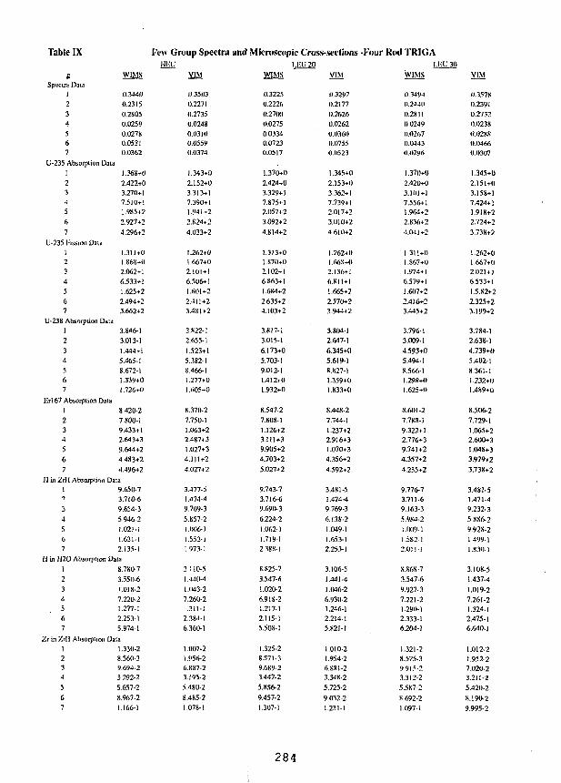
Table IX Few Group Spectra and Microscopic Cross-sections -I-'our Kod TRKiAIIi;C 1.I-U20 I.IX'30
VIM W1MS VIM
Speara Dau1
2
3a.
567
U-235 Absorplion Dala1
2345
6
7
U-235 l-'ission Dala123
4
567
U-238 Absorplion Data1
234567
ET167 Absorplion Data1
234
5
67
0.3440
0.23150.2S050.02590.027S0.05310.0362
1.36S+0
2.422+03.270+17.510+11.985+2
2.927+2
4.296+2
1.311+01.868+02.062+1(S.533+11.625+2
2.494+23.662+2
3.846-13.013-1
1.444+i
5.465-18.672-11.339+01.726+0
8.420-2
7.S00-19.433+12.643+3
9.644+24.483+2
4.496+2
H in ZrH Absorption Data19
3
4
567
9.650-73.710-69.654-3
5.946-21.021-11.631-12.135-1
H in H2O Absorplion Dala1
2
345
67
8.7S0-73.550-6
1.018-2
7.220-21.277-1
2.253-15.974-1
Zr in ZrH Absorplion Dala1234
5
67
1.330-28.560-39.694-23.292-2
5.657-2
8.967-21.166-1
0.35030.22710.27350.02480.03100.05590.0374
1.343+02.152+03.313+17.390+11.941+22.S24+24.033+2
1.262+01.667+02.101 + 16.506+11.601+22.411+23.481+2
3.822-12.655-11.523+15.382-18.466-11.277+01.605+0
8.370-27.750-11.063+22.4S7+31.027+34.111+24.027+2
3.477-51.474-49.709-35.857-2I.006-)1.553-11.973-1
3.110-51.440-41.(143-27.260-2
.311-12.384-16.360-1
1.007-21.956-26.887-23.195-25.480-28.485-21.078-1
0.32250.22260.270(10.02750.03340.07230.0517
1.370+02.424+03.329+17.875+12.057+23.092+24.S14+2
1.313+01.870+02.102+16.863+11.684+22.635+24.103+2
3.817-13.015-16.173+05.703-19.012-11.412+01.932+0
8.547-27.808-11.126+23.111+39.905+24.703+25.027+2
9.743-73.716-69.690-36.224-21.062-11.719-12.3SS-1
8.S25-73.547-61.020-26.91 S-21.217-12.115-15.508-1
1.325-28.571-39.689-23.447-25.886-29.457-21.307-1
0.32970.21770.26260.02620.036(10.07550.OS23
1.345+02.153+03.362+17.739+12.017+23.010+24 610+2
1.262+01.668+02.136+16.811+11.665+22.570+23.944+2
3.804-12.647-16.345+n5.619-18.827-11.359+01.833+0
S.448-27.744-11.237+22.916+31.070+34.356+24.592+2
3.481-51.474-49.769-36.138-21.049-11.653-12.253-1
3.106-51.441-41.046-26.930-21.246-12.214-15.821-I
1.010-21.954-26.881-23.348-25.725-29 032-21.231-1
WIMS
0.34940.2440
0.2811
0 02490.02670.IM430.0296
1.370+02.420+03.101+17.556+11.964+22.836+2
4.M1+2
1.311+01.867+01.974+1
6.579+11.607+2
2.4)6+23.445+2
3.796-1
3.009-14.593+05.494-1
S.566-11.29K+O1.625+0
S.fiOI-27.7SS-I
9.322+12.776+39.741+24.357+2
4.235+2
9.776-73.711-69.163-3
5.9S4-2
1.1X19-11.582-12.0)1-1
S.S6S-7
3.547-6
9.927-3
7.221-21.290-12.333-16.204-1
1.321-28.575-39/J15-23.312-2
5.587-2
8 692-21.097-1
VIM
0.35780.23910.27320.0238
0.02880.04660.0307
1.345+0
2.151+03.158+17.424+11.91 S+22.724+23.738+2
1.262+01.667+02.1)21+)6.533+1
1.5.82+2
2325+23.199+2
3.784-1
2.638-1
4.739+0
5.402-18.361-1
!.232+1)1.489+0
8.506-2
7.729-1
1.065+22.600+31.048+33.979+2
3.738+2
3.4S1-51.471-49.232-3
5.XS6-2
9.92S-21.499-11.830-1
3.108-51.437-4
1.019-2
7.261-21.324-1
2.475-16.640-1
1.012-21.952-27.020.23.211-2
5.420-2
S.I 90-2
9.995-2
284
The WIMS microscopic absorption cross-sections for 238U jn the resonancerange are lower by more than 5% for the LEU plate cases and by about 4% for theTRIGA cases. The addition of ENDF/B-V data to correspond to that in VIM mayresolve some of the differences noted. The overall absorption rate does not seem to bestrongly affected by the differences observed in the microscopic data.
This improved version of the WIMS-D4 code gives a respectable set of datawith the current library for both plate and rod type fuel. The code provides andoption for generating microscopic cross-sections in the ISOTXS format to interfacewith neutoonics codes using this format. The code is also capable of generatingmacroscopic data averaged over selected regions. Further improvements in the codeare in progress including 2D transport and treatments for non-latticeheterogeneities (experiments, control rods, reflectors, etc.). A new all ENDF/B-Vlibrary will be generated in the near future with the inclusion of additional desiredmaterials.
References
1. "Documentation for CCC-576/WIMS-D4 Code Package," RSIC Computer CodeCollection, Oak Ridge National Laboratory, Dec. 1990
2. R. Bloomquist, "VIM - A Continuous Energy Neutronics and Photon TransportCode," ANS Proceedings of the Topical Meeting on Advances inReactorComputations, Salt Lake City, Utah, pp. 222-224, Mar. 1983
3. WIMS-D4M Manual (to be published)
4. "Standard Interface Files and Procedures for Reactor Physics Codes, .Version III," Compiled by B. M. Carmichael, LA-5486-MS, pp. 8-13, Feb. 1974
5. "Research Reactor Core Conversion from the Use of Highly EnrichedUranium to the Use of Low Enriched Uranium Fuels - Guidbook,"IAEA-TECDOC-233, pp. 60-71 and pp. 447-628, 1980
6. IAEA-TECDOC-233, p. 264
285
S E S S I O N V I I I
September 30, 1992
CORE CONVERSION STUDIES
Chairman:
G. Thamm(KFA, Germany)
287
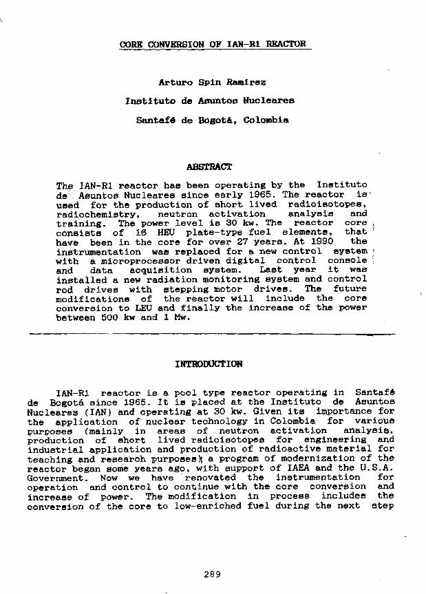
CORK CONVERSION OF IAH-R1 REACTOR
Arturo Spin Ramirez
Inatituto de Asuntos Hucleares
Santafe de Bogota, Colombia
ABSTRACT
The IAN-Ri reactor has been operating by the Institutode Asuntos Nucleares since early 1965. The reactor is-used for the production of short lived radioisotopes,radiochemistry, neutron activation analysis andtraining. The power level is 30 kw. The reactor coreconsists of 16 HEU plate-type fuel elements, thathave been in the core for over 27 years. At 1990 theinstrumentation was replaced for a new control systemwith a microprocessor driven digital control consoleand data acquisition system. Last year it wasinstalled a new radiation monitoring system and controlrod drives with stepping motor drives. The futuremodifications of the reactor will include the coreconversion to LEU and finally the increase of the powerbetween 500 kw and 1 Mw.
INTRODUCTION
IAN-RI reactor is a pool type reactor operating in Santafede Bogota Bince 1965. It is placed at the Instituto de AsuntosNucleares (IAN) and operating at 30 kw. Given its importance forthe application of nuclear technology in Colombia for variouspurposes (mainly in areas of neutron activation analysis,production of short lived radioisotopes for engineering andindustrial application and production of radioactive material forteaching and research purposes)} a program of modernization of thereactor began some years ago, with support of IAEA and the U.S.A.Government. Now we have renovated the instrumentation foroperation and control to continue with the core conversion andincrease of power. The modification in process includes theconversion of the core to low-enriched fuel during the next step
289
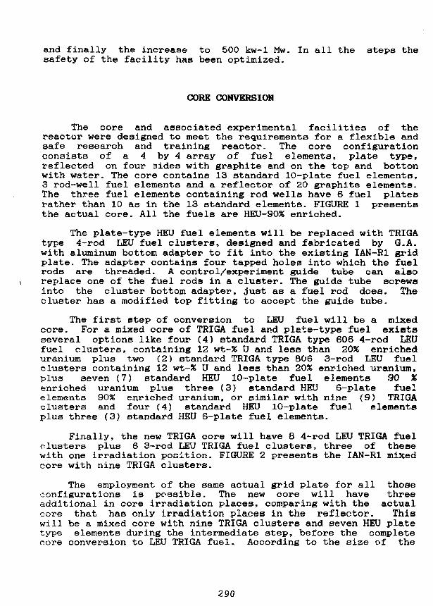
and finally the increase to 500 kw-1 Mw. In all the steps thesafety of the facility has been optimized.
CORE CONVERSION
The core and associated experimental facilities of thereactor were designed to meet the requirements for a flexible andsafe research and training reactor. The core configurationconsists of a 4 by 4 array of fuel elements, plate type,reflected on four 3ides with graphite and on the top and bottonwith water. The core contains 13 standard 10-plate fuel elements,3 rod-well fuel elements and a reflector of 20 graphite elements.The three fuel elements containing rod wells have 6 fuel platesrather than 10 as in the 13 standard elements. FIGURE 1 presentsthe actual core. All the fuels are HEU-90% enriched.
The plate-type HEU fuel elements will be replaced with TRIGAtype 4-rod LEU fuel clusters, designed and fabricated by G.A.with aluminum bottom adapter to fit into the existing IAN-R1 gridplate. The adapter contains four tapped holes into which the fuelrods are threaded. A control/experiment guide tube can alaoreplace one of the fuel rods in a cluster. The guide tube screwsinto the cluster bottom adapter, just as a fuel rod does. Thecluster has a modified top fitting to accept the guide tube.
The first step of conversion to LEU fuel will be a mixedcore. For a mixed core of TRIGA fuel and plate-type fuel existsseveral options like four (4) standard TRIGA type 606 4-rod LEUfuel clusters, containing 12 wt-% U and less than 20% enricheduranium plus two (2) standard TRIGA type 806 3-rod LEU fuelclusters containing 12 wt-% U and less than 20% enriched uranium,plus seven (7) standard HEU 10-plate fuel elements 90 %enriched uranium plus three (3) standard HEU 6-plate fuelelements 90% enriched uranium, or similar with nine (9) TRIGAclusters and four (4) standard HEU 10-plate fuel elementsplus three (3) standard HEU 6-plate fuel elements.
Finally, the new TRIGA core will have 8 4-rod LEU TRIGA fuelclusters plus 6 3-rod LEU TRIGA fuel clusters, three of thesewith one irradiation position. FIGURE 2 presents the IAN-R1 mixedcore with nine TRIGA clusters.
The employment of the same actual grid plate for all thoseconfigurations is possible. The new core will have threeadditional in core irradiation places, comparing with the actualcore that has only irradiation places in the reflector. Thiswill be a mixed core with nine TRIGA clusters and seven HEU platetype elements during the intermediate step, before the completecore conversion to LEU TRIGA fuel.. According to the size of the
290
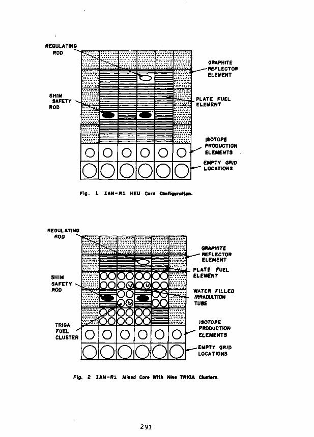
REGULATINGROD ^
SHIMSAFETY
ROD «!*£
O
OoO
oO
o oOO
VMVH;
oO
GRAPHITE-REFLECTOR
ELEMENT
PLATE FUELELEMENT
ISOTOPEPRODUCTIONELEMENTS
EMPTY GRIDLOCATIONS
Fig. 1 I A N - R 1 HEU Cor* Conf (gyration.
REGULATINGROD
TRIGAFUEL *"CLUSTER O o
HDQQQQQsO
OOOOo o o
OO
GRAPHITEREFLECTORELEMENT
PLATE FUELELEMENT
WATER FILLEDIRRADIATIONTUBE
ISOTOPEPRODUCTIONELEMENTS
• EMPTY GRIDLOCATIONS
Fig. 2 I A N - R 1 Mix*d Cor* With Nbt* TRIGA Clutter*.
291
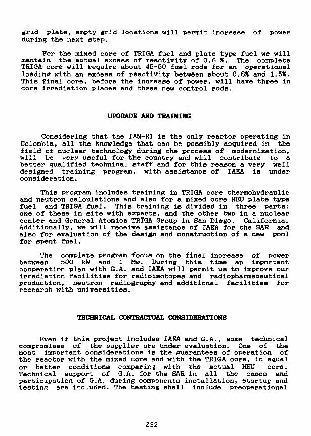
grid plate, empty grid locations will permit increase of powerduring the next step.
For the mixed core of TRIGA fuel and plate type fuel we willmantain the actual excess of reactivity of 0.6 %. The completeTRIGA core will require about 45-50 fuel rods for an operationalloading with an excess of reactivity between about 0.6% and 1.5%.This final core, before the increase of power, will have three incore irradiation places and three new control rods.
UPGRADE AND TRAINING
Considering that the IAN-R1 io the only reactor operating inColombia, all the knowledge that can be possibly acquired in thefield of nuclear technology during the process of modernization,will be very useful for the country and will contribute to abetter qualified technical staff and for this reason a very welldesigned training program, with assistance of IAEA is undercons iderat ion.
This program includes training in TRIGA core thermohydraulicand neutron calculations and also for a mixed core HEU plate typefuel and TRIGA fuel. This training is divided in three parts:one of these in site with experts, and the other two in a nuclearcenter and General Atomics TRIGA Group in San Diego, California.Additionally, we will receive assistance of IAEA for the SAR andalso for evaluation of the design and construction of a new poolfor spent fuel.
The complete program focus on the final increase of powerbetween 500 kW and 1 Mw. During this time an importantcooperation plan with G.A. and IAEA will permit us to improve ourirradiation facilities for radioisotopes and radiopharmaceuticalproduction, neutron radiography and additional facilities forresearch with universities.
TECHNICAL CONTRACTUAL CONSIDERATIONS
Even if this project includes IAEA and G.A., some technicalcompromises of the supplier are under evaluation. One of themost important considerations is the guarantees of operation ofthe reactor with the mixed core arid with the TRIGA core, in equalor better conditions comparing with the actual HEU core.Technical support of G.A. for the SAR in all the cases andparticipation of G.A. during components installation, startup andtesting are included. The testing shall include preoperational
292
testing, initial startup of the reactor, adjustment of excessreactivity, control rod calibration and operation of the reactor,at its steady-state power level for a continuous period of eighthours. An proper execution of procedures will be defined betweenIAN and G.A. with assistance of IAEA. Safety procedures andevaluation of the safety will be considered as first priority.
OTHER ACTIVITIES WITH ASSISTANCE OF IAEAAND THE U.S.A. GOVERNMENT
The modernization of the IAN-R1 reactor has included untilnow, the renewal of the instrumentation for a new control systemwith microprocessor driven digital control console and dataacquisition system, the replacement of the control rod drives andthe installation of a new radiation monitoring system. Technicalassistance for all these steps has been very useful to the IAN.
CONCLUSION
After the complete proceBS of core conversion to LEU, theIAN-R1 reactor will be in the best conditions to increase itspower between 500 kw and 1 Mw. During all this preliminarysteps, we have obtained important experience and knowledge thatwill certainly help us finding better possibilities for theColombian reactor and for the nuclear industry.
29:
STATUS OF THE BERII,
A. Axmann, H. Buchholz. CO. Fischer and H. KrohnHahn-Meitner-Institut Berlin
ABSTRACT
The BER II could start the operation with high enriched materials after ashut-down period for upgrading procedures. The application for the use oflow enriched fuel was submitted to the authority. Whereas all data for aLEU core are evaluated, HEU-LEU mixed fuel elements are still underinvestigation. A licencing problem occurs with the open back end of thefuel cycle.
INTRODUCTION
After a long struggle with the local authority the licence for the restart of theBER II with high enriched materials was issued on March 26, 1991. The history of theBER II begins with the construction in 1969-1973 followed by a 12 year period ofsuccessful 5 MW operation. The BER II was shut-down in August 1985 in order to startan extensive upgrading program. The main goal was to enhance the neutron flux densityat the beam ports by a factor of 8. This was accomplished by a power increase from 5 to10 MW, by a reduction of the core size and the installation of a beryllium reflector withproper adjustments of the beam tube noses to the maximum of the neutron flux densityin the reflector. A cold neutron source was also added.
Restart of the BER II with HEU
After the restart in April 1991, full power of 10 MW was achieved in the first daysof 1992. The licence includes the operation of a standard core and a compact core, thusall variations between them are allowed. At first, the standard core was build-up and thetypical measurements and calibrations were performed. Then it was decided not tocontinue with the compact core but first to provide neutrons to the users. A time scale forthe BER II is shown in Table 1.
Accompanying the step by step power increase, the cold neutron source was instand-by operation at 35*C and measurements of essential data, as for instance themoderator chamber temperature, were performed. Finally, the hydrogen in themoderator chamber was cooled down to 25 Kelvin and the routine operation began.
In summary, the restart of the BER II was accomplished without surprising effects.The expected behavior was confirmed and the data of the neutron flux densitymeasurements resulted in great satisfaction. 1.2-1014 n/cm2sec were measured in themaximum of the neutron flux density in the undisturbed reflector for the standard core,Figure 1. Figure 2 shows the fuel arrangement in the standard and compact core.
294
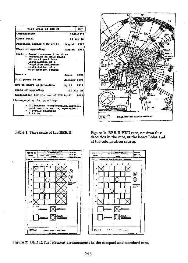
Ti«-Scale of BER II I HKI
Construction 1969-197
Costa total 12 Hio CM
Operation period 5 MM until August 1985
Start of upgrading; August 1985
Goals - Jowtr increase 5 to 10 W- Reduction of grid plat*
SO to 42 positions- installation of aberylliun reflector
- installation of acold neutron source
Restart April 1 9 9 1
Full power 10 MR January 1992
End of start-up procedure April 1992
Costs of upgrading ISO Kio DM
Ipplication for the use of LEO April 1992
Kccompanyinq the upgrading:
- 3 licences (constraction,install,cold neutron source, operation)
- 2 public hearings3 suits
B E R "II SHUHUOW- urn BETEOOUKOMWIIG
Table 1: Time scale of the BER II Figure 1: BER II HEU core, neutron fluxdensities in the core, at the beam holes andat the cold neutron source.
BER-II
Figure 2: BER II, fuel element arrangements in the compact and standard core.
295
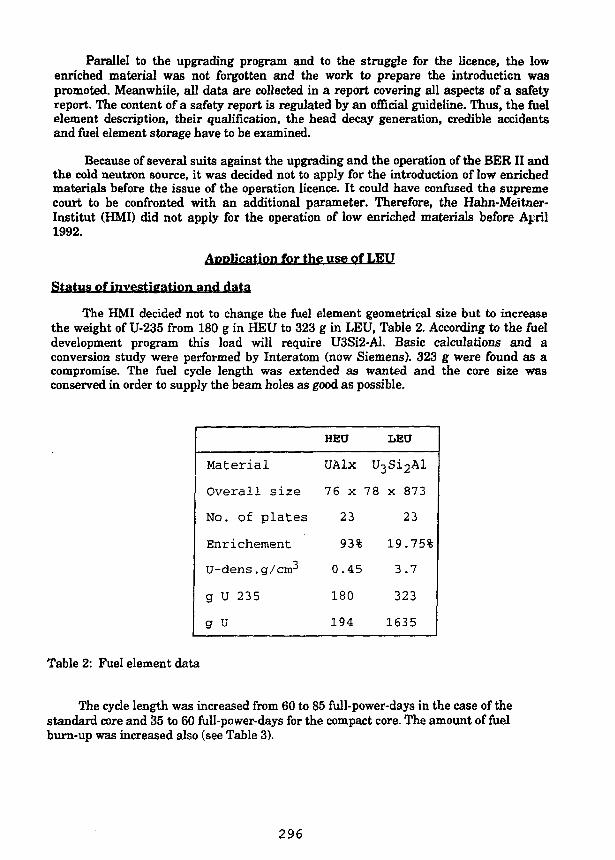
Parallel to the upgrading program and to the struggle for the licence, the lowenriched material was not forgotten and the work to prepare the introduction waspromoted. Meanwhile, all data are collected in a report covering all aspects of a safetyreport. The content of a safety report is regulated by an official guideline. Thus, the fuelelement description, their qualification, the head decay generation, credible accidentsand fuel element storage have to be examined.
Because of several suits against the upgrading and the operation of the BERII andthe cold neutron source, it was decided not to apply for the introduction of low enrichedmaterials before the issue of the operation licence. It could have confused the supremecourt to be confronted with an additional parameter. Therefore, the Hahn-Meitner-Institut (HMD did not apply for the operation of low enriched materials before April1992.
Application for the use of LEU
Status of investigation and data
The HMI decided not to change the fuel element geometrical size but to increasethe weight of U-235 from 180 g in HEU to 323 g in LEU, Table 2. According to the fueldevelopment program this load will require U3SI2-A1. Basic calculations and aconversion study were performed by Interatom (now Siemens). 323 g were found as acompromise. The fuel cycle length was extended as wanted and the core size wasconserved in order to supply the beam holes as good as possible.
Material
Overall size
No. of plates
Enrichement
U-dens . g/cirr
g U 235
g U
HEU
UAlx
76 x
23
93%
0.45
180
194
LEU
U3Si2Al
78 x 873
23
19.75%
3.7
323
1635
Table 2: Fuel element data
The cycle length was increased from 60 to 85 full-power-days in the case of thestandard core and 35 to 60 full-power-days for the compact core. The amount of fuelburn-up was increased also (see Table 3).
296
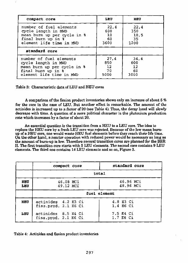
compact core
number of fuel elementscycle length in MWDmean burn up per cycle in %final burn up in %element life time in MWD
standard core
number of fuel elementscycle length in MWDmean burn up per cycle in %final burn up in %element life time in MWD
LEU
22,46001060
3600
27,48501270
5000
HEU
22,435010,535
1200
34,46001260
3000
Table 3: Characteristic data of LEU and HEU cores
A comparison of the fission product inventories shows only an increase of about 5 %for the core in the case of LEU. But another effect is remarkable. The amount of theactinides is increased up to a factor of 20 (see Table 4). Thus, the decay head will slowlydecrease with time. A question of a more political character is the plutonium productionrate which increases by a factor of about 20.
An essential question is the transition from a HEU to a LEU core. The idea toreplace the HEU core by a fresh LEU core was rejected. Because of the low mean burn-up of a HEU core, one would waste HEU fuel elements before they reach their life time.On the other hand, a reactor operation with reduced power would be necessary as long asthe amount of burn-up is low. Therefore several transition cores are planned for the BERII. The first transition core starts with 5 LEU elements. The second core contains 9 LEUelements. The third one contains 14 LEU elements and so on, Figure 3.
HEULEU
HEU
LEU
compact core standard core
total
46.08 MCi49.12 MCI
46.96 MCi48.96 MCi
fuel element
actinides 4.2 E3 Cifiss.prod. 2.1 E6 Ci
actinides 8.5 E4 Cifiss.prod. 2.1 E6 Ci
4.8 E3 Ci1,4 E6 Ci
7.5 E4 Ci1.7 E6 Ci
Table 4: Actinides and fission product inventories
297
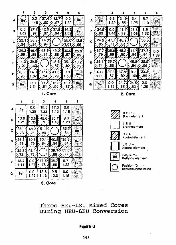
A
B
C
0
E
F
G
1
Be
0.01.49
y " ' *,25.1 •>.94
'26.2'k .99 ,> " * •
14.2'
' i 3 #..98 .
Be
2
0.01.46
27.2.97
s, /•
36.9.94
46.4.88
29.51.03
14.91.02
0.01.34
3
'27.J4>.90
'42 .6 '• .87,,
>,-94;:48.9'' , . 9 1 ,
O>37#^.94/
'30.2/^ . 8 i ;
4
•13.7<
/37.'9i/ •94 '
o>,8s;
^.87/
'4'1'i/
','?*>. . 9 4 '
' j , , y . '
5
0.01.32
14.21.02y, f
26.01.01
30.0.97
36.1. 8 2 .
0.01.50
13.1^".87 ;
6
•••';?&?&":¥Be-:.:
Be
/>?5;
'25.6-^.85,/ " ',13.2'
^ ;
Be
Be
A
B
C
0
E
F
G
1
Be
' 24 '5 '£,-82,
^•85 \
'2>7.Y<<,.T* ;
^36.i''J-.74;
0.01.29
Be
2
9.61.22
0.01.44
47.7,.71
38.9.89
39.7.88
A r S
27.3.87
0.01.31
3
'24.9^
:4iJ.f<
v s s ;
;48.9<> . 8 4 '; 48.2^' , . 9 0 ;
OX37.£^' .92/
* ' f *
'.21.Y,
'',??>
4
9.41.26
26.81.03
C\41.7.84
45.8.84
9.71.50
24.V.83 '
s8.711.3
8.51,32
. 35.8^
v r9 ? ;
'37.8'' , . 84 ;
^25.9^
'z'z'.i'' .89/
* ' f *0.01.28
6
Se
Be
Be
0.01.39
Be
Be
Be
1. Core 2. Core
A
B
c
p
E
F
G
1
Be
10.81.21
f36.'i'^ . 7 3 •
'36.3'
35.9'^.72 '
18.41.11
-Be";''
2
0.01.29
10.51.35
48.2.71
50.5.75
49.4.73
0.01.37
0.01.22
3
18.81.22
•45.6'
>.8O '/. , /
'• 5Q.Y<
O/47.8"'^ .78 /
18.61.16
4
17.31.15
20.71.43
Q40.8.94
39.V.89
38.7.80
9.512.0
5
0.01.18
9.31.23
'35'.2^• •84 '
^ . 8 4 ;
'35.6/' . 77 ;
9.71.22
0.01.15
6
Be
Be
Be
Be
Be
Be
Be
•Be;
o
H E U -Brennelement
L E UBrennelement
H S UKontrollelernent
L E U -KontroIIelement
Beryllium-Reflektorelement
Position furBestrahlungseinsatz
3. Core
Three HEU-LEU Mixed CoresDuring HEU-LEU Conversion
Figure 3
298
After the life time of the transition cores, enough fuel elements of different amounts ofburn-up are produced to enable an arrangement of a LEU core for full power operation.
The mixed HEU-LEU cores seem to be a very economic solution. But questionsarise concerning the power density distributions. One finds jumps in the power densityfactors from HEU elements to the neighboring LEU elements because of the difference inthe U-235 content. However, this has to be checked very carefully, also for the case of afaulty control rod drive. Each deviation of a control rod from the mean average positionof the other rods would increase the difference in the power density factors. Limits haveto be evaluated, otherwise the power has to be reduced.
The report describing the operation of a standard and a compact LEU core iscompleted and represented to the licencing authority. But some questions concerning theoperation of a mixed HEU-LEU core under steady-state and transient conditions have tobe investigated in more detail.
Licencing procedure
The local authority is already in contact with their technical advisor "TechnicalSupervisory Association" (TuV) to verify the safety report and the "Nuclear SafetyOrganisation" (GRS) for questions concerning the safeguards. Then she has to decidewhether to issue the licence directly or to ask the public for comments which will bediscussed at a public hearing. The scale for such a decision is the amount of gain inreactor safety mainly. There is no question that the introduction of LEU would notreduce the reactor safety. In the case of the BER II the amount of the weight of total U-235 is limited to a certain value which corresponds to the number of storage places. Nowfor LEU this value has to be increased because of the higher uranium load by a factor ofabout 2. It is to be decided by the local authority whether this is within public interest.After the licence has heen issued it is expected that opponents will bring suit against theauthority. The Supreme Court of Administration has then to decide in an acceleratedprocedure first, whether to stop the execution of the licence and in a second action if theissue of the licence is legal.
Licencing problems
In Germany a licence is. issued according to a set of different rules and guidelines.Normally, they are worked out and can be applied only for nuclear power plants. In thecase of research reactors there are always problems to apply those regulations. But thelocal authorities can decide how to interprete the regulations. Essential today is the backend of the fuel cycle for nuclear power plants. But the German authorities feelresponsible to the public to include also the research reactors, concerning' this question.
Since 1988 the US-DOE refuses to take back the fuel which they had supplied andno other facilities are available. For instance AEA and Cogema are not able to reprocessLEU material from the MTR fuel type at the moment. That means that the back end ofthe fuel cycle is open. Under these circumstances the local authority will not agree tostart with the operation of LEU at the BER II.
It is quite of interest to remember the intention of INFCE to reduce the amount ofweapon-grade material in the world. The US-DOE often published their nuclear policy inthe Federal Register to support the intention of INFCE. But the realization of theINFCE conclusion is blocked now by the US-DOE policies by not accepting the fuel fromthe BER II. HEU and LEU materials are both concerned. The back end for the BER II
299
HEU material is not closed either, and the 8ERII cannot introduce LEU for the samereason.
Germany had started its own investigation to close the back end of the fuel cycle bydeveloping a program for a long term interim and final storage of research reactor fuel inGermany without the possibility of reprossessing. But the realisation does not onlydepend on the solution of the technical and financial questions, it depends also on thenecessary licences. As long as this procedure is not settled it will not be accepted as analternative way for the solution of the back end of the LEU fuel cycle.
Time scale
Suppose there would not be any questions concerning the back end of the fuel cycle,then a time scale for the introduction of LEU is of interest. The approval of the technicalconcept by the TUV will be expected by April 1993. If a public hearing cannot be avoided,this would take place in the summer of 1993. The licence could be issued by the end of1993. Without the public hearing the licence could be issued in the summer of 1993.Fresh LEU fuel elements cannot be ordered before the iussue of the licence. The time forfabrication is assumed to be more than 1 year. This sums up to a delivery date late in1994 and the first LEU core test could be in 1995.
But as long as the back end of the fuel cycle is not closed, the licence for theoperation of LEU will not be issued.
Conclusion
The Hahn-Meitner-Institut has not applied for the conversion from HEU to LEUmaterial but for the introduction of an alternative fuel to HEU, which means LEU. If thelicence is issued it will decide later, whether it will use HEU or LEU depending on thesituation on the site of the supply of fuel or the site of the back end of the fuel cycle. TheHahn-Meitner-Institut would follow the INFCE intention but sees no other way tocontinue the reactor operation for the users community as long as Germany depends onunforeseen foreign interests.
300
GREEK RESEARCH REACTOR PERFORMANCE CHARACTERISTICS AFTERADDITION OF BERYLLIUM REFLECTOR AND LEU FUEL ,
by
J. R. Deen and James L. Snelgrove
Argonne National LaboratoryArgonne, Illinois, USA
and
C. Papastergiou
National Center for Scientific ResearchAthens, Greece
ABSTRACT
The GRR-1 is a 5-MW pool-type, light-water-moderated and-cooled reactorfueled with MTR-type fuel elements. Recently received Be reflector blockswill soon be added to the core to add additional reactivity until fresh LEU fuelarrives. REBUS-3 xy fuel cycle analyses, using burnup dependent crosssections, were performed to assist in fuel management decisions for the water-and Be-reflected HEU nonequilibrium cores. Cross sections generated byEPRI-CELL have been benchmarked to identical VIM Monte Carlo models.The size of the Be-reflected LEU core has been reduced to 30 elementscompared to 35 for the HEU water-reflected core, and an equilibrium cyclecalculation has been performed.
INTRODUCTION
The Reduced Enrichment Research and Test Reactor (RERTR) Program and the NationalCenter for Scientific Research "Demokritos" initiated a new joint study program in 1991 toinvestigate the conversion of the Greek Research Reactor (GRR-1) from HEU to LEU fuel.This study is a continuation of a previous joint study1 completed in 1981. This paper presentsthe results of modeling the current HEU core operations and the core changes expected uponadding a new Be reflector on two core faces. Since LEU fuel is not expected before August1993 and fresh HEU fuel supplies are very low, some attention is being devoted to fuel cyclestrategies to increase the lifetime of the Be-reflected HEU core. One equilibrium Be-reflectedLEU core design will be presented that has fuel cycle characteristics similar to the currentHEU core. In addition to providing guidance on fuel management strategies, thesepreliminary calculations will provide fuel element loadings for use in analyzing the transitionto an LEU core.
301
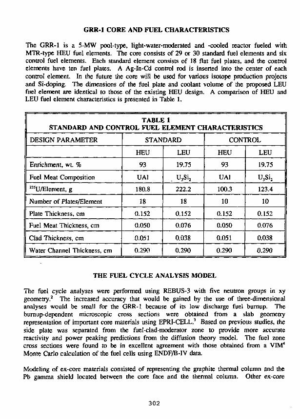
GRR-1 CORE AND FUEL CHARACTERISTICS
The GRR-1 is a 5-MW pool-type, light-water-moderated and -cooled reactor fueled withMTR-type HEU fuel elements. The core consists of 29 or 30 standard fuel elements and sixcontrol fuel elements. Each standard element consists of 18 flat fuel plates, and the controlelements have ten fuel plates. A Ag-In-Cd control rod is inserted into the center of eachcontrol element. In the future the core will be used for various isotope production projectsand Si-doping. The dimensions of the fuel plate and coolant volume of die proposed LEUfuel element are identical to those of the existing HEU design. A comparison of HEU andLEU fuel element characteristics is presented in Table 1.
TABLE 1STANDARD AND CONTROL FUEL ELEMENT CHARACTERISTICS
DESIGN PARAMETER
Enrichment, wt. %
Fuel Meat Composition235U/EIement, g
Number of Plates/Element
Plate Thickness, cm
Fuel Meat Thickness, cm
Clad Thickness, cm
Water Channel Thickness, cm
STANDARD
HEU
93
UAI
180.8
18
0.152
0.050
0.051
0.290
LEU
19.75
. U3Si2
222.2
18
0.152
0.076
0.038
0.290
CONTROL
HEU
93
UAI
100.3
10
0.152
0.050
0.051
0.290
LEU
19.75
U3Si2
123.4
10
0.152
0.076
0.038
0.290
THE FUEL CYCLE ANALYSIS MODEL
The fuel cycle analyses were performed using REBUS-3 with five neutron groups in xygeometry.2 The increased accuracy that would be gained by the use of three-dimensionalanalyses would be small for the GRR-1 because of its low discharge fuel burnup. Theburnup-dependent microscopic cross sections were obtained from a slab geometryrepresentation of important core materials using EPRI-CELL.3 Based on previous studies, theside plate was separated from the fuel-clad-moderator zone to provide more accuratereactivity and power peaking predictions from the diffusion theory model. The fuel zonecross sections were found to be in excellent agreement with those obtained from a VIM4
Monte Carlo calculation of the fuel cells using ENDF/B-IV data.
Modeling of ex-core materials consisted of representing the graphite thermal column and thePb gamma shield located between the core face and the thermal column. Other ex-core
302
features, including experiments, beam tubes, and irradiation rigs, were omitted from thismodel because of insufficient information. We believe this simplified model is sufficientlyaccurate for this stage of the study.
An estimate of the reactivity bias of the fuel cycle model was obtained from an xyz diffusiontheory model of an all-fresh GRR-1 startup core configuration 4B-2. With control rods attheir critical positions, k^ was calculated to be 1.010. This overprediction in reactivity isprobably caused by inaccuracies in radial and axial ex-core material descriptions as well as bythe diffusion model itself. This reactivity bias has been adopted for all fuel cycle analyses.The extrapolation distances for the planar fuel cycle model were obtained from this fresh fuelstartup core calculation.
ANALYSES OF THE HEU WATER-REFLECTED CORE
235U loadings for each element in core and in the storage pools were provided by the GRR-1staff and used to model the actual HEU core fuel cycle beginning on October 26, 1990. Thecore consisted of 29 HEU standard elements and six control elements arranged as shown inFig. 1. The GRR-1 235U loadings were used in conjunction with an EPRI-CELL depletionmodel of the standard and control elements to obtain a complete set of fuel isotopics for eachelement in the core.
The operation of the October 26, 1990 core was followed for 6.66 fpd, after which a freshfuel element was added and the highest burnup fuel element was discharged. This refueledcore was depleted for an additional 22.61 fpd and shut down on May 31, 1991. At this pointa spent fuel element was added to the core in position D-6 without discharging any fuel. Thisincreased the core size to 30 standard elements and six control elements and the 23SU coreloading by 126 g. This core configuration has remained unchanged to date. The currentoperation schedule has been significantly reduced due to the shortage of additional HEU fuelsupplies.
The typical operation schedule for a week at the GRR-1 consists of full-power operation forfive to six hours per week day; the reactor is shut down at all other times. From the exactshutdown and operation intervals, the core excess reactivity was calculated for June 3-7, 1991using the REBUS fuel cycle model. The calculated core reactivities at the beginning and endof each irradiation day are compared to hypothetical equilibrium steady-state operation overthe same period in Fig. 2. On Monday morning, with 135Xe at its lowest level of the week,the core k ^ = 1.066. At the end of the day, the core reactivity has fallen to k = 1.060 due tothe buildup of l35Xe. For the remainder of the week, the core reactivity increases during theday due to the burnout of 135Xe accumulated during the preceding night's shutdown period.During the week the startup excess reactivity decreases each day except Friday, when a slightincrease in excess reactivity has been observed at the GRR-1 and predicted using this model.From these results, shown in Fig. 3, one can also note that the GRR-1 never reachesequilibrium I35Xe. The l49Sm concentration changes very little and remains betweensaturation and equilibrium values during the entire week, as shown in Fig. 4. This operationschedule, with short irradiation intervals and relatively long shutdown periods, maintainspoison concentrations low enough to provide the excess reactivity required for continued operation.
303
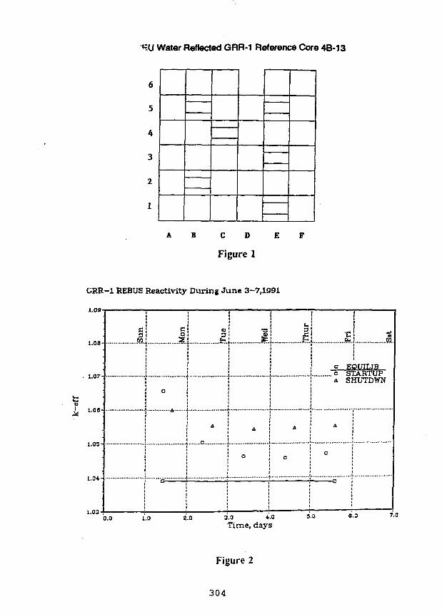
«=U Water Reflected GRR-1 Reference Core 4B-13
6
5
4
3
2
1
A B CD E F
Figure 1
GRR-l REBUS Reactivity During June 3-7,1991
1.091
1.Q8-
• t.07
5I 1-08-
i.OS-
1.0+-
1.03-1
...I.
o EOUILIB. c STARTUP& SHUTDWN
o.o i.o 2.0 3.0 4.0Time, days
s.a 6.3 r.a
Figure 2
304
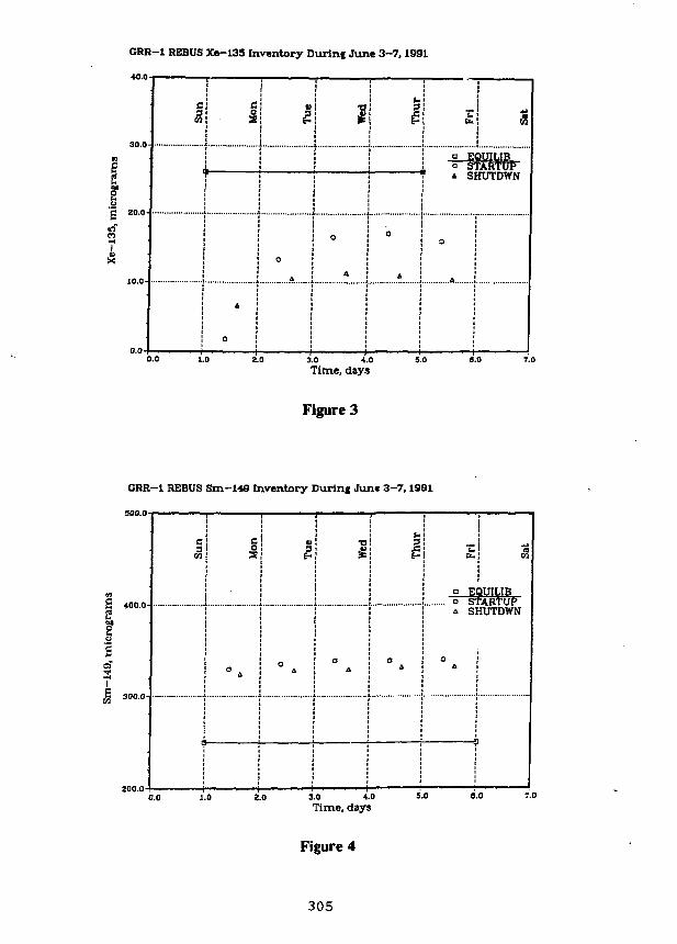
GRR-1 REBUS Xe-135 Inventory Durinf June 3-7,1991
30.0
20.0-
10.0'
I Mon
A ;
° !' • • • i
Tue
o
A j
Wed
o
A ;
. . . . )
1 1
0
A i
j j
bi m\
a EOUILIBo STARTUP
1 A SHUTDWN
o
A
0.0 1.0 3.0 4.0
Time, days
Figure 3
GRR-l REBUS Sm-148 Inventory During June 3-7,1991
400.0
300.0-
Su
n
! O
Tue
oA
Wed
oA
Thu
r
oA
! £
a E
Sat
3UILIBo S-rAHTUPA SHUTDWN
° A
CO 1.0 3.0 4.0
Time, daysS.O 8.0
Figure 4
305
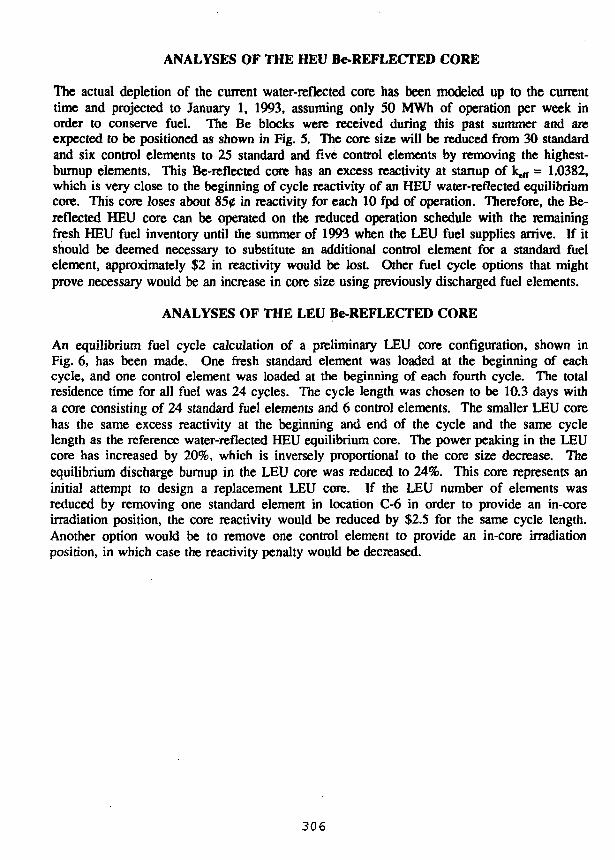
ANALYSES OF THE HEU Be-REFLECTED CORE
The actual depletion of the current water-reflected core has been modeled up to the currenttime and projected to January 1, 1993, assuming only 50 MWh of operation per week inorder to conserve fuel. The Be blocks were received during this past summer and areexpected to be positioned as shown in Fig. 5. The core size will be reduced from 30 standardand six control elements to 25 standard and five control elements by removing the highest-burnup elements. This Be-reflected core has an excess reactivity at startup of ke(T = 1.0382,which is very close to the beginning of cycle reactivity of an HEU water-reflected equilibriumcore. This core loses about 850 in reactivity for each 10 fpd of operation. Therefore, the Be-reflected HEU core can be operated on the reduced operation schedule with the remainingfresh HEU fuel inventory until the summer of 1993 when the LEU fuel supplies arrive. If itshould be deemed necessary to substitute an additional control element for a standard fuelelement, approximately $2 in reactivity would be lost. Other fuel cycle options that mightprove necessary would be an increase in core size using previously discharged fuel elements.
ANALYSES OF THE LEU Be-REFLECTED CORE
An equilibrium fuel cycle calculation of a preliminary LEU core configuration, shown inFig. 6, has been made. One fresh standard element was loaded at the beginning of eachcycle, and one control element was loaded at the beginning of each fourth cycle. The totalresidence time for all fuel was 24 cycles. The cycle length was chosen to be 10.3 days witha core consisting of 24 standard fuel elements and 6 control elements. The smaller LEU corehas the same excess reactivity at the beginning and end of the cycle and the same cyclelength as the reference water-reflected HEU equilibrium core. The power peaking in the LEUcore has increased by 20%, which is inversely proportional to the core size decrease. Theequilibrium discharge burnup in the LEU core was reduced to 24%. This core represents aninitial attempt to design a replacement LEU core. If the LEU number of elements wasreduced by removing one standard element in location C-6 in order to provide an in-coreirradiation position, the core reactivity would be reduced by $2.5 for the same cycle length.Another option would be to remove one control element to provide an in-core irradiationposition, in which case the reactivity penalty would be decreased.
306
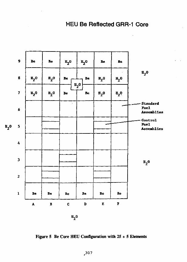
HEU Be Reflected GRR-1 Core
Be
H20
H20
Be
Be
V
=2°
Be
H20
Be
H20
VBe
Be
Be
Be
Be
H20
H2°
—
Be
Be
H20
H2Q
.
Be
H20
- StandardFuelAssemblies
FuelAssemblies
H20
Figure 5 Be Core HEU Configuration with 25 + 5 Elements
307
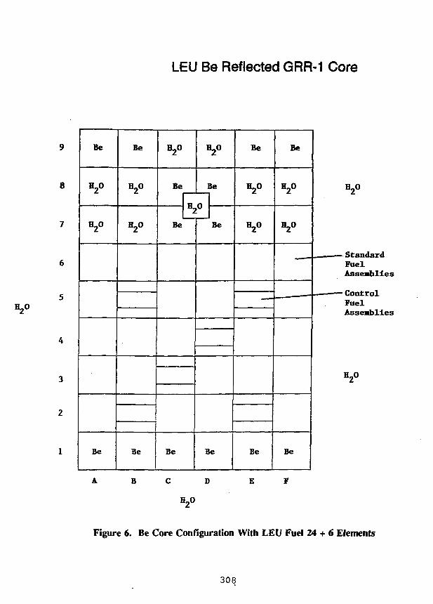
LEU Be Reflected GRR-1 Core
Be
H2O
H2°
Be
Be
H2O
H20
Be
H2°
Be
H2O
Be
n2°Be
Be
Be
Be
Be
H20
H2°
——•
Be
Be
H20
H2O
_
Be
E
StandardFuelAssemblies
• ControlFuelAssemblies
Figure 6. Be Core Configuration With LEU Fuel 24 + 6 Elements
308
Locations of experimental facilities will significantly affect the final core configuration. Thereactivity performance could be increased without a change in core size by replacing onecontrol element with a standard element if the core can be adequately controlled using fivecontrol elements.
CONCLUSIONS
The GRR-1 has had to significantly reduce its operation schedule caused by a shortage offresh HEU fuel. Once all the necessary preparations for installation of the Be reflector forthe HEU core have been completed, additional reactivity can be added to extend the corelifetime until LEU fuel arrives next summer. The use of the reactor for isotope productionand Si-doping will significantly affect the final decision regarding the most suitable LEU coreconfiguration. The issues of transition from HEU to equilibrium LEU cores by the additionof one element per cycle must also be addressed.
REFERENCES
1. C. Papastergiou and J. Deen, "Neutronic Calculations for the Conversion of the GRR-1Reactor from HEU Fuel to LEU Fuel," unpublished ANL report, (November, 1981).
2. B. J. Toppel, "A User's Guide for the REBUS-3 Fuel Cycle Analysis Capability,"ANL-83-2, (March, 1983).
3. B. A. Zolotar, et al., "EPRI-CELL Code Description," Advanced Recycle MethodologyProgram System Documentation,", Part II, Chapter 5, (September, 1997).
4. R. N. Blomquist, "VIM - A Continuous Energy Neutronics and Photon TransportCode," pp. 222 - 224, ANS Proceedings of the Topical Meeting on Advances inReactor Computations, Salt Lake City, Utah, (March 28-31 , 1983).
309
S E S S I O N IX
October 1, 1992
UTILIZATION OF CONVERTED REACTORS
Chairman:
J.W. Schreader(AECL Research, Canada)
311
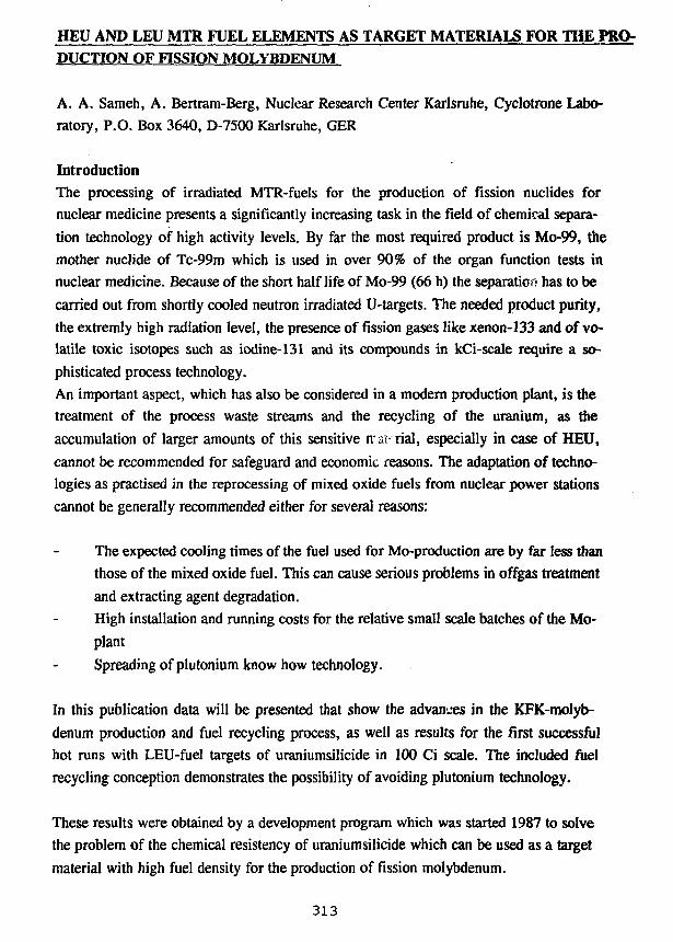
HEU AND LEU MTR FUEL ELEMENTS AS TARGET MATERIALS FOR THE PRO-DUCTION OF FISSION MOLYBDENUM
A. A. Sameh, A. Bertram-Berg, Nuclear Research Center Karlsruhe, Cyclotrone Labo-
ratory, P.O. Box 3640, D-7500 Karlsruhe, GER
IntroductionThe processing of irradiated MTR-fuels for the production of fission nuclides for
nuclear medicine presents a significantly increasing task in the field of chemical separa-
tion technology of high activity levels. By far the most required product is Mo-99, the
mother nuclide of Tc-99m which is used in over 90% of the organ function tests in
nuclear medicine. Because of the short half life of Mo-99 (66 h) the separation has to be
carried out from shortly cooled neutron irradiated U-targets. The needed product purity,
the extremly high radiation level, the presence of fission gases like xenon-133 and of vo-
latile toxic isotopes such as iodine-131 and its compounds in kCi-scale require a so-
phisticated process technology.
An important aspect, which has also be considered in a modern production plant, is the
treatment of the process waste streams and the recycling of the uranium, as the
accumulation of larger amounts of this sensitive ira'c rial, especially in case of HEU,
cannot be recommended for safeguard and economic reasons. The adaptation of techno-
logies as practised in the reprocessing of mixed oxide fuels from nuclear power stations
cannot be generally recommended either for several reasons:
The expected cooling times of the fuel used for Mo-production are by far less than
those of the mixed oxide fuel. This can cause serious problems in offgas treatment
and extracting agent degradation.
High installation and running costs for the relative small scale batches of the Mo-
plant
Spreading of plutonium know how technology.
In this publication data will be presented that show the advances in the KFK-molyb-
denum production and fuel recycling process, as well as results for the first successful
hot runs with LEU-fuel targets of uraniumsilicide in 100 Ci scale. The included fuel
recycling conception demonstrates the possibility of avoiding plutonium technology.
These results were obtained by a development program which was started 1987 to solve
the problem of the chemical resistency of uraniumsilicide which can be used as a target
material with high fuel density for the production of fission molybdenum.
313
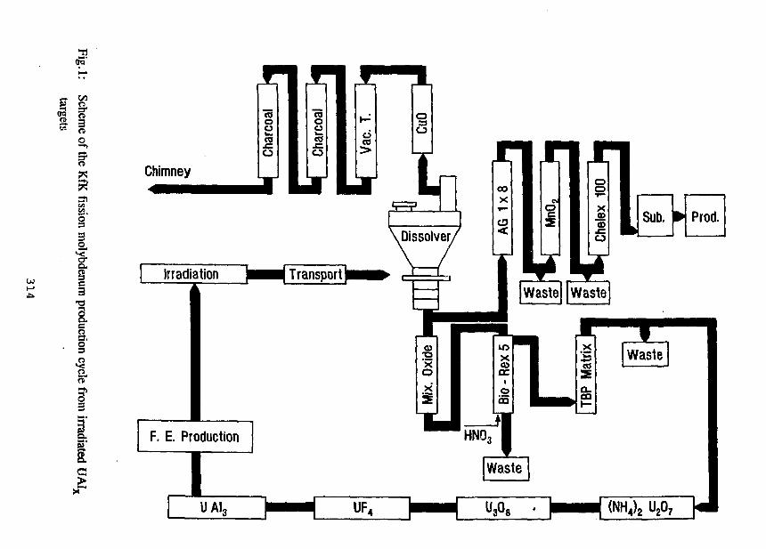
oS"
nO
§
2,
§
i1
ft"
I
I
The achievement of this aim would allow the replacement of HEU by LEU in the Mo-production. An important aspect which had to be taken into account, was, that allmodifications in the process could be adopted economically and without significantchanges in the installation hard wear for the existing KfK production cycle from UA1X
targets [1], as shown in figure 1.
Another aim of this program was the development and demonstration of an efficientchromatographic system for the selective separation and purification of iodine from theacidic streams of the molybdenum production process. The realization of this aim wouldhave two benefits, higher process economy due to optimizations in the waste treatmentcosts and additional income from iodine-131 selling.
Production cycle of fission molybdenum
Preparation of the uraniumsilkide alloyThe uraniumsilicide was produced by melting uranium and silicon metal together at
1850°C in an argon gas atmosphere.
According to realistic production conditions the U-metal preparation had to be started
from U3Og generated from the calcination of yellowcake, which presents the last chemi-
cal step of the uranium purification process.
The uranium oxide was transfered to a nickel crucible and converted to the tetrafluoride
by treatment with a gas mixture of hydrogen and hydrogenfluoride in an argon gas at-
mosphere at 650°C. The reaction was carried out in a nickel oven. The UF^-powder was
then converted to KUF5 by melting the tetrafluoride with the stochiometric amount of
potassiumfluoride in the same oven at 850°C. Due to the high chemical reactivity of this
system, the conversion to KUF5 was carried out in a graphite crucible. The product was
powdered and added in small portions to a melting electrolyses bath containing a salt
mixture of 50 weight % NaCl and CaC^, in which the graphite crucible was the anode. A
molybdenum sheet was used as the cathode. The process was carried out in an argon gas
atmosphere at 800°C. After the electrolysis the uranium carrying cathode was washed in
an ultrasonic bath subsequently with ethylalcohol containing few percents of water and
cold water to dissolve the salts accompanying the uranium. The dried U-powder was fi-
nally melted with silicon to 1̂ 3812.
Production and irradiation of the MTR-fuel target
The alloy was transfered into a glove box line in which the UoSi^ was grinded in a hard
metall swinging mill. Only particles with grain sizes below 40 micro meters were mixed
with aluminium powder of the same particle size. Aliquots of this mixture were pressed
315
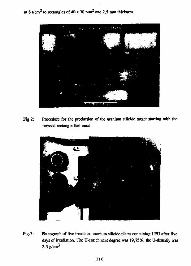
at 8 t/cm2 to rectangles of 40 x 30 mm^ and 2.5 mm thickness.
Fig.2: Procedure for the production of the uranium silicide target starting with the
pressed rectangle fuel meat
Fig.3: Photograph of five irradiated uranium silicide plates containing LEU after five
days of irradiation. The U-enrichment degree was 19,75%, the U-densitiy was
2.3 g/cm3
316
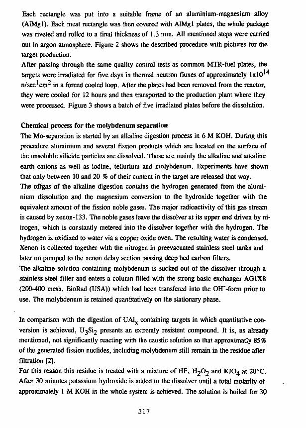
Each rectangle was put into a suitable frame of an aluminium-magnesium alloy(AIMgl). Each meat rectangle was then covered with AlMgl plates, the whole packagewas riveted and rolled to a final thickness of 1.3 mm. All mentioned steps were carriedout in argon atmosphere. Figure 2 shows the described procedure with pictures for thetarget production.
After passing through the same quality control tests as common MTR-fuel plates, thetargets were irradiated for five days in thermal neutron fluxes of approximately lxlO14
n/sec^cm^ in a forced cooled loop. After the plates had been removed from the reactor,they were cooled for 12 hours and then transported to the production plant where theywere processed. Figure 3 shows a batch of five irradiated plates before the dissolution.
Chemical process for the molybdenum separation
The Mo-separation is started by an alkaline digestion process in 6 M KOH. During this
procedure aluminium and several fission products which are located on the surface of
the unsoluble silicide particles are dissolved. These are mainly the alkaline and alkaline
earth cations as well as iodine, tellurium and molybdenum. Experiments have shown
that only between 10 and 20 % of their content in the target are released that way.
The offgas of the alkaline digestion contains the hydrogen generated from the alumi-
nium dissolution and the magnesium conversion to the hydroxide together with the
equivalent amount of the fission noble gases. The major radioactivity of this gas stream
is caused by xenon-133. The noble gases leave the dissolver at its upper end driven by ni-
trogen, which is constantly metered into the dissolver together with the hydrogen. The
hydrogen is oxidized to water via a copper oxide oven. The resulting water is condensed.
Xenon is collected together with the nitrogen in preevacuated stainless steel tanks and
later on pumped to the xenon delay section passing deep bed carbon filters.
The alkaline solution containing molybdenum is sucked out of the dissolver through a
stainless steel filter and enters a column filled with the strong basic exchanger AG1X8
(200-400 mesh, BioRad (USA)) which had been transfered into the OH'-form prior to
use. The molybdenum is retained quantitatively on the stationary phase.
In comparison with the digestion of UA1X containing targets in which quantitative con-
version is achieved, U3Si2 presents an extremly resistent compound. It is, as already
mentioned, not significantly reacting with the caustic solution so that approximatly 85%
of the generated fission nuclides, including molybdenum still remain in the residue after
filtration [2].
For this reason this residue is treated with a mixture of HF, ^Oj and KJO4 at 20°C.
After 30 minutes potassium hydroxide is added to the dissolver until a total molarity of
approximately 1 M KOH in the whole system is achieved. The solution is boiled for 30
317
minutes to drive out the H2O2 and then cooled to a temperature of 40 °C. This alkalinesolution now contains all the molybdenum and the same fission nuclide impurities as inthe case of the alkaline digestion solution only in higher content.
The atiack of the silicide presented the main task of the investigations. They led to thede elopment of a new process [3] which permits an efficient and quick chemical conver-sion of the uranium silicide, so that the previously in the crystals of the alloy enclosedfission nuclides are released. It will be described in more detail in the following part ofthe publication. The description of the whole Mo-production process will be continuedafterwards.
Catalytic conversion of the uraniumsilicide alloy
The chemical principle of the newly developed dissolution system which consists of a
mixture of HF, H2O2, KJ is based on the catalytic oxidation of the uranium to UF4 by
the reaction between the silicide and hydrogen fluoride. Uranium tetrafluoride is for-
ming an unsoluble layer wrapping the uranium silicide particles and prevents, together
with the generated hydrogen bubbles, the penetration of HF to the alloy. Beside this, the
generated hydrogen bubbles hinder the H2O2 to oxidize the U"*" to U + " before its de-
composition on the surface of the fine residue. Only the presence of iodine eliminates
these drawbacks. The hydrogen generated during dissolution is oxidized by the iodine.
The formed iodide is immidiately oxidized back by the H2O2 to J2, which is again oxidi-
zing the U to U . The use of iodine compounds in higher oxidation states such as
KJO4 accelerate in the beginning the uranium oxidation and its conversion. The opti-
mum process conditions were determined in several experiments in which relevant pa-
rameters such as the contact time between the solid and aqueous phase, the H2O2, the
HF, and the catalysator concentrations were varied.
The determination of the conversion yields was carried out in the following way. At the
end of each experiment the reaction was stopped by adding a surplus amount of KOH
solution to the system. The liquid phase was separated by centrifugation. The residue
was washed several times with diluted KOH and the liquid phase separated as above
mentioned. At last the residue was treated with boiling 3 M HNO3 for few minutes,
which dissolved the formed diuranate precipitate immidiately. The dissolved uranium
amount is identical with the converted silicide amount. The uranium concentration was
determined via spectral photometry and the converted uranium amount by comparing
the uranium amounts before and after treatment with the oxidizing HF mixture. The
presence of a dark residue was a clear hint for unconverted silicide crystals. Figure 4
shows the influence of the potassium periodate concentration in the HF/H2O2 mixture
on the uranium conversion after the treatment of the silicide residue.
318
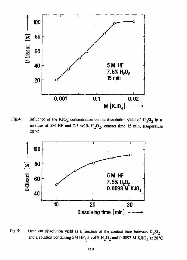
0.001 0.1 0.02M [KJ04]
Fig.4: Influence of the KJO4 concentration on the dissolution yield of U3Si2 in amixture of 5M HF and 7.5 vol% H2O2, contact time 15 min, temperature20°C
20 30Dissolving time [min] —
Fig.5: Uranium dissolution yield as a function of the contact time between U3S12
and a solution containing 5M HF, 5 vol% H2O2 and 0.0093 M KJIO4 at 20°C
319
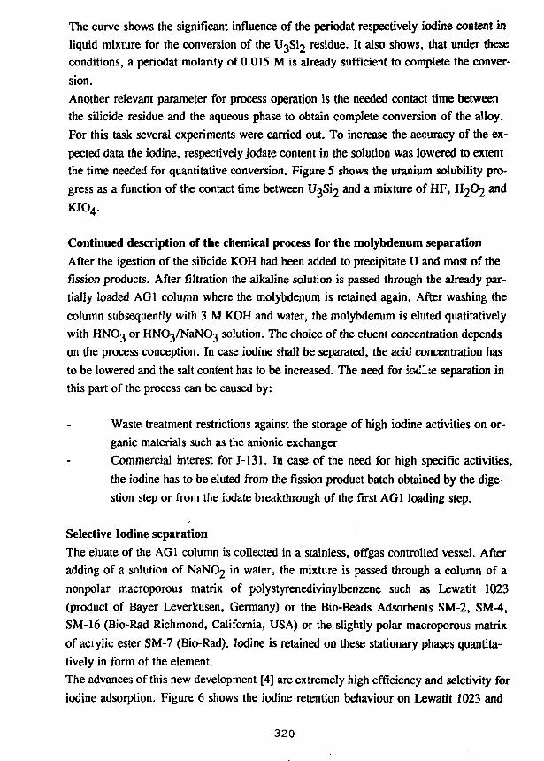
The curve shows the significant influence of the periodat respectively iodine content in
liquid mixture for the conversion of the U3S12 residue. It also shows, that under these
conditions, a periodat molarity of 0.0 IS M is already sufficient to complete the conver-
sion.
Another relevant parameter for process operation is the needed contact time between
the silicide residue and the aqueous phase to obtain complete conversion of the alloy.
For this task several experiments were carried out. To increase the accuracy of the ex-
pected data the iodine, respectively jodate content in the solution was lowered to extent
the time needed for quantitative conversion. Figure 5 shows the uranium solubility pro-
gress as a function of the contact time between U3S12 and a mixture of HF, H2O2 and
KJO4.
Continued description of the chemical process for the molybdenum separation
After the igestion of the silicide KOH had been added to precipitate U and most of the
fission products. After filtration the alkaline solution is passed through the already par-
tially loaded AG1 column where the molybdenum is retained again. After washing the
column subsequently with 3 M KOH and water, the molybdenum is eluted qualitatively
with HNO3 or HNCtyNaNO^ solution. The choice of the eluent concentration depends
on the process conception. In case iodine shall be separated, the acid concentration has
to be lowered and the salt content has to be increased. The need for iocLie separation in
this part of the process can be caused by:
Waste treatment restrictions against the storage of high iodine activities on or-
ganic materials such as the anionic exchanger
Commercial interest for J-131. In case of the need for high specific activities,
the iodine has to be eluted from the fission product batch obtained by the dige-
stion step or from the iodate breakthrough of the first AG1 loading step.
Selective Iodine separation
The eluate of the AG1 column is collected in a stainless, offgas controlled vessel. After
adding of a solution of NaNC>2 in water, the mixture is passed through a column of a
nonpolar macroporous matrix of polystyrenedivinylbenzene such as Lewatit 1023
(product of Bayer Leverkusen, Germany) or the Bio-Beads Adsorbents SM-2, SM-4,
SM-16 (Bio-Rad Richmond, California, USA) or the slightly polar macroporous matrix
of acrylic ester SM-7 (Bio-Rad). Iodine is retained on these stationary phases quantita-
tively in form of the element.
The advances of this new development [4] are extremely high efficiency and selctivity for
iodine adsorption. Figure 6 shows the iodine retention behaviour on Lewatit 1023 and
320
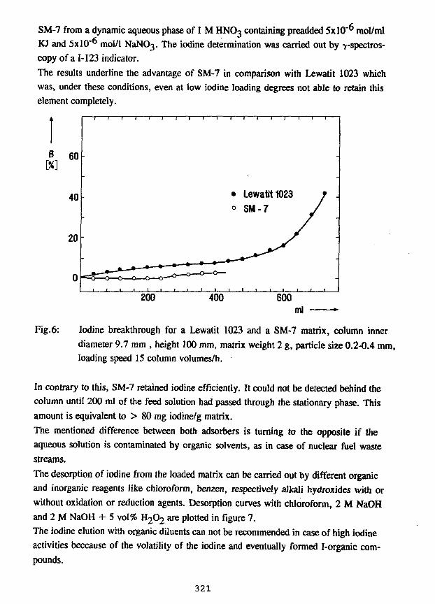
SM-7 from a dynamic aqueous phase of 1 M HNO3 containing preadded 5x10"^ mol/mlKJ and 5x10~6 mol/1 NaNO3. The iodine determination was carried out by 7-spectros-copy of a 1-123 indicator.
The results underline the advantage of SM-7 in comparison with Lewatit 1023 whichwas, under these conditions, even at iow iodine loading degrees not able to retain thiselement completely.
Fig.6: Iodine breakthrough for a Lewatit 1023 and a SM-7 matrix, column innerdiameter 9.7 mm , height 100 mm, matrix weight 2 g, particle size 0.2-0.4 mm,loading speed IS column volumes/h.
In contrary to this, SM-7 retained iodine efficiently. It could not be detected behind thecolumn until 200 ml of the feed solution had passed through the stationary phase. Thisamount is equivalent to > 80 mg iodine/g matrix.
The mentioned difference between both adsorbers is turning to the opposite if theaqueous solution is contaminated by organic solvents, as in case of nuclear fuel wastestreams.
The desorption of iodine from the loaded matrix can be carried out by different organicand inorganic reagents like chloroform, benzen, respectively alkali hydroxides with orwithout oxidation or reduction agents. Desorption curves with chloroform, 2 M NaOHand 2 M NaOH + 5 vol% H2O2 are plotted in figure 7.
The iodine elution with organic diluents can not be recommended in case of high iodineactivities beccause of the volatility of the iodine and eventually formed I-organic com-pounds.
321
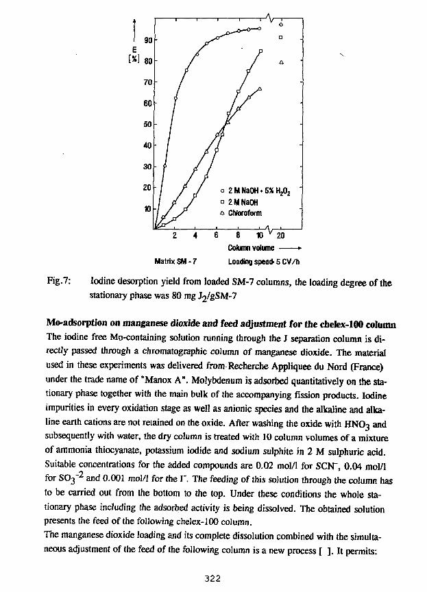
Matrix SM-7
6 8 10 v 20
Column volume •
Loading speed- 5 CV/h
Fig.7: Iodine desorption yield from loaded SM-7 columns, the loading degree of thestationary phase was 80 mg J2/gSM-7
Mo-adsorption on manganese dioxide and feed adjustment for the chelex-100 columnThe iodine free Mo-containing solution running through the J separation column is di-
rectly passed through a chromatographic column of manganese dioxide. The material
used in these experiments was delivered from Recherche Appliquee du Nord (France)
under the trade name of "Manox A". Molybdenum is adsorbed quantitatively on the sta-
tionary phase together with the main bulk of the accompanying fission products. Iodine
impurities in every oxidation stage as well as anionic species and the alkaline and alka-
line earth cations are not retained on the oxide. After washing the oxide with HNOo m<*
subsequently with water, the dry column is treated with 10 column volumes of a mixture
of ammonia thiocyanate, potassium iodide and sodium sulphite in 2 M sulphuric acid.
Suitable concentrations for the added compounds are 0.02 mol/1 for SCN", 0.04 mol/1
for SO3"2 and 0.001 mol/1 for the I". The feeding of this solution through the column has
to be carried out from the bottom to the top. Under these conditions the whole sta-
tionary phase including the adsorbed activity is being dissolved. The obtained solution
presents the feed of the following chelex-100 column.
The manganese dioxide loading and its complete dissolution combined with the simulta-
neous adjustment of the feed of the following column is a new process [ ]. It permits:
322
Quick and lossfree combination of the AG 1 column with the chelex-100 systemwhich guaratees excellent product purities
Efficient reduction of the waste ammount generated under the former conditions[1] in which the Molybdenum was eluted with sulphuric acid and subsequently withammonium hydroxide and sodium sulfate mixtures that had to be adjusted into thesuitable feeding conditions of the chelex column later on.Additional increase of the molybdenum decontamination from the highly radio-toxic nuclides J-131 and Sr-90
Final chrotnatographic purifcation of molybdenum on chelex-100
The solution containing the molybdenum, the dissolved manganese and the accom-
panying fission product impurities are passed through a chelex-100 column. The molyb-
denum is retained quantitatively on the exchanger as [Mo(SCN)g]"^ [6,7], while the
manganese ions and the fission product species are not adsorbed on the column. Chelex-
100 is a styrene divinylbenzene copolymer containing iminodiacetat ions which act as
chelating groups for metal ions. The advantage of chelex-100 for the purification of mo-
lybdenum is based on the capability of the resin to act as anionic or as cationic exchan-
ger in dependence of the pH in the process solution. Under strongly acidic conditions it
is an anionic exchanger which is able to adsorb the negatively charged molybdenum-
rhodano complexes quantitatively, while they are efficiently desorbed from the sta-
tionary phase in strongly basic solutions .
To achieve optimum Mo-retention conditions on chelex the adsorber has to be pretrea-
ted with 2 M sulphuric acid containing approximately the same SCN", SO$^ and I"
amounts as in the feed. The preconditioning has to be done just before the molybdenum
loading.
The column is subsequently washed with sulphuric acid containing thiocyanate, pure
sulphuric acid and water. The molybdenum elutio.i from the column is carried out with 1
M NaOH. To guarantee a product of highest purity the procedure is repeated on a se-
cond smaller chelex-100 column of a particle size range between 100-200 mesh.
A significant difference presents the molybdenum elution from this column. It has to be
carried out with 6 M ammonium hydroxide in consideration for the final process step,
the molybdenum oxide sublimation.
Molybdenum oxide sublimation and product adjustment
The ammonium molybdat eluate is transfered to the sublimation cell. The molybdenum
solution is evaporated to a volume of few milliliters and afterwards placed into a plati-
num crucible. The solution is evaporated on an elecric hot plate and the crucible with
the completely dry residue slowly heated up to about 700°C in a quartz glass apparatus
323
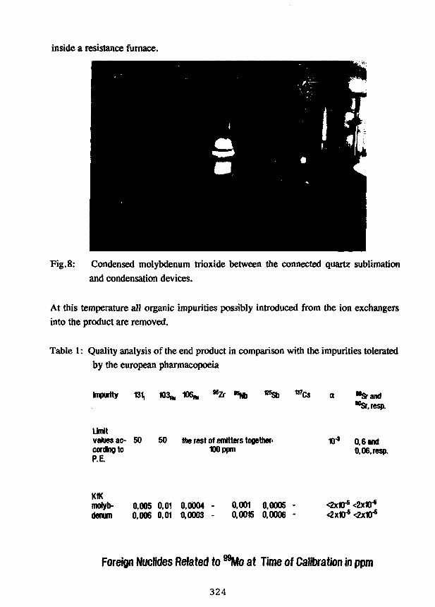
inside a resistance furnace.
Fig.8: Condensed molybdenum trioxide between the connected quartz sublimation
and condensation devices.
At this temperature all organic impurities possibly introduced from the ion exchangersinto the product are removed.
Table 1: Quality analysis of the end product in comparison with the impurities toleratedby the european pharmacopoeia
Impurity 131, 103* 106* *Zr vsSb w Cs a "srand"Sr.resp.
Limitvalues ac- SO 50 the rest of emitters together-cordng to 100 ppmP.E.
0.6 and0,06,resp.
molyb- 0.005 0,01 0,0004 - 0,001 0,0005 - <2xt0fs <2xKT*denum 0,006 0,01 0,0003 - 0.0015 0,0006 - <2xW* <2x1Q-s
Foreign Nuclides Related to "Mo at Time of Calibration in ppm
324
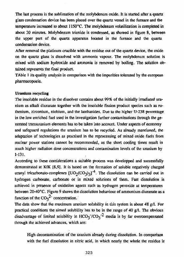
The last process is the sublimation of the molybdenum oxide. It is started after a quartzglass condensation device has been placed over the quartz vessel in the furnace and thetemperature increased to about 1150°C. The molybdenum volatilization is completed inabout 30 minutes. Molybdenum trioxide is condensed, as showed in figure 8, betweenthe upper part of the quartz apparatus located in the furnace and the quartzcondensation device.
After removal the platinum crucible with the residue out of the quartz device, the oxideon the quartz glass is dissolved with ammonia vapour. The molybdenum solution ismixed with sodium hydroxide and ammonia is removed by boiling. The solution ob-tained represents the final product.
TAble 1 its quality analysis in comparison with the impurities tolerated by the europeanpharmacopoeia.
Uranium recyclingThe insoluble residue in the dissolver contains about 99% of the initially irradiated ura-
nium as alkali diuranate together with the insoluble fission product species such as ru-
thenium, zirconium, niobium, and the Ianthanides. Due to the higher U-238 percentage
in the low enriched fuel used in the investigation further contaminations through the ge-
nerated transuranium elements has to be taken into account. Under aspects of economy
and safeguard regulations the uranium has to be recycled. As already mentioned, the
adaptation of technologies as practised in the reprocessing of mixed oxide fuels from
nuclear power stations cannot be recommended, as the short cooling times result in
much higher radiation dose concentrations and contamination levels of the uranium by
1-131.
According to these considerations a suitable process was developped and successfully
demonstrated at KfK [8,9], It is based on the formation of soluble negatively charged
uranyl tricarbonato-complexes [ U C ^ C O ^ ] . The dissolution can be carried out in
hydrogen carbonate, carbonate or in mixed solutions of them. Fast dissolution is
achieved in presence of oxidation agents such as hydrogen peroxide at temperatures
between 20-40°C. Figure 9 shows the dissolution behaviour of ammonium diuranate as a
function of the CC^" concentration.
The data show that the maximum uranium solubility in this system is about 48 g/1. For
practical conditions the aimed solubility has to be in the range of 40 g/1. The obvious
disadvantage of limited solubility in HCO^'ICO^ media is by far overcompensated
through the achieved advances, which are:
High decontamination of the uranium already during dissolution. In comparison
with the fuel dissolution in nitric acid, in which nearly the whole the residue is
325
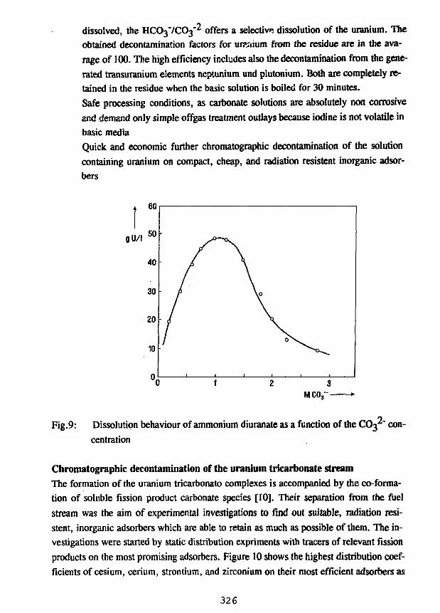
dissolved, the HCO3-/CO3-2 offers a selective dissolution of the uranium. The
obtained decontamination factors for uranium from the residue are in the ava-
rage of 100. The high efficiency includes also the decontamination from the gene-
rated transuranium elements neptunium und plutonium. Both are completely re-
tained in the residue when the basic solution is boiled for 30 minutes.
Safe processing conditions, as carbonate solutions are absolutely non corrosive
and demand only simple offgas treatment outlays because iodine is not volatile in
basic media
Quick and economic further chromatographic decontamination of the solution
containing uranium on compact, cheap, and radiation resistent inorganic adsor-
bers
gU/l
Fig.9: Dissolution behaviour of ammonium diuranate as a function of the COj^" con-
centration
Chromatographic decontamination of the uranium tricarbonate streamThe formation of the uranium tricarbonato complexes is accompanied by the co-forma-
tion of soluble fission product carbonate species [10]. Their separation from the fuel
stream was the aim of experimental investigations to find out suitable, radiation resi-
stent, inorganic adsorbers which are able to retain as much as possible of them. The in-
vestigations were started by static distribution expriments with tracers of relevant fission
products on the most promising adsorbers. Figure 10 shows the highest distribution coef-
ficients of cesium, cerium, strontium, and zirconium on their most efficient adsorbers as
326
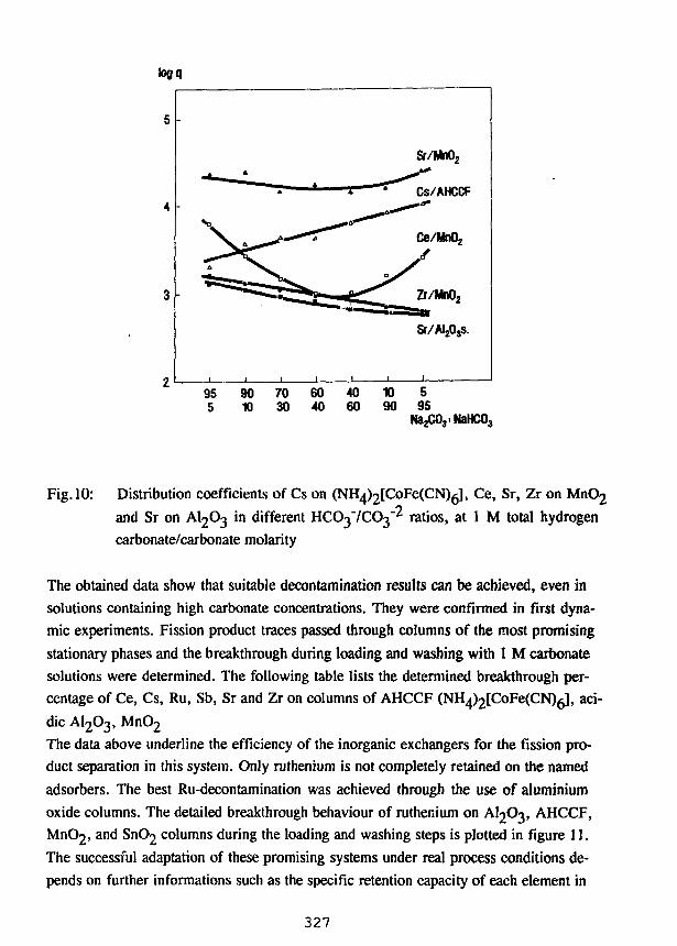
95 90 70 60 405 10 30 40 60
10 590 95
NaHC03
Fig. 10: Distribution coefficients of Cs on (NH^tCoFeCCN)^], Ce, Sr, Zr on MnO2
and Sr on AI2O3 in different HCC^' /CC^ ratios, at 1 M total hydrogen
carbonate/carbonate molarity
The obtained data show that suitable decontamination results can be achieved, even in
solutions containing high carbonate concentrations. They were confirmed in first dyna-
mic experiments. Fission product traces passed through columns of the most promising
stationary phases and the breakthrough during loading and washing with 1 M carbonate
solutions were determined. The following table lists the determined breakthrough per-
centage of Ce, Cs, Ru, Sb, Sr and Zr on columns of AHCCF (NH4)2[CoFe(CN)6L aci-
dic AI2O3, MnO2
The data above underline the efficiency of the inorganic exchangers for the fission pro-
duct separation in this system. Only ruthenium is not completely retained on the named
adsorbers. The best Ru-decontamination was achieved through the use of aluminium
oxide columns. The detailed breakthrough behaviour of ruthenium on AI2O3, AHCCF,
MnC«2, and SnC>2 columns during the loading and washing steps is plotted in figure 11.
The successful adaptation of these promising systems under real process conditions de-
pends on further informations such as the specific retention capacity of each element in
327
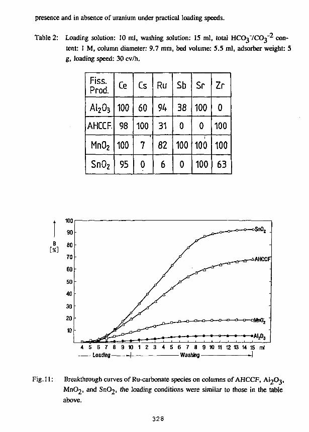
presence and in absence of uranium under practical loading speeds.
Table 2: Loading solution: 10 ml, washing solution: 15 ml, total HCO37CO3"2 con-
tent: 1 M, column diameter: 9.7 mm, bed volume: 5.5 ml, adsorber weight: 5
g, loading speed: 30 cv/h.
Fiss.Prod.
AI2O3
AHCCF.
MnO2
SnO2
Ce
100
98
100
95
Cs
60
100
7
0
Ru
94
31
82
6
Sb
38
0
100
0
Sr
100
0
100
100
Zr
0
100
100
63
[X]
4 5 6 7 8 9 1 0 1 2 3 4 5 6 7 8 9 1 0 11 12 13 14 15 mlLoading H Washing -J
Fig. 11: Breakthrough curves of Ru-carbonate species on columns of AHCCF, AI2O3,
MnC^, and SnOj, the loading conditions were similar to those in the table
above.
328
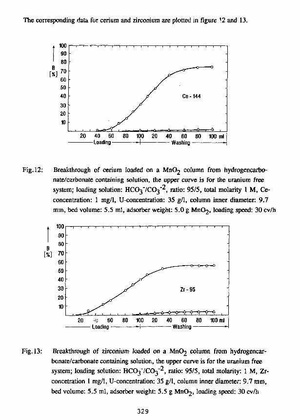
The corresponding data for cerium and zirconium are plotted in figure \2 and 13.
uu9080
70605040
3020
10
•
•
20 40 60Loading —
1 1 1 1 1 1 1 1 1 1 '1 1 —1 1 T
-
/ Ce-144
80 100 20 40 60 80 100 ml-I Washing
Fig. 12: Breakthrough of cerium loaded on a MnC>2 column from hydrogencarbo-
nate/carbonate containing solution, the upper curve is for the uranium free
system; loading solution: HCO37CO3"2, ratio: 95/5, total molarity 1 M, Ce-
concentration: 1 mg/1, U-concentration: 35 g/1, column inner diameter: 9.7
mm, bed volume: 5.5 ml, adsorber weight: 5.0 g MnC>2, loading speed: 30 cv/h
Fig. 13: Breakthrough of zirconium loaded on a MnC>2 column from hydrogencar-
bonate/carbonate containing solution, the upper curve is for the uranium free
system; loading solution: HCC^' /CC^, ratio: 95/5, total molarity: 1 M, Zr-
concetration 1 mg/1, U-concentration: 35 g/1, column inner diameter: 9.7 mm,
bed volume: 5.5 ml, adsorber weight: 5.5 g MnC>2, loading speed: 30 cv/h
329
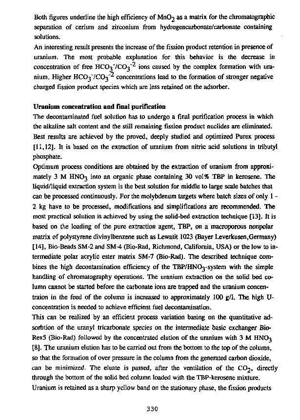
Both figures underline the high efficiency of MnC>2 as a matrix for the chromatographicseparation of cerium and zirconium from hydrogencarbonate/carbonate containingsolutions.
An interesting result presents the increase of the fission product retention in presence ofuranium. The most probable explanation for this behavior is the decrease inconcentration of free UCO^'JCO^ ions caused by the complex formation with ura-nium. Higher HCO^'/CO^ concentrations lead to the formation of stronger negativecharged fission product species which are less retained on the adsorber.
Uranium concentration and final purificationThe decontaminated fuel solution has to undergo a final purification process in which
the alkaline salt content and the still remaining fission product nuclides are eliminated.
Best results are achieved by the proved, deeply studied and optimized Purex process
[11,12]. It is based on the extraction of uranium from nitric acid solutions in tributyl
phosphate.
Optimum process conditions are obtained by the extraction of uranium from approxi-
mately 3 M HNO3 into an organic phase containing 30 vol% TBP in kerosene. The
liquid/liquid extraction system is the best solution for middle to large scale batches that
can be processed continuously. For the molybdenum targets where batch sizes of only 1 -
2 kg have to be processed, modifications and simplifications are recommended. The
most practical solution is achieved by using the solid-bed extraction technique [13]. It is
based on the loading of the pure extraction agent, TBP, on a macroporous nonpolar
matrix of polystyrene divinylbenzene such as Lewatit 1023 (Bayer Leverkusen,Germany)
[14], Bio-Beads SM-2 and SM-4 (Bio-Rad, Richmond, California, USA) or the low to in-
termediate polar acrylic ester matrix SM-7 (Bio-Rad). The described technique com-
bines the high decontamination efficiency of the TBP/HNOysystem with the simple
handling of chromatography operations. The uranium extraction on the solid bed co-
lumn cannot be started before the carbonate ions are trapped and the uranium concen-
traion in the feed of the column is increased to approximately 100 g/1. The high U-
concentration is needed to achieve efficient fuel decontamination.
This can be realized by an efficient process variation basing on the quantitative ad-
sorbtion of the uranyl tricarbonate species on the intermediate basic exchanger Bio-
Rex5 (Bio-Rad) followed by the concentrated elution of the uranium with 3 M HNO3
[8]. The uranium elution has to be carried out from the bottom to the top of the column,
so that the formation of over pressure in the column from the generated carbon dioxide,
can be minimized. The eluate is passed, after the ventilation of the CO2, directly
through the bottom of the solid bed column loaded with the TBP-kerosene mixture.
Uranium is retained as a sharp yellow band on the stationary phase, the fission products
330
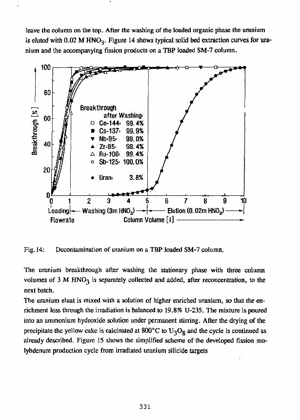
leave the column on the top. After the washing of the loaded organic phase the uranium
is eluted with 0.02 M HNOj. Figure 14 shows typical solid bed extraction curves for ura-
nium and the accompanying fission products on a TBP loaded SM-7 column.
100
80
60
I|CO
20
jn
Iu"Iff
• MIf
Breakthrough' after Washing-
• Ce-144. 99.4%• Cs-137: 99.9%• Nb-95= 99.0%A Zr-95= 99.4%A Ru-106= 99.4%o Sb-125= 100.0%
• Uran= 3.8%
//
///
/
/
0 1 2 3 4Loading [— Washing (3m HN03) —Flowrate Column Volume [I]
6 7 8 9Elution (0.02m HN03)-
10
Fig. 14: Decontamination of uranium on a TBP loaded SM-7 column.
The uranium breakthrough after washing the stationary phase with three column
volumes of 3 M HNO3 is separately collected and added, after reconcentration, to the
next batch.
The uranium eluat is mixed with a solution of higher enriched uranium, so that the en-
richment loss through the irradiation is balanced to 19.8% U-235. The mixture is poured
into an ammonium hydroxide solution under permanent stirring. After the drying of the
precipitate the yellow cake is calcinated at 800°C to UgOg and the cycle is continued as
already described. Figure 15 shows the simplified scheme of the developed fission mo-
lybdenum production cycle from irradiated uranium silicide targets
331
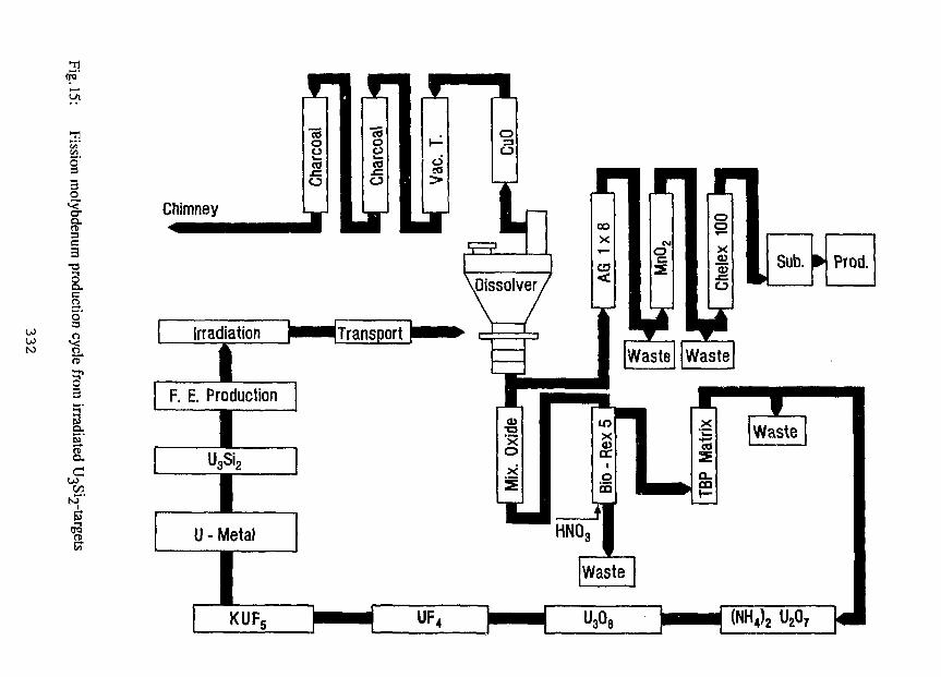
21
§
Ic3
5I
Prod.
KUF
[I] A.A. Sameh, H.J. Ache; Radiochim. Acta, No. 41, 1987, p. 65
[2] G.F. VandeGrift, J.D. Kwok, S.L. Marshall, D.R. Vissers, J.E. Matos; Interna-
tional Meeting on Reduced Enrichment for Research and Test Reactors(RERTR), Sept. 28 th - Oct. 2 n d 1987 in Buenos Aires, Argentine
[3] A.A. Sameh, A. Bertram-Berg; German patent application P4231955.2, Sept.
1992[4] A.A. Sameh, M. Reich; German patent No. 3904167, April 1990
[5] A.A. Sameh, W. Leifeld; German patent application P4231997.8, Sept. 1992
[6] A.A. Sameh, J. Hoogveldt, J. Reinhardt; German patent 2610948, Sept. 1979,
USA patent 4094953, June 1978
[7] A.A. Sameh, J. Hoogveldt, J. Reinhardt; German patent 2758783, November
1980
[8] A.A. Sameh, J. Haag; German patent 3144974, August 1985; USA patent
4460547, July 1984
[9] A.A. Sameh, J. Haag; German patent 3428877, October 1990; USA patent
4694768, August 1987
[10] A.A. Sameh, U. Bendt, W. Rottmann, W. Leifeld, U. Kaminski; International
Conference on Nuclear Fuel Reprocessing and Waste Management RECOD
87, 23 r d -27 t h of August 1987 in Paris, France
[II] R.G. Wymer, B.L. Vondra; Light Water Reactor Fuel Cycle, CRC Press, Inc.
Boca Raton, Florida
[12] H.J. Bleyl, D. Ertl, H. Goldacker, G. Petrich, J. Romer, H. Schmieder; Kern-
technik 55, No.l, 1990, p. 21
[13] R. Kroebel, A. Maier; Int. Solv. Extr. Conference in Lyon, France, 1974, 35, p.
2095, France
[14] H. Eschrich, W. Ochsenfeld; Sep. Sci. Technology, 15, 1980, p. 697
333
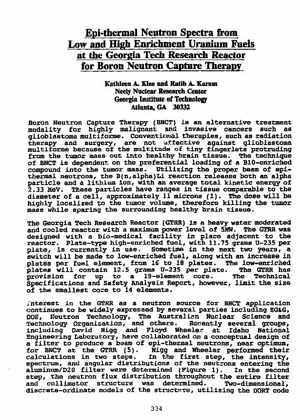
Epi-therma! Neutron Spectra fromLow and High Enrichment Uranium Fuels
at the Georgia Tech Research Reactorfor Boron Neutron Capture Therapy
Kathleen A. Klee and Ratio A. KaramNeely Nuclear Research CenterGeorgia Institute of Technology
Atlanta, GA 30332
Boron Neutron Capture Therapy (BNCT) is an alternative treatmentmodality for highly malignant and invasive cancers such asglioblastoma multiforme. Conventional therapies, such as radiationtherapy and surgery, are not affective against glioblastomamultiforme because of the multitude of tiny fingerlets protrudingfrom the tumor mass out into healthy brain tissue. The techniqueof BNCT is dependent on the preferential loading of a BIO-enrichedcompound into the tumor mass. Utilizing the proper beam of epi-thermal neutrons, the B(n,alpha)Li reaction releases both an alphaparticle and a lithium ion, with an average total kinetic energy of2.33 MeV. These particles have ranges in tissue comparable to thediameter of a cell, approximately 11 microns (1). The dose will behighly localized to the tumor volume, therefore killing the tumormass while sparing the surrounding healthy brain tissue.
The Georgia Tech Research Reactor (GTRR) is a heavy water moderatedand cooled reactor with a maximum power level of 5MW. The GTRR wasdesigned with a bio-medical facility in place adjacent to thereactor. Plate-type high-enriched fuel, with 11.75 grams U-235 perplate, is currently in use. Sometime in the next two years, aswitch will be made to low-enriched fuel, along with an increase inplates per fuel element, from 16 to 18 plates. The low-enrichedplates will contain 12.5 grams U-235 per plate. The GTRR hasprovision for up to a 19-element core. The TechnicalSpecifications and Safety Analysis Report, however, limit the sizeof the smallest core to 14 elements.
Interest in the GTRR as a neutron source for BNCT applicationcontinues to be widely expressed by several parties including EG&G,DOE, Neutron Technology, The Australian Nuclear Science andTechnology Organization, and others. Recently several groups,including David Nigg and Floyd Wheeler at Idaho NationalEngineering Laboratory, have collaborated on a conceptual design ofa filter to produce a beam of epi-thermal neutrons, near optimum,for BNCT at the GTRR {5). Nigg and Wheeler performed theircalculations in two steps. In the first step, the intensity,spectrum, and angular distributions of the neutrons entering thealuminum/D20 filter were determined (Figure 1). In the secondstep, the neutron flux distribution throughout the entire filterand collimator structure was determined. Two-dimensional,discrete-ordinate models of the structure, utilizing the DORT code
334
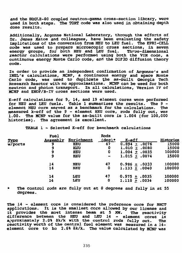
and the BUGLE-80 coupled neutron-gamma cross-section library, wereused in both steps. The TORT code was also used in obtaining depthdose results.
Additionally, Argonne National Laboratory, through the efforts ofDr. James Matos and colleagues, have been evaluating the safetyimplications of the conversion from HEU to LEU fuel. The EPRI-CELLcode was used to prepare microscopic cross sections, in sevenenergy groups, for both HEU and LEU fuel. Three-dimensionalreactor calculations were performed using both the VIM code, acontinuous energy Monte Carlo code, and the DIF3D diffusion theorycode.
In order to provide an independent confirmation of Argonne's andINEL's calculations, MCNP, a continuous energy and space MonteCarlo code, was used to duplicate the as-built Georgia TechResearch Reactor with no approximations. MCNP can be used for bothneutron and photon transport. In all calculations, Version IV ofMCNF and ENDF/B-IV cross sections were used.
K-eff calculations for 9, 14, and 19 element cores were performedfor HEU and LEU fuels. Table 1 summarizes the results. The 9 -element HEU core served as a benchmark for the calculations. Themeasured k-eff of the 9 - element HEU core, rods fully out, was1.00. The MCNP value for the as-built core is 1.004 (for 100,000histories). The agreement is excellent.
TABLE 1 - Selected K-eff for benchmark calculations
Typew/ports
FuelAssembly
9999
1414
1414
EnrichmentHEUHEUHEUHEU
HEUHEU
LEULEU
Rods(deo)*4700
470
470
K-eff0.894 + .00761.010 + .00801.004 + .00351.015 + .0074
0.986 + .00331.133 + .0040
0.975 + .00351.110 + .0034
150001500010000015000
100000100000
100000100000
* The control rods are fully out at 0 degrees and fully in at 55degrees.
The 14 - element core is considered the reference core for BNCTapplications. It is the smallest core allowed by our license andit provides the most intense beam at 5 MW. The reactivitydifference between the HEU and LEU 14 - element cores isapproximately 2.0% 6k/k with the control rods fully out. Thereactivity worth of the central fuel element was measured in a 14-element core to ba 2.6% 5k/k. The value calculated by MCNP was
335
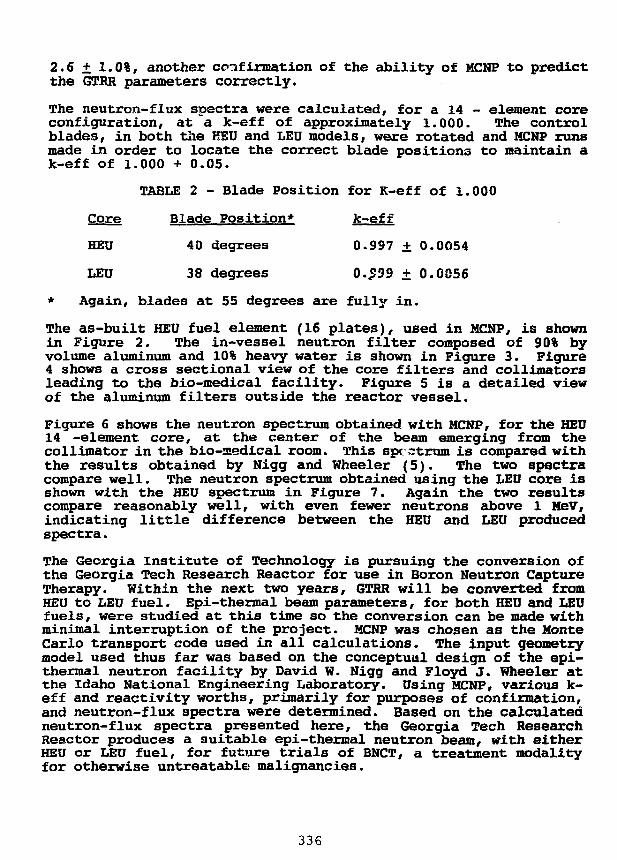
2.6 + 1.0%, another confirmation of the ability of MCNP to predictthe 6TRR parameters correctly.
The neutron-flux spectra were calculated, for a 14 - element coreconfiguration, at a k-eff of approximately 1.000. The controlblades, in both the HSU and LEU models, were rotated and MCNP runsmade in order to locate the correct blade positions to maintain ak-eff of 1.000 + 0.05.
TABLE 2 - Blade Position for K-eff of 1.000
Core Blade Position* k-eff
HEU 40 degrees 0.997 + 0.0054
LEU 38 degrees O.£99 ± 0.0056
* Again, blades at 55 degrees are fully in.
The as-built HEU fuel element (16 plates), used in MCNP, is shownin Figure 2. The in-vessel neutron filter composed of 90% byvolume aluminum and 10% heavy water is shown in Figure 3. Figure4 shows a cross sectional view of the core filters and collimatorsleading to the bio-medical facility. Figure 5 is a detailed viewof the aluminum filters outside the reactor vessel.
Figure 6 shows the neutron spectrum obtained with MCNP, for the HEU14 -element core, at the center of the beam emerging from thecollimator in the bio-medical room. This spectrum is compared withthe results obtained by Nigg and Wheeler (5). The two spectracompare well. The neutron spectrum obtained using the LEU core isshown with the HEU spectrum in Figure 7. Again the two resultscompare reasonably well, with even fewer neutrons above 1 MeV,indicating little difference between the HEU and LEU producedspectra.
The Georgia Institute of Technology is pursuing the conversion ofthe Georgia Tech Research Reactor for use in Boron Neutron CaptureTherapy. Within the next two years, 6TRR will be converted fromHEU to LEU fuel. Epi-thermal beam parameters, for both HEU and LEUfuels, were studied at this time so the conversion can be made withminimal interruption of the project. MCNP was chosen as the MonteCarlo transport code used in all calculations. The input geometrymodel used thus far was based on the conceptual design of the epi-therroal neutron facility by David W. Nigg and Floyd J. Wheeler atthe Idaho National Engineering Laboratory. Using MCNP, various k-eff and reactivity worths, primarily for purposes of confirmation,and neutron-flux spectra were determined. Based on the calculatedneutron-flux spectra presented here, the Georgia Tech ResearchReactor produces a suitable epi-thermal neutron beam, with eitherHEU or LEU fuel, for future trials of BNCT, a treatment modalityfor otherwise untreatable malignancies.
336
REFERENCES
1. Brownell, G.L. et al. "Boron Neutron Capture Therapy." ModernTrends in Radiotherapy I. New York: Appleton-Century-Crofts, 1967.132-144.
2. Brugger, R.M. et al. Summarization of Epi-therraal Neutron BeamParameters. Nuc. Tec. 98:322, June 1992.
3. Freese, Ken E. Private communication. Argonne NationalLaboratory, 1974.
4. Freese, Ken E. Private Communication. Argonne NationalLaboratory, 1990.
5. Matos, J.E. et al. "Analyses for^Conversion of the Georgia TechResearch Reactor from HEU to LEU Fuel." These proceedings.Argonne National Laboratory, 1992.
6. Nigg, D.W. and F. J. Wheeler, "Conceptual Physics Design of an Epi-Thermal Neutron Facility for Neutron Capture Therapy at the Georgiatech Research Reactor." Trans. ANS 65;146-147. June, 1992.
7. "MCNP-4, Monte Carlo Neutron and Photon Transport Code Systems,"Obtained from Radiation Shielding Information Center, Oak RidgeNational Laboratory. CCC-200A/B, 1992.
337
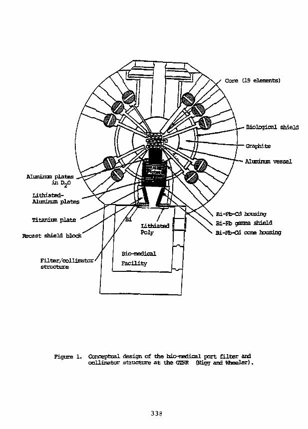
Aluminum pistesin D20
Lithiated-Aluminum plates
Titanium plate
Recast shield block
Filter/collisiatorstructure
Core (19 elements)
Biological shield
Graphite
Aluminum vessel
Bi-Eb-Cd housingBi-Eb gamna jfrp'pTflBi-Pb-Cd cone housing
Figure 1. Conceptual design of the bio-medical port filter andccllimator structure at the GTFR (Nigg and Wieeler).
338
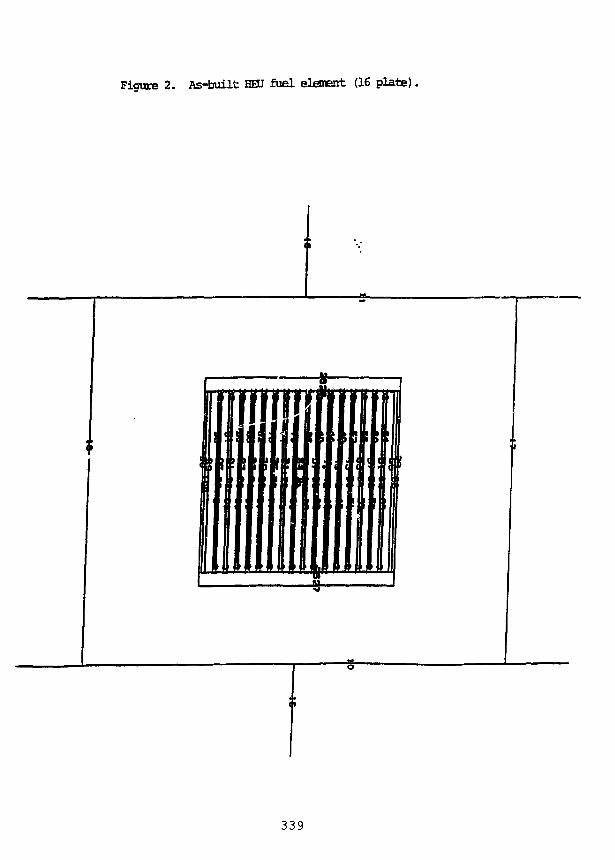
Figure 2. As-built HEU fuel element (16 plate),
339
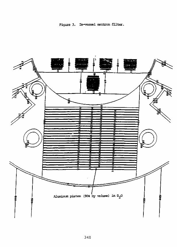
Figure 3. Ih-vessel neutron filter.
Aluminum plates (90% by volume) in
340
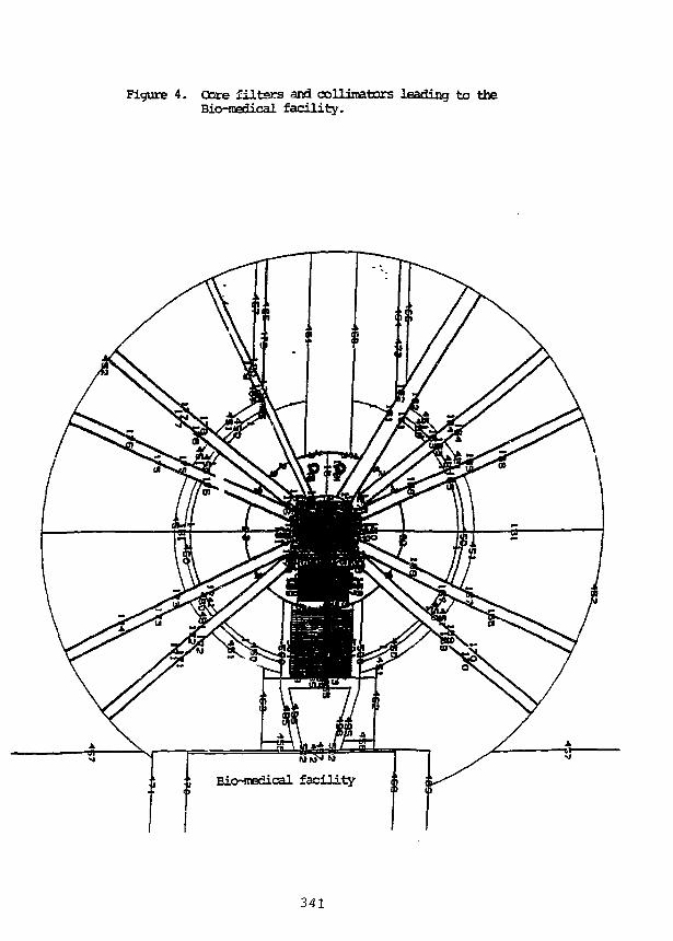
Figure 4. Core filters and collinatars leading to theBio-nedical facility.
341
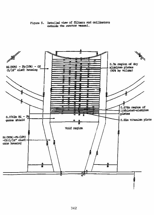
Figure 5. Detailed view of f i l t ers and collimatorsoutside tiie reactor vessel .
0.7m region of dryaluminum plates(90% by volume)
Bi(90%) - Eb(10%) - Q3(1/16" clad) housing
0.0762m Bi -ganna shield
Bi(90%)-Eb(10%)" clad)
cone housing
0.076m region oflithiated-Taluminuniplates
0.01m titanium plate
342
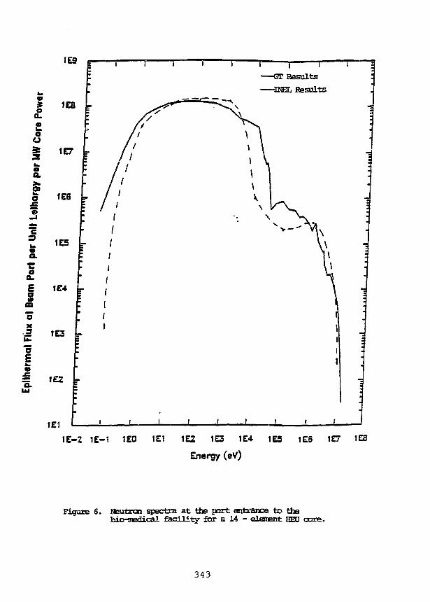
tei
——CT ResultsDEL Hesults
1E-Z IE—1 ICO 1E1 1E2 1E3 1C4- 1E5
Energy (eV)
1E6 1£7 IES
Figure 6. Weutron spectra at the part entrance to thebio-medical facility for a 14 - element HECJ core.
343
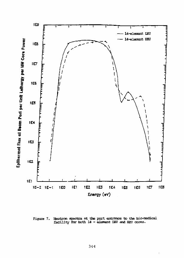
I I I
14-elanent LED
— 14-elanent HECJ
1E-Z 1E-1 1EO 1EJ 1E2 tE3 1E4
Energy (eV)
1E5 tE5 1E7 1ES
Figure 7. Neutron spectra at the part entrance to the bio-medicalfacility for both 14 - element IED and BED cores.
344

CONTRIBUTED PAPERS
345
CHILEAN FUEL ELEMENTS FABRICATION PROGRESS REPORT
J. Baeza, H. Contreras, J. Chavez,J. Klein, R. Mansilla, J. Marin and R. Medina.
COMISION CHILENA DE ENERGIA NUCLEAR1
Amunategui 95. Casilla 188-DSantiago, Chile.
ABSTRACT
Due to HEU-LEU core conversion necessity for the Chilean MTR reactors, the FuelElements Plant is being implemented to LEU nuclear fuel elements fabrication. Aglove box line for powder-compact processing designed at CCHEN, which issupposed to operate under an automatic control system, is at present under initialtests. Results of first natural uranium fuel plates manufacturing runs are shown.
INTRODUCTION
In 1982, a basic research project related to nuclear fuel fabrication started at CCHEN.Research in miniplates and nuclear fuel obtainment were the mayor aims in the early stages of thisproject. During 1985 some experience was achieved in order to design the Planta de ElementosCombustibles2, PEC. One of its first goals was the repair of the 90% enriched uranium-aluminumalloy fuel meat supplied by JEN3 for the Chilean research reactor, RECH-24. Both, fuel elementsplant and reactor are located in Lo Aguirre Nuclear Center, approximately 30 km. west fromSantiago, Chile's capital.
The plant was built during 1986, completed in 1987 and finished the fuel elements overhaulin 1988. The 31 HEU fuel elements were fully disassembled because of mechanical damagecaused by an inadequate loading system. A general criteria to reject fuel plates with scratches anddents deeper than 100 um was used. 29 elements were reassembled after a rigorous dimensionaland quality control inspection. A small plate protection was added in order to prevent mechanicaldamage during charge. The reactor loading system was modified, too. [1]
Due to worldwide HEU-LEU core conversion, LEU nuclear fuel elements for RECH-1 andRECH-2 research reactors are scheduled for future fabrication in Chile. Since then, the plant hasbeen implemented to that objective. The first nuclear fuel elements production programmed by theplant are the U3O8-AI plates 66.5 wt%, U>08 (37.5 vol%) (2.6 gm/cm3 total uranium) for theRECH-2 reactor.
1 Chilean Commission for Nuclear Energy (CCHEN).2 Fuel Elements Plant.
Junta Energia Nuclear (from Spain).4 Reactor Experimental de Chile N°2 (Experimental Reactor of Chile).
347
During an IAEA expert mission in March 1992, the first ten U3O8-AI full size fuel plates,using natural uranium, were manufactured to demonstrate the process. Some pitfalls observedduring this fabrication process are under corrective improvements at the moment, so that a finalmanufacturing simulation run should be carried out in the near future.
This report presents the actual status of the LEU plate type fuel element fabrication in Chile,with emphasis on the glove box line completion. Results of the first plate manufacturing processare also briefly reviewed here.
CCHEN LEU FUEL SUPPLY REQUIREMENTS
RECH-1 (La Reina Nuclear Center). This is a 5 MW research reactor used for radioisotopeproduction and material and irradiation tests. It has successfully been in operation with 80% HEUUAlx-alloy type fuel from 1975 to 1988 and 45% MEU fuel since then. It is scheduled to startusing LEU fuel elements not until 1997. The uranium density required for this final coreconversion must be up to 3.7 gm/cm3 [2].
RECH-2 (Lo Aguirre Nuclear Center). This is a 10 MW, open pool type research reactormoderated and cooled by light water, planned to be used in irradiation, production and training.Initially it went critical in 1977 and, due to major systems modifications, finally on September 6,1989, the reactor went critical. Characterization operations are in progress for full exploitation atfull power, which is limited now to 2 MW with HEU fuel made in Spain. Future plans intend toconvert this reactor to LEU fuel operation at 10 MW. It is programmed using U3O8-AI alloy typefuel elements with a density up to 2.6 gm/cm3 [1].
CCHEN LEU FUEL MANUFACTURING FACILITIES
CONVERSION PLANT. The UF6-U3Q8 Conversion Plant will convert ammoniumdiuranite (ADU) into high-fired U3O8 powder, necessary to fulfill the fuel plate manufacturingrequirements. The plant is under licensing process and is regularly providing U3O8 natural uraniumto the Fuel Elements Plant for manufacturing simulation runs.
FUEL FABRICATION PLANT. The Fuel Elements Plant, built in 1986, was first used tooverhaul the fuel elements of the RECH-2 reactor. The main steps of that work includedstructural components manufacturing (side plates, bolts, spacers and holders), overall inspectionand measurements, fuel elements disassembling, fuel plates inspection, cleaning, X-ray andflatness checking and fuel elements reassembling.
The manufacturing area is divided into the following six distinguished sectors.
Glove Box Line. In order to fulfill special requirements to manipulate uranium powders, a 5glove box line was installed. It allows working under safe conditions with a controlledatmosphere, whether humidity or oxygen controlled, depending the fuel type to prepare, U3O8-AIor silicides. This line will be explained further in more details.
Machining and Assembling Line. In general, this line includes those conventionalmachines that can be found in any machine shop, in order to manufacture the structural pieces ofthe fuel elements. A special mention should be done to the universal (column-and-knee) typemilling machine with memory-programmable control system.
348
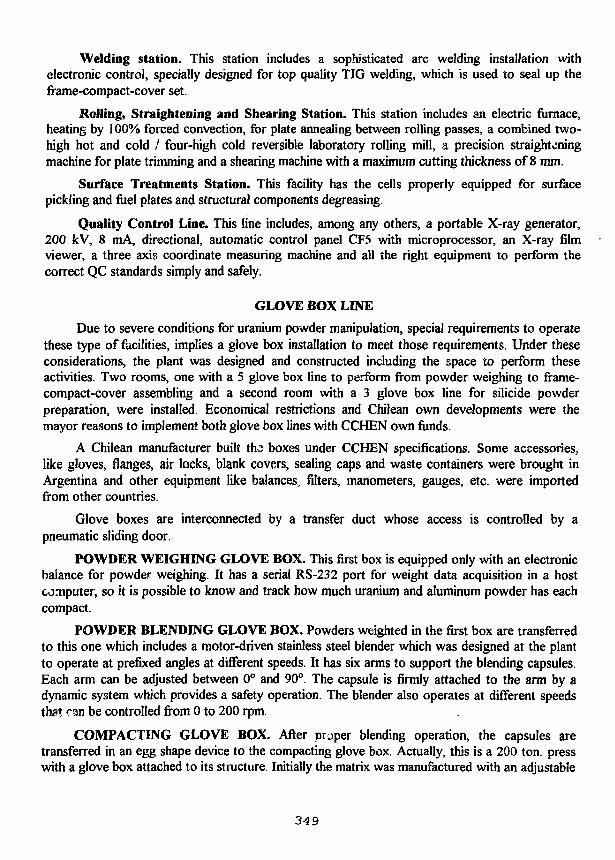
Welding station. This station includes a sophisticated arc welding installation withelectronic control, specially designed for top quality TIG welding, which is used to seal up theframe-compact-cover set.
Rolling, Straightening and Shearing Station. This station includes an electric furnace,heating by 100% forced convection, for plate annealing between rolling passes, a combined two-high hot and cold / four-high cold reversible laboratory rolling mill, a precision straighteningmachine for plate trimming and a shearing machine with a maximum cutting thickness of 8 mm.
Surface Treatments Station. This facility has the cells properly equipped for surfacepickling and fuel plates and structural components degreasing.
Quality Control Line. This line includes, among any others, a portable X-ray generator,200 kV, 8 mA, directional, automatic control panel CF5 with microprocessor, an X-ray filmviewer, a three axis coordinate measuring machine and all the right equipment to perform thecorrect QC standards simply and safely.
GLOVE BOX LINE
Due to severe conditions for uranium powder manipulation, special requirements to operatethese type of facilities, implies a glove box installation to meet those requirements. Under theseconsiderations, the plant was designed and constructed including the space to perform theseactivities. Two rooms, one with a 5 glove box line to perform from powder weighing to frame-compact-cover assembling and a second room with a 3 glove box line for silicide powderpreparation, were installed. Economical restrictions and Chilean own developments were themayor reasons to implement both glove box lines with CCHEN own funds.
A Chilean manufacturer built ths boxes under CCHEN specifications. Some accessories,like gloves, flanges, air locks, blank covers, sealing caps and waste containers were brought inArgentina and other equipment like balances, filters, manometers, gauges, etc. were importedfrom other countries.
Glove boxes are interconnected by a transfer duct whose access is controlled by apneumatic sliding door.
POWDER WEIGHING GLOVE BOX. This first box is equipped only with an electronicbalance for powder weighing. It has a serial RS-232 port for weight data acquisition in a hostcomputer, so it is possible to know and track how much uranium and aluminum powder has eachcompact.
POWDER BLENDING GLOVE BOX. Powders weighted in the first box are transferredto this one which includes a motor-driven stainless steel blender which was designed at the plantto operate at prefixed angles at different speeds. It has six arms to support the blending capsules.Each arm can be adjusted between 0° and 90°. The capsule is firmly attached to the arm by adynamic system which provides a safety operation. The blender also operates at different speedsthat can be controlled from 0 to 200 rpm.
COMPACTING GLOVE BOX. After proper blending operation, the capsules aretransferred in an egg shape device to the compacting glove box. Actually, this is a 200 ton. presswith a glove box attached to its structure. Initially the matrix was manufactured with an adjustable
34 9
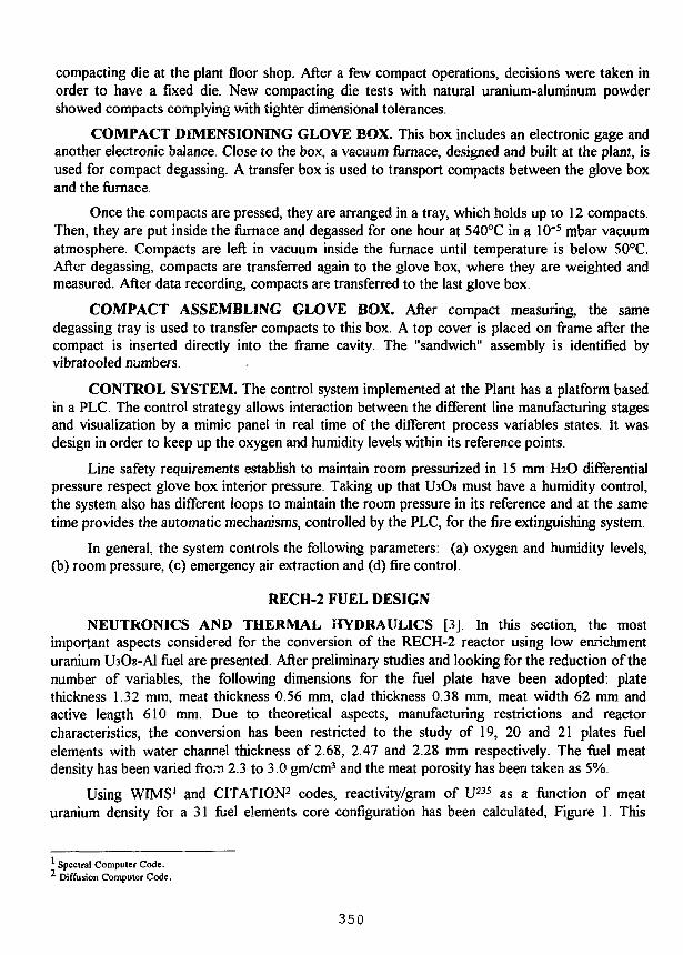
compacting die at the plant floor shop. After a few compact operations, decisions were taken inorder to have a fixed die. New compacting die tests with natural uranium-aluminum powdershowed compacts complying with tighter dimensional tolerances.
COMPACT DIMENSIONING GLOVE BOX. This box includes an electronic gage andanother electronic balance. Close to the box, a vacuum furnace, designed and built at the plant, isused for compact degassing. A transfer box is used to transport compacts between the glove boxand the furnace.
Once the compacts are pressed, they are arranged in a tray, which holds up to 12 compacts.Then, they are put inside the furnace and degassed for one hour at 540°C in a 10"5 mbar vacuumatmosphere. Compacts are left in vacuum inside the furnace until temperature is below 50°C.After degassing, compacts are transferred again to the glove box, where they are weighted andmeasured. After data recording, compacts are transferred to the last glove box.
COMPACT ASSEMBLING GLOVE BOX. After compact measuring, the samedegassing tray is used to transfer compacts to this box. A top cover is placed on frame after thecompact is inserted directly into the frame cavity. The "sandwich" assembly is identified byvibrafooled numbers.
CONTROL SYSTEM. The control system implemented at the Plant has a platform basedin a PLC. The control strategy allows interaction between the different line manufacturing stagesand visualization by a mimic panel in real time of the different process variables states. It wasdesign in order to keep up the oxygen and humidity levels within its reference points.
Line safety requirements establish to maintain room pressurized in 15 mm H2O differentialpressure respect glove box interior pressure. Taking up that LbOs must have a humidity control,the system also has different ioops to maintain the room pressure in its reference and at the sametime provides the automatic mechanisms, controlled by the PLC, for the fire extinguishing system.
In general, the system controls the following parameters: (a) oxygen and humidity levels,(b) room pressure, (c) emergency air extraction and (d) fire control.
RECH-2 FUEL DESIGN
NEUTRONICS AND THERMAL HYDRAULICS [3] In this section, the mostimportant aspects considered for the conversion of the RECH-2 reactor using low enrichmenturanium LbOs-Al fuel are presented. After preliminary studies and looking for the reduction of thenumber of variables, the following dimensions for the fuel plate have been adopted: platethickness 1.32 mm, meat thickness 0.56 mm, clad thickness 0.38 mm, meat width 62 mm andactive length 610 mm. Due to theoretical aspects, manufacturing restrictions and reactorcharacteristics, the conversion has been restricted to the study of 19, 20 and 21 plates fuelelements with water channel thickness of 2.68, 2.47 and 2.28 mm respectively. The fuel meatdensity has been varied from 2.3 to 3.0 gm/cm3 and the meat porosity has been taken as 5%.
Using WIMS1 and CITATION2 codes, reactivity/gram of U235 as a function of meaturanium density for a 31 fuel elements core configuration has been calculated, Figure 1. This
Spectral Computer Code.* Diffusion Computer Code.
350
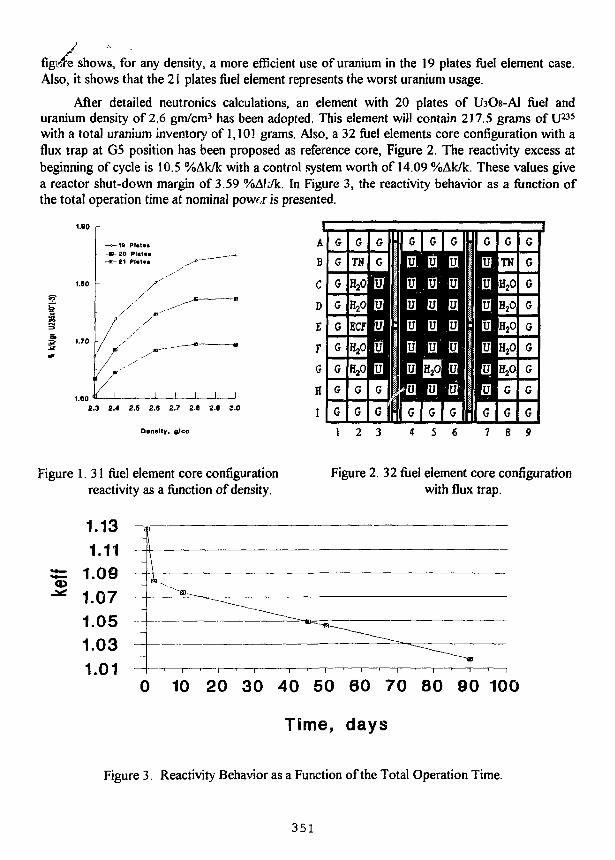
ewe sfigitfe shows, for any density, a more efficient use of uranium in the 19 plates fuel element case.Also, it shows that the 21 plates fuel element represents the worst uranium usage.
After detailed neutronics calculations, an element with 20 plates of ifaOs-Al fuel anduranium density of 2.6 gm/cm3 has been adopted. This element will contain 217.5 grams of U235
with a total uranium inventory of 1,101 grams. Also, a 32 fuel elements core configuration with aflux trap at G5 position has been proposed as reference core, Figure 2. The reactivity excess atbeginning of cycle is 10.5 %Ak/k with a control system worth of 14.09 %Ak/k. These values givea reactor shut-down margin of 3.59 %Af:/k. In Figure 3, the reactivity behavior as a function ofthe total operation time at nominal powrr is presented.
5
-20 PIMM- 21 Plutm»
r"i I
2.3 2.4 2.S 2.0 2.7 2.6 2.« 3.0
Density, g/cc
Figure 1. 31 fuel element core configurationreactivity as a function of density.
0 10 20 30 40 50 60 70 80 90 100
Time, days
Figure 3. Reactivity Behavior as a Function of the Total Operation Time.
351
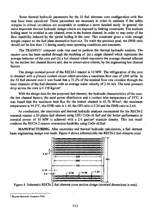
Some thermal hydraulic parameters for the 32 fuel elements core configuration with fluxtrap have been calcubied. These parameters are necessary in order to estimate if the safetymargins in critical conditions are acceptable to continue a more detailed study. In general, themore important thermal hydraulic design criteria are imposed by limiting constraints. The nucleateboiling must be avoided in any channel, even in the hottest channel, in order to stay away of theflow instability induced by the partial boiling in the core. This constraint gives a wide enoughmargin respect to the fuel plate destructive burn-out. To reach the previous goal, the DNB ratioshould not be less than 1.5 during steady-state operating conditions and transients.
The TRANSV21 computer code was used to perform the thermal hydraulic analysis. Thereactor core has been studied through the modeling of: (a) a single channel which represents theaverage behavior of the core and (b) a hot channel which represents the average channel affectedby the nuclear hot channel factors and, due to conservative criteria, by the engineering hot channelfactors.
The design nominal power of the RECH-2 reactor is 10 MW. The refrigeration of the coreis obtained with a primary coolant circuit which provides a maximum flow rate of 1200 m3/hr. Inthe 32 fuel element core it was found that a 73.2% of the nominal flow rate circulate through theinner channels of the fuel elements with an average water velocity of 2.44 m/s. The total pressuredrop across the core is 0.138 Kg/cm2.
With the design data for the proposed fuel element, the hydraulic characteristics of the core,the hot channel factors, the axial power distribution and a coolant inlet temperature of 35°C, itwas found that the maximum heat flux for the hottest channel is 65.76 W/cm2, the maximumtemperature is 94.2°C, the ONB ratio is 1.44, the OFI ratio is 2.24 and the DNB ratio is 2.64.
As conclusions, the neutronics and thermal hydraulic analyses recommend for the RECH-2research reactor a 20 plates fuel element using LEU U3O8-AI fuel and the better performance atnominal power of 10 MW is achieved with a 2.6 gm/cm3 uranium density. This last resultconfirms the RECH-2 reactor conversion feasibility using LbOs-Al fuel.
MANUFACTURING. After neutronics and thermal hydraulic calculations, a fuel elementbasic engineering design was made. Figure 4 shows schematically the RECH-2 fuel element cross
2.47-
4.75-2.5-
-620-
666-
- 761-
[-0.56 r—0.38 r~1-32
761
Figure 4. Schematic RECH-2 fuel element cross section design (nominal dimensions in mm).
1 Thermal Hydraulic Computer Code.
352
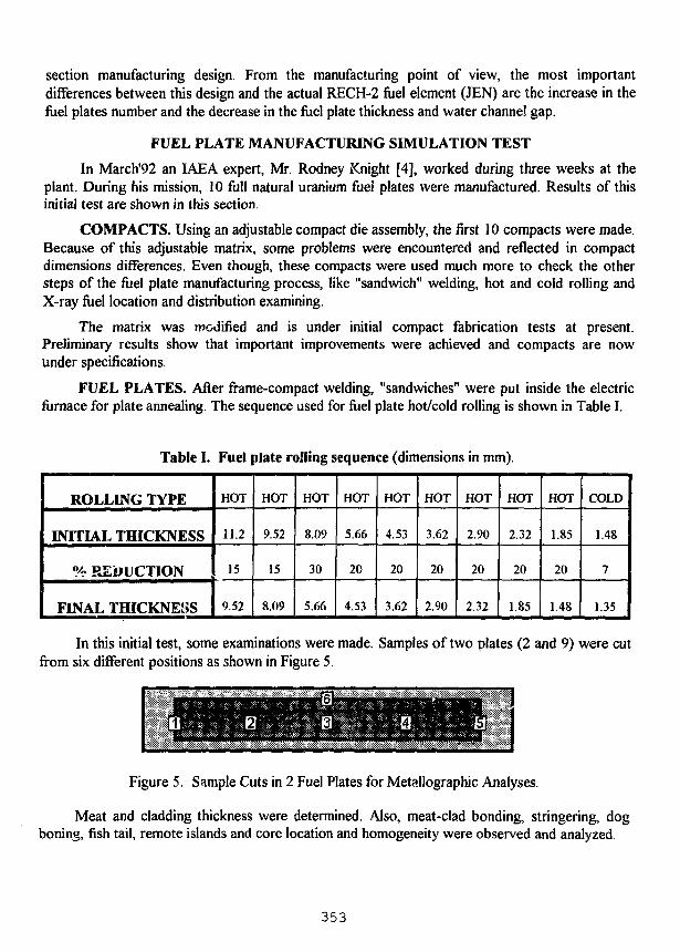
section manufacturing design. From the manufacturing point of view, the most importantdifferences between this design and the actual RECH-2 fuel element (JEN) are the increase in thefuel plates number and the decrease in the fuel plate thickness and water channel gap.
FUEL PLATE MANUFACTURING SIMULATION TEST
In March'92 an IAEA expert, Mr. Rodney Knight [4], worked during three weeks at theplant. During his mission, 10 full natural uranium fiiei plates were manufactured. Results of thisinitial test are shown in this section.
COMPACTS. Using an adjustable compact die assembly, the first 10 compacts were made.Because of this adjustable matrix, some problems were encountered and reflected in compactdimensions differences. Even though, these compacts were used much more to check the othersteps of the fuel plate manufacturing process, like "sandwich" welding, hot and cold rolling andX-ray fuel location and distribution examining.
The matrix was modified and is under initial compact fabrication tests at present.Preliminary results show that important improvements were achieved and compacts are nowunder specifications.
FUEL PLATES. After frame-compact welding, "sandwiches" were put inside the electricfurnace for plate annealing. The sequence used for fuel plate hot/cold rolling is shown in Table I.
Table I. Fuel plate rolling sequence (dimensions in mm).
ROLLING TYPE
INITIAL THICKNESS
% REDUCTION
FINAL THICKNESS
HOT
11.2
15
9.52
HOT
9.52
15
8.09
HOT
8.09
30
5.66
HOT
5.66
20
4.53
HOT
4.53
20
3.62
HOT
3.62
20
2.90
HOT
2.90
20
2.32
HOT
2.32
20
1.85
HOT
1.85
20
1.48
COLD
1.48
7
1.35
In this initial test, some examinations were made. Samples of two plates (2 and 9) were cutfrom six different positions as shown in Figure 5.
Figure 5. Sample Cuts in 2 Fuel Plates for Metallographic Analyses.
Meat and cladding thickness were determined. Also, meat-clad bonding, stringering, dogboning, fish tail, remote islands and core location and homogeneity were observed and analyzed.
353
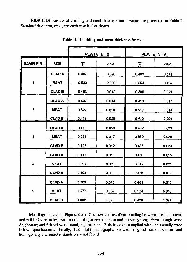
RESULTS. Results of cladding and meat thickness mean values are presented in Table 2.Standard deviation, an-] , for each case is also shown.
Table II. Cladding and meat thickness (mm).
SAMPLE N°
1
2
3
4
5
SIDE
CLAD A
MEAT
CLADB
CLAD A
MEAT
CLADB
CLAD A
MEAT
CLADB
CLAD A
MEAT
CLADB
CLAD A
MEAT
CLADB
PLATE N°2
~X
0.407
0.533
0.403
0.407
0.522
0.415
0.410
0.524
0.428
0.410
0.533
0.408
0.383
0.577
0.392
on-1
0.020
0.020
0.012
0.014
0.028
0.020
0.020
0.017
0.012
0.018
0.023
0.019
0.013
0.039
0.022
PLATE N°9
~X
0.401
0.554
0.399
0.416
0.517
0.410
0.482
0.570
0.435
0.430
0.517
0.426
0.401
0.524
0.420
<m-1
0.014
0.037
0.021
0.017
0.018
0.009
0.033
0.029
0.023
0.015
0.021
0.017
0.018
0.040
0.024
Metallographic cuts, Figures 6 and 7, showed an excellent bonding between clad and meat,and full LbOs particles, with no (shrinkage) comminution and no stringering. Even though somedog boning and fish tail were found, Figures 8 and 9, their extent complied with and actually werebelow specifications. Finally, fuel plate radiographs showed a good core location andhomogeneity and remote islands were not found.
354
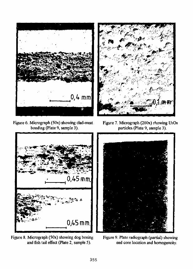
r-h
fL %
HB•F "^|
1
f
Is.
' *
* ••
w
*
*
r
*7
2*
JS
4}. <
^ - ' r
IS*
Figure 6. Micrograph (50x) showing clad-meat Figure 7. Micrograph (200x) showingbonding (Plate 9, sample 3). particles (Plate 9, sample 3).
Figure 8. Micrograph (50x) showing dog boningand fish tail effect (Plate 2, sample 5).
Figure 9. Plate radiograph (partial) showingend core location and homogeneity.
355
CONCLUSIONS AND FUTURE WORKS
- Initial results in fuel elements fabrication using natural uranium, show that future MTRnuclear fuel elements under Chilean specifications and design should be manufactured at CCHEN.
- The simulated fabrication process to manufacture fuel plates using natural uranium and toassemble fuel elements should continue to May 1993.
- The Fuel Elements Plant is under final tests and licensing and should start in the nearfuture with LEU MTR nuclear fuel fabrication and should satisfy Chilean nuclear fuel necessities.
- Future research and development in silicides is planned to start in 1993 to satisfy nextRECH-1 nuclear fuel necessity.
ACKNOWLEDGMENTS
The authors would like to thank the fuel elements plant technicians, N. Salazar, C.Marchant, V. Cepeda and F. Fernandez who made contributions and suggestions in manytechnical details.
REFERENCES
[1] G. Torres, "Puesta en Servicio del Reactor Experimental del CEN Lo Aguirre", NucleotecnicaN° 17, October 1989.
[2] A. Poblete, "Gestion de Combustible 1989-1997 del Reactor RECH-1 de la Reina", TechnicalInform N° RLR-06-1990, May 1990.
[3] J. Klein, R. Medina, C. Henriquez y O. Mutis, "Analisis Neutronico y Termohidraulico para laDefinition del Elemento Combustible de Bajo Enriquecimiento del RECH-2", TechnicalInform, Reactor Phisics Division, 1992.
[4] R. Knight, "Fabrication of Fuel Plates Using Either U3O8 or U3Si2M, IAEA Expert Report,April 1992.
356
LETTER FROM MR. SUN RONGXIAN, NUCLEAR POWER INSTITUTE OF CHINA
Dr. Karsten HaackReactor DR3Risa National LaboratoryPost Box 4 9DK 4000, Roskilde, Denmark
September 1, 1992
Dear Dr. Karsten Haack:
Thank you very much for your invitation to the 1992 RERTRInternational Conference in Roskilde, Denmark. I regret that I will notbe able to attend the conference due to a lack of funds.
Nevertheless, as you are aware, I am interested in the conference.I am curious as to the progress being made by my colleagues in eachcountry and would also like to present my own achievements andexperiences. Please send me a copy of the papers presented at theconference, an agenda, a list of participants, and the tiin̂ and locationof the 16th RERTR International Conference.
In turn, the following is a brief presentation that I have preparedfor you and the other attendants concerning the progress of RERTR in ourinstitute:
The Nuclear Power Institute of China (NPIC) has produced the U3Si2~Aldispersion fuel elements for the domestic three MW pool reactor and forthe Pakistan Research Reactor (PARR). These fuel elements are inoperation at the present time. The original power of PARR is five MW;however, after improvement, the power reached nine MW and the thermalneutron flux rose to 1.4E14 in the core. When the fuel elements were putinto the PARR for 10 months, their condition did not change visibly andno contaminants were found in the water system. The power will soonreach 10 MW, the designated new value.
In addition, NPIC has finished another batch of fuel elements forPARR this year. My fellow researchers took part in the production andfurthered improved the fabricating process as follows:
1. Doqbone: As mentioned in an earlier paper, we improved theframe construction. As a result, the dogbone was effectively reduced.However, the specification of PARR fuel elements requires a minimumcladding thickness of 0.30 mm; yet, this is difficult. So, we againimproved the property of the frame to meet the requirements.
2. White spots: As mentioned above, the improved frameconstruction can also effectively eliminate stray fuel particles from thecompact during assembling and rolling. Six fuel plates out of 670produced this year have white spots on unpermitted areas; however, fiveplates out of the six mentioned above were relieved by excavating thefuel particles. In order discover the reason, we carefully analyzed thefabricating process and ultimately found some particles adhering to the
357
compact surface after degassing. On the average, about 1.2 mg powder wascollected from the surface of each compact. By removing the powder andusing the improved frame, the white spots were basically eliminated.
3 . Blister: There are many factors affecting bonding quality, suchas surface treatment and recontamination of the frame and cover, etc.However, we .cound some small blisters in meat-free areas near the meat.Such a phenomenon depends on the heating schedule. Before the first passof rolling, if the billet is held in the furnace for enough time and thetemperature does not rise during later rolling, this kind of blister willfail to appear.
4. Detecting meat oxidation by NDT: As mentioned in our earlierpaper, if the billets were not fully protected from oxidation during theinitial heating, the end of the meat would become grayish-black. Nowthat we can detect the oxidation area, this provides the guidancenecessary to the protective effort and insures the quality of fuel platesby using ultrasonic equipment.
NPIC is willing to cooperate with the colleagues in each country ondeveloping new fuel elements and providing U3Si2-Al plate-type fuelelements and its manufacturing techniques to the user.
Regards.
Yours Sincerely
Sun Rongxian
Nuclear Materials DepartmentNuclear Power Institute of ChinaPost Box 191-106 Chengdu61005, China
358
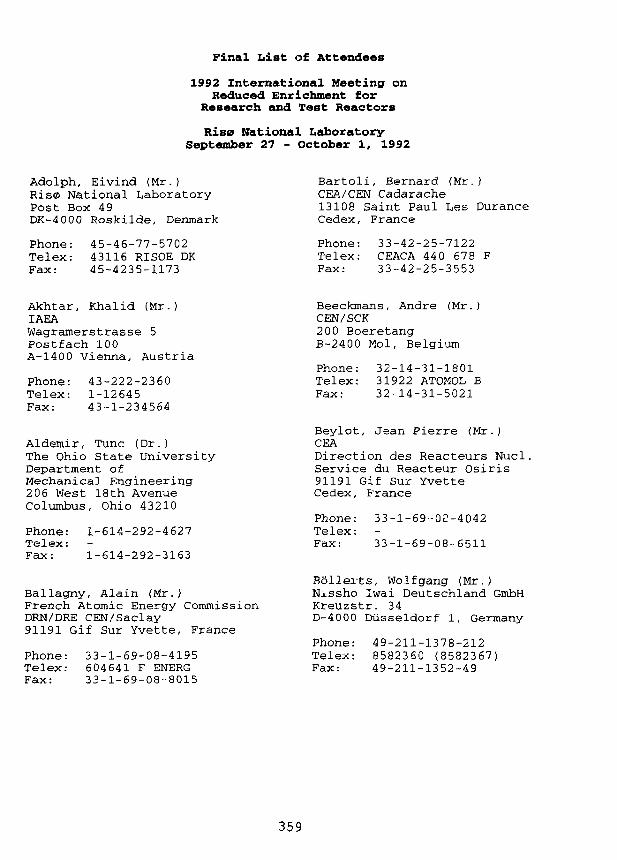
Final List of Attendees
1992 International Meeting onReduced Enrichment for
Research and Test Reactors
Rise National LaboratorySeptember 27 - October 1, 1992
Adolph, Eivind (Mr.)Ris0 National LaboratoryPost Box 49DK-4000 Roskilde, Denmark
Phone: 45-46-77-5702Telex: 43116 RISOE DKFax: 45-4235-1173
Bartoli, Bernard (Mr.)CEA/CEN Cadarache13108 Saint Paul Les DuranceCedex, France
Phone: 33-42-25-7122Telex: CEACA 44 0 678 FFax: 33-42-25-3553
Akhtar, Khalid (Mr.)IAEAWagramerstrasse 5Postfach 100A-1400 Vienna, Austria
Phone: 43-222-2360Telex: 1-12645Fax: 43-1-234564
Aldemir, Tune (Dr.)The Ohio State UniversityDepartment ofMechanical Engineering206 West 18th AvenueColumbus, Ohio 43210
Phone: 1-614-292-4627Telex:Fax: 1-614-292-3163
Ballagny, Alain (Mr.)French Atomic Energy CommissionDRN/DRE CEN/Saclay91191 Gif Sur Yvette, France
Phone: 33-1-69-08-4195Telex: 604641 F ENERGFax: 33-1-69-08-8015
Beeckmans, Andre (Mr.)CEN/SCK200 BoeretangB-2400 Mol, Belgium
Phone: 32-14-31-1801Telex: 31922 ATOMOL BFax: 32-14-31-5021
Beylot, Jean Pierre (Mr.)CEADirection des Reacteurs Nucl.Service du Reacteur Osiris91191 Gif Sur YvetteCedex, France
Phone: 33-1-69-02-4042Telex:Fax: 33-1-69-08-6511
Bollerts, Wolfgang (Mr.)Nissho Iwai Deutschland GmbHKreuzstr. 34D-4000 Diisseldorf 1, Germany
Phone: 49-211-1378-212Telex: 8582360 (8582367)Fax: 49-211-1352-49
359
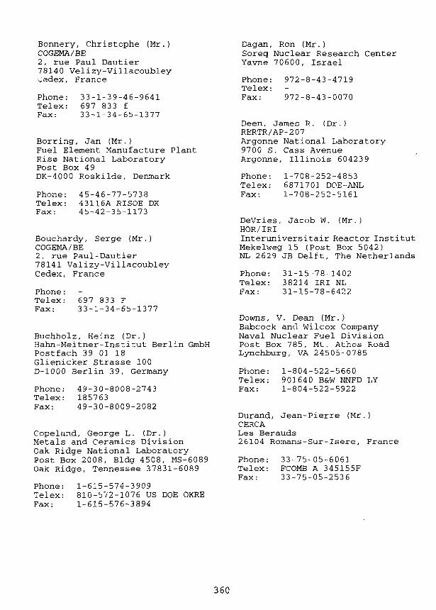
Bonnery, Christophe (Mr.)COGEMA/BE2, rue Paul Dautier78140 Velizy-Villacoubley~edex, France
Phone: 33-1-39-46-9641Telex: 697 833 fFax: 33-1-34-65-1377
Borring, Jan (Mr.)Fuel Element Manufacture PlantRise> National LaboratoryPost Box 4 9DK-4000 Roskilde, Denmark
Phone: 45-46-77-5738Telex: 43116A RISOE DKFax: 45-42-35-1173
Bouchardy, Serge (Mr.)COGEMA/BE2, rue Paul-Dautier78141 Valizy-VillacoubleyCedex, France
Phone:Telex: 697 833 FFax: 33-1-34-65-1377
Buchholz, Heinz (Dr.)Hahn-Meitner-Institut Berlin GmbHPostfach 39 01 18Glienicker Strasse 100D-1000 Berlin 39, Germany
Phone: 49-30-8008-2743Telex: 185763Fax: 49-30-8009-2082
Copeland, George L. (Dr.)Metals and Ceramics DivisionOak Ridge National LaboratoryPost Box 2008, Bldg 4508, MS-6089Oak Ridge, Tennessee 37831-6089
Phone: 1-615-574-3909Telex: 810-572-1076 US DOE OKREFax: 1-615-576-3894
Dagan, Ron (Mr.)Soreg Nuclear Research CenterYavne 70600, Israel
Phone: 972-8-43-4719Telex:Fax: 972-8-43-0070
Deen, James R. (Dr.)RERTR/AP-207Argonne National Laboratory9700 S. Cass AvenueArgonne, Illinois 604239
Phone: 1-708-252-4853Telex: 6871701 DOE-ANLFax: 1-708-252-5161
DeVries, Jacob W. (Mr.)HOR/IRIInteruniversitair Reactor InstitutMekelweg 15 (Post Box 5042)NL 2629 JB Delft, The Netherlands
Phone: 31-15-78-1402Telex: 38214 IRI NLFax: 31-15-78-6422
Downs, V. Dean (Mr.)Babcock and Wilcox CompanyNaval Nuclear Fuel DivisionPost Box 785, Mt. Athos RoadLynchburg, VA 24505-0785
Phone: 1-804-522-5660Telex: 901640 B&W NNFD LYFax: 1-804-522-5922
Durand, Jean-Pierre (Mr.)CERCALes Berauds26104 Romans-Sur-Isere, France
Phone: 33-75-05-6061Telex: FCOMB A 345155FFax: 33-75-05-2536
360
Fanjas, Yves (Mr.)CERCALes Berauds26104 Romans-Sur-Isere, France
Phone: 33-75-05-6061Telex: FCOMB A 345155FFax: 33-75-05-2536
Floto, Heinz (Mr.)Risa National LaboratoryPost Box 49DK-4000 Roskilde, Denmark
Phone: 45-4-677-4355Telex: 43116A RISOE DKFax: 45-4-675-5052
Fukushima, Shonosuke (Mr.)Nissho Iwai Corporation4-5, Akasaka 2-ChomeMinato-Ku, Tokyo 107 Japan
Phone: 81-3-588-2794Telex: 22233Fax: 81-3-588-4924
Fuse, Peter-Michael (Mr.)NUKEM GmbHPostfach 1313Industriestrasse 13D-8755 Alzenau, Germany
Phone: 49-6023-911-604Telex: 4188 233 nuka dFax: 49-6023-911-600
Futamura, Yoshiaki (Dr.)Japan Atomic Energy ResearchInstitute (JAERI)Tokai-mura, Naka-gunIbaraki-ken, Japan 311-13
Phone: 81-292-67-4111, x 4300Telex: J24596Fax: 81-292-67-7144
Gevers, Arthur (Dr.)Comm of the European CommunitiesJoint Research Center PettenPost Box 2 1755 ZG PettenThe Netherlands
Phone: 31-2246-5129Telex: 57211 REACPFax: 31-2246-1449
Goutx, Daniel (Mr.)COGEMA2, rue Paul Dautier78141 Valizy-VillacoublayCedex, France
Phone: 33-1-39-46-9641Telex: 697 833 fFax: 33-1-34-65-1377
Gr0nberg, LisbethRis0 National LaboratoryPost Box 49DK-4000 Roskilde, Denmark
Phone: 45-46-77-4608Telex: 43116A RISOE DKFax: 45-42-35-1173
Gruber, Gerhard (Mr.)MGR MTR Fuel ServicesAlzenau BranchFuel Cycle Services Div.,Nukem GmbHPostfach 1313, Industriestr 13D-S755 Alzenau, Germany
Phone: 49-6023-500-609Telex: 4188233 NUKA DFax: 49-6023-500-600
Guiheux, Jean MichelCOGEMA/DC2, rue Paul Dautier78140 Velizy-VillacoublayCedex, France
Phone: 33-1-39-46-9641Telex: 697 833 fFax: 33-1-34-65-1377
361
Haack, Karsten (Mr.)Ris0 National LaboratoryPost Box 49DK-4000 Roskilde, Denmark
Phone: 45-46-77-4302Telex: 43116A RISOE DKFax: 45-46-75-5052
Hurand, Jean-Pierre (Mr.)CERCALes Berauds26104 Romans-Sur-Isere, France
Phone: 33-75-05-6061Telex: FCOMB A 345155FFax: 33-75-05-2536
Hakansson, Rune (Mr.)Studsvik Nuclear ABS-61182 Nykoping, Sweden
Phone: 46-155-22260Telex: 64013 STUDS SFax: 46-155-63070
Harbonnier, Gerard (Mr.)CERCALes Berauds26104 Romans-Sur-IsereFrance
Phone: 33-75-05-6061Telex: FCOMB A 345155FFax: 33-75-05-2536
Hassel, Horst W. (Mr.)NUKEM GmbHPostfach 1313D-8755 Alzenau, Germany
Phone: 49-6023-500-380Telex: 4188233 NUKA DFax: 49-6023-500-382
Hofman, Gerard L. (Dr.)EBR II-ANL WestArgonne National Laboratory9700 South Cass AvenueArgonne, Illinois 60439
Phone: 1-708-252-6683Telex: 6871701 DOE-ANLFax: 1-708-252-5161
Hwang, Woan (Mr.)Korea Atomic Energy Res InstituteDaeduk Science TownPost Box 7Daej'm 305353, Korea
Phone: 82-42-820-2309Telex: 45553 kaeri kFax: 82-42-820-2702
Ichikawa, Hiroki (Mr.)RES Reactor Tech Dev DivDept of Res Reactor OperationJapan Atomic Energy Res Institute2-4 Shirane, ShirakataTokai-mura, Naka-gunIbaraki-ken 319-11 Japan
Phone: 81-292-82 .639Telex: J24596 JAERIFax: 81-292-82-5258
Jensen, Stfren E. (Mr.)Rises National LaboratoryPost Box 49DK-4000 Roskilde, Denmark
Phone: 45-46-77-43 04Telex: 43116A RISOE DKFax: 45-46-77-55052
Jonsson, Erik (Mr.)Studsvik Nuclear ABS-611 82 NyKoping Sweden
Phone: 46-155-22260Telex: 64013 STUDS SFax: 46-155-63070
362
Kampmann, Dan (Mr.)Danish Nuclear InspectorateDatavej 163460 Birker0d, Denmark
Phone: 45-45-82-8222Telex: 2 7410 CFS DKFax: 45-45-82-0876
Kanda, Keiji (Dr.)Kyoto UniversityResearch Reactor InstituteKumatori-cho, Sennan-gunOsaka 590-04 Japan
Phone: 81-724-53-2145Telex: 5397073 KURRIA JFax: 81-724-53-0360
Karam, Ratib A. (Dr.)Meely Nuclear Research CenterGeorgia Institute of TechnologyAtlanta, Georgia 30332
Phone: 1-404-894-3120Telex: 542507 GTRIOCAAFax: 1-404-853-9325
Kim, Chang Kyu (Mr.)Korea Atomic Energy Res InstituteNuclear Materials DevelopmentDepartmentDaeduk Science TownPost Box 7Daejur 3 05-353, Korea
Phone: 82-42-820-2309Telex: 45553 kaeri kFax: 82-42-820-2702
Knop, Wolfgang (Mr.)GKSS ForschungszentrumGeestacht mbHPostfach 11 602054 Geestacht, Germany
Phone: 49-4152-871-200Telex: 218712 gkssg dFax: 49-4152-871-338
Kobayashi, Keiji (Mr.)Research Reactor InstituteKyoto UniversityKamatori-cho, Sennan-gunOsaka 590-04, Japan
Phone: 81-724-52-090Telex: 5397073 kurriajFax: 81-724-53-0360
Kobayashi, Masaru (Mr.)PECHINEY, Japan43'rd Floor, Shinjuku MitsuiBldg. 2-1-1 Nishi-ShinjukuShinjuku-ku, Tokyo 163, Japan
Phone: 81-333-49-6660Telex: 232 4895 PECHIJ JFax: 81-333-49-6770
Komori, Yoshihiro (Mr.)Oarai-Machi EstablishmentJapan Atomic Energy Res InstituteOarai-machi, Higashi-Ibaraki-gunIbaraki-ken 311-13 Japan
Phone: 81-292-67-4111Telex: J24596Fax: 81-292-64-8480
Kjems, J0rgen (Mr.)Rise National LaboratoryPost Box 49DK-4000 Roskilde, Denmark
Phone: 45-46-77-4602Telex: 43116A RISOE DKFax: 45-42-35-1173
Kozma, R. (Mr.)ECN PettenWesterduinweg 3Post Box 11755 ZG Petten, The Netherlands
Phone: 31-2246-4385Telex: 57211 REACP NLFax: 31-2246-3490
363

Krull, Wilfried (Dr.)GKSS, Reaktorstrasse 7-9Forschungszentrum GeestachtPostfach 11602054 Geestacht, Germany
Phone: 49-4152-87-1200Telex: 218712 GKSS GFax: 49-4152-87-1338
Lelievre, Bernard (Dr.)CERCALes Berauds BPN 1426104 Romans Cedex, France
Phone: 33-75-05-6000Telex: 345 155 FFax: 33-75-65-2536
Listik, Evzen (Mr.)Nuclear Research Institute250 68 Rez, Czechoslovakia
Phone: 42-2-685-7831Telex:Fax: 42-2-685-7155
Matos, James (Dr.)Engineering Physics Div.Argonne National Laboratory9700 South Cass AvenueArgonne, Illinois 60439
Phone: 1-708-252-6758Telex: 6871701 DOE-ANLFax: 1-708-252-5161
McClary, Michael V. (Mr.)Office of International AffairsUS Department of EnergyIE-13 Forrestal Building1000 Independence AvenueWashington, DC 20584
Phone: 1-202-586-6194Telex:Fax: 1-202-586-6789
McColm, Colin (Mr.)UK Atomic Energy AuthorityDounreay Thurso CaithnessScotland, United Kingdom
Phone: 44-847-62-121Telex: 75297 ATOMDY GFax: 44-847-80-3049
McDonough, Michael D. (Mr.)109 Timberline DriveConway, South Carolina 27526
Phone: 1-803-347-7699Telex:Fax: 1-803-347-0027
Michaels, Theodore (Mr.)US Nuclear Regulatory CommissionMail Stop 11H3Washington, DC 20555
Phone: 1-301-504-1102Telex: 908142 NRC-BHD WSHFax: 1-301-504-0259
Mota, Jose (Mr.)AdministratorEuratom Supply AgencyCommission of theEuropean CommunitiesRue De La Loi 200B-1049 Brussels, Belgium
Phone: 32-2-235-2399Telex: 21877 COMEU BFax: 32-2-235-0527
Muller, Hans (Mr.)Fuel Cycle Services DivisionNUKEM GmbHPostfach 110080D-6450 Hanau 11, Germany
Phone: 49-6023-500-604Telex: 4188233 NUKM DFax: 49-6023-500-600
364
Naccache, Sanir J.P. (Mr.)Export Director, CERCA9-11, Rue Georges Enesco94008 Cretail Cedex, France
Phone: 33-1-43-77-1263Telex: 264-276Fax: 33-1-46-98-9265
Nakajima, Teruo (Mr.)Japan Atomic Energy ResearchInstitute (JAERI)JRR-4 Operation DivisionTokai-mura, Naka-gunIbaraki-ken 319-11, Japan
Phone: 81-292-82-5639Telex:Fax: 81-292-82-5258
Palleck, Steve (Mr.)Senior Fuel EngineerAECL Research, Chalk RiverLabs., Chalk RiverOntario KOJ IJO, Canada
Phone: 1-613-584-3311Telex:Fax: 1-613-584-3250
Papastergiou, Constantinos (Mr.)N.R.C. DemokritosGreek Atomic Energy CommissionAghia ParaskeviAthens, Greece
Phone: 30-1-651-4118Telex: 216199 ATOM GRFax: 30-1-653-3431
Nilsson, Tage M. (Mr.)Ris0 National LaboratoryPost Box 49DK-4000 Roskilde, Denmark
Phone: 45-46-77-5774Telex: 43116A RISOE DKFax: 45-42-35-1173
Nonbal, Erik (Mr.)Ris0 National LaboratoryPost Box 49DK-4000 Roskilde, Denmark
Phone: 45-46-77-4923Telex: 43116A RISOE DKFax: 45-42-35-1173
Paillere, Jacques (Mr.)French Atomic Energy CommissionService Reacteur OsirisCEN/Saclay91191 Gif Sur Yvette, France
Phone: 33-1-69-08-4042Telex: 604641F ENERGFax: 33-1-69-08-6511
Parker, Keith A. (Mr.)UK Atomic Energy AuthorityCommercial Directorate, Rm E443Cheshire, Warrington, WA3 6ATEngland
Phone: 44-925-31-244, x 2631Telex: 629301 ATOMRY GFax: 44-925-25-2631
Pauty, Jean Francois (Mr.)COGEMA/BE2, rue Paul Dautier78140 Velizy-VillacoublayCedex, France
Phone: 33-1-39-46-9641Telex: 697 833 fFax: 33-1-34-65-1377
Porte, Philippe (Mr.)CERCA9-11 Rue Georges Enesco94008 Creteil, Cedex, France
Phone: 33-1-43-77-1263Telex: 264276Fax: 33-1-46-98-9265
365
Poupard, Jean-Francois (Mr.)CERCALes Berauds, B P 111426104 Romans, CedexFrance
Phone: 33-75-05-6120Telex: 345155Fax: 33-75-05-3958
Preble, Harry E. (Mr.)Babcock and WilcoxNaval Nuclear Fuel DivisionPost Box 785Mt. Athos RoadLynchburg, Virginia 24505-0785
Phone: 1-804-522-5660Telex: 901640 B&W NNFD LYFax: 1-804-522-5922
Quinton, Paul (Mr.)CERCA9-11 Rue Georges Enesco94008 Creteil, Cedex, France
Phone: 33-1-43-77-1263Telex: CERCA 264 276Fax: 33-1-46-98-9265
Qvist, Jens (Mr.)Rise National LaboratoryPost Box 49DK-4000 Roskilde, Denmark
Phone: 45-46-77-4323Telex: 43116A RISOE DKFax: 45-42-35-1173
Raisonnier, Daniele (Mr.)Transnucleaire, SA11 bis rue Christophe Colomb75008 Paris, France
Phone: 33-1-47-20-2608Telex: 280 992Fax: 33-1-47-20-2608
Ravenscroft, Norman (Mr.)Edlow International Company1815 N. Street, N.W., Suite 910Washington, DC 20006 USA
Phone: 1-202-833-8237Telex: 64387Fax-. 1-202-483-4840
Reasor, Nathaniel H. (Mr.)Babcock and WilcoxNaval Nuclear Fuel DivisionPost Box 785Lynchburg, Virginia 24505
Phone: 1-804-522-6239Telex: 901640 B&W NNFD LYFax: 1-804-522-5922
Rebreyend, Catherine (Ms.)CERCA BP 111426104 Romans Cedex, France
Phone: 33-75-05-6000Telex:Fax: 33-75-05-2536
Roegler, Hans-Joachim (Mr.)Siemens AGFriedrich-Ebert-Str. 76BBergisch Gladback 1,100351 W-5060, Germany
Phone: 49-2204-844-681Telex:Fax: 49-2204-842-207
Romano, Rene (Mr.)CERCATour Manhattan - Cedex 2192087 Paris la Defense 2, France
Phone: 33-1-47-52-7888Telex:Fax: 33-1-46-98-9265
366
Rydin, Roger A. (Dr.)University of VirginiaReactor FacilityCharlottesville, Virginia 22901
Phone: 1-804-924-7136Telex:Fax: 1-804-982-5473
Rysavy, Jaroslav (Mr.)Nuclear Research Institute250 68 RezCzechoslovakia
Phone: 42-2-685-7831Telex:Fax: 42-2-685-7155
Sameh, Abdel H. Ali (Mr.)Nuclear Research Center KarslsruhePostfach 3640D-7500 Karlsruhe, Germany
Phone: 49-7247-823-436Telex:Fax: 49-7247-825-982
Schmidt, Thomas (Mr.)Nuclear Cargo & Service GmbHRodenbacher Chaussee 6Postfach 11 00 30D-6450 Hanau 11Germany
Phone: 49-6181-582-066Telex: 4 184 123Fax: 49-6181-573-692
Schreader, J.W. Jack (Mr.)Atomic Energy of Canada, Ltd.Chalk River Nuclear LaboratoryChalk River, Ontario KOJ 1JOCanada
Phone: 1-613-584-3311, x 4350Telex: 053-34555 AECL E CKRFax: 1-613-584-3250
Sears, David (Mr.)Atomic Energy of Canada, Ltd.Fuel Material BranchChalk River Nuclear LaboratoryChalk River, OntarioCanada KOJ 1JO
Phone: 1-613-584-3311Telex: 053-34555 AECL B CKRFax: 1-613-584-3250
Singer, Klaus (Mr.)Ris0 National LaboratoryPost Box 49DK-4000 Roskilde, Denmark
Phone: 45-4^-77-4607Telex: 43116A RISOE DKFax: 45-42-35-8531
Snelgrove, James L. (Dr.)Engineering Physics DivisionArgonne National Laboratory9700 South Cass AvenueArgonne, Illinois 60439
Phone: 1-708-252-6369Telex: 6871701 DOE-ANLFax: 1-708-252-5161
Spin, Arturo (Dr.)Reactor CoordinatorInstituto de Asuntos NuclearesAvenida El Dorado, Carrera 50Post Box 8595Bogota, Columbia
Phone: 57-1-222-0071Telex: 42416 IAN BGCOFax: 57-1-222-0173
Thamm, Gerd Horst (Mr.)Z e n t r a l a b l e i t u n gForschungsreaktorenKernforschungsanlage Juelich GmbHPostfach 1913 D-5170Juelich 1, Germany
Phone: 49-2461-61-5055Telex: 833556-20 KF DFax: 49-2461-61-3841
367
Thorn, David (Mr.)AEA - Fuel ServicesThurso Caithness KW147TZScotland
Phone: 44-847-803-000Telex: 75297Fax: 44-847-803-052
Thorlaksen, Bjarn (Mr.)Danish Nuclear InspectorateDatavej 163460 Birker0d, Denmark
Phone: 45-45-82-8222Telex: 2 7410 CFS DKFax: 45-45-82-0876
Thurgood, Brian E. (Mr.)General Atomics, TRIGA Group3 550 General Atomics CourtSan Diego, California 92121-1194
Phone: 1-619-455-3580Telex:Fax: 1-619-455-4169
Tschiesche, Horst (Mr.)Nuclear Cargo & Service GmbHRodenbacher Chaussee 6Postfach 11 00 30D-6450 Hanau 11, Germany
Phone: 49-6181-582-427Telex: 4184123 TNH DFax: 49-6181-357-3692
Tsuchida, Noboru (Mr.)Japan Atomic Energy Res InstituteOarai-Machi, Higashi Ibaraki-gunIbaraki-ken, Japan
Phone: 81-292-64-8347Telex: J24596Fax: 81-292-64-8480
Vanluchene, Patricia (Ms.)NUKEM GmbHPostfach 1313D-8755 Alzenau, Germany
Phone: 49-6023-500-380Telex: 4188233 NUKA DFax: 49-6023-500-382
Toft, Palle (Mr.)Ris0 National LaboratoryPost Box 49DK-4000 Roskilde, Denmark
Phone: 45-46-77-5778Telex: 43116A RISOE DKFax: 45-42-35-1173
Travel 1 i , Armando (Dr.)Engineering Physics DivisionArgonne National Laboratory9700 South Cass AvenueArgonne, Illinois 60439
Phone: 1-708-252-6363Telex: 6871701 DOE-ANLFax: 1-708-252-5161
Wijtsma, Fred J. (Mr.)Netherlands Energy ResearchFoundation (ECN)Post Box 11755 ZG Petten, The Netherlands
Phone: 31-2246-4949Telex: 57211 REACP NLFax: 31-2246-1612
368
Woodruff, William L. (Dr.)EP Division-RERTR Program-Bldg.207Argonne National Laboratory9700 South Cass AvenueArgonne, Illinois 60439
Phone: 1-708-252-8634Telex: 6871701 DOE-ANLFax: 1-708-252-5161
Xerri, Christophe (Mr.)Reprocessing BranchContracts, Transports,and Planning DivisionCOGEMA2 Rue Paul Dautier, BP478141 Velizy-VillacoubleyCedex, France
Phone: 33-1-39-46-9541Telex: 697833 COGEMFax: 33-1-39-46-5205
369
DISTRIBUTION FOR ANL/RERTR/TM-19 (CONF-9209266)
Internal:
A.C.P.D.W.M.
SchriesheimE.I.W.L.H.
TillAmundsonCisselDeitrichDerbidge
R. B. PoeppelR. J. TeunisA. Travelli (75)D. C. WadeAll ANL Attendees (15)TIS Files (1)
L. G. LeSage
External:
ANL East Library
ANL West Library
DOE-OSTI, for distribution per UC-940 (99)
Manager, Chicago Operations Office, DOE
Director, Technology Management Div., DOE-CH
Engineering Physics Division Review Committee:
Robert J. Budnitz, Future Resources AssociatedMichael J. Driscoll, Massachusetts Institute of TechnologyGeorge H. Gillespie, G.H. Gillespie AssociatesW. Reed Johnson, University of VirginiaJames E. Leiss, ConsultantWarren F. Miller, Jr., University of CaliforniaGerold Yonas, Sandia National Laboratories
All Non-ANL Attendees and Participants (67)
370


