Embed Size (px)
Citation preview
Distribution Transformers
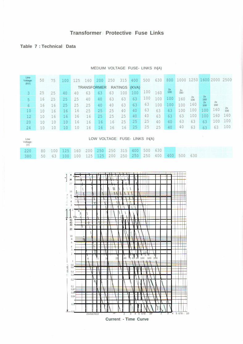
Transformer Protective Fuse Links
Table 7 : Technical Data
MEDUIM VOLTAGE FUSE- LINKS IN(A)
LineVoltage 50 75 100 125 160 200 250 315 400 500 630 800 1000 1250 1600 2000 2500
(KV)
TRANSFORMER RATINGS (KVA)2x 2x3 25 25 40 40 63 63 63 100 100 100 160 100 160
5 16 25 25 25 40 40 63 63 63 100 100 100 160 2x 2x100 160
16 25 63 63 100 160 2x 2x6 16 25 25 40 40 63 100 100 100 160
10 10 16 16 16 25 25 25 40 40 63 63 63 100 100 100 160 2x100
12 10 16 16 16 16 25 25 25 40 40 63 63 63 100 100 160 16020 10 10 10 16 16 16 16 25 25 25 40 40 63 63 63 100 10024 10 10 10 10 16 16 16 16 25 25 25 40 40 63 63 63 100
Low LOW VOLTAGE FUSE- LINKS IN(A)Voltage
(V)
220 80 100 125 160 200 250 250 315 400 500 630380 50 63 100 100 125 125 200 250 250 250 400 400 500 630
2 3 4 5 678 10·2 3 4 5 678 10234567810
\ \ \ \
\ , , \ I
\ \ \ \\ \ \ \ \
T \ \ \\ \ ,\ \ \ \-; \ \ \ \ \ \ \,
T \ \ \\ \ \
"\ \\ 1\ i\ \
I1\ \T \ \ 1\ 125 \
"6 10 16 25 40 ff) 63 00 100 100 200
\ \\
\ \ \ \
'\ \ \ \\\ \ \
\\\ \ \ \ \,
1\, \ 1\\.\ \1\ \ ~
'" n30,01
0,Cl2
1086
43
2
0,10,000,000,04
I'" 0,8-g 0,6
8 0,4~ 0,3
0,2
-] :~3020
10'" 8; 6.: 4~ 3
112
m
Current - Time Curve
Standard AccessoriesPart Qty
No No
1 12 43 34 35 1
6 17 1
8 29 1
10111213
parts
Rating plate on LV sideLV terminals, bushings according to DIN 42530HV terminals, bushings according to DIN 42531Earthing terminals on tank opposite sides and on coverThermometer poket DIN 42554Off - Circuit tap changerDraining and sampling device DIN 42551 for 100 to 1000 kVABall type valve for draining and sampling 1.5 from 1500 up to 5000 kVA.Lifting lugsAdapter for Buchholz relay 200 - 2500 kVAExpansion conservator with:1 Oil level indicator DIN 42569 on LV side (magnetic type without contacts)1 Filling device DIN 42553Silic gel breatherSampling device
Optional Accessories4 Bi-directional rollers DIN 42561
1 Mercury thermometer without contacts
1 Dial type thermometer with 2 pairs of adjustable contacts and re-settable max pointer
1 Double float Buchholz relay DIN 42566 DR
3 Arcing horns on HV bushings for outdoor installation
1 DGPT2 : Detecting and Monitoring of gases, pressure and temperature.
1 ABB -Standard Cable End Box ( Ip 54) for LV side.
1 ABB -Standard Cable End Box ( Ip 54) for HV side.
1 Pressure relief device.
1 Pressure relief device with contacts.
Standards:The transformers comply with the requirements of the following standards:IEC 76 Part 1-5 Power TransformersIEC 354 Loading Guide for Oil Immersed TransformersIEC 296 Specifications for Mineral Insulating Oil for Transformers and Switch GearIEC 137 Bushings
Ambient Temperature and Temperature Rise
•The standard transformers are designed for the fall wing :Ambient temperature of cooling air maximumTemperature rise of top oilTemperature rise of windings
4YC:55 K60K
For higher ambient temperatures ABB can offer optional designs with Lower temperature risethan mentioned above :
•The Low Losses transformers are designed for the following:Max. ambient temperature of cooling airTemperature rise of top oilTemperature rise of winding .
45°C45 K55 K
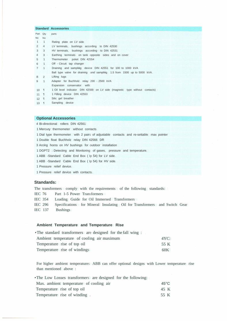
Technical InformationTable 1 :
Common Data:
7512517020
IEC7650Dyn11
5560ONAN
10.5, 11,22,330.4+ -2 x 2,5
HZ
kVkV
%
KK
kVkVkVkV
Top OilAverage WindingNatural CoolingFour OptionsAt No - Load
Off - Circuit Tap changer,S PositionsCopper conductors
Primary Winding Voltage 10.5 or 11kVPrimary Winding, Voltage 22 kV
Primary Winding, Voltage 36Secondary Winding, Voltage 0.4 kV
Three phase, Oil Immersed Distribution Transformers with Conservator, for Continuous Servicefor Indoor or Outdoor Installation.StandardFrequencyConnection and Vector Group
Max. Temperature Rise
Type of CoolingHigh Voltage RatingLow Voltage RatingHV TappingsWindings
Impulse Voltage Insulation LevelPeak value
Table 2
Rated PowerStandard Designs Low losses Designs
Short circuitKVA No load losses load losses @75 'C No load losses load losses @75 'C Impedance
Watt Watt Watt Watt %50 210 1100 168 820 4
100 320 1730 270 1420 4200 540 3250 455 2370 4300 720 5000 575 3580 4500 930 7500 700 5125 4630 1150 7800 825 6050 4.5800 1400 11000 1015 7235 4.51000 1650 12800 1220 8880 51250 1800 14000 1500 11000 5.751500 2400 15500 1785 13000 61600 2400 17700 1950 14000 6.42000 2800 21000 2735 14800 6.52500 3400 25000 3400 20000 6.53000 3800 30000 6.55000 6500 33500 5000 35000 7.15
Optional and Special Designs:
Optional and Special Designs may be offered on request such as :
· Compact design 1000 KVA occupies same space for 500 KVA standard transformer.
· Compact design 1500 KVA occupies same space for 1000 KVAstandard transformer.
· Off-circuit tap changer, 7 positions for voltage 22 kV + 2 x 2.5 % - 4 x 2.5% and 6 positions for voltage
11kV + 2 x 2.5% - 3 x 2.5%
· Transformers with reduced load losses and reduced temperature rise
· Other diffrent power ratings as 63, 160,250,400 and 750 kVA can be manufactured upon request.
· Transformers with Dual voltage in HV side as 22-11 kV or 11-5.5 kV can be manufactured upon request.
· Transformers equipped with on load tab changer OLTC , ratings 1000 and 1500 kVA up to 24 kV and 17 positions
+ 4 x 2 % - 12 x 2 % . can be manfuctured upon request.
· Air filled cable end boxes for LV and HV sides up to 24 kV.
· Transformers with 60 Hz and LV voltages up to 1.1 kV upon request.
· Hermetically sealed transformers completely filled with oil can be manufactured upon request
· Rectifier transformers upon request.
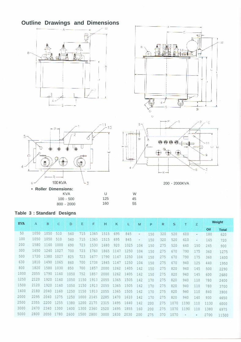
Outline Drawings and Dimensions12
8
8
A
I
12
4
6 200 - 2000KVA• Roller Dimensions:
KVA U W100 - 500 125 45800 - 2000 160 55
Table 3 : Standard Designs
KVA A B C D E F H K L M P R S T ZWeight
Oil Total50 1050 1050 510 560 715 1365 1515 695 845 150 320 520 610 180 620100 1050 1050 510 560 715 1365 1515 695 845 150 320 520 610 165 720200 1580 1160 1000 690 723 1530 1680 920 1025 104 150 275 520 640 150 245 900300 1650 1240 1027 700 723 1760 1865 1147 1250 104 150 275 670 790 175 360 1275500 1720 1380 1027 825 723 1677 1790 1147 1250 104 150 275 670 790 175 360 1600630 1810 1490 1065 860 700 1738 1845 1147 1250 104 150 275 670 940 125 440 1950800 1820 1580 1030 850 700 1857 2000 1262 1405 142 150 275 820 940 145 500 22901000 2055 1790 1160 1050 752 1857 2000 1262 1405 142 150 275 820 940 145 600 26801250 2120 1920 1160 1050 1150 1913 2055 1365 1505 142 170 275 820 940 110 780 24001500 2120 1920 1160 1050 1150 1913 2055 1365 1505 142 170 275 820 940 110 780 37001600 2180 2040 1160 1250 1150 1913 2055 1365 1505 142 170 275 820 940 110 840 39002000 2295 2040 1275 1250 1000 2145 2285 1470 1610 142 170 275 820 940 140 930 46502500 2355 2200 1255 1380 1200 2175 2315 1495 1640 142 200 275 1070 1190 110 1130 60003000 2470 2340 1300 1400 1300 2360 2520 1695 1855 160 200 275 1070 1190 110 1380 69755000 2800 2050 1780 2600 1500 2800 3000 1830 2030 200 275 370 1070 2700 11500
LO l~CXJLOLO nLOCXJ J ~»~~N..----N..----
DT 20NF/250 DT 20NF/250For outdoor For indoor
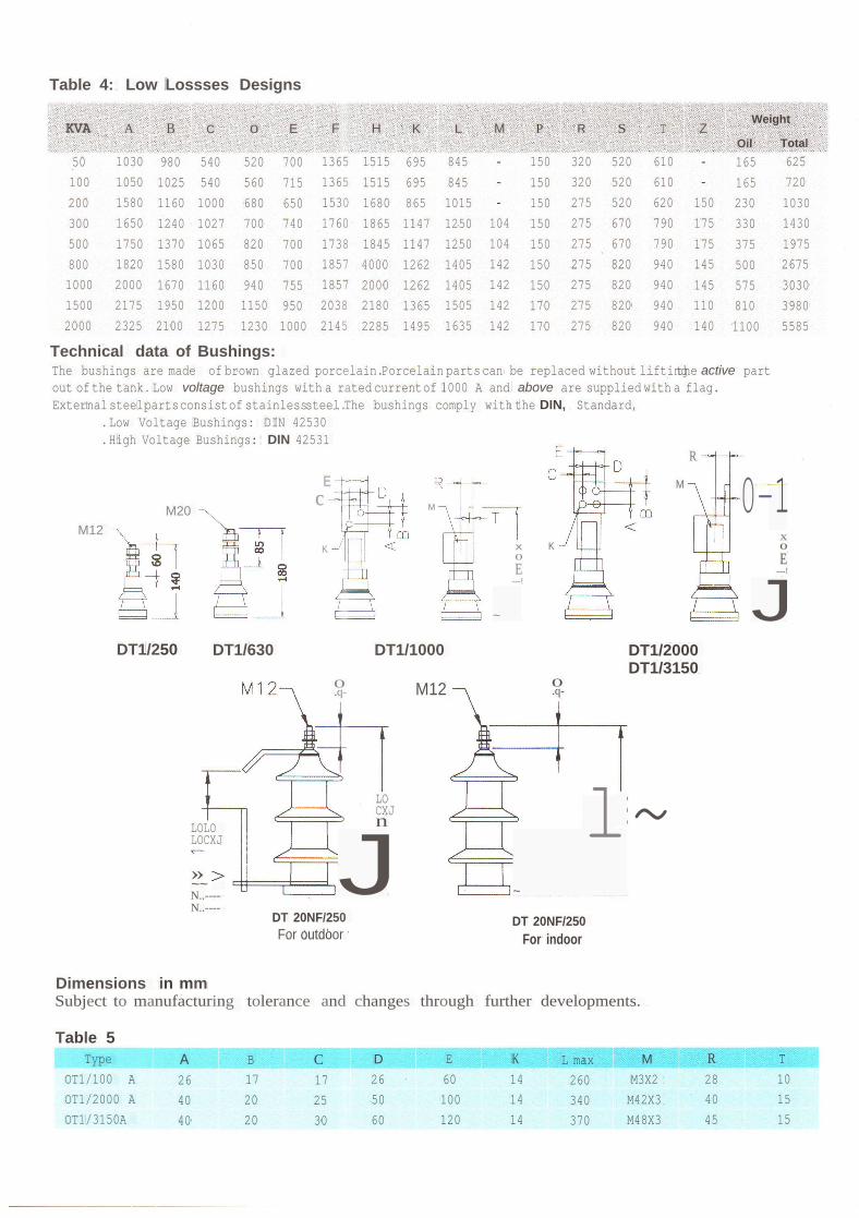
Table 4: Low Lossses Designs
KVA A B C 0 E F H K L M P R S T ZWeight
Oil Total50 1030 980 540 520 700 1365 1515 695 845 150 320 520 610 165 625100 1050 1025 540 560 715 1365 1515 695 845 150 320 520 610 165 720200 1580 1160 1000 680 650 1530 1680 865 1015 150 275 520 620 150 230 1030300 1650 1240 1027 700 740 1760 1865 1147 1250 104 150 275 670 790 175 330 1430500 1750 1370 1065 820 700 1738 1845 1147 1250 104 150 275 670 790 175 375 1975800 1820 1580 1030 850 700 1857 4000 1262 1405 142 150 275 820 940 145 500 26751000 2000 1670 1160 940 755 1857 2000 1262 1405 142 150 275 820 940 145 575 30301500 2175 1950 1200 1150 950 2038 2180 1365 1505 142 170 275 820 940 110 810 39802000 2325 2100 1275 1230 1000 2145 2285 1495 1635 142 170 275 820 940 140 1100 5585
Technical data of Bushings:The bushings are made of brown glazed porcelain.Porcelain parts can be replaced without liftingthe active partout of the tank. Low voltage bushings with a rated currentof 1000 A and above are supplied with a flag.External steelpartsconsistof stainlesssteel.The bushings comply with the DIN, Standard,
.Low Voltage Bushings: DIN 42530
.High Voltage Bushings: DIN 42531R
E M 0-1M20c M
M12 xK x K 0
0 EE ---!---! J~
DT1/250 DT1/630 DT1/1000 DT1/2000DT1/3150
0 M12 0.q- .q-
Dimensions in mmSubject to manufacturing tolerance and changes through further developments.
Table 5Type A B C D E K L max M R T
OT1/100 A 26 17 17 26 60 14 260 M3X2 28 10OT1/2000 A 40 20 25 50 100 14 340 M42X3 40 15OT1/3150A 40 20 30 60 120 14 370 M48X3 45 15


