Embed Size (px)
Citation preview
CollegePhysics B
Transformers
Electro-magnetism
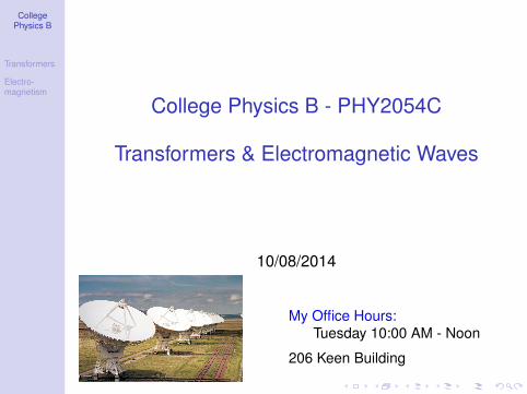
College Physics B - PHY2054C
Transformers & Electromagnetic Waves
10/08/2014
My Office Hours:
Tuesday 10:00 AM - Noon
206 Keen Building
CollegePhysics B
Transformers
Electro-magnetism
PHY2054C
Second Mini-Exam next week on Wednesday!!
• Location: UPL 101, 10:10 - 11:00 AM
• Exam on chapters 22, 23 & 25 (HW 5, 6, 7 & 8)
• Magnetic forces & fields (right-hand rules)
• Induction, Faraday’s Law, Lenz’s Law
• Generator & Transformers
• Eletromagnetic Spectrum & Waves
• Equation sheet will be provided.
• Do not forget to bring your student ID!
CollegePhysics B
Transformers
Electro-magnetism
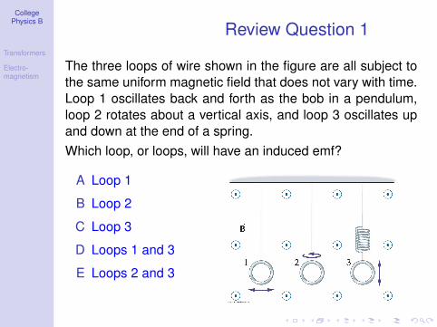
Review Question 1
The three loops of wire shown in the figure are all subject to
the same uniform magnetic field that does not vary with time.
Loop 1 oscillates back and forth as the bob in a pendulum,
loop 2 rotates about a vertical axis, and loop 3 oscillates up
and down at the end of a spring.
Which loop, or loops, will have an induced emf?
A Loop 1
B Loop 2
C Loop 3
D Loops 1 and 3
E Loops 2 and 3
CollegePhysics B
Transformers
Electro-magnetism
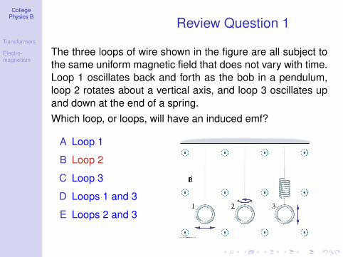
Review Question 1
The three loops of wire shown in the figure are all subject to
the same uniform magnetic field that does not vary with time.
Loop 1 oscillates back and forth as the bob in a pendulum,
loop 2 rotates about a vertical axis, and loop 3 oscillates up
and down at the end of a spring.
Which loop, or loops, will have an induced emf?
A Loop 1
B Loop 2
C Loop 3
D Loops 1 and 3
E Loops 2 and 3
CollegePhysics B
Transformers
Electro-magnetism
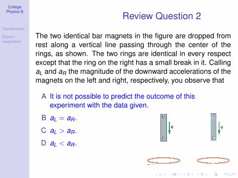
Review Question 2
The two identical bar magnets in the figure are dropped from
rest along a vertical line passing through the center of the
rings, as shown. The two rings are identical in every respect
except that the ring on the right has a small break in it. Calling
aL and aR the magnitude of the downward accelerations of the
magnets on the left and right, respectively, you observe that
A It is not possible to predict the outcome of this
experiment with the data given.
B aL = aR.
C aL > aR.
D aL < aR.
CollegePhysics B
Transformers
Electro-magnetism
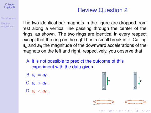
Review Question 2
The two identical bar magnets in the figure are dropped from
rest along a vertical line passing through the center of the
rings, as shown. The two rings are identical in every respect
except that the ring on the right has a small break in it. Calling
aL and aR the magnitude of the downward accelerations of the
magnets on the left and right, respectively, you observe that
A It is not possible to predict the outcome of this
experiment with the data given.
B aL = aR.
C aL > aR.
D aL < aR.
CollegePhysics B
Transformers
Electro-magnetism
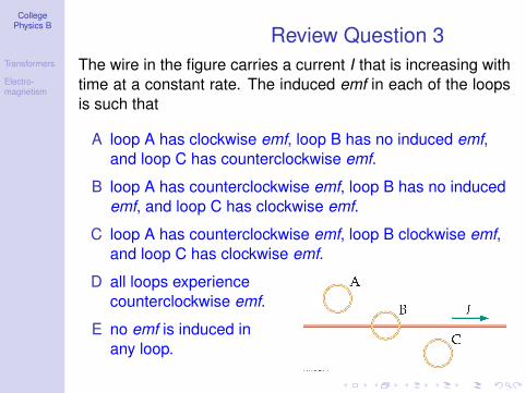
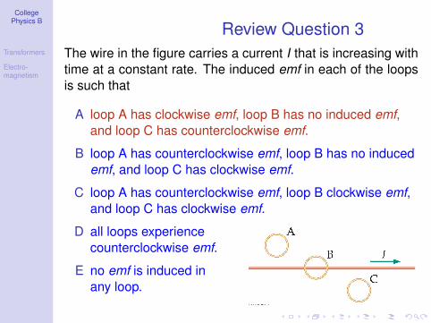
Review Question 3
The wire in the figure carries a current I that is increasing with
time at a constant rate. The induced emf in each of the loops
is such that
A loop A has clockwise emf, loop B has no induced emf,
and loop C has counterclockwise emf.
B loop A has counterclockwise emf, loop B has no induced
emf, and loop C has clockwise emf.
C loop A has counterclockwise emf, loop B clockwise emf,
and loop C has clockwise emf.
D all loops experience
counterclockwise emf.
E no emf is induced in
any loop.
CollegePhysics B
Transformers
Electro-magnetism
Outline
1 Transformers
2 Electromagnetism
CollegePhysics B
Transformers
Electro-magnetism
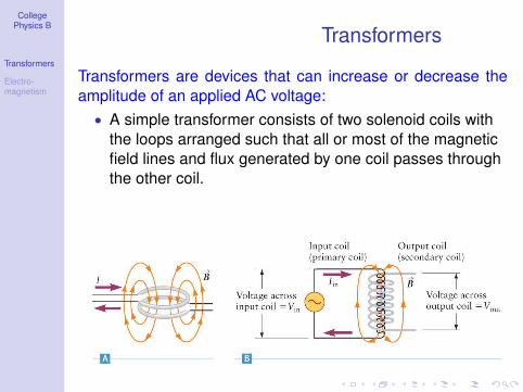
Transformers
Transformers are devices that can increase or decrease the
amplitude of an applied AC voltage:
• A simple transformer consists of two solenoid coils with
the loops arranged such that all or most of the magnetic
field lines and flux generated by one coil passes through
the other coil.
CollegePhysics B
Transformers
Electro-magnetism
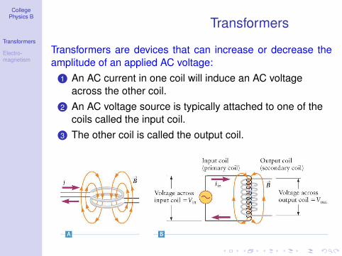
Transformers
Transformers are devices that can increase or decrease the
amplitude of an applied AC voltage:
1 An AC current in one coil will induce an AC voltage
across the other coil.
2 An AC voltage source is typically attached to one of the
coils called the input coil.
3 The other coil is called the output coil.
CollegePhysics B
Transformers
Electro-magnetism
Transformers
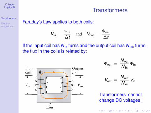
Faraday’s Law applies to both coils:
Vin =Φin
∆tand Vout =
Φout
∆t
If the input coil has N in turns and the output coil has N out turns,
the flux in the coils is related by:
Φout =N out
N in
Φin
Vout =N out
N in
Vin
Transformers cannot
change DC voltages!
CollegePhysics B
Transformers
Electro-magnetism
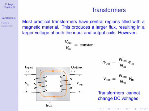
Transformers
Most practical transformers have central regions filled with a
magnetic material. This produces a larger flux, resulting in a
larger voltage at both the input and output coils. However:
Vout
Vin
= constant
Φout =N out
N in
Φin
Vout =N out
N in
Vin
Transformers cannot
change DC voltages!
CollegePhysics B
Transformers
Electro-magnetism
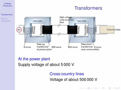
Transformers
At the power plant
Supply voltage of about 5 000 V
Cross-country lines
Voltage of about 500 000 V
CollegePhysics B
Transformers
Electro-magnetism
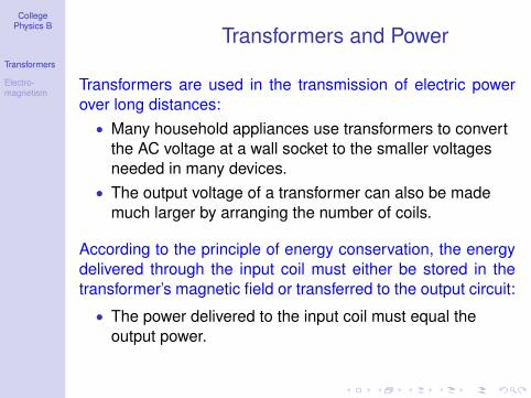
Transformers and Power
Transformers are used in the transmission of electric power
over long distances:
• Many household appliances use transformers to convert
the AC voltage at a wall socket to the smaller voltages
needed in many devices.
• The output voltage of a transformer can also be made
much larger by arranging the number of coils.
According to the principle of energy conservation, the energy
delivered through the input coil must either be stored in the
transformer’s magnetic field or transferred to the output circuit:
• The power delivered to the input coil must equal the
output power.
CollegePhysics B
Transformers
Electro-magnetism
Transformers and Power
According to the principle of energy conservation, the energy
delivered through the input coil must either be stored in the
transformer’s magnetic field or transferred to the output circuit:
• Since P = V I, if Vout is greater than Vin, then I out must be
smaller than I in.
• Pin = Pout only in ideal transformers
In real transformers, the coils always have a small
electrical resistance causing some power dissipation.
For a real transformer, the output power is always
less than the input power.
• Power carried by the power line:
Pavg = Vrms I rms
CollegePhysics B
Transformers
Electro-magnetism
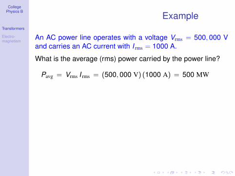
Example
An AC power line operates with a voltage Vrms = 500, 000 V
and carries an AC current with I rms = 1000 A.
What is the average (rms) power carried by the power line?
Pavg = Vrms I rms = (500, 000 V) (1000 A) = 500 MW
CollegePhysics B
Transformers
Electro-magnetism
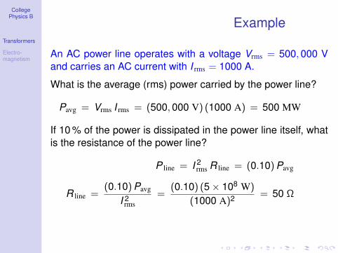
Example
An AC power line operates with a voltage Vrms = 500, 000 V
and carries an AC current with I rms = 1000 A.
What is the average (rms) power carried by the power line?
Pavg = Vrms I rms = (500, 000 V) (1000 A) = 500 MW
If 10 % of the power is dissipated in the power line itself, what
is the resistance of the power line?
P line = I2rms R line = (0.10)Pavg
R line =(0.10)Pavg
I 2rms
=(0.10) (5 × 10⁸ W)
(1000 A)2= 50 Ω
CollegePhysics B
Transformers
Electro-magnetism
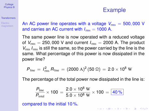
Example
An AC power line operates with a voltage Vrms = 500, 000 V
and carries an AC current with I rms = 1000 A.
The same power line is now operated with a reduced voltage
of Vrms = 250, 000 V and current I rms = 2000 A. The product
Vrms I rms is still the same, so the power carried by the line is the
same. What percentage of this power is now dissipated in the
power line?
P line = I2rms R line = (2000 A)2 (50 Ω) = 2.0 × 10⁸ W
The percentage of the total power now dissipated in the line is:
Pline
Ptotal
× 100 =2.0 × 10⁸ W
5.0 × 108 W× 100 = 40 %
compared to the initial 10 %.
CollegePhysics B
Transformers
Electro-magnetism
Outline
1 Transformers
2 Electromagnetism
CollegePhysics B
Transformers
Electro-magnetism
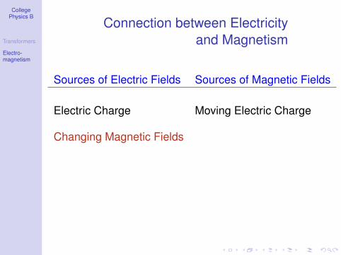
Connection between Electricity
and Magnetism
Sources of Electric Fields Sources of Magnetic Fields
Electric Charge
CollegePhysics B
Transformers
Electro-magnetism
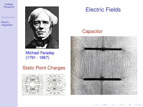
Electric Fields
Michael Faraday
(1791 - 1867)
Capacitor
Static Point Charges
CollegePhysics B
Transformers
Electro-magnetism
Connection between Electricity
and Magnetism
Sources of Electric Fields Sources of Magnetic Fields
Electric Charge Moving Electric Charge
CollegePhysics B
Transformers
Electro-magnetism
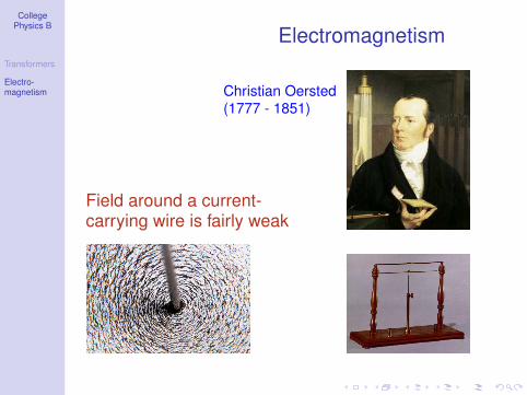
Electromagnetism
Christian Oersted
(1777 - 1851)
Field around a current-carrying wire is fairly weak
CollegePhysics B
Transformers
Electro-magnetism
Connection between Electricity
and Magnetism
Sources of Electric Fields Sources of Magnetic Fields
Electric Charge Moving Electric Charge
Changing Magnetic Fields
CollegePhysics B
Transformers
Electro-magnetism
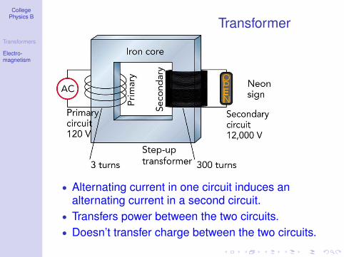
Transformer
• Alternating current in one circuit induces analternating current in a second circuit.
• Transfers power between the two circuits.
• Doesn’t transfer charge between the two circuits.
CollegePhysics B
Transformers
Electro-magnetism
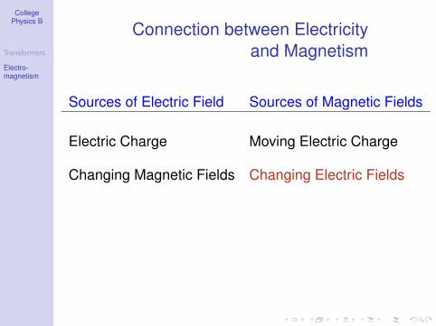
Connection between Electricity
and Magnetism
Sources of Electric Field Sources of Magnetic Fields
Electric Charge Moving Electric Charge
Changing Magnetic Fields Changing Electric Fields
CollegePhysics B
Transformers
Electro-magnetism
Connection between Electricity
and Magnetism
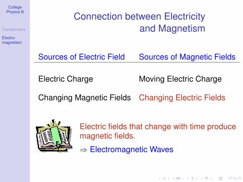
Sources of Electric Field Sources of Magnetic Fields
Electric Charge Moving Electric Charge
Changing Magnetic Fields Changing Electric Fields
Electric fields that change with time producemagnetic fields.
⇒ Electromagnetic Waves
CollegePhysics B
Transformers
Electro-magnetism
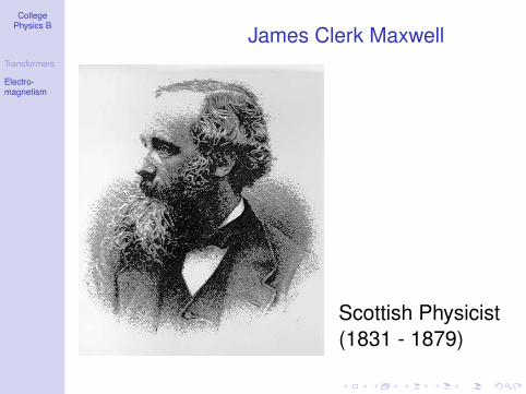
James Clerk Maxwell
Scottish Physicist
(1831 - 1879)
CollegePhysics B
Transformers
Electro-magnetism
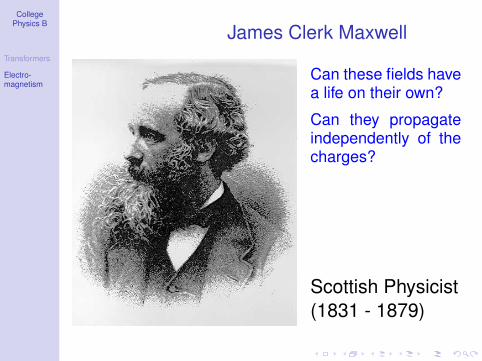
James Clerk Maxwell
Can these fields havea life on their own?
Can they propagateindependently of thecharges?
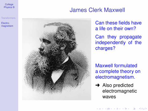
Scottish Physicist
(1831 - 1879)
CollegePhysics B
Transformers
Electro-magnetism
James Clerk Maxwell
Can these fields havea life on their own?
Can they propagateindependently of thecharges?
Maxwell formulateda complete theory onelectromagnetism.
Also predictedelectromagneticwaves
CollegePhysics B
Transformers
Electro-magnetism
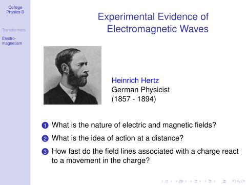
Experimental Evidence of
Electromagnetic Waves
Heinrich Hertz
German Physicist
(1857 - 1894)
1 What is the nature of electric and magnetic fields?
2 What is the idea of action at a distance?
3 How fast do the field lines associated with a charge react
to a movement in the charge?
CollegePhysics B
Transformers
Electro-magnetism
The History of Wireless Communication
1865 Prediction of radio waves (James Clerk Maxwell)
1886 Experimental evidence of radio waves
(Heinrich Hertz)
1895 Signal transmission over 10 m
1899 Signal transmission over the English Channel
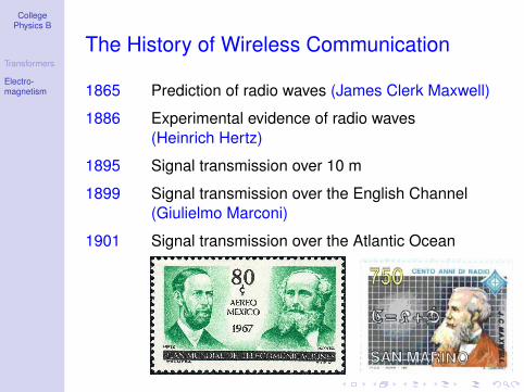
(Giulielmo Marconi)
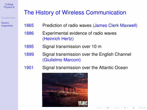
1901 Signal transmission over the Atlantic Ocean
CollegePhysics B
Transformers
Electro-magnetism
The History of Wireless Communication
1865 Prediction of radio waves (James Clerk Maxwell)
1886 Experimental evidence of radio waves
(Heinrich Hertz)
1895 Signal transmission over 10 m
1899 Signal transmission over the English Channel
(Giulielmo Marconi)
1901 Signal transmission over the Atlantic Ocean


