Embed Size (px)
Citation preview
KNPC Clean Fuels Project 2020 FEED Update Phase EI S Rev 2 DNV ENERGY
12.3.6 Storm Water Management
Storm water that falls within the CFP process equipment areas wi ll be segregated from storm water that falls outside these areas (such as on road surfaces as well as unpaved or grass covered surfaces, etc.). All storm water within CFP process areas as well as floor wash water and fire water runoff from paved surfaces will be gravity drained via the AOC Drain System.
Clean CFP storm water falling outside process areas from MAA (OSBL) is released into an existing concrete lined ditch along the south side of MAA and winds through the refinery to make its way to a wadi near the southeast corner of MAA (KNPC currently use this wadi to receive clean storm water from existing areas of MAA).
Clean storm water runoff from MAB areas and roadways outside paved process areas is collected in an oil catcher and pumped to the Gulf.
The MAA will discharge approximately 14,600 m3/hr of clean OSBL storm water during the infrequent rainfall events. An estimated 40,000 m3/hr storm water will originate from OSBL non-process areas and roads at MAB during the infrequent rainfall events.
12.3.7 Capacity, Rates and Composition at CFP WWT Facilities
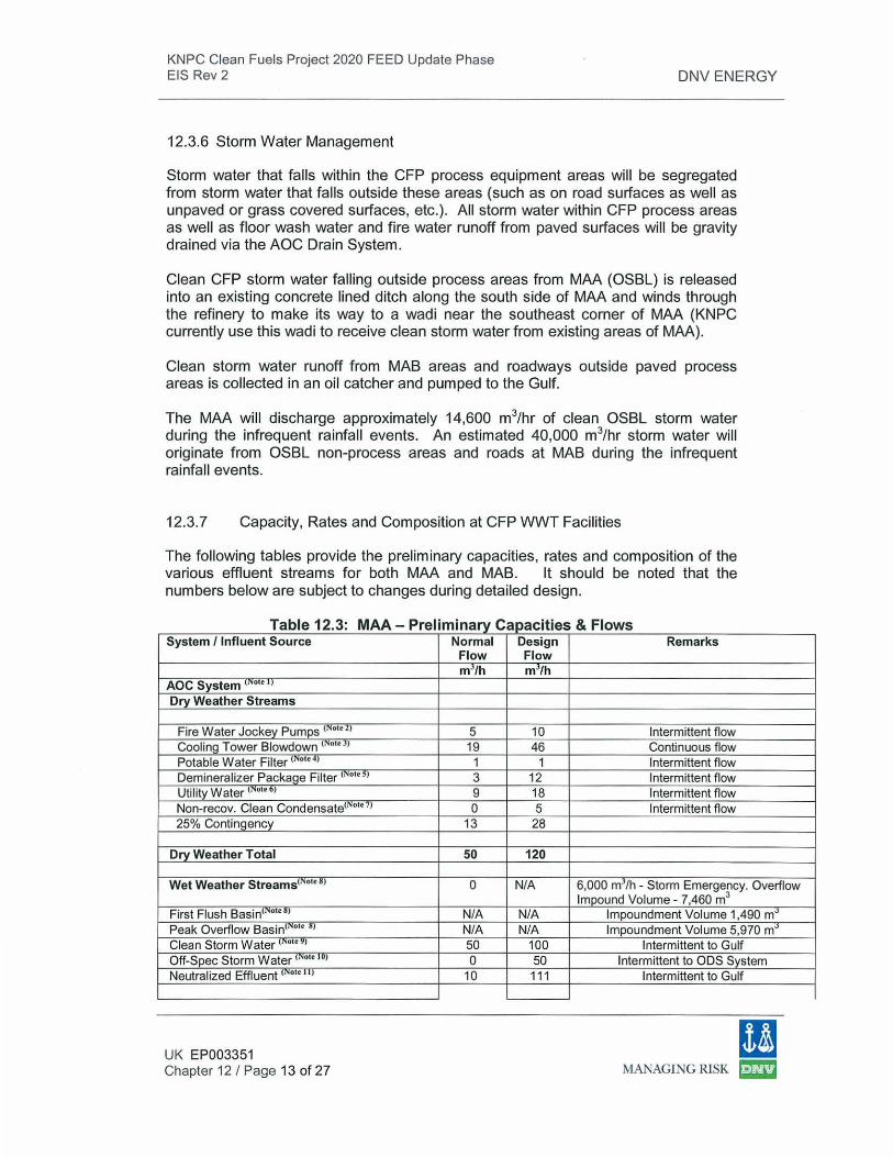
The fo llowing tables provide the preliminary capacities, rates and composition of the various effluent streams for both MAA and MAB. lt should be noted that the numbers below are subject to changes during detai led design.
a e - re 1mmary T bl 12 3 MAA P I' . c "f & Fl apac1 1es ows System / Influent Source Normal Design Remarks
Flow Flow mJ/h m3/h
AOC System tN••• ' ' Dry Weather Streams
Fire Water Jockey Pumps < ••u, 5 10 Intermittent flow Cooling Tower Blowdown '""'.'' 19 46 Continuous flow Potable Water Filter<,..., .. , 1 1 Intermittent flow Demineralizer Package Filter <Notes) 3 12 Intermittent flow Utility Water (Note6J 9 18 Intermittent flow Non-recov. Clean Condensate<NotnJ 0 5 Intermittent flow 25% Contingency 13 28
Dry Weather Total 50 120
Wet Weather Streams<Not .. , 0 N/A 6,000 mJ/h - Storm Emergency. Overflow Impound Volume - 7,460 m3
First Flush Basin' ••••J N/A N/A Impoundment Volume 1,490 m~ Peak Overflow Basin<"'••• •l N/A N/A Impoundment Volume 5,970 m~ Clean Storm Water <• .,.,, 50 100 Intermittent to Gulf Off-Spec Storm Water ( oi<IUJ 0 50 Intermittent to ODS System Neutralized Effluent (Note ttl 10 111 Intermittent to Gulf
UK EP003351 Chapter 12 I Page 13 of 27
I! MANAGING RlSK ~
KNPC Clean Fuels Project 2020 FEED Update Phase EIS Rev 2
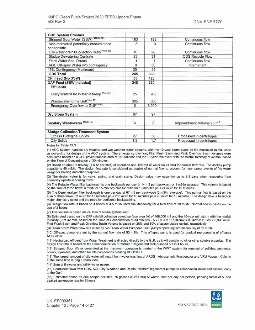
ODS System Streams Stripped Sour Water (SSW) v·ouoe "' 183 Non-recovered potentially contaminated 3 condensate Oily water drains/Collection Hubs1
N o • l J J 10 Sludge Dewatering Centrate 23 Flare Water Seal Drums 1 AOC Off-spec Water w/o conting_ency 0 15% Contingency (Maximum) 30 ODS Total 245
CPI Feed (No SSW) 35 OAF Feed (SSW Included) 245
Effluents
Utility Water/Fire Water Makeup (Notet4J 25
Wastewater to the Gulf'' ••• '5' 305 Emergency_ Overflow to GulfiN••• ~J 0
Dry Slops System 97
Sanitary Wastewater 1 ••• '"' 4
Sludge Collection/Treatment System Excess Biological Solids 27 Oily Solids 1.3
Notes for Table 12.3:
DNV ENERGY
183 Continuous flow 3 Continuous flow
20 Continuous flow 31 ODS Recycle Flow
1 Continuous flow 50 Intermittent 42
330 120 330
208
560 6,000
97
8 Impoundment Volume 28 mJ
36 Processed in centrifuges 1.7 Processed in centrifuges
(1) AOC System handles dry-weather and wet-weather water streams, with the 10-year storm event as the maximum rainfall case as governing for design of the AOC system. The emergency overflow, First Flush Basin and Peak Overflow Basin volumes were calculated based on a CFP paved process area of 168,000 m2 and the 10-year rain event with the rainfall Intensity of 42 mm, based on the Time of Concentration of 30 minutes. (2) Based on about 5 hrs/day (1 .5 hr per shift) of operation and 120m3 of water (in 24 hrs) for normal flow rate. The Jockey pump capacity is 40 m3/h. The design flow rate is considered as double of normal flow to account for non-normal events of fire water usage for training and other purposes.
(3) The design value is for valve, piping, and drain sizing. Design value may occur for up to 2-3 days when recovering from chemistry upsets in cooling tower.
(4) The Potable Water filter backwash is one backwash per day at 14m3 per backwash or 1 m3/hr average. This volume is based on the sum of three flows: 6 m3/h for 15 minutes plus 52 m3/h for 10 minutes plus 24 m3/h for 10 minutes. (5) The Demineralizer filter backwash is one per day at 67 m3 per backwash (3 m3/h average). This normal flow is based on the sum of three flows: 33 m3/h for 15 minutes plus 265 m3/h for 10 minutes plus 90 m3/h for 10 minutes. The design flow is based on major chemistry upset and the need for additional backwashing.
(6) Design flow rate is based on 4 hoses at 4.5 m3/h used simultaneously for a total flow of 18m3/h. Normal flow is based on the use of 2 hoses. (7) This volume is based on 2% loss of steam system load. (8) Estimated based on the CFP rainfall collection paved surface area (A) of 168,000 m2 and the 10-year rain storm with the rainfall Intensity (I) of 42 mm, based on the Time of Concentration of 30 minutes- A xI x C = 167,943m2 x 0.042m/h x 0.85 = 5,996 m3/h. First Flush Basin and Peak Overflow Basin Volume is based on 20% and 80% of accumulated rainfall, respectively.
(9) Clean Storm Water flow rate is set by two Clean Water Pumpout Basin pumps operating simultaneously at 50m3/h. (10) Off-spec pump rate set by the normal flow rate of 50 m3/h. This off-spec pump is used for gradual reprocessing of off-spec AOC water. (11) Neutralized effluent from Water Treatment is directed directly to the Gulf, as it will contain no oil or other soluble organics. The design flow rate is based on the Demineralization I Polisher I Regenerant tank pumped out in 4 hours.
(12) Stripped Sour Water generated at the maximum operation is treated in the WWT system for removal of sulfides, ammonia, phenol, cyanides, and other soluble compounds creating BOO/COD. (13) The largest amount of oily water will result from water washing of ARDS Atmospheric Fractionator and VRU Vacuum Column at the same time during turnarounds. (14) Sum of firewater and utility water usage.
(15) Combined flows from ODS, AOC Dry Weather. and Demin/Polisher/Regenerant pumps to Observation Basin and consequently to the Gulf.
(16) Estimated based on 356 people per shift, 75 gallons (0.284 m3) of water used per day per person, peaking factor of 5, and peaked generation rate for 5 hours.
UK EP003351 Chapter 12/ Page 14 of 27
11 MANAGING RISK ~
KNPC Clean Fuels Project 2020 FEED Update Phase EIS Rev 2
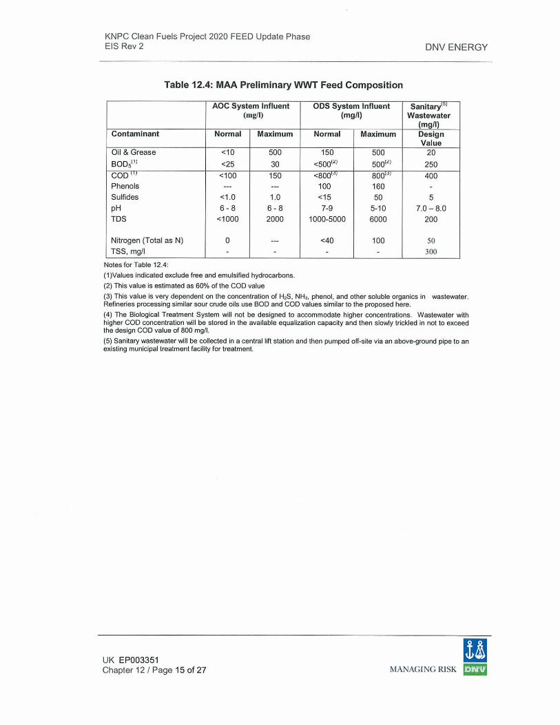
Table 12.4: MAA Preliminary WWT Feed Composition
AOC System Influent (mg/1)
Contaminant Normal Maximum
Oil & Grease <10 500 BODslll <25 30 COD 1 ' 1 <100 150 Phenols --- ---Sulfides <1.0 1.0 pH 6-8 6-8 TDS <1000 2000
Nitrogen (Total as N) 0 ---TSS, mg/1 - -
Notes for Table 12.4:
(1)Values indicated exclude free and emulsified hydrocarbons.
(2) This value is estimated as 60% of the COD value
ODS System Influent (mg/1)
Normal Maximum
150 500 <500\l) 500\l)
<8001" 1 8001" 1
100 160 <15 50 7-9 5-10
1000-5000 6000
<40 100 - -
DNV ENERGY
Sanitary101
Wastewater (mg/1) Design Value
20 250 400 -5
7.0-8.0 200
50 300
(3) This value is very dependent on the concentration of H;?8, NH3, phenol, and other soluble organics in wastewater. Refineries processing similar sour crude oils use BOO and COD values similar to the proposed here.
(4) The Biological Treatment System will not be designed to accommodate higher concentrations. Wastewater with higher COD concentration will be stored in the available equalization capacity and then slowly trickled in not to exceed the design COD value of 800 mg/1.
(5) Sanitary wastewater will be collected in a central lift station and then pumped off-site via an above-ground pipe to an existing municipal treatment facility for treatment.
UK EP003351 Chapter 12 I Page 15 of 27
m MANAGING RISK ~
KNP C Clean Fuels Project 2020 FEED Update Phase EIS Rev 2 DNV ENERGY
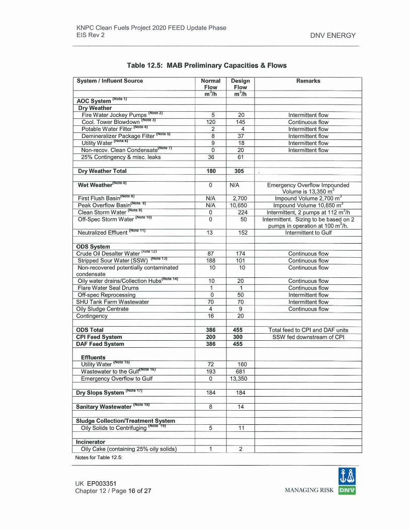
Table 12.5: MAB Preliminary Capacities & Flows
System /Influent Source Normal Design Remarks Flow Flow m~/h m~/h
AOC System 1"
0 •
11
Dry Weather Fire Water Jockey Pumps '"0'"~' 5 20 Intermittent flow Cool. Tower Blowdown 1" 0 e., 120 145 Continuous flow Potable Water Filter 1"
0 0" 1 2 4 Intermittent flow
Demineralizer Package Filter 1"0
• "1 8 37 Intermittent flow
Utility Water '" 0 • "1 9 18 Intermittent flow
Non-recov. Clean Condensate'" 0 • '
1 0 20 Intermittent flow 25% Contingency & mise. leaks 36 61
Dry Weather Total 180 305
Wet Weather'" o • " 1 0 N/A Emergency Overflow Impounded Volume is 13,350 m3
First Flush Basin'"0 e "1 N/A 2,700 Impound Volume 2,700 m• Peak Overflow Basin1No • "1 N/A 10,650 Impound Volume 10,650 m• Clean Storm Water \NO e., 0 224 Intermittent, 2 pumps at 112 m•th Off-Spec Storm Water \NO e '"1 0 50 Intermittent. Sizing to be based on 2
pumps in operation at 100 m3/h. Neutralized Effluent 1" o • ''1 13 152 Intermittent to Gulf
ODS System Crude Oil Desalter Water no e ·~~ 87 174 Continuous flow Stripped Sour Water (SSW) '"u•• •• 1 188 101 Continuous flow Non-recovered potentially contaminated 10 10 Continuous flow
condensate Oily water drains/Collection Hubs1No •
141 10 20 Continuous flow Flare Water Seal Drums 1 1 Continuous flow Off-spec Reprocessing 0 50 Intermittent flow
SHU Tank Farm Wastewater 70 70 Intermittent flow Oily Sludge Centrate 4 9 Continuous flow Contingency 16 20
ODS Total 386 455 Total feed to CPI and OAF units CPI Feed System 200 300 SSW fed downstream of CPI OAF Feed System 386 455
Effluents Utility Water 1"
0'0
" 1 72 160 Wastewater to the Gulf\"0
'" '"' 193 681 Emerg_enc_y_ Overflow to Gulf 0 13,350
Dry Slops System 1"0
e 'I 184 184
Sanitary Wastewater 1" 0 • ' "1 8 14
Sludge Collection/Treatment System Oily Solids to Centrifuging 1"
0'" ••I 5 11
Incinerator Oily Cake (containing 25% oily solids) 1 2
Notes for Table 12.5:
UK EP003351 Chapter 12 I Page 16 of 27
!I MANAGING RISK I::II!3
KNPC Clean Fuels Project 2020 FEED Update Phase EIS Rev 2 DNV ENERGY
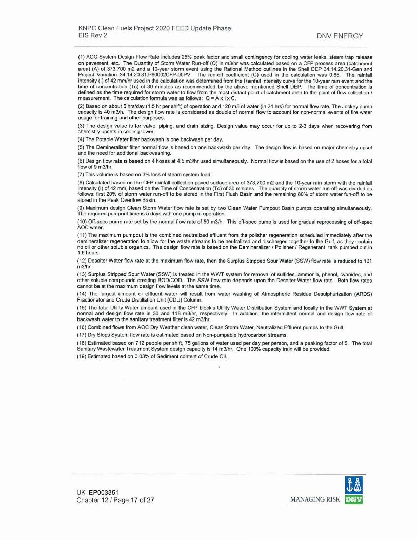
(1) AOC System Design Flow Rate includes 25% peak factor and small contingency for cooling water leaks, steam trap release on pavement, etc. The Quantity of Storm Water Run-off (Q) in m3/hr was calculated based on a CFP process area (catchment area) (A) of 373,700 m2 and a 10-year storm event using the Rational Method outlines in the Shell DEP 34.14.20.31-Gen and Project Variation 34. 14.20.31 .P60002CFP-OOPV. The run-off coefficient (C) used in the calculation was 0.85. The rainfall intensity (I) of 42 mm/hr used in the calculation was determined from the Rainfall Intensity curve for the 1 0-year rain event and the time of concentration (Tc) of 30 minutes as recommended by the above mentioned Shell DEP. The time of concentration is defined as the time required for storm water to flow from the most distant point of catchment area to the point of flow collection I measurement. The calculation formula was as follows: Q =A x I x C.
(2) Based on about 5 hrs/day (1.5 hr per shift) of operation and 120m3 of water (in 24 hrs) for normal flow rate. The Jockey pump capacity is 40 m3/h. The design flow rate is considered as double of normal flow to account for non-normal events of fire water usage for training and other purposes.
(3) The design value is for valve, piping, and drain sizing. Design value may occur for up to 2-3 days when recovering from chemistry upsets in cooling tower.
( 4) The Potable Water filter backwash is one backwash per day.
(5) The Demineralizer filter normal flow is based on one backwash per day. The design flow is based on major chemistry upset and the need for additional backwashing.
(6) Design flow rate is based on 4 hoses at 4.5 m3/hr used simultaneously. Normal flow is based on the use of 2 hoses for a total flow of 9 m3/hr.
(7) This volume is based on 3% loss of steam system load.
(8) Calculated based on the CFP rainfall collection paved surface area of 373,700 m2 and the 10-year rain storm with the rainfall Intensity (I) of 42 mm, based on the Time of Concentration (Tc) of 30 minutes. The quantity of storm water run-off was divided as follows: first 20% of storm water run-off to be stored in the First Flush Basin and the remaining 80% of storm water fun-off to be stored in the Peak Overflow Basin.
(9) Maximum design Clean Storm Water flow rate is set by two Clean Water Pumpout Basin pumps operating simultaneously. The required pumpout time is 5 days with one pump in operation.
(10) Off-spec pump rate set by the normal flow rate of 50m3/h. This off-spec pump is used for gradual reprocessing of off-spec AOCwater.
( 11) The maximum pumpout is the combined neutralized effluent from the polisher regeneration scheduled immediately after the demineralizer regeneration to allow for the waste streams to be neutralized and discharged together to the Gulf, as they contain no oil or other soluble organics. The design flow rate is based on the Demineralizer I Polisher I Regenerant tank pumped out in 1.6 hours.
(12) Desalter Water flow rate at the maximum flow rate, then the Surplus Stripped Sour Water (SSW) flow rate is reduced to 101 m3/hr.
(13) Surplus Stripped Sour Water (SSW) is treated in the WWT system for removal of sulfides, ammonia, phenol, cyanides, and other soluble compounds creating BOO/COD. The SSW flow rate depends upon the Desalter Water flow rate. Both flow rates cannot be at the maximum design flow levels at the same time.
(14) The largest amount of effluent water will result from water washing of Atmospheric Residue Desulphurization (ARDS) Fractionator and Crude Distillation Unit (CDU) Column.
(15) The total Utility Water amount used in the CFP block's Utility Water Distribution System and locally in the WWT System at normal and design flow rate is 30 and 118 m3/hr, respectively. In addition, the intermittent normal and design flow rate of backwash water to the sanitary treatment filter is 42 m3/hr.
(16) Combined flows from AOC Dry Weather clean water, Clean Storm Water, Neutralized Effluent pumps to the Gulf.
(17) Dry Slops System flow rate is estimated based on Non-pumpable hydrocarbon streams.
(18) Estimated based on 712 people per shift, 75 gallons of water used per day per person, and a peaking factor of 5. The total Sanitary Wastewater Treatment System design capacity is 14 m3/hr. One 100% capacity train will be provided.
(19) Estimated based on 0.03% of Sediment content of Crude Oil.
UK EP003351 Chapter 12 I Page 17 of 27
11 MANAGING RISK ~
KNPC Clean Fuels Project 2020 FEED Update Phase EIS Rev 2 DNV ENERGY
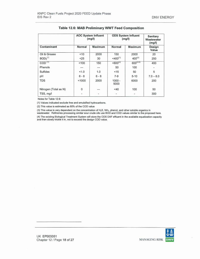
Table 12.6: MAB Preliminary WWT Feed Composition
AOC System Influent (mg/1)
Contaminant Normal Maximum
Oil & Grease <10 2000 BODsl1l <25 30
COD <100 150 Phenols --- ---Sulfides <1.0 1.0 pH 6-8 6-8 TDS <1000 2000
Nitrogen (Total as N) 0 ---TSS, mg/1 - -
Notes for Table 12.6:
(1) Values indicated exclude free and emulsified hydrocarbons.
(2) This value is estimated as 60% of the COD value
ODS System Influent (mg/1)
Normal Maximum
150 2000
<40011' 400(£)
<6001<1 6001~'q1
50 100 <15 50
7-9 5-10
1000- 6000 5000
<40 100
- -
Sanitary Wastewater
(mg/1)
Design Value
20 250
400
-5
7.0 - 8.0
200
50 300
(3) This value is very dependent on the concentration of H2S. NHJ, phenol , and other soluble organics in wastewater. Refineries processing similar sour crude oils use BOO and COD values similar to the proposed here.
(4) The existing Biological Treatment System will store the ODS OAF effluent in the available equalization capacity and then slowly trickle it in, not to exceed the design COD value.
11 UK EP003351 Chapter 12 I Page 18 of 27 MANAGING RISK ~
KNPC Clean Fuels Project 2020 FEED Update Phase EIS Rev 2
12.4 Water Conservation On-site During Operation
DNV ENERGY
Water conservation is a priority for KNPC. Therefore, the CFP project will implement technologies and operating practices to achieve a high degree of effluent reduction. Toward this intent, KNPC will endeavour to reduce wastewater generation and recycle I reuse all treated wastewater to the extent practica l. Several different methods will be used to conserve water including:
1. Collection and reuse of steam condensate as BFW. 2. Collection and reuse of boiler blowdown as makeup to the cooling tower. 3. Reuse of process stripped sour water as wash water. 4. Reuse of treated wastewater from equipment areas as utility water. 5. Reuse of treated wastewater from the utility water system for fire fighting
water (the first fill of firewater tanks will be from fresh water and thereafter the firewater tanks will be filled from treated wastewater).
6. Reuse of treated sanitary grey wastewater from the MAB facility as irrigation water for landscaping.
7. Use of packed-bed/rinse recycle technology for the water demineralization system which significantly reduces the volume of regeneration wastewater produced.
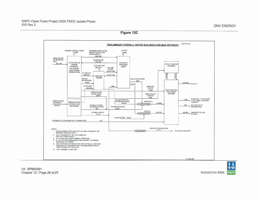
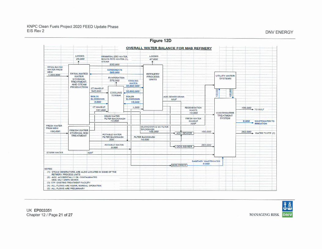
Figures 12C and 12 D provide Water Balance diagrams for the MAA and MAB refineries, respectively. Some of the water conservation methods previously described are illustrated in blue on these diagrams.
UK EP003351 11 Chapter 12 I Page 19 of 27 MANAGING RISK ~
KNPC Clean Fuels Project 2020 FEED Update Phase EIS Rev 2
Figure 12C
PRELIMINARY OVERALL WATER BALANCE FOR MAA REFINERY
HEADER LOSSES & VENTS 11.086
OEMJNERALIZEO WATER. BOILER FEED WATER,
LOSSES
3.806
N
UK EP003351
600,128 DESALINATED WATER FROM CONDENSATE MEW 374,275
42 1123 DESAUNATED WATER
EVAPORATI ON STORAGE, TREATMENT, 282.r3 AND STEAM
PRODUCTION CTMAKEUP
164,878 COOLING
BOILER TOWER
BLOWDOWN
3,940
CT MAKEUP
164 878
I
FRESH WATER w FRESH WATER FROM MEW
STORAGE AND 16Q,2Q4 TREATMENT
POTENTIALLY CONTAMINATED STORMWATER
REFINERY PROCESS UNITS
2. AOC: ACCIDENTALLY OIL CONTAMINATED ODS: OILY DRIPS SEWER
3. ALL FLOWS ARE KG/HR. NORMAL OPERATION
DEMINWATER FILTER WASH
6,528
POTABLE WATER FILTER BACKWASH
100
POTABLE W ATER 4.716
NNF
4 All FLOWS ARE PRELIMINARY AND SUBJECT TO CHANGE DURING DETAIL DESIGN
5. AOC SYSTEM INLET AND OUT\. ET ARE NOT EQUAL, BECAUSE WASTEWATER TREATMENT UNIT W AS DESIGNED EARLIER THEN THE REST OF THE UNITS.
6. NNF = NORMALLY NO FLOW
Chapter 12 I Page 20 of 27
REFINERY UTILITY WATER PROCESS
SYSTEMS UNITS COOLING WATER
10.207.200 ,---.
~r ~1 10.207.200
AOC SEWER DRAIN NNF
I 222,047
~ 'l REGENER WASTE
I I 7 ,938 WASTEWATER
I I I I TREATMENT
FRESH WATER SYSTEM MAKE UP
NNF I BLOWOOWN & ss I ! (NOTES 2,5) Fll TEA BACKWASH
50.923 40,300
I AOC SYSTEM
i FILTER BACKWASH 6,628
I (NOTE 2) 204.447
ODS SYSTEM
SOUR WATER 15.600 J
SANITARY WASTEWATER
6UILOINGS 3.716
(NOTES 3.4)
205.000
1.065
225
26.800
TO GULF
BIOSOUDS TO DISPOSAL AT NATIONAL CLEANING COMPANY
OILY SOliDS TO INCINERATION
CENTRA TE TO ODS SYSTEM
TY
01·Doc·09
DNV ENERGY
11 MANAGING RISK r·h!rifJ
KNPC Clean Fuels Project 2020 FEED Update Phase EIS Rev 2
Figure 120
OVERALL WATER BALANC E FOR MAB REFINERY
DESALitiA TED WATER FROM MEW 1.024.000
OEMINERALIZEO WATER, BOILER FEED WATER (1), STEAM
932.000
CDNOENSATI.
DESALINATED I• 505,000 I WATER
STORAGE TREATMENT AND S TEAM,
PRODUC TIO N CTMAKEUP ~2.000
BOILER BLOWOOWN
3,000
EVAPORATKlN 1578,000 COOLING
. WATI.R
32,692.000
COOLING I• 32.692,000 TOWE R I
BOLER BLOWOOWN
18,000
LOSSES
47,000
REFINERY PROCESS
UNIT S
ADC SEWER DRAIN NNF
UTILITY WATER SYST EMS
CT MAKEUP I I 1,000 . I I I I REGENERATION
1 1 r 13,ooo I w As TEWATER I 181,000 · 1 I ~ WASTE I OEMIN W ATER ' TREATMENT
I FILTER BACKWASH I I - L- I I FRESH W ATI.R I SYSTEM 14,000 MAKEUP
NNF FRESH WATER
FROM MEW I FRESH WATER 190,000 ST ORAGEANO
TREATMENT
+
STORM WATER
NOTES:
POTABLE WATER FILTER BA CKWASH
200
POTABLE WA TER 9 ,000
(1) STEAM GENERATORS ARE ALSO LOCATED IN SOME Of THE REFINERY PROCESS UNITS
(2) AOC: ACCIDENTALLY OIL CONTAMitiATED DOS: OILY DRIPS SEW ER _
(3) ETF: EX ISTING TREATMENT FACILITY (4) ALL FLOWS ARE KGJHR. NORMAL OPERATION (S) ALL FLOWS ARE PRELWAINARY
UK EP003351 Chapter 12 I Page 21 of 27
BLOWOOWN & SS FLTI.R BACKWASH
166,000
f iLTER BACKWASH 14,000
180,000
363,000
SANITARY WASTEWATER 8,000
DNV ENERGY
I 8,000 • ::~TERTO
362,000 WATER TO ETF (3)
!I MANAGING RISK r·j¥f!rJ
KNPC Clean Fuels Project FEED Update Phase EIS Rev 2
12.5 Discharge Criteria
DNV ENERGY
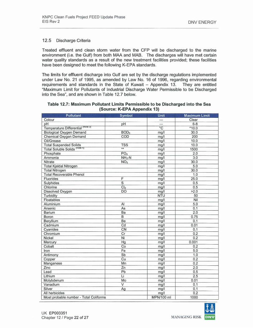
Treated effluent and clean storm water from the CFP will be discharged to the marine environment (i.e. the Gulf) from both MAA and MAB. The discharges will have met certain water quality standards as a result of the new treatment facilities provided; these facilities have been designed to meet the following K-EPA standards.
The limits for effluent discharge into Gulf are set by the discharge regulations implemented under Law No. 21 of 1995, as amended by Law No. 16 of 1996, regarding environmental requirements and standards in the State of Kuwait - Appendix 13. They are entitled "Maximum Limit for Pollutants of Industrial Discharge Water Permissible to be Discharged into the Sea", and are shown in Table 12.7 below.
Table 12.7: Maximum Pollutant Limits Permissible to be Discharged into the Sea (Source: K-EPA Appendix 13)
Pollutant Symbol Unit Maximum Limit Colour --- Clear pH pH --- 6-8 Temperature Differential 1" o e ~~ ·c *10.0 Biological Oxygen Demand SODs mg/1 30.0 Chemical Oxygen Demand COD mg/1 200 Oil/Grease mq/1 10.0 Total Suspended Solids TSS mg/1 10.0 Total Soluble Solids [NO e ql ** mg/1 1500 Phosphate P04 mg/1 2.0 Ammonia NH3-N mg/1 3.0 Nitrate N03 mq/1 30.0 Total Kjeldal Nitrogen mg/1 5.0 Total Nitrogen mg/1 30.0 Total Recoverable Phenol mg/1 1.0 Fluorides F mg/1 25.0 Sulphides s mg/1 0.5 Chlorine Cl2 mg/1 0.5 Dissolved Oxygen DO mg/1 >2.0 Turbidity NTU 50 Floatables mg/1 Nil Aluminium AI mq/1 5.0 Arsenic As mg/1 0.1 Barium Ba mg/1 2.0 Boron B mg/1 0.75 Beryllium Be mg/1 0.1 Cadmium Cd mg/1 0.01 Cyanides CN mg/1 0.1 Chromium Cr mg/1 0.2 Nickel Ni mg/1 0.2 Mercury Hg mg/1 0.001 Cobalt Co mg/1 0.2 Iron Fe mg/1 5.0 Antimony Sb mg/1 1.0 Copper Cu mg/1 0.2 Manganese Mn mg/1 0.2 Zinc Zn mg/1 2.0 Lead Pb mg/1 0.5 Lithium Li mg/1 2.5 Molybdenum Mo mg/1 0.01 Vanadium V mg/1 0.1 Silver Ag mg/1 0.1 A ll herbicides mg/1 0.2 Most probable number- Total Coliforms MPN/100 ml 1000
UK EP003351 Chapter 12 I Page 22 of 27
[I MANAGING RISK £m2
KNPC Clean Fuels Project FEED Update Phase EIS Rev 2
Notes:
DNV ENERGY
(1) Effluent criteria are applicable to the combined effluent from all systems. Individual systems may vary slightly provided the composite is compliant with the above criteria.
(2) Effluent metal content is not guaranteed as CFP WWT facilities do not treat for metals. Based on historical refinery operations, metals are not expected to be in excess of K-EPA limits and, therefore, no metal removal processes have been included in the WWT design. (3) Temperature differential refers to the difference between discharged effluent temperature and Gulf water temperature at the point of entry.
(4) Should be considered same as Total Dissolved Solids (TDS).
12.6 Wastewater Monitoring
Monitoring of wastewater generated by new. and modified CFP facilities will be incorporated as part of the Environmental Management System (EMS) for the existing KNPC refineries.
Effluent monitoring at the point of discharge from the Observation Basin at the MAA Refinery and from the existing Mixing Basin at the MAB Refinery will be provided. Continuous on-line analyzers will be provided for pH, Total Oil & Grease, and turbidity. Inline sampling for Dissolved Oxygen and temperature will also be provided in the proximity of the effluent pump discharge. Contaminated water will be directed to the ODS System.
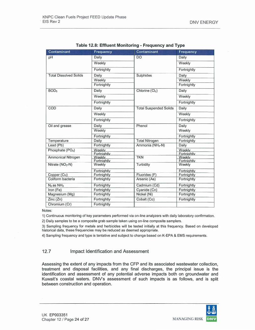
Table 12.8 below provides a description of the wastewater parameters and frequency of effluent monitoring that will be applicable to discharges from the CFP facilities based on KNPC's 'Procedure on Monitoring of Wastewater Treatment and Disposal'. All testing will be performed as per K-EPA approved methods. The flow rate and quality of wastewater will be monitored to ensure optimal treatment and compliance with the applicable K-EPA requirements.
In the event that sample test results indicate a deviation or trend of deviation from the specified quality, the operating parameters will be adjusted, maintained and monitored. The effectiveness of the implemented adjustment will be confirmed by test analysis of check samples.
Storm water that falls within the CFP paved (i.e. process) areas will be collected by the AOC system and routed to the WWT Units at MAA or MAB where it will ultimately be monitored at the point of discharge from the Observation Basin (at MAA) or the point of discharge from the existing Mixing Basin (at MAB). Storm water runoff from outside the paved areas (i.e. OSBL) of both MAA and MAB is expected to be clean. However, as an added precaution and environmental best practice measure, this water will be collected and routed to an Oil Catcher. The Oil Catcher is a large concrete sump with a floating oil skimmer and sand traps to remove solids and sand. Skimmed oil will be removed by vacuum truck and taken to the CPI in the WWT Unit. The clean storm water discharge from the Oil Catcher will be pumped to a release point at the shoreline. Continuous monitoring is not provided since the storm water from OSBL areas is normally clean. However, grab samples may be collected and analyzed as required to verify compliance with K-EPA effluent standards prior to storm water discharge.
UK EP003351 Chapter 12 I Page 23 of 27
11 MANAGING RISK ~
KNPC Clean Fuels Project FEED Update Phase E IS Rev 2 DNV ENERGY
Table 12.8: Effluent Monitoring- Frequency and Type Contaminant Frequency Contaminant Frequency
pH Daily DO Daily
Weekly Weekly
Fortnightly Fortnightly
Total Dissolved Solids Daily Sulphides Daily Weekly Weekly Fortnightly Fortnightly
BOOs Daily Chlorine {CI2) Daily
Weekly Weekly
Fortnightly Fortnightly
COD Daily Total Suspended Solids Daily
Weekly Weekly
Fortnightly Fortnightly
Oil and grease Daily Phenol Daily Weekly Weekly
Fortnightly Fortnightly Temperature Daily Total Nitrogen Fortnightly Lead (Pb) Fortnightly Ammonia (NH3-N) Daily
Phosphate (P04) Weeklv Weeklv Fortniahtlv ,...,
Ammonical Nitrogen WP.P.klv TKN WP.P.klv Fortniahtlv Fortniahtlv
Nitrate (N03-N) Weekly Turbidity Weekly
Fortniahtlv Fortniahtlv Copper (Cu) Fortnightly Fluorides (F) Fortnightly Coliform bacteria Fortnightly Arsenic (As) Fortnightly
N2as NH3 Fortnightly Cadmium (Cd) Fortnightly Iron (Fe) Fortnightly Cyanide (Cn) Fortnightly Magnesium (Mg) Fortnightly Nickel (Ni) Fortnightly
Zinc (Zn) Fortnightly Cobalt (Co) Fortnightly
Chromium (Cr) Fortnightly
Notes:
1) Continuous monitoring of key parameters performed via on-line analyzers with daily laboratory confirmation.
2) Daily samples to be a composite grab sample taken using on-line composite samplers.
3) Sampling frequency for metals and herbicides will be tested initially at this frequency. Based on developed historical data, these frequencies may be reduced as deemed appropriate.
4) Sampling frequency and type is tentative and subject to change based on K-EPA & EMS requirements.
12.7 Impact Identification and Assessment
Assessing the extent of any impacts from the CFP and its associated wastewater collection, treatment and disposal facilities, and any final discharges, the principal issue is the identification and assessment of any potential adverse impacts both on groundwater and Kuwait's coastal waters. DNV's assessment of such impacts is as follows, and is split between construction and operation.
UK EP003351 Chapter 12 I Page 24 of 27
(I MANAGING RISK ~
KNPC Clean Fuels Project FEED Update Phase EIS Rev 2
CFP Construction Phase:
Category: ENVIRONMENT
DNV ENERGY
Consequence evaluation for: Wastewater Management during Construction of the CFP
1. General description (situation and characteristics):
Evaluation of the value I sensitivity: Note: This section describes the sensitivity of the area in question. Following a review of existing information regarding the site's sensitivity, a sensitivity rating or value is given.
The only discharge of treated wastewater or storm water from the CFP during construction will be after sampling and analysis to verify compliance with the applicable K-EPA discharge criteria. Apart from these discharges, the sensitivity of the area is also relevant if the allocated measures in place to properly manage wastewater and its treatment, reuse and discharge fail, and a contaminating release to ground/groundwater/coastal water occurs.
Although there are no significant groundwater resources in the refinery area, the coastal environment is subject to some stress owing to the industrial nature of the study area . As such, the value/sensitivity is deemed Medium.
Low Medium High 1-----------X ------------1
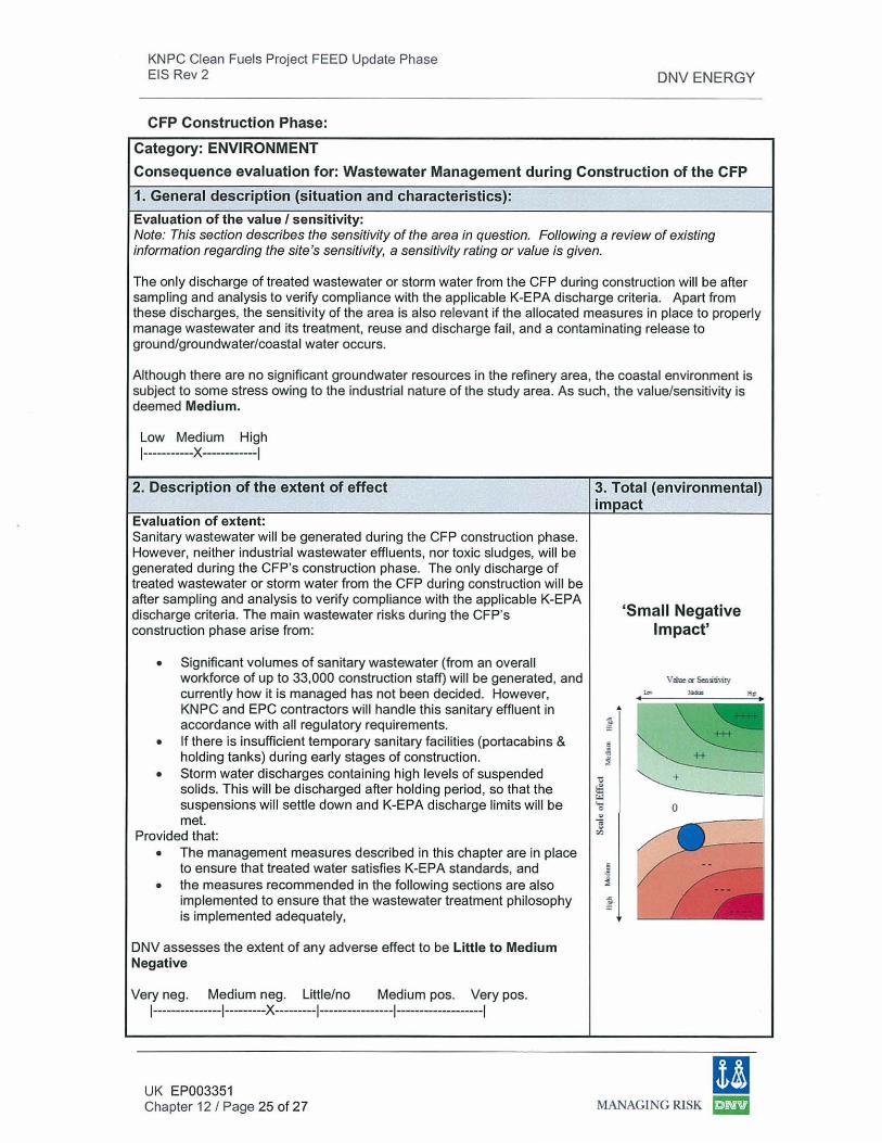
2. Description of the extent of effect
Evaluation of extent: Sanitary wastewater will be generated during the CFP construction phase. However, neither industrial wastewater effluents, nor toxic sludges, will be generated during the CFP's construction phase. The only discharge of treated wastewater or storm water from the CFP during construction will be after sampling and analysis to verify compliance with the applicable K-EPA discharge criteria. The main wastewater risks during the CFP's construction phase arise from:
• Significant volumes of sanitary wastewater (from an overall workforce of up to 33,000 construction staff) will be generated, and currently how it is managed has not been decided. However, KNPC and EPC contractors will handle this sanitary effluent in accordance with all regulatory requirements.
• If there is insufficient temporary sanitary facilities (portacabins & holding tanks) during early stages of construction.
• Storm water discharges containing high levels of suspended solids. This will be discharged after holding period, so that the suspensions wi ll settle down and K-EPA discharge limits wi ll be met.
Provided that: • The management measures described in this chapter are in place
to ensure that treated water satisfies K-EPA standards, and • the measures recommended in the following sections are also
implemented to ensure that the wastewater treatment phi losophy is implemented adequately,
DNV assesses the extent of any adverse effect to be Little to Medium Negative
Very neg. Medium neg. Little/no Medium pas. Very pos. 1---------------1---------X ---------l----------------1-------------------l
UK EP003351 Chapter 12 I Page 25 of 27
3. Total (environmental) im act
~
~
E
-3 ~
'tS
ffi '-
0
" 1i tl}
5
~ ~
~
..
'Small Negative Impact'
+
0
11 MANAGING RlSK ~
KNPC Clean Fuels Project FEED Update Phase EIS Rev 2
CFP Operational Phase:
Category: ENVIRONMENT
DNV ENERGY
Consequence evaluation for: Wastewater Management during Operation of the CFP
1. General description (situation and characteristics):
Evaluation of the value I sensitivity: Note: This section describes the sensitivity of the area in question. Following a review of existing information regarding the site's sensitivity, a sensitivity rating or value is given.
Wastewater and storm water from the CFP will discharge to Gulf waters (wastewater will discharge via 500m long-Gulf oufalls), after meeting opportunities for water reuse on site (e.g. for irrigation) and after satisfying K-EPA discharge criteria. Apart from the discharges, the sensitivity of the area is also relevant if the allocated measures in place to properly manage wastewater and its treatment, reuse and discharge fail, and a contaminating release to ground I groundwater I coastal water occurs.
Although there are no significant groundwater resources in the refinery area, the coastal environment is subject to some stress owing to the industrial nature of the study area . As such, the value/sensitivity is deemed Medium.
Low Medium High 1-----------X -------------1
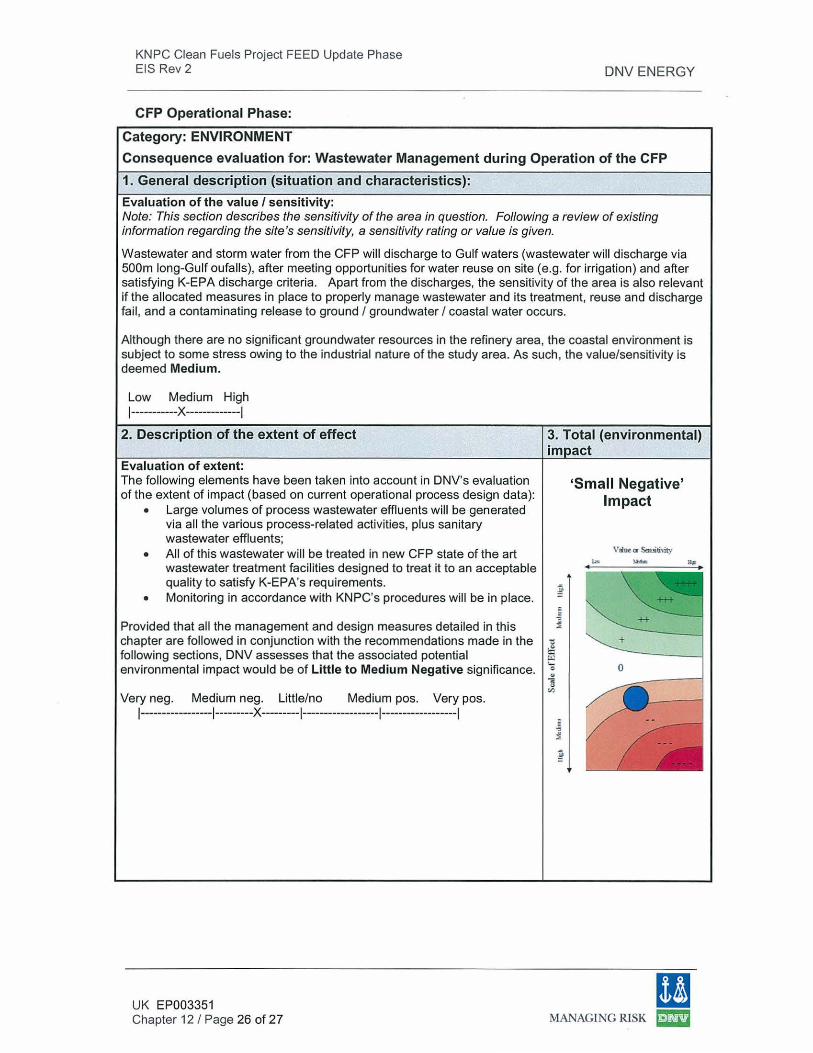
2. Description of the extent of effect
Evaluation of extent: The following elements have been taken into account in DNV's evaluation of the extent of impact (based on current operational process design data):
• Large volumes of process wastewater effluents will be generated via all the various process-related activities, plus sanitary wastewater effluents;
• All of this wastewater will be treated in new CFP state of the art wastewater treatment facilities designed to treat it to an acceptable quality to satisfy K-EPA's requirements.
• Monitoring in accordance with KNPC's procedures will be in place.
Provided that all the management and design measures detailed in this chapter are followed in conjunction with the recommendations made in the following sections, DNV assesses that the associated potential environmental impact would be of little to Medium Negative significance.
Very neg. Medium neg. Little/no Medium pos. Very pos. 1-----------------1---------X ---------1------------------l------------------l
UK EP003351 Chapter 12 I Page 26 of 27
3. Total (environmental) im act
u
; ~
<S
t: ~ '-
Q .. a "'
~ ~
~
'Small Negative' Impact
+
0
11 MANAGING RISK ~
KNPC Clean Fuels Project FEED Update Phase EIS Rev 2
12.8 Conclusions
DNV ENERGY
DNV has assessed the environmental impacts from the collection, treatment and reuse of process and sanitary wastewater effluents generated during both the CFP's construction and operational phases as 'Little to Medium Negative Impact'.
Overall, it is concluded that the planned new CFP wastewater collection and treatment facilities are state of the art, and constitute 'best practice' and apply a considerable number of BACT elements. The CFP wastewater facilities will be designed, built and operated in such a way as to meet best practice and K-EPA's environmental criteria.
12.9 Recommendations
In order to augment the robust approach to addressing and mitigating environmental impacts during the CFP's construction and subsequent operations, this study makes the following additional recommendations:
• lt will be important to ensure during operation of the CFP's wastewater treatment facilities (for both the construction and operation phases), that the wastewater discharge monitoring results are audited by KNPC HSE on a regular basis as part of EMS, and audited at annual intervals by an independent party.
• lt will be important to ensure that the sanitary wastewater and storm water collection/treatment facilities are made available at the earliest stage possible during construction, as it is currently unclear how these will be managed. lt is recommended that each EPC contractor make this an early priority for the CFP construction, such that compliance with all regulatory requirements is met.
UK EP003351 Chapter 12 I Page 27 of 27
(I MANAGING RlSK ~
KNPC Clean Fuels Project 2020 Feed Update Phase EIS Rev 2 DNV ENERGY
13.0 Preliminary Traffic Impact Assessment
13.1 Introduction
A preliminary Traffic Impact Assessment (TIA) was conducted during the FEED Phase of the CFP 2020 to ensure that increased traffic resulting from the construction and operation of the CFP would not significantly impact the surrounding area. lt focused on the CFP site and surrounding approach roads. The data and information in this Chapter is from the FEED Phase and has not been updated to reflect any FEED Update changes, because a Comprehensive Traffic Impact Assessment will be conducted in the future.
This preliminary TIA took the following items into account: • Approach to the CFP site • Baseline traffic flows • Distribution of traffic • Traffic generated by construction • Predicted CFP construction impacts • Traffic generated by KNPC refinery operations • Predicted operational impacts
13.2 Methodology
This preliminary TIA incorporates the following elements:
• Desktop review to gain an understanding of road network setting & road classification
• Visit to site to identify main routes and collection of baseline traffic data • Assessment of traffic impacts • Recommend mitigation measures
13.3 Site Location and Road Network Setting
13.3.1 Road Classification
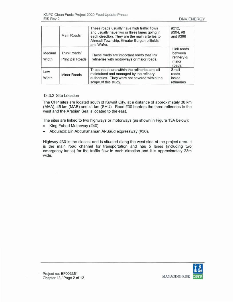
Roads are classified into three main categories as shown in Table 13.1. Description of the road conditions and traffic loadings are discussed in Section 13.5.
Class Type
High Motorways/
Width Highway
Project no: EP003351 Chapter 13 I Page 1 of 12
Table 13.1 Road Categories
Description Roads
There are three or more lanes in each #30 and direction and generally have a maximum #40 speed limit of 120 ki lometres per hour. They are cross country roads linking important places both within and outside the country such as Kuwait City, Saudi Arabia, etc.
(I MANAGING RlSK ~
KNPC Clean Fuels Project 2020 Feed Update Phase EIS Rev 2 DNV ENERGY
These roads usually have high traffic flows #212,
Main Roads and usually have two or three lanes going in #304,#8 each direction. They are the main arteries to and #306 Ahmadi Township , Greater Burgan oilfields and Wafra.
Link roads Medium Trunk roads/ These roads are important roads that link between
refinery & Width Principal Roads refineries with motorways or major roads.
major roads.
Low These roads are within the refineries and all Small
Minor Roads maintained and managed by the refinery roads Width authorities. They were not covered within the inside
scope of this study. refineries
13.3.2 Site Location
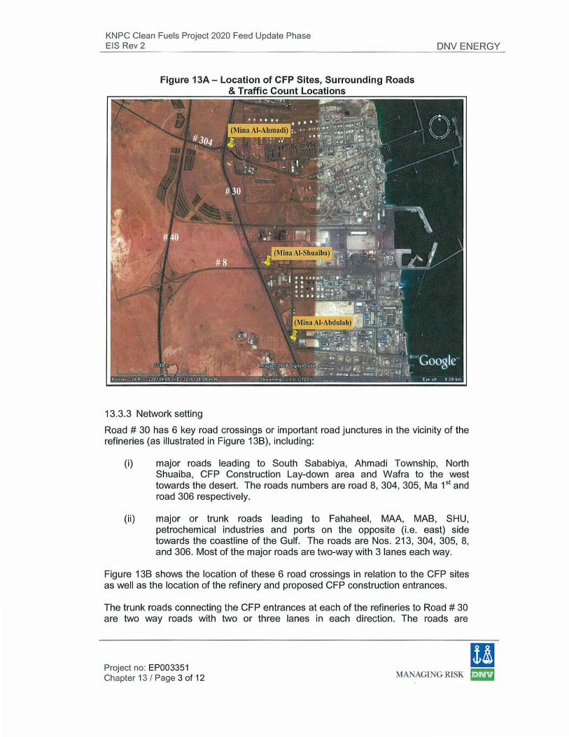
The CFP sites are located south of Kuwait City, at a distance of approximately 38 km (MAA), 45 km (MAB) and 41 km (SHU). Road #30 borders the three refineries to the west and the Arabian Sea is located to the east.
The sites are linked to two highways or motorways (as shown in Figure 13A below): • King Fahad Motorway (#40) • Abdulaziz Bin Abdulrahaman AI-Saud expressway (#30).
Highway #30 is the closest and is situated along the west side of the project area. lt is the main road channel for transportation and has 5 lanes (including two emergency lanes) for the traffic flow in each direction and it is approximately 23m wide.
m Project no: EP003351 Chapter 13 I Page 2 of 12 MANAGING RISK ID
KNPC Clean Fuels Project 2020 Feed Update Phase EIS Rev 2 DNV ENERGY
13.3.3 Network setting
Road# 30 has 6 key road crossings or important road junctures in the vicinity of the refineries (as illustrated in Figure 13B), including:
(i) major roads leading to South Sababiya, Ahmadi Township, North Shuaiba, CFP Construction Lay-down area and Wafra to the west towards the desert. The roads numbers are road 8, 304, 305, Ma 151 and road 306 respectively.
(ii) major or trunk roads leading to Fahaheel, MAA, MAB, SHU, petrochemical industries and ports on the opposite (i.e. east) side towards the coastline of the Gulf. The roads are Nos. 213, 304, 305, 8, and 306. Most of the major roads are two-way with 3 lanes each way.
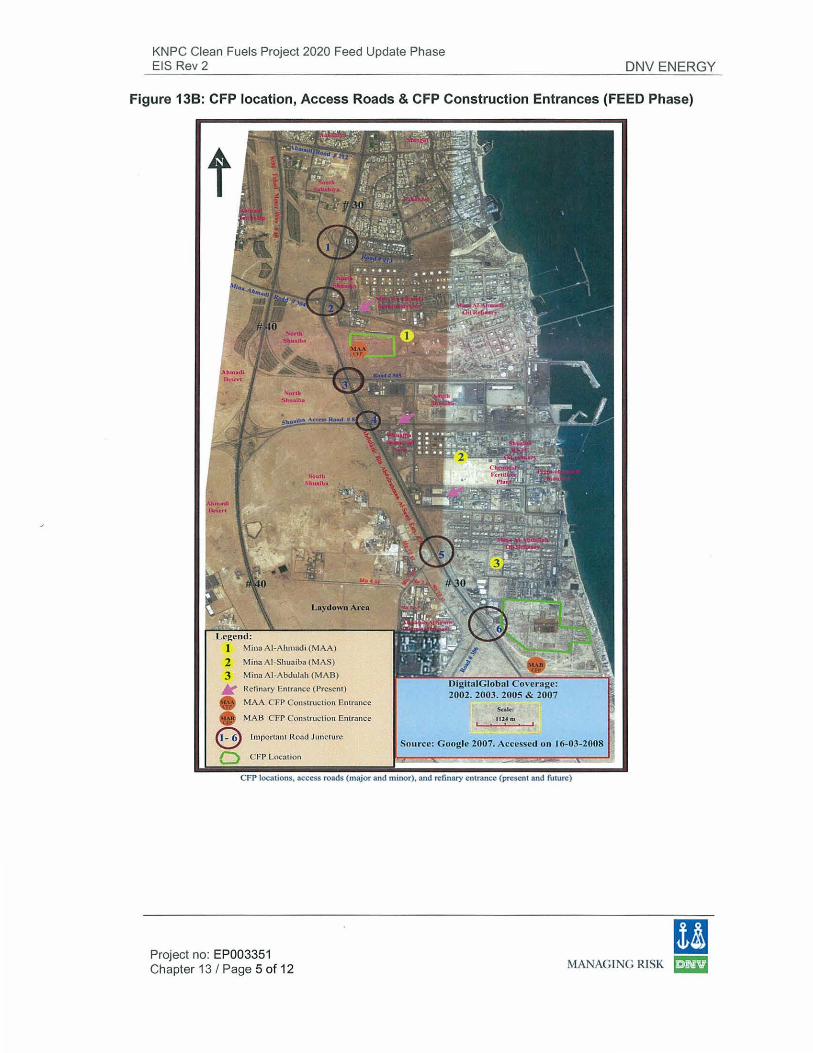
Figure 13B shows the location of these 6 road crossings in relation to the CFP sites as well as the location of the refinery and proposed CFP construction entrances.
The trunk roads connecting the CFP entrances at each of the refineries to Road # 30 are two way roads with two or three lanes in each direction. The roads are
11 Project no: EP003351 Chapter 13 I Page 3 of 12 MANAGlNG RISK E:lm
KNPC Clean Fuels Project 2020 Feed Update Phase EIS Rev 2 DNV ENERGY
approximately 1 Om wide. The approximate distances between Road #30 and the existing entrance to each refinery are as fo llows:
• MAA: 1.31 km • SHU: 1.26 km • MAB: 1.44 km* *Measurements from Google earth
The average speed of traffic is 30 km/hr on the roads leading to the gate of the refineries. The speed of traffic on the expressways is significantly higher.
13.4 Number of Employees - Existing and Future
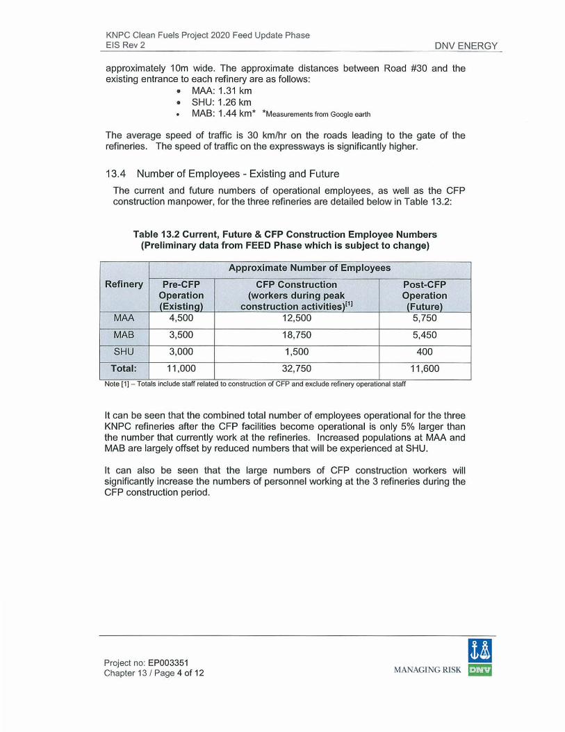
The current and future numbers of operational employees, as well as the CFP construction manpower, for the three refineries are detailed below in Table 13.2:
Table 13.2 Current, Future & CFP Construction Employee Numbers (Preliminary data from FEED Phase which is subject to change)
Approximate Number of Employees
Refinery Pre-CFP CFP Construction Post-CFP Operation (workers during peak Operation (Existing) construction activities )[11 (Future)
MAA 4,500 12,500 5,750
MAB 3,500 18,750 5,450
SHU 3,000 1,500 400
Total: 11 ,000 32,750 11 ,600
Note [1] - Totals mclude staff related to construction of CFP and exclude refinery operational staff
lt can be seen that the combined total number of employees operational for the three KNPC refineries after the CFP facilities become operational is on ly 5% larger than the number that currently work at the refineries. Increased populations at MAA and MAB are largely offset by reduced numbers that wi ll be experienced at SHU.
lt can also be seen that the large numbers of CFP construction workers will significantly increase the numbers of personnel working at the 3 refineries during the CFP construction period.
(I Project no: EP003351 Chapter 13 I Page 4 of 12 MANAGING RISK ~
KNPC Clean Fuels Project 2020 Feed Update Phase EIS Rev 2 DNV ENERGY
Figure 138: CFP location, Access Roads & CFP Construction Entrances (FEED Phase)
Laydown Area
I 2 Mina AI-Shuoibn (1\IAS}
3 M inn AI-Abdulah (MA B)
K Rcfinary Entroncc (Present)
• MAA CFP Constnoction Entrnnce
• M A B CFP Construction Entrance e Important Road Juncture
Q CFP Location
2002. 2003. 2005 & 2007
Sa~:
1114 m
Source: G uoglc 2007. Accessed on 16-03-2008
CFP locations, access roads (major and minor), and refin:uy entrance (present and future)
Project no: EP003351 Chapter 13 I Page 5 of 12
(I MANAGING RISK ~
KNPC Clean Fuels Project 2020 Feed Update Phase EIS Rev 2 DNV ENERGY
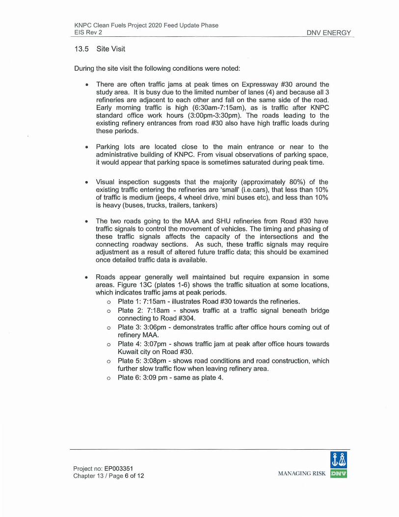
13.5 Site Visit
During the site visit the following conditions were noted:
• There are often traffic jams at peak times on Expressway #30 around the study area. lt is busy due to the limited number of lanes (4) and because all 3 refineries are adjacent to each other and fall on the same side of the road. Early morning traffic is high (6:30am-7:15am), as is traffic after KNPC standard office work hours (3:00pm-3:30pm). The roads leading to the existing refinery entrances from road #30 also have high traffic loads during these periods.
• Parking lots are located close to the main entrance or near to the administrative building of KNPC. From visual observations of parking space, it would appear that parking space is sometimes saturated during peak time.
• Visual inspection suggests that the majority (approximately 80%) of the existing traffic entering the refineries are 'small' (i.e.cars ), that less than 1 0% of traffic is medium Ueeps, 4 wheel drive, mini buses etc), and less than 10% is heavy (buses, trucks, trailers , tankers)
• The two roads going to the MAA and SHU refineries from Road #30 have traffic signals to control the movement of vehicles. The timing and phasing of these traffic signals affects the capacity of the intersections and the connecting roadway sections. As such, these traffic signals may require adjustment as a result of altered future traffic data; this should be examined once detailed traffic data is available.
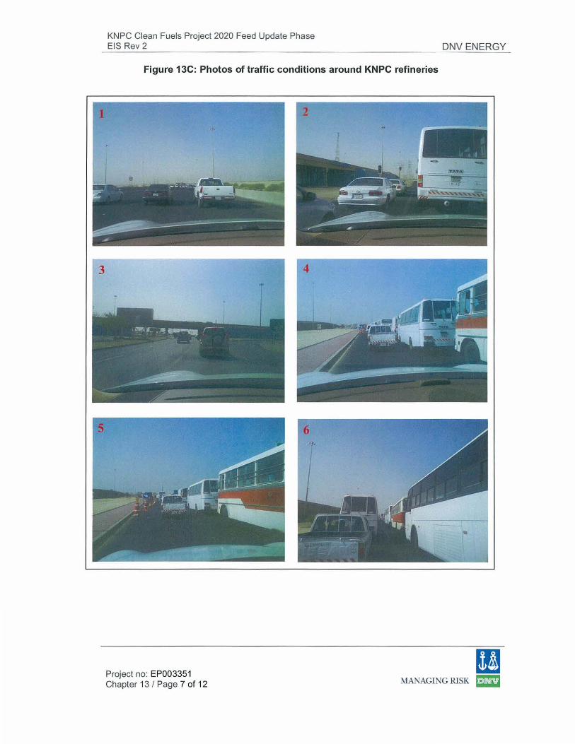
• Roads appear generally well maintained but require expansion in some areas. Figure 13C (plates 1-6) shows the traffic situation at some locations, which indicates traffic jams at peak periods.
o Plate 1: 7:15am - illustrates Road #30 towards the refineries. o Plate 2: 7:18am - shows traffic at a traffic signal beneath bridge
connecting to Road #304. o Plate 3: 3:06pm - demonstrates traffic after office hours coming out of
refinery MAA. o Plate 4: 3:07pm - shows traffic jam at peak after office hours towards
Kuwait city on Road #30. o Plate 5: 3:08pm - shows road conditions and road construction, which
further slow traffic flow when leaving refinery area. o Plate 6: 3:09 pm - same as plate 4.
(I Project no: EP003351 Chapter 13 I Page 6 of 12 MANAGING RISK ~
KNPC Clean Fuels Project 2020 Feed Update Phase EIS Rev 2 DNV ENERGY
Figure 13C: Photos of traffic conditions around KNPC refineries
Project no: EP003351 Chapter 13 I Page 7 of 12
(I MANAGING RISK ~
KNPC Clean Fuels Project 2020 Feed Update Phase EIS Rev 2 DNV ENERGY
13.6 Traffic Data
WES conducted a simple traffic survey to understand the traffic volumes and types of vehicles near the refineries entrances between 6.45am and 3.15pm. The office workers at the three refineries start from ?am, with most of the employees inside the refinery by this time. There is significantly less traffic movement after ?am and before 3pm, when office workers finish for the day.
The traffic survey was divided into three time slots: 1. 6:45am-9:00am, 2. 10:00 am-12:00 noon 3. 1 :00pm-3.15pm.
The surveys were carried out on Sunday March 30 2008 (MAA), Monday March 31 2008 (SHU) and Tuesday April 1 2008 (MAB). lt should be noted that these figures are indicative only, as they were only collected over one day at each refinery, and are not intended to be comprehensive.
The three locations for the traffic sampling for the three refineries are shown in Figure 13A. All cars that entered the local roads leading to the refinery gates were included within the survey. lt should be noted that for Shuaiba this will overestimate traffic, because the road also leads to other Shuaiba industrial organizations.
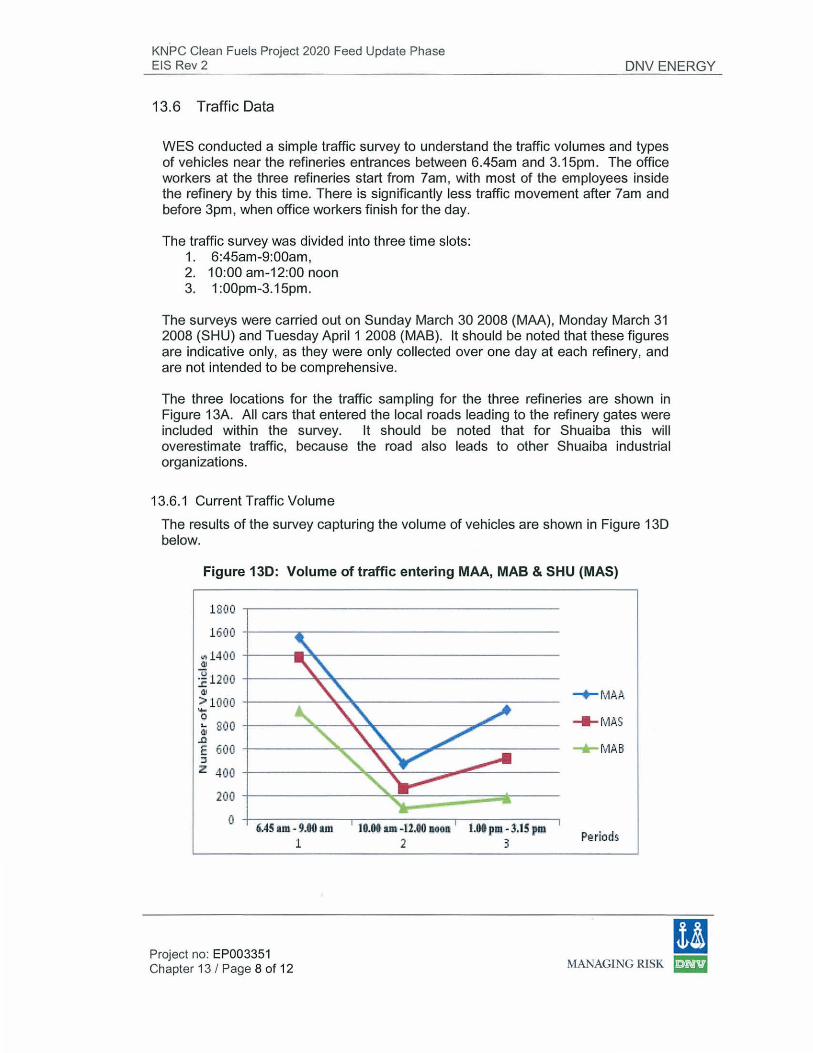
13.6.1 Current Traffic Volume
The results of the survey capturing the volume of vehicles are shown in Figure 130 below.
Figure 130: Volume of traffic entering MAA, MAB & SHU (MAS)
1800 ~-----------------------------------
1600 +-----~---------------------------
~ 1400 +-----.r~--------------------------<11
~1200 +-------~~------------------------.!: ell
> 1000 +-----~--~~----------------~-----'+-0 d. 800 +-----~~--~~----------~~------
..0 E 600 +---------~~~~--~~------------:J
z 400 +-----------~~~~--~--~---------
200 t-----------~~~~~--~r----
0 +-----------~----------~----------~ 5AS am- U O.m l.Of pm - :J.IS pm
1 3
-+-MAA
_.,_ fVIAB
(I Project no: EP003351 Chapter 13 I Page 8 of 12 MANAGING RISK ~
KNPC Clean Fuels Project 2020 Feed Update Phase EIS Rev 2 DNV ENERGY
Peak traffic is just before the start of office hours (7:00am) and just after the end of office hours (3:00pm). Traffic is lower during the middle of the working day. Information provided by KNPC suggests that the more than two thirds of traffic takes place during office hours. As might be expected, there is significantly less refinery traffic during weekends.
Note that the traffic survey conducted at Mina AI-Shuaiba was conducted on the road leading not only to Shuiaba refinery, but also to other Shuiaba industrial organizations (e.g. PlC, EQUATE, Gulf Bank). Hence traffic count for Shuaiba is overestimated.
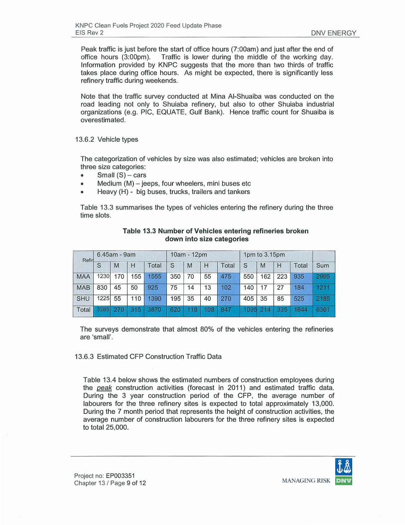
13.6.2 Vehicle types
The categorization of vehicles by size was also estimated; vehicles are broken into three size categories: • Small (S) -cars • Medium (M)- jeeps, four wheelers, mini buses etc • Heavy (H) - big buses, trucks, trailers and tankers
Table 13.3 summarises the types of vehicles entering the refinery during the three time slots.
Table 13.3 Number of Vehicles entering refineries broken down into size categories
10am- 12pm 1pm to 3.15pm
Total S M H Total S M H Total
350 70 55 550 162
140 17 27
The surveys demonstrate that almost 80% of the vehicles entering the refineries are 'small '.
13.6.3 Estimated CFP Construction Traffic Data
Table 13.4 below shows the estimated numbers of construction employees during the peak construction activities (forecast in 2011) and estimated traffic data. During the 3 year construction period of the CFP, the average number of labourers for the three refinery sites is expected to total approximately 13,000. During the 7 month period that represents the height of construction activities, the average number of construction labourers for the three refinery sites is expected to total 25,000.
11 Project no: EP003351 Chapter 13 I Page 9 of 12 MANAGING RlSK ~
KNPC Clean Fuels Project 2020 Feed Update Phase EIS Rev 2 DNV ENERGY
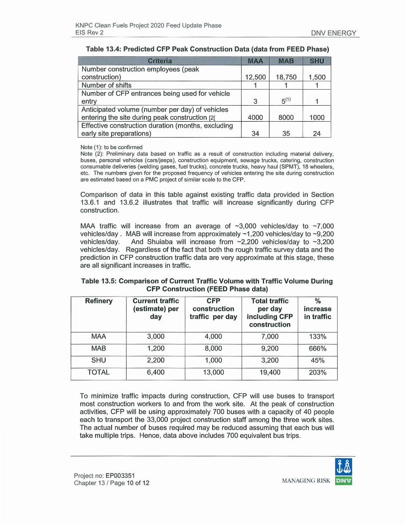
Table 13.4: Predicted CFP Peak Construction Data (data from FEED Phase)
Criteria MAA MAB SHU Number construction employees (peak construction) 12,500 18,750 1,500 Number of shifts 1 1 1 Number of CFP entrances being used for vehicle entry 3 5(1) 1 Anticipated volume (number per day) of vehicles entering the site during peak construction [2[ 4000 8000 1000 Effective construction duration (months, excluding early site preparations) 34 35 24
Note (1): to be confirmed Note (2): Preliminary data based on traffic as a result of construction including material delivery, buses, personal vehicles (cars/jeeps), construction equipment, sewage trucks, catering, construction consumable deliveries (welding gases, fuel trucks), concrete trucks, heavy haul (SPMT), 18 wheelers, etc. The numbers given for the proposed frequency of vehicles entering the site during construction are estimated based on a PMC project of similar scale to the CFP.
Comparison of data in this table against existing traffic data provided in Section 13.6.1 and 13.6.2 illustrates that traffic will increase significantly during CFP construction.
MAA traffic will increase from an average of -3,000 vehicles/day to -7,000 vehicles/day . MAB will increase from approximately -1 ,200 vehicles/day to -9,200 vehicles/day. And Shuiaba will increase from -2,200 vehicles/day to -3,200 vehicles/day. Regardless of the fact that both the rough traffic survey data and the prediction in CFP construction traffic data are very approximate at this stage, these are all significant increases in traffic.
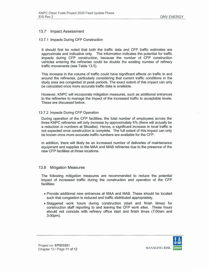
Table 13.5: Comparison of Current Traffic Volume with Traffic Volume During CFP Construction (FEED Phase data)
Refinery Current traffic CFP Total traffic % (estimate) per construction per day increase
day traffic per day including CFP in traffic construction
MAA 3,000 4,000 7,000 133%
MAB 1,200 8,000 9,200 666%
SHU 2,200 1,000 3,200 45%
TOTAL 6,400 13,000 19,400 203%
To minimize traffic impacts during construction, CFP will use buses to transport most construction workers to and from the work site. At the peak of construction activities, CFP will be using approximately 700 buses with a capacity of 40 people each to transport the 33,000 project construction staff among the three work sites. The actual number of buses required may be reduced assuming that each bus will take multiple trips. Hence, data above includes 700 equivalent bus trips.
(I Project no: EP003351 Chapter 13 I Page 10 of 12 MANAGING RJSK [D
KNPC Clean Fuels Project 2020 Feed Update Phase EIS Rev 2 DNV ENERGY
13.7 Impact Assessment
13.7 .1 I m pacts During CFP Construction
lt should first be noted that both the traffic data and CFP traffic estimates are approximate and indicative only. The information indicates the potential for traffic impacts during CFP construction, because the number of CFP construction vehicles entering the refineries could be double the existing number of refinery traffic movements (see Table 13.5).
This increase in the volume of traffic could have significant effects on traffic in and around the refineries, particularly considering that current traffic conditions in the study area are congested at peak periods. The exact extent of this impact can only be calculated once more accurate traffic data is available.
However, KNPC will incorporate mitigation measures, such as additional entrances to the refineries to manage the impact of the increased traffic to acceptable levels. These are discussed below.
13.7.2 Impacts During CFP Operation
During operation of the CFP facilities, the total number of employees across the three KNPC refineries will only increase by approximately 5% (there will actually be a reduction in numbers at Shuaiba). Hence, a significant increase in local traffic is not expected once construction is complete. The full extent of this impact can only be known once more accurate traffic numbers are available for the CFP.
In addition, there will likely be an increased number of deliveries of maintenance equipment and supplies to the MAA and MAB refineries due to the presence of the new CFP facilities at those locations.
13.8 Mitigation Measures
The following mitigation measures are recommended to reduce the potential impact of increased traffic during the construction and operation of the CFP facilities:
• Provide additional new entrances at MAA and MAB. These should be located such that congestion is reduced and traffic distributed appropriately.
• Staggered work hours during construction (start and finish times) for construction staff reporting to and leaving the CFP work sites. These hours should not coincide with refinery office start and finish times (7:00am and 3:00pm).
11 Project no: EP003351 Chapter 13 I Page 11 of 12 MANAGING RISK ~
KNPC Clean Fuels Project 2020 Feed Update Phase EIS Rev 2 DNV ENERGY
• Optimal selection of construction related traffic routes with the main aim being the minimization of construction-related traffic interference with regular traffic and other activities inside and outside the refineries.
• Co-ordinate and co-operate with the Ahmadi Traffic Department. Decisions concerning the routing and the timing of the operation of construction truck traffic should be made with consultation and agreement of the officials in the Traffic Department.
• Traffic police to help manage the flow of traffic in and out of the CFP worksites
• Implement proposed traffic management practices such as:
Optimizing the utilization of high occupancy vehicles to transport workers to the CFP sites both during and after construction.
Early works roads to be constructed for optimal traffic flow
Further mitigation measures will be examined in a more comprehensive TIA, and should include the development of a Traffic Management Plan prior to the start of construction.
13.9 Conclusions and Recommendations
This preliminary TIA indicates that CFP could have a significant impact on local traffic conditions during the construction phase, in particular during the seven month period of peak construction activities. The impact on traffic during operation of CFP facilities may be acceptable although the overall volume of traffic is expected to increase.
The long term impact should be positive for traffic around the Shuaiba Refinery due to a substantial reduction in the number of employees at the start of the CFP operational phase.
lt is recommended that a more detailed TIA be conducted to further study local traffic patterns with the objective of determining the current status of local roadways relative to their design carrying capacity. This information should be used as the basis for development of a comprehensive CFP Traffic Management Plan to ensure impacts are managed acceptably via detailed traffic control measures.
(I Project no: EP003351 Chapter 13 I Page 12 of 12 MANAGING RlSK ~
KNPC Clean Fuels Project 2020 FEED Update Phase EIS Rev 2
14.0 Miscellaneous Issues
DNV ENERGY
There are miscellaneous issues relating to the development of the CFP. Some of these issues, which are discussed below, do not have matrix assessment tables, due to the limited availability of information at this early stage of design.
The following miscellaneous issues are considered:
• Landscape and visual impacts • Socioeconomic issues • Contaminated land and groundwater
lt is recommended that the EPC contractors implement mitigation measures as identified in this chapter.
14.1 Assessment of Landscape and Visual Impact
A basic assessment of the landscape and visual impacts associated with the construction and operation of the CFP is presented below. This assessment is based on the information available at this stage of the design.
14.1.1 Assessment of Landscape Impacts
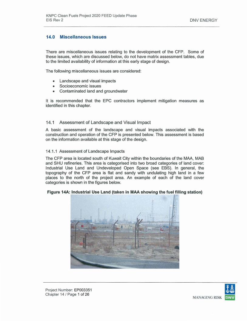
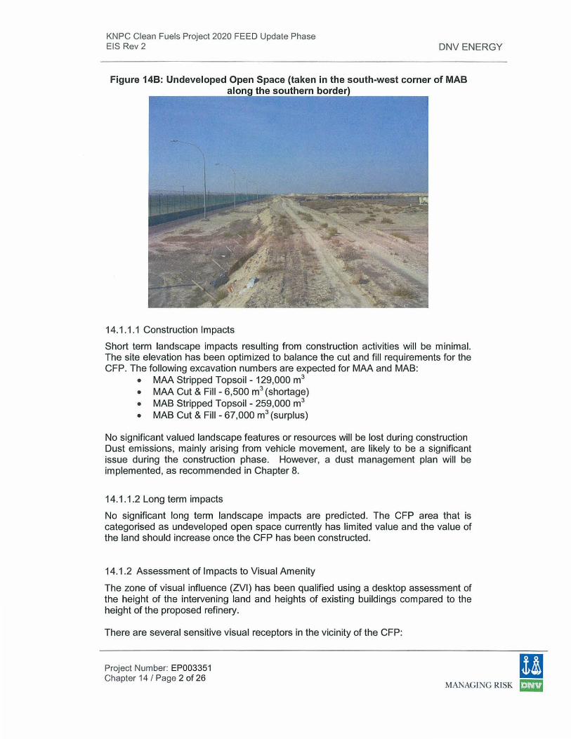
The CFP area is located south of Kuwait City within the boundaries of the MAA, MAB and SHU refineries. This area is categorised into two broad categories of land cover: Industrial Use Land and Undeveloped Open Space (see EBS). In general, the topography of the CFP area is flat and sandy with undulating high land in a few places to the north of the project area. An example of each of the land cover categories is shown in the figures below.
Figure 14A: Industrial Use Land (taken in MAA showing the fuel filling station) r
IJ Project Number: EP003351 Chapter 14 I Page 1 of 26
MANAGLNG RISK ~
KNPC Clean Fuels Project 2020 FEED Update Phase EIS Rev 2 DNV ENERGY
Figure 148: Undeveloped Open Space (taken in the south-west corner of MAB alon the southern bo
14.1.1.1 Construction Impacts
Short term landscape impacts resulting from construction activities will be minimal. The site elevation has been optimized to balance the cut and fill requirements for the CFP. The following excavation numbers are expected for MAA and MAB:
• MAA Stripped Topsoil- 129,000 m3
• MAA Cut & Fill - 6,500 m3 (shortage) • MAB Stripped Topsoil- 259,000 m3
• MAB Cut & Fill - 67,000 m3 (surplus)
No significant valued landscape features or resources will be lost during construction Dust emissions, mainly arising from vehicle movement, are likely to be a significant issue during the construction phase. However, a dust management plan will be implemented, as recommended in Chapter 8.
14.1 .1.2 Long term impacts
No significant long term landscape impacts are predicted. The CFP area that is categorised as undeveloped open space currently has limited value and the value of the land should increase once the CFP has been constructed.
14.1.2 Assessment of Impacts to Visual Amenity
The zone of visual influence (ZVI) has been qualified using a desktop assessment of the height of the intervening land and heights of existing buildings compared to the height of the proposed refinery.
There are several sensitive visual receptors in the vicinity of the CFP:
(I Project Number: EP003351 Chapter 14 I Page 2 of 26
MANAGiNG RISK ~
KNPC Clean Fuels Project 2020 FEED Update Phase EIS Rev 2
• Beach houses bordering the south-eastern boundary of MAB refinery. • Road #30 elevated to the west of the refineries
DNV ENERGY
• Fa ha heel suburb (approximately 51 ,210 people) to the north of MAA refinery • Um AI Haiman residential township (approximately 30,000 people) 1 km south of
MAB refinery.
The land surface around the project is relatively flat. Within the visual envelope, the main visual impact will be from the south. The key impacted areas will be the beach houses and the Um AI AI-Haiman residential township.
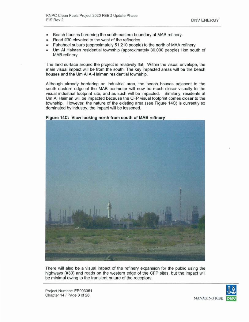
Although already bordering an industrial area, the beach houses adjacent to the south eastern edge of the MAB perimeter will now be much closer visually to the visual industrial footprint site, and as such will be impacted. Similarly, residents at Um AI Haiman will be impacted because the CFP visual footprint comes closer to the township. However, the nature of the existing area (see Figure 14C) is currently so dominated by industry, the impact will be lessened.
Fi ure 14C: View looki north from south of MAB refi
There will also be a visual impact of the refinery expansion for the public using the highways (#30) and roads on the western edge of the CFP sites, but the impact will be minimal owing to the transient nature of the receptors.
!I Project Number: EP003351 Chapter 14 / Page 3 of 26
MANAGING RISK ~
KNPC Clean Fuels Project 2020 FEED Update Phase EIS Rev 2
14.1 .2.1 Construction Impacts
DNV ENERGY
Visual impacts during construction will arise from views of the constructed plant as well as general construction activity. These will only cause a temporary change to the visual amenity. They will intrude into or impinge upon views from the south, east and west from nearby residential (village and coastal developments) and transport receptors and on views from other industrial developments.
14.1 .2.2 Long term impacts
Long term and visual impacts during operation will arise from views of the proposed refinery plant buildings and lighting. The existing refinery dominates many views and the proposed development fits within this established framework. At night the visual impact of lighting proposed for the extended refinery will be moderated as new lighting will be designed to minimize light spill into the surrounding landscape.
14.1.3 Mitigation of impact
The following mitigation measures will improve the visual impact of the development to be minimized as far as practical:
• Screening of construction and operation works by using hording or earth bunds (using surplus fill) , particularly at the refinery fence adjacent to the beach houses at south east of MAB. This may also provide additional benefit to reduce wind-blown dust and alleviate noise impacts.
• Site lighting is recommended to be designed and located to reduce off-site glare to a minimum and minimise the impact on visual amenity at night, having due regard to operational, emergency, security and safety requirements.
• Where possible, tone and colour treatment of plant structures should ensure that the development fits in with surroundings and will blend elements into the horizon and sky line when viewed from a distance e.g. the use of lighter colours on elevated structures and stacks to help reduce the prominence of skyline features and non-reflective paint throughout, where operationally possible.
14.1.4 Conclusions & Recommendations
There are no significant visual impacts from the CFP. From a distance, receptors will consider the refinery in context with the existing industrial developments adjacent to the site.
The proposed project is set in context with adjacent industrial areas where the visual environment is dominated by the existing refineries. Local observers will potentially
(I Project Number: EP003351 Chapter 14 I Page 4 of 26
MANAGING RISK ~
KNPC Clean Fuels Project 2020 FEED Update Phase EIS Rev 2 DNV ENERGY
be visually impacted by the new development, especially the beach houses on the south-eastern edge of the project and mitigation measures have been proposed to minimize visual impacts, in the form of hording or earth bunds using surplus spoil generated during construction.
The impact of the CFP development is minimized due to the CFP development being incorporated within the refinery boundaries.
14.2 Socio-economic Impact
This desk-based socio-economic impact review was completed based on the EBS, and a visit to the proposed CFP sites.
The review is a high-level review and is not based on detailed information. The identified socio-economic issues are shown in Table 14.1 below.
(I Project Number: EP003351 Chapter 14/ Page 5 of 26
MANAGING RISK ~
KNPC Clean Fuels Project 2020 FEED Update Phase EIS Rev 2
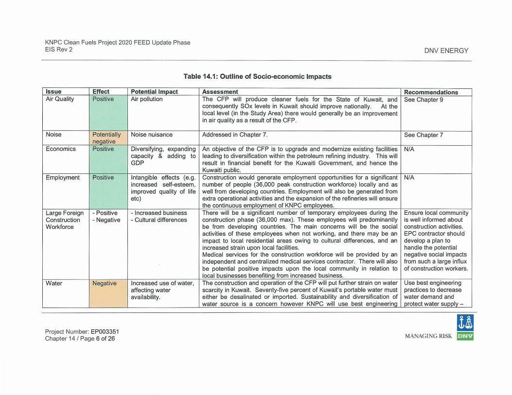
Table 14.1: Outline of Socio-economic Impacts
Issue Effect Air Quality Positive
Noise Potentially negative
Economics Positive
Employment Positive
Large Foreign -Positive Construction -Negative Workforce
Water Negative
Project Number: EP003351 Chapter 14 I Page 6 of 26
Potential Impact Assessment Air pollution The CFP will produce cleaner fuels for the State of Kuwait, and
consequently SOx levels in Kuwait should improve nationally. At the local level (in the Study Area) there would generally be an improvement in air quality as a result of the CFP.
Noise nuisance Addressed in Chapter 7.
Diversifying, expanding An objective of the CFP is to upgrade and modernize existing facilities capacity & adding to leading to diversification within the petroleum refining industry. This will GDP result in financial benefit for the Kuwaiti Government, and hence the
Kuwaiti public. Intangible effects (e.g. Construction would generate employment opportunities for a significant increased self-esteem, number of people (36,000 peak construction workforce) locally and as improved quality of life well from developing countries. Employment will also be generated from etc) extra operational activities and the expansion of the refineries will ensure
the continuous employment of KNPC employees. -Increased business There will be a significant number of temporary employees during the - Cultural differences construction phase (36,000 max). These employees will predominantly
be from developing countries. The main concerns will be the social activities of these employees when not working, and there may be an impact to local residential areas owing to cultural differences, and an increased strain upon local facilities. Medical services for the construction workforce will be provided by an independent and centralized medical services contractor. There will also be potential positive impacts upon the local community in relation to local businesses benefiting from increased business.
Increased use of water, The construction and operation of the CFP will put further strain on water affecting water scarcity in Kuwait. Seventy-five percent of Kuwait's portable water must availability. either be desa linated or imported. Sustainability and diversification of
water source is a concern however KNPC will use best engineering
DNV ENERGY
Recommendations See Chapter 9
See Chapter 7
N/A
N/A
Ensure local community is well informed about construction activities. EPC contractor should develop a plan to handle the potential negative social impacts from such a large influx of construction workers.
Use best engineering practices to decrease water demand and protect water supply-
!I MANAGING RISK ~
KNPC Clean Fuels Project 2020 FEED Update Phase EIS Rev 2
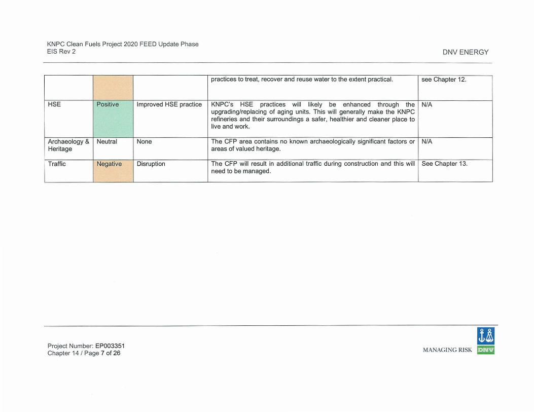
HSE Positive
Archaeology & Neutral Heritage
Traffic Negative
Project Number: EP003351 Chapter 14 I Page 7 of 26
Improved HSE practice
None
Disruption
DNV ENERGY
practices to treat, recover and reuse water to the extent practical. see Chapter 12.
KNPC's HSE practices will likely be enhanced through the N/A upgrading/replacing of aging units. This will generally make the KNPC refineries and their surroundings a safer, healthier and cleaner place to live and work.
The CFP area contains no known archaeologically significant factors or N/A areas of valued heritage.
The CFP will result in additional t raffic during construction and this will See Chapter 13. need to be managed.
(I MANAGING RISK tm
KNPC Clean Fuels Project 2020 FEED Update Phase EIS Rev 2
14.3 Contaminated Land & Groundwater
14.3.1 Contaminated Land
DNV ENERGY
In the EBS it was observed that there was no significant contamination identified at MAA and MAB, however, hydrocarbon levels were higher at SHU where contamination was identified at one location. The soil in this location will need to be carefully removed and disposed of correctly. lt is recommended that an independent Environmental Advisor is regularly on site during construction whilst soi l excavations are taking place to ensure that the soil is excavated and disposed of correctly, and to help identify any other areas of contamination.
The installation of CFP facilities has been planned with a minimum of underground process piping in accordance with current good engineering practices. There are no underground storage tanks in the CFP. Vessels, tanks and piping systems (including underground piping) will be hydro-tested before beginning operations to check for leaks. KNPC regularly inspects equipment for leakages as part of the EMS, in order to minimize the risk of contaminating land and I or groundwater during operations.
Additionally, the KISR study as discussed below in 14.3.2 also includes some investigation into contaminated land onsite.
14.3.2 Groundwater
14.3.2.1 Introduction
KISR conducted a study on behalf of KNPC in order to assess the groundwater pollution and potential for pollution caused by three KNPC refineries, namely MAA, Shuaiba and MAB (Impact on Oil Refineries on Groundwater Quality and Levels, Kuwait, WM021C, February 2009).
The assessment, as referenced in the aforementioned KISR report, followed the recognised systematic 3-level approach, commonly referred to as Phase I, 11 and Ill assessments, as below.
• Phase I - This phase identifies potential sources of contamination via a desk study using a remote sensing method, the land surface temperature (LST) method.
• Phase 11 - This phase installed a groundwater monitoring network though the drilling of 47 monitoring and testing wells across the 3 refineries. The monitoring system at MAA consists of 14 wells, at Shuaiba of 13 wells and at MAB of 18 wells. There are also 2 monitoring wells outside the refineries area. The monitoring wells installed are a mixture of multi-level wells specifically designed for contaminants sampling at
Project Number: EP003351 Chapter 14 I Page 8 of 26
(I MANAGING RISK ~
KNPC Clean Fuels Project 2020 FEED Update Phase EIS Rev 2 DNV ENERGY
selected depth, and dual purpose production/observation wells. The production/observation wells also allowed determination of the depth of the groundwater table at the well locations. Sampling of the well monitoring network was also conducted as part of this phase (with 260 samples taken) for selected chemical and bacteriological parameters.
• Phase Ill -A preliminary numerical groundwater hydrodynamic model was created, based on information from the previous phases of the study. lt was not possible to calibrate the model, as no time-series of groundwater levels were available for any of the sites. Instead, hypothetical contamination scenarios were assessed using literature values (for transport parameters required). Note that the model was also used to assess the applicability of pump-and-treat remediation.
The above are discussed, along with an outline of the methodology used in each phase, in more detail in the following sections. More details are available in the detailed KISR report on groundwater quality (WM021C, February 2009).
14.3.2.2 Phase I
14.3.2.2.1 Outline of Methodology
The remote sensing method was used to identify potential hydrocarbon contamination in the study area, and also to aid the selection of monitoring points across the study area.
Definition I delineation of potential hydrocarbon contamination was carried out using LST mapping. This method is based on the fact that various bodies can be differentiated by their thermal properties. For example, when a hydrocarbon spill mixes with soil, the soil composition will change, and so will its thermal properties. This will result in a higher than the background temperature signal. Therefore, mapping the temperature variations across a contaminated site can indicate the extent of the contamination. The preliminary investigations were carried out using IKONOS and RADARSAT data.
lt is also noted that the use of remote sensing data can provide an indication of drainage systems, topography and land use I cover in the study area. The results were used to aid the selection of the monitoring well locations for Phase 11, as it was assumed that contaminant transport in groundwater would follow existing pathways (i.e. drainage networks).
14.3.2.2.2 Results
A total of 13 sites of potential contamination were identified at MAA, 5 at Shuaiba and 12 at MAB. These are indicated in the figures that follow.
Project Number: EP003351 Chapter 14 I Page 9 of 26
I! MANAGING RISK ~
KNPC Clean Fuels Project 2020 FEED Update Phase EIS Rev 2 DNV ENERGY
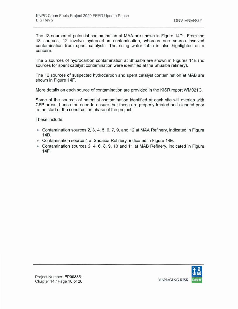
The 13 sources of potential contamination at MAA are shown in Figure 140. From the 13 sources, 12 involve hydrocarbon contamination, whereas one source involved contamination from spent catalysts. The rising water table is also highlighted as a concern.
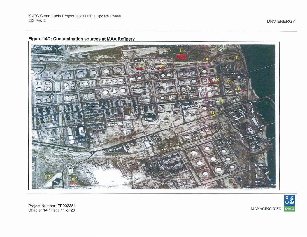
The 5 sources of hydrocarbon contamination at Shuaiba are shown in Figures 14E (no sources for spent catalyst contamination were identified at the Shuaiba refinery).
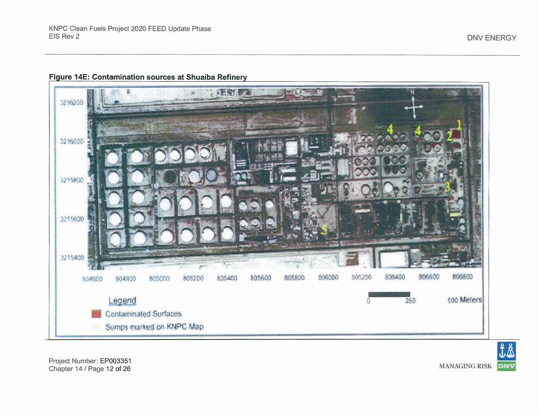
The 12 sources of suspected hydrocarbon and spent catalyst contamination at MAB are shown in Figure 14F.
More details on each source of contamination are provided in the KISR report WM021 C.
Some of the sources of potential contamination identified at each site will overlap with CFP areas, hence the need to ensure that these are properly treated and cleaned prior to the start of the construction phase of the project.
These include:
• Contamination sources 2, 3, 4, 5, 6, 7, 9, and 12 at MAA Refinery, indicated in Figure 140.
• Contamination source 4 at Shuaiba Refinery, indicated in Figure 14E. • Contamination sources 2, 4, 6, 8, 9, 10 and 11 at MAB Refinery, indicated in Figure
14F.
Project Number: EP003351 Chapter 14 I Page 1 0 of 26
I! MANAGING RISK ~
KNPC Clean Fuels Project 2020 FEED Update Phase EIS Rev 2
ure 140: Contamination sources at MAA Refine
Project Number: EP003351 Chapter 14 I Page 11 of 26
DNV ENERGY
11 MANAGING RISK ~
KNPC Clean Fuels Project 2020 FEED Update Phase EIS Rev 2
ure 14E: Contamination sources at Shuaiba Refine
~~~~!i~-.:J lle'J4 q,..J ev50oo ~(J~~t{l ao~oo at.t:~Gn<J $1l!aoo !!00000 ~Ct:J~'::I)
!:&gen~
C cr~tiwur'"''l t cc.t S~tr'fne<:s.
Surnpo5111Jrketl on KNPC Map
Project Number: EP003351 Chapter 14 I Page 12 of 26
0
DNV ENERGY
~t)
ll MANAGING RISK ~
KNPC Clean Fuels Project 2020 FEED Update Phase EIS Rev 2
Fiaure 14F: Contamination sources at MAB Refine
Project Number: EP003351 Chapter 14 I Page 13 of 26
1"'0,.-...;~
~.....,...__.'""'w ·-•r.., , ....
Mina JU:u:ll.,llah K......,_..
,_ ,...,.. __ ~-- ~
DNV ENERGY
I! MANAGING RISK ~
KNPC Clean Fuels Project 2020 FEED Update Phase EIS Rev 2
14.3.2.3 Phase 11
14.3.2.3.1 Outline of Methodology
DNV ENERGY
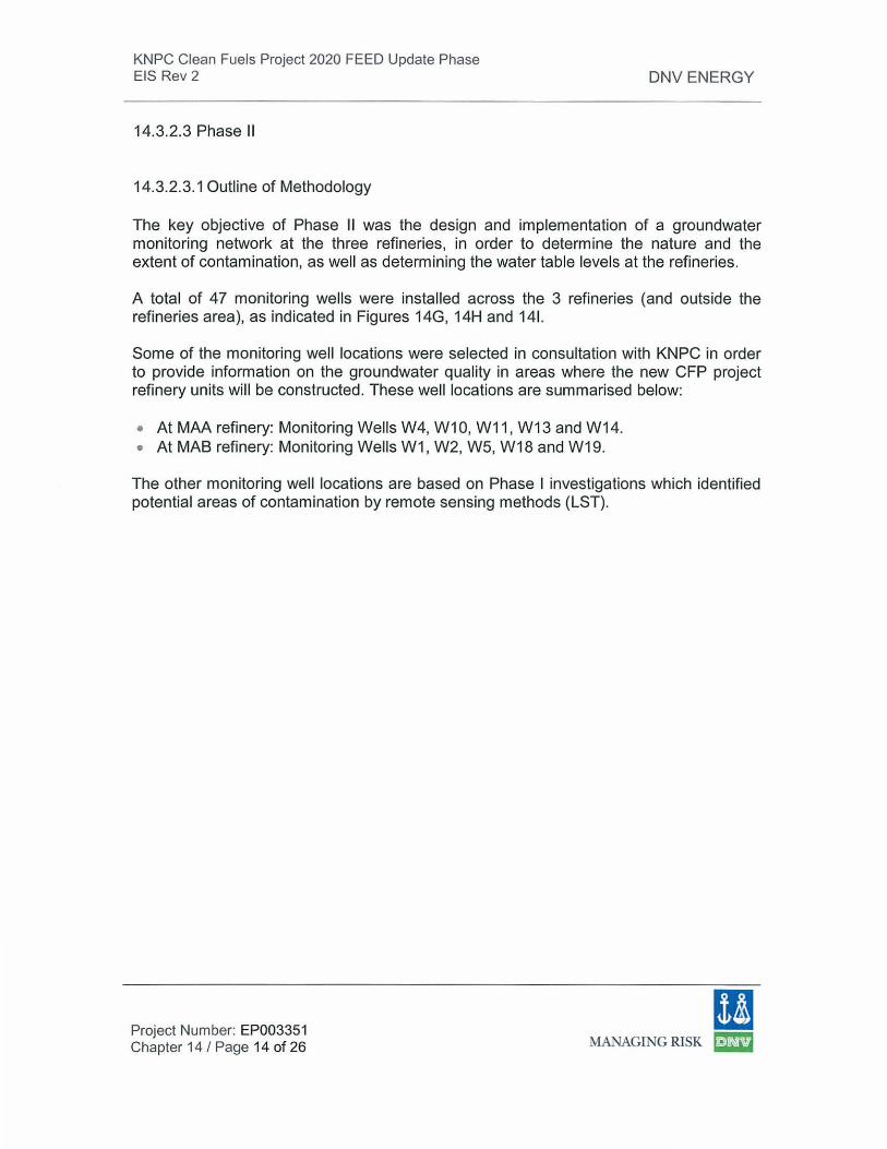
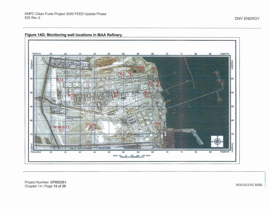
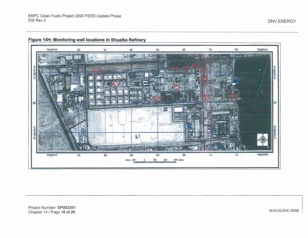
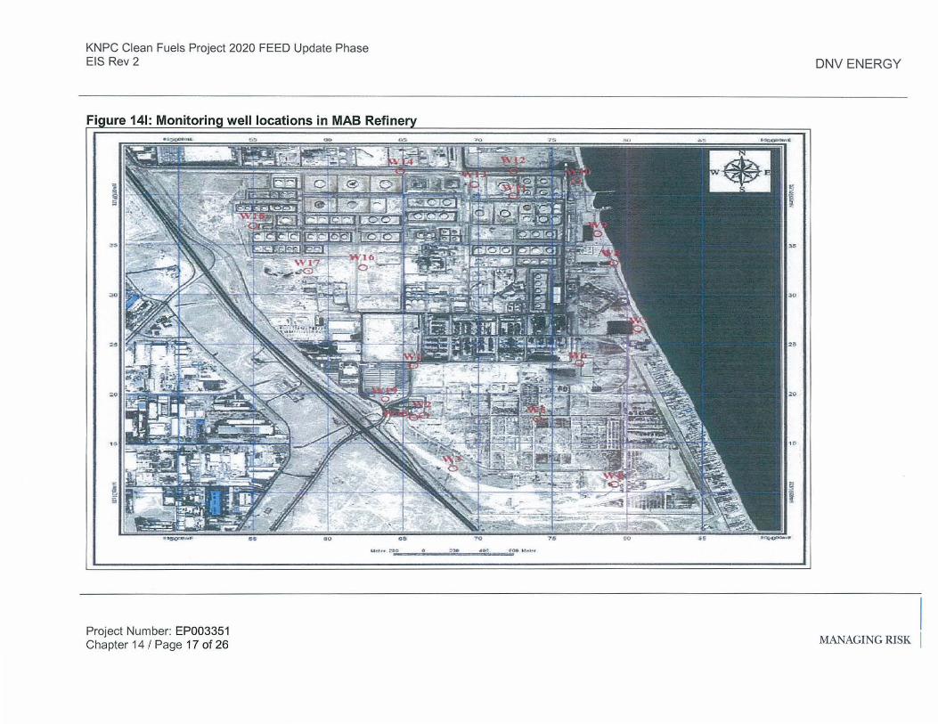
The key objective of Phase 11 was the design and implementation of a groundwater monitoring network at the three refineries, in order to determine the nature and the extent of contamination, as well as determining the water table levels at the refineries.
A total of 47 monitoring wells were installed across the 3 refineries (and outside the refineries area), as indicated in Figures 14G, 14H and 141.
Some of the monitoring well locations were selected in consultation with KNPC in order to provide information on the groundwater quality in areas where the new CFP project refinery units will be constructed. These well locations are summarised below:
• At MAA refinery: Monitoring Wells W4, W1 0, W11, W13 and W14. • At MAB refinery: Monitoring Wells W1 , W2, W5, W18 and W19.
The other monitoring well locations are based on Phase I investigations which identified potential areas of contamination by remote sensing methods (LST).
Project Number: EP003351 Chapter 14 I Page 14 of 26
I! MANAGING RISK ~
KNPC Clean Fuels Project 2020 FEED Update Phase EIS Rev 2
Fiaure 14G: Monitorina well locations in MAA Refine
Project Number: EP003351 Chapter 14 I Page 15 of 26
Mt:lar JDOCSJ::f loa ..00 ,., tlOiaf'
DNV ENERGY
MANAGING RISK
KNPC Clean Fuels Project 2020 FEED Update Phase EIS Rev 2
Fiaure 14H: Monitorina well locations in Shuaiba Refine
Project Number: EP003351 Chapter 14 I Page 16 of 26
Umr 1tlO
DNV ENERGY
0 200 4()0 1100 11.-
MANAGING RISK
KNPC Clean Fuels Project 2020 FEED Update Phase EIS Rev 2
Project Number: EP003351 Chapter 14 I Page 17 of 26
..,...., • • :,eo .o ~,. A OI'I ,_,. .,,.,.f<l
DNV ENERGY
MANAGING RISK
KNPC Clean Fuels Project 2020 FEED Update Phase EIS Rev 2 DNV ENERGY
In summary, the monitoring well network at MAA consists of 14 wells, at Shuaiba of 14 wells, and at MAB of 19 wells (the wells at Shuaiba and MAB refineries include 1 well off-site at each refinery).
14.3.2.3.2 Results
Water Table
One of the objectives of this phase was to obtain I measure the water table levels at the three refineries. At each monitoring well, KISR measured the depth of the water table below ground surface. These measurements are briefly outlined below for each refinery.
MAA Refinery:
• The minimum depth of the water table below ground surface was recorded at W1 (0.97 m), which is situated towards the seashore (and is around 2.1 m above the mean sea level).
• The depth of the water table below ground level for all the wells measured ranges from 0.97 m to 14 m.
Shuaiba Refinery:
• The minimum depth of the water table below ground surface was recorded at W6 (2.14 m), which is located approximately 7.6 m above the mean sea level.
• The depth of the water table below ground level for all the wells measured ranges from 2.14 m to 16.64 m.
MAB Refinery:
• The minimum depth of the water table below ground surface was recorded at W8 (1.95 m), which is located towards the seashore.
• The depth of the water table below ground level for all the wells measured ranges from 1.95 m to 22.58 m.
The KISR report indicates that the water table follows the general regional trend of flow in Kuwait.
Project Number: EP003351 Chapter 14 I Page 18 of 26
ll MANAGING RISK ~
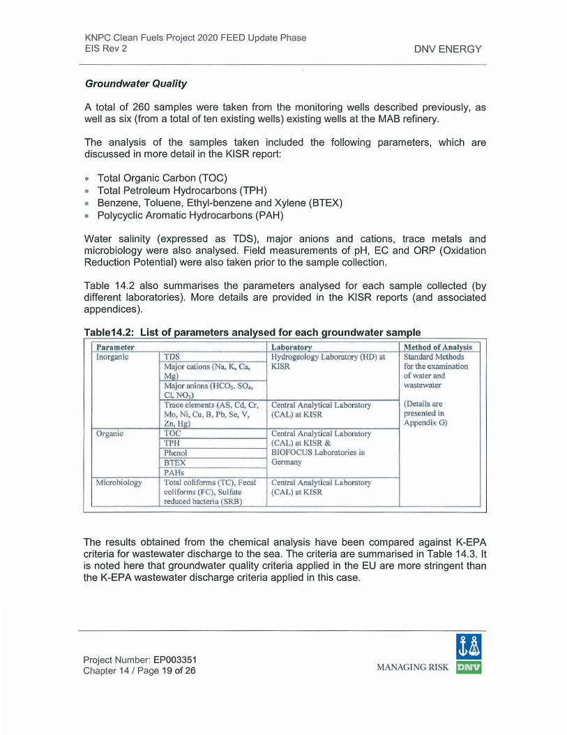
KNPC Clean Fuels Project 2020 FEED Update Phase EIS Rev 2
Groundwater Quality
DNV ENERGY
A total of 260 samples were taken from the monitoring wells described previously, as well as six (from a total of ten existing wells) existing wells at the MAB refinery.
The analysis of the samples taken included the following parameters, which are discussed in more detail in the KISR report:
• Total Organic Carbon (TOC) • Total Petroleum Hydrocarbons (TPH) • Benzene, Toluene, Ethyl-benzene and Xylene (BTEX) • Polycyclic Aromatic Hydrocarbons (PAH)
Water salinity (expressed as TDS), major anions and cations, trace metals and microbiology were also analysed. Field measurements of pH, EC and ORP (Oxidation Reduction Potential) were also taken prior to the sample collection.
Table 14.2 also summarises the parameters analysed for each sample collected (by different laboratories). More details are provided in the KISR reports (and associated appendices).
T bl 14 2 L" t f t a e IS o parame ers analyse df oreac h d t groun wa er sample Parameter Laborntory Me1hod of Analysis Inorganic TDS Hydrogeology Laboratory (HO) at Standard Methods
Major cations (Na, K, Ca, KISR for the examination M g) of water and Major anions (HCOh S04, wastewater Cl, N03) Trace elemertts (AS, Cd, Cr, Central Analytical Laboratory (Details are Mo, Ni. Cu, B, Pb, Se, V, (CAL) at KISR presented in Zn, Hg) Appendix G)
Organic TOC Central Analytical Laboratory TPH (CAL) at KISR & Phenol BIOFOCUS Laboratories in BTEX Germany PAHs
Microbiology Total coli forms (TC), Pecal Central Analyt ical Laboratory coli forms (FC), Sulfate (CAL) at KISR reduced bacteria (SRB)
The results obtained from the chemical analysis have been compared against K-EPA criteria for wastewater discharge to the sea. The criteria are summarised in Table 14.3. lt is noted here that groundwater quality criteria applied in the EU are more stringent than the K-EPA wastewater discharge criteria applied in this case.
Project Number: EP003351 Chapter 14 I Page 19 of 26
I! MANAGING RISK ~
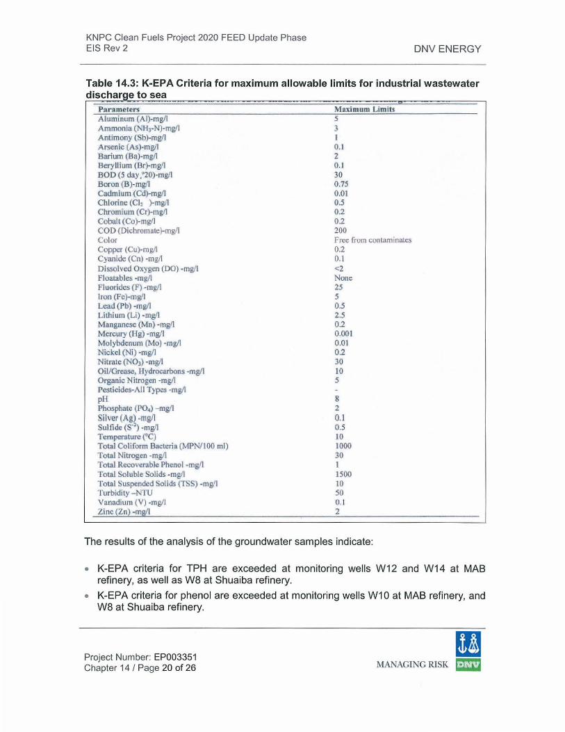
KNPC Clean Fuels Project 2020 FEED Update Phase EIS Rev 2 DNV ENERGY
Table 14.3: K-EPA Criteria for maximum allowable limits for industrial wastewater dischar e to sea
Parameters AJuminum (Al)-mgll Ammonia (l'H1-N)-mgll Antimony (Sb}-mgll Arsenic (As)-mg/1 Barium (Ba)-mg/1 Berylli um (Br)-mg/1 BOD (5 day •0 20)-mg/1 Boron (B)-mg/1 Cadmi um (Cd}-rng/1 Chlorine (Ch )-mg/1 Chromium (Cr)-mgll Cobalt (Co)-mWJ COD (Dichromate}-mgll Col or Copper (Cu)-mg/1 Cyanide (Cn) -mg/1 Dissolved Oxygen (DO) -mg/1 Floatables ·mg/1 Fluorides (f') -mg/1 lron (Fc)·mg/1 Lead (Pb) -mg/1 Lithium (Li) ·mgll Manganese (Mn) · mgl! Mercury (I I g) -mg/1 M olybdenum (Mo) -mg/1 Nickel (Ni) -mg/1 Nitrate (NOl ) · mg/1 Oil/ Grease, llydtocarbons ·mg/1 Organic N itrogcn -mg/1 Pesticides-All Types -mg/1 pH Phosphate (P04) -mg/1 Silver (Ag) -mg/1 Sulfide (S'2) ·mg/1 Temperature f C) Tobl Coliform Bacteria (MPN/ 100 ml) Total Nitrogen ·mg/1 Total Recoverable Phenol -mg/1 Total Soluble Solids ·mg/1 Total Suspended Solids (TSS) -msfl Turbidity - NTU Vanadium (V) -mgll Zinc (Zn} -mg/1
M aximum Limits, 5 3 1 0.1 2 ll I 30 0.7!i 0.01 0.5 02 02 200 Free from cunwm in~es 0.2 0.1 <2 None 25 5 0.5 2.5 0.2 0.001 0 .01 0.2 30 10 5
8 2 0.1 0.5 10 1{}00 30 I 1500 10 50 0.1 2
The results of the analysis of the groundwater samples indicate:
• K-EPA criteria for TPH are exceeded at monitoring wells W12 and W14 at MAB refinery, as well as W8 at Shuaiba refinery.
• K-EPA criteria for phenol are exceeded at monitoring wells W1 0 at MAB refinery, and W8 at Shuaiba refinery.
Project Number: EP003351 Chapter 14 I Page 20 of 26
11 MANAGING RISK ~
KNPC Clean Fuels Project 2020 FEED Update Phase EIS Rev 2 DNV ENERGY
• In a number of other wells, K-EPA criteria for faecal coliform bacteria are exceeded. These high bacteria concentrations were detected at MAB wells W3, W4, W12 and W17, Shuaiba wells W2, W3 and W7 and MAA wells W1 , W2, W4 and W5. Sulphate reducing bacteria (SRB) were also detected in wells at all refineries. Note that these bacteria under anaerobic conditions may result in hydrogen sulphide release (through reduction of the sulphate ion in the groundwater to sulphide ion).
• High levels of solute concentrations that exceed K-EPA criteria (i.e. the major anions I cations summarised in Table 14.2, such as Na+, K+, S042
-, er etc), have been detected at all three refineries.
• High levels of boron (which is relatively non-toxic in elemental form), exceed K-EPA relevant criteria, were detected at all well samples from MAB refinery, at Shuaiba wells W6 and W12, and at MAA wells W2, W3, W4 and W5.
• Low levels of Chromium, below K-EPA's relevant criteria, were detected at MAB well W4.
• Selenium was detected at Shuaiaba wells W6 and W12 (0.06 to 0.2 mg/1). There are no K-EPA criteria for Selenium, though it is relatively non-toxic (only toxic if taken in excess).
• High levels of Molybdenum (it is noted that acute toxicity has not been observed in humans), exceeding K-EPA's relevant criteria, were detected at MAB wells W4 and W14, Shuaiba wells W6 and W12, and MAA wells W4 and W5.
Project Number: EP003351 Chapter 14 I Page 21 of 26
(I MANAGING RISK ~
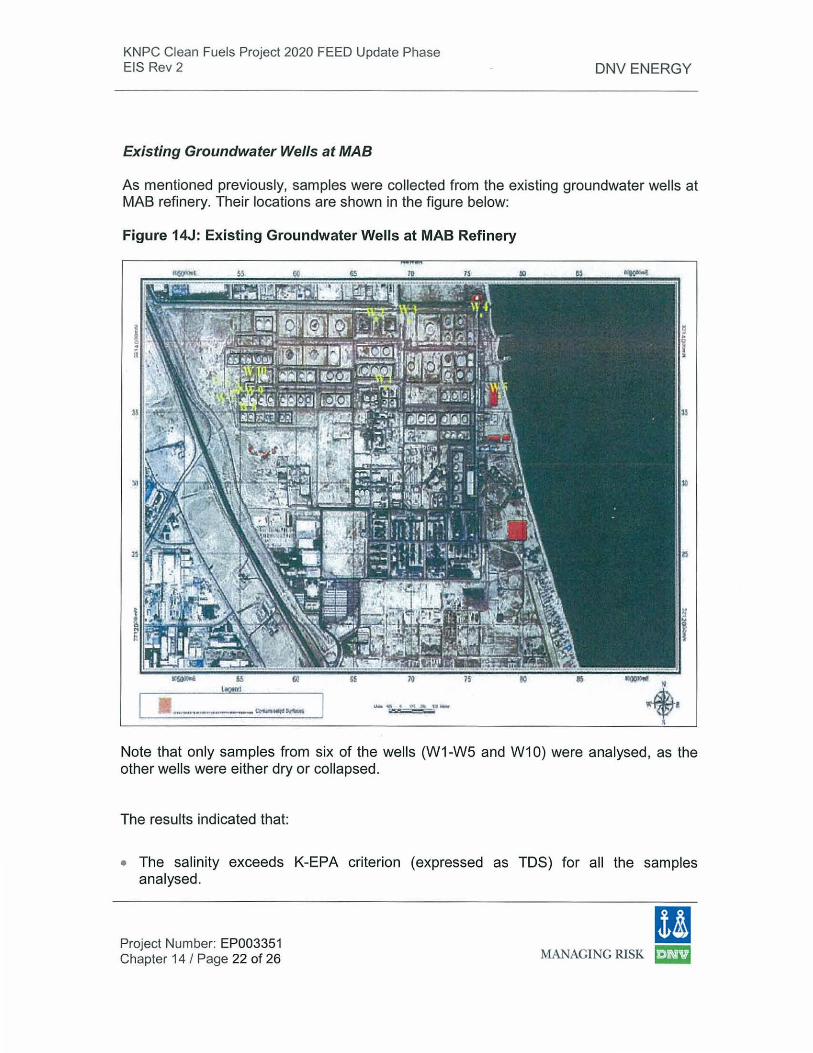
KNPC Clean Fuels Project 2020 FEED Update Phase EIS Rev 2
Existing Groundwater Wells at MAB
DNV ENERGY
As mentioned previously, samples were collected from the existing groundwater wells at MAB refinery. Their locations are shown in the figure below:
Figure 14J: Existing Groundwater Wells at MAB Refinery
Note that only samples from six of the wells (W1-W5 and W10) were analysed, as the other wells were either dry or collapsed.
The results indicated that:
• The salinity exceeds K-EPA criterion (expressed as TDS) for all the samples analysed.
Project Number: EP003351 Chapter 14 I Page 22 of 26
(I MANAGING RISK ~
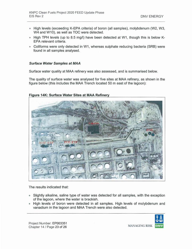
KNPC Clean Fuels Project 2020 FEED Update Phase EIS Rev 2 DNV ENERGY
• High levels (exceeding K-EPA criteria) of boron (all samples), molybdenum (W2, W3, W4 and W1 0), as well as TOC were detected.
• High TPH levels (up to 8.5 mg/1) have been detected at W1 , though this is below KEPA relevant criteria.
• Coliforms were only detected in W1, whereas sulphate reducing bacteria (SRB) were found in all samples analysed.
Surface Water Samples at MAA
Surface water quality at MAA refinery was also assessed, and is summarised below.
The quality of surface water was analysed for five sites at MAA refinery, as shown in the figure below (this includes the MAA Trench located 50 m east of the lagoon):
Fi ure 14K: Surface Water Sites at MAA Refine
The results indicated that:
• Slightly alkaline, saline type of water was detected for all samples, with the exception of the lagoon, where the water is brackish.
• High levels of boron were detected in all samples. High levels of molybdenum and vanadium in the lagoon and MAA Trench were also detected.
Project Number: EP003351 Chapter 14 I Page 23 of 26
ID MANAGING RISK ~
KNPC Clean Fuels Project 2020 FEED Update Phase EIS Rev 2 DNV ENERGY
• High levels of TOC and TPH were detected for the lagoon and MAA Trench samples. • The MAA Trench sample results indicate high levels of microbial contamination. • The lagoon sample indicates the presence of PAH.
The salinity (expressed as TDS) and TPH for the lagoon and MAA Trench are exceeding the K-EPA criteria used for the purposes of this study. This also applies for molybdenum and vanadium parameters. lt is also noted that leakage from the lagoon might be responsible for the water content contamination in the MAA Trench.
14.3.2.4 Phase Ill
14.3.2.4.1 Outline of Methodology
The main objective of Phase Ill was to identify the main aquifer type in the area and setup a 3-D model for the aquifer underlying the refineries using available field information. Additionally, to characterise the contamination plume and to develop a plan for remediation of the aquifer (and prevent further future pollution).
The approach followed is briefly outlined below:
• Analyse available drilling data and develop a conceptual geologic and hydrogeologic model.
• Perform pump-and-treat scenarios and run hypothetical (i.e. based on literature values for transport parameters) plume simulation to assess the shape and speed of its spread.
14.3.2.4.2 Results
lt is noted that the modelling work is based on available information at the time of the study (and would benefit from sustained and continuous monitoring data).
The key findings from this part of the study are briefly summarised below:
• The time of travel from potential sources of contamination to sea was found to be around 40 days for seaside sources and 24 years for inland sources (based on the particle tracking method).
• Complete interception of the release particles is possible at pumping rates of approximately 120 m3/day.
• Hypothetical simulations of contaminant releases using literature values of transport parameters shows relative containment of the pollutant plume (even after 50 years from release).
Project Number: EP003351 Chapter 14 I Page 24 of 26
I! MANAGING RISK ~
KNPC Clean Fuels Project 2020 FEED Update Phase EIS Rev 2
14.3.2.5 Conclusions and Recommendations
DNV ENERGY
Determination of possible leakage from specific tank bottoms causing groundwater contamination has not specifically been addressed by the KISR report because this would require close physical examination of each of the tanks (and tank bunds), accompanied by groundwater investigations in the immediate vicinity of each tank (there is a large number of tanks in the refineries, hence large volume of wells I samples would be required).
However, several sources and areas of groundwater contamination have been identified at the refineries. Recommendations for treatment, remediation and preventive measures have been made in the KISR report. These include decommissioning all unlined pits, with the soil beneath them excavated, followed by the removal of free moving solutes from groundwater sources by pump and treat for a limited duration. More details are provided in the Overall Conclusions and Recommendations section of the KISR report.
The KISR report identifies (based on comparison against K-EPA wastewater discharge standards) that the groundwater below the refineries is contaminated in some areas by parameters such as TPH, phenol, coliform bacteria, trace elements such as boron and molybdenum, as well as major anions and cations (i.e. the major anions I cations summarised in Table 14.2, such as Na+, K+, S042
-, er etc, which are likely to originate from infiltration of seawater into groundwater). Bacteria (e.g. coliform) contamination suggests the leakage I discharge of sewage to groundwater.
The refineries may be responsible for some of the contamination. Note that groundwater quality criteria applied in the EU are more stringent than the K-EPA wastewater discharge criteria.
lt is not the intention of this EIA for the CFP to deal with this historical groundwater contamination, as this EIA deals only with the CFP scope. But the CFP development does need to be considered in the context that existing refinery design and operation has probably resulted in groundwater contamination.
The KISR report has recommended treatment, remediation and preventive measures. lt is DNV's consideration that any future risk of groundwater contamination by the CFP will be additionally reduced by improved environmental management of the refinery facilities, via:
• Regular checks for fugitive emissions to groundlgroundwater from CFP refinery plant and tanks included as part of the EMS;
• Systematic groundwater monitoring and analysis (against agreed criteria) around the CFP facilities and in the vicinity of the tank farms;
• The CFP has satisfactory wastewater and sewage treatment facilities planned during normal operation - see Chapter 12 - but it is important that EPC contractors implement sufficient and adequate wastewater and sewage
Project Number: EP003351 Chapter 14 I Page 25 of 26
(I MANAGING RISK mE!3
KNPC Clean Fuels Project 2020 FEED Update Phase EIS Rev 2 DNV ENERGY
treatment/handling facilities at the earliest stages of construction to ensure that CFP does not exacerbate groundwater contamination.
Additionally, soil and groundwater has been identified in the KISR report as contaminated in locations that overlap with the CFP development. lt is recommended that:
• Groundwater encountered during CFP excavation activities is contained and collected onsite and tested to meet K-EPA requirements (TPH, Phenol & coliforms) before discharge via existing storm water discharge outlets at MAA or MAB. If the water quality is not acceptable, the EPC contractor will need to provide means for treating the water prior to discharge.
• Potential soil contamination sources identified in the KISR report that overlap with CFP areas are properly remediated prior to the start of the construction phase of the CFP project. These may include:
• Contamination sources 2, 3, 4, 5, 6, 7, 9, & 12 at MAA Refinery, indicated in Figure 140.
• Contamination source 4 at Shuaiba Refinery, indicated in Figure 14E. • Contamination sources 2, 4, 6, 8, 9, 10 and 11 at MAB Refinery,
indicated in Figure 14F.
Project Number: EP003351 Chapter 14 I Page 26 of 26
I! MANAGING RISK ~
KNPC Clean Fuels Project 2020 FEED Update Phase EIS Rev 2
15.0 Emergency Response Plan
15.1 Introduction
DNV ENERGY
The CFP involves the upgrading and modernization of KNPC's existing refinery operations at MAA, MAB and SHU. Since these refineries are currently being operated by KNPC, all of KNPC's policies and procedures will apply to the CFP including the KNPC Major Incident Procedure Plan {MIPP). MIPP is one of KNPC's Emergency Plans that provides a procedural framework for responding to emergency incidents such as fire or a flammable/toxic release.
The sections outlined in this chapter have been abstracted from the MIPP. They are set out and adapted here to demonstrate how an Emergency Response Plan (ERP) would be implemented for the CFP. The information given in this chapter is for general guidance only. The controlled version of the MIPP is available on KNPC intranet. MIPP call-out lists for CFP areas will be developed and role players will be trained before commissioning.
The KNPC refineries and marine terminals, within which the CFP will operate, process, store and distribute large quantities of flammable and toxic materials. An incident, such as fire, explosion or gas release occurring at these sites may have serious consequences, affecting not only the incident site but industries and the public outside the site boundaries as well, which could result in loss of lives and property, and damage to the environment, business and reputation.
KNPC is committed to the safety of its employees, installations and the public. All applicable safety standards, procedures and best practices are followed during process selection, design, construction and operation of various facilities . However, even with the safest working practices, emergency incidents may occur. Therefore, it is imperative that the CFP has an adequate level of 'Emergency Preparedness' to deal with any such incident effectively and efficiently, thereby minimizing the consequences.
Emergency Preparedness includes the following integral components:
• Prevention and mitigation: to eliminate or reduce the chances or lessen the effects of an emergency, for example, by adopting safe design, operating and maintenance practices.
• Emergency plans: written procedures and guidelines on how to respond efficiently and effectively, with the right resources and trained personnel, should an emergency occur.
• Response: activities immediately following the alert or disaster.
• Restoration: returning all used I affected systems and services to normality as soon as practicable after the emergency has been resolved and any adverse impacts mitigated.
The MIPP is one of KNPC's principal emergency plans. lt provides a procedural framework for responding to emergency incidents such as fire and flammable I toxic releases. MIPP was initially conceived to ensure a unified and collective KNPC approach for responding to emergencies at its refineries and associated oil terminals, and to replace a number of the individual ERPs previously followed at various sites.
Project No: EP003351 Chapter 15 I Page 1 of 23
!I MANAGING RISK f23
KNPC Clean Fuels Project 2020 FEED Update Phase EIS Rev 2 DNV ENERGY
MIPP is supplemented by the KNPC Security Manual and the site specific plans which include call-out lists and the Site Emergency Evacuation Plan (SEEP). KNPC's Crisis Management Plan will be activated in case of an emergency identified as 'crisis' which requires direct involvement of KNPC corporate management.
15.2 MIPP: Purpose and Scope
15.2.1 Purpose
The purpose of KNPC's MIPP is to provide a simple, logical and comprehensive procedural framework to ensure:
• The overall direction of efforts to bring the emergency under control and restore the affected site to normal operation as soon as possible.
• The organisation and coordination of effective action, making the most efficient use of available resources, in order to ensure:
• Safety of personnel; • Minimum damage to KNPC plants and equipment; • Protection of both property outside the affected refinery and the
environment.
• Those personnel who may be involved in a KNPC site emergency incident fully understand their role, and the roles of others, in effectively dealing with the incident.
15.2.2 Scope
The CFP will be incorporated into the scope of KNPC's MIPP, which currently covers the following:
• Procedure for notifying emergencies, categorization and mobilizing emergency response.
• Emergency handling organization and coordination centres • Guidelines for developing emergency call-out lists and SEEPs by sites. • Roles and responsibilities of the key role players, emergency
control/coordination centres, called-out personnel and external agencies likely to be involved.
• Any credible incident occurring on one of the above KNPC sites, which could for example, involve:
• Injuries to personnel; • Release of flammable gas or other materials leading to a fire or
potential fire; • Effects of an explosion;
• Release of toxic materials such as hydrogen sulphide, chlorine or ammonia to the atmosphere from either a KNPC or adjacent industrial site;
• A major pollution incident or spillage within the confines of one of the above KNPC sites or their immediate surroundings;
Project No: EP003351 Chapter 15 I Page 2 of 23
ll MANAGING RISK ~
KNPC Clean Fuels Project 2020 FEED Update Phase EIS Rev 2 DNV ENERGY
• Security incidents/threats received through Telephone, fax, email, in person, through media or any other means;
• Bomb threat, Suspicious packages or devices and Weapons/explosives within KNPC facilities;
• Hijack or hostile boarding of a ship at marine terminals;
• Security breaches.
• The interactions between KNPC personnel and outside emergency services (and other bodies) involved in the KNPC MIPP, including:
• Public Authority for Industries (PAl);
• Kuwait State Fire Brigade (KSFB); • Kuwait State Security Force (KSF);
• Kuwait State Civil Defence Force (KCDF);
• Kuwait State Installations Security Force (KISF); • Vital & Oil Installations Protection Department (VOIPD)
• KPC-Incident Management Team (KPC-IMT);
• Kuwait Environment Public Authority (K-EPA); • Kuwait Municipality.
• Port Facility Security Officer (PFSO)
• KOC Export & Marine Operations Group (E&MOG)
15.2.3 Reference Emergency Plans and Procedures
A number of Reference Emergency Plans and Procedures are also relevant to the application and implementation of KNPC's MIPP, as follows:
KNPC:
• KNPC Crisis Management Plan (SHE-TSFP-08-2208);
• Security Manual 2007
• KNPC Smart SMS Service for MIPP Call-out (SHE-TSFP-07-2210)
• Site Emergency Evacuation Plans (SEEP);
• Medical Emergency Plan (SHE-MDMA-07-2208)
• Guidelines for MIPP Drills
• Procedure on Environmental Communication (SHE-ESHU-03-1403);
15.3 MIPP: Outline
15.3.1 Overview
All emergencies are reported to KNPC's Emergency Communications Control Centre (ECCC). The ECCC takes action to mobilize the Emergency Response Teams (ERT) and makes personnel call-outs as necessary. The Public Authority for Industry Emergency Control Centre (PAIECC) makes the call-out for assistance from external
Project No: EP003351 Chapter 15 I Page 3 of 23
I! MANAGING RISK I:::E!3
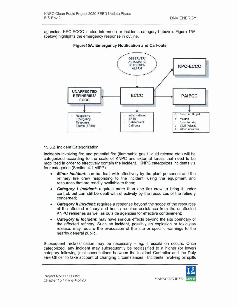
KNPC Clean Fuels Project 2020 FEED Update Phase EIS Rev 2 DNV ENERGY
agencies. KPC-ECCC is also informed (for incidents category-! above). Figure 15A (below) highlights the emergency response in outline.
Figure15A: Emergency Notification and Call-outs
Respective Emergency Response Teams (ERTs}
15.3.2 Incident Categorization
ECCC
Initial call-{)ut ERTs Subsequent Gaii-{)Uts
KPC-ECCC
PAIECC
o State Fire Brigade
o VOIPD o State Security o Civil Defence o Other Industries
Incidents involving fire and potential fire (flammable gas /liquid release etc.) will be categorized according to the scale of KNPC and external forces that need to be mobilized in order to effectively contain the incident. KNPC categorizes incidents via four categories (Section 4.1 MIPP):
• Minor Incident: can be dealt with effectively by the plant personnel and the refinery fire crew responding to the incident, using the equipment and resources that are readily available to them;
• Category I Incident requires more than one fire crew to bring it under control , but can still be dealt with effectively by the resources of the refinery concerned;
• Category //Incident requires a response beyond the scope of the resources of the affected refinery and hence requires assistance from the unaffected KNPC refineries as well as outside agencies for effective containment;
• Category Ill Incident may have serious effects beyond the site boundary of the affected refinery. Such an incident, possibly an explosion or toxic gas release, may require the evacuation of the site or specific warnings to the nearby general public.
Subsequent reclassification may be necessary - eg. if escalation occurs. Once categorized, any incident may subsequently be reclassified to a higher (or lower) category following joint consultations between the Incident Controller and the Duty Fire Officer to take account of changing circumstances. Incidents involving oil spills
Project No: EP003351 Chapter 15 I Page 4 of 23
11 MANAGING RISK l:m3
KNPC Clean Fuels Project 2020 FEED Update Phase EIS Rev 2 DNV ENERGY
shall be additionally classified as per the Oil Spill Response Plan (Section 11 MIPP) for the purpose of containment and recovery of oil spills (see Section 15.3.4, below). Incidents are categorized according to type (fire, gas release, oil spill, etc.) and severity in order to determine the scale of response necessary to control it.
Emergency response levels are as follows:
1. Resources readily available at I near incident location
2. Resources available at the affected refinery
3. Support from unaffected refineries
4 . External support (government agencies, mutual aid companies etc.)
15.3.3 Offsite Emergency Plan
This section describes KNPC response to the off-site emergency situations, for example:
• An on-site process incident (fire, explosion or hazardous material release with potential to affect the neighbouring community and industries, causing harm to the property, health and environmental).
• An incident involving KNPC facilities off-site (e. g. IRT lines within Public Authority for lndustry-Shuaiba area, KNPC lines passing through PlC, area and the underground and submarine pipelines from refineries to the oil piers).
• A situation where KNPC facilities are not involved, but KNPC management decided to respond to provide requested assistance for another company's incident.
Offsite Emergencies Caused by On-site process incidents
• _Community Safety: An on-site process incident which may have serious effects beyond the site boundaries is categorized as a category-Il l incident (section 4). Kuwait Civil Defence, called-in through PAIECC to initiate appropriate action for the safety of the affected community in coordination with the local Civil Administration. Civil Defence will activate the civil defence siren (Alert/Evacuation/All-clear) for the affected area, if necessary. Incident close-out at KNPC site will be done in consultation with Civil Defence in such case.
• Neighbouring Industries: Alerting and emergency coordination with the neighbouring industries is done through PAIECC. In addition, the following direct communication procedures exist:
1. Emergency coordination procedures between KNPC and PlC (6 MIPP Annexure- 6).
2. Normal and emergency communication between KNPC MAA Refinery
Project No: EP003351 Chapter 15 I Page 5 of 23
(I MANAGING RISK ~
KNPC Clean Fuels Project 2020 FEED Update Phase EIS Rev 2 DNV ENERGY
• Environmental complaints: (Oil spill, odours etc.) from outside parties are received at ECCC-MAB. Further actions are initiated to address the situation in accordance with the document Procedure on Environmental Communication. Response oil spills is covered in MIPP sections 10 and 11.
Emergencies involving Off-site KNPC Facilities
Emergencies involving KNPC facilities in PAl (Shuiaba) Area and KNPC pipelines passing through PlC area are outlined in MIPP section 4.6 and Annexure 6 respectively
KNPC Response to Other Companies' Incidents
KNPC as a member of the KPC Incident Management Team for oil spill incidents, will respond with its Oil Spill Response Teams and resources to the land oil spill incidents in K-companies when required as per the KPC Oil Spill Contingency Plan.
KNPC response and resource support to other types of incidents shall be decided by KNPC management based on the request received from the affected companies management.
15.3.4 Corporate Crisis Management
In case of emergency situations (triggered by internal or external cause) which might be beyond the capability and authority of the KNPC site management to handle and require involvement of the KNPC top management for strategic directives, coordination with KPC and other national and international agencies, are classified as crisis. A provisional Crisis Management Plan (SHE-TSFP-08-2208) has been developed for managing the crises.
15.3.5 Emergency Communication and Alarm Systems
There are four principal avenues of communication available during an emergency. Each of these systems is discussed below.
1. Telecommunication facilities
• Radios: Trunking Radio System (TRS) consisting of channels for emergency as well as normal work communication.
• Telephones: Various internal and external permutations • KNPC Smart SMS Service for M/PP Call-out: Implemented to make
emergency callout by sending SMS messages to MIPP role players. • Pagers: Some employees have been provided with personal pagers to
enable them to be called-in when needed.
2. Public Address and Plant Paging • Public Address: One-way PA system from ECCC Operator to outlets in
plant operations control rooms, Medical Centre, MCC, RCC and other buildings.
Project No: EP003351 Chapter 15 I Page 6 of 23
11 MANAGING RISK ~
KNPC Clean Fuels Project 2020 FEED Update Phase EIS Rev 2 DNV ENERGY
• Plant Paging System: Process Unit areas have been provided with Plant Paging System for communication between control rooms and field.
3. Fire/Gas Detectors and Alarms • Fire Detectors: Different types of fire detectors and associated alarm
systems have been installed in various facilities • Break Glass Fire Alarm Points: Break glass type fire alarm points are
available through out the premises for manual notification of any incident. • Fire Alarm Panels: Fire alarm panels and graphic display panels have
been installed in the ECCC located at the fire stations in each refinery and at control buildings of the marine terminals
• Fixed Gas Detectors: Fixed continuous hydrogen sulphide (HzS) and Hydrocarbon detectors are installed in certain high risk locations for atmospheric H2S monitoring.
• Portable and Personal Detectors: Adequate number of personal H2S detectors and portable gas detector/alarms have been provided to the field operations and maintenance personnel to warn them.
4. Emergency Sirens • Refineries Emergency Sirens: All three refineries follow a three tone
emergency siren system. • Civil Defence Siren System: The KCDF sirens are located both on-site
and off-site. These are actuated by KCDF in case of national emergency.
15.3.6 Emergency Control and Coordination Centres
The following various Emergency Control and Coordination Centres are set-up according to an initial assessment of requirements (as shown in Figure 158):
• A Forward Control Unit (FCU) is set up close to the Incident Scene to manage emergency control activities. In case of land oil-spill incidents, an Oil Spill Response Vehicle (OSRV) will be mobilized and established at a strategic location near the incident. The FCU may be subsequently withdrawn following a joint decision by the Refinery Shift Leader and the Oil Spill Response Team Leader.
• A Resource Coordination Centre (RCC) to ensure adequate provisions of necessary materials and manpower resources are effectively and speedily mobilised.
• A Management Co-ordination Centre (MCC) to provide overall coordination of the emergency response efforts, to interface with the government, regulatory and other outside agencies, and to deal with enquiries from the press and the public.
Project No: EP003351 Chapter 15 I Page 7 of 23
ll MANAGING RISK ~
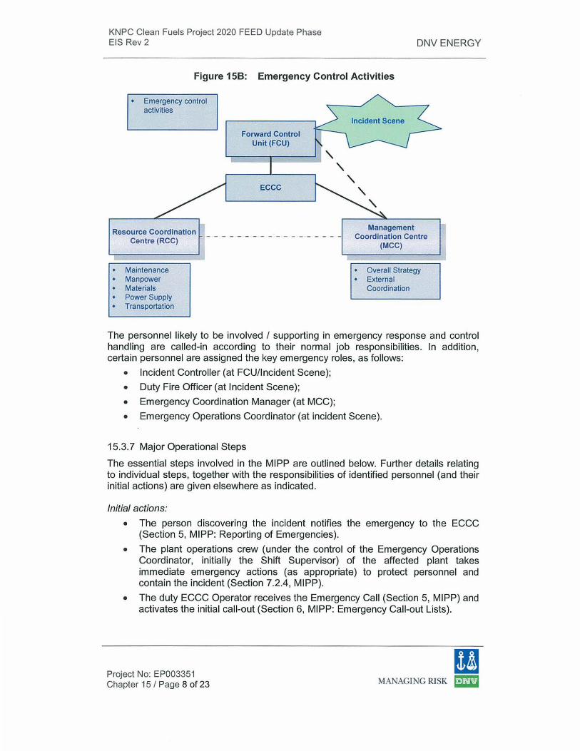
KNPC Clean Fuels Project 2020 FEED Update Phase EIS Rev 2 DNV ENERGY
Figure 158: Emergency Control Activities
• Emergency control activities
Resource Coordination Centre (RCC)
• Maintenance • Manpower • Materials • Power Supply • Transportation
Forward Control Unit (FCU)
ECCC
Management Coordination Centre
(MCC)
• Overall Strategy • External
Coordination
The personnel likely to be involved I supporting in emergency response and control handling are called-in according to their normal job responsibilities. In addition, certain personnel are assigned the key emergency roles, as follows:
• Incident Controller (at FCU/Incident Scene);
• Duty Fire Officer (at Incident Scene);
• Emergency Coordination Manager (at MCC);
• Emergency Operations Coordinator (at incident Scene).
15.3. 7 Major Operational Steps
The essential steps involved in the MIPP are outlined below. Further details relating to individual steps, together with the responsibilities of identified personnel (and their initial actions) are given elsewhere as indicated.
Initial actions:
• The person discovering the incident notifies the emergency to the ECCC (Section 5, MIPP: Reporting of Emergencies).
• The plant operations crew (under the control of the Emergency Operations Coordinator, initially the Shift Supervisor) of the affected plant takes immediate emergency actions (as appropriate) to protect personnel and contain the incident (Section 7.2.4, MIPP).
• The duty ECCC Operator receives the Emergency Call (Section 5, MIPP) and activates the initial call-out (Section 6, MIPP: Emergency Call-out Lists).
Project No: EP003351 Chapter 15 I Page 8 of 23
(! MANAGING RISK ~
KNPC Clean Fuels Project 2020 FEED Update Phase EIS Rev 2 DNV ENERGY
• RSL, SFO, one fire crew and Shift Security Officer (SSO) immediately proceed to site. The first person reaching at the incident site will call ECCC to confirm the incident without waiting for categorization.
• ECCC will activate the minor incident call-out (shift call-outs only, no activation of the SMS callout). For incidents that involve injuries, ambulance and medical personnel will also proceed to the Incident Scene
• RSL and DFO/SSO assess the situation, categorize the incident and inform ECCC advising the type and category of the incident. The RSL then takes on the role of Incident Controller (IC) and continues in this capacity until relieved of the IC role by a more appropriate staff member.
• The SFO takes on the role of Duty Fire Officer (DFO) and continues in this capacity until relieved of the role by the refinery Chief Fire Officer (CFO).
• Note: For incidents reported in person or through telephone/radio, the initial and minor call-out lists (shift personnel only) shall be activated simultaneously. However, no call-out of non-shift personnel (through SMS or any other means) shall be done without receiving confirmation and categorization by the RSL/IC.
Emergency notification:
• The ECCC Operator, when informed of the emergency categorization, invokes the call-out lists of personnel and services, initiates alarms as appropriate for the incident category (Section 4, MIPP), and informs the PAIECC and ECCCs of the unaffected KNPC refineries (Section 7.1.1, M I PP).
• On notification of the incident and its categorisation, the PAIECC immediately informs the KSFB, the KSF, the KCDF and the KISF. PAIECC will also inform other industries in the PAl area (and the Ports Public Authority).
• The IC, identified by a yellow and white coloured waistcoat, sets up the process FCU at a strategic location close to the Incident Scene. The FCU is identified by a blue flashing light (Sections 7.2.1, MIPP), who in coordination with the DFO, directs resources in order to contain the incident.
• The DFO, identified by a red and white waistcoat, is responsible for directing the efforts of the KNPC Fire Brigade (including attendance from the three unaffected refineries) and for coordinating any response from the KSFB, if called-in (Section 7.2.3, MIPP).
• The Operations Manager is informed of all minor incidents and is called in for all Category 1-111 incidents (Section 15.3.1, above). When called in, he will familiarise himself with the extent of the incident and the review the action plan with the IC. He will then assume the role of the ECM, in case it is decided to establish a MCC.
• The MCC is established by the Manager Operations for all Category 11 and Ill incidents (and for Category I incidents at the discretion of the Manager, Operations) (Section 7.5.1, MIPP).
Emergency response coordination:
• The ECM takes on the overall responsibility for the KNPC role in handling the emergency including coordinating operations in the unaffected areas of the
Project No: EP003351 Chapter 15 I Page 9 of 23
11 MANAGING RISK ~
KNPC Clean Fuels Project 2020 FEED Update Phase EIS Rev 2 DNV ENERGY
refinery (in consultation with the IC) and interfacing with outside agencies (Section 7.5.2, MIPP).
• Shift maintenance personnel report to the FCU for allocation of duties. Assigned personnel will proceed to the Fire Water Pump House.
• All personnel alerted I called out shall respond as per their role defined in the MIPP and as directed. If called, off-duty firemen should report to the fire station.
• The RCC is set up (by the Engineering and Maintenance Manager) for Category 11 and Ill incidents (Section 7.4, MIPP).
• Casualties, if any, are first taken to the site Medical Centre for treatment and logging, and subsequently may be shifted to outside hospitals if required (Section 7.6, MIPP). The external Ambulance Service, if called-out, should report to the Medical Centre of the affected refinery for further instructions.
• The KSFB, if called-out (they will always respond with a predetermined attendance to all Category 11-111 incidents) should proceed to the designated holding area of the affected refinery, where the Officer in-Charge reports to the MCC (Section 8.8.2, MIPP).
• Any KSF vehicles will be directed to the designated holding area to await instructions, and a senior KSF Officer wi ll report to the MCC (Section 8.8.4, M I PP).
• The KCDF will respond to Category 11 (discretionary) and Category Ill (compulsory) incidents by sending two senior KCDF officers to the MCC (Section 8.8.5, MIPP).
Incident close-out:
• Incident close-out is declared by the IC or ECM on advice from the DFO I /OSRT Leader/ Safety Engineer I Environment Engineer /Security. Responsibilities for follow-up action to make the area safe for entry, inspection and repairs are the assigned (Section 14, MIPP).
• Incident investigation and reporting is carried out in accordance with KNPC's Incident Investigation and Reporting Procedure.
• For a Category Ill Incident, where the Civil Defence alarms have been activated (possible as a precautionary measure), the decision to sound the all-clear will be taken by the ECM after consulting with local emergency services (principally the KSF and KCDF).
Notes:
• Guidelines for actions to be taken by plant personnel during gas release incidents are covered in Section 9 of MIPP.
• For an OPOI the response shall be in accordance with Section 10 of MIPP.
• Response to the emergencies at the KNPC Marine terminals will require involvement of the KOC Marine & Export Department (Section 11 , M I PP).
• In the event of more than one incident taking place at any site or for emergencies of longer duration, the appropriate emergency response strategy will be decided by the ECM I IC and additional resources will be arranged as required.
Project No: EP003351 Chapter 15 I Page 10 of 23
I! MANAGING RISK ~
KNPC Clean Fuels Project 2020 FEED Update Phase EIS Rev 2 DNV ENERGY
• For incidents involving non-operational areas (office buildings, warehouse etc,) the RSL may decide to hand over the IC role to the CFO I Team Leader Safety & Fire as appropriate. For such areas, an Emergency Operations role is not deemed necessary. However, if decided by the incident controller, the assigned asset custodian shall be called-in.
• Personnel injury incidents are also reported to ECCC. However, in case the personnel injury incidents reported directly to Medical Centre, the Medical Centre shall dispatch the ambulance and inform the ECCC. ECCC, then activate the initial call-out list.
• Response to Security incidents shall be in accordance with Section 12.
15.4 MIPP: Gas Release Incidents
15.4.1 Overview
This section describes the actions required to be taken by site personnel in case of a gas release incident, covering the following scenarios:
• Flammable I toxic gas release within a KNPC refinery;
• Toxic gas release from sources external to KNPC refineries (neighbouring industries);
• Biological and chemical emergencies due to external threats (war emergency).
15.4.2 Initial Actions
Initial actions on discovering a flammable I toxic gas release emergency or hearing a gas alarm are as follows:
Operations personnel in the affected area: 1. The person discovering the (potential) incident shall immediately notify the
incident to the central ECCC, first by breaking the glass at the fire-alarm point and then calling the ECCC Operator and providing complete relevant details, including: exact location; details of any casualties; magnitude of release; nature of gas; direction taken by any gas cloud; and advice on approach routes to be avoided (if any). If the person discovering the Incident cannot contact the ECCC directly, he must immediately contact his supervisor I Operations Control Room and ask them to contact the ECCC giving all relevant information.
2. All hot work (excluding furnaces) should cease immediately. 3. Operators should either report to, or radio in to the Operations Control Room
(for a head-count to be conducted). 4. Barriers at plant access ways/roads where restricted access is required for
safety reasons should be erected. 5. Commence taking actions to isolate the leak source (with assistance as help
arrives) wearing breathing apparatus (BA) if the gas release is toxic.
Project No: EP003351 Chapter 15 I Page 11 of 23
11 MANAGING RISK ~

KNPC Clean Fuels Project 2020 FEED Update Phase EIS Rev 2 DNV ENERGY
6. The Emergency Operations Coordinator should detail someone to obtain the Visitors Logbook, check names and numbers at assembly areas and report any missing persons to the process FCU.
7. Start actions to control the incident - eg. cooling, gas dispersal, further isolation of leak, plant shutdown as required.
KNPC maintenance personnel in the area:
1. Should stop all hot work immediately and ensure that all equipment is left in a safe condition.
2. Should evacuate the area, and assemble at an upwind location (and remain there unless instructed otherwise by the IC). Subsequently, they may be requested by the IC to assist either the operations personnel or the Fire Section.
Contractors I visitors in the area: 1. Should stop all hot work immediately and ensure that all equipment is left in a
safe condition. 2. Should leave the plant, and assemble at an upwind location (noting any wind
socks or drifting steam for general wind direction). 3. Should remain at the assembly area until checked off, and then go to normal
offices, site offices, or remain at the area, as instructed. 4. Should not re-enter the area or restart work until positively informed by the
Senior Safety Engineer that it is safe to do so.
Personnel at adjacent areas:
1. KNPC operating personnel should either report to, or radio in to, their operations Control Room and obtain information on the incident.
2. If downwind of the affected plant, prepare to establish protective water curtains as instructed - eg. at furnaces - and activate as necessary.
3. Sound the plant siren if instructed by either the ECCC Operator or unit supervisor.
4. If upwind of the affected plant, dispatch specialist operators to the FCU to assist the operation crew of the affected plant or area (Section 7. 3 5, M I PP).
5. Contractors I visitors in the area should be ready to respond to their plant alarm in the normal way (Section 9.2, MIPP).
Personnel passing-by or approaching the affected area:
1 . Should vacate the area by a safe route unless trained to assist or have a defined role (all such personnel should report to the process FCU).
2. Should never drive a vehicle through a gas cloud (if in a flammable gas cloud, they should pull over to the side of the road immediately, switch off the engine and rapidly abandon the vehicle).
3. Should follow the directions of KNPC Security Officers or other designated KNPC personnel at traffic control points
Project No: EP003351 Chapter 15/ Page 12 of 23
(I MANAGING RISK ~
KNPC Clean Fuels Project 2020 FEED Update Phase EIS Rev 2
Response by Doctor I ambulance crew:
DNV ENERGY
1. When responding to an incident, the doctor I ambulance crew must ensure that they are not putting themselves at risk by entering a hazardous area as a result of a release of flammable or toxic gas.
2. They should always follow the directions of the ECCC Operator and Security on directions of approach and route to take.
3. When going to the assistance of casualties in a gas release situation, they must be suitably clothed and wearing positive pressure BA in which they have received adequate training, and must also be supported by firemen or other persons competent in the use of BA.
15.4.3 Toxic Gas Releases
Within a KNPC Refinery
The gases of principal concern are mainly hydrogen sulphide (H2S) and sulphur dioxide (S02): Materia l Safety Data Sheets (MSDS) detail their hazard data and other relevant information.
Actions in the event within a KNPC refinery of a toxic gas release should be as follows:
1. The MIPP will be invoked immediately. 2. Detailed instructions (set out in MIPP Section 9) should be followed closely. 3. At all times, positive pressure BA must be used when: combating fires or gas
leaks that contain toxic gases; or entering a toxic gas contaminated area to rescue or search for personnel or to shut down plant.
4. When briefing emergency services, on initial arrival at the site, the key words "breathing apparatus must be used" must be included.
From Neighboring Industries
H2S and S02 releases from any one of KNPC's refineries might affect other refineries or adjacent facilities. Actions in the event of an external toxic gas release should include: 1. The MIPP shall be activated immediately. 2. Personnel on the Initial Call-Out List will initially respond as if the incident
source is located within the affected KNPC area. 3. Once it is established that the source is external to the refinery, the incident
should be categorised in the normal way based on the threat posed to KNPC personnel and property by the resultant toxic gas cloud.
4. The PAIECC shall be informed immediately (as per normal MIPP procedures).
5. Detailed instructions set out in Section 9 of the MIPP should be followed, although it obviously will not be possible for KNPC personnel to isolate the em ission source. lt may however, still be possible to limit the impact of the
Project No: EP003351 Chapter 15 I Page 13 of 23
ll MANAGING RISK ~
KNPC Clean Fuels Project 2020 FEED Update Phase EIS Rev 2 DNV ENERGY
toxic cloud on the KNPC site by using water sprays to disperse the toxic cloud.
6. Continuous liaison shall be established with the source-site as well as the PAIECC. Gas-testing shall be carried out by the affected and source sites. lt is important that the IC receives regular status reports on the extent and progress of the incident in order for him to make a considered assessment concerning the extent of shut down I evacuation of KNPC property and personnel required.
7. The 'all-clear' signal should not be given until an equivalent 'all clear' and confirmation of termination of the incident at the source-site is received (via the PAIECC), or gas tests show that the KNPC site is cleared of toxic gas and the atmosphere is safe for a return to work.
15.4.4 Biological & Chemical Emergencies due to External Threat (War Emergency)
In the unlikely event of a national emergency such as a threat of war, or sabotage due to terrorist activities, there are possibilities of chemical and I or biological emergencies affecting personnel at KNPC facilities.
Notification of a threat: The appropriate government agencies will carry out the severity assessment at the national level and make the necessary notification on:
• type of attack (biological/ chemical);
• severity I extent of contamination;
• do's and don'ts.
Warning of an imminent threat will be provided by the Civil Defence authorities who will activate civil defence sirens, as appropriate.
15.4.5 Activation of Emergency Plans:
Upon notification by the relevant government authorities, KPC shall activate the Extreme Emergency Plan for Oil Sector and a KPC Crisis Management Centre (KPCCMC) shall be established.
Upon receiving instructions from KPC-CMC, the KNPC Chairman and Managing Director will issue necessary instructions to the KNPC Executive Assistant Managing Directors (SHU) who will in turn inform the HSE Manager on the decision to establish the KPPC-CMC.
ECCC-MAA will make call-outs for KNPC-CMC. MCCs shall be established at all refineries. Respective ECCCs will make the call-out as instructed by the HSE Manager.
Project No: EP003351 Chapter 15 I Page 14 of 23 • MANAGING RISK ~
KNPC Clean Fuels Project 2020 FEED Update Phase EIS Rev 2
15.5 MI PP: Oil Spill Incidents
15.5.1 Overview
DNV ENERGY
An emergency response to an oil-spill incident will initially be the same as for potential fire incidents (as described in Section 4, MIPP). Subsequently, when the fire hazard is eliminated, oil spill containment and recovery actions shall be initiated. KNPC's Oil Spill Response strategy has been developed in line with the KPC Oil Spill Contingency Plan. Oil spill incidents are categorized according to the quantity of the spill, as follows:
• Minor spills (less than 1 barrel);
• Tier I spills (less than 10 tonnes) ;
• Tier 11 spills (1 0-600 tonnes);
• Tier Ill spills (more than 600 tonnes).
According to KPC's K-Companies Operational Plan for Oil Spill response, KNPC's responsibilities in the event of an oil-spill incident are as follows:
• All oil-spill incidents (except the 'minor' category) shall be reported to KPC within 24 hours;
• The facility-owner (KNPC) is responsible for the containment, recovery and disposal of any marine and land oil spills originating from the facility;
• The facility-owner (KNPC) will maintain adequate oil spill response resources for the containment, recovery and disposal of any oil spill up to Tier-11 level (up to 600 tonnes);
• For Tier Ill spills (exceeding 600 tonnes) and if necessary for Tier 11 spills, KNPC shall inform the KPC-Emergency and Pollution Control Coordination Centre (EPCCC) who will activate the KPC Incident Management Team (KPC-IMT) for coord inating the additional support, as required;
• KNPC may be required to respond and provide support for Tier Ill oil spills in other 'K' Company facilities (and nearby beaches).
15.5.2 Land Oil Spills
Resources For land oil spills, each KNPC refinery must maintain adequate resources (manpower, equipment and materials) for handling oil spills up to Tier I. For Tier 11 oil spills, resources from KNPC's three refineries will be pooled. MAA Refinery shall also provide assistance to Local Marketing in handling oils spills at depots, filling stations and road tankers. These resources will include:
• Oil Spill Response Team : • Oil Spill Response Vehicle • Oil Spill Response Equipment
Incident Categorization All oil spill incidents are potential fire incidents and shall be initially categorized accordingly (as per Section 4, MIPP) and the appropriate call-out lists will be activated. In case there is no fire and it is decided to initiate the oil spill response, the
Project No: EP003351 Chapter 15 I Page 15 of 23
m MANAGING RISK ~
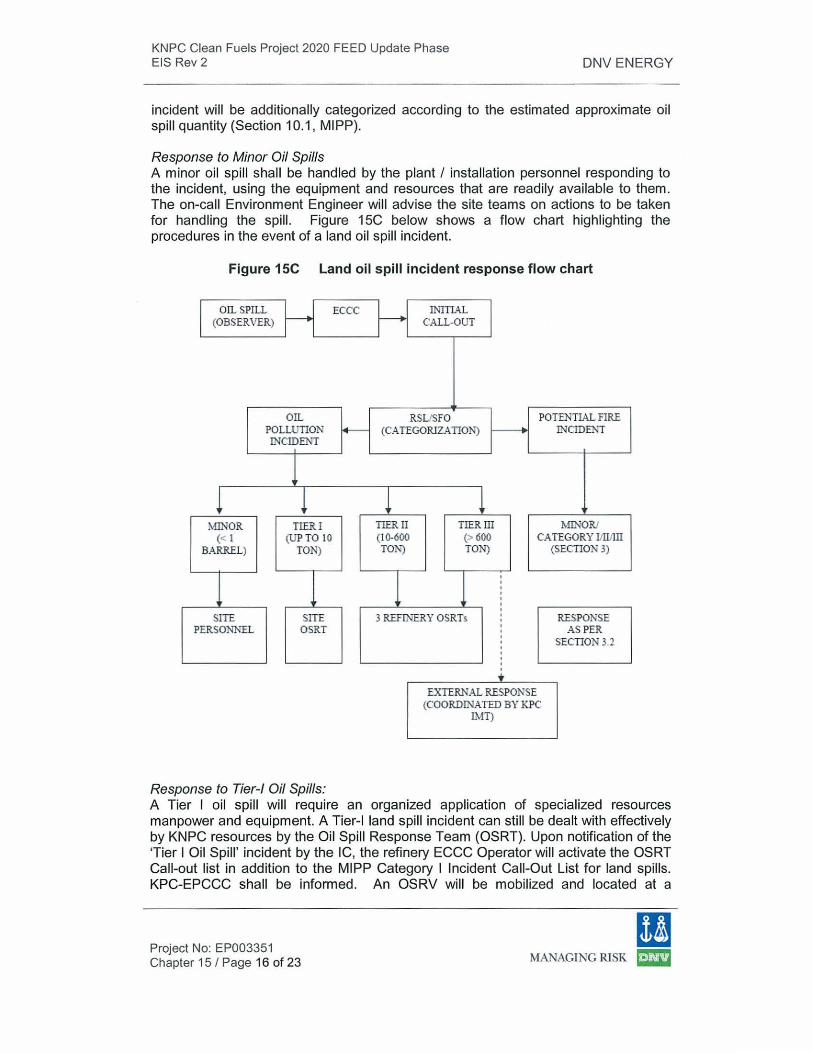
KNPC Clean Fuels Project 2020 FEED Update Phase EIS Rev 2 DNV ENERGY
incident will be additionally categorized according to the estimated approximate oil spill quantity (Section 10.1, MI PP).
Response to Minor Oil Spills A minor oil spill shall be handled by the plant I instal lation personnel respond ing to the incident, using the equipment and resources that are readily available to them. The on-call Environment Engineer will advise the site teams on actions to be taken for handling the spill. Figure 15C below shows a flow chart highlighting the procedures in the event of a land oil spill incident.
Figure 15C Land oil spill incident response flow chart
I OIL SPILL ECCC
(OBSERVER)
OIL POLLUTION f4-INCIDEl\"T
J l l
MINOR TIER I (< 1 (UP TO 10
BARREL) TON)
1 1 SITE SITE
PERSONNEL OSRT
Response to Tier-/ Oil Spills:
INlTIAL CALL-OUT
RSUSFO POTENTIAL FIRE (CA TEGORJZATIOl\') ~ INCIDEl\"T
l TIER !I TIER III MD! OR/ (10-600 (> 600 CATEGORY liiiJIII TON) TON)
1 1 ' ' ' ' ' ' '
3 ~RYOSRTs ' ' ' ' ' ' ' '
EXTERNAL RESPOJ\SE (COORD['IIATED BY KPC
IMT)
(SECTION 3)
RESPOJ\SE AS PER
SECTION 3.2
A Tier I oil spill will require an organized application of specialized resources manpower and equipment. A Tier-1 land spill incident can still be dealt with effectively by KNPC resources by the Oil Spill Response Team (OSRT}. Upon notification of the 'Tier I Oil Spill ' incident by the IC, the refinery ECCC Operator will activate the OSRT Call-out list in addition to the MIPP Category I Incident Call-Out List for land spills. KPC-EPCCC shall be informed. An OSRV will be mobilized and located at a
Project No: EP003351 Chapter 15 I Page 16 of 23
11 MANAGING RISK ~
KNPC Clean Fuels Project 2020 FEED Update Phase EIS Rev 2 DNV ENERGY
strategic location close to the incident site. The OSRT will initiate containment action under the guidance of the I C.
Oil Spill Response Team Leader (identified by a green waistcoat) will coordinate the necessary containment and clean-up operations in coordination with the IC and Environment personnel. For a spill incident expected to last more than 8 hours, he may adopt the additional role of IC provided there are no fire, explosion or chemical I gaseous pollution hazards. A RCC and MCC may be activated, if considered necessary by the IC, especially for Tier I spill incidents expected to last more than 8 hours.
Response to Tier-// Oil Spills: Tier 11 land spill incidents will need resources and support from the other unaffected KNPC refineries. Upon receiving information regarding an incident and its categorization, the ECCC will inform the ECCCs of the unaffected refineries to activate the OSRT call-out lists and dispatch the OSRVs, activate the MIPP Category 11 incident call-out list, and inform KPC-EPCCC.
The OSRVs and OSRT members from unaffected refineries will report to the site OSRT Leader at the Incident Scene and provide support as necessary. Support from other K-companies may be requested through KPC-IMT, if required, for large I or longer duration Tier-11 oil spills.
Response to Tier-Ill Oil Spills: Handling a Tier-Ill incident will require large resources, more organized effort and expertise. KPC-IMT shall coordinate the response from other K-companies and national, regional and international agencies, if required , to optimally coordinate the necessary response operations.
Termination of Incident: The termination of an incident is declared by the IC or ECM on advice from the OSRT Leader. Environment personnel will advise on further clean-up and waste disposal.
15.5.3 Marine Oil Spills
Overview
Adequate oil spill response resources shall be maintained at marine terminals to handle spills on the deck areas. Oil spills in sea shall be handled by KOC Marine & Export Division under a special agreement with KNPC.
Emergency Response
Response to incidents involving the KNPC's marine terminals will be in accordance with Section 11 of the MIPP.
For oil spills limited to deck areas only, the Shift Supervisor will coordinate the appropriate oil spill response, using site personnel and oil spill response material available at the site.
Project No: EP003351 Chapter 15 I Page 17 of 23
(I MANAGING RISK ~
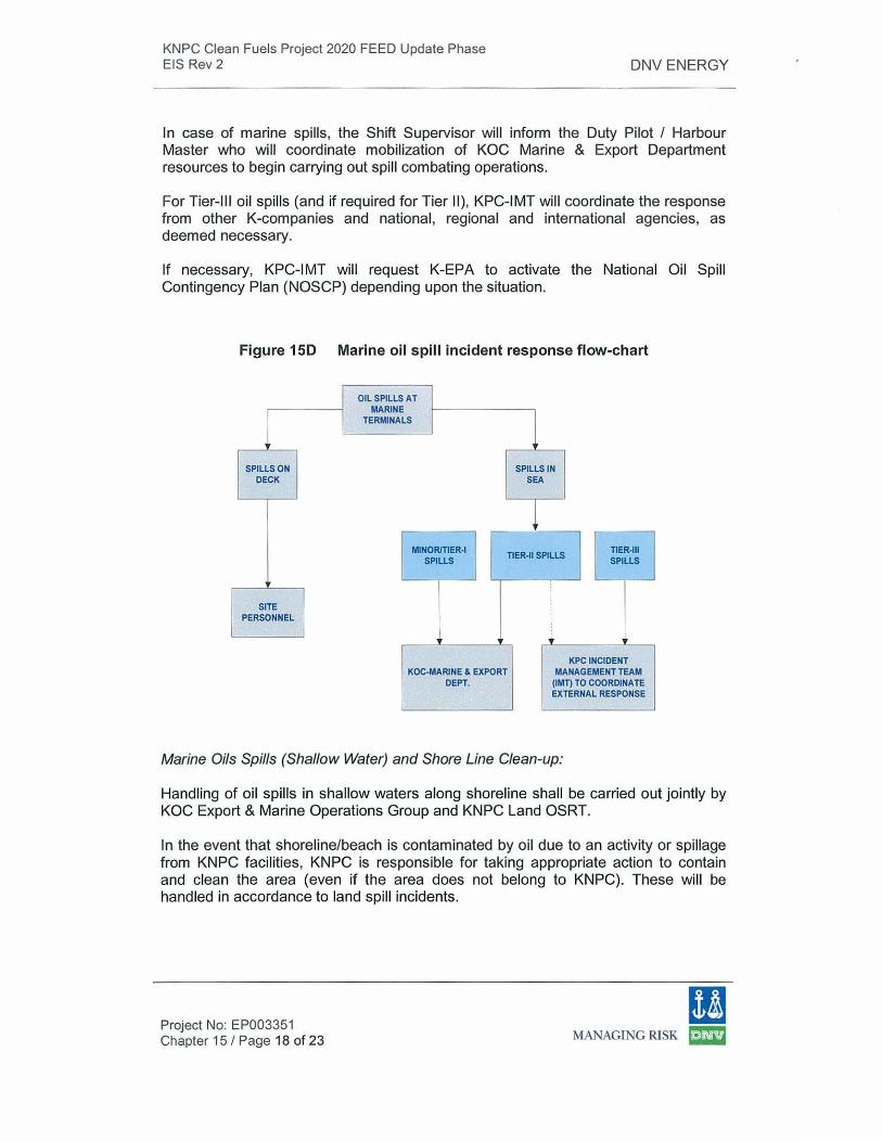
KNPC Clean Fuels Project 2020 FEED Update Phase EIS Rev 2 DNV ENERGY
In case of marine spills, the Shift Supervisor will inform the Duty Pilot I Harbour Master who will coordinate mobilization of KOC Marine & Export Department resources to begin carrying out spill combating operations.
For Tier-Ill oil spills (and if required for Tier 11), KPC-IMT will coordinate the response from other K-companies and national, regional and international agencies, as deemed necessary.
If necessary, KPC-IMT will request K-EPA to activate the National Oil Spill Contingency Plan (NOSCP) depending upon the situation.
Figure 150 Marine oil spill incident response flow-chart
SPILLS ON DECK
SITE PERSONNEL
OIL SPILLS AT MARINE
1 TERMINALS
SPILLS IN SEA
l MINOR/TIER-I
SPILLS TIER-11 SPILLS TIER~II
SPILLS
KOC-MARJNE & EXPORT DEPT.
" KP
MANA CINCIDENT GEMENTTEAM OCOORDINATE (IMT)T
EXTERN AL RESPONSE
Marine Oils Spills (Shallow Water) and Shore Line Clean-up:
Handling of oil spills in shallow waters along shoreline shall be carried out jointly by KOC Export & Marine Operations Group and KNPC Land OSRT.
In the event that shoreline/beach is contaminated by oil due to an activity or spillage from KNPC facilities , KNPC is responsible for taking appropriate action to contain and clean the area (even if the area does not belong to KNPC). These will be handled in accordance to land spill incidents.
Project No: EP003351 Chapter 15 I Page 18 of 23
!I MANAGING RISK ~
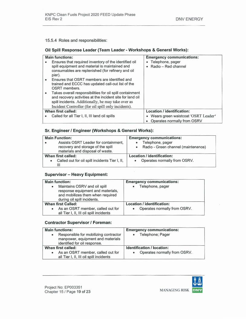
KNPC Clean Fuels Project 2020 FEED Update Phase EIS Rev 2 DNV ENERGY
15.5.4 Roles and responsibilities:
Oil Spill Response Leader (Team Leader- Workshops & General Works):
Main functions: Emergency communications:
• Ensures that required inventory of the identified oi l • Telephone, pager spill equipment and material is maintained and • Radio - Red channel consumables are replenished (for refinery and oil pier).
• Ensures that OSRT members are identified and trained and ECCC has updated call-out list of the OSRT members.
• Takes overall responsibilities for oil spill containment and recovery activities at the incident site for land oil spill incidents. A dditionally , he may take over as Incident Controller (for oil spill only incidents).
When first called: Location I identification:
• Called for all Tier I, 11 , Ill land oil spills • Wears green waistcoat 'OSRT Leader '
• Operates normally from OSRV
Sr. Engineer I Engineer (Workshops & General Works):
Main Function: • Assists OSRT Leader for containment,
recovery and storage of the spill materials and disposal of waste.
When first called:
• Called out for oil spill incidents Tier I, 11 , Il l
Supervisor- Heavy Equipment:
Main function:
• Maintains OSRV and oil spill response equipment and materials, and mobilizes them when required during oil spill incidents.
When first Called:
• As an OSRT member, called out for all Tier I, 11 , Ill oi l spill incidents
Contractor Supervisor I Foreman:
Main functions:
• Responsible for mobilizing contractor manpower, equipment and materials identified for oil response.
When first called: • As an OSRT member, called out for
all Tier I, 11, Ill oil spill incidents
Project No: EP003351 Chapter 15 I Page 19 of 23
Emergency communications:
• Telephone, pager
• Radio- Green channel (maintenance)
Location I identification: • Operates normally from OSRV.
Emergency communications:
• Telephone, pager
Location I identification:
• Operates normally from OSRV.
Emergency communications:
• Telephone; Pager
Identification /location :
• Operates normally from OSRV.
[I MANAGING RISK ~
KNPC Clean Fuels Project 2020 FEED Update Phase EIS Rev 2
15.5.5 KPC-IMT:
DNV ENERGY
KPC IMT comprises of representatives from KPC and its subsidiaries as follows: - IMT chairman: KPC EAMD (Health, Safety & Environment) - IMT coordinator - IMT members representing various K-companies
The Manager, Safety Health & Environment is the IMT Member representing KNPC.
The main function of KPC-IMT is to coordinate with KPC subsidiaries and regional and international agencies, to organise the provision of support in handling major oil spills. KPC-IMT is called by ECCC for oil spill incidents (Tier I, 11 , and Ill).
15.6 MIPP: Security Incidents
MIPP will be activated in the case of any credible security incident/threat as listed in section 15.2.2 of this report.
15.6.1 Notification and Initial Action
Actions in the event of a security incident within a KNPC refinery should be as follows:
1. Person finding any suspicious package/device, observing any security breach or receiving security threat information (through telephone, fax, media or any other means) shall immediately notify the incident to ECCC.
2. ECCC shall immediately invoke the initial call-out. 3. Shift Security Officer will proceed to the incident site and assess the situation
and decide the action plan. 4. ECCC will be informed of the situation and call-out requirements.
Any security breach observed by the security personnel during the normal security checks/patrols shall be informed to the Shift Security Officer who will decide on the action plan and inform ECCC about the incident and the call-out requirements.
15.6.2 Call Outs and Response
In the case of a confirmed security threat/incident, the ECCC will evoke the Security Incident call-out list shall include:
• Chief Security Officer • Team Leader Security • Manager Safety Health & Environment • DMD (affected refinery & SHU) • Manager CCD.
Requirement of calling-in of external agencies shall be decided by the Team Leader Security (and Port Facility Security Officer, if involved). This may include but will not be limited to the State Installation Security Force and/or the National Coast Guard. The decision to activate site MCC and or CMC shall be taken by the DMD and MSH&E depending on the requirement.
Project No: EP003351 Chapter 15 I Page 20 of 23
ll MANAGING RISK ~
KNPC Clean Fuels Project 2020 FEED Update Phase EIS Rev 2 DNV ENERGY
Security threats or incidents affecting KNPC facilities shall be handled in accordance with the 'Response to Threats' and 'Contingency Plan' sections of the KNPC Security Manual.
15.6.3 Emergency Actions in case of a Security Incident
Process Units: The strategy of operating facilities shall be decided based on the assessment of the potential damage of the security threaUincident. The strategy may include:
• Evacuation, all non-essential personnel from the affected area • Reduction of unit capacity and preparation for shutdown. • Total shut down • Total evacuation.
Marine Terminals: In case of a security incident loading shall be suspended immediately. Depending on the situation the PFSO shall initiate the appropriate action as per the guidelines laid out in the IS PS Code.
Security will block the roads around the affected area. All gates shall be strictly monitored. No entry shall be allowed except for the emergency teams. Identity and time of any person leaving the facility shall be recorded. Refinery fire crews, medical and rescue teams will remain on alert (in a safe area) ready to respond when called.
15.7 Evacuation
15.7.1 Overview
There are emergency situations which may require the evacuation of personnel to safer locations, in order to avoid the risk of injury or loss of life, for example:
• Explosion • Release of toxic gas • Release of flammable material having potential to cause fire • Fire • Nuclear, Biological or Chemical (NBC) attack • Bomb threat, sabotage, air raid or other hostile act
A comprehensive and well rehearsed Evacuation Plan is necessary to ensure correct decisions and actions are taken when needed. The MIPP provides guidelines regarding actions to be taken while evacuating personnel in case of an emergency at KNPC site (see MIPP, Section 13). These guidelines will be further supplemented by the SEEPs of the respective sites.
The roles and responsibilities of those involved in the Evacuation Plan are discussed in Section 13.5 of the MIPP. Evacuation procedures are discussed in Section 13.6.
Project No: EP003351 Chapter 15 I Page 21 of 23
[I MANAGING RISK ~
KNPC Clean Fuels Project 2020 FEED Update Phase EIS Rev 2
15.7 .2 Key Parameters of the Site Evacuation Plan
Leaders and Custodians
DNV ENERGY
• Zone leaders (MAA only): Senior person (Team Leader level) appointed as Evacuation Zone Leader for each of the 6 Zones at MAA.
• Asset Custodians: Assigned for all buildings in three refineries. • Group leaders: Each zone I building is divided into groups, led by an
Evacuation Group Leader who ensures safe and orderly evacuation.
Evacuation Maps and Signs
• Overall Site Evacuation maps showing important points shall be displayed. Evacuation Guidelines shall be written on the maps.
• Floor Plans showing location of emergency exits, paths, evacuation routes, local transfer point and evacuation instructions shall be displayed at strategic locations.
• Illuminated Exit Signs shall be provided at each floor.
Gathering Points
• A designated safe area inside/outside site fence shall be identified, as a gathering point for personnel when a site evacuation is announced.
• Alternate gathering points(s), to be used in case one Gathering point can not be used for safety reasons, shall also be identified.
• Gathering area shall be of sufficient size to accommodate personnel. • lt shall be divided into zones and shall have facilities such as drinking water
and first aid. Proper instruction and marking shall be provided for guidance. • Safety Engineers shall act as Gathering Point Coordinator.
Transfer Points • Suitable areas adjacent to individual process units, building or group of
buildings, shall be identified to be utilized as transfer points, for further transportation to main gathering points.
Evacuation Shelters • Certain buildings shall be identified at each site to be used as evacuation
shelters for the essential personnel. • Buildings should be air-tight and provided with hazardous gas filters and air
tight dampers in their air intakes. • Buildings shall be equipped with adequate personal protective equipment,
gas masks, drinking water, first-aid facilities. (Also refer Clause 9.5.9 of MIPP)
Transportation • Shuttle buses and other company provided vehicles, not required to attend
the emergency, shall be used for transporting personnel from transfer points to gathering points.
• Contractors shall make their vehicles available.
Project No: EP003351 Chapter 15 I Page 22 of 23
(I MANAGING RISK !mm
KNPC Clean Fuels Project 2020 FEED Update Phase EIS Rev 2 DNV ENERGY
• Available transport facilities are used to maximum benefit to transport personnel from transfer points to designated gathering points.
15.7.3 Head Count
Accurate head counts require advanced access/exit control systems which cover all employees, contractors and visitors. lt should be possible to get a report indicating the number of personnel present on site at any time.
Existing access control systems at the KNPC Refineries need to be upgraded and extended to gathering points. In the interim, the following practice for head count to be used in process areas:
• For the operations on the assigned field duty in that particular unit, the information from the existing attendance procedure can be used for head count when required
• For the maintenance I contractor work groups present in the unit to execute a job with valid work permit, the work permit executer shall keep a record of personnel assigned for the job.
• All other personnel visiting the area shall inform the operations supervisor while entering I leaving the unit.
Head counts at the gathering points shall be carried out manually by the respective group leaders:
• Group Leaders shall maintain updated lists of personnel working within their point of responsibility.
• Visitors shall always follow their KNPC representative. • Personnel entering the site outside their scheduled hours of work shall
make their presence known to the Shift Security Officer. • On reaching the Gathering Point, all personnel shall report to their
respective group leaders. Group leaders will count personnel and compare with their personnel list and hand over the same to the respective Zone Leader.
• Zone Leaders will compile the head count data for their respective zones and hand over the same to the Gathering Point Coordinator.
• The Gathering Point Coordinator will compile the overall head count data and forward the same to the IC/ECM
15.8 Summary
KNPC's MIPP, the principal features of which have been described above, will be implemented for the CFP. This ensures that KNPC will apply a unified and collective approach to responding to emergencies at all its refineries and other associated facilities (e.g. oil terminals).
Project No: EP003351 Chapter 15 I Page 23 of 23
(I MANAGING RISK ED
KNPC Clean Fuels Project 2020 FEED Update Phase EIS Rev 2 DNV ENERGY
16.0 Decommissioning and Closure Management Plan
16.1 Introduction
Decommissioning is defined as the shutdown of a facility in order to prepare it for complete closure, clean-up and site reinstatement. At the cessation of CFP operation in approximately 30 years time, the CFP will be decommissioned in accordance with statutory requirements in force at the time. In advance of decommissioning, a 'Decommissioning and Closure Management Plan' (DCMP) will be developed by KNPC. The DCMP will be compiled at a time closer to decommissioning to ensure that all the relevant environmental risks are properly managed.
The decommissioning and closure of the CFP site will be a complex process, especially ensuring that the site is rehabilitated to K-EPA's requirements, thus allowing the sites to either be handed back to government control, or be sold for another private sector use.
lt should be noted that the CFP scope of work does not include the retirement or decommissioning of SHU, which is expected to be retired by KNPC when the CFP units are commissioned. The environmental impacts associated with decommissioning of SHU will need to be addressed in a separate decommissioning report by KNPC. SHU units that remain in use during the CFP will be included in the CFP DCMP.
The extent of dismantling, demolition and site clearance will depend upon the future use of the site. There are likely to be three project stages to the CFP decommissioning phase:
• pre-decommissioning consents and contracts: covering the site and structures, plant and processes, municipal and site utilities, fire safety, access and transport, and demolition of buildings etc;
• decommissioning activity obligations: environmental emissions (e.g. effluent discharges, air pollution, noise and dust generation, waste disposal, ground I groundwater contamination etc) , and associated health and safety issues;
• post-decommissioning responsibilities: these are to ensure that everything that needs to be known about a decommissioned site (or plant) is passed on to the new site owners, operators or organizations.
This Chapter provides an overview of the basics involved in establishing a DCMP. lt also discusses the various environmental aspects which will typically be addressed in a DCMP.
Project Number: EP003351 Chapter 16 I Page 1 of 5
[I !vLANAGING RISK ~
KNPC Clean Fuels Project 2020 FEED Update Phase EIS Rev 2
16.2 Decommissioning and Closure Management Plan
16.2.1 Objectives
The specific environmental-related objectives of the DCMP are:
DNV ENERGY
• to meet all pertinent Kuwaiti legal and regulatory requirements, and complete the site clean-up and reinstatement in accordance with applicable K-EPA criteria;
• to protect the public health and safety of local people, and the surrounding environment;
• to ensure that all residual environmental and social impacts are acceptable;
• to ensure that the need for long-term site maintenance is removed as much as possible;
• to ensure that post-reinstatement land-use is in accordance with state (and other key stakeholder) requirements;
• to mitigate and minimise any long-term environmental-related liabilities.
16.2.2 Scope
In accordance with EIA legislative and policy requirements at the time of CFP shutdown (i.e. in approximately 30 years time), KNPC, in consultation with K-EPA, will prepare a conceptual DCMP that addresses the following:
• suitable post-closure land end-uses and decommissioning and closure objectives;
• specific completion criteria for rehabilitated areas, and various closure concept options;
• suitable clean-up and reinstatement prescriptions for all aspects of decommissioning and closure (international best practice requires 3rdparty verification);
• provision of decommissioning and closure monitoring programmes;
• conducting appropriate stakeholder consultation with appropriate parties (e.g. KNPC internally, K-EPA, local communities).
In addition, it should be noted that underground and subsea facilities which go beyond the fence line of the refinery may exist (e.g. pipelines and piers). These will have to be identified accordingly during the decommissioning process. KNPC will need to evaluate whether such facilities can be safely abandoned in place or if they must be removed and disposed of elsewhere.
16.2.3 Roles and responsibilities
Decommissioning and closure management of the CFP, in terms of establishing a conceptual plan, may involve several KNPC internal departments, together with KEPA plus some local stakeholder engagement.
Project Number: EP003351 Chapter 16 I Page 2 of 5
11 MANAGI NG RISK ~
KNPC Clean Fuels Project 2020 FEED Update Phase EIS Rev 2 DNV ENERGY
In terms of the various roles involved in a large decommissioning project such as the CFP, it is likely that the following would be involved:
• KNPC's project management specialists;
• a QA manager;
• Health, Safety, and Environmental (HSE) staff;
• competent decommissioning experts (probably via an external contractor);
• specific technical experts (e.g. waste management etc);
• former CFP operations specialists;
• regulatory authorities.
16.2.4 Environmental Management Liaison group
The DCMP will include some form of decommissioning and environmental management liaison group, to set out the guiding principles to achieve the proposed end-use of the CFP site area. These guiding principles are likely to include the following:
• environmental issues: ensuring that through conducting a full risk assessment and appropriate mapping, characterization and remediation that no pollution, health or safety hazard is posed to areas outside an agreed attenuation zone;
• landform: ensuring that the site is sufficiently and appropriately cleaned up in accordance with its future planned end-use;
• water resources protection: ensuring that there is no diminution of groundwater resources beyond an agreed attenuation zone;
• liability mitigation: ensuring that any long-term residual environmental liabilities pose minimal financial liabilities on the government (e.g. in terms of ongoing site management costs having to be borne by K-EPA or other agencies).
These guiding principles will be applied to the CFP, together with any decommissioning residue areas (e.g. demolition rubble).
16.2.5 Contents
A DCMP is typically structured as follows: • Introduction (including project description, operating history and current
project operations) • Objectives of decommissioning and closure • Decommissioning activities and schedule • Mitigation Measures • Waste Management • Environmental Monitoring • Co-ordination Mechanisms (including roles and responsibilities)
Project Number: EP003351 Chapter 16 I Page 3 of 5
(I ivlANAGING RISK ~
KNPC Clean Fuels Project 2020 FEED Update Phase EIS Rev 2
16.3 Environmental Aspects
DNV ENERGY
This section discusses the key environmenta l aspects that are likely to be associated with decommissioning, clean-up and site reinstatement at the CFP.
16.3.1 Noise and vibration
During decommissioning activities, noise and vibrations may be caused by the operation and transport of heavy moving and excavation equipment. Noise reduction and control strategies such as temporary noise barriers may have to be used.
16.3.2 Air quality
Decommissioning activities will generate em1ss1on of fugitive dust caused by a combination of on-site excavation and movement of earth materials, contact of construction machinery with bare soil and exposure of spoil piles to wind. A secondary source of emissions may include exhaust from diesel engines of earth moving equipment as well as from open burning of solid waste on-site. Techniques to consider for the reduction and control of air emissions from decommissioning activities include dust suppression techniques as well as avoiding open burning of solids on site.
16.3.3 Waste
The shutdown and decontamination of processes will result in the collection of residual wastes in columns, decanters, reaction vessels, storage tanks, sewers etc. The safe treatment and disposal of these wastes will be necessary so that the plant and equipment is left in a fully-decontaminated condition. Non-hazardous waste generated from decommissioning activities will include excess fill materials, scrap wood and metals and small concrete spills. Wherever possible the following waste hierarchy should be observed; reduce, reuse, recycle and dispose.
16.3.4 Soil / groundwater contamination
As a result of both operational and post-operational activities, there is potential for release of petroleum based products such a lubricants and hydraulic fuels during storage, use and transfer of the products. Soil samples may have to be taken in areas of concern to determine the extent of contamination and proper remedial measures implemented depending on the level and location of contamination and the intended post-decommissioning land use.
16.3.5 Miscellaneous
Other potential environmental aspects will include increased traffic from decommissioning activities and impacts to landscape and visual amenities. These should be discussed in detail in the DCMP and should include appropriate mitigation measures.
Project Number: EP003351 Chapter 16 I Page 4 of 5
(I IvlANAGING RlSK [D
KNPC Clean Fuels Project 2020 FEED Update Phase EIS Rev 2
16.4 Conclusions
DNV ENERGY
KNPC will develop a full conceptual DCMP for the CFP when required prior to decommissioning of the CFP in approximately 30 years time. This will ensure that the DCMP is in accordance with contemporary legislation. The DCMP will address all the project stages that CFP decommissioning will go through which are likely to be: pre-decommissioning consents and contracts; decommissioning activity obligations; and post-decommissioning responsibilities. This will send a robust signal that postclosure, the CFP will be optimally decommissioned, prior to handover back to the state or private use.
Specific environmental-related decommissioning and closure objectives associated with the CFP are predicated around meeting all Kuwaiti legal and regulatory requirements (including K-EPA criteria), and mitigating any impacts (environmental, public health, safety, social) within the impact vicinity of the site.
The final goal of the CFP decommissioning will be to ensure that any requirements for post-closure site maintenance are removed as much as possible, and that any long-term environmental-related liabilities are mitigated.
16.5 Recommendations
KNPC will develop a CFP DCMP in accordance with the specifications discussed in this chapter as well as any guidelines or requirements established by the regulatory authorities of Kuwait. The DCMP will be developed at a suitable time near the end of the operational life of the CFP facilities.
The following should be taken into consideration at the time of the DCMP development::
• Dialogue with K-EPA to determine what specific site rehabilitation requirements are likely to be;
• Ensuring that the final DCMP for the CFP is subjected to appropriate stakeholder review; and,
• Replicating or adapting similar DCMP approaches from KNPC's other refineries including a review of lessons learned.
Project Number: EP003351 Chapter 16 I Page 5 of 5
I! MANAGING RISK ~
KNPC Clean Fuels Project 2020 Feed Update Phase EIS Rev 2 DNV ENERGY
17.0 Environment Management System (EMS)
17.1 Introduction
KNPC has developed and implemented a company wide Environmental Management System (EMS) in line with the requirements of the IS014001 :2004 Standard - Apex Manual for Environmental Management System (SHE-ESHU-04-1401 ). Since the CFP is within KNPC refinery boundaries, this EMS will also apply to the CFP, ensuring a structured approach to the management of environmental issues existing at the CFP.
The implementation of the EMS will commence during the initial stages of construction and develop as the CFP project becomes fully operational.
17.2 EMS during Construction
The CFP will have ten EPC contractors: three EPC Contractors at MAA, five EPC Contractors at MAB, one EPC Contractor for SHU and an EPC buildings Contractor. There will be three other major contracts: a high voltage contract and two early works contractors (one in MAA and one in MAB). The buildings and high voltage contractors will have activity in both MAA & MAB.
Each of these EPC contractors will be required to have an approved Environmental Management Plan (EMP) in place, covering their own operations. The EPC contractors will also need to implement the following measures identified in this EIS:
• Waste Management Plan;
• Dust Management Plan;
• Solid Waste Management Procedure;
• Wastewater Management Procedure;
• KNPC HSE Guidelines for Contractors (SHE-TSSA-05-1118).
At the start of the Construction Phase, a Centralized Waste Management Contractor will be identified who will be responsible for coordinating the waste disposal activities of all CFP EPC contractors. Each EPC contractor will develop an Environmental Procedures Manual that details all procedures needed to comply with KNPC environmental procedures as well as K-EPA regulatory requirements.
17.3 EMS: during Operational Phase
The following sections provide an overview of KNPC's approach to implementing an EMS. They have been abstracted from the KNPC Apex Manual for Environmental Management System which describes how KNPC's EMS is currently implemented across refineries and associated facilities.
The purpose of the Apex Manual is to describe KNPC's current EMS and to provide a reference source on implementation, maintenance and continual improvement of the system at KNPC. The Apex Manual also assigns environmental responsibilities, as required by the International Environmental Standard IS0-14001 :2004 and KNPC's Safety, Health & Environment Management System (SHEMS). The EMS
11 Project No EP003351 Chapter 17 I Page 1 of 11 MANAGING RISK ~
KNPC Clean Fuels Project 2020 Feed Update Phase EIS Rev 2 DNV ENERGY
Management Representative (EMR) is responsible for updating the Apex Manual in accordance with the SHEMS documentation system.
17.3.1 EMS Requirements
The following sub-sections provide some guidance on the principal KNPC EMS requirements which will be implemented at the CFP.
17 .3.1.1 General Requirements:
KNPC has established an EMS in line with ISO 14001:2004 and is committed to maintaining and improving it on a continual basis. Specific requirements within the EMS are described in subsequent sections of the Apex Manual.
17 .3.1.2 Environmental (SH&E) Policy
KNPC's Environmental (SH&E) Policy has been defined by the Chairman and Managing Director (C&MD) to provide a framework for establishing KNPC's overall environmental objectives and targets. The policy covers all key aspects of KNPC's operations and associated services, is displayed at various strategic locations and is also available on KNPC's intranet, and externally to the public on KNPC's website. The policy also acts as a supplement to tender documents to make KNPC's contractors and suppliers aware of it. Contractors are also advised to ensure that their personnel working for KNPC are aware of KNPC's SH&E Policy.
17 .3.1.3 Planning
Environmental aspects
KNPC has established a procedure for identifying the environmental aspects of its activities, products and services that are under its control or can be influenced. Accordingly, aspects are identified and evaluated for significance by respective departments I divisions. A list of significant aspects along with the identified controls is forwarded to the EMR for review and to be recorded. New aspects are also identified prior to execution of new projects or modification I expansion of existing projects as per KNPC's Procedure on Environmental Impact Assessment (SHEESHU-03-1407).
Legal and other requirements
Legal and other requirements applicable to the environmental aspects of KNPC's activities, products and related services are identified through considering applicable national and international environmental regulations, and other environmental requirements mentioned in the standards I practices being followed by KNPC. These requirements are listed in KNPC's 'Environmental Legislative Register'.
Regular direct contact is established with K-EPA for updates on any amendments or new regulations on the environment. New information on environmental regulations is also received from KPC. All such amended laws I regulations are studied by KNPC's Environment Division with the relevant regulations being updated in KNPC's Environmental Legislative Register.
[! Project No EP003351 Chapter 17 I Page 2 of 11 MANAGING RISK ~
KNPC Clean Fuels Project 2020 Feed Update Phase EIS Rev 2 DNV ENERGY
The Register is reviewed and updated, if required, once a year or as necessary according to amendments I inclusions to existing applicable regulations. The Register is distributed to all concerned for reference and compliance and can be accessed on the KNPC intranet. Each EPC contractor will have their own Aspect Register.
Objectives, targets and programmes
KNPC has developed environmental objectives based on its significant environmental aspects, SH&E Policy, legal and other requirements, technology options, operational requirements, business requirements, financial resources and views of interested parties. To achieve the above objectives within a specified time frame, environmental targets are set. The targets are applicable either across KNPC as a whole, or to individual departments I divisions. To achieve the objectives and targets, environmental management programmes are established, with responsibilities and action plans at the company, department I division and group levels as appropriate. These programmes are reviewed to keep track of progress towards meeting objectives and targets. Progress on these various programmes is discussed in Management Reviews. Each EPC Contractor will have their own specific environmental objectives, targets and programmes.
17.3.1.4 Implementation and Operation
The roles, responsibilities and authorities of relevant personnel for effective environmental management at KNPC are outlined below:
The C&MD is responsible for:
• appointing the EMS EMR;
• framing the SH&E Policy;
• ensuring the establishment, implementation, maintenance and improvement of the EMS by providing adequate resources.
The EMR is responsible and authorized to:
• establish, implement, maintain and improve the EMS across KNPC;
• appraise top management on EMS performance and action plans for improvement;
• ensure that internal audits are carried out as per the schedule;
• ensure sufficient resources are made available for implementation and maintenance of the EMS.
• communicate with K-EPA and other government bodies on environmental I legal issues.
Project Managers I DMDs I Manager - LM are responsible for the following activities relating to their sites:
• implementing and maintaining the EMS at their sites;
• carrying out all activities in compliance with legal requirements;
11 Project No EP003351 Chapter 17 I Page 3 of 11 MANAGING RISK ~
KNPC Clean Fuels Project 2020 Feed Update Phase EIS Rev 2 DNV ENERGY
• ensuring sufficient resources are made available for implementation and maintenance of the EMS.
Department Managers are responsible for the following relating to their department:
• identifying the training needs for all employees with respect to the EMS, and ensuring appropriate training is implemented;
• identifying aspects and ensuring that significant aspects are appropriately controlled;
• ensuring that all environmental incidents are reported;
• ensuring that resources are available to meet the objectives and targets;
• ensuring that a Document Control System is followed for all EMS documents;
• ensuring that non-conformances are resolved to ensure compliance.
Team Leaders are responsible for the following, relating to their divisions:
• identifying training needs for all employees with respect to the EMS, and ensuring appropriate training is implemented;
• aspects are identified and the Aspects Register is maintained and up to date;
• effective controls are in place for significant aspects;
• programmes to achieve objectives and targets are prepared and implemented;
• objectives and targets are met;
• a Document Control System is followed;
• all key characteristics are identified and monitored;
• all environmental incidents are reported;
• environmental records are maintained;
• all non-conformances are resolved, to ensure compliance.
Senior Engineer I Senior Chemist I Section Head I Lead Engineer I Lead Chemist I Engineer I Chemists are responsible for the following, relating to their sections:
• identifying training needs for all employees with respect to the EMS and facilitating I arranging their training as appropriate;
• identification and updating the Aspects Register;
• identifying effective controls for significant aspects;
• identifying all key characteristics I parameters associated with the significant aspects;
• monitoring all the key characteristics I parameters;
• preparing programmes for objectives and targets;
• meeting objectives and targets;
• following the required Document Control System for EMS documents;
• reporting all environmental incidents, and maintaining environmental records;
• resolving any non-conformances, to ensure compliance (through taking appropriate corrective and preventive actions for any non-conformances).
(I Project No EP003351 Chapter 17 I Page 4 of 11 MANAGING RISK ~
KNPC Clean Fuels Project 2020 Feed Update Phase EIS Rev 2 DNV ENERGY
Supervisors, in their respective sections, are responsible for the following:
• assisting in the identification of training needs for subordinates with respect to the EMS, and facilitating I arranging their training;
• adhering to the work instructions I procedures;
• keeping abreast with significant aspects associated with their activities;
• being aware of controls on the significant aspects;
• being aware of Emergency Handling Procedures;
• reporting environmental incidents immediately;
• monitoring key characteristics I parameters.
Contractor Managers I Engineers, in addition to their assigned responsibilities, are responsible for the following :
• identification of training needs for subordinates with respect to the EMS requirements, and facilitating I arranging their training;
• communication of KNPC's SH&E Policy and respective significant aspects (plus associated controls) to their staff;
• communication of Emergency Handling Procedures to their staff;
• reporting environmental incidents.
For the EMS Site Team , the head of the team will report to respective Site-DMD (for three refineries) or manager (for LM&PD). The Team will assist the site in effective implementation and maintenance of the EMS complying with IS014001 :2004 requirements. In particular, the team shall ensure that:
• The latest HSE Policy is displayed at all strategic locations of the site.
• The Aspects Register is updated in the latest format, by all concerned, as stated in the Apex Manual.
• The latest copy of the Aspects Register is communicated to the EMS-MR office.
• New Objectives and Targets proposed by the site are SMART.
• The Objectives and Targets are tracked and forwarded to the EMS-MR office on a six-monthly basis or whenever requested.
• All employees I contractors are well aware of the KNPC-EMS and that records of training are maintained with the concerned division I department.
• The current KNPC document control procedure is followed by all departments I divisions of the site.
• Hard copies (green folder) of the EMS manuals I procedures are discarded
• All EMS records such as calibration records, monitoring reports, programs to manage objectives and targets, training records, non-conformities and close out reports, waste disposal records and mock drill reports are available to the concerned department/division.
• Key characteristics of activities which can have significant environmental impact are identified and monitored and records are kept by all concerned departments I divisions.
ll Project No EP003351 Chapter 17 I Page 5 of 11 MANAGING RlSK ~
KNPC Clean Fuels Project 2020 Feed Update Phase EIS Rev 2 DNV ENERGY
• Root cause analysis is done for all non-conformances and other audit findings and that a compliance plan is submitted to the EMS-MR Office in the prescribed format.
• The status of the previous audit findings is updated and that the status report is submitted to the EMR office on a monthly basis.
• Settlement of decisions is taken in the Management Review by the concerned department I division.
Specific Responsibilities:
Oil Spill Response Team (OSRT) Leaders and Team Leaders (in addition to their responsibi lities stated above under 'Team Leaders') are responsible for the following:
• maintaining Oil Spill Response equipment in good working cond ition;
• establishing OSRC near the incident scene;
• coordinating with other refineries and external agencies, if required , for management of the incident;
• coordinating with OSRT members to equip OSRC with all required emergency handling equipment;
• categorizing any spillage;
• coord inating clean-up activities;
• briefing top management about the incident;
• coord inating with process for storage and reuse of spilled material;
• coord inating with KNPC's Environment Division for disposal of any wastes.
Team Leader Environment (Refineries) , in addition to the responsibility stated above under 'Team Leaders', is responsible for ensuring the following:
• that K-EPA and other legal requirements are complied with;
• that new projects I modifications are scrutinized for the requirement of carrying out EIA studies;
• that regular environmental monitoring is carried out;
• that environmental monitoring reports (monthly, quarterly, annual) are generated and issued to all concerned at the relevant levels;
• direct communication with K-EPA on compliance status;
• that KNPC's Legislative Register is updated;
• that environmental aspects of all sites are identified and evaluated for significance;
• that necessary EMS documents are developed and issued for compliance;
• that EMPs are in place for all environmental objectives, and for generating status reports on EMPs.
• that EMS procedures are complied with;
• that effective Oil Spill Response procedures are available;
• that external and internal environmental complaints are properly handled;
• that waste is managed in an environment-friendly manner;
(I Project No EP003351 Chapter 17 I Page 6 of 11 MANAGING RISK ~
KNPC Clean Fuels Project 2020 Feed Update Phase EIS Rev 2 DNV ENERGY
• that regular environmental inspections are carried out, and advice issued;
• that environmental incidents are investigated and recommendations issued;
• that tracking recommendations are issued after incident investigation and environment inspection;
• that regular environment awareness training, and environment campaigns are organized;
• that Planned Environmental Releases are recorded;
• that data desired by shareholders and other external parties are reported I supplied.
Refinery Shift Leader (RSL) and Divisional Heads are responsible for:
• logging and reporting environmental incidents;
• assuming the role of IC for effective management of incidents;
• initial categorization of the incident, and calling-out appropriate personnel for the effective management of the incident;
• logging and coordinating internal as well as external environmental complaints;
• locating the source of the complaint within KNPC (if applicable);
• identifying the incident 'owner';
• activating the investigation team .
• communicating with management about the incident.
Competence, Training and Awareness:
Successful implementation and operation of the EMS depends on all the capabilities of those individuals performing the tasks assigned as required. lt is to ensure that all personnel performing tasks which could lead to significant environmental impacts are competent on the basis of appropriate education, training and/or experience. Training needs for such personnel are identified and required training is imparted to them. This training is not only imparted to staff but also to the persons working for or on behalf of KNPC - i.e. contractors and sub-contractors, via their engineers and managers who in turn will train their staff as appropriate. Records of such training should be maintained and kept by the contractor.
Communication:
Environmental communications, internal (within KNPC) as well as external (with external interested parties) are addressed in KNPC's Environmental Communication Procedure. Besides communicating its significant aspects to associated contractors, KNPC is also committed to communicating with local communities.
Documentation:
Various environmenta l procedures I documents have been developed and must be complied with for effective implementation of the EMS across KNPC's operations. Related documents include:
(I Project No EP003351 Chapter 17 I Page 7 of 11 MANAGING RISK ~
KNPC Clean Fuels Project 2020 Feed Update Phase EIS Rev 2 DNV ENERGY
• IS0-14001:2004 standard;
• KNPC's SH&E Policy, and environmental objectives and targets
• Apex Manual for EMS (ISO 14001) (SHE-ESHU-04-1401 ).
• KNPC's Environmental Legislative Register (SHE-ESHU-04-1402)
• Environmental Communication Procedure (SHE-ESHU-03-1403)
• Procedure on Air Pollution Monitoring & Control (SHE-EMAB-01-1404)
• Procedure on Monitoring of Wastewater Treatment & Disposal (SHE-ESHU-02-1405)
• Procedure for Solid Waste Management (SHE-ESHU-03-1406)
• Procedure on EIA (SHE-ESHU-03-1407)
• Aspects Registers of respective departments
• KNPC's Major Incident Procedure Plan (MIPP)
• SH&E Training Procedure (SHE-TSTR-05-1501)
• Controlled Documents System Manual (SMS-EI06-04-0001)
In addition to the above, there are various department-specific procedures, such as operations manuals I procedures I standing instructions I maintenance manuals I standard testing methods etc. , which are controlled by the respective departments.
Control of Documents:
Necessary controls are exercised to ensure all EMS documents are kept updated and obsolete documents are promptly removed. All documents are reviewed periodically and the changes I modification incorporated are approved and issued by authorized persons as per the 'Controlled Document System Manual'. The author is responsible to keep copies of the manual updated at all relevant locations.
Operational Control:
All operations and activities which are associated with significant environmental aspects are identified by the respective departments I divisions I areas and any necessary operational control procedures are documented.
These Operation Control Procedures include department-specific procedures such as operations manuals I procedures I standing instructions I maintenance manuals I procedures etc. In addition to these, the following environmental procedures are also termed as Operation Control Procedures:
• Procedure on Air Pollution Monitoring & Control (SHE-EMAB-01-1404)
• Procedure on Monitoring of Wastewater Treatment & Disposal (SHE-ESHU-02-1405)
• Solid Waste Management Procedure (SHE-ESHU-03-1406)
I! Project No EP003351 Chapter 17 I Page 8 of 11 MANAGING RISK tD
KNPC Clean Fuels Project 2020 Feed Update Phase EIS Rev 2 DNV ENERGY
Emergency Preparedness and Response:
Major emergencies are identified and addressed by KNPC's Major Incident Procedure Plan (MIPP) - see Chapter 15 of this EIS. MIPP assigns the responsibilities of key personnel in handling the major emergencies such as fire, toxic gas release, oil spill on land or sea etc. The potential for unit-specific environmental emergencies are identified in respective Aspects Registers and addressed via plantspecific Emergency Handling Procedures. To test the efficiency of procedures and the preparation of emergency response, mock drills are periodically conducted involving all the role players.
Checking:
Monitoring and measurement: Key characteristics I parameters covered by legal and other requirements are monitored by the Laboratory, Environment Division and the Lab Service Contractor. Monitoring results are published in Environment Performance reports issued by the Environment Division. Other key characteristics I parameters that have a significant impact on the environment are monitored by respective departments (or divisions). Lists of instruments used for such monitoring and their calibration reporting (if applicable}, along with the monitoring reports, are kept by respective departments. Equipment used for monitoring environmental parameters is calibrated as per appropriate calibration schedules, with records maintained by the respective departments.
Evaluation of compliance: Legal requirements are listed in KNPC's 'Environmental Legislative Register'. Compliance with various other conditions I stipulations, as prescribed, are also addressed therein, plus other requirements. The Register must be reviewed and updated, if required, once a year or as necessary due to amendment I inclusion in existing applicable regulations.
Non-conformances, corrective and preventive actions: Non-conformances can arise from several areas including system non-conformance, operational non-conformance, complaints etc. Non-conformances are dealt with according to the 'Procedure for Handling Non-conformances and Corrective Actions & Preventive Actions'. Corrective and preventive actions taken to eliminate the causes of actual and potential non-conformances must be appropriate to the magnitude of the problem, and be commensurate with the environmental impact(s) encountered.
Control of records: Relevant records that demonstrate effective operation of the EMS must be maintained, legible, identifiable and traceable to the activity, product or service involved, and be kept for a minimum period of three years. However, the retention time of some records may be more than three years based on statutory or other requirements. In such cases, the retention period is decided by the respective department. Adequate back-up of these records is ensured by the respective department to avoid the same being lost due to any unforeseen circumstances. Once the retention period for any record is over, such records can be destroyed by the respective department.
m Project No EP003351 Chapter 17 I Page 9 of 11 MANAGING RISK £D
KNPC Clean Fuels Project 2020 Feed Update Phase EIS Rev 2 DNV ENERGY
Internal audits:
An internal Environment Management System Audit shall be carried out at least once in a year for each site. Internal audits must be carried out in order to determine whether the EMS conforms to planned arrangements for environmental management including the requirements of ISO 14001:2004, and that it has been properly implemented and maintained. Also, to provide information on the results of audits to management whereby the EMR will plan a series of internal audits on the basis of the 'environmental importance' of the area I services I activity and on the findings of previous audits (as per the 'Procedure for Internal Audit'). EMR may reduce the audit frequency for departments/divisions which are not having a critical role in EMS.
17.3.1.4 Management Review:
Environmental Management Review meetings must be carried out at least twice each year in SH&E Executive Committee meetings to ensure the EMS's suitability, adequacy, and effectiveness. Points to be considered in the Management Review include (as applicable):
• results of internal audits and evaluation of compliance with legal requirements and with other requirements to which KNPC subscribes;
• communications with external interested parties, including complaints;
• the environmental performance of KNPC, and the extent to which objectives and targets have been met;
• the status of all corrective and preventive actions;
• follow-up actions from previous Management Reviews;
• changing circumstances, including developments in legal and other requirements related to KNPC's environmental aspects;
• a review of the SH&E Policy, and its adequacy in relation to changing conditions and information;
• a review of Accidents I Incidents and Emergencies;
. • a schedule I plan for the next internal audits;
• any recommendation for improvement;
• any other specific points relating to EMS.
Decisions made in Management Reviews are recorded in the form of Minutes of Meetings (MoM). These decisions include possible changes to KNPC's SH&E policy, objectives, targets and other elements of EMS, consistent with the commitment to continual improvement. All action items of the MoM are followed up by the EMR to ensure compliance.
17.4 Monitoring Compliance
In order to optimise KNPC's response to complying with changing environmental regulations (and its corporate requirements), it is noted that KNPC has already implemented a fully-automated enterprise-level information management system -the 100% browser-based Essential Suite TM EHS and Crisis Management system
ll Project No EP003351 Chapter 17 I Page 10 of 11 MANAGING RISK tD
KNPC Clean Fuels Project 2020 Feed Update Phase EIS Rev 2 DNV ENERGY
from ESS - at MAA, MAB and SHU. This system will be extended to the CFP facilities.
Essential Suite TM facilitates the use of EHS and crisis management data in support of regulatory reporting and performance monitoring, as well as demonstrating how KNPC is exercising its corporate social responsibility. KNPC is also using Essential Suite TM in the CFP's FEED design phase. Essential Suite TM is also a core component of KNPC's project action plan to address its long-term sustainability. Key Essential Suite rM elements applied at KNPC's refineries include:
• Essential Air™ - an emissions tracking system which shows how changes in everyday operations can impact air permits, by calculating and reporting air emissions and comparing them against permit limits for all emissions sources;
• Essential Water™ - helps to achieve, maintain and prove compliance with Kuwait's National Pollutant Discharge Elimination System (NPDES), by tracking regulatory requirements or internal guidelines, calculating pollutant loadings at each discharge point and comparing results to specified limits, so helping to ensure compliance;
• Essential Waste TM - helps to characterize waste streams, monitor their flow, track waste containers, generate waste manifests and generate reports to ensure compliance;
• Essential Chemical Inventory™ - helps track chemical inventory information for use in satisfying inventory-related regulatory requirements, via a central data repository, which enables amounts I locations of materials to be tracked.
• Industrial Hygiene Module rM - provides the tools needed to characterize workplace conditions, collect, document and analyze exposure monitoring results, communicate monitoring results to employees and management, identify opportunities to further control exposures, and assure compliance.
17.5 Conclusions
KNPC's company-wide EMS, in line with the requirements of IS014001 :2004, will be implemented for the CFP. As a tried and tested system, it will provide the same structured approach for the optimum management of environmental issues at the CFP. The principal mechanism by which this will be done is through KNPC's Apex Manual which sets out how the EMS is currently implemented across KNPC's existing refineries and associated facilities. In addition, ESS's Essential Suite™ EHS and Crisis Management system, shows how compliance monitoring and reporting at the CFP will be optimised.
17.6 Recommendations
KNPC intends to incorporate the CFP into the scope of the EMS. lt is recommended that the CFP be included in the first possible EMS internal and external audit to ensure that the EMS is being successfully applied to the CFP.
(I Project No EP003351 Chapter 17 I Page 11 of 11 MANAGING RISK ~
KNPC Clean Fuels Project 2020 FEED Update Phase EIS Rev 2
18.0 Recommendations
18.1 Introduction
DNV ENERGY
The CFP design will incorporate all the appropriate best environmental engineering practices (such as BACT) and environmental mitigation measures necessary to meet (at a minimum) all relevant K-EPA regulatory criteria. The CFP has been designed to mitigate all its potentially significant environmental impacts.
In addition, DNV has made a number of recommendations throughout this EIS report, which are reported in detail in the relevant chapters, in order to further mitigate any potential environmental impacts caused by the CFP. These key additional recommendations are summarised here.
18.2 Noise
The noise impact assessment evaluated the potential community impact due to the noise emissions from the activities associated with CFP. Predictive computational modelling was used to quantitatively estimate the sound pressure level (SPL) at various discrete receptors located near the ground level. From this assessment, the following recommendations are made:
• Construction activities shall not be carried out during the night time except under very exceptional situations. Otherwise, night time community noise levels may significantly breach the relevant K-EPA standards at residential locations close to the site fence lines.
• In order to fully comply with K-EPA community noise standards, additional noise attenuation using acoustic enclosures should be considered for significant noise emitting sources located close to the fence lines, particularly for CFP works near the eastern part of the CFP at MAB refinery.
• The process units where additional attenuation should be considered are U-123, U-125, U-129, U-146, U-149 and U-156. All these units are located in MAB CFP Block and they are close to the residential receptors N11 , N13, N14 and N16 on the east side of the site. The additional attenuation required would be about 5 dB(A).
• Noise monitoring will be necessary during both construction and operation to ensure no significant impact upon receptors.
18.3 Air Quality During Construction
Potential issues associated with dust released during the CFP construction phase have been assessed. DNV considers that provided the following recommendations are adopted, impacts upon air quality during construction can be managed satisfactorily.
Project No. EP003351 Chapter 18 I Page 1 of 5
11 1vlANAGING RlSK tD
KNPC Clean Fuels Project 2020 FEED Update Phase EIS Rev 2 DNV ENERGY
• A rigorous Dust Management Plan is provided by the EPC contractors and is put into action.
• The Dust Management Plan should include some early commitment to provide temporary construction roads as soon as practicable to minimise dust releases.
• The EPC contractors ensure that appropriate dust mitigation measures are applied, both by themselves and their sub-contractors.
• The EPC contractors conduct ongoing monitoring of dust across the CFP site throughout the construction phase.
• An experienced independent environmental professional visits the site during construction at least twice a week to ensure that these measures (and all other environmental management measures recommended in this EIS report) are being applied by EPC contractors.
18.4 Air Quality During Operations
Overall , particularly during "normal" CFP operation, there will be improvements in air quality at the vast majority of air monitoring locations that currently do not meet KEPA air criteria. This is mainly due to the fact that pollutant emissions from sources that are to be decommissioned far exceed the emissions associated with new CFP sources.
DNV additionally recommends the following:
• KNPC implement design changes during the EPC phase in order to reduce the relief loads to the flare systems that have the highest potential impact on sensitive receptors outside the refinery boundaries (Units 146, 167 and 62; note that Unit 62 is associated with the Total Power Failure case).
• More detailed air dispersion modelling of the emergency flare scenarios should then be conducted during the detailed design I EPC stages of the project, to verify compliance with applicable criteria.
• Currently, the MIPP provides procedures for responding to gas release incidents. These should be expanded to include details for major emergency flaring events, and appropriate actions defined (e.g. warning residents).
• The CFP clearly improves air quality in the study area on a day-to-day basis, although exceedences for some parameters are still observed. lt is recommended that scope for additional air quality improvements at the existing refineries be examined under KNPC's ongoing commitment to continuously improve environmental performance.
• lt is important that a strict Leak Detection and Repair (LDAR) programme is implemented and enforced onsite to control VOC emissions. The new CFP facilities will be incorporated in the existing refineries LDAR programme.
Project No. EP003351 Chapter 18 I Page 2 of 5
(I MANAGlNG RlSK ~
KNPC Clean Fuels Project 2020 FEED Update Phase EIS Rev 2 DNV ENERGY
• The Environmental Management System for the Clean Fuels Project should include a continuous performance improvement process for evaluating and maintaining the efficacy of emissions control equipment, and energy efficiency. The CFP facilities will be incorporated in the existing refineries' EMS.
18.5 Waste
The CFP will generate a variety of solid wastes that are both hazardous and nonhazardous. The impacts of the wastes generated by the CFP were considered for both the construction and operational phases. The waste management practices that KNPC plans to implement for the CFP are more than adequate and no additional recommendations have been made by DNV.
lt is important that all the control measures discussed in this report are fully implemented, including the generation of a Waste Management Plan (WMP), which complies with KNPC's Procedure for Solid Waste Management (SHE-ESHU-03-1406).
18.6 Chemical Hazards Management
The CFP will store and/or handle a variety of potentially hazardous materials, including finished product, raw material and catalysts, many of which are similar to those currently used at the three existing refineries. The hazardous materials will be potentially toxic, corrosive, flammable etc. The hazardous materials management practices that KNPC plans to implement for the CFP are more than adequate and thus no additional recommendations have been made by DNV.
lt is important that all the control measures discussed in this report are fully implemented, and that the management systems comply with K-EPA requirements for the handling, storage and disposal of hazardous materials.
18.7 Wastewater
DNV has assessed the environmental impacts from the collection, treatment and reuse of process and sanitary wastewater effluents generated by the CFP. lt is concluded that the planned new CFP wastewater collection and treatment facilities are state of the art, constitute best practice and will be designed, built and operated to meet K-EPA environmental criteria.
In order to augment the robust approach to addressing and mitigating environmental impacts during the CFP construction and subsequent operations, DNV made the following additional recommendations with regards to wastewater treatment:
• lt will be important to ensure that, during construction, the wastewater, storm water and sanitary wastewater collection and treatment facilities are made available at the earliest stage possible; it is recommended that each EPC contractor makes this an early priority.
• lt will be important to review and audit the CFP wastewater discharge monitoring results (during both construction and operation); it is
Project No. EP003351 Chapter 18 I Page 3 of 5
11 MANAGING RJSK ~
KNPC Clean Fuels Project 2020 FEED Update Phase EIS Rev 2 DNV ENERGY
recommended that monitoring results are audited by an independent party on a regular basis.
18.8 Preliminary Traffic Impact Assessment (TIA)
A preliminary assessment was conducted that highlighted that there could be traffic impacts during CFP construction. lt is recommended that a detailed TIA be conducted to further study local traffic patterns with the objective of determining the current status of local roadways relative to their design carrying capacity. This information should be used as the basis for development of a comprehensive CFP Traffic Management Plan to ensure impacts are managed acceptably via detailed traffic control measures.
18.9 Miscellaneous
The following miscellaneous issues were also considered in this EIS:
• Landscape and visual impacts • Socioeconomic issues • Contaminated land and groundwater
The following recommendations came from these studies:
• Use good practices to decrease water demand and protect water supply.
• Screening of CFP construction and operation from sensitive receptors by hording or earth bunds, particularly at the refinery fence adjacent to the beach houses southeast of MAB. This may also provide additional benefit to reduce wind-blown dust and noise during construction and operation.
• Site lighting is recommended to be designed and located to keep off-site glare to a minimum and minimise the impact on visual amenity at night, having due regard to operational, emergency, security and safety requirements.
• Where possible, tone and colour treatment of plant structures should ensure that the development fits in with surroundings and will blend elements into the horizon and sky line when viewed from a distance.
• An independent environmental advisor should be present on site while soil excavations are taking place to ensure that the soil is excavated and disposed of in the correct manner, and to help identify any other areas of contamination.
• lt is recommended that regular checks for fugitive emissions to ground/groundwater from CFP refinery plant and tanks are included as part of the EMS, and that systematic groundwater monitoring is conducted around the CFP facilities and in the vicinity of the tank farms, and analysed against agreed criteria. Additionally, soil and groundwater identified as contaminated in the KISR report and overlapping with the
Project No. EP003351 Chapter 18 I Page 4 of 5
11 JVIANAGING RISK ~
KNPC Clean Fuels Project 2020 FEED Update Phase EIS Rev 2 DNV ENERGY
CFP location will require remediation prior to the start of CFP construction.
• The EPC contractor should develop a plan to handle the potential negative social impacts from such a large influx of construction workers.
18.10 Emergency Response Plan
The KNPC Major Incident Procedure Plan (MIPP) will be applied to the CFP. MIPP is one of KNPC's Emergency Plans that provides a procedural framework for responding to emergency incidents such as fire or a flammable/toxic release. Currently the MIPP provides procedures for responding to gas release incidents. These should be expanded to include details for major emergency flaring events, and appropriate actions defined (e.g. warning residents).
18.11 Decommissioning and Closure
KNPC will develop a full conceptual Decommissioning and Closure Management Plan (DCMP) for the CFP, which will involve consultation with K-EPA, as closure planning progresses. KNPC will develop the DCMP in accordance with the guidelines and requirements established by the regulatory authorities of Kuwait. The DCMP will be developed at a suitable time near the end of the operational life of the CFP facilities.
18.12 Environmental Management System
KNPC has developed and implemented a company wide Environmental Management System (EMS) in line with the requirements of the IS014001 :2004 Standard - Apex Manual for Environmental Management System (SHE-ESHU-04-1401 ). Since the CFP is within KNPC refinery boundaries, this EMS will also apply to the CFP, ensuring a structured approach to the management of environmental issues existing at the CFP.
The implementation of the EMS will commence during the initial stages of construction and develop as the CFP project becomes fully operational. lt is recommended that the CFP be included in the first possible EMS internal and external audit to ensure that the EMS is being successfully applied to the CFP project.
Project No. EP003351 Chapter 18 I Page 5 of 5
11 l\tlANAGlNG RJSK ~
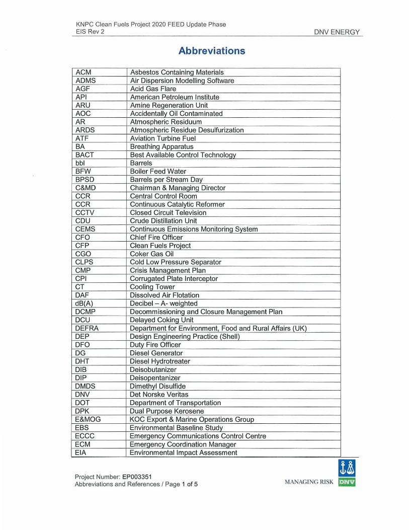
KNPC Clean Fuels Project 2020 FEED Update Phase EIS Rev 2
Abbreviations
ACM Asbestos Containing Materials ADMS Air Dispersion Modelling Software AGF Acid Gas Flare API American Petroleum Institute ARU Amine Regeneration Unit AOC Accidentally Oil Contaminated AR Atmospheric Residuum ARDS Atmospheric Residue Desulfurization ATF Aviation Turbine Fuel BA Breathing Apparatus BACT Best Available Control Technology bbl Barrels BFW Boiler Feed Water BPSD Barrels per Stream Day C&MD Chairman & Managing Director CCR Central Control Room CCR Continuous Catalytic Reformer CCTV Closed Circuit Television CDU Crude Distillation Unit CEMS Continuous Emissions Monitoring System CFO Chief Fire Officer CFP Clean Fuels Project CGO Coker Gas Oil CLPS Cold Low Pressure Separator CMP Crisis Management Plan CPI Corrugated Plate Interceptor CT Cooling Tower OAF Dissolved Air Flotation dB( A) Decibel - A- weighted DCMP Decommissioning and Closure Management Plan DCU Delayed Coking Unit
DNV ENERGY
DEFRA Department for Environment, Food and Rural Affairs (UK) DEP Design Engineering Practice (Shell) DFO Duty Fire Officer DG Diesel Generator DHT Diesel Hydrotreater DIB Deisobutanizer DIP Deisopentanizer DMDS Dimethyl Disulfide DNV Det Norske Veritas DOT Department of Transportation DPK Dual Purpose Kerosene E&MOG KOC Export & Marine Operations Group EBS Environmental Baseline Study ECCC Emergency Communications Control Centre ECM Emergency Coordination Manager El A Environmental Impact Assessment
Project Number: EP003351 Abbreviations and References I Page 1 of 5
11 MANAGING RISK ~
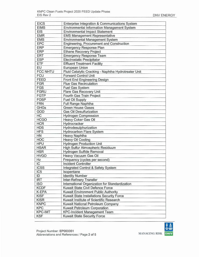
KNPC Clean Fuels Project 2020 FEED Update Phase EIS Rev 2
EICS Enterprise Integration & Communications System ElMS Environmental Information Management System EIS Environmental Impact Statement EMR EMS Management Representative EMS Environmental Management System EPC Engineering, Procurement and Construction ERP Emergency Response Plan ERP Ethane Recovery Project ERT Emergency Response Team ESP Electrostatic Precipitator ETF Effluent Treatment Facility EU European Union
DNV ENERGY
FCC NHTU Fluid Catalytic Cracking - Naphtha Hydrotreater Unit FCU Forward Control Unit FEED Front End Engineering Design FGR Flue Gas Recirculation FGS Fuel Gas System FGRU Flare Gas Recovery Unit FGTP Fourth Gas Train Project FOSP Fuel Oil Supply FRN Full Range Naphtha GHGs Green House Gases GOD Gas Oil Desulfurization HC Hydrogen Compression HCGO Heavy Coker Gas Oil HCR Hydrocracker HDS Hydrodesulphurization HFS Hydrocarbon Flare System HN Heavy Naphtha HOC Heavy Oil Cooling HPU Hydrogen Production Unit HSAR High Sulfur Atmospheric Residuum HSR Hydrogen Sulfide Removal HVGO Heavy Vacuum Gas Oil Hz Frequency (cycles per second) IC Incident Controller ICSS Integrated Control & Safety System ICS lsopentane ID Identity Number IRT Inter-Refinery Transfer ISO International Organization for Standardization KCDF Kuwait State Civil Defence Force K-EPA Kuwait Environment Public Authority KISF Kuwait State Installations Security Force KISR Kuwait Institute of Scientific Research KNPC Kuwait National Petroleum Company KPC Kuwait Petroleum Corporation KPC-IMT KPC-Incident Management Team KSF Kuwait State Security Force
Project Number: EP003351 Abbreviations and References I Page 2 of 5
11 MAI~AGING RISK ~
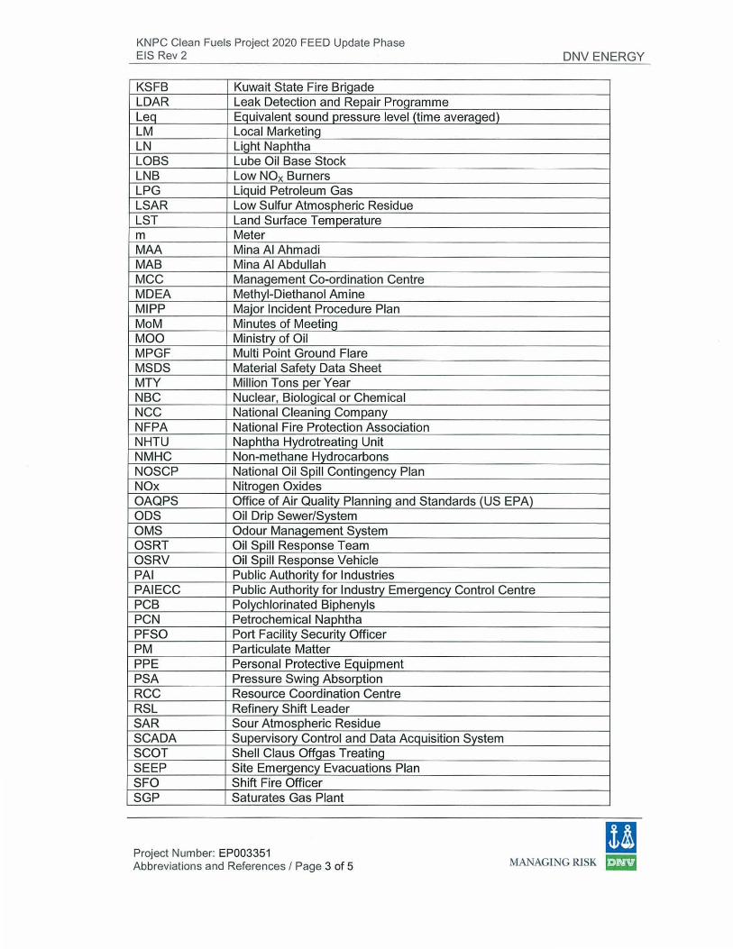
KNPC Clean Fuels Project 2020 FEED Update Phase EIS Rev 2
KSFB Kuwait State Fire Brigade LDAR Leak Detection and Repair Programme Leq Equivalent sound pressure level (time averaged) LM Local Marketing LN Light Naphtha LOBS Lube Oil Base Stock LNB Low NOx Burners LPG Liquid Petroleum Gas LSAR Low Sulfur Atmospheric Residue LST Land Surface Temperature m Meter MAA Mina AI Ahmadi MAB Mina AI Abdullah MCC Management Co-ordination Centre MDEA Methyi-Diethanol Amine M IPP Major Incident Procedure Plan MoM Minutes of Meeting MOO Ministry of Oi l MPGF Multi Point Ground Flare MSDS Material Safety Data Sheet MTY Million Tons per Year NBC Nuclear, Biological or Chemical NCC National Cleaning Company NFPA National Fire Protection Association NHTU Naphtha Hydrotreating Unit NMHC Non-methane Hydrocarbons NOSCP National Oil Spill Contingency Plan NOx Nitrogen Oxides OAQPS Office of Air Quality Planning and Standards (US EPA) ODS Oil Drip Sewer/System OMS Odour Management System OSRT Oil Spill Response Team OSRV Oil Spill Response Vehicle PAl Public Authority for Industries PAIECC Public Authority for Industry Emergency Control Centre PCB Polychlorinated Biphenyls PCN Petrochemical Naphtha PFSO Port Facility Security Officer PM Particulate Matter PPE Personal Protective Equipment PSA Pressure Swing Absorption RCC Resource Coordination Centre RSL Refinery Shift Leader SAR Sour Atmospheric Residue SCADA Supervisory Control and Data Acquisition System SCOT Shell Claus Offgas Treating SEEP Site Emergency Evacuations Plan SFO Shift Fire Officer SGP Saturates Gas Plant
DNV ENERGY
(I Project Number: EP003351 Abbreviations and References I Page 3 of 5 MANAGING RlSK ~
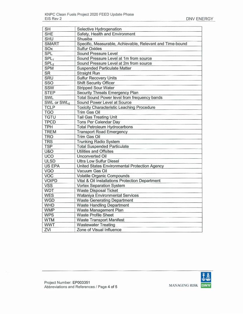
KNPC Clean Fuels Project 2020 FEED Update Phase EIS Rev 2
SH Selective Hydrogenation SHE Safety, Health and Environment SHU Shuaiba
DNV ENERGY
SMART Specific, Measurable, Achievable, Relevant and Time-bound SOx Sulfur Oxides SPL Sound Pressure Level SPL1 Sound Pressure Level at 1 m from source SPLz Sound Pressure Level at 2m from source SPM Suspended Particulate Matter SR Straight Run SRU Sulfur Recovery Units sso Shift Security Officer ssw Stripped Sour Water STEP Security Threats Emergency Plan SWL Total Sound Power level from frequency bands SWL orSWL0 Sound Power Level at Source TCLP Toxicity Characteristic Leaching Procedure TGO Trim Gas Oil TGTU Tail Gas Treating Unit TPCD Tons Per Calendar Day TPH Total Petroleum Hydrocarbons TREM Transport Road Emergency TRO Trim Gas Oil TRS Trunking Radio System TSP Total Suspended Particulate U&O Utilities and Offsites uco Unconverted Oil ULSD Ultra Low Sulfur Diesel US EPA United States Environmental Protection Agency VGO Vacuum Gas Oil voc Volatile Organic Compounds VOIPD Vital & Oil Installations Protection Department vss Vortex Separation System WDT Waste Disposal Ticket WES Wataniya Environmental Services WGD Waste Generating Department WHD Waste Handling Department WMP Waste Management Plan WPS Waste Profile Sheet WTM Waste Transport Manifest WWT Wastewater Treating ZVI Zone of Visual Influence
Project Number: EP003351 Abbreviations and References I Page 4 of 5
(I MANAGING RISK ~
KNPC Clean Fuels Project 2020 FEED Update Phase EIS Rev 2 DNV ENERGY
References 1. BS IS015664:2001. Acoustics - Noise Design Procedures for Open Plant 2. Fluor, 2007. Environmental Impact Assessment (EIA) Initial Report for the Clean
Fuels Project (CFP) 2020. Rev. B. 3. Fluor, 2009. Project Specification for Environmental Design Philosophy.
P6000CFP.000.1 0.1 0.006, Rev. G. 4. Fluor, 2007. Groundwater Monitoring Well Construction. Rev. A. 5. KNPC Apex manual for Environmental Management System
(IS014001 :2004), 2009. SHE-ESHU-04-1401. Rev. 07. 6. KNPC Asbestos Abatement Programme, 2004. SHE-TSOH-04-1321.Rev.O 7. KNPC Chemical Hazard Management Procedure, 2004. SHE-TSOH-04-1358.
Rev Draft 8. KNPC Exposure Assessment Programme, 2004. SHE-TSOH-01-1318. Rev. 0. 9. KNPC Exposure Standards, 2004. SHE-TSOH-04-4301 . RevO. 10. KNPC Industrial Hygiene Programme, 2004. SHE-TSOH-04-1311. Re. vO. 11. KNPC Legislative Register, 2009. SHE-ESHU-04-1402. Rev. 09. 12. KNPC Procedure on Air Pollution Monitoring and Control, 2006. SHE
EMAB-01-1404. Rev. 02. 13. KNPC Procedure for Solid Waste Management, February 2008, SHE-ESHU-
03-1406, Rev. 04 14. KNPC Procedure on Environmental Impact Assessment Study, October
2008, SHE-ESHU-03-1407, Rev. 03 15. KNPC Procedure on Monitoring of Wastewater Treatment and Disposal,
June 2007. SHE-ESHU-02-1405. Rev. 03. 16. KNPC Safe Practices on Confined Space Entry, 2006. SHE-STSA-04-SP-
2007. Rev. 01. 17. KNPC SHE Policy, 2008. Rev. 03. 18. KNPC Waste Profile Sheet 19. KNPC, March 2009. Major Incident Procedure Plan (MIPP). Rev. 07. 20. KPC Corporate HSE Standard Chemical Handling, 2004. Document 19. 21. KPC Corporate HSE Standard Environmental Impact Assessment
Guideline, 2004. Document 20. 22. KPC Corporate HSE Standard Management of Air Emissions, 2004.
Document 16. 23. KPC Corporate HSE Standard Management of Energy and Resources, 2004.
Document 18. 24. KPC Corporate HSE Standard Management of Environmental Regulations,
Permits, 2004. Document 12. 25. KPC Corporate HSE Standard Management of Soil and Ground protection,
2004. Document 15. 26. KPC Corporate HSE Standard Management of Waste Minimisation and
Disposal, 2004. Document 13. 27. KPC Corporate HSE Standard Management of Wastewater Discharge, 2004.
Document 14. 28. Kuwait EPA Regulations, 2001. Decision No. 201 0/2001 Pertaining to the
Executive By-Law of the Law of Environment Public Authority. Issue No. 533, Year 47.
29. KNPC SHE Guidelines for Contractors, August 2008. SHE-TSSA-05-1118 Rev. 5.
30. Shell, 2004. Noise Control (Amendments/Supplements to IS015664).
Project Number: EP003351 Abbreviations and References I Page 5 of 5
(I MANAGING RISK ~
KNPC Clean Fuels Project 2020- FEED Update Phase EIS Rev 2 DNV ENERGY
Appendix I - Refinery Tanks under hydrocarbon service
EP003351 Page 1 of 1
11 MANAGING RlSK ~
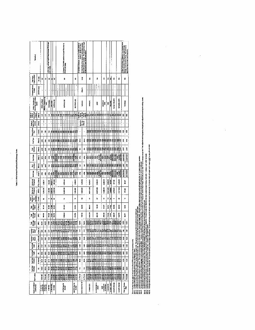
I :1!11
fjii I* I' ' I' ' ' ' i, 1, , ,
llll· i
lj ltl !
! I i Ill! •! i lt !till
I H ! ! lW ' .
. I . . ... I
I ! ! ! i ' ' ' ' ' 1- ' ,
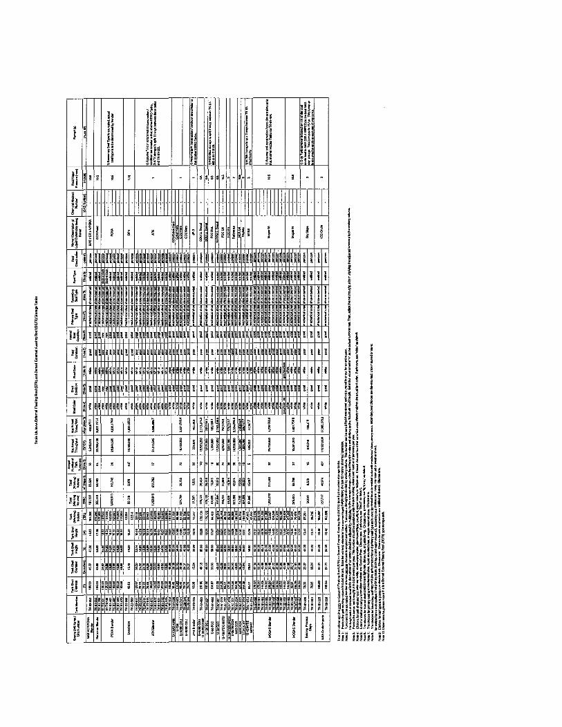
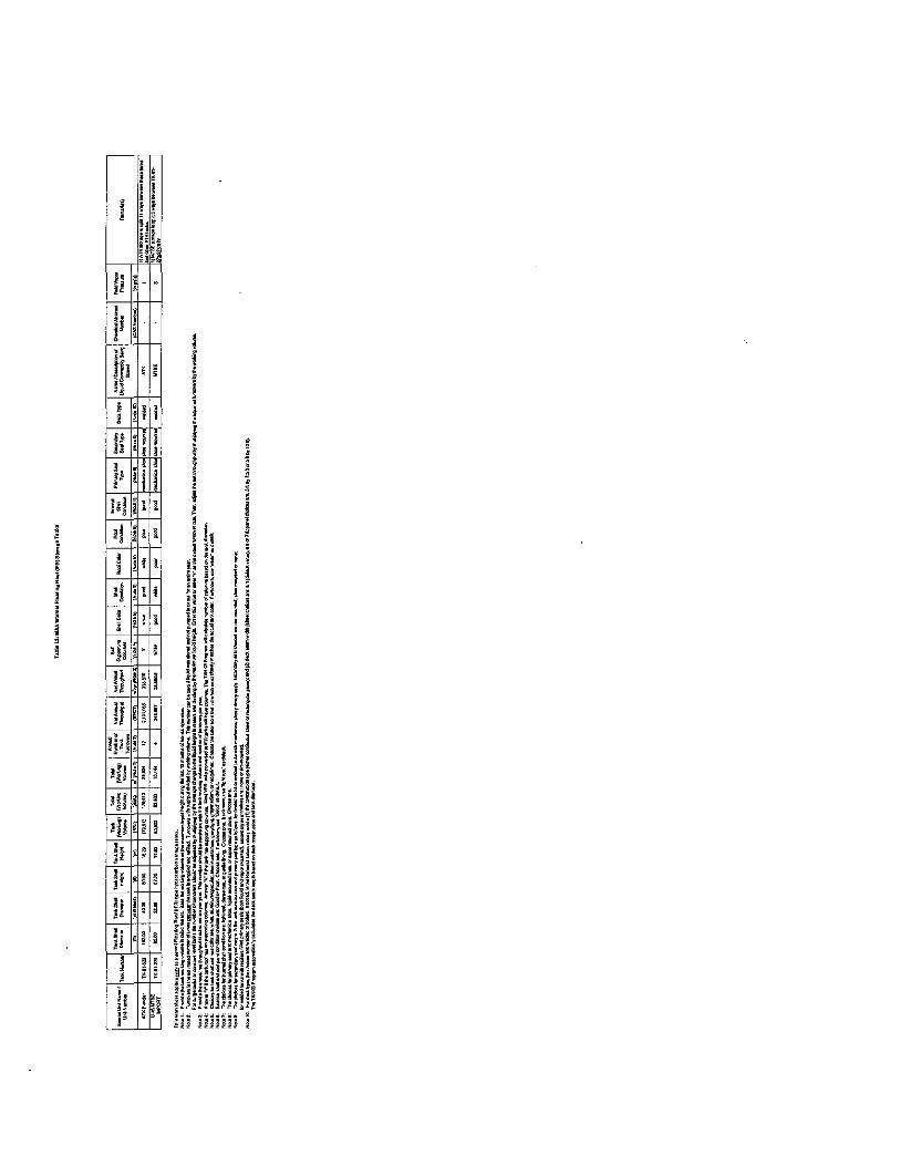
~
I ! f ! ; ' i
i j I
l l i ; ii i -: i f~ ~~ !lh
u ~- " .. I j! i •f
!il ~ ~ h •• • ill l ,, ~ , ll ;J! l, ll I· l-j •• ;l l
lj I ! l
! I l I I
l! ; I l
! I 5 i 1
•I!' • l
p I' ·i i !
!J ~ ! ' . Jjl !;-. ,,, .. , j ~ ~
>if •• ~ ~
* .. ~ ~ !• ;f ~ ~
l• ~I 2 ~ a !I !l ~ ! l
!l ;l ' ' ; . l ! ! ! ; ' h l •. ji . '! ~ ~
• l ' ' ' • i ' 'J !, 1! ,. •• l' ·i '., ili m· pi ;!ij •li Hti Ja~l ~h~ !!' •i d ! . ... H ~~if1 ,., l! jlfiJ! tj. 1' i•ll·l ~<jl r.
h i!il; il!!lji HIU11 'fllill ~ ~~ lH ;l•jl•! !iit!~J j!l,lli HiHH

lHJ
!
ii!~i
' !Ls"' ~/!!
f ll~h i "'Je
' i r···
• fj I•
! ~ .. ll~
~~~i~
• g;;;r'
i ... I l ••• J'!• •hf
' i '
>j
• • g i' •
! • i I '
! I •
.. i
p ' ~ • l
I ··! i . fBj
t!J :~ i • H
!H •'
h i , g '.
.! ,, n
! i 'I
!
" ! '
il •• i n 1 ,, -~ '
•· l ~ <
f ! !
' ' ; • -· i 1 !~ ' fl h•
§ < i -· l
h !
H , . ·l i ••
• • '
i' ,l l'
hi ••
i ' 'J
'" l·
. " '
~i~ i • '
§
i ~
--b • : ~ ~~ i ~ ! i ~i~
.. I . ~:ii ~
,, ! • ;f~
£! il
•
:! ,_
! I•
•t • ~i
I • l{
'. I !
H il
,, •
·" ""
l • .f ~ ~j!
' i
• l ' • !·
H j
~ .. • l
o{ i:. ! ''l ! ~ .. ! li
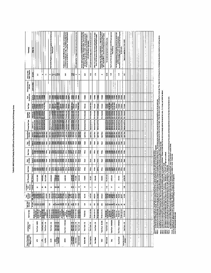
it
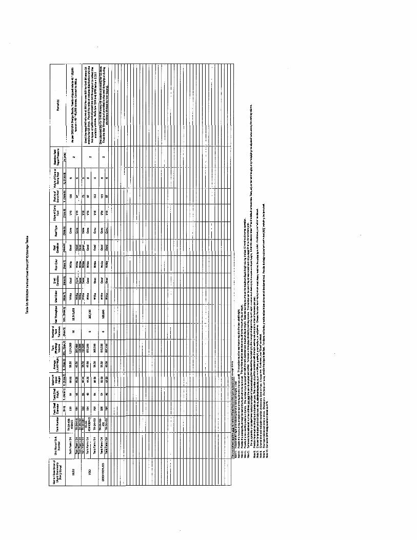
I
N N
[I- 1-1-1-
l l l . ' l l ; ~
I i l ' i I l l ' • ' ' • '
'''"'" i t i
!ii!>H•l l <
)if' lfi~_u_~--t;~fttH-tfmmf++fi+ft+-f-W-1-W-UliillUlJi·· ii H Hi f
!I~ ~ 11 1111 11111111111111 111111111111111111
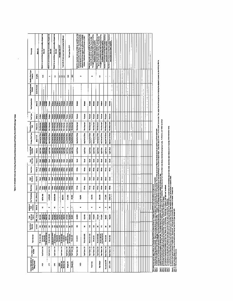
I: I~ [i[i[i[ ~.1'1~~ 'I;:;: !lilil i i I i I i I I I I ~~
fi--t!+-~ ~~ I+ ~~"-+ll+ ~~-++-~-J-~ t-~ tt1 nitttttf,ffittttHtlttttMHHmH ill[ i . I • ' I • " • • • I • I • I


