Embed Size (px)
Citation preview
OFFSHORE STANDARD
The electronic p
DNV-OS-C104
Structural Design of Self-Elevating Units (LRFD Method)
APRIL 2012
DET NORSKE VERITAS AS
df version of this document found through http://www.dnv.com is the officially binding version
FOREWORD
DET NORSKE VERITAS (DNV) is an autonomous and independent foundation with the objectives of safeguarding life,property and the environment, at sea and onshore. DNV undertakes classification, certification, and other verification andconsultancy services relating to quality of ships, offshore units and installations, and onshore industries worldwide, andcarries out research in relation to these functions.
DNV service documents consist of among others the following types of documents:— Service Specifications. Procedural requirements.— Standards. Technical requirements.— Recommended Practices. Guidance.
The Standards and Recommended Practices are offered within the following areas:A) Qualification, Quality and Safety MethodologyB) Materials TechnologyC) StructuresD) SystemsE) Special FacilitiesF) Pipelines and RisersG) Asset OperationH) Marine OperationsJ) Cleaner EnergyO) Subsea Systems
© Det Norske Veritas AS April 2012
Any comments may be sent by e-mail to [email protected]
This service document has been prepared based on available knowledge, technology and/or information at the time of issuance of this document, and is believed to reflect the best ofcontemporary technology. The use of this document by others than DNV is at the user's sole risk. DNV does not accept any liability or responsibility for loss or damages resulting fromany use of this document.
Offshore Standard DNV-OS-C104, April 2012Changes – Page 3
CHANGES
GeneralThis document supersedes DNV-OS-C104, October 2008.
Text affected by the main changes in this edition is highlighted in red colour. However, if the changes involvea whole chapter, section or sub-section, normally only the title will be in red colour.
Main changes: General— Update the reference to latest recommended practice, i.e. to DNV-RP-C104 instead of Classification Note
31.5.— Some minor updates and clarification in text.
• Sec.2— C302 Material Grade NV690 E is sufficient for thick rack plates.
• Sec.3— Dynamic Amplification Factor omitted when DAF ≤ 1.10 Guidance note B403. — Wind profile Guidance note to C202.— Wind unrestricted service Guidance note to C302.
• Sec.4— Clarify vertical position of heavy equipment during transit Guidance note D700. — Guide for simplified PΔ effect Guidance note E201.
• Sec.5— Spudcan design loads B204.
• Sec.8— Load factor = 1.0 for overturning stability check Guidance note C100.
DET NORSKE VERITAS AS
Offshore Standard DNV-OS-C104, April 2012 Contents – Page 4
CONTENTS
Sec. 1 Introduction ........................................................................................................................................ 7
A. General ........................................................................................................................................................................... 7A 100 Introduction........................................................................................................................................................... 7A 200 Objectives ............................................................................................................................................................. 7A 300 Scope and application ........................................................................................................................................... 7A 400 Classification ........................................................................................................................................................ 7
B. References ...................................................................................................................................................................... 8B 100 Offshore standards ................................................................................................................................................ 8B 200 Recommended Practices, Classification Notes and other references ................................................................... 8
C. Definitions ...................................................................................................................................................................... 8C 100 Verbal forms ......................................................................................................................................................... 8C 200 Terms .................................................................................................................................................................... 8
D. Abbreviations and Symbols.......................................................................................................................................... 9D 100 Abbreviations........................................................................................................................................................ 9D 200 Symbols ................................................................................................................................................................ 9
Sec. 2 Structural Categorisation, Material Selection and Inspection Principles................................................................................................................. 11
A. General ......................................................................................................................................................................... 11A 100 Scope................................................................................................................................................................... 11
B. Structural Categorisation........................................................................................................................................... 11B 100 Structural categorisation ..................................................................................................................................... 11
C. Material Selection ....................................................................................................................................................... 12C 100 General................................................................................................................................................................ 12C 200 Design and service temperatures ........................................................................................................................ 12C 300 Selection of structural steel................................................................................................................................. 12
D. Inspection Categories.................................................................................................................................................. 13D 100 General................................................................................................................................................................ 13
Sec. 3 Design Principles .............................................................................................................................. 14
A. Introduction................................................................................................................................................................. 14A 100 General................................................................................................................................................................ 14A 200 Overall design ..................................................................................................................................................... 14A 300 Details design ..................................................................................................................................................... 14
B. Design Conditions ....................................................................................................................................................... 14B 100 Basic conditions .................................................................................................................................................. 14B 200 Transit ................................................................................................................................................................. 14B 300 Installation and retrieval ..................................................................................................................................... 15B 400 Operation and survival........................................................................................................................................ 16
C. Environmental Conditions ......................................................................................................................................... 16C 100 General................................................................................................................................................................ 16C 200 Wind.................................................................................................................................................................... 17C 300 Waves.................................................................................................................................................................. 17C 400 Current ................................................................................................................................................................ 17C 500 Temperature ........................................................................................................................................................ 18C 600 Snow and ice ....................................................................................................................................................... 18
D. Method of Analysis...................................................................................................................................................... 18D 100 General................................................................................................................................................................ 18D 200 Global structural models ..................................................................................................................................... 19D 300 Local structural models....................................................................................................................................... 19D 400 Fatigue analysis................................................................................................................................................... 20
Sec. 4 Design Loads..................................................................................................................................... 21
A. Introduction................................................................................................................................................................. 21A 100 General................................................................................................................................................................ 21
B. Permanent Loads ........................................................................................................................................................ 21B 100 General................................................................................................................................................................ 21
DET NORSKE VERITAS AS

Offshore Standard DNV-OS-C104, April 2012 Contents – Page 5
C. Variable Functional Loads......................................................................................................................................... 21C 100 General................................................................................................................................................................ 21C 200 Lifeboat platforms............................................................................................................................................... 21C 300 Tank loads........................................................................................................................................................... 21
D. Environmental Loads ................................................................................................................................................. 22D 100 General................................................................................................................................................................ 22D 200 Wind loads .......................................................................................................................................................... 22D 300 Waves.................................................................................................................................................................. 23D 400 Current ................................................................................................................................................................ 23D 500 Wave and current loads....................................................................................................................................... 24D 600 Sea pressures during transit ................................................................................................................................ 24D 700 Heavy components during transit ....................................................................................................................... 25
E. Deformation Loads ..................................................................................................................................................... 25E 100 General................................................................................................................................................................ 25E 200 Displacement dependent loads............................................................................................................................ 25
F. Accidental Loads ......................................................................................................................................................... 26F 100 General................................................................................................................................................................ 26
G. Fatigue Loads .............................................................................................................................................................. 26G 100 General................................................................................................................................................................ 26
H. Combination of Loads ................................................................................................................................................ 26H 100 General................................................................................................................................................................ 26
Sec. 5 Ultimate Limit States (ULS)............................................................................................................ 27
A. General ......................................................................................................................................................................... 27A 100 General................................................................................................................................................................ 27A 200 Global capacity ................................................................................................................................................... 27
B. Structural Capacity..................................................................................................................................................... 27B 100 General................................................................................................................................................................ 27B 200 Footing strength .................................................................................................................................................. 28B 300 Leg strength ........................................................................................................................................................ 28B 400 Jackhouse support strength ................................................................................................................................. 29B 500 Hull strength ....................................................................................................................................................... 29
C. Scantlings and Weld Connections ............................................................................................................................. 29C 100 General................................................................................................................................................................ 29
Sec. 6 Fatigue Limit States (FLS) .............................................................................................................. 30
A. General ......................................................................................................................................................................... 30A 100 General................................................................................................................................................................ 30
B. Fatigue Analysis .......................................................................................................................................................... 30B 100 General................................................................................................................................................................ 30B 200 World-wide operation ......................................................................................................................................... 30B 300 Restricted operation ............................................................................................................................................ 30B 400 Simplified fatigue analysis.................................................................................................................................. 30B 500 Stochastic fatigue analysis .................................................................................................................................. 31
Sec. 7 Accidental Limit States (ALS) ........................................................................................................ 32
A. General ......................................................................................................................................................................... 32A 100 General................................................................................................................................................................ 32
B. Collisions ...................................................................................................................................................................... 32B 100 General................................................................................................................................................................ 32
C. Dropped Objects ......................................................................................................................................................... 33C 100 General................................................................................................................................................................ 33
D. Fires .............................................................................................................................................................................. 33D 100 General................................................................................................................................................................ 33
E. Explosions .................................................................................................................................................................... 33E 100 General................................................................................................................................................................ 33
F. Unintended Flooding................................................................................................................................................... 33F 100 General................................................................................................................................................................ 33
DET NORSKE VERITAS AS
Offshore Standard DNV-OS-C104, April 2012 Contents – Page 6
Sec. 8 Special Considerations..................................................................................................................... 35
A. General ......................................................................................................................................................................... 35A 100 General................................................................................................................................................................ 35
B. Pre-load Capacity........................................................................................................................................................ 35B 100 General................................................................................................................................................................ 35
C. Overturning Stability.................................................................................................................................................. 36C 100 General................................................................................................................................................................ 36
D. Air Gap......................................................................................................................................................................... 36D 100 General................................................................................................................................................................ 36
App. A Permanently Installed Self-Elevating Units ................................................................................... 38
A. Introduction................................................................................................................................................................. 38A 100 General................................................................................................................................................................ 38
B. Fatigue.......................................................................................................................................................................... 38B 100 General................................................................................................................................................................ 38
C. Inspection and Maintenance ...................................................................................................................................... 38C 100 Facilities for survey ............................................................................................................................................ 38
DET NORSKE VERITAS AS
Offshore Standard DNV-OS-C104, April 2012 Sec.1 – Page 7
SECTION 1INTRODUCTION
A. General
A 100 Introduction
101 This standard provides principles, technical requirements and guidance for the design and constructionof self-elevating units. 102 This standard is based on the load and resistance factor design (LRFD). LRFD is defined in DNV-OS-C101.
103 Self-elevating units may alternatively be designed according to working stress design principles, whichis defined in DNV-OS-C201.
104 The standard has been written for general world-wide application. Coastal State regulations may includerequirements in excess of the provisions of this standard depending on size, type, location and intended serviceof the offshore unit/installation.
A 200 Objectives
201 The objectives of this standard are to:
— provide an internationally acceptable standard of safety for self-elevating units by defining minimumrequirements for the structural design, materials and construction
— serve as a technical reference document in contractual matters between purchaser and manufacturer— serve as a guideline for designers, purchasers, contractors and regulators.— specify procedures and requirements for units and installations subject to DNV verification and
classification services.
A 300 Scope and application
301 This standard applies to all types of self-elevating units constructed in steel.
302 All marine operations shall, as far as practicable, be based upon well-proven principles, techniques,systems and equipment and shall be undertaken by qualified, competent personnel possessing relevantexperiences.
303 A self-elevating unit is designed to function in a number of modes, e.g. transit, operational and survival.Design criteria for the different modes shall define and include relevant consideration of the following items:
— intact condition, structural strength— damaged condition, structural strength— fatigue strength— accidental damage— air gap— overturning stability— watertight integrity and hydrostatic stability.
Limiting design criteria when going from one mode to another shall be established and clearly documented.
Watertight integrity and hydrostatic stability shall comply with requirements given in DNV-OS-C301.
304 For novel designs, or unproven applications of designs where limited or no direct experience exists,relevant analyses and model testing, shall be performed which clearly demonstrate that an acceptable level ofsafety is obtained.
305 Requirements concerning riser systems are not considered in this standard.
306 Structural design covering marine operation sequences is not covered in this standard and shall beundertaken in accordance with the requirements stated in Rules for Planning and Execution of MarineOperations.
A 400 Classification
401 Principles, procedures and applicable class notations for classification of offshore units are given in theDNV Offshore Service Specifications listed in Table A1. These refer to the present standard for structuralrequirements related to self-elevating units.
Table A1 DNV Offshore Service SpecificationsReference TitleDNV-OSS-101 Rules for Classification of Drilling and Support UnitsDNV-OSS-102 Rules for Classification of Floating Production, Storage and Loading Units
DET NORSKE VERITAS AS
Offshore Standard DNV-OS-C104, April 2012 Sec.1 – Page 8
402 Documentation for classification shall be in accordance with the DNV Nauticus Production System fordocumentation requirements (NPS DocReq).403 Technical requirements given in DNV-OS-C101 Sec.8, related to Serviceability Limit States, are notmandatory as part of classification.404 Technical requirements given in DNV-OS-C101 related to design for earthquakes are not mandatory aspart of classification.
B. References
B 100 Offshore standards101 The standards listed in Table B1 include provisions, which through reference in this text constituteprovisions for this standard. 102 Other recognised standards may be used provided it is demonstrated that these meet or exceed therequirements of the standards referenced in Table B1.
B 200 Recommended Practices, Classification Notes and other references201 The documents listed in Table B2 include acceptable methods for fulfilling the requirements in thestandard and may be used as a source of supplementary information. Only the referenced parts of thedocuments apply for fulfilment of the present standard.
C. Definitions
C 100 Verbal forms101 Shall: Indicates a mandatory requirement to be followed for fulfilment or compliance with the presentstandard. Deviations are not permitted unless formally and rigorously justified, and accepted by all relevantcontracting parties.102 Should: Indicates a recommendation that a certain course of action is preferred or particularly suitable.Alternative courses of action are allowable under the standard where agreed between contracting parties butshall be justified and documented.103 May: Indicates a permission, or an option, which is permitted as part of conformance with the standard.
C 200 Terms201 Self-elevating unit or jack-up: A mobile unit having hull with sufficient buoyancy to transport the unitto the desired location, and that is bottom founded in its operation mode. The unit reaches its operation modeby lowering the legs to the seabed and then jacking the hull to the required elevation.
Table B1 DNV Offshore StandardsReference TitleDNV-OS-A101 Safety Principles and ArrangementDNV-OS-B101 Metallic MaterialsDNV-OS-C101 Design of Offshore Steel Structures,
General (LRFD method)DNV-OS-C301 Stability and Watertight IntegrityDNV-OS-C401 Fabrication and Testing of Offshore StructuresDNV-OS-D101 Marine and Machinery Systems and EquipmentDNV-OS-D301 Fire Protection
Table B2 DNV Recommended Practices, Classification Notes and other referencesReference TitleDNV-RP-C104 Self-Elevating UnitsDNV-RP-C201 Buckling Strength of Plated StructuresDNV-RP-C202 Buckling Strength of ShellsDNV-RP-C203 Fatigue Strength Analysis of Offshore Steel StructuresDNV-RP-C205 Environmental Conditions and Environmental LoadsDNV Classification Note 30.1 Buckling Strength Analysis of Bars and Frames, and Spherical ShellsDNV Classification Note 30.4 FoundationsDNV Classification Note 30.6 Structural Reliability Analysis of Marine StructuresSNAME 5-5A Site Specific Assessment of Mobile Jack-Up Units
DET NORSKE VERITAS AS
Offshore Standard DNV-OS-C104, April 2012 Sec.1 – Page 9
202 Moulded baseline: A horizontal line extending through the upper surface of hull bottom shell.203 Installation condition: A condition during which a unit is lowering the legs and elevating the hull.204 Operating conditions: Conditions wherein a unit is on location for purposes of drilling or other similaroperations, and combined environmental and operational loadings are within the appropriate design limitsestablished for such operations. The unit is supported on the seabed.205 Retrieval conditions: Conditions during which a unit is lowering the hull and elevating the legs.206 Survival conditions: Conditions wherein a unit is on location subjected to the most severe environmentalloadings for which the unit is designed. Drilling or similar operations may have been discontinued due to theseverity of the environmental loadings. The unit is supported on the seabed.207 Transportation or transit conditions: All unit movements from one geographical location to another.208 Field move: A wet transit that would require no more than a 12-hour voyage to a location where the unitcould be elevated, or to a protected location.209 Ocean transit: A wet transit that would require more than a 12-hour voyage to a location where the unitcould be elevated, or to a protected location.210 Dry transit: A transit where the unit is transported on a heavy lift unit. 211 Wet transit: A transit where the unit is floating during the move.212 Sustained wind velocity: The average wind velocity during a time interval (sampling time) of 1 minute.The most probable highest sustained wind velocity in a period of N years will be referred to as the «N yearssustained wind». This is equivalent to a wind velocity with a recurrence period of N years.213 Gust wind velocity: The average wind velocity during a time interval of 3 s. The «N years gust windvelocity» is the most probable highest gust velocity in a period of N years.214 One hour wind velocity: The average wind velocity during a time interval of one hour.
D. Abbreviations and Symbols
D 100 Abbreviations101 Abbreviations used in this standard are given in DNV-OS-C101 or in Table D1.
D 200 Symbols201 Latin characters:
Table D1 AbbreviationsAbbreviation In fullLAT Lowest astronomical tideMWL Mean still water levelSNAME Society of Naval Architects and Marine Engineers
ah = horizontal accelerationav = vertical acceleration
= the intercept of the design S-N curve with the log N axisgo = acceleration due to gravityh = the shape parameter of the Weibull stress range distributionhop = vertical distance from the load point to the position of maximum filling heightk = the roughness heightm = inverse slope of the S-N curveni = the number of stress variations in i years appropriate to the global analysis.n0 = total number of stress variations during the lifetime of the structurepd = design pressurepdyn = pressure head due to flow through pipespe = dynamic pressureps = static pressureqd = critical contact pressure of spudcanzb = vertical distance from moulded baseline to load pointA = area of spudcan in contact with seabedCD = drag coefficientCM = inertia coefficient
a
DET NORSKE VERITAS AS
Offshore Standard DNV-OS-C104, April 2012 Sec.1 – Page 10
202 Greek characters:
CS = shape coefficientD = member diameterDB = depth of bargeFV = maximum design axial load in one leg (without load factors)Fvd = maximum design axial load in one leg (with load factors)FVP = minimum required pre-load on one legHS = significant wave heightKC = Keulegan-Carpenter numberL = length or breadth of bargeM = mass of unit, cargo, equipment or other componentsMed = maximum design eccentricity momentMO = overturning momentMS = stabilising momentMU = minimum design moment restraint of the leg at the seabedP = static axial load on one legPE = Euler buckling load for one legPHd = horizontal design force on heavy componentPVd = vertical design force on heavy componentR = equivalent radius of spudcan contact areaT = wave periodTTH = transit draughtTZ = zero-upcrossing periodUm = the maximum orbital particle velocity
α = amplification factor for leg bending response= extreme stress range that is exceeded once out of n0 stress variations= extreme stress range that is exceeded once out of ni stress variations.
ρ = densityγf,D = partial load factor for deformation loadsγf,E = partial load factor for environmental loadsγf,G,Q = partial load factor for permanent loadsγM = material factor for steelγs = safety coefficient against overturning
Δσn0Δσni
DET NORSKE VERITAS AS
Offshore Standard DNV-OS-C104, April 2012 Sec.2 – Page 11
SECTION 2STRUCTURAL CATEGORISATION, MATERIAL SELECTION
AND INSPECTION PRINCIPLES
A. General
A 100 Scope
101 This section describes the structural categorisation, selection of steel materials and inspection principlesto be applied in design and construction of self-elevating units.
102 The structural application categories are determined based on the structural significance, consequencesof failure and the complexity of the joints. The structural application categories set the selection of steel qualityand the inspection extent of the welds.
103 The steel grades selected for structural components shall be related to calculated stresses andrequirements for toughness properties and shall be in compliance with the requirements given in DNV-OS-B101 and DNV-OS-C101.
B. Structural Categorisation
B 100 Structural categorisation
101 Application categories for structural components are defined in DNV-OS-C101 Sec.4. Structuralmembers of self-elevating units are grouped as follows:
Special category
1) Vertical columns in way of intersection with the mat structure.
2) Highly stressed elements of bottom of leg, including leg connection to spudcan or mat.
3) Intersections of lattice type leg structure that incorporates novel construction, including the use of steelcastings.
4) Highly stressed elements of guide structures, jacking and locking system(s), jackhouse and supportstructure.
5) Highly stressed elements of crane pedestals, etc. and their supporting structure.
Guidance note:Highly stressed elements are normally elements utilised more than 85% of the allowable structural capacity.
---e-n-d---of---G-u-i-d-a-n-c-e---n-o-t-e---
Primary category
1) Combination of bulkhead, deck, side and bottom plating within the hull which forms «Box» or «I» typemain supporting structure.
2) All components of lattice type legs and external plating of cylindrical legs.
3) Jackhouse supporting structure and bottom footing structure that receives initial transfer of load from legs.
4) Internal bulkheads, shell and deck of spudcan or bottom mat supporting structures which are designed todistribute major loads, either uniform or concentrated, into the mat structure.
5) Main support structure of heavy substructures and equipment e.g. cranes, drill floor substructure, lifeboatplatform and helicopter deck.
Secondary category
1) Deck, side and bottom plating of hull except areas where the structure is considered for primary or specialapplication.
2) Bulkheads, stiffeners, decks and girders in hull that are not considered as primary or special application.
3) Internal bulkheads and girders in cylindrical legs.
4) Internal bulkheads, stiffeners and girders of spudcan or bottom mat supporting structures except where thestructures are considered primary or special application.
DET NORSKE VERITAS AS
Offshore Standard DNV-OS-C104, April 2012 Sec.2 – Page 12
C. Material Selection
C 100 General
101 Material specifications shall be established for all structural materials. Such materials shall be suitablefor their intended purpose and have adequate properties in all relevant design conditions. Material selectionshall be undertaken in accordance with the principles given in DNV-OS-C101.
102 When considering criteria appropriate to material grade selection, adequate consideration shall be givento all relevant phases in the life cycle of the unit. In this connection there may be conditions and criteria, otherthan those from the in-service, operational phase, that provide the design requirements in respect to theselection of material. (Such criteria may, for example, be design temperature and/or stress levels during marineoperations.)
103 In ‘special areas’ structural cross-joints essential for the overall structural integrity where high tensilestresses are acting perpendicular to the plane of the plate, the plate material shall be documented with proventhrough thickness properties, e.g. by utilising Z-quality steel.
104 Material designations are defined in DNV-OS-C101 Sec.4.
C 200 Design and service temperatures
201 The design temperature for a unit is the reference temperature for assessing areas where the unit may betransported, installed and operated. The design temperature shall be lower or equal to the lowest mean dailytemperature in air for the relevant areas. For seasonal restricted operations the lowest mean daily temperaturein air for the season may be applied.
202 The service temperatures for different parts of a unit apply for selection of structural steel. The servicetemperatures are defined as presented in 203 to 206. In case different service temperatures are defined in 203to 206 for a structural part the lower specified value shall be applied.
203 External structures above the lowest astronomical tide (LAT) for the unit in elevated operation or abovethe light transit waterline during transportation shall not be designed for a service temperature higher than thedesign temperature for the unit.
204 External structures below the lowest astronomical tide (LAT) during elevated operation and below thelight transit waterline during transportation need not to be designed for service temperatures lower than 0°C.
205 Internal structures of mats, spudcans, legs and hull shall have the same service temperature as theadjacent external structure if not otherwise documented.
206 Internal structures in way of permanently heated rooms need not be designed for service temperatureslower than 0°C.
C 300 Selection of structural steel
301 The grade of steel to be used is in general to be related to the service temperature and thickness as shownin the tables in DNV-OS-C101, Sec.4 for the various application categories.
302 For rack plates with specified minimum yield stress equal to 690 N/mm2 in rack and pinion jackingsystems steel grade NV E690 is acceptable for rack plates with thickness up to 250 mm and for servicetemperature down to -20°C.
303 When post weld heat treatment is carried out in agreement with customer, steel grades may be selectedaccording to a higher service temperature than stipulated in DNV-OS-C101, Sec.4 Table D3.
Guidance note:
In such cases the thickness limitations in Table D3 may be selected one column left of the actual service temperaturefor the structure, i.e. for service temperatures 0°C, -10°C, -20°C, -25°C and -30°C the thickness limitation can bebased on ≥10°C, 0°C, -10°C, -20°C and -25°C, respectively.
---e-n-d---of---G-u-i-d-a-n-c-e---n-o-t-e---
304 For areas subjected to compressive and/or low tensile stresses, consideration may be given to the use oflower steel grades than stated in the tables of DNV-OS-C101 Sec.4.
305 The toughness requirements for steel plates, sections and weldments exceeding the thickness limits inthe table shall be evaluated in each separate case.
306 Grade of steel to be used for thicknesses less than 10 mm and/or design temperature above 0 °C shouldbe specially considered in each case.
307 Use of steels in anaerobic conditions or steels susceptible to hydrogen induced stress cracking (HISC)should be specially considered as specified in DNV-OS-C101 Sec.4.
DET NORSKE VERITAS AS
Offshore Standard DNV-OS-C104, April 2012 Sec.2 – Page 13
D. Inspection Categories
D 100 General101 Welding and the extent of non-destructive examination during fabrication, shall be in accordance withthe requirements stipulated for the appropriate inspection category as defined in DNV-OS-C101.102 Inspection categories determined in accordance with DNV-OS-C101, Sec.4 provide requirements for theminimum extent of required inspection.
Guidance note:When considering the economic consequence that repair may entail, for example, in way of complex connections withlimited or difficult access, it may be considered prudent engineering practice to require more demanding requirementsfor inspection than the required minimum.
---e-n-d---of---G-u-i-d-a-n-c-e---n-o-t-e---
103 When determining the extent of inspection, and the locations of required NDT, in additional to evaluatingdesign parameters (for example fatigue utilisation), consideration should be given to relevant fabricationparameters including:
— location of block or section joints— manual versus automatic welding— start and stop of weld etc.
DET NORSKE VERITAS AS
Offshore Standard DNV-OS-C104, April 2012 Sec.3 – Page 14
SECTION 3DESIGN PRINCIPLES
A. Introduction
A 100 General
101 The structure shall be designed according to the LRFD method with limit states and design conditions asdescribed in the present standard. A general description of the format of LRFD method is given in DNV-OS-C101.
102 Relevant load combinations shall be established for the various design conditions and limit states basedon the most unfavourable combinations of functional loads, environmental loads and/or accidental loads.
103 Modelling and analysis of the structure shall satisfactorily simulate the behaviour of the actual structure,including its supporting system, and the relevant environmental conditions. Reasonable simplifications may beintroduced as a part of structural idealisation.
104 Limiting environmental and operating conditions (design data) for the different design conditions shallbe specified by the customer.
105 Requirements regarding certification of jacking gear machinery are given in DNV-OS-D101.
106 The effect of earthquakes may be of significance for operations of self-elevating units in some regions.For loads and design against seismic events see DNV-OS-C101 and Sec.1 A404.
A 200 Overall design
201 The overall structural safety shall be evaluated on the basis of preventive measures against structuralfailure put into design, fabrication and in-service inspection as well as the unit's residual strength against totalcollapse in the case of structural failure of vital elements.
For vital elements, which are designed according to criteria given for intact structure, the likelihood andconsequence of failure should be considered as part of the redundancy evaluations. The consequence ofcredible accidental events shall be documented according to the ALS, see Sec.7.
202 When determining the overall structural design, particular care shall be taken such that the solution doesnot lead to unnecessarily complicated connections.
A 300 Details design
301 Structural connections should, in general, be designed with the aim to minimise stress concentrations andreduce complex stress flow patterns. Connections should be designed with smooth transitions and properalignment of elements. Large cut-outs should be kept away from flanges and webs of primary girders in regionswith high stresses.
302 Transmission of tensile stresses through the thickness of plates should be avoided as far as possible. Incases where transmission of tensile stresses through the thickness cannot be avoided, structural steel withimproved through thickness properties may be required, see Sec.2 C.
303 Units intended for operations in cold areas shall be so arranged that water cannot be trapped in localstructures or machinery exposed to the ambient temperature.
304 If the unit is intended to be dry-docked the footing structure (i.e. mat or spudcans) shall be suitablystrengthened to withstand associated loads.
B. Design Conditions
B 100 Basic conditions
101 The following design conditions, as defined in Sec.1 C, shall be considered as relevant for the unit:
— transit condition(s)— installation condition— operating condition(s)— survival condition— retrieval condition.
B 200 Transit
201 The present standard considers requirements for wet transits, i.e. field moves or ocean transits as definedin Sec.1 C. Requirements in case of dry transit on a heavy lift vessel are considered to be covered by thewarranty authority for the operation.
DET NORSKE VERITAS AS
Offshore Standard DNV-OS-C104, April 2012 Sec.3 – Page 15
202 A detailed transportation assessment shall be undertaken for wet transits. The assessment should includedetermination of the limiting environmental criteria, evaluation of intact and damage stability characteristics,motion response of the global system and the resulting, induced loads. The occurrence of slamming loads onthe structure and the effects of fatigue during transport phases shall be evaluated when relevant.
Guidance note:For guidance on global analysis for the transit condition see DNV-RP-C104 Sec.4.5 and for environmental loadingsee DNV-RP-C205.
---e-n-d---of---G-u-i-d-a-n-c-e---n-o-t-e---
203 The structure may be analysed for zero forward speed in analysis of wet transits.204 The legs shall be designed for the static and inertia forces resulting from the motions in the most severeenvironmental transit conditions, combined with wind forces resulting from the maximum wind velocity.205 The leg positions for both field moves and ocean moves shall be assessed when considering structuralstrength for transit condition.206 In lieu of a more accurate analysis, for the ocean transit condition the legs shall be designed for thefollowing forces considered to act simultaneously:
— 120% of the acceleration forces caused by the roll and pitch of the unit— 120% of the static forces at the maximum amplitude of roll or pitch— wind forces from a 45 m/s wind velocity.
Guidance note:The effect of heave, surge and sway are implicitly accounted for by use of the 20% upscaling of the motions.
---e-n-d---of---G-u-i-d-a-n-c-e---n-o-t-e---
207 For the field move position the legs may be designed for the acceleration forces caused by a 6 degreesingle amplitude roll or pitch at the natural period of the unit plus 120% of the static forces at a 6 degreeinclination of the legs unless otherwise verified by model tests or calculations.208 Dynamic amplification of the acceleration forces on the legs shall be accounted for if the natural periodsof the legs are such that significant amplification may occur.209 If considered relevant, the effect of vortex shedding induced vibrations of the legs due to wind shall betaken into account.
Guidance note:For guidance relating to vortex induced oscillations see DNV-RP-C205 Sec.9.
---e-n-d---of---G-u-i-d-a-n-c-e---n-o-t-e---
210 The hull shall be designed for global mass and sea pressure loads, local loads and leg loads during transit.211 Satisfactory compartmentation and stability during all floating operations shall be ensured, see DNV-OS-C301.212 Unless satisfactory documentation exists demonstrating that shimming is not necessary, relevant leginterfaces (e.g. leg and upper guide) shall be shimmed in the transit condition.213 All aspects of transportation, including planning and procedures, preparations, seafastenings and marineoperations should comply with the requirements of the warranty authority.214 The structural strength of the hull, legs and footings during transit shall comply with the ULS, FLS andALS given in Sec.5, Sec.6 and Sec.7, respectively.
B 300 Installation and retrieval301 Relevant static and dynamic loads during installation and retrieval shall be accounted for in the design,including consideration of the maximum environmental conditions expected for the operations and leg impacton the seabed.
Guidance note:Guidance relating to simplified and conservative analytical methodology for bottom impact on the legs is given inDNV-RP-C104 Sec.4.6.
---e-n-d---of---G-u-i-d-a-n-c-e---n-o-t-e---
302 The capacity of the unit during pre-loading must be assessed. The purpose of pre-loading is to developadequate foundation capacity to resist the extreme vertical and horizontal loadings. The unit should be capableof pre-loading to exceed the maximum vertical soil loadings associated with the worst storm loading.
Guidance note:Guidance relating to pre-loading is given in Classification Note 30.4 Sec.1 and Sec.8.
---e-n-d---of---G-u-i-d-a-n-c-e---n-o-t-e---
DET NORSKE VERITAS AS
Offshore Standard DNV-OS-C104, April 2012 Sec.3 – Page 16
303 The hull structure shall be analysed to ensure it can withstand the maximum pre-loading condition.
304 The structural strength of the hull, legs and footings during installation and retrieval shall comply withthe ULS given in Sec.5.
B 400 Operation and survival
401 The operation and survival conditions cover the unit in the hull elevated mode.
402 A detailed assessment shall be undertaken which includes determination of the limiting soils,environmental and mass criteria and the resulting, induced loads.
403 Dynamic structural deflection and stresses due to wave loading shall be accounted for if the naturalperiods of the unit are such that significant dynamic amplification may occur.
Guidance note:It is not necessary to include dynamic amplification for the ULS checks (yield and buckling) when DAF ≤ 1.10. DAF = Dynamic Amplification Factor obtained as described in DNV-RP-C104 Sec.4.4.4, item (i).
---e-n-d---of---G-u-i-d-a-n-c-e---n-o-t-e---
404 Non-linear amplification (large displacement effects) of the overall deflections due to second orderbending effects of the legs shall be accounted for whenever significant.
405 The effect of leg fabrication tolerances and guiding system clearances shall be accounted for.
406 The leg/soil interaction shall be varied as necessary within the design specifications to provide maximumstress in the legs, both at the bottom end and at the jackhouse level.
407 Critical aspects to be considered in the elevated condition are structural strength, overturning stabilityand air gap.
408 The structural strength of the hull, legs and footings during operation and survival shall comply with theULS, FLS and ALS given in Sec.5, Sec.6 and Sec.7. The ULS assessment should be carried out for the mostlimiting conditions with the maximum storm condition and maximum operating condition examined as aminimum.
Guidance note:The hull will typically comprise the following elements:
- decks- sides and bottom plating- longitudinal bulkheads- transverse bulkheads and frames- longitudinal girders and stringers- stringers and web frames on the transverse bulkheads- jackhouses.
---e-n-d---of---G-u-i-d-a-n-c-e---n-o-t-e---
409 The strength of the hull shall be assessed based on the characteristic load conditions that result inmaximum longitudinal tension and compression stresses (for yield and buckling assessment) in deck andbottom plating.
410 The effect of large openings in the hull (e.g. drill slot) that affect the distribution of global stresses shouldbe determined by a finite element model accounting for three dimensional effects.
C. Environmental Conditions
C 100 General
101 All environmental phenomena that may contribute to structural damages shall be considered. Suchphenomena are wind, waves, currents, ice, earthquake, soil conditions, temperature, fouling, corrosion, etc.
102 The specified environmental design data used for calculating design loads for intact structure are tocorrespond with the most probable largest values for a return period of 100 years, see DNV-OS-C101.
103 For damaged structure calculations a return period of one year shall be used, see DNV-OS-C101.
104 The environmental design data may be given as maximum wave heights with corresponding periods andwind- and current velocities and design temperatures or as acceptable geographical areas for operation. In thelatter case the customer is to specify the operational areas and submit documentation showing that theenvironmental data for these areas are within the environmental design data.
105 The statistical data used as a basis for design must cover a sufficiently long period of time.
DET NORSKE VERITAS AS
Offshore Standard DNV-OS-C104, April 2012 Sec.3 – Page 17
C 200 Wind201 Wind velocity statistics shall be used as a basis for a description of wind conditions, if such data areavailable. Sustained, gust, and one hour wind are defined in Sec.1 C.202 Characteristic wind design velocities shall be based upon appropriate considerations of velocity andheight profiles for the relevant averaging time.
Guidance note:Practical information in respect to wind conditions, including velocity and height profiles, is documented in DNV-RP-C205 and DNV-RP-C104 Sec.2.4 and 3.4. For units intended for unrestricted service (worldwide operation) a wind velocity vR of not less than 51.5 m/scombined with maximum wave forces will cover most offshore locations. vR = Reference 1 minute wind speed at aheight 10m above the still water level. The corresponding wind force should be based on a wind velocity profile givenby DNV-RP-C205 Chapter 2. Clause 2.3.2.12, or equivalent. See also the guidance given in DNV-RP-C104 Sec.2.4and 3.4.
---e-n-d---of---G-u-i-d-a-n-c-e---n-o-t-e---
203 When wind tunnel data obtained from reliable and adequate tests on a representative model of the unitare available, these data will be considered for the determination of pressures and resulting forces.
C 300 Waves301 Wave conditions which shall be considered for design purposes may be described either by deterministic(regular) design wave methods or by stochastic (irregular seastate) methods applying wave energy spectra.302 Short term irregular seastates are described by means of wave energy spectra that are characterised bysignificant wave height (HS), and average zero-upcrossing period (TZ).Analytical spectrum expressions are to reflect the width and shape of typical spectra for the considered height.The shortcrestedness of waves in a seaway, i.e. the directional dispersion of wave energy, may be taken intoaccount. The principal direction of wave encounter is defined as the direction of maximum wave energydensity.
Guidance note:For open sea locations the Pierson-Moskowitz (P-M) type of spectrum may be applied. For shallow water, or locationswith a narrow “fetch”, a narrower spectrum should be considered (e.g. Jonswap spectrum).Practical information in respect to wave conditions is documented in DNV-RP-C205 Sec.3 and DNV-RP-C104Sec.2.2.
---e-n-d---of---G-u-i-d-a-n-c-e---n-o-t-e---
303 The long term behaviour of the sea is described by means of a family of wave spectra, the probability ofoccurrence for each spectrum being taken into account.304 For this purpose one needs the joint probability density function for HS and TZ, which may be obtainedfrom wave statistics. A description of the long term seastates based on the use of hindcastings may also beaccepted. Wave statistics for individual principal directions of wave encounter should be used, otherwiseconservative assumptions shall be introduced.Extreme wave heights are expressed in terms of wave heights having a low probability of occurrence.The «N year wave height» is the most probable largest individual wave height during N years. This is equivalentto a wave height with a return period of N years.305 In deterministic design procedures, based on regular wave considerations, the wave shall be describedby the following parameters:
— wave period— wave height— wave direction— still-water depth.
The choice of an appropriate design wave formulation has to be based on particular considerations for theproblem in question. Shallow water effects shall be accounted for.306 The design waves shall be those that produce the most unfavourable loads on the considered structure,taking into account the shape and size of structure, etc.The wave period shall be specified in each case of application. It may be necessary to investigate arepresentative number of wave periods, in order to ensure a sufficiently accurate determination of themaximum loads.
C 400 Current401 Adequate current velocity data shall be selected from the statistics available. Different components ofcurrent shall be considered, such as tidal current and wind generated current.
DET NORSKE VERITAS AS
Offshore Standard DNV-OS-C104, April 2012 Sec.3 – Page 18
402 The variation of current velocity over the water depth shall be considered when this is relevant.
C 500 Temperature
501 The design temperature shall be specified as necessary for the areas where the unit is to operate or betransported, Sec.2 C200.
C 600 Snow and ice
601 Snow and ice shall be considered as necessary for the areas where the unit is to operate or be transported.
D. Method of Analysis
D 100 General
101 Structural analysis shall be performed to evaluate the structural strength due to global and local effects.
102 The following responses shall be considered in the structural design whenever significant:
— dynamic stresses for all limit states— non-linear wave loading effects, (e.g. effect of drag and finite wave elevation)— non-linear amplification due to second order bending effects of the legs (P-delta effect)— effects of leg fabrication tolerances and leg guiding system clearances— slamming induced vibrations— vortex induced vibrations (e.g. resulting from wind loads on structural elements in a flare tower or in lattice
legs above jackhouses)— friction and wear (e.g. at leg guiding system or at riser system interfaces with hull structures).
103 Non-linear amplification of the overall deflections due to second order bending effects of the legs shallbe accounted for whenever significant. The non-linear bending response may be calculated by multiplying thelinear leg response by an amplification factor as follows:
104 In the unit elevated mode the global structural behaviour may be calculated by deterministic quasi-staticanalysis, directly considering non-linear wave and leg bending effects. The effect of dynamics should berepresented by an inertia force contribution at the level of the hull centre of gravity or by a dynamicamplification factor, as specified in DNV-RP-C104.
105 In case of significant uncertainties related to the non-linear, dynamic behaviour, stochastic time domainanalysis may be performed. The selection of critical seastate for the analysis should be properly considered.
Guidance note:For shallow waters the significant wave height should be corrected as shown in DNV-RP-C205 Sec.3.The irregular wave simulation may be performed as presented in DNV-RP-C205 Sec.3.
---e-n-d---of---G-u-i-d-a-n-c-e---n-o-t-e---
106 Where non-linear loads may be considered as being insignificant, or where such loads may besatisfactorily accounted for in a linearized analysis, a frequency domain analysis may be undertaken. Transferfunctions for structural response shall be established by analysis of an adequate number of wave directions,with an appropriate radial spacing. A sufficient number of periods shall be analysed to:
— adequately cover the site specific wave conditions— to satisfactorily describe transfer functions at, and around, the wave ‘cancellation’ and ‘amplifying’ periods— to satisfactorily describe transfer functions at, and around, the resonance period of the unit.
107 As an alternative to time domain analysis model testing may be performed when non-linear effectscannot be adequately determined by direct calculations. Model tests should also be performed for new types ofself-elevating units.
108 For independent leg units, the static inclination of the legs shall be accounted for. The inclination isdefined as the static angle between the leg and a vertical line and may be due to fabrication tolerances, fixationsystem and hull inclination, as specified in DNV-RP-C104.
109 The seabed conditions, and therefore the leg and soil interaction, need to be considered as it affects thefollowing:
P = static axial load on one legPE = Euler buckling load for one leg.
α 11 P/ PE–----------------------=
DET NORSKE VERITAS AS
Offshore Standard DNV-OS-C104, April 2012 Sec.3 – Page 19
— leg bending moment distribution— overall structure stiffness and therefore the natural period of the unit— load distribution on the spudcans.
The leg and soil interaction should be varied as necessary between an upper and lower bound to provideconservative response limits at the bottom leg and footing area and at the jackhouse level.
Guidance note:As the leg and soil interaction is difficult to predict, it is acceptable and conservative to assume pinned and fixedconditions as the lower and upper bounds, respectively.For further guidance see Classification Note 30.4 Sec.8, DNV-RP-C104, Sec23.6 and SNAME 5-5A.
---e-n-d---of---G-u-i-d-a-n-c-e---n-o-t-e---
110 The leg and hull connection may be designed by any of or combination of the following methods:
— a fixation system, i.e. rack chock— a fixed jacking system, i.e. pinions rigidly mounted to the jackhouse— a floating jacking system, i.e. pinions mounted to the jackhouse by means of flexible shock pads— a guiding system by upper and lower guides.
The characteristics and behaviour of the actual leg and hull connection system need to be properly representedin the appropriate global and local analyses.
Guidance note:Practical information in respect to modelling leg and hull interaction is documented in DNV-RP-C104 Sec.4.3 orSNAME 5-5A, Section 5.6.
---e-n-d---of---G-u-i-d-a-n-c-e---n-o-t-e---
D 200 Global structural models201 A global structural model shall represent the global stiffness and behaviour of the unit. The global modelshould usually represent the following:
— footing main plating and stiffeners— leg truss or shell and stiffeners— jackhouse and leg/hull interaction— main bulkheads, frameworks and decks for the deck structure (“secondary” decks which are not taking part
in the global structural capacity need not be modelled)— mass model.
202 Depending on the purpose of the analysis and possible combination with further local analysis thedifferent level of idealisation and detailing may be applied for a global structure. The hull may either berepresented by a detailed plate and shell model or a model using grillage beams. The legs may be modelled bydetailed structural models or equivalent beams, or a combination of such.
Guidance note:For further guidance regarding modelling procedures see DNV-RP-C104 or SNAME 5-5A.
---e-n-d---of---G-u-i-d-a-n-c-e---n-o-t-e---
D 300 Local structural models301 An adequate number of local structural models should be created in order to evaluate response of thestructure to variations in local loads. The model(s) should be sufficiently detailed such that resulting responsesare obtained to the required degree of accuracy. A number of local models may be required in order to fullyevaluate local response at all relevant sections.The following local models should be analysed in the evaluation of ULS:
— footing, mat or spudcan. Including the lower part of the leg (typically at least 2 bays)— stiffened plates subjected to tank pressures or deck area loads— leg and hull connection system including jackhouse support structure— support structure for heavy equipment such as drill floor and pipe racks— riser hang off structure— crane pedestal support structure— helicopter deck support structure.
302 A detailed finite element model should be applied to calculate the transfer of leg axial forces, bendingmoments and shears between the upper and lower guide structures and the jacking and/or fixation system. Thesystems and interactions should be properly modelled in terms of stiffness, orientation and clearances. Theanalysis model should include a detailed model of the leg in the hull interface area, the guides, fixation and/orjacking system, together with the main jackhouse structure.
DET NORSKE VERITAS AS
Offshore Standard DNV-OS-C104, April 2012 Sec.3 – Page 20
Guidance note:The detailed leg model should normally extend 4 bays below and above the lower and upper guides, respectively.
---e-n-d---of---G-u-i-d-a-n-c-e---n-o-t-e---
Guidance note:For further guidance regarding modelling procedures see DNV-RP-C104 or SNAME 5-5A.
---e-n-d---of---G-u-i-d-a-n-c-e---n-o-t-e---
D 400 Fatigue analysis401 The fatigue life shall be calculated considering the combined effects of global and local structuralresponse. The expected dynamic load history shall be specified in the design brief as basis for the calculations.402 Stress concentration factors for fatigue sensitive structural details that cannot be obtained from standardtables, e.g. due to different structural arrangement or that dimensions are out of range of the formula, shall bedetermined by a finite element analysis.
DET NORSKE VERITAS AS
Offshore Standard DNV-OS-C104, April 2012 Sec.4 – Page 21
SECTION 4DESIGN LOADS
A. Introduction
A 100 General101 The requirements in this section define and specify load components and load combinations to beconsidered in the overall strength analysis as well as design pressures applicable in formulae for localscantlings.102 Characteristic loads shall be used as reference loads. General description of load components andcombinations are given in DNV-OS-C101. Details regarding environmental loads are described in DNV-RP-C205 and DNV-RP-C104 Sec.2 and 3.4. Presentation of load categories relevant for self-elevating units isgiven in B to H.
B. Permanent Loads
B 100 General101 Permanent loads are loads that will not vary in magnitude, position, or direction during the periodconsidered and include:
— 'lightweight' of the unit, including mass of permanently installed modules and equipment, such asaccommodation, helicopter deck, drilling and production equipment
— permanent ballast— hydrostatic pressures resulting from buoyancy— pretension in respect to drilling and production systems (e.g. risers, etc.).
C. Variable Functional Loads
C 100 General101 Variable functional loads are loads that may vary in magnitude, position and direction during the periodunder consideration.102 Except where analytical procedures or design specifications otherwise require, the value of the variableloads utilised in structural design should be taken as either the lower or upper design value, whichever givesthe more unfavourable effect. Variable functional loads on deck areas may be found in DNV-OS-C101, Sec.3.These should be applied unless specified otherwise in deck load plans, design basis or design brief.103 Variations in operational mass distributions (including variations in tank load conditions) shall beadequately accounted for in the structural design.104 Design criteria resulting from operational requirements should be fully considered. Examples of suchoperations may be:
— drilling, production, workover, and combinations thereof— consumable re-supply procedures— maintenance procedures— possible mass re-distributions in extreme conditions.
105 Dynamic loads resulting from flow through air pipes during filling operations shall be adequatelyconsidered in the design of tank structures.
C 200 Lifeboat platforms201 Lifeboat platforms shall be checked for ULS and ALS if relevant. A dynamic factor of 0.2 g0 due toretardation of the lifeboats when lowered shall be included.
C 300 Tank loads301 A minimum design density (ρ) of 1.025 t/m3 should be considered in the determination of the appropriatescantlings of tank arrangements.302 The extent to which it is possible to fill sounding, venting or loading pipe arrangements shall be fullyaccounted for in determination of the maximum design pressure which a tank may be subjected to.303 Dynamic pressure heads resulting from the filling of such pipes shall be included in the design pressurehead where such load components are applicable.
DET NORSKE VERITAS AS
Offshore Standard DNV-OS-C104, April 2012 Sec.4 – Page 22
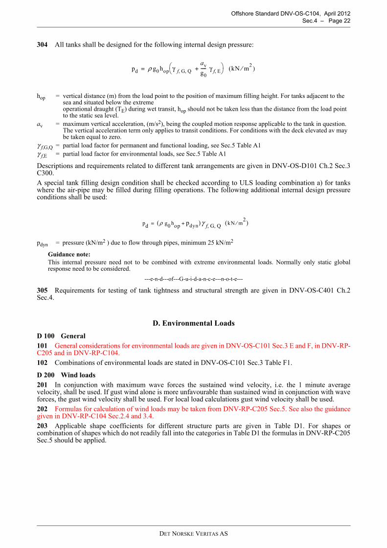
304 All tanks shall be designed for the following internal design pressure:
Descriptions and requirements related to different tank arrangements are given in DNV-OS-D101 Ch.2 Sec.3C300.A special tank filling design condition shall be checked according to ULS loading combination a) for tankswhere the air-pipe may be filled during filling operations. The following additional internal design pressureconditions shall be used:
Guidance note:This internal pressure need not to be combined with extreme environmental loads. Normally only static globalresponse need to be considered.
---e-n-d---of---G-u-i-d-a-n-c-e---n-o-t-e---
305 Requirements for testing of tank tightness and structural strength are given in DNV-OS-C401 Ch.2Sec.4.
D. Environmental Loads
D 100 General101 General considerations for environmental loads are given in DNV-OS-C101 Sec.3 E and F, in DNV-RP-C205 and in DNV-RP-C104.102 Combinations of environmental loads are stated in DNV-OS-C101 Sec.3 Table F1.
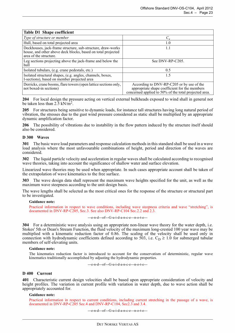
D 200 Wind loads201 In conjunction with maximum wave forces the sustained wind velocity, i.e. the 1 minute averagevelocity, shall be used. If gust wind alone is more unfavourable than sustained wind in conjunction with waveforces, the gust wind velocity shall be used. For local load calculations gust wind velocity shall be used.202 Formulas for calculation of wind loads may be taken from DNV-RP-C205 Sec.5. See also the guidancegiven in DNV-RP-C104 Sec.2.4 and 3.4.203 Applicable shape coefficients for different structure parts are given in Table D1. For shapes orcombination of shapes which do not readily fall into the categories in Table D1 the formulas in DNV-RP-C205Sec.5 should be applied.
hop = vertical distance (m) from the load point to the position of maximum filling height. For tanks adjacent to the sea and situated below the extreme operational draught (TE) during wet transit, hop should not be taken less than the distance from the load point to the static sea level.
av = maximum vertical acceleration, (m/s2), being the coupled motion response applicable to the tank in question.The vertical acceleration term only applies to transit conditions. For conditions with the deck elevated av may be taken equal to zero.
γ f,G,Q = partial load factor for permanent and functional loading, see Sec.5 Table A1γ f,E = partial load factor for environmental loads, see Sec.5 Table A1
pdyn = pressure (kN/m2 ) due to flow through pipes, minimum 25 kN/m2
pd ρ g0 hop γ f G Q, , av
g0----- γ f E,+
(kN m2⁄ )=
pd ρ g0 hop pdyn+( )γ f G Q , , kN m2⁄( )=
DET NORSKE VERITAS AS
Offshore Standard DNV-OS-C104, April 2012 Sec.4 – Page 23
204 For local design the pressure acting on vertical external bulkheads exposed to wind shall in general notbe taken less than 2.5 kN/m2.
205 For structures being sensitive to dynamic loads, for instance tall structures having long natural period ofvibration, the stresses due to the gust wind pressure considered as static shall be multiplied by an appropriatedynamic amplification factor.
206 The possibility of vibrations due to instability in the flow pattern induced by the structure itself shouldalso be considered.
D 300 Waves
301 The basic wave load parameters and response calculation methods in this standard shall be used in a waveload analysis where the most unfavourable combinations of height, period and direction of the waves areconsidered.
302 The liquid particle velocity and acceleration in regular waves shall be calculated according to recognisedwave theories, taking into account the significance of shallow water and surface elevation.
Linearized wave theories may be used when appropriate. In such cases appropriate account shall be taken ofthe extrapolation of wave kinematics to the free surface.
303 The wave design data shall represent the maximum wave heights specified for the unit, as well as themaximum wave steepness according to the unit design basis.
The wave lengths shall be selected as the most critical ones for the response of the structure or structural partto be investigated.
Guidance note:Practical information in respect to wave conditions, including wave steepness criteria and wave “stretching”, isdocumented in DNV-RP-C205, Sec.3. See also DNV-RP-C104 Sec.2.2 and 2.3.
---e-n-d---of---G-u-i-d-a-n-c-e---n-o-t-e---
304 For a deterministic wave analysis using an appropriate non-linear wave theory for the water depth, i.e.Stokes' 5th or Dean's Stream Function, the fluid velocity of the maximum long-crested 100 year wave may bemultiplied with a kinematic reduction factor of 0.86. The scaling of the velocity shall be used only inconnection with hydrodynamic coefficients defined according to 503, i.e. CD ≥ 1.0 for submerged tubularmembers of self-elevating units.
Guidance note:The kinematics reduction factor is introduced to account for the conservatism of deterministic, regular wavekinematics traditionally accomplished by adjusting the hydrodynamic properties.
---e-n-d---of---G-u-i-d-a-n-c-e---n-o-t-e---
D 400 Current
401 Characteristic current design velocities shall be based upon appropriate consideration of velocity andheight profiles. The variation in current profile with variation in water depth, due to wave action shall beappropriately accounted for.
Guidance note:Practical information in respect to current conditions, including current stretching in the passage of a wave, isdocumented in DNV-RP-C205 Sec.4 and DNV-RP-C104, Sec2.3 and 3.4.
---e-n-d---of---G-u-i-d-a-n-c-e---n-o-t-e---
Table D1 Shape coefficientType of structure or member CsHull, based on total projected area 1.0Deckhouses, jack-frame structure, sub-structure, draw-works house, and other above deck blocks, based on total projected area of the structure.
1.1
Leg sections projecting above the jack-frame and below the hull
See DNV-RP-C205.
Isolated tubulars, (e.g. crane pedestals, etc.) 0.5Isolated structural shapes, (e.g. angles, channels, boxes, I-sections), based on member projected area
1.5
Derricks, crane booms, flare towers (open lattice sections only, not boxed-in sections)
According to DNV-RP-C205 or by use of the appropriate shape coefficient for the members
concerned applied to 50% of the total projected area.
DET NORSKE VERITAS AS
Offshore Standard DNV-OS-C104, April 2012 Sec.4 – Page 24
D 500 Wave and current loads
501 Wave and current loads should be calculated using Morison’s equation.Guidance note:For information regarding use of Morison’s equation see DNV-RP-C205, Sec.6 and DNV-RP-C104, Sec.3.4.
---e-n-d---of---G-u-i-d-a-n-c-e---n-o-t-e---
502 Vector addition of the wave and current induced particle velocities should be used for calculation of thecombined wave and current drag force. If available, computations of the total particle velocities andacceleration based on more exact theories of wave and current interaction may be preferred.
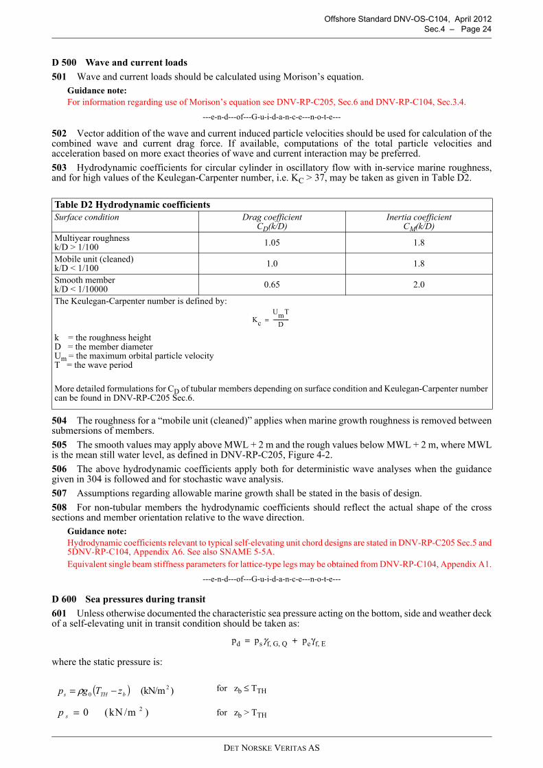
503 Hydrodynamic coefficients for circular cylinder in oscillatory flow with in-service marine roughness,and for high values of the Keulegan-Carpenter number, i.e. KC > 37, may be taken as given in Table D2.
504 The roughness for a “mobile unit (cleaned)” applies when marine growth roughness is removed betweensubmersions of members.
505 The smooth values may apply above MWL + 2 m and the rough values below MWL + 2 m, where MWLis the mean still water level, as defined in DNV-RP-C205, Figure 4-2.
506 The above hydrodynamic coefficients apply both for deterministic wave analyses when the guidancegiven in 304 is followed and for stochastic wave analysis.
507 Assumptions regarding allowable marine growth shall be stated in the basis of design.
508 For non-tubular members the hydrodynamic coefficients should reflect the actual shape of the crosssections and member orientation relative to the wave direction.
Guidance note:Hydrodynamic coefficients relevant to typical self-elevating unit chord designs are stated in DNV-RP-C205 Sec.5 and5DNV-RP-C104, Appendix A6. See also SNAME 5-5A.Equivalent single beam stiffness parameters for lattice-type legs may be obtained from DNV-RP-C104, Appendix A1.
---e-n-d---of---G-u-i-d-a-n-c-e---n-o-t-e---
D 600 Sea pressures during transit
601 Unless otherwise documented the characteristic sea pressure acting on the bottom, side and weather deckof a self-elevating unit in transit condition should be taken as:
where the static pressure is:
Table D2 Hydrodynamic coefficientsSurface condition Drag coefficient
CD(k/D)Inertia coefficient
CM(k/D)Multiyear roughnessk/D > 1/100 1.05 1.8
Mobile unit (cleaned)k/D < 1/100 1.0 1.8
Smooth memberk/D < 1/10000 0.65 2.0
The Keulegan-Carpenter number is defined by:
k = the roughness heightD = the member diameterUm = the maximum orbital particle velocityT = the wave period
More detailed formulations for CD of tubular members depending on surface condition and Keulegan-Carpenter number can be found in DNV-RP-C205 Sec.6.
for zb ≤ TTH
for zb > TTH
Kc
UmT
D-------------=
pd psγf G Q, , peγf E,+=
( ) )(kN/m 20 bTHs zTgp −= ρ
)kN /m(0 2=sp
DET NORSKE VERITAS AS
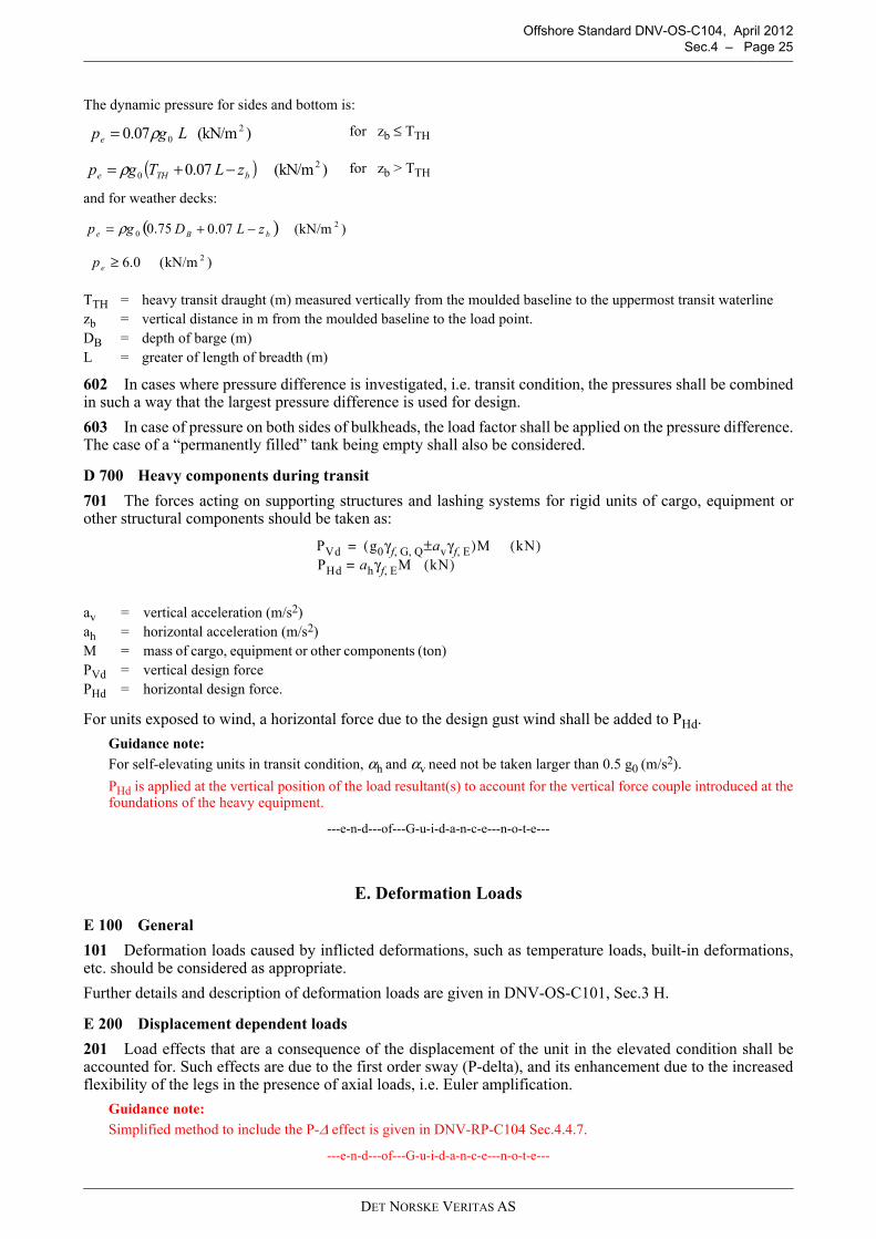
Offshore Standard DNV-OS-C104, April 2012 Sec.4 – Page 25
602 In cases where pressure difference is investigated, i.e. transit condition, the pressures shall be combinedin such a way that the largest pressure difference is used for design.
603 In case of pressure on both sides of bulkheads, the load factor shall be applied on the pressure difference.The case of a “permanently filled” tank being empty shall also be considered.
D 700 Heavy components during transit
701 The forces acting on supporting structures and lashing systems for rigid units of cargo, equipment orother structural components should be taken as:
For units exposed to wind, a horizontal force due to the design gust wind shall be added to PHd.
Guidance note:
For self-elevating units in transit condition, αh and αv need not be taken larger than 0.5 g0 (m/s2).
PHd is applied at the vertical position of the load resultant(s) to account for the vertical force couple introduced at thefoundations of the heavy equipment.
---e-n-d---of---G-u-i-d-a-n-c-e---n-o-t-e---
E. Deformation Loads
E 100 General
101 Deformation loads caused by inflicted deformations, such as temperature loads, built-in deformations,etc. should be considered as appropriate.
Further details and description of deformation loads are given in DNV-OS-C101, Sec.3 H.
E 200 Displacement dependent loads
201 Load effects that are a consequence of the displacement of the unit in the elevated condition shall beaccounted for. Such effects are due to the first order sway (P-delta), and its enhancement due to the increasedflexibility of the legs in the presence of axial loads, i.e. Euler amplification.
Guidance note:
Simplified method to include the P-Δ effect is given in DNV-RP-C104 Sec.4.4.7.
---e-n-d---of---G-u-i-d-a-n-c-e---n-o-t-e---
The dynamic pressure for sides and bottom is:
for zb ≤ TTH
for zb > TTH
and for weather decks:
TTH = heavy transit draught (m) measured vertically from the moulded baseline to the uppermost transit waterlinezb = vertical distance in m from the moulded baseline to the load point.DB = depth of barge (m) L = greater of length of breadth (m)
av = vertical acceleration (m/s2)ah = horizontal acceleration (m/s2)M = mass of cargo, equipment or other components (ton)PVd = vertical design forcePHd = horizontal design force.
)(kN/m 07.0 20 Lgpe ρ=
( ) )(kN/m 07.0 20 bTHe zLTgp −+= ρ
( 75.00e gp = ρ ) )(kN/m07.0 2bB zLD −+
)kN/m(0.6 2≥ep
PVd g0γf G Q, , avγf E,±( )M kN( ) PHd ah= γf E, M kN( )
=
DET NORSKE VERITAS AS
Offshore Standard DNV-OS-C104, April 2012 Sec.4 – Page 26
F. Accidental Loads
F 100 General101 The following ALS events shall be considered in respect to the structural design of a self-elevating unit:
— collision— dropped objects (e.g. from crane handling)— fire— explosion— unintended flooding during transit.
102 Requirements and guidance on accidental loads are given in DNV-OS-C101 and generic loads are givenin DNV-OS-A101.
G. Fatigue Loads
G 100 General101 Repetitive loads, which may lead to possible significant fatigue damage, shall be evaluated. Thefollowing listed sources of fatigue loads shall, where relevant, be considered:
— waves (including loads caused by slamming and variable (dynamic) pressures)— wind (especially when vortex induced vibrations may occur)— currents (especially when vortex induced vibrations may occur)— mechanical vibration (e.g. caused by operation of machinery)— mechanical loading and unloading (e.g. due to jacking or crane operations).
The effects of both local and global dynamic response shall be properly accounted for when determiningresponse distributions related to fatigue loads.102 Further considerations with respect to fatigue loads are given in DNV-RP-C203.
H. Combination of Loads
H 100 General101 Load combinations for the design limit states are, in general given in DNV-OS-C101 Sec.3. Specific loadfactors for self-elevating units for the ULS are given in Sec.5.102 Structural strength shall be evaluated considering all relevant, realistic load conditions and combinations.Scantlings shall be determined on the basis of criteria that combine, in a rational manner, the effects of relevantglobal and local responses for each individual structural element.103 A sufficient number of load conditions shall be evaluated to ensure that the characteristic largest (orsmallest) response, for the appropriate return period, has been established.
Guidance note:For example, maximum global, characteristic responses for a self-elevating unit may occur in environmentalconditions that are not associated with the characteristic, largest, wave height. In such cases, wave period andassociated wave steepness parameters are more likely to be governing factors in the determination of maximum andminimum responses.
---e-n-d---of---G-u-i-d-a-n-c-e---n-o-t-e---
DET NORSKE VERITAS AS
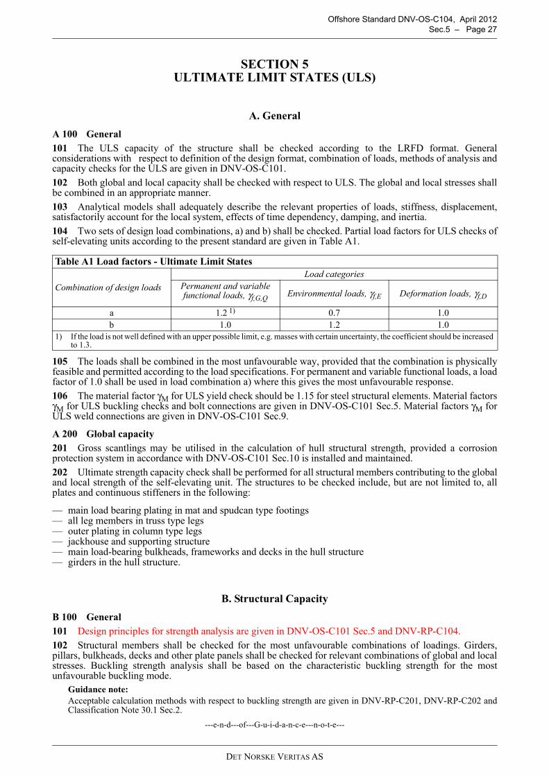
Offshore Standard DNV-OS-C104, April 2012 Sec.5 – Page 27
SECTION 5ULTIMATE LIMIT STATES (ULS)
A. General
A 100 General
101 The ULS capacity of the structure shall be checked according to the LRFD format. Generalconsiderations with respect to definition of the design format, combination of loads, methods of analysis andcapacity checks for the ULS are given in DNV-OS-C101.
102 Both global and local capacity shall be checked with respect to ULS. The global and local stresses shallbe combined in an appropriate manner.
103 Analytical models shall adequately describe the relevant properties of loads, stiffness, displacement,satisfactorily account for the local system, effects of time dependency, damping, and inertia.
104 Two sets of design load combinations, a) and b) shall be checked. Partial load factors for ULS checks ofself-elevating units according to the present standard are given in Table A1.
105 The loads shall be combined in the most unfavourable way, provided that the combination is physicallyfeasible and permitted according to the load specifications. For permanent and variable functional loads, a loadfactor of 1.0 shall be used in load combination a) where this gives the most unfavourable response.
106 The material factor γM for ULS yield check should be 1.15 for steel structural elements. Material factorsγM for ULS buckling checks and bolt connections are given in DNV-OS-C101 Sec.5. Material factors γM forULS weld connections are given in DNV-OS-C101 Sec.9.
A 200 Global capacity
201 Gross scantlings may be utilised in the calculation of hull structural strength, provided a corrosionprotection system in accordance with DNV-OS-C101 Sec.10 is installed and maintained.
202 Ultimate strength capacity check shall be performed for all structural members contributing to the globaland local strength of the self-elevating unit. The structures to be checked include, but are not limited to, allplates and continuous stiffeners in the following:
— main load bearing plating in mat and spudcan type footings— all leg members in truss type legs— outer plating in column type legs— jackhouse and supporting structure— main load-bearing bulkheads, frameworks and decks in the hull structure— girders in the hull structure.
B. Structural Capacity
B 100 General
101 Design principles for strength analysis are given in DNV-OS-C101 Sec.5 and DNV-RP-C104.
102 Structural members shall be checked for the most unfavourable combinations of loadings. Girders,pillars, bulkheads, decks and other plate panels shall be checked for relevant combinations of global and localstresses. Buckling strength analysis shall be based on the characteristic buckling strength for the mostunfavourable buckling mode.
Guidance note:Acceptable calculation methods with respect to buckling strength are given in DNV-RP-C201, DNV-RP-C202 andClassification Note 30.1 Sec.2.
---e-n-d---of---G-u-i-d-a-n-c-e---n-o-t-e---
Table A1 Load factors - Ultimate Limit States
Combination of design loads
Load categoriesPermanent and variable functional loads, γf,G,Q
Environmental loads, γf,E Deformation loads, γf,D
a 1.2 1) 0.7 1.0b 1.0 1.2 1.0
1) If the load is not well defined with an upper possible limit, e.g. masses with certain uncertainty, the coefficient should be increased to 1.3.
DET NORSKE VERITAS AS
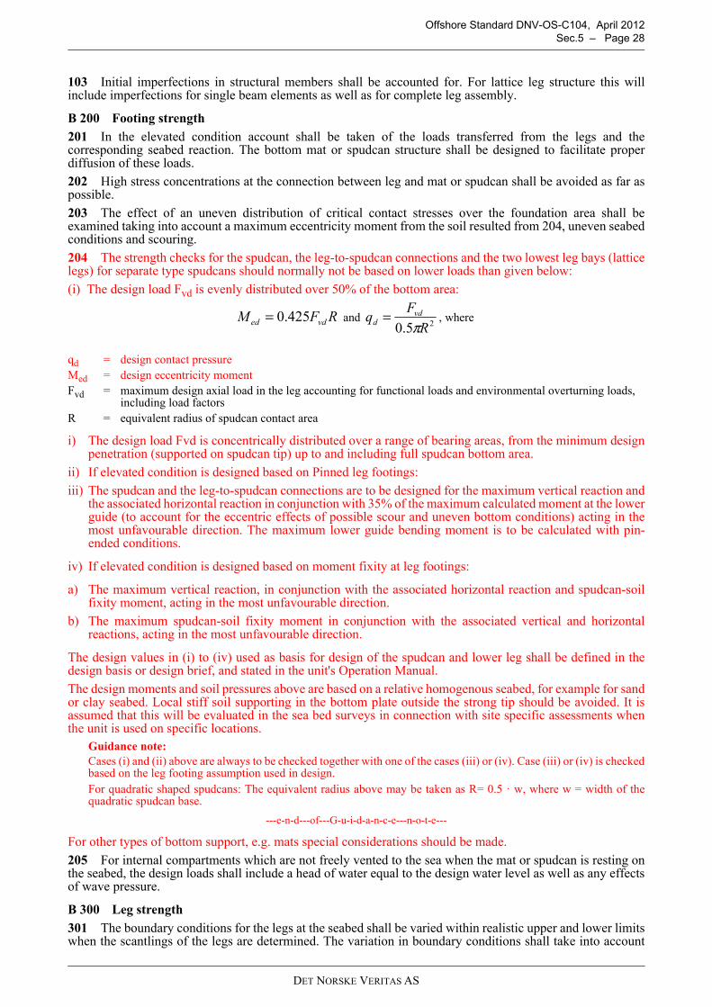
Offshore Standard DNV-OS-C104, April 2012 Sec.5 – Page 28
103 Initial imperfections in structural members shall be accounted for. For lattice leg structure this willinclude imperfections for single beam elements as well as for complete leg assembly.
B 200 Footing strength
201 In the elevated condition account shall be taken of the loads transferred from the legs and thecorresponding seabed reaction. The bottom mat or spudcan structure shall be designed to facilitate properdiffusion of these loads.
202 High stress concentrations at the connection between leg and mat or spudcan shall be avoided as far aspossible.
203 The effect of an uneven distribution of critical contact stresses over the foundation area shall beexamined taking into account a maximum eccentricity moment from the soil resulted from 204, uneven seabedconditions and scouring.
204 The strength checks for the spudcan, the leg-to-spudcan connections and the two lowest leg bays (latticelegs) for separate type spudcans should normally not be based on lower loads than given below:
(i) The design load Fvd is evenly distributed over 50% of the bottom area:
i) The design load Fvd is concentrically distributed over a range of bearing areas, from the minimum designpenetration (supported on spudcan tip) up to and including full spudcan bottom area.
ii) If elevated condition is designed based on Pinned leg footings:
iii) The spudcan and the leg-to-spudcan connections are to be designed for the maximum vertical reaction andthe associated horizontal reaction in conjunction with 35% of the maximum calculated moment at the lowerguide (to account for the eccentric effects of possible scour and uneven bottom conditions) acting in themost unfavourable direction. The maximum lower guide bending moment is to be calculated with pin-ended conditions.
iv) If elevated condition is designed based on moment fixity at leg footings:
a) The maximum vertical reaction, in conjunction with the associated horizontal reaction and spudcan-soilfixity moment, acting in the most unfavourable direction.
b) The maximum spudcan-soil fixity moment in conjunction with the associated vertical and horizontalreactions, acting in the most unfavourable direction.
The design values in (i) to (iv) used as basis for design of the spudcan and lower leg shall be defined in thedesign basis or design brief, and stated in the unit's Operation Manual.
The design moments and soil pressures above are based on a relative homogenous seabed, for example for sandor clay seabed. Local stiff soil supporting in the bottom plate outside the strong tip should be avoided. It isassumed that this will be evaluated in the sea bed surveys in connection with site specific assessments whenthe unit is used on specific locations.
Guidance note:Cases (i) and (ii) above are always to be checked together with one of the cases (iii) or (iv). Case (iii) or (iv) is checkedbased on the leg footing assumption used in design.For quadratic shaped spudcans: The equivalent radius above may be taken as R= 0.5 · w, where w = width of thequadratic spudcan base.
---e-n-d---of---G-u-i-d-a-n-c-e---n-o-t-e---
For other types of bottom support, e.g. mats special considerations should be made.
205 For internal compartments which are not freely vented to the sea when the mat or spudcan is resting onthe seabed, the design loads shall include a head of water equal to the design water level as well as any effectsof wave pressure.
B 300 Leg strength
301 The boundary conditions for the legs at the seabed shall be varied within realistic upper and lower limitswhen the scantlings of the legs are determined. The variation in boundary conditions shall take into account
qd = design contact pressure Med = design eccentricity moment Fvd = maximum design axial load in the leg accounting for functional loads and environmental overturning loads,
including load factorsR = equivalent radius of spudcan contact area
RFM vded 425.0= and 25.0 R
Fq vd
d π= , where
DET NORSKE VERITAS AS
Offshore Standard DNV-OS-C104, April 2012 Sec.5 – Page 29
uncertainties in the estimation of soil properties, non-linear soil-structure interaction, effects due to repeatedloadings, possible scouring, etc.302 When determining the forces and moments in the legs, different positions of the hull supports along thelegs shall be considered.303 Due attention shall be paid to the position and duration of load transfer between the leg and hull,including the shear force in the leg between supporting points in the hull structure.304 Lattice-type legs shall be checked against overall buckling, buckling of single elements and punchingstrength of the nodes, see DNV-OS-C101 Sec.5.305 Bottom impact forces occurring during installation and retrieval conditions shall be satisfactorilyaccounted in the design.
Guidance note:A simplified analytical methodology relevant to installation and retrieval conditions is described in DNV-RP-C104.
---e-n-d---of---G-u-i-d-a-n-c-e---n-o-t-e---
B 400 Jackhouse support strength401 Special attention shall be paid to the means for the leg support, the jackhouses, the support of thejackhouse to the main hull, and the main load transfer girders between the jackhouses.
B 500 Hull strength501 Scantlings of the hull shall be checked for the transit conditions with external hydrostatic pressure andinertia forces on the legs as well as for the pre-loading and elevated conditions, see DNV-OS-C101 Sec.5.
C. Scantlings and Weld Connections
C 100 General101 Minimum scantlings for plate, stiffeners and girders are given in DNV-OS-C101 Sec.5.102 The requirements for weld connections are given in DNV-OS-C101 Sec.9.
DET NORSKE VERITAS AS
Offshore Standard DNV-OS-C104, April 2012 Sec.6 – Page 30
SECTION 6FATIGUE LIMIT STATES (FLS)
A. General
A 100 General101 General requirements for the FLS are given in DNV-OS-C101 Sec.6. Guidance concerning fatigue lifecalculation may be found in DNV-RP-C203 and DNV-RP-C104 Sec.7.102 The design fatigue life of the unit shall be minimum 20 years.103 For units intended to follow normal inspection requirements according to class requirements, i.e. 5 yearlyinspections in dry dock or sheltered waters, a Design Fatigue Factor (DFF) of 1.0 may be applied for accessiblemembers. For not accessible members DFF shall be applied to structural elements according to the principlesin DNV-OS-C101.104 Units intended to stay on location for prolonged survey period, i.e. without planned dry dock or shelteredwater inspection, shall comply with the requirements given in Appendix A.105 Assumptions related to the resistance parameters adopted in the fatigue design, e.g. with respect tocorrosion protection, shall be consistent with the unit's in-service inspection and maintenance plans (see DNV-RP-C203).106 Local effects, for example, due to:
— slamming— sloshing— vortex shedding— dynamic pressures
shall be included in the fatigue damage assessment when relevant.107 In the assessment of fatigue resistance, relevant consideration shall be given to the effects of stressconcentrations, including those occurring as a result of:
— fabrication tolerances, including due regard to tolerances in way of connections involved in fabricationsequences or section joints
— cut-outs— details at connections of structural sections (e.g. cut-outs to facilitate construction welding)— attachments.
108 Local, detailed finite element analysis of critical connections (e.g. leg and footing connection) should beperformed in order to identify local stress distributions, appropriate SCFs, and/or extrapolated stresses to beutilised in the fatigue evaluation. Dynamic stress variations through the plate thickness shall be checked andconsidered in such evaluations when relevant, see DNV-RP-C203 Sec.2 for further details.109 Principal stresses (see DNV-RP-C203 Sec.2.2) should be utilised in the evaluation of fatigue responses.
B. Fatigue Analysis
B 100 General101 The required models and methods for fatigue analysis for self-elevating units or jack-ups are dependenton type of operation, environment and design type of the unit. For units operating at deeper waters where thefirst natural periods are in a range with significant wave energy, e.g. for natural periods higher than 3 s, thedynamic structural response need to be considered in the fatigue analysis.
B 200 World-wide operation201 For world wide operation the analyses shall be performed utilising environmental data (e.g. scatterdiagram, spectrum) given in DNV-RP-C205. The North Atlantic scatter diagram shall be utilised.
B 300 Restricted operation301 The analyses shall be performed utilising relevant site specific environmental data for the area(s) the unitwill be operated. The restrictions shall be described in the operation manual for the unit.
B 400 Simplified fatigue analysis401 Simplified fatigue analysis may be performed in order to establish the general acceptability of fatigueresistance, or as a screening process to identify the most critical details to be considered in a stochastic fatigueanalysis, see B500.
DET NORSKE VERITAS AS
Offshore Standard DNV-OS-C104, April 2012 Sec.6 – Page 31
402 Simplified fatigue analyses should be performed utilising appropriate conservative design parameters.Normally a two-parameter, Weibull distribution (see DNV-RP-C203 Sec.2.14.) may be utilised to describe thelong-term stress range distribution, giving the following extreme stress range:
403 When the simplified fatigue evaluation involves utilisation of the dynamic stress responses resultingfrom the global analysis, e.g. 100 years, the response should be suitably scaled to the return period of the basis,minimum fatigue life of the unit. In such cases, scaling may be undertaken utilising the appropriate factor foundfrom the following:
B 500 Stochastic fatigue analysis501 Stochastic fatigue analyses shall be based upon recognised procedures and principles utilising relevantsite specific data or world wide environmental data.502 Simplified fatigue analyses should be used as a “screening” process to identify locations for which adetailed, stochastic fatigue analysis should be undertaken.503 Fatigue analyses shall include consideration of the directional probability of the environmental data.Providing that it can be satisfactorily checked, scatter diagram data may be considered as being directionallyspecific. Scatter diagram for world wide operations (North Atlantic scatter diagram) is given in DNV-RP-C205. Relevant wave spectra and energy spreading shall be utilised. Normally a Pierson-Moskowitch spectrumand a cos4 spreading function is utilised in the evaluation of self-elevating units. Further details are given inDNV-RP-C104.504 Structural response shall be determined based upon analyses of an adequate number of wave directions.Generally a maximum radial spacing of 15 degrees should be considered. Transfer functions should beestablished based upon consideration of a sufficient number of periods, such that the number, and values of theperiods analysed:
— adequately cover the wave data— satisfactorily describe transfer functions at, and around, the wave ‘cancellation’ and ‘amplifying’ periods
(consideration should be given to take account that such ‘cancellation’ and ‘amplifying’ periods may bedifferent for different elements within the structure)
— satisfactorily describe transfer functions at, and around, the relevant excitation periods of the structure.
505 Stochastic fatigue analyses utilising simplified structural model representations of the unit (e.g. a spaceframe model) may form basis for identifying locations for which a stochastic fatigue analysis, utilising adetailed model of the structure, should be performed (e.g. at critical intersections).
n0 = the total number of stress variations during the lifetime of the structure= extreme stress range that is exceeded once out of n0 stress variations.
h = the shape parameter of the Weibull stress range distribution, see e.g. DNV-RP-C104 Sec.7.9 a = the intercept of the design S-N curve with the log N axis, see DNV-RP-C203 Sec.2.3Γ(1+m/h) = is the complete gamma function, see DNV-RP-C203 Sec.2.14m = the inverse slope of the S-N curve, see DNV-RP-C203 Sec.2.14DFF = Design Fatigue Factor.
ni = the number of stress variations in i years appropriate to the global analysis= the extreme stress range that is exceeded once out of ni stress variations.
Δσn0
n0( )ln( )1h---
DFF( )1m----
----------------------- a
n0Γ 1mh----+
-----------------------------
1m----
=
Δσn0The extreme stress amplitude
Δσampl_n0 is thus given by ( Δσn0
/ 2 )
Δσn0Δσni
=n0log
nilog-------------
1h---
Δσni
DET NORSKE VERITAS AS
Offshore Standard DNV-OS-C104, April 2012 Sec.7 – Page 32
SECTION 7ACCIDENTAL LIMIT STATES (ALS)
A. General
A 100 General101 ALS shall be assessed for relevant accidental events. Principally satisfactory protection againstaccidental damage should be obtained by the following two means:
— low damage probability— acceptable damage consequences.
Further information about safety principles and arrangements with respect to design towards accidental eventsare given in DNV-OS-A101.102 The capability of the structure to redistribute loads during and after accidents should be considered whendesigning the unit. After damage requiring immediate repair, the unit is to resist functional and environmental loads correspondingto a return period of one year.
Guidance note:Energy absorption by impact types of accidental events requires the structure to behave in a ductile manner. Measuresto obtain adequate ductility are:
- make the strength of connections of primary members in excess of that of the member- provide redundancy in the structure, so that alternate load redistribution paths may be developed- avoid dependence on energy absorption in slender members with a non-ductile post buckling behaviour- avoid pronounced weak sections and abrupt change in strength or stiffness- use non-brittle materials.
---e-n-d---of---G-u-i-d-a-n-c-e---n-o-t-e---
103 The loads and consequential damage due to accidental events such as:
— collision— dropped objects (e.g. from crane handling)— fire— explosion— unintended flooding during transit
shall be considered to avoid loss of floatability or capsizing during transit, on-bottom instability in elevatedoperation or survival conditions, pollution or loss of human life. Requirements for compartmentation andfloating stability are given in DNV-OS-C301.104 Analysis and requirements to satisfy strength criteria are given in the present standard and in DNV-OS-C101 Sec.7. 105 The damage consequences of accidental events other than those listed in 103 shall if relevant be speciallyconsidered in each case applying an equivalent standard of safety.
B. Collisions
B 100 General101 Collision by a supply vessel against a leg of a self-elevating unit shall be considered for all elements thatmay be hit either by sideways, bow or stern collision. The vertical extent of the collision zone shall be basedon the depth and draught of visiting supply vessels.
Guidance note:Simplified procedures for calculation of vessel impact on self-elevating unit legs may be found in DNV-RP-C104Sec.8.
---e-n-d---of---G-u-i-d-a-n-c-e---n-o-t-e---
102 A collision will normally only cause local damage of the leg. However, the global strength andoverturning stability of the unit shall also be checked. With lattice type legs the damaged chord or bracing andconnections may be assumed to be non-effective for check of residual strength of the unit after collision.103 Assessment of dynamic effects and non-linear structural response (geometrical and material) should beperformed as part of the impact evaluation.
DET NORSKE VERITAS AS
Offshore Standard DNV-OS-C104, April 2012 Sec.7 – Page 33
C. Dropped Objects
C 100 General
101 Critical areas for dropped objects shall be determined on the basis of the actual movement of potentialdropped objects (e.g. crane or other lifting operation mass) relative to the structure of the unit itself. Where adropped object is a relevant accidental event, the impact energy shall be established and the structuralconsequences of the impact assessed.
102 A dropped object impact against a chord or bracing will normally cause complete failure of the elementor its connections. These parts should then be assumed to be non-effective for the check of the residual strengthof the unit after the dropped object impact.
103 Critical areas for dropped objects shall be determined on the basis of the actual movement of loadsassuming a minimum drop direction within an angle with the vertical direction:
— 5° in air— 15° in water.
Dropped objects shall be considered for vital structural elements of the unit within the areas given above.
D. Fires
D 100 General
101 A structure that is subjected to a fire shall have sufficient structural capacity until completed evacuation.The following fire scenarios shall be considered:
— jet fires— fire inside or on the hull— fire on the sea surface.
102 Further requirements concerning accidental limit state events involving fire is given in DNV-OS-A101.
103 Structural assessment with respect to fire may be omitted provided fire protection requirements made inDNV-OS-D301 are met.
E. Explosions
E 100 General
101 With respect to design loads resulting from explosions, one or more of the following design philosophiesare relevant:
— ensure that hazardous locations are located in unconfined (open) locations and that sufficient shieldingmechanisms (e.g. blast walls) are installed
— locate hazardous areas in partially confined locations and design utilising the resulting, relatively smalloverpressures
— locate hazardous areas in enclosed locations and install pressure relief mechanisms (e.g. blast panels) anddesign for the resulting overpressure.
102 As far as practicable, structural design accounting for large plate field rupture resulting from explosionloads should be avoided due to the uncertainties of the loads and the consequences of the rupture itself.
103 Structural support of blast walls and the transmission of the blast loads into main structural membersshall be evaluated when relevant.
F. Unintended Flooding
F 100 General
101 For the transit condition, structural effects as a results of heeling of the unit after damage flooding asdescribed in DNV-OS-C301 shall be accounted for in the structural strength assessment. Boundaries whichshall remain watertight after unintended flooding shall be checked for external water pressure.
102 The unit shall be designed for environmental condition corresponding to 1 year return period afterdamage flooding, see DNV-OS-C101.
DET NORSKE VERITAS AS
Offshore Standard DNV-OS-C104, April 2012 Sec.7 – Page 34
Guidance note:The environmental loads may be disregarded if the material factor γM is set to 1.33.
---e-n-d---of---G-u-i-d-a-n-c-e---n-o-t-e---
103 Local exceeding of the structural resistance level may be acceptable provided redistribution of forces dueto yielding, buckling and fracture is accounted for.104 Wave pressure, slamming forces and green sea shall be accounted for in all relevant areas. Local damagemay be accepted provided progressive structural collapse and damage of vital equipment is avoided.105 Position of air-intakes and openings to areas with vital equipment which need to be available during anemergency situation e.g. emergency generators, shall be considered taking into account the wave elevation ina 1 year storm condition.
DET NORSKE VERITAS AS
Offshore Standard DNV-OS-C104, April 2012 Sec.8 – Page 35
SECTION 8SPECIAL CONSIDERATIONS
A. General
A 100 General
101 Some special items to be considered in relation to robust design and safe operation of self-elevating unitsare described in this section.
B. Pre-load Capacity
B 100 General
101 Minimum required pre-load capacity with reference to the global strength and the seabed designassumptions for units with separate footings shall be accounted for in the design.
Guidance note:It should be noted that actual soil conditions at operation sites may require higher pre-loads than those set up by theleg strength, e.g. to secure against sudden penetration.
---e-n-d---of---G-u-i-d-a-n-c-e---n-o-t-e---
102 The assessment of pre-load capacity given in 103 and 104 should be performed with the characteristicfunctional and environmental loads, i.e. without load factors.
103 Units with separate footings which are designed for a pinned leg-bottom connection are to have acapability to pre-load the legs up to at least 100% of the maximum design axial loads in the legs accounting forfunctional loads and environmental overturning loads.
For units that shall operate in soil conditions where exceeding of the soil capacity will result in largepenetrations, a pre-load higher than the maximum survival axial load case axial load will be required. Examplesof such soils are generally soft clays, or conditions where hard soils are underlain by softer soils and there is arisk of a punch-through failure.
A recommended approach for determination of required pre-load is given in Classification Note 30.4.
104 Units with separate footings where the design is based on a specified moment restraint of the legs at theseabed are to have a capability to pre-load the legs up to a level which shall account for the maximum designaxial loads in the legs due to functional loads and environmental overturning loads plus the specified momentrestraint at the bottom.
In lieu of a detailed soil/structure interaction analysis the required pre-load may in this case be determined bythe following factor:
For cohesive soils, e.g. clay:
For cohesionless soils, e.g. sand:
105 For cohesionless soils, the above requirement to pre-load capacity may be departed from in case wherea jetting system is installed which will provide penetration to full soil contact of the total spudcan area.
FVP = minimum required pre-load on one legFV = maximum design axial load in the leg accounting for functional loads and environmental overturning loadsMU = minimum design moment restraint of the leg at the seabedA = area of spudcan in contact with soilR = equivalent radius of spudcan contact area.
FVP
FV---------- 1
12 A
πR2
-----------MU
FV----------–
--------------------------------=
FVP
FV---------- 1
12 A
πR2
-----------MU
FV----------–
--------------------------------
2
=
DET NORSKE VERITAS AS
Offshore Standard DNV-OS-C104, April 2012 Sec.8 – Page 36
106 The potential of scour at each location should be evaluated. If scour takes place, the beneficial effect ofpre-loading related to moment restraint capacity may be destroyed. At locations with scour potential, scourprotection should normally be provided in order to rely on a permanent moment restraint.
C. Overturning Stability
C 100 General
101 The safety against overturning is determined by the equation:
Guidance note:It is allowed to use load factor = 1.0 on all loads contributing to MS and MO in the overturning stability check above. If the design is based on a specified moment restraint of the legs at the seabed, the calculated leg footing moments arenot to be included in MS above.
---e-n-d---of---G-u-i-d-a-n-c-e---n-o-t-e---
102 The stabilising moment due to functional loads shall be calculated with respect to the assumed axis ofrotation, and with the unit's lateral deflections taken into consideration.
For self-elevating units with separate footings the axis of rotation may, in lieu of a detailed soil-structureinteracting analysis, be assumed to be a horizontal axis intersecting the axis of two of the legs. It may furtherbe assumed that the vertical position of the axis of rotation is located at a distance above the spudcan tipequivalent to the lesser of:
— half the maximum predicted penetration or— half the height of the spudcan.
For self-elevating units with mat support, the location of the axis of rotation may have to be speciallyconsidered.
103 The overturning moment due to wind, waves and current should be calculated with respect to the axis ofrotation defined in 102.
The overturning stability shall be calculated for the most unfavourable direction and combination ofenvironmental and functional loads according to the load plan for the unit. The dynamic amplification of thecombined wave and current load effect shall be taken into account.
104 The lower ends of separate legs shall be prevented from sideway slipping by ensuring sufficienthorizontal leg and soil support.
D. Air Gap
D 100 General
101 Clearance between the hull structure and the wave crest is normally to be ensured for the operatingposition.
102 The requirement to the length of the leg is that the distance between the lower part of the deck structurein the operating position and the crest of the maximum design wave, including astronomical and storm tides,is not to be less than 10% of the combined storm tide, astronomical tide and height of the design wave abovethe mean low water level, or 1.2 m, whichever is smaller. Expected subsidence of the structure shall be takeninto account.
103 Crest elevation above still water level is given in Fig.1.
104 A smaller distance may be accepted if wave impact forces on the deck structure are taken into accountin the strength and overturning analysis.
105 Clearance between the structure and wave shall be ensured in floating condition for appurtenances suchas helicopter deck, etc.
MO = overturning moment, i.e. caused by environmental loadsMS = stabilising moment, i.e. caused by functional loadsγs = safety coefficient against overturning
= 1.1.
γs
Ms
MO---------≤
DET NORSKE VERITAS AS
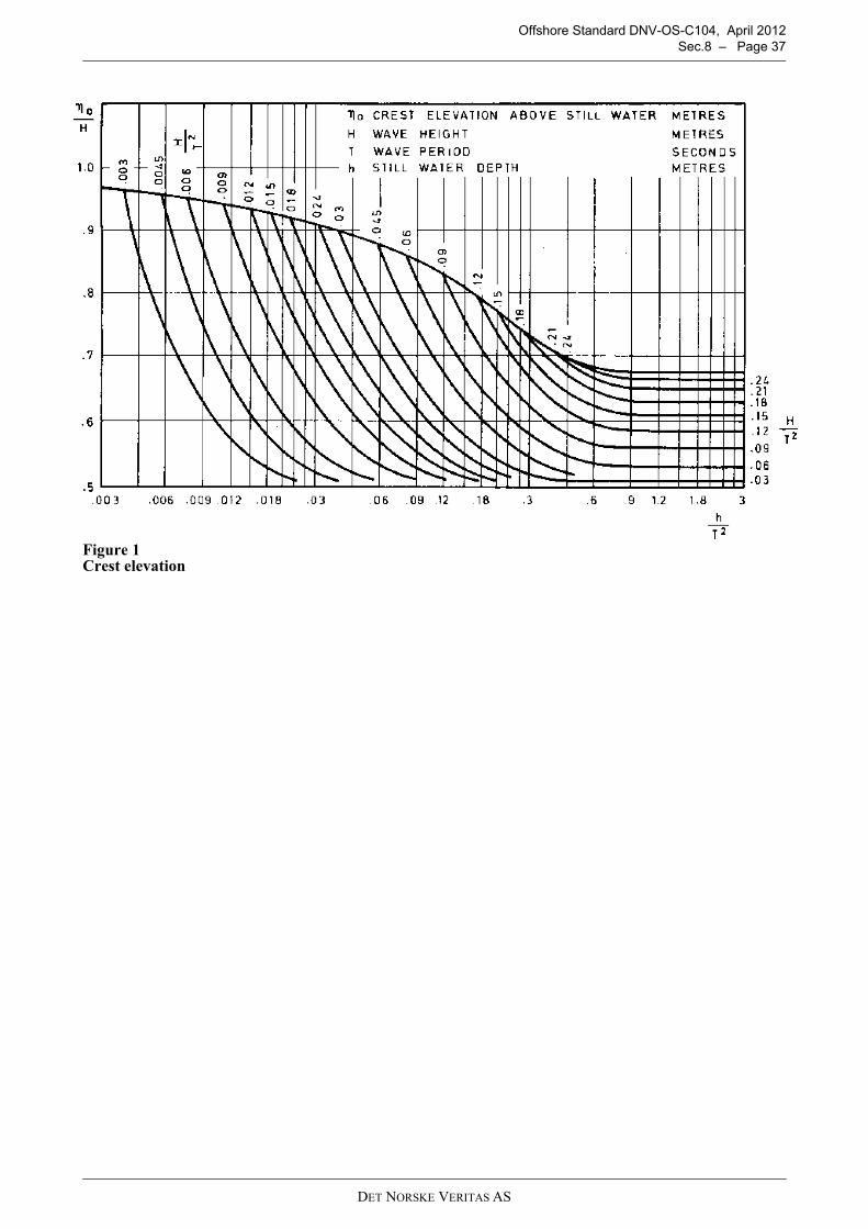
Offshore Standard DNV-OS-C104, April 2012 Sec.8 – Page 37
Figure 1 Crest elevation
DET NORSKE VERITAS AS
Offshore Standard DNV-OS-C104, April 2012 App.A – Page 38
APPENDIX A PERMANENTLY INSTALLED SELF-ELEVATING UNITS
A. Introduction
A 100 General101 The requirements and guidance given in this Appendix are supplementary requirements for units that areintended to stay on location for prolonged periods, normally more than 5 years.102 The requirements apply to all types of self-elevating units.103 Permanently installed self-elevating units shall be designed or documented for the site specificenvironmental and soil conditions. Fatigue properties and facilities for survey on location shall be speciallyconsidered.104 Adequate corrosion protection shall be implemented to cover the entire prolonged operation period.
B. Fatigue
B 100 General101 Design Fatigue Factors (DFF) are introduced as fatigue safety factors. DFF shall be applied to structuralelements according to the principles in DNV-OS-C101. 102 Fatigue safety factors applied for permanently installed self-elevating units shall be given dependent onthe criticality of the detail and accessibility for inspection and repair. Special considerations should be madefor the leg in the splash zone, submerged parts legs and spudcan, and possible inaccessible parts of the spudcan.103 The fatigue analysis should focus on members that are essential to the overall structural integrity of theunit. Fatigue susceptible areas may include:
— the leg to hull holding system— the leg members and joints in the vicinity of the upper and lower guides— the leg members and joints in the splashing zone— the leg members and joints in the lower part of the leg near the spudcan— the spudcan to leg connection.
Guidance note:See DNV-OS-C101 Sec.10 B200 with respect to vertical extent of splash zone.
---e-n-d---of---G-u-i-d-a-n-c-e---n-o-t-e---
C. Inspection and Maintenance
C 100 Facilities for survey101 Surveys may be carried out on location based on agreed procedures outlined in a maintenance systemand survey arrangement, without interrupting the function of the unit. The following matters shall be taken intoconsideration to be able to carry out surveys on location:
— arrangements and methods for survey of hull, legs and seabed foundation structure— corrosion protection of hull, legs and seabed foundation structure— underwater cleaning facilities.
102 The In Service Inspection program (IIP) should reflect possible stress concentrations in critical areas,fatigue criticality, and the previous operational and inspection histories.
DET NORSKE VERITAS AS