Embed Size (px)
Citation preview
DOCUMENT RESUME
ED 220 619 CE 033 477
TITLE Military Curriculum Materials for Vocational and. Technical Education. Arc Welding7Pipe, 3-25:
INSTITUTION Naval Construction Training Center, Port Hueneme,Calif.; Ohio State Univ., Columbus. National Centerfor Research in Vocational Education.
SPONS AGENCY Department Of Education, Washington, DC.PU.B#DATE [82]NOTE 109p.
EDRS PRICE MF011PC05 Plus. Postage.DESCRIPTORS' Behavioral Objectives; Course Descriptions;
Curriculum Guides; Learning Activities; *MetalWorking; Postsecondary Education; *Safety; SecondaryEduca,tion; Textbooks; grade and IndustrialEducation; *Welding
IDENTIFIERS Military Curriculum Project
ABSTRACTThis instructor gu,ide and text for a
secondary-postsecondary level course in arc welding-pipe comprise oneof a number 9f Olitary-developed curriculum packages selected foradaptation to vocational instruction and curriculum development in acivilian setting. Purpose of the course is to teach students to weld5-inch mild steel schedule 80 pipe, with backing rings, in thevertical and horizont41 fixed position while using Mil E 7018 5/32"diameter electrodes. Some experience in arc welding is required. Thecourse contains two units: Introduction and Safety (1 hour ofclassroom time) and Arc Welding, Pipe, Vertical and Horizontal FixedPositions (1 hour of classrOom instruction and 82 hours of shopinstruction). The instructor guide contains an introduction to thecourse; outline_of instIkuction; outline.of training objectives; listsof texts,.references, tools, equipment, materials, training'aids, andtraining aids equipment; and the master schedule. Stlident job sheets'and information sheets are included. The required text from a Navymanual, Introduction to Welding, is provided. Three additionalcommercial references are suggested. (YLB)
k.k
-
*******'****************************************************************Reproductions supplied by EDRS are the best that can be made
4 from the original document.******************.*****************************************************
-3
. KturA Re CURRICULUM MATERIALS
The military-deelcpedcurriculum materials in this course
padkage were selected by the National Center for Research in
Vocational Education Military Curriculum Project for aissem-
ination to the six regidnal CurricultmCcordination Centers and
. other instructional materials agencies. The purpose of
.disseminating these courses was to make curriculum materials
developed-by the military more accessible to vocational
educators in the civilian setting.
The course materials were acquired, evaluated by project
staff and practitioners in the field, and prepared for
dissemination. Materials which were specific to the rtilitary
were deleted, copyrighted materials were either omittedor appro-
val for theii use waspobtained. These.couxse.packages contain
curriculum resource materiels which can be adapted to support
vocational instruction and curriculum development.
:1
4 r
Av.
The Nationa.l CenterMission Statement y
.TVT11.... 1
The NAional Center for Research inVocational Education's mission is to increasethe abilify of diverse agencies, institirtions,and organizations to solve educational prob-lems relatirig to individual career planning,
preparation, and progression. The NationalCenter fulfills its mission by:
Generating knowtedge throughoresearch
Developing educational programs andproducts
Evaluating individual program needsand'outcomes
Installing educational programs andproducts
Operating information 4ysterns andservices
Conducting leadership development andtraining programs
OR FURTHER INFORMATION ABOUT...-
Military Curriculum MaterialsWRITE OR CALL
Orogram Information Office ,
The National Center for Research in VocationalEducation
The Ohio State UniVersity196P Ktnny Road, Columbus, Ohlo 43210
4 Telephone:, 614/486-3655 or Toll Free 800/848-4815 within the.continental'U.S.(sxcept Ohio)
1/4
ot
4 1
Military CurriculumMaterials for
Vocational andTechnical Education
Information and FieldServices Division
-
The Pationil Center for ficsoarchin %/motional Education
gm

MilitaryCurriculum Materials What MaterialsDissemination Is . . . -Are Available?
an activity to increase the, accessibility ofmilitary-developed curriculum materials tovocatlional and technical educators. ,
This project, funded by thet.S, Office ofEducation, includes the identification andacquisition of curriculum materials in printform from the Coast Guard, Air Force,Army, Marine Corps and Navy.
Access to military curriculum materials isprovided through a "Joint Memorandum ofUnderstanding" between the U.S. Office ofEducation and the Department of Defense.
The acquired materials are reviewed by staffand subject matter specialists, and coursesdeemed applicable to vocational and tech-nical education are selected for dissemination.
The National Center for Research in'Vocational Education is the U.S. Office ofEducation's designated revesentative toacquire the materials and conduct the projectactivities.
Project Staff:
Wesley E. Budke, Ph.D., DirectorNational Center Clearinghouse
Shirley A. Chase, Ph.D.Froject Director
One, hundred twenty courses on microfiche(thirteen in paper form) and descriptions ofeach have been provided to the vocational
. Curriculum Coordination Centers and otherinstructional materials.agencies for dissemi-
- nation.
Course materials include programmed. instruction, curriCulum outlines, instructor
guides, student workbooks apd technicalman u air"-
The 120 courses represent the followingsixteenvocational subject areas:
AgricultureAviationBuilding &ConstructionTrades
ClericalOccupations
Communications-Di ;if tingElectronicsEngine Mechanics
Food ServiceHealthHeating & Air
ConditioningMachine .ShopManagement fcSupervision
Meteorology &Navigation
PhotographyPublic Service
The number of courses and thesubject areasrepresented Will expand as additional mate-rials with application to vocational andtechnical education are identified. and selectedforzlissemination.
How Can TheseMaterials Be Obtained?
. . . : .J; .
_,..14'..4.:194t..e es .
Contact the Curriculum Coordination Centerin your region for information on obtainingmaterials (e.g., availability and cost). Theywill respond to your request directly or referyou to an instructiorral materials agencycloser to you.
ClJIMICU LUM MAMMA !Oil CLIJ rEns
EAST CENTRALRebecca S. Douglass
Director100 North First StreetSpringfield, IL 62777217/782-0759
MIDWESTRobert PattonDirector1515 West Sixth Ave.Stillwater, OK 747194405/377-2000
NORTHEASJoseph F. KeTI; Ph.D.
Director225 West State StreetTrenton, NJ 08625609/292.6562
NORTHWEST .William DanielsDirectorBuilding 17Airdustrial Park /Olympia, WA 98504206/753-0874
SOUTHEASTJ5mes F. Shill, Ph.D.Director
- Mississippi State University- Drawer DX
Mississippi State, MS 39762
601/325-2510
WESTERNLawrence F. H. Zane, Ph.D.
Directqr1776 University Ave.Honolulu, HI 96822808/948.7834
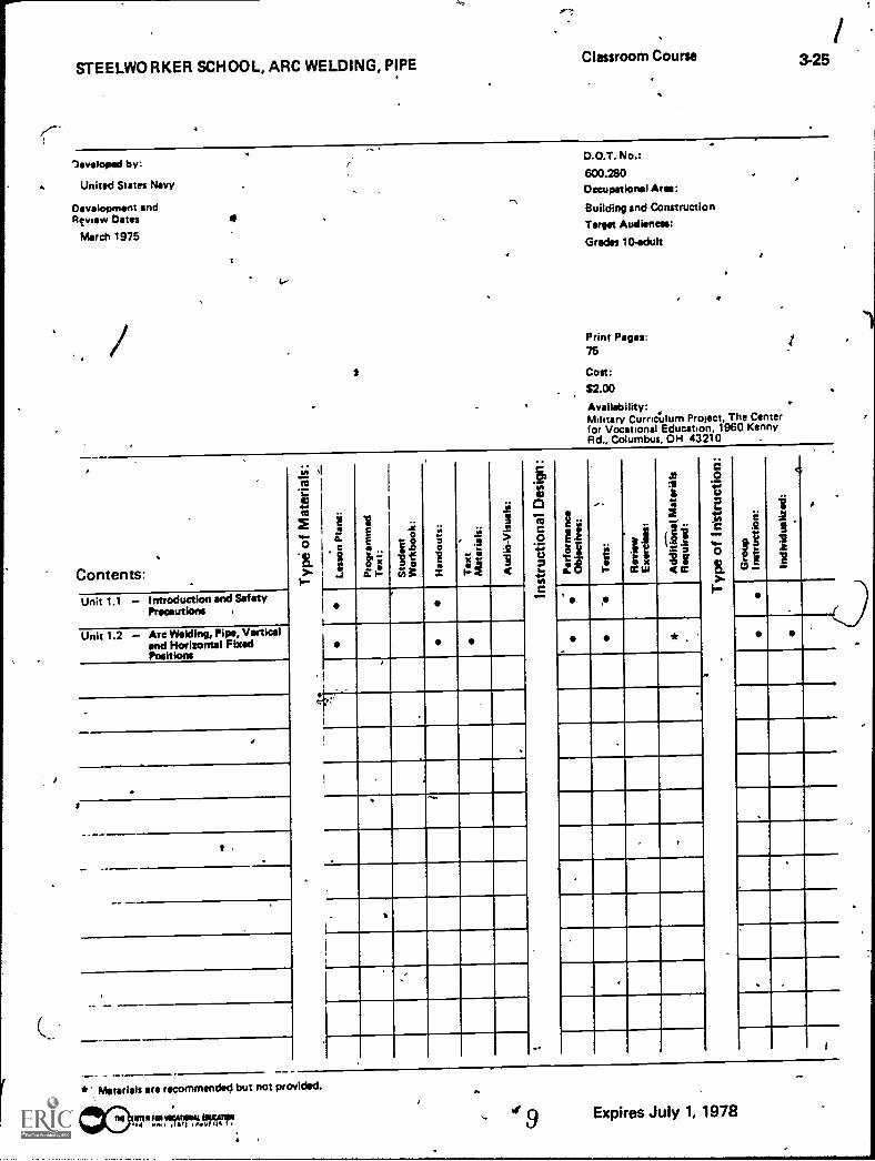
Classroom Course 3-25
STEELWORKER SCHOOL, ARC WELDING, PIPE
Table of Contents
Course Description Page 1
,Steelworker School 612.1 Arc Welding,'Pipe - Page 3
1 Instructor Guides and Supporting Material
Steelworker 3&2
Chapter 7 - Introduction to Welding Page 44
rSTEELWORKER SCHOOL, ARC WELDING, PIPE
Classroom Course 325
Developed by:
4 United States Navy
Development andRty ley/ Oates 0
March 1975
/1
,
.1,
D.O.T. No.:
600.280Occupational Area:
Building and Construction
Taraet Audiences:
Grades 10-adult
4
Print Pages:76
Cost:
$2.00
Availability:Military Curriculum Project, The Centerfor Vocational Education, 1960 KennyRd., Columbus, OH 43210 .
!
Contents:
Unit 1.1 Introduction and SafetyPrecautions ,
Unit 1.2 Arc Welding, Pipe, Vorticalend Horizontal FixedPositions
r
t .
111 i
t3 I
If
::o
ii
:2.2
.. 6; xF- 2
1.
e,
I
.44
a
s
1if81Iff .!
IleWin
to
*
c.
r
,
I
*'\ Materials are recommended but not provided.
ir.74!.tr5Trirmielepr..;
..
.. w9 Expires July 1, 1978
Course Descn non
Students com eting this short course will be able to weld 5-inch mild steel schedule 80 pipe, with backing rings, in the verticai and honzontal fixidpositions while using Mil E 7018 5/32 diameter electrodes. Some experience in arc welding is required for this course.
The course consists of two unn lessons. Part of Unit 1.1Introduction and Safety deal; with military organization and is deleted. The entire unit involvesone hour of classroom tune. Unit 1.2Arc Welding. Pipe, Vertical and Horizontal Fixed Positions is suitable for vocational education. It consists of onehour of classroom instruction and 82 hours of shop instruction.
The course contains both teacher and student materials. An instructor guide contains an introduction to the course, outline of instruction, outline of trainingobjectives, and lists of texts, references, tools, equipment, materials, training aids, training aids equipment, and the master schedule. Student job sheetsand infol-mation sheets are also prpvicied.
The text used is a Navy manual, Stodworkr 3 & 2, NAVPERS 10653.E. The required chaptxr is provided. Three additional commercoi referencesare suggested. No audio-visual materials !re suggested.
7
A
a.
vv.
larrt111-011OCA11011At MAIM.4 .. SIAI t v
VON.
;
.vek
SIA04
01140600
ON
IV4,04
1.1400
SIist
.9SStO\l,
14.14C.
tr
f
-4
(
t
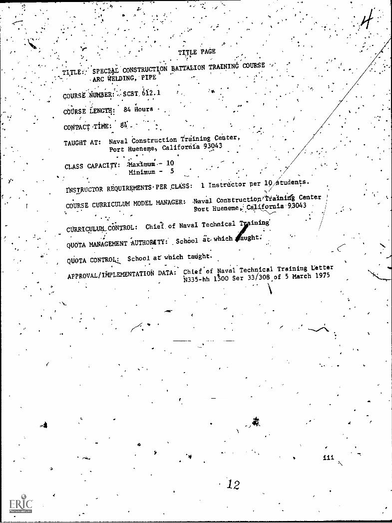
TITLE PAGE- e
,T1TLEf: SPECI4 CONSTRUCTION RATTALION TRAININd COURSE
-ARC WELDING,-PIPE
COURRilIUMBERJI:SC8T,6f2.1
,P t
el
COORSE LENGT11:. 84 iours
COWPACT-TiME: g
TAUGHT AT: Naval Construction Training Center,
Port Hueneme., Califoriia 93043 -
CLASS CAPACITY: i:1-11)Cilmm.- 10
Minimum - 5
rNSTRUCTOR RiQUIREMENTS,PER.CLSS:
COURSE CURRICULUM MODEL MANAGER:
1 Instrnctor per 10/Atudents.
Constructiop/Tiaini4 Center
Port Hueneme,'Ca4fornia'9.3043.
CORR/CULUM.CONTROL:Chiel of Naval Technical ining'
-
QUOTA MANAGEMENT'AUTHORITY: ,SchO01 at-which
aught;
QUOTA CONTROlti School at which tatight.
APPROVAL/IAPLEMENTATIOR DATA:Chief"of Naval Technical Training Letter
14335-hh 100 Ser 33/308 of 5 March 1975
4.
1 2
iii
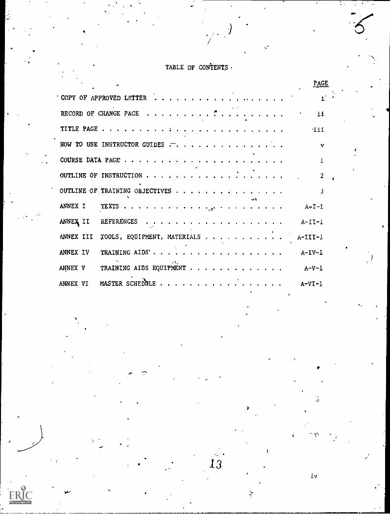
'COPY OF APPROVED LETTER
RECORD OF CHANGE PACE
TITLE PAGE
HOW TO USE INSTRUCTOR GUIDES
COURSE DATA PAGE'
TABLE OF CONTENTS
PAGE
OUTLINE OF INSTRUCTION 2
OUTLINE OF TRAINING OBJECTIVES 3
ANNEX I TEXTS
ANNEX% II REFERENCES A-II-1
ANNEX III TOOLS, EQUIPMENT, MATERIALS -% A-III-1
ANNEX IV TRAINING AIDS A-IV-1
ANNEX V TRAINING AITJS EQUIPMENT A-V-1
ANNEX VI MASTER SCHEDhLE A-VI-1
13Iv
4.
vor
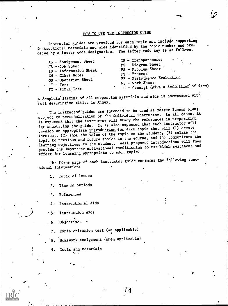
HOW TO USE THE INSTRUCTOR GUIDE
Instructor guides are provided for each topic and include supporting
instructional materials and aids identified by the topic number and pre-
ceded by a letter code designation. The letter code key is as follows:
AS - Assignment Sheet TR - Transparencies
JS.--Job Sbeet DS - Diagram Sheet
IS - Information Sheet -PS - Problem Sheet
CN - Clhss Notes PT - Pretest
OS - Operation Sheet PE - Perfot:Mance Evaluation
T - Test WS - Work Sheet
FT - Final Test G - General (give a definition of item)
A Complete listingsof all supporting materials and aids, is documented with
'full descriptive titles in.Annex.
The instructoi.guides are intended to be used as mhster lesson plani
subject to personalization by the individual instructor. In all cases, it
is expected that the instructor will study the references in preparation
for annotating the guide. It is ilso expected that each instructor will
develop an appropriate introduction for each topic that will (1) create
interest, (2) show the value of the topic to the student, (3) relate the
topic to previous and future topics in the course, and (4) communicate the
learning objectives to the student. Well prepared introductions will then
provide the important motivational conditioning to establish readiness and
effect for learning appropriate to etch topicc
The first page of each instructor guide contains the following func-
tional information:
1. Topic of lesson
2. Time in periods
3. References
4. Instructional Aids
5. Instruction Aids
6. Objectives
7. Topic. criterion test (as applicable)4
8, Homework assignment (when applicable)
9. Tools and materials
14
The pages following Page 1 of each instructor guide provide in a throw,column format the teaching/learning procedures for conducting the lesson.
The left hand column includes the outline of instructional content requiredby the objectives; the center column includes recommended instructor activ-ities or methodology; the right hand column contains recommended student
learning activities.
While the methodology and student learning activities documented ineach instructbr guide have been tested and proven to be effective forthe lead school, those schools implementing this curriculum are encouragedto exercise creativity in designing learning exercises and conceivingmettlodd and techniques to meet course objectives.
vi
15'
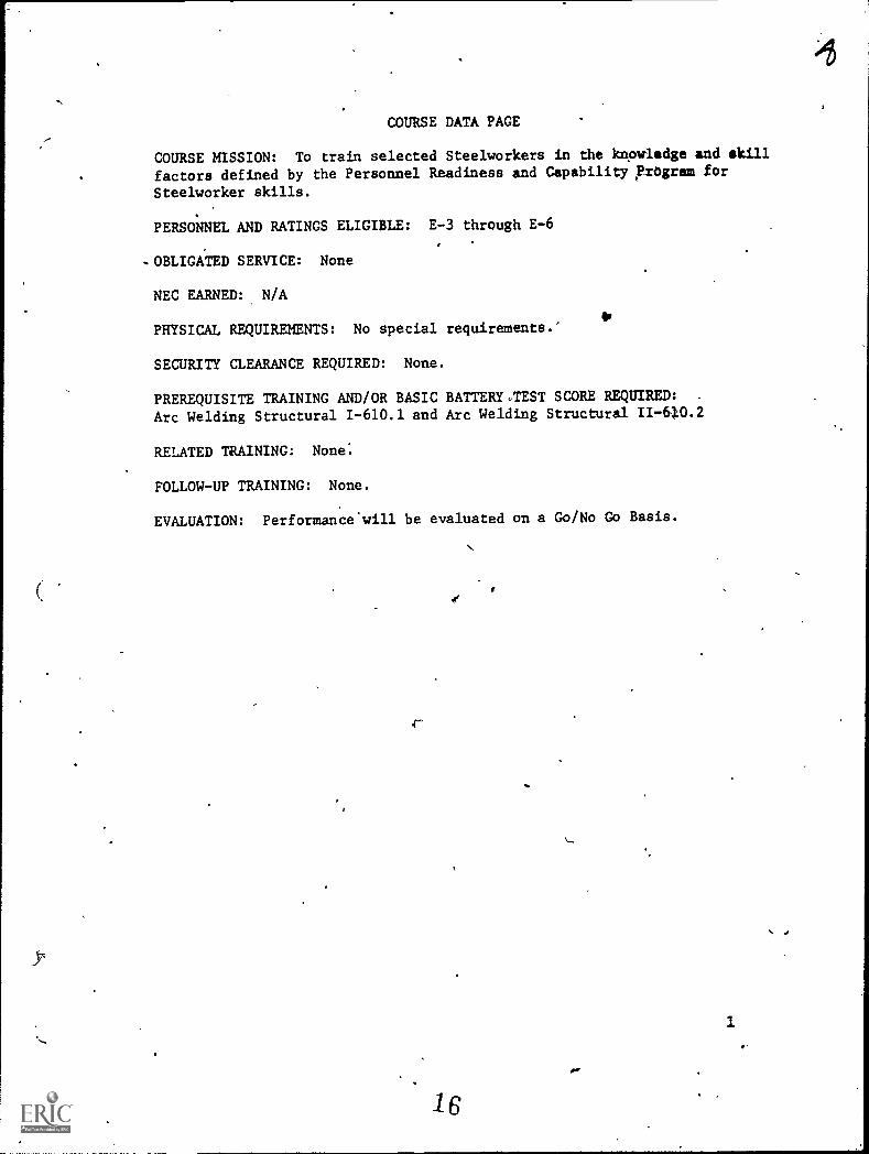
COURSE DATA PAGE
COURSE MISSION: To train selected Steelworkers in the knowledge and skill
factors defined by the Personnel Readiness and Capability ftOgram for
Steelworker skills.
PERSONNEL AND RATINGS ELIGIBLE: E -3 through E -6
-OBLIGATED SERVICE: None
NEC EARNED: N/A
PHYSICAL REQUIREMENTS: No special requirements.'
SECURITY CLEARANCE REQUIRED: None.
PREREQUISITE TRAINING AND/OR BASIC BATTERY,,TEST SCORE REQUIRED: -
Arc Welding Structural 1-610.1 and Arc Welding Structural II-610.2
RELATED TRAINING: None:
FOLLOW-UP TRAINING: None.
EVALUATION: Performance'will be evaluated on a Go/No Go Basis.
1
1 6
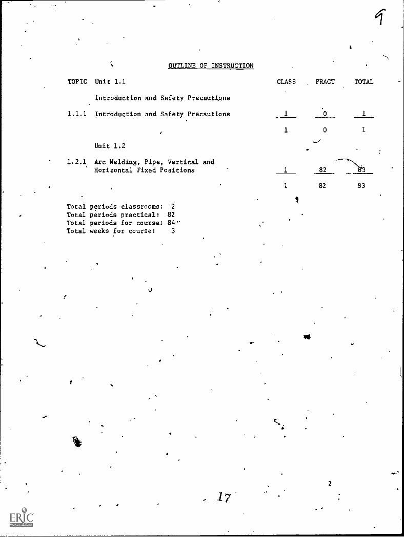
C OUTLINE OF INSTRUCTION
TOPIC Unit 1.1
Introduction and Safety Precautipna
1.1.1 Introduction and Safety Precautions
Unit 1.2
1.2.1 Arc Welding, Pipe, Vertical andHorizontal Filced Positions
Total periods classrooms: 2
Total periods practicalr 82
Total periods for course: 84-Total weeks for course: 3
'
1 ,
a
,
I
,
,
- 17
i
CLASS PRACT TOTAL
1 0
-../
1 82
1 82
,
ge
2
1
-
83
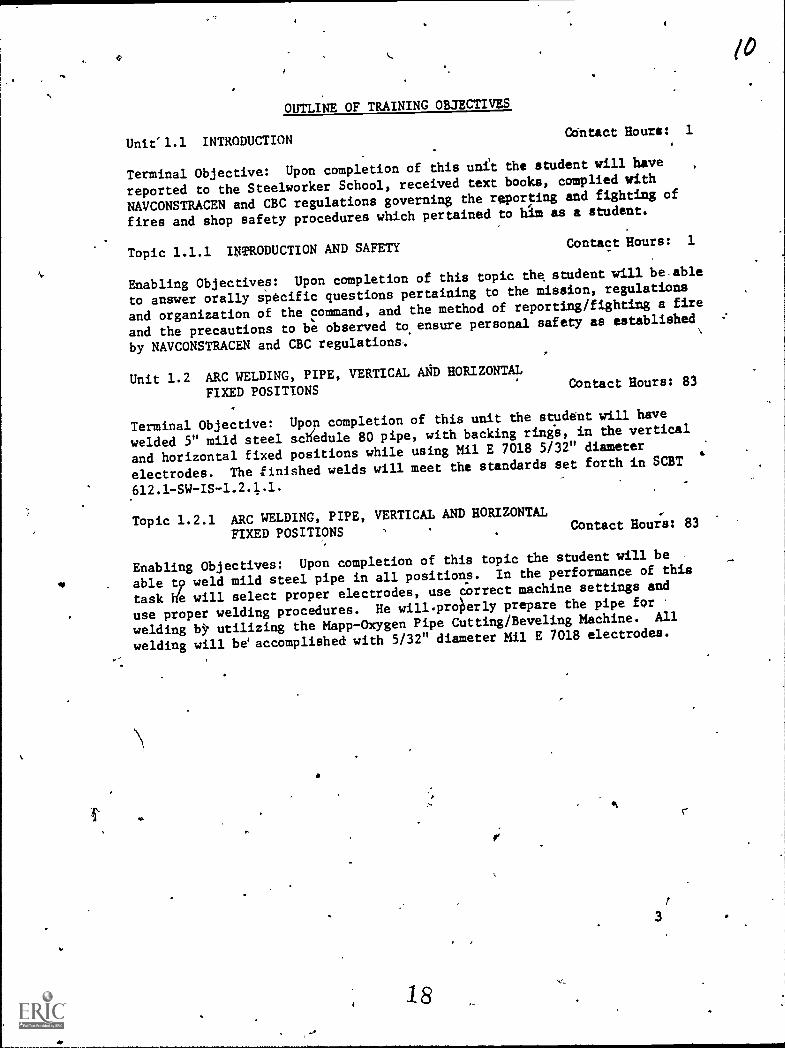
OUTLINE OF TRAINING OBJECTIVES
Unit'1.1 INTRODUCTIONContact Hours: 1
Terminal Objective: Upon completion of this unit the student will have
reported to the Steelworker School, received text books, camplied with
NAVCONSTRACEN and CBC regulations governing the repoqing sad fighting of
fires and shop safety procedures which pertained to him as a student.
Topic 1.1.1 INTRODUCTION AND SAFETY Contact Hours: 1
Enabling Objectives: Upon completion of this topic the, student will be.able
to answer orally apecific questions pertaining to the mission, regulations
and organization of the command, and the method of reporting/fighting a fire
and the precautions to be observed to ensure personal safety as established -*
by NAVCONSTRACEN and CBC regulations-.
Unit 1.2 ARC WELDING, PIPE, VERTICAL Aft HORIZONTAL
FIXED POSITIONSContact Hours: 83
-
Terminal Objective: Upon completion of this unit the studant will have
welded 5" mild steel sctfedule 80 pipe, with backing ring's, in the vertical
and horizontal fixed positions while using Mil E 7018 5/32" diameter
electrodes. The inished welds will meet the standards set forth in SCBT
Topic 1.2.1 ARC WELDING, PIPE, VERTICAL AND HORIZONTAL
FIXED POSITIONSContact Hou;s: 83
Enabling Objectives: Upon completion of this topic the student will be .
able t9 weld mild steel pipe in all positions. In the performance of this
task Ne will select proper electrodes, use correct machine settings and
use proper welding procedures. He will.prolierly prepare the pipe fcm
welding by utilizing the Mapp-Oxygen Pipe Cutting/Beveling Machine. All
welding will be' accomplished with 5/32" diameter Mil E 7018 electrodes.
r:
1 8
3
10
ANNEX
TEXTS
1. Steelworker 3 and 2 NAVPERS 10653-E.
a
ii
'fiNgu II
REFERENCES
1. American Welding Society, Standard For Qua:lificntions of Welding
Procedures and Welders For Plping and Tubing, AWS D10.9-69.
2. Operator's Manual Welding Theory and Applications T119 -237.
3. The Welding Encyclopedia, 16th Edition.
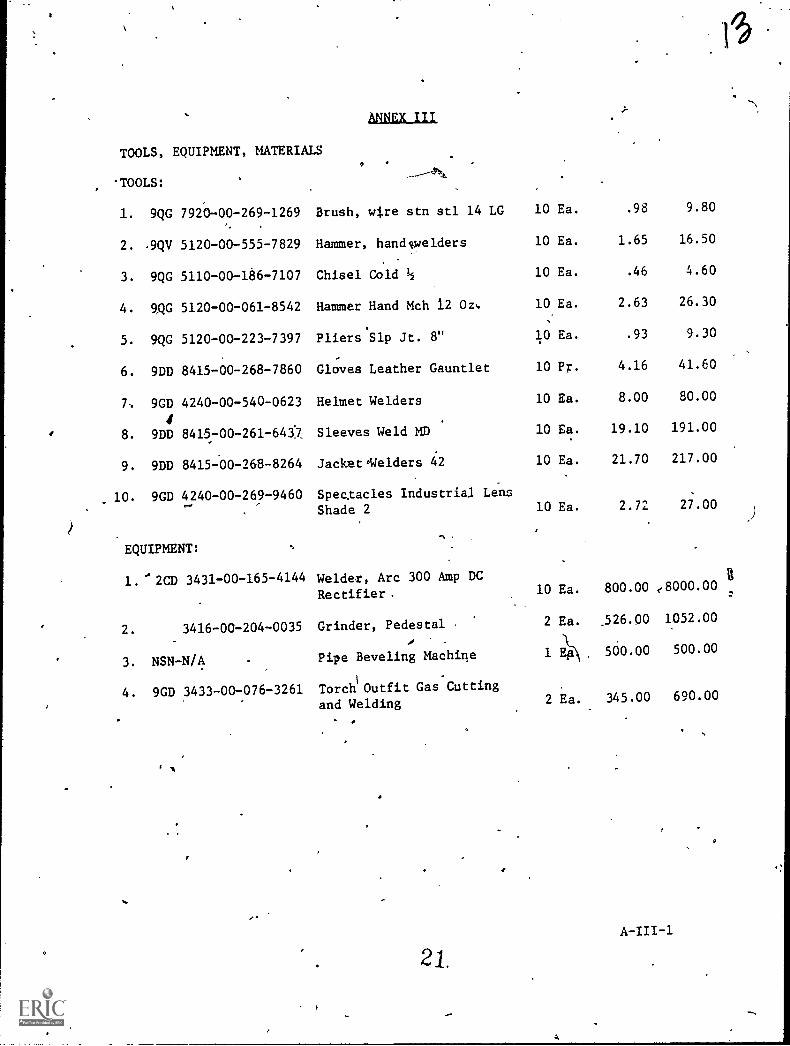
ANNEX III
TOOLS, EQUIPMENT, MATERIALS
'TOOLS:
1. 9QG 7920-00-269-1269 Brush, wire stn stl 14 LG 10 Ea. .98 9.80
2. .9QV 5120-00-555-7829 Hammer, handswelders 10 Ea. 1.65 16.50
3. 9QG 5110-00-186-7107 Chisel Cold 10 Ea. .46 4.60
4. KG 5120-00-061-8542 Hammer Hand Mch 12 Oz, 10 Ea. 2.63 26.30
5. 9QG 5120-00-223-7397 PliersSlp Jt. 8" 10 Ea. .93 9.30
6. 9DD 8415-00-268-7860 Gloves Leather Gauntlet 10 P. 4.16 41.60
7, 9GD 4240-00-540-0623 Helmet Welders 10 Ea. 8.00 80.00
8. 9DD 8415-00-261-643'7 Sleeves Weld MD 10 Ea. 19.10 191.00
9. 9DD 8415-00-268-8264 JacketWelders 42 10 Ea. 21.70 217.00
10. 9GD 4240-00-269-9460 Spec.tacles Industrial Lens
Shade 2 10 Ea. 2.72 2;.00
EQUIPMENT:
1.'2CD 3431-00-165-4144 Welder, Arc 300 Amp DC
Rectifier. 10 Ea. 800.00 e8000.00
2. 3416-00-204-0035 Grinder, Pedestal 2 Ea. .526.00 1052.00
3. NSN-N/A Pipe Beveling Machine 1 500.00 500.00
4. 9GD 3433-00-076-3261 Torch1
Outfit Gas Cutting
and Welding 2 Ea. 345.00 690.00
A
21.A-III-1
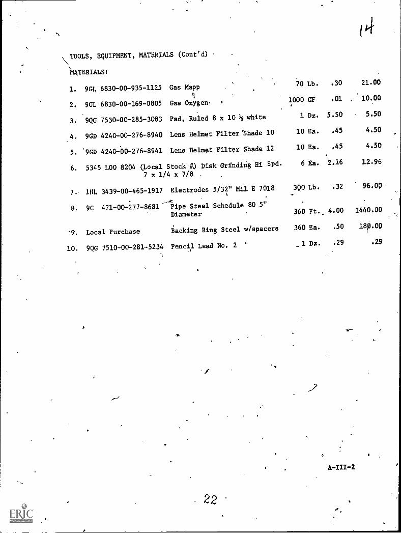
TOOLS, EQUIPMENT, MATERIALS (Coned)
14TERLALS:
1. 9GL 6830-00-935-1125 Gas Mapp70 Lb. .30 21.00
2. 9GL 6830-00-169-0805 Gas Oxygen, 1000 CF .01 10.00
3. 9QG 7530-00-285-3083 Pad, Ruled 8 x 10 ½ white 1 Dz. 5.50 5.50
4. 9GD 4240-00-276-8940 Lens Helmet Filter'Shade 10 10 Ea. .45 4.50
5. "9GD 4240-00-276-8941 Lens Helmet Filter Shade 12 10 Ea. .45 4.50
6. 5345 LOO 8204 (Local Stock 14) Disk Grinding Hi Spd. 6 Ea. 2.16 12.96
7.
7 x 1/4 x 7/8 ,
1111. 3439-00-465-1917 Electrodes 5/32" Mil E 7018 ,390 Lb. .32 96.00
8. 9C 471-00-277-8681 Pipe Steel Schedule 80 5"
Diameter 360 Ft.. 4.00 1440.00
9.. Local Purchase Backing Ring Steel w/spacers 360 Ea. .50 ap.00
10. 9QG 7510-00-281-5234 Pencil Lead No. 2 -1 Dz. .29 .29
22f
I.
.4
ANNEX IV
TRAINING AIDS:
1. Instruc,tor Prepared Materials (Local)
a. Introduction SCBT 612.1-SW-IS-1.1.1.1
b. Safety Precautions SCBT 612.1-SW-IS-1.2.1.1
c. Information Sheet, Arc Welding, Pipe SCBT 612.1-SW-IS-1.2.1.1.
d. Sample ot pipe beyeled and tack welded togethr with back-up_ling in place and showing wIld bead placement.
23
A-IV-1
S.
TRAINING AIDS EQUIPMENT:
None
4
.41110.
ANIELa
24
4
1 Co
A-V-1
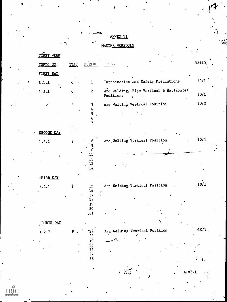
'ANNEX VI
MASTER SCHEDULE
FAST WEEK ,
.
...
.
TOPIC NO. TYPE PERIOD TITLE RATIO
FIRST DAY
r 1.1.1 C , 1 Introduction and Safety Precautiods 10/1
.1.2.1 C. 2 Arc Welding, Pipe Vertical & Horizontal
Positions . .
10/1
3 Arc Welding Vertical Position 10/2
4
5
6
7
SECOND DAY
1.2.1 P 8 Arc,Welding Vertical Position . 10/1
9
1011 .--)
12
,13
14
THIRD DAY
1.2.1 15 Arc Welding Vertical Position 10/16
17
18
19
20
,21
FOURTH DAY7
1.2.1 , 22 Arc Welding Vertical Position 10/1,
23
25
2627
28
A 47I -1 ...
OP
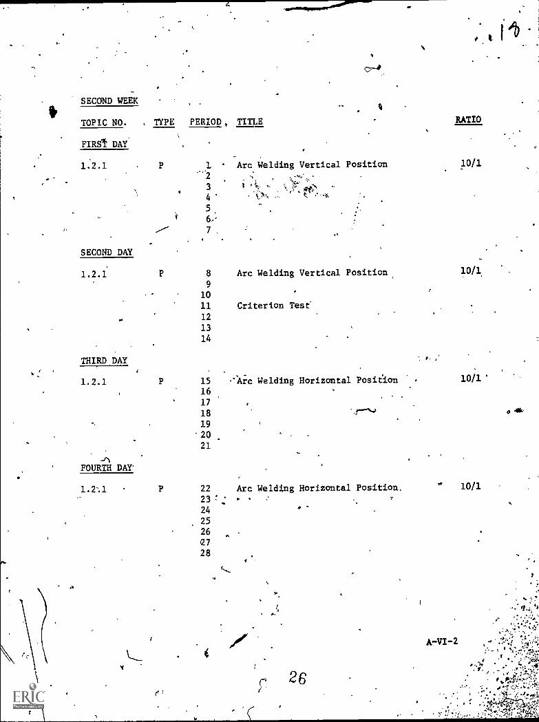
SECOND-WEEK
TYPE PERIOD, TITLE RATIOTOPIC NO.
FIRS1 DAY
P L Arc Welding Vertical Position 10/11:2.1
3
4
5
7 ,
SECOND DAY
1.2.1 P 8 Arc Welding Vertical Position, 10/1
9
10
11 Criterion Test
12
13
14
THIRD DAY
1.2.1 P 15
16
."-Arc Welding Horizontal Position 10/1
17
18 0
19
20
21
FOURTH DAY*
1.2:1 P 22 Arc Welding Horizontal Position. 10/1
23 7
24
25
26
2728
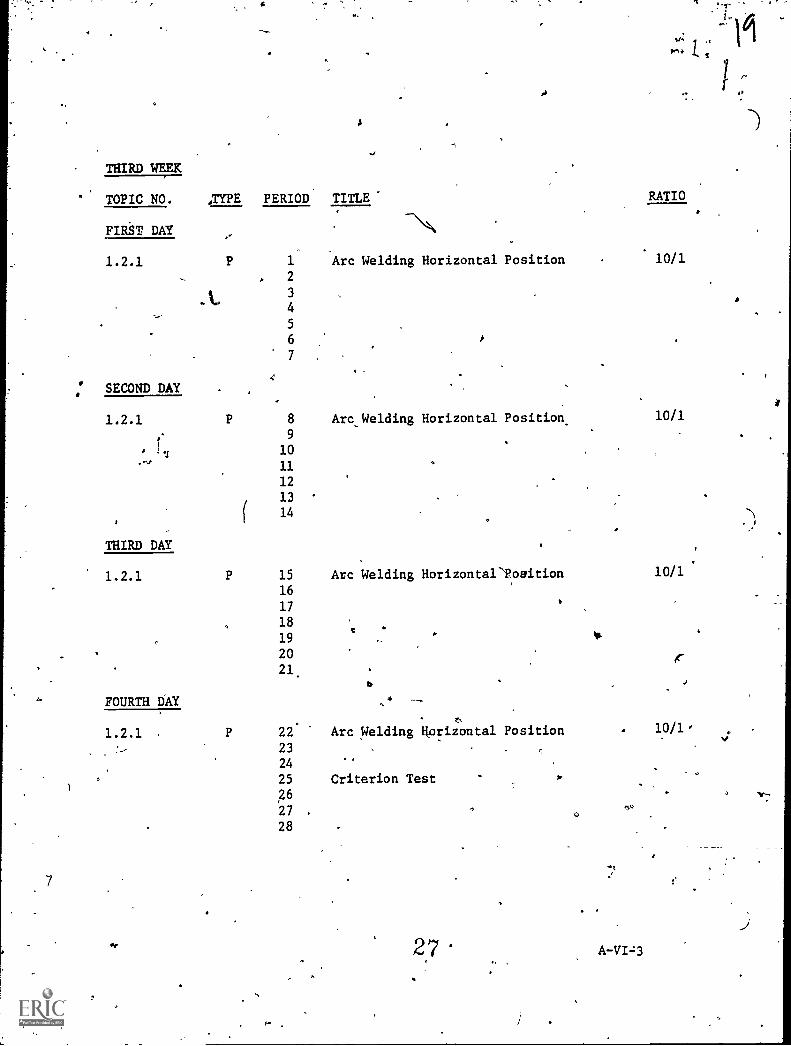
THIRD WEEK
,TYPE PERIOD* TITLE RATIOTOPIC NO.
FIRST DAY
1.2.1 P 1 Arc Welding Horizontal Position 10/1
2
3
4
5
6
7
' SECOND DAY
1.2.1 P 8 Arc Welding Horizontal Position. 10/9
, 10
11
12
13
14
THIRD DAY .
1.2.1 P 15 Arc Welding Horizontal'Foaition 10/1
16
17.
18
194
. W
' 20 r21.
FOURTH DAY
1.2.1 P 22. Arc Welding Hprizontal Position 10 / 1 -
23
24.4
25 Criterion Test P
26
27 .
28
2,7
28
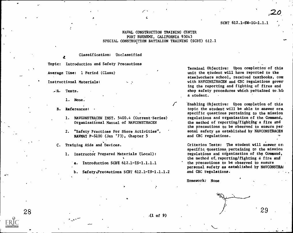
NAVAL CONSTRUCTION TRAINING CENTERPORT HUENEME, CALIFORNIA 93043
SPECIAL CONSTRUCTION BATTALION TRAINING (SCBT) 612.1
Classification: Unclassified
Topic: introduction and Safety Precautions
Average Time: 1 Period (Class)
Instructional Materials:
...A. Texts.
1. None.
B. References: -
1. NAVCONSTRACEN INST. 5400.4 (Current-Series)Organizational Manual of NAVCONSTRACEN
2. "Safety Practices For Shore Activities",
NAVMAT P-5100 (Jan '73), Chapter 5
C. Training Aids and Devices.
1. Instructor Prepared Materials (Local):
r
. Introduction SCBS612.1-IS-1.1.1.1
b. SafetytFrecautions SCBT 612.1 -IS-1.1.1.2
(1. of 9)
;20.SCBT 612.1 -SW-IG-1.1.1
Terminal Objective: Upon completion of thisunit the student will have reported to thesteelworkers school, received textbooks, comwith NAVCONSXRACEN and CBC regulations govering the reporting and fighting of fires andshop safety procedures which pertained to.hiia student. -
'Enabling Objective: Upon completion of thistopic the student will be able to answer ora.specific questions pertaining to the missionregulations and organization of the Command,the method of reporting/fightibg'a fire andthe precautions to be observed to ensure per.sonal safety as established by NAVCONSTRACENand CBC regulations.
Criterion Tests: The student will answer or;specific questions, pertaining to the missionregulations and oiganization of the Command,the method of,reporting/fighting a fire andthe precautions to be observed to ensurepersonal safety as established by NAVCONSTRAland CBC regulations.
Homework: None O.
29
fit,
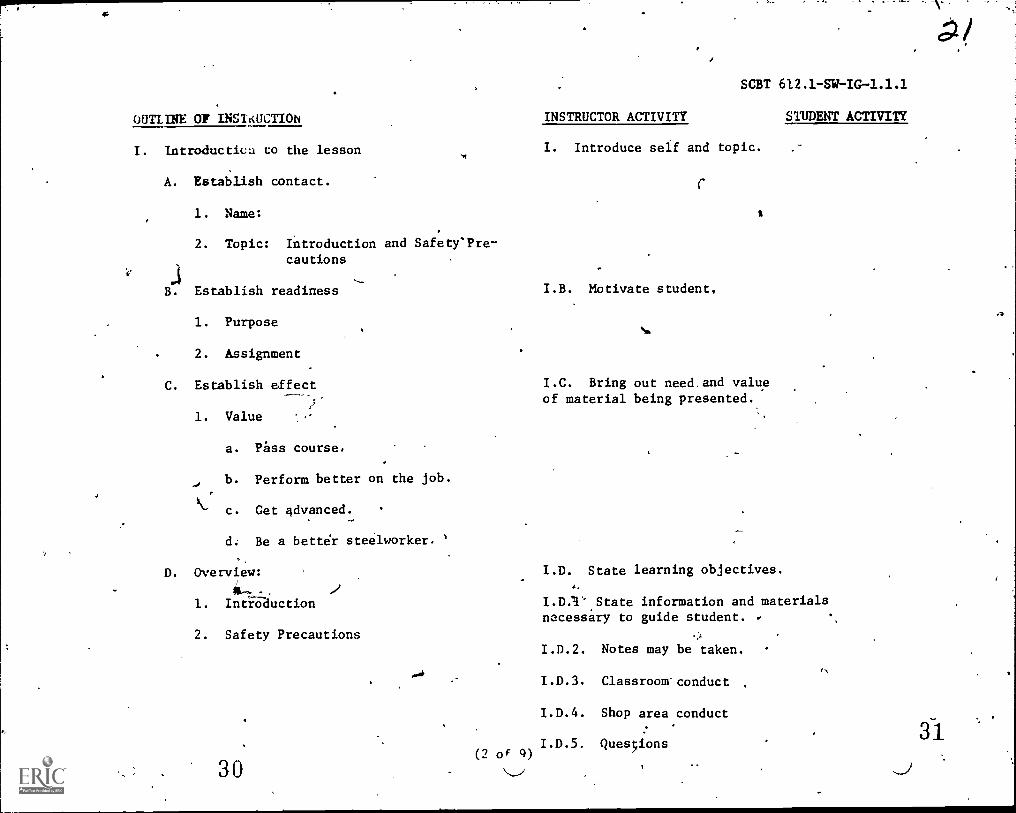
OUTLINE OF INS1KUCT1ON
I. Introductica to the lesson
A. Establish contact.
1. Name:
2. Topic: Introduction and Safety'Pre-cautions
SCBT 612.1 -SW-IG-1.1.1
INSTRUCTOR ACTIVITY STUDENT ACTIVITY
I. Introduce self and topic.
B. Establish readiness I.B. Motivate student,
1. Purpose
2. Assignment
C. Establish effect I.C. Bring out need.and value
1. Value
a. 13ss course.
b. Perform better on the job.
c. Get 4dvanced.-
d; Be a better steelworker. '
D. Overview:
1. Introduction
2. Safety Precautions
30
of material being presented.
I.D. State learning objectives.
I.D."1'.State information and materialsnecessary to guide student.
I.D.2. Notes may be taken.
I.D.3. Classroom'conduct
I.D.4. Shop area conduct
I.D.5. Quesions(2 of 9)
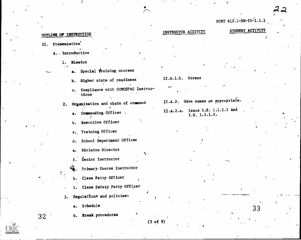
OUTLINE OF INSTRUCTION
II. Presentation'
32
A. Introduction
1. Mission
a. Special draining courses
b. Higher state of readiness
Campliance with COMCBPAC Instruc-
tions
2. Organization and chain of command
a. Commanding Officer
b. Executive Officer
c.. Training Officer
d. School Department Officer
e. Division Director
, .
f. Senior Instructor
441Primary Course Instructor
h. Class Petty Officer
i. Class Safety Petty Officer
3. Regulations and policies:
a. Schedule
b. Break procedures
(3 of 9)
INSTRUCTOR ACTIVITY
II.A.1.b. Stress
SCBT 612.1-SW-IG-4.1.1
STUDENT ACTIVITY
G4ve names as appropriate.
II.A.2.a. Issue I.S. 1.1.1.1 indI.S. 1.1.1.2.
33
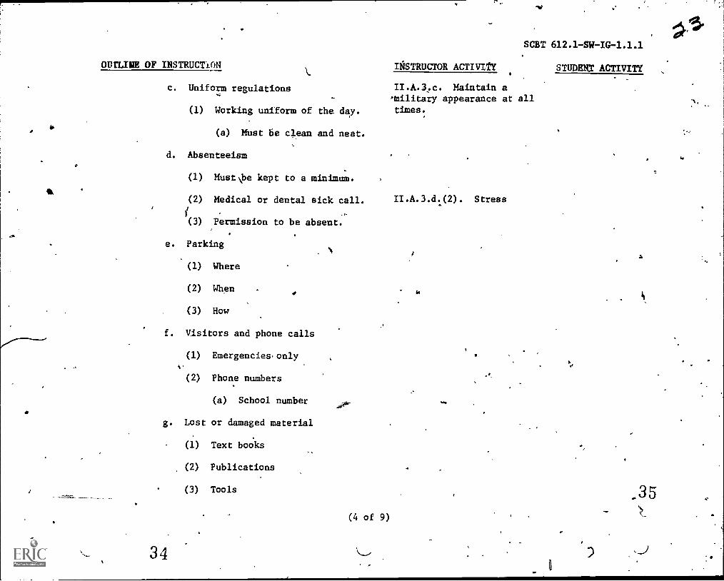
wrung OF INSTRUCTION
c. Uniform regulations
(1) Working uniform of the day.
(a) Must 6e clean and neat.
d. Absenteeism
(1) MustNbe kept to a minimum.
(2) Medical or dental sick call.
(3) Permission to be absent.
e. Parking
(1) Where
(2) When
(3) How
f. Visitors and phone calls
g
34
(1) Emergencies,only
(2) Phone numbers
(a) School number
Lost or damaged material
(1) Text books
(2) Publications
(3) Tools
-VI
SCBT 612.1 SWIG-1.1.1
IgSTRUCTOR ACTIVItY
II.A.3,c. Maintain amilitary appearance at alltimes:
(4 of 9)
II.A.3.d.(2). Stress
STUDENT ACTIVITY
_35
A
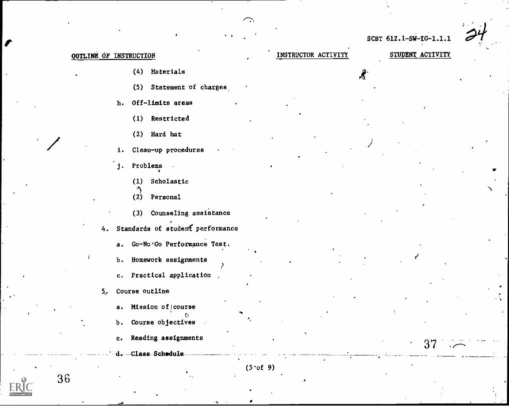
OUTLINB OF INSTRUCTION
(4) Materials
(5) Statement of charges,
h. Off-limits areas
(1) Restricted
(2) Hard hat
i. Clean-up procedures
J. Problems
(1) Scholastic
(2) Personal
(3) Counseling assi'stance
4. Standards of studeni5performance
a. Go-NorGo Performance Test.
b. Homework assignments
c. Practical application
a, Course outline
a: Mission ofIcourse
b. Course objectives ,
c. Reading assignments
Schedule
36
SCBT 612.1-SW-IG-1.1.1
INSTRUCTOR ACTIVITY STUDENT ACTIVITY
(5-of 9)
t)
37_ _
OUTLINE OF INSTRUCTION ,
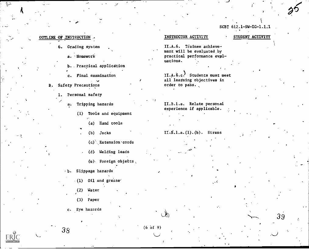
6. Grading system
a. Aomewori
b. , Practical application
c. Final examination
B. Safety Precautions
1. Personal safety
a. Tripping hazards
(1) Tools and equipmentI
(a) Hand tools
(b) Jacks
(0\,Extensioncords
(0 Welding leads
(e), Foreign objeEts
-b. Slippage hazards
(1)
(2)
(3)
Oil and gregse
Water
Paper
c. Eye hazards
38 (6 bf 9)
INSTRUCTOR ACTIVITY
SCBT 612.1 -SW -IG-1.1.1
STUDENT ACTIVITY
II.A.6. Tiainee achieve-ment will be evaluated bypractical performance eval-uations.
II.A. 6.c.1 Students must meetall learning objectives inorder to pa-ss.
II.B.1.a. Relate personalexperience if applicable.
Ii0i.l.a.(1).(b). Stress
1
40
OUTLINE OF INSTRUCTION INSTRUCTOR ACTIVITY
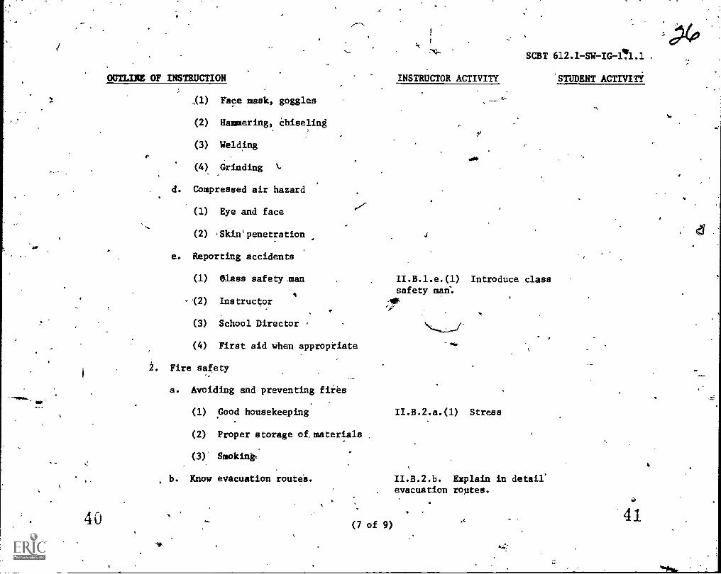
,(1) Face mask, goggles
(2) Hammering,, Chiseling
(3) Welding
(4) Grinding k.
d. Compressed air hazard
(1) Eye and face
(2) .Skin'penetration
e. Reporting accidents
(1) Class safetyman
(2) Instructor
(3) School Director .
(4) First aid when appropriate
2. Fire safety
a. Avoiding and preventing fiies
(1) Good housekeeping
(2) Proper storage of,materials
SCBT 612.1 -SW-IG-1,1.1
STUDENT ACTIVITY
II.B.l.e.(l) Introduce classsafety man:
II.B.2.a.(l) Stress
(3)' Smoking;
b. Know evacuation route's. II.B.2.b. Explain in detail'. evacuation routes.
(7 of 9)41
OUTLINE,OF INSTRUCTION
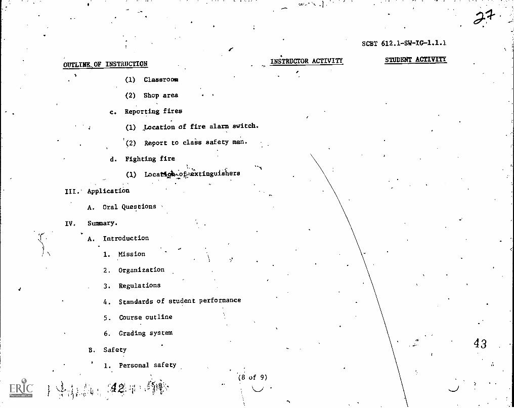
(1) Classroom
(2) Shop area
c. Reporting fires
(1) ,pocation of fire alarm switCh.
P(2) Report to clais safety
d. Fighting fire
(i) Locat1064: t4Xtinguiihers
III. Application
A. Oral Questions
IV. Summary.
A. Introduction
1. Mission
2. Organization
3. Regulations
4. Standards of student performance
5. Course outline
6. Grading system
B. Safety
SCBT 612.1-SW-IG-1.1.1
INSTRUCTOR ACTIVITY STUDENT ACTIVITY
1. Personal safety
4 3

.0 .
OUTLINE OF INSTRUCTION
2. Fire safety
V. Test.
A. None
VI. Homework
-
44
0A. None
,
,
v
.%
-
`1
(9 of 9)
-
0
INSTRUCTOR ACTIVITY
`It
..,
SCBT 612.1SW-IO-1.1.1
STUDENT ACTIVITY
&
-
1
- 45
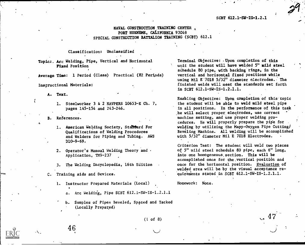
NAVAL CONSTRUCTION TRAINING CENTER f,
PORT HUENEME, CALIFORNIA 93048SPECIAL CONSTRUCTION BATTALION TRAINING (SCBT) 612.1
Classification: Unclassified
Topic:. Arc Welding, Pipe, Vertical and Horizontal
Fixed Position
Average Time: 1 Period (Class) Practical (82 Periods)
Inspructional Materials:
A. Text.
1. Steelworker 3 & 2 NAVPERS 10651-E Ch. 7,pages 145-154 and 243-246.
B. References.
1. American Welding Society, Stalliturd ForQualifications of Welding Proceduresand Welders for Piping and.Tubing. AWS
D10-9-69.
2. Operator's Manual Welding Theory andApplication, TM9-237
3. The Welding Encyclopedia, 16th Edition
C. Training aids and Devices.
1. Instructor Prepared Materials (Local)
a. Arc Weldirig, Pipe SCBT 612.1-SW-IS-1.2.1.1
b. Samples of Pipes Beveled, Spaced and Tacked(Locally Prepared)
(1 of 8)
4 6
SCBT 612.1-SW-IG-1.2.1
Terminal Objective: .Upon completion of thisunit the student will have welded 5" mild steelsChedule 80 pipe, with backing rings, in thevertical and horizontal fixed positions whileusing Mil E'7018 5/32" diameter electrodes. Thefinished welds will meet the standards set forthin SCBT 612.1-SW-IS-1.2.1.1.
Enabling Objective: Upon completion of this'topicthe student will be able to weld mild steel pipein all positions. In the performance of this taskhe will select proper electrodes, use correctmachine setting; and use proper welding pro-cedures. He will properly prepare the pipe forwelding by utilizing the Mapp-Oxygen Pipe Cutting/Beveling Machine. All welding will be accomplishedwith 5/32" diameter Mil t 7018 Electrodes. .
Criterion Test: The student will weld two piecesof 5" mild steel schedule 80 pipe, each 6" long,into one homogeneous.section. This will be
accomplished once for the.vertical-positi6n andonce for the horizontal position. Evaluation ofwelded area will be by the visual acceptance re-'quireMents stated in SCBT 612.1-SW-IS-1.2.1.1.
Homework: NOne.
N.ks, 4 7
_1
1
c. Samples of pipes showing bead placement,(Locally prePared).
d. X-Rays showing defects in welds and good welds,(Locally prepared).
D. Tools:
1. Chipping hammer
2. Chisel
3. Homier*, ball peen
4. Pliers, 8"
5. Gloves
6: Hood, arc
'7. Sleeves
8? Jacket
9. Spat'
10. Flash goggles
E. Eguipment:
1. Oxy-mapp cutting and welding unit.
.2. Electric arc welding unit:
3. Portable sander
4. Bench grinder
48(2 of 8)
SCBT 612.1 -SW-IG-1.2.4
V.
49
5. Pipe beveling machine.
F. Material .
1. Pipe, mild steel 5" schedule 80
2. Oxygen
3. Mapp gas.
4. Sanding disc
5. Backing rings w/spacers
-(3 of 8)
°
SCBT 812.1-SW-1G-1.2.1
or
51
SCiT 61 .2.1 :
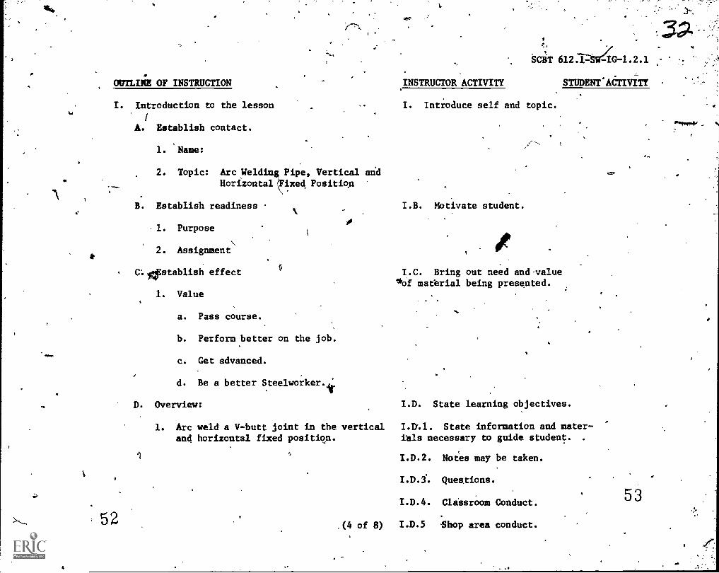
OUTLINE OF INSTRUCTION .INSTRUCTOR ACTIVITY STUDENT'AeTIVITY
I. Introduction to the lesson
A. Establish contact.
52
1. 'Name:
I. Introduce self and topic.
2. Topic: Arc Welding Pipe, Vertical andHorizontal Fixed Position
B. Establish readiness I.B. Motivate student.
1. Purpose
2. Assignment
C:Apstablish effect
1. Value
a. Pass course.
b. Perform better on the job.
c. Get advanced.
I.C. Bring out need and.valueloof material being presented.
d. Be a better Steelworker.i
D. Overview: I.D. State learning objectives.
1. Arc weld a V-butt joint in the vertical State information and meter-
and horizontal fixed position. ials necessary to guide student.
.(4 of 8)
I.D.2. Notes may be taken.
Ques.tions.
I.D.4. ClaesrOom Conduct.
I.D.5 Shop area conduct.
53
"41,944.40
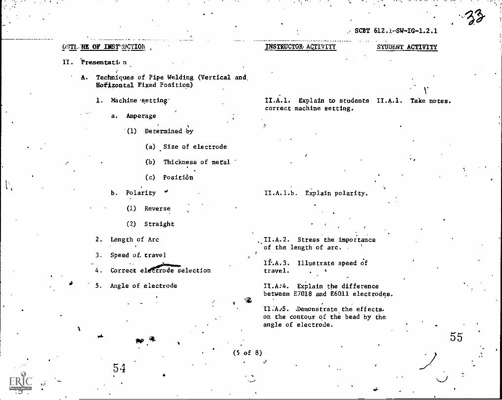
WITI.AfE OF INSVJLICTION INSTRUCTOR. ACTIVITY
I/. .Presentati,n
A. Techniques of Pipe Welding (Vertical and,Hofizontal Fixed Positio.n)
1. Machinelkettina'
a. Amperage
"(1) Thetermined by
(a) ..Size of electrode
(b) Thickness of metal
(c) Position
b. Polarity
SCBT 612J-SW-IG-1.2.1
STUDENT ACTIVITY
VII.A.1. Explain to students 11.4.1. Take notes.correct machine setting.
II.A.1.b. Explain polarity.
(1) Reverse
(2) Straight
2. Length of Arc Stress the importanceof the length of arc. '
3. Speed of. travel
Illustrate speed Of4. Correct eldennelection travel.
5. Angle of electrode II.A:4. Explain the difference
5 4
9
(5 of 8)
between E7018 and E6011 electrodes.
.Demonstrate,the effects .
on the contour of the bead by theangle of electrode. ft
OUTLINE OF INSTRUCTION
56
SCBT 612.1-SW-IG-1.2 1
INSTRUCTOR ACTIVITY-- '---STUDENT-ACTIVI
B. Stress-relieving and cleaning of pipe II.B. Stress the importanceof removing all slag.
1. Peening to relieve stress
2. Degree of cleaning
C. Preparation of pipe prior to welding
1. Beveling
a. By manufacture
(1) Premachined by manufacture
b. In the field
(1) Beveled by pipe beveling machine
(2) Beveled by hand torch
2. Cleaning
a. Clean off all mill scale and slag
3. Aligning
a. Very important because one bevelwill not melt evenly with the other.
4. Spacing
a. Predetermined by spacing stubs onbacking rings.
5., Tacking
a. Size and number
(6 of 8)
II.C.5. Stress the importanceof proper tacking of pipe.
57
5,(1-
OUTLERE OF INSTRUCTION
(1) Small tacks
(2) Four tacks
DO NOT PLACE 2ACKS WHERE YOU PLAN TO STARTOR STOP WELDING.
NOTE:
D. Faults in arc welding.
14 Porosity
2. Undercut
3. Overlap
4. Poor fusion
5. Incomplete penetration
6. Spatter
7. Warpage
III. Application
A. Practice welding in the shop.
IV. Summary
A. Techniques of pipe-welding (vertical &horizontal).
B. Stress relieving and cleaning pipe
C. Preparation of pipe prior to welding
D. Faults in arc weldi
58(7 of q)
SCBT 612.1-SW-IG-1.2.1
INSTRUCTOR ACTIVITY
II.D. Explain reasons forfaults in welding.
II.D.a. Stress the impor-tance of neatness.
IIALb. For testing, a com-pleted test piece can only beevaluated.
II.D.c. Have test pipe cut,beveled and letter stampedprior to practical test time.
STUDENT ACTIVITY
II.D. Make singlevertical and horizofixed pipe welds f.uation.
II.D.d. Stress that pipe willnot be turned for weldingduring test.
III.A. Observe studentsduring welding to help over-come difficulties.
7r-
-butttal
eval-
Prac ce under super-vision
59
OUTLINE or INSTRUCTION
V. Test
A. Criterion test will be based on the students+ability to iltssethe visusl standards as setforth in SCBT 612.1 -SW -IS-1.2.1.1
VI. Assignment: Read Pages 145-154 and 243-246Steelworker 3 6 2 NAVPERS 10653-E.
(8 of 8)
SCBT 612.1 -SW-IC-1.2.1
INSTRUCTOR ACTIVITY STUDENT AlaiviTY
:
1
INTRODUCTION
I. Organization and Chain of Command
a. Commanding Officer
b. Executive Officer
SCBT 612.1-SW-1S-1.1.1.1
SPECIAL CONSTRUCTION BATTALION TRAININGNAVAL CONSTRUCTION TRAINING CENTER
PORT HUENEME, CALIFORNIA 93043
INFORMATION SHEET
c. Training Officer
d. School Department Officer
e. Division Dire4gr
f. Senior Instructor
g. Primary Course Instiuctor
h. Class Petty Officer
i. Class Safety Petty Officer
2. Schedule
a. Classes will convene at 0730 and cantinue until 1600.
b. Five-minute breaks beween each class and one hour for lunch.
3. Uniform regulations
a. Working uniform of the day
b. Must be clean and neat.4
4. Absenteeism
a. MUst be kept to a minimum.
(1) One complete day iS grounds fOr dismissal.
(1 of 2)
_2 .
5. Parking
gCBT 612.1 -SW-IS -1.1.1.1 .
a. As directed by the instructor.MC,
6. 'Visitors and phone calls
a. Emergencies only
(1) School ext.
7. Lost or damaged material
a.. Students will be accountable for all books, tools and special
equipment when issued to them.
8. Off-limits areas
'A. Set by the instructor.
9. Clean-up procedures
a. Daily clean-lip every eVening.
(1) Areas designated by the instructor.'.
(2) Senior Class Petty Officer is responsible.
b. Field day held on Fridays.
(1) Area designated by the instructor.
(2) 'Senior Class Petty Officer is responsible.
10. Problems
a. Chain of Command will be ntilized
b.. Major problems will be referred to the student's command.
11. Grading system
a. Emphasis will.be placed on the practical application rather than
knowledge.
r (2 of 2)
63
SCBT
SPECIAL CONSTRUCTION BATTALION TRAININGNAVAL CONSTRUCTION TRAINING CENTER
INFORMATION SHEET
SAFETY PRECAUTIONS
INTRODUCTION: This information sheet.is designed to provide informationon safety precautions and proper actions in case of fire.
SUBJECT MATTER:,
1. Alcoholic liquors or narcotics shall not be transported to the schoolor working area, and no nian shall go to work while under the influence ofliquor or narcotics.:
2. Fighting, wrestling, or throwing of o6jects and hoseplay is positivelyprohibited.
3. Strict attention to duty,is the first requirement of safety. You arewarned against permitting your attention to be distracted from your work,asthis is the cause of many injuries. "Keep your mind on your work and safety
on your mind."
4. Do not talk to or distract the attention of machine and-equipment opera-,tors while the machines or equipment is in operation.
....... .
5. Obey warning signs and tags. Their purpose is to point out.hazards. To
disregard them is to deliberately invite injury.4
6. No one-ts permitted to ride on fenders, running boards, or bus steps;nor tp ride standing on truck bodies.
7. Employees riding on trucks or other vehicles must keep arms and legsinside the body of the vehicle at all times. Sitting on side boards is
prohibited.
8. No one is permit.ted to get on or off a moving vehicle.
9. Never try to operate any equipment unless you are familiar with itsoperation and have been atAhorized to do so. 0
10. Report to your supervisor any defects in equipment or any other con-.-,dition which might cause.an accident.
.400'
11. Remember that at all times some of your co-workers on.the job areinexperienced and may not know where danger exists. Warn any man when
danger is near. He may know all about it; if 4o no harm is done.
12. Be constantly aware and stay clear of moving equipment and material
(1 of 3)
64t-
f
4,07SCBT
13. You are in Unger when you are in a position between a moving piece
of equipment or load of materiel and a stationary object.
14. Do not use a box, chair, barrel, or other makeshift in Place of a
ladder.
15. Leaning tools or materials against walls,unsafe practice.
16. Cleaning, oiling, repairing, or adjustingwhile it is In motion may cause serious injury
--cidlumns, or machines ii anA-7=144
rmachiraiy or equipmentand la prohibited.
17. Always use all safeguards provided. See that all guards or other
protective devices are in place before beginning work.
18. Any extensiotlamp, power tool, welding cable, etc. with frayedinsulation, loose connection, or damaged plug should be repaired or
replaced immediately.
19. Do not touch, handle or tamper with any electrical equipment, air,
water, gas, oil, or steam line, or machinery which does not come within
your regular duties unless you have received permission and instructions
from your supervisor.
20. Do not throw any switch, turn any air, water, steam or oil vall:re, or
start any machine without first makIng certain that everything is in the
clear and that no worker will be injured by such action.
21. In doing work entailing possible eye injury, protect the eyes by wearing
the proper type of safety goggles provided for this purpose.
22. Every precaution.must be taken to prevent fires. Rxtinguish
lighted matches, cigarettes or cigars before throwing them away.
23. Throw waste paper, oily rags, aid other refuse in containers provided
for that purpose.
24. Keep aisles, stairways, exits, and fire equipment clear of obstruction
at all times.
25. In case of fire turn in the alarm and return to the scene of the fire'
to help in extinguishing it.
26. The following are rules to be observed while in the welding shop area.
YOU WILL:
a. observe all safety rules.
b. at all times wear flash goggles in the arc shop.
(2 of 3)
6 5
,*4
-)SCBT 612.1-SW-1S-1.1.1.2
c. Wear cutting $oggles when using cutting torches.
d. Wear face shields while grinding.
e. Wear glovei when welding or cutting.
f. Wear welding leathers at all times in arc shop.
g. Use pliers to pick up hot metal.
h. Keep_curtains closed on welding bOoths.
i. Make complete use of welding electrodet_\
j. Use only materials designated by the instructor.
k. Clean your welding booth and area.
1. Replace oxy-acetylene bottles when found empty.
m. Take breaks on east end of building.
YOU WILL NOT:
-)unless directed to by instructor.n. Use grinders or buffers
Waste materials.o.
p. Weld on face-of pl es. .
q. Throw electode tubs on the deck.
r. Pick up hot metal with gloves.-
s. Use flash goggles when cutting.p
t. Weld anything othek than that designated 1;y instructor.
u. Play or fool in s or with another man's tools and equipment.
v. Enter toolroam unless directed*to do so by instructo(.
w. Bring any type food or beverages into the shops.
x. Go to the exchange gedunk truck.'
y. Leave thearea without instructors Approval.
,
SCBT
NAVAL CONSTRUCTION TRAINING CENTERPORT HUENEME, CALIFORNIA 93043.
. ARC WELDING, PIPE
.INFORMATIONSHEET
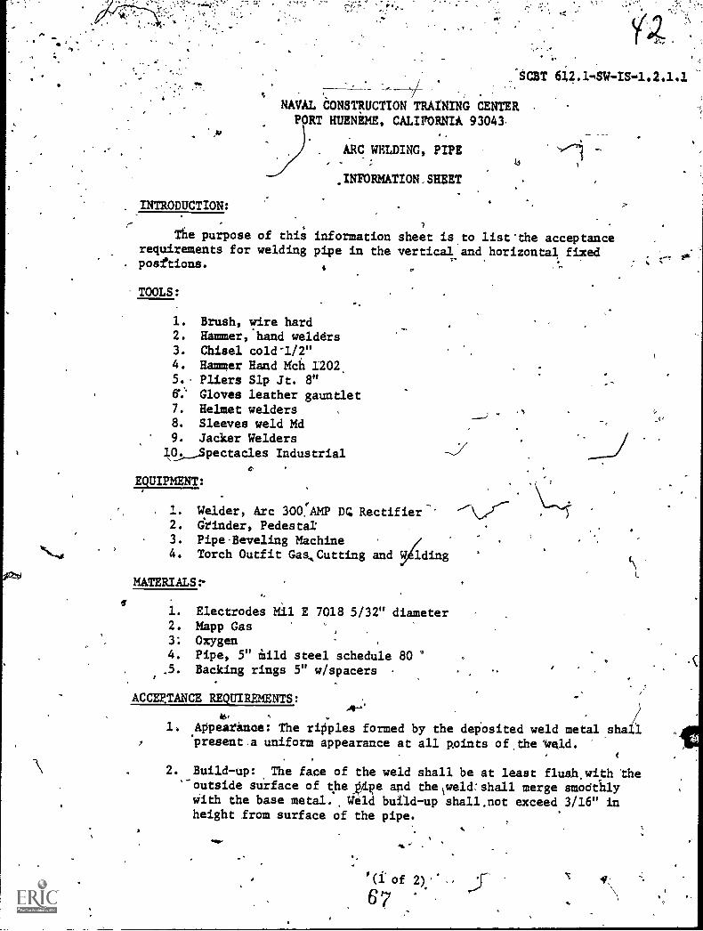
./NTRODUCTION:
r .. 1
Tile purpose of this information sheet is to list'the acceptancerequirements for welding pipe in the vertical and horizontal fixed
,posttions.s , .'
TOOLS:
1. Brush, wire hard2. Hammer,'hand welders3. Chisel cold-1/2"4. Hammer Hand Mch 1202,5.. Pliers Slp Jt. 8"6. Gloves leather gauntlet7. Helmet welders8. Sleeves weld Md9. Jacker Welders19,Spectacles Industrial
EQUIPMENT:
1 Welder, Arc 300!AMP Da Rectifier'.2. drinder, Pedestal:3. Pipe-Beveling Machine4. Torch Outfit Gaa,Cutting and 34.ding
MATERIALS:-0/
1. Electrodes Mil E 7018 5/32" diameter2. Mapp Gas3; Oxygen4. Pipe, 5" thild steel schedule 80.5. Backing rings 5" w/spacers
N
ACCEPTANCE REQUIREMENTS:
1. Appearanae: The ripples formed by the deposited weld metal shall
AW'
I 'present a uniform appearaace at all paints of the Veld.
2. Build-up: The face of the weld shall be at least flush,with the'outside surface of the p',fi.pe and thelweld:shall merge smoatillyWith the base metal,. Weld build-up shall,not exceed 3/16" inheight fram surface of the pipe.
,
4!,
a
_
iNFORRATION SHEET (Cont'd)
C.
3. Weld Width:. The width of 'ihe finished weld shall not exceed15/16";
lc. -Undercut: The weld shall not have, gore than 1" total.length
of undercut and no undercut'ahall exceed 1/16" in depth.
Overlap: The weld shall not have more than 1" total lengthof overlap.
6. Cracks: There shall be no cracks in the welded'joint.
A
o'
68
(2.of 2)
CHA
INTRODUCTIO
e I
While vaftous methods are used for Joining/metals, welding 16 one of the urst convenient!and rapid methods:v:4'9113131e. In the naval serv-1ice, as well as in privatekIndustry, welding andits allied processes are widely used by metalworkers in the fabrication, maintenance, andrepair of parts and structurea ranging froincheir legs to atomic reactors,
Welding,- the same as ana of the selledadtrades,is bro in scope. Yoe cannot ome
a weldor simply by reading i book, YoG. ,willneed prietice and experience, as well is pa-tience. There is a lot to be gained, however,through study. For instance, by learning thecorrect method or procedure for doing ajobfioma book you may eliminate .mady unnecessaryerrors which otherwise would oeeur throtrghtriel and error. .
M an introduction to the subject of welding,this discussion is designed-141 equip you witha background-of baste information applicable toweldifig in general. Variod's topibt covered in-clude types of welded joints; welding positions,welding sequences, methods of e'ontrolling ex-pansion and' contraction in me41 during weld-ing, welded joint desigd, 'aid welding difficultieslikely to be encountered by the inexperiencedweldor. Special attention also 1sgiven to safety, .
the purpose being to brief you on protectiveclothing and other device, such as weldinggoggles and helmets, designed for your personalprotection. -Throughout the discussion varioustechnical terms peculiar to the, welding tradeare used, and care hat been taken to explainthe meaning of terms that might be .new to thebeginner.
WELDING PROCESSES ANDMATERIALS
, The term WELDING. 'PROCESS refers to ametat-jointng process wherein coalescence isproduced by heating to suitaqle temperatures;
TER7
TO WELDING
with or without the application of pressure orby the application of pressure "alone, and withor without the use of filler metal. COAL ESC ENC Emeans the growing _together, or growth into onebody, of the base metal parts. A muter chartof welding processes is shown -in figure 7-1.
Welding processes obviously have differenceswhich distinguish one from another. However,all welding processes are based upon the prin-ciple of applying or generating HEAT at thejoint and langing the surfaces into INTIMATECONTACT'SO that the joining surfaces will coa-lesce. Although coalescence of the Joining sur-faces is the goal of all welckng processes, thisgoal is achieved in different ways.
With respect to HEAT, the welding processesdiffer as to the source of heat, the manner inwhich heat is applied or generated, and theintensity of the heat. The source of heat maybe the cumbustion of a fuel gas such as ackety-iene in otimbination with oxygen; and electric arc;en electric, gas, or oil furnace; the resistanceof metal to the -flow of electric current; or achemicia reaction between a metal oxide andfinely ,divieed aluminum.
The. weldi:pro-cesses most cominonly usedby Navy Sieelworkers involve the combustion ofa fuel gas. as in oxyacetylene welding and torchbrazing; and the use of an electric arc, as inmetal-arc welding. ,t
The intensity of heat applied or generatedat the Joint uries according to the metals, beingjoined and according to the welding process beingused. All welding orocesses except brazingutilizetemperatures high enough to melt the base metal;brazing is the ONLY welding process in whichthe melting of the base metal is not necessaryfor coalescence to occur. Brazing is, therefore,similar to- soldering (not considered 'a weldingprocess), except that higher temperature's areused for brazing.
1146 9

Chapter 7INTReOI5UCTION TOWEL6ING
R11.34Xl'igure 7-1. Master ciiart,of welding processes.
The 'term BRAZING refers to a group ofwelding processes wherein coalescence is pro-duded by heating to a suitable temperature apdby using a filler metal having a liquidus aboveo800 F (427* C), and below the solidus of the basemetals. The filler metal is distributed betvieen
the closely fitted surfaces of the joint by capillaryattraction.
For clarity note that LIQUIDUS mealks thelowest temperature at which a metal or analloy is completely liquid; and SOLIDUS means
40,
STEELWORKER 3 tz 2
tie highest temperature at w,h a metal' oralloy is completely solid. -
The term SOLDERING refers to a group ofj4ining processes wherein coalescence is pro-ducad by heating to a suitable temperature andby using a filler metal haying a liquidus notexceeding 800 F (427 C) and below the solidusoi tlie base metals.
OXYACETYLENE AND ELECTRIC-ARCWELDING
, Since oxyacetylene and electric-arc weldingare the processes you will be concerned withprimarily at your present level, let us notea few of the similarities and differences in thetim processes.
A main difference between the two processesii in the source of heat used. In the oxyacety-lene process, heat is produced by burning acety-lene gas mixed with oxygen, discharged derpressure from a torch designed for that purp e.
The heat source for electric-arc Iveldi isprovided by motor-generated sets, transformers,or rectifiera. This process employs carbon ormetal electrodes. The carbon arc is sometimes..used for metal cutting.
The two processes are similar in that theintimacy of contact required for coalescenceis attaineci without pressure. The joint in eitherprocess ill made by melting the edges of thebase metal with a suitible degree of heat tindintroducing a filler'metal into the molten puddle.They *tee 'similar also in the phases leading upto the actual joining operation such as cleaning,joint design, selection of filler metal, preheating,--the control of expansion, contraction, and internalstresses, and determining the sewence of fillermetal deposition. They are dissimilar in that thetemperature 'developed by the electric arc isconsiderably higher than that prodliced by the,, xv ac stylene Eame. .
In electric-arc welding, the heat is con-centrated over a relatively small area, whilethe heat of the oxyacetylene flame spreads overot large area. Heayconcentration is a distinctadvantage .f.or marlf applications because less heatspread reduces buckling or warping, increasesthe depth of heat penetration, and speeds up thewelding operation.
FLUXES
The welding or brazing of. most metals re-wires tlie, use of a. flux to produce a soundJoint. The term FLUX refers to material used
fSailitate the removalof oxides and other undesirable substances inwelding. Fluxes serve to bring the filler metalinto intimate contact with the metals beingjoined.Fluxes act as cleaning agents in that they diss-solve oxides, release .trapped gases and srag,and cleanse metals for welding, soldering andbrazing.
Fluxes are available in paste, powedered, andliquid form. Powders can be sprinkled on thebase metal, or the filler rod can be heated anddipped into the powder. Liquid and paste fluxesmay be applied to the filler rod and to thebase metal with a brush.
In electric-arc welding _the flux is on theelectrode in the form of a cellulose or mineralencasement around a wire core.
In the welding of alloyed metals, the useof a flux is necessary.. This is because theoxides of most alloys have higher melting pointsthan the metals themselves, and remain solidwhen the filler metal has become fluid. As solids,they interfere with the proper disposal of tilemolten filler metal.
No single flux is satisfactory for universaluse. The composition of the 'flux depends chieflyupon the base metal and the filler metal. Inwelding cast iron, for example, a flux composedof equal parts of carbonate of soda and bicarbo-nate of soda is frequently used.
The essential characteristics of a good fluxare as follows:
Is fluid and active at the melting pointof the filler metal.
Remains stable and does not change to avapor rapidly within the.temperature range of thewelding procedure.
Dissolves all oxides and removes themfrom the Joint surfaces.
, Adheres to the metal surfaces while theyare being heated and does not ball up or blowaway.
Does not cause a glare, which makes itdifftcult to see the progrese of welding orbrazing.
Is easy to remove after the joint is welded.
Is available in an easily applied form.
You may think of fluxes as cleaning agents,and in ri sense they are; however, the purpose
116
t.
Chapter 7INTRODUCTION T6 WELDING
of fluxed will be defeated unless the base metalis cleaned physically prior to their use. Then,too, the flux must not be oVerhiated, or it willfail to serve its purpose. In addition, fluxeswill deteriorate if kept at brazing temperaturesfor too long a time.
Nearly all fluxes give off fumes which maybe toxic; they should always be used in well-ventilated spaces. It is well to remember thatANY welding operation requires adequate ven-tilation, whether a flux is used or not.
FILL ER METALS
The meta/s Viet are added during the weldingprocess are known as filler metals or fillermaterials. In welding processes in which aspace is left between the parts to be Joined,filler metals provide the intimacy of contactnecessary for coalescence. Two types of fillermetals used in welding processes are weldingrods'and electrodes.
The term WELDING ROD refers to a formof filler metal used for welding (or -brazing)wherein the filler metal does not conduct theelectriCal current. The only purpose of a weld-ing rod is to supply filler metal to the Joint.
The term ELECTRODE applies, in arc weld-ing, to a component of the welding circuit through
/Which current is conducted between the elec-/ trode holder and the arc. Sdme electrodes are
a source of filler metal supply, but others arenot.
WELDING TERMINOLOGY
It is essential that you have a good corn-mand of tWtechnical vocabulary related to yourwork. A technical vocabulary makes it possiblefor weldors to convey inforrnatiosTto one anotherand exchange ideas accurately without misunder-standings. In the discussion thus far, you havelearned the meaning of a number of technicalterms. In the following sections you will' beintroduced to additional terms you should know;these terms relate to types of welded Joints,types and parts of welds, joint parts, weldingpositions, welding procedures and deposition se-quences, and weld and)velding symbols.
TYPES OF, WELDED JOINTS
The term. WELDED JOINT means a unionof two or more members, the union being pro-duced by the application of a welding process.
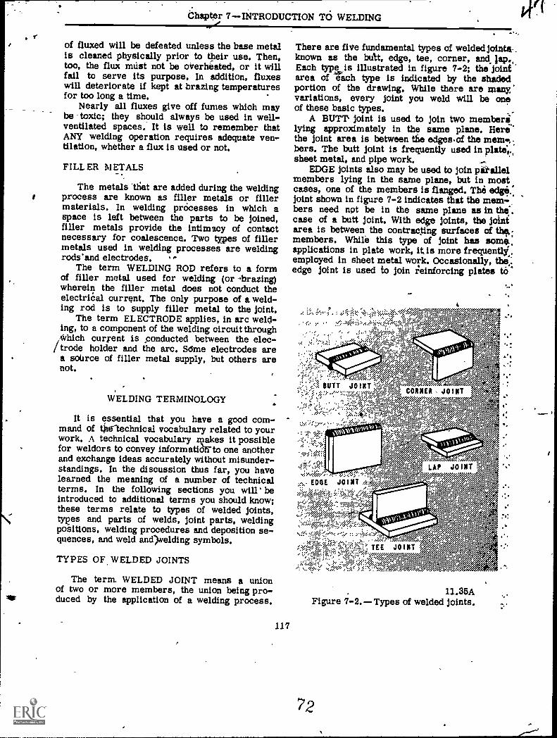
There are fiVe fundamental types of weldedjointa..known as the butt, edge, tee, corner, andEach type is illustrated in figure 7-2; the Jointarea of each type is indicated by the shadedportion of the drawing. While there are manyvariations, every joint you weld will be oneof these basic types.
A BUTT joint is used to join two memberilying approximately in the same plane. Herethe joint area is between the edges.of the mem....bers. The butt joint is frequently used in plati,sheet metal, and pipe work.
EDGE Joints also may be used to join parallelmembers lying in the satne plane, but in mostcases, one of the members is flanged. The edge..joint shown in figure 7-2 indicates that the mem-bers need npt be in the same plane as in the.case of a butt joint. With edge Joints, the Jointarea is between the contracting surfaces of the,:members. White this type of joint has soma.applications in plate work, it is more frequentlj.,employed in sheet metal work. Occasionally, thee:edge joint is used to join xleinforcing plates ti)
117
4
-0;
*OrgparefLAP JO INT
11.35AFigure Types of welded joints.
7.-
STEELWOIIKLIt 3 dt 2
A SQUARE GBOOVE WELD
<
B SQUARE GROOVE WELD
C SINGLE-BEVEL GROOVE WELD
-ir-- ,---
0 dOUBLE-BEVEL GROOVE WELD
. E SINGLE-VEE GtiOOVE WELD F 0OUBLE-VEE GROOVE WELO r"
G SINGLE-4 GROOVE WELO
1 SINGLE-U GROOVE WELO
0OUBLE-4 GROOVE WELD
1 OOUBLE-U GROOVE WELO
11.37Figure 7-3, Standard groove welds.
Aft
Chapter 7INTRODUCTION TO WELDING
STAGGERED INTERMITTENT FILLET WELDING CHAIN INTERMITTENT FIL4T WELDING,
BOXING FILLET
11.36Figure 7-4. Fillet welds.
the flanges of I-beams and the edges of angles.In many cases, no filler metal is used in join-ing edge joints by the gas welding process. Theedges are fused together and the bow metalsupplies the weld filler metal.
TEE joints and CORNER joints are used tojoin two members located at apprwdmately right
119
angles to each other. The joint area in bothcases is bitween the end of pne member andthe side or edge of another. Where the cornerjoint forms an L-shape, the tee joint has theshape of the letter T. Corner joints are usedin making tanks, boxes, box frames, and similarobjects. These joints are used only in very low
s
-0
..
STEELWORKER 3 & 2
pressure tanks since the root of the weld is in, tension under load. Tee joints have uses' in many,
types of metal structures.The LAP JOINT is used to join *overlapping
m,Imbers of a structure. The joint area of a lapjr,int is between the parallel surfaces of themembers. Lap joints are used frequently intorch brazing processes where capillary actiondraws filler metal into the ipace between thehot surfaces. 'Lap joints are also used in manyresistance welding processes, especially in sheetmetal structures fabricated with spot welds.
TYPES OF WELDS
There are many types of welds. Some of thecommon types which will concern you in your
. work are: groove, fillet, surfacing, tack, plug,slot, spot, and seam. Incidentally, you mayoften hrtr welding operators use the term "sealweld.' This term does not actually refer to anyone type of weld; rather, a seal weld is anyweld that is designed primarily to provide aspecific degree of tightness against leakage.,Seal welds are frequently used to seal threadedpipe connections and to prevent corrosive ele-ment from entering the ends of lap joints.
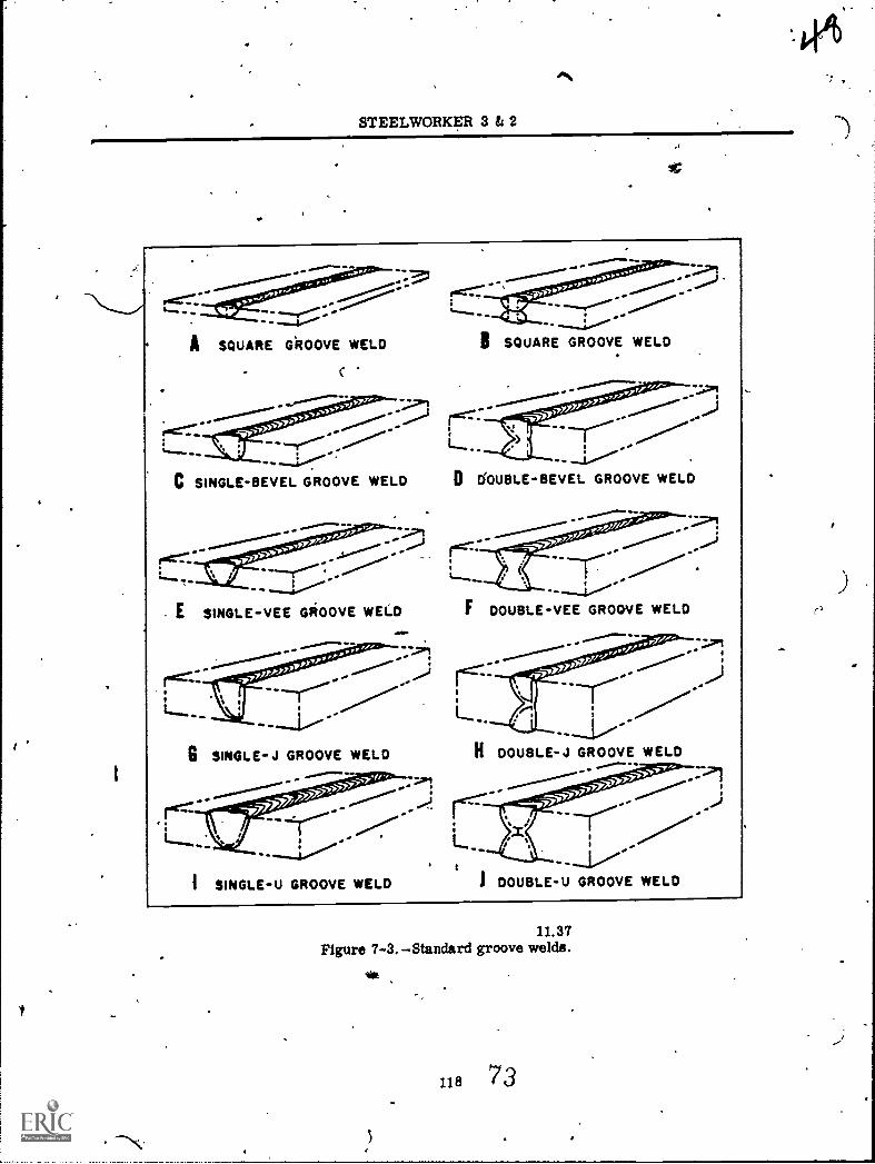
GROOVE WELDS are made in a speciallyprepared groove between two members to bejoined. Figure 7-3 illustrates a number of vari-ations of the groove weld. Note inparticularthe square, single bevel, and single-V typesbecause you will use these grooves frequentlyin welding operations. .
Choice of groove welds depends largely uponthe accessibility and the design of the part beingfabricated, and upon the degree of joint pene-tration that will be possible. If the square grooveweld is suitable to the job, select it for reasons
, of econtany, since it requires no chamfering;which means there is no edge preparation.
S.
,
k
While the. edge of a vertical pJte of a teejoint is sometimes beveled for v, ding, groovesare most frequently used for butt joints in plate ,
and pipe work. Groove welds are designed toprovide the strength required, with a minimumamount of filler metal- Plate edges may beprepared for groove welding by flame cutting,shearing, machining, chipping, or gririding.
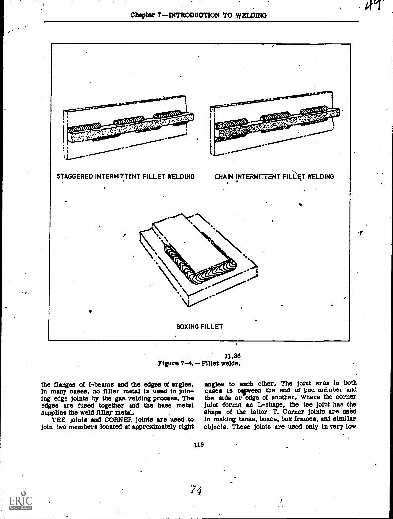
A FILLET WELD is approximately triangularin cross section, It joins two surfaces that areat approximately right angles to each other.Fillets itre used to weld lap, tee, and cornerjoints. As shown in figure 7-4, some variationsof the fillet weld are chain intermittent, staggeredintermittent, and boxing.
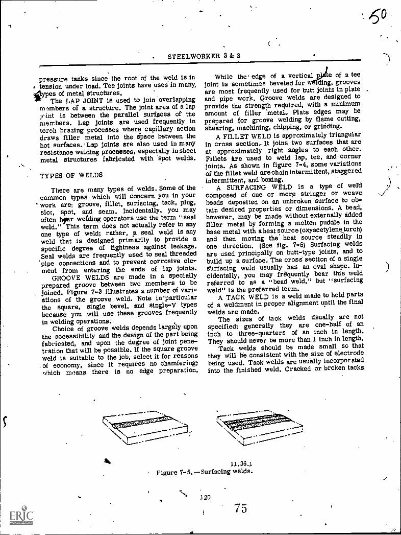
A SURFACING WELD is a type of weldcomposed of one or more stringer or weavebeads deposited on an unbroken surface to ob-tain desired properties or dimensions. A bead,however, may be made without externally addedfiller metal by forming a molten puddle in thebase metal with a heat source (oxyacetylenktorch)and then moving the heat source steadily inone direction. (See fig. 7-5) Surfacing weldsare used principally on butt-type joints, and tobuild up a surface. The crose section of a singles'urfacing weld usually has an oval shape. In-cidentally, you may frequently bear this weldreferred to as a "bead weld," but "surfacingweld" is the preferred term.
A TACK WELD is a weld made to hold partsof a weldment in proper alignment until the finalwelds are made.
The sizes of tack welds dsually are notspecified; generally they are one-half of aninch to three-quarters of an inch in length.They should never be more than 1 inch in length.
Tack welds should be made small so thatthey will lie consistent with the size of electrodebeing used. Tack welds are usually incorporatedinto the finished weld. Cracked or broken tacks
11.36.1' Figure 7-5. Surfacing welds.
-,\. 120
175
4
../
r
)
,
IChapter 7 INTRODUCTION TO WELDING
must be chipped out before the joint is finallywelded.
Plug and slot welds are used to join over-lapping plates not otherwise accestible for weld-ing. They may be used to join face-hardenedplate from the back or soft,side, 'to instill linermetals inside tanks, or to fill up a hole in aplate.
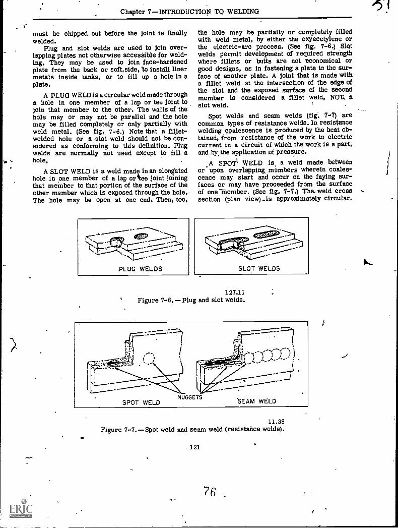
A PLUG WELD is a circular weld made througha hole in one member of a lap or tee joint tojoin that member to the other. The walls of thehole may or may not be parallel and the holemay be filled completely or only partially withweld metal. (See fig. 7-6.) Note that a fillet-welded hole or a slot weld should not be Con-sidered as conforming to this definition. Plugwelds are normally not used except to fill ahole.
A SLOT WELD is a weld made in an elongatedhole in one member of a lap orAee joint joiningthat member to that portion of the surface of theother member which is exposed through the hole.The hole may be open at one end. Then, too,
.1
-
PLUG WELDS
the hole may be partially or completely filledwith weld metal, by either the oxyacetylene orthe electric-arc process. (See fig. 7-6.) ,Slotwelds permit development of required strengthwhere fillets or butts are not economical orgood designs, as in fastening a plate to the sur-face of another plate. A joint that is made witha fillet weld at the intersection of the edge ofthe slot and the exposed surface of the secondmember is considered a fillet weld, NOT, aslot weld.
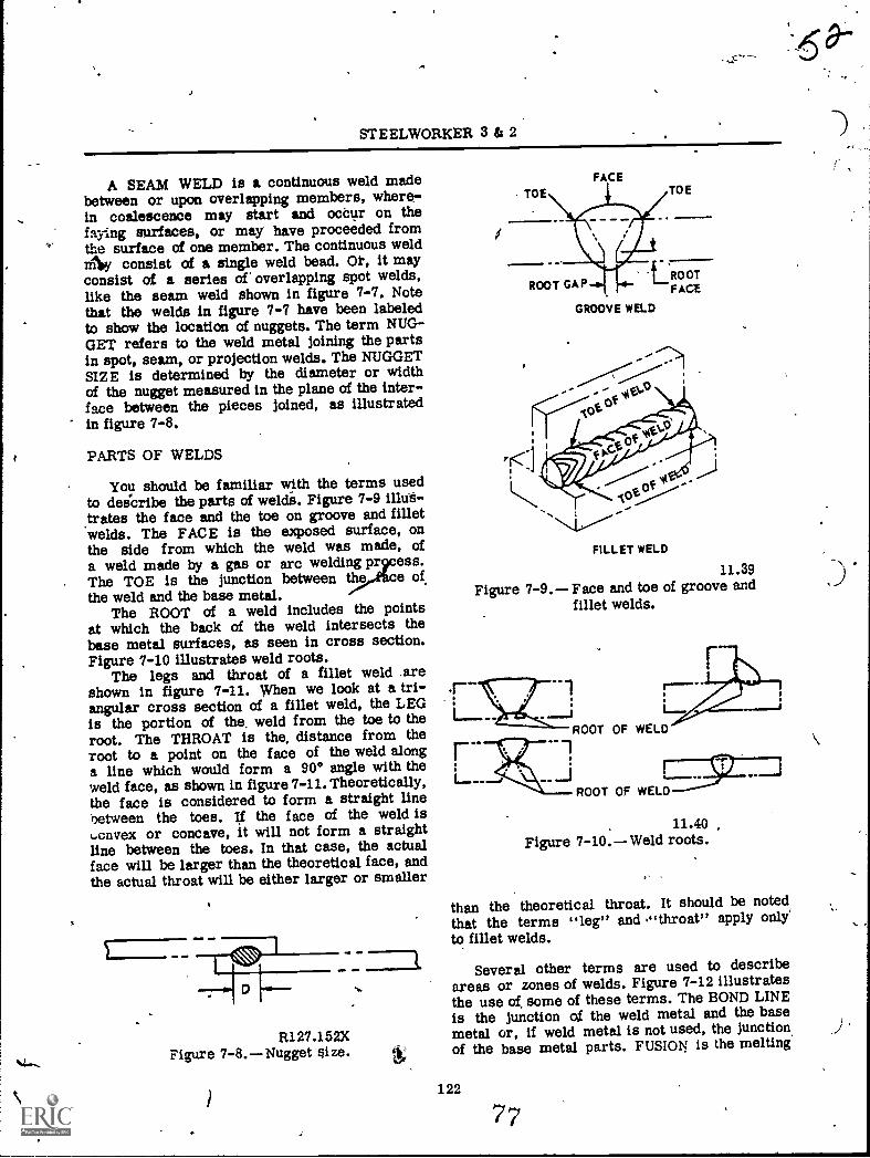
Spot welds and seam welds (fig: 7-7) arecommon types of resistance welds. In resistancewelding coalescence is produced by the heat ob-tained, from resistance of the work to electriccurrent in a circuit of which the work is a part,and by,the application of pressure.
A SPOT1 WELD is a weld made betweenor upon overlapping members wherein coales-cence may start and occur on the faying sur-faces or may have proceeded from the surfaceof one -Member. (See fig. 7-7.) The- weld crosssection (plan view) is approximately circular.
127.11Figure 7-6. Plug and slot welds.
11.38Figure 7-7. Spot weld and seam weld (resistance welds).
. 121
76
STEELWORKER 3 & 2
A SEAM WELD is a continuous weld madebetween or upon overlapping members, where-in coalescence may start and ocCur on thelaying surfaces, or may have proceeded fromthe surface of one member. The continuous weldmlky consist of a single weld bead. Ot, it mayconsist of a series of' overlapping spot welds,like the seam weld shown in figure 7-7. Notethat the welds in figure 7-7 have been labeledto show the location of nuggets. The term NUG-GET refers to the weld metal joining the partsin spot, seam, or projection welds. The NUGGETSIZE is determined by the diameter or widthof the nugget measured in the plane of the inter-face between the pieces joined, as illustratedin figure 7-8.
PARTS OF WELDS
You should be familiar with the terms usedto deicribe the parts of welds. Figure 7-9 illus-.trates the face and the toe on groove and filletwelds. The FACE is the exposed surface, onthe side from which the weld was made, ofa weld made by a gas or arc welding pr ess.The TOE is the junction between thq,Ace of,the weld and the base metal.
The ROOT of a weld includes the pointsat which the back of the weld intersects thebase metal surfaces, as seen in cross section.Figure 7-10 illustrates weld roots,
The legs and throat of a fillet weld .areshown in figure 7-11. When we look at a tri-angular cross section of a fillet weld, the LEGis the portion of the, weld from the toe to theroot. The THROAT is the, distance from theroot to a point on the face of the weld alonga line which would form a 90° angle with theweld face, as shown in figure 7-11.Theoretically,the face is considered to form a straight linebetween the toes. If the face of the weld isL..cnvex or concave, it will not form a straightline between the toes. In that case, the actualface will be larger than the theoretical face, andthe actual throat will be either larger or smaller
R127.152XFigure 7-8. Nugget aize.
TOE
FACETOE
ROOTROOT GAP FACE
GROOVE WELD
'40V
FILLET WELD
11.39Figure 7-9. Face and toe of groove and
fillet welds.
ROOT OF WELD
11.40Figure 7-10. Weld roots.
than the theoretical throat. It should be notedthat the terms "leg" and ,"throat" apply only'to fillet welds.
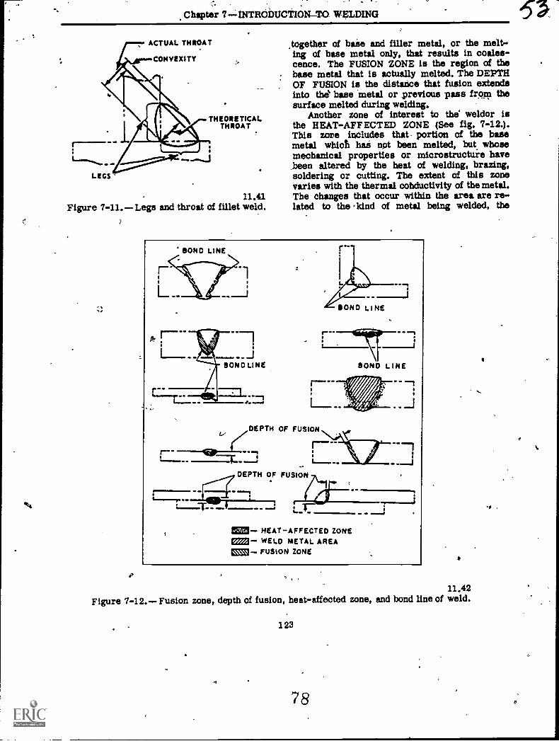
Several other terms are used to describeareas or zones of welds. Figure 7-12 illustratesthe use of some of these terms. The BOND LINEis the junction of the weld metal and the basemetal or, if weld metal is not used, the junctionof the base metal parts. FUSION is the melting
122
7
Chapter 7INTRODUCTION-TO WELDING
ACTUAL THROAT tOgether of base and filler metal, or the melt-CONVEXITY
ing of base metal only, that results in coales-cence. The FUSION ZONE is the region of thebase metal that is actually melted. The DEPTHOF FUSION is the distance that fusion extendsinto the base metal or previous pass froro thesurface melted during welding.
THEORETICAL Another zone of interest to the weldor isTHROAT the HEAT-AFFECTED ZONE (See fig. 7-12.).
This zore includes that portion of the basemetal which hai not been melted, but whosemechanical properties or microstructuie havebeen altered by the heat of welding, brazing,
LEGS soldering or cutting. The extent of this zonevaries with the thermal cohductivity of the metal.
11.41 The changes that occur within the area are re-Figure 7-11. Legs and throat of fillet weld. lated to the Idnd of metal being welded, the
4 BOND LINE
.BOND LINE
zDEPTH OF FUSION
rDEPTH OF FUSION
- HEAT-AFFECTED ZONEa233- WELD METAL AREAEms!- FUSION ZONE
11.42Figure 7-12.-- Fusion zone, depth of fusion, heat-affected zone, and bond line of weld.
123
7 8
1
sir ELWORKER 3 & 2
intensity and ation of heat, and the controlembodied in the elding procedure.
PARTS OF JOIN
In order to follwelding job, you muedge of the termsjoints. In some caseterms used to descrthose used to descrilead to confusion. Fora weld is NOT preciselof a joint. In other casesdifficult to decide whetherto a part of a weld orall cases, it is essential thatwhat part, zone, or measureme
the specifications for anyt have a very clear knowl-
to describe welds and, the similarity betweenbe parts of welds and
parts of joints mayexample, the root ofthe same as the rootit may be somewhat
terrifegly refersa part of a joint. Inou know EXACTLYUs being referred
to.While there are many gr. ove designs, the
various parts of the joint ar described _by
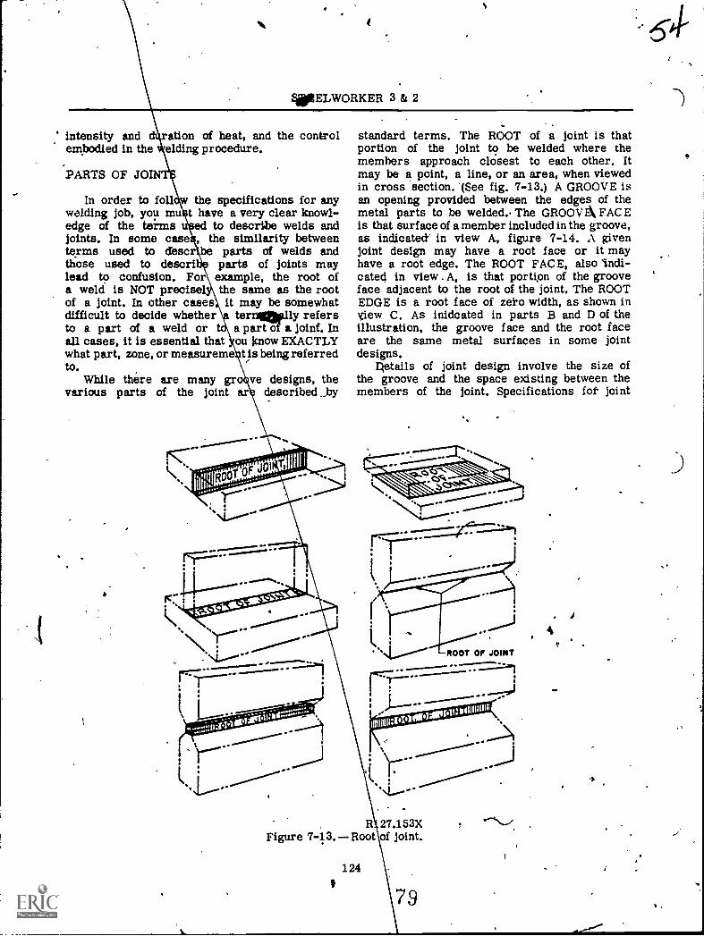
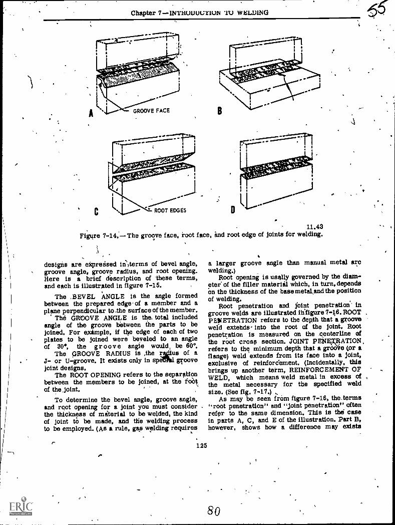
standard terms. The ROOT of a joint is thatportion of the joint to be welded where themembers approach closest to each other. Itmay be a point, a line, or an area, when viewedin cross section. '(See fig. 7-13.) A GROOVE isan opening provided between the edges of themetal parts to be welded.. The GROOV E FACEis that surface of a member included in the groove,as indicated in view A, figure 7-14. A givenjoint design may have a root face or it mayhave a root edge. The ROOT FACE, also indi-cated in view . A, is that portipn of the grooveface adjacent to the root of the joint. The ROOTEDGE is a root face of zeto width, as shown inyiew C. As inidcated in parts B and D of theillustration, the groove face and the root faceare the same metal surfaces in some jointdesigns.
getails of joint design involve the size ofthe groove and the space existing between themembers of the joint. Specifications fot joint
)------111111111:144000Mustiiilltur
ROOT Of JOINT
R 27.153XFigure 7-13. Root of joint.
124
7 9
4e
J
Chapter 7INTiWIJUL7111.41 '11) WELDING
11.43Figure 7-14. The groove face, root face, and root edge of joints for welding.
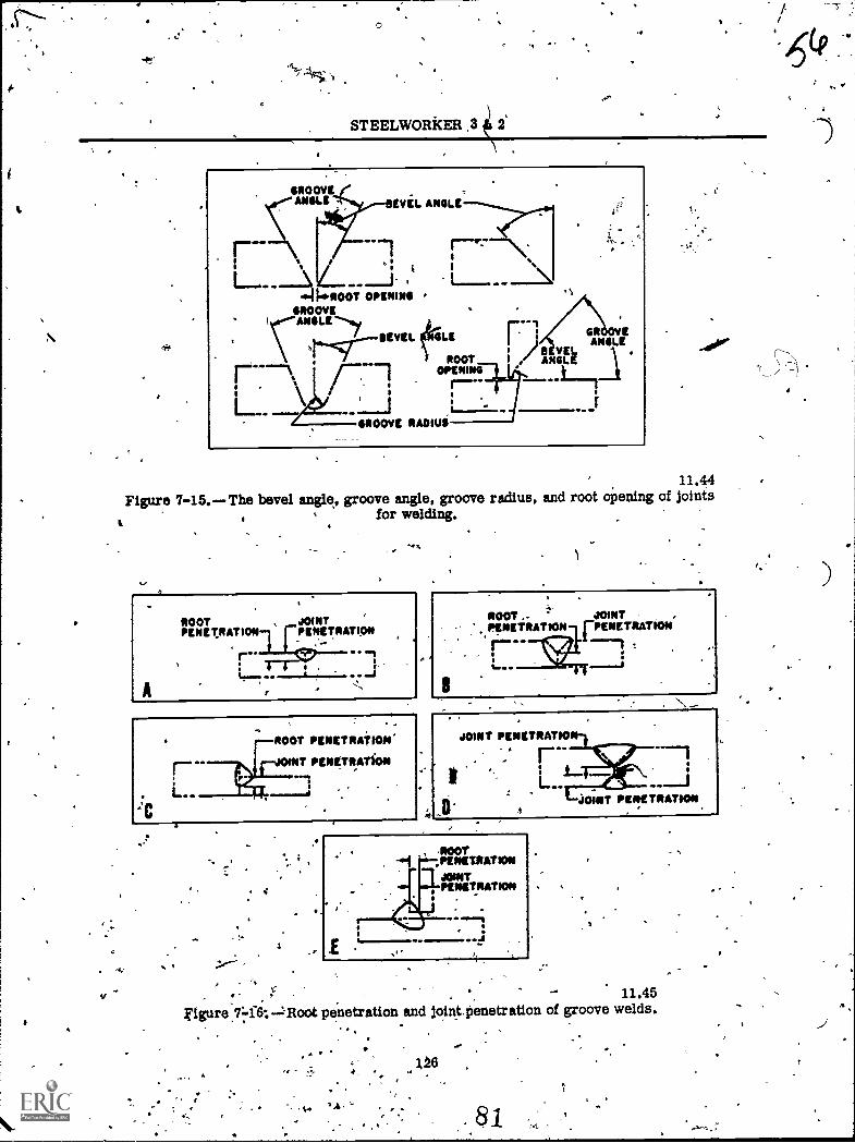
designs are ekpreised iii:terms of bevel angle,groove angle, groove radius, and root opening.Here is a brief description of These terms,and each is illustrated in figure 7-15.
The .BEVEL ANGLE is the angle formedbetween the prepared edge of a member and aplane perpendicular to lhe surf ace of the member.
The GROOVE ANGLE is the, total includedangle of the groove between ihe parts to bejoined. For example, if the edge of each of twoplates to be joined were beveled to an angleof 30°, the gr oove angle would, be 600.
The GROOVE RADIUS is ythe takiius of aJ- or U-groove. It exists only in spai groovejoint designs.
The ROOT OPENING refers to the separationbetween the members to be joined, at the `fob.,of the joint.
To determine the bevel angle, groove angle,and root opening for a joint you must considerthe thickness of miterial to be welded, the kindof joint tO be made, and the welding processto be employed. (As a rule, gap welding requires
ft125
Y".
.\
a larger groove angle than manual metal arcwelding.)
Root opening is usally governed by the diam-eter of the filler material which, in turn, dependsOn the thickness of the base metaland the positionof welding.
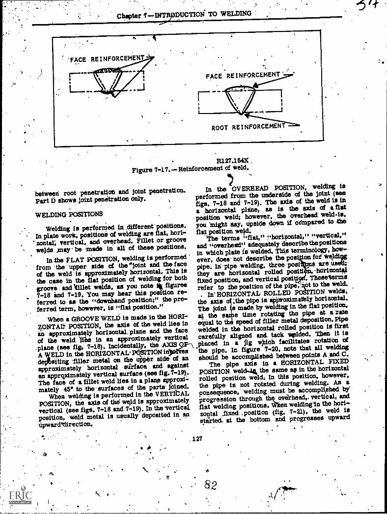
Root penetration and Saint penetration ingroove welds are illustrated iiifigure 7-16. ROOTPENETRATION refers to the depth that a grooveweld extends into the root of the joint. Rootpenetration is measured on the zanterline ofthe root cross section. JOINT PENERRATION.refers to the minimum depth that a grOdie (or aflange) weld extends from its face into a joint,exclusive of reinfordernent. (Incidentally, thisbrings up another term, REINFORCEMENT OFWELD, which means weld metal in excess ofthe metal necessary fox the specified weldsize. (See fig. 7-17.) ,
As may be seen from figure 7-16, the.terms"root penetration" and "joint penetration" oftenrefer to the same dimension. This is the easein parts A, C, and E of the illustration. Part B,however, shows how a difference may exists
80
t
STEELWORkER ,3
11.44Figure 7-15.The bevel angle, groove angle, groove radius, and root opening of joints
for welding.
ft
- ,
' t.-4f ' ' - 11.45
Figure.7.71.6.-Root penetration and joint.penetration of groove welds.
'I
24.=
1.26
Chacter DUCTIOd TO WELDING
R127.154XFigure 7-17. Reinforcement of weld.
betweed root penets.atioli and joint penetration.Part D shows joint penetration only.
WELDING POSITIONS
Welding is perfOrMed in different positions.In plate work, positions of welding are flat, hori-zontal; vertical, and overhead. Fillet or groovewelds ,may be -made in all of these positions.
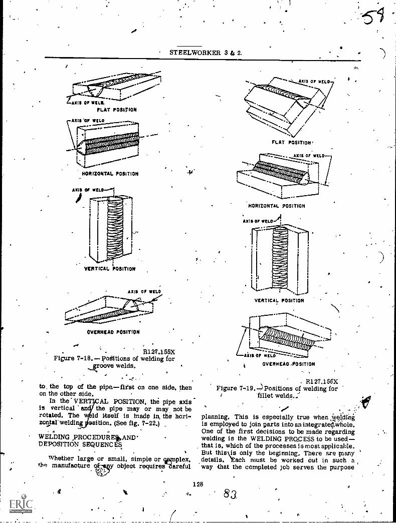
In the FLAT POSITION, welding is performedfrom the upper side of the 'joint and the faceof the weld ii approximately horizontal. This isthe que in the flat position of welding for bothgroove and Ifillet welds, as you note it figures7-18 ind 7-19. You msy hear this position re-ferred to as the "downhand position;" the pre-ferred term, however, is "flat position,".
When a GROOVE WELD is made in the HORT-ZONTAt. POSITION, the axis Of the weld lies inin approximately horizontal__ plane and the faceof the weld Iles in an approximately verticalplane (see fig, 7-18). Incidentally, the AXIS 0A tfiELD in the HORIZONTAL' PetsITION indeplbsiting -filler metal on the utOer side of anapproximately horizontal stirface and againstan apprqximately vertical surface (see fig. 7-19).The face of -a fillet weld lies. in a plane approxi-mately 45' to the surfaces of the parts joined.
When welding is performed in the VERTIbALPOSITION, the axis of the' weld is approximatelyvertical (see figt. 7-18 and 7-19). In the vertical,position, weld metal is usually deposited in an,iipwarditlirecti on.
\ ,
In the OVERHEAD POSITION, welding isperformed from the underside of the joint (seefigs, 7-18 and 7-19). The axis of the weld is ina ,borizontal plane, as is the axis of a flatposition weld; however, the overhead weld.is,you 'might may, upside down if cdmpared to theflat position we)d.
The terms "flat," "horizontal," "vertical,"and "overhead" adequately describe thepositionsin which plate is' welded. Thi,s terminology, how-ever, does not describe the po - on fof iVeldlogpipe. In- pipe welding, three posi .t useU
they are horizontal rolled posit! -horizont#fixed position, and vertical positi . Thesetermsrefer to the position of the pipe, 'got to -the weld.
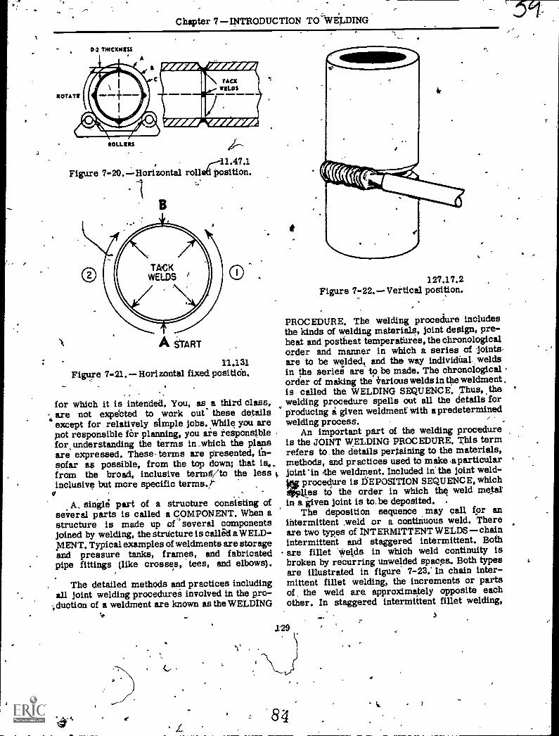
In' HORIZONTAL ROLLED POSITION welds,the axis o1 ;the pipe is ipixroximately horizontal.The pint s made by welding in the flat position,at the aaiie time rotating the pipe at a rateequal to th speed of filler metal deposition. Pipewelded in the horizontal rolled position id firstcarefully aligned and- tack Added. Then it isplaced in a fig wpich facilitates rotation of"the pipe. In figure 7-20, note that all weldingshould be accomillished between points A and C.
The pipe axis in a HORIZONTAL FIXEDPOSITION weld-4, the same ae in the horizontalrolled position weld: In this position, however,the pipe is not rotated during welding. As aconsequence, welding -must be acoompliphedprogression through the oviii.head,. vertical, andflat welding positions. When weldingin the hori..zorltal Axed _position (fig. 7-21), the weld isstarted, at the bottom and progresses upward
127
4
STEELWORKER 3 & 2.
AXI3 OF 1131.11
FLAT POSITION
HORIZONTAL POSITION
VERTICAL POSITION
OVERHEAD POSITION
R127.155XFigure 7-18. positions of welding for
groove welds.
to. the top of the pipefirst on one side, thenon the other side.
In the VERTICAL POSITION, the pipe axisis vertical an the pipe may or may not berotated. The w ld itself is hiadp In the hori-zontal- welding osition. (See fig, 7-22.)
WELDING ,PROC EDURE*ANDDEPOSITION SEQUENC ES
Whether large or small, simple or wriplex,tbR manufacture ty object requiresdareful
a v4. 4.
7......""&tIS Or 'ACLO
FLAT POSITION '
HORIZONTAL POSITION
VERTICAL POSITION
A OVERHEAO .POSITION
. R127.156XFigure 7-19,-4 Positions of welding for
fillet welds..: .
0
planning, This is especially true when ,Iyeldingis employed to join parts into an integrated/whole.One of the first decisions to be made regardingwelding is the WELDING PROCESS to be used,that Is, which of the processes is most applicable.But this \is only the beginning. There axe manydetails. 'Each must be worked Out in such away that the completed job serves the purpose
128
83
Chspter 7INTRODUCTION TO -WELDING
SOLLER,S
r--11.47.1Figure 7-20.LHorizontal rolled position.
A th'ART
11.131Figure 7-21. Horizontal fixed positidn.
,
for which it is intended. You, as a third class,- are not expected to work out" these details4 except for relatively simple jobs. While you are
not responsible fOr planning, you are responsiblefor, understanding the terms in ,wMch the plansare expressed. These- terms are presented, th-spfar as possible, from the top down; thatfrom the broad, inclusive termg/to the less t.inclusive but more specific terms.,"
A. single part of a structure consisting ofseieral parts is called a COMPONENT. Wben astructure is made up of several componentsjoined by welding, the strticture is canal a WELD-MENT. Typical examples of weldments are storageand pressure tanks, frames, and fabricatedpipe fittings (like crosses, tees, and elbows).
, The detailed methods and practices includingall joint welding procedurei involved in the pro-
;cluction of a weldment are known as the WELDING
127.17.2Figure 7-22. Vertical position.
PROCEDURE. The welding procedure includesthe kinds of welding materials, joint design, pre-heat and postheat temperatures, the chronologicalorder and manner in which a series of 'joints,are to be welded, and the way individnal weldsin the seriegi are to be made. The chronological rorder of making the +arious welds in the weldmentis called the WELDING SEQUENCE. Thus,thewelding procedttre spells Out all the details forproducing i given weldment with a predeterminedwelding process.
An important part of the welding procedureis the JOINT WELDING PROCEDURE. This termrefers to the details pertaining to the materials,methods, and practices used to make.aparticularjoint 'in the weldment. included in' the joint weld-ing procedure is tEPOSITION SEQUENCE, which#4.4,es tO the order in which the weld metalin a given joint is to be deposited. .
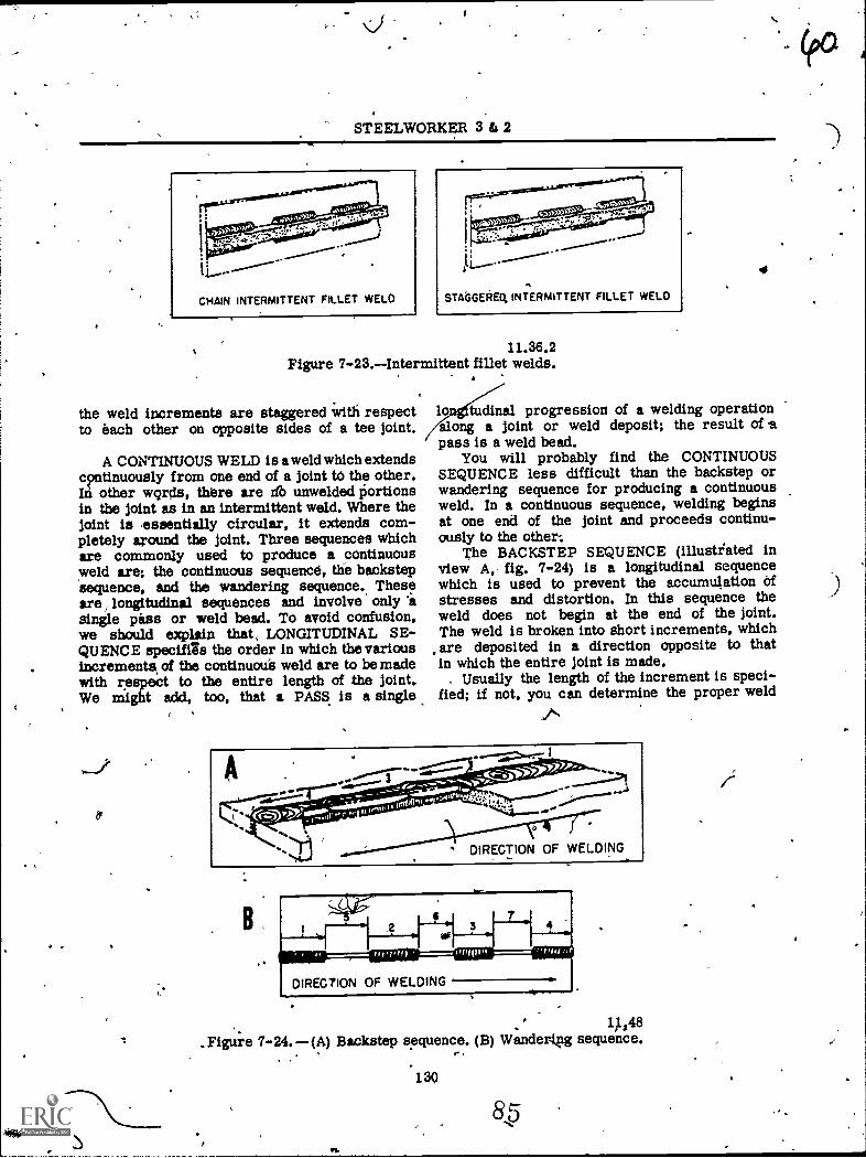
The deposition sequence may call fpr anintermittent ,weld or a continuous weld. Thereare two types of INTERMITTENT WELDSchainintermittent and staggered intermittent. Bothare fillet Vields in which weld continuity isbroken by recurring unwelded spaces,. Both typesare illustrated in figure 7-23.* In chain inter-mittent fillet welding, the increments or partsof the weld are approximately opposite eachother. In staggered intermittent fillet welding,
-
-
i \
STEELWORKER 3 fa 2
i
..
STAdGEOEQ INTERMITTENT FILLET WELD
11.36.2Figure 7-23.Intermittent fillet welds.
the weld increments are staggered with respectto each other on opposite sides of a tee joint.
A CONTINUOUS WELD is a weld which extendsc?ntinuously from one end of a joint tO the other.In other wqrds, there axe lib unwelded liortionsin the joint as in an intermittent weld. Where thejoint is .essentially circular, it extends com-pletely around the joint. Three sequences whichare commonly used to produce a continuousweld are; the continuous sequence, the backstepsequence, and the wandering sequence.. Theseare, longitudinal sequences and involve only 'asingle pass or weld bead. To avoid confusion,we should explain that, LONGITUDINAL SE-QUENCE specifils the order in which the variousincrements, of the continuoue weld are to be madewith respect to the entire length of the joint.We might add, too, that a PASS. is a single
, .
-
4
lo tudinal progression of a welding operationalong a joint or weld deposit; the result of apass is a weld bead.
You will probably find the CONTINUOUSSEQUENCE less difficult than the backstep orwandering sequence for producing a continuousweld. In a continuous sequence, welding beginsat one end of the joint and proceeds continu-ously to the other:
The BACKSTEP SEQUENCE (illustrated inview A, fig. 7-24) is a longitudinal sequencewhich is used to prevent the accumulation ofstresses and distortion. In this sequence theweld does not begin at the end of the joint.The weld is broken into short increments, whichare deposited in a direction opposite to thatin which the entire joint is made.
. Usually the length of the increment is speci-fied; if not, you can determine the proper weldf
DIRECTION OF WELDING
1$ 1 s48._Figure 7-24. (A) Backstep sequence. (B) Wander.kng sequence.
' '
*T.
,E0
-
/
;
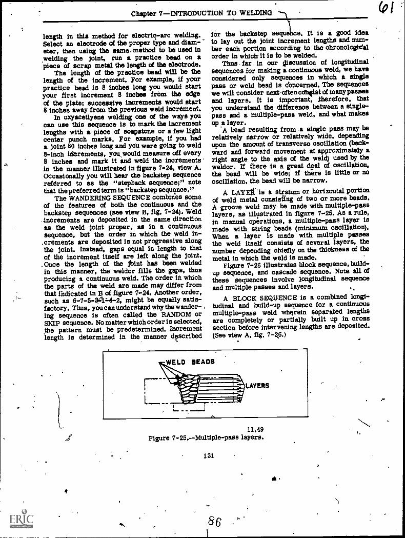
Chapter 7INTRODUCTION TO WELDING
length in this method for electric-arc welding.Select an electrode of the proper type and diam-eter, then using the same, method to be used inyielding the joint, run a practice bead on apiece of scrap metal the length of the electrode.
The length of the practice bead will be thelength of the increment. For example, if yourpractice bead is 8 inches long you would startyour first increment 8 inches from the edgeof the plate; successive increments would start8 inches away from the previous weld increment.
In oxyacetlyene welding one of the ways youcan use this sequence is to mark the incrementlengths with a piece of soapstone or a few lightcenter punch marks. For example, if you hada joint 80 inches long and yOu were going to weld8-inch inerements, yotkwould measure off every8 inches and mark it and weld the increments .in the manner illustrated in figure 7-24, view A.Occasionally you will bear the backstep sequencereferred to as the "stepback sequence;" notethat the preferred term is "backstep sequence."
The WANDERING SEQUENCE combines someof the features of both the continuous and thebackstep sequences (see view B, fig. 7-24). Weld
- increments are deposited in the same directionas the weld joint proper, as in a continuoussequence, but the order in which the weld in-.crements are deposited is not progressive alongthe joint. Instead, gaps equal in length to thatof the increment itself are left along the joint.Once the length of the jbint has been weldedin this manner, the weldor fins the gaps, thusproducing a continuous weld. The order in whichthe parts of the weld are made may differ fromthat Indicated in B of figure 7-24. Another order,such as 6-7-5-34z4-2, might be equally satis-factory. Thus, you can understand why the wander-ing sequence is often called the RANDOM orSKIP sequence. No matter which order is selected,the pattern must be predetermined. Incrementlength is determined in the manner described
4
for the backstep sequeice. It is a good ideato lay out the joint increment lengths and num-ber each portton according to the chronologiealorder in which it is to be welded.
Thus. far in our sjiscussion of longitudinalsequences for making a continuous weld, we haveconsidered only aequences in which a singlepass or weld bead is doncerned. The sequenceswe will consider next .often coNist of many passesand layers. It is important, therefore, thatyou understand the difference between a single-pass and a multiple-pass weld, and what makesup & layer.
A bead resulting from a single pass may berelatively narrow or relatively wide, dependingupon the amount of transverse oscillation (back-ward and forward movement at approximately aright angle to the axis of the weld) used by theweldor. If there is a great deal of oscillation,the bead will be wide; if there is little or nooscillation, the bead will be narrow.
A LAYEit-is a stratum or horizontal portionof weld metal consisting of two or more beads.A groove weld maly be made with multiple-passlayers, as illustrated in figure 7-25. As a rule,in manual operations, a multiple-pass layer ismade with string beads (minimura oscillation).When a layer is made with multiple passesthe weld itself consists of several layers, thenumber depending chiefly on the thickness of themetal in which the weld is made.
Figure 7-26 illustrates block sequence, build-up sequence, and cascade sequence. Note all ofthese sequences involve longitudinal sequenceand multiple passes and layers.
A BLOCK SEQUENCE is a combined longi-tudinal and build-up sequence for a continuousmultiple-pass weld wherein separated lengthsare completely or partially built up in crosssection before intervening lengths are deposited.(See view A, fig. 7-2.6.)
11.49Figure 7-25.Multiple-pass layers.
131
8 6
*
(0 I
I.
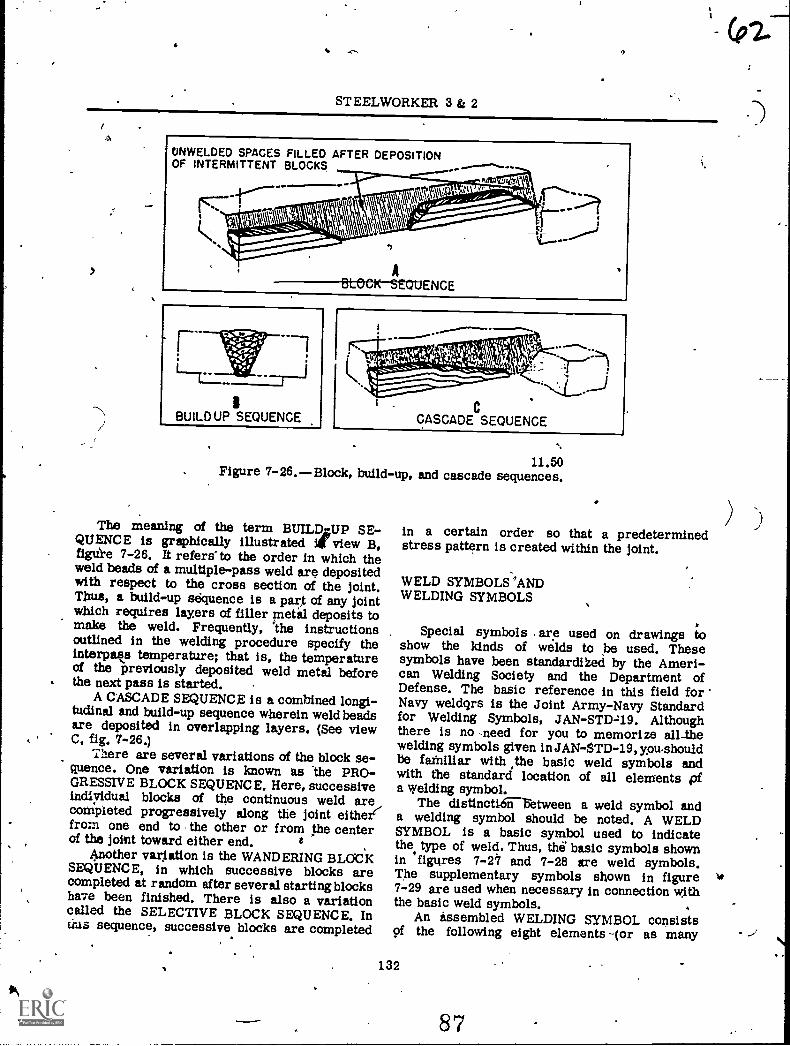
STEELWORKER 3 & 2
ONWELDED SPACES FILLED AFTER DEPOSITIONOF INTERMITTENT BLOCKS
1BUILDUP SEQUENCE
11.50Figure 7-26.Block, build-up, and cascade sequences.
The meaning of the term BUILD,,,-UP SE-QUENCE is graphically illustrated view B,figue 7-26. It refersto the order in which theweld beads of a multiple-pass weld are depositedwith respect to the cross section of the joint.Thus, a build-up sequence is a part of any jointwhich requires layers of filler metal deposits tomake the weld. Frequently, `the instructionsoutlined in the welding procedure specify theinterparts temperature; that is, the temperatureof the previously deposited weld metal beforethe next pass is started.
A CASCADE SEQUENCE is a combined longi-tudinal and build-up sequence wherein weld beadsare deposited in overlapping layers. (See viewC, fig. 7-26.)
There are several variations of the block se-quence. One variation is known as The PRO-GRESSIVE BLOCK SEQUENCE. Here, successiveindiyidual blocks of the continuous weld are_,compteted progressively along the joint eitheefrom one end to the other or from the centerof the joiint toward either end.
Another variation is the WANDERING BLOCKSEQUENCE, in which successive blocks arecompleted at random after several startingblocksha7e been finished. There is also a variationcalled the SELECTIVE BLOCK SEQUENCE. Incats sequence, successive blocks are completed
in a certain order so that a predeterminedstress pattern is created within the joint.
WELD SYMBOLS 'ANDWELDING SYMBOLS
Special symbols are used on drawings toshow the kinds of welds to be used. Thesesymbols have been standardiked by the Ameri-can Welding Society and the Department ofDefense. The basic reference in this field forNavy weldqrs is the Joint Army-Navy Standardfor Welding Symbols, JAN-STD-119. Althoughthere is no Ileed for you to memorize all-thewelding symbols given inJAN-STD-19, you-shouldbe faMillar with ,the basic weld symbols andwith the standard location of all elements pfa welding symbol.
The disttnctitween a weld symbol anda welding symbol should be noted. A WELDSYMBOL is a basic symbol used to indicatethe type of weld. Thus, this' basic symbols shownin 'figures 7-27 and 7-28 are weld symbols.The supplementary symbols shown in figure7-29 are used when necessary in connection vdththe basic weld symbols.
An assembled WELDING SYMBOL consistsof the following eight elements -Or as many
132
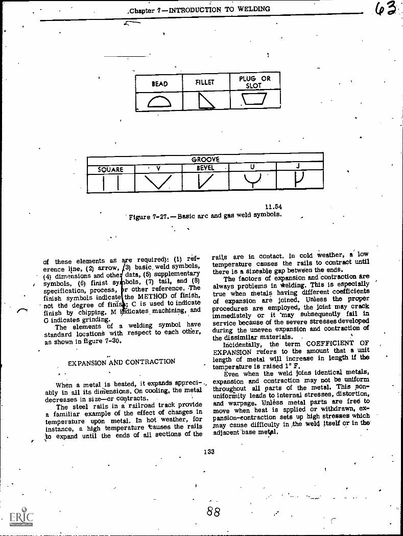
I.
,Chapter 7INTRODUCTION TO WELDING
BEAD FILLETPLUG OR
SLOT
L =,...
GROOVE
SQUARE ' V BEVEL U J
, I I Y _ I)
of these elements aserence line, (2) arrow,(4) dimensions and othesymbols, (6) finist syspecification, process,finish symbols indicatenot the degree of fiafinish by chipping, MG indicates grinding.
The elements Of astandard locationè withas shown in figure 7-30.
11.54Figure 7-27.Basic arc and gas weld symbols.
e required); (1) ref-3) basic, weld symbols,data, (5) supplementarybols, (7) tail, and (8)r other reference. Thethe METHOD of finish,; C is used to indicateclicates, machining, and
welding symbol haverespect to each other,
EXPANSION AND CONTRACTION
When a metal is heated, it expands appreci-ably in all its diniensions. On cooling, the metaldecreases in sizeor contracts.
The steel rails in a railroad track providea familiar example of the effect of changes intemperature upon metal. In hot weather, forinstance, a high temperature tauses the railsto expand until the ends of all sections of the
rails are in contact. In cold weather, a- lowtemperature causes the rails to contract untilthere is a sizeable gap between the ends.
The factors of expansion and-contraction irealways problems in *elding. This is especiallytrue when Metals having different coefficientsof expansion are joined. Unless the properprocedures are employed, the joint may crackimmediately or it 'may subsequently fail inservice because of the severe stresses developedduring the uneven expansion and contraction ofthe dissimilar materials.
Incidentally, the term COEFFICIENT OFEXPANSION refers to the amount that a unitlength of metal wi1 increase in length if thetemperature is raised 1° F.
Even when the weld joins identical metals,expansion and contraction may not be uniformthroughout all parts of the metal. This pon-uniformity leads to internal stresses, distortion,and warpage. Unless metal parts are free tomove when heat is applied or withdrawn, ex-pansion-eontraction sets up high stresses which.may cause difficulty in /the weld ftself or in theadjacent"base metdal.
133
88
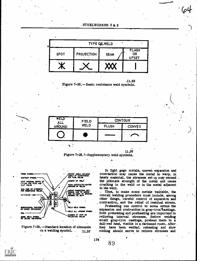
STEELWORKER 3 & 2
TYPE 0E-WELD ,
SPOT PROJECTION AFLASH
ORUPSET
)1( ..) )00(
11.55Figure 7-28.Basic resistance weld symbols.
-WELDALL
AROUND
_FIELDWELD
CONTOUR
FLUSH CON VE X
0,
11.56Figure 7-29.=Supplementary weld symbols.
Figur! 7-30..,Standard location of elementson a welding symbol. 11.57
,.4
In light gage metals, uneven expansion andcontraction may cause the metal .to warp. Inheavy material, the stresses set up may exceed ,
tbe ultimate strength of the metal and causecracking in the weld or in the metal adjacentto the weld.
Thus, to make some metals weldable, theoverall welding procedure must include, amongother things, careful control of expansion andcontraction and the relief of residual stress.
Preheating can control to some extent theexpansion and contraction in gray-irontastings.Both preheating and postheating are important inrelieving interne stresses. Before weldingsmall gray-iron outings, preheat them to adull-red heat, visible in a darkened room. After _
they have been welded, reheating and slowcooling should serve to relieve stresses and
13489
.er
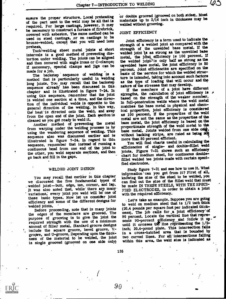
Chapter 7INTRODUCTION TO WELDING
ensure the proper structure. Local preheatingof the part next to the weld may be all that isrequired. For large castings, however, It maybe necessary to construct a furnace of firebrick,covered with asbestos. The same method can beused on steel castings, or on castings to bebronze-welded, except that you will need lesspreheat\
Tack-welding sheet metal joints at shortintervals is a good method of preventing as-
,. tortion under welding. The joints can be alignedand then secured with angle irons or C-clamps;if necessary, special clamps snd jigs can bemade for a job.
The backstep sequence of welding is amethod that is particularly useful in weldinglong joints. You may recall that the backstepsequence alres4 has been discussed in thischapter and is illustrated in figure 7-24. Inusing this sequence, remember that the jointis welded one section at a time, and the direc-tion of the , individual welds is opposite to thegeneral direction of the welding. In this way,the' heat is directed onto the weld, and awayfrom the open end of the joint. Each aection'iscleaned as you get ready to weld it.
Another method of preventing the metalfrom warping under the welding process is byusing the wandering sequence of welding. Thissequence also was discussed earlier and isillustrated in figure 7-24. In regard to thir)sequence, remember that instead of running acontinuous bead from one end of the joint tothe other, you weld separate sections, and thengo back and fill in the gaps.
WELDED JOINT DESIGN
You may recall that earlfer in this chapterwe discussed the five fundamental types of
,.weided joint butt, edge, tee, corner, and lap.It was also noted that, while' there are manyvariations; every joint you weld Will be one ofthese basic types. Now let us consider jointefficiency and some of the different designs forwelded joints.
Before proceeding, note that in many jointsthe edges of the members are grooved. Thepurpose of grooving is to give, the joint therequired strength with the use of a minimumamount of finer metal. Standard groove designsinclude the square groove, bevel groove, V!--
grove, and U-groove. Depending upon the; thick-ness of the material to be welded, the jointis single grooved (grooved on one side only)
'or double grooved '(grooved on both sides). Mostmaterials up to 3/16 inch in thickness may bewelded without grooving.
JOINT EFFICIENCY
Joint efficiency is a term used to indicate thestrength of a welded joint as compared with thestrength of the unwelded base metal. If the
kwelded joint s s as strong as the unwelded babemetal, the jo efficiency is 100 percent. Ifthe welded jo is only half as strong SS thetiawelded base metal, the joint efficiency is 50percent. Joint efficiencies are specified on thebasis of the service for which the welded struc-ture is intended, taking into account such factorsas the type of loading that will occur and thenature of the stresses that may develop.
If the members of a joint have differentgrengths, the calcidation of joint efficiency is ibased on the strength of the weaker member.In full-penetration welds where the weld metalmatches the base metal in physical and chem-ical properties, joint efficiency is consideredas 100 percent. If the properties of the weldmetal are not the same as the properties of thebase metal, the joint efficiency Is based on theproportionate strength of the weld metal to thebase metal, Joints welded from one side 0without backing strips, are rated as beingmore than 80 percent efficient.
You will find charts useful in calculating theefficiencies of single- and double-fillet weldjoints. Figure 7-31 shows. such an efficiencychart for medium steel, for continuous double-fillet welded tee joints made with certain speci-fied electrodes. ;
Study figure 7-31 and see how to use it. Whatinf9rmation ' can you get from it? First of all,knowing the size of the steel to be welded, youcan find out the eize of the fillet weld that mustbe made IN THM STEELS, WITH THE SPECI-FIED ELECTRODES, in order to obtain a jointwith the required efficiency.
Let's take an example. Suppose you are goingto weld on medium steel that is 1/2 inch thick(20.4 pounds per square foot per indicated thick-ness). The job calls for ,a joint efficiency' of90 percent. Locate the vertical line that repre-sents 90-percent efficiency and folio* it up . a°
until it crosses th.-Ir line repz-7annting the 1/2-inch; 20.4-pound plate. This intersection fallsin a cross-hatched area that is bounded bytwo curved lines. For all' intersections fallingwithin this area, the weld size is indicated as
135
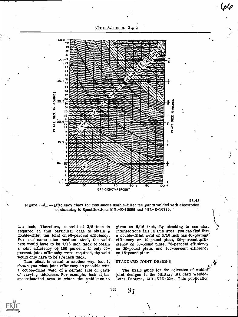
S.
xmmr mi.mtwomos:47/ zAwnAvd ;Avg/AN7 ,:sh AlticAraNk mcmq ,uma.h\ * /7 Amy n Vv0,24M4'&
W 1/ A NifUlfi"M'i ,\/1);r Al AN NAN. vphy N;., vv. ;74
7,1/f imAmmywifr zemxtyroffm,xmg i,"\V".;)7 z Nave AA, \whim MK%Ar AA )k vri AK\ y
AVA, Y AY '4W/MtCiaw Ay a uw, sNlio, 41llllll II/11/41 %%%%%% VMMI, 1,11 CM .114 %%LIMN &, WaV NW/ 'WM/ UMWANNV% 1////0// ' , xvw,w/azAlawlmm,7 Att,\NR
V7 sy /mu /ye NA \Ar hq)N MN
NNW AWi; Sf 17 int \16 AMAX AM\ / I/I/ 1,1 I I Alm\ womiwomailm, v,Awkauvaww..03I.IVIO t n't aNNMAV %\lh I I, / / l I/Fl. MINW% ts
Bk. \ NW/ A7 ; 1 NZ 47 Aikm7 41047 ohm lw,y Ja N 1K<CCONV
47.,nnMZCZgfg,===`,;;;,Z1
Ar A' N\ 1.7 ASZ. V.-1 Af A:\N NaUZan.VV71.0%/AWIAVIfil OM.: WNW VIMANA WINI,
P." "1/ if ,A1Vs\\ WNW, Jr Jr Ar Jr iM N\ xf\ \Mk% "
k NA VatIr A7 AV If AYeak k 1 weir iff Alf 470//y
maw& & Nair A7A is
N\ N\ NM\_MAW\ VIL V\ N1/4 Nk N,
Ole
Ii
s
:._.. :s
55 5
2
1
....
5
al
:
- II
;I
s
O.
a
II11. I 51 ..; :I '
' a . 9 S.Z I -;
.o if, I ;O ' : . : t :
-11 . : I
I I 115
II" . I
: s 5., 1 : 5 : I :. s - . - , . 1 5
.14 "I : IS ' . s :: '1 -55 4 :71 S II II:" i II" 'I
. I 01 . 'OA_ D 00 : :ft O.
"I
:I 1":I : 0 0 : 141- i
' 0 ' ;., :At: ft. ' I'SI ; ' - : : I a a : a
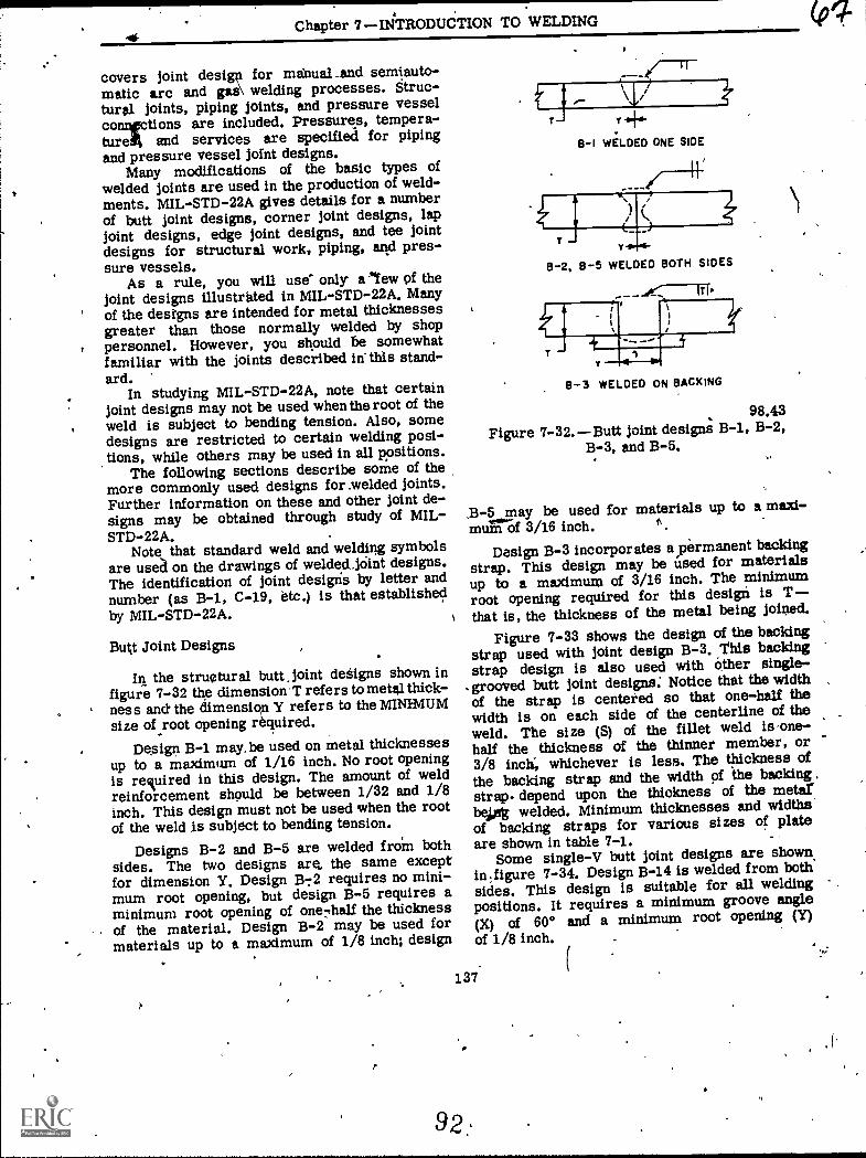
Chapter 7II4TRODUCTION TO WELDING
covers joint design for mabual and semiauto-matic arc and gas\ welding processes. Struc-tural joints, piping joints, and pressure vesselconnrctions are included. Pressures, tempera-turd% azid services are specified for pipingand pressure vessel joint designs.
Many modifications of the basic types ofwelded joints are used in the production of weld-ments. MIL-STD-22A gives details for a numberof butt joint designs, corner joint designs, lapjoint designs, edge joint designs, and tee jointdesigns for structural work, piping, and pres-sure vessels.
As a rule, you will use only efew of thejoint designs illustrated in MIL-STD-22A. Manyof the designs are intended for metal thicknessesgreater than those normally welded by shoppersonnel. However, you should be somewhatfamiliar with the joints described in'this stand-ard.
In studying MIL-STD-22A, note that certainjoint designs may not be used when theroot of theweld is subject to bending tension. Also, somedesigns are restricted to certain welding posi-dons, while others may be used in all positions.
The following sections describe some of themore commonly used designs for .welded joints.Further information on these and other joint de-signs may be obtained through study of MIL-STD-22A.
Note that standard weld and welding symbolsare usea on the drawings of welded.jOint designs.The identification of joint designs by letter andnumber (as B-1, C-19, etc.) is that establishedby MIL-STD-22A.
Butt Joint Designs
In the structural butt Joint dedigns shown infigure 7-32 the dimension T refers to metal thick-ness and the dimensiop Y refers to the MINIMUMsize of root opening required.
Degign B-1 may, be used on metal thicknessesup to a maximum of 1/16 inch. No root openingis retdred in this design. The amount of weldreinforcement should be between 1/32 and 1/8inch. This design must not be used when the rootof the weld is subject to bending tension.
Designs B-2 and B-5 are welded froin bothsides. The two designs are, the same exceptfor dimension Y. Design B-:2 requires no mini-mum root opening, but design B-5 requires aminimum root opening of one7hall the thicknessof the material. Design B-2 may be used formaterials up to a maximum of 1/8 inch; design
Y
WELDED ONE SIDE/L)
Y
8-2, 8-5 WELDED BOTH SIDES
r
8-3 WELDED ON BACKING
98.43Figure 7-32.Butt joint design B-1, B-2,
B-3, and B-5.
,B-5 may be used for materials up to a maxi-muiriOf 3/16 inch.
Design B-3 incorporates ayermanent backingstrap. This design may be used for materialsup to a maximum of 3/16 inch. The minimumroot opening required for this design is Tthat is, the thickness of the metal being joined.
Figure 7-33 shows the design of the backingstrap used with joint design B-3. This backingstrap design is also used with other single-grooved butt joint designs.' Notice that the widthof the strap is centered so that one-half thewidth is on each side of the centerline of theweld. The size (S) of the fillet weld is one-half the thickness of the thinner member, or3/8 inch, whichever is less. The thickness ofthe backing strap and the width of -the backingstrap. depend upon the thiokness of the meterbekt welded. Minimum thicknesses and widthsof backing straps for various sizes of plateare shown in table 7-1. -
Some single-V butt joint designs are shownin.figure 7-34. Design B-14 is welded from both'sides. This design is suitable for all weldingpositions. It requires a minimum groove angle
(X) of 60° and a minimum root opening (y)of 1/8 inch,
137.
9
(pq-
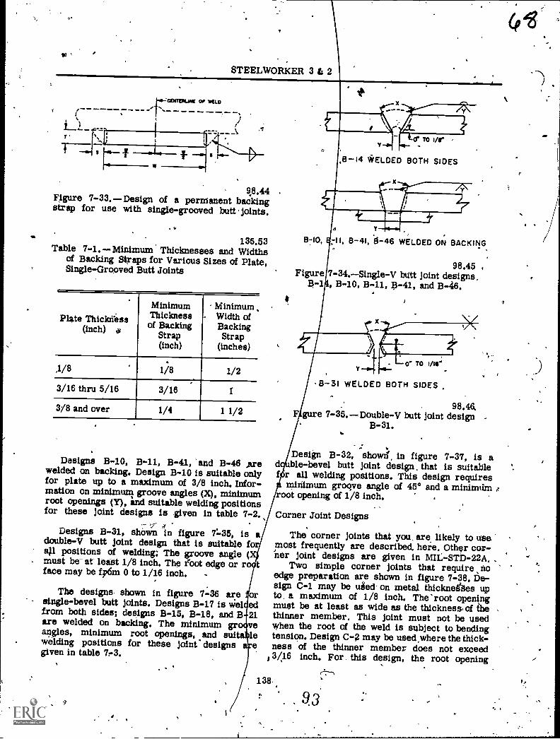
STEELWORKER 3 & 2
10-COITVIILINt OP MtL0
r M
9,8.44 .
F1gure 7-33.-1)esign of a permanent backingstrap for use with single-grooved butt joints.
135.53Table 7-1. Minimum Thicknesses and Widths
of Backing Stxaps for Various Sizes of Plate,Single-Grooved Butt Joints
Plate Thiciaress(inch) a)
MinimumThicknessof Backing
Strap(inch)
MinimumWidth ofBackingStrap
(inches)
,1/8 .
1/8 1/2
3/16 thru 5/16,
3/16 I
3/8 and over 1/4 1 1/2
Designs B-10, B-11, B-41, 'and B-46 Arewelded on backing. Design B-10 is suitable onlyfor plate up to a maximum of 3/8 inch. Infor-mation on minimum groove angles (X), minimumroot openings (Y), ind suitable welding positionsfor these joint designs is given in table 7-2.
Designs B-31, shown in figure 7.-35, is adouble-V butt joint design that is suitable fora).1 positions of welding: The groove angle (must be- at- leaSt 1/8 inch. The foot edge or r. itface may be fp6m 0 to 1/16 inch. -
The designs shown in figure 7-36 are orsingle-bevel butt joints. Designs B-17 is Wel. edfrom both sides; designs B-15, B-18, and B 21are welded on backing. The minimum gr 'yeaiigles, minimum root openings, and sui 'lewelding positions for these joint' designs egiven in table 74.
f
4B-I4 iiELDED BOTH SIDES
8710, - I, 8-41, il-46 WELDED ON BACKING
Figure98.45
7-34.Single-V butt joint designs,, B-10, B-11, B-41, and B-46.
B-31 WELDED BOTH SIDES ,
98.46,F gure 7-35.Double-V butt joint design
B-31.
Design B-32, show/ in figure 7-37, is ad ble-bevel butt joint design, that is suitablef r all welding positions. This design requires
minimum groove angle of 450 and a minimamoot opening of 1/8 inch.
Corner Joint Designs
The corner joints that you, are likely to usemost frequently are described, heie. Other cor-'ner joint designs are given in MIL-STD-22A.
Two simple corner joints that require noedge preparation are shown in figure 7-38. be-sign C-1 may be used- on metal thicknegges upto, a maximum of 1/8 inch. The 'root openingmust be at least as wide as the thickness, of 6iethinner member. This joint must not be usedwhen the root of the weld is subject to bendingtension. Design c-g may be used where the thick-ness of the thinner member (foes not exceed
13/16 inch. For , this design, the root opening
138..
9.3
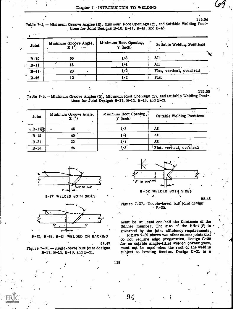
Chapter 7INTRODUCTION TO WELDING
135.54Table 7-2, Minimum Groove Angles (X), Minimum Root Openings (Y), and Suitible Welding Posi-
tions for Joint Designs B-10, B-11, B-41, and B-46
Joint Minimum Groove Angle,X (°)
,
Minimum Root Opening,Y (inch)
:Suitable Welding Positions,
.9-10 . 60 . 1/8
, . ..
All ,
B-11 45 1/4 All
B-41' 20 , 112 Flat, vertical, overhead
9-46 12 1/2 Flat
135.55Table 7-3. Minimum'Groove Angles (X), Minimum Root Openings (Y), and Suitable Welding Posi-
tions for-Joint Designs B-17, B-15, B-18, and B-21
Joint Minimum Groove Angle,
,
Minimum Root Opening,...
.
Suitable Welding Positions
t B-173 --- 45 1/8 All
'B-15 45 1/4 All
B-21 35 , 3/8r
All .
. B-18 25 3/8 1 Flat, vertical, oveihead,
-
,
8-17 WELDED BOTH SIDES
8-15, 8-18, 8-21 WELDED ON BACKING
. 98.47Figure 7-36.Single-bevel butt joint designs
B-17, B-15, B-18, and B-21.
8=32 WELDED !WTI, SIDES
98.48Figure 7-37.Double-bevel butt- joint design'
B-32.
must be at least one-half the thickness of thethinner member. The size of .the fillet (5) isgoverned by the 'joint efficiency requirements-.
Figure 7-39 shows two other corner joints thaido not require edge preparation. Design C-.20for an oupide single-fillet welded corner joint,must not be used when the root of the weld issubject to bending tension. Design C-21 is a
139
94
VI
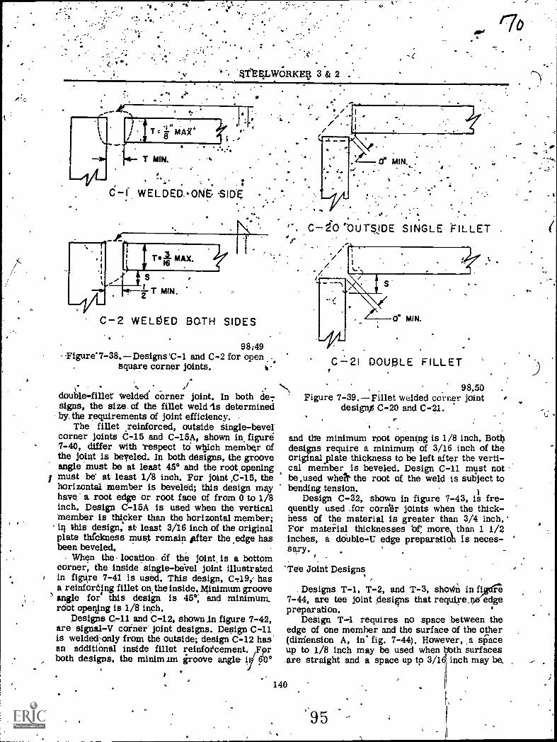
-t
Aro
d--I WELDED..ON. SID2.
I
C-2 WELDED BOTH SIDES
98;49Figure 7-38.Designs'C-1 and C-2 for open
square corn,er joints. t-.
x- 1/4,double-fillet Welded dinner joint. In both de-;signs, the size_ of the fillet weld is determinedby,the requirements of joint efficiency. ,
The fillet reinforced, outside Single-bevelcorner joints 6-15 and C-15A, shown in figure7-40, differ with 'respect td wigch member ofthe joint is beveled. In both designs, the grooveangle must be at least 450 -and the root,openingmust be at least 1/8 inch. For joint ,C-15, thehorizontal member is beveled; this design mayhave a root edge or root face of from 0 to 1/8inch. Design C-15A is used when the verticalmember is thicker than the horizontal member;in, this design, at: least 3/16 inch of the originalplate thfckness must remain itfter the ,edge hasbeen beveled.
When the location- of the joint, is a bottomcorner, the inside single-bevel joint illustratedin figure 7-41 is used. This design, C719,- hasa reinforólng fillet on the inside. Minimum grooveangle for this design is 45°, and minimum,.rdot opelng is 1/8 inch.
Designs C-11 and C-12, shown In figure '7 - 42 ,are signal-V corner joint designs. Design C-11is welded:only from the outside; design.C-12 hasan additiOnal inside fillet reinfotcement. Fprboth designs, the minim.= irooVe angle
c-iCOUTSJDE SINGLE FILLET .
0" MIN.
,CL2I DOUBLE FILLET
98.50Figure 7-39. Fillet welded corner joint
desig0 C-20 and C=21.
and the minimum root opening is 1/8 inch. Bathdesigns require a minimum of 3/16 inch of theoriginalylate thickness to be left after the verti-cal member is beveled. Design C-11 must notbe ,used whek the root of the weld is sui3ject tobending tension.
Design C-32, shown in figure 7-43, is fre-quently used , for corifer joints when the thick-hess of the material is greater than 3/4 inch.For mateiial thicknesses 'of; more than 1 1/2inches, a double-U edge preparatioh is neces-sary.
'Tee Joint Designs
Designs T-1, T-2, and T-3, shollin in fiW1 re7-44, are tee joint desies that require. edgepreparation.
DeSign T-1 requires no space between theedge of one member and the surface of the other(dizriension A, in° fig. 7-44), However, a si3aceup to 1/8 inch may be used when bbth surfaces,are straight and a space up to 3/16 inch may be,
140
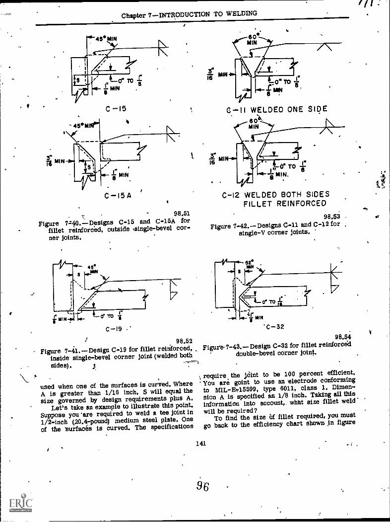
Chapter 7INTEODUCTION TO WELDING
98.51
Figure 7z40.Designs C-15 and C-15A forfillet reinforced, outside ,sing1e-bevel cor-ner joints.
C-19
98.52Figure 7-41. Design C-19 for fillet reinforced,
inside single-bevel corner joint (welded bothsides).
used when one of the surfaces is curved. WhereA is greater than 1/16 inch, S will equal thesize governed by design requirements plus A.
Let's take an example to illustrate this point.Suppose you 'are required to weld a tee joint in1/2-inch (20.47pound) medium steel plate. Oneof the 'surfaces is curved. The specifications
3"
C 11 WELDED ONE SIPE
MIN
C-12 WELDED BOTH SIDESFILLET REINFORCED
98.53Figure 7-42. --Designs C-11 and C-12 for
single-V corner joints.
C-3298.54
Figure 7-43.Design C-32 for fillet reinforceddouble-bevel corner joint.
require the jOint to be 100 percent efficient.You are goint to use an 'electrode conformingto MIL-Ev15599, type 6011, class L. Dimen-sion A is specified as 1/8 inch. Taking all thisinformation into account,. what size fillet weldwill be required?
To find the size Of fillet required, you mustgo back to the efficiency chart shown in figure
141
96 .
f
1
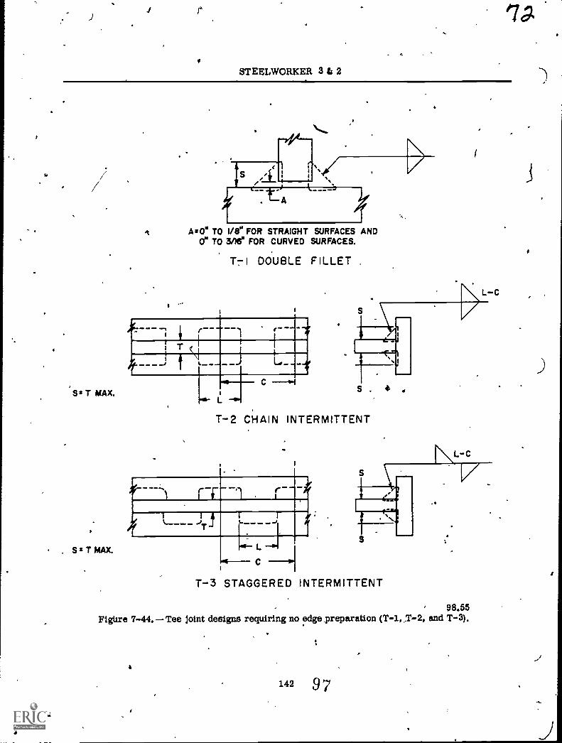
)
STEELWORKER 3 ts 2
'Ss T MAX.
I
. . S* T MAX.
,:.
A toe TO 1/8" FOR STRAIGHT SURFACES AND0" TO me FOR CURVED SURFACES.
T7I DOUBLE FILLET ,
I
11M111111=1111
EIIIIIAIIIIIIIIMIIII,L
T-2 CHAIN INTERMITTENT
s
i
S .
..
4 4
T-3 STAGGERED INTERMITTENT
' 98.55FigUre 7-44. Tee joint designs requiring no edge preparation (T-1,7-2, and T-3).
i
e
:
142 97
,
,
#
:
M.
J
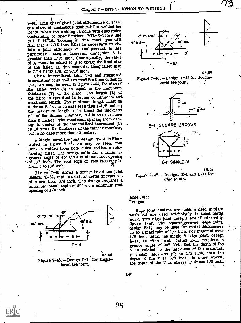
Chapter 77INTRODUCTION TO WELDING
7-31. This chart (Week joint efficiencies of vari-ous sizes of continuous double-fillet welded teejoints, when the welding' is done with 'electrodesconforming to Specifications HIL-E-15599 andMIL-E-1673,5. LoOking at this chart, you svillfind that a 7/16-inch fillet is necessary to ob-tain a joint efficiency of 100 percent. In thisparticular example, however, dimepsion A isgreater than 1/16 inch. Consequently, the valueot A must be added to to obtain the final sizect the fillet. In this example, then; fillet sizeis 7/16 PLUS 1/8, or '9/16 inch.
Chain intermittent joint .T-2 and staggeredintermittent joint T-3 are modifications of designT-1. As may be- seen in figure 7-44, the size of
.,the fillet weld (S) is equal to the maximumthickness (T) of the plate. Th length (L) ofthe fillet is specified in terms of minimum and,maximum length. The minimum length must be8 times 5, but in no case less than 1-1/2 inches;the maximum length is 16 times the thickness(T) of the thinner member, tut in no case morethan 6 inches. The maximum epacing from cen-ter to center of the intermittent increment (C)is 16 times the thickness of the thinner member,but in no case more than 12 inches.
A /single-bevel tee joint design, T-14, is illus-trated in figure 7-45. As may be seen, thisjoint is welded from both sides and hes a rein-forcing fillet. The design calls for a minimumgroove angle of 45' and a minimum root opening'of 1/8 inch. The root edge or root face ngy befrom 0 to 1/8 inch.
Figure -7-46 shows a double-bevel tee jointdesign, T-32, that is used for metal thicknesses.of more than 3/4 inch. The design requires aminimum bevel angle of 52' and a minimum rootopening of 1/8 inch.
T-I4
98.56Figure 7-45. Design T-14* for single-
bevel tee joint.
98
T - 32
98.57Figure 7-46.Design T-32 for double-
beVel tee joint. ' /
EI SQUARE GROOVEce
E-11.SINGLEV
98.58Figure 7-47. Designs E-1 and E-11 for
edge joints.
s-
.10
Edge JointDesigns
Edge joint designs are seldom used in platework but are used extensively in -sheet metalwork. Two edge joint designs are illustrated infigure 7-47. The 'squaretgrooved edge joinf,design E-1; may be used for metal thicknessesup to a maximtim of 1/8 inch. For material over1/8 inch thick, the single-V edge joint, designE-11, is often used. Design E-11 requires agroove angle of 90°. Note that the depth of theV is related to the thickness of the material.If metal( thickness (T) is 1/2 inch, then thedepth of the V is 3/8 inchin other words,the depth of the V is always T rainus 1/8 inch.
143
(7
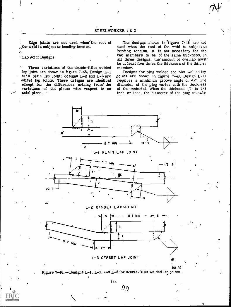
1
1- ,
. oh
STEELWORKER 3 & 2 '
Edge joints are not used whejthe root of.the weld is subject to bending tension..,.
'-'Lap Joint Designs
Three variations of the double-fillet weldedlap joint are shown in figure 7-48. Design L-1Isla plain lap joint; designs L-2 and L-3 are-offset lap joints. These designs are ideriticalexcept for the differences arising from' thevariations of the plates with respect to an,./ axial plane.
,
i
,
The desigas shown in °figure 7-48 are notused when the root of the weld is subject tobending tension. It is not necestary for thetvio members to be of the same thickness. Inall three designs, the amount of overlap must'be at least five times the thickness-of the thinnermember. .
Designs for plug welded and slot v.elded lapJoints are shown in figure 7-49. Design L-11requires a minimum groove angle of 450 . Thediameter of the plug varies with the tiucknessof the material. When the thickness (T) is 1/8inch or less, the diameter of the plug inust-be
T I
,..
5 T MIN ----Ili
L-I PLAIN LAP JOINT
.4--- S
,
L-2 OFFSET LAP.JOINT,
,
L--3 OFFSET LAP JOINT it,
98.59FJEcure 7-48.Designs L-1, L-2, and L.-3 for double-fillet welded lap joints.
\144
99, ,
A
,
,..
4
...
,
E
r
I
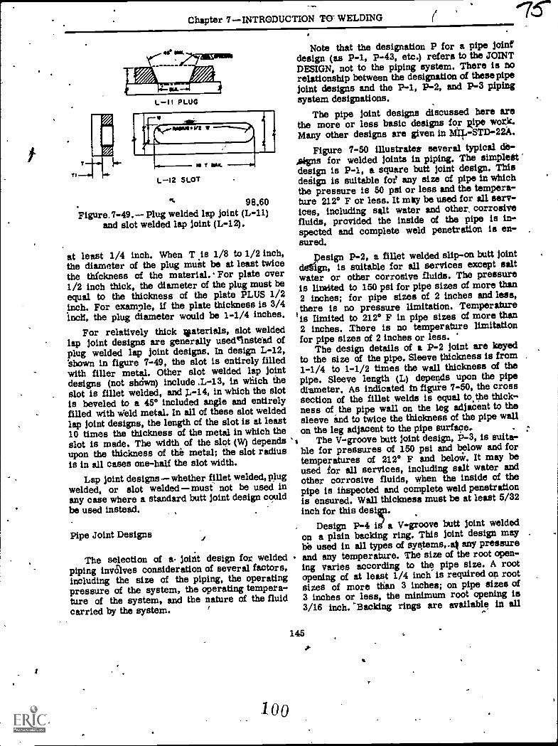
Chapter 7INTRODUCTION TWELDING
TI
L-11 PLUG
MOINUOWS W
111 T X.
L-I2 SLOT
98.60Figure , 7-49. Plug welded lap joint (L-11)
and slot welded lap joint (L-12).
at least 1/4 inch. When T .is 1/8 to 1/2 inch,the diameter of the plug must be at least twicethe thfckness of the material. For plate over1/2 inch thick, the diameter of the plug must beequal to the thickness of the plate PLUS 1/2inch. For example, if the plate thickness is 3/4incti, the plug diameter would be 1-1/4 inches.
For relatively thick waterials, slot weldedlap joint designs are generally usedeinste'ad ofplug welded lap joint designs. In design L-12,shown in figure 7-49, the slot is entirely filledwith filler metal. Other slot welded lap jointdesigns (not shdwn) include ,L-13, in whiich theslot is fillet welded, and J.,-14, in which the slotis beveled to a 45° included angle and entirelyfilled with Weld metal. In all of these slot weldedlap joint designs, the length of the slot is at least10 times the thickness of the metal in which theslot is made. The width of the slot (W) dependsupon the thickness of the metal; the slot radiusis in all cases one-half the slot width.
Lap joint designswhether fillet welded, plugwelded, or slot welded must not be used inany case where a standard butt joint design couldbe used instead.
Pipe Joint Designs
The selection of a joitit design for weldedpiping invaves consideration of several factors,including the size of the piping, the operatingpressure of the system, the operating tempera-ture of the system, and the nature of the fluidcarried by the system.
100
Note that the designation P for a pipe joinfdesign (as P-1, P-43, etc.) refers to the JOINTDESIGN, not to the piping system. There is norelationship between the designation of these pipejoint designs and the P-1, P-2, and P-3 pipingsystem designations.
The pipe joint designs discussed here arethe more or less basic designs for Ripe work.Many other designs are given in MIL-STD-22.
Figure 7-50 illustrates several typical de-Awns for welded joints in piping. The simplestdesign is P-1, a square butt joint design. Thisdegign is suitable foi any size of pipe in whichthe pressure is 50 psi or less and the tempera-ture 212° F or less. It may be used for all serv-ices, including salt water and other, corrosivefluids, provided the inside of the pipe is in-spected and complete weld penetration is en-sured.
pesign P-2, a fillet welded slip-on butt jointdefign, is suitable for all services except saltwater or other corrosive fluids. The pressureis limited to 150 psi for pipe sizes of more than2 inches; for pipe sizes of 2 inches and less,there is no pressure limitation. Temperatureis limited to 212° F in pipe sizes of more than2 inches. There is no temperature limitationfor pipe sizes of 2 inches or less.
The design details of a P-2 joint are keyedto the size of the pipe. Sleeve thickness is from1-1/4 to 1-1/2 times the wall thickness of thepipe. Sleeve length (L) depends upon the pipediameter. As indicated in figure 7-50, the crosssection of the fillet welds is equal to.the thick-ness of, the pipe wall on the leg adjacent to thesleeve and to twice the thickness of the pipe wallon the Ieg adjacent to the pipe surface. :
'$ The V-groove butt joint design, P-3, is suita-ble for pressures of 150 psi and below and fortemperatures of 212° F and below. It may beused tor all services, including salt water andother corrosive fluids, when the inside of thepipe is inspected and complete weld penetrationis ensured. Wall thickness must be at least 5/32inch for this desiet.
Design P-4 id a V-groove butt Joint weldedon a plain backing ring. This joint design maybe used in all types of systems, Ait any pressureand any temperature. The size of the root open-ing varies according to the pipe size. A rootopening of at least 1/4 inch is required op rootsizes of more than 3 inches; on pipe sizes of3 inches or less, the minimum root opening is3/16 inch. "Backing rings are available in all
145
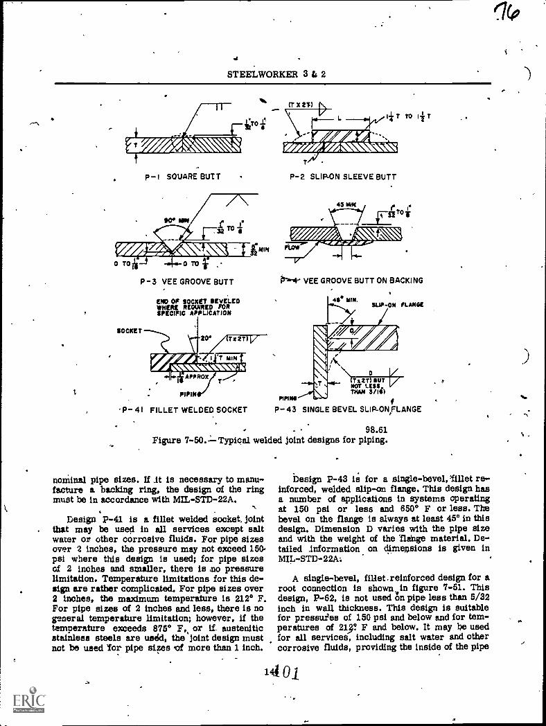
"-^
_
STEELWORKER 3 & 2
ZWAl&p-i SQUARE BUTT
P-3 VEE GROOVE BUTT
SOCKET
ENO OF SOCKET BEVELEDWHERE REQUIRED FORSPECIFIC APPLICATION
1 I
IV\ 11i
x 2T
APPROX
PIPIN
P- 41 FILLET WELDED SOCKET
CT X 2T)
T TO I T
P-2 SLIP-ON SLEEVE BUTT
45 MIK
4.
PIPINS
P-43 SINGLE BEVEL SLIP-ONILANGE
41/40"..7.040"
VEE GROOVE BUTT ON BACKING
SUP-ON FLOM41° MIN.
1\0 /
(Ts 2T) BUT /ROT LISS,IMAM 3/10)
. . 98.61Figure 7-50.=Typical welded joint designs for piping.
nominal pipe sizes. If it is necessary to manu-facture a backing ring, the design of the ringmust be in accordance with MIL-STD-22A.
Design P-41. is a fillet welded socket. jointthat may be used in all services except saltwater or other corrosive fluids. For pipe sizesover 2 inches, the pressure may not exceed 150..psi where this design is used; for pipe sizesof 2 inches and smaller, there is no pressurelimitation. Temperature limitations for this de-sign are rather complicated. For pipe sizes over2 inches, the maximum temperature is 212° F.For pipe sizes of 2 inches and less, there is nogeneral temperature limitation; however, if thetemperature exceeds 875° F,, or if. austeniticstainless steels are usid, the joint design mustnot be used 'for pipe siF.es vf more than 1 inch.
Design P-43 is for a single-bevel,'fillet re-inforced, welded slip-on flange. This design hasa number of applications in systems operatingat 150 psi or less and 650° F or less. Thebevel on the flange is always at least 450 in thisdesign. Dimension D varies with the pipe sizeand with the weight of the 'flange materiel. De-tailed Information on dimensions is given inMIL-STD-22A;
A single-bevel, fillet.reinforced design for aroot connection is shown. in figure 7-51. Thisdesign, P-62, is not used f.in pipe less than 5/32inch in wall thickness. This design is suitablefor pressuies of 150 psi and below and for tem-peratures of 213? F and below. It may be usedfor all services, including salt water and otborcorrosive fluids, providing the inside of the pipe
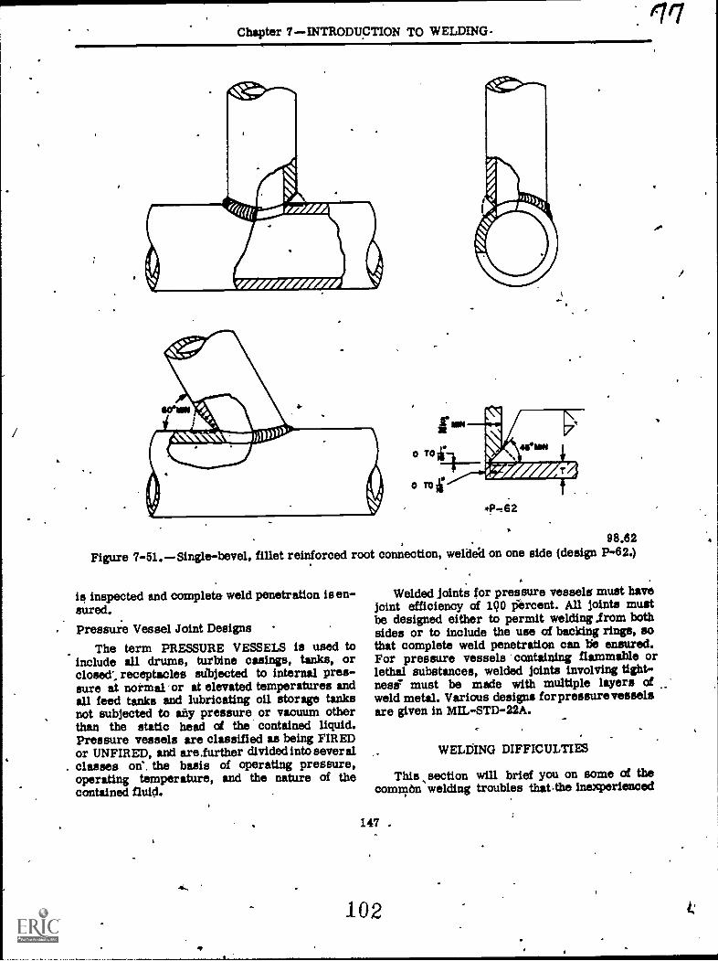
Chapter 7 INTRODUCTION TO WELDING-
A-.t62
98.62
Figure 7-51. Single-bevel, fillet reinforced root connection, weldea on one side (design P-62.)
is inspected and complete weld penetration is en-sured.Pressure Vessel Joint Designs
The term PRESSURE VESSELS is used toinclude all drums, turbine casings, tanks, orclosed, receptacles suljected to internal pres-sure at normal -or at elevated temperatures andall feed tanks and lubricating oil storage tanksnot subjected to any pressure or vacuum otherthan the static head of the contained liquid.Pressure vessels are classified as being FIREDor UNFIRED, and are iurther divided into sever alclasses on', the basis of operating pressure,operating temperature, and the nature of thecontained fluid.
Welded Joints for pressure vessels must havejoint efficiency of 190 iercent. All joints mustbe designed either to permit welding ,from bothsides or to include the use of backing rings, sothat complete weld penetration can be ensured.For pressure vessels containing flammable orlethal substances, welded joints involving tight-ness"- must be made with multiple layers ofweld metal. Various designs forpressure vesselsare given in MIL-STD-22A.
WELOING DIFFICULTIES
This section will brief you on some of thecomniton welding troubles that.the inexperienced
147 ,
102
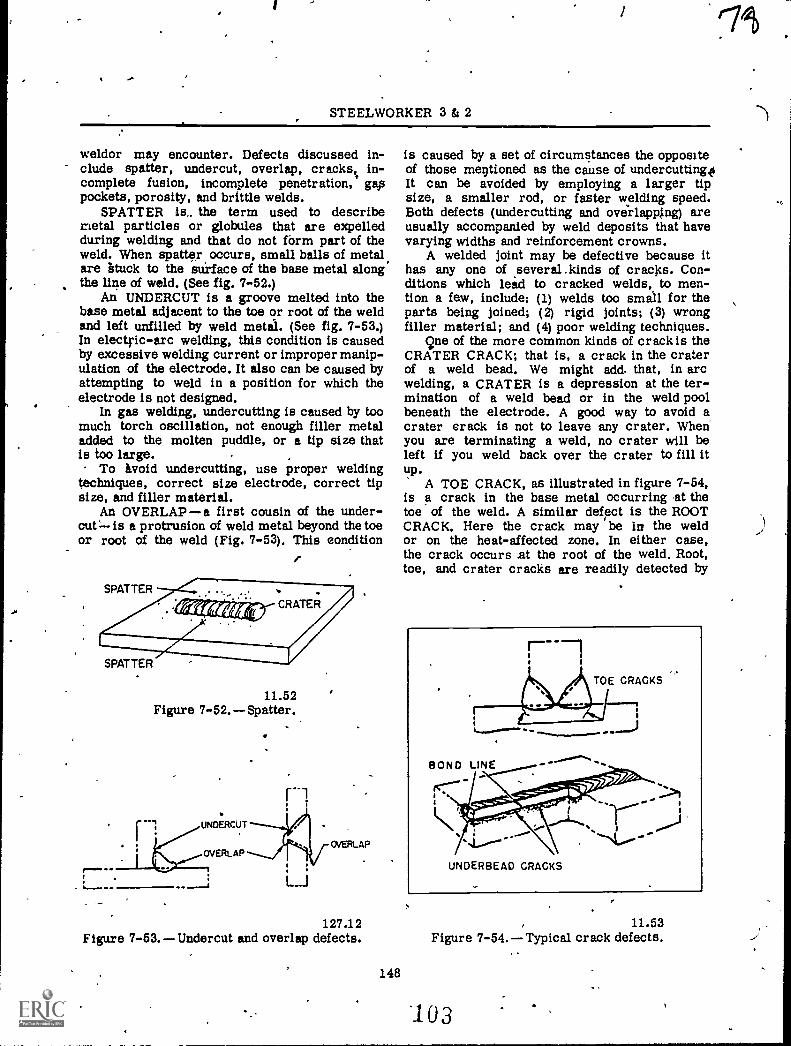
STEELWORKER 3 & 2
weldor may encounter. Defects discussed in-clude spatter, undercut, overlap, cracks% in-complete fusion, incomplete penetration, gappockets, porosity, and brittle welds.
SPATTER is.. the term used to describemetal particles or globules that are expelledduring welding and that do not form part of theweld. When spatter occurs, small balls of metal.are Stuck to the Surface of the base metal alongthe line of weld. (See fig. 7-52.)
Ab UNDERCUT is a groove melted into thebase metal adjacent to the toe or root of the weldand left unfilled by weld metal. (See fig. 7-53.)In electfic-arc welding, this condition is causedby excessive welding current or improper manip-ulation of the electrode. It also can be caused byattempting to weld in a position for which theelectrode is not designed.
In gas welding, undercutting is caused by toomuch torch oscillation, not enough filler metaladded to the molten puddle, or a tip size thatis too large.
To ivoid undercutting, use proper weldingtechniques, correct size electrode, correct tipsize, and filler material.
An OVERLAPa first cousin of the under-cut= is a protrusion of weld metal beyond the toeor root of the weld (Fig. 7-53). This eondition
I
11.52Figure 7-52. Spatter.
OVERLAP
127.12Figure 7-53. Undercut and overlap defects.
148
is caused by a set of circumstances the oppositeof those mentioned as the cause of undercutting0It can be avoided by employing a larger tipsize, a smaller rod, or faster welding speed.Both defects (undercutting and overlapping) areusually accompanied by weld deposits that havevarying widths and reinforcement crowns.
A welded joint may be defective because ithas any one of .several.kinds of cracks. Con-ditions which lead to cracked welds, to men-tion a few, include; (1) welds too small for theparts being joined; (2) rigid joints; (3) wrongfiller material; and (4) poor welding techniques,
9ne of the more common kinds of crack is theCRATER CRACK; that is, a crack in the craterof a weld bead. We might add. that, in arcwelding, a CRATER is a depression at the ter-mination of a weld bead or in the weld poolbeneath the electrode. A good way to avoid acrater crack is not to leave any crater. Whenyou are terminating a weld, no crater will beleft if you weld back over the crater to fill itup.
A TOE CRACK, as illustrated in figure 7-54,is a crack in the base metal occurring ,at thetoe of the weld. A similar defect is the ROOTCRACK. Here the crack may be hi the weldor on the heat-affected zone. In either case,the crack occurs nt the root of the weld. Root,toe, and crater cracks are readily detected by
11.53Figure 7-54. Typical crack defects.
3
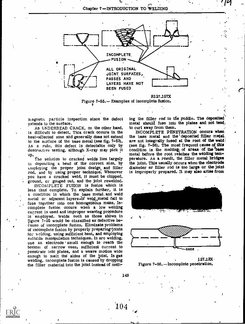
.
Chapter 7INTRODUCTION TO 'WELDINGrig
.. .
40.
INCOMPLETE.FUS I ON
ALL ORIGINALJOINT SURFAtES,PASSES ANDLAYERS HAVE NOTBEEN FUSED
R127.157XFigur: 7-55. Examples of incomplete fusion.
magnetic particle inspection since the defectextends to the surface.
An UNDERBEAD CRACK, on the other hand,is difficult to detect. Thia crack occurs in theheat-affected zone and generally does not extendto the surface of the base metal (see fig. 7-53).As a rule, this defect is detectable only bydestructive testing, although X-ray may pick itup.
f he solution to cracked welds lies largelyin depositing a bead of the correct size, bysrupluying the proper joint design, and fillerrod, and by using proper technique. Wheneveryou have a cracked weld, it must be chipped,ground, or gouged out, and the joint rewelded.
INCOMPLETE FUSION is fusion which ialess than complete. To explain further, it isa condition in which the base metal. and weldmetal or adjacent layers:of we4smetal fail tofuse together into one homogeneous miss. In-complete fusion occurs when a low weldingcurrent is used and improper weaving procedureis employed. Welds such as those shown infigure 7-55 would be- classified as'defective be-cause of incomplete fusion. Eliminate problemsof incomplete fusion by properly preparinglointsfor welding, using sufficient heat, and employingsuitable manipulation techniques. In arc welding,use an electrode small enough to reach thebottom of narrow vees, sufficient current topenetrate into plates, and a weave motion wideenough to melt the sides of the loint. In gaswelding, incomplete fusion is caused by droppingthe filler material into the joint instead of melt-
149
, 104
:
ing the filler rod in die puddle. The depositedmetal should fuse into the plates and not tend .to curl away from them.
INCOMPLETE PENETRATION Occurs whenthe base metal and the deposited filler metdare not integrally fused at the root Of the weld:(see fig. 7-56). The most-frequent cause di thiscondition is the meltingi of areas of the abasemetal before the root reaches the welding tem-perature. As a result, the filler metal bridgesthe joint. This usually occurs whenthe electrodediameter or filler rod is too large or the Jointis improperly prepared. It may also arise from
k
12.7.13XFigure 7-56.Incomplete penetration.
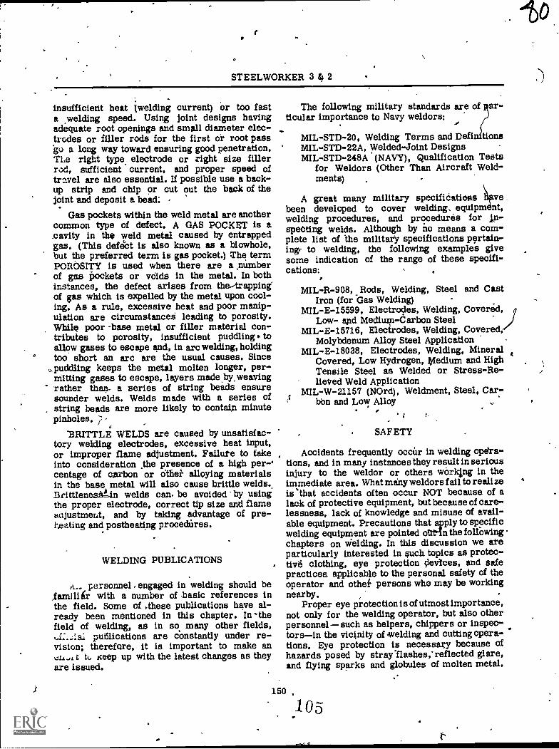
STEELWORKER 3 4 2
insufficient heat twelding current) Or too fasta welding speed. Using joint designs havingadequate root openings and small diameter elec-trodes or filler rods for the first or root pass'go a long way toward ensuring good penetration.The right type, electrode or right size filler
sufficient current, and proper speed oftravel are also essential. If possible use a back-up strip and chip or cut out the back of thejoint and deposit a bead.
Gas pockets within the weld metal are anothercommon type of defect. A GAS POCKET is a.cayity in the weld metal caused by entrappedgas. (This defect is also known as a blowhole,but the preferred term is gas pocket.) The termPOROSITY is used when there are a al:umberof gas imckets or voids in the metal. In bothinstances, the defect arises from the--trappingof gas which is expelled by the metal upon cool-ing. As a rule, excessive heat and poor manip-ulation are circumstances leading to porosity.While poor -base metal or filler material con-tributes to porosity, insufficient puddling toallow gases to escape and, in arc welding, holdingtoo short an arc are the usual causes. Since
.puddling keeps the metal molten longer, per-raiding gases to escape, layers made,by.weavingrather than.. a series of string beads ensuresounder welds. Welds made with a series ofstring beads are more likely to contain minutepinholes. 2 -
'BRITTLE WELDS are caused by unsatisfac-tory welding electrodes, excessive heat input,or improper flame adjustment. Failure to takeinto consideration ,the presence of a high per-^centage of carbon or dthei alloying materialsin the base metal will also cause brittle welds..Britt/enesg-in welds can. be avoided by usingthe proper electrode, correct tip size and flameunjustment, and by taking advantage of pre-heating and postheating procedures.
WELDING PUBLICATIONS
personnel engaged in welding should be,farniliir with a number of basic references inthe field. Some of .these publications have al-ready been mentioned in this chapter. In -thefield of welding, as in sR many other fields,
putilications are constantly under re-vision; therefore, it is important to make an
t. tt, seep up with the latest changes as theyare issued.
The following military standards are of ar-ticular importance to Navy weldors:
MIL-STD-20, Welding Terms and Definftlon sMIL-STD-22A, Welded-Joint DesignsMIL-STD-248A (NAVY), Qualification Tests
for Weldors (Other Than Aircraft Weld-ments)
aA great many military specifidatioas vebeen developed to cover welding, equipm nt,welding procedures, and procedures for jp-speCting welds. Although by ho means a com-plete list of the military specifications pertain-ing( to welding, the following examples givesome indication of the range of these specifi-cations:
MIL-R-908, Rods, Welding, Steel and CastIron (for Gas Welding) -
MIL-E-15599, Electrodes, Welding, Covered,Low- and Medium-darbon Steel
MIL-E-15716, Electrodes, Welding, Covered/Molybdenum Alloy Steel Application
MIL-E-18038, Electrodes, Welding, MineralCovered, Low Hydrogen, Medium and HighTensile Steel as Welded or Stress-Re-lieVed Weld Application
MIL-W-21157 (NOrd), Weldment, Steel, Car-,bon and Lost.: Alloy
* .
SAFETY
Accidents frequently occUr in welding opera-tions, and in many instances they result in seriousinjury to the weldor or others wórking in theimmediate area. What many weldors f ail to reali zeis 'that accidents often occur NOT because of alack of protective equipment, but because of care-lessness, lack of knowledge and misuse of avail-able equipment. Precautions that apply to specificwelding equipment are pointed oUtbin the folfowingchapters on Welding. In this discussion we areparticularly interested in such topics as protec-tivd clothing, eye protection devtces, and safepractices applicable to the personal safety of theoperator and othef persons who may be workingnearby.
Proper eye protec tion is of utmost importance,not only for the welding operator, but also otherpersonnelsuch as helpers, chippers or inspec-torsin the vicjnity of welding and cutting opera-tions. Eye protection is necessary because ofhazards posed by stray Ilashes,'reflected glare,and flying sparks and globules of molten metal.
150
105
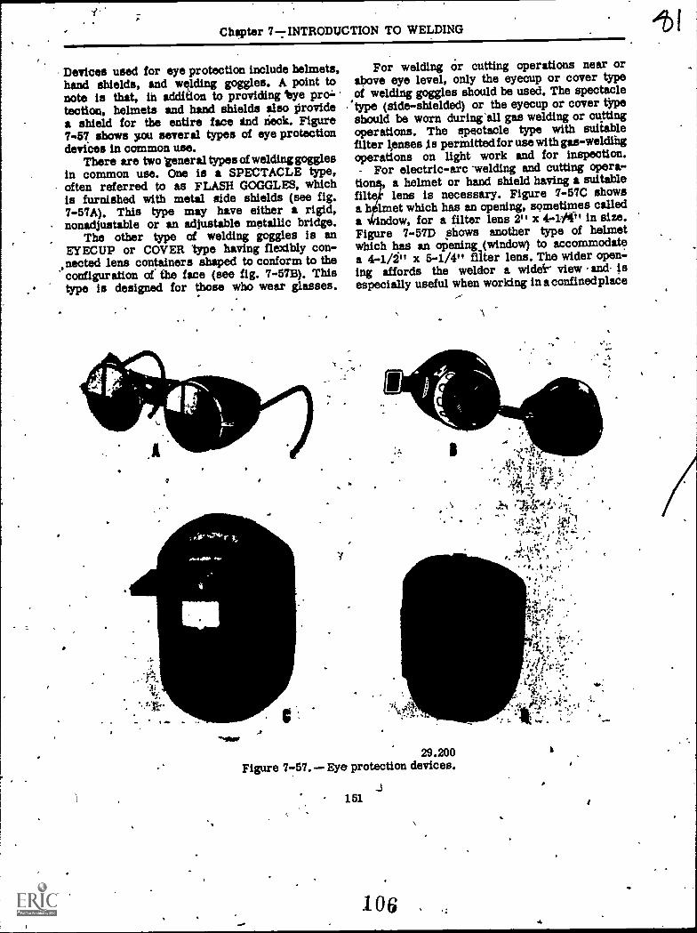
Chapter 77INTRODUCTION TO WELDING
Devices used for eye protection include helmets,hand shields, and welding goggles. A point tonote is that, in addition to providing bye protection, helmets and hand shields also providea shield for the entire face ind deck. Figure7-57 shows you several types of eye protectiondevices in common use.
There are two 'general types of welding gogglesin common use. One is a SPECTACLE type,often referred to as FLASH GOGGLES, whichis furnished with metal side shields (see fig.7-57A). This type may have either a rigid,nonadjustable or an adjustable metallic bridge.
, The other type of welding goggles is anEYECUP or COVER type having flexibly con-nected lens containers shaped to conform to theconfiguration of the face (see fig. 7-5713.). Thistype is designed for those who wear glasses.
P
.4.
'moor
For welding Or cutting operations near orabove eye level, only the eyecup or cover typeof welding goggles should be used, The spectacle
"type (side-shielded) or the eyecup or cover tYpeshould be worn during'all gas welding or cuttingoperations. The spectacle type with suitablefilter Oases Is permitted for use with gas-weldingoperations on light work and for inspection.
For electric-arc .welding and cutting opera-tio , a helmet or hand shield having a suitableflltefr lone is necessary. Figure 7-57C showsa hØlrnet which has an opening, sometimes calleda ow, for a filter lens 2" x 4-r/41, in size.Figure 7-57D shows another type of helmetwhich has an opening (window) to accommodatea 4-1/2" x 5-1/4" filter lens. The wider open:-ing affords the weldor a widei- view and isespecially useful when working in aconfinedplace
29.200Figure 7-57. Eye protection devices.
151
106 .
,
..`
it!.
3.
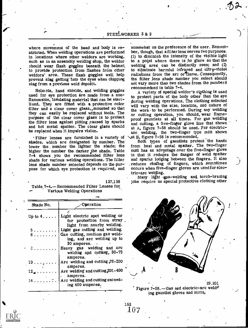
STEELWORKER 3 & 2
where movement of the head and body is re-stricted. When welding operations are performedin locations where other weldors are working,such as in an assembly welding shop, the weldorshould wear flash goggles beneath the helmetto provide protection from flashes frOm otherweldors' arcs. These flash goggles well helpprevent slag getting-Into the eyes when chippingslag from a previous weld depo6it.
Helmets, hand shields, and welding gogglesused for eye protection are made from a non-flammable, insulating material that can be steri-lized. They are fitted with a protective colorfilter and a clear cover glass,,,mounted so thatthey can easily be replaced without tools. Thepurpose of the clear cover glass is to protectthe filter lens against pitting ,caused by sparksand hot metal spatter. The clear glass shouldbe replaced when it impairs vision.
Filter lenses are furnished in a variety of,shades, which are designated by number. Thelower the number the lighter the shade; thehigher the number the darker othe shade. Table7-4 shows you the recommended filter legsshade for various welding operations. The filterlens shade number selected depends on the pur-pose for which eye protection is required, and
127.158Table,7-4. Recbmmended Filter Lenses for
Various Welding Operations
Shade No.
Up to 4
56
2,
10
12.,
14
/Operation
Light electric spot welding orfor protection from straylight from nearby welding.
Light gas cutting and welding.Gas cutting, medium gas weld-
ing, and arc welding up to30 amperes. -
Heavy gas welding and arcwelding and cutting, 30-75amperes.
Arc welding and cutting ,76-200aniperes.
Arc welding and cutting,201-400. amperes.Arc welding and cutting exceed-
ing 400 amperes
somewhat on the preference of the user. Remelt-ber, though, that a filter lens serves two purposes:(1) to diminish the intensity of the visible lightto a point where there is .ho 'glare so that thewelding area, can be distinctly seen; and (2)to eliminate harmful infrared and ultrrvioletradiations from the arc ortame. Consequently,the filter lens shade number you select shouldnot vary more than two shades from the pumbertrecommedned in table 7-4.
A variety of special weldor's ckothing is usedto protect parts of the body other than the eyeduring welding operations. The clothing selectedwill vary with the size, locatiOn, and nature ofthe work- to be performed. During any weldingor cutting operation, you should, wear flame-proof gauntlets at all times: For gas weldingand cutting, a five-finger glove like that shownat A, figure 7-58 should be used. For electric-arc.. welding, the two-finger type mitt shown
\at B, figure 7-58 is recommended.Both types of gauntlets protect the hands
from heat and metal spatter. The two-fingermitt has an advantage over the five-finger glovein that it reduc,es the danger of weld spatterand sparks lodging between the fingers. It also
_ reduces chafing of fingers, which sometimesoccurs when five-finger gloves are used for elec-tric-arc welding.
Many , light las-welding and_ torch-brazingjobs require no special protective clothing other
29.201Figure 7-58. Gas and electric-arc weld=
ing gauntlet gloves and mittk.
152
0 7
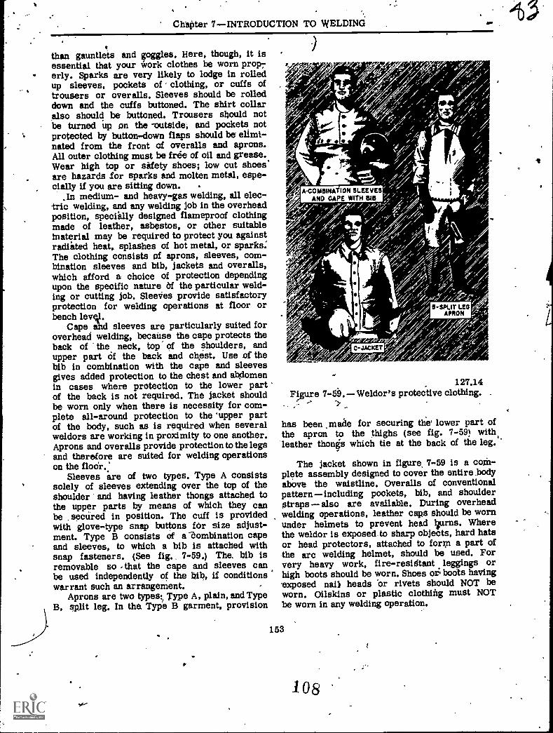
-
,
ChaPter 7 INTRODUCTION TO WELDINd
than gauntlets and goggles. Here, though, it isessential that your irork clothes be worn prop7erly. Sparks are very likely to lodge in rolledup sleeves, pockets of clothing, or cuffs oftrousers or overalls. Sleeves should be rolleddown and the cuffs buttoned. The shirt collaralso should be buttoned. Trousers should notbe turned up on the -outside, and pockets notprotected by button-down flaps should be elimi-nated from the front of overalls and aprons.All outer clothing must be free of oil and grease.Wear high top or sitfety shoes; low cut shoes'are hazards for sparks and molten metal, espe-cially if you are siding down.
In medium- and heavy-gas welding, all elec-tric welding, and any welding job in the overheadposition, speciilly designed flameproof clothingmade of leather, asbestos, or other suitableinaterial may be required to protect you againstradiated heat, splashes of hot metal, or sparks:The clothing consists of aprons, sleeves, com-bination sleeves and bib, jackets and overalls,which afford a choice of protection dependingupon the specific nature Of the particular weld-ing or cutting job. Sleeves provide satisfactoryprotection for welding operations at floor orbench levstl.
Cape abd sleeves are particularly suited foroverhead welding, because the cape protects theback of the neck, top of the shoulders, andupper part Of the back and chest. Use a thebib in combination with the cape and sleevesgives added protection to the chest and abdomenin cases where protection to the lower partof the back is not required. The jacket shouldbe worn only when there is necessity for com-plete all-around protection to the 'upper partof the body, such u is required when severalweldors are working in proximity to one another.Aprons and overalls provide protection to the legsand therefore are suited for welding operationson the floOr.;
Sleeves are of two types. Type A consistssolely of sleeves extending over the top of theshoulder and having leather thongs attached tothe upper parts by means of which they canbe secured in position. The cuff is providedwith glove-type snap buttons for size adjust-ment. Type B consists of a "Zombination capeand sleeves, to which a bib is attached withsnap fasteners. (See fig. 7-59.) The. bib isremovable so that the cape and sleeves canbe used independently of the hib, if conditionswarrant such an arrangement.
Aprons are two types:1 Type A, plain, and TypeB, p1it leg. In the Type B garment, provision
127.14Figure Weldor's protective clothing. .
has been ,made for securing the lower part ofthe apron to the thighs (see fig. 7-59) with.'leather thong's which tie at the back of the leg.
The jacket shown in figure, 7-59 is a coM-plete assembly designed to cover the entire _bodyabove the waistline. Overalls of conventionalpatternincluding pockets, bib, and shoulderstraps also are available. During overheadwelding operations, leather caps should be wornunder helmets to prevent head liurns. Wherethe weldor is exposedto sharp objects, hard hatsor head protectors, attached to form a part ofthe arc welding helmet, should be used. Forvery heavy work, fire-residtant leggings orhigh boots should be worn. Shoes or boots havingsxposed nailt heads 'or rivets should NOT beworn. Oilskins or plastic clothing must NOTbe worn in any welding operation.
153
1 o 8
STEELWORKER 3 & 2
If leather protective clothing is not available,then woolen clothing is preferable to cotton.Woolen clothing is not as readily ignited ascotton and helps protect the operator from
Anges in temperature. Cotton clothing, if used,.,hould be chemically,treated to reduce its flam-mability.
Some of your *elding assignments May requirethat the equipment be taken to the job and thework done in place. In such instances, bear inmind that welding abd butting operations shbuldbe conducted in locations that have been specifi-cally designated for the purpose. Other locationsmay be used if they have been freed of fire'hazards by removal or protection of combustibleor explosive materials, liquids, or vapors, andif suitable precautions have been taken againstthe accumulation of such materials. When weldingor cutting is to be done in any location other thanone specifically designated for such purpdses,make sure before -starting operations that youcheck with the petty officer in charge or otherperson authorized to approve (or disapprove)the work request.
Now let us consider some of the importantsafety .precuations that apply to welding andcutting operations on hollow metal articles,whether the work is performed in or out ofthe welding shop. Before welding, cutting, orapplying heat, any hollow metal article (barrels,used drums, tanks, or jacketed containers) mustbe cleaned and safeguarded by adequate ventilationif it has ever -held a flammable substance. Acheck with an explosion meter should be madeprior to welding. Even :though a hollow metalarticle has never contained a flammable sub-stance, it must be adequately vented before heatis applied. Any metal part which is suspiciouslylight should be drilled to vent it before heating.
ler welding is completed; the drill hole maytapped and a plug inserted to restore its
-)riginal condition. 'It is not difficult to see that the presence of
am a :race of flammable substance in a drum
or tank constitutes a hazard. Tbe hazard froma closed container that has not held such asubstance may be less obvious. Remember,though, that air contained in a. hollow will ex-pand greatly when heated. This expansion createsan internal pressure which may be sufficient tocause the part to ,act like a bomb. r,dequateventing eliminates the possibility of building upinternal pressure when heat is applied.
A container which has held a flammablesubstance may be cleaned with' steam if thesubstance- is easily vaporized. For heavy oils,a strong solution of caustic soda or' similarchemical followed by rinsing is necessary. Eventhough the container has been thoroughly cleaned?it should be filled with water, carbon dicxide,or nitrogen for added protection. The reasbnfor this is that an apparently clean containermay still have traces of oil or grease underthe seams. If you are cutting the top of a con-tainer, /such as a 50 gallon drum, with a cuttingtorch you will hear little pops that may havea tendency to scare you. The heat of the weldingor &ding operation may cause the oil or greaseto give off flammable vapors to such an extentthat an explosive mixture may be formed insidethe container.
If it becomes necessary for &welding operatorto enter a confined spape through a manhole or-other small opening, proper means must be pro-vided for removing him quickly in the eventof an emergency. Safety belts and lifelines usedfor this purpose should be so attached to theoperator's body that the body-cannot be jammedin a smtill exit opening. Adequate ventilation ismandatory for any person working in a confinedspace.
When operationst are necessary in spaceswith only small opebings, heavy equipment (suchas gas cylinders and welding generators) shouldbe left on the outside. Also, a watch should bestationed outside to observe' the operation andoperator at all times. The watch should fullyunderstand what action to take in case of anemergency.
154
109z--


