Embed Size (px)
Citation preview
Masaryk UniversityFaculty of Informatics
Domain-driven design witharchitectural patterns
Master’s Thesis
Marek Turis
Brno, Spring 2019

Replace this page with a copy of the official signed thesis assignment and acopy of the Statement of an Author.
Declaration
Hereby I declare that this paper is my original authorial work, whichI have worked out on my own. All sources, references, and literatureused or excerpted during elaboration of this work are properly citedand listed in complete reference to the due source.
Marek Turis
Advisor: RNDr. Jaroslav Bayer
i

Acknowledgements
I would like to thank my supervisor, RNDr. Jaroslav Bayer, for hisguidance and valuable advice while writing this thesis. I would alsolike to thank my family and friends for the patience and the supportwhen I did not have as much time for them as I wished.
ii
Abstract
This thesis focuses on Domain-driven design, an approach to softwaredevelopment, and architectural patterns and styles. With an analysis ofthe patterns in the context of Domain-driven design, the compatibilityand possibility of the combination of a given pattern and Domain-driven design are examined. An exemplary system is presented that isbuilt on the principles of Domain-driven design and uses the describedarchitectural patterns and styles.
iii

Keywords
Domain-driven design, software architecture, architectural patterns,architectural styles, domain, bounded context
iv
Contents
1 Introduction 1
2 Principles of Domain-driven design 32.1 Domains . . . . . . . . . . . . . . . . . . . . . . . . . . . . 32.2 Knowledge crunching . . . . . . . . . . . . . . . . . . . . . 42.3 Domain model . . . . . . . . . . . . . . . . . . . . . . . . . 52.4 Bounded context . . . . . . . . . . . . . . . . . . . . . . . 62.5 Context maps . . . . . . . . . . . . . . . . . . . . . . . . . 7
3 Tactical patterns 103.1 Entities . . . . . . . . . . . . . . . . . . . . . . . . . . . . 103.2 Value objects . . . . . . . . . . . . . . . . . . . . . . . . . 103.3 Domain services . . . . . . . . . . . . . . . . . . . . . . . . 113.4 Aggregates . . . . . . . . . . . . . . . . . . . . . . . . . . 113.5 Domain events . . . . . . . . . . . . . . . . . . . . . . . . 113.6 Modules . . . . . . . . . . . . . . . . . . . . . . . . . . . . 123.7 Factories . . . . . . . . . . . . . . . . . . . . . . . . . . . . 123.8 Repositories . . . . . . . . . . . . . . . . . . . . . . . . . . 12
4 Architecture 144.1 Patterns of domain logic . . . . . . . . . . . . . . . . . . . 14
4.1.1 Transaction script . . . . . . . . . . . . . . . . . . 154.1.2 Table module . . . . . . . . . . . . . . . . . . . . 164.1.3 Anemic domain model . . . . . . . . . . . . . . . 17
4.2 Architecture of bounded contexts . . . . . . . . . . . . . . . 174.2.1 Big ball of mud . . . . . . . . . . . . . . . . . . . 174.2.2 Layered Architecture . . . . . . . . . . . . . . . . 194.2.3 Hexagonal architecture . . . . . . . . . . . . . . 214.2.4 IDesign . . . . . . . . . . . . . . . . . . . . . . . . 224.2.5 Command query responsibility segregation . . 254.2.6 Event sourcing . . . . . . . . . . . . . . . . . . . 284.2.7 Pipes and filters . . . . . . . . . . . . . . . . . . . 31
4.3 Top-level architecture . . . . . . . . . . . . . . . . . . . . . 354.3.1 Monolithic architecture . . . . . . . . . . . . . . 354.3.2 Service-oriented architecture (SOA) . . . . . . . 41
4.4 Integration of bounded contexts . . . . . . . . . . . . . . . 43
v
4.4.1 File transfer . . . . . . . . . . . . . . . . . . . . . 454.4.2 Shared database . . . . . . . . . . . . . . . . . . . 454.4.3 Remote procedure invocation . . . . . . . . . . . 464.4.4 Messaging . . . . . . . . . . . . . . . . . . . . . . 46
5 Designing Domain-driven design system 485.1 Requirements . . . . . . . . . . . . . . . . . . . . . . . . . 485.2 Analysis . . . . . . . . . . . . . . . . . . . . . . . . . . . . 495.3 Top-level architecture . . . . . . . . . . . . . . . . . . . . . 515.4 Architecture of bounded contexts . . . . . . . . . . . . . . . 53
6 Conclusion 576.1 Future work . . . . . . . . . . . . . . . . . . . . . . . . . . 57
Bibliography 58
vi
List of Figures
4.1 Big ball of mud with Domain-driven design 184.2 Layered architecture 204.3 Layers used on a bounded context level 214.4 Hexagonal architecture of one bounded context 234.5 IDesign components overview 244.6 IDesign method used with DDD on a bounded context
level 264.7 CQRS applied to the whole system 274.8 CQRS using DDD 294.9 Event sourcing used together with CQRS and DDD 324.10 Pipes and filters inside a bounded context 344.11 Monolithic architecture 364.12 Layers used on a system level 384.13 IDesign – bounded context mismatch 404.14 Bounded contexts with different architectures 445.1 Bounded contexts and subdomains of UniSys2. 525.2 Overview of top-level services. 53
vii
1 Introduction
As information technologies were gaining popularity in the secondhalf of the 20th century, requirements on information systems grewrapidly. Small applications evolved into complicated systems withrich features, adapting to the increasing demands of customers. Asthe size of a system grows, so does its complexity, which can make thesystem harder to understand, maintain, and evolve. New projects didnot have it any easier. Large projects were a particular challenge forarchitects who needed to design systems that would accommodatethe requirements of customers, prove useful in practice, and solvethe problems the software was intended to tackle. Failing to correctlygrasp the requirements of a customer resulted in a system that was notuseful and did not deliver the solution to the problems that matteredmost.
In 2003, Eric Evans published his book, Domain-Driven Design:Tackling Complexity in the Heart of Software [1] that tries to tackle thechallenges of designing large systems. In the book he introducedDomain-driven design (DDD), an approach to software design, withits focus on a modeled domain and collaboration between domainexperts and developers throughout the entire software developmentprocess. The main contribution of Evans’ work lays in introducingpractices, principles and patterns that help in all steps of designingsoftware, from requirements engineering to designing implementationsolutions.
Since the publication of Evans’ book, DDD was examined anddescribed in many derivative books and articles. These publicationsfocused either on the business side of DDD or its usage at the lowerlevel of the system. Particularly popular are the design (tactical) pat-terns that Evans presented. However, a broader work that would focuson DDD in high-level design and its usage in combination with differ-ent architectural patterns is missing. This thesis focuses on presentingvarious architecture patterns and examines their compatibility andusage with DDD.
The structure of the thesis is as follows. The first part introducesDDD with its principles and patterns. Next chapters focus on architec-ture patterns and styles. Given patterns are always briefly described
1
1. Introduction
and, as the main goal of this thesis, their usage with DDD is analyzed,mainly their compatibility with the goals of DDD and the possibil-ity of using them in DDD systems. The most important patterns aredemonstrated in practice on an exemplary system.
2
2 Principles of Domain-driven design
Domain-driven design is a development philosophy that was definedby Eric Evans in his book Domain-Driven Design: Tackling Complexity inthe Heart of Software. It is an approach that emphasizes the importanceof a domain, its proper understanding and collaboration of domainexperts with developers. It also presents patterns that can be usedtogether with gained knowledge to design the best possible solution.The main areas where DDD can help are:
∙ knowledge crunching,
∙ collaboration of domain experts with developers,
∙ system design,
∙ refactoring.
2.1 Domains
A Domain is basically what an organization does and the environmentit does it in [2]. It is an area in which the company operates, and thesoftware is intended to solve problems in this area. A domain can bedecomposed into smaller parts, subdomains. Domain-driven designdifferentiates three types of subdomains:
∙ core domain,
∙ supporting domain,
∙ generic domain.
Core domain
A core domain is the most important part; it is the heart of the business.It is what makes money and what is the business most focused on andit has the primary importance to the success of the organization [2].For example for e-shops, the core domain is selling of goods. Thecore domain is a subdomain where DDD should be applied the most.
3
2. Principles of Domain-driven design
It is essential that it gets the most attention and that it is modeled,designed and developed as good as possible. This should be achievedby the increased involvement of domain experts and participation ofthe best developers in the team [3].
Supporting domain
Supporting domains are domains that are not the main focus of theorganization, but they help to support core domains. For examplefor e-shops, warehouse management is not a core domain, it is notwhat makes money, it only helps to support the core domain of sellinggoods.
Generic domain
A generic domain is the least important domain for an organization. Itis a subdomain that many systems have, such as sending newsletters.Generic domain doesn’t require much attention and in an ideal case anexisting product can be used to save time which can be rather investedin the core domain.
2.2 Knowledge crunching
Domain-driven design puts the domain at the center of every stageof software development. To design a useful system, developers needto understand the domain, the processes that happen in given situa-tions, what is important and how it is achieved. People who provideknowledge about the domain are called domain experts.
Domain experts and developers should frequently interact andduring the whole development process. Even though this interactioncan be time-consuming for both, domain experts and developers, itwill pay off in the long run. The ideal situation is when domain expertcan be a permanent part of a developer team. The important part isdirect and ongoing interaction between domain experts and devel-opers, knowledge crunching based on traditional waterfall software
4
2. Principles of Domain-driven design
development model1, in which domain analyst will in requirementsengineering stage get knowledge from experts and then pass it todevelopers, will most likely not lead to best results. This is becausedevelopers are limited to the knowledge which domain analyst gainedand which he found useful. Furthermore, if they need further informa-tion or explanation, they either cannot get it from an expert, because"that was done in the first stage", or they can only do it very infre-quently to "not bother domain experts too much".
Ubiquitous language
To make the sharing of knowledge easier, developers and domainexperts should share a language that Eric Evans defines as ubiquitouslanguage [1]. It is a common, rigorous language that should be usedby everybody; it is an output of knowledge crunching and an artifactof the shared understanding. Domain experts should be the oneswho provide correct terms for different situations. All terms shouldhave exact meaning, and there should be no ambiguity. That is oneof the reasons why overused words such as manager, controller orservice are usually not good names. Ubiquitous language should beused in every aspect of software development, throughout the wholedevelopment process. It should be used in the code with the sameterms and concepts used as class names, properties, method names,etc [3].
2.3 Domain model
Gained knowledge about the domain is depicted in a domain model.Domain model represents a view of the domain, designed to meetthe need of business use cases [3]. It is described using the ubiqui-tous language and works as a connection between domain expertsand developers which are tied together through the used language.A domain model is not a diagram (although it can be depicted asone), it is the idea that the diagram is supposed to convey [1]. It is not
1. The waterfall model is a version of the systems development life cycle model. Ithas distinct goals for each development phase and phases are linear and sequen-tial [4]
5
2. Principles of Domain-driven design
important that domain model is perfect, it doesn’t need to reflect thereality completely. Its purpose is to be close to the reality, but onlyfrom the business point of view, and it should depict what is relevantfor the business.
To make a domain model most useful, it is necessary to keep it syn-chronized with the actual code. Domain model that is not reflected inthe code can become irrelevant or even misleading. Therefore, model-driven design approach was created, which advocates closely tieddomain model and code. When there is a major structural change inthe code, for example as a result of continuous knowledge crunching,domain model should be updated to reflect the changes [1].
2.4 Bounded context
Bounded context (BC) is a linguistic boundary around a domainmodel [2]. Inside the bounded context, concepts of model, like proper-ties and operations, have special meaning and ubiquitous language isused to describe the model. One term in one bounded context shouldhave one precise meaning. However, the same term can be used in adifferent bounded context to describe something different.
Bounded contexts are very useful in large domains with a richvocabulary. In these domains, it can be very difficult to establish that allterms have a global, precise, single and distinct meaning. For example,the word pound can mean either unit of weight or monetary unit ofUK. If we split the shopping domain into multiple bounded contexts,it is clear that in warehouse bounded context, the word pound willbe used to describe the weight of some goods on the stock, while ininvoicing context, pound will be used as a currency.
Ideally, a single team should be responsible for one bounded con-text. This way the integrity of a bounded context will be better pro-tected – because a smaller number of people will work on one boundedcontext, it will be easier for them to agree on the same vocabulary,share the same ubiquitous language and not leak the terms into otherbounded contexts. It is important that teams are formed around cre-ated bounded contexts and not that bounded contexts are createdbased on existing team structure. The later would force the creation ofbounded contexts which do not serve their purpose, to act as a linguis-
6
2. Principles of Domain-driven design
tic boundary, they would be forced to be bigger or smaller dependingon the team size, which can result in an unnaturally shifted contextboundary.
2.5 Context maps
The context map is an overview of bounded contexts and their rela-tionships [1]. It is a high-level diagram that helps to visualize bordersof bounded contexts, which contexts are connected and how [3]. Itshould be simple enough to be understood by domain experts and de-velopers and it should reflect the current reality. Using context maps,developers will get a better picture of the whole system and it willprotect the integrity of each bounded context.
There are several patterns that describe relationships betweenbounded context:
Shared kernel
Shared kernel is a part of the model that is shared in multiple separatebounded contexts [3]. Shared kernel is useful when there are boundedcontexts that share a lot of domain concepts and logic and keepingthe contexts separated and using translation maps to translate fromone context to another would be too much effort. Because there isshared dependency, both teams need to be aware and cautious aboutthis. Therefore it should be carefully considered whether to use thispattern.
Customer-supplier development
When two bounded contexts are in an upstream-downstream relation-ship it means that the context on the downstream end of the relation-ship is dependent on the upstream end [3]. Changes to the upstreampart will probably affect also the downstream part. Customer-supplieris a more collaborative approach to the upstream-downstream rela-tionship where teams from both bounded contexts cooperate togetherto agree on an interface which will satisfy both of them.
7
2. Principles of Domain-driven design
Conformist
Conformist is also an upstream-downstream relationship, but unlikein customer-supplier development, downstream context cannot expectanything from upstream context, it has to conform to what upstreamcontext provides. The most common example of this relationship isa dependency on an external supplier. In this scenario, downstreamcontext cannot expect an external provider to change its API becauseof one customer.
Anti-corruption layer
The anti-corruption layer is useful when two models are too difficultto be integrated in an easy way and close integration could jeopardizethe integrity of a model inside a bounded context. This can happenespecially when integrating old, legacy or external contexts. To avoiddependencies on bad code, the anti-corruption layer should be used,which serves as a translation layer between models of both contexts[1]. This way the model inside a "good" context will be dependentonly on an anti-corruption layer, which is also part of its context.
Separate ways
Separate ways is a pragmatic pattern which advocates to not integratebounded context at all if it is not necessary. Integration is expensiveand sometimes benefits are small.
Open host service
When multiple contexts create anti-corruption layers to translate com-plicated model of the same bounded context, it can be often too muchof unnecessary, repeated work. Instead, the complicated model canclearly define its contract, known as open host service, and other con-texts will directly use this contract.
Published language
When translating from one model of bounded context to another, itis necessary that they share a language. The used language is called
8

2. Principles of Domain-driven design
published language and should be well-documented [2]. It is oftencombined with Open Host Service.
9
3 Tactical patterns
Tactical patterns are patterns that help to manage complexity in themodel. Their role is to capture and depict objects, their behavior, mean-ing, function and relationships between them, in a unified way. Givenpattern says how an object with particular function and characteristicscan be implemented in the best possible way to ensure readability,maintainability or extensibility of the whole model.
3.1 Entities
Entities are objects with attributes and functions, whose unique iden-tity is important. That means even if some attributes of the objectchange, the object still has the same identity. A good example of anentity is a person – even if a person dyes his or her hair, it still remainsthe same person.
Entities are often modeled as mutable classes with unique identityidentifier (which is immutable). When we compare equality of entitieswe compare equality of their identifiers.
3.2 Value objects
Value object as the name suggests is an object that is represented byits value. They do not have identities and if they change it doesn’trepresent the same value anymore. A basic example of a value objectis a date. If we change the day part of the date, it is not the samedate anymore. Value objects are particularly useful when a class hasmore attributes and some of them are acting as a group, together theyrepresent one value. In this case, attributes should probably be movedto their own class which would act as one unit.
Another important feature of a value object is replaceability. Itshouldn’t matter which instance of a class is going to be used whenall attributes are the same. Thanks to immutability, it should also bepossible to share the same instance on multiple places where we re-quire the same value. Value objects are usually modeled as immutableclasses. If we need to change a value, it’s better just to create a new
10
3. Tactical patterns
instance. Two value objects are equal when their attributes are equal.Value objects are easier to deal with because we do not need to assureuniqueness of the identity. That is one of the reasons why they shouldbe preferred over entities if possible [2].
3.3 Domain services
Domain services are stateless objects that provide domain function-ality. They are introduced when there is a more difficult businessfunctionality which is not a direct responsibility of any of the existingobjects (entity or value objects) and usually requires a collaborationof more objects. Domain services should be used with caution, onlywhen it is necessary because overuse of domain services can result inan anemic domain model (described in more detail in 4.1.3), where alldomain logic resides in services instead of entities or value objects [2].
3.4 Aggregates
Aggregate is a group of entities and value objects that together forma transactional consistency boundary. Aggregate as a whole shouldbe consistent at any point in time. Therefore, a root of an aggregate iscreated, that serves as an entry point to the aggregate, other entitiesand value objects are considered internal to the aggregate and cannotbe accessed directly from outside.
It is necessary to be especially careful when designing aggregatesbecause incorrectly created aggregate boundaries can cause problems.Aggregate that is too big usually doesn’t perform well because to en-sure consistency, while making changes to one object of an aggregate,other aggregates need to be blocked. If the objects do not have much incommon, this is unnecessary. Generally, when designing aggregates,it is necessary to know invariants of a model and design aggregateboundaries based on them and not based on logical grouping [2].
3.5 Domain events
Domain event is a newer pattern than previous ones. Eric Evansdoesn’t talk about them in his book, but it is an important domain
11
3. Tactical patterns
concept. They describe the occurrence of something that happened.Events have more situations when they are useful – they can be usedto record changes made to an aggregate, or as a communication toolbetween aggregates in the same or even different bounded contexts.Usually, an event is produced by an aggregate and other aggregateslisten to them and act accordingly.
Domain events should be ideally modeled as immutable objects.The proper usage of ubiquitous language and proper naming is es-pecially important. Events should be named in passed tense basedon the action that happened. For example, if a new user was created,good event name is UserCreated.
3.6 Modules
Modules are containers of domain objects, and they help to organizethem and to further decompose the domain model. Modules should bedesigned, with the low coupling - high cohesion rule in mind. Objects(entities, value objects, events, ...) in a module should be cohesive withone another, they should create one logical unit. On the other hand,there should be low coupling between different modules, objects inone module should have as few dependencies as possible with objectsin other modules.
3.7 Factories
Factory is an old pattern that was popularized in the book DesignPatterns [5]. It is responsible for creating complex objects and aggre-gates. It is useful mainly when aggregate comprises of many entitiesand value objects and forming a new aggregate requires more stepsduring which the aggregate is not consistent. Factory encapsulates thecreation logic and produces fully consistent aggregate. Factory can beimplemented as a method on an aggregate root or as a separate class.
3.8 Repositories
Repositories are used for persistence of aggregates. They encapsulatethe logic of storing, obtaining, updating and removing of aggregates
12
3. Tactical patterns
from a specific persistence store. Abstracting away the technical im-plementation of a store allows creating a model without thinking ofinfrastructural concerns.
From a usability point of view, there are two kinds of repositories –collection-oriented and persistence-oriented [2]. Collection-orientedrepositories act like in-memory collections, which means they do nothave any save or update method. This leads to nicer code because toachieve modification it is enough to load an aggregate and then changethe aggregate, without calling any other method on the repository. Adownside of this is that they are more difficult to implement becauseunderlying persistence mechanism needs to be able to track changesof objects and at the end of the transaction, reflect those changes tothe store. On the contrary, persistence-oriented repositories act morelike a physical store and they expose save (or update) methods whichmakes them easier to implement.
13
4 Architecture
One of the advantages of DDD is that it doesn’t require the use of anyspecific architecture. As discussed in the previous chapters, the models(including the model of the core domain) reside in bounded contextsand there exist different kinds of relationships among bounded con-text. This allows applying different architectural styles or patternseither in the scope of a single bounded context or a system as a whole.“The goal is to use just the right choices and combinations of architec-ture and architecture patterns” [2, p. 113].
The main goal of this master’s thesis is to describe the most com-mon architectural styles and patterns, their advantages and disad-vantages and how they can be used together with Domain-drivendesign.
The following chapters describe different architectural patternsand their application on the level of domain logic, on the boundedcontext level and on the system as a whole. The main focus is givento the patterns that directly affect DDD concepts like domain modelor bounded context. This means that some well-known architecturalpatterns are omitted. This is especially true for patterns that handleuser interaction, such as Model-view-controller pattern 1.
4.1 Patterns of domain logic
Domain or business logic is the most important part of a system orsubsystem and it lies at the heart of a bounded context. Not dependingon which architecture is chosen for a bounded context, domain logicshould be encapsulated in its own unit. This chapter presents whichpatterns can be used to design and further decompose this unit. Eventhough Domain model is the dominant pattern used for domain logicin DDD and it was already discussed in 2.3, this chapter discussesalternatives and other patterns used for domain logic.
1. https://www.ibm.com/support/knowledgecenter/en/SSZLC2_7.0.0/com.ibm.commerce.developer.doc/concepts/csdmvcdespat.htm
14
4. Architecture
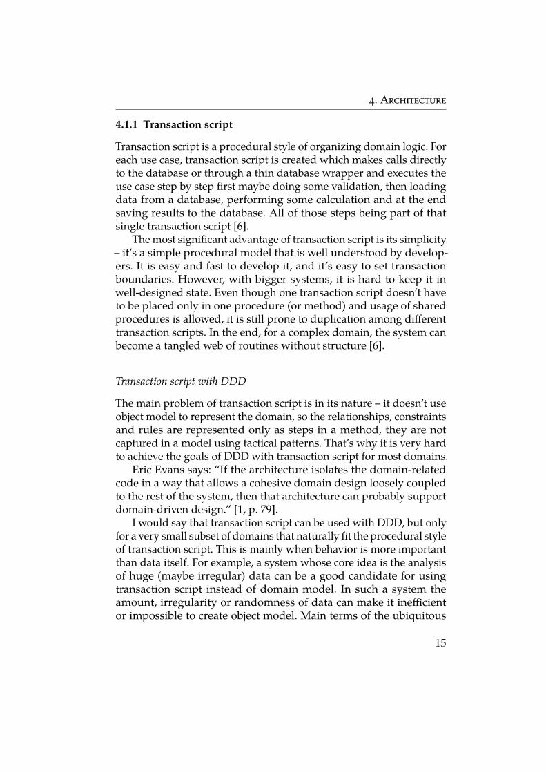
4.1.1 Transaction script
Transaction script is a procedural style of organizing domain logic. Foreach use case, transaction script is created which makes calls directlyto the database or through a thin database wrapper and executes theuse case step by step first maybe doing some validation, then loadingdata from a database, performing some calculation and at the endsaving results to the database. All of those steps being part of thatsingle transaction script [6].
The most significant advantage of transaction script is its simplicity– it’s a simple procedural model that is well understood by develop-ers. It is easy and fast to develop it, and it’s easy to set transactionboundaries. However, with bigger systems, it is hard to keep it inwell-designed state. Even though one transaction script doesn’t haveto be placed only in one procedure (or method) and usage of sharedprocedures is allowed, it is still prone to duplication among differenttransaction scripts. In the end, for a complex domain, the system canbecome a tangled web of routines without structure [6].
Transaction script with DDD
The main problem of transaction script is in its nature – it doesn’t useobject model to represent the domain, so the relationships, constraintsand rules are represented only as steps in a method, they are notcaptured in a model using tactical patterns. That’s why it is very hardto achieve the goals of DDD with transaction script for most domains.
Eric Evans says: “If the architecture isolates the domain-relatedcode in a way that allows a cohesive domain design loosely coupledto the rest of the system, then that architecture can probably supportdomain-driven design.” [1, p. 79].
I would say that transaction script can be used with DDD, but onlyfor a very small subset of domains that naturally fit the procedural styleof transaction script. This is mainly when behavior is more importantthan data itself. For example, a system whose core idea is the analysisof huge (maybe irregular) data can be a good candidate for usingtransaction script instead of domain model. In such a system theamount, irregularity or randomness of data can make it inefficientor impossible to create object model. Main terms of the ubiquitous
15
4. Architecture
language are the actions or calculations that are performed with dataand they can be nicely captured in names of procedures (or methods).These are quite rare situations and while transaction script can beuseful pattern, when used for core domain, usually it suggests thatsystem is not complex enough for DDD to be used. However, it can bestill useful for a generic domain where building a full domain modelcan be a waste of resources that could be rather used for a core domain.
4.1.2 Table module
Table module is another pattern used in domain logic. Its definition liessomewhere between domain model and transaction script. The maindifference between domain model and table module is in the meaningof instances. In domain model one instance of a class usually representsone instance of an entity in real life. For example, the instance of aclass User represents one user in real life. On the other hand, in Tablemodule, there is only one instance which is used for managing allinstances in real life [6]. Clients of this instance need to provide data(e.g., as a list of table rows) on which the instance will work.
This pattern provides more structure than transaction script, butit still misses the expressiveness of domain model. The most signifi-cant advantage of table module is how well it fits with many simpletools that are used for database access, such as ADO.NET or JDBC inJava, so it doesn’t require Object-relational mapping (ORM) tools andcomplicated mapping [6].
Table module with DDD
Even though there exists some kind of organization of methods intoobjects, the full object model is still missing, data are passed aroundin a raw form (for example as they were returned by database wrap-per). Therefore tactical patterns still cannot be used, but it is easier toincorporate ubiquitous language into the code.
Similarly to transaction script, table module should not be usedfor a core domain. If a core domain is very simple and table module isa fitting option, in most cases it means that the domain is not complexenough for DDD. However, table module can still be a good optionfor generic and supporting domains.
16
4. Architecture
4.1.3 Anemic domain model
Anemic domain model is a situation when there is an object modelcreated, which should serve as a domain model, but objects that rep-resent entities or value objects have no behavior, they are designed tobe only data holders and usually contain only getters and setters [7].It is considered to be an anti-pattern because it contradicts the ideasof object-oriented programming, which combines data and behaviortogether. The other problem is that it is costly to create such a model –objects and relationships still need to be crafted, it is necessary to useORM tools, however, it loses the benefits of rich domain model.
Anemic domain model with DDD
While the objects capture the structural view of the domain well, thebehavior with business rules, constraints and actions is placed in adifferent place, usually in some service class. Because of this situation,even though the structural view is close to reality, the behavioral viewis very different from how domain experts think about the domain.
Anemic domain model, therefore, resembles transaction script,however with all the costs of creating object model. Therefore it shouldnot be used. In very specific or generic domains, transaction script ortable module can be considered instead.
4.2 Architecture of bounded contexts
The system that is divided into multiple bounded contexts provides agood opportunity to choose an architecture for one bounded context,independently on other bounded contexts. To be able to have architec-tures of all bounded context independent, also the right architectureon the top level needs to be picked. This is discussed in more detailin section 4.3. This section describes architecture patterns that can beused to decompose a single bounded context.
4.2.1 Big ball of mud
Big ball of mud (BBoM) is an anti-pattern which describes unstruc-tured, randomly interconnected code. BBoM is usually a result of
17
4. Architecture
non-existing architecture, rapid development without thinking aboutdesign, ad hoc modifications, or just lack of knowledge about goodsoftware development practices and principles [8].
Because the code doesn’t have any clear structure, it is very diffi-cult to deal with it, and it becomes very hard to understand, maintainand extend. It is ugly, bug-prone code which all developers hate todeal with. This is especially a big problem if the BBoM is used in thecore domain of a business. Even if the system can currently serve alldemands of business, in the future it will be difficult or even impos-sible to adapt to changes or additions in business requirements andprogressively deliver business value.
Big Ball of Mud with DDD
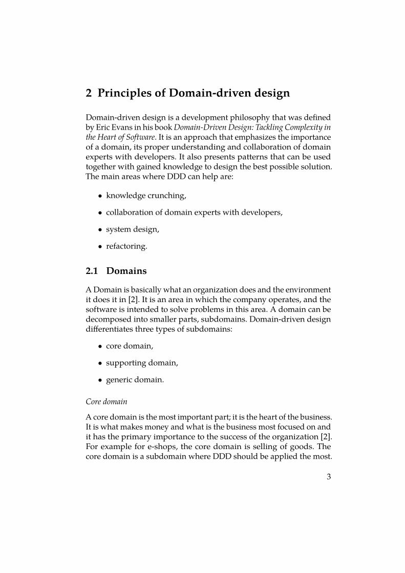
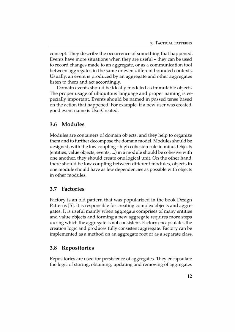
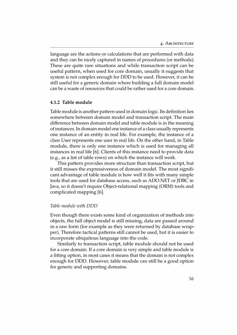
Even though BBoM is generally considered an anti-pattern and shouldnot be used for core domain, there are situations where it can beacceptable to use it. It can be used for low complexity or not veryimportant code, especially in a generic domain. It will decrease thetime to market and save resources that can be rather used for craftingbetter a model in the core domain. When using BBoM, it is importantthat it resides in its own bounded context. Other bounded contextsthat need to communicate with it should use anti-corruption layerwhich will serve as an adapter between "bad" and "good" code. "Good"code, therefore, doesn’t need to be aware of all the complexities ofBBoM and it will not become dependent on it.
Generic Domain
BBoM Context"Good" context
Core domain
Anticorruption layer
Figure 4.1: Big ball of mud with Domain-driven design
18
4. Architecture
4.2.2 Layered Architecture
Layered architecture is one of the most commonly used architecturalpatterns [9]. When using it, the software is logically or physically di-vided into layers, where each layer is at a particular level of abstraction[10]. Each layer encapsulates it’s own logic and exposes a public inter-face to the layer above. Each layer can use only the layer that is onelevel lower (sometimes it can use any layer that is below), dependencyon layers above is not allowed. Typically used layers are presentationlayer (used for displaying content to the user), domain layer (containsdomain logic) and data source layer (used for accessing data in thestore) [6].
Structuring software into layers makes it easier to understand –it is possible to have a look only on one layer without the noise ofother layers. For example, it is possible to understand how particularbusiness operation is implemented without having to know how it isdisplayed to the user and how the data are stored. It is also possible tosubstitute the whole layer with different implementation if it followsthe same contract. For example, we can replace the relational databaseimplementation of the data source layer with NoSQL implementation.
The problem with layered architecture is that it doesn’t abide bythe dependency inversion principle 2. The higher layers usually havea higher level of abstraction, but they depend on lower level layers.It is especially true for the domain layer which depends on the datasource layer which is a low level, infrastructural code.
Layered architecture with DDD
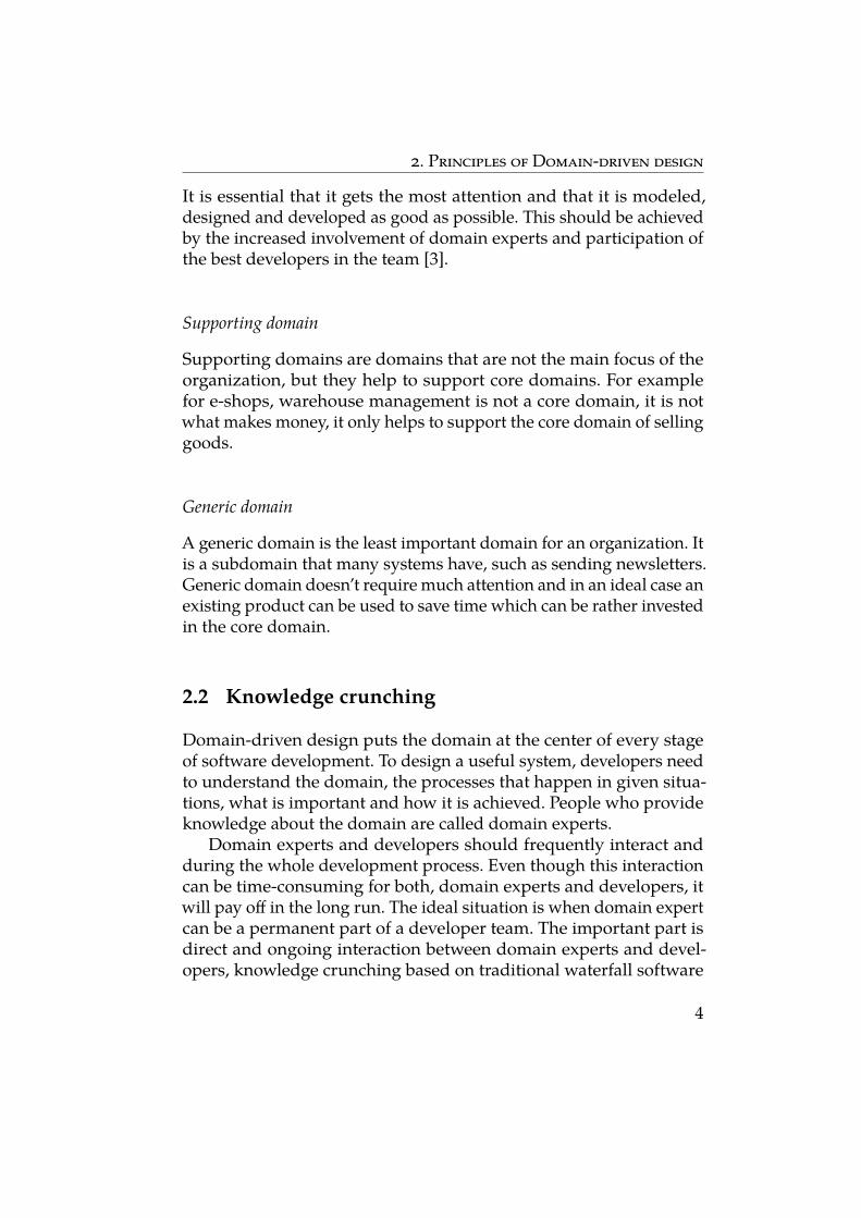
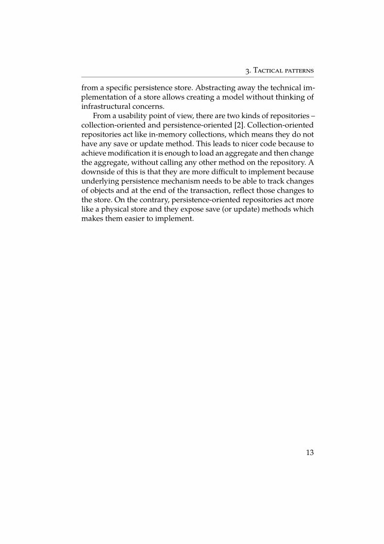
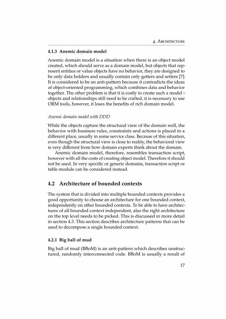
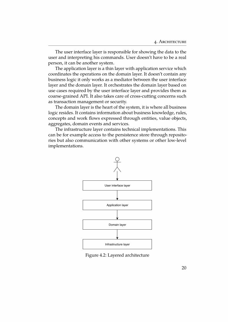
Eric Evans chose in his book layered architecture as the main architec-tural pattern on which he focused the most. He proposed four layersfor DDD (see figure 4.2): user interface layer, application layer, domainlayer and infrastructure layer.
2. Dependency inversion principle is a rule that states that “High-level modulesshould not depend on low-level modules. Both should depend on abstraction”and “Abstraction should not depend upon details. Details should depend uponabstractions” [11].
19
4. Architecture
The user interface layer is responsible for showing the data to theuser and interpreting his commands. User doesn’t have to be a realperson, it can be another system.
The application layer is a thin layer with application service whichcoordinates the operations on the domain layer. It doesn’t contain anybusiness logic it only works as a mediator between the user interfacelayer and the domain layer. It orchestrates the domain layer based onuse cases required by the user interface layer and provides them ascoarse-grained API. It also takes care of cross-cutting concerns suchas transaction management or security.
The domain layer is the heart of the system, it is where all businesslogic resides. It contains information about business knowledge, rules,concepts and work flows expressed through entities, value objects,aggregates, domain events and services.
The infrastructure layer contains technical implementations. Thiscan be for example access to the persistence store through reposito-ries but also communication with other systems or other low-levelimplementations.
User interface layer
Application layer
Domain layer
Infrastructure layer
Figure 4.2: Layered architecture
20
4. Architecture
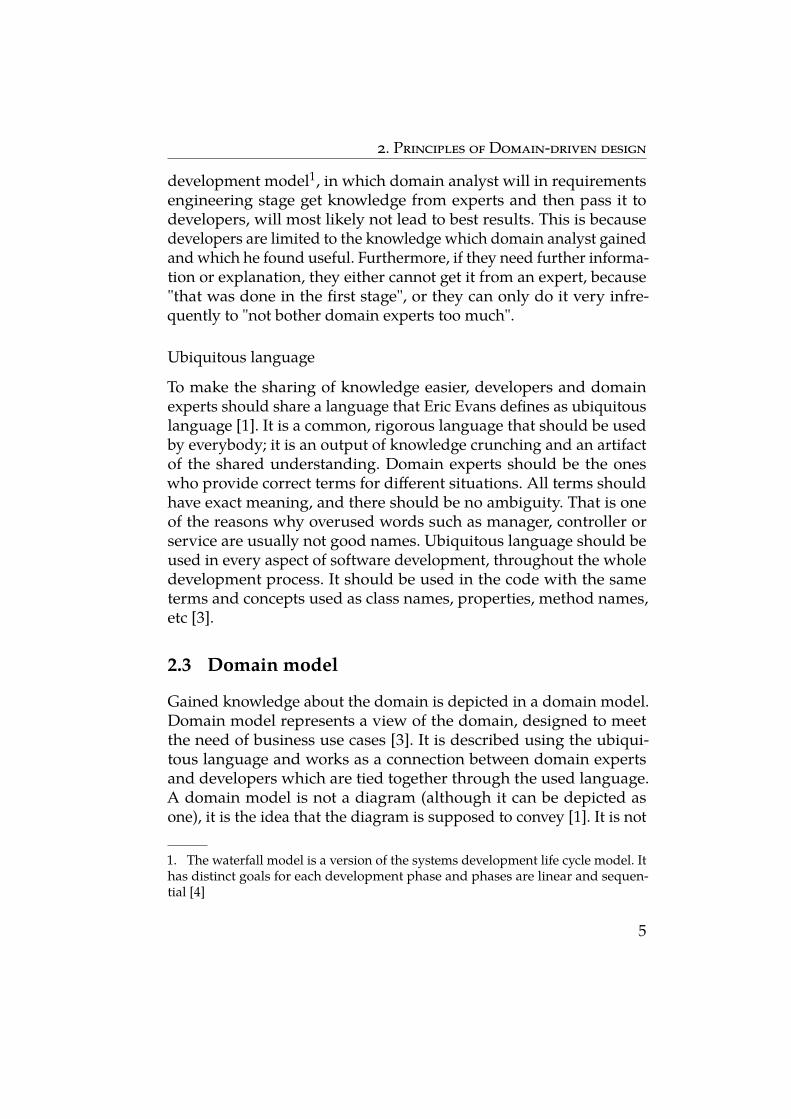
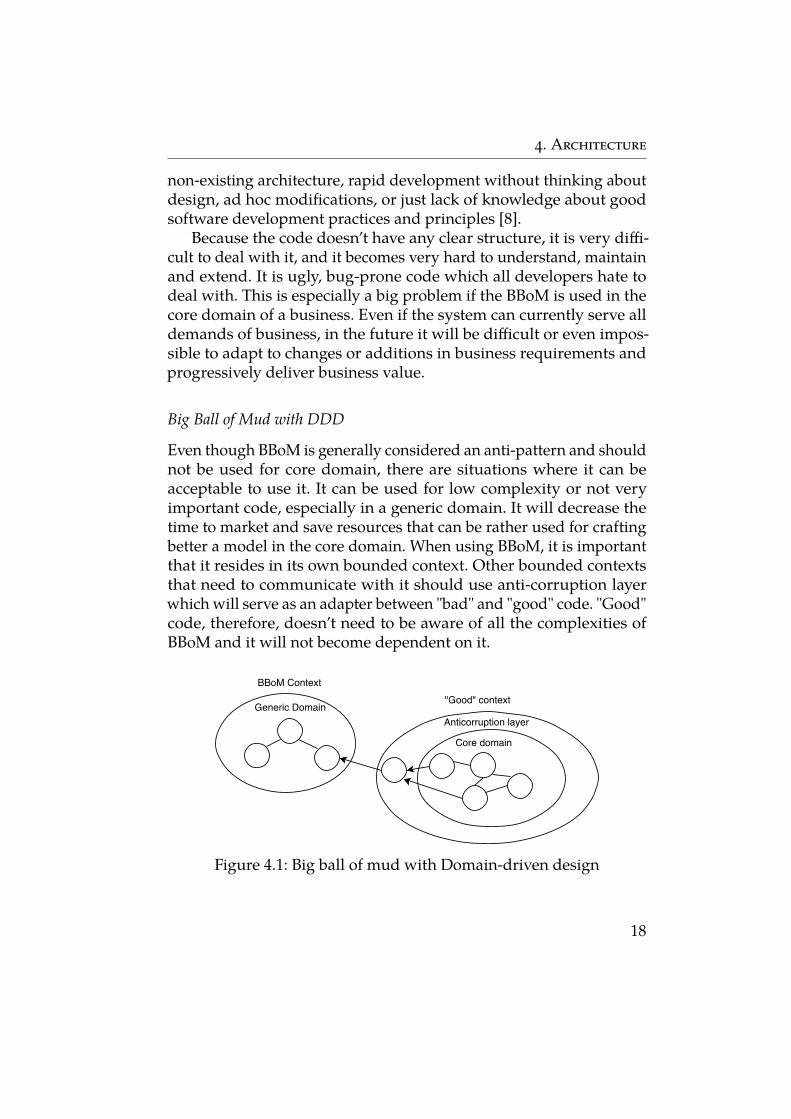
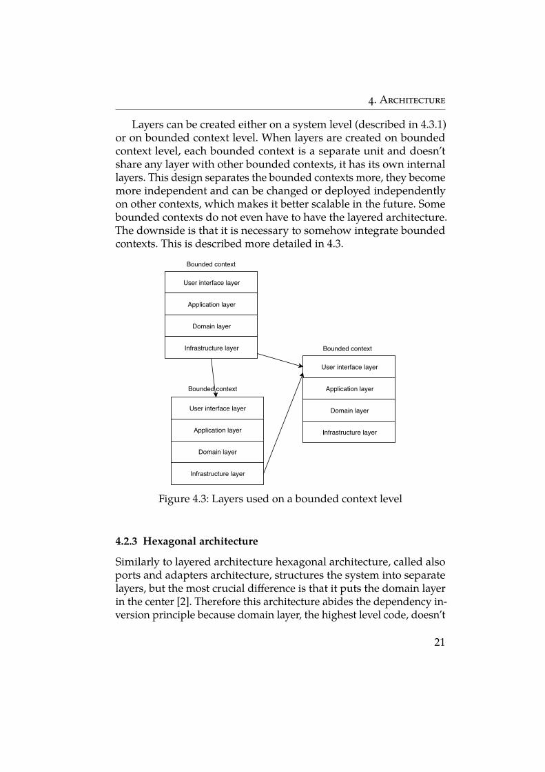
Layers can be created either on a system level (described in 4.3.1)or on bounded context level. When layers are created on boundedcontext level, each bounded context is a separate unit and doesn’tshare any layer with other bounded contexts, it has its own internallayers. This design separates the bounded contexts more, they becomemore independent and can be changed or deployed independentlyon other contexts, which makes it better scalable in the future. Somebounded contexts do not even have to have the layered architecture.The downside is that it is necessary to somehow integrate boundedcontexts. This is described more detailed in 4.3.
User interface layer
Application layer
Domain layer
Infrastructure layer
User interface layer
Application layer
Domain layer
Infrastructure layer
User interface layer
Application layer
Domain layer
Infrastructure layer
Bounded context
Bounded context
Bounded context
Figure 4.3: Layers used on a bounded context level
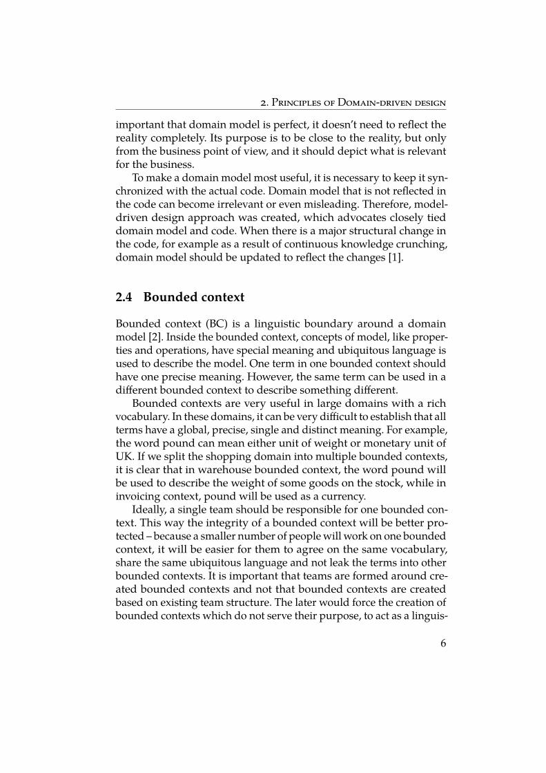
4.2.3 Hexagonal architecture
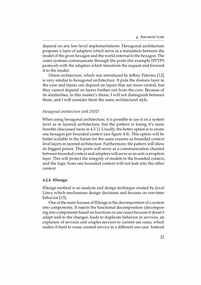
Similarly to layered architecture hexagonal architecture, called alsoports and adapters architecture, structures the system into separatelayers, but the most crucial difference is that it puts the domain layerin the center [2]. Therefore this architecture abides the dependency in-version principle because domain layer, the highest level code, doesn’t
21
4. Architecture
depend on any low-level implementations. Hexagonal architectureproposes a layer of adapters which serve as a translation between themodel of the given hexagon and the world external to the hexagon. Theouter systems communicate through the ports (for example HTTPSprotocol) with the adapters which transform the request and forwardit to the model.
Onion architecture, which was introduced by Jeffrey Palermo [12],is very similar to hexagonal architecture. It puts the domain layer inthe core and layers can depend on layers that are more central, butthey cannot depend on layers further out from the core. Because ofits similarities, in this master’s thesis, I will not distinguish betweenthem, and I will consider them the same architectural style.
Hexagonal architecture with DDD
When using hexagonal architecture, it is possible to use it on a systemlevel as in layered architecture, but the pattern is losing it’s mainbenefits (discussed more in 4.3.1). Usually, the better option is to createone hexagon per bounded context (see figure 4.4). This option will bebetter scalable in the future for the same reasons as bounded contextlevel layers in layered architecture. Furthermore, the pattern will showits biggest power. The ports will serve as a communication channelbetween bounded context and adapters will serve as an anti-corruptionlayer. This will protect the integrity of models in the bounded context,and the logic from one bounded context will not leak into the othercontext.
4.2.4 IDesign
IDesign method is an analysis and design technique created by JuvalLöwy which mechanizes design decisions and focuses on run-timebehavior [13].
One of the main focuses of IDesign is the decomposition of a systeminto components. It rejects the functional decomposition (decompos-ing into components based on functions or use cases) because it doesn’tadapt well to the changes, leads to duplicate behavior in services, anexplosion of services and couples services to current use cases, whichmakes it hard to reuse created service in a different use case. Instead,
22
4. Architecture
Domain model
Application services
Infra
struc
tureUser interface
Adapters layer
Figure 4.4: Hexagonal architecture of one bounded context
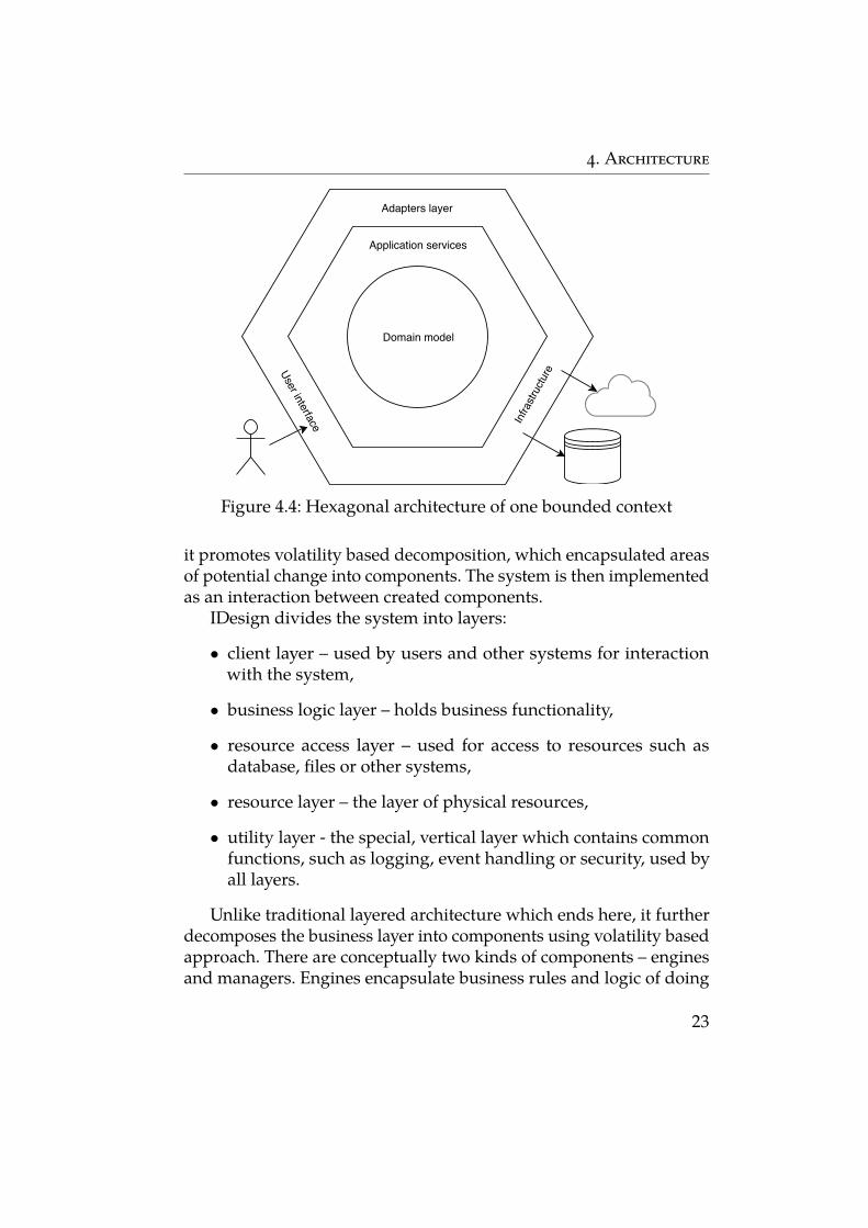
it promotes volatility based decomposition, which encapsulated areasof potential change into components. The system is then implementedas an interaction between created components.
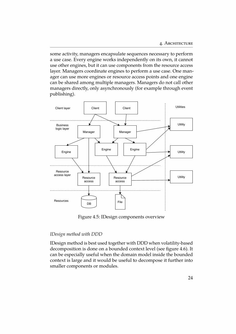
IDesign divides the system into layers:
∙ client layer – used by users and other systems for interactionwith the system,
∙ business logic layer – holds business functionality,
∙ resource access layer – used for access to resources such asdatabase, files or other systems,
∙ resource layer – the layer of physical resources,
∙ utility layer - the special, vertical layer which contains commonfunctions, such as logging, event handling or security, used byall layers.
Unlike traditional layered architecture which ends here, it furtherdecomposes the business layer into components using volatility basedapproach. There are conceptually two kinds of components – enginesand managers. Engines encapsulate business rules and logic of doing
23
4. Architecture
some activity, managers encapsulate sequences necessary to performa use case. Every engine works independently on its own, it cannotuse other engines, but it can use components from the resource accesslayer. Managers coordinate engines to perform a use case. One man-ager can use more engines or resource access points and one enginecan be shared among multiple managers. Managers do not call othermanagers directly, only asynchronously (for example through eventpublishing).
Client Client
Manager Manager
Engine Engine
Engine
Utility
Resourceaccess
Resourceaccess
FileDB
Utility
Utility
Client layer
Businesslogic layer
Resourceaccess layer
Resources
Utilities
Figure 4.5: IDesign components overview
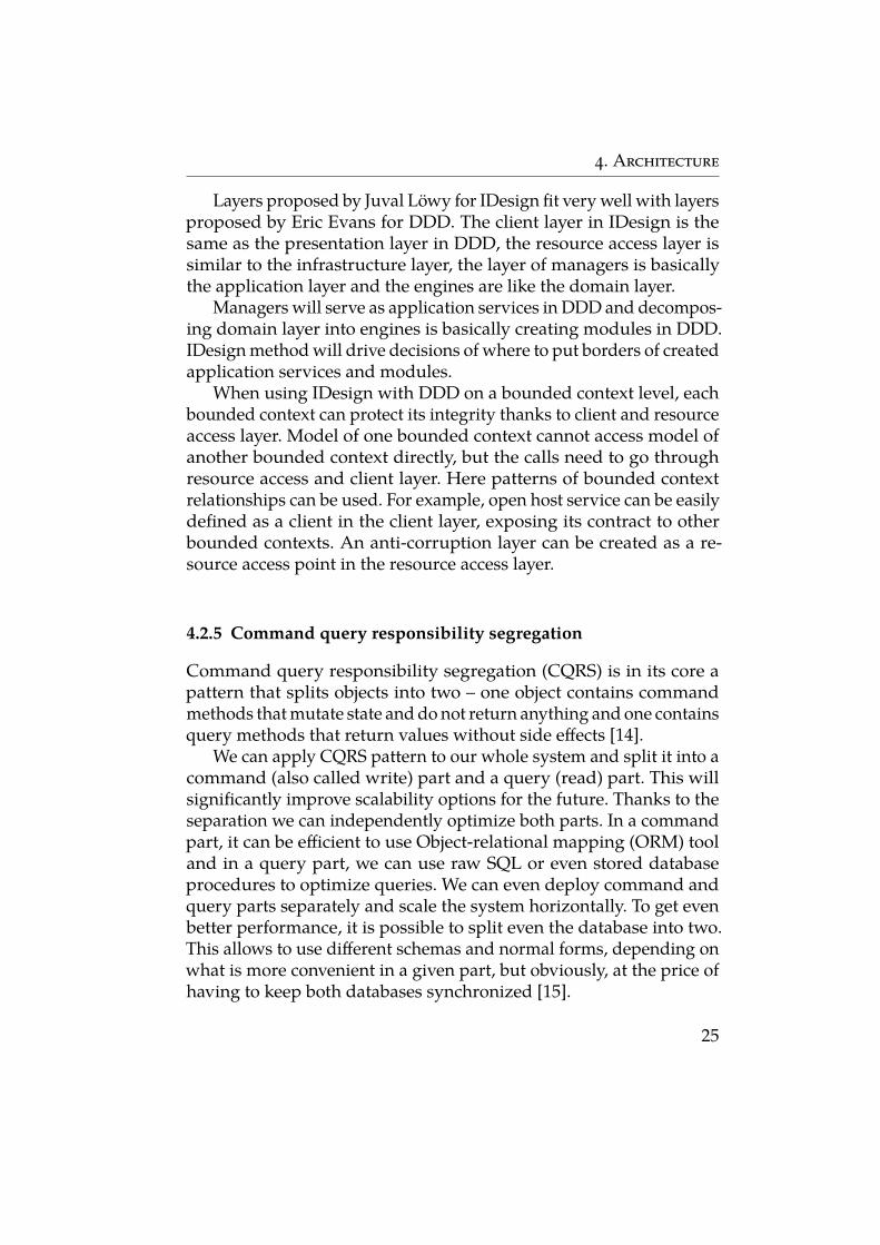
IDesign method with DDD
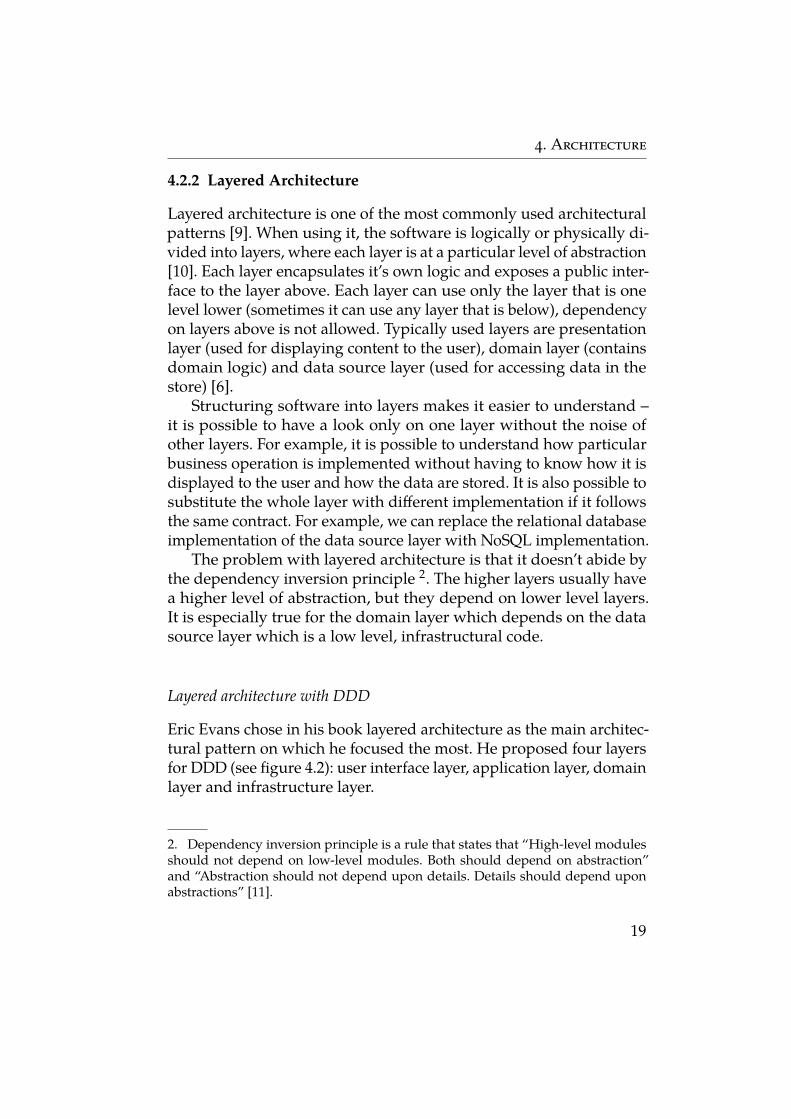
IDesign method is best used together with DDD when volatility-baseddecomposition is done on a bounded context level (see figure 4.6). Itcan be especially useful when the domain model inside the boundedcontext is large and it would be useful to decompose it further intosmaller components or modules.
24
4. Architecture
Layers proposed by Juval Löwy for IDesign fit very well with layersproposed by Eric Evans for DDD. The client layer in IDesign is thesame as the presentation layer in DDD, the resource access layer issimilar to the infrastructure layer, the layer of managers is basicallythe application layer and the engines are like the domain layer.
Managers will serve as application services in DDD and decompos-ing domain layer into engines is basically creating modules in DDD.IDesign method will drive decisions of where to put borders of createdapplication services and modules.
When using IDesign with DDD on a bounded context level, eachbounded context can protect its integrity thanks to client and resourceaccess layer. Model of one bounded context cannot access model ofanother bounded context directly, but the calls need to go throughresource access and client layer. Here patterns of bounded contextrelationships can be used. For example, open host service can be easilydefined as a client in the client layer, exposing its contract to otherbounded contexts. An anti-corruption layer can be created as a re-source access point in the resource access layer.
4.2.5 Command query responsibility segregation
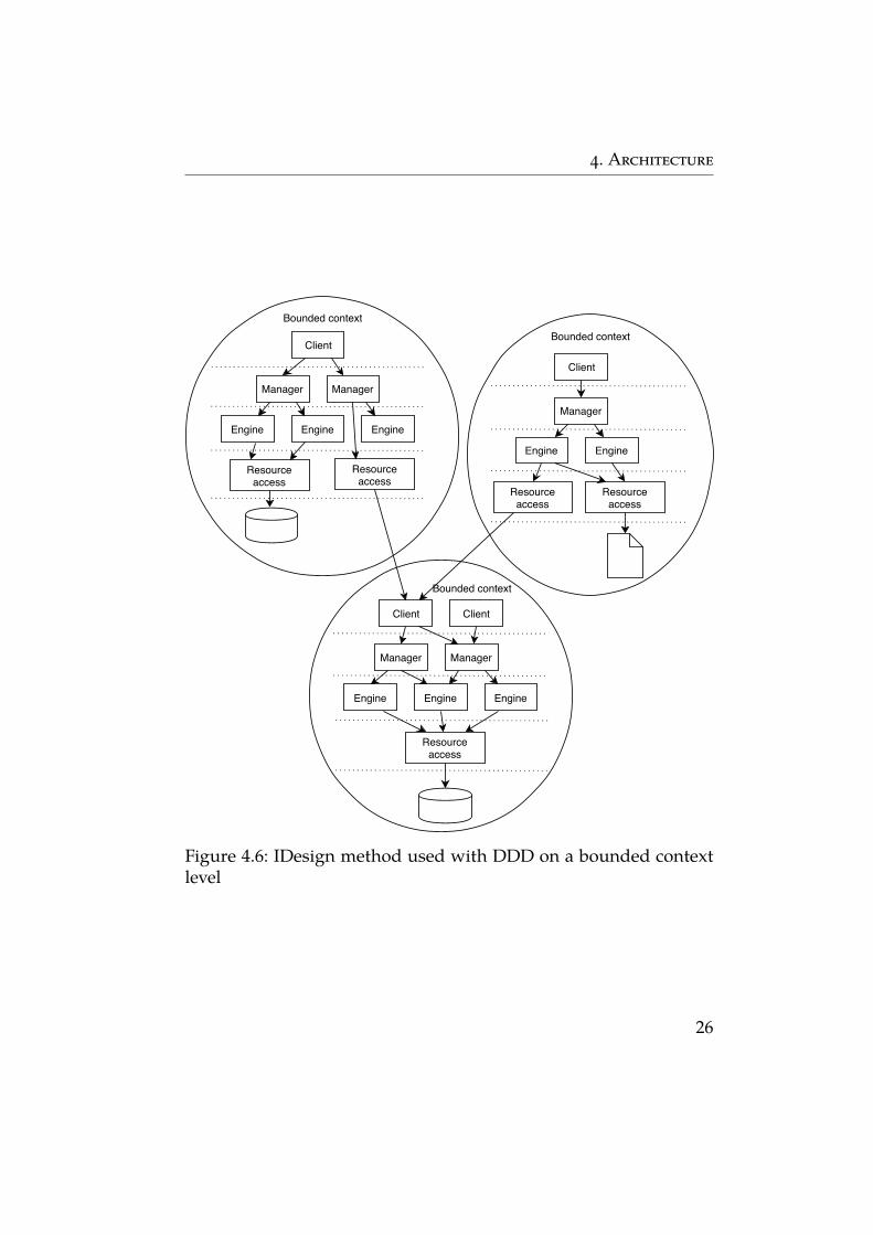
Command query responsibility segregation (CQRS) is in its core apattern that splits objects into two – one object contains commandmethods that mutate state and do not return anything and one containsquery methods that return values without side effects [14].
We can apply CQRS pattern to our whole system and split it into acommand (also called write) part and a query (read) part. This willsignificantly improve scalability options for the future. Thanks to theseparation we can independently optimize both parts. In a commandpart, it can be efficient to use Object-relational mapping (ORM) tooland in a query part, we can use raw SQL or even stored databaseprocedures to optimize queries. We can even deploy command andquery parts separately and scale the system horizontally. To get evenbetter performance, it is possible to split even the database into two.This allows to use different schemas and normal forms, depending onwhat is more convenient in a given part, but obviously, at the price ofhaving to keep both databases synchronized [15].
25
4. Architecture
Client
Resourceaccess
Manager Manager
Engine Engine Engine
Resourceaccess
Client
Resourceaccess
Manager
Engine Engine
Resourceaccess
Client Client
Resourceaccess
Manager Manager
Engine Engine Engine
Bounded contextBounded context
Bounded context
Figure 4.6: IDesign method used with DDD on a bounded contextlevel
26
4. Architecture
Even though CQRS has its advantages, it brings complexity to thesystem. Therefore it should be carefully considered if CQRS is worththe effort. Lots of domains do not have their querying and modificationlogic very independent and there is enough overlap for both parts tostay merged together. Also, many systems will probably do not needscalability level provided by CQRS [16].
Command part Query part
Command
OK/NOK
SaveSimple get Data
Query Data
Figure 4.7: CQRS applied to the whole system with two databases
Because CQRS splits the system into two, usually large parts, thearchitecture of each part should be considered as well. For example,the command part can use hexagonal architecture, for the read part,simple layered architecture is usually enough.
27
4. Architecture
CQRS with DDD
CQRS can bring multiple advantages to the systems that use DDD.The biggest advantage is that it helps us to look at the domain model(which resides in the command part) from a behavioral point of view.Domain objects can focus more on the behavior and business rulesand less on how to hold or return data because they will not be usedfor that. This will make the model closer to the ubiquitous languageand it will reflect how domain experts use the software.
Because we have a dedicated query part, repositories can be sim-plified, they will not need to take care of querying by different criteria,but they can focus more on writing to the store. Also, the problemswith queries that cut across multiple aggregates will be solved.
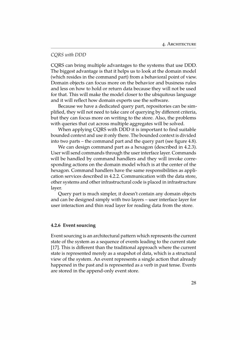
When applying CQRS with DDD it is important to find suitablebounded context and use it only there. The bounded context is dividedinto two parts – the command part and the query part (see figure 4.8).
We can design command part as a hexagon (described in 4.2.3).User will send commands through the user interface layer. Commandswill be handled by command handlers and they will invoke corre-sponding actions on the domain model which is at the center of thehexagon. Command handlers have the same responsibilities as appli-cation services described in 4.2.2. Communication with the data store,other systems and other infrastructural code is placed in infrastructurelayer.
Query part is much simpler, it doesn’t contain any domain objectsand can be designed simply with two layers – user interface layer foruser interaction and thin read layer for reading data from the store.
4.2.6 Event sourcing
Event sourcing is an architectural pattern which represents the currentstate of the system as a sequence of events leading to the current state[17]. This is different than the traditional approach where the currentstate is represented merely as a snapshot of data, which is a structuralview of the system. An event represents a single action that alreadyhappened in the past and is represented as a verb in past tense. Eventsare stored in the append-only event store.
28
4. Architecture
Domainmodel
Command handlers
User
inte
rface
Infrastructure
User interface
Read layer
Command part
Query part
Figure 4.8: CQRS using DDD
29
4. Architecture
The biggest advantage of event sourcing is that it brings substantialbusiness value. Thanks to the event store, by replaying events, we canget to any state in the history of the system. The system is also not tiedto one specific structural view, but different views can be created, inthe future views that currently are not useful can be created, eventscontain all data necessary for it. Another advantage is easier handlingof mistakes. When we notice that incorrect action happened in thepast, we can easily rollback state to that point and then replay onlycorrect events. From a technical point of view, event sourcing alsobrings better scalability. Thanks to the append store nature, no locksare necessary and partitioning is easier to achieve.
Event sourcing brings also challenges when being implemented.One of them is how data are going to be read when queried by theuser. They cannot be queried directly from the event store because itstores only raw events and replaying events every time would take toomuch time. To solve this, CQRS can be used which creates the secondmodel which basically represents the structural view of the systemat the current point in time and is used for reading. Read model isupdated every time a new event is added to the event store by anevent handler designated for this purpose. To improve the scalability,eventual consistency is usually used when synchronizing event storeand read model.
Another performance bottleneck can happen if it is necessary toreplay too many events to get to the current state (and then to per-form some action). This problem is mitigated by creating snapshots ofobjects in a given state and saving the serialized state. After that, toget to the current state, it is enough to replay events from the latestsnapshot.
To be able to extend the system with new requirements, it is neces-sary to be able to adapt to new versions of events. This is problematicbecause the event store already contains old serialized events so itis not possible to just rename a class attribute. A new class that rep-resents new version is usually created. Because of different versionof an event, event handlers either need to handle all events directly,or mechanism for transforming old events to new events needs to becreated.
Event sourcing can bring substantial business value, but it shouldbe carefully considered whether it is worth the effort. The domain
30
4. Architecture
should be complex enough and the events happening in the domainshould be distinct.
Event sourcing with DDD
Understanding the state as a chain of events rather than a snapshot,makes many systems look more close to reality. In many situations,domain experts think about a business as a sequence of events [15].For example in the banking domain, an account is not represented asa simple number representing account balance but as a collection ofdeposits and withdrawals leading to the present.
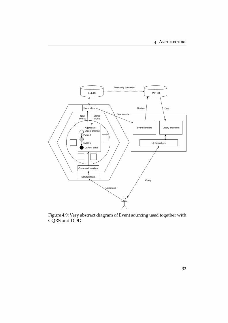
With DDD, Event sourcing is used on an aggregate level (see fig-ure 4.9), state of an aggregate is represented by events related to it[2]. "Encapsulating" event sourcing in each aggregate fits very wellwith transaction boundaries. Because aggregates represent consis-tency boundary, making events (related to event sourcing) internalto an aggregate, makes sure the boundary is not crossed. Also, a niceside effect of Event sourcing is that it makes API of an aggregate morebehavior-oriented, which again is closer to the perception of domainby domain experts [3]. The simple nature of a persistence store makesaggregates very persistence independent, there is no need for difficultORM mechanisms.
4.2.7 Pipes and filters
Pipes and filters pattern brings structure to systems that deal with astream of data in multiple processing steps. It decomposes the systeminto smaller components called filter, where each filter is dedicated forone processing step. Filters are organized into a pipeline, where filtersare connected through a pipe [10]. It comprises four main components:
∙ Filter – it is used for processing data and transforming input tooutput. The filter needs to adhere to some contract that specifiesthe format of input and output data.
∙ Data source – the source of data with the same structure whichare provided to the system. The data source can either activelypush or wait until filters request data.
31
4. Architecture
Blob DB 1NF DB
Event 1
Event 2
Object created
Current state
Storedevents
Newevents
Aggregate
Eventually consistent
New events
Update DataEvent store
Command handlers
UI Controllers
Event handlers Query executors
UI Controllers
Query
Command
Figure 4.9: Very abstract diagram of Event sourcing used together withCQRS and DDD
32
4. Architecture
∙ Data sink – it is the end of the pipeline, it can either activelyrequest data from the last filter or passively consume data pro-vided by the filter.
∙ Pipe – represents a connection between filters, data source ordata sink.
Pipes and filters bring flexibility to the system because a filter canbe replaced without other filters in the pipeline being affected. Also iffilters are well-designed, they can be reused in different pipelines.
The biggest problem with pipes and filters is error handling. Whenan unexpected situation occurs in the filter in the middle of a pipelineit is often not clear how to continue. Mainly because the filter couldalready process some of the input data and produced some resultwhich could already reach the data sink.
Pipes and filters with DDD
Pipes and filters is a very specific pattern, and not many DDD sys-tems or subsystems will benefit from it. It cannot be used for manytypical domains that usually do not use stream-like data required bythis pattern. Also rather broad data model with event-driven behav-ior of many domains would make usage of filters inefficient or evenimpossible in both development and also execution time.
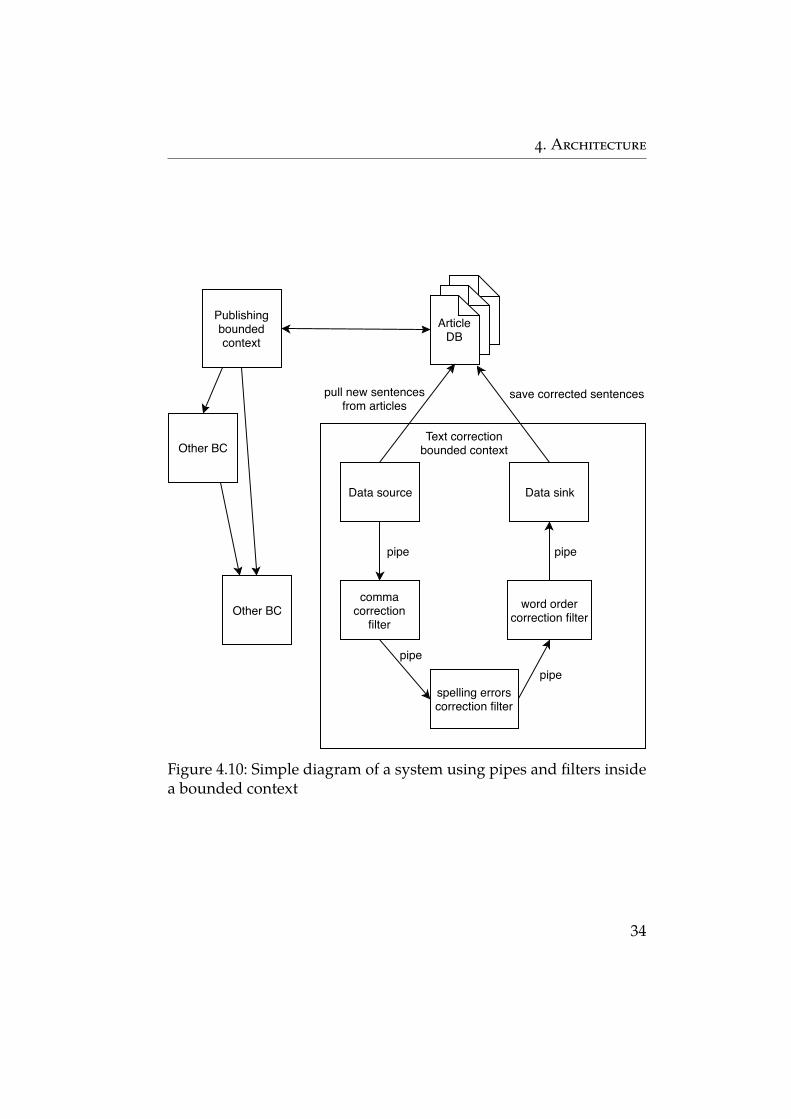
Even though not very common, there can be a subdomain wherepipes and filters can fit. For example, a newspaper publisher companycan have text correction for articles as one of its supporting domain.They created new algorithms for correcting text and pipes and filterscan be a good pattern for designing this subdomain. An article can beviewed as a stream of sentences which are provided to the pipelinewith different filters – filter for correcting the use of commas, anotherfor correcting spelling errors, word order and so on.
Figure 4.10 shows a simple diagram of such a system. The datasource is actively pulling new articles from database. Other compo-nents are passing and they are waiting for data.
33
4. Architecture
Publishingboundedcontext
ArticleDB
Data source
commacorrection
filter
spelling errorscorrection filter
word ordercorrection filter
Data sink
pipe
pipe pipe
pipe
save corrected sentencespull new sentencesfrom articles
Text correctionbounded context
Other BC
Other BC
Figure 4.10: Simple diagram of a system using pipes and filters insidea bounded context
34
4. Architecture
4.3 Top-level architecture
This chapter describes architectural patterns that can be used on thehighest level of the system. It will consider only complex systems withmultiple bounded contexts because for a simple system with only onebounded context these ideas are not necessary. For systems with onlyone bounded context, the patterns mentioned in the previous chaptercan be used.
4.3.1 Monolithic architecture
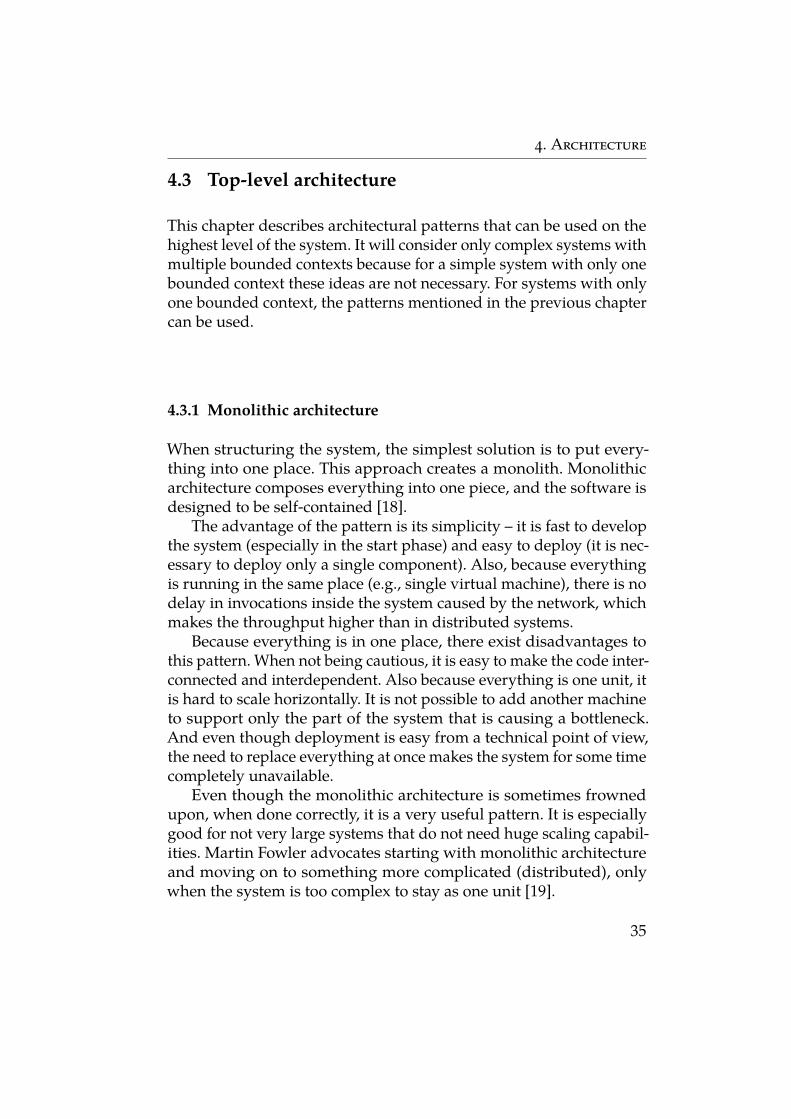
When structuring the system, the simplest solution is to put every-thing into one place. This approach creates a monolith. Monolithicarchitecture composes everything into one piece, and the software isdesigned to be self-contained [18].
The advantage of the pattern is its simplicity – it is fast to developthe system (especially in the start phase) and easy to deploy (it is nec-essary to deploy only a single component). Also, because everythingis running in the same place (e.g., single virtual machine), there is nodelay in invocations inside the system caused by the network, whichmakes the throughput higher than in distributed systems.
Because everything is in one place, there exist disadvantages tothis pattern. When not being cautious, it is easy to make the code inter-connected and interdependent. Also because everything is one unit, itis hard to scale horizontally. It is not possible to add another machineto support only the part of the system that is causing a bottleneck.And even though deployment is easy from a technical point of view,the need to replace everything at once makes the system for some timecompletely unavailable.
Even though the monolithic architecture is sometimes frownedupon, when done correctly, it is a very useful pattern. It is especiallygood for not very large systems that do not need huge scaling capabil-ities. Martin Fowler advocates starting with monolithic architectureand moving on to something more complicated (distributed), onlywhen the system is too complex to stay as one unit [19].
35
4. Architecture
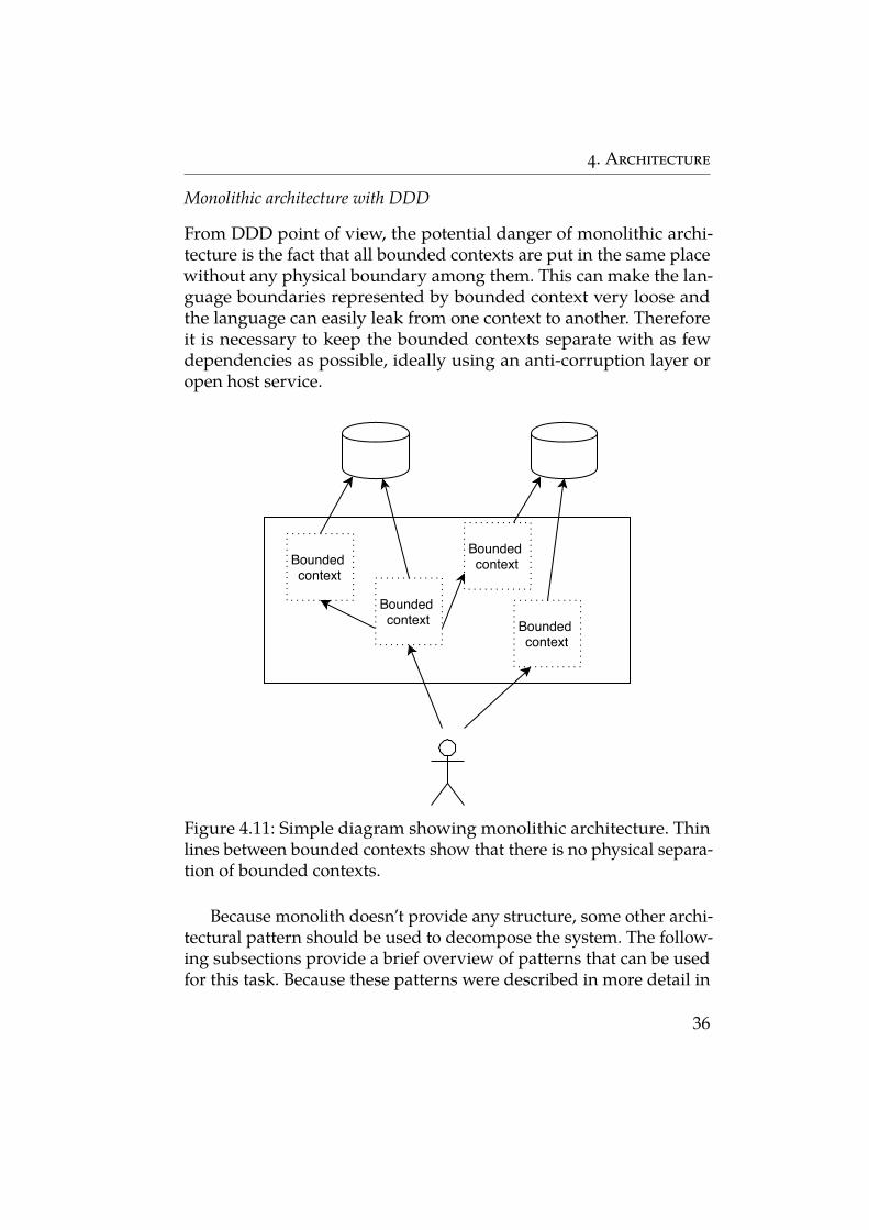
Monolithic architecture with DDD
From DDD point of view, the potential danger of monolithic archi-tecture is the fact that all bounded contexts are put in the same placewithout any physical boundary among them. This can make the lan-guage boundaries represented by bounded context very loose andthe language can easily leak from one context to another. Thereforeit is necessary to keep the bounded contexts separate with as fewdependencies as possible, ideally using an anti-corruption layer oropen host service.
Bounded context
Bounded context
Bounded context
Bounded context
Figure 4.11: Simple diagram showing monolithic architecture. Thinlines between bounded contexts show that there is no physical separa-tion of bounded contexts.
Because monolith doesn’t provide any structure, some other archi-tectural pattern should be used to decompose the system. The follow-ing subsections provide a brief overview of patterns that can be usedfor this task. Because these patterns were described in more detail in
36
4. Architecture
4.2, here will be only briefly described advantages and disadvantagesof those patterns used for the whole monolith.
Big ball of mud
Big ball of mud is an unstructured, randomly interconnected code.Therefore it would not be possible to have clear borders betweenbounded contexts and thus keep the linguistic boundary of eachbounded context. Additionally, the maintenance and extensibilityburden which comes with the pattern makes it a very bad option fornot only DDD systems.
Layers
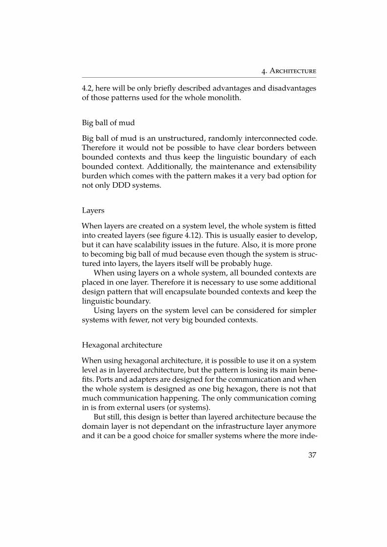
When layers are created on a system level, the whole system is fittedinto created layers (see figure 4.12). This is usually easier to develop,but it can have scalability issues in the future. Also, it is more proneto becoming big ball of mud because even though the system is struc-tured into layers, the layers itself will be probably huge.
When using layers on a whole system, all bounded contexts areplaced in one layer. Therefore it is necessary to use some additionaldesign pattern that will encapsulate bounded contexts and keep thelinguistic boundary.
Using layers on the system level can be considered for simplersystems with fewer, not very big bounded contexts.
Hexagonal architecture
When using hexagonal architecture, it is possible to use it on a systemlevel as in layered architecture, but the pattern is losing its main bene-fits. Ports and adapters are designed for the communication and whenthe whole system is designed as one big hexagon, there is not thatmuch communication happening. The only communication comingin is from external users (or systems).
But still, this design is better than layered architecture because thedomain layer is not dependant on the infrastructure layer anymoreand it can be a good choice for smaller systems where the more inde-
37
4. Architecture
User interface layer
Application layer
Infrastructure layer
Domain layer
BC BC
BC
Figure 4.12: Layers used on a system level
38
4. Architecture
pendent separation of bounded context is not necessary and it doesn’tmatter that they all reside in one hexagon.
IDesign
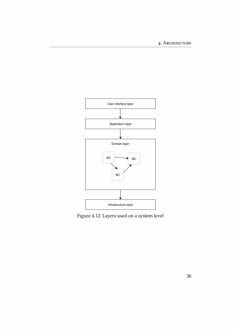
Using IDesign for decomposition on a system level doesn’t fit wellwith Domain-driven design for multiple reasons.
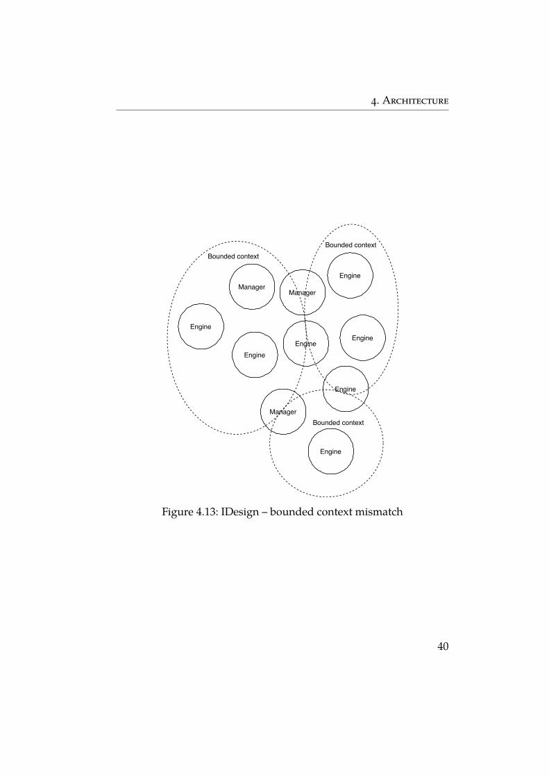
In DDD, bounded contexts are created based on the domain andthe language used, they serve as a linguistic boundary around a do-main model. On the other hand, IDesign decomposition is basedon volatility, components encapsulate areas of possible change. IfIDesign would be used for decomposition, components wouldn’tmatch bounded contexts (see figure 4.13). Two bounded contexts couldeasily extend to one component. This can happen for example whenwe create a calculation component, but we do not consider domainaspect. In this component, the calculation of product discount for cus-tomer and calculation of stock refill dates will fall, but both of thosefunctions will be probably part of different bounded context. Whileit would be possible to draw a logical boundary between boundedcontexts in one component, there is no guarantee it will not be crossedin the future.
Another problem of using IDesign decomposition on system levelis the difficulty of enforcing relationship patterns between boundedcontexts (described in 2.5). Even if we manage to create componentswith each component exclusive to exactly one bounded context, if wewould want to create for example open host service for one BC, wewould need to create it on all components of given BC. This would berepetitive work prone to inconsistencies.
CQRS
Dividing the whole system into two parts with CQRS would bringhuge complexity to the system. There are only several domains (orsubdomains) that have independent querying and modification logic.CQRS should be restricted only to those parts and it should not beapplied to the system as a whole [16].
39
4. Architecture
Engine
Manager
EngineEngine
Manager
Engine
Engine
Manager
Engine
Engine
Bounded contextBounded context
Bounded context
Figure 4.13: IDesign – bounded context mismatch
40
4. Architecture
Event sourcing
Event sourcing requires a domain where events are distinct and advan-tages of event sourcing would bring substantial business value. Ap-plying event sourcing to the whole system is not a good idea becauseit would bring unnecessary complexity to the parts of the systems thatare not suitable for it.
Pipes and filters
Pipes and filters is a very specific pattern which is suitable only for asmall subset of domains that work with stream-like data. Using it onthe whole system might be not only extremely inefficient but probablyimpossible.
4.3.2 Service-oriented architecture (SOA)
SOA is used by enterprises to enhance the agility and cost-effectiveness,while reducing the burden of IT on the organization, by positioningservices as the primary means through which the solution logic isrepresented [20]. It is hard to precisely define what SOA means exactlybecause the term became very ambiguous and for different peoplemeans different things [21].
From a technical point of view, SOA splits functions into distinctunits called services. Services are accessible over the network in orderto allow users to combine and reuse them when creating applications.Services and their consumers communicate together by passing datain a well-defined format [22].
Another definition uses more concrete terms describing it as anarchitectural style for building systems based on the interaction ofloosely coupled, coarse-grained and autonomous services, where eachservice exposes behavior through contracts composed of messages atdiscoverable addresses called endpoints [23].
In recent years microservice architecture became very popular.Martin Fowler describes microservice architecture pattern as “an ap-proach to developing a single application as a suite of small services,each running in its own process and communicating with lightweightmechanisms, often an HTTP resource API” [24]. This description isvery close to the description of SOA. Because of the ambiguity and
41
4. Architecture
different understandings, it is hard to define the differences precisely.For this section the differences are negligible, important is the shiftfrom monolith to services and even though from now on only the termSOA is used, all described principles would apply to microservicestoo.
Although there are no precise industry standards for exact compo-sition of SOA, there exist principles and practices for service design[25]:
∙ standardized contract – services expose their functions throughcontracts, to which other services adhere to;
∙ loose coupling – services should have a minimal amount ofdependencies among each other;
∙ abstraction – services hide their inner implementation and theyexpose only their contract;
∙ reusability – it should be possible to reuse the same service indifferent scenarios;
∙ autonomy – services control their environment and are indepen-dent of other services;
∙ statelessness – services do not manage the state, but they deferit to consumers;
∙ discoverability – services are described with metadata so thatthey can be discovered and interpreted correctly;
∙ composability – services can be composed to create more coarse-grained services.
Names of some principles already imply some advantages of SOAsuch as looser coupling or good reusability. Other advantages are forexample scalability (it is possible to independently scale the servicethat is causing performance problems), availability (a service can bedeployed independently, with other services still running) or flexibility(services can be easily changed, replaced and combined).
Even though service-oriented architecture has many advantages,the price is the increased complexity (to adhere to principles of service
42
4. Architecture
design) and the additional overhead of the communication betweenservices.
SOA with DDD
SOA can be used with DDD to decompose the system into serviceswhere each service represents one bounded context. If beforemen-tioned principles of service design are used it has numerous advan-tages from DDD point of view.
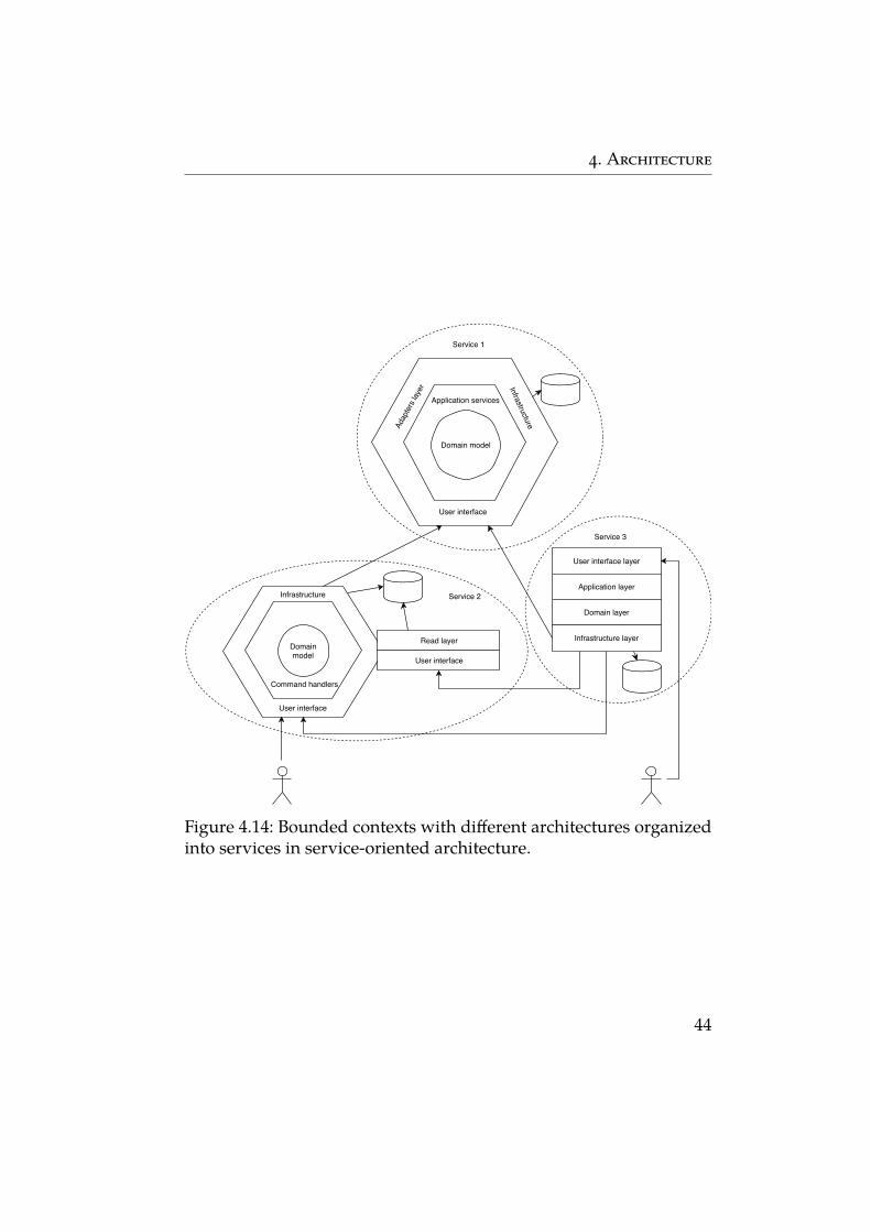
Each bounded context is nicely encapsulated inside a service.Thanks to this we can use different architectures of bounded con-text in different services (see figure 4.14). For one bounded contextwe can choose classical layered architecture, the domain in anotherbounded context can be suitable for event sourcing and the simple,not important bounded context with generic domain, can use evenbig ball of mud. Thanks to a service contract, which is basically anopen host service pattern, the architecture is kept inside the serviceand implementation design doesn’t leak into another service.
Another advantage of encapsulation is the clear boundary whichis created around a bounded context. This way the potential of thebounded context is used to the fullest – it really serves its purpose ofbeing a linguistic boundary. Service contract and abstraction, whichact also as a published language pattern, ensure that the languagedoesn’t leak outside the service into other bounded contexts.
Because SOA brings with itself additional complexity, it is a betterfit for bigger systems with many bounded contexts, resulting in manyservices, to fully use the potential of service orientation.
4.4 Integration of bounded contexts
In previous sections, the architectures that can be used for a boundedcontext where described as well as the architecture on the top level.However, still is missing the link between contexts, how they will beintegrated to fulfill use cases spanning across more contexts. Therecan be a lot said about integration and integration patterns, but inthis section, integration will be described only briefly because it ismore of a technical aspect than a domain aspect. There is no need
43
4. Architecture
Domain model
Application services
Infrastructure
User interface
Adap
ters
laye
r
User interface layer
Application layer
Domain layer
Infrastructure layerDomainmodel
Command handlers
User interface
Infrastructure
User interface
Read layer
Service 2
Service 1
Service 3
Figure 4.14: Bounded contexts with different architectures organizedinto services in service-oriented architecture.
44
4. Architecture
for integration in monolith application, this chapter will, therefore,consider only SOA.
There are four main integration styles [26]:
∙ file transfer,
∙ shared database,
∙ remote procedure invocation,
∙ messaging.
4.4.1 File transfer
Perhaps the simplest option of how to integrate services is by usingfiles which are shared among services. If one service wants to pro-vide information to other services it writes to a file from which otherservices can read. This approach is simple to start with and has theadvantage of services not being dependent on the internals of oneanother, but in more complicated systems the disadvantages of thispatter will show.
Because services are not automatically notified, it is necessary toperiodically check if some new information is present in the file (or ifa new file was created). This can be either unnecessary work if newinformation is delivered rarely or there can be a big delay if a serviceis not checking the file often enough. Also, all the services need toagree on the format, name and location of the file [26].
From a DDD point of view, the disadvantage of the file transferintegration is the low expressiveness. File transfer integrates datarather than the functionality and it is not obvious on the first sighthow is the given process performed over the services and (in mostcases) doesn’t reflect how the scenario happens in real life.
4.4.2 Shared database
Shared database pattern goes one step further and shares the data in astandardized way in the form of a database table. This makes it easierfor services to consume the data because the work with a databaseis very common and all services will probably access some databaseanyway so there is no need for working with a different format. It is also
45
4. Architecture
easier to update a single database row then updating the whole sharedfile, which makes the synchronization between services easier [26].
However, shared database still has disadvantages, there is stillthe need to come up with a single database schema which would allservices work with, there is still the single point which can cause bot-tlenecks and the expressiveness of the integration was not improved.
4.4.3 Remote procedure invocation
Remote procedure invocation (RPI) is a more direct way of integratingthan the previous two options. A service directly invokes other servicesto get data or to perform some function [26]. The advantage of thissolution is that each service maintains its integrity by managing thedata on its own. The implementation is simpler than messaging, thefamiliar request/response communication method is easy to achieve.
There are more approaches to how RPI can be implemented, forexample as a Remote procedure call3 or using Web services 4 withstandards such as SOAP or REST.
The disadvantage of RPI is the coupling between services. One ser-vice needs to know the location of the service it wants to invoke. Thiscan be alleviated by using discovery methods, but it increases the com-plexity of the solution [29]. Also, while it is good for request/responseinteraction, other interaction patterns such as request/asynchronousresponse or publish/subscribe are usually not supported.
Because of mentioned reasons, RPI is more convenient for systemswith not too many services which will be integrated in a command-based way and not event-driven.
4.4.4 Messaging
Messaging has similar ideas as file transfer, but it tries to tackle itsdisadvantages. Instead of files, services asynchronously exchangesmaller messages which can be produced after every change in thesystem. Like file transfer, it decouples services, the message producer
3. Remote procedure call (RPC) is an execution of a procedure in a different addressspace, which is coded as if it was a local procedure call. It is achieved by hiding thecomplexity of the remote interaction [27].4. Web service is a service that exposes its business functions over HTTP [28].
46
4. Architecture
doesn’t need to know the location of the message consumer. A lotof complexity in transferring the message is handled by messagingsystems. The asynchronicity of the messaging improves the availabilityof the system – a service can work and send messages without otherservices being available to consume them.
Asynchronicity also brings problems. Even though messagingreduces temporal inconsistencies compared to file transfer it doesn’tremove them entirely. The asynchronous paradigm can be also moredifficult to grasp and to use and can increase the complexity of thesolution.
Messaging is a better fit for complex systems with many serviceswhich are integrated in an event-driven way. The event-driven para-digm fits the asynchronous nature of messaging very nicely.
47
5 Designing Domain-driven design system
This chapter shows the most important architectural patterns de-scribed in chapter 4 applied when designing a DDD system. Thewhole chapter talks about important stages and decisions that lead toan architectural model. In the attachment of this master’s thesis can befound UML diagrams that try to depict the architecture of a modeledsystem. The goal of the diagrams is not to rigorously depict everyaspect of the system that would satisfy all the possible functional re-quirements but to show the important classes, interfaces, componentsor borders that show the architecture in a concise and understandableway.
The example system is designed for a fictional university that needsan extension for its information system. The main goal of this chapteris to show the architectural patterns on a real-world example. Themain focus is given on the patterns, so some things are simplified, forexample, the big part of the system is not modeled at all. This is truefor sections where patterns that were already modeled in more detailin other sections are used. Similarly, because software architecturedepicts the higher level of the systems, the low-level parts (such asinfrastructure, transactions, authorization) are often not modeled indetail.
5.1 Requirements
The university already has its information system for management ofstudents, courses, marks and so on, but they would like to extend thissystem to provide support for other use cases. Two most importantareas they would like to have is support for online education andonline payments. They call this new extension of the system UniSys2,which will extend the old UniSys1. The main function the universityrequested for UniSys2 are:
∙ Possibility for a teacher to share study materials of a courseeither as files or as wiki-like pages.
∙ A teacher should be able to create a test, which students will fill.
48
5. Designing Domain-driven design system
∙ The system should be able to evaluate the results of the testsautomatically.
∙ The system should allow students to communicate in forumsdedicated to every course.
∙ The university wants to have its own subsystem for money trans-actions. Even though currently the system supports the man-agement of their dormitories, lunch menus or courses, the userneeds to buy them with cash or debit card in person, they cannotpay online or using their student card.
From the experience of maintaining UniSys1, the university identi-fied the following important non-functional requirements.
∙ Extensibility – the current extension of the system will not bethe last one. It should be easy to add support for new use casesbut also to extend currently added use cases.
∙ Adaptability – Because requirements on the added use casescan change in the future, it should not be difficult to adapt thesystem to accommodate new changes.
∙ Scalability – UniSys1 has issues with performance in high trafficareas of the system. While it was possible to scale the systemvertical up to some point, because of the architecture limitations,it is hard to scale it horizontally.
∙ Performance – The system should have a high throughput, espe-cially for handling payments. If a student is paying for lunch, heshould not wait long for the payment to be approved.
5.2 Analysis
UniSys1 was designed a long time ago with very little architecture inmind. The main focus was given on quickly adding new functions,and the quality of the software deteriorated. That is why the univer-sity decided to allocate more money and design the new additionsto the software better. Even though there is not enough money tore-engineer the old codebase, the new code will be designed using
49
5. Designing Domain-driven design system
DDD principles and appropriate architectural patterns. This is veryappropriate because the system will have many users so the closecollaboration with domain experts (teachers, canteen staff, Ph.D. stu-dent, etc.) throughout the whole development will make the softwaremore useful. Also, if DDD will be applied correctly, it will improvethe possibility to extend the system and adapt it to new requirements.
Identifying domains and bounded context
After the conversation with domain experts, the architect identified sixrelevant domains in which the system extension will provide solutions:
∙ knowledge sharing,
∙ testing,
∙ result evaluation,
∙ online discussion,
∙ financial account,
∙ payments.
Because this is the extension of a system, there is no core domainhandled. Core domain, which in this cases is the management ofstudents and courses, is the most important part for the organization,therefore the solution was already created before. Knowledge sharing,testing, evaluation, financial account and payments are supportingsubdomains, they are not the core of the system, but they are still veryimportant and provide support for many necessary features of thesystem. Even though online discussion domain is important, it is ageneric domain because online discussions are commonly used inmany different systems, not just school systems.
The architect drew the border around five bounded contexts whichwill serve as a linguistic boundary:
∙ finance,
∙ test evaluation,
∙ test management,
50
5. Designing Domain-driven design system
∙ study materials,
∙ forum.
Even though in the ideal world, there would be one boundedcontext per subdomain, in reality, bounded contexts do not preciselyoverlap with subdomains as shown in figure 5.2. For example, the testevaluation context, which is a boundary for evaluating test results,overlaps mainly with result evaluation domains, but it extends a littlebit also into testing subdomain because it uses some terms from thisdomain as well.
5.3 Top-level architecture
For top-level architecture, the architect had to decide between twooptions – monolithic or service-oriented architecture. The originalsystem is a monolith, which from the start made the developmentfaster, but it later created maintenance and scalability problems. Scal-ability is an important requirement for UniSys2, therefore SOA waschosen. This way contexts with high traffic areas (such as transactionsin finance context) can be scaled independently. Also, the use of SOAadds benefits from DDD point-of-view as described in section 4.3.2.
Even though it is not necessary that one bounded context is createdfor each service, and there are situations when this is even not good,the architect decided that this is not the case and he proposed oneservice per each bounded context as can be seen in figure 5.3.
For service integration, the architect decided to choose remotemethod invocation using the REST protocol. This means that all ser-vices will be web services which will be in customer-supplier rela-tionships. The rationale for this choice was the fact that only fivenew services will be added and the rest of the system still staysthe same monolith it was before. Services provide some functionsthat they can perform and most of the interaction is happening ina request/response-oriented synchronous way which fits RMI. Mes-saging would also require significant changes to UniSys1 because itcurrently has no support for it. Even though RMI was chosen, all theintegration will happen in anti-corruption layers of bounded contexts,
51
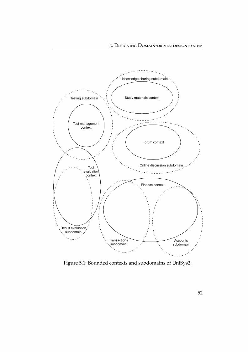
5. Designing Domain-driven design system
Testing subdomain
Test managementcontext
Online discussion subdomain
Forum context
Result evaluationsubdomain
Testevaluation
context
Finance context
Knowledge sharing subdomain
Study materials context
Transactionssubdomain
Accountssubdomain
Figure 5.1: Bounded contexts and subdomains of UniSys2.
52
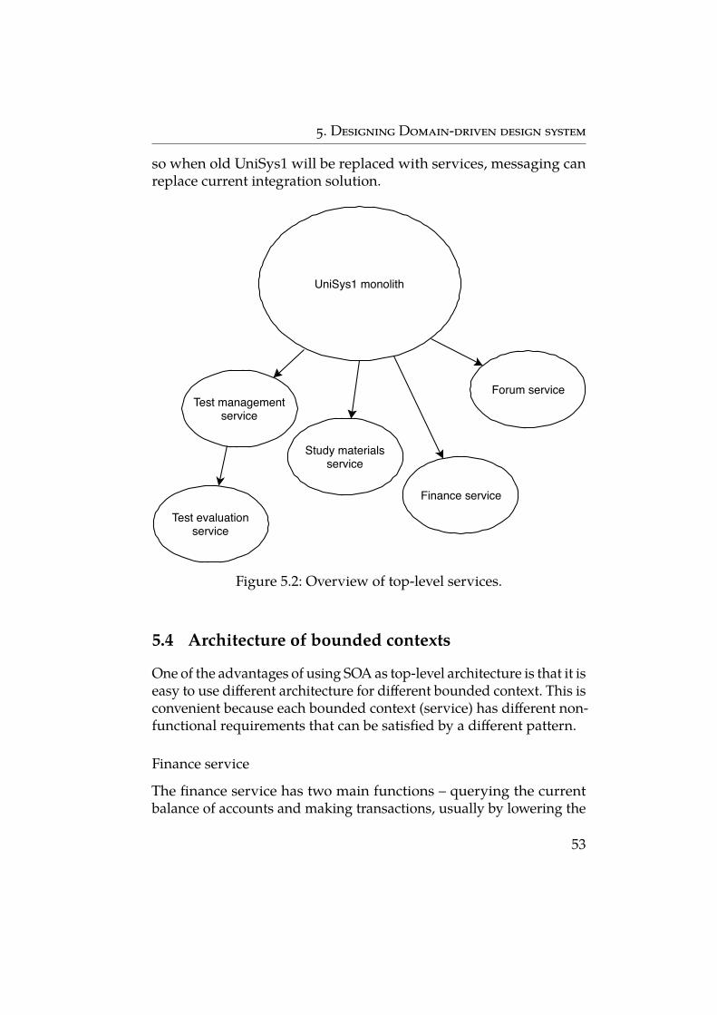
5. Designing Domain-driven design system
so when old UniSys1 will be replaced with services, messaging canreplace current integration solution.
UniSys1 monolith
Test managementservice
Test evaluationservice
Study materialsservice
Forum service
Finance service
Figure 5.2: Overview of top-level services.
5.4 Architecture of bounded contexts
One of the advantages of using SOA as top-level architecture is that it iseasy to use different architecture for different bounded context. This isconvenient because each bounded context (service) has different non-functional requirements that can be satisfied by a different pattern.
Finance service
The finance service has two main functions – querying the currentbalance of accounts and making transactions, usually by lowering the
53
5. Designing Domain-driven design system
balance of a student or a user who purchased something. Because theseare two separate functions, one writes and one reads, the architectdecided to use CQRS, which will split the system into two part – one forwriting (transferring money) and one for reading (querying accountbalance).
Because the architect saw that most of the actions happening in thesystem nicely fit with the event-driven model, he decided to use Eventsourcing pattern for write part of the service. This will nicely representthe transaction domain as a sequence of events for manipulation withaccounts, which is basically the same how transactions are viewed bydomain experts. Furthermore, event sourcing has the potential to pro-vide additional business value. Even though in UniSys2 university didnot request any analytics, in the future they might consider analyzingtransactions to provide better targeting of services for students andemployees. This will be easier to do with event sourcing architecturebecause it saves all the events that happened in the system, which canbe used to build different view models for different analytic queries.
Event sourcing stores events in an event store in a raw format.Therefore it isn’t possible to query the store to get information (such asaccount balance) directly. As a result of this, a separate read databasewill be created which will be updated by event handlers every time anew event is issued. This database can be then directly used by theread side of the service.
Because there are two databases now, it is necessary to keep themconsistent. There are two options – strong consistency and eventualconsistency. Strong consistency is achieved by updating the event storeand read database under one transaction. The advantage is that theread database is updated immediately and the result is immediatelyvisible (for example in GUI). The disadvantage is the increased transac-tional boundary. Two databases need to be updated in one transactionand immediately, which decreases the throughput of the write side –it is possible to perform fewer payments in a time period. Eventualconsistency makes the read database consistent only eventually, so itis not updated in the same transaction. This increases the throughputof payment handling, but the result is not immediately visible in theuser interface. This can be often confusing for a user.
In the end, the architect decided to use eventual consistency be-cause the high throughput of payments is an important requirement.
54
5. Designing Domain-driven design system
The architect assessed that in this case, it is not crucial for a user tosee the immediate result. Usually, he will pay with student card so hecannot even notice the delay, which in most cases will be less than asecond anyway.
Test evaluation service
The main focus of the test evaluation service is to evaluate answers ofa test. This can be easy an evaluation such as checking if the correctoption was chosen but also complicated evaluation such as correctinggrammar mistakes or evaluating programming code. Evaluating willhappen typically in steps. Simple questions will usually need just onestep, but, for example, performing static analysis on a programmingcode to test if a student abides by coding principles will happen inmultiple steps – step for checking naming conventions, method lengthsetc.
To make the evaluation more flexible, the architect decided to usePipes and filters pattern. Each evaluation step will be encapsulated ina separate filter. Filters of related evaluations will be joined by the pipe.The whole evaluation will be performed as running of all pipelines fora given test. The added flexibility is conveyed in the possibility to builddifferent pipelines for different types of tests. It makes the service alsoeasily extensible – to add a new evaluation step, it is enough to add anew filter and add it to the desired pipelines.
Test management service
For this service, the architect decided to not use any specific archi-tectural pattern. He assessed that writing and reading logic is notseparate enough for CQRS to be useful. He also considered Eventsourcing, but he did not think that the model is event-oriented. Mostof the objects do not change their state very much. He found that ifthe objects were represented as sequences of events, there is very littlepotential business gain from event logs. It was obvious that pipes andfilters is not a suitable pattern because the logic of the service does notfit the paradigm of chained processing steps. IDesign could be used tofurther decompose the service into components, but the service is notcomplex enough to make it worth the effort. In the end, the architect
55
5. Designing Domain-driven design system
was deciding between hexagonal and layered architecture. Becausehe wanted to focus on the domain logic and make it infrastructureindependent, he decided to use hexagonal architecture which allowsthis by abiding by the dependency inversion principle.
Study materials service
The study materials service provides two main functions – adding ofstudy materials by teachers and downloading of study materials bystudents. The architect noticed that the two parts are quite separate,so he decided to use CQRS. This will make reading and writing moreindependent, and it will enable to optimize both parts independently.It can be convenient for the reading part which will be used muchmore. However, because the service is fairly simple, with a simplemodel, the architect did not use any other complicated pattern likeEvent sourcing. Both read and write parts will have only simple layersto separate user interface and business logic.
Forum service
For the forum service, the architect decided to use existing, boughtsolution. University doesn’t need a custom, special forum, they needjust a typical subsystem for discussions with topics and responses. Tonot make other parts of the system dependant on API of 3rd partycomponent, the architect still decided to encapsulate the componentin a service. The service will serve as an open host service defining theclear, independent contract of the forum functionality. Furthermore,the service will have published language which will be in ubiquitouslanguage, and it will be closer to domains concepts than 3rd partylanguage.
56
6 Conclusion
This thesis focused on Domain-driven design and architectural pat-terns. Following a brief introduction to DDD, we analyzed architec-tural patterns and styles considered at the levels of domain logic,bounded context and the entire system.
For the domain logic, the domain model provides the best optionswhen applying DDD. On the bounded context level, many differ-ent patterns could be used, depending on the domain. For a typicaldomain, either layered architecture (for simple bounded context) orhexagonal architecture will typically be implemented. More specificdomains can fit CQRS, event sourcing or pipes and filters patterns.For an entire system, two options were described – monolithic andservice-oriented architecture. Monolithic architecture was assessed tobe a better option for simpler systems with not many bounded con-texts and service-oriented architecture for more complex systems withbounded contexts where each could have a custom architecture. Totie it all together, four integration styles were described – file transfer,shared database, remote procedure invocation and messaging, fromwhich remote procedure invocation or messaging are the best options.
In the end, an exemplary system was designed on which it wasshown how domain and non-functional requirements could drive theselection of an architectural pattern.
6.1 Future work
The thesis focused mainly on the theory of the patterns and Domain-driven design. One of the possible extensions of this thesis can be theextensive research of the usage of the architectural patterns with DDDin the real-life systems and the assessment which patterns worked thebest with DDD and managed to help to reach its goals.
Another extension could be the expansion of the examined patternswith a focus on less common patterns to describe them similarly tothose presented in this thesis.
57
Bibliography
1. EVANS, Eric. Domain-Driven Design: Tackling Complexity in the Heartof Software. Addison-Wesley, 2004.
2. VERNON, Vaughn. Implementing Domain-Driven Design. Addison -Wesley, 2014.
3. MILLET, Scott; TUNE, Nick. Patterns, Principles, and Practices of Domain-Driven Design. Wrox, 2015.
4. ROUSE, Margaret. waterfall model [online]. 2007 [visited on 2018-09-12].Available also from: https://searchsoftwarequality.techtarget.com/definition/waterfall-model.
5. GAMMA, Erich; HELM, Richard; JOHNSON, Ralph; VLISSIDES, John.Design Patterns: Elements of Reusable Object-Oriented Software. Addi-son - Wesley, 1994.
6. FOWLER, Martin. Patterns of Enterprise Application Architecture. Addi-son - Wesley, 2002.
7. FOWLER, Martin. AnemicDomainModel [online]. 2003 [visited on 2018-11-24]. Available also from: https : / / www . martinfowler . com /bliki/AnemicDomainModel.html.
8. FOOTE, Brian; YODER, Joseph. Big Ball of Mud [Fourth Conference onPatterns Languages of Programs (PLoP ’97/EuroPLoP ’97)]. 1997.
9. RAJ, Pethuru; RAMAN, Anupama; SUBRAMANIAN, Harihara. Ar-chitectural Patterns. Packt Publishing, 2017.
10. BUSCHMANN, Frank; MEUNIER, Regine; ROHNERT, Hans; SOM-MERLAD, Peter; STAL, Michael. Pattern-Oriented Software Architec-ture. Wiley, 1996.
11. MARTIN, Robert C. Agile Software Development, Principles, Patterns,and Practices. Pearson, 2002.
12. PALERMO, Jeffrey. The Onion Architecture [online]. 2008 [visited on2018-10-07]. Available also from: https://jeffreypalermo.com/2008/07/the-onion-architecture-part-1/.
13. LÖWY, Juval. Zen of Architecture [online]. 2013 [visited on 10.10.2018].Available also from: https://youtu.be/Jxm2rgeuC6s.
58
BIBLIOGRAPHY
14. YOUNG, Greg. CQRS, Task Based UIs, Event Sourcing agh! [online].2010 [visited on 2018-10-19]. Available also from: http://codebetter.com / gregyoung / 2010 / 02 / 16 / cqrs - task - based - uis - event -sourcing-agh/.
15. YOUNG, Greg. CQRS Class [online]. 2012 [visited on 2018-10-19].Available also from: https://www.youtube.com/watch?v=whCk1Q87_ZI.
16. FOWLER, Martin. CQRS [online]. 2011 [visited on 2018-10-19]. Avail-able also from: https://martinfowler.com/bliki/CQRS.html.
17. FOWLER, Martin. Event Sourcing [online]. 2011 [visited on 2018-11-13]. Available also from: https : / / martinfowler . com / eaaDev /EventSourcing.html.
18. ROUSE, Margaret. monolithic architecture [online]. 2016 [visited on2019-01-15]. Available also from: https://whatis.techtarget.com/definition/monolithic-architecture.
19. FOWLER, Martin. MonolithFirst [online]. 2015 [visited on 2019-01-15]. Available also from: https : / / martinfowler . com / bliki /MonolithFirst.html.
20. ERL, Thomas. SOA Design Patterns. Prentice Hall, 2013.21. FOWLER, Martin. ServiceOrientedAmbiguity [online]. 2005 [visited on
2019-01-04]. Available also from: https : / / martinfowler . com /bliki/ServiceOrientedAmbiguity.html.
22. BELL, Michael. Service-Oriented Modeling: Service Analysis, Design, andArchitecture. Wiley, 2008.
23. ROTEM-GAL-OZ, Arnon. SOA Patterns. Manning Publications, 2012.24. FOWLER, Martin; LEWIS, James. Microservices [online]. 2014 [visited
on 2019-01-13]. Available also from: https://martinfowler.com/articles/microservices.html.
25. ERL, Thomas. SOA: Principles of Service Design. Prentice Hall, 2007.26. HOHPE, Gregor; WOOLF, Bobby. Enterprise Integration Pattern. Addi-
son - Wesley, 2004.
59
BIBLIOGRAPHY
27. ARPACI-DUSSEAU, Remzi H.; ARPACI-DUSSEAU, Andrea C. Intro-duction to Distributed Systems [online]. 2014 [visited on 2019-03-10].Available also from: http://pages.cs.wisc.edu/~remzi/OSTEP/dist-intro.pdf.
28. DAIGNEAU, Robert. Service design patterns. Addison-Wesley, 2012.29. RICHARDSON, Chris. Pattern: Remote Procedure Invocation (RPI) [on-
line]. 2018 [visited on 2019-03-10]. Available also from: https://microservices.io/patterns/communication-style/rpi.html.
60

Attachments
∙ UniSys2-architecture.pdf
– Diagrams showing the architecture of the designed systemfrom the chapter 5.
∙ diagrams.zip
– Diagrams from this thesis in editable form.
61


