Embed Size (px)
Citation preview
Grant Agreement number: 288899
Project acronym: Robot-Era
Project title: Implementation and integration of advanced Robotic systems and intelligent Environments in real scenarios for ageing population
Funding scheme: Large-scale integrating project (IP)
Call identifier: FP7-ICT-2011.7
Challenge: 5 – ICT for Health, Ageing Well, Inclusion and Governance
Objective: ICT-2011.5.4 ICT for Ageing and Wellbeing
Project website address: www.robot-era.eu
D4.3
Final Domestic robotic platform prototype for the second experimental loop
Due date of deliverable: 31/08/2014Actual submission date: 16/12/2014
Start date of project: 01/01/2012 Duration: 48 months
Organisation name of lead contractor for this deliverable: UHAMDeliverable author: N. Hendrich, H. Bistry, F. Cavallo, T. Langner
Version: [1.]
Project co-funded by the European Commission within the Seventh Framework Programme (2007-2013)
Dissemination LevelPU Public XPP Restricted to other programme participants (including the Commission Service)
RE Restricted to a group specified by the consortium (including the Commission Service)CO Confidential, only for members of the consortium (including the Commission Service)
Revision History
Date Rev. Change Author
2015.01.31 1.4 updated for 2015.02 Peccioli integration week N. Hendrich
2015.01.21 1.3 description of new design and cover I. Mannari
2014.12.22 1.2 updates after 2014.12 Angen integration week H. Bistry
2014.12.18 1.1 document exekutor/action_exekutor and the meta-tuples PEIS interface
N. Hendrich
2014.12.15 1.0 revision and final version for submission N. Hendrich
2014.11.08 0.4 revision after Ancona meeting N. Hendrich
2014.08.31 0.3 updates for initial submission N. Hendrich
2014.06.02 0.2 track changes from D2.6 and D2.8 H. Bistry
2014.04.01 0.1 created N. Hendrich
Future Updates
This handbook documents the current state of the Robot-Era Domestic Robot including allmain aspects of the robot hardware, software, and the integrating services architecture withconnection to the PEIS middleware at the time of writing. Future updates and developmentsare expected to track the experiences gained with the robot during the second experimentalphase of the project. Updated releases of the handbook will be uploaded to the projectrepository as the software and services evolve.
ii
Contents
Executive Summary 1
1 Overview 3
2 Hardware 72.1 Concept and General Robot Design . . . . . . . . . . . . . . . . . . . . . 72.2 Updated design for the second experimental loop . . . . . . . . . . . . . . 8
2.2.1 New robot cover and design changes . . . . . . . . . . . . . . . . . 82.2.2 Tilting handle . . . . . . . . . . . . . . . . . . . . . . . . . . . . . 112.2.3 Updated sensors and computers . . . . . . . . . . . . . . . . . . . 12
2.3 SCITOS G5 platform . . . . . . . . . . . . . . . . . . . . . . . . . . . . . 132.3.1 SCITOS-G5 mobile advanced . . . . . . . . . . . . . . . . . . . . 132.3.2 Sick S300 safety laser-scanner . . . . . . . . . . . . . . . . . . . . 142.3.3 Hokuyo URG-04LX laser-scanner . . . . . . . . . . . . . . . . . . 142.3.4 Ultrasonic sensor ring . . . . . . . . . . . . . . . . . . . . . . . . 142.3.5 Platform mounted camera . . . . . . . . . . . . . . . . . . . . . . 14
2.4 Kinova Jaco manipulator . . . . . . . . . . . . . . . . . . . . . . . . . . . 152.4.1 Kinova Joystick . . . . . . . . . . . . . . . . . . . . . . . . . . . . 15
2.5 Sensor head . . . . . . . . . . . . . . . . . . . . . . . . . . . . . . . . . . 162.5.1 Asus XtionPro . . . . . . . . . . . . . . . . . . . . . . . . . . . . 162.5.2 Camera DFK 31BF03 . . . . . . . . . . . . . . . . . . . . . . . . 162.5.3 Camera DFK 21BF04 . . . . . . . . . . . . . . . . . . . . . . . . 162.5.4 Directed Perception D46 pan-tilt unit . . . . . . . . . . . . . . . . 16
2.6 Human-Robot interface . . . . . . . . . . . . . . . . . . . . . . . . . . . . 172.6.1 Tablet-based Interface . . . . . . . . . . . . . . . . . . . . . . . . 172.6.2 Teleoperation Interface . . . . . . . . . . . . . . . . . . . . . . . . 172.6.3 Tilting Handle for Walking Support . . . . . . . . . . . . . . . . . 17
2.7 Safety Features . . . . . . . . . . . . . . . . . . . . . . . . . . . . . . . . 182.7.1 Emergency-stop switches . . . . . . . . . . . . . . . . . . . . . . . 182.7.2 Bumper ring . . . . . . . . . . . . . . . . . . . . . . . . . . . . . 182.7.3 Safety laser scanner . . . . . . . . . . . . . . . . . . . . . . . . . . 18
2.8 Workspace analysis . . . . . . . . . . . . . . . . . . . . . . . . . . . . . . 19
3 Software 213.1 Overview . . . . . . . . . . . . . . . . . . . . . . . . . . . . . . . . . . . 21
3.1.1 ROS . . . . . . . . . . . . . . . . . . . . . . . . . . . . . . . . . . 243.1.2 Domestic Robot URDF . . . . . . . . . . . . . . . . . . . . . . . . 273.1.3 Coordinate-systems and tf . . . . . . . . . . . . . . . . . . . . . . 283.1.4 Launching the domestic robot . . . . . . . . . . . . . . . . . . . . 313.1.5 Running ROS on Multiple Computers . . . . . . . . . . . . . . . . 363.1.6 Teleoperation interface . . . . . . . . . . . . . . . . . . . . . . . . 373.1.7 Control center teleoperation interface . . . . . . . . . . . . . . . . 383.1.8 Robot calibration . . . . . . . . . . . . . . . . . . . . . . . . . . . 39
3.2 Robot localization and navigation . . . . . . . . . . . . . . . . . . . . . . 40
iii
3.2.1 MIRA . . . . . . . . . . . . . . . . . . . . . . . . . . . . . . . . . 403.2.2 Cognidrive . . . . . . . . . . . . . . . . . . . . . . . . . . . . . . 413.2.3 MIRA-ROS bridge . . . . . . . . . . . . . . . . . . . . . . . . . . 43
3.3 Sensing and Perception . . . . . . . . . . . . . . . . . . . . . . . . . . . . 473.3.1 Overview . . . . . . . . . . . . . . . . . . . . . . . . . . . . . . . 473.3.2 Pan-Tilt Unit . . . . . . . . . . . . . . . . . . . . . . . . . . . . . 473.3.3 Camera System and Image Processing . . . . . . . . . . . . . . . . 473.3.4 XtionPro RGB-D Camera and Point-Clouds . . . . . . . . . . . . . 523.3.5 MJPEG-Server 2 . . . . . . . . . . . . . . . . . . . . . . . . . . . 523.3.6 Object Detection and Pose Estimation . . . . . . . . . . . . . . . . 543.3.7 Visionhub . . . . . . . . . . . . . . . . . . . . . . . . . . . . . . . 543.3.8 SIFT-based object recognition . . . . . . . . . . . . . . . . . . . . 563.3.9 AprilTag Marker detection . . . . . . . . . . . . . . . . . . . . . . 583.3.10 Tabletop segmentation . . . . . . . . . . . . . . . . . . . . . . . . 593.3.11 Human Detection and Recognition . . . . . . . . . . . . . . . . . . 60
3.4 Manipulation . . . . . . . . . . . . . . . . . . . . . . . . . . . . . . . . . 623.5 Kinova Jaco API and ROS-node . . . . . . . . . . . . . . . . . . . . . . . 63
3.5.1 Jaco DH-parameters and specifications . . . . . . . . . . . . . . . 633.5.2 Jaco Joystick and teleoperation . . . . . . . . . . . . . . . . . . . . 633.5.3 Jaco .NET API . . . . . . . . . . . . . . . . . . . . . . . . . . . . 643.5.4 Jaco ROS integration . . . . . . . . . . . . . . . . . . . . . . . . . 673.5.5 Jaco gripper . . . . . . . . . . . . . . . . . . . . . . . . . . . . . . 703.5.6 Inverse Kinematics . . . . . . . . . . . . . . . . . . . . . . . . . . 713.5.7 Traps and Pitfalls . . . . . . . . . . . . . . . . . . . . . . . . . . . 723.5.8 Collision map processing . . . . . . . . . . . . . . . . . . . . . . . 72
3.6 MoveIt! framework . . . . . . . . . . . . . . . . . . . . . . . . . . . . . . 733.7 Manipulation Action Server . . . . . . . . . . . . . . . . . . . . . . . . . 773.8 Manipulation Tasks in Robot-Era Scenarios . . . . . . . . . . . . . . . . . 78
3.8.1 Domestic to Condominium Object Exchange . . . . . . . . . . . . 783.8.2 Basket objects . . . . . . . . . . . . . . . . . . . . . . . . . . . . 803.8.3 Cleaning Tasks . . . . . . . . . . . . . . . . . . . . . . . . . . . . 803.8.4 Object Handover Tasks . . . . . . . . . . . . . . . . . . . . . . . . 81
3.9 Robot Watchdog . . . . . . . . . . . . . . . . . . . . . . . . . . . . . . . 843.10 Simulation . . . . . . . . . . . . . . . . . . . . . . . . . . . . . . . . . . . 86
3.10.1 Domestic robot in Gazebo . . . . . . . . . . . . . . . . . . . . . . 873.10.2 Notes and version compatibility . . . . . . . . . . . . . . . . . . . 88
3.11 PEIS Integration . . . . . . . . . . . . . . . . . . . . . . . . . . . . . . . . 903.11.1 PEIS-ROS TupleHandler architecture . . . . . . . . . . . . . . . . 903.11.2 Using actionlib and feedback functions . . . . . . . . . . . . . . . 903.11.3 Synchronization . . . . . . . . . . . . . . . . . . . . . . . . . . . 913.11.4 Structured data . . . . . . . . . . . . . . . . . . . . . . . . . . . . 933.11.5 Writing a new TupleHandler . . . . . . . . . . . . . . . . . . . . . 933.11.6 ActionExekutor . . . . . . . . . . . . . . . . . . . . . . . . . . . . 94
iv
4 Services 994.1 Low-Level Services . . . . . . . . . . . . . . . . . . . . . . . . . . . . . . 100
4.1.1 EmergencyStop . . . . . . . . . . . . . . . . . . . . . . . . . . . . 1014.1.2 GetCameraImage . . . . . . . . . . . . . . . . . . . . . . . . . . . 1024.1.3 GetKinectImage . . . . . . . . . . . . . . . . . . . . . . . . . . . 1034.1.4 GetLaserScan . . . . . . . . . . . . . . . . . . . . . . . . . . . . . 1044.1.5 GetSonarScan . . . . . . . . . . . . . . . . . . . . . . . . . . . . . 1054.1.6 MoveTo . . . . . . . . . . . . . . . . . . . . . . . . . . . . . . . . 1064.1.7 Dock and Undock . . . . . . . . . . . . . . . . . . . . . . . . . . 1074.1.8 MovePtu . . . . . . . . . . . . . . . . . . . . . . . . . . . . . . . 1084.1.9 RetractJacoArm . . . . . . . . . . . . . . . . . . . . . . . . . . . . 1094.1.10 ParkJacoArm . . . . . . . . . . . . . . . . . . . . . . . . . . . . . 1104.1.11 MoveJacoArm . . . . . . . . . . . . . . . . . . . . . . . . . . . . 1114.1.12 MoveJacoCartesian . . . . . . . . . . . . . . . . . . . . . . . . . . 1124.1.13 MoveitJacoCartesian . . . . . . . . . . . . . . . . . . . . . . . . . 1134.1.14 MoveJacoFingers . . . . . . . . . . . . . . . . . . . . . . . . . . . 114
4.2 Intermediate Services . . . . . . . . . . . . . . . . . . . . . . . . . . . . . 1154.2.1 DetectKnownObject . . . . . . . . . . . . . . . . . . . . . . . . . 1164.2.2 DetectUnknownObject . . . . . . . . . . . . . . . . . . . . . . . . 1174.2.3 GraspAndLiftKnownObject . . . . . . . . . . . . . . . . . . . . . 1184.2.4 SideGraspAndLiftObject . . . . . . . . . . . . . . . . . . . . . . . 1194.2.5 TopGraspAndLiftObject . . . . . . . . . . . . . . . . . . . . . . . 1204.2.6 PlaceObjectOnTray . . . . . . . . . . . . . . . . . . . . . . . . . . 1214.2.7 PlaceObject . . . . . . . . . . . . . . . . . . . . . . . . . . . . . . 1224.2.8 DropObject . . . . . . . . . . . . . . . . . . . . . . . . . . . . . . 1234.2.9 GraspObjectFromTray . . . . . . . . . . . . . . . . . . . . . . . . 1244.2.10 HandoverObjectToUser . . . . . . . . . . . . . . . . . . . . . . . . 1254.2.11 HandoverObjectFromUser . . . . . . . . . . . . . . . . . . . . . . 1264.2.12 PourLiquidMotion . . . . . . . . . . . . . . . . . . . . . . . . . . 1274.2.13 MoveHingedDoor . . . . . . . . . . . . . . . . . . . . . . . . . . 1284.2.14 LookAt . . . . . . . . . . . . . . . . . . . . . . . . . . . . . . . . 1294.2.15 DetectPerson . . . . . . . . . . . . . . . . . . . . . . . . . . . . . 1304.2.16 TrackPerson . . . . . . . . . . . . . . . . . . . . . . . . . . . . . 1314.2.17 RecognizePerson . . . . . . . . . . . . . . . . . . . . . . . . . . . 132
4.3 High-level Services . . . . . . . . . . . . . . . . . . . . . . . . . . . . . . 1334.3.1 WalkingSupport . . . . . . . . . . . . . . . . . . . . . . . . . . . 1344.3.2 SwipeSurfaceService . . . . . . . . . . . . . . . . . . . . . . . . . 1354.3.3 CleanFloorService . . . . . . . . . . . . . . . . . . . . . . . . . . 1374.3.4 CleanWindowService . . . . . . . . . . . . . . . . . . . . . . . . . 1384.3.5 CleanTableService . . . . . . . . . . . . . . . . . . . . . . . . . . 1394.3.6 BringFoodService . . . . . . . . . . . . . . . . . . . . . . . . . . 1404.3.7 CarryOutGarbage . . . . . . . . . . . . . . . . . . . . . . . . . . . 1414.3.8 LaundryService . . . . . . . . . . . . . . . . . . . . . . . . . . . . 142
v
5 Software installation and setup 1435.1 Ubuntu 12.04 and ROS Hydro . . . . . . . . . . . . . . . . . . . . . . . . 1435.2 Software Installation Paths . . . . . . . . . . . . . . . . . . . . . . . . . . 1435.3 MIRA and CogniDrive . . . . . . . . . . . . . . . . . . . . . . . . . . . . 1445.4 PEIS . . . . . . . . . . . . . . . . . . . . . . . . . . . . . . . . . . . . . . 1445.5 Kinova Jaco Software . . . . . . . . . . . . . . . . . . . . . . . . . . . . . 1455.6 ROS Hydro . . . . . . . . . . . . . . . . . . . . . . . . . . . . . . . . . . 1455.7 GStreamer Libraries . . . . . . . . . . . . . . . . . . . . . . . . . . . . . . 1465.8 Robot-Era ROS stack . . . . . . . . . . . . . . . . . . . . . . . . . . . . . 1465.9 Network Setup and Wired/Wifi Bridge . . . . . . . . . . . . . . . . . . . . 1475.10 Remote Roslaunch Setup . . . . . . . . . . . . . . . . . . . . . . . . . . . 1495.11 Robot calibration . . . . . . . . . . . . . . . . . . . . . . . . . . . . . . . 152
6 Summary 153
References 154
vi
List of Figures
1 Domestic dobot prototype . . . . . . . . . . . . . . . . . . . . . . . . . . . 42 Designer concept of the Domestic robot . . . . . . . . . . . . . . . . . . . 73 Sketch of the domestic robot with handle . . . . . . . . . . . . . . . . . . . 84 Updated design of Domestic robot . . . . . . . . . . . . . . . . . . . . . . 95 Updated color scheme . . . . . . . . . . . . . . . . . . . . . . . . . . . . . 106 New soft headgear . . . . . . . . . . . . . . . . . . . . . . . . . . . . . . 117 Updated tilting driving handle . . . . . . . . . . . . . . . . . . . . . . . . 118 Updated Scitos-G5 platform . . . . . . . . . . . . . . . . . . . . . . . . . 129 Jaco arm and gripper . . . . . . . . . . . . . . . . . . . . . . . . . . . . . 1510 Robot arms evaluated for the Domestic robot . . . . . . . . . . . . . . . . 1911 Arm workspace analysis . . . . . . . . . . . . . . . . . . . . . . . . . . . 1912 Software Architecture of the domestic robot . . . . . . . . . . . . . . . . . 2213 Robot-Era ROS stacks and packages . . . . . . . . . . . . . . . . . . . . . 2614 URDF of the domestic robot . . . . . . . . . . . . . . . . . . . . . . . . . 2715 Coordinate frames of the domestic robot . . . . . . . . . . . . . . . . . . . 2916 Base coordinate frames of the domestic robot . . . . . . . . . . . . . . . . 3017 Coordinate frame graph of the domestic robot . . . . . . . . . . . . . . . . 3018 Default rviz configuration . . . . . . . . . . . . . . . . . . . . . . . . . . . 3519 Sony Sixaxis joystick . . . . . . . . . . . . . . . . . . . . . . . . . . . . . 3720 MIRA-Center . . . . . . . . . . . . . . . . . . . . . . . . . . . . . . . . . 4421 ROS-Cognidrive bridge . . . . . . . . . . . . . . . . . . . . . . . . . . . . 4522 Updated perception pipeline . . . . . . . . . . . . . . . . . . . . . . . . . 4823 Object Coordinate Systems . . . . . . . . . . . . . . . . . . . . . . . . . . 5524 Object manipulation scene . . . . . . . . . . . . . . . . . . . . . . . . . . 5725 Visualization of detected objects . . . . . . . . . . . . . . . . . . . . . . . 5726 AprilTag marker detection . . . . . . . . . . . . . . . . . . . . . . . . . . 5927 SVM-based people detection . . . . . . . . . . . . . . . . . . . . . . . . . 6128 Person detection and recognition . . . . . . . . . . . . . . . . . . . . . . . 6129 Jaco arm home and retract positions . . . . . . . . . . . . . . . . . . . . . 6430 Jaco finger positions vs. object size . . . . . . . . . . . . . . . . . . . . . . 7031 MoveIt! overview . . . . . . . . . . . . . . . . . . . . . . . . . . . . . . . 7432 Reference objects . . . . . . . . . . . . . . . . . . . . . . . . . . . . . . . 7833 Doro-Coro object exchange . . . . . . . . . . . . . . . . . . . . . . . . . . 7934 Grasping the basket object . . . . . . . . . . . . . . . . . . . . . . . . . . 8035 Setup for cleaning tasks . . . . . . . . . . . . . . . . . . . . . . . . . . . . 8136 Robot-to-human object handover . . . . . . . . . . . . . . . . . . . . . . . 8237 States in robot-to-human object handover . . . . . . . . . . . . . . . . . . 8338 Multi-robot simulation in Gazebo . . . . . . . . . . . . . . . . . . . . . . 8639 Visualization of multi-robot simulation . . . . . . . . . . . . . . . . . . . . 8740 Gazebo simulator architecture . . . . . . . . . . . . . . . . . . . . . . . . 8841 Actionlib client-server interface . . . . . . . . . . . . . . . . . . . . . . . 9142 ROS actionlib states . . . . . . . . . . . . . . . . . . . . . . . . . . . . . . 9243 tuple_handler.h . . . . . . . . . . . . . . . . . . . . . . . . . . . . . . . . 9544 DemoService.h . . . . . . . . . . . . . . . . . . . . . . . . . . . . . . . . 96
vii
45 DemoService.cc (1/2) . . . . . . . . . . . . . . . . . . . . . . . . . . . . . 9646 DemoService.cc (2/2) . . . . . . . . . . . . . . . . . . . . . . . . . . . . . 9747 PEIS exekutor meta-tuples . . . . . . . . . . . . . . . . . . . . . . . . . . 9848 Software installation paths . . . . . . . . . . . . . . . . . . . . . . . . . . 14449 On-board computer network . . . . . . . . . . . . . . . . . . . . . . . . . 14750 Example network setup file with WiFi/wired Ethernet bridge. . . . . . . . . 14851 Example env.sh environment file for remote roslaunch. . . . . . . . . . . . 15152 Example roslaunch machine definitions and usage. . . . . . . . . . . . . . 151
viii
D4.3 - Domestic Robot Handbook 2014
Executive Summary
This robot handbook is part of the public deliverable Final Domestic robotic platform pro-totype for the second experimental loop (D4.3) of the European integrated research projectRobot-Era, www.robot-era.eu. It documents the hardware, software, and services architec-ture of the Domestic Robot, a state-of-the-art indoor service robot designed to help elderlypeople with their daily activities. Together with the companion reports of the project (D3.3,D3.4, D5.3, and D6.3), the document describes the robot systems and ambient intelligencearchitecture to be used in the upcoming second experimental phase of the project.
The report is a revised and extended version of the original robot handbook D4.2 [58].Based on user-feedback and experiences gained during the first experimental phase of theproject in 2013, several S/T requirements were identified and documented in deliverableD2.8 [52]. The corresponding changes and improvements have all been implemented. Theresult is a more capable and more robust robot platform for the real end-users tests.
Hardware updates
• redesiged and improved outer appearance of the robot, motivated by analysis of theuser-acceptance during the first experimental loop,
• minor hardware changes to improve robot capabilities, including updated arm andmain-pillar positions and larger object transportation tray,
• additional sensors for manipulation tasks and robot docking,
• additional on-board computers for better performance.
Notable software improvements
• improved HRI and speech manager, see D5.3 [60],
• meta-tuples based PEIS interface (“exekutor”), see D3.4 [56],
• multi-modal object perception, combining PCL, SIFT, and AprilTags,
• Kinect-based human tracking to complement the AmI user tracking,
• sensor-based robot to human object handover capability,
• collision-aware object manipulation base on the MoveIt! framework.
Improved Robot-Era services
• additional robot services implemented and exported to PEIS,
• reconfiguration of services using meta-tuples,
• Doro/Coro object exchange using custom objects and basket,
• improved implementation of laudry and object transportation tasks,
• initial version of cleaning tasks,
• services regression testing using multi-robot Gazebo simulation.
1

D4.3 - Domestic Robot Handbook 2014
2
D4.3 - Domestic Robot Handbook 2014
1 Overview
This handbook summarizes the updated hardware, software, and service architecture of theDomestic Robot, short doro, of project Robot-Era. The report is a revised and extendedversion of the original robot handbook D4.2 [58]. It documents the changes made to therobot hardware and software based on the experiences gained during the first experimentalloop of the project. For convenience, those parts of the text that have been added or aresignificantly changed are marked by vertical bars in the margin of the document.
Together with the companion reports D3.4 (ambient intelligence) [56], D5.3 (condominiumrobot) [60], and D6.3 (outdoor robot) [61], this handbook documents the overall system tobe used and tested during the upcoming second experimental loop of the Robot-Era project.
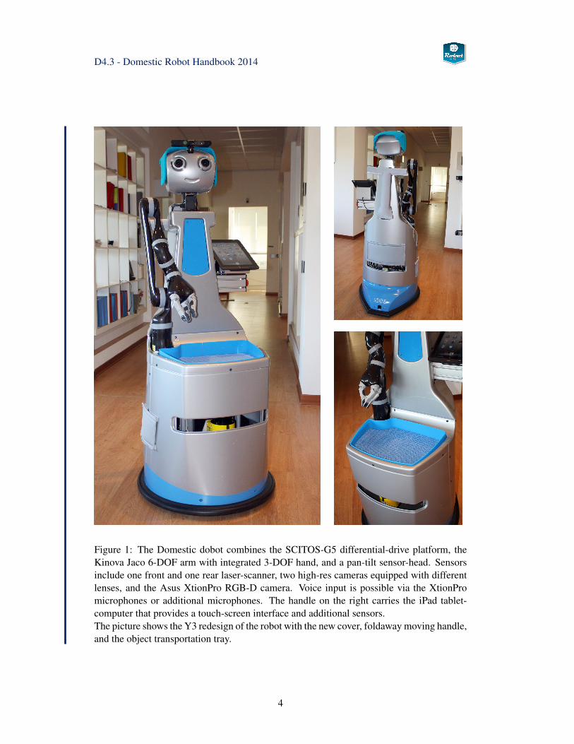
See Fig. 1 on page 4 for a photo of the updated robot prototype. Only minor changes weremade to the basic robot hardware. The main pillar with the head was moved backwards abit to make room for the transport tray on the robot and the mount position of the arm waschanged slightly. A new cover was designed for the robot based on user-feedback collectedduring the first experimental loop. The overall software architecture remains unchanged, butseveral improvements have been integrated to track developements of the ROS and MIRAframeworks, and to improve robustness of the robot. Most of the development effort hasconcentrated on refining and implementation of the end-user driven services provided bythe robot.
Please visit the project website at www.robot-era.eu for details about the Robot-Era projectand its background and goals. The core objective of the Robot-Era project is to improvethe quality of life and the efficency of care for elderly people via a set of advanced roboticservices. Going beyond the traditional concept of a single standalone robot, the project con-siders a set of different robots operating in a sensor-equipped intelligent environment, orsmart home. Besides the actual design and implemention of the robot services, the projectalso monitors the feasibility, scientific/technical effectiveness and the social and legal plau-sibiliy and acceptability by the end-users.
Three robot prototypes are developed in the context of the project, each targeting differentscenarios identified as relevant for the end-users in the initial phase of the project. Theoutdoor robot provides transportation, guidance, walking support and surveillance services,and the services of the condominium robot center around transportation tasks. The domesticrobot is a classical indoor service robot equipped with advanced sensors for environmentperception and a robot arm and gripper to manipulate household objects.
As described in chapter 3.1, the overall software architecture for the Robot-Era services con-sists of several layers, where the PEIS system provides the ambient intelligence (AmiI) thatmanages the sensor-network and the different robots in the system. The end-user requestsservices from the whole system, which implies that no advanced human-robot interface isrequired for the domestic or condominium robots. Details of the AmI layer and softwarehave been documented in the project reports D3.1, D3.2, and D3.3 [53, 54, 56].
3
D4.3 - Domestic Robot Handbook 2014
Figure 1: The Domestic dobot combines the SCITOS-G5 differential-drive platform, theKinova Jaco 6-DOF arm with integrated 3-DOF hand, and a pan-tilt sensor-head. Sensorsinclude one front and one rear laser-scanner, two high-res cameras equipped with differentlenses, and the Asus XtionPro RGB-D camera. Voice input is possible via the XtionPromicrophones or additional microphones. The handle on the right carries the iPad tablet-computer that provides a touch-screen interface and additional sensors.The picture shows the Y3 redesign of the robot with the new cover, foldaway moving handle,and the object transportation tray.
4
D4.3 - Domestic Robot Handbook 2014
Outline
This report is part of the public project deliverable D4.3, which consists of the actual domes-tic robot prototype, and provides the tutorial and handbook information about the physicalrobot and the software developed to control it. The handbook is structured into three mainchapters, followed by reference information about software installation and setup:
• Chapter 2 summarizes the hardware of the domestic robot, starting with a short sum-mary of concept studies and the aspects of user-friendliness and acceptability thatguided the design of the robot in section 2.1. Section 2.3 describes the SCITOS-G5mobile differential-drive platform selected as the mobile base of the domestic robot,while section 2.4 summarizes key data of the Kinova Jaco 6-DOF arm and integratedgripper selected as the manipulator on the robot. Section 2.5 describes the move-able (pan-tilt) sensor head equipped with one Asus XtionPro RGB-D depth-cameraand two standard RGB cameras. The head also includes microphones as part of theXtionPro device. Section 2.6 sketches the hardware devices used to control the robot;a standard iPAD tablet PC provides a friendly user-interface to the end-users, while ajoystick interface allows expert users to tele-operate the robot.
• Chapter 3 describes the software architecture designed for the domestic robot, whichis based on the ROS middleware, and the integration into the intelligent environment.A general overview of the software is presented in section 3.1, followed by sectionsdescribing the key components of a service robot, namely navigation 3.2, environmentand object perception 3.3, object manipulation 3.4. Additional information aboutthe Kinova Jaco robot arm is collected in section 3.5 and the integration into theMoveIt! motion planning framework is decribed in 3.6. The complete ROS/Gazebosimulation model of the robot is explained in 3.10. Finally, section 3.11 motivatesand explains the design of the PEIS-ROS bridge, which integrates the domestic robotinto the ambient intelligence and the multi-robot planner of the smart home.
• Chapter 4 provides the complete list of all services of the domestic robot. The listis subdivided into three groups of increasing complexity, starting with a set of basicrobot skills in section 4.1. These skills are then combined and nested to provide theintermediate services described in section 4.2. These services form the basis for thefirst experiment phase of project Robot-Era. The last section 4.3 summarizes theadvanced high-level robot services that form the core of the scenarios developed bythe project. Each service corresponds to a complex task that requires autonomousoperation of the domestic robot in close interaction with the ambient sensor networkand the end-users.
• Chapter 5 provides reference material about download, installation, and set-up of themajor software components for the domestic robot.
• The handbook concludes with a short summary and the list of references.
5
D4.3 - Domestic Robot Handbook 2014
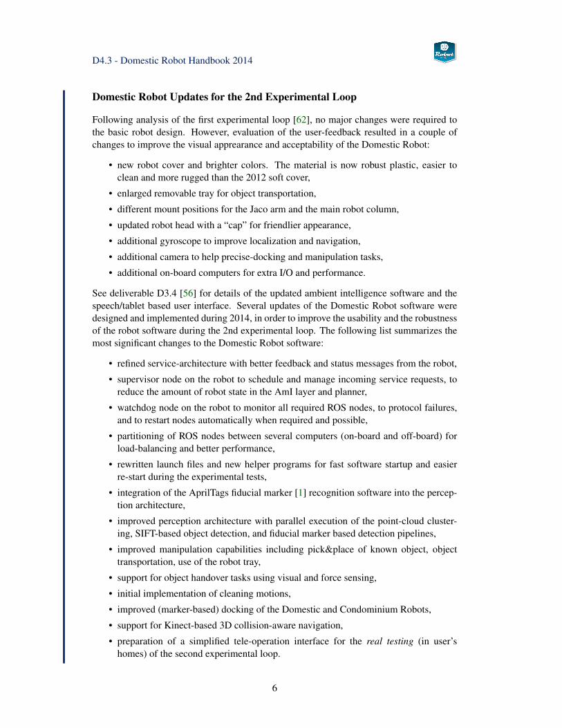
Domestic Robot Updates for the 2nd Experimental Loop
Following analysis of the first experimental loop [62], no major changes were required tothe basic robot design. However, evaluation of the user-feedback resulted in a couple ofchanges to improve the visual apprearance and acceptability of the Domestic Robot:
• new robot cover and brighter colors. The material is now robust plastic, easier toclean and more rugged than the 2012 soft cover,
• enlarged removable tray for object transportation,
• different mount positions for the Jaco arm and the main robot column,
• updated robot head with a “cap” for friendlier appearance,
• additional gyroscope to improve localization and navigation,
• additional camera to help precise-docking and manipulation tasks,
• additional on-board computers for extra I/O and performance.
See deliverable D3.4 [56] for details of the updated ambient intelligence software and thespeech/tablet based user interface. Several updates of the Domestic Robot software weredesigned and implemented during 2014, in order to improve the usability and the robustnessof the robot software during the 2nd experimental loop. The following list summarizes themost significant changes to the Domestic Robot software:
• refined service-architecture with better feedback and status messages from the robot,
• supervisor node on the robot to schedule and manage incoming service requests, toreduce the amount of robot state in the AmI layer and planner,
• watchdog node on the robot to monitor all required ROS nodes, to protocol failures,and to restart nodes automatically when required and possible,
• partitioning of ROS nodes between several computers (on-board and off-board) forload-balancing and better performance,
• rewritten launch files and new helper programs for fast software startup and easierre-start during the experimental tests,
• integration of the AprilTags fiducial marker [1] recognition software into the percep-tion architecture,
• improved perception architecture with parallel execution of the point-cloud cluster-ing, SIFT-based object detection, and fiducial marker based detection pipelines,
• improved manipulation capabilities including pick&place of known object, objecttransportation, use of the robot tray,
• support for object handover tasks using visual and force sensing,
• initial implementation of cleaning motions,
• improved (marker-based) docking of the Domestic and Condominium Robots,
• support for Kinect-based 3D collision-aware navigation,
• preparation of a simplified tele-operation interface for the real testing (in user’shomes) of the second experimental loop.
6
D4.3 - Domestic Robot Handbook 2014
2 Hardware
This chapter documents the hardware components of the domestic robot. See Fig. 1 onpage 4 for a photo of the completed robot. Please refer to project report D4.1 [57] and twoconference papers [7, 10] for additional details and the explanation of the design processincluding the selection of the sensors and the Jaco manipulator.
2.1 Concept and General Robot Design
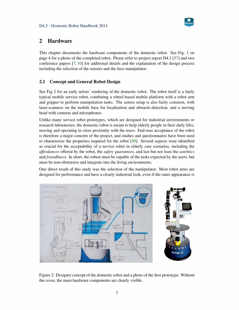
See Fig 2 for an early artists’ rendering of the domestic robot. The robot itself is a fairlytypical mobile service robot, combining a wheel-based mobile platform with a robot armand gripper to perform manipulation tasks. The sensor setup is also fairly common, withlaser-scanners on the mobile base for localization and obstacle-detection, and a movinghead with cameras and microphones.
Unlike many service robot prototypes, which are designed for industrial environments orresearch laboratories, the domestic robot is meant to help elderly people in their daily lifes,moving and operating in close proximity with the users. End-user acceptance of the robotis therefore a major concern of the project, and studies and questionnaires have been usedto characterize the properties required for the robot [49]. Several aspects were identifiedas crucial for the acceptability of a service robot in elderly care scenarios, including theaffordances offered by the robot, the safety guarantees, and last but not least the astehticsand friendliness. In short, the robust must be capable of the tasks expected by the users, butmust be non-obstrusive and integrate into the living environments.
One direct result of this study was the selection of the manipulator. Most robot arms aredesigned for performance and have a clearly industrial look, even if the outer appearance is
Figure 2: Designer concept of the domestic robot and a photo of the first prototype. Withoutthe cover, the main hardware components are clearly visible.
7
D4.3 - Domestic Robot Handbook 2014
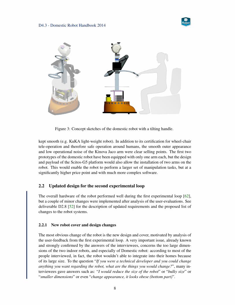
Figure 3: Concept sketches of the domestic robot with a tilting handle.
kept smooth (e.g. KuKA light-weight robot). In addition to its certification for wheel-chairtele-operation and therefore safe operation around humans, the smooth outer appearanceand low operational noise of the Kinova Jaco arm were clear selling points. The first twoprototypes of the domestic robot have been equipped with only one arm each, but the designand payload of the Scitos-G5 platform would also allow the installation of two arms on therobot. This would enable the robot to perform a larger set of manipulation tasks, but at asignificantly higher price point and with much more complex software.
2.2 Updated design for the second experimental loop
The overall hardware of the robot performed well during the first experimental loop [62],but a couple of minor changes were implemented after analysis of the user-evaluations. Seedeliverable D2.8 [52] for the description of updated requirements and the proposed list ofchanges to the robot systems.
2.2.1 New robot cover and design changes
The most obvious change of the robot is the new design and cover, motivated by analysis ofthe user-feedback from the first experimental loop. A very important issue, already knownand strongly confirmed by the answers of the interviewees, concerns the too large dimen-sions of the two indoor robots, and especially of Domestic robot: according to most of thepeople interviewed, in fact, the robot wouldn’t able to integrate into their homes becauseof its large size. To the question “If you were a technical developer and you could changeanything you want regarding the robot, what are the things you would change?”, many in-terviewees gave answers such as: “I would reduce the size of the robot” or “bulky size” or“smaller dimensions” or even “change appearance, it looks obese (bottom part)”.
8
D4.3 - Domestic Robot Handbook 2014
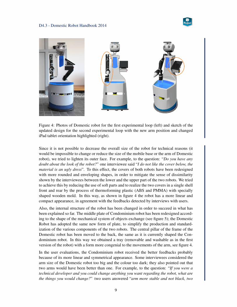
Figure 4: Photos of Domestic robot for the first experimental loop (left) and sketch of theupdated design for the second experimental loop with the new arm position and changediPad tablet orientation highlighted (right).
Since it is not possible to decrease the overall size of the robot for technical reasons (itwould be impossible to change or reduce the size of the mobile base or the arm of Domesticrobot), we tried to lighten its outer face. For example, to the question: “Do you have anydoubt about the look of the robot?” one interviewee said “I do not like the cover below, thematerial is an ugly dress”. To this effect, the covers of both robots have been redesignedwith more rounded and enveloping shapes, in order to mitigate the sense of dissimilarityshown by the interviewees between the lower and the upper part of the two robots. We triedto achieve this by reducing the use of soft parts and to realize the two covers in a single shellfront and rear by the process of thermoforming plastic (ABS and PMMA) with speciallyshaped wooden mold. In this way, as shown in figure 4 the robot has a more linear andcompact appearance, in agreement with the feedbacks detected by interviews with users.
Also, the internal structure of the robot has been changed in order to succeed in what hasbeen explained so far. The middle plate of Condominium robot has been redesigned accord-ing to the shape of the mechanical system of objects exchange (see figure 5); the DomesticRobot has adopted the same new form of plate, to simplify the production and standard-ization of the various components of the two robots. The central pillar of the frame of theDomestic robot has been moved to the back, the same as it is currently shaped the Con-dominium robot. In this way we obtained a tray (removable and washable as in the firstversion of the robot) with a form more congenial to the movements of the arm, see figure 4.
In the user evaluations, the Condominium robot received the better feedbacks probablybecause of its more linear and symmetrical appearance. Some interviewees considered thearm size of the Domestic robot too big and the colour too dark; they also pointed out thattwo arms would have been better than one. For example, to the question: “If you were atechnical developer and you could change anything you want regarding the robot, what arethe things you would change?” two users answered “arm more stable and not black, two
9
D4.3 - Domestic Robot Handbook 2014
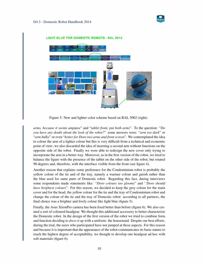
Figure 5: New and lighter color scheme based on RAL 5002 (right).
arms, because it seems amputee” and “tablet front, put both arms”. To the question: “Doyou have any doubt about the look of the robot?” some answers were: “arm too dark” or“arm bulky” or even “better for Doro two arms and front screen”. We contemplated the ideato colour the arm of a lighter colour but this is very difficult from a technical and economicpoint of view; we also discarded the idea of inserting a second arm without functions on theopposite side of the robot. Finally we were able to redesign the new cover only trying toincorporate the arm in a better way. Moreover, as in the first version of the robot, we tried tobalance the figure with the presence of the tablet on the other side of the robot, but rotated90 degrees and, therefore, with the interface visible from the front (see figure 4).
Another reason that explains some preference for the Condominium robot is probably theyellow colour of the tie and of the tray, namely a warmer colour and garish rather thanthe blue used for same parts of Domestic robot. Regarding this fact, during interviewssome respondents made statements like: “Doro colours too gloomy” and ‘´Doro shouldhave brightest colours”. For this reason, we decided to keep the grey colour for the maincover and for the head, the yellow colour for the tie and the tray of Condominium robot andchange the colour of the tie and the tray of Domestic robot: according to all partners, thefinal choice was a brighter and lively colour like light blue (figure 5).
Finally, the Asus XtionPro camera has been fixed better than before (figure 6). We also cre-ated a sort of coloured headgear. We thought this additional accessory to better characterizethe Domestic robot. In the design of the first version of the robot we tried to combine formand function deciding to dress it up with a uniform: the housemaid. Despite our best efforts,during the trial, the users who participated have not jumped at these aspects. For this reasonand because it is important that the appearance of the robot communicates its basic nature toreach the highest degree of acceptability, we thought to develop one headgear ad hoc withsoft materials (figure 6).
10
D4.3 - Domestic Robot Handbook 2014
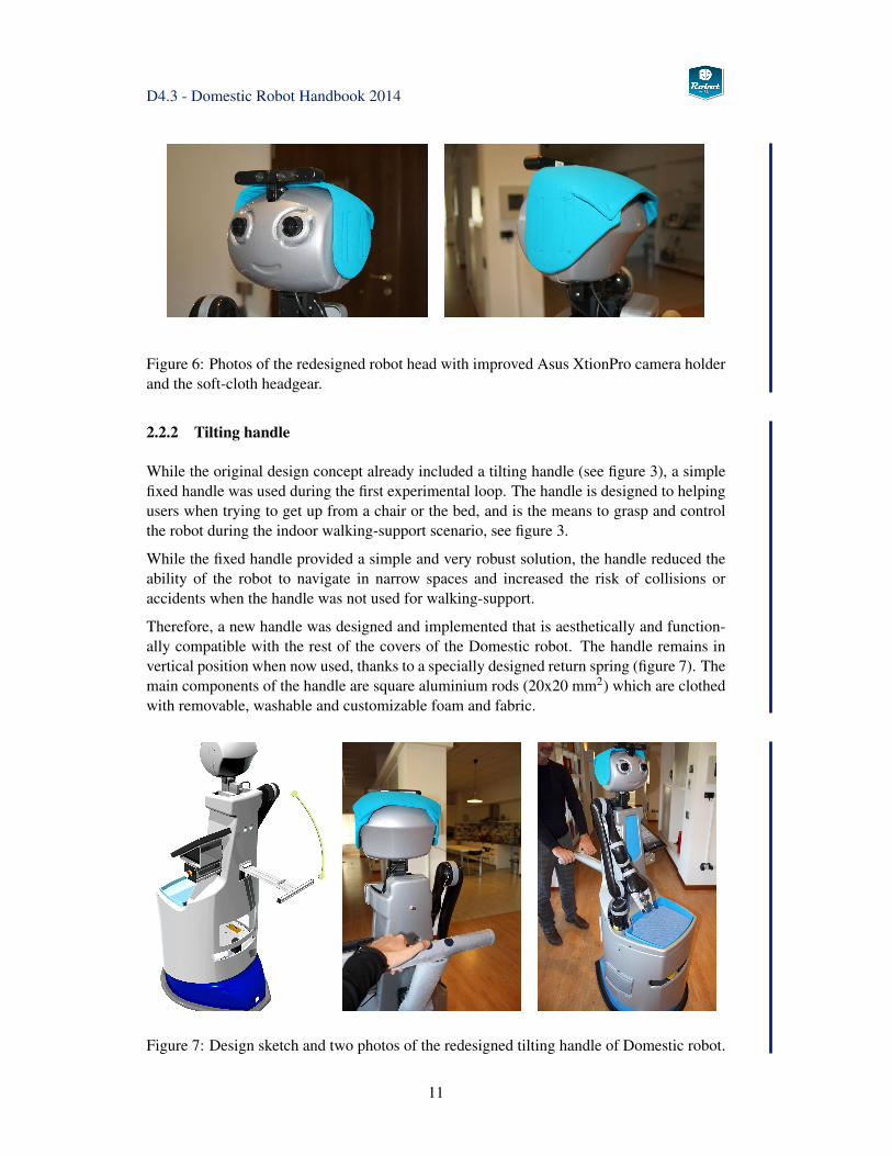
Figure 6: Photos of the redesigned robot head with improved Asus XtionPro camera holderand the soft-cloth headgear.
2.2.2 Tilting handle
While the original design concept already included a tilting handle (see figure 3), a simplefixed handle was used during the first experimental loop. The handle is designed to helpingusers when trying to get up from a chair or the bed, and is the means to grasp and controlthe robot during the indoor walking-support scenario, see figure 3.
While the fixed handle provided a simple and very robust solution, the handle reduced theability of the robot to navigate in narrow spaces and increased the risk of collisions oraccidents when the handle was not used for walking-support.
Therefore, a new handle was designed and implemented that is aesthetically and function-ally compatible with the rest of the covers of the Domestic robot. The handle remains invertical position when now used, thanks to a specially designed return spring (figure 7). Themain components of the handle are square aluminium rods (20x20 mm2) which are clothedwith removable, washable and customizable foam and fabric.
Figure 7: Design sketch and two photos of the redesigned tilting handle of Domestic robot.
11
D4.3 - Domestic Robot Handbook 2014
Fully autonomous operation of the robot is not planned for the walking-support scenario.Instead, switches or strain-gauges are installed on the handle, allowing the user to drive therobot around. The sensors for moving the robot by the user are nserted within the foam.Pushing the buttons, the user can drive the robot forward, left and right. During driving,the robot software checks the laser-scans from the robot sensors and automatically stops therobot to avoid collisions.
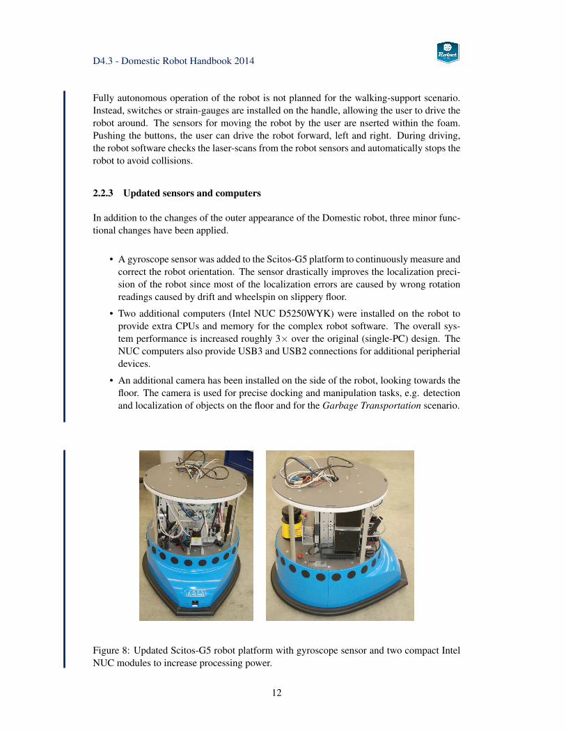
2.2.3 Updated sensors and computers
In addition to the changes of the outer appearance of the Domestic robot, three minor func-tional changes have been applied.
• A gyroscope sensor was added to the Scitos-G5 platform to continuously measure andcorrect the robot orientation. The sensor drastically improves the localization preci-sion of the robot since most of the localization errors are caused by wrong rotationreadings caused by drift and wheelspin on slippery floor.
• Two additional computers (Intel NUC D5250WYK) were installed on the robot toprovide extra CPUs and memory for the complex robot software. The overall sys-tem performance is increased roughly 3× over the original (single-PC) design. TheNUC computers also provide USB3 and USB2 connections for additional peripherialdevices.
• An additional camera has been installed on the side of the robot, looking towards thefloor. The camera is used for precise docking and manipulation tasks, e.g. detectionand localization of objects on the floor and for the Garbage Transportation scenario.
Figure 8: Updated Scitos-G5 robot platform with gyroscope sensor and two compact IntelNUC modules to increase processing power.
12
D4.3 - Domestic Robot Handbook 2014
2.3 SCITOS G5 platform
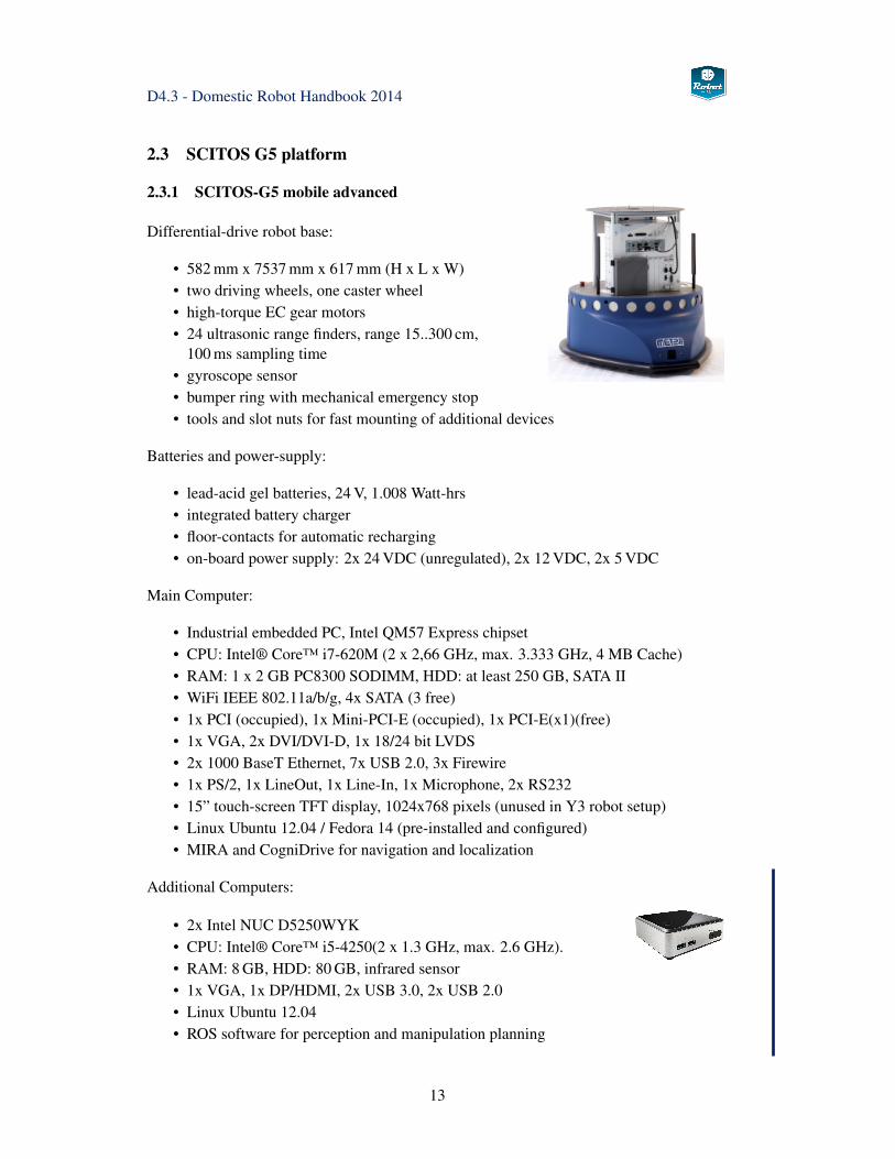
2.3.1 SCITOS-G5 mobile advanced
Differential-drive robot base:
• 582 mm x 7537 mm x 617 mm (H x L x W)• two driving wheels, one caster wheel• high-torque EC gear motors• 24 ultrasonic range finders, range 15..300 cm,
100 ms sampling time• gyroscope sensor• bumper ring with mechanical emergency stop• tools and slot nuts for fast mounting of additional devices
Batteries and power-supply:
• lead-acid gel batteries, 24 V, 1.008 Watt-hrs• integrated battery charger• floor-contacts for automatic recharging• on-board power supply: 2x 24 VDC (unregulated), 2x 12 VDC, 2x 5 VDC
Main Computer:
• Industrial embedded PC, Intel QM57 Express chipset• CPU: Intel® Core™ i7-620M (2 x 2,66 GHz, max. 3.333 GHz, 4 MB Cache)• RAM: 1 x 2 GB PC8300 SODIMM, HDD: at least 250 GB, SATA II• WiFi IEEE 802.11a/b/g, 4x SATA (3 free)• 1x PCI (occupied), 1x Mini-PCI-E (occupied), 1x PCI-E(x1)(free)• 1x VGA, 2x DVI/DVI-D, 1x 18/24 bit LVDS• 2x 1000 BaseT Ethernet, 7x USB 2.0, 3x Firewire• 1x PS/2, 1x LineOut, 1x Line-In, 1x Microphone, 2x RS232• 15” touch-screen TFT display, 1024x768 pixels (unused in Y3 robot setup)• Linux Ubuntu 12.04 / Fedora 14 (pre-installed and configured)• MIRA and CogniDrive for navigation and localization
Additional Computers:
• 2x Intel NUC D5250WYK• CPU: Intel® Core™ i5-4250(2 x 1.3 GHz, max. 2.6 GHz).• RAM: 8 GB, HDD: 80 GB, infrared sensor• 1x VGA, 1x DP/HDMI, 2x USB 3.0, 2x USB 2.0• Linux Ubuntu 12.04• ROS software for perception and manipulation planning
13
D4.3 - Domestic Robot Handbook 2014
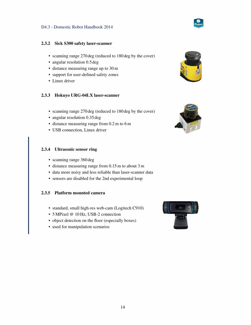
2.3.2 Sick S300 safety laser-scanner
• scanning range 270deg (reduced to 180deg by the cover)• angular resolution 0.5deg• distance measuring range up to 30 m• support for user-defined safety zones• Linux driver
2.3.3 Hokuyo URG-04LX laser-scanner
• scanning range 270deg (reduced to 180deg by the cover)• angular resolution 0.35deg• distance measuring range from 0.2 m to 6 m• USB connection, Linux driver
2.3.4 Ultrasonic sensor ring
• scanning range 360deg• distance measuring range from 0.15 m to about 3 m• data more noisy and less reliable than laser-scanner data• sensors are disabled for the 2nd experimental loop
2.3.5 Platform mounted camera
• standard, small high-res web-cam (Logitech C910)• 5 MPixel @ 10 Hz, USB-2 connection• object detection on the floor (especially boxes)• used for manipulation scenarios
14
D4.3 - Domestic Robot Handbook 2014
2.4 Kinova Jaco manipulator
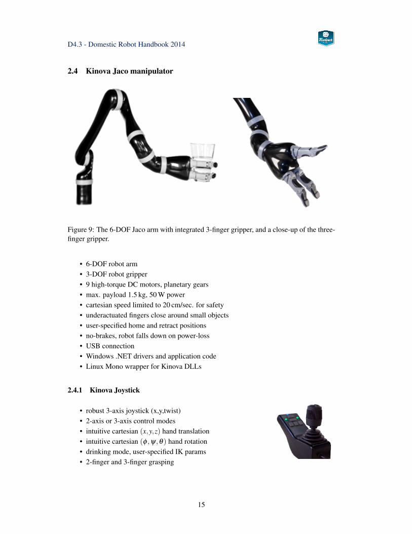
Figure 9: The 6-DOF Jaco arm with integrated 3-finger gripper, and a close-up of the three-finger gripper.
• 6-DOF robot arm• 3-DOF robot gripper• 9 high-torque DC motors, planetary gears• max. payload 1.5 kg, 50 W power• cartesian speed limited to 20 cm/sec. for safety• underactuated fingers close around small objects• user-specified home and retract positions• no-brakes, robot falls down on power-loss• USB connection• Windows .NET drivers and application code• Linux Mono wrapper for Kinova DLLs
2.4.1 Kinova Joystick
• robust 3-axis joystick (x,y,twist)• 2-axis or 3-axis control modes• intuitive cartesian (x,y,z) hand translation• intuitive cartesian (φ ,ψ,θ) hand rotation• drinking mode, user-specified IK params• 2-finger and 3-finger grasping
15
D4.3 - Domestic Robot Handbook 2014
2.5 Sensor head
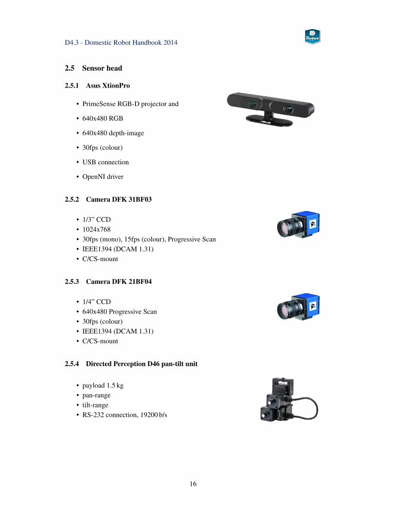
2.5.1 Asus XtionPro
• PrimeSense RGB-D projector and
• 640x480 RGB
• 640x480 depth-image
• 30fps (colour)
• USB connection
• OpenNI driver
2.5.2 Camera DFK 31BF03
• 1/3” CCD• 1024x768• 30fps (mono), 15fps (colour), Progressive Scan• IEEE1394 (DCAM 1.31)• C/CS-mount
2.5.3 Camera DFK 21BF04
• 1/4” CCD• 640x480 Progressive Scan• 30fps (colour)• IEEE1394 (DCAM 1.31)• C/CS-mount
2.5.4 Directed Perception D46 pan-tilt unit
• payload 1.5 kg• pan-range• tilt-range• RS-232 connection, 19200 b/s
16
D4.3 - Domestic Robot Handbook 2014
2.6 Human-Robot interface
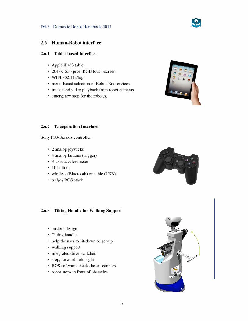
2.6.1 Tablet-based Interface
• Apple iPad3 tablet• 2048x1536 pixel RGB touch-screen• WIFI 802.11a/b/g• menu-based selection of Robot-Era services• image and video playback from robot cameras• emergency stop for the robot(s)
2.6.2 Teleoperation Interface
Sony PS3-Sixaxis controller
• 2 analog joysticks• 4 analog buttons (trigger)• 3-axis accelerometer• 10 buttons• wireless (Bluetooth) or cable (USB)• ps3joy ROS stack
2.6.3 Tilting Handle for Walking Support
• custom design• Tilting handle• help the user to sit-down or get-up• walking support• integrated drive switches• stop, forward, left, right• ROS software checks laser-scanners• robot stops in front of obstacles
17
D4.3 - Domestic Robot Handbook 2014
2.7 Safety Features
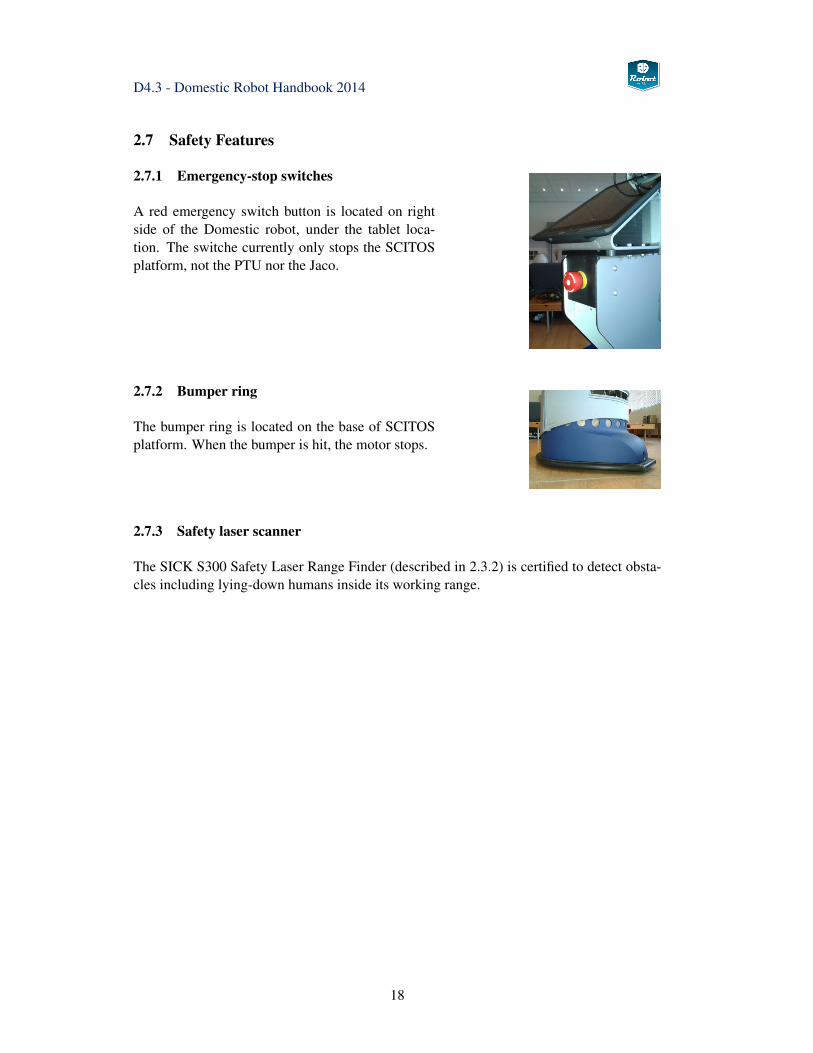
2.7.1 Emergency-stop switches
A red emergency switch button is located on rightside of the Domestic robot, under the tablet loca-tion. The switche currently only stops the SCITOSplatform, not the PTU nor the Jaco.
2.7.2 Bumper ring
The bumper ring is located on the base of SCITOSplatform. When the bumper is hit, the motor stops.
2.7.3 Safety laser scanner
The SICK S300 Safety Laser Range Finder (described in 2.3.2) is certified to detect obsta-cles including lying-down humans inside its working range.
18
D4.3 - Domestic Robot Handbook 2014
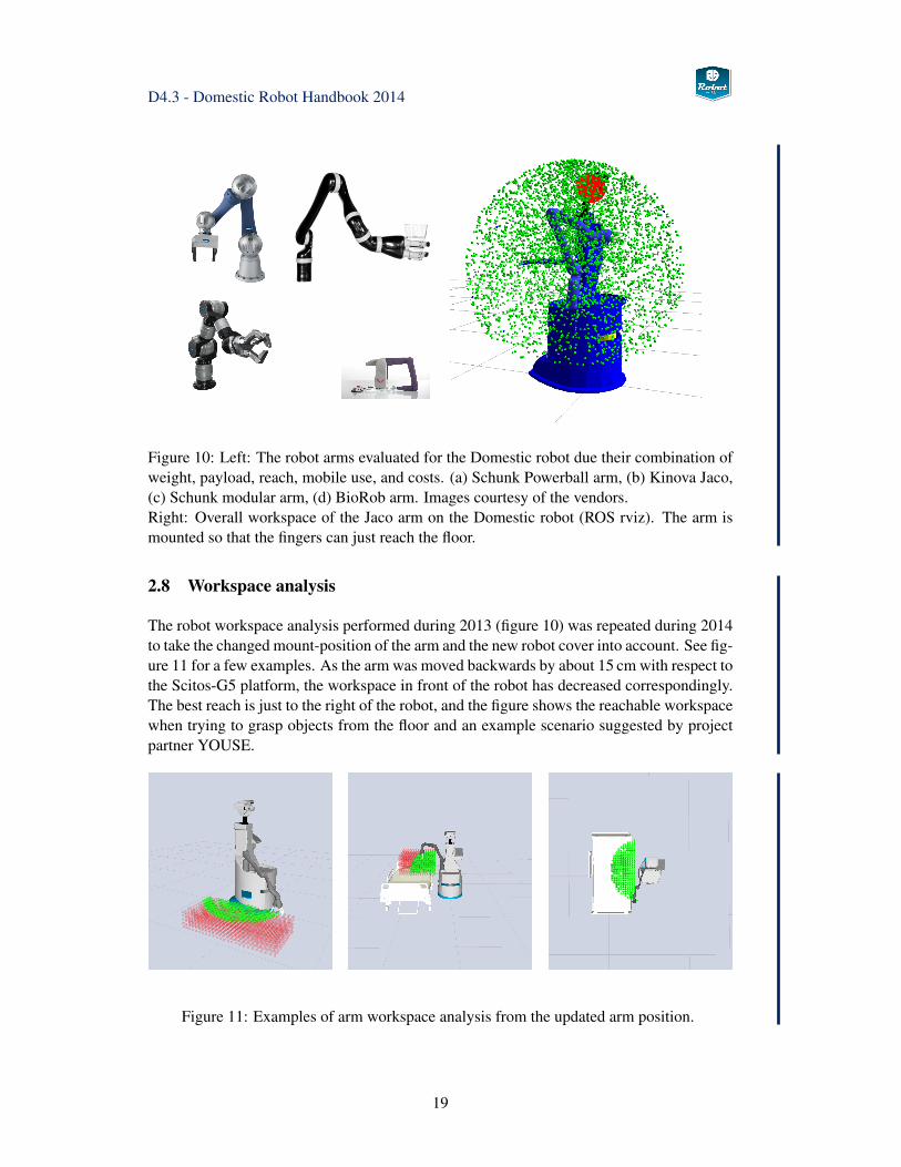
Figure 10: Left: The robot arms evaluated for the Domestic robot due their combination ofweight, payload, reach, mobile use, and costs. (a) Schunk Powerball arm, (b) Kinova Jaco,(c) Schunk modular arm, (d) BioRob arm. Images courtesy of the vendors.Right: Overall workspace of the Jaco arm on the Domestic robot (ROS rviz). The arm ismounted so that the fingers can just reach the floor.
2.8 Workspace analysis
The robot workspace analysis performed during 2013 (figure 10) was repeated during 2014to take the changed mount-position of the arm and the new robot cover into account. See fig-ure 11 for a few examples. As the arm was moved backwards by about 15 cm with respect tothe Scitos-G5 platform, the workspace in front of the robot has decreased correspondingly.The best reach is just to the right of the robot, and the figure shows the reachable workspacewhen trying to grasp objects from the floor and an example scenario suggested by projectpartner YOUSE.
Figure 11: Examples of arm workspace analysis from the updated arm position.
19

D4.3 - Domestic Robot Handbook 2014
20
D4.3 - Domestic Robot Handbook 2014
3 Software
This chapter summarizes the overall software architecture for the domestic robot and pro-vides tutorial information about all key software components. For detailed informationincluding the complete API and implementation notes, please refer to the Robot-Era wikiand the SVN repository. See chapter 5 for detailed instruction on how to download, install,and set-up the major components of the domestic robot software.
First, section 3.1 presents an overview of the software architecture, which is built around theROS robot operating system [35] framework and communication model. A short introduc-tion of the major aspects of ROS is given in section 3.1.1 while section 3.1.2 summarizesthe URDF robot model created for the domestic robot.
Next, section 3.2 explains the main software components for localization and navigation ofthe mobile robot, which uses a combination of ROS and the MIRA/Cognidrive software.A MIRA-ROS bridge developed within the project creates the seamless interface betweenCognidrive and ROS.
Section 3.3 describes the sensing and perception architecture, including the low-level in-terfaces to the cameras and the XtionPro RGB-D camera, camera calibration, and imageprocessing and the planned object-recognition and object pose tracking modules.
Section 3.4 sketches the overall concept for object manipulation and the core software mod-ules available within the ROS framework. The Kinova Jaco robot arm is then presented insection 3.5, including a short description of the hardware, the original Windows-based soft-ware, and the details of the current ROS interface for the Jaco arm. For more advancedmanipulation tasks, collision- and context-aware motion planning is required. An overviewof the Domestic robot manipulation action server and the MoveIt! framework is sketched insections 3.7 and 3.6. The next section 3.10 describes the simulation model of the domesticrobot created for the Gazebo [24] simulator.
Last but not least, section 3.11 explains the interface layer between the PEIS ambient in-telligence network and the domestic robot software. The interface is based on dedicatedexekutor ROS nodes (previously known as tuplehandler) that register themselves with thePEIS network, listening for incoming commands and parameters and providing feedbackand execution monitoring.
3.1 Overview
As explained in the previous project report Domestic Robot Specification [57], the overallsoftware consists of three major modules, with the PEIS ecology managing the whole multi-robot system and sensor network. The ROS framework was chosen as the core of the robotcontrol while MIRA/Cognidrive is used for 2D-navigation and localization. See Fig. 12 fora block diagram that highlights the main components of the software.
21
D4.3 - Domestic Robot Handbook 2014
DetectObjectService
CleanTableService BringObjectService
MoveToService
MIRA−ROS
object−
handover
Jacoscanners
laser− Kinect CamerasSCITOS
CameraImageService
GraspObjectService
developers
plannerPEISend users
HRI
. . .
2
1
3
4
. . .
HW
(navigation_stack)
PCL OMPLOpenCV
doro−GUI
messages
environment_perception
object_perception
roscpp
MoveIt!
MIRA / CogniDrive
MIRA−
Center
rviz
. . .
ROS
roscore
rospy
Orocos
OpenNI gstreamer Kinova.DLL
services supervisor and sequencer
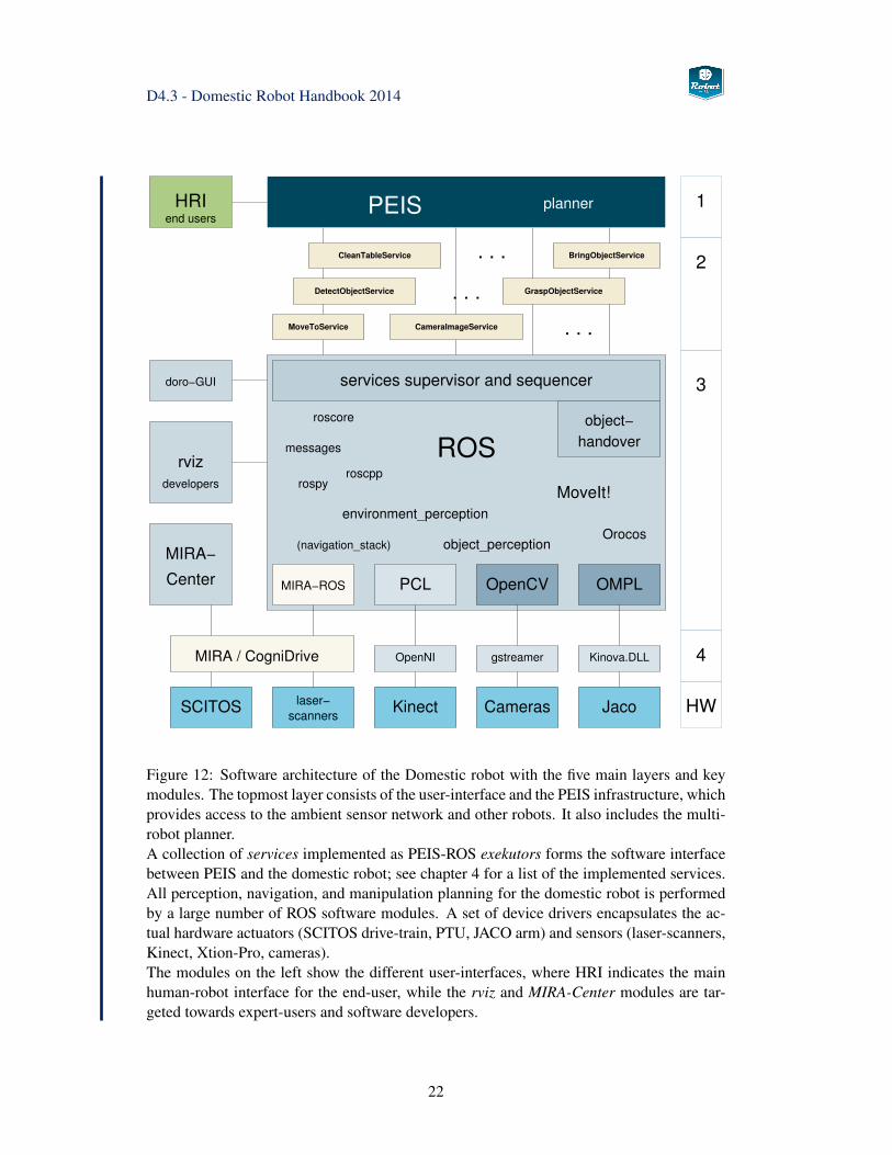
Figure 12: Software architecture of the Domestic robot with the five main layers and keymodules. The topmost layer consists of the user-interface and the PEIS infrastructure, whichprovides access to the ambient sensor network and other robots. It also includes the multi-robot planner.A collection of services implemented as PEIS-ROS exekutors forms the software interfacebetween PEIS and the domestic robot; see chapter 4 for a list of the implemented services.All perception, navigation, and manipulation planning for the domestic robot is performedby a large number of ROS software modules. A set of device drivers encapsulates the ac-tual hardware actuators (SCITOS drive-train, PTU, JACO arm) and sensors (laser-scanners,Kinect, Xtion-Pro, cameras).The modules on the left show the different user-interfaces, where HRI indicates the mainhuman-robot interface for the end-user, while the rviz and MIRA-Center modules are tar-geted towards expert-users and software developers.
22
D4.3 - Domestic Robot Handbook 2014
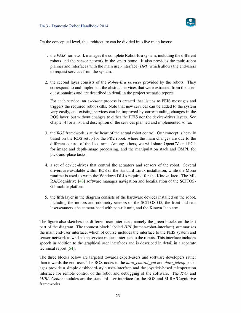
On the conceptual level, the architecture can be divided into five main layers:
1. the PEIS framework manages the complete Robot-Era system, including the differentrobots and the sensor network in the smart home. It also provides the multi-robotplanner and interfaces with the main user-interface (HRI) which allows the end-usersto request services from the system.
2. the second layer consists of the Robot-Era services provided by the robots. Theycorrespond to and implement the abstract services that were extracted from the user-questionnaires and are described in detail in the project scenario reports.
For each service, an exekutor process is created that listens to PEIS messages andtriggers the required robot skills. Note that new services can be added to the systemvery easily, and existing services can be improved by corresponding changes in theROS layer, but without changes to either the PEIS nor the device-driver layers. Seechapter 4 for a list and description of the services planned and implemented so far.
3. the ROS framework is at the heart of the actual robot control. Our concept is heavilybased on the ROS setup for the PR2 robot, where the main changes are due to thedifferent control of the Jaco arm. Among others, we will share OpenCV and PCLfor image and depth-image processing, and the manipulation stack and OMPL forpick-and-place tasks.
4. a set of device-drives that control the actuators and sensors of the robot. Severaldrivers are available within ROS or the standard Linux installation, while the Monoruntime is used to wrap the Windows DLLs required for the Kinova Jaco. The MI-RA/Cognidrive [43] software manages navigation and localiziation of the SCITOS-G5 mobile platform.
5. the fifth layer in the diagram consists of the hardware devices installed on the robot,including the motors and odometry sensors on the SCITOS-G5, the front and rearlaserscanners, the camera-head with pan-tilt unit, and the Kinova Jaco arm.
The figure also sketches the different user-interfaces, namely the green blocks on the leftpart of the diagram. The topmost block labeled HRI (human-robot-interface) summarizesthe main end-user interface, which of course includes the interface to the PEIS system andsensor-network as well as the service-request interface to the robots. This interface includesspeech in addition to the graphical user interfaces and is described in detail in a separatetechnical report [54].
The three blocks below are targeted towards expert-users and software developers ratherthan towards the end-user. The ROS nodes in the doro_control_gui and doro_teleop pack-ages provide a simple dashboard-style user-interface and the joystick-based teleoperationinterface for remote control of the robot and debugging of the software. The RViz andMIRA-Center modules are the standard user-interface for the ROS and MIRA/Cognidriveframeworks.
23
D4.3 - Domestic Robot Handbook 2014
3.1.1 ROS
Within just five years since its introduction, the ROS framework or robot operating systemhas established itself as one of the favorite middleware solutions for robot integration [35].Due to the flexibility of the software and the liberal open-source licensing, ROS has alsobeen selected by several vendors of robot hardware and sensors for their own products. Visitthe ROS website at www.ros.org for an overview and the ROS Wiki at www.ros.org/wiki forthe list of currently supported software, documentation, and tutorials. By now, literally hun-dreds of software modules are available, ranging from low-level device-drivers via sensordata processing up to software for symbolic planning and human-robot interaction. Thisincludes several key software libraries, for example, the OpenCV computer vision library,the PCL point-cloud processing library, and the OpenRAVE and OMPL motion-planningframeworks.
Regarding the context of Robot-Era, ROS has been chosen as the core control frameworkfor several leading service robots, notably the PR2 from WillowGarage and the Care-o-botseries designed by Fraunhofer. Additionally, the so-called MoveIt manipulation platformintegrates a large set of open-source software for constraints- and collision-aware motion-planning and grasping, with optional backends supporting tactile-sensor based grasping. Fordetails, see section 3.6 below. This provides a unique base for the complex manipulationtasks targeted by the Robot-Era services. As UHAM owns one PR2 robot and has long usedROS for several other projects, the selection of ROS as the main control framework for thedomestic robot was an easy choice.
Despite the catchy name, ROS is not an operating system itself, but rather creates an easy-to-use communication middleware on top of existing operating systems. However, ROSprovides a set of tools to manage large software projects, including a file-system struc-ture consisting of stacks and packages, a build-system capabable of tracking and resolvingsoftware dependencies. The software can be built and installed on several operating sys-tems, with Ubuntu Linux as the main developer platform, but other variants of Linux aresupported as well. There is also (partial) support on Microsoft Windows and on top of An-droid. However, due to the large number of software packages and dependencies, buildingthe framework on the less well supported platforms is a huge task, and for now only UbuntuLinux (12.04 LTS) can be used for the domestic robot.
ROS nodes The central paradigm underlying ROS software development is a system oflargely independent but interacting software processes, called ROS nodes. That is, thereis no centralized single control level or monotlithic master process. Instead, ROS nodescan be added to a system at any time, allowing for the easy integration of new hardwarecomponents and software modules.
Unlike some other frameworks, ROS is mostly language-neutral, and bindings are providedfor C/C++, Python, LISP. Additional language bindings are available as third-party soft-ware, including the RosJava interface.
Roscore and parameter server In a typical ROS system, there are only two centralizedprocesses, namely the ROS core process and the parameter server. The roscore process actsare the central registry for all software nodes, either on the local system or distributed over alocal network. It provides a lookup-service that allows other nodes to query the existing list
24
D4.3 - Domestic Robot Handbook 2014
of processes and to establish point-to-point communication between nodes. The parameterserver is used as the central repository of node parameters; it supports different namespacesand provides an easy means to store and retrieve software parameters without having tochange (and recompile) code.
ROS topics and services There are two basic paradigms for communication betweenROS nodes, namely topics and services. The so-called ROS topics provide a unidirec-tional communication channel between one or many publishers and an arbitrary number ofsubscribers. A newly created ROS node advertises all topics it wants to publish with theroscore loookup service. Clients that want to subscribe to a topic first query the roscore,than negotiate a point-to-point communication with the corresponding publisher.
The base ROS system already defines a large set of standard messages, but one of the realstrengths of ROS is the ability to define a hierarchy of user-defined messages on top ofthe available messages. The ROS build infrastructure automatically resolves the dependen-cies and creates the header/class files required for easy access to message contents fromwithin the ROS nodes. For example, to specify the 6D-pose of an object, the geome-try_msgs/PoseStamped message is used, which consists of a std_msgs/Header and a ge-ometry_msgs/Pose. The header in turn is built up from a uint32 sequence number, a timetimestamp, and a string for the name of the coordinate frame (if any). The Pose consistof one Point with three float64 (x,y,z) coordinates and one Quaternion with four float64(x,y,z,w) values. This mechanism is very powerful and significantly reduces the effort todefine structured data-exchange between different nodes.
The second communication mechanism in ROS are the so-called services, which imple-ment the request-response paradigm for communication between clients and a single server.Again, the messages to be exchanged between the client and the server are defined usingthe hierarchical ROS message format. Once a request has been sent, the client must waituntil the server responds, without any control of timeouts. This is also a frequent sourceof deadlocks, as clients may wait indefinitely for a service not yet started or crashed. Thenewer actionlib infrastructure provides a way around this problem, as an actionlib-servicegoal request can be canceled by the client at any time. Also, the server can provide a pe-riodic feedback to indiciate progress to the client before the original service goal has beenreached.
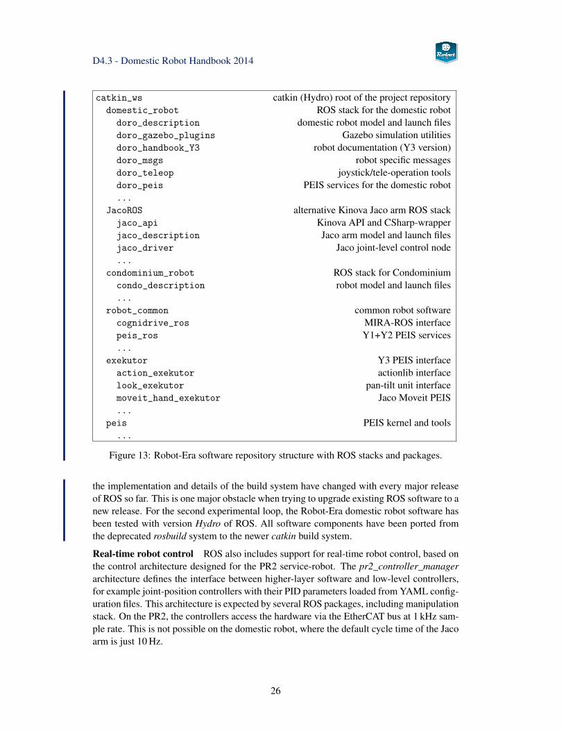
Stacks and packages Apart from the core runtime functionality, ROS also suggests aspecific file-sytem structure for its components, organized into stacks and packages. Thisis backed up with a set of command-line tools for navigation and a complex build infras-tructure that automatically traverses the inter-package dependencies declared in the mani-fest.xml files and recompiles missing or outdated packages and messages. The overall setupof the Robot-Era ROS software is shown in Fig. 13. There are several stacks, with onestack for the domestic and the condominium robot each, while the common perception andnavigation functions are collected in the robot_common stack.
Build system To manage the compilation of hundreds of software packages, ROS pro-vides its own build system, with the catkin and rosmake tools. When configured accord-ingly, rosmake can detect, download, and install missing system dependencies automaticallywith help from the rosinstall tools. The search path for the different stacks and packages isconfigured using the all-important ROS_PACKAGE_PATH environment variable. However,
25
D4.3 - Domestic Robot Handbook 2014
catkin_ws catkin (Hydro) root of the project repositorydomestic_robot ROS stack for the domestic robot
doro_description domestic robot model and launch filesdoro_gazebo_plugins Gazebo simulation utilitiesdoro_handbook_Y3 robot documentation (Y3 version)doro_msgs robot specific messagesdoro_teleop joystick/tele-operation toolsdoro_peis PEIS services for the domestic robot...
JacoROS alternative Kinova Jaco arm ROS stackjaco_api Kinova API and CSharp-wrapperjaco_description Jaco arm model and launch filesjaco_driver Jaco joint-level control node...
condominium_robot ROS stack for Condominiumcondo_description robot model and launch files...
robot_common common robot softwarecognidrive_ros MIRA-ROS interfacepeis_ros Y1+Y2 PEIS services...
exekutor Y3 PEIS interfaceaction_exekutor actionlib interfacelook_exekutor pan-tilt unit interfacemoveit_hand_exekutor Jaco Moveit PEIS...
peis PEIS kernel and tools...
Figure 13: Robot-Era software repository structure with ROS stacks and packages.
the implementation and details of the build system have changed with every major releaseof ROS so far. This is one major obstacle when trying to upgrade existing ROS software to anew release. For the second experimental loop, the Robot-Era domestic robot software hasbeen tested with version Hydro of ROS. All software components have been ported fromthe deprecated rosbuild system to the newer catkin build system.
Real-time robot control ROS also includes support for real-time robot control, based onthe control architecture designed for the PR2 service-robot. The pr2_controller_managerarchitecture defines the interface between higher-layer software and low-level controllers,for example joint-position controllers with their PID parameters loaded from YAML config-uration files. This architecture is expected by several ROS packages, including manipulationstack. On the PR2, the controllers access the hardware via the EtherCAT bus at 1 kHz sam-ple rate. This is not possible on the domestic robot, where the default cycle time of the Jacoarm is just 10 Hz.
26
D4.3 - Domestic Robot Handbook 2014
Domestic robot
Scitos G5 platform
left wheelright wheelcaster wheel
Sick S300 Hokuyo URG24x Sonar
Kinova Jaco arm
joints 1...6
finger 1..3
Camera head
DP PTU-46
Xtion-pro
Camera
/base_odom
/cmd_vel
/base_scan
/sonar_XY
/base_scan_rear
/joint_states
/joint_states
/ptu/pan|tilt
/kinect_*
/camera_*
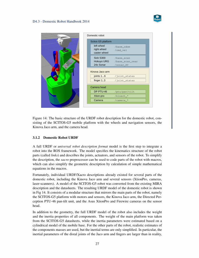
Figure 14: The basic structure of the URDF robot description for the domestic robot, con-sisting of the SCITOS-G5 mobile platform with the wheels and navigation sensors, theKinova Jaco arm, and the camera head.
3.1.2 Domestic Robot URDF
A full URDF or universal robot description format model is the first step to integrate arobot into the ROS framework. The model specifies the kinematics structure of the robotparts (called links) and describes the joints, actuators, and sensors of the robot. To simplifythe description, the xacro preprocessor can be used to code parts of the robot with macros,which can also simplify the geometric description by calculation of simple mathematicalequations in the macros.
Fortunately, individual URDF/Xacro descriptions already existed for several parts of thedomestic robot, including the Kinova Jaco arm and several sensors (XtionPro, cameras,laser-scanners). A model of the SCITOS-G5 robot was converted from the existing MIRAdescription and the datasheets. The resulting URDF model of the domestic robot is shownin Fig 14. It consists of a modular structure that mirrors the main parts of the robot, namelythe SCITOS-G5 platform with motors and sensors, the Kinova Jaco arm, the Directed Per-ception PTU-46 pan-tilt unit, and the Asus XtionPro and Firewire cameras on the sensorhead.
In addition to the geometry, the full URDF model of the robot also includes the weightand the inertia properties of all components. The weight of the main platform was takenfrom the SCITOS-G5 datasheets, while the inertia parameters were estimated based on acylindrical model of the mobile base. For the other parts of the robot, realistic estimates ofthe components masses are used, but the inertial terms are only simplified. In particular, theinertial parameters of the distal joints of the Jaco arm and fingers are larger than in reality,
27
D4.3 - Domestic Robot Handbook 2014
which does no harm on the real robot but helps to keep the simulation model stable.
Regarding the sensor setup of the robot, the existing models of the Sick S-300 and HokuyoURG-04LX laser-scanners provided by ROS were used, with the mounting position on themobile base taken from the SCITOS-G5 datasheet. For use in simulation, the ray geometryand deadband settings were adapted to the current mounting positions as well. The sonarsensors are also included, with the sensor model backported from the Gazebo ray_sensorplugin. The sensor model should be accurate enough for single sensors, but does not modelthe inevitable crosstalk when running a ring of 24 sonar sensors at the same time. ROS alsoincludes the URDF models for the Asus XtionPro depth-camera and the standard camerasmounted on the sensor-head of the domestic robot.
So far, the default parameters are used for the intrinsic calibration of the cameras in theURDF model; actual calibration data for the cameras is stored in external files as requiredby the ROS camera drivers (openni2, gstreamer).
3.1.3 Coordinate-systems and tf
All geometry calculations in ROS are based on a right-handed coordinate system. For thedomestic robot, the base coordinate system was chosen according to the usual convention,with the x-direction towards the front, y to the left, and z upwards. The actual origin is at thefloor (z = 0) and halfways between the two driving wheels. While this coordinate systemis difficult to measure from the outside, the choice of origin is typical for differential-driverobots and simplifies the 2D-navigation calculations.
Managed by the ROS tf transformation library, a separate coordinate system is attachedto every part (link) of the robot as defined in the robot URDF model. See Fig. 15 for ascreenshot of the robot in the rviz visualization tool, with the tf coordinate-system markersenabled and overlayed on the semi-transparent robot model. For each marker, the red, green,and blue arrows correspond to the x,y,z directions respectively.
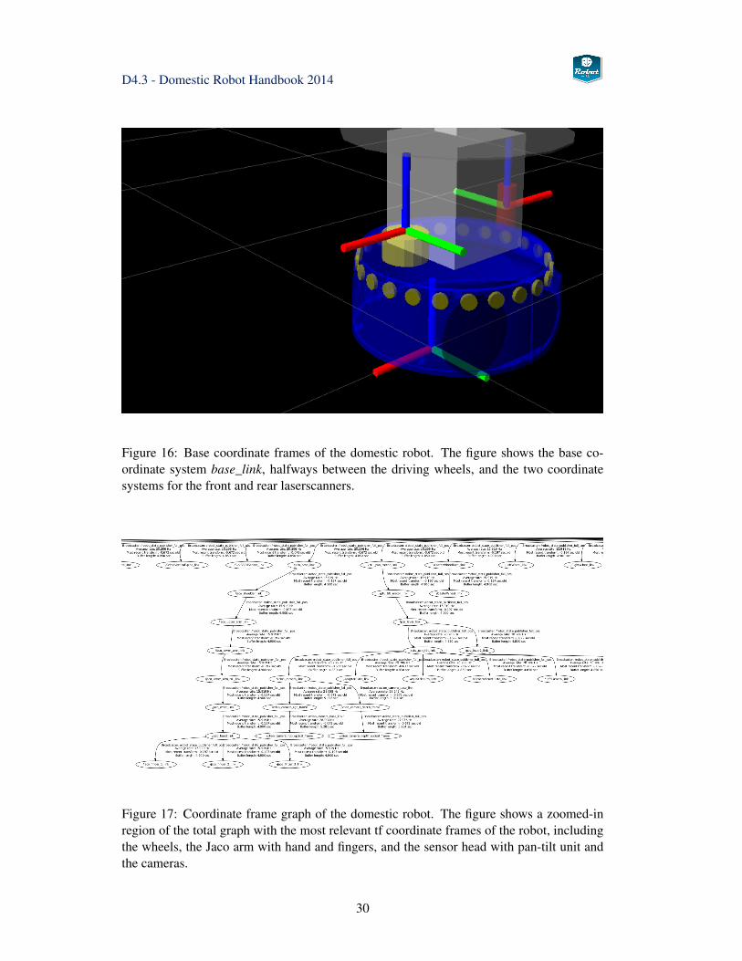
See Fig. 17 for a cut-out of the whole coordinate frame graph showing the most relevantcoordinate systems, including the wheels, Jaco arm with hand and fingers, and the sensorhead. The tf graph can be visualized at runtime using the tf view_frames command,
rosrun tf view_frames
which generates a snapshot of the tf graph, and saves the result in a file called frames.pdf.
28
D4.3 - Domestic Robot Handbook 2014
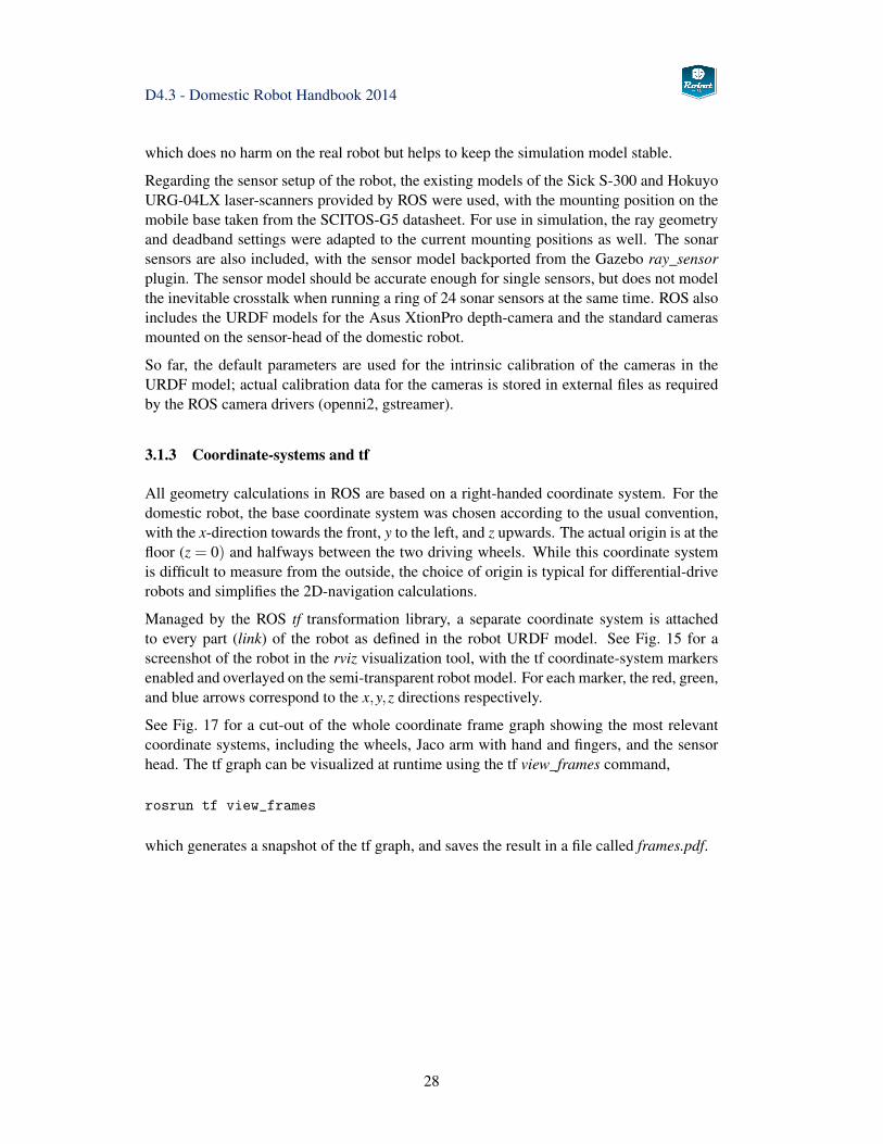
Figure 15: Coordinate frames of the domestic robot. The figure shows the rviz visualizationof all tf coordinate frames used in the domestic robot URDF model (red: x, green: y, blue:z). The main coordinate system of the platform has positive x towards the front, y to theleft, and z upwards. In the default orientation, the pan-tilt angles are both 0, and the x-axesof the Kinect/Xtion and the cameras point forward.Also note the coordinate systems for the segments of the Jaco arm in the current mountposition. As shown, the jaco_shoulder_yaw_joint is at−π/2 radians. Moving the shoulder-yaw joint of the arm to its zero position results in a self-collision with the central pillar of therobot, and must be avoided. The ring of coordinate system indicators around the platformbase corresponds to the sonar sensors.
29
D4.3 - Domestic Robot Handbook 2014
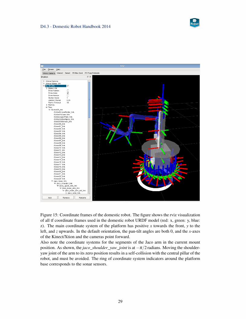
Figure 16: Base coordinate frames of the domestic robot. The figure shows the base co-ordinate system base_link, halfways between the driving wheels, and the two coordinatesystems for the front and rear laserscanners.
Figure 17: Coordinate frame graph of the domestic robot. The figure shows a zoomed-inregion of the total graph with the most relevant tf coordinate frames of the robot, includingthe wheels, the Jaco arm with hand and fingers, and the sensor head with pan-tilt unit andthe cameras.
30
D4.3 - Domestic Robot Handbook 2014
3.1.4 Launching the domestic robot
To simplify operation of the domestic robot, the startup of the different required devicedrivers and ROS nodes is managed by a set of ROS launch files. At the moment, the startupfiles do not include all required nodes. It is recommended to run the launch files and pro-grams in different terminals for easier control and debugging:
shell-1> roslaunch doro_description domestic_bringup.launchshell-2> rosrun rviz rvizshell-3> roslaunch doro_moveit_config move_group.launchshell-4> roslaunch visionhub start_perception.launchshell-5> roslaunch doro_peis domestic_services.launch
Domestic robot bringup The first step required for robot startup is running the domes-tic_bringup.launch launch file. This file starts the different essential low-level processesthat are needed for robot operation. Therefore, this launch file is required, while the otherlaunch files are optional and may be skipped. For example, manipulation is not available onthe condominium robot, but the platform navigation and other Robot-Era services can bestarted exactly as on the domestic robot.
In the current version, the bringup launch file integrates the following functions:
• uploads the domestic robot URDF to the robot_description parameter onto the pa-rameter server.
• starts the MIRA software for control of the SCITOS platform, powering up the dif-ferent sensors and the pan-tilt-unit, and enabling the front and rear laser-scanners.
• starts the cognidrive_ros bridge to interface the MIRA localization and navigationfunctions.
• starts the jaco_node for joint-level control of the Kinova Jaco arm and hand.
• starts the doro_ptu46 node for controlling the pan-tilt unit.
• runs the cameras.launch file which in turn starts the ROS nodes for the XtionProRGB-D camera and the firewire cameras.
• starts a set of utility nodes. This includes the doro_joint_state_merger node and therobot_state_publisher required for providing the tf transformation library with up-to-date robot joint-state data.
• starts the joy nodes for ROS tele-operation.
• starts the mjpeg_server webserver that allows clients to access the camera-images asan MJPEG-format stream from any web-browser.
The Jaco arm should be powered-on and in its retract position (see section 3.5 on page 63for details) before running the launch script. If initialization of the Jaco arm fails, or ifthe Jaco node needs to be restarted, it is possible to restart the arm using the providedjaco_node.launch file:
31
D4.3 - Domestic Robot Handbook 2014
rosnode kill jaco_noderoslaunch doro_description jaco_node.launch
Do not launch the original Kinova jaco_node/jaco_node.launch file, which loads a wrongrobot configuration.
Depending on the system- and MIRA-configuration, several devices (e.g. laser-scanners,PTU) may only be powered-up when MIRA is started, and it takes some time until thedevices have completed their own initialization sequence. In particular, the PTU node isknown to crash sometimes, when the PTU initialization is triggered and takes too long. Youcan restart the PTU node easily,
rosnode kill pturoslaunch doro_ptu46 doro_ptu.launch
but this will not restart the PTU calibration sequence. If necessary, power-cycle the PTUusing the small power-switch on the PTU controller, to ensure that the PTU is in its zeroposition before restarting the PTU node.
To visualize the current ROS node graph, including the interconnections via ROS topics(but not services), run the rxgraph utility,
rxgraph -o rxgraph.dotdot -T png -o output.png rxgraph.dotdot -T pdf -o output.pdf rxgraph.dot
ROS nodes started during bringup The following list documents the key ROS nodesstarted as part of the above launch sequence,
rosnode list/cognidrive_ros/diag_agg/doro_joint_state_merger/doro_telnet_server/jaco_node/left_camera/right_camera/floor_camera/mjpeg_server/ptu/ptu_action_server/robot_state_publisher_full_pos/rosout/rossink_1365097477302051982/xtion_camera/depth/metric_rect/xtion_camera/depth/points
32
D4.3 - Domestic Robot Handbook 2014
/xtion_camera/depth/rectify_depth/xtion_camera/depth_registered/metric_rect/xtion_camera/disparity_depth_registered/xtion_camera/driver/xtion_camera/ir/rectify_ir/xtion_camera/points_xyzrgb_depth_rgb/xtion_camera/register_depth_rgb/xtion_camera/rgb/debayer/xtion_camera/rgb/rectify_color/xtion_camera/rgb/rectify_mono/xtion_camera_nodelet_manager
where the /cognidrive_ros node provides the platform control and navigation, while/jaco_node controls the arm, and /ptu controls the PTU. The laser-scanner data andlocalization is published by /cognidrive_ros, while /leftcamera, /rightcamera,/floorcamera and /xtion_camera/* are the controller nodes for the RGB- and XtionProRGB-D cameras.
ROS topics published after bringup Once the basic robot bringup-sequence has beencompleted, almost 100 ROS topics are active on the domestic robot. The following listdocuments the key ROS topics published as part of the robot-bringup launch sequence,sorted alphabetically,
rostopic list
/base_odometry/odom/base_scan/base_scan_rear/battery/server2/cmd_abs_finger/cmd_abs_joint/cmd_rel_cart/cmd_vel/diagnostics/diagnostics_agg/doro/scitos/wheel_states/hand_goal/hand_pose/initialpose/jaco/joint_states/jaco_finger_1_joint_controller/command/jaco_finger_2_joint_controller/command/jaco_finger_3_joint_controller/command/jaco_joint_trajectory_action_controller/joint_trajectory_action/goal/jaco_kinematic_chain_controller/follow_joint_trajectory/cancel
33
D4.3 - Domestic Robot Handbook 2014
/jaco_node/cur_goal/joint_states/left_camera/camera_info/left_camera/image_raw/left_camera/.../right_camera/.../floor_camera/....../map/map_metadata/move_base/cancel/move_base/feedback/move_base/goal/move_base/result/move_base/status/move_base_simple/goal
/ptu/ResetPtu/goal/ptu/SetPTUState/goal/ptu/cmd/ptu/joint_states/rosout/rosout_agg/tf/xtion_camera/depth/camera_info/xtion_camera/depth/disparity/xtion_camera/depth/image/xtion_camera/depth/image/compressed.../xtion_camera/depth/image_rect_raw/xtion_camera/depth/points/xtion_camera/depth/rectify_depth/parameter_descriptions/xtion_camera/depth/rectify_depth/parameter_updates/xtion_camera/depth_registered/camera_info/xtion_camera/depth_registered/disparity/xtion_camera/depth_registered/image/xtion_camera/depth_registered/image_rect/compressed/xtion_camera/depth_registered/points.../xtion_camera/driver/parameter_descriptions/xtion_camera/driver/parameter_updates/xtion_camera/ir/camera_info/xtion_camera/ir/image_rect/compressed/xtion_camera/rgb/image_color/compressed...
34
D4.3 - Domestic Robot Handbook 2014
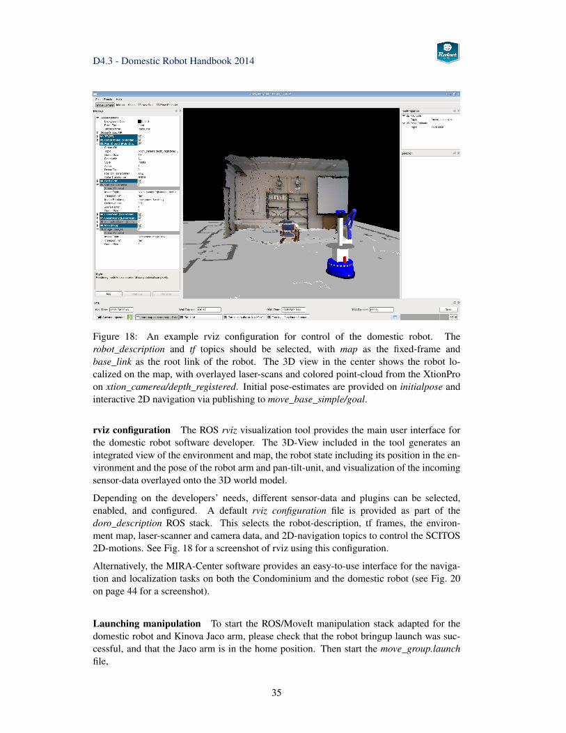
Figure 18: An example rviz configuration for control of the domestic robot. Therobot_description and tf topics should be selected, with map as the fixed-frame andbase_link as the root link of the robot. The 3D view in the center shows the robot lo-calized on the map, with overlayed laser-scans and colored point-cloud from the XtionProon xtion_camerea/depth_registered. Initial pose-estimates are provided on initialpose andinteractive 2D navigation via publishing to move_base_simple/goal.
rviz configuration The ROS rviz visualization tool provides the main user interface forthe domestic robot software developer. The 3D-View included in the tool generates anintegrated view of the environment and map, the robot state including its position in the en-vironment and the pose of the robot arm and pan-tilt-unit, and visualization of the incomingsensor-data overlayed onto the 3D world model.
Depending on the developers’ needs, different sensor-data and plugins can be selected,enabled, and configured. A default rviz configuration file is provided as part of thedoro_description ROS stack. This selects the robot-description, tf frames, the environ-ment map, laser-scanner and camera data, and 2D-navigation topics to control the SCITOS2D-motions. See Fig. 18 for a screenshot of rviz using this configuration.
Alternatively, the MIRA-Center software provides an easy-to-use interface for the naviga-tion and localization tasks on both the Condominium and the domestic robot (see Fig. 20on page 44 for a screenshot).
Launching manipulation To start the ROS/MoveIt manipulation stack adapted for thedomestic robot and Kinova Jaco arm, please check that the robot bringup launch was suc-cessful, and that the Jaco arm is in the home position. Then start the move_group.launchfile,
35
D4.3 - Domestic Robot Handbook 2014
roslaunch doro_moveit_config move_group.launch
and wait until all nodes and services have been started (The Arm in RViz matches the actualposition and OMPL is displayed as the planning library).
See section 3.6 below for an overview of the ROS manipulation implementation and adetailed description of the different ROS nodes and services that provide the robot withcollision-aware motion planning.
Launching Robot-Era services See chapter 4 for an overview of the Robot-Era servicearchitecture and a list of the services. To connect the robot to the PEIS ambient intelligencenetwork, including the multi-robot planner and human-robot interface, just launch the do-mestic_services.launch file. This assumes that the robot bringup and manipulation launchfiles have been started and all services are running,
roslaunch doro_peis domestic_services.launch
3.1.5 Running ROS on Multiple Computers
In many cases, the raw compute power provided by a single computer will not be sufficientto run advanced algorithms with many nodes. Fortunately, ROS provides a very simple andconvenient way to distribute computation across multiple machines, because nodes runningon different computers can communicate seamlessly using ROS messages and services.The key idea is to start the roscore lookup-service process on one selected machine, whichthen acts as the master and provides the node, topic, and service lookup for all machinesin the network. The master returns the hostnames and ports used for communication onthe requested topics and services, and the nodes establish the direct network connection toexchange data between them. Typically, either the on-board computer of the mobile robotor a fast machine is acting as the ROS master. Note that there is also ongoing work onmulti-master ROS systems, but this is beyond the scope of the handbook.
In some cases, the communication with the roscore process is possible, while actual data-transfer between nodes on different computers is not working. A typical situation is thatrostopic list returns the full list of topics managed by the roscore process, while runningrostopic echo on one of the listed topics does not return any data. This occurs when thehostname lookup on the different machines in the network is not working properly. How-ever, ROS requires the mutual hostname lookup to work in order to exchange data betweendifferent machines. The easiest solution is to check the /etc/hosts files and to explicitly addthe names of all required computers:
cat /etc/hosts127.0.0.1 localhost192.168.0.33 scitos scitos.informatik.uni-hamburg.de192.168.0.44 laptop...
36
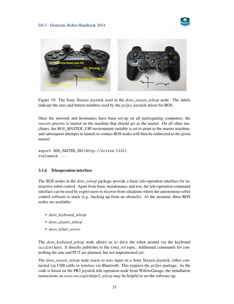
D4.3 - Domestic Robot Handbook 2014
9: Wrist and Fingers
8: Shoulder and Elbow
10: Driving
11: Camera-head pan-tilt
Figure 19: The Sony Sixaxis joystick used in the doro_sixaxis_teleop node. The labelsindicate the axes and button numbers used by the ps3joy joystick driver for ROS.
Once the network and hostnames have been set-up on all participating computers, theroscore process is started on the machine that should act as the master. On all other ma-chines, the ROS_MASTER_URI environment variable is set to point to the master machine,and subsequent attempts to launch or contact ROS nodes will then be redirected to the givenmaster:
export ROS_MASTER_URI=http://scitos:11311roslaunch ...
3.1.6 Teleoperation interface
The ROS nodes in the doro_teleop package provide a basic tele-operation interface for in-teractive robot control. Apart from basic maintenance and test, the tele-operation commandinterface can be used by expert users to recover from situations where the autonomous robotcontrol software is stuck (e.g. backing up from an obstacle). As the moment, three ROSnodes are available:
• doro_keyboard_teleop
• doro_sixaxis_teleop
• doro_telnet_server
The doro_keyboard_teleop node allows us to drive the robot around via the keyboard(a,s,d,w) keys. It directly publishes to the /cmd_vel topic. Additional commands for con-trolling the arm and PUT are planned, but not implemented yet.
The doro_sixaxis_teleop node reacts to user input on a Sony Sixaxis joystick, either con-nected via USB cable or wireless via Bluetooth. This requires the ps3joy package. As thecode is based on the PR2 joystick tele-operation node from WillowGarage, the installationinstructions on www.ros.org/wiki/pr2_teleop may be helpful to set the software up.
37
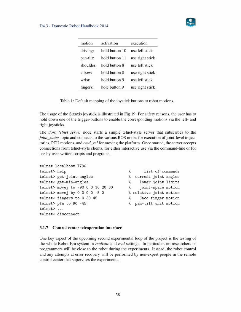
D4.3 - Domestic Robot Handbook 2014
motion activation execution
driving: hold button 10 use left stick
pan-tilt: hold button 11 use right stick
shoulder: hold button 8 use left stick
elbow: hold button 8 use right stick
wrist: hold button 9 use left stick
fingers: hole button 9 use right stick
Table 1: Default mapping of the joystick buttons to robot motions.
The usage of the Sixaxis joystick is illustrated in Fig 19. For safety reasons, the user has tohold down one of the trigger-buttons to enable the corresponding motions via the left- andright joysticks.
The doro_telnet_server node starts a simple telnet-style server that subscribes to thejoint_states topic and connects to the various ROS nodes for execution of joint-level trajec-tories, PTU motions, and cmd_vel for moving the platform. Once started, the server acceptsconnections from telnet-style clients, for either interactive use via the command-line or foruse by user-written scripts and programs.
telnet localhost 7790telnet> help % list of commandstelnet> get-joint-angles % current joint anglestelnet> get-min-angles % lower joint limitstelnet> movej to -90 0 0 10 20 30 % joint-space motiontelnet> movej by 0 0 0 0 -5 0 % relative joint motiontelnet> fingers to 0 30 45 % Jaco finger motiontelnet> ptu to 90 -45 % pan-tilt unit motiontelnet> ...telnet> disconnect
3.1.7 Control center teleoperation interface
One key aspect of the upcoming second experimental loop of the project is the testing ofthe whole Robot-Era system in realistic and real settings. In particular, no researchers orprogrammers will be close to the robot during the experiments. Instead, the robot controland any attempts at error recovery will be performed by non-expert people in the remotecontrol center that supervises the experiments.
38
D4.3 - Domestic Robot Handbook 2014
3.1.8 Robot calibration
No calibration is required for the SCITOS base platform. The location of the driving wheelsis fixed and the gear-ratios of the differential drive are known. Any errors in wheel odometry(e.g. due to wheel slip) are handled by the AMCL localization when fusing the laser-scannerand odometry data in MIRA. The front and rear laser-scanners and the sonar sensors aremounted fixed onto the platform, and their positions are documented in the SCITOS robotdescriptions (MIRA XML and ROS URDF). However, any systematic modeling errors arehard to check, because Metralabs does not define reference points on the platform. Notethat the curved outer shape of the SCITOS platform makes it rather difficult to estimate thebase_link and mount positions of the sensors precisely.
For the Jaco arm, no calibration tools are provided by Kinova, and the factory calibrationis assumed to be correct. Automatic full-robot calibration by matching camera images toarm movements is possible, but has not yet been implemented on the domestic robot. Also,there is no accuracy data available for the Jaco arm from the vendor. While the human userautomatically compensates small errors when tele-operating the arm, any such errors maycompromise the manipulation capabilites under autonomous control. Experience gainedthroughout the project experimental phases will show whether any additional modeling isrequired.
Regarding the base position of the arm, the documentation from Kinova seems to be inaccu-rate, but corrected positions are used in the robot URDF model. Note that the base positionused in the URDF should be checked carefully against the actual mount point of the arm.A set of calibration jigs might be useful to verify arm poses, but so far neither Kinova norMetralabs do provide any such objects.
The pan-tilt unit is driven by stepper-motors and performs an automatic self-calibrationsequence when powered up. Afterwards, position is tracked by counting motor steps, whichis highly accurate. Note that the PTU ROS node should be started when the PTU is in itszero position.
Camera calibration, file formats, calibration file locations, etc., see section 3.3 below.
39
D4.3 - Domestic Robot Handbook 2014
3.2 Robot localization and navigation
This section summarizes the localization, collision-avoidance, and navigation algorithmsimplemented on the domestic robot. The robot acts in a known indoor environment withlevel floors, which greatly simplifies the problem because well-known 2D localization andpath-planning methods and a static map of the environment can be used. See [37] for areview of the relevant basic algorithms.
As explained in the earlier project report D4.1 Domestic robot platform specification [57],the MIRA framework with the CogniDrive module will be used for the control and sensor-interface of the SCITOS-G5 mobile platform, while a simple MIRA-ROS bridge interfacesto the ROS framework. This architecture was decided on after careful evaluation of the ROSnavigation_stack, which basically provides the same functionality as the pair of MIRA andCognidrive. However, using ROS here instead of MIRA would require us to rewrite thelow-level drivers to the SCITOS platform with little other benefit.
See Fig. 12 on page 22 for the main software blocks of the domestic robot. The compo-nents concerned with navigation are located in the lower-left corner of the diagram, namelythe MIRA framework with the hardware drivers for the SCITOS-G5 motors and odome-try sensors, and the interfaces to the Sick and Hokuyo laserscanners. Robust localization,collision-avoidance and path-planning is performed by the CogniDrive software, and theMIRA-Center user-interface allows the expert user to control the robot motions. The nav-igation combines a static map of the environment with a dynamic occupancy grid mapgenerated from the laser-scanner data.
The material in the next two sections of this chapter is a shorted summary of the MIRA de-scription already provided in [57] (chapter 4). It is repeated here to make this handbook self-contained and to motivate the design of the MIRA-ROS bridge explained in section 3.2.3.
3.2.1 MIRA
The MIRA framework is a robot middleware that targets a modular software developmentprocess built around a set of communicating processes or modules. See the webpageat www.mira-project.org/MIRA-doc-devel/index.html for documentation. The overall ap-proach and goals are therefore similar to ROS, but several design decisions have resulted ina rather different implementation. For communication, the MIRA framework offers mes-sage passing by implementing the publisher/subscriber pattern as well as Remote ProcedureCalls (RPC). Beside this communication, the MIRA base and framework provide muchmore functionality, including visualization of the data flow and the data passed betweenmodules, error monitoring and tracking and identifying problems with the modular applica-tion.
MIRA provides a middleware that handles the communication between the modules, orrespectively the units, and ties these units together to compose a complex application. TheMIRA core is divided into the following software components:
• base: commonly used classes, algorithms, and helpers.
• framework: publisher/subscriber communication.
40
D4.3 - Domestic Robot Handbook 2014
• GUI: classes, widgets and tools for visualization, Rich Client Platform for modularGUI design.
• packages: collection of components, dependency information.
• toolboxes: algorithms and classes used by other components.
• domains: one or more units to be used by other components.
Similar to ROS, the MIRA system supports the robot developer on several levels.
• component level: managing executables and shared libraries, with dependency infor-mation encoded in manifest files.
• computation graph level: managing units communicating via typed and named chan-nels, support for remote procedure calls (RPC).
• runtime level: executables and share libraries.
• filesystem level: package, toolboxes, and domains.
• repository level: support for SVN and FTP repositories, source- and binary-codedistribution, and software packages.
MIRA is designed to allow for fast and easy creation and testing of new distributed softwaremodules. The interface is very lightweight and fully transparent and it hides implementationdetails like data-locking, usage of threads and cyclic processes, and the location of sendersand receivers within the same process, a different process, or a remote process.
A detailed comparison between MIRA and ROS was included in the previous project re-port D4.1 [57], where MIRA was shown to have significant advantages in several importantareas. On the other hand, ROS has a larger user-community and many more software pack-ages are available for ROS.
3.2.2 Cognidrive
The CogniDrive software from Metralabs has been selected for the navigation and local-ization capabilities of both the domestic and condominium robots. See chapter 5 of theprevious report D4.1 [57] for a detailed description of the CogniDrive software.
Instead of providing only the standard drive-to command, the motion-planning in Cogni-Drive is based on a set of objectives, which enable a fine-grained control over the robotmotion. Several objectives can be active at the same time, with different weight factorsadjustable from the high-level (application or user) interface.
Motion requests are scheduled as tasks which can be subdivided into several sub-tasks,each of which is then guided by the active objectives. Additionally, CogniDrive explicitlyprovides one of the key functions required by the Robot-Era services, namely the capabilityto navigate in a multi-map environment, e.g. several floors in a building that are connectedby an elevator.
41
D4.3 - Domestic Robot Handbook 2014
CogniDrive supports a variety of different requirements such as:
• support for non-holonomic robots of different sizes
• navigation with high precision (e.g. Docking, handling of narrow passages)
• fast path planning and online dynamic replanning
• taking moving obstacles into account
• consideration of traffic rules (e.g. forbidden areas and speed limits)
For task processing, the motion planner and the objectives play a major role. Each objectiveis a separate software module specialized for certain tasks like following a person, drivingat a certain speed or direction, etc. The objectives are realized as software plugins. Thisallows us to add new objectives easily when new tasks are necessary without changing otherparts of the navigator. The output of the objectives is then used by the motion planner togenerate motion commands that are then sent to the robot’s motor controllers. Some objec-tives require additional information from other navigational modules such as localizationand mapping algorithms or modules for user interaction like person trackers.
Each sub-task can be parametrized by numerous tasks specific options, including: goal pointto drive to, map to drive to preferred driving direction of the robot (backward, forward orboth), accuracy for reaching a goal point, accuracy for the orientation angle at a goal point,maximum allowed driving distance (e.g. during exploration). By specifying a combina-tion of sub-tasks and their parameters the robot’s navigational behaviour can be completelymodified at runtime. For example the complex task "Drive backward to the destination (10,0) in map ‘Floor2’ with an accuracy of ±0.5 m and turn to the orientation of 70° with anaccuracy of ±15°" is easily handled by CogniDrive.
Internally, CogniDrive manages a grid map of the environment, where cell covers a certainarea of the velocity space and corresponds to a certain velocity command. For motionplanning in CogniDrive, a cost function is computed for each cell and therefore the velocitycommand that yields the smallest cost is chosen. In the original Dynamic Window Approach[33] that cost function is composed of three different functions, called objectives. Oneobjective yields large costs when the robot would get too close to obstacles by choosingthat certain action. The second objective prefers actions that lead to high speeds and thethird one takes care of the robot’s orientation. Additionally, each objective can forbid acertain action completely by marking it as "not admissible" when a certain requirement,like the minimal distance to an obstacle, is not met. If at least one objective marks an actionas "not admissible", the action is excluded from the set of allowed actions.
After all active objective were processed for all cells in the dynamic window and the costs ofall cells were computed based on the weighted sum, from all admissible cells, the cell withthe lowest cost value is chosen and the corresponding action is sent to the motor controllersin terms of a velocity command. Afterwards, the whole processing cycle is repeated untilthe current task and the specified goal is reached. Several different objectives are supported:
• distance objective: responsible for avoiding collisions by calculating the distancebetween the robot and obstacles along the predicted trajectory. The objective alsotakes the braking distance of the robot into account.
42
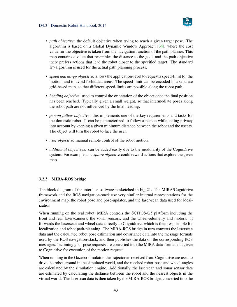
D4.3 - Domestic Robot Handbook 2014
• path objective: the default objective when trying to reach a given target pose. Thealgorithm is based on a Global Dynamic Window Approach [34], where the costvalue for the objective is taken from the navigation function of the path planner. Thismap contains a value that resembles the distance to the goal, and the path objectivethere prefers actions that lead the robot closer to the specified target. The standardE*-algorithm is used for the actual path planning process.
• speed and no-go objective: allows the application-level to request a speed-limit for themotion, and to avoid forbidded areas. The speed-limit can be encoded in a separategrid-based map, so that different speed-limits are possible along the robot path.
• heading objective: used to control the orientation of the object once the final positionhas been reached. Typically given a small weight, so that intermediate poses alongthe robot path are not influenced by the final heading.
• person follow objective: this implements one of the key requirements and tasks forthe domestic robot. It can be parameterized to follow a person while taking privacyinto account by keeping a given minimum distance between the robot and the useers.The object will turn the robot to face the user.
• user objective: manual remote control of the robot motion.
• additional objectives: can be added easily due to the modularity of the CogniDrivesystem. For example, an explore objective could reward actions that explore the givenmap.
3.2.3 MIRA-ROS bridge
The block diagram of the interface software is sketched in Fig 21. The MIRA/Cognidriveframework and the ROS navigation-stack use very similar internal representations for theenvironment map, the robot pose and pose-updates, and the laser-scan data used for local-ization.
When running on the real robot, MIRA controls the SCITOS-G5 platform including thefront and rear laserscanners, the sonar sensors, and the wheel-odometry and motors. Itforwards the laserscan and wheel data directly to Cognidrive, which is then responsible forlocalization and robot path-planning. The MIRA-ROS bridge in turn converts the laserscandata and the calculated robot pose estimation and covariance data into the message formatsused by the ROS navigation-stack, and then publishes the data on the corresponding ROSmessages. Incoming goal-pose requests are converted into the MIRA data-format and givento Cognidrive for execution of the motion request.
When running in the Gazebo simulator, the trajectories received from Cognidrive are used todrive the robot around in the simulated world, and the reached robot-pose and wheel-anglesare calculated by the simulation engine. Additionally, the laserscan and sonar sensor dataare estimated by calculating the distance between the robot and the nearest objects in thevirtual world. The laserscan data is then taken by the MIRA-ROS bridge, converted into the
43
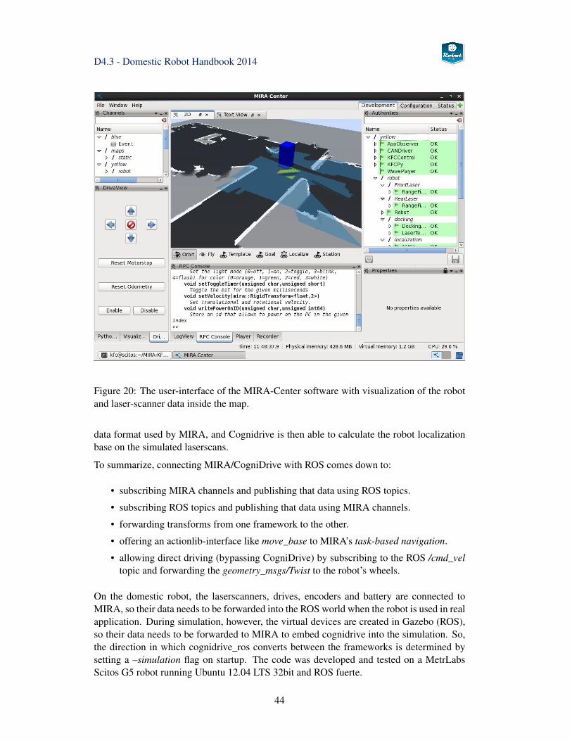
D4.3 - Domestic Robot Handbook 2014
Figure 20: The user-interface of the MIRA-Center software with visualization of the robotand laser-scanner data inside the map.
data format used by MIRA, and Cognidrive is then able to calculate the robot localizationbase on the simulated laserscans.
To summarize, connecting MIRA/CogniDrive with ROS comes down to:
• subscribing MIRA channels and publishing that data using ROS topics.
• subscribing ROS topics and publishing that data using MIRA channels.
• forwarding transforms from one framework to the other.
• offering an actionlib-interface like move_base to MIRA’s task-based navigation.
• allowing direct driving (bypassing CogniDrive) by subscribing to the ROS /cmd_veltopic and forwarding the geometry_msgs/Twist to the robot’s wheels.
On the domestic robot, the laserscanners, drives, encoders and battery are connected toMIRA, so their data needs to be forwarded into the ROS world when the robot is used in realapplication. During simulation, however, the virtual devices are created in Gazebo (ROS),so their data needs to be forwarded to MIRA to embed cognidrive into the simulation. So,the direction in which cognidrive_ros converts between the frameworks is determined bysetting a –simulation flag on startup. The code was developed and tested on a MetrLabsScitos G5 robot running Ubuntu 12.04 LTS 32bit and ROS fuerte.
44
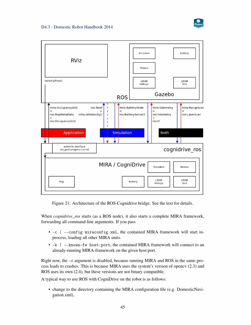
D4.3 - Domestic Robot Handbook 2014
Figure 21: Architecture of the ROS-Cognidrive bridge. See the text for details.
When cognidrive_ros starts (as a ROS node), it also starts a complete MIRA framework,forwarding all command-line arguments. If you pass
• -c | --config miraconfig.xml, the contained MIRA framework will start in-process, loading all other MIRA units.
• -k | --known-fw host:port, the contained MIRA framework will connect to analready-running MIRA-framework on the given host:port.
Right now, the -c argument is disabled, because running MIRA and ROS in the same pro-cess leads to crashes. This is because MIRA uses the system’s version of opencv (2.3) andROS uses its own (2.4), but these versions are not binary compatible.
A typical way to use ROS with CogniDrive on the robot is as follows:
• change to the directory containing the MIRA configuration file (e.g. DomesticNavi-gation.xml),
45
D4.3 - Domestic Robot Handbook 2014
• then start mira -c DomesticNavigation.xml. In this file, MIRA is instructed tolisten on xml:root -> communication -> port (e.g. port 1234).
• start cognidrive_ros -k 127.0.0.1:1234, so that the MIRA functions in cogni-drive_ros will connect to the instance of MIRA you started above.
• start cognidrive_ros -k 127.0.0.1:1234 --simulation when running in theGazebo simulator, so that MIRA is getting data from the simulator.
• start rosrun rviz rviz to visualize laserscans and transforms, set pose estimatesor 2D navigation goals.
• start miracenter and connect to the MIRA framework at address 127.0.0.1:1234 tosee the same things in MIRA.
Setting the initial robot pose When the robot is first started, it may not be localizedcorrectly. While the AMCL algorithm is capable of localizing the robot after some move-ments, it is usually safer to specify the (approximate) initial robot pose. This can be done bypublishing a pose to the /initialpose topic, for example when starting from a fixed, knownposition of the robot.
Alternatively, start rviz, then enable both the /map and the laser-scanner data /base_scan andoptionally /basescan_rear. Press the 2D Pose Estimate button from the button bar, click-and-hold the mouse at the approximate (x,y)-position of the robot, then drag the mouse tospecify the robot orientation Θ, and release the mouse to adopt this position. Repeat, untilthe laserscan data matches the map.
Setting the navigation goal To move the robot to a given position and orientation, simplypublish a pose goal to the /move_base_simple/goal topic. Again, this can also be doneinteractively in rviz via the 2D Nav Goal button in the button bar, then using click-and-holdto specify the (x,y) position of the target position, and finally using mouse-drag to selectthe Θ orientation of the robot. The robot motion will start as soon as the MIRA planner hascalculated an obstacle-avoiding motion plan, which can take a few seconds.
Creating the map The map required for localization can be drawn by hand, or can becreated by driving the robot around and using SLAM to build the map incrementally. Seethe MIRA tutorials and reference manual for details. When updating the map file in theMIRA configuration xml file, also check to adjust the offset and orientation of the map.
46
D4.3 - Domestic Robot Handbook 2014
3.3 Sensing and Perception
3.3.1 Overview
The domestic robot platform provides several different sensor systems.
• two laser range finders
• sonar sensors
• Asus Xtion Pro (RGB-D camera, comparable to Microsoft Kinect)
• RGB camera with tele-lens (firewire)
All different sensor systems are integrated in ROS in order to achieve:
• unified interface
• sharing devices between multiple subscribers.
3.3.2 Pan-Tilt Unit
The pan-tilt unit itself is an actuator system, but closely related to the sensory systems ofthe domestic robot, as it is used to change the direction of the Kinect- and RGB-cameras.
• ptu/cmd
• ptu/joint_states
rostopic pub -1 ptu/cmd sensor_msgs/JointState"{ header: { stamp: now },
name: [’ptu_pan_joint’, ’ptu_tilt_joint’],position: [1.57, 0], velocity: [0.5, 0.5] }"
3.3.3 Camera System and Image Processing
GStreamer-ROS-Adapter Due to several drawbacks in the gscam-node, we imple-mented an advanced ROS-GStreamer adapter
The open-source multimedia framework GStreamer [44] is used by many multimedia appli-cations under Linux. Many functions needed for these applications are already implementedin GStreamer, like format conversion, image resizing, encoding, decoding, timing and net-work data transmission. The GStreamer framework is plugin-based, so the functionalitycan be expanded by new elements that can also define their own data types. The elementsare connected to a processing pipeline, so that many operations can manipulate image dataconsecutively.
There are several reasons why we consider GStreamer as a suitable framework for handlinghigh bandwidth multimedia data on a robot system. These are mainly:
47
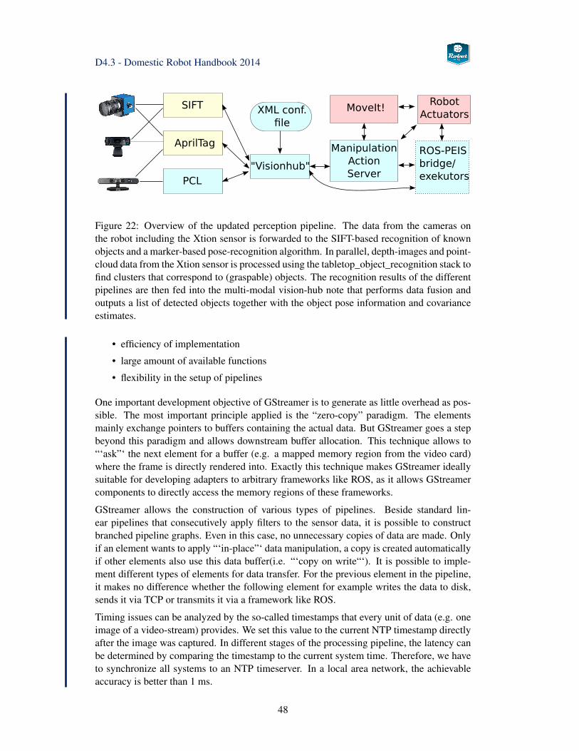
D4.3 - Domestic Robot Handbook 2014
Figure 22: Overview of the updated perception pipeline. The data from the cameras onthe robot including the Xtion sensor is forwarded to the SIFT-based recognition of knownobjects and a marker-based pose-recognition algorithm. In parallel, depth-images and point-cloud data from the Xtion sensor is processed using the tabletop_object_recognition stack tofind clusters that correspond to (graspable) objects. The recognition results of the differentpipelines are then fed into the multi-modal vision-hub note that performs data fusion andoutputs a list of detected objects together with the object pose information and covarianceestimates.
• efficiency of implementation
• large amount of available functions
• flexibility in the setup of pipelines
One important development objective of GStreamer is to generate as little overhead as pos-sible. The most important principle applied is the “zero-copy” paradigm. The elementsmainly exchange pointers to buffers containing the actual data. But GStreamer goes a stepbeyond this paradigm and allows downstream buffer allocation. This technique allows to“‘ask”‘ the next element for a buffer (e.g. a mapped memory region from the video card)where the frame is directly rendered into. Exactly this technique makes GStreamer ideallysuitable for developing adapters to arbitrary frameworks like ROS, as it allows GStreamercomponents to directly access the memory regions of these frameworks.
GStreamer allows the construction of various types of pipelines. Beside standard lin-ear pipelines that consecutively apply filters to the sensor data, it is possible to constructbranched pipeline graphs. Even in this case, no unnecessary copies of data are made. Onlyif an element wants to apply “‘in-place”‘ data manipulation, a copy is created automaticallyif other elements also use this data buffer(i.e. “‘copy on write“‘). It is possible to imple-ment different types of elements for data transfer. For the previous element in the pipeline,it makes no difference whether the following element for example writes the data to disk,sends it via TCP or transmits it via a framework like ROS.
Timing issues can be analyzed by the so-called timestamps that every unit of data (e.g. oneimage of a video-stream) provides. We set this value to the current NTP timestamp directlyafter the image was captured. In different stages of the processing pipeline, the latency canbe determined by comparing the timestamp to the current system time. Therefore, we haveto synchronize all systems to an NTP timeserver. In a local area network, the achievableaccuracy is better than 1 ms.
48
D4.3 - Domestic Robot Handbook 2014
The "rossink"-element will act as a sink for image data inside the GStreamer framework.During the start sequence of a pipeline, this element will advertise a camera in the ROS-framework. Usually, the following sequence of actions is performed for each frame:
• An upstream element requests a buffer.
• "rossink" creates a ROS "sensor_msgs/Image"-message and provides the pointer toits payload to the upstream element.
• The upstream element renders the image into the buffer and passes it to the "rossink".
• The "rossink" will look up and publish the "sensor_msgs/Image" based on the pointeradress
The "rossrc"-element acts as a source inside the GStreamer framework. It behaves likeelements that allow access to camera hardware and provides a sequence of image buffers.At the start of a pipeline, this element will subscribe to an arbitrary ROS-topic. This elementperforms the following sequence of actions:
• When a new message is received, a callback function is called.
• In the callback function, a GStreamer buffer is created and the memory address ispointed to the payload of the "sensor_msgs/Image"
• The GStreamer buffer is sent to the next element.
The "rossrc"-element will store properties of certain GStreamer elements on the ROS pa-rameter server. These parameters can be chosen manually. During runtime the elementwatches the parameters for changes on the parameter server and propagates them to thecorresponding element. This check is also performed vice versa.
One feature of our implementation is that it becomes possible to access cameras that are in-tegrated in ROS. Even simulated cameras (e.g. from Gazebo) can be use and the videostream can be handled in different ways (published via an RTSP server, recorded, dis-played).
Installation of the GStreamer-ROS libraries While for the first evaluation loop theGstreamer libraries had to be compiled seperately from the ROS workspace, they are nowincluded in the catkin workspace, are built whithin the catkin_make procedure and do notneed to be installed in the systems’ lib directories.
Usage The pipelines are started with the launch files, located in the gstreamer_pipelinesdirectory. They contain methods to run GStreamer Pipelines, for example the launch filedoro_right_camera.launch starts the following pipeline:
gst-launch dc1394src! queue leaky=2 max-size-buffers=1 ! ffmpegcolorspace! "video/x-raw-rgb , bpp=24, framerate=15/4"! timestamper t1=-1 t2=1! rossink topic=right_camera frame_id=RightCameraLens_link
camerafile=/etc/rightcamera.txt sync=0 peeralloc=1
49
D4.3 - Domestic Robot Handbook 2014
It is possible to adapt the framerate by changing the value 15/4 (=3.75 fps) to 15/2 (=7.5fps) or 15/1 (=15 fps). The camera calibration file is /etc/rightcamera.txt. Also, it is con-figured that the images will be published on the topic right_camera and the frame_id isRightCameraLens_link (the latter parameter matches the URDF file)
Calibrating the Camera In order to (re-) calibrate the camera, first the camera needs tobe started.
Terminal1: roscoreTerminal2: domestic_bringupConfigure the filename where the camera calibration files will be stored, you need to havewrite access it they should be updated automatically.
(on startup, the system may complain that it did not find the calibration file)
Type: "rostopic list"
gives you something like /leftcamera/image_raw
You can check this by running:
rosrun image\_view image\_view image:=/leftcamera/image\_raw
With the calibration pattern found in Orebro living lab:
rosrun camera\_calibration cameracalibrator.py--size 8x6 --square 0.02986image:=/leftcamera/image\_raw transport:=compressedcamera:=/leftcamera
With the PR2 calibration pattern pattern:
rosrun camera\_calibration cameracalibrator.py--size 5x4 --square 0.0245image:=/leftcamera/image\_raw camera:=/leftcamera
Run/rerun the command from above:
• Move the checkerboard to all corners, turn it around, until about 50 images are cap-tured.
• The green "Calibrate" button will be available - press it
• Be patient - window will hang for about 30 seconds, but it is NOT crashed !!
• Adjust the imagesize with the slider
• either save - saves raw data to /tmp - look at the console output (you manually haveto copy the txt file to /etc/leftcamera.txt)
50
D4.3 - Domestic Robot Handbook 2014
• or commit: advises the camera node to store the value internally - overwrites thecamera config file /etc/leftcamera.txt
• if you get an error message, probably the Gstreamer-ROS has no write access to thefile (see note from above)
For additional info, see http://www.ros.org/wiki/camera_calibration
In the current OpenCV libraries from ROS Groovy, there is a bug leading to a crash in thecalibration routine. Here is a workaround: NOTE: This Only needs to be done once, andonly, if camera_calibration crashes. It may be necessary to reinstall OpenCV after an updateof the OpenCV libs (e.g. after "sudo apt-get upgrade")
Install OpenCV from the scratch... overwriting the previous...
• find out which opecv version is installed
– cd /opt/ros/groovy
– find . | grep libopencv
– the output is something like 2.4.4
• get the 2.4.4 Source...(in case you have installed the latest groovy updates, otherwise2.4.3)
• unpack the sources
• backup your ROS folder:
– cd /opt/ros
– tar czf groovy_backup.tar.gz groovy/
• cmake -DCMAKE_INSTALL_PREFIX:PATH=/opt/ros/groovy .
• sudo make install
This will overwrite the OpenCV libs installed from the ROS repository.
Publishing Rectified Images In order to use publish rectified image, the "image_proc"node is startet in the cameras.launch file with the call:
ROS_NAMESPACE="/leftcamera" rosrun image_proc image_proc
Check "rostopic list" in order to see the aditional topics.
Example: Display the Rectified image:rosrun image_view image_view image:=/leftcamera/image_rect_color
For additional info, see http://www.ros.org/wiki/image_proc
51
D4.3 - Domestic Robot Handbook 2014
3.3.4 XtionPro RGB-D Camera and Point-Clouds
If
roslaunch openni\_launch openni.launch
can not be executed, we have to re-install it seperately. sudo apt-get install ros-hydro-openni-launch
Starting the tabletop segmentation:
roslaunch tabletop\_object\_detector tabletop\_segmentation.launchtabletop\_segmentation\_points\_in:=/xtion\_camera/depth/points
Check whether the object detector works:
roscd tabletop_object_detectorbin/ping_tabletop_node
The return values have the following meanings:
• Error 1: No cloud received
• Error 2: No Table detected
• Error 3: Other Error (see console output of tabletop_segmentation.launch console,problems with TF are always a hot candidate for errors)
• Return Value 4: No error
3.3.5 MJPEG-Server 2
ROS provides the possibility to stream arbitrary video topics directly to a browser (includ-ing mobile devices). The MJPEG-Server has been extended in order to support modernbrowsers and to save and load snapshots of the current scene. The package is called’"mjpeg_server2’" and is located in the Catkin-Workspace of the Robot-Era software repos-itory.
Manual start:
rosrun mjpeg_server2 mjpeg_server2 in order to start the Webserver on port 8080.
In order to start it on a different port, run:rosrun mjpeg_server2 mjpeg_server2 _port:=8081
You can connect to the video streams using your webbrowser and opening the adress:http://$ROBOT:8080/stream?topic=/leftcamera/image_raw
Where $ROBOT has to be replaced with the hostname or IP of the robot (“doro”).
The command above will make the webserver subscribe to the Topic /leftcamera/im-age_raw, you can use it the same way for other ropics. In order to change the resolution orquality (in order to save bandwidth), you can use
http://$ROBOT:8080/stream?topic=/leftcamera/image_raw?width=320?height=240?quality=40
Quality can be chosen from 1 (lowest) to 100 (highest).
doro.informatik.uni-hamburg.de:8081/stream?topic=/xtion_camera/depth/image
52
D4.3 - Domestic Robot Handbook 2014
MJPEG-Server2 - Additional Features Due to a long-standing bug in Firefox (https://bugzilla.mozilla.org/show_bug.cgi?id=984362) and due to a regression of not supportingraw MJPEG streams any longer in Webkit based browsers (https://productforums.google.com/forum/#!topic/chrome/PslmTeeM8Fo), the MJPEG-server had to be adapted. If thestream is embedded into a web page, it is displyed correctly with both browsers. Whenaccessing the adress
http://$ROBOT:8080/embeddedstream?topic=/leftcamera/image_raw
a simple html-website is delivered with an embedded stream. The parameters to configurethe image topic and resolution is exactly the same as explained on the project website.Internally, from this website the browser will then call
http://$ROBOT:8080/stream?topic=/leftcamera/image_raw
while passing through all your parameters.
Additional functions:
Sometimes it might be useful to store and load images, for example when detecting an eventlike an intruder. There are two different options how the images can be saved: in RAM usingslot 0..9 or persistently to files.
Saving a snapshot to slots (RAM):http://$ROBOT:8080/store?slot=1?topic=/leftcamera/image_raw
Saving snapshot to a file:http://$ROBOT:8080/store?topic=/leftcamera/image_raw?file=/path/to/filename.jpg
Loading images stored on a slot (If no image has been saved on this port you will get a 404error page.):
http://$ROBOT:8080/load?slot=1Loading images from a file:http://$ROBOT:8080/load?file=/path/to/filename.jpg
It is possible to adjust the width and height of the delivered image, append these parametersto the request, seperated by ’"?’" (default: native image size, only valid if both width andheight are specified) It is also possible to adjust the image quality this way (quality)
Example:http://tams115:8080/embeddedstream?topic=/leftcamera/image_raw?width=100?height=80?quality=40
Embedding the stream into a web page: It is possible to embed one or multiple (somebrowsers limit the number) streams into a web page, for example the UI for the robot.Sample HTML code:<html><body><img src="http://$ROBOT/stream?topic=/camera/image_raw"></body></html>Of course, the image size can be adapted like described above.
Note: It is only necessary to start one instance of the MJPEG-server to publish all availableROS-integrated cameras.
53
D4.3 - Domestic Robot Handbook 2014
3.3.6 Object Detection and Pose Estimation
The domestic robot platform provides three main object detection and localization algo-rithms:
• SIFT-based object detection
• PCL-based object detection (including SIFT based classification). In this case SIFTis only used to classify the defected point cloud by finding the best match in the objectdatabase.
• AprilTag Markers
The different methods and their results are managed by a component called Visionhub. Theconcept of this ROS node is shown in figure 22.
3.3.7 Visionhub
This is a ROS node that acts as an interface between nodes for image processing (currentlyAprilTags and SIFT is supported), manipulation/planning nodes. It has been built in orderto interface to an ontology or context awareness module that defines certain objects, buthas also built in functionality. The reason why this node has been implemented is that ona higher level (grasping/planning) you just want to know which objects have been detectedand what pose they have, but you want to hide the complexity of the underlying detectionprocess. So it is irrelevant for the action-planning-nodes doing manipulation whether thedetection has been done using SIFT or other algorithms or which cameras have taken theimage.
Basically the Visionhub node provides the following function to publish which objects aredetected and how they can be grasped. Therefore this node reads from a database, thatcontains the following information about objects:
• dimensions of the bounding box
• surfaces (image files) and their exact position
• AprilTag Markers and their size and position
• informations on grasps (grasppoints maximum force)
Visionhub: Defining Objects The long term plan is to support different types ofdatabases. Currently the objects need to be specified by an XML file. The file formatshould be self-explaining, a commented sample file is provided in the repository under:
The top level entity is “object”. This is usually an object (including other robots), or also aroom (in order to implement initial self localization). Beside the robot name, a box can bedefined. This can be either used as a bounding box for collisiond aware motion planning or
54
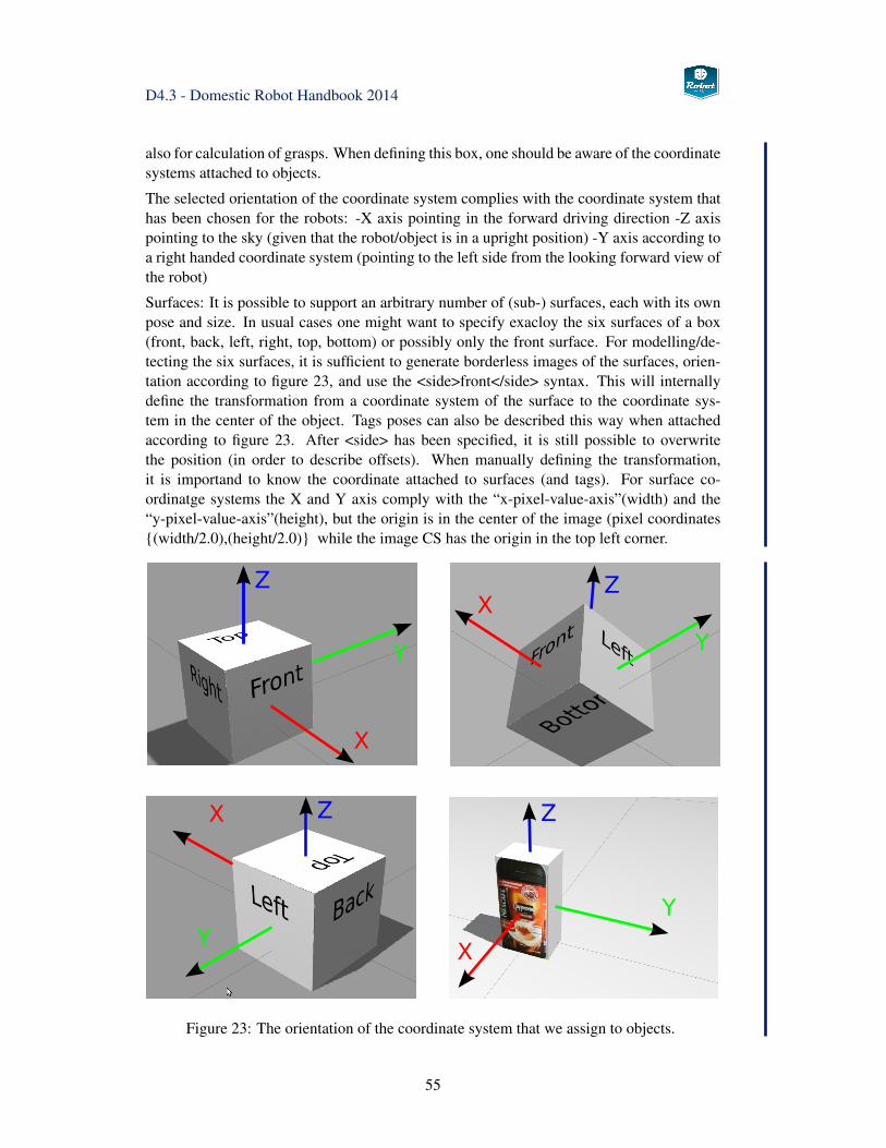
D4.3 - Domestic Robot Handbook 2014
also for calculation of grasps. When defining this box, one should be aware of the coordinatesystems attached to objects.
The selected orientation of the coordinate system complies with the coordinate system thathas been chosen for the robots: -X axis pointing in the forward driving direction -Z axispointing to the sky (given that the robot/object is in a upright position) -Y axis according toa right handed coordinate system (pointing to the left side from the looking forward view ofthe robot)
Surfaces: It is possible to support an arbitrary number of (sub-) surfaces, each with its ownpose and size. In usual cases one might want to specify exacloy the six surfaces of a box(front, back, left, right, top, bottom) or possibly only the front surface. For modelling/de-tecting the six surfaces, it is sufficient to generate borderless images of the surfaces, orien-tation according to figure 23, and use the <side>front</side> syntax. This will internallydefine the transformation from a coordinate system of the surface to the coordinate sys-tem in the center of the object. Tags poses can also be described this way when attachedaccording to figure 23. After <side> has been specified, it is still possible to overwritethe position (in order to describe offsets). When manually defining the transformation,it is importand to know the coordinate attached to surfaces (and tags). For surface co-ordinatge systems the X and Y axis comply with the “x-pixel-value-axis”(width) and the“y-pixel-value-axis”(height), but the origin is in the center of the image (pixel coordinates{(width/2.0),(height/2.0)} while the image CS has the origin in the top left corner.
Figure 23: The orientation of the coordinate system that we assign to objects.
55
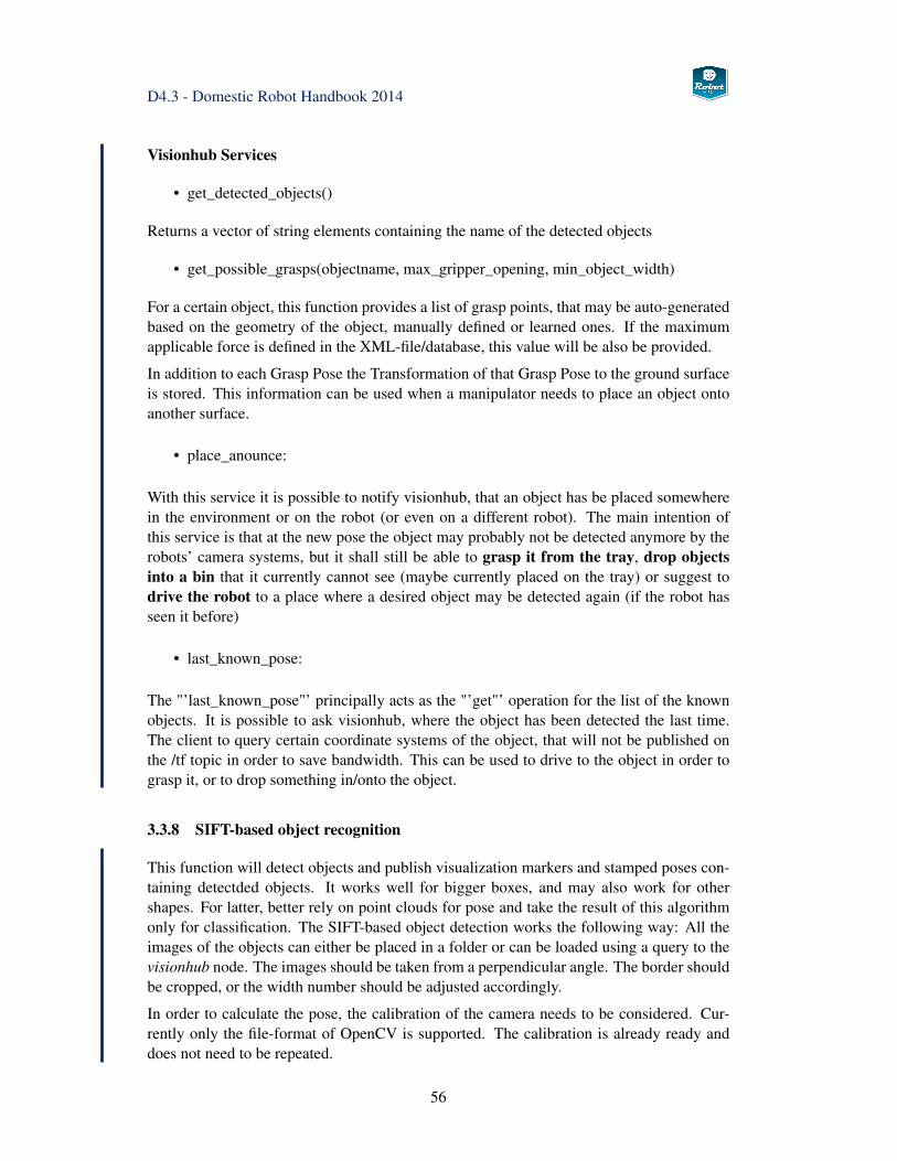
D4.3 - Domestic Robot Handbook 2014
Visionhub Services
• get_detected_objects()
Returns a vector of string elements containing the name of the detected objects
• get_possible_grasps(objectname, max_gripper_opening, min_object_width)
For a certain object, this function provides a list of grasp points, that may be auto-generatedbased on the geometry of the object, manually defined or learned ones. If the maximumapplicable force is defined in the XML-file/database, this value will be also be provided.
In addition to each Grasp Pose the Transformation of that Grasp Pose to the ground surfaceis stored. This information can be used when a manipulator needs to place an object ontoanother surface.
• place_anounce:
With this service it is possible to notify visionhub, that an object has be placed somewherein the environment or on the robot (or even on a different robot). The main intention ofthis service is that at the new pose the object may probably not be detected anymore by therobots’ camera systems, but it shall still be able to grasp it from the tray, drop objectsinto a bin that it currently cannot see (maybe currently placed on the tray) or suggest todrive the robot to a place where a desired object may be detected again (if the robot hasseen it before)
• last_known_pose:
The "’last_known_pose"’ principally acts as the "’get"’ operation for the list of the knownobjects. It is possible to ask visionhub, where the object has been detected the last time.The client to query certain coordinate systems of the object, that will not be published onthe /tf topic in order to save bandwidth. This can be used to drive to the object in order tograsp it, or to drop something in/onto the object.
3.3.8 SIFT-based object recognition
This function will detect objects and publish visualization markers and stamped poses con-taining detectded objects. It works well for bigger boxes, and may also work for othershapes. For latter, better rely on point clouds for pose and take the result of this algorithmonly for classification. The SIFT-based object detection works the following way: All theimages of the objects can either be placed in a folder or can be loaded using a query to thevisionhub node. The images should be taken from a perpendicular angle. The border shouldbe cropped, or the width number should be adjusted accordingly.
In order to calculate the pose, the calibration of the camera needs to be considered. Cur-rently only the file-format of OpenCV is supported. The calibration is already ready anddoes not need to be repeated.
56
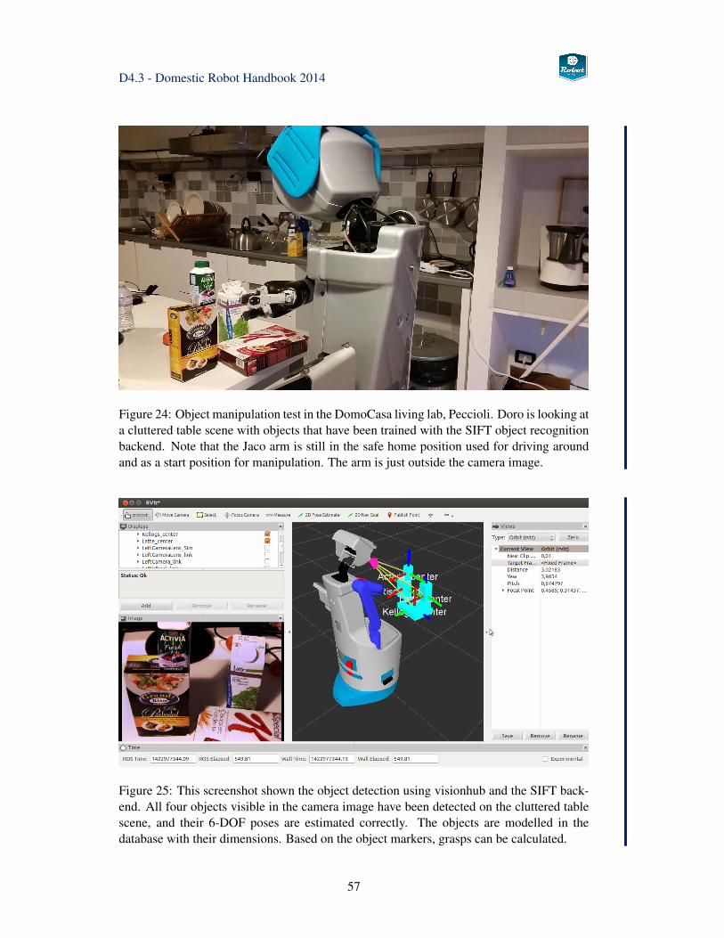
D4.3 - Domestic Robot Handbook 2014
Figure 24: Object manipulation test in the DomoCasa living lab, Peccioli. Doro is looking ata cluttered table scene with objects that have been trained with the SIFT object recognitionbackend. Note that the Jaco arm is still in the safe home position used for driving aroundand as a start position for manipulation. The arm is just outside the camera image.
Figure 25: This screenshot shown the object detection using visionhub and the SIFT back-end. All four objects visible in the camera image have been detected on the cluttered tablescene, and their 6-DOF poses are estimated correctly. The objects are modelled in thedatabase with their dimensions. Based on the object markers, grasps can be calculated.
57
D4.3 - Domestic Robot Handbook 2014
The node publishes on the topic "siftobjects", type <visualization_msgs::Marker> that putsout ALL detected objects for vizualization in Rviz. If an object is no longer detected, itpublishe one "DELETE"-message according to the specification of the message typ.
"siftobjects/objectname", type <geometry_msgs::PoseStamped> one topic for each object.NOTE: only advertised if the object is detected the first time. No delete message is sent, soplease look at the timestamp.
"tf" type <tf/tfMessage> This type of message describes the transformation between thecamera- and the object-coordinate frame.
Using the tf-system of ROS it is easy to obtain other transformations like robot_base toobject or gripper to object.
The SIFT implementation is included in the catkinized gstreamer_pipeline directory, inter-nally for example the start_siftserver_right.launch file starts the following pipeline:
LD_PRELOAD=/opt/ros/groovy/lib/libimage_transport.sogst-launch rossrc topic=right_camera/image_raw
! queue leaky=2 max-size-buffers=1 ! ffmpegcolorspace! siftextractor! rossiftserver
caminfotopic=right_camera/camera_infoimdbsrv=/get_image_sizes
! fakesink
This node can be configured as follows:
• imdbsrv=/get_image_sizesspecifies a ROS-service (Visionhub) to look up which image files should be used formatching and what physical size the surfaces have.
• caminfotopic=right_camera/camera_infospecifies the camera-info topic to retrieve the calibration parameters for the selectedcamera automatically.
• alternatively, you can specify the directory where the calibration parameters (Disto-rions.xml and Intrinsics.xml) are stored via this parameter:unddirectory=/localhome/demo/camera_calib_data/cal_April2013
3.3.9 AprilTag Marker detection
The integration of AprilTags has been done using an existing ROS node that has been ex-tended in many ways. The following additional features have been implemented:
• automatically read out camera calibration from the corresponding topic
• support for markers with different sizes (configured through the “visionhub” node)
• high performance tracking of detected markers
• performance improvements and bug fixes
58
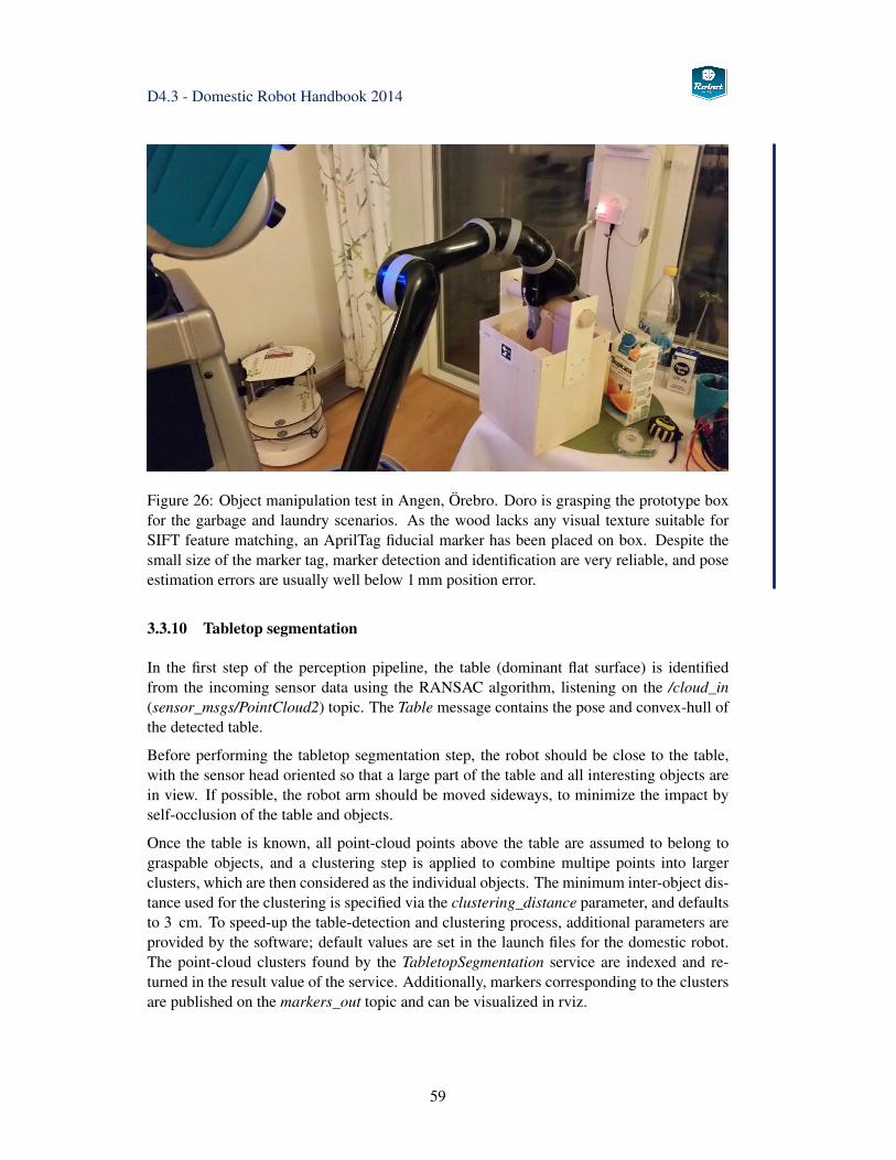
D4.3 - Domestic Robot Handbook 2014
Figure 26: Object manipulation test in Angen, Örebro. Doro is grasping the prototype boxfor the garbage and laundry scenarios. As the wood lacks any visual texture suitable forSIFT feature matching, an AprilTag fiducial marker has been placed on box. Despite thesmall size of the marker tag, marker detection and identification are very reliable, and poseestimation errors are usually well below 1 mm position error.
3.3.10 Tabletop segmentation
In the first step of the perception pipeline, the table (dominant flat surface) is identifiedfrom the incoming sensor data using the RANSAC algorithm, listening on the /cloud_in(sensor_msgs/PointCloud2) topic. The Table message contains the pose and convex-hull ofthe detected table.
Before performing the tabletop segmentation step, the robot should be close to the table,with the sensor head oriented so that a large part of the table and all interesting objects arein view. If possible, the robot arm should be moved sideways, to minimize the impact byself-occlusion of the table and objects.
Once the table is known, all point-cloud points above the table are assumed to belong tograspable objects, and a clustering step is applied to combine multipe points into largerclusters, which are then considered as the individual objects. The minimum inter-object dis-tance used for the clustering is specified via the clustering_distance parameter, and defaultsto 3 cm. To speed-up the table-detection and clustering process, additional parameters areprovided by the software; default values are set in the launch files for the domestic robot.The point-cloud clusters found by the TabletopSegmentation service are indexed and re-turned in the result value of the service. Additionally, markers corresponding to the clustersare published on the markers_out topic and can be visualized in rviz.
59
D4.3 - Domestic Robot Handbook 2014
3.3.11 Human Detection and Recognition
For the second experimental loop, human detection and recognition software will be testedon the Domestic and Condominium robots. The detection modules have be encapsulated asPEIS exekutor services, and the information can be merged with the ambient sensor data(e.g. chair switches, wearable sensors) by the configuration planner. See section 4.2.15 onpage 130 for details and the tuple definitions.
As people tracking is a common tasks, several independent ROS packages are available andhave been evaluated:
• The person_detection stack uses functions from the PCL library and a pre-trainedSVM to detect people in the pointclouds generated by the Kinect/Xtion sensor. Thealgorithm publishes the head positions of detected persons as well as their estimatedmotion with respect to the robot. The stack has been tuned and refined by UHAM toimprove robustness and the detection of sitting people.
This algorithm is currently used on Domestic robot for the find_user service. Workhas been started to also include face detection and face recognition algorithms tofurther improve recogntion rates.
• The openni_tracker package is based on the people movement tracking originallydeveloped for the Microsoft Kinect sensor. The current implementation is based onthe NiTE tracking library from PrimeSense, and ready-to-run installers exist for ROSHydro. The software directly accesses the depth-image from a Kinect/Xtion sensorsand detects and tracks up to six persons simultaneously. Once the so-called Psi-poseis detected for a person (standing with the upper arms extended and the lower armspointing upwards), a calibration sequence starts and afterwards the library tracks theusers’ head, arms, and legs. The corresponding poses are published as individualtransformations to the ROS tf system.
The tracking detects standing and sitting people, and can track moving people evenwith occlusions. However, the tracker is not suitable for people that are lying ona bed or on the floor. The ROS node only publishes arm and leg information aftercalibration has been performed for a person.
Unfortunately, the original (openni) software is not compatible with the XtionProsensor mounted on the Domestic robot. While a replacement library (NiTE2, openni2)is available, the new library requires exclusive access to the sensor, so that image andpoint-cloud data is no longer available to other ROS nodes.
• The ROS people detection stack consists of several independent modules optimizedfor different usage scenarios. The leg_detector searches for legs in 2D laser scans,and people_tracking_filter in turn uses the candidate legs to identify and track movingpeople. The face_detector uses OpenCV image processing to find faces in 2D cameraimages. See wiki.ros.org/people for details. Unfortunately, little documentation isavailable for the different software modules.
• The cob_people_detection stack combines the OpenNI person tracking with face-detection and face-recognition (Eigenfaces, Fisherfaces) to identify known persons.
60
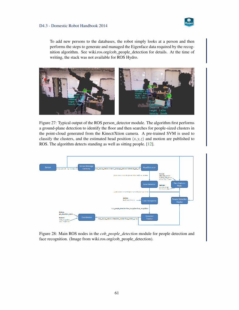
D4.3 - Domestic Robot Handbook 2014
To add new persons to the databases, the robot simply looks at a person and thenperforms the steps to generate and managed the Eigenface data required by the recog-nition algorithm. See wiki.ros.org/cob_people_detection for details. At the time ofwriting, the stack was not available for ROS Hydro.
Figure 27: Typical output of the ROS person_detector module. The algorithm first performsa ground-plane detection to identify the floor and then searches for people-sized clusters inthe point-cloud generated from the Kinect/Xtion camera. A pre-trained SVM is used toclassify the clusters, and the estimated head position (x,y,z) and motion are published toROS. The algorithm detects standing as well as sitting people. [12].
Figure 28: Main ROS nodes in the cob_people_detection module for people detection andface recognition. (Image from wiki.ros.org/cob_people_detection).
61
D4.3 - Domestic Robot Handbook 2014
3.4 Manipulation
Object manipulation with robots is standard industry practice by today, but the typical fac-tory solution is characterized by a strictly controlled environment and highly regular tasks.The robots are equipped with grippers and tools matched to the particular target objects,robot and object positions are known, and trajectories may be hardcoded. Sensor feed-back, if used at all, is only required for slight corrections and adaptations to initial objectpositions.
In the context of service robots, however, manipulation is still unsolved and remains oneof the key research challenges. Even for apparantly simple tasks like picking up an object,several complex subproblems must be tackled. First, perception algorithms must be able todetect the object in a potentially cluttered environment, and then to estimate the object posein regard to the current robot position. As full scene understanding is far beyond the reachof computer vision, simplifications are required.
Second, to reach the target object a collision-free robot arm trajectory must be calculated,leading to complex motion-planning problems depending on the number and complexity ofobstacles. Picking up a single mug from a table is easy, but putting the same mug into adishwasher full of other objects is very challenging. Once the object is grasped, the motion-planning must take the object into account when calculation new trajectories.
Third, to grasp an object the robot gripper or hand must be configured to reach suitable con-tact points on the object, and to apply forces that allow to lift the object against gravity andstabilize the grasp against disturbances in free space. Fourth, manipulation often involvesmoving an object in contact to other objects, applying forces depending on the task context.For example, swiping a table, opening a door, or turning a screw requires highly precisemotions that take the kinematic structure of the environment into account.
According to the tasks described in the Robot-Era scenario storybooks, all of the aboveproblems need to be tackled and implemented on the domestic robot. As explained inchapter 4 below, an incremental approach is taken. First, simple reach and grasp motions reimplemented for the robot, which are then refined and integrated with perception to morecomplex tasks. As force-control is not available on the Kinova Jaco arm, it remains to beseen to which extent actual manipulation motions can be realized.
The next section 3.5 first summarizes the key features of the Kinova Jaco robot and thesoftware architecture to control the arm and gripper. Next, section 3.6 sketches the recentMoveIt! framework, that is used for the manipulation tasks in the second experimental loopand has completely replaced the priorly used manipulation stack on the Domestic robot.MoveIt! is under heavy development, but we expect to track the progress and use the ad-vanced manipulation capabilities, adapted to the Kinova gripper, for the domestic robot.
In section 3.7 the service node is described that actually connects to the MoveIt and Vi-sionhub and provides higher level services (e.g. grasp object), that are then called by theexecutor nodes, which then export the functionality to the PEIS framework.
62
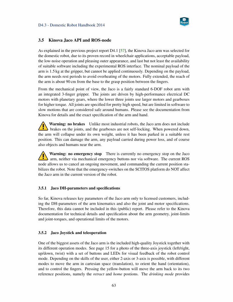
D4.3 - Domestic Robot Handbook 2014
3.5 Kinova Jaco API and ROS-node
As explained in the previous project report D4.1 [57], the Kinova Jaco arm was selected forthe domestic robot, due to its proven record in wheelchair applications, acceptable payload,the low-noise operation and pleasing outer appearance, and last but not least the availabilityof suitable software including the experimental ROS interface. The nominal payload of thearm is 1.5 kg at the gripper, but cannot be applied continuously. Depending on the payload,the arm needs rest periods to avoid overheating of the motors. Fully extended, the reach ofthe arm is about 90 cm from the base to the grasp position between the fingers.
From the mechanical point of view, the Jaco is a fairly standard 6-DOF robot arm withan integrated 3-finger gripper. The joints are driven by high-performance electrical DCmotors with planetary gears, where the lower three joints use larger motors and gearboxesfor higher torque. All joints are specified for pretty high speed, but are limited in software toslow motions that are considered safe around humans. Please see the documentation fromKinova for details and the exact specification of the arm and hand.
Warning: no brakes Unlike most industrial robots, the Jaco arm does not includebrakes on the joints, and the gearboxes are not self-locking. When powered down,
the arm will collapse under its own weight, unless it has been parked in a suitable restposition. This can damage the arm, any payload carried during power loss, and of coursealso objects and humans near the arm.
Warning: no emergency stop There is currently no emergency stop on the Jacoarm, neither via mechanical emergency buttons nor via software. The current ROS
node allows us to cancel an ongoing movement, and commanding the current position sta-bilizes the robot. Note that the emergency-switches on the SCITOS platform do NOT affectthe Jaco arm in the current version of the robot.
3.5.1 Jaco DH-parameters and specifications
So far, Kinova releases key parameters of the Jaco arm only to licensed customers, includ-ing the DH-parameters of the arm kinematics and also the joint and motor specifications.Therefore, this data cannot be included in this (public) report. Please refer to the Kinovadocumentation for technical details and specification about the arm geometry, joint-limitsand joint-torques, and operational limits of the motors.
3.5.2 Jaco Joystick and teleoperation
One of the biggest assets of the Jaco arm is the included high-quality Joystick together withits different operation modes. See page 15 for a photo of the three-axis joystick (left/right,up/down, twist) with a set of buttons and LEDs for visual feedback of the robot controlmode. Depending on the skills of the user, either 2-axis or 3-axis is possible, with differentmodes to move the arm in cartesian space (translation), to orient the hand (orientation),and to control the fingers. Pressing the yellow-button will move the arm back to its tworeference positions, namely the retract and home postions. The drinking mode provides
63
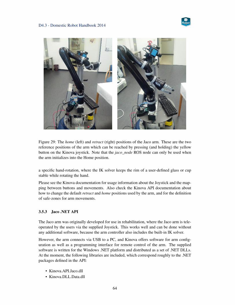
D4.3 - Domestic Robot Handbook 2014
Figure 29: The home (left) and retract (right) positions of the Jaco arm. These are the tworeference positions of the arm which can be reached by pressing (and holding) the yellowbutton on the Kinova joystick. Note that the jaco_node ROS node can only be used whenthe arm initializes into the Home position.
a specific hand-rotation, where the IK solver keeps the rim of a user-defined glass or cupstable while rotating the hand.
Please see the Kinova documentation for usage information about the Joystick and the map-ping between buttons and movements. Also check the Kinova API documentation abouthow to change the default retract and home positions used by the arm, and for the definitionof safe-zones for arm movements.
3.5.3 Jaco .NET API
The Jaco arm was originally developed for use in rehabilitation, where the Jaco arm is tele-operated by the users via the supplied Joystick. This works well and can be done withoutany additional software, because the arm controller also includes the built-in IK solver.
However, the arm connects via USB to a PC, and Kinova offers software for arm config-uration as well as a programming interface for remote control of the arm. The suppliedsoftware is written for the Windows .NET platform and distributed as a set of .NET DLLs.At the moment, the following libraries are included, which correspond roughly to the .NETpackages defined in the API:
• Kinova.API.Jaco.dll• Kinova.DLL.Data.dll
64
D4.3 - Domestic Robot Handbook 2014
• Kinova.DLL.Tools.dll• Kinova.DLL.USBManager.dll• Kinova.DLL.TestData.dll• Kinova.DLL.CommData.dll• Kinova.DLL.TcpConnector.dll• Kinova.DLL.SafeGate.dll
Kinova also supplies a Jaco arm control and configuration program. Its main user-interfaceprovides access to the arm parameters and allows the user to configure the joystick, the saferegions to be avoided by the arm during movements, and the maximum speed. There is alsoa simple self-test, and a small set of example programs for C# and VBASIC. However, theexample programs only use a very small subset of the API included by the Kinova runtimelibraries.
Fortunately, the mono software environment can be used to wrap the .NET libraries onLinux. This avoids the additional complexity of using a separate control PC or a virtualmachine for controlling the Jaco arm from the domestic robot and its ROS system. You needto install mono-devel and mono-gmcs software packages and their dependencies. It may alsobe required to install the lastest version of libusb-devel for reliable USB communicationwith the arm controller.
At the moment, Kinova Release 4.0.5 (April 2010) is installed on both domestic robot proto-types; an update to the recently released research version 5.0.1 (February 2013) is planned.A large part of the Kinova API is dedicated to configuration functions required for tele-operation via the joystick, in particular the mapping from joystick buttons and axes to carte-sian movements of the arm and gripper. Please see the Kinova Jaco User Guide and theJaco API Programming Guide for details.
The CJacoArm structure is the basic abstraction of one arm, and is initalized via a call to thearm constructor, which expects the license key provided by Kinova as the password. Onceinitialized, the CJacoArm structure provides access to several members, namely the Config-urationsManager, ControlManager, and DiagnosticManager. Before calling any other APIfunction, the JacoIsReady() checks whether the arm is initialized and running, and shouldbe called before any other function of the API.
The ConfigurationManager can be queried for the current arm configuration and parame-ters, e.g. the MaxLinearSpeed of the arm. Most arm parameters can be set by calling thecorresponding Set functions. The ConfigurationManager is also used to define the Con-trolMappings and events for the joystick and any ProtectionZones that the arm is forbiddento enter. The DiagnosticManager is used for debugging, maintenance, and allows resettingthe arm configuration to the factory defaults.
The ControlManager provides the functions relevant to autonomous robot control. Onlyjoint position control and cartesian position control are supported at the moment. There areno tactile sensors on the arm and fingers, and force control is not supported. However, arough estimate of joint-torques is available via measurement of the motor currents.
Important functions calls (and relevant parameters) are:
• GetAPIVersion Kinova API software version
65
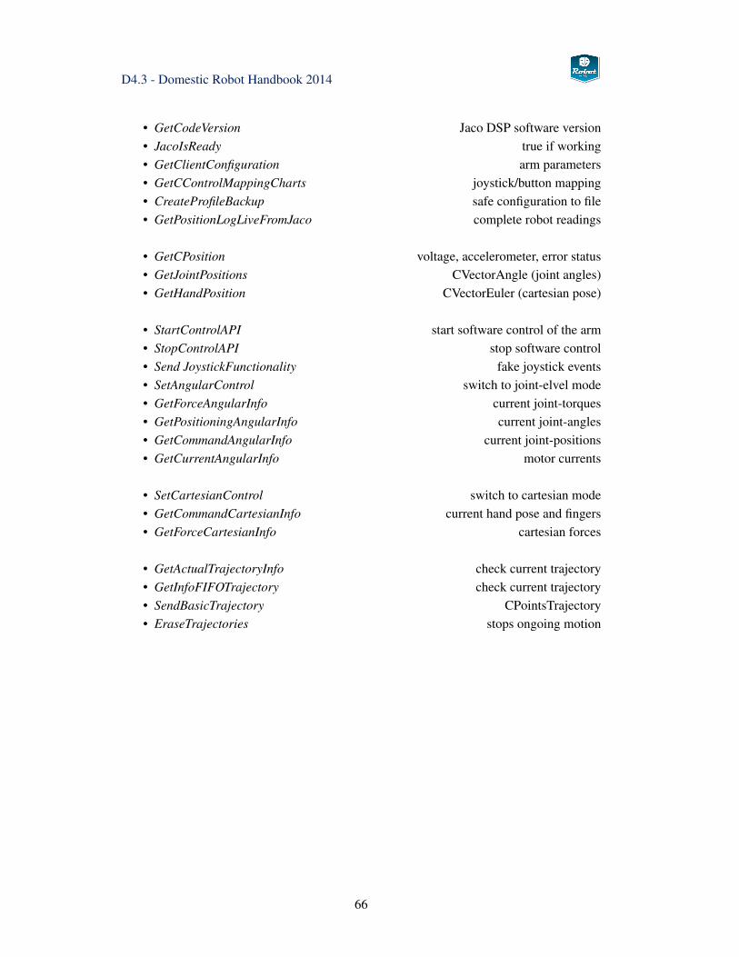
D4.3 - Domestic Robot Handbook 2014
• GetCodeVersion Jaco DSP software version• JacoIsReady true if working• GetClientConfiguration arm parameters• GetCControlMappingCharts joystick/button mapping• CreateProfileBackup safe configuration to file• GetPositionLogLiveFromJaco complete robot readings
• GetCPosition voltage, accelerometer, error status• GetJointPositions CVectorAngle (joint angles)• GetHandPosition CVectorEuler (cartesian pose)
• StartControlAPI start software control of the arm• StopControlAPI stop software control• Send JoystickFunctionality fake joystick events• SetAngularControl switch to joint-elvel mode• GetForceAngularInfo current joint-torques• GetPositioningAngularInfo current joint-angles• GetCommandAngularInfo current joint-positions• GetCurrentAngularInfo motor currents
• SetCartesianControl switch to cartesian mode• GetCommandCartesianInfo current hand pose and fingers• GetForceCartesianInfo cartesian forces
• GetActualTrajectoryInfo check current trajectory• GetInfoFIFOTrajectory check current trajectory• SendBasicTrajectory CPointsTrajectory• EraseTrajectories stops ongoing motion
66
D4.3 - Domestic Robot Handbook 2014
Kinova does not specify the maximum rate allowed for calling the different functions, butthe provided examples typically sample the joint-positions at 10 Hz. This should be suffi-cient for the first experiments in pure position control, but a much higher sample-rate andcommand-update rate will be required for fine motions and pseudo-force control imple-mented on top of a position-control loop.
Note that the software control of the arm is considered the lowest priority of all controlmethods of the Jaco. If the USB connection is lost, or if the Joystick is used, the softwarecontrol is disabled similar to a call to StopControlAPI.
The CPosition structure includes some low-level information that can be useful for improvedcontrol. It contains the age of the robot since manufacture, the error status flag, the lateralityflag (right-handed or left-handed arm), the retract state, the current supply voltage, built-inaccelerometer readings, and several overload detection flags.
The default coordinate system used for Jaco cartesian control is right-handed with the x-axisto the left, y-axis to the rear (negative y is to the front), and z-axis upwards. This has beendeduced experimentally when commanding poses with respect to the jaco_base_link link.
Therefore, the orientation of the coordinate system is different from the basic ROS coordi-nate system, and care must be taken when converting between (x,y,z) and (XΘ,Y Θ,ZΘ)angles for the Jaco GetHandPosition, GetCommandCartesianInfo and SetCartesianControlfunctions and ROS.
3.5.4 Jaco ROS integration
Despite its beta-status, the Kinova ROS stack already provides all major components foruse of the Jaco arm in ROS. The jaco_description package contains the URDF model of thearm, the jaco_api package builds a C++ library that wraps the Kinova .NET DLLS, and thejaco_node package defines the jaco_node ROS node that communicates with the arm forreal-time control. The stack also includes a set of launch and configuration files for ROSmanipulation stack.
The jaco_node is the most important component. At the moment, the node initializes thefollowing subscribers and publishers.
Subscribers:
• jaco_node/cur_goal (geometry_msgs/PoseStamped)• hand_pose (geometry_msgs/PoseStamped)• joint_states (sensor_msgs/JointState)• jaco_kinematic_chain_controller/follow_joint_trajectory/result• jaco_kinematic_chain_controller/follow_joint_trajectory/feedback• jaco_kinematic_chain_controller/follow_joint_trajectory/status
Publishers:
• hand_pose (geometry_msgs/PoseStamped)
67
D4.3 - Domestic Robot Handbook 2014
• cmd_abs_finger (jaco_node/FingerPose)• cmd_abs_joint (jaco_node/JointPose)• cmd_rel_cart (geometry_msgs/Twist)• jaco_kinematic_chain_controller/follow_joint_trajectory/goal
(control_msgs/FollowJointTrajectoryActionGoal.msg) Note that the current imple-mentation of this publisher ignores the velocity, acceleration and time values infor-mation.
• jaco_kinematic_chain_controller/follow_joint_trajectory/cancelThis publisher is not working (no implementation)
To move the arm to a joint-space position via the command line, just publish the correspond-ing joint angles (in radians, starting from the shoulder_yaw joint) the /cmd_abs_joint/topic:
rostopic pub -1 cmd_abs_joint jaco_node/JointPose"joints: [-1.7, -1.5, 0.8,-0.6, 1.5,-2.8]"
The joint-pose is published on /jaco/joint_states and is also available as part of the global/joint_states message,
rostopic echo /jaco/joint_states
To move the fingers to a given position (in radians):
rostopic pub -1 cmd_abs_finger jaco_node/FingerPose"fingers: [0.5, 0.5, 0.5]"
To move the Jaco arm to an absolute position in cartesian space (using the given ROScoordinate system, e.g. the arm base jaco_base_link or the robot base base_link):
rostopic pub -1 hand_goal geometry_msgs/PoseStamped’{ header: { frame_id: "base_link" },
pose: { position: { x: 0.23, y: -0.23, z: 0.45},orientation: { x: -0.62, y: -0.3, z: -0.3, w: -0.65 }}}’
The absolute position of the arm is published on the hand_pose topic, but this seems not tobe reliable in the current software version:
rostopic echo /hand_pose
Setting the relative position in cartesian space is also documented, but does not yet work:
rostopic pub -1 cmd_rel_cart geometry_msgs/Twist"{linear: {x: 10.0, y: 0.0, z: 0.0},
angular: { x: 0.0, y: 0.0, z: 0.0} }"
68
D4.3 - Domestic Robot Handbook 2014
The doro_description/scripts directory collects a set of small utility shell-scripts that encap-sulate the verbose rostopic pub messages documented above. For example,
rosrun doro_description jaco_home.shrosrun doro_description jaco_retract.shrosrun doro_description jaco_fingers.sh 0 0 0rosrun doro_description jaco_joints.sh -1.57 0.04 -1.1 -0.84 1.3 3.0rosrun doro_description jaco_xyz.sh 1.45 -0.40 0.38
will move the arm to the home position using joint-space interpolation, open the fingers,move the arm to the given joint-level position, move the arm to the given (x,y,z) posekeeping current orientation using Kinova inverse-kinematics.
69
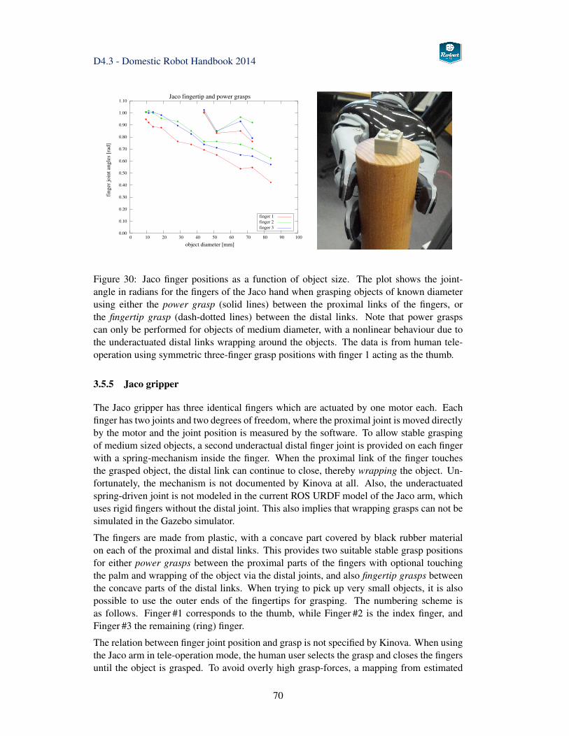
D4.3 - Domestic Robot Handbook 2014
1.10
1.00
0.90
0.80
0.70
0.60
0.50
0.40
0.30
0.20
0.10
0.001009080706050403020100
fing
er jo
int a
ngle
s [r
ad]
object diameter [mm]
Jaco fingertip and power grasps
finger 3finger 2finger 1
Figure 30: Jaco finger positions as a function of object size. The plot shows the joint-angle in radians for the fingers of the Jaco hand when grasping objects of known diameterusing either the power grasp (solid lines) between the proximal links of the fingers, orthe fingertip grasp (dash-dotted lines) between the distal links. Note that power graspscan only be performed for objects of medium diameter, with a nonlinear behaviour due tothe underactuated distal links wrapping around the objects. The data is from human tele-operation using symmetric three-finger grasp positions with finger 1 acting as the thumb.
3.5.5 Jaco gripper
The Jaco gripper has three identical fingers which are actuated by one motor each. Eachfinger has two joints and two degrees of freedom, where the proximal joint is moved directlyby the motor and the joint position is measured by the software. To allow stable graspingof medium sized objects, a second underactual distal finger joint is provided on each fingerwith a spring-mechanism inside the finger. When the proximal link of the finger touchesthe grasped object, the distal link can continue to close, thereby wrapping the object. Un-fortunately, the mechanism is not documented by Kinova at all. Also, the underactuatedspring-driven joint is not modeled in the current ROS URDF model of the Jaco arm, whichuses rigid fingers without the distal joint. This also implies that wrapping grasps can not besimulated in the Gazebo simulator.
The fingers are made from plastic, with a concave part covered by black rubber materialon each of the proximal and distal links. This provides two suitable stable grasp positionsfor either power grasps between the proximal parts of the fingers with optional touchingthe palm and wrapping of the object via the distal joints, and also fingertip grasps betweenthe concave parts of the distal links. When trying to pick up very small objects, it is alsopossible to use the outer ends of the fingertips for grasping. The numbering scheme isas follows. Finger #1 corresponds to the thumb, while Finger #2 is the index finger, andFinger #3 the remaining (ring) finger.
The relation between finger joint position and grasp is not specified by Kinova. When usingthe Jaco arm in tele-operation mode, the human user selects the grasp and closes the fingersuntil the object is grasped. To avoid overly high grasp-forces, a mapping from estimated
70
D4.3 - Domestic Robot Handbook 2014
object-size to finger position is required. We performed a set of experiments under humantele-operation control, with both the power-grasps (proximal links) and fingertip grasps(distal links) on a set of objects of known size. The first results are shown in Fig. 30, whichprovides a first approximation to the grasp-planning for given target objects.
3.5.6 Inverse Kinematics
So far, Kinova does not provide a standalone software function to calculate forward- orinverse-kinematics of the Jaco arm. When using the Kinova joystick to control cartesianmotions, an iterative IK-solver running directly on the arm controller is used. According todiscussions with Kinova, the algorithm is considered valuable IP by the company and willnot be released or implemented as a library function soon [41].
As described above, it is possible to request cartesian motions via the Kinova API, but anysuch function call will directly start the corresponding arm motion. The newest release ofthe Kinova API also includes a function to check the requested goal position for singular-ities, but in general it is impossible to predict whether the requested motion will executeproperly or will be too close to a kinematics singularity.
On the other hand, the ROS manipulation stack requires both and forward- and inverse-kinematics (FK and IK) solver as prerequisite for the collision-aware arm-motion and graspplanning. The ROS interface expects the following four services:
• get_fk (kinematics_msgs/GetPositionFK)• get_ik (kinematics_msgs/GetPositionIK)• get_fk_solver_info (kinematics_msgs/KinematicSolverInfo)• get_ik_solver_info (kinematics_msgs/KinematicSolverInfo)
where the info services provide the client with information about the solvers, namely thesupported base and target coordinate frames. Here, the forward kinematics can be calcu-lated easily from the robot URDF model and the given joint-angles. As described in theabove section, the Jaco gripper has two preferred grasp positions, corresponding to the in-ner ("power") and outer ("fingertip") rubber covers of the fingers. The final IK solver forthe domestic robot will be designed to solve for both positions.
The well-known analytical solvers for typical 6-DOF robot arms (e.g. Unimate PUMA,Mitsubishi PA10-6C) cannot be used on the Jaco, because the wrist design is not based onthe standard approach with three intersecting orthogonal wrist-axes. The current release ofthe OpenRave motion planning software [27] includes the FastIK module, which is claimedto generate inverse-kinematics solvers for any given robot arm. The tool operates in severalsteps. It first parses an XML-description of the robot kinematics structure including joint-limits, and then derives symbolic equations for the given kinematics. In the third step,those equations are simplified based on a set of heuristics. Next, the resulting equations areconverted and written to a C/C++ source file that implements those equations. The resultingfile is then compiled and can be used either standalone or as a library function. WhileOpenRave 0.8.2 succeeded to generate a FastIK source-code for the Jaco arm, the resultingfunction seems to be invalid and does not find solutions.
71
D4.3 - Domestic Robot Handbook 2014
Without an analytical solver and without a working FastIK module, the current backup isto rely on the common slower iterative inverse kinematics solvers. Note that the forwardkinematics is directly available in ROS based on the tf-library and the existing URDF modelof the Jaco arm.
3.5.7 Traps and Pitfalls
Mixing ROS and Kinova joystick operation This is not possible. Whenever the KinovaJoystick is used while the Jaco ROS node is running, the ROS node is disabled. You needto restart the jaco_node in order to regain control via ROS.
Bugs in jaco_node Unfortunately, the current Jaco ROS node is not very robust, and first-time initialization may fail. Also, during initialization, the node toggles between the Jacoarm rest position and the home position. Manipulation is only possible if the arm initializesinto the home position. If necessary, kill and restart the node until the arm initializes intothe correct position.
Finger position The finger position is not correctly reported after Jaco node startup. Awork-around is to send a suitable finger pose to the /cmd_abs_finger topic.
jaco_node initialization and re-start When starting the ROS node, the Jaco arm movesto either its home or the rest position, using joint-space motion with default velocity. De-pending on the current position of the arm, this can result in collision of the arm and handwith other parts of the robot. It is recommended to use the Kinova Joystick to carefullymove the arm to its rest position before (re-) starting the Jaco ROS node.
3.5.8 Collision map processing
When operating in real-world environments, the robot must be aware of potential collisionsbetween itself and objects in the environment. In addition, when carrying or manipulatingobjects, the object(s) must be included in the collision checks. Within the ROS manipulationstack, the TabletopCollisionMapProcessing service performs the following tasks:
• managing a collision environment using an Oct-tree representation.• adding the objects (point-cloud clusters or 3D-meshes) identified by the table-
top_object_detector to the collision environment. For un-identified objects thebounding-box of the point-cluster is added to the collision environment.
• combining multiple sensor data (e.g. Kinect, stereo-camera, tilting laser) into thecommon collision environment.
• performing self-filtering to avoid adding moving parts of the robot to the collisionenvironment.
The TabletopCollisionMapProcessing service returns a list of GraspableObjects, which canthen be sent to the object pickup action. Check the ROS wiki for a complete exampleabout how to use the perception part of the object manipulation pipeline: www.ros.org/wiki/-pr2_tabletop_manipulation_apps/Tutorials/Writing a Simple Pick and Place Application.
72
D4.3 - Domestic Robot Handbook 2014
3.6 MoveIt! framework
The MoveIt! framework is set to replace the original manipulation stack and has been themain motion-planning tool for the Domestic robot since 2013. The software is under veryactive development, please check the website and Wiki at moveit.ros.org/wiki for docu-mentation and recent updates. The block-diagram in Fig. 31 presents an overview of theplanning architecture and the interface to ROS. Currently, the ROS Hydro version of theMoveIt! toolchain is used on the Domestic robot.
One of the key ideas of MoveIt! is to enrich the existing kinematics description (URDFfiles) with semantic information using a new file format called Semantic Robot Descrip-tion Format or SRDF. The SRDF describes the links of the robot used for robot motionand grasping objects, labels groups of joints belonging to the robot arm vs. the hand, andincludes information about self-collisions between parts of the robot.
After the MoveIt! tools have been installed, the MoveIt Setup Assistant is run once to createthe configuration files for a given robot. It provides a simple step-by-step user-interface,where the user first selects the URDF for the target robot, then selects the base and targetcoordinate systems, selects grasp and approach directions for the gripper, and configuresthe robot self-collision checks:
1. export LANG=en_US2. roscd doro_description/urdf3. rosrun xacro xacro.py DomesticRobot.urdf.xacro > doro.urdf4. roslaunch moveit_setup_assistant setup_assistant.launch5. choose mode: create new MoveIt Configuration Package6. select the doro.urdf created in step 27. self-collisions: select high sampling density8. virtual-joints: select base_link as the child link and planar as the joint-type, corre-
sponding to the SCITOS base moving on the floor of the Pecchioli/Lansgarden labs.Choose suitable names, e.g. virtual_joint and virtual_frame.
9. planning-group, and the following steps: select the six Jaco arm links as one planninggroup called arm, and the three Jaco fingers as another planning group called gripper.
10. robot-pose: enter the Jaco home position.11. end-effectors: create a group called gripper that is a child of the jaco_hand_link
parent and the arm parent group.12. passive-joints: leave blank13. select the output-directory and create the configuration files.14. add the output-directory to your ROS_PACKAGE_PATH.
When successful, the assistant creates a bunch of configuration files in the given output-directory. Depending on your default locale, some files may be damaged due to invalidnumber formatting. If necessary, repeat the process with your LOCALE/LANG environ-ment variables set to English (EN_US). Otherwise, use a text editor to replace invalidfloating-point values with the syntax acceptable for C/C++/YAML files.
73
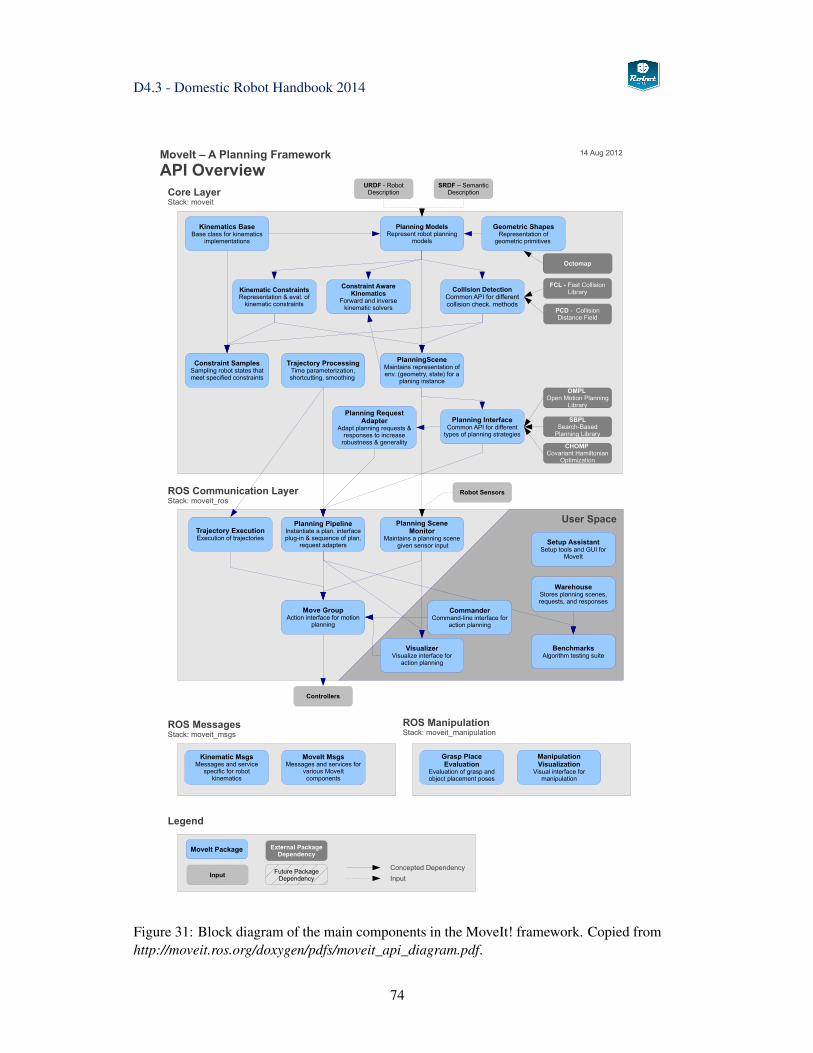
D4.3 - Domestic Robot Handbook 2014
FCL - Fast Collision Library
OMPL Open Motion Planning
Library
Octomap
Core LayerStack: moveit
ROS Communication LayerStack: moveit_ros
Planning PipelineInstantiate a plan. interface plug-in & sequence of plan.
request adapters
Move GroupAction interface for motion
planning
Planning Scene Monitor
Maintains a planning scene given sensor input Setup Assistant
Setup tools and GUI for MoveIt
WarehouseStores planning scenes, requests, and responses
BenchmarksAlgorithm testing suite
MoveIt – A Planning Framework
API Overview
Geometric ShapesRepresentation of
geometric primitives
PlanningSceneMaintains representation of env. (geometry, state) for a
planing instance
Kinematic ConstraintsRepresentation & eval. of
kinematic constraints
Collision DetectionCommon API for different collision check. methods
Planning ModelsRepresent robot planning
models
URDF - Robot Description
PCD - Collision Distance Field
SBPLSearch-Based
Planning Library
CHOMP Covariant Hamiltonian
Optimization
Robot Sensors
VisualizerVisualize interface for
action planning
Constraint SamplesSampling robot states that meet specified constraints
Planning RequestAdapter
Adapt planning requests & responses to increase
robustness & generality
Planning InterfaceCommon API for different
types of planning strategies
Trajectory ExecutionExecution of trajectories
ROS ManipulationStack: moveit_manipulation
ROS MessagesStack: moveit_msgs
Legend
Input
MoveIt Package External Package Dependency
Concepted Dependency
Input
Grasp Place Evaluation
Evaluation of grasp and object placement poses
ManipulationVisualization
Visual interface for manipulation
Kinematic MsgsMessages and service
specific for robot kinematics
MoveIt MsgsMessages and services for
various MoveIt components
Constraint Aware Kinematics
Forward and inverse kinematic solvers
Future Package Dependency
Trajectory ProcessingTime parameterization, shortcutting, smoothing
Kinematics BaseBase class for kinematics
implementations
User Space
Controllers
14 Aug 2012
SRDF – Semantic Description
CommanderCommand-line interface for
action planning
Figure 31: Block diagram of the main components in the MoveIt! framework. Copied fromhttp://moveit.ros.org/doxygen/pdfs/moveit_api_diagram.pdf.
74
D4.3 - Domestic Robot Handbook 2014
For each planning group, MoveIt! expects controllers that offer the FollowJointTrajecto-ryAction actionlib interface. Therefore, a configuration file controllers.yaml needs to becreated which defines the corresponding controllers:
controller_manager_ns: jaco_controller_managercontroller_list:
- name: jaco_arm_controllerns: follow_joint_trajectory
default: truejoints:
- jaco_wrist_roll_joint- jaco_elbow_roll_joint- jaco_elbow_pitch_joint- jaco_shoulder_pitch_joint- jaco_shoulder_yaw_joint- jaco_hand_roll_joint
The required launch file has been auto-generated by the assistant, but in the current softwareversion ends up empty. Edit the file jaco_moveit_controller_manager.launch, where the lastline must be adapted so that the parameter references the configuration file created in thelast step above:
<launch><arg name="moveit_controller_manager"
default="jaco_moveit_controller_manager/MoveItControllerManager" /><param name="moveit_controller_manager"
value="$(arg moveit_controller_manager)"/>
<arg name="controller_manager_name" default="jaco_controller_manager" /><param name="controller_manager_name"
value="$(arg controller_manager_name)" />
<arg name="use_controller_manager" default="true" /><param name="use_controller_manager"
value="$(arg use_controller_manager)" />
<rosparam file="$(find moveit)/config/controllers.yaml"/></launch>
In the current software version, the generated moveit_controller_manager.launch file refer-ences a MoveItControllerManager which is not included in the default ROS installation.
The following example program demonstrates a simple ROS node that subscribes to the/move_group/result topic. Every time that the MoveIt! planner has generated a motion,the chatterCallback function is called with a MoveGroupActionResult object as the param-eter. The code than fills a FllowJointTrajectoryActionGoal object and publishes this onthe Jaco follow_joint_trajectory/goal topic, which starts the corresponding Jaco joint-leveltrajectory:
75
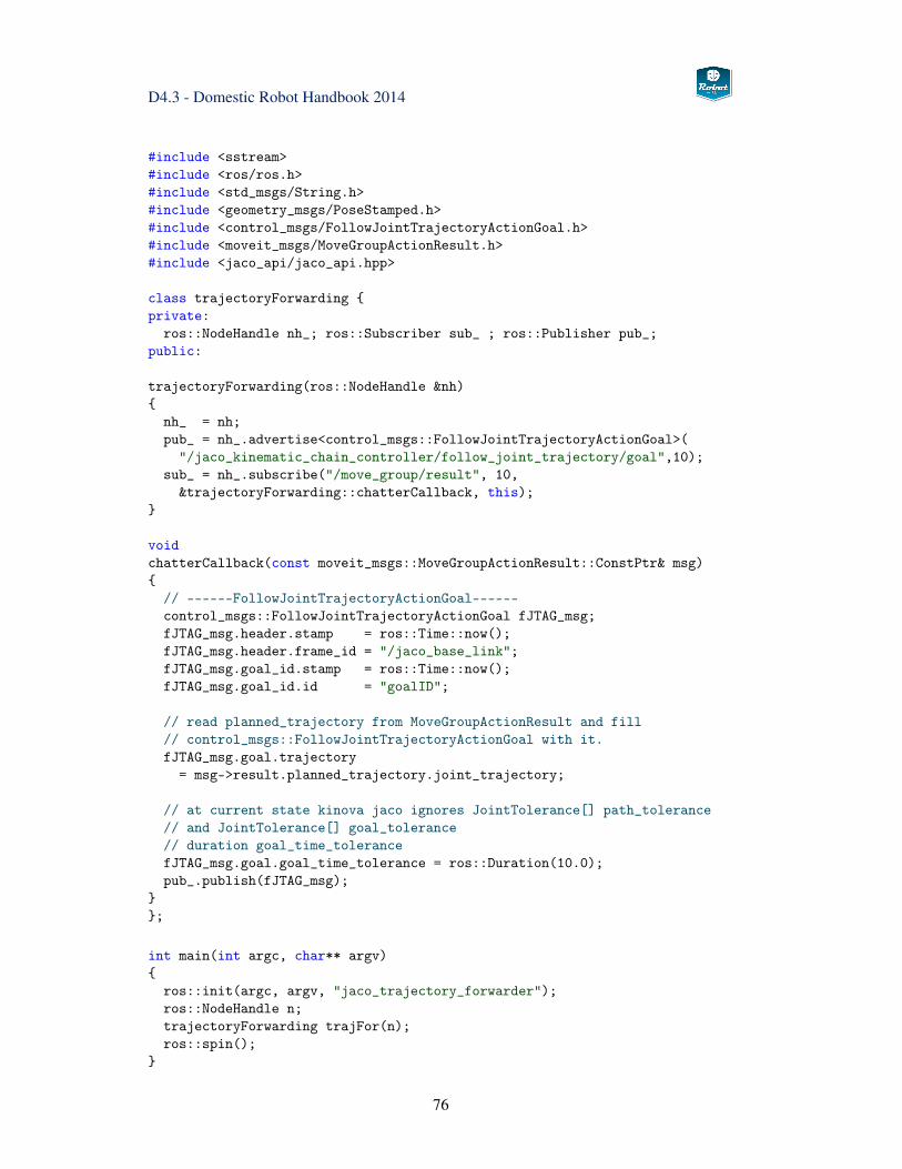
D4.3 - Domestic Robot Handbook 2014
#include <sstream>#include <ros/ros.h>#include <std_msgs/String.h>#include <geometry_msgs/PoseStamped.h>#include <control_msgs/FollowJointTrajectoryActionGoal.h>#include <moveit_msgs/MoveGroupActionResult.h>#include <jaco_api/jaco_api.hpp>
class trajectoryForwarding {private:
ros::NodeHandle nh_; ros::Subscriber sub_ ; ros::Publisher pub_;public:
trajectoryForwarding(ros::NodeHandle &nh){
nh_ = nh;pub_ = nh_.advertise<control_msgs::FollowJointTrajectoryActionGoal>(
"/jaco_kinematic_chain_controller/follow_joint_trajectory/goal",10);sub_ = nh_.subscribe("/move_group/result", 10,
&trajectoryForwarding::chatterCallback, this);}
voidchatterCallback(const moveit_msgs::MoveGroupActionResult::ConstPtr& msg){
// ------FollowJointTrajectoryActionGoal------control_msgs::FollowJointTrajectoryActionGoal fJTAG_msg;fJTAG_msg.header.stamp = ros::Time::now();fJTAG_msg.header.frame_id = "/jaco_base_link";fJTAG_msg.goal_id.stamp = ros::Time::now();fJTAG_msg.goal_id.id = "goalID";
// read planned_trajectory from MoveGroupActionResult and fill// control_msgs::FollowJointTrajectoryActionGoal with it.fJTAG_msg.goal.trajectory
= msg->result.planned_trajectory.joint_trajectory;
// at current state kinova jaco ignores JointTolerance[] path_tolerance// and JointTolerance[] goal_tolerance// duration goal_time_tolerancefJTAG_msg.goal.goal_time_tolerance = ros::Duration(10.0);pub_.publish(fJTAG_msg);
}};
int main(int argc, char** argv){
ros::init(argc, argv, "jaco_trajectory_forwarder");ros::NodeHandle n;trajectoryForwarding trajFor(n);ros::spin();
}
76
D4.3 - Domestic Robot Handbook 2014
<launch><arg name="planning_plugin" value="ompl_interface_ros/OMPLPlanner" /><arg name="planning_adapters" value="
default_planner_request_adapters/AddTimeParameterizationdefault_planner_request_adapters/FixWorkspaceBoundsdefault_planner_request_adapters/FixStartStateBoundsdefault_planner_request_adapters/FixStartStateCollisiondefault_planner_request_adapters/FixStartStatePathConstraints" />
<param name="planning_plugin" value="$(arg planning_plugin)" /><param name="request_adapters" value="$(arg planning_adapters)" /><param name="start_state_max_bounds_error" value="0.1" />
<rosparam command="load"file="$(find moveitDomestic)/config/kinematics.yaml"/>
<rosparam command="load"file="$(find moveitDomestic)/config/ompl_planning.yaml"/>
</launch>
3.7 Manipulation Action Server
The Manipulation Action Server server provides a ROS node, that is specific to the Domes-tic robot and provides the higher level actions that need to be carried out by the platform. Itrequires both MoveIt and Visionhub to be started on the robot system. Depending on theircomplexity and duration the functions are provided either as ROS servics or as Actionlibservers.
Like the name says, the main purpose of this node is to provide services to grasp or handoverobjects. Thes services are exposed using the ROS Actionlib library and therefore supportcancellation of actions and feedback messages. When a manipulation action is called, thisnodes retrieves a list of possible grasp poses from the Visionhub node and uses ROS Moveitin order to calculate the collision aware trajectory. Object handover to the user is imple-mented featuring force controlled handover procedure. The robot uses its force sensors todetect when the user applies a stable grasp and then releases the object. A simple state ma-chine ensures that only actions can be carried out that currently make sense (e.g. handoveris only possible when an object is grasped).
A "place" service is also implemented, allowing the caller to specify how the currentlygrasped object is treated:
• drop at a defined place (the most simple operation), can also be defined relatively toanother object (e.g. a bin)
• place operation, where the footprint of the currently grasped object is put on top of asurface specified in the call (on top of another object, on the tray of the robot)
• optionally the constraint can be defined to keep the object upright
77
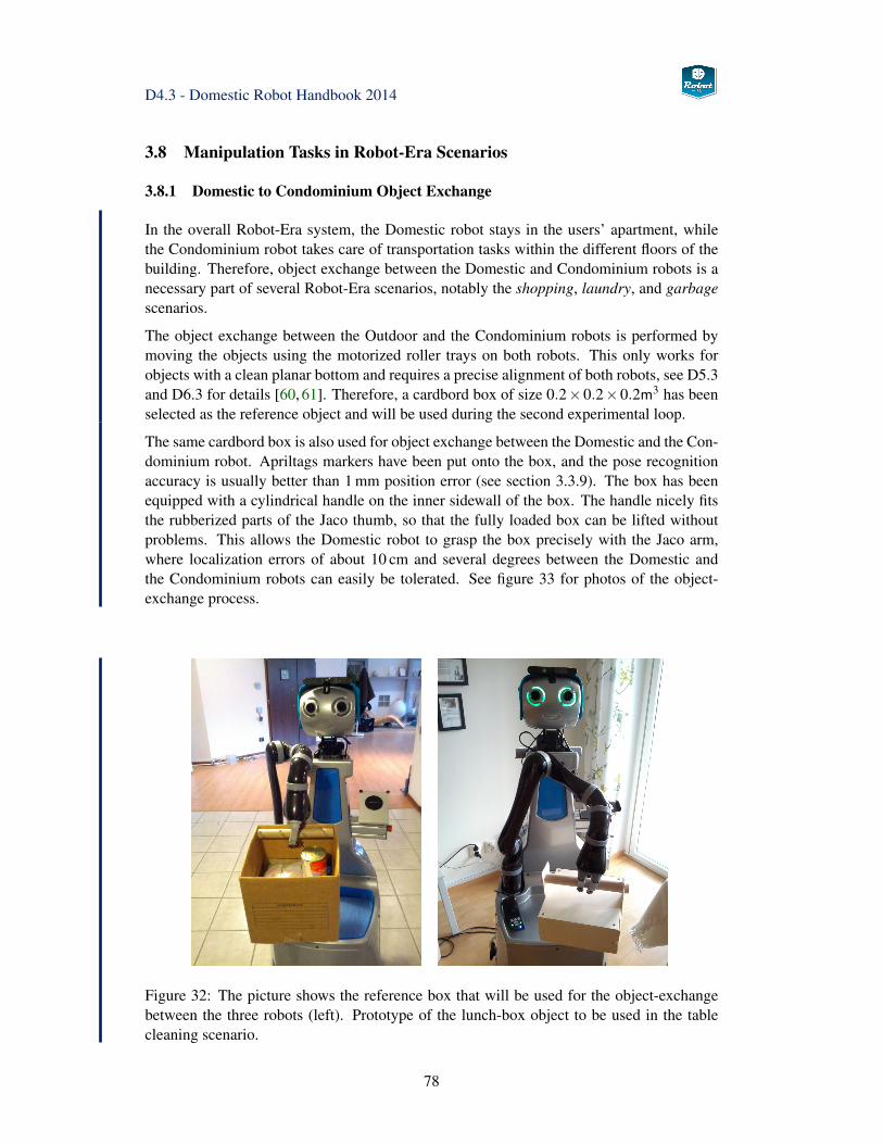
D4.3 - Domestic Robot Handbook 2014
3.8 Manipulation Tasks in Robot-Era Scenarios
3.8.1 Domestic to Condominium Object Exchange
In the overall Robot-Era system, the Domestic robot stays in the users’ apartment, whilethe Condominium robot takes care of transportation tasks within the different floors of thebuilding. Therefore, object exchange between the Domestic and Condominium robots is anecessary part of several Robot-Era scenarios, notably the shopping, laundry, and garbagescenarios.
The object exchange between the Outdoor and the Condominium robots is performed bymoving the objects using the motorized roller trays on both robots. This only works forobjects with a clean planar bottom and requires a precise alignment of both robots, see D5.3and D6.3 for details [60, 61]. Therefore, a cardbord box of size 0.2×0.2×0.2m3 has beenselected as the reference object and will be used during the second experimental loop.
The same cardbord box is also used for object exchange between the Domestic and the Con-dominium robot. Apriltags markers have been put onto the box, and the pose recognitionaccuracy is usually better than 1 mm position error (see section 3.3.9). The box has beenequipped with a cylindrical handle on the inner sidewall of the box. The handle nicely fitsthe rubberized parts of the Jaco thumb, so that the fully loaded box can be lifted withoutproblems. This allows the Domestic robot to grasp the box precisely with the Jaco arm,where localization errors of about 10 cm and several degrees between the Domestic andthe Condominium robots can easily be tolerated. See figure 33 for photos of the object-exchange process.
Figure 32: The picture shows the reference box that will be used for the object-exchangebetween the three robots (left). Prototype of the lunch-box object to be used in the tablecleaning scenario.
78
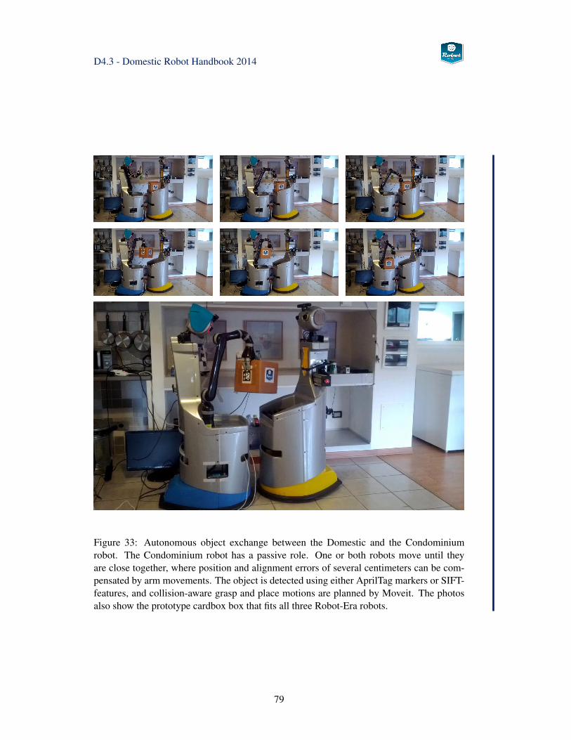
D4.3 - Domestic Robot Handbook 2014
Figure 33: Autonomous object exchange between the Domestic and the Condominiumrobot. The Condominium robot has a passive role. One or both robots move until theyare close together, where position and alignment errors of several centimeters can be com-pensated by arm movements. The object is detected using either AprilTag markers or SIFT-features, and collision-aware grasp and place motions are planned by Moveit. The photosalso show the prototype cardbox box that fits all three Robot-Era robots.
79
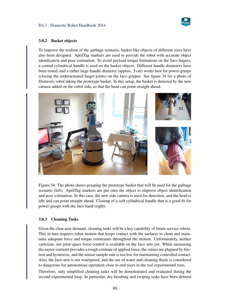
D4.3 - Domestic Robot Handbook 2014
3.8.2 Basket objects
To improve the realism of the garbage scenario, basket-like objects of different sizes havealso been designed. AprilTag markers are used to provide the robot with accurate objectidentfication and pose estimation. To avoid payload torque limitations on the Jaco fingers,a central cylindrical handle is used on the basket objects. Different handle diameters havebeen tested, and a rather large handle diameter (approx. 5 cm) works best for power-grasps(closing the underactuated finger-joints) on the Jaco gripper. See figure 34 for a photo ofDomestic robot taking the prototype basket. In this setup, the basket is detected by the newcamera added on the robot side, so that the head can point straight ahead.
Figure 34: The photo shows grasping the prototype basket that will be used for the garbagescenario (left). AprilTag markers are put onto the object to improve object identificationand pose estimation. In this case, the new side camera is used for detection, and the head isidle and can point straight ahead. Closeup of a soft cylindrical handle that is a good fit forpower-grasps with the Jaco hand (right).
3.8.3 Cleaning Tasks
Given the clear user demand, cleaning tasks will be a key capability of future service robots.This in turn requires robot motion that keeps contact with the surfaces to clean and main-tains adequate force and torque constraints throughout the motion. Unfortunately, neithercartesian- nor joint-space force-control is available on the Jaco arm yet. While measuringthe motor-currents provides a rough estimate of applied force, the values are plagued by fric-tion and hysteresis, and the sensor sample-rate is too low for maintaining controlled contact.Also, the Jaco arm is not waterproof, and the use of water and cleaning fluids is consideredto dangerous for autonomous operation close to end users in the real experimental tests.
Therefore, only simplified cleaning tasks will be demonstrated and evaluated during thesecond experimental loop. In particular, dry brushing and swiping tasks have been defined
80
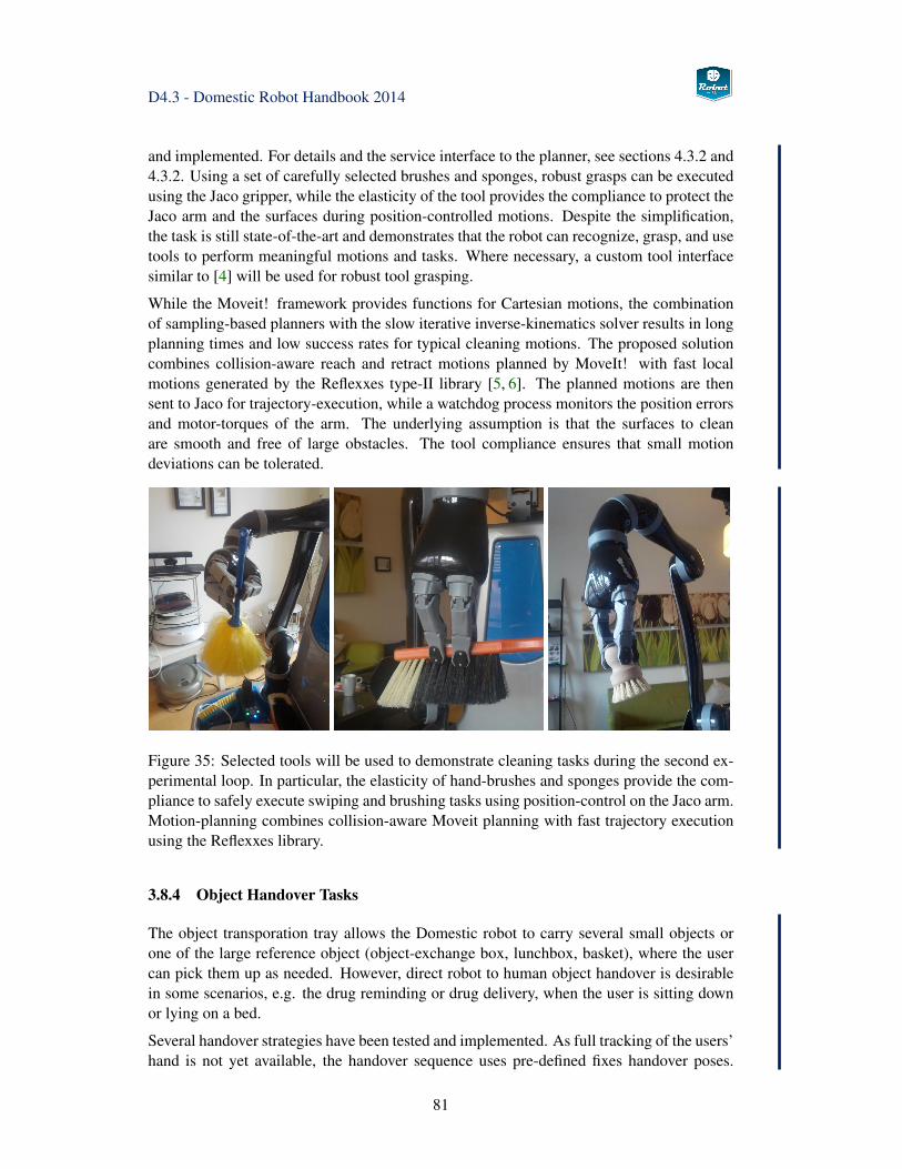
D4.3 - Domestic Robot Handbook 2014
and implemented. For details and the service interface to the planner, see sections 4.3.2 and4.3.2. Using a set of carefully selected brushes and sponges, robust grasps can be executedusing the Jaco gripper, while the elasticity of the tool provides the compliance to protect theJaco arm and the surfaces during position-controlled motions. Despite the simplification,the task is still state-of-the-art and demonstrates that the robot can recognize, grasp, and usetools to perform meaningful motions and tasks. Where necessary, a custom tool interfacesimilar to [4] will be used for robust tool grasping.
While the Moveit! framework provides functions for Cartesian motions, the combinationof sampling-based planners with the slow iterative inverse-kinematics solver results in longplanning times and low success rates for typical cleaning motions. The proposed solutioncombines collision-aware reach and retract motions planned by MoveIt! with fast localmotions generated by the Reflexxes type-II library [5, 6]. The planned motions are thensent to Jaco for trajectory-execution, while a watchdog process monitors the position errorsand motor-torques of the arm. The underlying assumption is that the surfaces to cleanare smooth and free of large obstacles. The tool compliance ensures that small motiondeviations can be tolerated.
Figure 35: Selected tools will be used to demonstrate cleaning tasks during the second ex-perimental loop. In particular, the elasticity of hand-brushes and sponges provide the com-pliance to safely execute swiping and brushing tasks using position-control on the Jaco arm.Motion-planning combines collision-aware Moveit planning with fast trajectory executionusing the Reflexxes library.
3.8.4 Object Handover Tasks
The object transporation tray allows the Domestic robot to carry several small objects orone of the large reference object (object-exchange box, lunchbox, basket), where the usercan pick them up as needed. However, direct robot to human object handover is desirablein some scenarios, e.g. the drug reminding or drug delivery, when the user is sitting downor lying on a bed.
Several handover strategies have been tested and implemented. As full tracking of the users’hand is not yet available, the handover sequence uses pre-defined fixes handover poses.
81
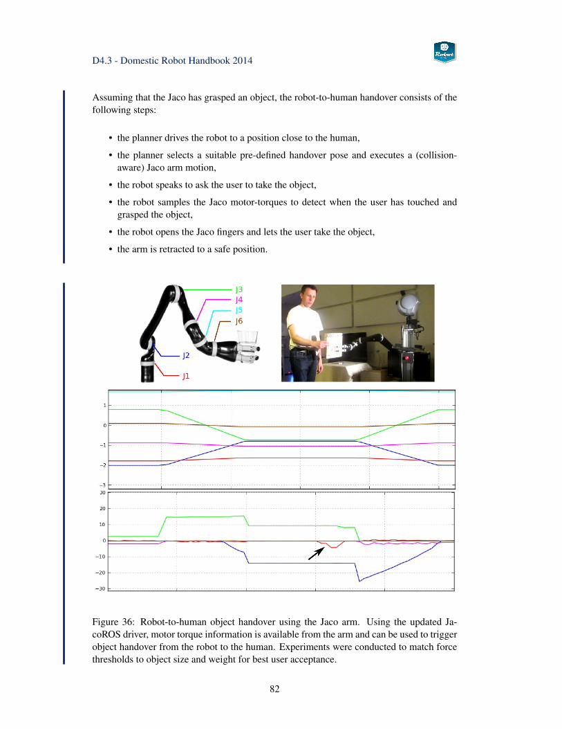
D4.3 - Domestic Robot Handbook 2014
Assuming that the Jaco has grasped an object, the robot-to-human handover consists of thefollowing steps:
• the planner drives the robot to a position close to the human,
• the planner selects a suitable pre-defined handover pose and executes a (collision-aware) Jaco arm motion,
• the robot speaks to ask the user to take the object,
• the robot samples the Jaco motor-torques to detect when the user has touched andgrasped the object,
• the robot opens the Jaco fingers and lets the user take the object,
• the arm is retracted to a safe position.
Figure 36: Robot-to-human object handover using the Jaco arm. Using the updated Ja-coROS driver, motor torque information is available from the arm and can be used to triggerobject handover from the robot to the human. Experiments were conducted to match forcethresholds to object size and weight for best user acceptance.
82
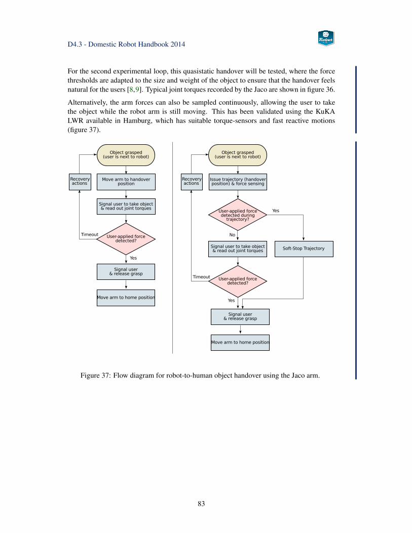
D4.3 - Domestic Robot Handbook 2014
For the second experimental loop, this quasistatic handover will be tested, where the forcethresholds are adapted to the size and weight of the object to ensure that the handover feelsnatural for the users [8,9]. Typical joint torques recorded by the Jaco are shown in figure 36.
Alternatively, the arm forces can also be sampled continuously, allowing the user to takethe object while the robot arm is still moving. This has been validated using the KuKALWR available in Hamburg, which has suitable torque-sensors and fast reactive motions(figure 37).
Figure 37: Flow diagram for robot-to-human object handover using the Jaco arm.
83
D4.3 - Domestic Robot Handbook 2014
3.9 Robot Watchdog
While the hardware of the Domestic robot performed as expected and no component failureoccured during the first experimental loop, several minor problems and a few design issueswere identified in the overall Robot-Era architecture and the robot software. Some failuremechanisms were easy to track down, with flooded Wifi connections to the robots one ofthe obvious causes. When running all Robot-Era components, significant packet loss andlatencies of up to 30 secs have been observed. This triggers message retransmissions, whichin turn worsens the issue, and the long delay often invalidates timestamped ROS messages,making the received data useless for further processing. Better wireless network infrastruc-ture will be installed in AngenLab and Domocasa for the second experimental loop.
The simple problem of an overloaded main robot computer was addressed by installingadditional processors connected by an on-board network. Two Intel NUC modules were se-lected due to good processor speed and their compact size, increasing the available on-boardperformance by about a factor of three. In particular, the very high amount of data streamedby the XtionPro camera is now handled by one of the Intel NUC modules, with a corre-sponding significant reduction in processor load and USB bandwidth on the main Scitos-G5 computer. While the main computer is still heavily loaded due to running MIRA andCognidrive (platform sensors, localization and navigation) as well as running the roscoreROS master process and the JacoROS arm driver, the load is significantly reduced and isexpected to stay below 100%, so that some spare CPU cycles are available when needed.
Regarding the robot software, the situation is more difficult. Given the complexity of thedistributed ROS software running on each of the three robots, and the intentional lack ofsynchronization in the roslaunch tool, it was not always easy for the experimenters to re-cover from failures. For example, a single crashed ROS node will stop sending messages orservice replies expected by other nodes, and small failures can therefore quickly spread tothe whole network of interconnected ROS nodes. Even identifying the source of the prob-lem can be difficult, but once the failed ROS node has been pinpointed, restarting singlenodes may be impossible due to interdependies and parameters set by complex chains ofnested roslaunch-files.
In this situation, a complete shutdown and reboot of the whole robot system was often thequickest solution. Of course, this is inacceptable from a reliability and service-uptime pointof view, and must be avoided for the second experimental loop. Therefore, the roslaunchfiles used for robot bringup have been refactored for better modularity, allowing the operatorto restart parts of the ROS and MIRA/Cognidrive system at runtime.
Work has been started to implement a watchdog program that monitors key components ofthe overall ROS system to help with the detection and analysis of problems and failures. Asimplemented now, the watchdog node simply subscribes to a set of key messages, keepingtrack of timestamps and cross-checking selected message data against expectations. Func-tions and safety checks include:
• periodically querying the roscore master process for the list of running nodes andservices, to check both the health of the roscore process and the status of all requiredROS nodes.
84
D4.3 - Domestic Robot Handbook 2014
• periodically executing a system command (ps -auxwww) via ssh on all three on-boardcomputers to query the Linux kernel for a list of running processes, again checkingstatus of all required ROS nodes and comparing processor load and memory usageagainst a set of (currently hand-coded) thresholds.
• periodically running the iftop command to monitor network load, packet losses, andlatencies.
• subscribing to all sensor messages (front and rear laser-scanners, cameras, XtionPro,gyro, battery, arm) and checking expected data-rate and timestamps on incomingmessages.
• checking battery status.
• reading front and rear laser-scan data and checking for colisions.
• reading PTU data and checking position error to detect possible collisions with envi-ronment and self-collision with the arm.
• reading Jaco data and checking driver status, joint torque estimations, and joint tem-peratures.
• so far, only diagnostic messages are generated, but it would be straightforward to alsorestart nodes automatically or to shutdown the PTU or Jaco driver in case of detectedcollisions.
A list of additional useful watchdog functions has been compiled and will be implementedduring the experimental phase. Also, the processor and network load and the relative im-portance of ROS nodes changes according to the current service performed by the robot,and this should be respected in the analysis. For example, navigation and localization aremost important while the robot platform is driving, while motion planning and arm con-trol are key components during manipulation. As the watchdog already logs process statusand load, this can be correlated with ongoing service requests and will be used to build theexpected activity patterns to be checked in future runs.
85
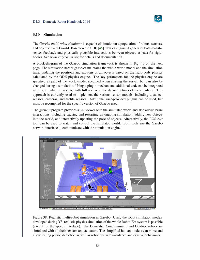
D4.3 - Domestic Robot Handbook 2014
3.10 Simulation
The Gazebo multi-robot simulator is capable of simulation a population of robots, sensors,and objects in a 3D world. Based on the ODE [45] physics engine, it generates both realisticsensor feedback and physically plausible interactions between objects, at least for rigid-bodies. See www.gazebosim.org for details and documentation.
A block-diagram of the Gazebo simulation framework is shown in Fig. 40 on the nextpage. The simulation kernel gzserver maintains the whole world model and the simulationtime, updating the positions and motions of all objects based on the rigid-body physicscalculated by the ODE physics engine. The key parameters for the physics engine arespecified as part of the world-model specified when starting the server, but can also bechanged during a simulation. Using a plugin-mechanism, additional code can be integratedinto the simulation process, with full access to the data-structures of the simulator. Thisapproach is currently used to implement the various sensor models, including distance-sensors, cameras, and tactile sensors. Additional user-provided plugins can be used, butmust be recompiled for the specific version of Gazebo used.
The gzclient program provides a 3D-viewer onto the simulated world and also allows basicinteractions, including pausing and restarting an ongoing simulation, adding new objectsinto the world, and interactively updating the pose of objects. Alternatively, the ROS rviztool can be used to watch and control the simulated world. Both tools use the Gazebonetwork interface to communicate with the simulation engine.
Figure 38: Realistic multi-robot simulation in Gazebo. Using the robot simulation modelsdeveloped during Y3, realistic physics simulation of the whole Robot-Era system is possible(except for the speech interface). The Domestic, Condominium, and Outdoor robots aresimulated with all their sensors and actuators. The simplified human models can move andallow testing person detection as well as robot obstacle avoidance and evasive behaviours.
86
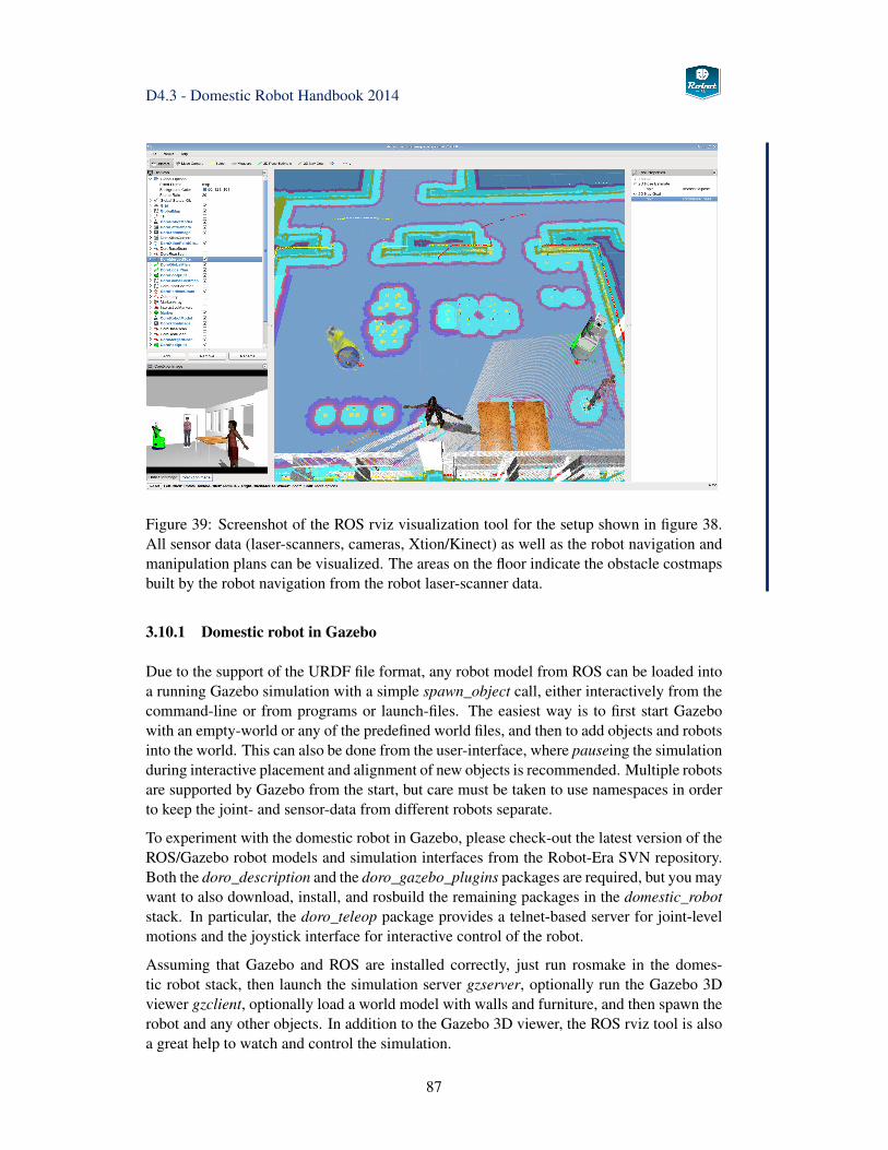
D4.3 - Domestic Robot Handbook 2014
Figure 39: Screenshot of the ROS rviz visualization tool for the setup shown in figure 38.All sensor data (laser-scanners, cameras, Xtion/Kinect) as well as the robot navigation andmanipulation plans can be visualized. The areas on the floor indicate the obstacle costmapsbuilt by the robot navigation from the robot laser-scanner data.
3.10.1 Domestic robot in Gazebo
Due to the support of the URDF file format, any robot model from ROS can be loaded intoa running Gazebo simulation with a simple spawn_object call, either interactively from thecommand-line or from programs or launch-files. The easiest way is to first start Gazebowith an empty-world or any of the predefined world files, and then to add objects and robotsinto the world. This can also be done from the user-interface, where pauseing the simulationduring interactive placement and alignment of new objects is recommended. Multiple robotsare supported by Gazebo from the start, but care must be taken to use namespaces in orderto keep the joint- and sensor-data from different robots separate.
To experiment with the domestic robot in Gazebo, please check-out the latest version of theROS/Gazebo robot models and simulation interfaces from the Robot-Era SVN repository.Both the doro_description and the doro_gazebo_plugins packages are required, but you maywant to also download, install, and rosbuild the remaining packages in the domestic_robotstack. In particular, the doro_teleop package provides a telnet-based server for joint-levelmotions and the joystick interface for interactive control of the robot.
Assuming that Gazebo and ROS are installed correctly, just run rosmake in the domes-tic robot stack, then launch the simulation server gzserver, optionally run the Gazebo 3Dviewer gzclient, optionally load a world model with walls and furniture, and then spawn therobot and any other objects. In addition to the Gazebo 3D viewer, the ROS rviz tool is alsoa great help to watch and control the simulation.
87
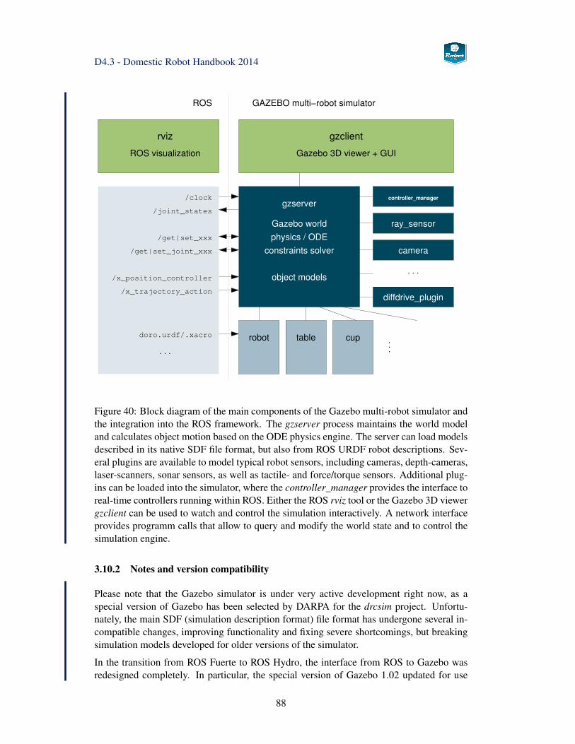
D4.3 - Domestic Robot Handbook 2014
. . .
controller_manager
/x_trajectory_action
/x_position_controller
. . .
doro.urdf/.xacro cuptable
/get|set_joint_xxx
/get|set_xxx
/joint_states
/clock
constraints solver
object models
camera
ROS GAZEBO multi−robot simulator
physics / ODE
Gazebo world
gzserver
ray_sensor
diffdrive_plugin
. . .
Gazebo 3D viewer + GUIROS visualization
gzclientrviz
robot
Figure 40: Block diagram of the main components of the Gazebo multi-robot simulator andthe integration into the ROS framework. The gzserver process maintains the world modeland calculates object motion based on the ODE physics engine. The server can load modelsdescribed in its native SDF file format, but also from ROS URDF robot descriptions. Sev-eral plugins are available to model typical robot sensors, including cameras, depth-cameras,laser-scanners, sonar sensors, as well as tactile- and force/torque sensors. Additional plug-ins can be loaded into the simulator, where the controller_manager provides the interface toreal-time controllers running within ROS. Either the ROS rviz tool or the Gazebo 3D viewergzclient can be used to watch and control the simulation interactively. A network interfaceprovides programm calls that allow to query and modify the world state and to control thesimulation engine.
3.10.2 Notes and version compatibility
Please note that the Gazebo simulator is under very active development right now, as aspecial version of Gazebo has been selected by DARPA for the drcsim project. Unfortu-nately, the main SDF (simulation description format) file format has undergone several in-compatible changes, improving functionality and fixing severe shortcomings, but breakingsimulation models developed for older versions of the simulator.
In the transition from ROS Fuerte to ROS Hydro, the interface from ROS to Gazebo wasredesigned completely. In particular, the special version of Gazebo 1.02 updated for use
88
D4.3 - Domestic Robot Handbook 2014
in ROS was dropped. Instead, ROS interfaces are provided to the standalone installationversions of Gazebo.
At the time of writing, Gazebo 1.9 is the official version for ROS Hydro, and this ver-sion has been used for the development and test of the Robot-Era robot simulations modelsduring 2014. Later versions of Gazebo should work when the corresponding plugins areinstalled, but this has not been tested. All sensors and actuators are modeled on the Do-mestic, Condominium, and Outdoor robots, including the laser-scanners, all cameras, theXtion/Kinect RGB-D sensors, as well as the wheel odometry. The sonar-sensors on theScitos-G5 platform are modelled as well, but are currently not used on either the real robotnor the simulation models. However, as Gazebo does not support sound, neither the mi-crophones nor the speakers for the Robot-Era speech interface are modeled. The updatedversion of Gazebo and the use of updated 3D meshes for all three robot also fixes the bugwith undetected self-collisions, that was documented in D4.2.
Unfortunately, not all race-conditions in simulator startup have been fixed yet. Instead, anew C++ class called doro_coro_gazeb_launcher is provided as part of the doro_utilitiespackage. The launcher serializes the spawning of robot simulation models in the Gazeboworld and takes care to start navigation and manipulation plugins in the correct order. Thelauncher also includes utility functions to populate the simulated world with the simulatedhumans and static simulation objects in either ROS (URDF) or Gazebo (SDF) file format.
The best way to launch the multi-robot simulation is therefore to rely on the provided pre-defined launch files, e.g.
roslaunch doro_utilities Y3_doro_coro_hamburg.launchroslaunch doro_utilities Y3_doro_moveit.launch
89
D4.3 - Domestic Robot Handbook 2014
3.11 PEIS Integration
This section describes the interface between the PEIS ecology layer and the several ROSsoftware components on the Domestic robot. As described above (see Fig. 12 on page 22),the interface layer consists of a set of largely independent modules, each of which providesone specific service from the Robot-Era storyboards. During Y3 of the project, the useof PEIS meta-tuples was suggested to simplify the task of the Robot-Era planner. A shortoverview of the corresponding exekutor class hierarchy is given in section 3.11.6.
3.11.1 PEIS-ROS TupleHandler architecture
The basic idea of the PEIS-ROS interface is very simple. It consists of a set of ROS nodes,called TupleHandlers, which first register themselves with ROS, subscribing and publishingtopics, and announcing their ROS services. Next, every TupleHandler registers itself in thePEIS network with a naming pattern that matches the required tuple-names. Whenever oneof the matching tuples is created or changed, a callback function is called and the TupleHan-dler analyzes the tuple and performs the corresponding action. For upstream informationexchange, the TupleHandler will modify the data field of the relevant tuples, and may alsocreate new tuples.
While a TupleHandler will be called on all tuple-changes matching its tuple-name pattern,most of those changes will be silently ignored. The TupleHandler is only triggered whenthe command=ON change arrives, at which time the corresponding service is started. MostTupleHandlers will wait until this time to access the remaining tuples and read the com-mand parameters. It is expected that the value of all required parameters is valid at thetime of the command=ON changle. Of course, it is also possible to write a TupleHandlerthat updates its internal state (e.g. parameters) on every subscribed tuple-change, but thisrequires the management of internal state and may be more complex than simply deferringreading parameters until the start of the activity.
3.11.2 Using actionlib and feedback functions
The basic ROS services are very useful for fire-and-forget tasks, where a request is submit-ted to the server and the client can wait (and must wait) until the reply arrives. However,this architecture is not suitable for the high-level control of the Domestic robot, becauseseveral services are long-running tasks, and PEIS and the multi-robot planner cannot beblocked until the tasks finishes. Also, it may be necessary to cancel an ongoing action.This is exactly the functionality provided by the ROS actionlib architecture, which providesservice-calls that send period feedback message about their progress until the action hascompleted and the final reply is returned. Also, actionlib services can be canceled. Seewww.ros.org/wiki/actionlib for details and documentation.
Therefore, most PEIS-ROS TupleHandlers will support an actionlib interface to their ser-vices, including defintion of the required ROS messages for the goal, status, feedback, andresult of the action. Technically, the corresponding feedback() and result() callback func-tions need to be implemented in the TupleHandler class. At runtime, the TupleHandler
90
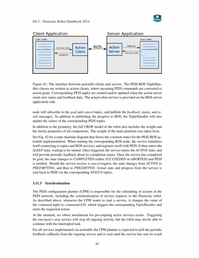
D4.3 - Domestic Robot Handbook 2014
Figure 41: The interface between actionlib clients and servers. The PEIS-ROS TupleHan-dler classes are written as action clients, where incoming PEIS commands are converted toaction goals. Corresponding PEIS tuples are created and/or updated when the action serversends new status and feedback data. The actual robot service is provided on the ROS serverapplication side.
node will subscribe to the goal and cancel topics, and publish the feedback, status, and re-sult messages. In addition to publishing the progress to ROS, the TupleHandler will alsoupdate the values of the corresponding PEIS tuples.
In addition to the geometry, the full URDF model of the robot also includes the weight andthe inertia properties of all components. The weight of the main platform was taken from
See Fig. 42 for a state-machine diagram that shows the common states for the PEIS-ROS ac-tionlib implementation. When starting the corresponding ROS node, the service initializesitself connecting to topics and ROS services, and registers itself with PEIS. It then enters theSLEEP state, waiting to be started. Once triggered, the service enters the ACTIVE state, andwill provide periodic feedback about its completion status. Once the service has completedits goal, the state changes to COMPLETED (either SUCCEEDED or ABORTED) and PEISis notified. Should the service receive a cancel-request, the state changes from ACTIVE toPREEMPTING, and then to PREEMTPED. Actual state and progress from the service issent back to PEIS via the corresponding STATUS-tuples.
3.11.3 Synchronization
The PEIS configuration planner (CPM) is responsible for the scheduling of actions in thePEIS network, including the synchronization of service requests to the Domestic robot.As described above, whenever the CPM wants to start a service, it changes the value ofthe command tuple to command=ON, which triggers the corresponding TupleHandler andstarts the requested action.
At the moment, no robust mechanism for pre-empting active services exists. Triggeringthe emergency-stop service will stop all ongoing activity, but the robot may not be able tocontinue with the interrupted task.
For all services implemented via actionlib, the CPM planner is expected to poll the periodicfeedback callbacks from the ongoing service and to wait until the service has sent its result
91
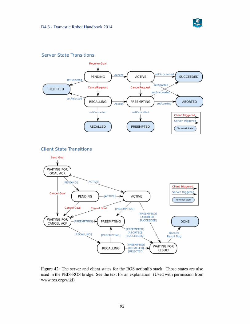
D4.3 - Domestic Robot Handbook 2014
Figure 42: The server and client states for the ROS actionlib stack. Those states are alsoused in the PEIS-ROS bridge. See the text for an explanation. (Used with permission fromwww.ros.org/wiki).
92
D4.3 - Domestic Robot Handbook 2014
message. Sending the cancel request should be acknowledged by the ongoing service, butthe CPM planner still has to wait for the result. A new service can only be requested afterthe previous action has completed. Even short running tasks will be converted to actionlib,so that the high-level interface to the services looks the same from PEIS.
3.11.4 Structured data
In the PEIS framework, the payload of a tuple is supposed to be just an array of bytes.Optionally, the MIME-type and character encoding of the payload can be specified. Helperfunctions are provided to create tuples from null-terminated C-style strings. Unlike ROSand MIRA, the system has no support for multimedia data like JPEG images or complexstructured messages, e.g. Quaternion, JointTrajectory, PointCloud. While such data can bepassed into and transported via PEIS as an opaque array of bytes of the required length, thesystem itself has no notion of the data-type, and application/octet-stream should be used asthe MIME-type. All respective tuple users are therefore responsible to encode and decodethe data themselves.
Within PEIS-ROS, whenever the transport of complex messages is necessary, an additionaltuple will be created with key=*.*.*.ROS_MESSAGE_TYPE and the ROS message classname as the value, e.g. value=geometry_msgs/PoseStamped. A client can first query PEISfor the existence of the ros_message_type tuple, which marks a ROS-based data-type, andthen read the corresponding type from the tuple payload. Next, the client reads the param-eter tuple, and retrieves the binary data. Finally, the client uses the ROS API and helperfunctions to decode the binary data.
Alternatively, some services on the Domestic robot will simply use URLs or URIs (uniqueresource identifiers) as their return values. Strings are handled easily in PEIS and the tuple-view tool, and the client can then use a webbrowser or other tool to retrieve the informationfrom the Domestic robot. See the service descriptions in chapter 4 below for the documen-tation of any URL/URI messages used by the Domestic robot.
3.11.5 Writing a new TupleHandler
The API for writing the TupleHandlers is still not stable, but the main ideas are highlightedin the following short code sequences. The basic idea is to have ROS nodes which also reg-ister themselves with the PEIS ecology. See Fig. 43 for the C/C++ header file that describesthe base class of the TupleHandler/Service hierarchy. The base class contains a reference toa ROS NodeHandle and a PeisSubscriberHandler each. The registerCallback functions arecalled from the init-method and register a user-written callback method for a given tuple keywith PEIS, where the pure virtual getPattern-method returns the tuple pattern (or key) thatis registered with PEIS. For example, robotname.MoveTo.*.COMMAND would ask PEIS tocall the given callback function whenever the value/state of the COMMAND tuple changesin the ecology. A separate init-method is required, as class initializiation in C++ forbids tocall derived methods from a superclass constructor.
The processTuple method is the place where the actual processing of incoming tuples is per-formed. In reaction to a COMMAND=ON change, the service would then read the contents
93
D4.3 - Domestic Robot Handbook 2014
of the corresponding PARAMETERS tuple, parse the given paramenters, and start executionof the corresponding activity.
A very simple example of a derived class is shown in Fig. 44 and 46. Here, the serviceclass inherits from TupleHandler and provides the actual implementation of the getPattern()method as well as the processTutple() method. The main method first calls ros::init andthen the service constructor, which in turn initializes PEIS and the ROS subscriptions andpublisher for the newly created ROS node. The next call to init registers the ROS nodecallback with PEIS, and then enters the endless spin-loop, where the ROS node reacts toincoming PEIS tuples as well as its own ROS subscriptions.
3.11.6 ActionExekutor
While the PEIS-ROS interface described above works fine, the use of hardcoded tuple-names also implies that the overall system is rather inflexible. In particular, restarting aservice requires to reuse and modify existing tuples, with the corresponding need to lockand synchronize tuple access between multiple nodes on the PEIS network.
Therefore, the use of PEIS meta-tuples was suggested by ORU during Y3. A meta-tupleretains the normal key attribute, but the tuple payload is linked at runtime to the valueattribute of another (normal) PEIS tuple. This basically doubles the number of active tupleson the system, but increases flexibility, as the planner or other nodes can dynamically updateand change the payload of existing meta-tuples. This also simplifies online testing of thesystem using the tupleview tool.
To reduce the implementation and re-factoring effort required to introduce meta-tuples, theexekutor class library encapsulates the core functionality of accessing meta-tuples fromROS software. To implement a new service on the robot, a subclass of exekutor is created.When instantiated, the class will automatically create and subscribe to a set of input andoutput meta-tuples with standardized names given to the constructor of the exekutor sub-class. The current setup uses the command and parameters input tuples on every exekutor,while output tuples include the state (idle, running, success, failed), result, and progress(percentage of completion). The exekutor than subscribes to any ROS topics it needs for itstasks. Once activated (by receiving command=ON), the exekutor processes the incomingROS data, calls ROS services and publishes data to ROS as required. To simplify access toactionlib service calls, the action_exekutor base class already provides most of the neces-sary interface code. The concept is very similar to the PEIS-ROS bridge described above.
Please refer to deliverable D3.4 for details about meta-tuples and see section 4 for a list anddocumentation of the different exekutor services implemented for the second experimentalloop of project Robot-Era. See figure 47 for a screenshot of the tupleview tool during a testof the Robot-Era shopping scenario.
94
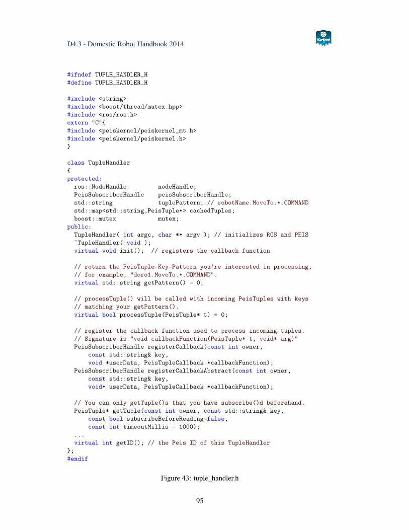
D4.3 - Domestic Robot Handbook 2014
#ifndef TUPLE_HANDLER_H#define TUPLE_HANDLER_H
#include <string>#include <boost/thread/mutex.hpp>#include <ros/ros.h>extern "C"{#include <peiskernel/peiskernel_mt.h>#include <peiskernel/peiskernel.h>}
class TupleHandler{protected:
ros::NodeHandle nodeHandle;PeisSubscriberHandle peisSubscriberHandle;std::string tuplePattern; // robotName.MoveTo.*.COMMANDstd::map<std::string,PeisTuple*> cachedTuples;boost::mutex mutex;
public:TupleHandler( int argc, char ** argv ); // initializes ROS and PEIS~TupleHandler( void );virtual void init(); // registers the callback function
// return the PeisTuple-Key-Pattern you’re interested in processing,// for example, "doro1.MoveTo.*.COMMAND".virtual std::string getPattern() = 0;
// processTuple() will be called with incoming PeisTuples with keys// matching your getPattern().virtual bool processTuple(PeisTuple* t) = 0;
// register the callback function used to process incoming tuples.// Signature is "void callbackFunction(PeisTuple* t, void* arg)"PeisSubscriberHandle registerCallback(const int owner,
const std::string& key,void *userData, PeisTupleCallback *callbackFunction);
PeisSubscriberHandle registerCallbackAbstract(const int owner,const std::string& key,void* userData, PeisTupleCallback *callbackFunction);
// You can only getTuple()s that you have subscribe()d beforehand.PeisTuple* getTuple(const int owner, const std::string& key,
const bool subscribeBeforeReading=false,const int timeoutMillis = 1000);
...virtual int getID(); // the Peis ID of this TupleHandler
};#endif
Figure 43: tuple_handler.h
95
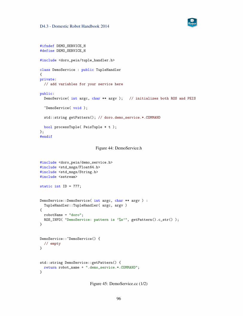
D4.3 - Domestic Robot Handbook 2014
#ifndef DEMO_SERVICE_H#define DEMO_SERVICE_H
#include <doro_peis/tuple_handler.h>
class DemoService : public TupleHandler{private:
// add variables for your service here
public:DemoService( int argc, char ** argv ); // initializes both ROS and PEIS
~DemoService( void );
std::string getPattern(); // doro.demo_service.*.COMMAND
bool processTuple( PeisTuple * t );};#endif
Figure 44: DemoService.h
#include <doro_peis/demo_service.h>#include <std_msgs/Float64.h>#include <std_msgs/String.h>#include <sstream>
static int ID = 777;
DemoService::DemoService( int argc, char ** argv ) :TupleHandler::TupleHandler( argc, argv )
{robotName = "doro";ROS_INFO( "DemoService: pattern is ’%s’", getPattern().c_str() );
}
DemoService::~DemoService() {// empty
}
std::string DemoService::getPattern() {return robot_name + ".demo_service.*.COMMAND";
}
Figure 45: DemoService.cc (1/2)
96
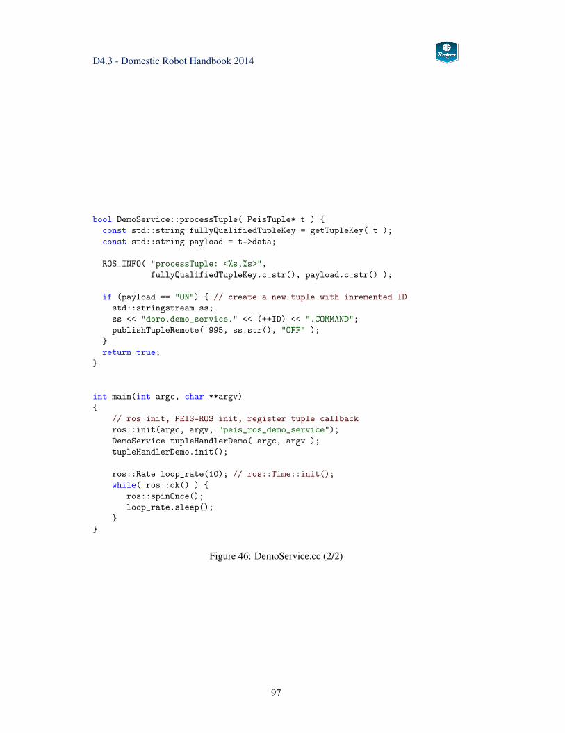
D4.3 - Domestic Robot Handbook 2014
bool DemoService::processTuple( PeisTuple* t ) {const std::string fullyQualifiedTupleKey = getTupleKey( t );const std::string payload = t->data;
ROS_INFO( "processTuple: <%s,%s>",fullyQualifiedTupleKey.c_str(), payload.c_str() );
if (payload == "ON") { // create a new tuple with inremented IDstd::stringstream ss;ss << "doro.demo_service." << (++ID) << ".COMMAND";publishTupleRemote( 995, ss.str(), "OFF" );
}return true;
}
int main(int argc, char **argv){
// ros init, PEIS-ROS init, register tuple callbackros::init(argc, argv, "peis_ros_demo_service");DemoService tupleHandlerDemo( argc, argv );tupleHandlerDemo.init();
ros::Rate loop_rate(10); // ros::Time::init();while( ros::ok() ) {
ros::spinOnce();loop_rate.sleep();
}}
Figure 46: DemoService.cc (2/2)
97
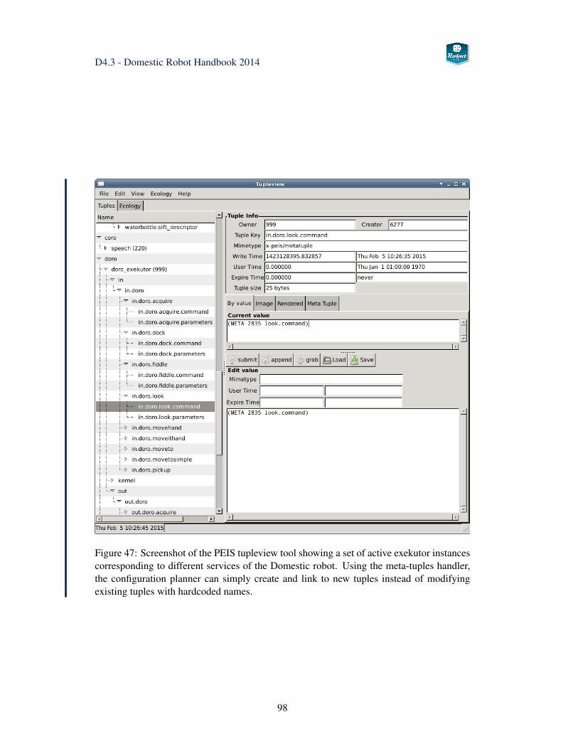
D4.3 - Domestic Robot Handbook 2014
Figure 47: Screenshot of the PEIS tupleview tool showing a set of active exekutor instancescorresponding to different services of the Domestic robot. Using the meta-tuples handler,the configuration planner can simply create and link to new tuples instead of modifyingexisting tuples with hardcoded names.
98
D4.3 - Domestic Robot Handbook 2014
4 Services
This chapter documents the abstract services provided by the Robot-Era domestic robot andspecifies the PEIS tuples used to configure and start the corresponding service. Followingthe project decision to switch the PEIS planning interface to the meta-tuples architecture,most Domestic robot services were updated correspondingly during the end of 2014. There-implementation effort was acceptable, as most of the changes on the PEIS side are en-capsulated in the action_exekutor class. Only small changes were required on our existingROS robot code, because both PEIS-ROS and exekutor interface to ROS via actionlib.
Note that the service descriptions in this handbook are not auto-generated from the actualsource-code, but are simplified a bit to improve readability. Before using any services on thereal robot or in simulation, we recommend to browse and download the latest documentationavailable on the project website www.robot-era.eu, the ROS wiki at www.ros.org/wiki/robot-era, and the Robot-Era software repository.
The robot services are and grouped by function in this handbook. First, subsection 4.1 listsa set of low-level basic skills of the robot, giving access to sensor data or triggering simplemotions. Typically, each PEIS service in this group corresponds to one specific ROS nodeand service, so that the skills can be triggered from either PEIS or ROS.
The next group of services, described in subsection 4.2 on page 115 lists the intermediateskills that can be considered useful building blocks for the construction of typical robottasks, for example, detecting and grasping an object.
The third group of high-level services is sketched in subsection 4.3 on page 133. Theseare the services used in the user-driven scenario descriptions developed within WP2 of theRobot-Era project.
Please refer to the website and software repository for the full list of implemented services,including all parameters and state/feedback options.
99
D4.3 - Domestic Robot Handbook 2014
4.1 Low-Level Services
The services in this group encapsulate the basic skills of the Doro robot, typically targetingonly a single sensor or actuator of the robot. While the services provide the basic sensingand motion infrastructure of the robot, most of the Robot-Era scenarios will not use the low-level services directly. Instead, the scenarios are designed to rely on the intermediate- andhigh-level skills described in subsections 4.2 and 4.3 starting on pages 115 and 133 below.
Of course, the higher-level skills are implemented internally from a suitable set of basicskills triggered in the required sequence. Exposing the low-level services via their individualtuple-handlers provides the Robot-Era system with better flexibility, because the individualskills can also be called by the planner and combined in new ways not implemented byintermediate- or high-level skills. The skills also provide a very useful means for robotsoftware debugging and error-recovery, for example by allowing an expert user to movethe arm around obstacles not handled by the OMPL motion planners, or by rectracting themobile base from a collision.
Note that most of the services described in this section correspond directly to one specificROS service or actionlib service. In addition to being callable via PEIS, all skills can alsobe triggered via ROS messages, and several skills are accessible for interactive use via thesoftware in the doro_teleop package.
During robot startup, one PEIS-ROS or exekutor tuple-handler is created and started for ev-ery low-level service. Each tuple-handler connects to the ROS topics and services requiredfor the particular skill, and then monitors the PEIS network for tuples matching its own pat-tern. Once a tuple with matching key is received, the corresponding data is extracted fromthe value field(s) of the tuples, and stored internally. The skill is triggered as soon as thecommand=ON tuple is received, and executes until completed or until an error condition isdetected. All long-running skills are expected to also provide an actionlib cancel operation,in order to pre-empt the task execution whenever necessary.
For every service, a short overview description is given, followed by the name of the soft-ware modules (tuple-handlers) implementing the service and the specification of the PEIStuples defined to trigger the service and to monitor its execution progress. Where applicable,the implementation status of the service is also described.
100
D4.3 - Domestic Robot Handbook 2014
4.1.1 EmergencyStop
Synopsis This service requests an emergency-stop of the Doro robot. The SCITOS-G5mobile platform is stopped immediately, while the laser-scanners and sonars (when enabled)are kept running for obstacle monitoring and localization. The service is activated by pub-lishing to the request_emergency_stop topic, or by pushing the emergency-stop switch onthe robot.
Any ongoing movements of the PTU and manipulator are stopped and the brakes of thearm are activated. As the Kinova Jaco arm has no hardware brakes, any ongoing motion isinstead canceled and the current robot position is sent as the new setpoint. The arm is keptpowered, because a switch-off results in the arm falling down and potentially harming theuser and equipment.
To restart the robot, a message must be published to the reset_emergency_stop topic.
Handler doro_peis/emergency_stop_handler.cpp
Tuplesin.doro.emergency_stop.command= OFF ‖ ONin.doro.emergency_stop.parameters= noneout.doro.emergency_stop.state= IDLE | ACTIVEout.doro.emergency_stop.result= unusedout.doro.emergency_stop.progress= unused
Status Implemented and tested.
101
D4.3 - Domestic Robot Handbook 2014
4.1.2 GetCameraImage
Synopsis Requests to return the current image from one of the cameras on the robotsensor-head. This service bypasses the PEIS layer, because PEIS lacks support for struc-tured image data and the Robot-Era planner currently does not use or process image data atall.
Instead, a client can directly request either single images or a MJPEG-encoded image streamfrom the mjpeg_server2 running on the robotqn using standard http requests. This way,the images can also be shown on the table graphical user interface, e.g. to displaa the robotcamera image of a unknown person in the surveillance scenario.
The mjpeg-server node is started at robot start-up time and keeps running continuously.However, images are only processed and published when a client requests an image orimage-stream.
Handler mjpeg_server2The service uses http or https requests directly instead of PEIS encapsulation. The servicecan also be run on the Condominium robot.
Tupleshttp://doro:8080/embeddedstream?topic=/left_camera/image_raw?width=320?height=240?quality=40Quality can be chosen from 1 (lowest) to 100 (highest).
Examplehttp://doro:8080/embeddedstream?topic=/left_camera/image_raw?width=640
Status Implemented and tested.
102
D4.3 - Domestic Robot Handbook 2014
4.1.3 GetKinectImage
Synopsis Requests to return the current RGB or depth image from the Kinect/XtionProdepth-camera on the robot head. This service bypasses the PEIS layer, because PEIS lackssupport for structured image data and the Robot-Era planner currently does not use or pro-cess image data at all.
Instead, a client can directly request either single images or a MJPEG-encoded image streamfrom the mjpeg_server2 running on the robot. The mjpeg-server node is started at robotstart-up time and keeps running continuously. However, images are only processed andpublished when a client requests an image or image-stream.
The mjpeg_server2 node is started at robot start-up time and keeps running continuously.Images are only processed and published when a client requests an image or image-stream.
Note: When accessing non-RGB data, the server only transmits the raw stream of imagedata. The client is in charge of demultiplexing and decoding the image. Most nodes access-ing depth image data should subscribe directly to the corresponding ROS topic.
Handler mjpeg_server2The service uses http or https requests directly instead of PEIS encapsulation. The servicecan also be run on the Condominium robot.
Tupleshttp://doro:8080/stream?topic=/xtion_camera/depth_registered/image_raw?width=320?height=240?quality=40
Exampledoro:8080/stream?topic=/xtion_camera/depth/image_raw
Status Implemented and tested.
103
D4.3 - Domestic Robot Handbook 2014
4.1.4 GetLaserScan
Synopsis Requests to return the current scan data from either the front (Sick S300) orrear (Hokuyo-URG) laser-scanners. This returns a string (char-stream) representation of theROS sensor_msgs/LaserScan message, including timestamp, reference frame, and an arrayof distances in meters. We also return the minium distance to the nearest obstacle, whichmay be useful to the high-level planner for re-planning when the on-board navigation isstuck and might need a changed high-level plan.
Handler get_laser_scan_exekutor.cpp
Tuplesin.doro.get_laser_scan.parameters = base_scan ‖ base_scan_rearin.doro.get_laser_scan.command= OFF ‖ ONout.doro.get_laser_scan.state= IDLE ‖ RUNNING ‖ COMPLETED ‖ FAILEDout.doro.get_laser_scan.result=
timestamp reference-frame number-of-distances [distance]* min_distanceout.doro.get_laser_scan.progress= completion-percentage ‖ error-description
Status The service is currently not used by the Robot-Era planner or the HRI modules.All ROS-nodes on the robot should simply subscribe to the /base_scan or /base_scan_reartopics directly.
104
D4.3 - Domestic Robot Handbook 2014
4.1.5 GetSonarScan
Synopsis A Requests to return the latest distance data from the ring of 24 sonar sensorson the SCITOS base. Returns an array with 24 float values, each one giving the minimumdistance to an obstacle reportet by the corresponding sonar sensor.
Handler get_sonar_scan_exekutor.cpp
Tuplesin.doro.get_sonar_scan.parameters = base_scan ‖ base_scan_rearin.doro.get_sonar_scan.command= OFF ‖ ONout.doro.get_sonar_scan.state= IDLE ‖ RUNNING ‖ COMPLETED ‖ FAILEDout.doro.get_sonar_scan.result=
timestamp reference-frame number-of-distances [distance]*out.doro.get_sonar_scan.progress= completion-percentage ‖ error-description
Status Not implemented. The project decided to rely on the much more robust andprecise laser-scanner data for navigation and obstacle detection. The sonar-sensors are cur-rently disabled on the robot.
105
D4.3 - Domestic Robot Handbook 2014
4.1.6 MoveTo
Synopsis Requests the robot to drive to a goal position. The position is specified as a 2D-pose (x,y,Φ) consisting of the x and y coordinates (in meters) and an optional yaw-angle (inradians). The orientation and origin of the coordinate system are based on the current /mapsystem of the robot. Optionally, the xy- and yaw-goal-tolerances for the final robot positioncan be specified in the parameter tuple. Otherwise, the ROS param server is queried tospecify the goal tolerances of the driving motion:
• /move_base/TrajectoryPlannerROS/xy_goal_tolerance
• /move_base/TrajectoryPlannerROS/yaw_goal_tolerance
Mira/Cognidrive is used for controlling the SCITOS-G5 platform [43], while the ROS-MIRA bridge software interfaces MIRA to ROS. Robot localization, motion planning andtrajectory replanning to avoid dynamic obstacles are available and are considered stable.See section 3.2.2 for an overview of the ROS-MIRA bridge.
As a motion command will typically take many seconds before the robot has reached thegoal position, the service relies on a ROS actionlib interface. When necessary, an activeMoveTo service can be cancelled. Feedback about the robot position is not published toPEIS, but is easily availabe via the ROS tf topic.
Handler moveto_exekutor.cpp
Handler moveto_simple_exekutor.cpp
Tuplesin.doro.moveto.parameters = x y yaw (xy-tolerance (yaw-tolerance))in.doro.moveto.command= OFF ‖ ONout.doro.moveto.state= IDLE ‖ RUNNING ‖ COMPLETED ‖ FAILEDout.doro.moveto.result= unusedout.doro.moveto.progress= unused
Status Implemented and tested.
106
D4.3 - Domestic Robot Handbook 2014
4.1.7 Dock and Undock
Synopsis Requests a robot motion to dock to a given object, or to retract (undock) fromthe object. The reference pose (x,y,Θ) of the target object is retrieved from the AmI CAMmodule, where Θ specifies the preferred approach/retract direction to and from the object.Coordinates are interpreted relative to the /map system.
The default action is to dock to the object specified as the single parameter in the parametertuple. If undock is specified, this automatically refers to the previous dock-operation andtarget-object, so that no object needs to be specified.
Driving the robot is performed using calls to the move-to-simple exekutor.
Handler dock_exekutor.cpp
Tuplesin.doro.dock.parameters = object-name ‖ undockin.doro.dockmoveto.command= OFF ‖ ONout.doro.dockmoveto.state= IDLE ‖ RUNNING ‖ COMPLETED ‖ FAILEDout.doro.dockmoveto.result= unusedout.doro.dockmoveto.progress= unused
Status Implemented and tested.
107

D4.3 - Domestic Robot Handbook 2014
4.1.8 MovePtu
Synopsis Requests the robot to move the pan-tilt unit and therefore the sensor-head to agiven goal position specified by the pan- and tilt-angles (radians) with respect to either therobot base coordinate system or the world-coordinate system.
With the current mount position of the PTU46 pan-tilt unit and the doro_ptu46 ROS node,the orientation of the camera head is as follows:
• pan,tilt zero: cameras point straight forward
• pan: positive values are left, negative values are to the right. For example, 0.78 means45◦ to the left, −1.57 means 90◦ to the right.
• tilt: positive values are upwards, negative values downwards. For example, 0.5 is 30◦
upwards, 0 is level, −0.5 is 30◦ down, −0.8 is 46◦ down.
Handler move_ptu_exekutor.cpp
Tuples
in.doro.move_ptu.parameters = pan-angle tilt-angle [coordinate-system]in.doro..move_ptu.command= OFF ‖ ONout.doro.move_ptu.state= IDLE ‖ RUNNING ‖ COMPLETED ‖ ERRORout.doro.move_ptu.result= pan-angle tilt-angleout.doro.move_ptu.progress= completion-percentage ‖ error-description
Status Implemented and tested.
108
D4.3 - Domestic Robot Handbook 2014
4.1.9 RetractJacoArm
Synopsis Requests a joint-level motion of the Jaco arm back to its retract (home) position.This service enables the PEIS layer to request moving the arm back to its initial position.This is required because several Kinova API functions can only be called after the arm hasbeen retracted to its home position. Without this service, the robot-planner would not beable to initialize (or re-initialize) the Jaco arm.
Handler peis_ros/RetractJacoTupleHandler.cpp
Tuples
Status Implemented.
109
D4.3 - Domestic Robot Handbook 2014
4.1.10 ParkJacoArm
Synopsis Requests a joint-level motion of the Jaco arm back to its park (safe) position.The Jaco arm lacks brakes on its joints, and the planetary gears have little friction and arenot self-locking. As such, the arm needs to be parked in specific positions in order to avoidthe arm falling down under the effects of gravitiy when the arm is switched off. This serviceenables the PEIS layer to request moving the arm back to a safe parking position.
Handler peis_ros/ParkJacoTupleHandler.cpp
Tuples
Status Implemented.
110
D4.3 - Domestic Robot Handbook 2014
4.1.11 MoveJacoArm
Synopsis Requests a cartesian or joint-level motion of the Jaco arm, using either absolutevalues or values relative to the current hand position.
For cartesian movements, the coordinates are specified as six double values interpreted as(x,y,z) position and (R,P,Y ) Euler angles. If absolute is specified, values are interpretedin respect to the jaco_link_base frame of the arm (arm mount), while relative values arerelative to the current hand position.
For joint-level movements, the target is also specified as six double values. If absolute isspecified, values are interpreted as absolute joint-angles ( j1, j2, j3, j4, j5, j6), while relativespecifies the per-joint offset to the current arm position.
Handler move_hand_exekutor.cpp
Tuplesin.doro.movehand.parameters =
cartesian ‖ jointsabsolute ‖ relativex y z R P Y ‖ j1 j2 j3 j4 j5 j6
in.doro.movehand.command= OFF ‖ ONout.doro.movehand.state= IDLE ‖ RUNNING ‖ COMPLETED ‖ FAILEDout.doro.movehand.result= unused out.doro.movehand.progress= unused
Examplein.doro.movehand.parameters = joints absolute -1.5 0.2 0.3 0.4 3.14 0.6
Status Implemented and tested.
111
D4.3 - Domestic Robot Handbook 2014
4.1.12 MoveJacoCartesian
Synopsis Requests a joint-level motion of the Jaco arm to the given cartesian pose(x,y,z,R,P,Y ). Note that the current implementation takes coordinates with reference tothe Kinova Jaco coordinate system.
Handler move_hand_exekutor.cpp
Tuples See MoveJacoArm.
Status Implemented and tested.
112
D4.3 - Domestic Robot Handbook 2014
4.1.13 MoveitJacoCartesian
Synopsis Requests a collision-aware joint-level motion of the Jaco arm to the given carte-sian pose (x,y,z,qx,qy,qz,qw) (position, quaternion) with respect to the base_link coordi-nate system of the robot. The motion trajectory is planned by MoveIt with default parame-ters for goal position and orientation constraints.
Handler moveit_hand_exekutor.cpp
Tuplesin.doro.plan_and_move_arm.parameters =
x y z qx qy qz qwin.doro.plan_and_move_arm.command= OFF ‖ ONout.doro.plan_and_move_arm.state= IDLE ‖ RUNNING ‖ COMPLETED ‖ FAILEDout.doro.plan_and_move_arm.result= unusedout.doro.plan_and_move_arm.progress= unused
Status Implemented and tested.
113
D4.3 - Domestic Robot Handbook 2014
4.1.14 MoveJacoFingers
Synopsis Requests to move the fingers to the given joint-angles. While Jaco finger mo-tions are fast and usually complete in less than one second, the current implementation stilluses actionlib calls based on the jaco/finger_action interface of the JacoROS arm drivernode.
The actual motion is selected by the open, close, or absolute command keyword in the PEISparameter tuple, where absolute is followed by three numerical values for the target fingerpositions for fingers F1, F2, and F3. The useful range is [−1,+1], where positive valuesindicate closed fingers, 0 is open, and -1 is required sometimes to reset the hand.
Handler fiddle_exekutor
Tuplesin.doro.fiddle.command= OFF | ONin.doro.fiddle.parameters= open ‖ close ‖ absolute f1 f2 f3out.doro.fiddle.state= IDLE | ACTIVEout.doro.fiddle.result= SUCCESS ‖ FAILEDout.doro.fiddle.progress= unused
Status Implemented and tested.
114
D4.3 - Domestic Robot Handbook 2014
4.2 Intermediate Services
According to the teminology introduced above, the Intermediate Services collect multi-modal perception tasks and manipulation actions that form the building blocks to constructmeaningful robot tasks and the actual Robot-Era services.
On the sensing level, the intermediate services encapsulate perception tasks that use infor-mation from more than one sensor or include significant pre-processing. Typical examplesobject detection using markers or the sensor-fusion from point-cloud and image-featuredata.
For manipulation tasks, most grasping actions fall in this category, because coordinatedhand and finger motions must be executed in combination with environemnt perception toavoid collisions.
115
D4.3 - Domestic Robot Handbook 2014
4.2.1 DetectKnownObject
Synopsis Known objects can be detected using one of the following methods.
• SIFT-based object detection
• PCL-based object detection (including SIFT based classification)1
• AprilTag Markers
In this step only the appearance of the object is detected, not the exact grasp points.
Handler get_detected_objects_exekutor
Tuplesin.doro.visionhub_detection.command= OFF | ONin.doro.visionhub_detection.parameters= unusedout.doro.visionhub_detection.state= IDLE | ACTIVEout.doro.visionhub_detection.result= SUCCESS ‖ FAILEDout.doro.visionhub_detection.detections= object_list, comma seperated+
StatusImplemented, final tuple format definition may need to be modified.
1In this case SIFT is only used to classify the defected point cloud by finding the best match in the objectdatabase
116
D4.3 - Domestic Robot Handbook 2014
4.2.2 DetectUnknownObject
Synopsis Unknown objects can be detected using the Xtion sensor and the tabletop-segmentation stack from ROS. Internally, the detection first calculates the position/orienta-tion of a table-top surface and then searches for point-cloud clusters on top of this surface.For each cluster, the bounding-box, predominant color, and centroid are calculated and usedfor object matching against known objects. Otherwise, the bounding-box can be used forapproximate object grasping. Information about detected objects is forwarded to the AmICAM-module.
Handler acquire_exekutor.cpp
Tuplesin.doro.acquire_tabletop.command= OFF | ONin.doro.acquire_tabletop.parameters=
all tolerance ‖ known tolerance ‖ signature id tolerance
CAM_peis_id = 9898CAM_peis_id.object_name.pos.geo.update= estimated-object-position x y zCAM_peis_id.object_name.color.rgb.update= estimated-object-color r g bCAM_peis_id.object_name.boundingbox.update= estimated-object-color r g b
Examplein.doro.acquire_tabletop.parameters= all 0.8in.doro.acquire_tabletop.parameters= signature nespresso-1 0.7
StatusImplemented and tested.
117
D4.3 - Domestic Robot Handbook 2014
4.2.3 GraspAndLiftKnownObject
Synopsis This service implements grasping and lifting a known object, referring to anobject whose properties are known to the system. Object geometry will be based on a smallset of known basic shapes (sphere, cylinder, box) or the full 3D-mesh of the object.
Once triggered, the service will try to move to the given location, try to detect the objectvia image- and depth-image processing, and estimate the object pose. The database is thenqueried for the set of possible grasps, and the constraints- and collision-aware motion plan-ners will try to find a suitable arm trajectory. The trajectory is then executed to grasp theobject, with visual servoing as possible and force-feedback from the Jaco arm to check thegrasp result.
Handler grasp_exekutor
Tuplesin.doro.grasp_exekutor.command= OFF | ONin.doro.grasp_exekutor.parameters= OBJECT_NAME, optional comma seperated listof arguments: top, sideout.doro.grasp_exekutor.state= IDLE | ACTIVEout.doro.grasp_exekutor.result= IDLE ‖ RUNNING ‖ SUCCESS ‖ FAILEDout.doro.grasp_exekutor.progress= unused
StatusImplemented for box-shaped objects, arbitrary shapes are supported when manually defin-ing the grasppoints. Database structure and setup to be decided: reuse household-objectsfrom ROS, or start with something in PEIS?
118
D4.3 - Domestic Robot Handbook 2014
4.2.4 SideGraspAndLiftObject
Synopsis The side grasp service previously defined as a standalone-service is now in-cluded in the grasp_exekutor, where the calling client can restrict the grasps to side-grasps.
Handler grasp_exekutor
Tuplesin.doro.grasp_exekutor.command= OFF | ONin.doro.grasp_exekutor.parameters= OBJECT_NAME, optional comma seperated listof arguments: top, sideout.doro.grasp_exekutor.state= IDLE | ACTIVEout.doro.grasp_exekutor.result= IDLE ‖ RUNNING ‖ SUCCESS ‖ FAILEDout.doro.grasp_exekutor.progress= unused
StatusImplemented.
119
D4.3 - Domestic Robot Handbook 2014
4.2.5 TopGraspAndLiftObject
Synopsis The top grasp service previously defined as a standalone-service is now in-cluded in the grasp_exekutor, where the calling client can restrict the grasps to top-grasps.
Handler grasp_exekutor
Tuplesin.doro.grasp_exekutor.command= OFF | ONin.doro.grasp_exekutor.parameters= OBJECT_NAME, optional list of arguments: top,sideout.doro.grasp_exekutor.state= IDLE | ACTIVEout.doro.grasp_exekutor.result= IDLE ‖ RUNNING ‖ SUCCESS ‖ FAILEDout.doro.grasp_exekutor.progress= unused
Status Implemented.
120
D4.3 - Domestic Robot Handbook 2014
4.2.6 PlaceObjectOnTray
Synopsis After an object has been grasped, place it on the tray of the robot. The caller caneither use one of three predefined positions (leftcenterright) or specify the exact pose of theobject base. The transformation endeffector to object base will be calculated automatically.
Handler place_exekutor
Tuplesin.doro.place_exekutor.command= OFF ‖ ONin.doro.place_exekutor.parameters=
tray,cartesian-place-pose x y z R P Y ‖position leftcenterright
out.doro.place_exekutor.state= IDLE ‖ RUNNING ‖ SUCCESS ‖ FAILEDout.doro.place_exekutor.result= SUCCESS ‖ FAILEDout.doro.place_exekutor.progress= unused
StatusImplemented, theoretically working, final tests necessary before beginning of second exper-imenatation loop.
121

D4.3 - Domestic Robot Handbook 2014
4.2.7 PlaceObject
Synopsis After an object has been grasped, place it on either another object or a carte-sian position. The caller can specify the exact pose of the object base with respect to theposition of another object. The transformation endeffector to object base will be calculatedautomatically.
Handler place_exekutor
Tuplesin.doro.place_exekutor.command= OFF ‖ ONin.doro.place_exekutor.parameters=
object to place currently grasped object on,cartesian-place-pose x y z R P Y
out.doro.place_exekutor.state= IDLE ‖ RUNNING ‖ SUCCESS ‖ FAILEDout.doro.place_exekutor.result= SUCCESS ‖ FAILEDout.doro.place_exekutor.progress= unused
StatusImplemented, theoretically working, final tests necessary before beginning of second exper-imenatation loop.
122
D4.3 - Domestic Robot Handbook 2014
4.2.8 DropObject
Synopsis After an object has been grasped, drop it into another object or a at a cartesianposition. The caller can specify the exact pose of the object base with respect to the po-sition of another object. The transformation endeffector to object base will be calculatedautomatically.
Handler drop_exekutor
Tuplesin.doro.drop_exekutor.command= OFF ‖ ONin.doro.drop_exekutor.parameters=
object to drop currently grasped object into,cartesian-place-pose x y z R P Y
out.doro.drop_exekutor.state= IDLE ‖ RUNNING ‖ SUCCESS ‖ FAILEDout.doro.drop_exekutor.result= SUCCESS ‖ FAILEDout.doro.drop_exekutor.progress= unused
StatusImplemented, theoretically working, final tests necessary before beginning of second exper-imenatation loop.
123
D4.3 - Domestic Robot Handbook 2014
4.2.9 GraspObjectFromTray
Now implemented in the grasp_exekutor, that can store the exact position where the objecthas been placed on the tray by interacting with the Visionhub node. Works similar to theGraspAndLiftKnownObject service, except that the release-position is used to re-grasp theobject, as currently the tray is not visible with the cameras.
Synopsis
Handler grasp_exekutor
Tuplesin.doro.grasp_exekutor.command= OFF | ONin.doro.grasp_exekutor.parameters= OBJECT_NAME, optional comma seperated listof arguments: top, sideout.doro.grasp_exekutor.state= IDLE | ACTIVEout.doro.grasp_exekutor.result= IDLE ‖ RUNNING ‖ SUCCESS ‖ FAILEDout.doro.grasp_exekutor.progress= unused
Status Needs extensive testing.
124
D4.3 - Domestic Robot Handbook 2014
4.2.10 HandoverObjectToUser
Synopsis This service executes an object handover from the Domestic robot to the user,where the actual handover is triggered by the forces applied by the human when taking theobject.
Prerequisite: The robot has grasped an object and is close to the human. Where neces-sary, the find-user service followed by a move-to or move-to-simple should be called by theplanner first. Additionally, the planner should ensure that the grasp pose of the Jaco handis suitable for the given size, shape, and weight of the object and any additional task con-straints. For example, a side grasp might be required for successful handover of a cup filledwith liquid. On the other hand, a grasp pose with two fingers below the object increasesuccess for a heavy object.
The robot now triggers a Jaco arm motion towards the user and stops close to the presumeduser position. The robot than waits until the specified force-threshold is detected on the Jacoarm, which triggers the open-fingers motion to release the object. Optionally, the handoverpose can be specified using either cartesian coordinates (with respect to robot /base_link)or using joint-angles. The force-thresholds to trigger the release motion can be specifiedindividually for each joint of the Jaco arm. See section 3.8.4 and references [8] and [9] fora description of the state-machine and the algorithms used.
Handler handover_exekutor
Tuplesin.doro.handover.command= OFF ‖ ONin.doro.handover.parameters=
empty ‖cartesian-handover-pose x y z R P Y ‖joints-handover-pose j1 j2 j3 j4 j5 j6(force-threshold j1 j2 j3 j4 j5 j6)
out.doro.handover.state= IDLE ‖ RUNNING ‖ SUCCESS ‖ FAILEDout.doro.handover.result= SUCCESS ‖ FAILEDout.doro.handover.progress= unused
Status Implemented and tested.
125
D4.3 - Domestic Robot Handbook 2014
4.2.11 HandoverObjectFromUser
Synopsis This service executes an object handover from the user to the Domestic robot,where the grasping of the object is triggered by the forces applied by the human.
Prerequisite: The robot robot is close to the human and the object presented by the human iswithin reach of the Jaco hand. Where necessary, the find-user service followed by a move-to or move-to-simple should be called by the planner first. Additionally, the planner shouldensure that the grasp pose of the Jaco hand is suitable for the given size, shape, and weightof the object and any additional task constraints.
The robot now triggers a Jaco arm motion towards the user and stops close to the presumedhandover position. The robot than waits until the specified force-threshold is detected onthe Jaco arm, which triggers the close-fingers motion to grasp the object. The handoverpose can be specified using either cartesian coordinates (with respect to robot /base_link)or using joint-angles. The force-thresholds to trigger the release motion can be specifiedindividually for each joint of the Jaco arm.
Handler handover_from_user_exekutor
Tuplesin.doro.handover_from_user.command= OFF ‖ ONin.doro.handover_from_user.parameters=
empty ‖cartesian-handover-pose x y z R P Y ‖joints-handover-pose j1 j2 j3 j4 j5 j6(force-threshold j1 j2 j3 j4 j5 j6)
out.doro.handover_from_user.state= IDLE ‖ RUNNING ‖ SUCCESS ‖ FAILEDout.doro.handover_from_user.result= SUCCESS ‖ FAILEDout.doro.handover_from_user.progress= unused
Status Implemented.
126
D4.3 - Domestic Robot Handbook 2014
4.2.12 PourLiquidMotion
Synopsis This service was documented in the previous version of the robot handbook[58], because a corresponding function is included in the Kinova Jaco API and driver.However, the function relies on user-teleoperation and would be very hard to implementsuccessful using autonomous control. Also, drinking support is not used in any currentRobot-Era scenario.
Handler canceled
Tuples
Status Not used in any Robot-Era scenario for the second experimental loop. Not imple-mented.
127
D4.3 - Domestic Robot Handbook 2014
4.2.13 MoveHingedDoor
Synopsis
Handler peis_ros/MoveDoorTupleHandler.cpp
Tuples
Status Not implemented. Where necessary, automated doors will be used in the secondexperimental loop.
Due to the inadequate implementation of force- and tactile-sensor readout in the Jaco driver,impedance-controlled motions are not possible, and the risk of damage to the Jaco arm orobjects would be very high in position-controlled motions. Implementation will be recon-sidered for robot arms with adequate sensors and software.
128
D4.3 - Domestic Robot Handbook 2014
4.2.14 LookAt
Synopsis This service moves the pan-tilt unit so that the cameras looks at an object knownto the PEIS CAM-module. The CAM in turn returns the corresponding position of the objectas a point (x,y,z) in world coordinates, or optionally any coordinate system known to thetf-transformation library. Unlike the low-level MovePtu-service, this service allows the useror planner to request images (or point-clouds) from a given target location without havingto worry about the current position and orientation of the robot.
Handler look_exekutor.cpp
Tuplesin.doro.look.command= OFF ‖ ONin.doro.look.parameters= object-name (on CAM module)out.doro.look.state= IDLE ‖ RUNNING ‖ SUCCESS ‖ FAILEDout.doro.look.result= SUCCESS ‖ FAILEDout.doro.look.progress= unused
StatusImplemented and tested.
129
D4.3 - Domestic Robot Handbook 2014
4.2.15 DetectPerson
Synopsis This service uses the robot sensors to detect persons near to the robot. Severalsensor modalities and algorithms may be combined, but the actual implementation is notexported to the PEIS layer. When the move-head flag parameter is included, the robot mayuse PTU motions to also detect people not directly in front of the current head positionof the robot. No platform motions are attempted; but the PEIS planner can initiate robotmotions to look for people in different rooms.
The current implementation is based on a pre-trained SVM classifier working on point-cloud data from the Xtion camera. In the first step, a ground-plane estimation step is usedto find clusters in the point cloud, which are then classified according to their size andshape. The ground-plane estimation is initialized from the robot PTU pan- and tilt-angles,and confidence values are calculated for each cluster. Positions of detected persons arecalculated with respect to the given reference frame (usually /map for absolute positions, or/base_link for positions relative to the robot base).
The result tuple contains the number of detected persons in view of the robot (0 . . .n) and onetuple consisting of the estimated (x,y,z) position of one person together with a confidencelevel (float) for that person. Work is underway to also estimate the relative motion of theperson (direction and velocity) with respect to the robot. Progress info is not published,because the service completes when a person is detected of after 10 seconds runtime.
Handler find_user_exekutor.cpp
Tuplesin.doro.find_user.command= OFF ‖ ONin.doro.find_user.parameters = (move-head)
svm ‖ openni (‖ face-detector‖ leg-detector) x y zout.doro.find_user.result= n (x y z)*nout.doro.find_user.state= IDLE ‖ RUNNING ‖ COMPLETED ‖ FAILEDout.doro.find_user.progress= unused
Examplein.doro.find_user.parameters= svm 3 1 1.8out.doro.find_user.result= 0out.doro.find_user.result= 1 3.14 0.71 1.83 0.84out.doro.find_user.result= 2 3.14 0.70 1.79 0.66 2.80 -1.6 1.59 0.33
StatusImplemented and tested using the SVM clustering classifier.
130
D4.3 - Domestic Robot Handbook 2014
4.2.16 TrackPerson
Synopsis This service uses the robot sensors to detect and track persons near to the robot.Several sensor modalities and algorithms may be combined, but the actual implementationis not exported to the PEIS layer. The input (x,y,z) parameters of the service specify whichone of multiple users to track.
Using PTU motion commands, the head of the robot rotates so as to keep the robot lookingstraight at the user. If no user is detected or the user is lost, the service returns failed.Otherwise the service continues until canceled by the planner. The current runtime is sentback to the planner using the progress tuple.
Handler track_user_exekutor.cpp
Tuplesin.doro.track_user.command= OFF ‖ ONin.doro.track_user.parameters =
svm ‖ openni ‖ face-detector‖ leg-detector x y zout.doro.track_user.result= noneout.doro.track_user.state= IDLE ‖ RUNNING ‖ COMPLETED ‖ FAILEDout.doro.track_user.progress= runtime-in-seconds
Examplein.doro.track_user.parameters= svm 3 1 1.8
StatusPrototype implemented (NiTE2 tracker). Needs to be updated for the SVM-cluster detector.
131
D4.3 - Domestic Robot Handbook 2014
4.2.17 RecognizePerson
Synopsis Use the robot sensors to recognize a person near to the robot. The currentimplementation is based on the Eigenfaces algorithm [23], and requires the correspondingset of pre-processed images for each of the known persons. The recognition result is eitherthe name/index of a known person, together with the estimate of the recognition probability,NOT-RECOGNIZED to indicate that an unknown person was detected, or NO-PERSON toindicate that no person could be detected in the current robot sensor data.
Handler peis_ros/RecognizePersonTupleHandler.cpp
Tuplesin.doro.recognize_person.command= OFF ‖ ONin.doro.recognize_person.parameters =
empty ‖ camera-name region-of-interest: xl yt xr ybdoro.recognize_person.state= IDLE ‖ RUNNING ‖ COMPLETED ‖ FAILEDdoro.recognize_person.result=
known-person-name‖ unknown-person‖ no-person-detecteddoro.recognize_person.progress= unused
StatusPrototype implemented (Eigenfaces algorithm). Not yet integrated or tested, as automaticdetection of persons has legal consequences that have to be clarified before use during theexperimental loop.
132
D4.3 - Domestic Robot Handbook 2014
4.3 High-level Services
While the low-level and intermediate robot skills described in the previous sections arevaluable building blocks for the robot programmer, those skills are certainly not useful forthe typical end-user. Instead, the scenario storyboards developed by Robot-Era from theuser studies and questionnaires refer to much more complex actions like clean the dinnertable. This also includes the benchmark task of all service robots, bring me a cup of coffee,where the robot has to identify the user, find the users’ preferred cup, prepare coffee, carrythe full cup without spilling the liquid, and finally hand-over the cup to the user.
The high-level robot services listed in this section directly correspond to the activities re-quested by the users and documented in the project storyboards. All of the services requiresignificant robot autonomy and include complex action sequences, including detection andidentification of objects in cluttered enviroments, skilled manipulation and transport of ob-jects, and interaction with the user(s). Some of the requested tasks are clearly beyond thecurrent state of the art, and only experience will tell whether the domestic robot with theJaco arm is capable of the tasks at all. For example, the clean the window service involvesthe handling and manipulation of tools, possibly even the grasping of a wet soft spoon, andvery difficult perception tasks involving transparent and mirroring objects. Due to the high-level nature of the services, the command interface from PEIS is very simple. The AmIjust prepares the required parameters (“bathroom window”) and triggers the correspondingrobot service.
In order to keep a clean implementation structure and to be able to switch between tasksin a reliable way, many of the high level services are composed by the planner by callingseveral middle level services consecutively. This way it is more convenient to implementerror handling or cancelation of tasks.
However, given the large number of intermediate and low-level skills required to execute theservice, a lot of things can go wrong and execution-monitoring and error recovery becomevery important aspects of the implementation. Whenever the robot cannot execute the activepart of the overall action plan, the service will be canceled and the error reported to PEIS.The AmI planner is then responsible to handle the error, and to attempt a recovery, forexample by requesting the user to point-and-click on the target object in a camera image ofthe robot when the image processing algorithms fail to identify the object.
133
D4.3 - Domestic Robot Handbook 2014
4.3.1 WalkingSupport
Synopsis This service requests walking support for the user. The robot first moves tothe given initial position, tries to detect and recognize the user, and rotates so that the usercan easily reach grasp the handle. The robot then slowly moves to the target position, withcareful execution monitoring to ensure that the users keeps up with the robot and maintainsa stable grasp on the handle.
The service has been split into an autonomous platform motion towards the user, followedby interactive drive control of the robot by the user using the switches in the tilting handle.
Handler moveto_exekutor
Tuples None.
Status To provide a better user experience, this service has been replaced by the directtele-operation of the Domestic robot. Using the switches in the tilting handle, the usercan directly control and drive the robot. Note that the tele-operation software monitors thelaser-scanners to detect and prevent imminent collisions with obstacles in front of the robot.
134
D4.3 - Domestic Robot Handbook 2014
4.3.2 SwipeSurfaceService
Synopsis This service provides a simplified prototype version of indoor cleaning tasksthat is matched to the hardware capabilities of the Kinova Jaco arm and the Moveit motionplanning.
The tasks uses a set of pre-defined tools (sponges and brushes) that have been selectedor have been modified to be graspable by the Jaco hand. Due to lack of force-control onthe arm, tool compliance is used to protect the arm and objects during position-controlledmotions. Also, only selected objects will be available for cleaning (e.g. rectangular regionson tables, windows, and kitchen surfaces), so that location and surface properties can bemodeled in the AmI layer (CAM module).
The actual cleaning tasks will consist of task-aware swiping motions which demonstraterealistic and coordinated arm and tool motions. No water or cleaning liquids will be used,to reduce the risk of accidents with damage to the robot or furniture. This obviously limitsthe efficiency and results of the cleaning, but it is expected that the users will understandthe reasons and rate user acceptance as if the task were executed with liquids.
The elasticity properties of the tools and suitable motion plans (swiping left-to-right andright-to-left, swiping alternating with free-space return motions, circular motions, handlingof corners) will be encapsulated in the swiping service and are not exposed or exported tothe AmI/CAM or planning layer. Where necessary, AprilTag markers will be placed on orclose to the target surface, in order to guarantee the position accuracy required by successfultask execution.
For the full cleaning scneario, the following action sequence is executed by the planner,AmI/CAM, and Domestic robot:
1. user requests the cleaning tasks via speech or GUI,
2. user also selects the room+object to be cleaned,
3. the planner queries the CAM for the appropriate tool and its current location,
4. the planner generates the moveto, look and acquire, and pick-object commands forDoro to locate and grasp the tool,
5. the planner generates the moveto command to drive the robot to a position in front ofthe target surface,
6. the planner generates the parameters for the swipe-surface command, including thetool-name, surface-name, the four corners or the region-of-interest to be cleaned, andoptionally the exit-position where the swiping motions should converge to,
7. Doro generates motion plans for the given tasks and executes them autonomously.Progress feedback is periodically sent back to the planner and user interface,
8. Doro retracts the arm into the home position and indicates SUCCESS or FAILED,
9. the planner generates commands to place the tool and informs the CAM about thenew location.
135
D4.3 - Domestic Robot Handbook 2014
Handler swipe_surface_exekutor.cpp
Tuplesin.doro.swipe_surface.command= OFF ‖ ONin.doro.swipe_surface.parameters =
tool-name surface-namecorner1: (x,y,z) corner2: (x,y,z) corner3: (x,y,z) corner4: (x,y,z)exit-position: (x,y,z)
out.doro.swipe_surface.result= unusedout.doro.swipe_surface.state= IDLE ‖ RUNNING ‖ COMPLETED ‖ FAILEDout.doro.swipe_surface.progress= percentage-of-completion ‖ -1 (FAILED)
Examplein.doro.swipe_surface.parameters =
brush-1 kitchen-table 2 2 0.72 2.5 2 0.72 2.5 2.3 0.72 2 2.3 0.72in.doro.swipe_surface.parameters =
sponge-3 floor 0.1 0.1 0 0.5 0.1 0.01 0.1 0.5 0.01 0.5 0.5 0.02 0.1 0.1 0
Status Prototype implemented; needs testing. The service will be tested during the sec-ond experimental loop.
136
D4.3 - Domestic Robot Handbook 2014
4.3.3 CleanFloorService
Synopsis Based on analysis of the user studies, the clean floor service consists of twodifferent tasks, namely picking up objects lying around on the floor, but also sweeping thefloor. This service was included as a placeholder in the first version of the Domestic robothandbook, D4.2 [58].
For the second experimental loop, the service will be performed in two steps by calling thecorresponding individual services. The grasp-object service will be used to for searchingand the picking-up of objects on the floor, while the swipe-surface service is used for floorsweeping. The following limitations apply:
• realistic use of a full-size broom is not possible due to torque limits on the hand andfingers of the Jaco arm. Smaller brushes or a broom with shorter handle will be used,limiting the sweeping workspace to a region on the right side of the Domestic robot.
• due to occlusion, the areas directly in front and to the right of the robot cannot beobserved by the XtionPro sensor and the cameras on the sensor head. Therefore, theside camera will be used for object/obstacle detection and grasping/sweeping will beperformed on the right of the robot.
• Alternatively, perception of objects on the floor must be performed while the robot isstill about 1 m away from the objects, followed by a platform movements, followedby (blind) grasping.
Handlergrasp_exekutor, swipe_surface_exekutor
TuplesPlease refer to the corresponding services.
StatusThe necessary services are implemented and tested.
137
D4.3 - Domestic Robot Handbook 2014
4.3.4 CleanWindowService
Synopsis Requests the robot to clean the specified window. As originally specified, therobot is expected to remove any obstacles in front of the window, to prepare a bucket withwater and detergent, put the bucket onto the tray, grasp a sponge, move to the window,perform cleaning motions, bring the dirty water to the kitchen, clean bucket and sponge,and finally restore any removed objects back to their original places.
Unfortunately, the complexity remains beyond the state-of-the-art of service robotics ingeneral and the capabilities of the Domestic robot hardware in particular. Therefore, onlya simplified version will be demonstrated during the second experimental loop, where therobot performs cleaning motions using a sponge. This can be performed by a correspondingparametrization of the swipe-surface service with the sponge specified as the tool object andthe coordinates of the window selected by the planner.
Handler swipe_surface_exekutor
Examplein.doro.swipe_surface.parameters =
sponge-2 window-1 2.0 3.0 1.0 2.0 3.5 1.0 2.0 3.5 1.5 2.0 3.0 1.5 2.0 3.25 1.0
Status Prototype implemented; needs testing.
138
D4.3 - Domestic Robot Handbook 2014
4.3.5 CleanTableService
Synopsis As originally specified, the robot moves to the given table, looks for known andunknown objects, grasps the objects and places them on the transportation tray, drives to thekitchen, and puts the objects from the tray to the kitchen sink or the dishwasher. The robotthen returns to the table with a wet sponge or cloth, and swipes the table clean. Optionally,the table is laid again.
The project decided that this service cannot be executed atomically by the robot alone.Instead, the driving motions, object detection, pick and place, and the cleaning are com-manded by the planner in combination with the Ami CAM-module. The integrated serviceis thereby replaced by the corresponding lower-level services.
Handlermoveto_exekutor, dock_exekutor,look_exekutor, acquire_exekutor,moveit_hand_exekutor, grasp_exekutor, place_exekutor,swipe_surface_exekutur.
TuplesSee the corresponding individual services.
Status This service is beyond the state-of-the-art of service robotics (considering un-known objects are placed on arbitrary positions), and will be very difficult to execute withthe current Doro hardware setup. A simplified version of the service using known objectsis expected to be tested as part of the second experimental loop.
139
D4.3 - Domestic Robot Handbook 2014
4.3.6 BringFoodService
Synopsis The BringFoodService is expected to be tested in the second experimental loop.A special box featuring a handle and an optical marker has been designed, that can behanded over from the tray of the Condominium robot to the Domestic robot, that will fetchthis box from the apartment door and place it on the table. This service calls the dockingexecutor, the grasp_exekutor and the place executor. In a planned extension of this scenario,the robot detects (find_user_exekutor) that the user is in front of the robot, and instead ofplacing the object on the table it directly starts the handover procedure (handover_exekutor).
Handlergrasp_exekutor, place_exekutor, docking_exektutor,find_user_exekutor, handover_exekutor
TuplesPlease refer to the corresponding low- and intermediate-level services.
StatusThe necessary low and intermediate level services are implemented and tested. Objecthandover has been tested during the M38 integration week and works reliably.
140
D4.3 - Domestic Robot Handbook 2014
4.3.7 CarryOutGarbage
Synopsis The CarryOutGarbage is expected to be tested in the second experimental loop.A special bucket featuring a handle and an optical marker has been designed, that can begrasped by the Domestic robot and handed over to the Condominium robot. The garbagebin is placed on a defined location in the room. The planner drives the robot to a location,where the marker of the bucket can be detected, then the grasp-service will be called whichcalculates a grasp that can be executed. When the bin is grasped, the Domestic robot docksto the Condominium robot and calls the place_exekutor in order to put the bin on the trayof Coro.
Handlergrasp_exekutor, place_exekutor, docking_exektutor
TuplesPlease refer to the corresponding low- and intermediate-level services.
StatusThe necessary low and intermediate level services are implemented and tested.
141
D4.3 - Domestic Robot Handbook 2014
4.3.8 LaundryService
Synopsis The LaundryService is expected to be tested in the second experimental loop. Aspecial box featuring a handle and an optical marker has been designed, that can be graspedby the domestic robot and handed over to the condominium robot. The procedure and thehandlers correspond directly to that of the CarryOutGarbage-scenario.
Handlergrasp_exekutor, place_exekutor, docking_exektutor
TuplesPlease refer to the corresponding low- and intermediate-level services.
StatusThe necessary low and intermediate level services are implemented and tested.
142

D4.3 - Domestic Robot Handbook 2014
5 Software installation and setup
This chapter summarizes installation, setup, and configuration instructions for the differentmain software packages required for the domestic robot.
5.1 Ubuntu 12.04 and ROS Hydro
While ROS can be compiled on many Linux platforms, the availability of pre-built packageswith regular updates is best for Ubuntu-based platforms. Therefore, Ubuntu 12.04-LTSwas chosen as the operating system of the Domestic Robot. It needs to be installed onall on-board computers (the main Scitos-G5 computer and the two additional Intel NUCD5250WYK modules).
The original software documented in D4.2 [58] was based on ROS version Fuerte, but threenew releases (Groovy, Hydro, Indigo) have been introduced since then. In particular, arobust version of the MoveIt! framework for collision-aware manipulation is only availablefor ROS version Hydro and later. Other improvements relevant for the Domestic Robotinclude the new catkin build system, a cleaner specification of the URDF robot model, andthe interface to the recent versions of the Gazebo robot simulator. While ROS versions canbe mixed to some extent, it is usually easiest to stay with a single version. As ROS Hydrois still actively developed and includes most of the recent improvements, but can be used onUbuntu 12.04, the decision was taken to switch the Domestic Robot software to the Hydroversion of ROS.
Either version can be started by setting the corresponding binary and library search pathsand the ROS_PACKAGE_PATH environment variables. This is usually done as part of theusers’ setup.bash shell setup files.
PCAN kernel module Note that the PCAN kernel module required by MIRA is not partof the standard Ubuntu Linux kernels. After updating the Linux kernel, you will have torecompile the PCAN kernel module and generate the /dev/pcan32 device file. This isdocumented in the MIRA installation guide.
5.2 Software Installation Paths
The different software packages are installed according to usual Linux (Debian/Fedo-ra/Ubuntu) practice, where large non-standard software packages like ROS and MIRA areinstalled into the /opt path of the filesystem.
Again according to current practice, the user-developed ROS stacks and packages are in-stalled into a local ROS workspace managed by the rosws and rosinstall tools, below theusers’ home directory. So far, most of the software development is carried out using the de-fault demo user account. The default home directory in turn is /home/demo, but this is onlyused for the Kinova-specific post-installation stuff, namely the license files created by theWindows-installer from Kinova. The actual ROS workspace files including the DomesticRobot stack is installed into /localhome/demo/ros_workspace.
143
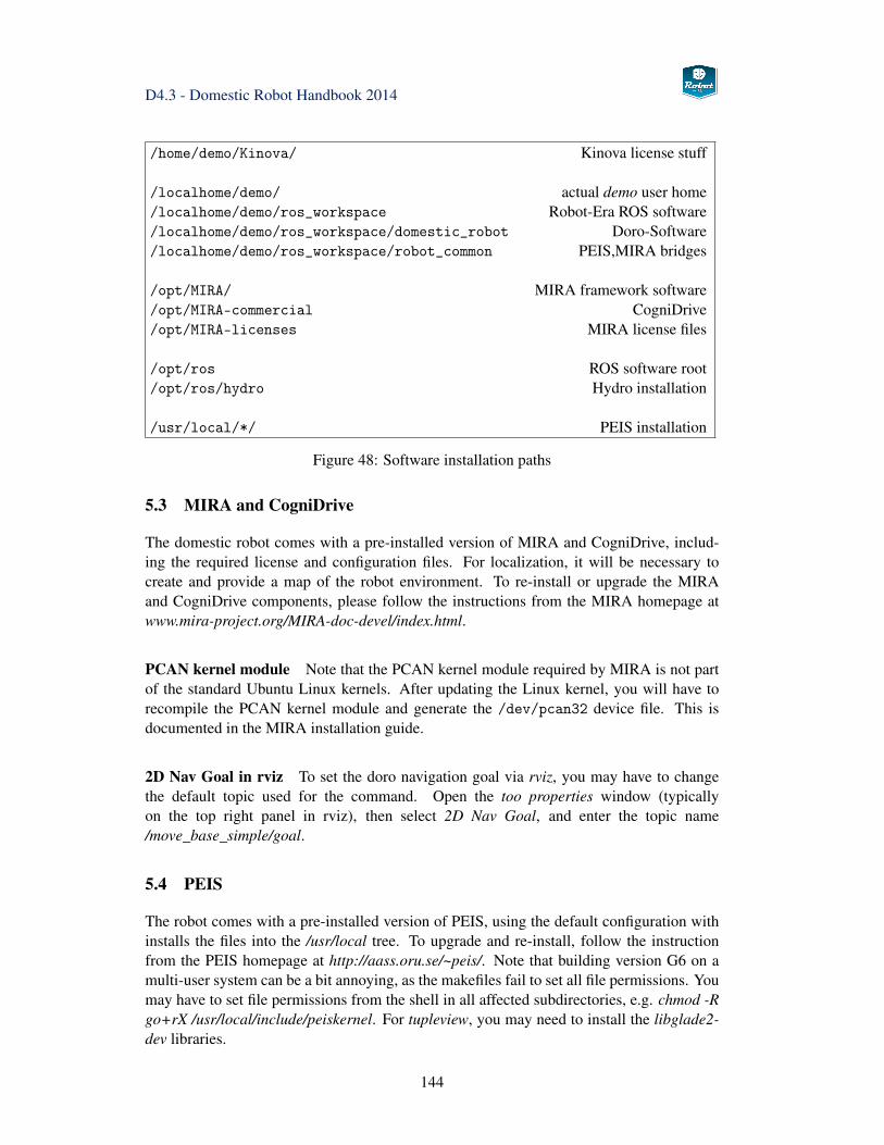
D4.3 - Domestic Robot Handbook 2014
/home/demo/Kinova/ Kinova license stuff
/localhome/demo/ actual demo user home/localhome/demo/ros_workspace Robot-Era ROS software/localhome/demo/ros_workspace/domestic_robot Doro-Software/localhome/demo/ros_workspace/robot_common PEIS,MIRA bridges
/opt/MIRA/ MIRA framework software/opt/MIRA-commercial CogniDrive/opt/MIRA-licenses MIRA license files
/opt/ros ROS software root/opt/ros/hydro Hydro installation
/usr/local/*/ PEIS installation
Figure 48: Software installation paths
5.3 MIRA and CogniDrive
The domestic robot comes with a pre-installed version of MIRA and CogniDrive, includ-ing the required license and configuration files. For localization, it will be necessary tocreate and provide a map of the robot environment. To re-install or upgrade the MIRAand CogniDrive components, please follow the instructions from the MIRA homepage atwww.mira-project.org/MIRA-doc-devel/index.html.
PCAN kernel module Note that the PCAN kernel module required by MIRA is not partof the standard Ubuntu Linux kernels. After updating the Linux kernel, you will have torecompile the PCAN kernel module and generate the /dev/pcan32 device file. This isdocumented in the MIRA installation guide.
2D Nav Goal in rviz To set the doro navigation goal via rviz, you may have to changethe default topic used for the command. Open the too properties window (typicallyon the top right panel in rviz), then select 2D Nav Goal, and enter the topic name/move_base_simple/goal.
5.4 PEIS
The robot comes with a pre-installed version of PEIS, using the default configuration withinstalls the files into the /usr/local tree. To upgrade and re-install, follow the instructionfrom the PEIS homepage at http://aass.oru.se/~peis/. Note that building version G6 on amulti-user system can be a bit annoying, as the makefiles fail to set all file permissions. Youmay have to set file permissions from the shell in all affected subdirectories, e.g. chmod -Rgo+rX /usr/local/include/peiskernel. For tupleview, you may need to install the libglade2-dev libraries.
144
D4.3 - Domestic Robot Handbook 2014
Once building is complete, simply run tupleview in a terminal to check that the systemworks, and to watch the current state of the PEIS tuple-space.
For performance reasons, it is recommended to use known PEIS owner-IDs whenever pos-sible. The default ID of the configuration planner is 995. Further details about PEIS and theinstallation of the configuration planner can be found in deliverable D3.2 [54].
5.5 Kinova Jaco Software
The Kinova Jaco software is pre-installed on the domestic robot. When necessary, re-installfrom the USB-stick suppled by Kinova. Change to the subdirectory with the Ubuntu soft-ware, and follow the installation instructions from the readme.txt file. For example,
cd /media/kinova_usbstick/Release_2012-02-15/4 - API [4.0.5.7]/Ubuntu
If a first-time installation fails, the license files for the robot may not have been created. Aworkaround for this case is to install the software on an Windows PC, and later copy thecreated license files to the robot.
When compiling the software, you will need the mono-devel and mono-gmcs packages.Also install the latest version of libusb-devel.
Note that the Kinova stack is a required dependency for building the domestic robotROS software. However, when just compiling the software for us in Gazebo simula-tion, the actual hardware interfaces are not required. Therefore, it is possible to just putROS_NOBUILD files in the jaco_node, jaco_test_node and jaco_api nodes, and then run-ning rosmake in the domestic robot stacks.
The two reference positions for the arm are:
• retract : -1.5717 -2.0940 1.0982 -1.5329 3.0482 2.7943
• home : -1.7891 -2.0163 0.7994 -0.8739 1.6888 -3.1031
5.6 ROS Hydro
On Ubuntu 12.04 LTS, simply install the required pre-built packages for ros-hydro-xxx viaapt-get or a GUI-tool like synaptic. This installs all files below the opt/ros/hydro directorytree.
ROS Hydro is the currently supported version. The different sensor and actuatorsystems of the Domestic Robot, as well as the MoveIt-based motion planning are im-plemented and tested using ROS Hydro.
145
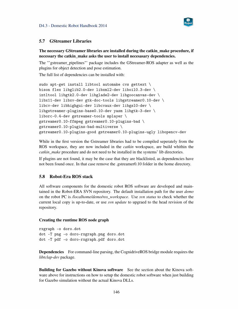
D4.3 - Domestic Robot Handbook 2014
5.7 GStreamer Libraries
The necessary GStreamer libraries are installed during the catkin_make procedure, ifnecessary the catkin_make asks the user to install necesasary dependencies.The "’gstreamer_pipelines"’ package includes the GStreamer-ROS adapter as well as theplugins for object detection and pose estimation.
The full list of dependencies can be installed with:
sudo apt-get install libtool automake cvs gettext \bison flex libglib2.0-dev libxml2-dev liboil0.3-dev \intltool libgtk2.0-dev libglade2-dev libgoocanvas-dev \libx11-dev libxv-dev gtk-doc-tools libgstreamer0.10-dev \libcv-dev libhighgui-dev libcvaux-dev libgsl0-dev \libgstreamer-plugins-base0.10-dev yasm libgtk-3-dev \liborc-0.4-dev gstreamer-tools mplayer \gstreamer0.10-ffmpeg gstreamer0.10-plugins-bad \gstreamer0.10-plugins-bad-multiverse \gstreamer0.10-plugins-good gstreamer0.10-plugins-ugly libopencv-dev
While in the first version the Gstreamer libraries had to be compiled seperately from theROS workspace, they are now included in the catkin workspace, are build whithin thecatkin_make procedure and do not need to be installed in the systems’ lib directories.
If plugins are not found, it may be the case that they are blacklisted, as dependencies havenot been found once. In that case remove the .gstreamer0.10 folder in the home directory.
5.8 Robot-Era ROS stack
All software components for the domestic robot ROS software are developed and main-tained in the Robot-ERA SVN repository. The default installation path for the user demoon the robot PC is /localhome/demo/ros_workspace. Use svn status to check whether thecurrent local copy is up-to-date, or use svn update to upgraed to the head revision of therepository.
Creating the runtime ROS node graph
rxgraph -o doro.dotdot -T png -o doro-rxgraph.png doro.dotdot -T pdf -o doro-rxgraph.pdf doro.dot
Dependencies For command-line parsing, the CognidriveROS bridge module requires thelibtclap-dev package.
Building for Gazebo without Kinova software See the section about the Kinova soft-ware above for instructions on how to setup the domestic robot software when just buildingfor Gazebo simulation without the actual Kinova DLLs.
146
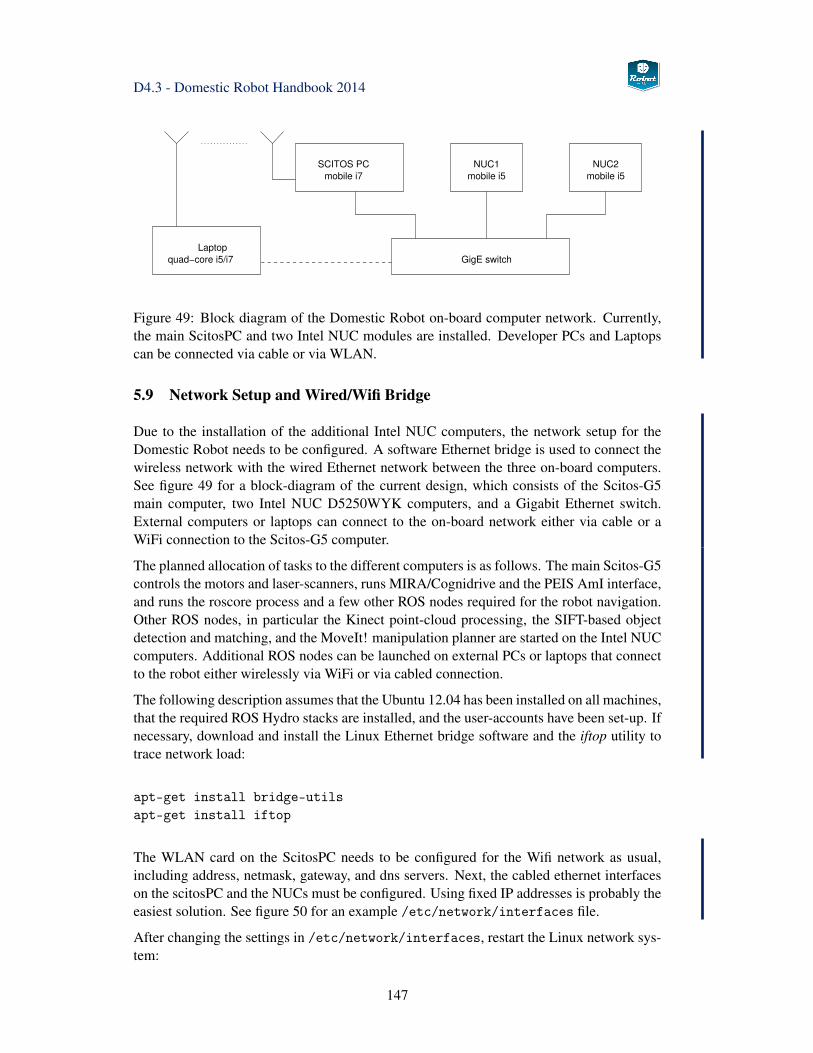
D4.3 - Domestic Robot Handbook 2014
NUC1
mobile i5
NUC2
mobile i5mobile i7
SCITOS PC
GigE switch
Laptop
quad−core i5/i7
Figure 49: Block diagram of the Domestic Robot on-board computer network. Currently,the main ScitosPC and two Intel NUC modules are installed. Developer PCs and Laptopscan be connected via cable or via WLAN.
5.9 Network Setup and Wired/Wifi Bridge
Due to the installation of the additional Intel NUC computers, the network setup for theDomestic Robot needs to be configured. A software Ethernet bridge is used to connect thewireless network with the wired Ethernet network between the three on-board computers.See figure 49 for a block-diagram of the current design, which consists of the Scitos-G5main computer, two Intel NUC D5250WYK computers, and a Gigabit Ethernet switch.External computers or laptops can connect to the on-board network either via cable or aWiFi connection to the Scitos-G5 computer.
The planned allocation of tasks to the different computers is as follows. The main Scitos-G5controls the motors and laser-scanners, runs MIRA/Cognidrive and the PEIS AmI interface,and runs the roscore process and a few other ROS nodes required for the robot navigation.Other ROS nodes, in particular the Kinect point-cloud processing, the SIFT-based objectdetection and matching, and the MoveIt! manipulation planner are started on the Intel NUCcomputers. Additional ROS nodes can be launched on external PCs or laptops that connectto the robot either wirelessly via WiFi or via cabled connection.
The following description assumes that the Ubuntu 12.04 has been installed on all machines,that the required ROS Hydro stacks are installed, and the user-accounts have been set-up. Ifnecessary, download and install the Linux Ethernet bridge software and the iftop utility totrace network load:
apt-get install bridge-utilsapt-get install iftop
The WLAN card on the ScitosPC needs to be configured for the Wifi network as usual,including address, netmask, gateway, and dns servers. Next, the cabled ethernet interfaceson the scitosPC and the NUCs must be configured. Using fixed IP addresses is probably theeasiest solution. See figure 50 for an example /etc/network/interfaces file.
After changing the settings in /etc/network/interfaces, restart the Linux network sys-tem:
147
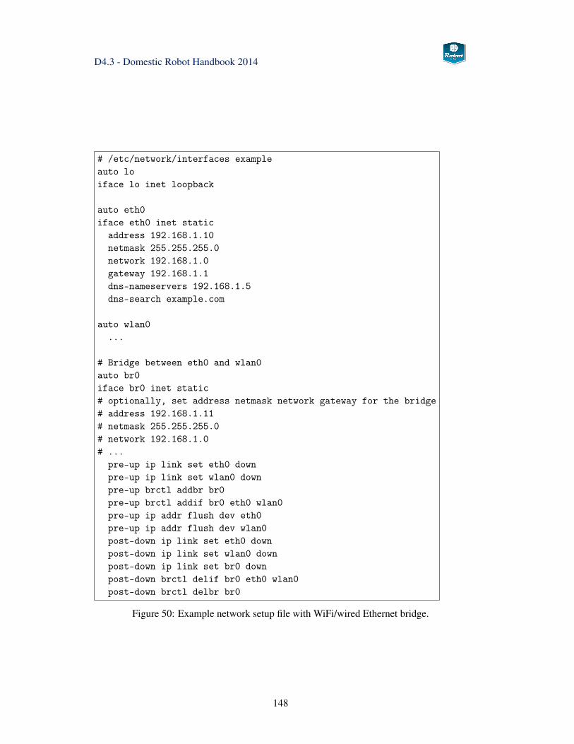
D4.3 - Domestic Robot Handbook 2014
# /etc/network/interfaces exampleauto loiface lo inet loopback
auto eth0iface eth0 inet static
address 192.168.1.10netmask 255.255.255.0network 192.168.1.0gateway 192.168.1.1dns-nameservers 192.168.1.5dns-search example.com
auto wlan0...
# Bridge between eth0 and wlan0auto br0iface br0 inet static# optionally, set address netmask network gateway for the bridge# address 192.168.1.11# netmask 255.255.255.0# network 192.168.1.0# ...
pre-up ip link set eth0 downpre-up ip link set wlan0 downpre-up brctl addbr br0pre-up brctl addif br0 eth0 wlan0pre-up ip addr flush dev eth0pre-up ip addr flush dev wlan0post-down ip link set eth0 downpost-down ip link set wlan0 downpost-down ip link set br0 downpost-down brctl delif br0 eth0 wlan0post-down brctl delbr br0
Figure 50: Example network setup file with WiFi/wired Ethernet bridge.
148
D4.3 - Domestic Robot Handbook 2014
sudo /etc/init.d/networking restart
For testing, the bridge settings can also be configured on the command-line. For example:
brctl addbr br0brctl addif br0 eth0brctl addif br0 wlan0ifconfig br0 up
The network setup must ensure that all machines are known to each other, so that ROSnodes can connect to the main roscore process and exchange messages. Therefore, addthe hostnames/IPs of the three on-board computers as well as all external computers thatshould connect via ROS to the /etc/hosts files on all computers. Please check that theROS_MASTER_URI environment variable is set correctly to point to the main Scitos-G5 con-trol computer:
export ROS_MASTER_URI=http://scitosPC:11311
5.10 Remote Roslaunch Setup
In order to use the ROS roslaunch machine tags for automatic remote execution of nodes,additional network configuration is needed. Because the default Ubuntu client installationonly includes the ssh-client software, the first step is to install the openssh-server packageon all machines that are supposed to run ROS nodes.
apt-get install openssh-server
When using a machine tag inside a roslaunch file, the ROS system creates a ssh-connectionto the specified machine, initializes the path and configuration settings according to thespecified environment shell file, and then tries to execute the specified ROS node with anygiven parameters. This in turn requires that the user that started the roslaunch file can log-into the given machine and executes programs.
There are three different options, namely host-based authorization, password-based autho-rization, and public-key authorization. All mechanisms are documented in detail on theroslaunch Wiki pages. The password-based mechanism is easy to set-up, but requires tokeep both a valid username and the corresponding password in the plain text launch files.This can be accetable on the robot itself if special user accounts are used, but is not recom-mended for normal user-accounts.
The better and secure way is to use the public-key authorization together with an emptypassword. The required key files are created by the user, the private keys are kept private,and only the public keys are copied to the configuration files of the computers that shouldbe accessed. A good tutorial (in German) is http://www.schlittermann.de/doc/ssh.
The first step is to read the required host-keys for all computers that should be able to con-nect via ssh. This includes the on-board control PC, the NUC computers, and any developerlaptops or desktop machines. Enter the IP addresses for all machines to the /etc/hostsfile, and enter the host keys to the /etc/ssh/ssh_known_hosts file:
149
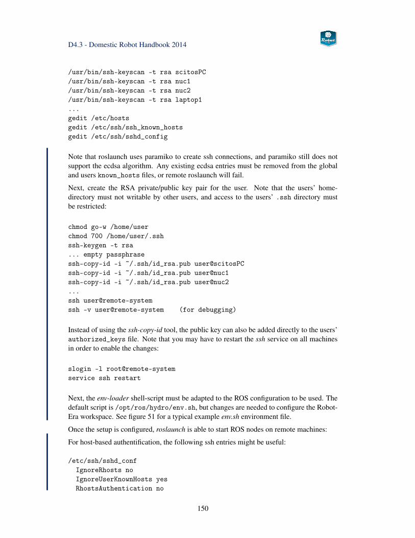
D4.3 - Domestic Robot Handbook 2014
/usr/bin/ssh-keyscan -t rsa scitosPC/usr/bin/ssh-keyscan -t rsa nuc1/usr/bin/ssh-keyscan -t rsa nuc2/usr/bin/ssh-keyscan -t rsa laptop1...gedit /etc/hostsgedit /etc/ssh/ssh_known_hostsgedit /etc/ssh/sshd_config
Note that roslaunch uses paramiko to create ssh connections, and paramiko still does notsupport the ecdsa algorithm. Any existing ecdsa entries must be removed from the globaland users known_hosts files, or remote roslaunch will fail.
Next, create the RSA private/public key pair for the user. Note that the users’ home-directory must not writable by other users, and access to the users’ .ssh directory mustbe restricted:
chmod go-w /home/userchmod 700 /home/user/.sshssh-keygen -t rsa... empty passphrasessh-copy-id -i ~/.ssh/id_rsa.pub user@scitosPCssh-copy-id -i ~/.ssh/id_rsa.pub user@nuc1ssh-copy-id -i ~/.ssh/id_rsa.pub [email protected] user@remote-systemssh -v user@remote-system (for debugging)
Instead of using the ssh-copy-id tool, the public key can also be added directly to the users’authorized_keys file. Note that you may have to restart the ssh service on all machinesin order to enable the changes:
slogin -l root@remote-systemservice ssh restart
Next, the env-loader shell-script must be adapted to the ROS configuration to be used. Thedefault script is /opt/ros/hydro/env.sh, but changes are needed to configure the Robot-Era workspace. See figure 51 for a typical example env.sh environment file.
Once the setup is configured, roslaunch is able to start ROS nodes on remote machines:
For host-based authentification, the following ssh entries might be useful:
/etc/ssh/sshd_confIgnoreRhosts noIgnoreUserKnownHosts yesRhostsAuthentication no
150
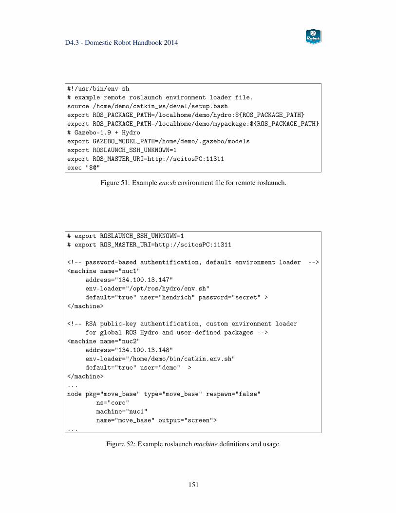
D4.3 - Domestic Robot Handbook 2014
#!/usr/bin/env sh# example remote roslaunch environment loader file.source /home/demo/catkin_ws/devel/setup.bashexport ROS_PACKAGE_PATH=/localhome/demo/hydro:${ROS_PACKAGE_PATH}export ROS_PACKAGE_PATH=/localhome/demo/mypackage:${ROS_PACKAGE_PATH}# Gazebo-1.9 + Hydroexport GAZEBO_MODEL_PATH=/home/demo/.gazebo/modelsexport ROSLAUNCH_SSH_UNKNOWN=1export ROS_MASTER_URI=http://scitosPC:11311exec "$@"
Figure 51: Example env.sh environment file for remote roslaunch.
# export ROSLAUNCH_SSH_UNKNOWN=1# export ROS_MASTER_URI=http://scitosPC:11311
<!-- password-based authentification, default environment loader --><machine name="nuc1"
address="134.100.13.147"env-loader="/opt/ros/hydro/env.sh"default="true" user="hendrich" password="secret" >
</machine>
<!-- RSA public-key authentification, custom environment loaderfor global ROS Hydro and user-defined packages -->
<machine name="nuc2"address="134.100.13.148"env-loader="/home/demo/bin/catkin.env.sh"default="true" user="demo" >
</machine>...node pkg="move_base" type="move_base" respawn="false"
ns="coro"machine="nuc1"name="move_base" output="screen">
...
Figure 52: Example roslaunch machine definitions and usage.
151
D4.3 - Domestic Robot Handbook 2014
RhostsRSAAuthentication yes
/etc/ssh/ssh_configRhostsAuthentication noRhostsRSAAuthentication yes
5.11 Robot calibration
See section 3.1.8 for details.
152
D4.3 - Domestic Robot Handbook 2014
6 Summary
This reports describes the hardware and software setup of the Robot-Era Domestic Robot(Doro) in preparation for the second experimental loop of the project.
Notable updates following analysis of the first experimental phase include a complete re-design of the outer appearance of the robot to improve user acceptance. The hardware itselfwas only slightly changed, with a new mount position of the Jaco arm and the main pillarresulting in a significantly larger object transportation tray and better observability. A gyro-scope sensor improves robot localization, especially on slippery or wet floor. Two compacton-board computers were added to increase the available processing power.
The overall software architecture developd during 2012 and 2013 was largely unchanged,but almost all software modules were updated to new versions and compatibility with ROSHydro. The PEIS-ROS interface was redesigned completely and is now using PEIS meta-tuples for easier reconfiguration of the services. Several robot skills were added for thesecond experimental loop, and most skills were tuned and updated for better robustness.
The last chapter of this handbook list the main software modules required for robot opera-tion and includes installation instructions and tips for troubleshooting.
153
D4.3 - Domestic Robot Handbook 2014
References
[1] E. Olson, AprilTag: A robust and flexible visual fiducial system, Proc. ICRA 2011,3400–3407, 2011.
[2] A. Richardson, J. Strom, E. Olson, AprilCal: Assisted and repeatable camera cali-bration, Proc. IROS 2013.
[3] Groothuis, Stramigioli, Carloni: Lending a helping hand: toward novel assistiverobotic arms, Robotics and Automation Magazine, March 2013,
[4] Xu and Cakmak, Enhanced Robotic Cleaning with a low-cost Tool Attachment, Proc.IROS 2014.
[5] Reflexxes Motion Library, http://www.reflexxes.com/
[6] T. Kroeger, On-Line Trajectory Generation in Robotic Systems, Springer Tracts inAdvanced Robotics, Vol. 58, Springerverlag, Berlin/Heidelberg, Germany, January2010.
[7] N. Hendrich, H. Bistry, B. Adler, J. Zhang, User-driven software design for an elderlycare service robot, Proc. 8th Int. Conference on Pervasive Computing Technologiesfor Healthcare, Pervasive Health 2014, Oldenburg, Germany
[8] N. Hendrich, H. Bistry, J. Liebrecht, J. Zhang, Multi-modal clues for efficient human-robot object handover: a case study with elderly users, Workshop on New frontiersof service robotics for the elderly, RO-MAN 2014, Edinburgh, UK
[9] N. Hendrich, H. Bistry, J. Liebrecht, J. Zhang, Natural Robot-Human HandoverCombining Force and Tactile Sensors, Workshop on Assistance and Service Roboticsin a Human Environment, IROS 2014, Chicago, USA
[10] N. Hendrich, H. Bistry, J. Zhang, PEIS, MIRA, and ROS: Three frameworks, oneservice robot - a tale of integration, ROBIO 2014, Bali, Indonesia, accepted
[11] H. Bistry, Intelligente Kamerasysteme im Anwendungsfeld mobiler Service-Roboter,(Smart Camera Systems in the Application Field of Mobile Service Robots), PhD-thesis, University of Hamburg, 2014
[12] S. Starke, Fast and Robust People Detection on RGB-D Data, MSc-project, Univer-sity of Hamburg, 2014
[13] C. Ferrari and J. Canny; Planning Optimal Grasps In Proceedings of the IEEE Int.Conference on Robotics and Automation, pages 2290–2295, Nice, France, 1992.
[14] K.B. Shimoga, Robot grasp synthesis algorithms: a survey, International Journal ofRobotics Research, vol.15, 230–266, 1996
[15] A. Bicchi, V. Kumar, Robotic grasping and contact: A review, IEEE InternationalConference of Robotics and Automation, 348–353, 2000
154
D4.3 - Domestic Robot Handbook 2014
[16] M.R. Cutkosky, On grasp choice, grasp models, and the design of hands for man-ufacturing tasks, IEEE Transactions on Robotics and Automation, vol.5, 269–279,1989
[17] H. Kjellström, J. Romero, D. Kragic, Visual Recognition of Grasps for Human-to-Robot Mapping, Proc. 2008 IEEE/RSJ International Conference on IntelligentRobots and Systems, 3192–3197, 2008
[18] J. Aleotti, S. Caselli, Grasp Recognition in Virtual Reality for Robot Pregrasp Plan-ning by Demonstration, IEEE Intl. Conference on Robotics and Automation, 2801-2806, 2006
[19] R.S. Dahiya, G. Metta, M. Valle, G. Sandini, Tactile Sensing—From Humans to Hu-manoids, IEEE Transactions on Robotics, vol. 26, no.1, 1–20, 2010
[20] Ch. Borst, M. Fischer and G. Hirzinger; Grasp Planning: How to Choose a SuitableTask Wrench Space. Proceedings of the IEEE Intl. Conference on Robotics andAutomation (ICRA), New Orleans, USA, 2004.
[21] A.T. Miller, S. Knoop, H.I. Christensen, P.K. Allen, Automatic grasp planning usingshape primitives, IEEE Internation Conference on Robotics and Automation, 1824–1829, 2003
[22] J. Kim, J. Park, Y. Hwang, M. Lee; Advanced Grasp Planning for Handover Op-eration Between Human and Robot: Three Handover Methods in Esteem EtiquettesUsing Dual Arms and Hands of Home Service Robot, 2nd Intl. Conference on Au-tonomous Robots and Agents, 2004
[23] M. Turk and A. Pentland, Eigenfaces for recognition. Journal of Cognitive Neuro-science 3 (1): 71–86, 1991.
[24] N. Koenig, and A. Howard, Design and use paradigms for gazebo, an open-sourcemulti-robot simulator, Proc. IROS 2004, 2149–2154
[25] Bullet Physics Library, http://bulletphysics.org/, 2006
[26] Hao Dang, Jonathan Weisz, and Peter K. Allen, Blind Grasping: Stable RoboticGrasping Using Tactile Feedback and Hand Kinematics, Proc. ICRA-2011, 2011
[27] Rosen Diankov, Openrave: A planning architecture for autonomous robotics,Robotics Institute, Pittsburgh, PA, Tech. Rep., (July), 2008.
[28] A. Morales, T. Asfour, P. Azad, S. Knoop, and R. Dillmann. Integrated grasp plan-ning and visual object localization for a humanoid robot with five-fingered hands. InProc. of IROS 2006, 2006.
[29] Z. Li R. Murray and S. Sastry. A Mathematical Introduction to Robotic Manipulation.CRC Press, Boca Raton, FL, 1994.
[30] Marc Peter Deisenroth, Carl Edward Rasmussen, and Dieter Fox. Learning to con-trol a low-cost manipulator using data-efficient reinforcement learning. In Robotics:Science and Systems, 2011.
155
D4.3 - Domestic Robot Handbook 2014
[31] Abhinav Gupta, Aniruddha Kembhavi, and Larry Davis. Observing human-object interactions: Using spatial and funcitional compatibility for recognition.IEEE Transactions on Pattern Analysis and Machine Intelligence, 31(10):1775–1789, 2009.
[32] Anis Sahbani, Jean-Philippe Saut, and Veronique Perdereau. An efficient algorithmfor dexterous manipulation planning. In IEEE International Multi-Conference onSystems, Signals and Devices, 2007.
[33] D. Fox, W. Burgard, and S. Thrun, The Dynamic Window Approach to CollisionAvoidance, 1997
[34] O. Brock and O. Khatib, High-speed Navigation using the Global Dynamic WindowApproach, Proc. ICRA-99, 341–346, 1999.
[35] M. Quigley, B. Gerkey, K. Conley, J. Faust, T. Foote, J. Leibs, E. Berge, R. Wheeler,and A. Ng, ROS: an open-source Robot Operating System, ICRA Workshop on OpenSource Software, 2009pub1.willowgarage.com/~konolige/cs225B/docs/quigley-icra2009-ros.pdf
[36] K. Hsiao, S. Chitta, M. ciocarlie, E. G. Jones, Contact-Reactive Grasping of Objectswith Partial Shape Information,www.willowgarage.com/sites/default/files/contactreactive.pdf
[37] N. Siegwart, I.R. Nourbakhsh, Introduction to Autonomous Mobile Robots, MITPress, 2004
[38] J. W. Capille, Kinematic and Experimental Evaluation of Commercial Wheelchair-Mounted Robotic Arms, Thesis, University of South Florida, 2010
[39] Metralabs Gmbh, SCITOS-G5 Service Robot, www.metralabs.com
[40] Kinova Inc., Jaco robot arm, www.kinova.ca
[41] Kinova Inc., Inverse kinematics for the Jaco arm, private communication.
[42] Shadow Robot Dextrous Hand, www.shadowrobot.com
[43] Metralabs Gmbh, Cognidrive, xxx, 2012.
[44] Taymans, W. and Baker, S. and Wingo, A. and Bultje, R. and Kost, S. GStreamerApplication Development Manual (0.10.21.3), October 2008,gstreamer.freedesktop.org
[45] Russell Smith, Open Dynamics Engine, 2005, http://www.ode.org
[46] AstroMobile project, www.echord.info/wikis/website/astromobile
[47] Robot-Era project, deliverable D2.1, First report on the robotic services analysis withrespect to elderly users, www.robot-era.eu, 2012.
156
D4.3 - Domestic Robot Handbook 2014
[48] Robot-Era project, deliverable D2.3, First report on the usability and acceptabilityrequirements, www.robot-era.eu, 2012.
[49] Robot-Era project, deliverable D2.4, First report on the S/T requirements of theRobot-Era components, www.robot-era.eu, 2012.
[50] Robot-Era project, deliverable D2.6, Second report on the structures of Robot-Eraservices, www.robot-era.eu, 2014.
[51] Robot-Era project, deliverable D2.7, Second report on the usability and acceptabilityrequirements, www.robot-era.eu, 2014.
[52] Robot-Era project, deliverable D2.8, Second report on the S/T requirements of theRobot-Era components, www.robot-era.eu, 2014.
[53] Robot-Era project, deliverable D3.1, Report on the implementation of the AmI infras-tructure modules, www.robot-era.eu, 2012
[54] Robot-Era project, deliverable D3.2, AmI infrastructure and reasoning services, firstversion, www.robot-era.eu, 2013
[55] Robot-Era project, deliverable D3.3, Lessons learnt from the integration of servicerobots with the AmI infrastructure, www.robot-era.eu, 2014
[56] Robot-Era project, deliverable D3.4, AmI infrastructure and reasoning services, sec-ond version, www.robot-era.eu, 2014
[57] Robot-Era project, deliverable D4.1, Domestic Robot Specification, www.robot-era.eu, 2012.
[58] Robot-Era project, deliverable D4.2, Domestic Robot Handbook, First Domesticrobotic platform prototype for the first experimental loop, www.robot-era.eu, 2013.
[59] Robot-Era project, deliverable D5.2, First Condominium robotic platform prototypefor the first experimental loop, www.robot-era.eu, 2013.
[60] Robot-Era project, deliverable D5.3, Final Condominium robotic platform prototypefor the second experimental loop, www.robot-era.eu, 2014.
[61] Robot-Era project, deliverable D6.3, Integration and implementation of the out-door robotic platform prototype for the second experimental loop, www.robot-era.eu,2014.
[62] Robot-Era project, deliverable D8.2, Report on results obtained in the first cycle ofthe Robot-Era experimentation, www.robot-era.eu, 2014.
[63] Robot-Era project, deliverable D8.3, Experimental protocol for the second cycle ofexperiments of Robot-Era services, www.robot-era.eu, 2014.
157