Embed Size (px)
Citation preview

SOFT ROTOR DESIGNFOR FLEXIBLE TURBINES
Flemming Rasmussen (Risø)Jørgen Thirstrup Petersen (Risø)
Per Vølund (Risø)Philippe Leconte (ONERA)
Edmond Szechenyi (ONERA)Carsten Westergaard (LM Glasfiber A/S)
Risø National Laboratory, Roskilde, Denmark
Contract JOU3-CT95-0062
PUBLISHABLE FINAL REPORT
01.01.1996 to 30.06.1998
Research funded in part byTHE EUROPEAN COMMISSION
in the framework of theNon Nuclear Energy Programme
JOULE III

2
Abstract
The project has consisted in development and testing of a two-bladed soft rotor for an existing15 kW flexible wind turbine. The new concept is characterised as a free yawing down windturbine with nacelle tilting flexibility and a two-bladed teetering rotor with three-pointsupported blades with build-in structural couplings. The power and the loads are controlled byactive stall and active coning.
The project has constituted a design process, however with the main emphasis ondetermination of optimal characteristics for the turbine, perceived as a universal concept.
The concept has been developed by extensive application of aeroelastic predictions,numerical optimisation and stability analysis in order to obtain optimal aeroelastic responseand minimal loads. The calculations and succeeding model tests have been performedparticularly for a 13 m diameter rotor, but all conceptual design principles have been focusedon application to large MW turbines. The intention with this has been to make the resultsgenerally applicable and not limited to the development of the specific wind turbine.
The flexible blades and the principle of active coning allows the blades to deflect with thewind to such an extent that the loads are much reduced during stand still in extreme winds.Comparisons of predictions for this concept and a similar rigid rotor show that the blade androtor loads are reduced to between 25 and 50 % during operation as well as during stand stillin extreme winds. This, however, is not a universal ratio for the relation between the loads onthe two concepts. In particular this relation depends upon the size of the turbine.
The aeroelastic predictions have covered normal operation, stand still in extreme winds andabnormal upwind operation. Corresponding conditions have been investigated with theprototype turbine, and the measurements have to a large extent verified the predicted turbinecharacteristics. The turbine has been operating perfectly in all conditions, and it has as a resultof the experiments and measurements not been necessary to correct one single parametersetting, in order to obtain the estimated optimal characteristics – not even the blade pitchsetting.
The work has confirmed that substantial load reductions can be obtained for this concept incomparison to the traditional ones, and that the applied calculation tools are applicable evenfor such an extreme configuration.
Altogether the experience from conducting the project is that the resulting design represents aframe for a quite universal concept that contains great potentials for future detaileddevelopments and refinements.
Research funded in part by THE EUROPEAN COMMISSION in the framework of the NonNuclear Energy Programme JOULE 3.EC.
Contract JOR3-CT-0062 “Soft Rotor Design”
Parts of the work performed by Risø has been funded by The Danish Ministry of Energy through theproject: “Design af fleksibel rotor til dynamisk aktiv mølle” EFP-95 contract ENS-1363/95-0002

3
Contents
Partnership
1. Objectives 5
2. Technical description 6
2.1 Introduction 6
2.2 Aerodynamic design 7
2.3 Structural dynamic design 9
2.4 Design of the soft rotor 11
2.5 Test and evaluation 14
3. Results and conclusions 18
4. Exploitation plans and anticipated benefits 19
5. References 19
4
Partnership
The project has been carried out by the following persons:
Participant Institution
Flemming Rasmussen Risø National LaboratoryJørgen Thirstrup Petersen P.O. Box 49Per Vølund Wind Energy and Atmospheric Physics,
DK-4000 Denmark
Philippe Leconte ONERAEdmond Szechenyi, 29, Ave de la Division Leclerc
BP 72F-92322 Chatillon CédexFrance
Carsten Westergaard LM Glasfiber A/SRolles Møllevej 1DK-6640 LunderskovDenmark

5
1. Objectives
The ultimate objectives of the project are to improve the performance and show the prospectsfor cost effectiveness of flexible wind turbine designs. This will be achieved by bringing newadvanced technological know-how to the design of optimal soft rotors for stall regulated, freeyawing, free-tilting, teetered two-bladed wind turbines. The project will result in the designand manufacture of a rotor. A demonstration will be made on an existing flexible windturbine, developed and erected at Risø. The measurement of its performance and the turbine’soverall unsteady behaviour as compared to the use of present “stiff” rotors will show to whatextent the set objectives have been attained.
The project aims at initiating entirely new technological advances with potentials for thedevelopment of wind turbines of all sizes.
The starting point for the project is the ongoing Risø concept development work, which hasresulted in a turbine that is designed to operate super critically with respect to most of thefundamental natural frequencies. The turbine is free yawing, downwind with nacelle tiltingflexibility and nearly free teeter. This combination of degrees of freedom is new and theactual turbine has been in continuous operation for almost one year showing excellentstability.
The project consists in a development of this 15 kW turbine from relatively, stiff teeteringrotor to a flexible rotor by taking advantage of structural coupling between differentcomponent deflections, in order to obtain optimal aerodynamic and dynamic characteristicsunder load. Even though the resulting turbine design can be used directly for a small scaleturbine, all conceptual design principles and calculation methods are focused on application tolarge turbines.
The work content involves the application of advanced computational tools includingoptimisation for design of the rotor with respect to aerodynamics (planform, airfoil geometryand tip shape), structural dynamics, and structures. Structural dynamic design comprisescomprehensive flutter analysis taking torsional degrees of freedom and dynamic stall modelsinto account. The structural design process includes the possibility to build blades havingdesigned flexible characteristics.
The preconditions for the design of the soft rotor is that it should suit the existing turbine withrespect to rotational speed, maximum power and loads and the concept characterised by freeyaw, downwind and tilting flexibility. The intention is to reconsider some of the fundamentalparameters that are not usually taken into account in the rotor design process and investigatepossible potentials by application of new features.

6
2. Technical description
2.1 Introduction
The main objective of the project has been to demonstrate the potential in flexible windturbine design, by application of new advanced aeroelastic prediction tools to the design ofoptimal soft rotors. The project tasks have covered development, design, manufacture andtesting of a two-bladed soft rotor for an existing 15 kW flexible wind turbine. The newconcept is characterised as a free yawing down wind turbine with nacelle tilting flexibilityand a two-bladed teetering rotor with hinged blades that are controlled by active stall andactive coning. The “hinging” of the blades is obtained by a three-point support structure withbuilt-in structural couplings.
The work has covered the following work packages:
Aerodynamic design,Structural dynamic design,Structural design,Manufacture,Testing/measurements andEvaluation.
The project constitutes a design process, which on the basis of a certain design philosophyrepresents a chain of well argumented decisions, leading consistently to the final design.However, in this project the emphasis has been on the theoretical investigations thatdetermine the characteristics and the principles and on the verification of this bymeasurements rather than on the detailed design work.
The concept has been developed by extensive application of aeroelastic predictions,numerical optimisation and stability analysis aiming at obtaining optimal aeroelastic responseand minimal loads. The calculations and succeeding model tests have been performedparticularly for a 13 m diameter rotor, but all conceptual design principles have been focusedon application to large MW turbines. The intention has been to make the results generallyapplicable in order to establish a general basis for a universal concept, rather than limiting thedevelopment to the specific wind turbine.
The idea has been to reconsider some of the fundamental parameters that are not usually takeninto account in the rotor design process and to investigate possible potentials by application ofnew features. Much effort on too deviating and advanced design features could, however,defuse concentration with respect to the main achievements. An identification andquantification of a potential, thus, does not mean that the feature necessarily should beimplemented in the prototype design, but could be an opportunity for possible futureoptimisation of the soft rotor concept.
After the initial calculations, which were based on characteristics corresponding to the originalrotor of the Risø experimental turbine, the new LM 6.1 m blade was defined as the state of the artin blade aerodynamic design and chosen as a new starting point for the soft rotor development.All further calculations were performed by parametric variations around the characteristics of thisblade.

7
2.2 Aerodynamic design
Adaptable blade geometry has proven to possess some potentials both with respect to energyproduction, loads and stability. Adaptable blade geometry could be realised through largedeformations with loading or build-in structural couplings between e.g. flapwise bending andblade twist or airfoil shape. These subjects have been further treated in the report, and somefeatures are built into the final design. The potentials with respect to adaptable airfoil shapewith loading were not investigated specifically, but the final design is prepared for this featurein that the blade is designed as a pure shell without spars. Furthermore, this is to some extentequivalent to adaptable twist.
An investigation was performed of the potentials for energy output increase by using variablegeometry with wind speed by application of numerical optimisation. Realistic blade geometrycharacteristics were assumed to be variables, in particular the pitch setting and the twistdistribution. An optimum collective pitch setting with wind speed resulted in a yearly energyincrease of 2.7 %, relative to fixed pitch operation. Assuming an optimum twist distributionfor all operational conditions resulted accordingly in a 5.5 % increase.
The resulting optimum twist distribution as a function of radial station and wind speed isillustrated in Figure 1 (Ref.1).
Figure 1. Optimum twist distribution
There is a gradual increase in optimum twist with wind speed, however, only up to 11 m/s,and above this speed the relation is adverse. This behaviour is difficult to obtain by structuralcoupling without applying advanced active control, so this characteristic is not applied for theprototype concept. However, the final design has semi-pitchable blades as airbrake systemand is thus prepared for active stall regulation, which means that the collective pitch setting isvery easy to apply, and the optimum twist distribution is then a realistic option for furtherdevelopments.
The emphasis concerning the blade planform has been on the blade axis shape, which is usuallynot taken into account as a design parameter. An investigation was performed with differentposition of the blade axis relative to a line through the rotor centre. The spanwise flow velocitiesare different in the separated regions for these cases, however, the conclusion is, that thedifference is assumed to have minor impact on the pressure distribution and thus lift-coefficient,
Twist vs. RadiusTwist Variation
-505
1015202530354045
1,000
1,500
2,000
2,500
3,000
3,500
4,000
4,500
5,000
5,500
6,000
6,500
Radius (m)
Twis
t (de
gree
s)
3m/s
4m/s
5m/s
6m/s
7m/s
8m/s
9m/s
10m/s
11m/s
Original

8
except very close to the root. Also at the tip there are differences, which are expected to affect thenoise emission.
A soft rotor design might give rise to high coning angles and/or large blade deflections. Thiscondition would violate one of the fundamental assumptions in the blade element momentumtheory.
An investigation was performed of how the out of plane blade axis shape or swept rotorsurface shape affects the rotor efficiency. Four different shapes were investigated usingNavier-Stokes simulations of the flow field, with volume forces applied to the rotor surface.The different shapes correspond to a straight rotor, a straight rotor with winglets, a conedrotor and a coned rotor with high tip deflection (flexible rotor) as illustrated in Figure 2. Thedifferent rotors were compared on the condition of equal projected swept area and equalthrust coefficient and uniform load distribution in radial direction. The result in the form ofaxial flow velocities along the radial position for the four rotors is illustrated in Figure 3 (Ref.2).
The investigation has revealed the important finding that the induced velocities for straightversus coned or flexible rotors are different at the same radial station, and locally theefficiency can exceed the Betz’ limit, however, when integrating over the whole rotorprojected area, there is no net difference. This means that the total efficiency is equal for allrotors, independent of out of plane shape.
Figure 2. Different rotor configurations

9
.
Titel:plot.epsOprettet af:gnuplot 3.5 (pre 3.6) patchlevel beta 340Eksempel:EPS-billedet blev ikke gemtmed et eksempel.Kommentar:EPS-billedet kan udskrives på enPostScript printer, men ikke påandre printere.
Figure 3. Axial flow velocities for different rotor configurations
A soft rotor that is suited for operation at high coning angles should be designed e.g. withrespect to twist distribution by correction for the lower induced velocities at the inboard bladesections.
The blade tip shape has been subject to some considerations concerning noise andaerodynamic damping. The roll-up of the tip vortex on the blade surface is important for theaerodynamic noise, and the development and extent of separation at the tip determines theaerodynamic damping, which at the tip is of particular importance in order to avoid stall-induced vibrations. This problem was solved by application of flap/edge blade coupling at theblade hinge. As there was no aerodynamic advantage by application of a soft tip, it wasdecided to use the existing tip shape of the LM 6.1 m blade, which meant that it is notnecessary to modify the mould at the tip end.
The conclusion from the detailed aerodynamic investigations was that, altogether there are novery important arguments for modifying the aerodynamic characteristics of the LM 6.1 mblade in order to fulfil the objectives and demonstrate the feasibility of soft rotor design. Thismeans that the modifications could be limited to the structural dynamic characteristics andstructural design.
2.3 Structural dynamic design
An important objective of the project has been to show which potentially favourable degrees offreedom can be accounted for in the design phase in order to obtain a light weight, simple andstable turbine. The emphasis has been on subjects that are beyond the usual wind turbine designconsiderations.
The basis for the structural dynamic design has been aeroelastic modelling of the turbine indifferent configurations [4], [5]. All calculations were performed by parametric variations aroundthe characteristics of the LM 6.1 m blade, and numerical optimisation was applied in order toestimate the optimum combination of some of the characteristics.

10
Six different concepts were defined by combination of the existing turbine and the LM 6.1 mblade in a 13 m diameter rotor configuration with assumed different structural properties. Thisrepresents concepts from rigid hub rotor with distributed flexibility, over hinged rotor to hingedblades with different flap/pitch couplings.
An extensive parametric study was conducted by setting parameters corresponding to theabove defined configurations and running aeroelastic predictions at three different windspeeds. The wind speeds correspond to operation before stall, in stall and beyond stall,respectively. One test case was defined as a step change in wind direction, from which thetotal turbine dynamics is reflected and can be compared between the various configurations.The conclusion from the evaluation of the overall advantage of the different configurationswas that a certain combination of flexibility in both teeter hinge and blade root is mostoptimal. This means that the concept had converged towards one with all characteristicsintegrated: the teetering rotor with blade root flexure and any favourable structural coupling.
The parametric study thus led to the selection of five main characteristics to be used asoptimisation variables : the teeter and flex-beam stiffnesses, the amount of δ3 coupling on theteeter and on the flex-beam and finally the radial position of the hinge simulating the flex-beam. Some side constraints were set on the optimisation variables, Usually corresponding tocertain minimum and maximum values, in order to allow for a realistic dimensioning of theturbine.
The optimisation was carried out at different wind speeds. Each solution was thenrecalculated at the other wind speeds in order to see whether the optimum found at one speedalso yielded gain under different wind conditions.
Figure 4 presents the values of the optimisation variables for different weighting functions forthe unsteady flap moment (F) and the torque fluctuation (T) for the optimum designs. One cansee that both the flex-beam stiffness and δ3 coupling present some variation with wind speedas well as with the weighting function. A positive δ3 coupling value on the teeter hinge meansthat when the blade at the top position is deflected downwind, the angle of attack is increasedon this blade. A negative δ3 coupling value of the flex-beam means that when the blade isdeflected downwind, its angle of attack is decreased.
This procedure led to the choice of the best solution, being in fact a compromise between thevarious gains obtained at different wind speeds. The selected design was then calculated overa wide range of wind speeds, ranging from 5 m/s to 25 m/s. This was done to check whetherthe optimum significantly improved the overall aeroelastic behaviour of the turbine and toassure that the optimum was not only local.
These optimisations led to the optimal characteristics for the rotor, which was then theprecondition for the design and construction work.

11
Figure 4. Values of the optimisation variable
2.4 Design of the soft rotor
In order to arrive at a realistic (or universal) solution, it was decided to consider the airbrakeas a requirement for the soft rotor design. Numerous considerations lead to the decision ofusing the blade pitch function as a basis for the design of the air brake system. Thisfurthermore gives the opportunity for the concept in the future to include the principle ofactive stall, which will be advantageous for large turbines.
The design considerations for the blade led to a solution, where the blade practically onlyconsists of the shell, which constitutes the aerodynamic shape, and a flex-beam that isdesigned to give the optimum blade flapwise stiffness and damping characteristics. Thismeans that the blade has no spar or webs and thus has potentials for very light weight andfuture application of adaptable airfoil geometry.
The flex-beam is a sandwich construction in glass-fibre and rubber, which gives favourabledamping characteristics [3] with respect to stall-induced vibrations and yaw-stability.
Alternatively to the traditional blade root flange, the new concept applies a three-pointsupport of the blades that in principle is applicable independent of wind turbine size. Two ofthe points constitute flap hinges at the leading and trailing edges. The third point transfers theflapwise bending moment through a flex-beam of well-defined stiffness – the value of whichdepends highly on the size of the wind turbine. This is due to the fact that the centrifugalstiffening, by up-scaling with similarity, will decrease relative to the aerodynamic forces. Theprinciple offers the possibility to cone the blades 90o so that they are aligned with the wind inorder to reduce blade and tower loads at stand still in extreme winds.

12
The airbrake function is obtained by pitching of the blades approximately 15o negative, whichfurther offers the possibility for adjustable pitch angle and thus active stall-regulation.
For the actual manufactured turbine, the two control possibilities are only obtained by manualadjustment. A picture of the final turbine is given in Figure 5.
In summary the final concept is characterised by:
Two-bladed teetering rotor.Hinged blades with flap/edge-coupling that is controlled by both active stall andactive coning.Free-yawing downwind turbine.Nacelle tilt flexibility.
Figure 5. The flexible turbine during the measurement campaign

13
During the design phase compromises were made with respect to some of the less importantoptimal characteristics, in order to facilitate manufacture and testing. Comprehensivecalculations were performed once more with parameter values corresponding to thoseobtained for the finally manufactured turbine. In some cases comparisons were made tocalculations for a corresponding teetering rotor turbine with rigid blades. This comparison isillustrated in Figure 6 and 7 for the flapwise blade bending moment and the axial thrust,respectively. It is revealed that these loads are much reduced for the soft rotor designcompared to the teetering rotor.
Figure 6. Statistics of flap moment in operation for a teetering rotor with soft and rigidblades, respectively.

14
Figure 7. Statistics of thrust for a teetering rotor with soft and rigid blades, respectively.
One of the imaginable problems with the free yawing soft rotor design is the possibility forthe downwind rotor to yaw 180 degrees into upwind position, as a response to an unusualturbulence- or gust input. This is particularly critical if the turbine is stable in yaw in upwindoperation. The prediction of the yaw behaviour revealed that the turbine in upwind operationis unstable in yaw at wind speeds below 8 m/s and above 12 m/s, however, in the range 8-12m/s, there is a risk that it is stable in the unwanted position.
The risk for upwind operation was taken into account in the design phase by applyingincreased blade hinge stiffness for negative deflection of the blades, and by application ofsufficient blade tower distance.
2.5 Test and evaluation
The measurements on the turbine were performed with the primary objective to verify that theconcept resulting from the design process has the desired characteristics on a more generallevel. The objectives of the measurements have thus been to verify the characteristics of thenew concept, rather than to verify the aeroelastic code in detail. The design andinstrumentation of the turbine has not in all cases allowed a “clean” measurement ofcorresponding predicted parameters, however, the ambition has been to design a prototyperather than a test turbine.
The flexible blades and the principle of active coning allows the blades to deflect with thewind to such an extent that the loads are much reduced during stand still in extreme winds.Comparisons of predictions for this concept and a similar rigid rotor shows that the blade androtor loads are reduced to between 25 and 50 % during operation as well as during stand stillin extreme winds. This, however, is not a universal ratio for the relation between the loads onthe two concepts. In particular this relation depends on the size of the turbine.
In order to illustrate the reduced loads for the soft rotor, the statistics for the measuredflapwise blade bending moment is illustrated in Figure 8.

15
Figure 8 Statistics for the flap moment in operation.
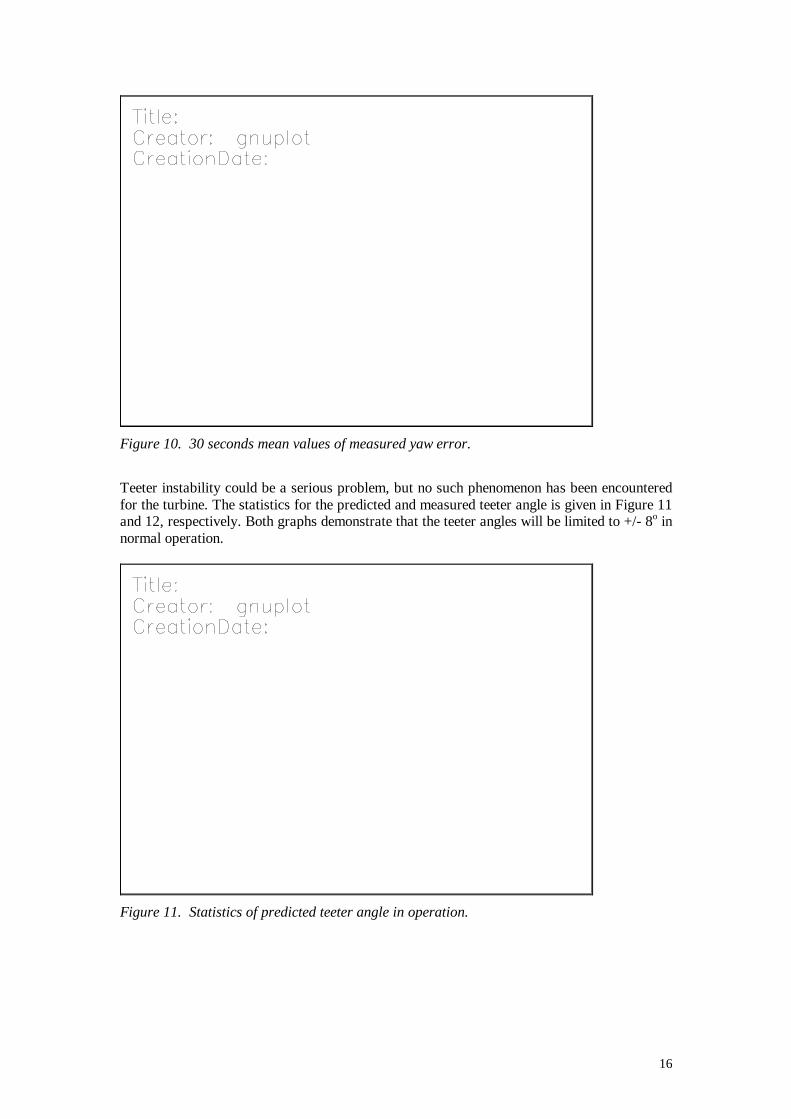
The yaw stability reflects the important characteristics for the turbine, as it is determined asthe resulting response of the sum of the main forces on the turbine. The mean yaw angle ispredicted to be very close to zero degrees, except for very low wind speeds, where there is atendency for positive yawing, as reflected in Figure 9. This was also the case for themeasurements that are presented in Figure 10.
Figure 9 Statistics of predicted yaw angle in operation.
16
Figure 10. 30 seconds mean values of measured yaw error.
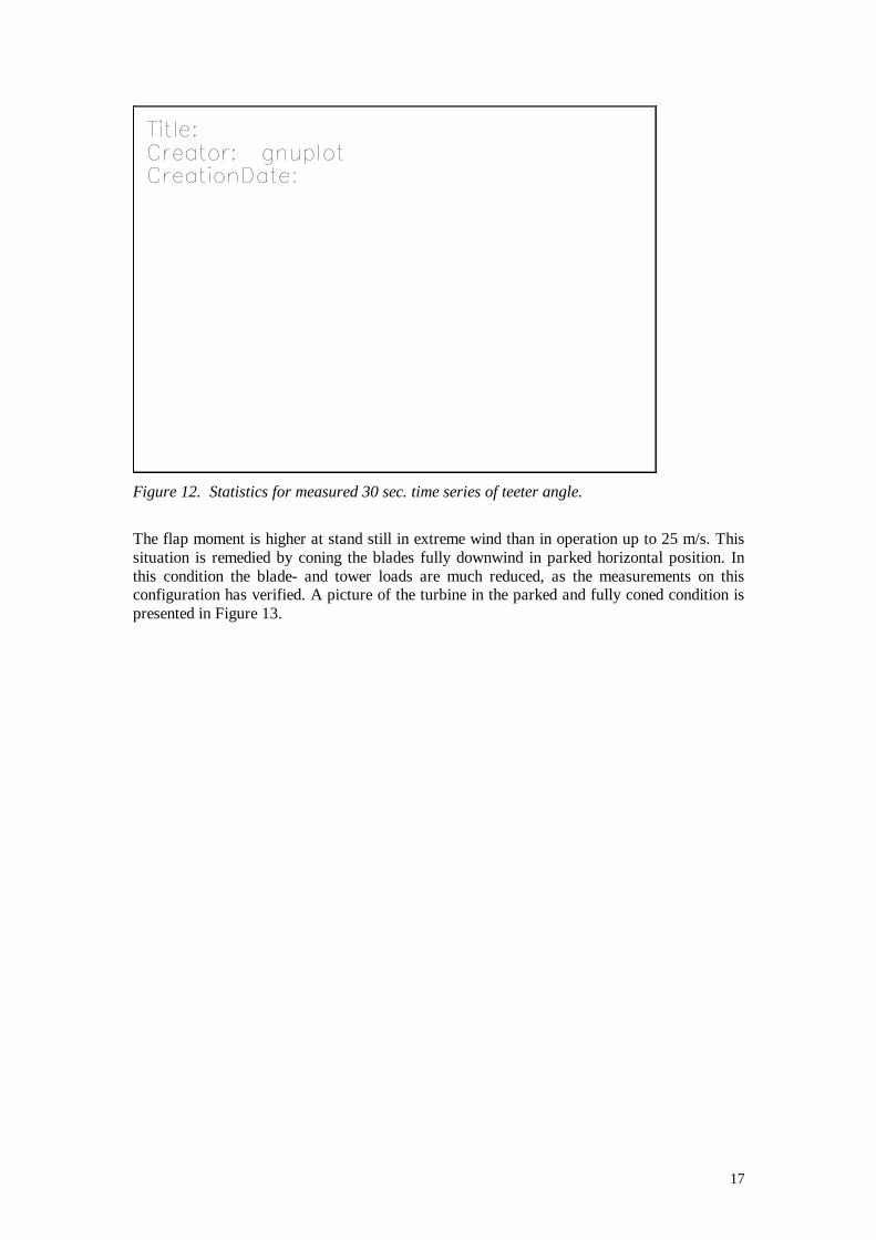
Teeter instability could be a serious problem, but no such phenomenon has been encounteredfor the turbine. The statistics for the predicted and measured teeter angle is given in Figure 11and 12, respectively. Both graphs demonstrate that the teeter angles will be limited to +/- 8o innormal operation.
Figure 11. Statistics of predicted teeter angle in operation.
17
Figure 12. Statistics for measured 30 sec. time series of teeter angle.
The flap moment is higher at stand still in extreme wind than in operation up to 25 m/s. Thissituation is remedied by coning the blades fully downwind in parked horizontal position. Inthis condition the blade- and tower loads are much reduced, as the measurements on thisconfiguration has verified. A picture of the turbine in the parked and fully coned condition ispresented in Figure 13.

18
Figure 13. The turbine with the blades at 80° coning.
3. Results and conclusions
Advanced aeroelastic predictions in combination with numerical optimisation and stabilityanalysis have been developed and applied in the design process of a 13 m diameter soft rotor,aiming at establishment of a verified design tool for soft rotors in order to obtain optimalaeroelastic response and minimal loads.
The design process has covered development, design, manufacture and testing of a two-bladed soft rotor for an existing 15 kW flexible turbine. The new concept is characterised as afree yawing down wind turbine with nacelle tilting flexibility and a two-bladed teetering rotorwith hinged blades that are controlled by active stall and active coning. The blades have built-in structural coupling. The aeroelastic optimisations have been performed particularly for the13 m diameter rotor, but all conceptual design principles have been focused on application tolarge MW turbines.

19
The aeroelastic predictions have covered normal operation, stand still in extreme winds andabnormal upwind operation. Corresponding conditions have been investigated with themanufactured prototype turbine, and the measurements have to a large extent verified theestimated turbine characteristics and thus the design tools.
The flexible blades and the principle of active coning allows the blades to deflect with thewind in order to reduce the loads. The loads are reduced to between 25 and 50 % duringoperation as well as during stand still in extreme winds for this concept in comparison with asimilar one with a rigid teetering rotor. The work has thus confirmed that substantial loadreductions can be obtained for this concept in comparison to the traditional ones, and that theapplied calculation tools are applicable even for such an extreme configuration.
The turbine has been operating perfectly in all conditions, and it has as a result of theexperiments and measurements not been necessary to correct one single parameter setting, inorder to obtain the estimated optimal characteristics – not even the blade pitch setting.
Altogether the experience from conducting the project is that the resulting design represents ageneral basis for a quite universal concept that contains great potentials for future detaileddevelopments and refinements.
4. Exploitation plans and anticipated benefits
The manufactured and tested soft rotor turbine is a scale model prototype for demonstrationof the design tools. The real application is intended to be the design of a large MW turbine ofthe soft rotor concept. This requires the cooperation with a manufacturer of large windturbines. While the conducted project also included the development of the concept, theexploitation of the result is limited to be focused on up-scaling. The aeroelastic predictionsand optimisations can be done with the existing tools, however, a substantial investment intechnology transfer, further development, detailed design, manufacture and testing of a MW-size prototype turbine is foreseen.
All together the innovative features of the result are new ways to limit steady and unsteadyloads on wind turbines, which has a high commercial potential, however, it requires muchknow-how on wind turbine technology and high investments.
5. References
[1] Bak, Christian; Aerodynamic optimisation of a two-bladed wind turbine. Risø-I-1343(DA), Risø National Laboratory, November 1998.
[2] Madsen, Helge Aagaard; Rasmussen, Flemming; Fact-sheet AED-RB-5 “Flexibleblades and coning changes the efficiency locally”, Risø National Laboratory, July1998.
[3] Mortensen, Peter R., ”Dæmpning for Flexbeam til tobladet vindmølle”, d 94 22 32,Technical University of Denmark, October 1998.
[4] Petersen, J.T.; The Aeroelastic Code HawC – Model and Comparisons”. Inproceedings of ”State of the Art of Aeroelastic Codes for Wind TurbineCalculations”. 28th Meeting of Experts, International Energy Agency, Annex XI.Technical University of Denmark, Lyngby, Denmark. April 1996, pp. 129-135.
[5] Leconte, P.; Szechenyi, E.; ”Aeroelastic Tailoring of Blades: Prospects for ReducingUnsteady Loads and Enhancing Performance”, EUWEC ’96, Göteborg.


