Embed Size (px)
Citation preview
MARINECONTROL UNITS
L-5508 | Form No. 341205 20210420 | ©2021 Dometic Corporation
WARNINGCancer and Reproductive Harm
www.P65Warnings.ca.gov
Passport I/O Legacy, Passport I/O Compact, AH-Passport I/O Legacy, AH-Passport I/O Compact
EN Passport I/O Digital ControlsInstallation and Operation Manual . . . . . . . .2
2 EN
Contents Passport I/O Digital Controls
Contents . . . . . . . . . . . . . . . . . . . . . . . . . . . . . . . . . . 2
1 Explanation of Symbols and Safety Instructions . . . . . . . . . . . . . . . . . . . . . . . . . . . . 2
1.1 Recognize Safety Information . . . . . . . . . . . . . 2
1.2 Understand Signal Words . . . . . . . . . . . . . . . . 3
1.3 Supplemental Directives . . . . . . . . . . . . . . . . . 3
1.4 General Safety Messages . . . . . . . . . . . . . . . . 3
2 Intended Use . . . . . . . . . . . . . . . . . . . . . . . . . . . 3
3 General Information . . . . . . . . . . . . . . . . . . . . . 4
3.1 Tools and Materials . . . . . . . . . . . . . . . . . . . . . 4
3.2 Display Features . . . . . . . . . . . . . . . . . . . . . . . 4
4 Specifications . . . . . . . . . . . . . . . . . . . . . . . . . . 5
4.1 Product Dimensions . . . . . . . . . . . . . . . . . . . . 5
4.2 Cable Length . . . . . . . . . . . . . . . . . . . . . . . . . . 5
4.3 Available System Inputs . . . . . . . . . . . . . . . . . . 6
4.4 Operational Specifications . . . . . . . . . . . . . . . 6
5 Wiring Diagrams . . . . . . . . . . . . . . . . . . . . . . . . 7
6 Installation . . . . . . . . . . . . . . . . . . . . . . . . . . . . . 8
6.1 Choosing a Display Panel Location. . . . . . . . . 9
6.2 Preparing the Wall . . . . . . . . . . . . . . . . . . . . . . 9
6.3 Installing an Optional Sensor . . . . . . . . . . . . . 9
6.4 Mounting the Display Panel . . . . . . . . . . . . . . 9
7 Operation . . . . . . . . . . . . . . . . . . . . . . . . . . . . . 10
7.1 Understanding the Heating and Cooling Cycles . . . . . . . . . . . . . . . . . . . . . . . . . . . . . . 10
7.2 Understanding the Service Utility Commands (DX Systems Only) . . . . . . . . . . . 12
7.3 Turning on the Passport Control . . . . . . . . . . 12
7.4 Choosing the Passport Control Operation . 12
7.5 Using the Passport Control Display Panel . . 14
7.3 Programming the Passport Control . . . . . . . 16
7.4 Navigation Tree . . . . . . . . . . . . . . . . . . . . . . .22
8 Maintenance . . . . . . . . . . . . . . . . . . . . . . . . . . 23
8.1 Testing the Passport Control . . . . . . . . . . . . .23
8.2 Checking the Return-Air Filter . . . . . . . . . . . .23
8.3 Energizing the Reversing Valve Units (DX Systems Only) . . . . . . . . . . . . . . . . . . . . .23
8.4 Checking the Seawater Strainer (DX Systems Only) . . . . . . . . . . . . . . . . . . . . .23
8.5 Cleaning the Condenser Coil (DX Systems Only) . . . . . . . . . . . . . . . . . . . . .24
8.6 Winterizing the System (DX Systems Only) . .24
9 Troubleshooting . . . . . . . . . . . . . . . . . . . . . . . 25
10 Disposal . . . . . . . . . . . . . . . . . . . . . . . . . . . . . . 29
11 Warranty Information . . . . . . . . . . . . . . . . . . . 29
Service Center & Dealer LocationsVisit: www.dometic.com
Please read these instructions carefully and follow all instructions, guidelines, and warnings included in this product manual in order to ensure that you install, use, and maintain the product properly at all times. These instructions MUST stay with this product.
By using the product, you hereby confirm that you have read all instructions, guidelines, and warnings carefully and that you understand and agree to abide by the terms and conditions as set forth herein. You agree to use this product only for the intended purpose and application and in accordance with the instructions, guidelines, and warnings as set forth in this product manual as well as in accordance with all applicable laws and regulations. A failure to read and follow the instructions and warnings set forth herein may result in an injury to yourself and others, damage to your product, or damage to other property in the vicinity. This product manual, including the instructions, guidelines, and warnings, and related documentation, may be subject to changes and updates. For up-to-date product information, please visit www.dometic.com.
Contents
1 Explanation of Symbols and Safety InstructionsThis manual has safety information and instructions to help you eliminate or reduce the risk of accidents and injuries.
1 .1 Recognize Safety Information �This is the safety alert symbol . It is used to alert you to potential physical injury hazards. Obey all safety messages that follow this symbol to avoid possible injury or death.
3EN
Passport I/O Digital Controls Intended Use
1 .2 Understand Signal WordsA signal word will identify safety messages and property damage messages, and also will indicate the degree or level of hazard seriousness.
�DANGER!Indicates a hazardous situation that, if not avoided, will result in death or serious injury.
�WARNINGIndicates a hazardous situation that, if not avoided, could result in death or serious injury.
�CAUTIONIndicates a hazardous situation that, if not avoided, could result in minor or moderate injury.
NOTICE: Used to address practices not related to physical injury.
I Indicates additional information that is not related to physical injury.
1 .3 Supplemental DirectivesTo reduce the risk of accidents and injuries, please observe the following directives before proceeding to install or operate this appliance:
• Read and follow all safety information and instructions.
• Read and understand these instructions before installing and operating this product.
• The installation must comply with all applicable local or national codes, including the latest edition of the following standards:
– ANSI/NFPA70, National Electrical Code (NEC)
– American Boat and Yacht Council (ABYC)
1 .4 General Safety Messages �WARNING: ELECTRICAL SHOCK, FIRE, AND/OR EXPLOSION HAZARD . Failure to obey the following warnings could result in death or serious injury:
• Use only Dometic replacement parts and components that are specifically approved for use with the appliance.
• Avoid improper installation, adjustment, alteration, service, or maintenance of the appliance. Service and maintenance must be done by a qualified service person only.
• Do not modify this product in any way. Modification can be extremely hazardous.
2 Intended UseThe Passport I/O controls and AH-Passport I/O controls (also referred to as “Passport controls”) are 5 V microcontroller-based devices designed for use with direct expansion (DX), reverse-cycle air-conditioning systems, and chilled-water systems (CW).
The Passport controls are only suitable for the intended purpose and application in accordance with these instructions.
This manual provides information that is necessary for proper installation and operation of the Passport controls. Poor installation and/or improper operating or maintenance will result in unsatisfactory performance and a possible failure. The manufacturer accepts no liability for any injury or damage to the product resulting from:
• Incorrect assembly or connection, including excess voltage
• Incorrect maintenance or use of spare parts other than original spare parts provided by the manufacturer
• Alterations to the product without express permission from the manufacturer
• Use for purposes other than those described in this manual
Dometic reserves the right to change product appearance and product specifications.
4 EN
General Information Passport I/O Digital Controls
3 General InformationThis section provides information on the tooling, parts, and display features for the Passport controls.
IThe images used in this document are for reference purposes only. Components and component locations may vary according to specific product models. Measurements may vary ±0.38 in. (10 mm).
All Passport control models have similar features, installation procedures, and functionality.
3 .1 Tools and MaterialsDometic recommends that the following tools and materials be used while installing the Passport controls:
Recommended Tools
Phillips-head Screwdriver Saw
Safety Glasses
Included Parts Quantity
Adhesive Strips 2
Passport I/O Control or AH-Passport I/O Control
1
Additional Parts1 DX CW
Required for CW Installations (not included)
Water Inlet Temperature Sensor x
Optional Parts
Air Filter Cleaning or Replacement Timer2
x x
Alternate Air Temperature Sensor x x
Low-Voltage Monitor2 x
Outside Air Temperature (OAT) Sensor
x x
Plastic Bulkhead Adapter x x
Condenser Coil Temperature Sensor (Service Sensor)
x
Pump Sentry Water Sensor x1 Additional parts are not included with the standard Passport control package. 2 Available in software version A21 or newer.
3 .2 Display FeaturesThis section explains the function of the buttons and indicators on the Passport control displays.
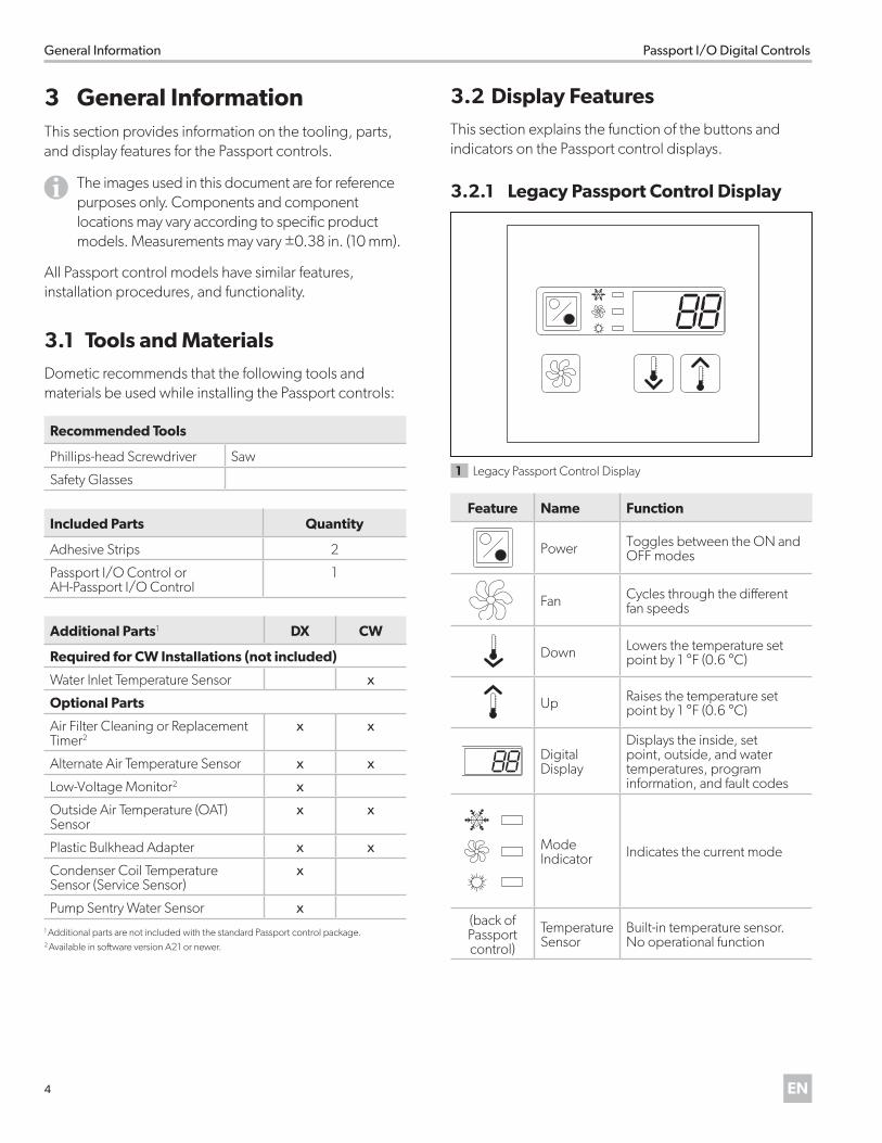
3 .2 .1 Legacy Passport Control Display
1 Legacy Passport Control Display
Feature Name Function
Power Toggles between the ON and OFF modes
Fan Cycles through the different fan speeds
Down Lowers the temperature set point by 1 °F (0.6 °C)
Up Raises the temperature set point by 1 °F (0.6 °C)
Digital Display
Displays the inside, set point, outside, and water temperatures, program information, and fault codes
Mode Indicator Indicates the current mode
(back of Passport control)
Temperature Sensor
Built-in temperature sensor. No operational function
5EN
Passport I/O Digital Controls Specifications
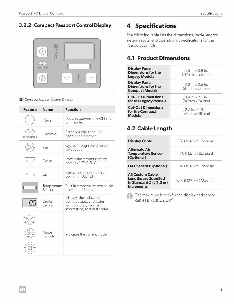
3 .2 .2 Compact Passport Control Display
2 Compact Passport Control Display
Feature Name Function
Power Toggles between the ON and OFF modes
Dometic Brand identification. No operational function
Fan Cycles through the different fan speeds
Down Lowers the temperature set point by 1 °F (0.6 °C)
Up Raises the temperature set point 1 °F (0.6 °C)
Temperature Sensor
Built-in temperature sensor. No operational function
Digital Display
Displays the inside, set point, outside, and water temperatures, program information, and fault codes
Mode Indicator Indicates the current mode
4 SpecificationsThe following table lists the dimensions, cable lengths, system inputs, and operational specifications for the Passport controls.
4 .1 Product Dimensions
Display Panel Dimensions for the Legacy Models
4.5 in. x 3.9 in. (114 mm x 99 mm)
Display Panel Dimensions for the Compact Models
3.2 in. x 2.5 in. (81 mm x 64 mm)
Cut-Out Dimensions for the Legacy Models
3.4 in. x 2.9 in. (86 mm x 74 mm)
Cut-Out Dimensions for the Compact Models
2.5 in. x 1.9 in. (64 mm x 48 mm)
4 .2 Cable Length
Display Cable 15.0 ft (4.6 m) Standard
Alternate Air Temperature Sensor (Optional)
7.0 ft (2.1 m) Standard
OAT Sensor (Optional) 15.0 ft (4.6 m) Standard
All Custom Cable Lengths are Supplied In Standard 5 ft (1 .5 m) Increments
75.0 ft (22.9 m) Maximum
IThe maximum length for the display and sensor cables is 75 ft (22.9 m).
6 EN
Specifications Passport I/O Digital Controls
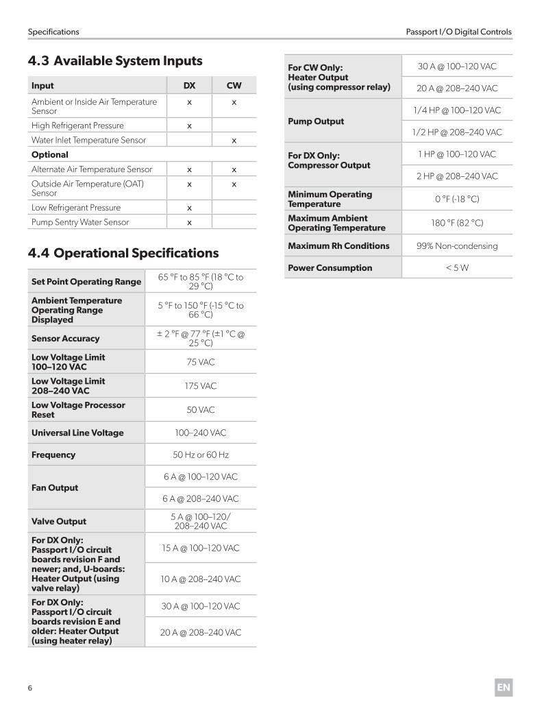
4 .3 Available System Inputs
Input DX CW
Ambient or Inside Air Temperature Sensor
x x
High Refrigerant Pressure x
Water Inlet Temperature Sensor x
Optional
Alternate Air Temperature Sensor x x
Outside Air Temperature (OAT) Sensor
x x
Low Refrigerant Pressure x
Pump Sentry Water Sensor x
4 .4 Operational Specifications
Set Point Operating Range 65 °F to 85 °F (18 °C to 29 °C)
Ambient Temperature Operating Range Displayed
5 °F to 150 °F (-15 °C to 66 °C)
Sensor Accuracy ± 2 °F @ 77 °F (±1 °C @ 25 °C)
Low Voltage Limit 100–120 VAC 75 VAC
Low Voltage Limit 208–240 VAC 175 VAC
Low Voltage Processor Reset 50 VAC
Universal Line Voltage 100–240 VAC
Frequency 50 Hz or 60 Hz
Fan Output 6 A @ 100–120 VAC
6 A @ 208–240 VAC
Valve Output 5 A @ 100–120/ 208–240 VAC
For DX Only: Passport I/O circuit boards revision F and newer; and, U-boards: Heater Output (using valve relay)
15 A @ 100–120 VAC
10 A @ 208–240 VAC
For DX Only: Passport I/O circuit boards revision E and older: Heater Output (using heater relay)
30 A @ 100–120 VAC
20 A @ 208–240 VAC
For CW Only:Heater Output(using compressor relay)
30 A @ 100–120 VAC
20 A @ 208–240 VAC
Pump Output 1/4 HP @ 100–120 VAC
1/2 HP @ 208–240 VAC
For DX Only: Compressor Output
1 HP @ 100–120 VAC
2 HP @ 208–240 VAC
Minimum Operating Temperature 0 °F (-18 °C)
Maximum Ambient Operating Temperature 180 °F (82 °C)
Maximum Rh Conditions 99% Non-condensing
Power Consumption < 5 W
7EN
Passport I/O Digital Controls Wiring Diagrams
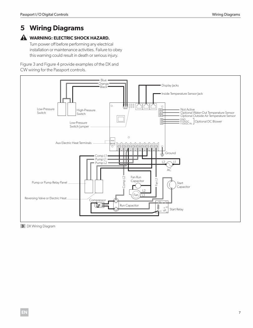
5 Wiring Diagrams �WARNING: ELECTRIC SHOCK HAZARD . Turn power off before performing any electrical installation or maintenance activities. Failure to obey this warning could result in death or serious injury.
Figure 3 and Figure 4 provide examples of the DX and CW wiring for the Passport controls.
Run Capacitor
Low-Pressure Switch
High-Pressure Switch
Comp L1Pump L1Pump L2
BlueOrange
Black
Fan
L1
Com
p L2
Compressor
Display Jacks
Inside Temperature Sensor Jack
Not Active
GND0-10VDC+10VDC IN
Optional Water-Out Temperature SensorOptional Outside Air Temperature Sensor
Optional DC Blower
Ground
Start Capacitor
Start Relay
16
452
L2
AC
Fan
Fan Run Capacitor
L1
L1
L2
Pump or Pump Relay Panel
Aux Electric Heat Terminals
Low-Pressure Switch Jumper
Reversing Valve or Electric Heat
3 DX Wiring Diagram
8 EN
Installation Passport I/O Digital Controls
JP1
Display JacksInside Temperature Sensor Jack
Required Water-In Temperature SensorOptional Water-Out Temperature Sensor
Optional Outside Air Temperature Sensor
JP2
Ground
Fan
Water Valve
Electric Heat Strip
Fan Run Capacitor
L2
L2
L2
AC
L2
L1
L1
L1
L1
Optional DC Blower GND
For Humidistat For Changeover SwitchCOM COM
0-10 VDC
SMX DISPLAYS ONLY
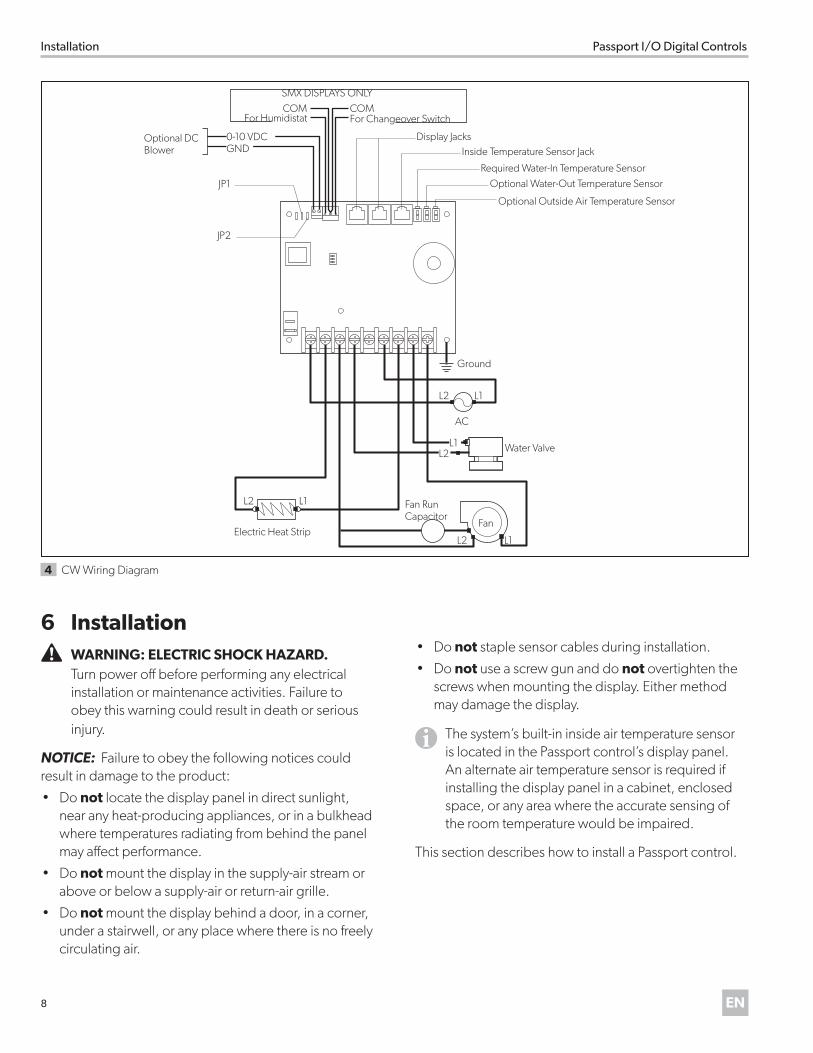
4 CW Wiring Diagram
6 Installation �WARNING: ELECTRIC SHOCK HAZARD . Turn power off before performing any electrical installation or maintenance activities. Failure to obey this warning could result in death or serious injury.
NOTICE: Failure to obey the following notices could result in damage to the product:
• Do not locate the display panel in direct sunlight, near any heat-producing appliances, or in a bulkhead where temperatures radiating from behind the panel may affect performance.
• Do not mount the display in the supply-air stream or above or below a supply-air or return-air grille.
• Do not mount the display behind a door, in a corner, under a stairwell, or any place where there is no freely circulating air.
• Do not staple sensor cables during installation.
• Do not use a screw gun and do not overtighten the screws when mounting the display. Either method may damage the display.
IThe system’s built-in inside air temperature sensor is located in the Passport control’s display panel. An alternate air temperature sensor is required if installing the display panel in a cabinet, enclosed space, or any area where the accurate sensing of the room temperature would be impaired.
This section describes how to install a Passport control.
9EN
Passport I/O Digital Controls Installation
6 .1 Choosing a Display Panel LocationPlace the display panel in an area that meets the following location criteria:• Mounted on an inside wall of the cabin, away from
direct sunlight• Sets slightly higher than mid-height of the cabin• Located in an area of freely circulating air• Placed a maximum distance of 15 ft (4.6 m) from the
air conditioner unit
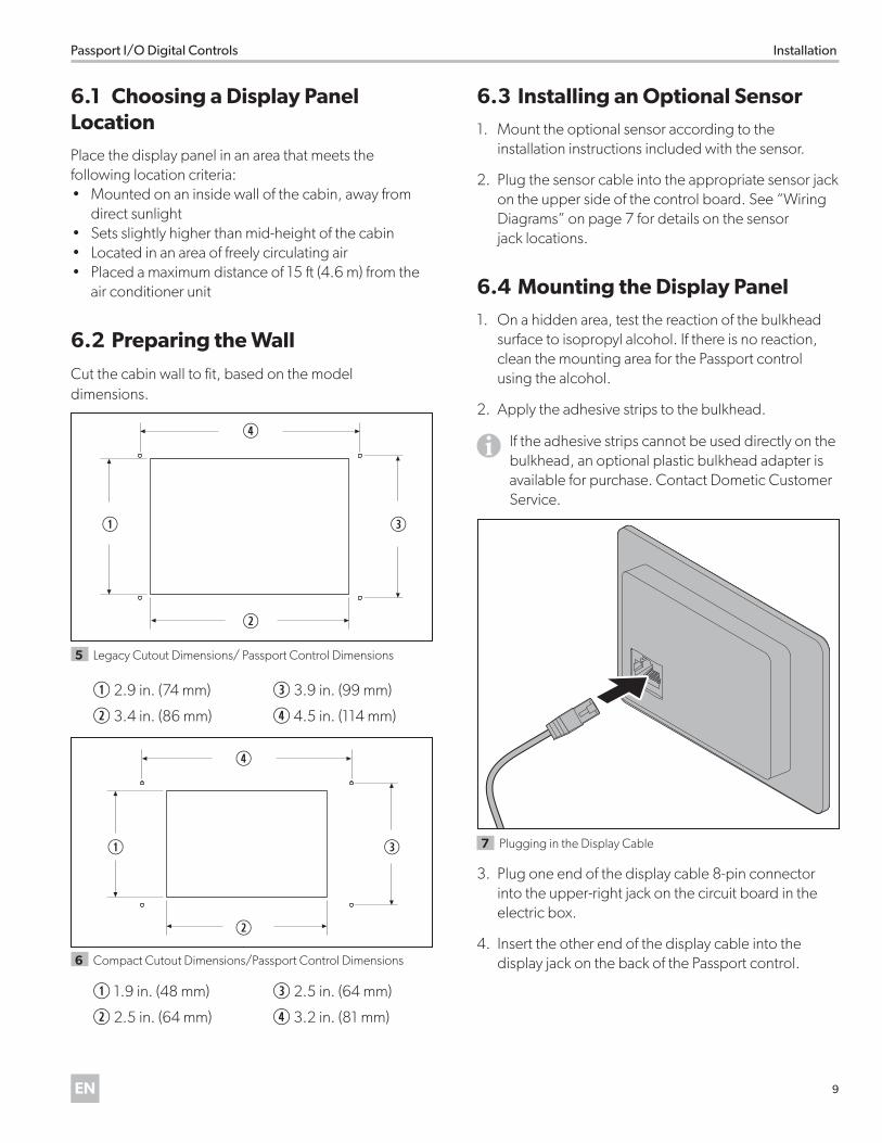
6 .2 Preparing the Wall
Cut the cabin wall to fit, based on the model dimensions.
q
r
e
w
5 Legacy Cutout Dimensions/ Passport Control Dimensions
q 2.9 in. (74 mm) e 3.9 in. (99 mm)
w 3.4 in. (86 mm) r 4.5 in. (114 mm)
q
r
e
w
6 Compact Cutout Dimensions/Passport Control Dimensions
q 1.9 in. (48 mm) e 2.5 in. (64 mm)
w 2.5 in. (64 mm) r 3.2 in. (81 mm)
6 .3 Installing an Optional Sensor1. Mount the optional sensor according to the
installation instructions included with the sensor.
2. Plug the sensor cable into the appropriate sensor jack on the upper side of the control board. See “Wiring Diagrams” on page 7 for details on the sensor jack locations.
6 .4 Mounting the Display Panel1. On a hidden area, test the reaction of the bulkhead
surface to isopropyl alcohol. If there is no reaction, clean the mounting area for the Passport control using the alcohol.
2. Apply the adhesive strips to the bulkhead.
I If the adhesive strips cannot be used directly on the bulkhead, an optional plastic bulkhead adapter is available for purchase. Contact Dometic Customer Service.
7 Plugging in the Display Cable
3. Plug one end of the display cable 8-pin connector into the upper-right jack on the circuit board in the electric box.
4. Insert the other end of the display cable into the display jack on the back of the Passport control.
10 EN
Operation Passport I/O Digital Controls
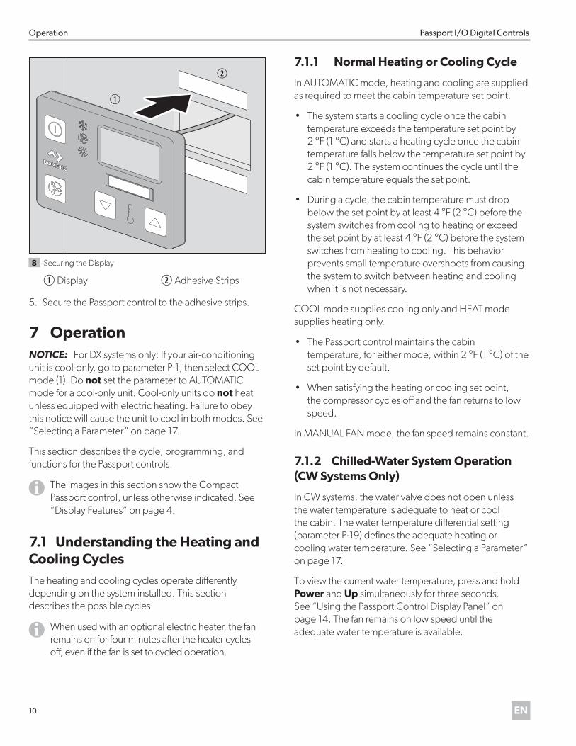
q
w
8 Securing the Display
q Display w Adhesive Strips
5. Secure the Passport control to the adhesive strips.
7 OperationNOTICE: For DX systems only: If your air-conditioning unit is cool-only, go to parameter P-1, then select COOL mode (1). Do not set the parameter to AUTOMATIC mode for a cool-only unit. Cool-only units do not heat unless equipped with electric heating. Failure to obey this notice will cause the unit to cool in both modes. See “Selecting a Parameter” on page 17.
This section describes the cycle, programming, and functions for the Passport controls.
IThe images in this section show the Compact Passport control, unless otherwise indicated. See “Display Features” on page 4.
7 .1 Understanding the Heating and Cooling CyclesThe heating and cooling cycles operate differently depending on the system installed. This section describes the possible cycles.
IWhen used with an optional electric heater, the fan remains on for four minutes after the heater cycles off, even if the fan is set to cycled operation.
7 .1 .1 Normal Heating or Cooling Cycle
In AUTOMATIC mode, heating and cooling are supplied as required to meet the cabin temperature set point.
• The system starts a cooling cycle once the cabin temperature exceeds the temperature set point by 2 °F (1 °C) and starts a heating cycle once the cabin temperature falls below the temperature set point by 2 °F (1 °C). The system continues the cycle until the cabin temperature equals the set point.
• During a cycle, the cabin temperature must drop below the set point by at least 4 °F (2 °C) before the system switches from cooling to heating or exceed the set point by at least 4 °F (2 °C) before the system switches from heating to cooling. This behavior prevents small temperature overshoots from causing the system to switch between heating and cooling when it is not necessary.
COOL mode supplies cooling only and HEAT mode supplies heating only.
• The Passport control maintains the cabin temperature, for either mode, within 2 °F (1 °C) of the set point by default.
• When satisfying the heating or cooling set point, the compressor cycles off and the fan returns to low speed.
In MANUAL FAN mode, the fan speed remains constant.
7 .1 .2 Chilled-Water System Operation (CW Systems Only)
In CW systems, the water valve does not open unless the water temperature is adequate to heat or cool the cabin. The water temperature differential setting (parameter P-19) defines the adequate heating or cooling water temperature. See “Selecting a Parameter” on page 17.
To view the current water temperature, press and hold Power and Up simultaneously for three seconds. See “Using the Passport Control Display Panel” on page 14. The fan remains on low speed until the adequate water temperature is available.
11EN
Passport I/O Digital Controls Operation
ITo provide heat when the required water temperature is not available, install the optional electric heater, and program parameter P-19. See “Programming the Passport Control” on page 16.
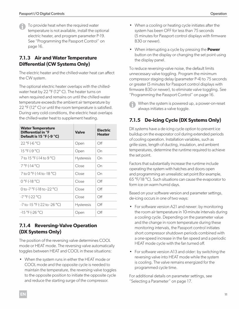
7 .1 .3 Air and Water Temperature Differential (CW Systems Only)
The electric heater and the chilled-water heat can affect the CW system.
The optional electric heater overlaps with the chilled-water heat by 22 °F (12° C). The heater turns on when required and remains on until the chilled-water temperature exceeds the ambient air temperature by 22 °F (12° C) or until the room temperature is satisfied. During very cold conditions, the electric heat overlaps the chilled-water heat to supplement heating.
Water Temperature Differential in °FDefault is 15 °F (-9 °C)
Valve Electric Heater
22 °F (-6 °C) Open Off
15 °F (-9 °C) Open On
7 to 15 °F (-14 to 9 °C) Hysteresis On
7 °F (-14 °C) Close On
7 to 0 °F (-14 to -18 °C) Close On
0 °F (-18 °C) Close Off
0 to -7 °F (-18 to -22 °C) Close Off
-7 °F (-22 °C) Close Off
-7 to -15 °F (-22 to -26 °C) Hysteresis Off
-15 °F (-26 °C) Open Off
7 .1 .4 Reversing-Valve Operation (DX Systems Only)
The position of the reversing valve determines COOL mode or HEAT mode. The reversing valve automatically toggles between HEAT and COOL in these situations:
• When the system runs in either the HEAT mode or COOL mode and the opposite cycle is needed to maintain the temperature, the reversing valve toggles to the opposite position to initiate the opposite cycle and reduce the starting surge of the compressor.
• When a cooling or heating cycle initiates after the system has been OFF for less than 75 seconds (5 minutes for Passport control displays with firmware B30 or newer).
• When interrupting a cycle by pressing the Power button on the display or changing the set point using the display panel.
To reduce reversing-valve noise, the default limits unnecessary valve toggling. Program the minimum compressor staging delay (parameter P-4) to 75 seconds or greater (5 minutes for Passport control displays with firmware B30 or newer), to eliminate valve toggling. See “Programming the Passport Control” on page 16.
IWhen the system is powered up, a power-on-reset always initiates a valve toggle.
7 .1 .5 De-icing Cycle (DX Systems Only)
DX systems have a de-icing cycle option to prevent ice buildup on the evaporator coil during extended periods of cooling operation. Installation variables, such as grille sizes, length of ducting, insulation, and ambient temperatures, determine the runtime required to achieve the set point.
Factors that substantially increase the runtime include operating the system with hatches and doors open and programming an unrealistic set point (for example, 65 °F/18 °C). Such situations can cause the evaporator to form ice on warm humid days.
Based on your software version and parameter settings, de-icing occurs in one of two ways:
• For software version A21 and newer: by monitoring the room air temperature in 10-minute intervals during a cooling cycle. Depending on the parameter value and the change in room temperature during these monitoring intervals, the Passport control initiates short compressor shutdown periods combined with a one-speed increase in the fan speed and a periodic HEAT mode cycle with the fan turned off.
• For software version A13 and older: by switching the reversing valve into HEAT mode while the system is cooling. The valve remains energized for the programmed cycle time.
For additional details on parameter settings, see “Selecting a Parameter” on page 17.
12 EN
Operation Passport I/O Digital Controls
7 .2 Understanding the Service Utility Commands (DX Systems Only)DX systems include service utility commands. This section explains the self-test program, the hours meter, and the service history log.
7 .2 .1 Self-Test Program
The Passport I/O software contains a self-test program to facilitate factory testing of the entire air conditioning system. Once activated, the self-test program continues the test cycle until an interruption in the AC power occurs or the Power button is pressed once to return the system to OFF mode.
7 .2 .2 Hour Meter
The hour meter provides a way to judge a compressor’s longevity based on actual run time.
• The maximum recordable time is 65,536 hours, at which point the meter stops and can only be reset by a service technician.
• The Passport control saves the total cycle time at six-minute intervals while the compressor runs continuously.
• The Passport control discards a cycle time of less than six minutes to conserve memory and allow for flexibility.
7 .2 .3 Service History Log
When a fault occurs in the system, a one-hour timer starts.
• Three consecutive faults within that hour cause a system shut down and lockout, and a fault code shows on the display.
• During the timed hour, to conserve memory, the Passport control does not record recurring faults of the same type.
• Continuous operation for one hour without the same recurring fault clears the fault counter, but the event remains in the service history log until overwritten.
• If a different fault occurs during the hour, it shows on the service history log.
The service history log keeps these faults:
• High Refrigerant Pressure (HPF)
• Low Refrigerant Pressure (LPF)
• Air Sensor Failure (ASF)
• Low AC Voltage (LAC)
• Pump or Loss of Seawater (PLF)
The Passport controls record the eight most recent faults.
7 .3 Turning on the Passport ControlTo power on the Passport control, press and immediately release the Power button.
NOTICE: Avoid unintentionally entering the Programming mode. Programming mode activates when the Power button is pressed and held for more than five seconds. After unintentionally entering Programming mode, any subsequent presses of the Up or Down buttons will change the P-1 parameter setting since it is the first parameter shown after entering this mode. The P-1 parameter changes the operating mode to Cool-Only, Heat-Only, or Automatic, which could result in improper system operation. Always use care when in Programming mode. For further information, see “Choosing the Passport Control Operation” on page 12 and “Programming the Passport Control” on page 16.
7 .4 Choosing the Passport Control OperationThe indicators represent the different modes of the Passport control. The Compact Passport control model indicators are shown in this section. See “Using the Passport Control Display Panel” on page 14 for more detail on mode operation. See “Available Modes and Options for Operation” on page 13 to select a mode.
13EN
Passport I/O Digital Controls Operation
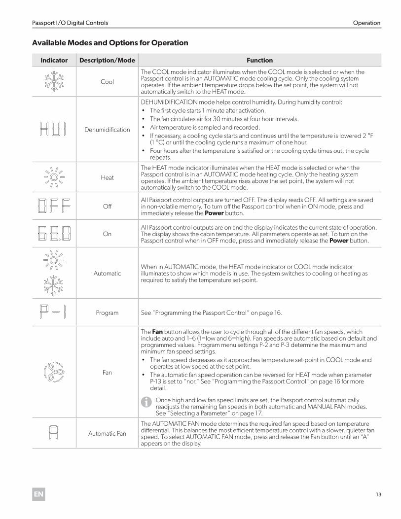
Available Modes and Options for Operation
Indicator Description/Mode Function
Cool
The COOL mode indicator illuminates when the COOL mode is selected or when the Passport control is in an AUTOMATIC mode cooling cycle. Only the cooling system operates. If the ambient temperature drops below the set point, the system will not automatically switch to the HEAT mode.
Dehumidification
DEHUMIDIFICATION mode helps control humidity. During humidity control:• The first cycle starts 1 minute after activation.• The fan circulates air for 30 minutes at four hour intervals. • Air temperature is sampled and recorded. • If necessary, a cooling cycle starts and continues until the temperature is lowered 2 °F
(1 °C) or until the cooling cycle runs a maximum of one hour. • Four hours after the temperature is satisfied or the cooling cycle times out, the cycle
repeats.
Heat
The HEAT mode indicator illuminates when the HEAT mode is selected or when the Passport control is in an AUTOMATIC mode heating cycle. Only the heating system operates. If the ambient temperature rises above the set point, the system will not automatically switch to the COOL mode.
OffAll Passport control outputs are turned OFF. The display reads OFF. All settings are saved in non-volatile memory. To turn off the Passport control when in ON mode, press and immediately release the Power button.
OnAll Passport control outputs are on and the display indicates the current state of operation. The display shows the cabin temperature. All parameters operate as set. To turn on the Passport control when in OFF mode, press and immediately release the Power button.
AutomaticWhen in AUTOMATIC mode, the HEAT mode indicator or COOL mode indicator illuminates to show which mode is in use. The system switches to cooling or heating as required to satisfy the temperature set-point.
Program See “Programming the Passport Control” on page 16.
Fan
The Fan button allows the user to cycle through all of the different fan speeds, which include auto and 1–6 (1=low and 6=high). Fan speeds are automatic based on default and programmed values. Program menu settings P-2 and P-3 determine the maximum and minimum fan speed settings. • The fan speed decreases as it approaches temperature set-point in COOL mode and
operates at low speed at the set point. • The automatic fan speed operation can be reversed for HEAT mode when parameter
P-13 is set to “nor.” See “Programming the Passport Control” on page 16 for more detail.
IOnce high and low fan speed limits are set, the Passport control automatically readjusts the remaining fan speeds in both automatic and MANUAL FAN modes. See “Selecting a Parameter” on page 17.
Automatic Fan
The AUTOMATIC FAN mode determines the required fan speed based on temperature differential. This balances the most efficient temperature control with a slower, quieter fan speed. To select AUTOMATIC FAN mode, press and release the Fan button until an “A” appears on the display.
14 EN
Operation Passport I/O Digital Controls
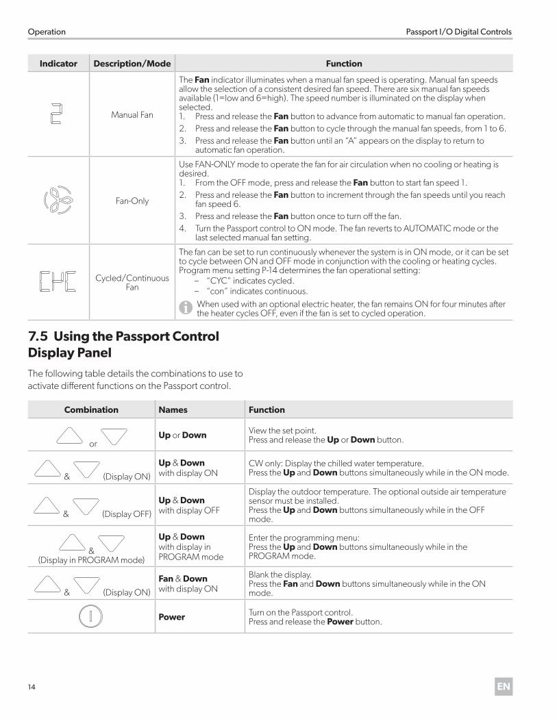
Indicator Description/Mode Function
Manual Fan
The Fan indicator illuminates when a manual fan speed is operating. Manual fan speeds allow the selection of a consistent desired fan speed. There are six manual fan speeds available (1=low and 6=high). The speed number is illuminated on the display when selected. 1. Press and release the Fan button to advance from automatic to manual fan operation. 2. Press and release the Fan button to cycle through the manual fan speeds, from 1 to 6. 3. Press and release the Fan button until an “A” appears on the display to return to
automatic fan operation.
Fan-Only
Use FAN-ONLY mode to operate the fan for air circulation when no cooling or heating is desired. 1. From the OFF mode, press and release the Fan button to start fan speed 1. 2. Press and release the Fan button to increment through the fan speeds until you reach
fan speed 6.3. Press and release the Fan button once to turn off the fan.4. Turn the Passport control to ON mode. The fan reverts to AUTOMATIC mode or the
last selected manual fan setting.
Cycled/Continuous Fan
The fan can be set to run continuously whenever the system is in ON mode, or it can be set to cycle between ON and OFF mode in conjunction with the cooling or heating cycles. Program menu setting P-14 determines the fan operational setting:
– “CYC” indicates cycled. – “con” indicates continuous.
IWhen used with an optional electric heater, the fan remains ON for four minutes after the heater cycles OFF, even if the fan is set to cycled operation.
7 .5 Using the Passport Control Display PanelThe following table details the combinations to use to activate different functions on the Passport control.
Combination Names Function
or Up or Down View the set point.
Press and release the Up or Down button.
& (Display ON)
Up & Down with display ON
CW only: Display the chilled water temperature.Press the Up and Down buttons simultaneously while in the ON mode.
& (Display OFF)
Up & Down with display OFF
Display the outdoor temperature. The optional outside air temperature sensor must be installed.Press the Up and Down buttons simultaneously while in the OFF mode.
& (Display in PROGRAM mode)
Up & Downwith display in PROGRAM mode
Enter the programming menu:Press the Up and Down buttons simultaneously while in the PROGRAM mode.
& (Display ON)
Fan & Downwith display ON
Blank the display.Press the Fan and Down buttons simultaneously while in the ON mode.
Power Turn on the Passport control.Press and release the Power button.
15EN
Passport I/O Digital Controls Operation
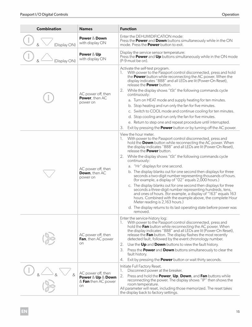
Combination Names Function
& (Display ON)
Power & Downwith display ON
Enter the DEHUMIDIFICATION mode:Press the Power and Down buttons simultaneously while in the ON mode. Press the Power button to exit.
& (Display ON)
Power & Up with display ON
Display the service sensor temperature:Press the Power and Up buttons simultaneously while in the ON mode (P-9 must be on).
AC power off, thenPower, then AC power on
Activate the self-test program.1. With power to the Passport control disconnected, press and hold
the Power button while reconnecting the AC power. When the display indicates “888” and all LEDs are lit (Power-On Reset), release the Power button.
2. While the display shows “tSt” the following commands cycle continuously:a. Turn on HEAT mode and supply heating for ten minutes.b. Stop heating and run only the fan for five minutes.c. Switch to COOL mode and continue cooling for ten minutes.d. Stop cooling and run only the fan for five minutes.e. Return to step one and repeat procedure until interrupted.
3. Exit by pressing the Power button or by turning off the AC power.
AC power off, thenDown, then AC power on
View the hour meter.1. With power to the Passport control disconnected, press and
hold the Down button while reconnecting the AC power. When the display indicates “888” and all LEDs are lit (Power-On Reset), release the Power button.
2. While the display shows “tSt” the following commands cycle continuously:a. “Hr” displays for one second.b. The display blanks out for one second then displays for three
seconds a two-digit number representing thousands of hours. (for example, a display of “02” equals 2,000 hours.)
c. The display blanks out for one second then displays for three seconds a three-digit number representing hundreds, tens, and ones of hours. (for example, a display of “163” equals 163 hours. Combined with the example above, the complete Hour Meter reading is 2,163 hours.)
d. The display returns to its last operating state before power was removed.
AC power off, thenFan, then AC power on
Enter the service-history log:1. With power to the Passport control disconnected, press and
hold the Fan button while reconnecting the AC power. When the display indicates “888” and all LEDs are lit (Power-On Reset), release the Fan button. The display flashes the most recently detected fault, followed by the event chronology number.
2. Use the Up and Down buttons to view the fault history. 3. Press the Power and Down buttons simultaneously to clear the
fault history. 4. Exit by pressing the Power button or wait thirty seconds.
& & & AC power off, then Power & Up & Down & Fan then AC power on
Initiate Full Factory Reset.1. Disconnect power at the breaker.2. Press and hold the Power, Up, Down, and Fan buttons while
reconnecting the power. The display shows “IP” then shows the room temperature.
All parameter will reset, including those memorized. The reset takes the display back to factory settings.
16 EN
Operation Passport I/O Digital Controls
7 .3 Programming the Passport Control
IRead the following important points before programming the Passport control:
• If your air-conditioning unit has a Shaded-Pole (SP) fan motor instead of a Split-Capacitor (SC) High-Velocity (HV) fan motor, program SP into the fan motor type parameter before operating the Passport control. SP units are recognizable by an overhanging blower motor. The SC motor of an HV unit is inside the blower, and the unit has VTD or HV as part of the model number. Only reprogram the fan motor type parameter if you do not have an HV blower.
• Standard air handlers come equipped with chilled-water bypass valves. However, for “no-valve” air handlers, the fan must be set to cycle with the fan in programming parameter P-14. Verify that the installed air handlers have bypass valves; if not, change parameter P-14 to “CYC.”
Use the parameter settings to program and fine-tune the system for the most efficient operation within an installation and to adjust operating parameters for your particular needs. After new values are entered and memorized, the factory defaults are overwritten and the new parameters become the default values.
The Passport controls have a non-volatile memory that requires no batteries or battery backup. The Passport control retains all operating parameters during a loss of power. When power is restored, the Passport control lights all indicators for one second and flashes “888” on the display, then resumes operating according to the last program settings.
The Passport control has factory default values stored in permanent memory (memorized factory default settings) that are available for recall if you have any programming difficulties. You can restore the original factory default parameters manually. See “DISPLAY INDICATORS” on page 22 for a summary of the parameters, the permitted values, and original factory default settings.
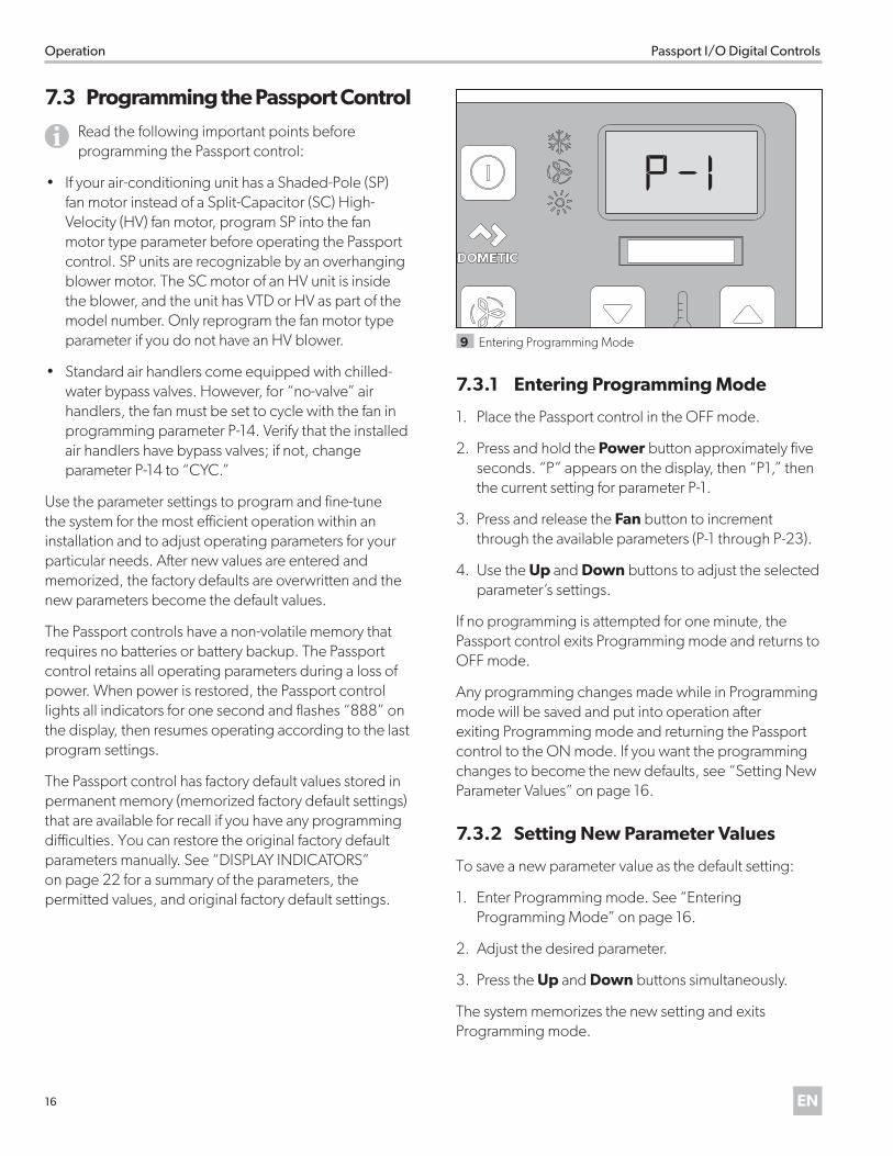
9 Entering Programming Mode
7 .3 .1 Entering Programming Mode
1. Place the Passport control in the OFF mode.
2. Press and hold the Power button approximately five seconds. “P” appears on the display, then “P1,” then the current setting for parameter P-1.
3. Press and release the Fan button to increment through the available parameters (P-1 through P-23).
4. Use the Up and Down buttons to adjust the selected parameter’s settings.
If no programming is attempted for one minute, the Passport control exits Programming mode and returns to OFF mode.
Any programming changes made while in Programming mode will be saved and put into operation after exiting Programming mode and returning the Passport control to the ON mode. If you want the programming changes to become the new defaults, see “Setting New Parameter Values” on page 16.
7 .3 .2 Setting New Parameter Values
To save a new parameter value as the default setting:
1. Enter Programming mode. See “Entering Programming Mode” on page 16.
2. Adjust the desired parameter.
3. Press the Up and Down buttons simultaneously.
The system memorizes the new setting and exits Programming mode.
17EN
Passport I/O Digital Controls Operation
7 .3 .3 Restoring Default Parameter Values
To restore the last memorized default parameter values:
1. Enter Programming mode. See “Entering Programming Mode” on page 16.
2. Set the parameter value for parameter P-17 to “rSt.”
The system restores the memorized default settings and the Passport control returns to OFF mode.
To restore the factory default settings, reset the parameters manually using the factory defaults listed under “Selecting a Parameter” on page 17.
7 .3 .4 Exiting Programming Mode
To exit the programming menu manually, press the Power button once. Alternatively, the display automatically exits the programming menu after 50 seconds of inactivity.
The Passport control’s software version (such as “A24”) appears in the display for one second prior to the manual or automatic exit from programming mode. The Passport control enters OFF mode after exit.
IWhen contacting Dometic regarding the system or about programming the Passport control, note the software version and air conditioning unit serial number. The serial number may be found on the dataplate label of the unit.
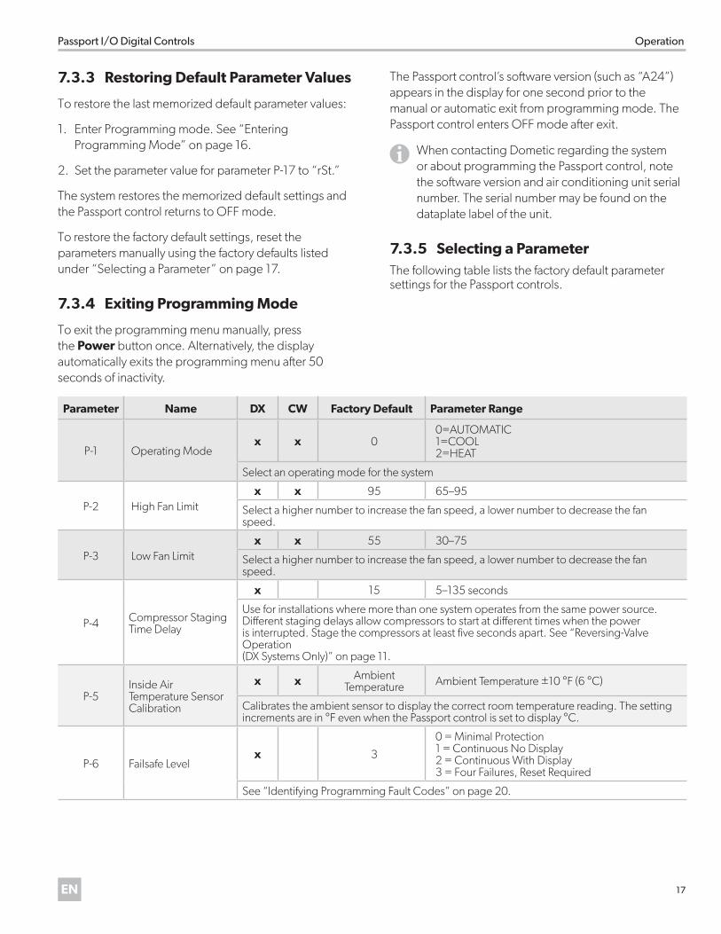
7 .3 .5 Selecting a ParameterThe following table lists the factory default parameter settings for the Passport controls.
Parameter Name DX CW Factory Default Parameter Range
P-1 Operating Modex x 0
0=AUTOMATIC 1=COOL2=HEAT
Select an operating mode for the system
P-2 High Fan Limitx x 95 65–95
Select a higher number to increase the fan speed, a lower number to decrease the fan speed.
P-3 Low Fan Limitx x 55 30–75
Select a higher number to increase the fan speed, a lower number to decrease the fan speed.
P-4 Compressor Staging Time Delay
x 15 5–135 seconds
Use for installations where more than one system operates from the same power source. Different staging delays allow compressors to start at different times when the power is interrupted. Stage the compressors at least five seconds apart. See “Reversing-Valve Operation (DX Systems Only)” on page 11.
P-5Inside Air Temperature Sensor Calibration
x x Ambient Temperature Ambient Temperature ±10 °F (6 °C)
Calibrates the ambient sensor to display the correct room temperature reading. The setting increments are in °F even when the Passport control is set to display °C.
P-6 Failsafe Levelx 3
0 = Minimal Protection1 = Continuous No Display2 = Continuous With Display3 = Four Failures, Reset Required
See “Identifying Programming Fault Codes” on page 20.
18 EN
Operation Passport I/O Digital Controls
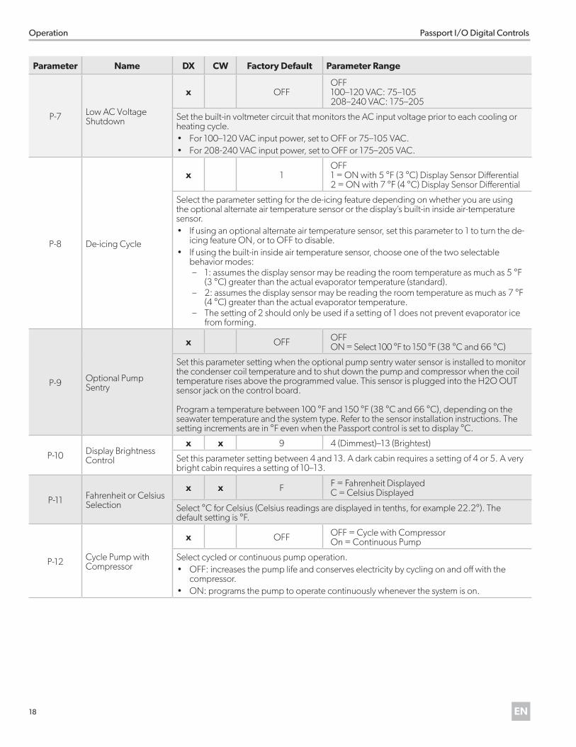
Parameter Name DX CW Factory Default Parameter Range
P-7 Low AC Voltage Shutdown
x OFFOFF100–120 VAC: 75–105208–240 VAC: 175–205
Set the built-in voltmeter circuit that monitors the AC input voltage prior to each cooling or heating cycle. • For 100–120 VAC input power, set to OFF or 75–105 VAC.• For 208-240 VAC input power, set to OFF or 175–205 VAC.
P-8 De-icing Cycle
x 1OFF1 = ON with 5 °F (3 °C) Display Sensor Differential2 = ON with 7 °F (4 °C) Display Sensor Differential
Select the parameter setting for the de-icing feature depending on whether you are using the optional alternate air temperature sensor or the display’s built-in inside air-temperature sensor. • If using an optional alternate air temperature sensor, set this parameter to 1 to turn the de-
icing feature ON, or to OFF to disable. • If using the built-in inside air temperature sensor, choose one of the two selectable
behavior modes: – 1: assumes the display sensor may be reading the room temperature as much as 5 °F
(3 °C) greater than the actual evaporator temperature (standard). – 2: assumes the display sensor may be reading the room temperature as much as 7 °F
(4 °C) greater than the actual evaporator temperature. – The setting of 2 should only be used if a setting of 1 does not prevent evaporator ice
from forming.
P-9 Optional Pump Sentry
x OFF OFFON = Select 100 °F to 150 °F (38 °C and 66 °C)
Set this parameter setting when the optional pump sentry water sensor is installed to monitor the condenser coil temperature and to shut down the pump and compressor when the coil temperature rises above the programmed value. This sensor is plugged into the H2O OUT sensor jack on the control board.
Program a temperature between 100 °F and 150 °F (38 °C and 66 °C), depending on the seawater temperature and the system type. Refer to the sensor installation instructions. The setting increments are in °F even when the Passport control is set to display °C.
P-10 Display Brightness Control
x x 9 4 (Dimmest)–13 (Brightest)
Set this parameter setting between 4 and 13. A dark cabin requires a setting of 4 or 5. A very bright cabin requires a setting of 10–13.
P-11 Fahrenheit or Celsius Selection
x x F F = Fahrenheit DisplayedC = Celsius Displayed
Select °C for Celsius (Celsius readings are displayed in tenths, for example 22.2°). The default setting is °F.
P-12 Cycle Pump with Compressor
x OFF OFF = Cycle with CompressorOn = Continuous Pump
Select cycled or continuous pump operation. • OFF: increases the pump life and conserves electricity by cycling on and off with the
compressor. • ON: programs the pump to operate continuously whenever the system is on.
19EN
Passport I/O Digital Controls Operation
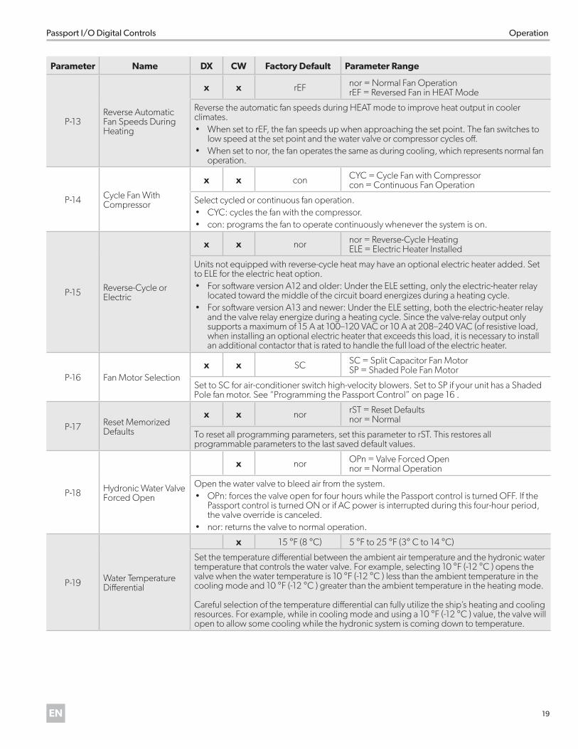
Parameter Name DX CW Factory Default Parameter Range
P-13Reverse Automatic Fan Speeds During Heating
x x rEF nor = Normal Fan OperationrEF = Reversed Fan in HEAT Mode
Reverse the automatic fan speeds during HEAT mode to improve heat output in cooler climates. • When set to rEF, the fan speeds up when approaching the set point. The fan switches to
low speed at the set point and the water valve or compressor cycles off.• When set to nor, the fan operates the same as during cooling, which represents normal fan
operation.
P-14 Cycle Fan With Compressor
x x con CYC = Cycle Fan with Compressorcon = Continuous Fan Operation
Select cycled or continuous fan operation.• CYC: cycles the fan with the compressor. • con: programs the fan to operate continuously whenever the system is on.
P-15 Reverse-Cycle or Electric
x x nor nor = Reverse-Cycle HeatingELE = Electric Heater Installed
Units not equipped with reverse-cycle heat may have an optional electric heater added. Set to ELE for the electric heat option.• For software version A12 and older: Under the ELE setting, only the electric-heater relay
located toward the middle of the circuit board energizes during a heating cycle.• For software version A13 and newer: Under the ELE setting, both the electric-heater relay
and the valve relay energize during a heating cycle. Since the valve-relay output only supports a maximum of 15 A at 100–120 VAC or 10 A at 208–240 VAC (of resistive load, when installing an optional electric heater that exceeds this load, it is necessary to install an additional contactor that is rated to handle the full load of the electric heater.
P-16 Fan Motor Selectionx x SC SC = Split Capacitor Fan Motor
SP = Shaded Pole Fan Motor
Set to SC for air-conditioner switch high-velocity blowers. Set to SP if your unit has a Shaded Pole fan motor. See “Programming the Passport Control” on page 16 .
P-17 Reset Memorized Defaults
x x nor rST = Reset Defaultsnor = Normal
To reset all programming parameters, set this parameter to rST. This restores all programmable parameters to the last saved default values.
P-18 Hydronic Water Valve Forced Open
x nor OPn = Valve Forced Opennor = Normal Operation
Open the water valve to bleed air from the system. • OPn: forces the valve open for four hours while the Passport control is turned OFF. If the
Passport control is turned ON or if AC power is interrupted during this four-hour period, the valve override is canceled.
• nor: returns the valve to normal operation.
P-19 Water Temperature Differential
x 15 °F (8 °C) 5 °F to 25 °F (3° C to 14 °C)
Set the temperature differential between the ambient air temperature and the hydronic water temperature that controls the water valve. For example, selecting 10 °F (-12 °C ) opens the valve when the water temperature is 10 °F (-12 °C ) less than the ambient temperature in the cooling mode and 10 °F (-12 °C ) greater than the ambient temperature in the heating mode.
Careful selection of the temperature differential can fully utilize the ship’s heating and cooling resources. For example, while in cooling mode and using a 10 °F (-12 °C ) value, the valve will open to allow some cooling while the hydronic system is coming down to temperature.
20 EN
Operation Passport I/O Digital Controls
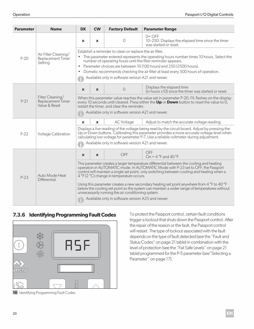
Parameter Name DX CW Factory Default Parameter Range
P-20Air Filter Cleaning/Replacement Timer Setting
x x 00= OFF10–250: Displays the elapsed time since the timer was started or reset.
Establish a reminder to clean or replace the air filter. • The parameter entered represents the operating hours number times 10 hours. Select the
number of operating hours until the filter reminder appears. • Parameter choices are between 10 (100 hours) and 250 (2500 hours). • Dometic recommends checking the air filter at least every 500 hours of operation.
IAvailable only in software version A21 and newer.
P-21Filter Cleaning/Replacement Timer Value & Reset
x x 0 Displays the elapsed time (in hours x10) since the timer was started or reset.
When this parameter value reaches the value set in parameter P-20, FIL flashes on the display every 10 seconds until cleared. Press either the Up or Down button to reset the value to 0, restart the timer, and clear the reminder.
IAvailable only in software version A21 and newer.
P-22 Voltage Calibration
x x AC Voltage Adjust to match the accurate voltage reading.
Displays a live reading of the voltage being read by the circuit board. Adjust by pressing the Up or Down buttons. Calibrating this parameter provides a more accurate voltage level when calculating low voltage for parameter P-7. Use a reliable voltmeter during adjustment.
IAvailable only in software version A21 and newer.
P-23 Auto Mode Heat Differential
x x OFF OFFOn = 4 °F and 40 °F
This parameter creates a larger temperature differential between the cooling and heating operation in AUTOMATIC mode. In AUTOMATIC Mode with P-23 set to OFF, the Passport control will maintain a single set point, only switching between cooling and heating when a 4 °F (2 °C) change in temperature occurs.
Using this parameter creates a new secondary heating set point anywhere from 4 °F to 40 °F below the cooling set point so the system can maintain a wider range of temperatures without unnecessarily running the air conditioning system.
IAvailable only in software version A25 and newer.
7 .3 .6 Identifying Programming Fault Codes
10 Identifying Programming Fault Codes
To protect the Passport control, certain fault conditions trigger a lockout that shuts down the Passport control. After the repair of the reason or the fault, the Passport control will restart. The type of lockout associated with the fault depends on the type of fault detected (see the “Fault and Status Codes” on page 21 table) in combination with the level of protection (see the “Fail Safe Levels” on page 21 table) programmed for the P-5 parameter (see”Selecting a Parameter” on page 17).
21EN
Passport I/O Digital Controls Operation
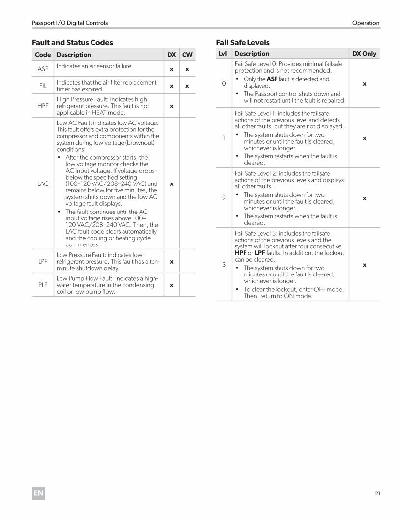
Fault and Status Codes
Code Description DX CW
ASF Indicates an air sensor failure. x x
FIL Indicates that the air filter replacement timer has expired. x x
HPFHigh Pressure Fault: indicates high refrigerant pressure. This fault is not applicable in HEAT mode.
x
LAC
Low AC Fault: indicates low AC voltage. This fault offers extra protection for the compressor and components within the system during low-voltage (brownout) conditions:• After the compressor starts, the
low voltage monitor checks the AC input voltage. If voltage drops below the specified setting (100–120 VAC/208–240 VAC) and remains below for five minutes, the system shuts down and the low AC voltage fault displays.
• The fault continues until the AC input voltage rises above 100–120 VAC/208–240 VAC. Then, the LAC fault code clears automatically and the cooling or heating cycle commences.
x
LPFLow Pressure Fault: indicates low refrigerant pressure. This fault has a ten-minute shutdown delay.
x
PLFLow Pump Flow Fault: indicates a high-water temperature in the condensing coil or low pump flow.
x
Fail Safe LevelsLvl Description DX Only
0
Fail Safe Level 0: Provides minimal failsafe protection and is not recommended. • Only the ASF fault is detected and
displayed. • The Passport control shuts down and
will not restart until the fault is repaired.
x
1
Fail Safe Level 1: includes the failsafe actions of the previous level and detects all other faults, but they are not displayed. • The system shuts down for two
minutes or until the fault is cleared, whichever is longer.
• The system restarts when the fault is cleared.
x
2
Fail Safe Level 2: includes the failsafe actions of the previous levels and displays all other faults.• The system shuts down for two
minutes or until the fault is cleared, whichever is longer.
• The system restarts when the fault is cleared.
x
3
Fail Safe Level 3: includes the failsafe actions of the previous levels and the system will lockout after four consecutive HPF or LPF faults. In addition, the lockout can be cleared. • The system shuts down for two
minutes or until the fault is cleared, whichever is longer.
• To clear the lockout, enter OFF mode. Then, return to ON mode.
x
22 EN
Operation Passport I/O Digital Controls
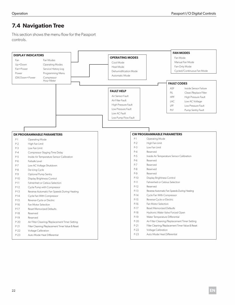
7 .4 Navigation TreeThis section shows the menu flow for the Passport controls.
OPERATING MODES
Cool Mode
Heat Mode
Dehumidification Mode
Automatic Mode
FAN MODES
Fan Mode
Manual Fan Mode
Fan-Only Mode
Cycled/Continuous Fan Mode
FAULT CODES
ASF Inside Sensor Failure
FIL Clean/Replace Filter
HPF High Pressure Fault
LAC Low AC Voltage
LPF Low Pressure Fault
PLF Pump Sentry Fault
FAULT HELP
Air Sensor Fault
Air Filter Fault
High Pressure Fault
Low Pressure Fault
Low AC Fault
Low Pump Flow Fault
DX PROGRAMMABLE PARAMETERS
P-1 Operating Mode
P-2 High Fan Limit
P-3 Low Fan Limit
P-4 Compressor Staging Time Delay
P-5 Inside Air Temperature Sensor Calibration
P-6 Failsafe Level
P-7 Low AC Voltage Shutdown
P-8 De-icing Cycle
P-9 Optional Pump Sentry
P-10 Display Brightness Control
P-11 Fahrenheit or Celsius Selection
P-12 Cycle Pump with Compressor
P-13 Reverse Automatic Fan Speeds During Heating
P-14 Cycle Fan With Compressor
P-15 Reverse-Cycle or Electric
P-16 Fan Motor Selection
P-17 Reset Memorized Defaults
P-18 Reserved
P-19 Reserved
P-20 Air Filter Cleaning/Replacement Timer Setting
P-21 Filter Cleaning/Replacement Timer Value & Reset
P-22 Voltage Calibration
P-23 Auto Mode Heat Differential
CW PROGRAMMABLE PARAMETERSP-1 Operating Mode
P-2 High Fan Limit
P-3 Low Fan Limit
P-4 Reserved
P-5 Inside Air Temperature Sensor Calibration
P-6 Reserved
P-7 Reserved
P-8 Reserved
P-9 Reserved
P-10 Display Brightness Control
P-11 Fahrenheit or Celsius Selection
P-12 Reserved
P-13 Reverse Automatic Fan Speeds During Heating
P-14 Cycle Fan With Compressor
P-15 Reverse-Cycle or Electric
P-16 Fan Motor Selection
P-17 Reset Memorized Defaults
P-18 Hydronic Water Valve Forced Open
P-19 Water Temperature Differential
P-20 Air Filter Cleaning/Replacement Timer Setting
P-21 Filter Cleaning/Replacement Timer Value & Reset
P-22 Voltage Calibration
P-23 Auto Mode Heat Differential
DISPLAY INDICATORS
Fan Fan Modes
Up+Down Operating Modes
Fan+Power Service History Log
Power Programming Menu
(DX) Down+Power Compressor Hour Meter
23EN
Passport I/O Digital Controls Maintenance
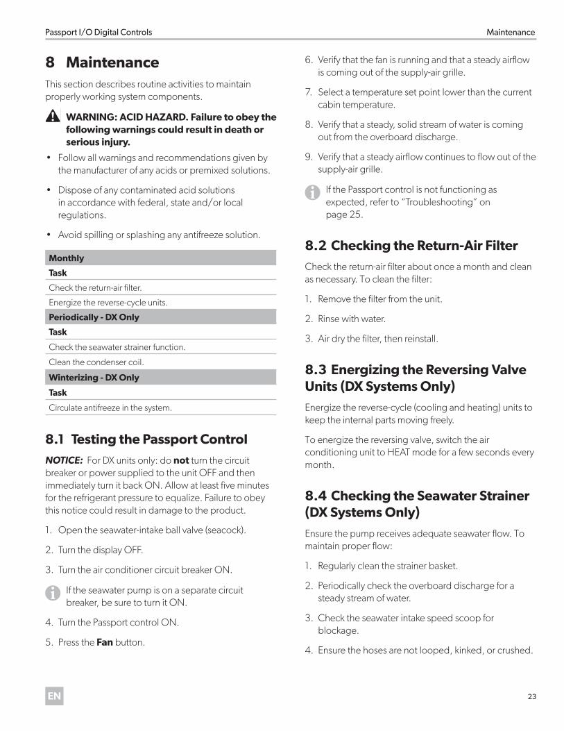
8 MaintenanceThis section describes routine activities to maintain properly working system components.
�WARNING: ACID HAZARD . Failure to obey the following warnings could result in death or serious injury .
• Follow all warnings and recommendations given by the manufacturer of any acids or premixed solutions.
• Dispose of any contaminated acid solutions in accordance with federal, state and/or local regulations.
• Avoid spilling or splashing any antifreeze solution.
Monthly
Task
Check the return-air filter.
Energize the reverse-cycle units.
Periodically - DX Only
Task
Check the seawater strainer function.
Clean the condenser coil.
Winterizing - DX Only
Task
Circulate antifreeze in the system.
8 .1 Testing the Passport ControlNOTICE: For DX units only: do not turn the circuit breaker or power supplied to the unit OFF and then immediately turn it back ON. Allow at least five minutes for the refrigerant pressure to equalize. Failure to obey this notice could result in damage to the product.
1. Open the seawater-intake ball valve (seacock).
2. Turn the display OFF.
3. Turn the air conditioner circuit breaker ON.
I If the seawater pump is on a separate circuit breaker, be sure to turn it ON.
4. Turn the Passport control ON.
5. Press the Fan button.
6. Verify that the fan is running and that a steady airflow is coming out of the supply-air grille.
7. Select a temperature set point lower than the current cabin temperature.
8. Verify that a steady, solid stream of water is coming out from the overboard discharge.
9. Verify that a steady airflow continues to flow out of the supply-air grille.
I If the Passport control is not functioning as expected, refer to “Troubleshooting” on page 25.
8 .2 Checking the Return-Air FilterCheck the return-air filter about once a month and clean as necessary. To clean the filter:
1. Remove the filter from the unit.
2. Rinse with water.
3. Air dry the filter, then reinstall.
8 .3 Energizing the Reversing Valve Units (DX Systems Only)Energize the reverse-cycle (cooling and heating) units to keep the internal parts moving freely.
To energize the reversing valve, switch the air conditioning unit to HEAT mode for a few seconds every month.
8 .4 Checking the Seawater Strainer (DX Systems Only)Ensure the pump receives adequate seawater flow. To maintain proper flow:
1. Regularly clean the strainer basket.
2. Periodically check the overboard discharge for a steady stream of water.
3. Check the seawater intake speed scoop for blockage.
4. Ensure the hoses are not looped, kinked, or crushed.
24 EN
Maintenance Passport I/O Digital Controls
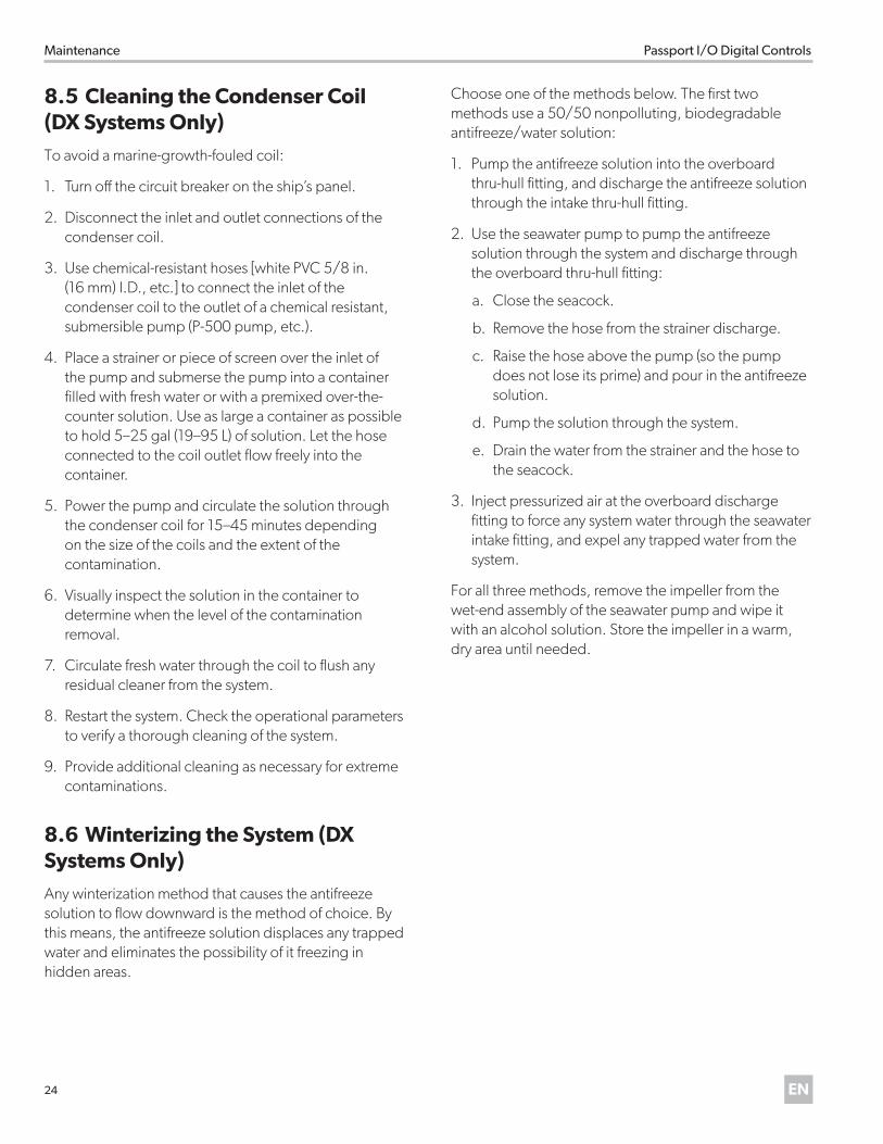
8 .5 Cleaning the Condenser Coil (DX Systems Only)To avoid a marine-growth-fouled coil:
1. Turn off the circuit breaker on the ship’s panel.
2. Disconnect the inlet and outlet connections of the condenser coil.
3. Use chemical-resistant hoses [white PVC 5/8 in. (16 mm) I.D., etc.] to connect the inlet of the condenser coil to the outlet of a chemical resistant, submersible pump (P-500 pump, etc.).
4. Place a strainer or piece of screen over the inlet of the pump and submerse the pump into a container filled with fresh water or with a premixed over-the-counter solution. Use as large a container as possible to hold 5–25 gal (19–95 L) of solution. Let the hose connected to the coil outlet flow freely into the container.
5. Power the pump and circulate the solution through the condenser coil for 15–45 minutes depending on the size of the coils and the extent of the contamination.
6. Visually inspect the solution in the container to determine when the level of the contamination removal.
7. Circulate fresh water through the coil to flush any residual cleaner from the system.
8. Restart the system. Check the operational parameters to verify a thorough cleaning of the system.
9. Provide additional cleaning as necessary for extreme contaminations.
8 .6 Winterizing the System (DX Systems Only)Any winterization method that causes the antifreeze solution to flow downward is the method of choice. By this means, the antifreeze solution displaces any trapped water and eliminates the possibility of it freezing in hidden areas.
Choose one of the methods below. The first two methods use a 50/50 nonpolluting, biodegradable antifreeze/water solution:
1. Pump the antifreeze solution into the overboard thru-hull fitting, and discharge the antifreeze solution through the intake thru-hull fitting.
2. Use the seawater pump to pump the antifreeze solution through the system and discharge through the overboard thru-hull fitting:
a. Close the seacock.
b. Remove the hose from the strainer discharge.
c. Raise the hose above the pump (so the pump does not lose its prime) and pour in the antifreeze solution.
d. Pump the solution through the system.
e. Drain the water from the strainer and the hose to the seacock.
3. Inject pressurized air at the overboard discharge fitting to force any system water through the seawater intake fitting, and expel any trapped water from the system.
For all three methods, remove the impeller from the wet-end assembly of the seawater pump and wipe it with an alcohol solution. Store the impeller in a warm, dry area until needed.
25EN
Passport I/O Digital Controls Troubleshooting
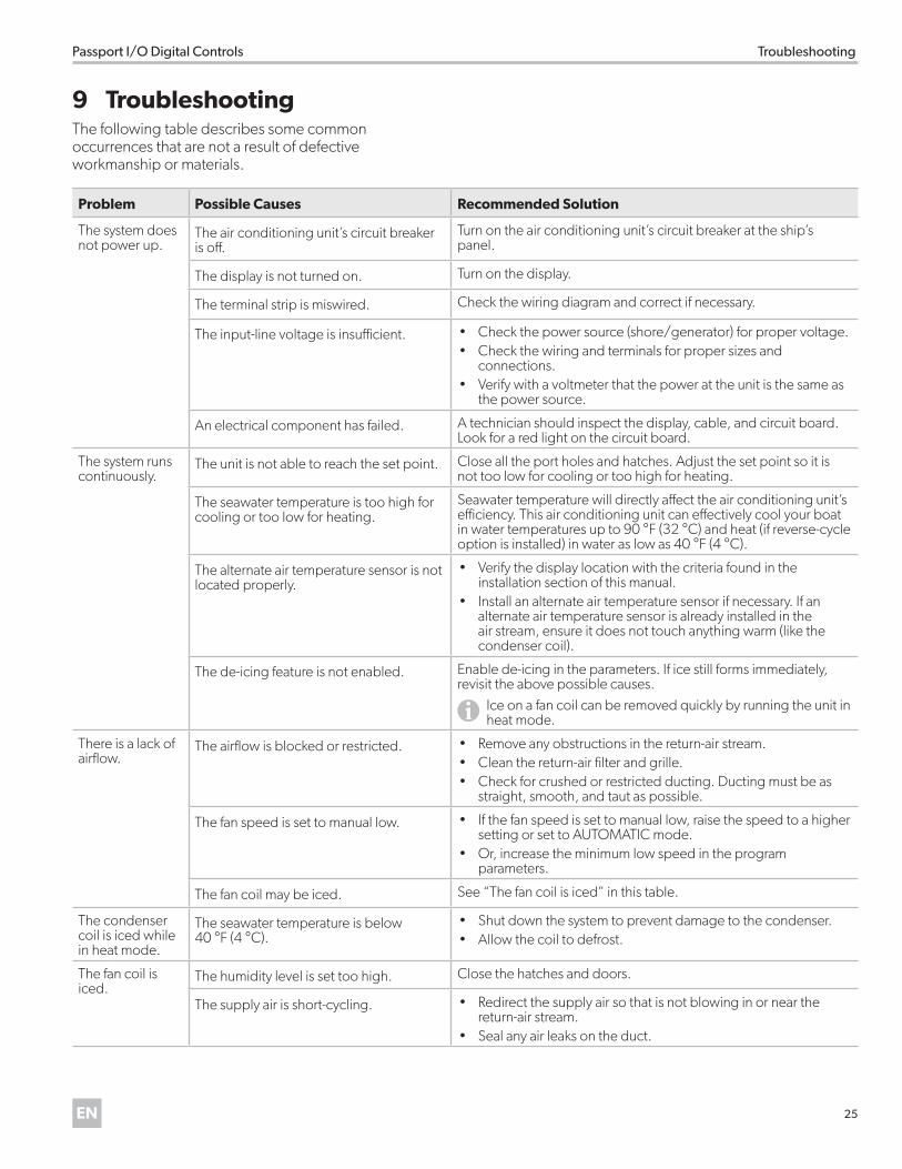
9 TroubleshootingThe following table describes some common occurrences that are not a result of defective workmanship or materials.
Problem Possible Causes Recommended Solution
The system does not power up.
The air conditioning unit’s circuit breaker is off.
Turn on the air conditioning unit’s circuit breaker at the ship’s panel.
The display is not turned on. Turn on the display.
The terminal strip is miswired. Check the wiring diagram and correct if necessary.
The input-line voltage is insufficient. • Check the power source (shore/generator) for proper voltage. • Check the wiring and terminals for proper sizes and
connections. • Verify with a voltmeter that the power at the unit is the same as
the power source.
An electrical component has failed. A technician should inspect the display, cable, and circuit board. Look for a red light on the circuit board.
The system runs continuously.
The unit is not able to reach the set point. Close all the port holes and hatches. Adjust the set point so it is not too low for cooling or too high for heating.
The seawater temperature is too high for cooling or too low for heating.
Seawater temperature will directly affect the air conditioning unit’s efficiency. This air conditioning unit can effectively cool your boat in water temperatures up to 90 °F (32 °C) and heat (if reverse-cycle option is installed) in water as low as 40 °F (4 °C).
The alternate air temperature sensor is not located properly.
• Verify the display location with the criteria found in the installation section of this manual.
• Install an alternate air temperature sensor if necessary. If an alternate air temperature sensor is already installed in the air stream, ensure it does not touch anything warm (like the condenser coil).
The de-icing feature is not enabled. Enable de-icing in the parameters. If ice still forms immediately, revisit the above possible causes.
IIce on a fan coil can be removed quickly by running the unit in heat mode.
There is a lack of airflow.
The airflow is blocked or restricted. • Remove any obstructions in the return-air stream.• Clean the return-air filter and grille. • Check for crushed or restricted ducting. Ducting must be as
straight, smooth, and taut as possible.
The fan speed is set to manual low. • If the fan speed is set to manual low, raise the speed to a higher setting or set to AUTOMATIC mode.
• Or, increase the minimum low speed in the program parameters.
The fan coil may be iced. See “The fan coil is iced” in this table.
The condenser coil is iced while in heat mode.
The seawater temperature is below 40 °F (4 °C).
• Shut down the system to prevent damage to the condenser. • Allow the coil to defrost.
The fan coil is iced.
The humidity level is set too high. Close the hatches and doors.
The supply air is short-cycling. • Redirect the supply air so that is not blowing in or near the return-air stream.
• Seal any air leaks on the duct.
26 EN
Troubleshooting Passport I/O Digital Controls
Problem Possible Causes Recommended Solution
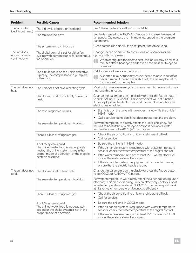
The fan coil is iced. (continued)
The airflow is blocked or restricted See “There is a lack of airflow” in this table.
The fan runs too slow. Set the fan speed to AUTOMATIC mode or increase the manual fan speed. Or, increase the minimum low speed in the program parameters.
The system runs continuously. Close hatches and doors, raise set point, turn on de-icing.
The fan does not run or runs continuously.
The digital control is set for either fan cycling with compressor or for continuous fan operation.
Change the fan operation to continuous fan operation or fan cycling with compressor.
IWhen configured for electric heat, the fan will stay on for four minutes after a heat cycle ends even if the fan is set to cycled operation.
The circuit board on the unit is defective. Typically, the compressor and pump are still running.
Call for service to replace the board.
IA shorted relay or triac may cause the fan to never shut off or never turn on. If the fan never shuts off, the fan may be set to ‘continuous’ on the display.
The unit does not heat.
The unit does not have a heating cycle. Most units have a reverse cycle to create heat, but some units may not have this function.
The display is set to cool-only or electric heat.
Change the parameters on the display or press the Mode button to set HEAT or AUTOMATIC. The electric heat will not function if the display is set to electric heat and the unit does not have an electric heater added.
The reversing valve is stuck. • Lightly tap on the valve with a rubber mallet while the unit is in HEAT mode.
• Call a service technician if that does not correct the problem.
The seawater temperature is too low. Seawater temperature directly affects the unit’s efficiency. For the unit to heat (if the reverse-cycle option is available), water temperatures must be 40 °F (4 °C) or higher.
There is a loss of refrigerant gas. • Check the air conditioning unit for a refrigerant oil leak.• Call for service.
(For CW systems only) The chilled-water loop is inadequately heated, the chiller system is not in the proper mode of operation, or the electric heater is disabled.
• Be sure the chiller is in HEAT mode. • If the air handler system is equipped with water-temperature
sensors, check the water temperature at the digital control. • If the water temperature is not at least 15 °F warmer for HEAT
mode, the water valve will not open. • If the air handler system is equipped with an electric heater,
ensure that the electric heat is enabled.
The unit does not cool.
The display is set to heat-only. Change the parameters on the display or press the Mode button to set COOL or AUTOMATIC mode.
The seawater temperature is too high. Seawater temperature will directly affect the air conditioning unit’s efficiency. This air conditioning unit can effectively cool your boat in water temperatures up to 90 °F (32 °C). The unit may still work at higher water temperatures, but not as efficiently.
There is a loss of refrigerant gas. • Check the air conditioning unit for a refrigerant oil leak.• Call for service.
(For CW systems only) The chilled-water loop is inadequately cooled or the chiller system is not in the proper mode of operation.
• Be sure the chiller is in COOL mode. • If the air handler system is equipped with water-temperature
sensors, check the water temperature at the digital control. • If the water temperature is not at least 15 °F cooler for COOL
mode, the water valve will not open.
27EN
Passport I/O Digital Controls Troubleshooting
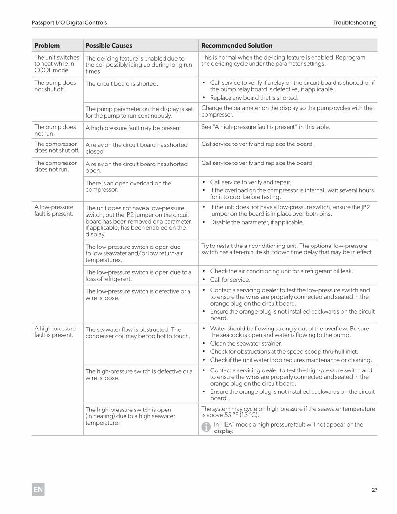
Problem Possible Causes Recommended Solution
The unit switches to heat while in COOL mode.
The de-icing feature is enabled due to the coil possibly icing up during long run times.
This is normal when the de-icing feature is enabled. Reprogram the de-icing cycle under the parameter settings.
The pump does not shut off.
The circuit board is shorted. • Call service to verify if a relay on the circuit board is shorted or if the pump relay board is defective, if applicable.
• Replace any board that is shorted.
The pump parameter on the display is set for the pump to run continuously.
Change the parameter on the display so the pump cycles with the compressor.
The pump does not run.
A high-pressure fault may be present. See “A high-pressure fault is present” in this table.
The compressor does not shut off.
A relay on the circuit board has shorted closed.
Call service to verify and replace the board.
The compressor does not run.
A relay on the circuit board has shorted open.
Call service to verify and replace the board.
There is an open overload on the compressor.
• Call service to verify and repair. • If the overload on the compressor is internal, wait several hours
for it to cool before testing.
A low-pressure fault is present.
The unit does not have a low-pressure switch, but the JP2 jumper on the circuit board has been removed or a parameter, if applicable, has been enabled on the display.
• If the unit does not have a low-pressure switch, ensure the JP2 jumper on the board is in place over both pins.
• Disable the parameter, if applicable.
The low-pressure switch is open due to low seawater and/or low return-air temperatures.
Try to restart the air conditioning unit. The optional low-pressure switch has a ten-minute shutdown time delay that may be in effect.
The low-pressure switch is open due to a loss of refrigerant.
• Check the air conditioning unit for a refrigerant oil leak.• Call for service.
The low-pressure switch is defective or a wire is loose.
• Contact a servicing dealer to test the low-pressure switch and to ensure the wires are properly connected and seated in the orange plug on the circuit board.
• Ensure the orange plug is not installed backwards on the circuit board.
A high-pressure fault is present.
The seawater flow is obstructed. The condenser coil may be too hot to touch.
• Water should be flowing strongly out of the overflow. Be sure the seacock is open and water is flowing to the pump.
• Clean the seawater strainer. • Check for obstructions at the speed scoop thru-hull inlet. • Check if the unit water loop requires maintenance or cleaning.
The high-pressure switch is defective or a wire is loose.
• Contact a servicing dealer to test the high-pressure switch and to ensure the wires are properly connected and seated in the orange plug on the circuit board.
• Ensure the orange plug is not installed backwards on the circuit board.
The high-pressure switch is open (in heating) due to a high seawater temperature.
The system may cycle on high-pressure if the seawater temperature is above 55 °F (13 °C).
IIn HEAT mode a high pressure fault will not appear on the display.
28 EN
Troubleshooting Passport I/O Digital Controls
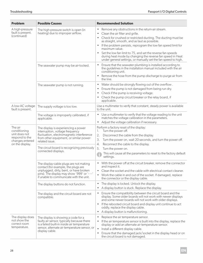
Problem Possible Causes Recommended Solution
A high-pressure fault is present.(continued)
The high-pressure switch is open (in heating) due to improper airflow.
• Remove any obstructions in the return-air stream. • Clean the air filter and grille. • Check for crushed or restricted ducting. The ducting must be
as straight, smooth, and as taut as possible.• If the problem persists, reprogram the low fan speed limit for
maximum value. • Set the low fan limit to 75, and set the reverse fan speeds
during heat mode by changing the reverse fan speed in Heat under general settings, or manually set the fan speed to high.
The seawater pump may be air-locked. • Ensure that the seawater plumbing is installed according to the guidelines in the installation manual included with the air conditioning unit.
• Remove the hose from the pump discharge to purge air from the line.
The seawater pump is not running. • Water should be strongly flowing out of the overflow . • Ensure the pump is not damaged from being run dry. • Check if the pump is receiving voltage. • Check the pump circuit breaker or the relay board, if
applicable.
A low-AC voltage fault is present.
The supply voltage is too low. Use a multimeter to verify that constant, steady power is available to the unit.
The voltage is improperly calibrated, if applicable.
• Use a multimeter to verify that the voltage reading to the unit matches the voltage calibration in the parameters.
• Adjust the voltage calibration if necessary.
The air conditioning unit does not respond to the changes entered on the display.
The display is experiencing a power interruption, voltage frequency fluctuation, electromagnetic interference from other equipment, or similar power-related issue.
Perform a factory reset of the display:1. Turn the power off.2. Disconnect the cable from the display.3. Turn the power on, wait 20 seconds, and turn the power off.4. Reconnect the cable to the display.5. Turn the power on.
IThis will cause all the parameters to reset to the factory default settings.
The circuit board is recognizing previously connected displays.
The display-cable plugs are not making contact (for example, the plugs are unplugged, dirty, bent, or have broken pins). The display may show ‘999’ or ‘- - -‘ if unable to communicate with the unit.
• With the power off at the circuit breaker, remove the connector and inspect it.
• Clean the socket and the cable with electrical contact cleaner. • Work the cable in and out of the socket. If damaged, replace
the connector or the display cable.
The display buttons do not function. • The display is locked. Unlock the display. • A display button is stuck. Replace the display.
The display and the circuit board are not compatible.
• Ensure the compatibility between the circuit board and the display. Some older boards will not work with newer displays and some newer boards will not work with older displays.
• If the rebooted circuit board and display unit continue to act oddly, replace the display cable.
• A display button is malfunctioning.
The display does not show the correct room temperature.
The display is showing a code for a faulty air sensor, typically because there is a failed built-in inside air temperature sensor, alternate air temperature sensor, or display cable.
• Replace the air temperature sensor. • If the air temperature sensor is built into the display, replace the
display or add an alternate air temperature sensor. • Install a different display cable. • Ensure that the damaged jack/socket in the display head or on
the circuit board is not damaged.
29EN
Passport I/O Digital Controls Disposal
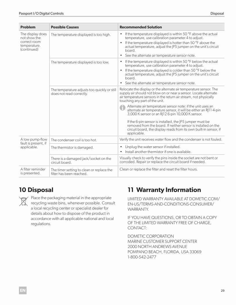
Problem Possible Causes Recommended Solution
The display does not show the correct room temperature. (continued)
The temperature displayed is too high. • If the temperature displayed is within 50 °F above the actual temperature, use calibration parameter 4 to adjust.
• If the temperature displayed is hotter than 50 °F above the actual temperature, adjust the JP5 jumper on the unit’s circuit board.
• See the alternate air temperature sensor note.
The temperature displayed is too low. • If the temperature displayed is within 50 °F below the actual temperature, use calibration parameter 4 to adjust.
• If the temperature displayed is colder than 50 °F below the actual temperature, adjust the JP5 jumper on the unit’s circuit board.
• See the alternate air temperature sensor note.
The temperature adjusts too quickly or still does not read correctly.
Relocate the display or the alternate air temperature sensor. The supply air should not blow on or near a sensor. Locate alternate air temperature sensors in the return air stream, not physically touching any part of the unit.
IAlternate air temperature sensor note: if the unit uses an alternate air temperature sensor, it will be either an RJ11 4-pin 3,000 K sensor or an RJ12 6-pin 10,000 K sensor. If the 6-pin sensor is installed, the JP5 jumper must be removed from the board. If neither sensor is installed on the circuit board, the display reads from its own built-in sensor, if applicable.
A low pump-flow fault is present, if applicable.
The condenser coil is too hot. Verify the unit receives water flow and the condenser is not fouled.
The thermistor is damaged. • Unplug the water sensor if installed.• Install another thermistor if one is available.
There is a damaged jack/socket on the circuit board.
Visually check to verify the pins inside the socket are not bent or corroded. Repair or replace the circuit board if needed.
A filter reminder is presented.
The timer setting to clean or replace the filter has been reached.
Clean or replace the filter and reset the filter hours.
10 Disposal
MPlace the packaging material in the appropriate recycling waste bins, whenever possible. Consult a local recycling center or specialist dealer for details about how to dispose of the product in accordance with all applicable national and local regulations.
11 Warranty InformationLIMITED WARRANTY AVAILABLE AT DOMETIC.COM/EN-US/TERMS-AND-CONDITIONS-CONSUMER/WARRANTY.
IF YOU HAVE QUESTIONS, OR TO OBTAIN A COPY OF THE LIMITED WARRANTY FREE OF CHARGE, CONTACT:
DOMETIC CORPORATION MARINE CUSTOMER SUPPORT CENTER 2000 NORTH ANDREWS AVENUE POMPANO BEACH, FLORIDA, USA 33069 1-800-542-2477

30 EN
Passport I/O Digital Controls

31EN
Passport I/O Digital Controls

Mobile living made easy.
A complete list of Dometic companies, which comprise the Dometic Group, can be found in the public filings of:DOMETIC GROUP AB Hemvärnsgatan 15 SE-17154 Solna Sweden
CONTACT US dometic .com/en-us/terms-and-conditions-consumer/contact-us
dometic .com