Embed Size (px)
Citation preview
Operation manual
3W Modellmotoren GmbH, Hasswiesenstrasse 22, 63322 Rödermark
www.3w-modellmotoren.de
© Copyright Qualitätsmanagement 3W, Revision 2, Pag e 1 from 19, valid from 22.02.2013
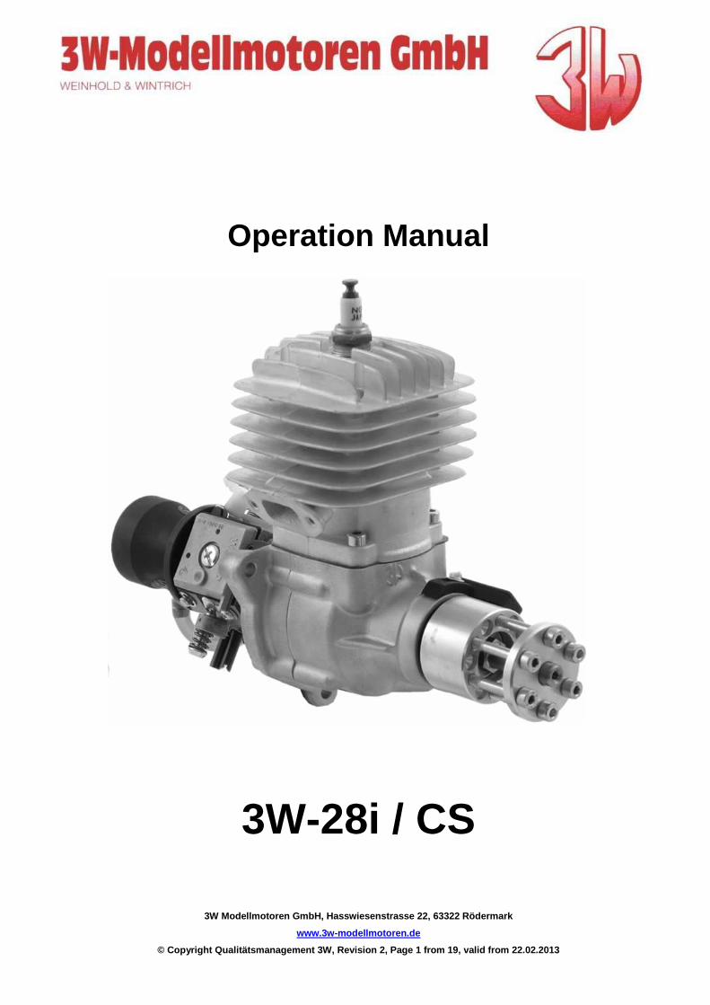
Operation Manual
3W-28i / CS
Operation manual
3W Modellmotoren GmbH, Hasswiesenstrasse 22, 63322 Rödermark
www.3w-modellmotoren.de
© Copyright Qualitätsmanagement 3W, Revision 2, Pag e 2 from 19, valid from 22.02.2013
Dear customer, Thank you for placing your confidence in 3W. Our long experience (since 1985) in designing and producing model airplane engines, ranging from single up to six cylinder, has been utilized to provide you with the best engine possible. Our in-house engineer has been designing two and four stroke engines for gasoline and diesel for 38 years. We are continually looking at new technologies and working on new designs. Please be assured that we at 3W always strive to provide you with engines that are state of the art.
You can count on your 3W engine to have:
• a high level of precision • high torque in the low rpm range • excellent running characteristics • a long life • lots of power • And a 36 month conditional warranty. The product range of this engine includes the follwoing types:
direction of rotation
modelrange: View to propeller : Art. Nr.:
We wish you plenty of fun and success with your new 3W engine. Sincerely, The 3W Team
3W-28i (57.000/00) Counterclockwise 10.000.200
3W-28i (57.000/00) Clockwise 10.000.201
3W-28i CS Counterclockwise 10.000.210
3W-28i CS Clockwise 10.000.211
Operation manual
3W Modellmotoren GmbH, Hasswiesenstrasse 22, 63322 Rödermark
www.3w-modellmotoren.de
© Copyright Qualitätsmanagement 3W, Revision 2, Pag e 3 from 19, valid from 22.02.2013
Limited Warranty We grant a 36 month warranty from the date of purchase or 1200 operating hours. This warranty is limited to the replacement of defective parts that are a direct result of faulty material or manufacturing. No claim concerning a defect caused by non-compliance with installation or operation instructions, mishandling, unsuitable spare parts nor unskilled repairs will be acknowledged. Please ask your dealer to fill out a warranty certificate for you at the time of purchase. Important: Keep this certificate in a safe place as this warranty will not be honored without it. The original receipt is also required. Warranty terminates if unauthorised modifications are done.
The safe operation of the engine is our primary con cern. Therefore any alteration, modification or addition to the engine is not recommended and wi ll void your warranty immediately.
In case of defect during the period of garantee, return this product to your nearest 3W-Dealer or to 3W -Germany direct, at your costs. The garantee is limited to the value of the product. The guarantee does not cover any damage caused by misuse or neglect, accidents, abrasion, exposure to extreme temperatures, solvents, acids, water, normal wear and tear or damage by common carrier.
Warning!
This engine is not a toy! Serious injury and /or de ath can occur from its misuse! READ and become familiar with this entire instruction manual . LEARN the engine's applications, limitations, and possible hazards.
When working on the engine(s) it is strictly prohib ited to block the piston respectivly crankshaft from moving by using a tool touching / h itting the piston crown / top.
Reason: Distortion of the crown / top where the tool touches / hits the piston, material structure will be changed as well as the outside diameter / conture of the piston.
What could happen: Hole in the piston and / or piston will size after a running time which cannot be determind. To block the crankshaft and / or piston from moving a tool has to be used clamping the propeller hub only.
Only use 3W mufflers or 3 W-model engines GmbH licensed third-party product s. For operation of 3W engines Only original 3W igniti ons
be allowed to use. Otherwise there is warranty loss.
Operation manual
3W Modellmotoren GmbH, Hasswiesenstrasse 22, 63322 Rödermark
www.3w-modellmotoren.de
© Copyright Qualitätsmanagement 3W, Revision 2, Pag e 4 from 19, valid from 22.02.2013
Important! For your safety and for the safety of those around you -- also to learn what is required to maintain your warranty - we strongly advise you to read this entire manual carefully BEFORE you start using the engine. Safe Operation and 3W's Conditional Warranty For safe operation and to maintain your warranty you must: • Have a properly designed engine box on your model • Mount the engine correctly • Provide adequate air flow and cooling for the engine • Provide adequate air flow and cooling for the exhaust • Use an approved propeller and spinner • Drill the propeller correctly • Balance the propeller correctly • Tighten the propeller bolts correctly and check them regularly • Properly mount your ignition to avoid overheating • Use the correct battery and regulator (if applicable) for your ignition • Use the correct switch for your ignition • Use an appropriate fuel tank, plumbing lines, and installation • Use the appropriate fuel for break in and after break in (gas and oil) • Insure adequate filtering of your fuel • Maintain your engine properly, keeping it clean, etc. • Use a pre-flight check list before flying your model • Secure your model properly when starting • Not use your fingers or hand to start your model • Adjust your carburetor correctly • Not adjust your carburetor while the engine is running • Insure that your spark plug is in good condition and is secured correctly • Insure that your ignition wires are not frayed and are protected • Insure that your ignition cap is securely mounted • Keep all people behind the line of the prop • Do not put anything (i.e., fingers, body parts, objects, et al) into the rotating propeller • Keep children away. All spectators should be kept a safe distance away from the running engine. • Wear proper apparel. Do not wear loose clothing, gloves, neckties, jewelry, or neck straps for your radio which may get caught in the moving propeller. • Always wear eye protection when starting the engine. • Do not operate this engine if you are under the influence of any drugs, alcohol or medication that could affect your ability to use the engine properly. Disclaimer We cannot control how safely our products will be used. And, therefore we do not accept any responsibility for damage, or injury from their usage.
Operation manual
3W Modellmotoren GmbH, Hasswiesenstrasse 22, 63322 Rödermark
www.3w-modellmotoren.de
© Copyright Qualitätsmanagement 3W, Revision 2, Pag e 5 from 19, valid from 22.02.2013
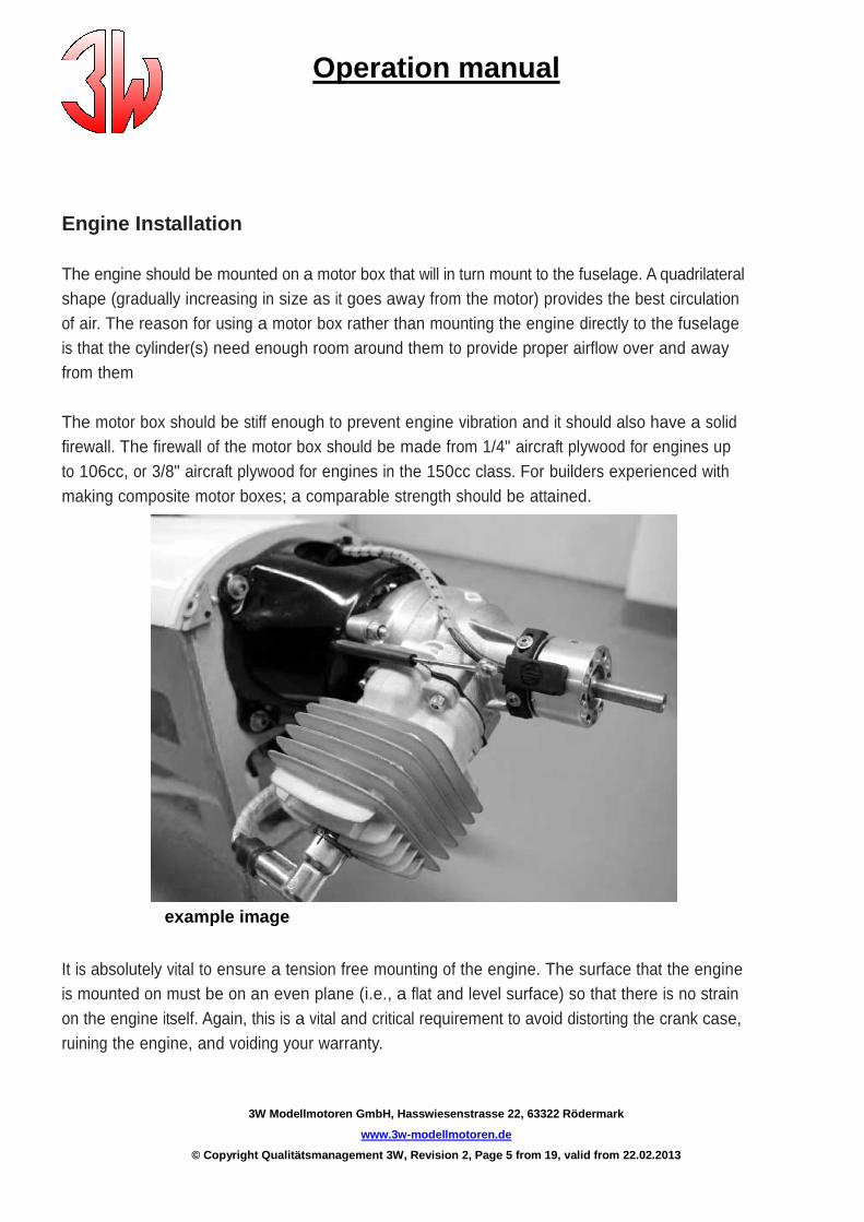
Engine Installation
The engine should be mounted on a motor box that will in turn mount to the fuselage. A quadrilateral shape (gradually increasing in size as it goes away from the motor) provides the best circulation of air. The reason for using a motor box rather than mounting the engine directly to the fuselage is that the cylinder(s) need enough room around them to provide proper airflow over and away from them
The motor box should be stiff enough to prevent engine vibration and it should also have a solid firewall. The firewall of the motor box should be made from 1/4" aircraft plywood for engines up to 106cc, or 3/8" aircraft plywood for engines in the 150cc class. For builders experienced with making composite motor boxes; a comparable strength should be attained. example image
It is absolutely vital to ensure a tension free mounting of the engine. The surface that the engine is mounted on must be on an even plane (i.e., a flat and level surface) so that there is no strain on the engine itself. Again, this is a vital and critical requirement to avoid distorting the crank case, ruining the engine, and voiding your warranty.
Operation manual
3W Modellmotoren GmbH, Hasswiesenstrasse 22, 63322 Rödermark
www.3w-modellmotoren.de
© Copyright Qualitätsmanagement 3W, Revision 2, Pag e 6 from 19, valid from 22.02.2013
Mount the engine to the motor box with high tensile bolts. Once mounted you now have a sub- assembly that you can mount to your fuselage. Spacers can be made from hardwood dowels (3/4" to 1") or machined aluminum bar stock to adjust your down and side thrust. These spacers should go between the motor box and fuselage and not the motor box and engine.
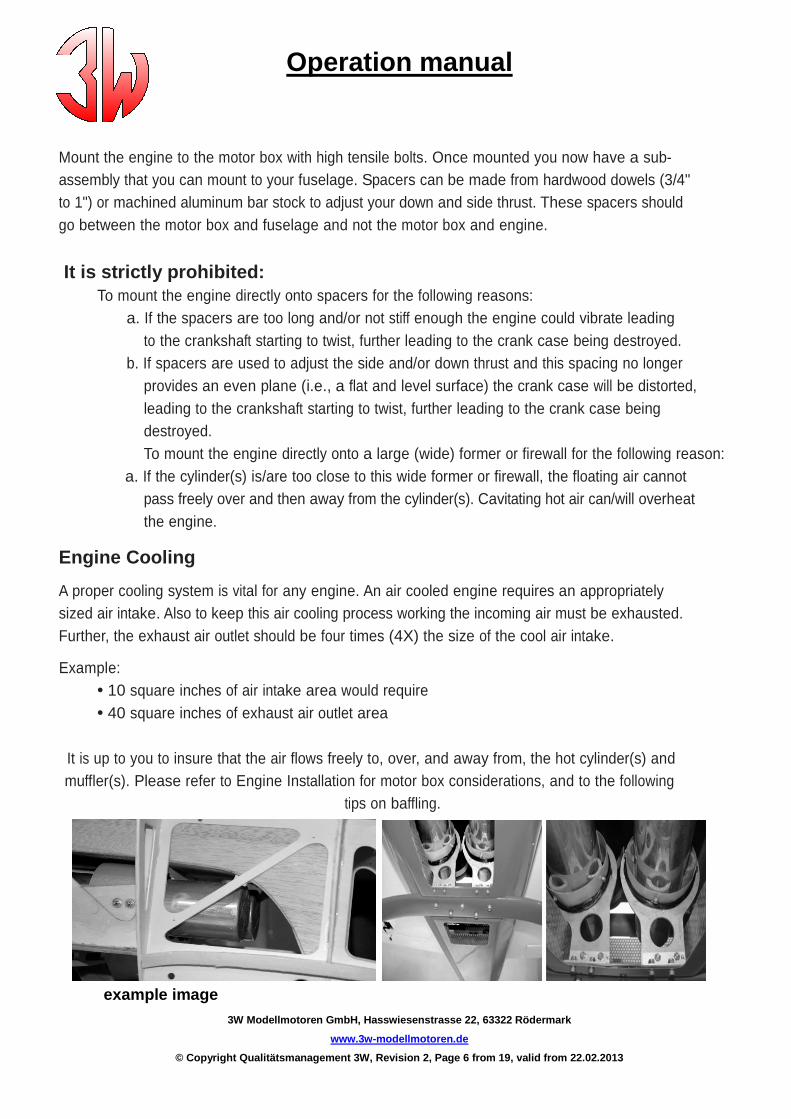
It is strictly prohibited: To mount the engine directly onto spacers for the following reasons: a. If the spacers are too long and/or not stiff enough the engine could vibrate leading to the crankshaft starting to twist, further leading to the crank case being destroyed. b. If spacers are used to adjust the side and/or down thrust and this spacing no longer provides an even plane (i.e., a flat and level surface) the crank case will be distorted, leading to the crankshaft starting to twist, further leading to the crank case being destroyed. To mount the engine directly onto a large (wide) former or firewall for the following reason: a. If the cylinder(s) is/are too close to this wide former or firewall, the floating air cannot pass freely over and then away from the cylinder(s). Cavitating hot air can/will overheat the engine. Engine Cooling A proper cooling system is vital for any engine. An air cooled engine requires an appropriately sized air intake. Also to keep this air cooling process working the incoming air must be exhausted. Further, the exhaust air outlet should be four times (4X) the size of the cool air intake. Example: • 10 square inches of air intake area would require • 40 square inches of exhaust air outlet area
It is up to you to insure that the air flows freely to, over, and away from, the hot cylinder(s) and muffler(s). Please refer to Engine Installation for motor box considerations, and to the following tips on baffling.
example image

Operation manual
3W Modellmotoren GmbH, Hasswiesenstrasse 22, 63322 Rödermark
www.3w-modellmotoren.de
© Copyright Qualitätsmanagement 3W, Revision 2, Pag e 7 from 19, valid from 22.02.2013
Baffling Deflecting of the air (baffling) to and over the cylinder(s) is highly recommended for engine cooling. The idea is to get all of the cool air that is coming through the air intake opening(s) to hit the middle of the cylinder(s) directly, and then be forced over the cylinder(s), creating turbulent air moving through the cylinder(s) fins. The freely flowing, but directed and turbulent air between the fins provides the maximum cooling for an air cooled engine. Without baffling (meaning wood or composite dampers that direct the airflow) the air will take the path of least resistance. Some incoming air will bounce off the cylinder(s) and the rest will escape around the cylinder(s) without coming into contact with the cylinder(s). Engine in pusher operation: Important note! When engines are used operating in pusher configuration cooling gets critical and special attention has to be given to an effective cooling method. A good cooling system layout depends on the actual location (position) of the engine in the fuselage. Operating temperature To be able to check the cylinder head temperature ( CHT ) a thermo element has to be installed which fits under the spark plug ( M 10 thread ). Optimum operating temperature range : 180°C - 220°C. In this range piston, spark plug and combustion chamber will be free of remains. Maximum temperature of 270°C should not be exceeded. During a certain time at full speed the temperature could be 250°C.
Colour of the spark plug should be : light or middle brown. A grey / gray colour is a typical sign for over heating. Temperatures above 270°C are critical and over 300°C, piston can seize and could completely damage the engine.
Temperatures below 180°C create remains ( carbon ) on the piston crown. Increasing remains hit the cylinder and cause abnormal running noises ( knocking ) which will increase the load of the needle bearings and can destroy them. Under extreme conditions the crankshaft can break and a complete damage of the engine will be the result.
Rear induction
Carburetors, whether front or rear, require a steady supply of fresh air. The best way to supply air to a rear carburetor is by installing an air scoop. Some have thought to drill holes into the fuselage near the carburetor area rather than creating an air scoop for the carburetor. This does not work, in fact it will create a vacuum effect that will draw the air away from the carburetor! Again, you should install an air scoop into the front of the plane which will supply air into the fuselage. This air will then need to flow out of the fuselage. Drill exit holes into the rear area of the fuselage for this purpose. Important: The interior of the fuselage must be sealed to prevent damage from gasoline that sprays from the carburetor. Use a thin epoxy or other appropriate fuel proofing method. Do not overlook this step as gasoline will melt some materials like Styrofoam very quickly.
Operation manual
3W Modellmotoren GmbH, Hasswiesenstrasse 22, 63322 Rödermark
www.3w-modellmotoren.de
© Copyright Qualitätsmanagement 3W, Revision 2, Pag e 8 from 19, valid from 22.02.2013
Ignition Consideration needs to be given to the placement of the electronic ignition module. Avoid placing the module in the path of hot air. Important: If the electronic ignition overheats it will malfunction (e.g., backfiring or shutting down).
Ignition details: • The red cable is positive (+) • The ignition timing has been set at our factory • When fitting a new ignition it is important to achieve the correct coordination of the sensor(s) to the magnets
Refer to our special ignition description for furth er information
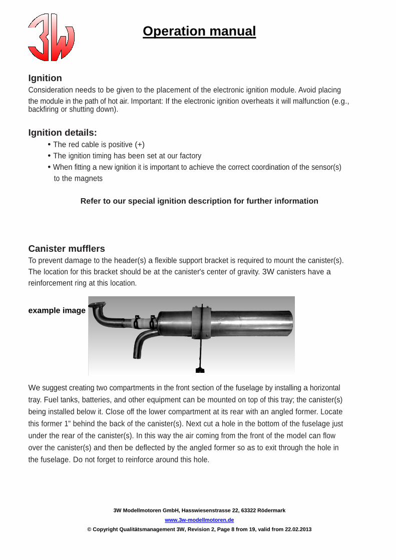
Canister mufflers To prevent damage to the header(s) a flexible support bracket is required to mount the canister(s). The location for this bracket should be at the canister's center of gravity. 3W canisters have a reinforcement ring at this location. example image
We suggest creating two compartments in the front section of the fuselage by installing a horizontal
tray. Fuel tanks, batteries, and other equipment can be mounted on top of this tray; the canister(s)
being installed below it. Close off the lower compartment at its rear with an angled former. Locate
this former 1" behind the back of the canister(s). Next cut a hole in the bottom of the fuselage just
under the rear of the canister(s). In this way the air coming from the front of the model can flow
over the canister(s) and then be deflected by the angled former so as to exit through the hole in
the fuselage. Do not forget to reinforce around this hole.
Operation manual
3W Modellmotoren GmbH, Hasswiesenstrasse 22, 63322 Rödermark
www.3w-modellmotoren.de
© Copyright Qualitätsmanagement 3W, Revision 2, Pag e 9 from 19, valid from 22.02.2013
Important: This exit area needs to be four times (4x) as large as the intake area.
Propellers • Only use propeller brands and sizes that are approved for your engine • The propeller blades must be of the same length • The propeller must be flat (You can check for flatness by putting the propeller on a level surface. The maximum difference of the blade heights should be no more than 1/64".) • The propeller tips must have an identical shape. This is especially important when using 3 or 4 blade propellers. • You must use a drill press to drill your propeller. • You must drill the propeller from the rear. • A drill guide is recommended, but the propeller washer can be used as a drill template. (Fix the propeller washer onto the propeller in the center-bore using a bolt and nut. Drill one hole; put one of the propeller bolts into the hole. Continue until the last bolt is used.) • If you cannot hand tighten all of your prop bolts easily then you have not drilled the propeller correctly. This can lead to sheared propeller bolts. • Balancing your propeller is absolutely critical to the health of your engine. You must keep your propeller balanced. (Propeller balancers are available from DUBRO, and others.) • Always remember that when the engine is running every person must stay behind the line of the rotating propeller; never to the side or the front!
Carburetor settings Before each engine is shipped it has to pass QC and is then test run. We do a basic adjustment of the carburetor needles at that point.
highspeed needle H: 1 low speed needle L: 1 ½
Operation manual
3W Modellmotoren GmbH, Hasswiesenstrasse 22, 63322 Rödermark
www.3w-modellmotoren.de
© Copyright Qualitätsmanagement 3W, Revision 2, Pag e 10 from 19, valid from 22.02.2013
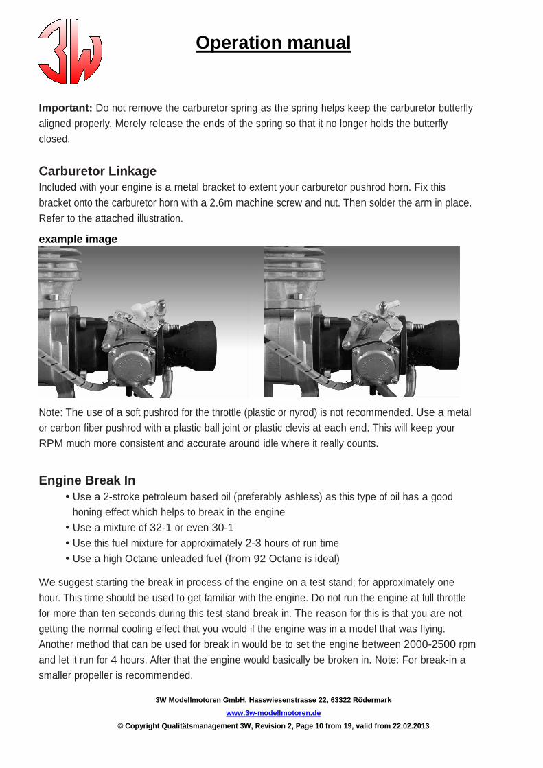
Important: Do not remove the carburetor spring as the spring helps keep the carburetor butterfly aligned properly. Merely release the ends of the spring so that it no longer holds the butterfly closed.
Carburetor Linkage Included with your engine is a metal bracket to extent your carburetor pushrod horn. Fix this bracket onto the carburetor horn with a 2.6m machine screw and nut. Then solder the arm in place. Refer to the attached illustration.
example image Note: The use of a soft pushrod for the throttle (plastic or nyrod) is not recommended. Use a metal or carbon fiber pushrod with a plastic ball joint or plastic clevis at each end. This will keep your RPM much more consistent and accurate around idle where it really counts. Engine Break In • Use a 2-stroke petroleum based oil (preferably ashless) as this type of oil has a good honing effect which helps to break in the engine • Use a mixture of 32-1 or even 30-1 • Use this fuel mixture for approximately 2-3 hours of run time • Use a high Octane unleaded fuel (from 92 Octane is ideal) We suggest starting the break in process of the engine on a test stand; for approximately one hour. This time should be used to get familiar with the engine. Do not run the engine at full throttle for more than ten seconds during this test stand break in. The reason for this is that you are not getting the normal cooling effect that you would if the engine was in a model that was flying. Another method that can be used for break in would be to set the engine between 2000-2500 rpm and let it run for 4 hours. After that the engine would basically be broken in. Note: For break-in a smaller propeller is recommended.
Operation manual
3W Modellmotoren GmbH, Hasswiesenstrasse 22, 63322 Rödermark
www.3w-modellmotoren.de
© Copyright Qualitätsmanagement 3W, Revision 2, Pag e 11 from 19, valid from 22.02.2013
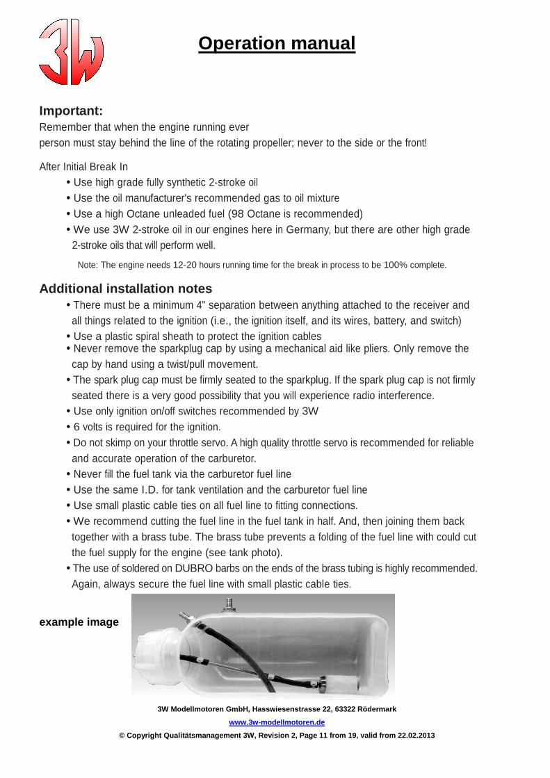
Important: Remember that when the engine running ever person must stay behind the line of the rotating propeller; never to the side or the front! After Initial Break In • Use high grade fully synthetic 2-stroke oil • Use the oil manufacturer's recommended gas to oil mixture • Use a high Octane unleaded fuel (98 Octane is recommended) • We use 3W 2-stroke oil in our engines here in Germany, but there are other high grade 2-stroke oils that will perform well. Note: The engine needs 12-20 hours running time for the break in process to be 100% complete. Additional installation notes • There must be a minimum 4" separation between anything attached to the receiver and all things related to the ignition (i.e., the ignition itself, and its wires, battery, and switch) • Use a plastic spiral sheath to protect the ignition cables • Never remove the sparkplug cap by using a mechanical aid like pliers. Only remove the cap by hand using a twist/pull movement. • The spark plug cap must be firmly seated to the sparkplug. If the spark plug cap is not firmly seated there is a very good possibility that you will experience radio interference. • Use only ignition on/off switches recommended by 3W • 6 volts is required for the ignition. • Do not skimp on your throttle servo. A high quality throttle servo is recommended for reliable and accurate operation of the carburetor. • Never fill the fuel tank via the carburetor fuel line • Use the same I.D. for tank ventilation and the carburetor fuel line • Use small plastic cable ties on all fuel line to fitting connections. • We recommend cutting the fuel line in the fuel tank in half. And, then joining them back together with a brass tube. The brass tube prevents a folding of the fuel line with could cut the fuel supply for the engine (see tank photo). • The use of soldered on DUBRO barbs on the ends of the brass tubing is highly recommended. Again, always secure the fuel line with small plastic cable ties. example image
Operation manual
3W Modellmotoren GmbH, Hasswiesenstrasse 22, 63322 Rödermark
www.3w-modellmotoren.de
© Copyright Qualitätsmanagement 3W, Revision 2, Pag e 12 from 19, valid from 22.02.2013
Warning! Failing to read and follow all of the instructions in this manual can lead to unsafe conditions and damaged equipment. Here are some examples: • Unbalanced propellers can damage the engine's ball bearings, needle bearings, even cause the crankshaft to break • Incorrectly drilled propellers can lead to sheered propeller bolts further leading to accidents and crashes • Loose propeller bolts can also lead to sheered propeller bolts further leading to accidents and crashes. Check these bolts before starting your engine. • Flipping the prop with your hand or fingers can lead to serious accidents! Always use a rubber stick to start the engine! • Not having the plane secure can be lead to serious accidents. Depending on its size use one, two, or more helpers to secure your model. Always tell your helpers to be ready for the model to start at full power. Remember, these engines have a high power output. • Do not put your finger(s), any items, or any other parts of the body into the rotating propeller. • Never tune the carburetor whilst engine is running! Stop the engine. Tune the carburetor and start the engine again. Repeat this procedure until the carburetor is properly tuned. • Make sure that no gasoline will be splashed into the hot muffler(s). • Only 3W mufflers, or mufflers authorized by 3W with an acceptance (test) number, should be used. • Only 3W-ignition systems should be used for proper operation.
Important: Using unauthorized products or failing to follow the instructions in this manual will void your warranty immediately.

Operation manual
3W Modellmotoren GmbH, Hasswiesenstrasse 22, 63322 Rödermark
www.3w-modellmotoren.de
© Copyright Qualitätsmanagement 3W, Revision 2, Pag e 13 from 19, valid from 22.02.2013
Pilots check list We strongly recommend checking the following agenda for your own safety before starting! • Check the propeller bolts for tightness • Check that the spinner is firmly attached • Check the propeller for possible damage • Check to be sure you have the throttle position at idle • Check all batteries • Check servo functions • Check to see that the ignition switch is OFF • Check pressure (6-8 bar) system of retract (if applicable) • Check all linkages for play • Check your wheels for possible damage and easy running • Check the wing mounting for tight fit and proper attachment • Check the canopy for tight fit and proper attachment • When starting the engine one person (minimum) has to hold the model
Operation manual
3W Modellmotoren GmbH, Hasswiesenstrasse 22, 63322 Rödermark
www.3w-modellmotoren.de
© Copyright Qualitätsmanagement 3W, Revision 2, Pag e 14 from 19, valid from 22.02.2013
Starting Procedure
If you have read and understood this entire manual, and followed its recommendations, you are ready to start your new engine. • Use a rubber stick to start the engine. Never use your hand or fingers! • Insure that your receiver batteries are charged and your receiver is on • Insure that your ignition battery(s) are charged • Insure that your transmitter is on, and that your throttle is set to low • Insure that your plane is properly and safely anchored (use one, two, or more people if necessary) • Close the choke(s) • Switch on the ignition • Flip the propeller until the engine "pops" (starts and stops quickly) • Wait for the propeller to stop spinning, turn off the ignition, and open the choke(s) • Switch the ignition back on • Flip the propeller again until the engine starts • Warm-up the engine for at least 20 seconds • Due to the high power and torque of the engine(s) it is not recommended to open the throttle abruptly
Precision tuning of the carburetor
The use of a tachometer is highly recommended. And, again, never adjust the needles while the engine is running! 1. Using the tachometer tune the engine for maximum power with the high needle (H). 2. Again using the tachometer; richen the high needle (H) until the motor runs 100-200 RPM less than the maximum RPM. Now you are tuned slightly rich on the high needle (H). 3. Let the engine run at idle for one minute. Check to see that the idle RPM remains constant. 4. If the idle RPM drops until the engine stops; the low needle (L) is too rich. Lean the low needle (L) until a constant idle RPM is achieved. 5. Check the transition with a quick throttle advance. The engine should not sound strained at any time. It should sound like it is making quick steady power; without any hesitation. 6. An optimally tuned engine will feel a bit rich after a cold start. It will start to run right after it has warmed up for approximately one minute.
Operation manual
3W Modellmotoren GmbH, Hasswiesenstrasse 22, 63322 Rödermark
www.3w-modellmotoren.de
© Copyright Qualitätsmanagement 3W, Revision 2, Pag e 15 from 19, valid from 22.02.2013
Trouble Shooting
Problem The engine is flooded (the crankshaft housing is filled with fuel). Solution Remove the spark plug; turn the engine to a position where the fuel runs out.
The engine starts after being choked but then stops soon after. The low needle on the carburetor is probably too lean. Go back to the recommended settings and adjust your carburetor from there. This problem may also indicate a dirty carburetor or faulty ignition.
The engine runs rough and is vibrating strongly. Balance the propeller. Check the ignition timing. Check your plumbing for air/fuel leaks. Check your spark plug for carbon and check the spark plug gap. Check the motor mount to be sure it is rigid. Check to make sure the engine is mounted on a level surface so that the crankcase is free of tension. Check the engine and propeller bolts.
The engine doesn't reach a normal RPM at full throttle. Check the carburetor settings. Check to see if the propeller is too large. Verify that you have the correct muffler system. Check to see if the engine is overheating. Check the ignition timing. Check the spark plug for defect. Verify you have the correct gasoline, oil, and have mixed them with the correct ratio.

Operation manual
3W Modellmotoren GmbH, Hasswiesenstrasse 22, 63322 Rödermark
www.3w-modellmotoren.de
© Copyright Qualitätsmanagement 3W, Revision 2, Pag e 16 from 19, valid from 22.02.2013
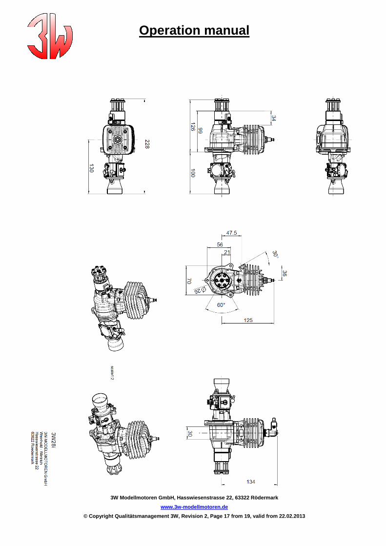
Metrics Techn. specifications
28i 28i CS
Cylinder capacity 1.74 cu.in 1.74 cu.in
Power 3.35 HP / 2,5 kW 3.55 HP / 2.65 kW
Bore dia. 1.42 in 1.42 in
Stroke 1.10 in 1.10 in
Speed range 1500 - 8500 min-1 / rpm
Weight 2.67 Ibs incl. ignition
Crankshaft 3 ball bearings
Connection rod Needle bearings on both ends
Gasoline-Version 1 : 50 – 2% Mix, full syntethic oil, high Octane unleaded fuel (from 92 Octane is recommended)
IIS – Ignition 6,0 – 8,4V
Propeller 2-Bladed: 16 x 10; 18 x 8; 18 x 10; 16 x 10; 18 x 8; 18 x 10; 20 x 8 20 x 8 Propeller 3-Bladed: 16 x 8; 16 x 10 16 x 8; 16 x 10
Operation manual
3W Modellmotoren GmbH, Hasswiesenstrasse 22, 63322 Rödermark
www.3w-modellmotoren.de
© Copyright Qualitätsmanagement 3W, Revision 2, Pag e 17 from 19, valid from 22.02.2013
Operation manual
3W Modellmotoren GmbH, Hasswiesenstrasse 22, 63322 Rödermark
www.3w-modellmotoren.de
© Copyright Qualitätsmanagement 3W, Revision 2, Pag e 18 from 19, valid from 22.02.2013
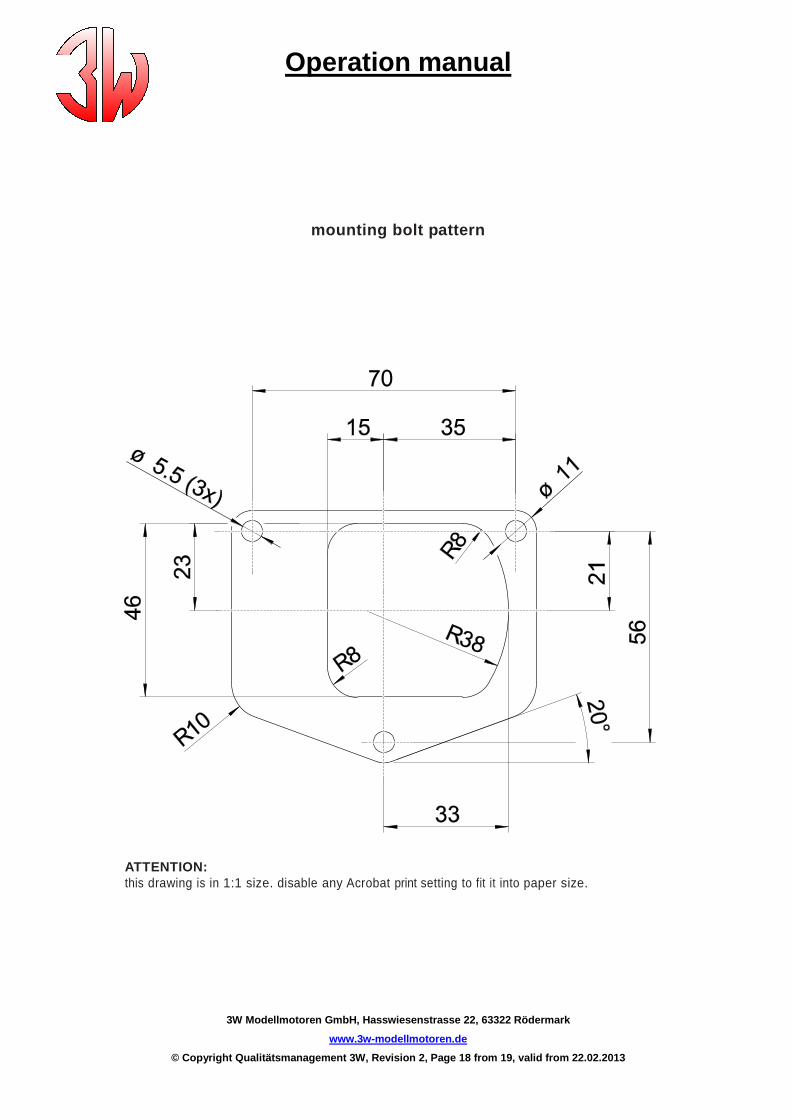
mounting bolt pattern
ATTENTION: this drawing is in 1:1 size. disable any Acrobat print setting to fit it into paper size.

Operation manual
3W Modellmotoren GmbH, Hasswiesenstrasse 22, 63322 Rödermark
www.3w-modellmotoren.de
© Copyright Qualitätsmanagement 3W, Revision 2, Pag e 19 from 19, valid from 22.02.2013
Guarantee conditions
We grant a 36 month guarantee as from purchase date or 1200 operating hours. This guarantee applies solely to the free replacement of defective parts resulting from faulty material or manufacturing. We point out that guarantee is effective only if joined to the apparatus to be repaired. Na claim conceming a defect caused by noncompliance with operation instructions, mishandling, unsuitable spare parts and unskilled repairs will be acknowledged. Please ask your dealer to fill in this guarantee at time of purchase. Keep this certificate carefully because your claim is valid only upon presentation of this document. This guarantee is valid only when accompanied with the official shop receipt. Warranty terminates if unauthorised modifications are done.
Garantie-Bedingungen
Wir geben auf unsere Geräte 36 Monate, oder 1200 Betriebsstunden, Vollgarantie ab Verkaufsdatum. Die Garantie ist ausschließlich beschränkt auf den kostenlosen Ersatz defekter Teile, deren Mängelursache Konstruktions- oder Materialfehler sind. Wir möchten ausdrücklich darauf hinweisen, dass die Garantie nur dann erfüllt wird, wenn der Garantieanspruch gleichzeitig mit dem Reparaturauftrag geltend gemacht wird. Beachten Sie auch bitte, dass wir einen Garantieanspruch nicht akzeptieren können, wenn die Störung durch unsachgemäße Behandlung (siehe Gebrauchsanweisung), durch natürliche Abnutzung, durch Verwendung fremder Ersatzteile oder Reparaturen durch andere entstehen. Lassen Sie auf dieser Garantiekarte das Kaufdatum durch den Händler eintragen, oder heften Sie die Kaufquittung dazu. Bewahren Sie diese Garantiekarte sorgfältig auf, denn ein Garantieanspruch ist leider hinfällig, wenn sie bei einer Reklamation nicht vorgelegt werden kann. Diese Garantie ist nur gültig, wenn sie zusammen mit einem Kaufsbeleg vorgewiesen wird (Ladenquittung). Bei nicht autorisierten Änderungen Erlischt die Garantie.