Embed Size (px)
Citation preview

EUROPEAN ORGANIZATION FOR NUCLEAR RESEARCH
CERN SL/95{90 (AP)
DYNAMIC APERTURE ESTIMATES
AND PHASE SPACE DISTORTIONS
IN NONLINEAR BETATRONIC
MOTION
E. Todesco� and M. Giovannozzi
Abstract
Symplectic mappings which modelize the 4D betatronic motion ina magnetic lattice are considered. We de�ne the dynamic aperturein terms of the connected volume in phase space of initial conditionswhich are bounded for a given number of iterations. Di�erent meth-ods for a fast estimate of this quantity are given; the analysis of theassociated errors and the optimization of the integration steps areoutlined. A comparison of the accuracy of these methods is given forboth simple models and more realistic lattices.
Submitted to Phys. Rev. E
Geneva, Switzerland
November 29, 1995
� INFN, Sezione di Bologna, Via Irnerio 46, I-40126 Bologna.Work partially supported by EC Human Capital and Mobility contractNr. ERBCHRXCT940480

1 INTRODUCTION
The presence of nonlinearities in the magnetic �eld of the elements of an acceler-ator can greatly reduce the stability domain, i.e., the region in phase space whereone can safely operate with the beam [1], [2], [3]. An accurate estimate of thedimension of this domain, which is related to the so{called dynamic aperture, iscrucial both for the understanding of the dynamics of existing machines [3] andfor the speci�cation of the lattice parameters of planned machines [4].
In this paper we restrict ourselves to the analysis of the nonlinear oscillationsof the beam in the plane (x; y) transverse to the orbit (betatronic motion). Fixinga section of the machine, we analyse the dynamics in the four{dimensional phasespace (x; px; y; py), px and py being the momenta associated to x and y.
The numerical estimate of the dynamic aperture is related to the computationof the volume in phase space of the initial conditions that are stable after a givennumber of revolutions around the machine. This set can be rather irregular,and it can have holes: in fact, initial conditions arbitrarily close to the origincan be unstable. This phenomenon, universally known as Arnold di�usion [5],occurs in systems whose phase space has dimension higher than two. Even if it isgeneral belief that this e�ect is not of practical relevance for accelerator physics,it appears that it is di�cult to give a rigorous de�nition of the dynamic aperture.
Moreover, the main di�culty in determining a reliable estimate of the stabilitydomain for complicated lattices does not only stem from theoretical arguments.In fact, a numerical evaluation of the volume of the stable initial conditions isvery CPU time consuming, as in principle one should scan the four variables(x; px; y; py).
To overcome these problems for complicated lattices, a pragmatic approachhas been proposed [2] [3]: tracking is carried out over initial conditions with zerophases (px = py = 0) and a �xed ratio x=y (in most cases one uses x=y = 1), witha large gain in the CPU time. Unfortunately, this approach is not completelycorrect as it does not take into account two main e�ects, namely the distortion ofthe orbits along the phases and the di�erent dynamics of the particles with variousratios x=y. The in uence of the distortion along the phases can be evaluatedthrough the smear. This quantity measures the standard deviation of the particleamplitude along the orbit [6]. Moreover, several studies have been performed toanalyse the dynamics of particles with various ratios of x=y (see for instance [1][3] [7]). Neglecting these e�ects, the computed dynamic aperture will be a�ectedby errors which cannot be estimated a priori.
To �nd an e�cient and correct way to estimate the dynamic aperture is thekey point in problems like that of sorting the magnets according to their randommagnetic errors [8]. In fact, as for all the optimization procedures, the analysisof the errors a�ecting the computation of the dynamic aperture is crucial todetermine the validity of the correcting schemes. Furthermore, the study of therandom errors requires to consider a rather large number of realizations of these
2

errors: the knowledge of the dependence of the accuracy on the integration stepsallows one to choose the best compromise between CPU time and accuracy.
In this paper we present some original numerical methods to evaluate thedynamic aperture taking into account the phase space distortions. The �rst stepin this analysis is to give a de�nition of dynamic aperture. We de�ne it as theaverage distance in phase space of the border of stability, i.e. as the radius ofthe hypersphere whose volume is equal to the connected volume of stable initialconditions for a �xed number of iterations. Then we develop some algorithms forits evaluation. The direct implementation of the complete integration in phasespace is very CPU time consuming: we show that in order to obtain a relativeerror of 1=(4J), one has to evaluate J4 orbits using an optimized integration.
Indeed, we show that it is possible to exploit the dynamics to take into accountthe distortion of the orbits along the phases, thus avoiding the integration overthese variables. As a result, the simulations are considerably faster, and oneobtains an optimized relative error of the order of 1=(4J) by evaluating onlyJ2 orbits. We develop two algorithms to carry out these fast estimates: the
�rst one is based on numerical integration [9], whilst the second one exploits theperturbative tools of normal forms [10] [11] [12].
We have carried out numerical simulations in order to check the e�ectivenessof our techniques, and to show that phase space distortions can be rather relevant.We analysed the H�enon map [12] [13], a LHC{like cell lattice with random errors[8], and a SPS lattice used for experiments [14]. All the computations were carriedout for a short{term tracking (1000 turns). The results show that for the H�enonmap and for the LHC{like cell lattice our estimates of the dynamic aperture arerather accurate (2%{3%). On the other hand, the results obtained by trackingparticles with zero phases and satisfying x=y = 1 are by far less accurate (5%{15%). This is an indication of the fact that the phase space distortions are notnegligible. In the case of the SPS lattice the situation is even worse due to thestrong non linearities: the fast estimate along the line x=y = 1 is a�ected by avery strong error (15%{45%), whilst our methods are still reliable, even thoughthe strong nonlinearities in the model reduce the accuracy with respect to theprevious cases (6%{9%). The e�ect of long-term and of neglected ingredients(for instance, modulation due to ripple) can reduce the very strong phase spacedistortions found for the SPS model: we present the short term results in order totest the precision of the outlined methods in the situations where the distortionis higher.
The structure of the paper is the following: in section 2 we consider the 2Dbetatronic motion, which is propaedeutic to the analysis of the more realistic4D case. In 2.1 we introduce the notations; in 2.2 we give a de�nition of dy-namic aperture and in 2.3 the algorithms are presented. A detailed discussionof the error sources and of the implementation can be found in the Appendix A.In section 2.4 the numerical results are presented. The same structure is usedfor section 3, where the 4D case is analysed. Concluding remarks are given in
3

section 4.
2 2D betatronic motion
2.1 The model
We consider the transverse motion in a circular particle accelerator: let F be theone{turn map [10] [11] [12] which gives the position xn+1 of a single particle inphase space as a function of its position at the previous turn xn:
xn+1 = F(xn): (1)
The iterates of the one{turn map are computed through the successive applicationof the maps of each element (tracking procedure). In this section we restrictourselves to the analysis of the 2D betatronic motion, i.e. we have x = (x; px).We assume that x; px are the Courant{Snyder coordinates, so that the linearpart of the map is a rotation by a constant angle ! = 2��. The parameter �is the linear tune. The phase space of the map has a well known structure [5][12]: around the origin, which is an elliptic �xed point, one has closed curves (1DKAM tori), and wherever the nonlinear tune satis�es a resonant condition, theinvariant curves are broken into islands; when nonlinearities are dominant, onereaches a stability border beyond which a fast escape to in�nity occurs.
The KAM tori separate di�erent phase space domains, i.e. an initial conditioninside a KAM torus cannot cross it: therefore, there exists a last connectedinvariant curve whose interior represents a set of stable initial conditions. Outsidethis curve, one can only have islands of stability, scattered in the sea of initialconditions which escape to in�nity. In Fig. 1 we plot the phase portrait of theH�enon map [see Eq. (6), where the parameter � is set to zero] whose linearfrequency is � = 0:28. The last connected invariant curve is marked in boldface;one can also observe a chain of islands of period 15 outside the stable domain.
2.2 Dynamic aperture de�nition (2D case)
The stability domain of the one{turn map of Eq. (1) is given by the area of theset of initial conditions enclosed by the last connected stable invariant curve. Wede�ne the dynamic aperture as the radius of the circle whose area is equal to thearea of the stability domain. We make the following remarks:
� Islands: The above de�nition excludes the islands of stability which areusually neglected in accelerator physics, since they are not a safe place whereto inject the beam.
� Why phase space ? One has to consider the area in phase space x = (x; px)and not only the projection of this area on the physical space x. In fact,even though one is interested in the physical dimension of the allowed stable
4

domain for the beam, the betatronic motion exchanges the roles of x and pxalong the circumference of the machine.
� Long-term stability. The above de�nition is valid for in�nite times; in fact, inaccelerator physics, one is interested in stability over long but �nite times,corresponding to the typical time of the experiment run. For a machinesuch as the planned LHC [4] this time is of the order of 108 turns, which isbeyond the capability of modern computers: therefore, one usually considersshort term stability (i.e. � 1000 turns) as a �rst indication. More re�nedestimates can be obtained through medium{term tracking in conjunctionwith numerical tools such as Lyapunov exponents [15] or survival plots [16].In the followings, we will always consider the dynamic aperture as a functionof the number of iterates, without dealing with the relation between short-term and long-term stability.
2.3 Methods to compute the 2D dynamic aperture
� Method 1: direct integration. Let us de�ne �(x; px) as the characteristicfunction of the set of initial conditions which are bounded under N iter-ations [i.e. �(x; px) is zero if the orbit with initial condition (x; px) is lost,and unity if it is stable after N iterations]. Then, the dynamic aperture isrelated to the area of this set in phase space:
Z Z�(x; px) dx dpx: (2)
Since the linear motion is a rotation by a constant angle, it is natural to usepolar coordinates (r; #):
Z 2�
0
Z1
0�(r cos#; r sin#) r dr d#: (3)
Having �xed #, let r(#) be the distance along # of the last connected invari-ant curve (i.e., the curve marked in boldface in Fig. 1). Then, we de�ne thearea of the stability domain as
A# =Z 2�
0
Z r(#)
0r dr d# =
1
2
Z 2�
0r(#)2d#: (4)
In this way, one neglects the contribution given by the stable islands outsidethe last connected invariant curve. The subscript indicates that an averageover the angle # is carried out. The details of the implementation of thisapproach are given in Appendix A.1.
Indeed, once the last stable invariant curve is found for a given direction#, one already knows the whole orbit through numerical iteration. Thisimplies that the scan in the initial conditions over the angle can be avoided
5

if one can evaluate the area of the orbit (i.e. the nonlinear invariant), giventhe N iterates. We will describe two di�erent approaches which provide anestimate of the invariant of motion. Hence one can avoid to scan the angle# with a substantial reduction of the CPU time.
� Method 2: integration over the dynamics. In this case, we �x an angle #,and we de�ne r(#) as in Method 1. We evaluate N iterates of the orbitwith initial condition (r(#) cos #; r(#) sin#); let r(n)(#) and #
(n)(#) be theamplitudes and the phases of the n{th iterate. In order to estimate the areaof the last stable curve, one can replace the average of r2 over the angle [seeEq. (4)] with the average over the iterates (namely we are replacing a spaceaverage with a time average):
1
2�
Z 2�
0r2(#) d# �! lim
N!1
1
N
NXn=1
[r(n)(#)]2: (5)
The dependence of the r.h.s. on the choice of # is very weak, since every# should approximate the same orbit provided the integration step in r issmall enough. Nevertheless, in order to carry out the substitution (5), onehas to assume the following hypotheses.
{ The frequency of the last invariant curve is irrational, i.e. the iteratesare dense on the last invariant orbit.
{ The invariant measure associated to the dynamics over the last stablecurve is uniform, i.e. the distribution of the phases of the iterates onthe last invariant curve is constant.
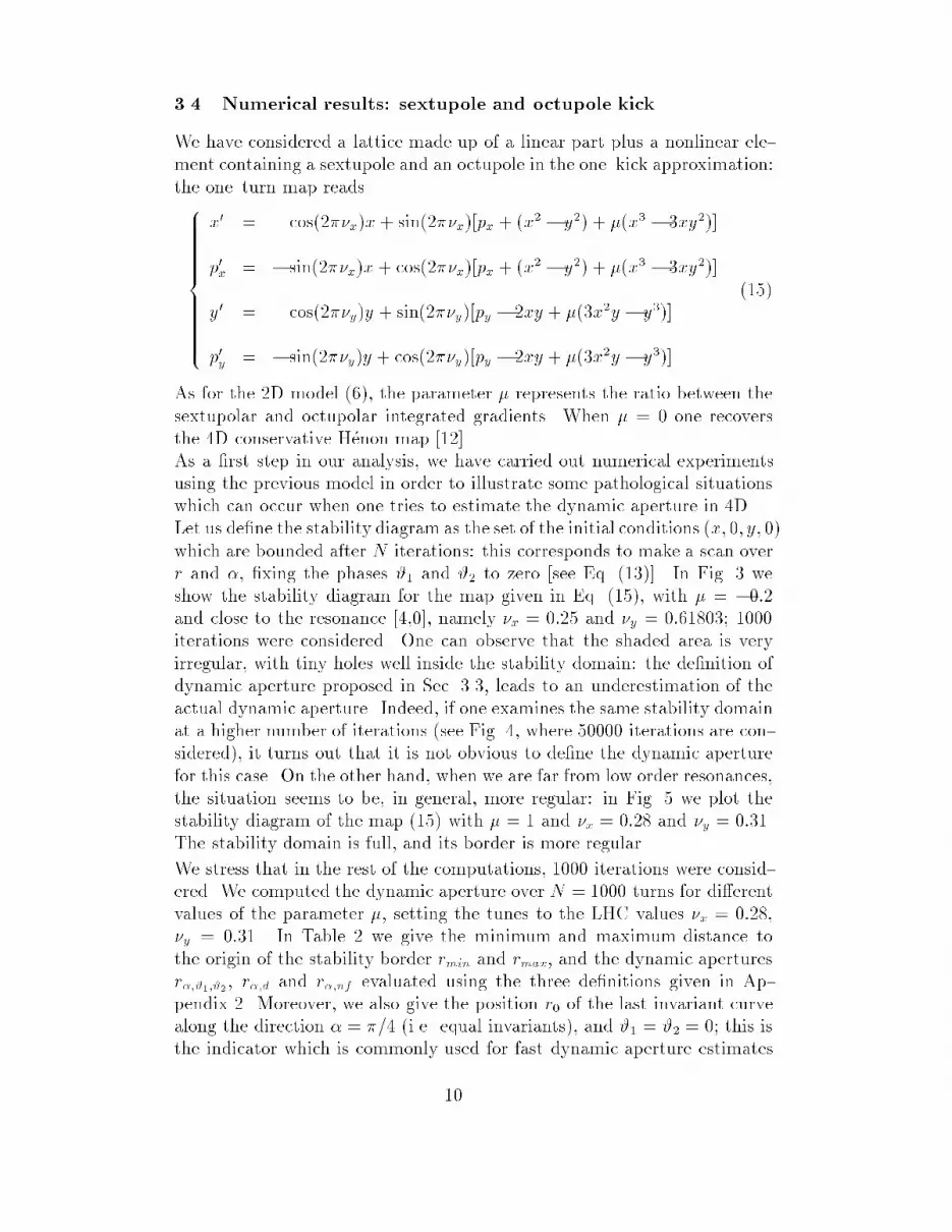
In Fig. 2 we plot the distribution of the phases of 50000 iterates of the laststable curve of the H�enon map at � = 0:28. One can see that, even if theiterates are dense on the angular interval [0; 2�] (i.e., there are no gaps),the distribution is far from being uniform. This e�ect is well known [5] [12]:close to hyperbolic (i.e. unstable) �xed points, which arise from nonlinearresonances, the motion can be very slow, and therefore the distributionof the iterates over the invariant curve can be signi�cantly non uniform.In fact, the four major peaks in Fig. 2 correspond to the four hyperbolic�xed points which lie outside the stability domain (see Fig. 1). In orderto cure this e�ect one has to carefully consider the information folded inthe dynamics [9]. In Appendix A.2 we give the details of this method; theobtained dynamic aperture estimate is denoted by rd.
� Method 3: normal forms. The normal forms series allow one to give an an-alytic approximation of the orbit in phase space, and therefore provide an-other method to estimate the dynamic aperture. According to the nonreso-nant normal form theory, one conjugates the map F with a normal form U,which is an amplitude{dependent rotation, using a conjugating function �(see Ref. [10] [11] and [12]). The orbits of F are transformed through the
6

inverse conjugating function = ��1 to circles in the normalized plane.Since is area{preserving, the area of the last stable orbit (i.e. the dynamicaperture) can be evaluated by taking � times the radius of the orbit trans-formed in the normalized space. In Appendix A.3 we give the details of theimplementation of this algorithm; the obtained dynamic aperture estimateis denoted by rnf .
2.4 Numerical results
We consider a lattice model made up of a linear part plus a nonlinear elementcontaining a sextupole and an octupole in the one{kick approximation:
8><>:
x0 = cos(2��x)x+ sin(2��x)(px + x
2 + �x3)
p0
x = � sin(2��x)x+ cos(2��x)(px + x2 + �x
3);(6)
where � can be expressed as
� =1
3
K3
K2
q�: (7)
The quantitiesK2;K3 represent the integrated sextupolar and octupolar gradientrespectively, whilst � is the value of the beta function in the nonlinear element.
When � = 0 one obtains the conservative H�enon map [12]. We computed thedynamic aperture over N = 1000 turns for di�erent values of the parameter �,having set the tune to the value �x = 0:28. In Table 1 we show the dynamicapertures evaluated using the described methods (i.e., r#, rd and rnf ); moreoverwe give the minimum rmin and the maximum rmax distance of the last invariantcurve from the origin, and its intersection r0 with the positive x axes. We usedr# computed with 100 steps for each variable as the exact dynamic aperture:indeed, this estimate is a�ected by a relative error of the order of 1%; we veri�edthe validity of the error bound by varying the number of integration steps andchecking the stability of the computed dynamic aperture within the error. In thelast row of Table 1 the average relative error of r0, rd, rnf with respect to r� isgiven.
In all the numerical simulations, the number of steps in r was 100; rd wascomputed over 100 iterates, and the normal form estimate rnf was evaluatedusing a truncation order between 3 and 8, choosing the order which minimizesthe error provided by the composition of the conjugating functions � and .
In all the cases considered, there is a wide distortion of the phase space, andtherefore r0 is a bad estimate of the stability area in phase space. Nevertheless,both rd and rnf can provide rather accurate estimates of the dynamic aperturewithout making the scan over the angle.
7

3 4D betatronic motion
3.1 The model
We analyze a 4D symplectic mapping, which can be written as
x0 = F(x) x = (x; px; y; py) (8)
where x is now a vector in the 4D euclidean phase space. The linear motion isgiven by the direct product of two constant rotations in the planes (x; px) and(y; py) by the linear tunes �1 and �2.
3.2 Dynamic aperture de�nition (4D case)
Let us consider the phase space volume of the initial conditions which are boundedafter N iterations: Z Z Z Z
�(x; px; y; py) dx dpx dy dpy; (9)
where �(x; px; y; py) is the generalization of the characteristic function [see Eq. (2)]to the 4D case. Since in 4D the invariant curves (i.e. 2D KAM tori) do not sepa-rate di�erent domains of phase space, the concept of last invariant curve (whichsurrounds stable initial conditions) is not valid anymore [5] [12]. In principle,the stability domain for a �xed number of iterations could be a rather peculiarset in phase space, with holes and very irregular structures. However, it seemsfrom numerical simulations [2] [3] [7] [8] [16] that these situations are not typicalof weakly nonlinear lattices, where these structures have no practical relevance,since they occupy a negligible fraction of the phase space volume. Therefore, ingeneral, there exists a connected region of initial conditions which are stable fora given number of iterations.
3.3 Methods to compute the 4D dynamic aperture
In this section we will generalize the methods already presented for the two{dimensional case (again the details can be found in the Appendix 2).
� Method 1: direct integration. In order to exclude the disconnected part ofthe stability domain in the integral (9), we have to choose a suitable co-ordinate transformation. Since the linear motion is the direct product ofconstant rotations, the natural choice is to use polar variables (r1; #1; r2; #2):r1 and r2 are the linear invariants. The nonlinear part of the equations ofmotion adds a coupling between the two planes, the perturbative parameterbeing the distance to the origin. Therefore it is natural to replace r1 and r2
8

with the polar variables r cos� and r sin�:8>>>>>>>>>>><>>>>>>>>>>>:
x = r cos� cos #1
px = r cos� sin#1 r 2 [0;+1[#1; #2 2 [0; 2�[
y = r sin� cos #2 � 2 [0; �=2]
py = r sin� sin#2;
(10)
substituting in Eq. (9) we obtainZ 2�
0
Z 2�
0
Z �=2
0
Z1
0�(r; �; #1; #2) r
3 sin(�) cos(�) dr d� d#1 d#2: (11)
Having �xed �, #1 and #2, let r(�; #1; #2) be the �rst value of r whose orbitis not bounded after N iterations. Then, the area of a connected stabilitydomain is
A�;#1;#2 =1
8
Z 2�
0
Z 2�
0
Z �=2
0[r(�; #1; #2)]
4 sin(2�) d� d#1 d#2: (12)
In this way one excludes stable islands which are not connected to the mainstable domain. In principle, this method can lead to also exclude connectedparts. We de�ne the dynamic aperture as the radius of the hypersphere thathas the same volume as the stability domain:
r�;#1;#2 =�2A�;#1;#2
�2
�1=4: (13)
� Method 2: integration over the dynamics. The generalization of Method 2to the 4D case is straightforward and it will be discussed in Appendix 2.2;the obtained dynamic aperture estimate is denoted by r�;d.
� Method 3: normal forms. According to the nonresonant normal form theory,using a conjugating function � one transforms a 4D map F into its normalform U [11] [12] [8]. The normal form is a direct product of rotations in thetwo phase planes (x; px) and (y; py), whose nonlinear frequencies depend onthe distance to the origin. The two components of the inverse conjugatingfunction 1 and 2 give the approximated nonlinear invariants �1 and �2.Again r(�; #1; #2) stands for the �rst value of the radial coordinate for whicha particle loss occurs along the direction �; #1; #2, then, thanks to the prop-erties of the normal forms, the nonlinear invariants �1; �2 will be independenton the values of the phases #1; #2. Therefore in Eq. 12 the integration overthe phases can be trivially computed, and the �nal result will be
A�;nf =�2
2
Z �=2
0[�1(r; �) + �2(r; �)]
2 sin(2�) d� (14)
The details of the implementation of this approach are given in Appendix 2.3;the obtained dynamic aperture estimate is denote by r�;nf .
9
3.4 Numerical results: sextupole and octupole kick
We have considered a lattice made up of a linear part plus a nonlinear ele-ment containing a sextupole and an octupole in the one{kick approximation:the one{turn map reads8>>>>>>>>>>><>>>>>>>>>>>:
x0 = cos(2��x)x+ sin(2��x)[px + (x2 � y
2) + �(x3 � 3xy2)]
p0
x = � sin(2��x)x+ cos(2��x)[px + (x2 � y2) + �(x3 � 3xy2)]
y0 = cos(2��y)y + sin(2��y)[py � 2xy + �(3x2y � y
3)]
p0
y = � sin(2��y)y + cos(2��y)[py � 2xy + �(3x2y � y3)]
(15)
As for the 2D model (6), the parameter � represents the ratio between thesextupolar and octupolar integrated gradients. When � = 0 one recoversthe 4D conservative H�enon map [12].As a �rst step in our analysis, we have carried out numerical experimentsusing the previous model in order to illustrate some pathological situationswhich can occur when one tries to estimate the dynamic aperture in 4D.Let us de�ne the stability diagram as the set of the initial conditions (x; 0; y; 0)which are bounded after N iterations: this corresponds to make a scan overr and �, �xing the phases #1 and #2 to zero [see Eq. (13)]. In Fig. 3 weshow the stability diagram for the map given in Eq. (15), with � = �0:2and close to the resonance [4,0], namely �x = 0:25 and �y = 0:61803; 1000iterations were considered. One can observe that the shaded area is veryirregular, with tiny holes well inside the stability domain: the de�nition ofdynamic aperture proposed in Sec. 3.3, leads to an underestimation of theactual dynamic aperture. Indeed, if one examines the same stability domainat a higher number of iterations (see Fig. 4, where 50000 iterations are con-sidered), it turns out that it is not obvious to de�ne the dynamic aperturefor this case. On the other hand, when we are far from low order resonances,the situation seems to be, in general, more regular: in Fig. 5 we plot thestability diagram of the map (15) with � = 1 and �x = 0:28 and �y = 0:31.The stability domain is full, and its border is more regular.
We stress that in the rest of the computations, 1000 iterations were consid-ered. We computed the dynamic aperture over N = 1000 turns for di�erentvalues of the parameter �, setting the tunes to the LHC values �x = 0:28,�y = 0:31. In Table 2 we give the minimum and maximum distance tothe origin of the stability border rmin and rmax, and the dynamic aperturesr�;#1;#2, r�;d and r�;nf evaluated using the three de�nitions given in Ap-pendix 2. Moreover, we also give the position r0 of the last invariant curvealong the direction � = �=4 (i.e. equal invariants), and #1 = #2 = 0; this isthe indicator which is commonly used for fast dynamic aperture estimates
10

of complicated lattices [2] [3]. In the last row we quote the average rela-tive errors with respect to r�;#1;#2 computed with 20 steps for each variable:this dynamic aperture estimate is a�ected by a relative error of the order of2%; also in this case, we veri�ed the validity of the error bound by varyingthe number of integration steps and checking the stability of the computeddynamic aperture within the error. For the methods which avoid the in-tegration over the phases, the number of steps in � and in r is 20; r�;d iscomputed over 1000 iterates. The normal form truncation is carried withthe same criteria used for the 2D case.
Both the normal form and the average over the dynamics give very good es-timates. Although the evaluation of the dynamic aperture along the bisetrixr0 is more precise than in the 2D case, it is a�ected by an average error of6%.
3.5 Numerical results: LHC cell lattice with random errors
We consider a lattice made up of 8 LHC{like cells [4] plus a phase shifter toset the linear tunes to the values �x = 0:28, �y = 0:31. Two di�erent sets ofnonlinearities have been considered:
{ A lattice with only random sextupolar components in the dipoles.
{ A lattice with random sextupolar, octupolar and decapolar componentsin the dipoles.
The multipolar gradients have been set to the estimated values of the LHCdipole errors. For each case we analysed 10 di�erent seeds. In Table 3 wereport the relative errors between Methods 2, 3, and Method 1. The samevalues of the number of steps as in the previous 4D model have been used.The results con�rm the trend of the data shown in Table 2: both r�;d andr�;nf provide an estimate of the dynamic aperture which is in agreementwith the direct integration of the stability domain, without making the scanover two angles #1 and #2. The fast dynamic aperture estimate r0 (carriedalong one direction in phase space) neglects both the distortion of the orbitand the contributions coming from particles with di�erent emittances: thesephenomena are relevant, and thus make this estimate rather imprecise.
3.6 Numerical results: SPS
Finally, we consider the SPS lattice corresponding to the set{up used fornonlinear dynamics experiments [14]. The nonlinear part of the lattice ismade up by 8 strong extraction sextupoles, and by 108 chromatic sextupoles.Two working points have been considered: the �rst one (WP1) at �x =26:637 and �y = 26:533, which is close to resonances of order 7 and 8;the second one (WP2) is �y = 26:605 and �y = 26:538, which is close to
11

resonances of order 5. Both working points correspond to very perturbedsituations where the nonlinear resonances are excited and the phase spaceis strongly deformed. In Fig. 6 we plot the stability diagrams previouslyde�ned in section 3.4 of WP1 and WP2 respectively. The dependence ofthe stability domain on the ratio of the invariants is extremely irregular. InTable 3 the di�erent estimates of the dynamic aperture r0, r�;d and r�;nf arecompared to the estimate r�;#1;#2 computed with 20 steps in each variable.The results show that, due to the high distortion in phase space, the estimater0, obtained on the line x=y = 1 is really imprecise (15%{40%). On the otherhand, Methods 2 and 3 provide a better estimate, even if the error (5%{9%)is considerably higher than in the other cases; this is probably due to thestrong nonlinearities of these models, which make the constants that wereneglected in the error estimates considerably greater than one.
4 CPU time and dynamic aperture estimate
Up to now we focused our analysis on the accuracy of the methods proposedto estimate the dynamic aperture. From the discussion of the di�erent meth-ods, it should be clear, however, that they di�er not only for the accuracy,but also for the CPU time. In Table 4, we present a summary of the com-putation time needed for the analysis of the LHC cell lattice and the SPSlattice. The simulations have been carried out on the CERN PARC system,which is a cluster of IBM RISC stations [17].
From Table 4 it is apparent the enormous gain obtained by evaluating thedynamic aperture along a line x=y = 1 with respect to the direct integration(by a factor approx105 with the chosen integration steps). On the otherhand, from the previous discussion, we know that this method can be ratherimprecise. Methods 2 and 3 are almost equivalent as far as the CPU timerequirement is concerned: they are slower than r0 (by a factor approx20),but their precision is considerably higher; moreover, they still provide a verylarge gain (� 400) with respect to direct integration. These CPU time arein very good agreement with the analytical estimates.
5 CONCLUDING REMARKS
In this paper we have discussed a de�nition of dynamic aperture of 2D and4D betatronic motion when the e�ect of phase space distortions is not neg-ligible. The basic reasons which do not allow a rigorous de�nition of thisquantity as in the 2D case have been brie y reviewed. Three methods tocompute the dynamic aperture and to estimate the associated errors havebeen presented. The optimization of the integration steps have been dis-cussed as well. The straightforward implementation of the dynamic aperture
12

(Method 1) is very CPU time consuming: for this reason we have de�nedtwo alternative strategies (Method 2 and 3) that allow to avoid to scanover the angles in the phase planes. Both methods have given good results.Simulations carried out on simpli�ed and more realistic models have shownthat both the dependence on the phases and on the ratio of emittances canbe crucial for obtaining a precise estimate. Since these numerical resultsare strongly model{dependent, we believe that for each model one shouldcarefully test the relevance of these e�ects. In this way one can choosethe most favorable combination of methods and therefore achieve the bestcompromise between accuracy and CPU time needed for the computations.
6 ACKNOWLEDGEMENTS
We wish to acknowledge W. Scandale for stimulating this work and forhis constant assistance in the development of this analysis. We thankProf. Turchetti and A. Bazzani for valuable help in the analytical workand very useful discussions. We also would like to thank F. Schmidt fordrawing our attention on Ref. [9] and for his criticism. A special thank toV. Ziemann for providing us part of the code used for numerical simulations.
A Methods to compute the dynamic aperture (2D
case)
A.1 Method 1: direct integration
To compute the dynamic aperture by performing the direct integration itis necessary to evaluate the Eq. (4). This requires the discretization ofthe angular and radial variables. When this formula is implemented on acomputer code, one performs a scan over L angles #l = 2�l=L with l =1; :::; L, and J radii rj = jR=J , with j = 1; :::; J (where R is the maximumof r(#l) over l), hence the area of the stability domain A# and the relateddynamic aperture r# read
r# =
sA#
�=
vuut 1
L
LXl=1
[r(#l)]2 where r(#l)J
R2 N: (16)
The somewhat strange condition r(#l)J=R 2 N means that the radial vari-able is discretized and it is a multiple of the step R.
Error sources. The discretization both in the angular and in the radialvariables leads to an integration error, which can be estimated using thestandard tools of numerical analysis.
13

{ The discretization in the angle # corresponds to a trapezoidal rule ofintegration: depending on the regularity of the curve r(#), one canhave di�erent estimates [18]. If the derivative of r(#) is bounded, thenthe relative error on the area A# is proportional to the inverse of thenumber of steps L�1; in case the derivative is more regular, the estimateL�2 holds. Since we are at the edge of the stability domain, the curve
r = r(#) can be rather irregular. Therefore, in the followings we willalways assume that the more pessimistic estimate L�1 holds.
{ The discretization in the radius r gives a relative error proportional tothe inverse of the number of steps in the amplitude J�1.
Step optimization. One should choose integration steps that produce com-parable errors, i.e. J / L. In this way, neglecting the constants which arein front of the error estimates, one can obtain a relative error in r# of 1=(2J)by evaluating J2 orbits, i.e. J2
N iterates 1.
A.2 Method 2: integration over the dynamics
As already mentioned, the distribution of the phases is usually highly nonuniform. For this reason a space average cannot be simply replaced by atime average [see Eq. 5]. In order to cure this e�ect one can use the followingapproach:
{ We �x #, and we �nd r(#) as in Method 1, computing the N iterates ofthe orbit.
{ We divide [0; 2�[ in M equal intervals (with M � N), such that eachinterval contains at least the phase of one iterate of the orbit.
{ For each interval m = 1; :::;M we compute rm, which is the averagedistance of the iterates whose phase falls in that interval.
{ Finally, the dynamic aperture is computed as
rd =
vuut 1
M
MXm=1
[rm]2: (17)
We denote this de�nition2 by the label d.
The number of intervals M should be as high as possible (having �xed thenumber of iterates N) in order to minimize the integration error.
Error sources. The error is given by the following contributions.
1The factor 2 in the error estimate of r# is due to the square root in Eq. (16), i.e. to thephase space dimension.
2Actually, one can de�ne more re�ned methods to estimate the invariant when the motionis weakly perturbed [19] and obtain better estimates of the accuracy. Since we are at the edgeof the stability domain, we believe that these methods do not provide a signi�cant gain withrespect to the outlined procedure.
14

{ Discretization in the angle #: the relative error is proportional to M�1.
{ Discretization in the radius r: the relative error is proportional to theinverse of the number of steps J�1.
Step optimization. Also in this case one should choose integration stepsthat produce comparable errors, i.e. J / M . In this way, if the constantsin front of the error estimates are neglected, one obtains a relative error inrd of 1=(2J) by evaluating J orbits, i.e. JN iterates. Therefore one obtainsthe same relative error than with Method 1 but with JN iterations insteadof J2
N .
A.3 Method 3: normal forms
The dynamic aperture can also be estimated by using normal forms, sincethey allow to quantify the nonlinear invariant (i.e. the area of the last stablecurve). We summarize the method in the following steps:
{ We �x #, and compute r(#).
{ We compute the value of the invariant through the truncated inverseconjugating function
�(#) = j(r(#) cos #; r(#) sin#)j2 : (18)
this value is independent of # up to a given precision, which is theapproximation provided by the normal form to the dynamics of themap F.
{ The area of the stable domain Anf and the related dynamic aperturernf is given by
rnf =
sAnf
�=q�(#): (19)
Error sources. The error is given by the following contributions.
{ Discretization in the radius r (J steps), which leads to a relative errorin the dynamic aperture estimate proportional to J�1.
{ Normal form error. The application of normal forms close to the dy-namic aperture can give inaccurate results [12] [20]. The normal formerror is due to the divergence of the perturbative series and to the trun-cation of the series which, in turns, leads to neglect the higher orderscontributions. If the linear frequencies are close to low resonances, thedivergence appears at low truncation orders, and therefore one is forcedto compute the perturbative series at low orders, neglecting higher or-ders contribution which can be relevant. In the numerical examplesanalyzed in this paper, the linear frequencies are far from low orderresonances, such as in real accelerators, and therefore the normal formsturn out to be very accurate.
15

2 Methods to compute the dynamic aperture (4D case)
2.1 Method 1: direct integration
When Eq. (12) is implemented on a computer code, one considers K steps in theangle � and L steps in the angles #1, #2: the dynamic aperture reads
r�;#1;#2 =
0@ �
2KL2
KXk=1
LXl1=1
LXl2=1
[r(�k; #1l1; #2l2)]4 sin(2�k)
1A1=4
; (20)
and the discretization condition over the radius r reads
r(�k; #1l1; #2l2)J
R2 N: (21)
Error sources. The error is given by the following contributions.
� The discretization in the angles #1 and #2 gives a relative error proportionalto L�1 (see the analysis of the 2D case).
� The discretization in the angle � gives a relative error proportional to K�1.
� The discretization in the radius r gives a relative error proportional to J�1.
Step optimization. One should choose integration steps which produce compa-rable errors, i.e. J / K / L. In this way, neglecting the constants which arein front of the error estimates, one can obtain a relative error of 1=(4J) by eval-uating J
4 orbits, i.e. NJ4 iterates3. The fourth power in the number of orbits
comes from the dimensionality of phase space, and makes a precise estimate ofthe dynamic aperture very CPU time consuming: for instance, a 2:5% precisionis obtained with J = 10, which implies the evaluation of 10 000 orbits. Never-theless, also in this case one can develop some methods to avoid the integrationover #1 and #2.
2.2 Method 2: integration over the dynamics
The generalization of Method 2 to the 4D case is straightforward:
� We �x #1 and #2. We scan over � and we �nd the radius r(�; #1; #2),computing the N iterates of the orbit.
� We divide [0; 2�[�[0; 2�[ inM2 equal squares (withM2 � N), such that eachsquare contains at least the phase of one iterate of the last stable curve.
� For each square (m1;m2), where m1 = 1; :::;M and m2 = 1; :::;M , wecompute rm1;m2
(�; #1; #2), that is the average distance to the origin of theiterates which fall in that angular square.
3Also in this case, the factor 4 in the error estimate is due to the dimensionality of the phasespace
16

� Finally, the dynamic aperture is computed as
r�;d =
0@ �
2KM2
MXm1;m2=1
KXk=1
[rm1;m2(�k; #1; #2)]
4 sin(2�k)
1A1=4
: (22)
Error sources. The error is given by the following contributions.
� The discretization in the angles #1, #2, which is given by the M2 squaresover which the integration is carried out. The relative error in the dynamicaperture is proportional to M�1 / N
�1=2.
� Discretization in the angle �: the relative error is proportional to K�1.
� Discretization in the radius r: the relative error is proportional to J�1.
Step optimization. One should choose J / K / pM . Neglecting the multi-
plicative constants in the estimates, one can obtain a relative error of 1=(4J)evaluating J
2 orbits, i.e. J2M
2 / J2N iterates: one saves a factor J
2 withrespect to direct integration.
2.3 Method 3: normal forms
The dynamic aperture estimate based on normal forms tools is computed in thefollowing way.
� We �x #1 and #2. We scan over � and we �nd the radius r(�; #1; #2) as inMethod 2.
� We apply the inverse conjugating functions to the initial condition of thelast stable curves to compute the nonlinear invariants:
�1(�; #1; #2) = j1(r cos� cos #1; r cos� sin#1; r sin� cos#2; r sin� sin#2)j2�2(�; #1; #2) = j2(r cos� cos #1; r cos� sin#1; r sin� cos#2; r sin� sin#2)j2
(23)
� Then, the dynamic aperture reads
r�;nf =
�
2K
KXk=1
f�1(�k; #1; #2) + �2(�k; #1; #2)g2 sin(2�k)!1=4
: (24)
Error sources. The error is given by the following contributions.
� Discretization in the angle �: the relative error is proportional to K�1.
� Discretization in the radius r: the relative error is proportional to J�1.
� Normal form error. The same observations made for the 2D case are validfor the 4D.
17

Step optimization. One should choose J / K. Neglecting the multiplicativeconstants in the estimate, and assuming that the normal form error is smallerthan the integration error over r and �, one obtains a relative error of 1=(4J)by evaluating J
2 orbits, i.e. J2N iterates: one saves a factor J2 with respect
to direct integration (without constraints over the number of iterates such as inMethod 2).
References
[1] F. Willeke, in CERN Accelerator School 90{04, edited by S. Turner (CERN,Geneva, 1990) pp. 156{183.
[2] W. Scandale, in Third European Particle Accelerator Conference , editedby H. Henke (Edition Fronti�eres, Gif sur Yvette, 1993) pp. 264{268.
[3] F. Zimmermann, in Fourth European Particle Accelerator Conference ,edited by V. Sueller et al. (World Scienti�c, Singapore, 1995) pp. 327{331.
[4] The LHC study group, CERN 91{03 (1991).
[5] J. D. Meiss, Rev. Mod. Phys. 64, 795{848 (1992).
[6] N. Merminga, in IEEE Conference series, edited by F. Bennett and J. Kopta(IEEE, New York, 1990) pp. 1286{1288.
[7] F. Galluccio and W. Scandale, CERN SL (AP) 89{51 (1989).
[8] M. Giovannozzi, R. Grassi, W. Scandale and E. Todesco, Phys. Rev. E 52,in press (1995).
[9] R. Brinkmann and F. Willeke, DESY 86{079 (1986).
[10] A. Bazzani, P. Mazzanti, G. Servizi and G. Turchetti, Nuovo Cim., B 102,51{80 (1988).
[11] E. Forest, M. Berz and J. Irwin, Part. Accel. 24, 91{113 (1989).
[12] A. Bazzani, E. Todesco, G. Turchetti and G. Servizi, CERN 94{02 (1994).
[13] M. H�enon, Q. Appl. Math. 27, 291{312 (1969).
[14] J. Gareyte, W. Scandale and F. Schmidt, in Nonlinear Problems in Acceler-
ator Physics, edited by M. Berz et al (Institute of Physics Conference Series131, Bristol, 1992) pp. 235{48.
[15] F. Schmidt, F.Willeke and F. Zimmermann, Part. Accel. 35, 249{256 (1991).
[16] F. Galluccio and F. Schmidt, in Third European Particle Accelerator Con-
ference, edited by H. Henke (Edition Fronti�eres, Gif sur Yvette, 1993) pp.640{642.
[17] T. Bell et al., CERN CN 94{8 (1994).
[18] J. Stoer, Introduction to numerical analysis ( Springer, New York, 1980).
18

[19] R. L. Warnock and R. D. Ruth, Physica D 56, 188 (1992).
[20] G. Turchetti, in Number theory and physics, edited by J. M. Luck andP. Moussa (Springer Verlag, Berlin{Heidelberg, 1990) pp. 223{34.
19

Table 1: Dynamic aperture estimates for the 2D model.� rmin rmax r0 r# rd rnf
-1 0.49 0.89 0.504 0.611 0.590 0.5860 0.61 1.19 0.630 0.716 0.717 0.7061 0.57 1.13 0.679 0.769 0.739 0.71210 0.15 0.20 0.168 0.167 0.167 0.167Average Relative Error 10% { 2% 3%
Table 2: Dynamic aperture estimates for the 4D model.� rmin rmax r0 r�;#1;#2 r�;d r�;nf
-1 0.24 0.53 0.392 0.356 0.375 0.3710 0.29 0.77 0.371 0.380 0.392 0.3781 0.30 0.66 0.405 0.430 0.432 0.43010 0.12 0.25 0.177 0.166 0.161 0.169Average Relative Error 6% { 3% 2%
Table 3: Dynamic aperture estimates for the LHC and SPS lattices.Model Average Relative Error w.r.t. r�;�1;�2
r0 r�;d r�;nf
LHC - Sex. only 16% 2% 3%LHC - All mult. 9% 1.5% 2%SPS - WP1 13% 9% 8%SPS - WP2 37% 5% 6%
20

Table 4: CPU time for dynamic aperture estimates for the LHC and SPS lattices.Model Average CPU time (s)
r�;�1;�2 r0 r�;d r�;nf
LHC - Sex. only 13567 1 23 26LHC - All mult. 13710 2 30 59SPS - WP1 92280 14 271 263SPS - WP2 101512 9 278 280
21

Figure 1: Phase portrait of the 2D H�enon map at � = 0:28. The last stableinvariant connected curve is marked in boldface.
22
Figure 2: Distribution of the phases of the �rst 50000 iterates of the last stableinvariant connected curve of the 2D H�enon map at � = 0:28.
23

Figure 3: Stability diagram of the map (15) with � = �0:2, �x = 0:25 and�y = 0:61803; initial conditions which are stable up to 1000 iterations are plotted.
24

Figure 4: Stability diagram of the map (15) with � = �0:2, �x = 0:25 and �y =0:61803; initial conditions which are stable up to 50000 iterations are plotted.
25

Figure 5: Stability diagram of the map (15) with � = 1, �x = 0:28 and �y = 0:31;initial conditions which are stable up to 1000 iterations are plotted.
26

Figure 6: Stability diagram of the SPS with working point 1 (left) and work-ing point 2 (right); initial conditions which are stable up to 1000 iterations areplotted.
27