Embed Size (px)
Citation preview
Author's personal copy
Available online at www.sciencedirect.com
Electric Power Systems Research 78 (2008) 1240–1246
Dynamic response of doubly fed induction generatorvariable speed wind turbine under fault
A.A. El-Sattar, N.H. Saad, M.Z. Shams El-Dein ∗Faculty of Engineering, Ain Shams University, Egypt
Received 2 February 2007; received in revised form 20 July 2007; accepted 29 October 2007Available online 20 February 2008
Abstract
The performance of doubly fed induction generator (DFIG) variable speed wind turbine under network fault is studied using simulator developedin MATLAB/SIMULINK. Simulation results show the transient behavior of the doubly fed induction generator when a sudden short circuit at thegenerator bus is introduced. After the clearance of the short-circuit fault the control schemes manage to restore the wind turbine’s normal operation.The controller performance is demonstrated by simulation results both during the fault and after the clearance of the fault. A crowbar is used toprotect the rotor converter against short-circuit current during faults.© 2007 Elsevier B.V. All rights reserved.
Keywords: Doubly fed induction generator (DFIG); Induction machine modeling; Variable speed wind turbine; Short-circuit fault
1. Introduction
The doubly fed induction generator variable speed wind tur-bine introduces itself as a very attractive option for installationswith a fast growing market demand. The fundamental feature ofthe DFIG is that the power processed by the power converter isonly a fraction of the total wind turbine power, and therefore itssize, cost and losses are much smaller compared to a full sizepower converter.
The increase in electrical power generation from wind poweris likely to affect the operation of the networks, especially thepower system stability. When a fault happens, the grid connectedwind turbine should restore its normal operation without discon-nection from the grid. The reason is that the disconnection ofwind turbines may cause an important loss of generation thatmay threaten the power system stability.
This paper studies the transient response of variable speedwind turbines with DFIG after the clearance of short-circuit faultat the generator bus. A simulation model of a 2 MW wind tur-bine with DFIG is presented, and the control schemes of thewind turbine are described in detail. Based on the wind turbinemodel, the stability of wind turbine after a short-circuit fault has
∗ Corresponding author. Tel.: +20 02 2261 8913.E-mail address: eng mz [email protected] (M.Z.S. El-Dein).
been investigated. The simulation results show how the controlschemes effectively manage to restore the wind turbine’s normaloperation after the clearance of an external short-circuit fault.
During faults a high rotor currents will flow in the rotor con-verter which could damage it. A crowbar is used to disconnectthe rotor converter during fault to protect it against short-circuitcurrents.
2. Dynamic modeling
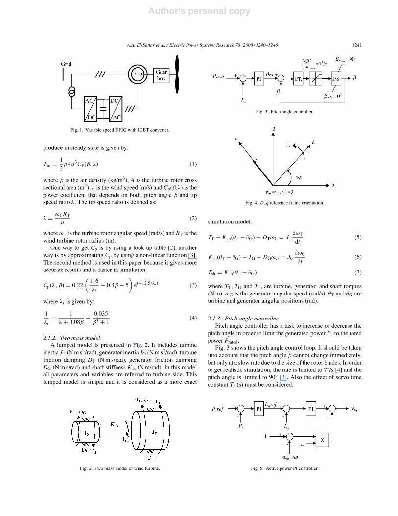
The general turbine model with DFIG is shown in Fig. 1.This model consists of a wind turbine, gearbox and a DFIGwith IGBT converter connected between rotor winding and gridthrough three phase injecting transformer.
2.1. Turbine model
The turbine model consists of number of sub-models includ-ing aerodynamic model, two mass model and pitch anglecontroller model.
2.1.1. Aerodynamic modelThe aerodynamic model of a wind turbine is determined by
its power speed characteristics [1,9]. For a horizontal axis windturbine, the mechanical power output Pm (w) that a turbine can
0378-7796/$ – see front matter © 2007 Elsevier B.V. All rights reserved.doi:10.1016/j.epsr.2007.10.005
Author's personal copy
A.A. El-Sattar et al. / Electric Power Systems Research 78 (2008) 1240–1246 1241
Fig. 1. Variable speed DFIG with IGBT converter.
produce in steady state is given by:
Pm = 1
2ρAu3CP(β, λ) (1)
where ρ is the air density (kg/m3), A is the turbine rotor crosssectional area (m2), u is the wind speed (m/s) and Cp(β,λ) is thepower coefficient that depends on both, pitch angle β and tipspeed ratio λ. The tip speed ratio is defined as:
λ = ωTRT
u(2)
where ωT is the turbine rotor angular speed (rad/s) and RT is thewind turbine rotor radius (m).
One way to get Cp is by using a look up table [2], anotherway is by approximating Cp by using a non-linear function [3].The second method is used in this paper because it gives moreaccurate results and is faster in simulation.
Cp(λ, β) = 0.22
(116
λi
− 0.4β − 5
)e(−12.5/λi) (3)
where λi is given by:
1
λi
= 1
λ + 0.08β− 0.035
β3 + 1(4)
2.1.2. Two mass modelA lumped model is presented in Fig. 2. It includes turbine
inertia JT (N m s2/rad), generator inertia JG (N m s2/rad), turbinefriction damping DT (N m s/rad), generator friction dampingDG (N m s/rad) and shaft stiffness Ksh (N m/rad). In this modelall parameters and variables are referred to turbine side. Thislumped model is simple and it is considered as a more exact
Fig. 2. Two mass model of wind turbine.
Fig. 3. Pitch angle controller.
Fig. 4. D, q reference frame orientation.
simulation model.
TT − Ksh(θT − θG) − DTωT = JTdωT
dt(5)
Ksh(θT − θG) − TG − DGωG = JGdωG
dt(6)
Tsh = Ksh(θT − θG) (7)
where TT, TG and Tsh are turbine, generator and shaft torques(N m), ωG is the generator angular speed (rad/s), θT and θG areturbine and generator angular positions (rad).
2.1.3. Pitch angle controllerPitch angle controller has a task to increase or decrease the
pitch angle in order to limit the generated power Ps to the ratedpower Prated.
Fig. 3 shows the pitch angle control loop. It should be takeninto account that the pitch angle β cannot change immediately,but only at a slow rate due to the size of the rotor blades. In orderto get realistic simulation, the rate is limited to 7◦/s [4] and thepitch angle is limited to 90◦ [3]. Also the effect of servo timeconstant Ts (s) must be considered.
Fig. 5. Active power PI controller.
Author's personal copy
1242 A.A. El-Sattar et al. / Electric Power Systems Research 78 (2008) 1240–1246
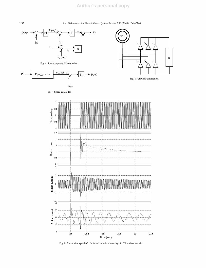
Fig. 6. Reactive power PI controller.
Fig. 7. Speed controller.
Fig. 8. Crowbar connection.
Fig. 9. Mean wind speed of 12 m/s and turbulent intensity of 15% without crowbar.
Author's personal copy
A.A. El-Sattar et al. / Electric Power Systems Research 78 (2008) 1240–1246 1243
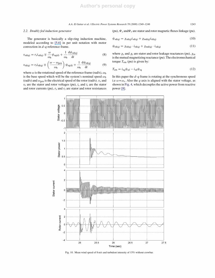
2.2. Doubly fed induction generator
The generator is basically a slip-ring induction machine,modeled according to [5,6] in per unit notation with motorconvection in d–q reference frame.
vsd(q) = rsisd(q) ∓ ω
ωbψsq(d) + 1
ωb
dψsd(q)
dt(8)
vrd(q) = rrird(q) ∓(
ω − ωgen
ωb
)ψrq(d) + 1
ωb
dψrd(q)
dt(9)
where ω is the rotational speed of the reference frame (rad/s), ωbis the base speed which will be the system’s nominal speed ωS(rad/s) and ωgen is the electrical speed of the rotor (rad/s). vs andvr are the stator and rotor voltages (pu), is and ir are the statorand rotor currents (pu), rs and rr are stator and rotor resistances
(pu), Ψ s andΨ r are stator and rotor magnetic fluxes linkage (pu).
ψsd(q) = χsd(q)isd(q) + χmd(q)ird(q) (10)
ψrd(q) = χrd(q) · ird(q) + χmd(q) · isd(q) (11)
where χs and χr are stator and rotor leakage reactances (pu), χmis the mutual magnetizing reactance (pu). The electromechanicaltorque Tem (pu) is given by:
Tem = isqψsd − isdψsq (12)
In this paper the d–q frame is rotating at the synchronous speedi.e ω = ωs. Also the q axis is aligned with the stator voltage, asshown in Fig. 4, which decouples the active power from reactivepower [8].
Fig. 10. Mean wind speed of 8 m/s and turbulent intensity of 15% without crowbar.
Author's personal copy
1244 A.A. El-Sattar et al. / Electric Power Systems Research 78 (2008) 1240–1246
According to Fig. 4, the stator active power Ps and reactivepower Qs are expressed as follows:
Ps = vsqisq (13)
Qs = vsqisd (14)
Also the rotor active power Pr and reactive power Qr areexpressed as follows:
Pr = vrqirq + vrdird (15)
Qr = vrqirq − vrdird (16)
2.3. Rotor side converter controllers
Rotor side converter is modeled as a voltage source converter.The switching dynamics of IGBT switches are neglected [4,7].
These controllers are used to control the active and reactivepower output independently.
As shown in Fig. 5, the stator active power reference Psref(which is determined by the speed controller) is compared withPs to control the stator active power and the output is rotor cur-rent reference Irqref Irqref is then, compared with Irq to get the qcomponent current control loop. According to Eq. (9) the decou-pling term, is added as shown in Fig. 5, to compensate the effectof Ψ rd on vrq.
Fig. 6 shows reactive power controller with decoupling tocompensate the effect of Ψ rq on vrd.
The stator reactive power reference Qsref (which is deter-mined by dispatch center) is compared with Qs to control thestator reactive power and the output rotor current reference IrdrefIrdref is then compared with Ird to get the d component currentcontrol loop. Also according to Eq. (9) the decoupling term isadded to compensate the effect of Ψ rq on vrd.
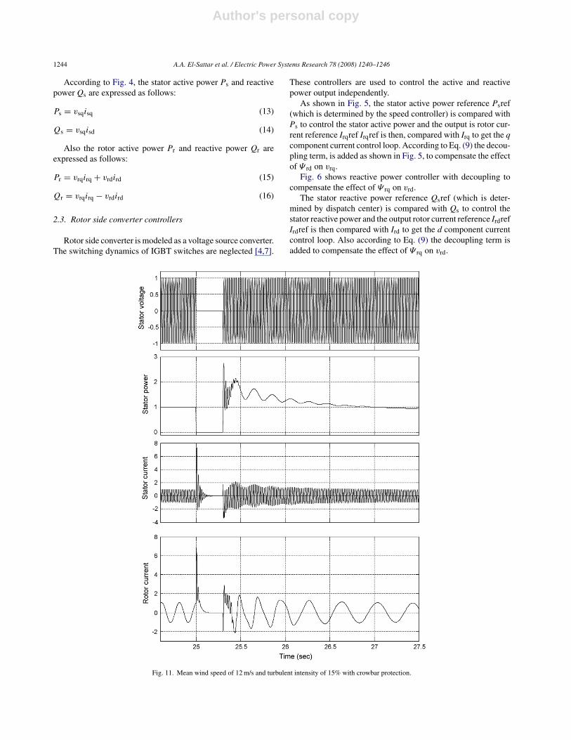
Fig. 11. Mean wind speed of 12 m/s and turbulent intensity of 15% with crowbar protection.
Author's personal copy
A.A. El-Sattar et al. / Electric Power Systems Research 78 (2008) 1240–1246 1245
2.4. Speed controller
Speed controller is slower than active power controllerbecause the mechanical time constant is larger than the elec-trical time constant. The output of the controller is the referencevalue Psref to the active power controller as shown in Fig. 7.
The reference generator speed ωgenref is determined fromPs–ωgen curve which takes Ps as an input, then ωgenref is com-pared with ωgen to control the generator speed.
2.5. Crowbar
The crowbar circuit used in simulations consists of threephase full controlled converter bridge that inserts a resistanceR in the rotor circuit during fault as shown in Fig. 8.
The thyristors are turned on when the rotor current exceedsits maximum value. In the same time the rotor circuit is dis-connected from the rotor side converter and connected to thecrowbar. The rotor remains connected to the crowbar until thefault is cleared or the main circuit breaker disconnects the statorfrom the network.
3. Simulation results
Different cases are simulated to study the response of vari-able speed wind turbine and its control when subjected to threephase short circuit at the generator bus (worst case). The dynamicsimulation is not affected by the wind profile because it can beconsidered constant during the fault period.
3.1. Transient response without crowbar
The analysis was carried out in MATLAB/SIMULINK envi-ronment. A variable step solver is used with maximum step sizeof 1e-3 and minimum step size of 1e-4.
Fig. 9 shows the response of stator power and stator androtor currents for average wind speed of 12 m/s and turbulenceintensity of 15%.
The 3-phase short circuit has been introduced at time instant25 s. The fault has been modeled by a stator voltage reductiondown to zero for a time of 0.3 s.
The stator power due to the occurrence of fault first decreasesto zero, then after clearing the fault it rapidly rises in the positive
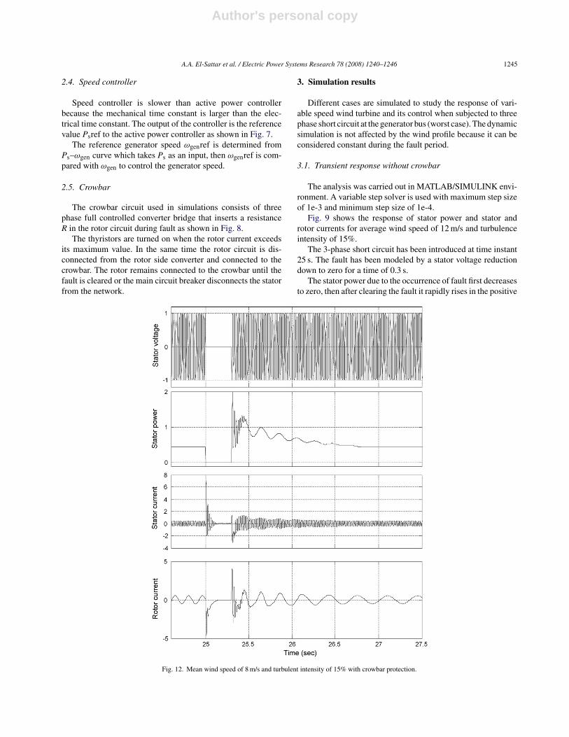
Fig. 12. Mean wind speed of 8 m/s and turbulent intensity of 15% with crowbar protection.
Author's personal copy
1246 A.A. El-Sattar et al. / Electric Power Systems Research 78 (2008) 1240–1246
direction up to 2.5 pu and then starts to oscillate until it reachesits steady state value before fault.
A high transient stator current due to the occurrence of faultfirst increases to 2.5 pu, then after clearing the fault it increasesnegatively to −2.5 pu and then starts to decay until it reaches itssteady state value before fault.
The rotor current due to the occurrence of fault first increasesto 3.5 pu, then after clearing the fault it increases negatively to−3 pu and then starts to decay until it reaches its steady statevalue before fault.
Another case study for a three phase fault is shown in Fig. 10for average wind speed of 8 m/s and turbulence intensity of 15%.
Similar results are obtained at wind speed of 8 m/s.
3.2. Transient response with crowbar
Fig. 11 shows the transient response for the same fault andthe same time duration with crowbar protection. The averagewind speed is 12 m/s and 15% turbulent intensity.
The simulated transients of stator current, rotor current andstator power are when the crowbar protection is implemented asshown in Fig. 8.
The high transient currents in the rotor with a peak valuemore than 7 pu causes the protection to disconnect the rotorfrom the frequency converter. At the same time, the rotor circuitis connected to the crowbar by turning on the crowbar thyristors.The high transient rotor current rapidly decays down to about1 pu.
In comparison with the previous case the stator power firstincreases in positive direction up to 2.8 pu and then starts tooscillate. The stator is reconnected to the network at the time25.3 s after clearing the fault.
Fig. 12 shows another case for average wind speed of 8 m/sand turbulence intensity of 15%.
4. Conclusion
Transient behavior of a DFIG variable speed wind turbineconnected to the network and controlled by vector controlhas been studied. The transient simulation results are for a2 MW DFIG under a three-phase short circuit at the generatorbus.
The results show that the stator and rotor transient cur-rents increase rapidly to value with amplitude more than 1 pu.So the rotor circuit converter must be protected against theincrease in the rotor current. Simulation results also show thatthe amplitude of transient stator power is reduced when thefault occurs. On the other hand, the stator power oscillates afterthe fault is cleared until it reaches steady state value beforefault.
Comparison shows that when the crowbar is implemented,the stator and rotor transient current decay rapidly to value withamplitude less than 1 pu and rotor circuit is properly protected.Simulation results also show that the amplitude of transient statorpower is reduced when the crowbar is activated.
Appendix A
A.1. Base values
P = 2 MW, V = 690 V, f = 50 Hz.
A.2. Wind turbine data
Prated = 2 MW, number of blades = 3, RT = 37.5 m, JT = 2.5 s,Ksh = 2.5 pu/rad, Ts = 1 s, cut in speed = 3 m/s, cut outspeed = 25 m/s, ρ = 1.225 Kg/m3, gear box ratio 1:94.
A.3. DFIG data
JG = 0.5 s, number of poles = 4, rs = 0.048 pu, rr = 0.018 pu,χs = 0.075 pu, χr = 0.12 pu, χm = 3.8 pu.
References
[1] V. Akhmatov, Analysis of dynamic behavior of electric power system withlarge amount of wind turbine, Ph.D. thesis, Orsted DTU, pp. 26–28, 30, 31,2003.
[2] A. Perdana, O. Carlson, J. Persson, Dynamic response of grid connectedwind turbine with doubly fed induction generator during disturbances, in:Nordic workshop on power and industrial electronics, Trondheim, March,2004, pp. 1–6.
[3] J.G. Slootweg, S.W.H. de Haan, H. Polinder, W.L. Kling, General modelfor representing variable speed wind turbines in power system dynamicsimulation, IEEE Trans. Power Sys. 18 (2003) 144–151.
[4] S. Muller, M. Deicke, Rik. W, Doubly fed induction generator systems forwind turbines, IEEE Ind. Appl. Mag. (2002) 26–33.
[5] R.G. de Almeida, J.A. Pecas Lopes, J.A.L. Barreiros, Improving power sys-tem dynamic behavior through doubly fed induction machine controlled bystatic converter using fuzzy control, IEEE Trans. Power Sys. 19 (4) (2004)1942–1950.
[6] F. Poitiers, M. Machmoun, R. Le Doeuff, M.E. Zaim, Control of a Doubly-fed Induction Generator for Wind Energy Conversion Systems, EcolePolytechnique de l’Universite de Nantes, Saint Nazaire, France, 2001,pp.1–6.
[7] J. Soens, J. Driesen, R. Belmans, A comprehensive model of a doubly fedinduction generator for dynamic simulation and power system studies, in:International Conference on Renewable Energies and Power Quality, Vigo,Spain, April, 2003, pp. 1–7.
[8] J. Soens, V. Van Thong, J. Driesen, R. Belmans, Modeling wind turbine gen-erators for power system simulations, in: European Wind Energy ConferenceEWEC, Madrid, Spain, June, 2003, pp. 1–6.
[9] F. Iov, A. Daniela Hansen, P. Sorensen, F. Blaabjerg, Wind Turbine Block-set in Matlab/Simulink, Aalborg University and RISØ National Laboratory,2004.


