Embed Size (px)
Citation preview
University of Nebraska - LincolnDigitalCommons@University of Nebraska - LincolnHistorical Materials from University of Nebraska-Lincoln Extension Extension
1967
EC67-760 How to Adjust Vertical Turbine Pumpsfor Maximum EfficiencyH. Robert Mulliner
John J. Sulek
Follow this and additional works at: http://digitalcommons.unl.edu/extensionhist
This Article is brought to you for free and open access by the Extension at DigitalCommons@University of Nebraska - Lincoln. It has been accepted forinclusion in Historical Materials from University of Nebraska-Lincoln Extension by an authorized administrator of DigitalCommons@University ofNebraska - Lincoln.
Mulliner, H. Robert and Sulek, John J., "EC67-760 How to Adjust Vertical Turbine Pumps for Maximum Efficiency" (1967). HistoricalMaterials from University of Nebraska-Lincoln Extension. 3826.http://digitalcommons.unl.edu/extensionhist/3826
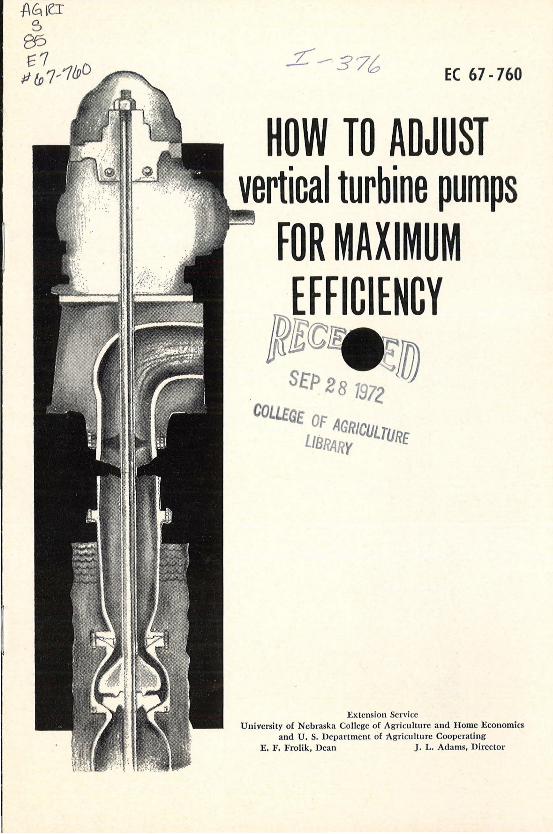
EC 67-760
HOW TO ADJUST vertical turbine pumps
FOR MAXIMUM EFFICIENCY
S£p 2 8 1972 'llJJ COLLEGE
L:RA~:ICULTURE
Extension Service University of Nebraska College <>f Agriculture and Home Economics
and U. S. Department of Agriculture Cooperating E. F. Frolik, Dean J. L. Adams, Director
·.
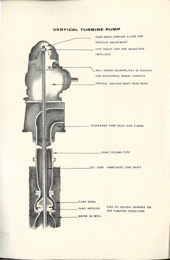
VERTICAL TURBINE PUMP
PUMP SHAFT, THREAD S ALLOW FOR
IMPELLER ADJUSTMENT
LINE SHAFT NUT FOR ADJUSTING
IMPELLERS
BALL THRUST BEARING,MAY BE STACKED
FOR ADDITIONAL THRU ST CAPACITY
'---------DISCHARGE PUMP BASE AND ElBOW
!-._ ____________ PUMP COLUMN PIPE
_________ viL TUBE LUBRICATES LINE SHAFT
_____ PUMP BOWL
'-----PUMP IMPELLER
_____ WATER IN WELL
SIZE OF DESIGN DEPENDS ON
THE PUM.PING CONDITION
How To Adjust Vertical Turbine Pumps For Maximum Efficiency
By H . Robert Mulliner John J. Sulekl
REASONS FOR IMPELLER ADJUSTMENT Fifty-eight percen t of 11 4 irriga tion wells tested by University of
Nebraska College of Agriculture engineers used from 1 1j 3 to 2 times the amount of fuel required .
Part of this waste was ca used by the pump, either from worn impeller seals caused by pumping fin e sands in the water or by improper impeller adjustment.
Faulty adjustmen t ca n reduce the effi ciency of turbine pumps causing use of more fuel and producing less water. Less water lowers total productivity of the pumping unit.
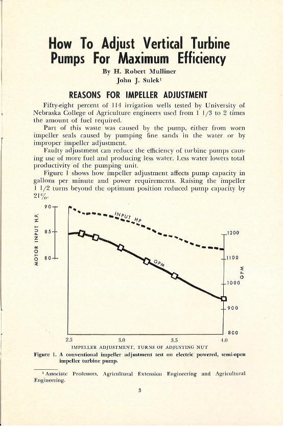
Figure 1 shows how impeller adjustment affects pump capaci ty in ga llons per minu te and power requirements. R aising the impeller 1 l j2 turns beyond the optimum position reduced pump capacity by 21% .
.... ::::l 0..
z IX 0
90
85
0 8 0 ~
...... -•••.,. INp .... ur ._.
.__~,p ..... .., --- .... 1200
-- .... ... __ _ 1100
1000
900
800
25 3~ 35 4 ~
I MPELLER ADJ USTMENT, TU R NS OF ADJ USTING NUT
~ 0..
(!)
F igure 1. A conventional impeller adjustment test on electric powered, semi-open impeller turbine pump.
1 Associate P rofessors, Agricultural Extension E ngineering and Agricultural E ngi neering.
3
Faulty adjustment can ser iously damage impellers and bo·wls regardless of the type. Damage will occur when the impeller rubs either the top or bottom of the bowl.
CONSTRUCTION OF TURBINE PUMPS The turbine irrigation pump consists of one or more impellers
enclosed within a bowl. ·when a typical impeller is rotated by the application of torque to the line shaft, water going through the impeller is accelerated to about 50 miles per hour. This velocity produces about 50 feet of li ft per impeller or stage.
The line shaft extends from the bowl assembly to the top of the pump. It supplies t<;>rque to the impeller, provides support for the mechanical weight of the impeller, and supports the hydrau lic downthrust acting upon the impeller.
Hydraulic downthrust is the force caused by the weight of the water being lifted and pressure against which it is pumped. T he shaft and impeller weight also help to counteract upthrust.
Upthrust is a momentary upward force created in vertical turbine pumps the instant the unit is started. Upthrust is counteracted by clownthrust as soon as the pump and discharge system are lllled with water.
The line shaft may either be enclosed in a tube and oil lubricated or exposed and water lubricated. The nut on the head shaft provides up and clown adjustment for positioning the impeller within the bowl.
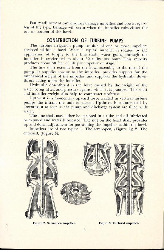
Impellers are of two types: 1. The sem i-open, (Figure 2); 2. The enclosed, (Figure 3).
Figm·e 2. Semi-open impeller. Figure 3. Enclosed impeller.
4
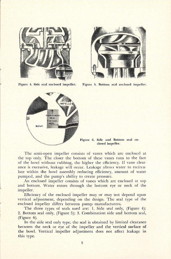
Figure 4. Side seal enclosed impeller. Figure 5. Bottom seal enclosed impeller.
Fig·ure 6. Side and Bottom seal enclosed impeller.
The semi-open impeller consists of vanes which are enclosed at the top on ly. The closer the bottom of these vanes runs to the face of the bowl without r ubbing, the higher the effic iency. If vane clearance is excessive, leakage wi ll occur. Leakage allows water to recirculate within the bowl assembly reducing efficiency, amount of water pumped, and the pump's ab ility to create pressure.
An enclosed impeller consists of vanes which are enclosed at top and bottom. \Vater enters through the bottom eye or neck of the impeller.
Efficiency of the enclosed impeller may or may not depend upon vertical adjustment, depending on the design. The seal type of the enclosed impeller differs between pump manufacturers .
The three types of seals used are: 1. Side seal only, (Figure 4); 2. Bottom seal only, (Figure 5); 3. Combination side and bottom seal, (Figure 6).
In the side seal only type, the seal is obtained by limited clearance between the neck or eye of the impeller · and the vertical surface of the bowl. Vertical impeller adjustment does not affect leakage in this type.
5
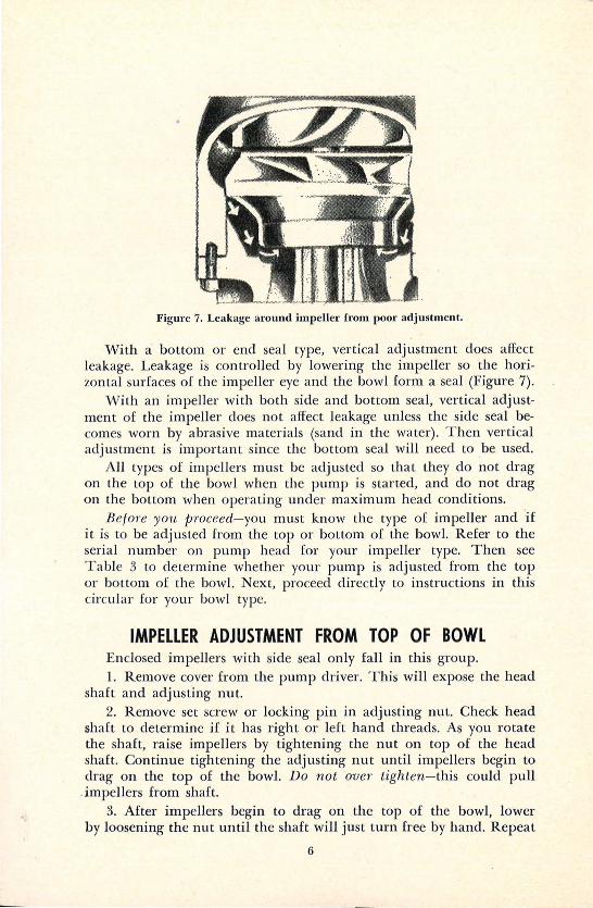
Figure 7. Leakage around impeller from poor adjustment.
With a bottom or end seal type, vertical adjustment does affect leakag-e. Leakag-e is controlled by lowering- the impeller so the horizontal surfaces of the impeller eye and the bowl form a seal (Fig-ure 7).
'!\lith an impeller with both side and bottom seal, vertical adjustment of the impeller does not affect leakage unless the side seal becomes worn by abrasive materials (sand in the water). Then vertical adjustment is important since the bottom seal will need to be used.
All types of impellers must be adjusted so that they do not drag on the top of the bowl when the pump is started, and do not drag on the bottom when operating under maximum head conditions.
BejoTe you pmceed-you must know the type of impeller and ·if it is to be adjusted from the top or bottom of the bowl. Refer to the serial number on pump head for your impeller type. Then see Table 3 to determine whether your pump is adjusted from the top or bottom of the bowl. Next, proceed directly to instructions in this circular for your bowl type.
IMPELLER ADJUSTMENT FROM TOP OF BOWL Enclosed impellers with side seal only fall in this group. l. Remove cover from the pump driver. This will expose the head
shaft and adjusting nut. 2. Remove set screw or locking pin in adjusting nut. Check head
shaft to determine if it has right or left hand threads. As you rotate the shaft, raise impellers by tig-htening the nut on top of the head shaft. Continue tightening the adjusting nut until impellers begin to drag on the top of the bowl. Do not over tighten-this could pull
. impellers from shaft. 3. After impellers begin to drag on the top of the bowl, lower
by loosening the nut until the shaft will just turn free by hand. Repeat
6
this procedure several times to be sure of the position. Mark position of adjusting nut at this point.
4. Loosen the nut one fu ll turn from position marked in Step 3 and replace set screw. Check operators manual for recommendations for any additional clearance recommended by the p ump manufacturer.
5. Rotate impellers to make sure they are turning free before test running.
6. Operate pump. On units powered with internal combustion engines, start the pump slowly and increase speed gradually until desired speed and maximum pumping head are obtained. During this runup, listen and watch closely for unusual noises or vibrat ions. If they o.ccur, shut clown uni t and recheck procedure for error. Observe pump operations un til drawdown and discharge pressure are stabilized.
Recheck Setting of Impellers
T he procedure described under adjustment from top of bowl . should give maximum efficiency. However, impeller adjustment should be rechecked after about 50 hours of operation. Shaft couplings may have tightened during pumping, causing a shortening of the line shaft. In such cases, readjusting to original clearance may be required.
ADJUSTMENT FROM BOTTOM OF BOWL Impellers which normally fa ll in this group are the semi-open, the
enclosed with side and bottom seal, and the enclosed with bottom seal only. See Table 3 for information on pumps and impellers adjusted from the bottom.
Calculate Preliminary Impeller Adjustment
J. Impeller make and bowl number (check name plate on your pump).
2. Downthrust in pounds per feet of head (See Table 3). 3. Shaft diameter, and length (measure shaft diameter. For shaft
length, see pump order sheet). 4. Total pumping head. Measure by checking:
a. Lift (depth to water from pump head when pumping). b. Discharge pressure (from pressure gauge) . Convert to feet of
head by multiplying pounds of pressure by 2.31. c. Add the lift and discharge pressure to get the total pumping
head. 5. Threads per inch of line shaft.
7
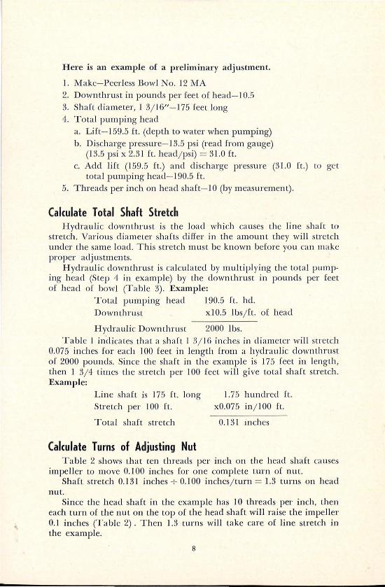
Here is an example of a preliminary adjustment.
l. Make-Peerless Bowl No. 12 MA 2. Downthrust in pounds per feet of head-10.!1 3. Shaft diameter, 1 3j 16"-175 feet long 4. Total pumping head
a. Lift-159.5 ft. (depth to water when pumping) b. Discharge pressure-13.5 psi (read from gauge)
(13.5 psi x 2.31 ft. headj psi) = 31.0 ft. c. Add lift (159.5 ft.) and discharge pressure (31.0 ft.) to get
total pumping head- 190.5 ft. 5. Threads per inch on head shaft- 10 (by measurement) .
Calculate Total Shaft Stretch Hydraulic downthrust is the load which ca uses the line shaft to
stretch. Various diameter shafts differ in the amount they will stretch under the same load . This stretch must be known before you can make proper adj ustments .
Hydraulic clownthrust is calculated by multiplying the total pumping head (Step 4 in example) by the downthrust in pounds per feet of head of bowl (Table 3). Example:
Total pumping head 190.5 ft . hd. Downthrust x10.5 lbs j ft. of head
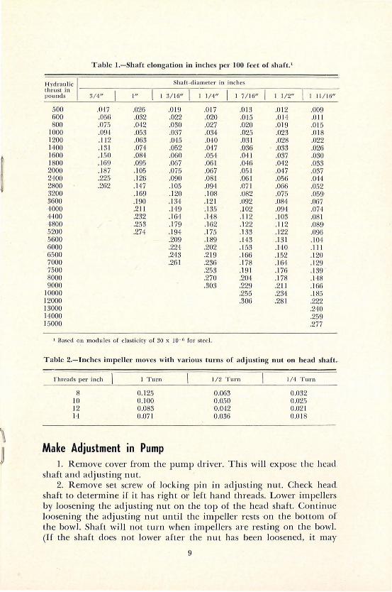
Hydraulic Down thrust 2000 lbs. Table I indicates that a shaft J 3j l6 inches in diameter will stretch
0.075 inches for each I 00 feet in length from a hydraulic down thrust of 2000 pounds. Since the shaft in the example is 175 feet in length, then 1 3j 4 times the stretch per 100 feet will give total shaft stretch. Example:
Line shaft is 175 ft. long Stretch per I 00 ft.
Total shaft stretch
Calculate Turns of Adjusting Nut
1.75 hundred ft. x0.075 in j lOO ft.
0.131 in ches
Table 2 shows that ten threads per inch on the head shaft causes impeller to move 0.100 inches for one complete turn of nut.
Shaft stretch 0.131 inches...;- O.JOO inchesj turn = 1.3 turns on head nut.
Since the head shaft in the example has 10 threads per inch, then each turn of the nut on the top of the head shaft will raise the impeller 0.1 inches (Table 2). Then 1.3 turns will take care of line stretch in the example.
8
.~
Table I.-Sh aft e longation in inches per 100 fee t of sh aft. 1
H ydra ulic I Shaft -d iameter in inches lhru st in l pounds 3/ 4" I " I 3/16" I 1/ 4" I 7/16" I 1/2" I 11 / 16"
500 .047 .026 .0 19 .017 .0 13 .012 .009 600 .056 .032 .022 .020 .0 15 .014 .Oil 800 .075 .0<12 .030 .027 .020 .019 .0 15
1000 .094 .053 .037 .034 .025 .023 .0 18 1200 .1 12 .063 .045 .Q<JO .031 .028 .022 1400 .1 31 .07<1 .052 .0<17 .036 .033 .026 1600 .150 .084 .060 .054 .0<1 1 .037 .030 1800 .1 69 .095 .067 .061 ,0<}6 .042 .033 2000 .1 87 .105 .075 .067 .051 .047 .037 2400 .225 .126 .090 .081 .061 .056 .044 2800 .262 .H 7 .105 .09<1 .07 1 .066 .052 3200 .1 69 .1 20 .108 .082 .075 .059• 3600 .190 .134 .12 1 .092 .084 .067 '1000 .211 .149 .135 .102 .094 .074 4400 .232 .16<1 .1 48 . I 12 .I 03 .081 4800 .253 .1 79 .162 .122 .I 12 .089• 5200 .274 .1 94 .175 .I 33 .122 .096 5600 .209 .189 .1 43 .1 3 1 .10<1 6000 .22<1 .202 .. 153 .140 .111 6500 .243 .219 .166 .1 52 .1 20 7000 .26 1 .236 .1 78 .164 . 129 7500 .253 .191 .176 .139 . 8000 .270 .204 .1 78 .I <18 9000 .303 .229 .211 .166
10000 .255 .234 .1 85 12000 .306 .28 1 .222 13000 .2<10 14000 .259 15000 .277
' Uascd on modn lcs o f c lasLicily o [ 30 x 10- 0 [or steel.
Table 2.-Jnch es impeller moves with various turns of adjusting nu t on h ead sh aft ..
rtucads per inch
8 10 12 14
I T u rn
0.125 0.100 0.083 0.071
Make Adjustment in Pump
1/ 2 T um
0.063 0.050 0.042 0.036
I / 4 T urn
0.032 0.025 0.02 1 0.018
I . R emove cover from the p ump driver. T his will expose the head. shaft and adjust ing nu t.
2. R emove set screw of locki ng p in in adjusting nu t. Check head shaft to determine if it has righ t or left hand th reads. Lower impellers. by loosening the adjusting nu t on the top of the head shaft. Continue loosening the adjusting nut until the impeller r es ts on the bo ttom of the bowl. Shaft will not turn when impellers are res ting on the bowl. (If the shaft does not lower after the nu t has been loosened, it may
9
be necessary to hit the shaft on top. (Use wooden block to avoid damage to the threads.)
3. Raise impellers by tightening the adjusting nut until the shah will just turn free by hand. Mark the position of adjusting nut at this point. Repeat the procedure several times to be sure of this position.
4. Tighten adjusting nut the amount calculated (in this example, 1.3 turns beyond the marked point). Check operators manual to be sure the calculated adjustments do not exceed manufacturers vertical bowl clearance. Tighten set screw. This will be the preliminary setting for the impellers.
5. Rotate impellers to make sure they are turning free before test running.
6. Operate the pump. On units powered with internal combustion .engines, start the pump slowly and increase speed gradually until .desired speed and maximum pumping head are obtained. During this runup, listen and watch closely for unusual noises or vibrations. If they occur, shut clown unit and recheck procedure for error. Observe pump operation until drawdown and discharge pressure are stabilized.
On electrically powered units a gradual speed increase cannot be -obtained, but you should listen and watch closely for unusual noises or vibrations.
Recheck Setting of Impellers New pumping installations are usually pumped 50 to 100 hours
before final impeller adjustments are made. This allows for the shaft .couplings to tighten and most abrasives such as fine sands to be removed from the wells. On older installations, adjustments are made to correct for impeller and seal wear which might have decreased the ·efficiency of the pump.
l. Use the shaft elongation figures as determined under preliminary .adjustment and make proper adjustment.
2. Unit should then be brought up to stabilized maximum head .conditions and one or all of the following items observed after draw·down is stabilized.
a. Discharge in gallons per minute for both engines and electric motors.
b. Electrical imput if electric motor used. Use stop watch and count revolutions of electric meter; or use the clip-on ammeter for indicating the change in power requirement.
3. Stop pump and make a slight change of impeller setting by •lowering l j 6 turn on adjusting nut.
4. Start pump and check for abnormal sounds or vibrations. Stop unit immediately if abnormal sounds or vibrations occur. A sound detecting device similar to the stethoscope is useful.
10
5. R epeat procedures described under Step 2. Maximum efficiency se tting will be reached just before a sharp increase in noise level (determined by a sounding device) or a sudden increase in power requirement. This impeller setting will also give the greatest gpm .and highest total head.
The imput horsepower curve in Figure 1 illustrates this sudden increase in horsepower requirements. In this case, when the semi-open impeller was set too close (dragging on the bottom) power requirements jumped with no increase in pump discharge capacity.
FREQUENCY OF ADJUSTMENT On new pumping installations, preliminary adjustments should be
made when the new pump is installed. The recheck adjustment is then made after the unit has operated from 50 to 100 hours. Annual rechecks should be made until the pump and well have been stabilized.
On older installations, adjusting may help return the pump to original efficiency. The frequency of adjustment of older pumps will depend upon the amount of abrasive material being carried in the water. Some pumps in Nebraska operating in sand-free water have retained their original efficiency after 9000 hours of pumping.
If foT some Teason majo1· iriC1'eases in head are planned, new adjustments must be made with pumps which have impellen adjusted fmm the bottom.
DIAGNOSIS OF IMPELLER DAMAGE \1\lhen the bowl assembly is removed for repairs, impellers should
be inspected to see if they were damaged because of incorrect adjustment. It may be necessary to have the pump redesigned to remove the causes of the damage.
Top damage may be caused by the shaft coupling tightening during pumping, or may be due to improper original adjustment. In some cases, momentary upthrust when starting the pump may cause the failure. A special thrust bearing must be used to provide thrust protection in these pumps.
Bottom damage may be due to errors in calculating shaft elongations. Bottom damage may also be clue to increases in total pumping head over what had been used in the original design and adjustments. The increase in head may be caused by using a higher pump speed; a lowering of water table in the well; or a change from the original discharge systems.
A common change is the addition of a gated pipe distribution system to a pump which was designed for open discharge.
Also, over-pumping of a well can start sand pumping which will damage both the seals and impeller vanes.
11
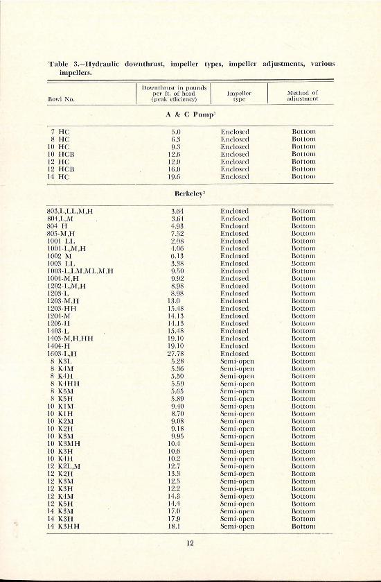
Table 3.-Hydrau1ic downthrust, impeller types, impeller adjustments, various impellers.
llowl No.
7 HC 8 HC
10 HC: 10 HCB 12 H C: 12 HCB 14 HC:
803,L,LL,M,H 804,L,M 804 H 805-M,H 1001 LL 1001 -L,M,H 1002 M 1003 LL 1003-L,LM,ML,M,H 1004-M,H 1202-L,M,H 1203-L 1203-M,H 1203-HH 1204-M 1205-H 1403-L 1403-M,H,HH 1404-H 1603-L,H 8 K3L 8 K4M 8 K4I-I 8 K4HH 8 K5M 8 K5H
10 KIM 10 K1H 10 K2M 10 K2H 10 K3M 10 K3MH 10 K3H 10 K4H 12 K2L,M 12 K2H 12 K3M 12 K3H 12 K4M 12 K5H 14 K3M 14 K3H 14 K3HH
Downthrust in pounds I per ft . of head (peak eff1 ciency)
A & C Pump1
!5.0 6.3 9.3
12.6 12.0 16.0 19.6
Berkeley"
3.64 3.64 'l-.93 7.52 2.08 4.06 6 .1 3 3.38 9.50 9.92 8.98 8.98
13.0 15.48 14.13 14 .1 3 I 5.48 19.10 19 .1 0 27.78
5.28 5.36 5.50 5.59 5.65 5.89 9.40 8.70 9.08 9. 18 9.95
I 0.4 10.6 10.2 12.7 13.3 12.5 12.2 14.3 14.4 17.0 17 .9 18.1
12
Method of Impeller type adjustment
E nclosed Houom Enclosed Bottom Encl osed Bottom Enclosed Bottom Enclosed Bottom Enclosed Bottom Enclosed Bottom
Enclosed Bottom Enclosed Bottom Enclosed Bottom Enclosed Bottom Enclosed Bottom Enclosed Bottom Enclosed Bottom E nclosed Bottom Enclosed Bottom En closed Bottom Enclosed Bottom E nclosed Bottom Enclosed Bottom Enclosed Bottom Enclosed Bottom Enclosed Bou.om Enclosed Bottom Enclosed Bottom Enclosed Bou:om Enclosed Bottom Semi-open Bottom Sem i-open Bottom Sem i-open Bottom Semi -o pen Bottom Semi-open Bottom Semi-open Bottom Semi-open Bottom Semi -open Bottom Sem i-open Bottom Sem i-open Bottom Sem i-open Bottom Sem i-open Bottom Sem i-open Bottom Sem i-open Bottom Semi -open Bottom Semi-open Bottom Semi-open Bollom Semi-open Bottom Semi -open Bottom Semi -open Bottom Semi-open Bottom Sem i-open Bottom Semi -open Bottom
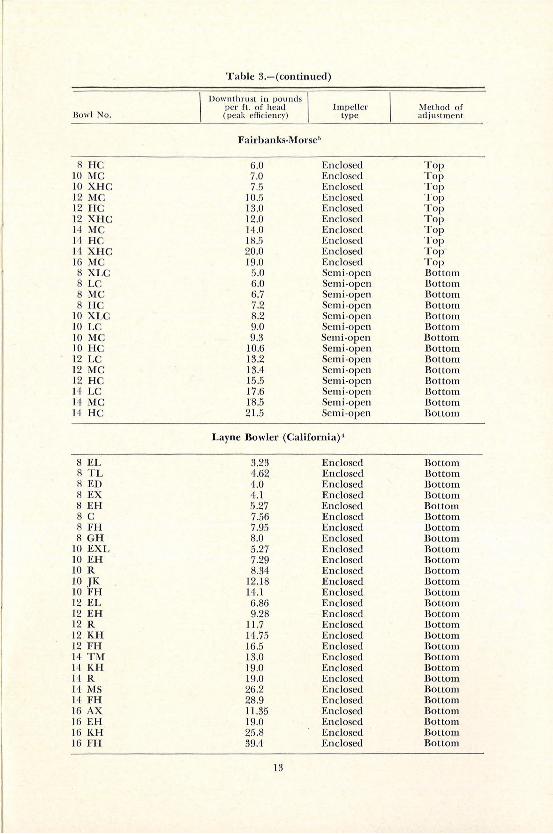
Table 3.-(continued)
Downthrust in pounds I per fL. of head Impell er Method o(
Bowl No. (peak effici e ncy) type adjustment
Fairbanks-Morse''
8 HC 6.0 Enclosed Top 10 MC 7.0 Enclosed Top 10 XHC 7.5 Enclosed Top 12 MC 10.5 Enclosed Top 12 HC 13.0 Enclosed Top 12 XHC 12.0 Enclosed Top 14 MC 14.0 Enclosed Top 14 HC 18.5 Enclosed Top H XHC 20.0 Enclosed Top-16 MG 19.0 Enclosed Top 8 XLC 5.0 Semi-open Bottom 8 LC 6.0 Semi-open Bottom 8 MC 6.7 Semi-open Bottom 8 HC 7.2 Semi-open Bottom
10 XLC 8.2 Semi-open Bottom 10 LC 9.0 Semi-open Bottom 10 MC 9.3 Semi-open Bottom 10 HC 10.6 Semi-open Bottom 12 LC 13.2 Semi-open Bottom 12 MC 13.4 Semi-open Bottom 12 HC 15.5 Semi-open Bottom 14 LC 17.6 Semi-open Bottom 14 MC 18.5 Semi-open Bottom H HC 21.5 Semi-open Bottom
Layne Bowler (Califomia) ·'
8 EL 3.23 Enclosed Bottom 8 TL 4.62 Enclosed Bottom 8 ED 4.0 Enclosed Bottom 8 EX 4.1 Enclosed Bottom 8 EH 5.27 Enclosed Bottom 8 c 7.56 Enclosed Bottom 8 FH 7.95 Enclosed Bottom 8 GH 8.0 Enclosed Bottom
10 EXL 5.27 Enclosed Bottom JO EH 7.29 Enclosed Bottom 10 R 8.34 Enclosed Bottom 10 .JK 12.1 8 Enclosed Bottom 10 FH 14.1 Enclosed Bottom 12 EL 6.86 Enclosed Bottom 12 EH 9.28 Enclosed Bottom 12 R 11.7 Enclosed Bottom 12 KH 14.75 Enclosed Bottom 12 FH 16.5 Enclosed Bottom 14 TM 13.0 Enclosed Bottom 14 KH 19.0 Enclosed Bottom l<lR 19.0 Enclosed Bottom H MS 26.2 Enclosed Bottom I'! FH 28 .9 Enclosed Bottom 16 AX 11.35 Enclosed Bottom 16 EH 19.0 Enclosed Bottom 16 KH 25.8 Enclosed Bottom 16 FH 39.4 Enclosed Bottom
13
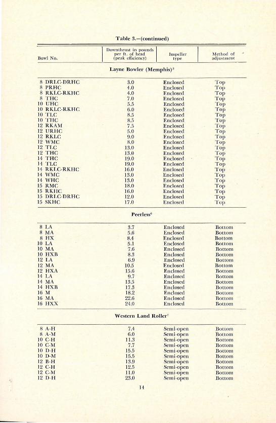
Table 3.-(continued)
Downthntst in pounds I per fl. of head Impeller Meth od of
Bowl No. (peak efficien cy) type adjustm ent
Layne Bowler (Memphis)"
8 DRLC-DRHC 3.0 Enclosed Top 8 PRHC 4.0 Enclosed Top 8 RKLC-RKHC 4.0 Enclosed Top 8 THC 7.0 Enclosed Top
10 UHC 5.5 Enclosed Top 10 RKLC-RKHC 6.0 Enclosed Top 10 TLC 8.5 Enclosed Top 10 THC 8.5 Enclosed Top 12 RKAM 7.5 Enclosed Top 12 URHC 5.0 Enclosed Top 12 RKLC 9.0 Enclosed Top 12 WMC 8.0 Enclosed Top 12 TLC 13.0 Enclosed Top 12 THC 13.0 Enclosed Top 14 THC 19.0 Enclosed Top 14 TLC 19.0 Enclosed Top 14 RKLC-RKHC 16.0 Enclosed Top 14 w:Mc 13.0 Enclosed Top 14 WHC 13.0 Enclosed Top 15 RMC 18.0 Enclosed Top 15 RKHC 16.0 Enclosed Top 15 DRLC-DRHC 12.0 Enclosed Top 15 SKHC 17.0 Enclosed Top
J>eerless0
8 LA 3.7 Enclosed Bottom 8 !viA 5.6 Enclosed Bottom 8 HX 8.4 Enclosed Bottom
10 LA 5.1 Enclosed Bottom 10 MA 7.6 Enclosed Bottom 10 HXB 8.3 Enclosed Bottom 12 LA 6.9 Enclosed Bottom 12 MA 10.5 Enclosed Bottom 12 HXA 15.6 Enclosed Bottom 14 LA 9.7 Enclosed Bottom 14 MA 13.5 Enclosed Bottom 14 HXB 17.3 Enclosed Bottom 16M 18.2 Enclosed Bottom 16 MA 22 .6 Enclosed Bottom 16 HXX 24.0 Enclosed Bottom
'Vestem Land Roller'
8 A-H 7.4 Semi-open Bonom 8 A·M 6.0 Semi-open Bottom
10 C-H 11.3 Semi -open Bottom 10 C-M 7.7 Semi-open Bottom 10 D-H 15.5 Semi-open Bottom 10 D-M 15.5 Semi -open Bottom 12 B-H 13.9 Semi -open Bottom 12 C-H 12.5 Semi-open Bottom 12 C-M 11.0 Semi-open Bottom 12 D-H 23.0 Semi-open Bottom
14
llow l No.
12 X-H 14 C-H 14 C-M 14 D-H 14 D-M 16 0-H
8- 100 & 125 8-120 8-150 & 200 8-225 8-250,300 & 350 10-50 & 80 10-100 1 0-17 5,225,250,300
& 302,350,352 & 400 10-4·02 10-450,500,502,550 10-600 10-602 12-250,300, & 350 12-252 12-352,400 & 450 12-425,500 #1 12-500#2 12-503,503-602,602 12-600 & 700 12-900 12-1000 12-1200 14-250 & 300 14-400,500 & 600 14-700,800,900 14-850,1100 14-1000,1200, & 1202 14-1400 & 1600 16-450,500,650 & 750 16-800 16-1125, & 1350 16-1250 & 1500 16-1750 16-2250
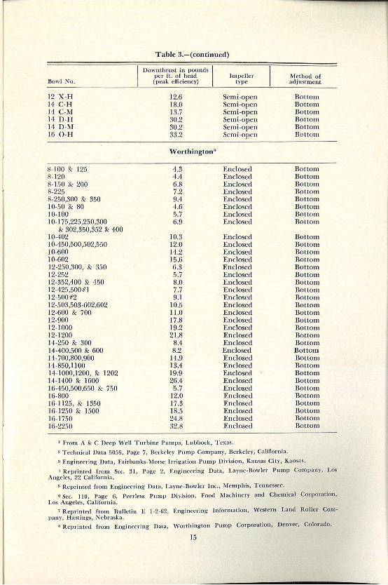
Table 3.-(continued)
Downthrust in pounds l per fl. of head
(peak efficiency)
12.6 18.0 13.7 30.2 30.2 33.2
Worthington•
4.3 4.4 6.8 7.2 9.4 4.6 5.7 6.9
10.3 12.0 14.2 15.6 6.3 5.7 8.0 7.7 9.1
10.5 11.0 17.8 19.2 21.8
8.4 8.2
14.9 13.4 19>.9 26.4 15.7
12.0 17 .3 18.5 24.8 32.8
Impeller type
Semi-open Semi-open Semi-open Semi-open Semi-open Semi -open
Enclosed Enclosed Enclosed Enclosed Enclosed Enclosed Enclosed Enclosed
Enclosed Enclosed Enclosed Enclosed Enclosed Enclosed Enclosed Enclosed Enclosed Enclosed Enclosed Enclosed Enclosed Enclosed Enclosed Enclosed Enclosed Enclosed Enclosed Enclosed Enclosed Enclosed Enclosed Enclosed Enclosed Enclosed
'!'rom A & C Deep Well Turb in e Pumps, Lubbock , Texas .
2 T echn ica l Data 5055, Page 7 , Be rkeley J>ump Company, Berkeley, Cali for ni a.
Method of adjustment
Bottom Bottom Bottom Bottom Bottom Bottom
Bottom Bottom Bottom Bottom Bottom Bottom Bottom Bottom
Bottom Bottom Bottom Bottom Bottom Bottom Bottom Bottom Bottom Bottom Bottom Bottom Bottom Bottom Bottom Bottom Bottom Bottom Bottom Bottom Bottom Bottom Bottom Bottom Bottom Bottom
a Engineering Data, Fairbanks·Morsc Irrigation Pump Division , Kansas City, Kansas .
·I Reprinted from Sec. 3 1, Page 2, Engineering Data , Layne .nowlcr Pump Compa ny, Los Angeles, 22 California.
r. Reprinted from Engineering Data , Layne -Bowler Inc., :Memphis, Tennessee.
o Sec. 110 , Page 6, Peerless Pump Division , Food 1\'Iachinery and Chemical Corporalion , Los Angeles, Cn lifornia.
1 Reprinted from Bulletin E J-2-62 , Engineering Information, Western Land Roller Compa ny, Hastings, Nebraska.
s Reprinted from Engineering Data , ' ·Vorthington Pump Corporation, Denver, Colorado.
15


