Embed Size (px)
Citation preview
JOURNAL OF MATERIALS SCIENCE: 311 (1995) 1601-1608
Effect of morphology on the behaviour of ternary composites of polypropylene with inorganic fillers and elastomer inclusions Part I Tensile yield strength
J. JANCAR Faculty of Chemistry, Technical University Brno, Veslarska 230, 637 11 Brno, Czech Republic
A . T . DIBENEDETTO Institute of Materials Science, University of Connecticut, 97 North Eagleville Road, Storrs, CT 06269-3136, USA
The effects of phase morphology, interfacial adhesion, rigid filler particle shape and elastomer volume fraction on the tensile yield strength of polypropylene (PP) filled with inorganic filler (CaCO3 or Mg(OH)2) and ethylene-propylene elastomer (EPR) were investigated. Separation of the filler and elastomer particles was achieved using maleic- anhydride-grafted PP (MPP) to enhance the f i l ler-matrix adhesion. Encapsulation of the rigid filler by the elastomer was achieved using maleic-anhydride-grafted EPR (MEPR) to increase the fi l ler-elastomer adhesion. The two limiting morphologies differ significantly in mechanical properties under tensile loading at the same material composition. Elastomer particles separately dispersed in the matrix enhance the shear banding in the bulk matrix which prevents the crazes growing from the filler surface from becoming unstable and, thUs, increases the ductility of the material. Encapsulation by an elastomer layer on the filler surface relieves triaxial stresses at the filler surface, changing the major local failure mechanism from crazing to shear yielding and, hence, increasing the ductility of the material. Increase of the elastomer volume fraction also causes, in both cases, an increase in matrix ductility. Composite models are used to predict upper and lower limits of yield strength ((~y) for the two limiting morphologies over an interval of elastomer volume fractions (V e) from 0 to 0.2 at a constant filler loading of 30 vol.% and over a filler volume fraction from 0 tO 0.4 at a constant EPR content in the matrix. Satisfactory agreement was found between the experimental data and theoretical predictions.
1. Introduction Further expansion of the use of high-volume poly- meric materials, such as polypropylene (PP), in engin- eering applications (automotive, home appliances, mass transportation vehicles and construction indus- tries) is dependent on the ability to enhance both their stiffness and toughness. Fire safety concerns bringing about an additional requirement of reduced flamma- bility, especially for those used in the mass transport and construction industries.
The enhancement of PP stiffness is commonly achieved by incorporating rigid fillers or reinforce- ments, while the enhancement of fracture resistance is achieved through a blending with other polymers, mainly elastomers. As has been shown earlier, ternary composites consisting of PP filled with rigid inorganic particles and elastomer inclusions can be designed to be both stiffer and tougher than the neat PP [1]. In addition to the effects of filler and elastomer volume fraction and rigi d particle shape, phase morphology,
0022-2461 �9 1995 Chapman & Hall
i.e., the spatial arrangement of components, plays a crucial role in determining the composite mechan- ical response. Morphology of a ternary composite PP/EPR/filler is a result of a frozen dynamic equilib- rium between thermodynamic and shear forces in the melt during the mixing procedure. The thermodyn- amic forces are determined by the surface free energy of components and the system tends to acquire a mor- phology with minimum total free energy. In the com- posites studied, the free energy of the filler is signifi- cantly greater than that of EPR which is again greater than that of PP I-2]. Thus, the morphology possessing the lowest free energy is when filler particles are encap- sulated by the elastomer layer and these complex core-shell inclusions are embedded in PP. The shear forces are controlled by the relative viscosities, tem- perature, particle size and shape and by other rheological parameters I-2] and tend to remove the elastomer from the filler surface in the course of melt mixing, leading to a separated dispersion of the filler
1601
Non-polar PP and EPR
Random array
0 o o
' o I 0 o
r Perfect sep~ Perfect encapsulation I
~ j I �9 �9
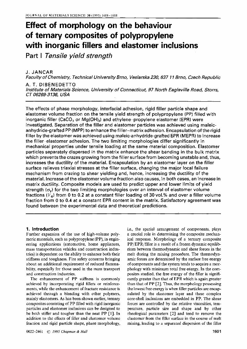
Figure 1 Schematic representation of morphology changes intro- duced by increasing the amount of maleic anhydride (MAH) in the matrix (left) or in the elastomer phase (right). Random array corres- ponds to 0wt.% MAH, i.e., unmodified ternary composite PP/EPR/filler.
and elastomer inclusions. Hence, a random distribu- tion of encapsulated, core-shell, separated filler and elastomer inclusions in the PP matrix is the morpho- logy resulting from an uncontrolled mixing process (Fig. 1). The reproducibility of such a random mor- phology is rather low. Grafting of maleic anhydride (MAH) onto either PP or EPR increases significantly the surface free energy of the respective component and, thus, affects the resulting morphology via modifi- cation of the thermodynamic forces. At some MAH concentration and mixing conditions, the thermodyn- amic forces become dominant in controlling the phase geometry of the ternary composite resulting in two limiting phase geometries - complete separation of the filler from the elastomer (using MAH grafted PP as the matrix) and complete encapsulation of the filler by the elastomer (using MAH grafted EPR as the elas- tomer). An objective of this study is to determine the mechanical properties of materials with these two limiting phase morphologies (Fig. 1).
Kolarik et al. [3-5] and Jancar and DiBenedetto [6] have shown that the two limiting morphologies, i.e., separation of the filler and elastomer inclusions and the encapsulation of the filler by the elastomer, exhibit substantial differences in both stiffness and fracture toughness at the same composition. A model predicting upper and lower limits of elastic moduli was proposed recently by Jancar and DiBenedetto [7]. Although a large amount of experimental data on yielding and fracture behaviour of ternary composites
1602
and blends has been published [8-i0], no clear elu- cidation of the failure mechanics and mechanisms has been reported in the literature.
Halogenated hydrocarbons, phosphorus based flame retardants and inorganic fillers such as alumina trihydrate, AI(OH)3, and magnesium hydroxide, Mg(OH)2, are used in high-volume polymers to min- imize the evolution of dense smoke and acidic poison- ous gases during combustion [11-14]. Incorporation of Mg(OH2) in PP also increases the ignition temper- ature, even at long exposition times [-14]. However, filler loading in the range of 60-80wt.% (0.3 <vf < 0.5), necessary to achieve the required non-flammability, reduces the yield strength and frac- ture toughness of the composite material.
In this paper, the relationship between yielding be- haviour and phase geometry of ternary composites of PP with inorganic fillers and elastomer inclusions is analysed. Existing composite models are utilized to predict the upper and lower limits for the tensile yield strength in the case of the two limiting morphologies of complete separation and encapsulation.
2. Exper imenta l procedure Commercial polypropylene Mosten 58.412 (Litvinov Chemical Works, Czech Republic), melt flow ratio of 4 g 10rain-1 (230 ~ 21.6 N), was used as a matrix. Maleated PP (Research Institute of Macromolecular Chemistry, Brno, Czech Republic), melt flow ratio 20 g 10min- a (230 ~ 21.6 N) and containing 2 wt.% of grafted maIeic anhydride, was used to modify matrix-filler adhesion. PP and maleated PP (MPP) were mixed in a PLO 651 Brabender Plasticorder (190 ~ 50 r.p.m., 10 min) to achieve the required con- centration of carboxyl groups in the matrix.
Ethylene-propylene random copolymer (EPR) Dutral CO 054 (Himont, Italy), T g = - 5 7 ~ Mw = 180000, was used as an elastomer. A maleated version of Dutral CO 054 (RIMC, Brno, Czech Re- public), containing 2wt.% of grafted MAH, was mixed with EPR to achieve the required concentration of carboxyl groups in elastomer under the same condi. tions as described above.
Two batches of platelet shaped Mg(OH)2 filler of the same average aspect ratio of 5, and specific surface area of 7 and 18 m2g -1, respectively, (RIMC, Brno, Czech Republic), were used as flame retardant fillers. Additionally, irregularly shaped CaCOa filler, Durcal 2 (Omya, Switzerland), with average particle diameter of 3.6 gm and specific surface area of 2.5 m 2 g- 1, was used to investigate the effect of particle shape. Only untreated fillers were used to avoid the effects of com- monly utilized commercial surface treatments.
PP/filler/elastomer composites were prepared by mixing all the components in a one step procedure (PLO 651 Brabender Plasticorder, 200~ 50 r.p.m., 10 min). Dog-bone shaped specimens were cut from sheets of the compounded materials which were com- pression moulded at 200 ~ for 4 min at atmospheric pressure and 2 min under 6 MPa and cooled down under pressure at an average cooling rate of 20 ~ min- 1. Yield strength at room temperature was
measured using an Instron 4302 Tensile Tester at a strain rate of 1.0 rain-1. Reported values are aver- aged from five specimens with a standard deviation of the order of 5%.
Fracture surfaces for morphological observations were prepared by breaking, under flexure load in liquid nitrogen, rectangular bars of the material con- taining a sharp razor blade notch. The surface was then etched for 1-5 min in boiling n-heptane to re- move the elastomer. Specimens broken during tensile tests and etched under the same conditions as above were also used. A scanning electron microscope (SEM) Amray IV (Amray, USA) was used to examine the fracture surfaces.
3 . R e s u l t s a n d d i s c u s s i o n
3.1. Separation of the filler and elastomer inclusions
3. 1. 1. Effect o f phase morphology at constant composit ion ([MPP/EPR]/ f i l ler = [60/10]/30 and [60/20]/20)
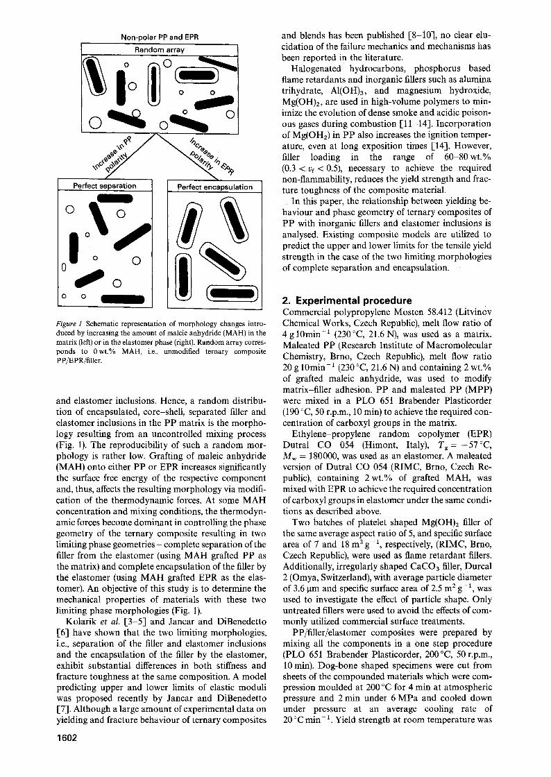
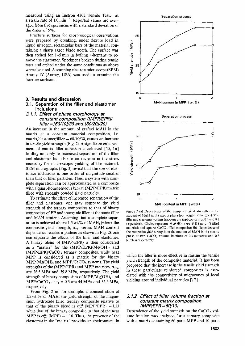
An increase in the amount of grafted MAH in the matrix at a constant material composition, i.e. matrix/elastomer/filler = 60/10/30, causes an increase in tensile yield strength (Fig. 2). A significant enhance- ment of matrix-filler adhesion is achieved [15, 16] leading not only to increased separation of the filler and elastomer but also to an increase in the stress necessary for macroscopic yielding of the material. SEM micrographs (Fig. 3) reveal that the size of elas- tomer inclusions is one order of magnitude smaller than that of filler particles. Thus, a system with com- plete separation can be approximated as a composite with a quasi-homogeneous binary (MPP/EPR) matrix filled with strongly bonded rigid particles.
To estimate the effect of increased separation of the filler and elastomer, one may compare the yield strength of the ternary composites to that of binary composites of PP and inorganic filler at the same filler and MAH content. Assuming that a complete separ- ation is achieved above 1.5 wt.% of MAH, (where the composite yield strength, Cyyr versus MAH content dependence reaches a plateau as shown in Fig. 2), one can separate the effects of the filler and elastomer. A binary blend of (MPP/EPR) is then considered as a "matrix" for the (MPP/EPR)/Mg(OH)2 and (MPP/EPR)/CaCO3 ternary composites, while neat M P P is considered as a matrix for the binary MPP/Mg(OH)2 and MPP/CaCO3 systems. The yield strengths of the (MPP/EPR) and M P P matrices, %m, are 26.5 MPa and 39.8 MPa, respectively. The yield strength of binary composites of MPP/Mg(OH)z and MPP/CaCO3 at vr = 0.3 are 44 MPa and 36.5 MPa, respectively.
From Fig. 2 at, for example, a concentration of 1.5 wt.% of MAH, the yield strength of the magne- sium hydroxide filled ternary composite relative to that of the binary blend is Cyy~ 1 (MPP/EPR) = 1.23 while that of the binary composite to that of the neat
rel (MPP) = 1.16. Thus, the presence of the M P P is C~y~ elastomer in the "matrix" provides an environment in
Separation process i
f i t .
v
r "
t -
25
>-
35
1 5 I I =
0 1 2 MAH content in MPP (wt%)
Separation process i
..~a-~~m 30
20 . - - - - -C- 0
10 , i ,
0 1 2
MAH content in MPP ( w t % )
Figure 2 (a) Dependence of the composite yield strength on the amount of MAH in the matrix phase (per weight of the filler). The filler and elastomer volume fractions are kept constant at 0.3 and 0.1 respectively. Circles represent Mg(OH)2 type B (18 m 2 g-1) filled materials and squares CaCO3 filled composites. (b) Dependence of the composite yield strength on the amount of MAH in the matrix phase at two CaCO3 volume fractions of 0.3 (squares) and 0.2 (circles) respectively.
which the filler is more effective in raising the tensile yield strength of the composite material. It has been proposed that the increase in the tensile yield strength in these particulate reinforced composites is asso- ciated with the connectivity of microzones of local yielding around individual particles [17].
3. 1.2. Effect o f f i l ler volume fraction at constant matr ix composit ion (M PP/EPR = 60/1 O)
Dependence of the yield strength on the CaCO3 vol- ume fraction was analysed for a ternary composite with a matrix containing 60 parts M P P and 10 parts
1 6 0 3
Figure 3 (a) SEM of a fracture surface of ternary composite of (MPP/EPR)/Mg(OH)2 type B = [60/10]/30. Surface was etched with bgiling n-heptane for one minute leaving small circular holes after etching of EPR. (b) SEM of a fracture surface of ternary composite as in (a) with v, = 0.15 and vugtom~ = 0.3 (type B), respectively.
EPR with a MAH concentration in the MPP com- ponent of 1.5 wt.% per filler weight. The model pro- posed by Jancar et al. [17], for the effect of matrix ductility on the upper limit of the composite yield strength, achieved in the case of strong matrix-filler adhesion. (i.e., separation of the filler and elastomer), is appropriate for these composites. It was shown that for vf </)~rit
O'y c - l+0.33F(c)v~ (1) s
where F(c), describing the yielded fraction of the speci- men cross-section, is given by [18]
+ ( 1 ) sin (4 arccos (c - 1))1} (2)
where c is the size of the yielded microzone around an individual particle and the critical filler volume frac- tion is given by
V~ rit ~--- F(c)-1/2 (3)
The physical meaning of F(c) is the rate of increase in connectivity of yielded microzones around individual particles as a function of their size [18]. The larger the F(c), the lower the v~ TM, or, in other words, the larger the yielded microzones around individual particles, the sooner the maximum yield strength is achieved. In agreement with qualitative expectations, it appears that F(c) is, for a given combination of matrix and filler, a function of matrix ductility. It was observed that F(c) increases with increasing matrix ductility [17]. Equation 2 provides the means to calculate F(c) and numerical methods such as FEA can be used to estimate size of the plastic microzones, c. However, in this work we determined F(c) by fitting experimental data with Equation 1. The composite yield strength,
1604
O'yc, relative to that of the matrix, (Yym~ above t)~ rit is
(~'yc = 1.33 (4) O'y m
The model predicts an increase of (Yyc with increasing vf below/3~ rit, and a constant maximum value equal to 1.33CYym above v~ tit. This upper limiting value is based on the elastic stress concentration needed to yield the matrix in the direction of 45-50 ~ with respect to the applied tensile stress. Above v? tit, the yielded micro- zones interconnect throughout the whole specimen cross-section, i.e., F(c)v 2 = 1, providing a yield strength of the material independent of vr.The upper limiting value of 1.33O'y m is independent of the matrix yield strength and depends only on the ratio of filler and matrix moduli. A reduction in matrix yield strength increases the size of the yielded microzone around individual particles, leading to a steeper in- crease in (~yc with Vr and a lower critical volume fraction of the filler. The ductility of a polymer con- tinuum can be increased either by increasing temper- ature or introducing subcritical size stress concentra- tors [25].
In Fig. 4, the experimental data for the (MPP/ EPR)/CaCO3 and MPP/CaCO3 composites are fitted using Equation 1 with the best value of F(c). As can be seen, both increased temperature and the addition of elastomeric inclusions enhance the ductility of the matrix as manifested by increased values of F(c) and decrease in the critical filler volume fraction. The ex- perimental data follow the trend predicted by Equa- tion 1 up to a CaCO3 concentration of approximately /)f = 0.2 and then approach the plateau value at a slower rate than predicted. The experimental data for MPP/CaCO3 composite at 80 ~ appear to reach the expected upper limit above vf = 0.4. Additionally, SEM reveals that fracture occurs in the matrix phase (Fig. 3), supporting the hypothesis that the redistribu- tion of local stresses in the matrix is responsible for the fracture mechanism. The MPP/CaCO3 system at 23 ~ does not reach its full potential of ductility before the onset of brittle failure.
Complete separation / strong adhesiofi
1.4 . . . .
1.3 f . . . . . . . . . . . . . .
1.2 '~.
-11 7":
1.0
O.O 0.1 0.2 0.3 0.4 0.5
CaCO 3 volume fraction
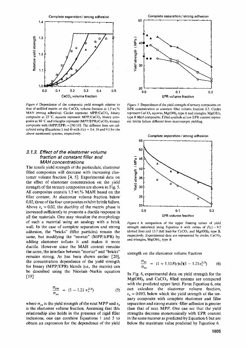
Figure 4 Dependence of the composite yield strength relative to that of unfilled matrix on the CaCO 3 volume fraction at 1.5 wt.% MAH (strong adhesion). Circles represent MPP/CaCOa binary composite at 23 ~ squares represent MPP/CaCO3 binary com- posite at 80 ~ and triangles represent (MPP/EPR)/CaCO3 ternary composite with (MPP/EPR) = 1-60/10]. The different lines are cal- culated using (Equations 1 and 6) with F(c) = 5.4, 18 and 9.5 for the above mentioned systems, respectively.
3. 1.3. Effect of the elastomer volume fraction at constant filler and MAH concentrations
The tensile yield strength of the particulate, elastomer filled composites will decrease with increasing elas- tomer volume fraction [4, 5]. Experimental data on the effect of elastomer concentration on the yield strength of the ternary composites are shown in Fig. 5. All composites contain 1.5 wt.% MAH based on the filler content. At elastomer volume fraction below 0.02; three of the four composites exhibit brittle failure. Above v~ -- 0.02, the ductility of the matrix phase is increased sufficiently to promote a ductile response in all the materials. One may visualize the morphology of such a material using an analogy with a brick wall. In the case of complete separation and strong adhesion, the "bricks" (filler particles) remain the same, but modifying the "mortar" (MPP/EPR) by adding elastomer softens it and makes it more ductile. However since the MAH content remains the same, the interface between "mortar" and "bricks" remains strong, As has been shown earlier [20], the concentration dependence of the yield strength for binary (MPP/EPR) blends (i.e., the matrix) can be described using the Nicolais-Narkis equation [19]
Crym = (1 - 1.21 v~/3) (5) O'y o
where Cryo is the yield strength of the neat M P P and v= is the elastomer volume fraction. Assuming that this relationship also holds in the presence of rigid filler inclusions, one can combine Equations 1 and 5 to obtain an expression for the dependence of the yield
50
A
40
f-
c-
-- 30
Complete separation / strong adhesion m i
2 0 = I i
0.0 0.1 0.2 EPR volume fraction
Figure 5 Dependence of the yield strength of ternary composites on EPR concentration at constant filler volume fraction 0.3. Circles represent CaCO3 squares, Mg(OH)2 type A and triangles, Mg(OH)2 type B filled composites. Filled symbols at low EPR content repres- ent brittle failure different from macroscopic yielding.
55
50
~. 45
40
e-
35 t~
"~ 30
25
20
0.0
Complete separation / strong adhesion i
-.-... ,
%~176176
0 "%*.~
= I =
0.1 0.2 EPR volume fraction
Figure 6 A comparison of the upper limiting values of yield strength calculated using Equation 6 with values of F(c)= 9.5 (dotted line) and 13.7 (full line) for CaCOa and Mg(OH)2 type B, respectively. Experimental data are represented by circles, CaCOa and triangles, Mg(OH)~ type B.
strength on the elastomer volume fraction
~r___2 = (1 + 1.33F(c)v~)(1 - 1.21v 2/3) (6) ~ y o
In Fig. 6, experimental data on yield strength for the Mg(OH)2 and CaCO3 filled systems are compared with the predicted upper limit. From Equation 6, one can calculate the elastomer volume fraction, ve --- 0.093, below which the yield strength of the ter- nary composite with complete elastomer and filler separation and strong matrix-filler adhesion is greater than that of neat MPP. One can see that the yield strengths decrease monotonically with EPR content in the same manner as predicted by Equation 6 but are below the maximum value predicted by Equation 6.
1605
28
26.
24' 0 -
~. 22 �84
t -
20
(D
% 18
16
Encapsulation process
/
S . . . _ _ . . . - o -
1 4 | i i
o 1 2 MAH content in MEPR ( wt % )
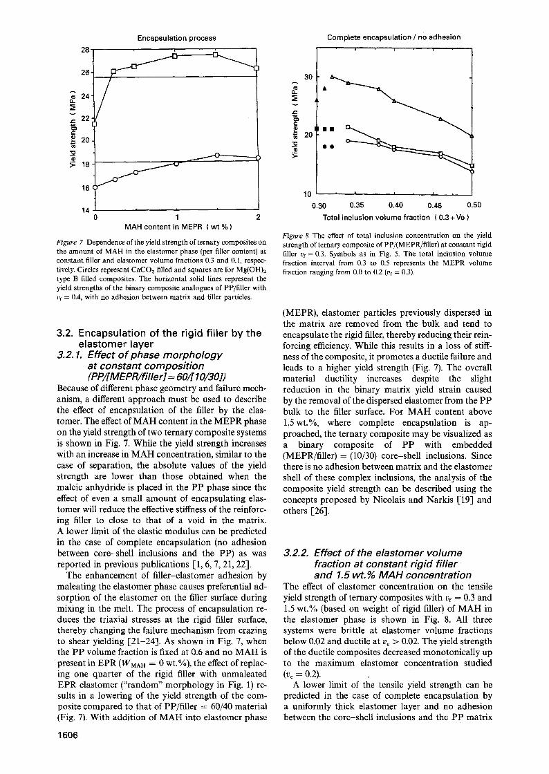
Figure 7 Dependence of the yield strength of ternary composites on the amount of MAH in the elastomer phase (per filler content) at constant filler and elastomer volume fractions 0.3 and 0.1, respec- tively. Circles represent CaCO3 filled and squares are for Mg(OH)z type B filled composites. The horizontal solid lines represent the yield strengths of the binary composite analogues of PP/filler with vf = 0.4, with no adhesion between matrix and filler particles.
3.2. E n c a p s u l a t i o n o f t he r ig id f i l l e r by t h e e l a s t o m e r l a y e r
3.2. 1. Effect of phase morphology at constant composition (PP/[MEPR/filler] = 60/[ 10/30])
Because of different phase geometry and failure mech- anism, a different approach must be used to describe the effect of encapsulation of the filler by the elas- tomer. The effect of MAH content in the MEPR phase on the yield strength of two ternary composite systems is shown in Fig. 7. While the yield strength increases with an increase in MAH concentration, similar to the case of separation, the absolute values of the yield strength are lower than those obtained when the maleic anhydride is placed in the PP phase since the effect of even a small amount of encapsulating elas- tomer will reduce the effective stiffness of the reinforc- ing filler to close to that of a void in the matrix. A lower limit of the elastic modulus can be predicted in the case of complete encapsulation (no adhesion between core-shell inclusions and the PP) as was reported in previous publications [1, 6, 7, 21, 22].
The enhancement of filler-elastomer adhesion by maleating the elastomer phase causes preferential ad- sorption of the elastomer on the filler surface during mixing in the melt. The process of encapsulation re- duces the triaxial stresses at the rigid filler surface, thereby changing the failure mechanism from crazing to shear yielding [21-24]. As shown in Fig. 7, when the P P volume fraction is fixed at 0.6 and no MAH is present in EPR ( W M A H = 0 wt.%), the effect of replac- ing one quarter of the rigid filler with unmaleated EPR elastomer ("random" morphology in Fig. 1) re- suits in a lowering of the yield strength of the com- posite compared to that of PP/filler = 60/40 material (Fig. 7). With addition of MAH into elastomer phase
1606
Complete encapsulation / no adhesion , i i
30
'~ 20
10 ' ' ' , ' ,
0.30 0.35 0.40 0.45 0.50
Total inclusion volume fraction ( 0 . 3+Ve )
Figure 8 The effect of total inclusion concentration on the yield strength of ternary composite of PP/(MEPR/filler) at constant rigid filler vf = 0.3. Symbols as in Fig. 5. The total inclusion volume fraction interval from 0.3 to 0.5 represents the MEPR volume fraction ranging from 0.0 to 0.2 (vf = 0.3).
(MEPR), elastomer particles previously dispersed in the matrix are removed from the bulk and tend to encapsulate the rigid filler, thereby reducing their rein- forcing efficiency. While this results in a loss of stiff- ness of the composite, it promotes a ductile failure and leads to a higher yield strength (Fig. 7). The overall material ductility increases despite the slight reduction in the binary matrix yield strain caused by the removal of the dispersed elastomer from the PP bulk to the filler surface. For MAH content above 1.5wt.%, where complete encapsulation is ap- proached, the ternary composite may be visualized as a binary composite of PP with embedded (MEPR/filler) = (10/30) core-shell inclusions. Since there is no adhesion between matrix and the elastomer shell of these complex inclusions, the analysis of the composite yield strength can be described using the concepts proposed by Nicolais and Narkis [19] and others [26].
3.2.2. Effect of the elastomer volume fraction at constant rigid filler and 1.5 wt.% MAH concentration
The effect of elastomer concentration on the tensile yield strength of ternary composites with vf = 0.3 and 1.5 wt.% (based on weight of rigid filler) of MAH in the elastomer phase is shown in Fig. 8. All three systems were brittle at elastomer volume fractions below 0.02 and ductile at ve > 0.02. The yield strength of the ductile composites decreased monotonically up to the maximum elastomer concentration studied (vo = 0.2).
A lower limit of the tensile yield strength can be predicted in the case of complete encapsulation by a uniformly thick elastomer layer and no adhesion between the core-shell inclusions and the PP matrix
1.2
1.0
c 0.8 .=
0.6
0.4 n - .
0.2
0.0
0.0
Complete encapsulation / no adhession
as-recieved CaC03
quation 7a ~
i | , |
0.1 0.2 0.3 0.4 Total inclusion volume fraction
0.5
e -
t -
r
n~
1.0
0.8
0.6
0.4
0.2 0.0
Complete encapsulation / no adhesion
, I i I v I i I i
0.1 0.2 0.3 0.4 0.5 Total filler volume fraction
1.0r
0.8 e -
e -
0.6
'~. CD
.> 0.4
n -
0.2
Complete encapsulation / no adhesion = �9 = �9
Equation 7b
0 . 0 , I , I , I , 1 =
0.0 0.1 0.2 0.3 0.4 0.5 Total filler volume fraction
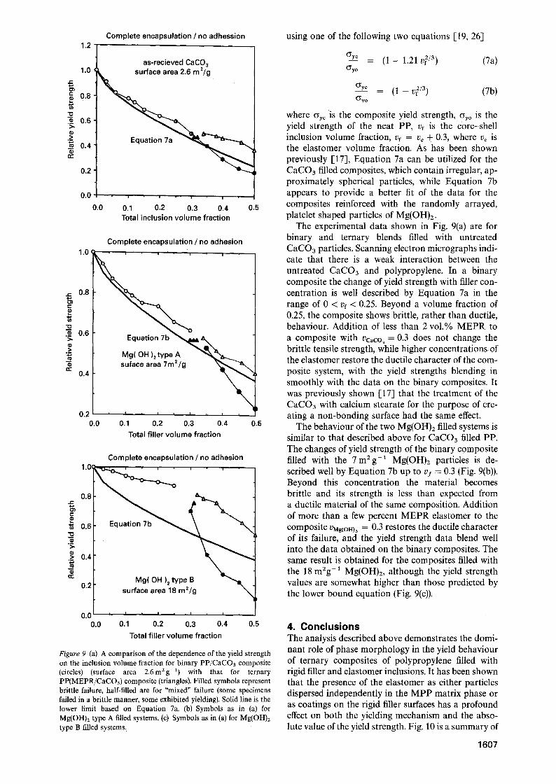
Figure 9 (a) A comparison of the dependence of the yield strength on the inclusion volume fraction for binary PP/CaCO3 composite (circles) (surface area 2.6m 2g-x) with that for ternary PP(MEPR/CaCO3) composite (triangles). Filled symbols represent brittle failure, half-filled are for "mixed" failure (some specimens failed in a brittle manner, some exhibited yielding). Solid line is the lower limit based on Equation 7a. (b) Symbols as in (a) for Mg(OHh type A filled systems. (c) Symbols as in (a) for Mg(OH)2 type B filled systems.
using one of the following two equations [19, 26]
O'y c - (1 - 1.21 v 2/3) (7a) O'y o
Cyy~ = ( 1 - v 2/3) (7b) (5"y o
where Cry c is the composite yield strength, Cry~ is the yield strength of the neat PP, vf is the c0re-shell inclusion volume fraction, vf = v, + 0.3, where ve is the elastomer volume fraction. As has been shown previously [17], Equation 7a can be utilized for the CaCO3 filled composites, which contain irregular, ap- proximately spherical particles, while Equation 7b appears to provide a better fit of the data for the composites reinforced with the randomly arrayed, platelet shaped particles of Mg(OH)2.
The experimental data shown in Fig. 9(a) are for binary and ternary blends filled with untreated CaCO3 particles. Scanning electron micrographs indi- cate that there is a weak interaction between the untreated CaCO3 and polypropylene. In a binary composite the change of yield strength with filler con- centration is well described by Equation 7a in the range of 0 < vf < 0.25. Beyond a volume fraction of 0.25, the composite shows brittle, rather than ductile, behaviour. Addition of less than 2 vol.% MEPR to a composite with VCaCO a = 0.3 does not change the brittle tensile strength, while higher concentrations, of the elastomer restore the ductile character of the com- posite system, with the yield strengths blending in smoothly with the data on the binary composites. It was previously shown [17] that the treatment of the CaCO3 with calcium stearate for the purpose of cre- ating a non-bonding surface had the same effect.
The behaviour of the two Mg(OH)2 filled systems is similar to that described above for CaCO3 filled PP. The changes of yield strength of the binary composite filled with the 7m2g -1 Mg(OH)2 particles is de- scribed well by Equation 7b up to v / = 0.3 (Fig. 9(b)). Beyond this concentration the material becomes brittle and its strength is less than expected from a ductile material of the same composition. Addition of more than a few percent MEPR elastomer to the composite UMg(OH) z = 0.3 restores the ductile character of its failure, and the yield strength data blend well into the data obtained on the binary composites. The same result is obtained for the composites filled with the 18 m2g -1 Mg(OH)2, although the yield strength values are somewhat higher than those predicted by the lower bound equation (Fig. 9(c)).
4. C o n c l u s i o n s The analysis described above demonstrates the domi- nant role of phase morphology in the yield behaviour of ternary composites of polypropylene filled with rigid filler and elastomer inclusions. It has been shown that the presence of the elastomer as either particles dispersed independently in the MPP matrix phase or as coatings on the rigid filler surfaces has a profound effect on both the yielding mechanism and the abso- lute value of the yield strength. Fig. 10 is a summary of
1 6 0 7
Limits of the yield s t reng th
1"4 i l .2
~- . & ~ Upper limit [] ~ . e q u a t m n 6
Q 1.0
0.8 "~.
"~ 0.6
0.4
0.2
0.0
�9 i-i []
�9 []
Lower limit equation 7b
0.1 0.2
Elastomer volume fraction
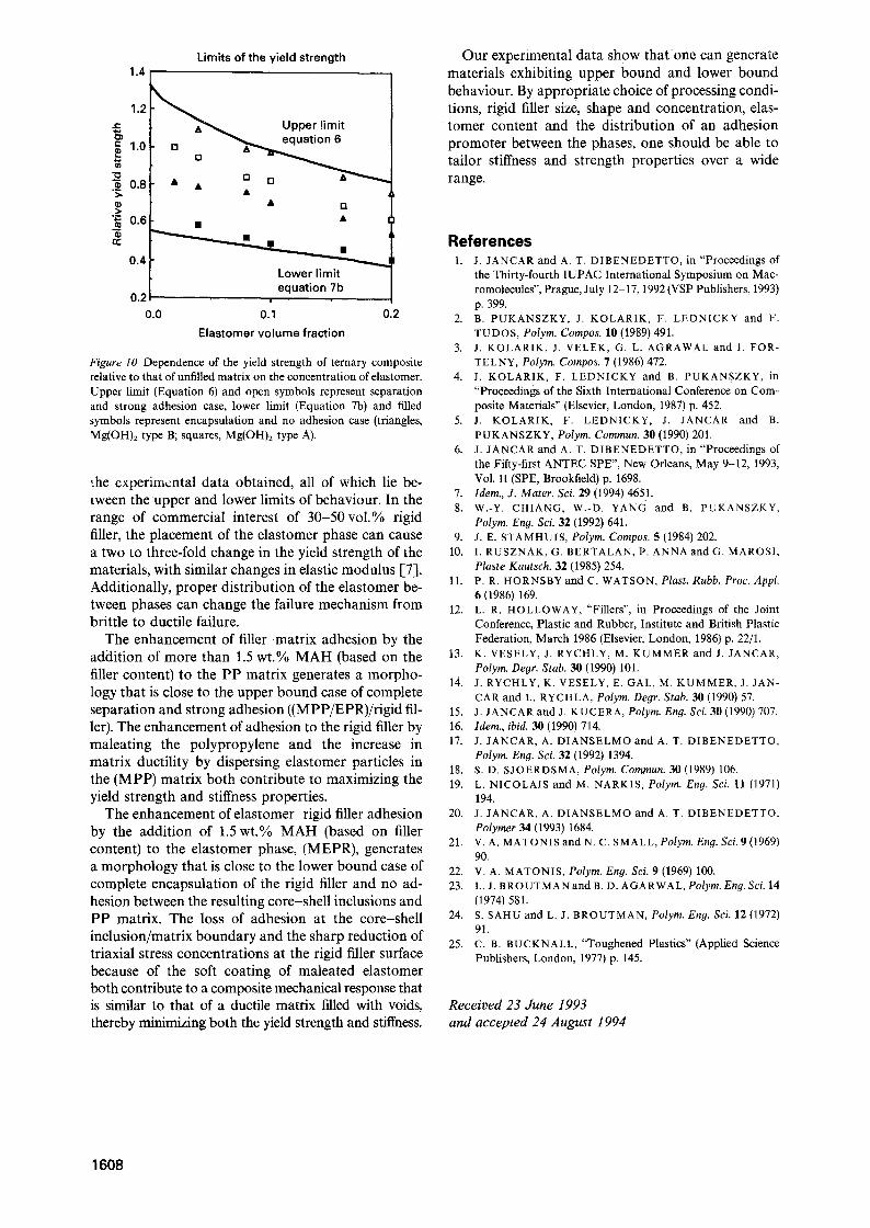
Figure 10 Dependence of the yield strength of ternary composite relative to that of unfilled matrix on the concentration of elastorner. Upper limit (Equation 6) and open symbols represent separation and strong adhesion case, lower limit (Equation 7b) and filled symbols represent encapsulation and no adhesion case (triangles, Mg(OH)2 type B; squares, Mg(OH)2 type A).
the experimental data obtained, all of which lie be- tween the upper and lower limits of behaviour. In the range of commercial interest of 30-50 vol.% rigid filler, the placement of the elastomer phase can cause a two to three-fold change in the yield strength of the materials, with similar changes in elastic modulus [7]. Additionally, proper distribution of the elastomer be- tween phases can change the failure mechanism from brittle to ductile failure.
The enhancement of filler-matrix adhesion by the addition of more than 1.5 wt.% MAH (based on the filler content) to the PP matrix generates a morpho- logy that is close to the upper bound case of complete separation and strong adhesion ((MPP/EPR)/rigid fil- ler). The enhancement of adhesion to the rigid filler by maleating the polypropylene and the increase in matrix ductility by dispersing elastomer particles in the (MPP) matrix both contribute to maximizing the yield strength and stiffness properties.
The enhancement of elastomer-rigid filler adhesion by the addition of 1.5 wt.% MAH (based on filler content) to the elastomer phase, (MEPR), generates a morphology that is close to the lower bound case of complete encapsulation of the rigid filler and no ad- hesion between the resulting core-shell inclusions and PP matrix. The loss of adhesion at the core-shell inclusion/matrix boundary and the sharp reduction of triaxial stress concentrations at the rigid filler surface because of the soft coating of maleated elastomer both contribute to a composite mechanical response that is similar to that of a ductile matrix filled with voids, thereby minimizing both the yield strength and stiffness.
Our experimental data show that one can generate materials exhibiting upper bound and lower bound behaviour. By appropriate choice of processing condi- tions, rigid filler size, shape and concentration, elas- tomer content and the distribution of an adhesion promoter between the phases, one should be able to tailor stiffness and strength properties over a wide range.
References 1. J. JANCAR and A. T. DIBENEDETTO, in "Proceedings of
the Thirty-fourth IUPAC International Symposium on Mac- romolecules", Prague, July 12-17, 1992 (VSP Publishers, 1993) p. 399.
2. B. PUKANSZKY, J. KOLARIK, F. LEDNICKY and F. TUDOS, Polym. Compos. 111 (1989) 491.
3. J. KOLARIK, J. VELEK, G. L. AGRAWAL and I. FOR- TELNY, Polym. Compos. 7 (1986) 472.
4. J. KOLARIK, F. LEDNICKY and B. PUKANSZKY, in "Proceedings of the Sixth International Conference on Com- posite Materials" (Elsevier, London, 1987) p. 452.
5. J. KOLARIK, F. LEDNICKY, J. JANCAR and B. PUKANSZKY, Polym. Commun. 311 (1990) 201.
6. J. JANCAR and A. T. DIBENEDETTO, in "Proceedings of the Fifty-first ANTEC SPE", New Orleans, May 9-12, 1993, Vol. II (SPE, Brookfield) p. 1698.
7. ldem., J. Mater. Sci. 29 (1994) 4651. 8. W.-Y. CHIANG, W.-D. YANG and B. PUKANSZKY,
Polym. Eng. Sci. 32 (1992) 641. 9. J .E. STAMHUIS, Polym. Compos. 5 (1984) 202.
10. I. RUSZNAK, G. BERTALAN, P. ANNA and G, MAROSI, Plaste Kautsch. 32 (1985) 254.
11. P. R, HORNSBY and C. WATSON, Plast. Rubb. Proc. Appl. 6 (1986) 169.
12. L. R. HOLLOWAY, "Fillers", in Proceedings of the Joint Conference, Plastic and Rubber, Institute and British Plastic Federation, March 1986 (Elsevier, London, 1986) p. 22/1.
13. K. VESELY, J. RYCHLY, M. KUMMER and J. JANCAR, Polym. Deor. Stab. 311 (1990) 101.
14. J. RYCHLY, K. VESELY, E. GAL, M. KUMMER, J. JAN- CAR and L. RYCHLA, Polym. De9 r. Stab. 311 (1990) 57.
15. J. JANCAR and J. KUCERA, Polym. En9. Sci. 30 (1990) 707. 16. Idem., ibid. 30 (1990) 714. 17. J. JANCAR, A. DIANSELMO and A. T. DIBENEDETTO,
Polym. Eng. Sci. 32 (1992) 1394. 18. S.D. SJOERDSMA, Polym. Commun. 311 (1989) 106. 19. L. NICOLAIS and M. NARKIS, Polym. Eng. Sci. 11 (1971)
194. 20. J. JANCAR, A. DIANSELMO and A. T. DIBENEDETTO,
Polymer 34 (1993) 1684. 21. V.A. MATONIS and N. C. SMALL, Polym. Eng. Sci. 9 (1969)
90. 22. v .A. MATONIS, Polym. Eng. Sci. 9 (1969) 100. 23. L.J. BROUTMAN and B. D. AGARWAL, Polym. Eng. Sci. 14
(1974) 581. 24. S. SAHU and L. J. BROUTMAN, Polym. Eng. Sci. 12 (1972)
91. 25. C. B. BUCKNALL, "Toughened Plastics" (Applied Science
Publishers, London, 1977) p. 145.
Received 23 June 1993 and accepted 24 August 1994
1608


