Embed Size (px)
Citation preview
Effect of Multiple-Pass Friction Stir Processing Overlappingon Microstructure and Mechanical Properties of As-CastNiAl Bronze
D.R. NI, P. XUE, and Z.Y. MA
As-cast Cu-9Al-4.5Ni-4Fe NiAl bronze alloy (NAB) was subjected to multiple-pass friction stirprocessing (FSP) with a 50 pct overlap. After FSP, the coarse microstructure of the base metal(BM) was transformed to defect-free material with fine microstructure. While the torchlikepatterns in the stir zone (SZ) and the uplifted grains in the transitional zones (TZs) between twopasses were observed in the multiple-pass FSP region, no grain coarsening was found in theremnant zone of the previous SZ after subsequent FSP pass. The hardness value of the FSPmaterials was higher than that of the BM and was homogeneously distributed throughout theentire multiple-pass FSP region. The FSP materials showed greatly improved tensile propertiescompared to the BM, and the TZs showed similar tensile strength and ductility to the single-passFSP materials. The BM broke in a mixture mode of brittle cleavage and microvoid coalescencefracture, whereas the FSP and TZ samples failed in the latter fracture mode. The results showedthat the multiple-pass overlapping (MPO) FSP was feasible to modify the microstructure oflarge-sized plate of the NAB.
DOI: 10.1007/s11661-011-0628-9� The Minerals, Metals & Materials Society and ASM International 2011
I. INTRODUCTION
THE NiAl bronze alloy (NAB) is extensively used forpropulsion and seawater handling systems[1–6] due to thehigh strength, good fracture toughness, and excellenterosion-corrosion resistance.[1–4,7] The as-cast NAB ischaracterized by coarse Widmanstatten a phase, nickel-iron-aluminum j phases, and island martensite b¢ phase,and the transformation products and their precipitationsequence are complex.[8–13] Furthermore, cast defectssuch as the shrinkage porosity and pores is a commonproblem for the NAB castings due to the poor castingproperties. This microstructure is disadvantageous tothe mechanical and corrosion properties of components.For example, the ASTM B148 cast alloy is used to makethe ship propellers; however, the yield strength (YS) ofslowly cooled regions in large propeller blades istypically 25 pct lower than the tensile property require-ments for the keel block for this alloy (241 MPa).[14]
Therefore, in order to improve the service life of the castNAB components, it is necessary to refine the coarseas-cast structure and eliminate the porosity defects.
In the past decade, a multifunctional metal workingtechnique named friction stir processing (FSP) has beenrapidly developed based on the basic principles offriction stir welding (FSW), which was invented at TheWelding Institute (TWI, United Kingdom) in 1991.[15–17]
This technique was first used by Mishra et al. to produce
fine-grained aluminum alloys,[18,19] and then applied tomodify the heterogeneous microstructure,[20] producesurface composites,[21,22] and synthesize composites andintermetallic compounds.[23,24] An important function ofFSP is to provide localized modification and control ofmicrostructure in the near-surface region of castingswithout changing the shape of components, with the aimto repair defects and to refine and homogenize thecoarse microstructures. This provides a simple andpromising way to solve the problem of the NAB, asmentioned previously.Previous investigations showed that FSP could effec-
tively refine the coarse microstructure of the NAB, healthe porosity defect, and homogenize the microstructure,thereby increasing the hardness, tensile properties,fatigue strength, and corrosion resistance.[14,25–27]
Oh-ishi and co-workers[28–32] reported that the maincharacteristic of the stir zone (SZ) of the FSP NAB wasinhomogeneous microstructures in various subregions,including Widmanstatten structure, equiaxed fine grainstructure, and banded or lamellar structure. Similarresults were also reported by Mahoney et al.[25] andFuller et al.[33] More recently, our study further showedthat the inhomogeneous microstructure was parameterdependent, and both the hardness and tensile propertiesof the as-cast NAB were greatly increased by FSP.[34]
Furthermore, the FSP sample showed much lowercorrosion rate in the static immersion corrosion condi-tion in neutral salt solution and a tiny variation inelectrochemical corrosion resistance.[35]
In practice, using FSP to modify the microstructureor heal the defects of a large-sized cast componentsmeans that multiple-pass overlapping (MPO) FSP witha certain level of overlap between the successive passes
D.R. NI, Assistant Professor, P. XUE, Postgraduate, and Z.Y. MA,Professor, are with the Shenyang National Laboratory for MaterialsScience, Institute of Metal Research, Chinese Academy of Sciences,Shenyang 110016, P.R. China. Contact e-mail: [email protected]
Manuscript submitted September 3, 2010.Article published online February 9, 2011
METALLURGICAL AND MATERIALS TRANSACTIONS A VOLUME 42A, AUGUST 2011—2125
should be applied. The MPO FSP mode is quite differentfrom the single-pass mode, because the subsequent passgenerates the heat-affected zone (HAZ) and thermome-chanically affected zone in the SZ of the previous pass.In this case, it is important to understand the micro-structure evolution during the MPO FSP and itsinfluence on the mechanical properties.
The MPO FSP of the cast NAB was previouslyreported,[14,26,36] and the effect of raster patterns (linearand rectangular spiral raster patterns) on the mechanicalproperties of the FSP material was compared. However,details such as the microstructure and mechanicalproperties of the transitional zones (TZs) between twoFSP passes were not discussed. In our previous studies,we reported that a single pass of FSP on the cast NABcould produce densified fine-grained material with goodmechanical properties and corrosion resistance.[34,35] Inthis study, we conducted the MPO FSP of the cast NAB.The aim is to examine the microstructure evolution andmechanical properties of the microregions in the MPOFSP cast NAB.
II. EXPERIMENTAL
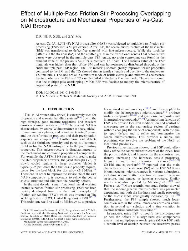
The 10-mm-thick commercial UNS C95800 NABalloy sand-cast plates with a composition of 9.18Al-4.49Ni-4.06Fe-1.03Mn-bal Cu (in wt pct) were used inthis study. The as-received NAB plates were machinedinto pieces with a dimension of 300 9 70 9 8 mm3. FSPwas performed under a tool rotation rate of 1200 rpmand a traverse speed of 50 mm min�1 with a tool tiltangle of 3 deg. A nickel-based superalloy tool with aconcave shoulder 24 mm in diameter and a threadedconical pin 8 mm in root diameter and 7 mm in lengthwere used. Both the tool and the processed workpiecewere subjected to blow over cooling during FSP. Alinear raster pattern with three passes was adopted(Figure 1). After each FSP pass, the pin was moved5 mm from the center of the former pass, which wasdetermined based on the size of the cross section of thesingle-pass FSP (Figure 2(a)). The FSP plate was cooledto room temperature prior to the next FSP pass toeliminate the effect of accumulative heating. All the FSPpasses were toward the same direction with the retreat-ing side (RS) being overlapped.
The microstructure of the base metal (BM) and theFSP samples were examined using optical microscopy(OM) after etching with solution of 5 g FeCl3+2 mLHCl+95 mL C2H5OH. The hardness profiles weremeasured along the midheight of the SZ on thetransverse cross section using a LECO-LM-247AT*
micro-Vickers hardness tester with a load of 5 kg for15 seconds. Three kinds of minitensile testing sampleswere prepared perpendicular to the FSP direction tomeasure the tensile properties of the FSP material. Dog-bone-shaped tensile specimens with a gage dimension of
5 9 1.5 9 0.85 mm3, 10 9 1.5 9 0.85 mm3, and15 9 1.5 9 0.85 mm3 were machined, perpendicular tothe FSP direction, with the gage center in the center ofthe single-pass FSP sample and the TZs, the two-passoverlapping FSP sample, and the three-pass overlappingFSP sample, respectively. Tensile specimens of the BMwere also prepared with a gage dimension of10 9 1.5 9 0.85 mm3 for comparison. Tensile tests wereconducted at a strain rate of 1910�3 s�1 at roomtemperature, using an Instron** 5848 tensile tester. The
property data for each condition were obtained byaveraging four test results. The fracture surfaces wereexamined on a scanning electron microscope (SEM,Quanta� 600).
III. RESULTS
A. Optical Microstructure
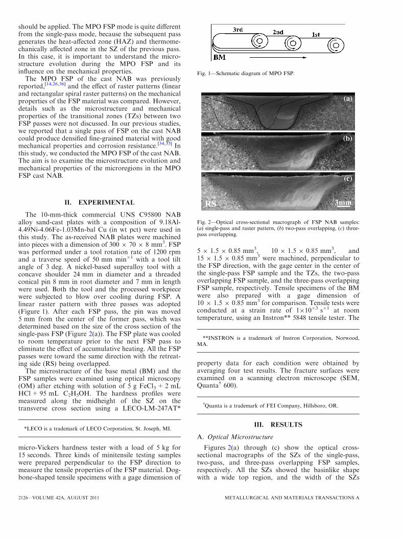
Figures 2(a) through (c) show the optical cross-sectional macrographs of the SZs of the single-pass,two-pass, and three-pass overlapping FSP samples,respectively. All the SZs showed the basinlike shapewith a wide top region, and the width of the SZs
Fig. 1—Schematic diagram of MPO FSP.
Fig. 2—Optical cross-sectional macrograph of FSP NAB samples:(a) single-pass and raster pattern, (b) two-pass overlapping, (c) three-pass overlapping.
*LECO is a trademark of LECO Corporation, St. Joseph, MI.
**INSTRON is a trademark of Instron Corporation, Norwood,MA.
�Quanta is a trademark of FEI Company, Hillsboro, OR.
2126—VOLUME 42A, AUGUST 2011 METALLURGICAL AND MATERIALS TRANSACTIONS A
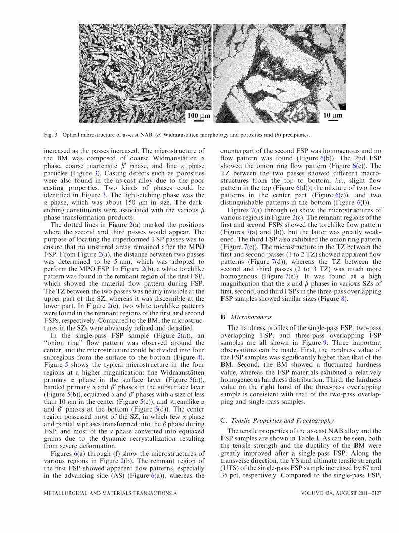
increased as the passes increased. The microstructure ofthe BM was composed of coarse Widmanstatten aphase, coarse martensite b¢ phase, and fine j phaseparticles (Figure 3). Casting defects such as porositieswere also found in the as-cast alloy due to the poorcasting properties. Two kinds of phases could beidentified in Figure 3. The light-etching phase was thea phase, which was about 150 lm in size. The dark-etching constituents were associated with the various bphase transformation products.
The dotted lines in Figure 2(a) marked the positionswhere the second and third passes would appear. Thepurpose of locating the unperformed FSP passes was toensure that no unstirred areas remained after the MPOFSP. From Figure 2(a), the distance between two passeswas determined to be 5 mm, which was adopted toperform the MPO FSP. In Figure 2(b), a white torchlikepattern was found in the remnant region of the first FSP,which showed the material flow pattern during FSP.The TZ between the two passes was nearly invisible at theupper part of the SZ, whereas it was discernible at thelower part. In Figure 2(c), two white torchlike patternswere found in the remnant regions of the first and secondFSPs, respectively. Compared to the BM, the microstruc-tures in the SZs were obviously refined and densified.
In the single-pass FSP sample (Figure 2(a)), an‘‘onion ring’’ flow pattern was observed around thecenter, and the microstructure could be divided into foursubregions from the surface to the bottom (Figure 4).Figure 5 shows the typical microstructure in the fourregions at a higher magnification: fine Widmanstattenprimary a phase in the surface layer (Figure 5(a)),banded primary a and b¢ phases in the subsurface layer(Figure 5(b)), equiaxed a and b¢ phases with a size of lessthan 10 lm in the center (Figure 5(c)), and streamlike aand b¢ phases at the bottom (Figure 5(d)). The centerregion possessed most of the SZ, in which few a phaseand partial j phases transformed into the b phase duringFSP, and most of the a phase converted into equiaxedgrains due to the dynamic recrystallization resultingfrom severe deformation.
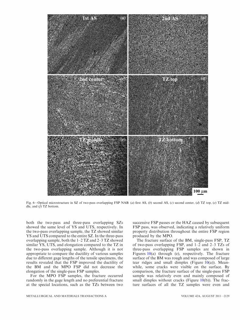
Figures 6(a) through (f) show the microstructures ofvarious regions in Figure 2(b). The remnant region ofthe first FSP showed apparent flow patterns, especiallyin the advancing side (AS) (Figure 6(a)), whereas the
counterpart of the second FSP was homogenous and noflow pattern was found (Figure 6(b)). The 2nd FSPshowed the onion ring flow pattern (Figure 6(c)). TheTZ between the two passes showed different macro-structures from the top to bottom, i.e., slight flowpattern in the top (Figure 6(d)), the mixture of two flowpatterns in the center part (Figure 6(e)), and twodistinguishable patterns in the bottom (Figure 6(f)).Figures 7(a) through (e) show the microstructures of
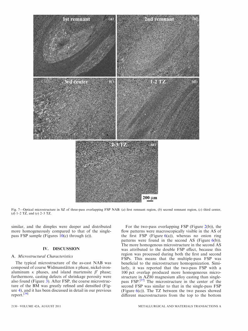
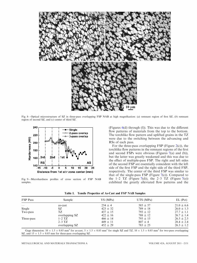
various regions in Figure 2(c). The remnant regions of thefirst and second FSPs showed the torchlike flow pattern(Figures 7(a) and (b)), but the latter was greatly weak-ened. The third FSP also exhibited the onion ring pattern(Figure 7(c)). The microstructure in the TZ between thefirst and second passes (1 to 2 TZ) showed apparent flowpatterns (Figure 7(d)), whereas the TZ between thesecond and third passes (2 to 3 TZ) was much morehomogenous (Figure 7(e)). It was found at a highmagnification that the a and b phases in various SZs offirst, second, and third FSPs in the three-pass overlappingFSP samples showed similar sizes (Figure 8).
B. Microhardness
The hardness profiles of the single-pass FSP, two-passoverlapping FSP, and three-pass overlapping FSPsamples are all shown in Figure 9. Three importantobservations can be made. First, the hardness value ofthe FSP samples was significantly higher than that of theBM. Second, the BM showed a fluctuated hardnessvalue, whereas the FSP materials exhibited a relativelyhomogeneous hardness distribution. Third, the hardnessvalue on the right hand of the three-pass overlappingsample is consistent with that of the two-pass overlap-ping and single-pass samples.
C. Tensile Properties and Fractography
The tensile properties of the as-cast NAB alloy and theFSP samples are shown in Table I. As can be seen, boththe tensile strength and the ductility of the BM weregreatly improved after a single-pass FSP. Along thetransverse direction, the YS and ultimate tensile strength(UTS) of the single-pass FSP sample increased by 67 and35 pct, respectively. Compared to the single-pass FSP,
Fig. 3—Optical microstructure of as-cast NAB: (a) Widmanstatten morphology and porosities and (b) precipitates.
METALLURGICAL AND MATERIALS TRANSACTIONS A VOLUME 42A, AUGUST 2011—2127
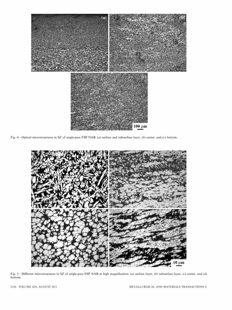
Fig. 4—Optical microstructures in SZ of single-pass FSP NAB: (a) surface and subsurface layer, (b) center, and (c) bottom.
Fig. 5—Different microstructures in SZ of single-pass FSP NAB at high magnification: (a) surface layer, (b) subsurface layer, (c) center, and (d)bottom.
2128—VOLUME 42A, AUGUST 2011 METALLURGICAL AND MATERIALS TRANSACTIONS A
both the two-pass and three-pass overlapping SZsshowed the same level of YS and UTS, respectively. Inthe two-pass overlapping sample, the TZ showed similarYS and UTS compared to the entire SZ. In the three-passoverlapping sample, both the 1–2 TZ and 2–3 TZ showedsimilar YS, UTS, and elongation compared to the TZ inthe two-pass overlapping sample. Although it is notappropriate to compare the ductility of various samplesdue to different gage lengths of the tensile specimens, theresults revealed that the FSP improved the ductility ofthe BM and the MPO FSP did not decrease theelongation of the single-pass FSP samples.
For the MPO FSP samples, the fracture occurredrandomly in the gage length and no preferential fractureat the special locations, such as the TZs between two
successive FSP passes or the HAZ caused by subsequentFSP pass, was observed, indicating a relatively uniformproperty distribution throughout the entire FSP regionproduced by the MPO.The fracture surface of the BM, single-pass FSP, TZ
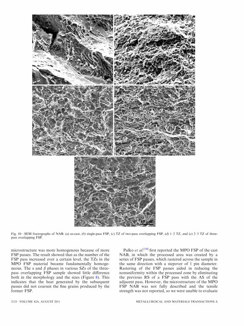
of two-pass overlapping FSP, and 1–2 and 2–3 TZs ofthree-pass overlapping FSP samples are shown inFigures 10(a) through (e), respectively. The fracturesurface of the BM was rough and was composed of largetear ridges and small dimples (Figure 10(a)). Mean-while, some cracks were visible on the surface. Bycomparison, the fracture surface of the single-pass FSPsample was relatively even and mainly composed ofsmall dimples without cracks (Figure 10(b)). The frac-ture surfaces of all the TZ samples were even and
Fig. 6—Optical microstructure in SZ of two-pass overlapping FSP NAB: (a) first AS, (b) second AS, (c) second center, (d) TZ top, (e) TZ mid-dle, and (f) TZ bottom.
METALLURGICAL AND MATERIALS TRANSACTIONS A VOLUME 42A, AUGUST 2011—2129
similar, and the dimples were deeper and distributedmore homogeneously compared to that of the single-pass FSP sample (Figures 10(c) through (e)).
IV. DISCUSSION
A. Microstructural Characteristics
The typical microstructure of the as-cast NAB wascomposed of coarse Widmanstatten a phase, nickel-iron-aluminum j phases, and island martensite b¢ phase;furthermore, casting defects of shrinkage porosity werealso found (Figure 3). After FSP, the coarse microstruc-ture of the BM was greatly refined and densified (Fig-ure 4), and it has been discussed in detail in our previousreport.[34]
For the two-pass overlapping FSP (Figure 2(b)), theflow patterns were macroscopically visible in the AS ofthe first FSP (Figure 6(a)), whereas no onion ringpatterns were found in the second AS (Figure 6(b)).The more homogenous microstructure in the second ASwas attributed to the double FSP effect, because thisregion was processed during both the first and secondFSPs. This means that the multiple-pass FSP wasbeneficial to the microstructure homogenization. Simi-larly, it was reported that the two-pass FSP with a100 pct overlap produced more homogeneous micro-structure in AZ80 magnesium alloy casting than single-pass FSP.[37] The microstructure in the center of thesecond FSP was similar to that in the single-pass FSP(Figure 6(c)). The TZ between the two passes showeddifferent macrostructures from the top to the bottom
Fig. 7—Optical microstructure in SZ of three-pass overlapping FSP NAB: (a) first remnant region, (b) second remnant region, (c) third center,(d) 1–2 TZ, and (e) 2–3 TZ.
2130—VOLUME 42A, AUGUST 2011 METALLURGICAL AND MATERIALS TRANSACTIONS A
(Figures 6(d) through (f)). This was due to the differentflow patterns of materials from the top to the bottom.The torchlike flow pattern and uplifted grains in the TZwere due to the switching between the advancing andRSs of each pass.For the three-pass overlapping FSP (Figure 2(c)), the
torchlike flow patterns in the remnant regions of the firstand second FSPs were obvious (Figures 7(a) and (b)),but the latter was greatly weakened and this was due tothe effect of multiple-pass FSP. The right and left sidesof the second FSP are essentially coincident with the leftside of the first FSP and the right side of the third FSP,respectively. The center of the third FSP was similar tothat of the single-pass FSP (Figure 7(c)). Compared tothe 1–2 TZ (Figure 7(d)), the 2–3 TZ (Figure 7(e))exhibited the greatly alleviated flow patterns and the
Fig. 8—Optical microstructure of SZ in three-pass overlapping FSP NAB at high magnification: (a) remnant region of first SZ, (b) remnantregion of second SZ, and (c) center of third SZ.
Fig. 9—Microhardness profiles of cross section of FSP NABsamples.
Table I. Tensile Properties of As-Cast and FSP NAB Samples
FSP Pass Sample YS (MPa) UTS (MPa) EL (Pct)
— as-cast 254 ± 4 585 ± 57 21.0 ± 6.6Single SZ 423 ± 32 789 ± 18 26.0 ± 1.3Two-pass TZ 437 ± 15 793 ± 12 27.7 ± 1.1
overlapping SZ 422 ± 16 788 ± 12 26.7 ± 1.4Three-pass 1–2 TZ 466 ± 14 793 ± 15 26.5 ± 2.5
2–3 TZ 449 ± 11 807 ± 4 28.4 ± 2.4overlapping SZ 452 ± 29 783 ± 25 26.3 ± 1.2
Gage dimension: 10 9 1.5 9 0.85 mm3 for as-cast, 5 9 1.5 9 0.85 mm3 for single SZ and TZ, 10 9 1.5 9 0.85 mm3 for two-pass overlappingSZ, and 15 9 1.5 9 0.85 mm for three-pass overlapping SZ.
METALLURGICAL AND MATERIALS TRANSACTIONS A VOLUME 42A, AUGUST 2011—2131
microstructure was more homogenous because of moreFSP passes. The result showed that as the number of theFSP pass increased over a certain level, the TZs in theMPO FSP material became fundamentally homoge-neous. The a and b phases in various SZs of the three-pass overlapping FSP sample showed little differenceboth in the morphology and the sizes (Figure 8). Thisindicates that the heat generated by the subsequentpasses did not coarsen the fine grains produced by theformer FSP.
Palko et al.[14] first reported the MPO FSP of the castNAB, in which the processed area was created by aseries of FSP passes, which rastered across the sample inthe same direction with a stepover of 1 pin diameter.Rastering of the FSP passes aided in reducing thenonuniformity within the processed zone by eliminatingthe previous RS of a FSP pass with the AS of theadjacent pass. However, the microstructure of the MPOFSP NAB was not fully described and the tensilestrength was not reported, so we were unable to evaluate
Fig. 10—SEM fractographs of NAB: (a) as-cast, (b) single-pass FSP, (c) TZ of two-pass overlapping FSP, (d) 1–2 TZ, and (e) 2–3 TZ of three-pass overlapping FSP.
2132—VOLUME 42A, AUGUST 2011 METALLURGICAL AND MATERIALS TRANSACTIONS A
this MPO mode. Fuller et al.[26] and Mahoney et al.[36]
investigated a series of raster approaches for the MPOFSP of the cast NAB. Their results showed that, forlinear patterns, if the tool rotation direction was notchanged following the completion of each pass, the ASand RS microstructure zones were produced, and thisresulted in an inhomogeneous processed zone. This kindof structure was consistent with our result. For arectangular spiral out raster pattern with the AS on theinterior of the pattern, the microstructure was morehomogeneous, but the AS material was created duringeach pass resulting in a distinct vertical flow of materialbetween passes.[26,36] They considered that this AS orinterpass microstructure was softer than the adjacentprocessed material. However, for this rectangularpattern, changing the tool travel direction moved theAS microstructure to the raster boundary, thus a SZwith homogeneous and fine grain microstructure wasgenerated without the banded interpass microstructure,and they considered this kind of microstructure bene-ficial to the ductility.
B. Microhardness
The horizontal hardness profiles along the midheightof the SZ center of the single-pass, two-pass overlap-ping, and three-pass overlapping FSP samples indicatedthat FSP improved the hardness of the as-cast NAB(Figure 9). The increase of the hardness should beattributed to the microstructure refinement and theelimination of the casting defects in the BM. On the onehand, according to the Hall–Patch relationship, themicrostructure refinement of the coarse BM couldprovide higher hardness. On the other hand, the castingporosities in the BM were closed during FSP, and thiswas certainly beneficial to the increase and homogeni-zation of hardness. The hardness of the overlapping FSPsamples was in agreement with that of the single-passFSP sample. This result showed that no weakenedregion appeared in the MPO FSP materials, and thiswas consistent with the results of Palko et al.,[14] inwhich the microhardness across the rastered microstruc-ture showed a uniform distribution within the processedzone. Although nearly 50 pct of the SZ area wasoverlapped, the hardness value of the repeated FSPregion did not increase. This was in good agreementwith our previous study, in which the in-situ two-passFSP sample did not exhibit higher hardness value thanthe single-pass one.[34] The hardness values of thepresent MPO FSP samples are consistent with theprevious reports, in which the hardness values of about190 to 220 Hv and 190 to 215 Hv were recorded for9- and 20-mm-thick FSP NAB, respectively.[14] Thismeans that the MPO mode adopted here did notdecrease the hardness value of the FSP materials.
C. Tensile Properties and Fractography
Both the single-pass and the MPO FSP samplesexhibited significantly improved tensile strength andductility compared to the as-cast NAB (Table I). Theimprovement in the tensile properties of the FSP NAB
was ascribed to the refinement of the coarse microstruc-ture and the elimination of the casting defects, asdiscussed for the increase of the hardness. The strengthof the two-pass and three-pass overlapping samples wasat the same level as that of the single-pass FSP sample,and this indicates that increasing the number of over-lapping FSP passes hardly affects the tensile propertiesof the overlapping NAB. Both the 1–2 TZ and 2–3 TZ inthe three-pass overlapping sample showed similarstrength and elongation to the TZ in the two-passoverlapping sample, indicating that the tensile proper-ties of the TZ were stable and were not visibly affectedby the subsequent passes.Fuller et al.[26] reported that the YS and UTS of the
MPO FSP NAB were 504 to 522 MPa and 765 to805 MPa in a linear raster pattern and 460 to 507 MPaand 743 to 761 MPa in a rectangular raster pattern,respectively. The linear pattern showed a higher tensilestrength and a lower ductility compared to the rectan-gular pattern, and the lower ductility was attributed tothe inhomogeneous microstructure. Meanwhile, chang-ing the raster pattern from linear to rectangular spiralslightly lowered the overall fatigue resistance, but it didnot produce any significant change in fatigue datascatter. These results revealed that, although the linearraster pattern generated the torchlike structure in theSZ, it may provide better mechanical properties for theMPO FSP materials. Compared to their results, the YSvalues in the present study were lower, whereas the UTSvalues were similar.The tensile strengths of the present MPO FSP NAB
were better than those of the single-pass FSP NABreported by Palko et al.[14] in which the YS and UTSwere 400 to 420 MPa and 689 to 724 MPa, respectively,and those reported by Mahoney et al.[25] in which theYS and UTS are 433 and 741 MPa, respectively.Meanwhile, the tensile strengths were lower than ourpreviously reported results for the single-pass FSPNAB,[34] and this may be due to the BMs, which camefrom different batches. Because the tensile specimenswith different dimensions were used in this study, it isimpossible to compare the present elongation valueswith the previous ones (14 to 16 pct and 23 pct inReferences 14 and 25, respectively). However, thepresent results indicated that the MPO FSP materialshad a proper ductility.Santella et al.[38] reported the MPO FSP on as-cast
A356 and A319 alloys with five to six passes overlappingat intervals of about 4 mm. After FSP, the microstruc-tures were refined and homogenized, and the visibleporosity and dendritic microstructures were eliminated.The transverse samples covering the entire FSP regionproduced by the MPO FSP showed better UTS,ductility, and fatigue life compared to the BM, showingthat the MPO FSP is useful for engineering applicationsof these alloys. However, they did not provide an insightinto the correlation between the intrinsic tensile prop-erties and the localized microstructure. Ma et al.[39]
further investigated the effect of MPO, five pass with50 pct overlapping, on the microstructure and tensileproperties of cast A356 alloy. The overlapping FSP didnot exert a significant effect on the size and distribution
METALLURGICAL AND MATERIALS TRANSACTIONS A VOLUME 42A, AUGUST 2011—2133
of the Si particles. The strength and ductility of the TZsbetween two FSP passes were slightly lower than thoseof the SZs, and the previously processed zones showedlower strength compared to the subsequently processedzones due to overaging from the FSP thermal cycles.However, after T6 heat treatment, the tensile propertiesof the five-pass FSP A356 samples were similar acrossvarious passes and comparable to those of the single-pass FSP sample. Their results showed that the ther-momechanical history of the subsequent FSP passes didgenerate adverse effects on the MPO FSP materials.However, this phenomenon was not found in the presentstudy, and this should be attributed to the fact that theNAB was less sensitive to heat treatment compared tothe A356 alloy.
The fracture surface of the BM (Figure 10(a)) wasrough and covered with large tear ridges, small dimples,and cracks, indicating that the sample broke in themanner of brittle cleavage and ductile microvoid coa-lescence fracture mode. This is attributed to the presenceof the coarse hard and brittle martensite b¢ phase, thesegregated j-phase particles, and the casting porosities,which resulted in easy initiation and propagation ofcracks. Due to the effect of the microstructure refine-ment, homogenization, and densification, the single-passFSP sample exhibited a relatively even fracture surface,which was mainly composed of small dimples withouttear ridges and cracks, and it failed in the microvoidcoalescence fracture mode (Figure 10(b)). The presentresult was in agreement with that of Fuller et al.[33] Thisfracture surface further indicated that the FSP samplesshowed better tensile strength and elongation than theBM.
The effect of the grain refinement by FSP on thefracture behavior was also reported by Feng and Ma.[40]
Their results showed that the as-cast AZ91D magnesiumalloy exhibited a brittle fracture mode, and the coarseeutectic b-Mg17Al12 network at the grain boundarieswas prone to crack or debond from the magnesiummatrix, whereas the FSP sample exhibited a typicalductile dimple fracture, because FSP resulted in signif-icant breakup and dissolution of the coarse eutectic bphase and remarkable grain refinement.
Compared to that of the single-pass FSP sample, theTZ samples also broke in the microvoid coalescencefracture mode, and the dimples on the fracture surfaceswere deeper and distributed more homogeneously (Fig-ures 10(c) through (e)). This was due to the fact that theTZs received multiple passes of FSP, and their micro-structure was more homogeneous. All the TZs showedsimilar fracture surfaces, and this indicates that theMPO FSP did not affect the fracture behavior of theoverlapping samples, and this can be further proved bythe randomly distributed fracture positions.
V. CONCLUSIONS
1. MPO FSP greatly refined the microstructure of theas-cast NAB and generated a defect-free SZ. DuringFSP, the switching between AS and RS of eachpass generated the torchlike patterns in the SZ and
the uplifted grains in the TZs.2. The heat generated by the following passes did not
coarsen the fine grains of the former FSP. For thethree-pass overlapping NAB, the a and b phases inthe three SZs showed little difference both in themorphology and the size.
3. The FSP materials showed significantly higher hard-ness value and more homogeneous hardness distri-bution than the BM. The hardness value of theMPO FSP materials was similar to that of the sin-gle-pass FSP without weakened region.
4. The MPO FSP materials showed greatly improvedtensile properties compared to the BM. The YS,UTS, and elongation were about 422 MPa,788 MPa, and 26.7 pct, respectively, for the two-pass FSP sample, and about 452 MPa, 783 MPa,and 26.3 pct, respectively, for the three-pass FSPsample. The TZs showed similar strengths and elon-gation to the single-pass FSP material.
5. The FSP sample showed an even fracture surfacecomposed of small dimples, which failed in a micro-void coalescence fracture mode. Compared to theFSP sample, the TZ samples showed similar frac-ture surfaces with the dimples being deeper and dis-tributed more homogeneously.
ACKNOWLEDGMENTS
This work was supported by the National Outstand-ing Young Scientist Foundation under Grant No.50525103, the National Basic Research Program ofChina under Grant No. 2006CB605205, the NationalHigh-tech Research Program under Grant No.2006AA03Z111, and the Hundred Talents Program ofthe Chinese Academy of Sciences.
REFERENCES1. E.A. Culpan and G. Rose: Br. Corros. J., 1979, vol. 14, pp. 160–
66.2. R.J. Ferrara and T.E. Caton: Mater. Perform., 1982, vol. 21,
pp. 30–34.3. G.W. Lorimer, F. Hasan, J. Iqbal, and N. Ridley: Br. Corros. J.,
1986, vol. 21, pp. 244–48.4. C.H. Tang, F.T. Cheng, and H.C. Man: Mater. Sci. Eng. A, 2004,
vol. 373, pp. 195–203.5. G. Kear, B.D. Barker, K. Stokes, and F.C. Walsh: J. Appl.
Electrochem., 2004, vol. 34, pp. 1235–40.6. G. Kear, B.D. Barker, K. Stokes, and F.C. Walsh: J. Appl.
Electrochem., 2004, vol. 34, pp. 1241–48.7. A. Al-Hashem and W. Riad: Mater. Charact., 2002, vol. 48,
pp. 37–41.8. E.A. Culpan and G. Rose: J. Mater. Sci., 1978, vol. 13, pp. 1647–
57.9. M. Sahoo: Trans. AFS, 1982, vol. 90, pp. 913–26.10. A. Jahanafrooz, F. Hasan, G.W. Lorimer, and N. Ridley: Metall.
Trans. A, 1983, vol. 14A, pp. 1951–56.11. E.A. Feest and I.A. Cook: Met. Technol., 1983, vol. 10, pp. 121–
24.12. F. Hasan, J. Iqbal, and N. Ridley: Mater. Sci. Technol., 1985,
vol. 1, pp. 312–15.13. F. Hasan, A. Jahanafrooz, G.W. Lorimer, and N. Ridley: Metall.
Trans. A, 1982, vol. 13A, pp. 1337–45.14. W.A. Palko, R.S. Fielder, and P.F. Young: Mater. Sci. Forum,
2003, vols. 426–432, pp. 2909–14.
2134—VOLUME 42A, AUGUST 2011 METALLURGICAL AND MATERIALS TRANSACTIONS A
15. R.S. MishraandZ.Y.Ma:Mater.Sci.Eng.R, 2005, vol. 50, pp. 1–78.16. R. Nandan, T. DebRoy, and H.K.D.H. Bhadeshia: Progr. Mater.
Sci., 2008, vol. 53, pp. 980–1023.17. P.L. Threadgill, A.J. Leonard, H.R. Shercliff, and P.J. Withers:
Int. Mater. R., 2009, vol. 54, pp. 49–93.18. R.S. Mishra, M.W. Mahoney, S.X. McFadden, N.A. Mara, and
A.K. Mukherjee: Scripta Mater., 2000, vol. 42, pp. 163–68.19. R.S. Mishra and M.W. Mahoney: ICSAM-2000, 2001, vols. 357–
359, pp. 507–12.20. P.B. Berbon, W.H. Bingel, R.S. Mishra, C.C. Bampton, and M.W.
Mahoney: Scripta Mater., 2001, vol. 44, pp. 61–66.21. R.S. Mishra, Z.Y. Ma, and I. Charit: Mater. Sci. Eng. A, 2002,
vol. 341, pp. 307–10.22. A.S. Zarghani, S.F.K. Bozorg, and A.Z. Hanzaki:Mater. Sci. Eng.
A, 2009, vol. 500, pp. 84–91.23. C.J. Hsu, C.Y. Chang, P.W. Kao, N.J. Ho, and C.P. Chang: Acta
Mater., 2006, vol. 54, pp. 5241–49.24. C.H. Chuang, J.C. Huang, and P.J. Hsieh: Scripta Mater., 2005,
vol. 53, pp. 1455–60.25. M.W. Mahoney, W.H. Bingel, S.R. Sharma, and R.S. Mishra:
Mater. Sci. Forum, 2003, vols. 426–432, pp. 2843–48.26. C.B. Fuller, M.W. Mahoney, W.H. Bingel, M. Calabrese, and B.
London: Mater. Sci. Forum, 2007, vols. 539–543, pp. 3751–56.27. P.S. Prevey, D.J. Hornbach, and D.N. Jayaraman: Mater. Sci.
Forum, 2007, vols. 539–543, pp. 3807–13.
28. K. Oh-ishi and T.R. McNelley: Metall. Mater. Trans. A, 2004,vol. 35A, pp. 2951–61.
29. K. Oh-ishi, A.M. Cuevas, D.L. Swisher, and T.R. McNelley:Mater. Sci. Forum, 2003, vols. 426–432, pp. 2885–90.
30. K. Oh-ishi and T.R. McNelley: Metall. Mater. Trans. A, 2005,vol. 36A, pp. 1575–85.
31. K. Oh-ishi, A.P. Zhilyaev, and T.R. McNelley: Metall. Mater.Trans. A, 2006, vol. 37A, pp. 2239–51.
32. T.R. McNelley, K. Oh-ishi, and A.P. Zhilyaev: Mater. Sci. Forum,2007, vols. 539–543, pp. 3745–50.
33. M.D. Fuller, S. Swaminathan, A.P. Zhilyaev, and T.R. McNelley:Mater. Sci. Eng. A, 2007, vol. 463, pp. 128–37.
34. D.R. Ni, P. Xue, D. Wang, B.L. Xiao, and Z.Y. Ma: Mater. Sci.Eng. A, 2009, vol. 524, pp. 118–28.
35. D.R. Ni, B.L. Xiao, Z.Y. Ma, Y.X. Qiao, and Y.G. Zheng: Cor-ros. Sci., 2010, vol. 52, pp. 1610–17.
36. M.W. Mahoney, C. Fuller, W.H. Bingel, and M. Calabrese:Mater. Sci. Forum, 2007, vols. 539–543, pp. 3721–26.
37. A.H. Feng, B.L. Xiao, and Z.Y. Ma: Metall. Mater. Trans. A,2009, vol. 40A, pp. 2447–56.
38. M.L. Santella, T. Engstrom, D. Storjohann, and T.Y. Pan: ScriptaMater., 2005, vol. 53, pp. 201–06.
39. Z.Y. Ma, S.R. Sharma, and R.S. Mishra: Scripta Mater., 2006,vol. 54, pp. 1623–26.
40. A.H. Feng and Z.Y.Ma: ScriptaMater., 2007, vol. 56, pp. 397–400.
METALLURGICAL AND MATERIALS TRANSACTIONS A VOLUME 42A, AUGUST 2011—2135