Embed Size (px)
Citation preview

Effect of Pitch Difference between theBolt-Nut Connections upon the Anti-LooseningPerformance and Fatigue Life
著者 Noda Nao-Aki, Chen Xin, Sano Yoshikazu,Wahab Magd Abdel, Maruyama Hikaru, Fujisawa Ryota, Takase Yasushi
journal orpublication title
Materials & Design
volume 96page range 476-489year 2016-04-15URL http://hdl.handle.net/10228/00006711
doi: info:doi/10.1016/j.matdes.2016.01.128
1
Effect of Pitch Difference between the Bolt-Nut Connections upon the
Anti-Loosening Performance and Fatigue Life
Nao-Aki Nodaa*
, Xin Chena,b
, Yoshikazu Sanoa, Magd Abdel Wahab
b,
Hikaru Maruyamaa, Ryota Fujisawa
a, Yasushi Takase
a
aDepartment of Mechanical Engineering, Kyushu Institute of Technology,Kitakyushu 804-8550, Japan bDepartment of Mechanical Construction and Production, Faculty of Engineering and Architecture,
GhentUniversity, 9000 Ghent, Belgium
*Corresponding author: [email protected]
Abstract
In this paper, the effect of a slight pitch difference between a bolt and nut is studied. Firstly,
by varying the pitch difference, the prevailing torque required for the nut rotation, before the nut
touches the clamped body, is measured experimentally. Secondly, the tightening torque is
determined as a function of the axial force of the bolt after the nut touches the clamped body.
The results show that a large value of pitch difference may provide large prevailing torque that
causes an anti-loosening effect although a very large pitch difference may deteriorate the bolt
axial force under a certain tightening torque. Thirdly, a suitable pitch difference is determined
taking into account the anti-loosening and clamping abilities. Fourthly, fatigue experiments are
conducted using three different values of pitch difference for various stress amplitudes. It is
found that the fatigue life could be extended when a suitable pitch difference is considered
Furthermore, the chamfered corners at nut ends are considered, and it is found that the finite
element analysis with considering the chamfered nut threads has a good agreement with the
experimental observation. Finally, the most desirable pitch difference required for improving
both anti-loosening and fatigue life is proposed.
Keywords: Bolt-nut connection, Pitch difference, Anti-loosening performance, Fatigue life,
Finite element method
© 2016. This manuscript version is made available under the CC-BY-NC-ND 4.0 license http://creativecommons.org/licenses/by-nc-nd/4.0/
ACCEPTED MANUSCRIPT
2
1 Introduction
The bolt-nut connections are important joining elements and are widely used to
connect and disconnect members conveniently at a low cost. Reference [1] fully
reviewed the history as well as the evolution of the screw fasteners. To ensure that
structures are safety joined, good anti-loosening performance and high fatigue strength
are required. Most previous studies have been mainly focusing on anti-loosening
performance [2-7], and few studies have contributed to improvements in the fatigue
strength [8-17]. This is because a high stress concentration factor, e.g. Kt=3-5, appears
at the No.1 bolt thread and it is not easy to reduce it. Moreover, usually for special bolt-
nut connections the anti-loosening ability affects the fatigue strength and the cost
significantly. In other words, anti-loosening bolt-nut connections have not been
developed until now without a reduction in fatigue strength and a raising in the cost.
This paper, therefore, focuses on the effect of pitch difference in a connection on the
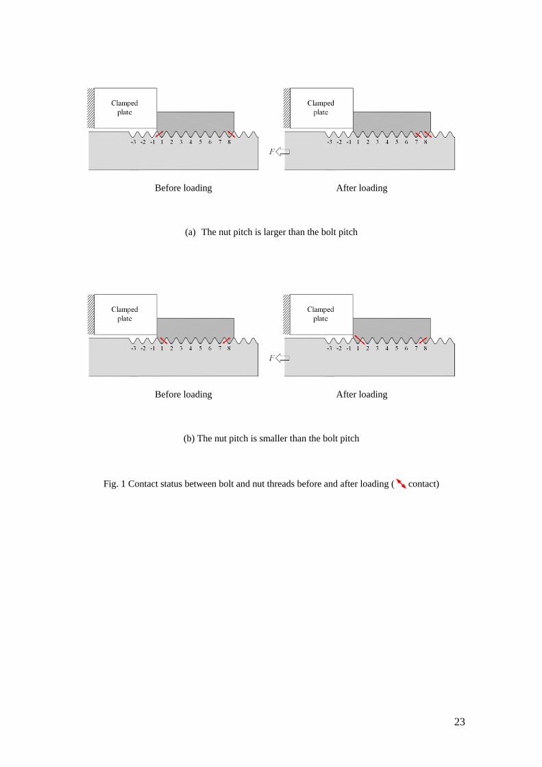
anti-loosing performance and fatigue life. As shown in Fig. 1, if the nut pitch is larger
than the bolt pitch, the thread No. 1 at the left-hand side is in contact before the loading
and becomes in no-contact status after the loading as shown in Fig. 1 (a). However, if
the nut pitch is smaller than the bolt pitch, the thread No.1 at the right-hand side is in
contact before the loading and remains in contact after loading, also the contact force
becomes larger after the loading as shown in Fig. 1 (b). Therefore, the largest stress
concentration at thread No.1 can be reduced only by a larger nut pitch.
The concept of differential pitch was first suggested by Stromeyer [18] in 1918. He
suggested that the load distribution in a threaded connection thread could be optimized
by varying the relative pitches. Then, the theoretical load distribution in bolt-nut has
been developed by Sopwith [19], who also used his formula to discuss the load
distribution improvement along the bolt threads by varing pitch. He found that a smaller
3
pitch in the bolt than in the nut would improve the load distribution. Sparling [20] found
that the fatigue strength of the bolt can be improved by increasing the clearance between
the first few engaged threads at the load bearing face of the nut by tapering the nut
thread, which produces an effective difference in pitch. This modification was
investigated by Kenny and Patterson [21, 22] by applying the frozen stress three-
dimensional photoelasticity. Maruyama [23] analyzed the influence of pitch error and
the loaded flank angle error of the bolt thread upon the stress at the root of the bolt
thread by copper-electroplating method with the finite element method. It was
considered that the pitch adjustment has a larger effect than the flank angle adjustment
for improving the fatigue strength of the bolt thread.
However, the previous studies on pitch difference were limited to fatigue strength
improvement, and the effect of pitch difference on the anti-loosening performance has
not been investigated yet. There is no systematic experimental data are available, e.g.
the S-N curves for specimens of different pitch differences have not been obtained.
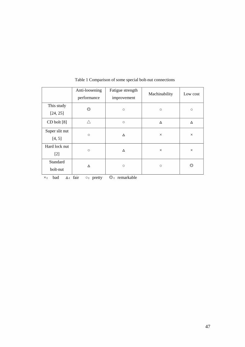
Table 1 shows a comparison of some special bolt-nut connections. Most of the special
bolt-nuts have either more components or very special geometry, leading to a complex
manufacture process and a high cost which is usually more than 3 times of the normal
bolt-nut. The suggested nut in this study can be manufactured as the same way as the
normal nut, and the cost is predicted to be about 1.5 times of the normal nut considering
the modification of thread tap as well as the checking procedure on the pitch difference.
Our previous experimental work clarified that the fatigue life is improved by
introducing a suitable pitch difference under a certain level of stress amplitude [24, 25].
In this study, at first, the effect of pitch difference on the anti-loosening performance
will be studied experimentally, and the most desirable pitch difference will be proposed
taking into account the effect on clamping ability. Furthermore, the fatigue experiments
4
will be carried out to investigate the effect of pitch difference on the improvement of
fatigue life. The finite element analysis will also be applied to discuss the stress status at
bolt thread. Taking the anti-loosening performance and the fatigue life improvement
into account, the most desirable pitch difference will be proposed.
2 Effect of the Pitch Difference on the Nut Rotation
2.1 Bolt-Nut Specimens
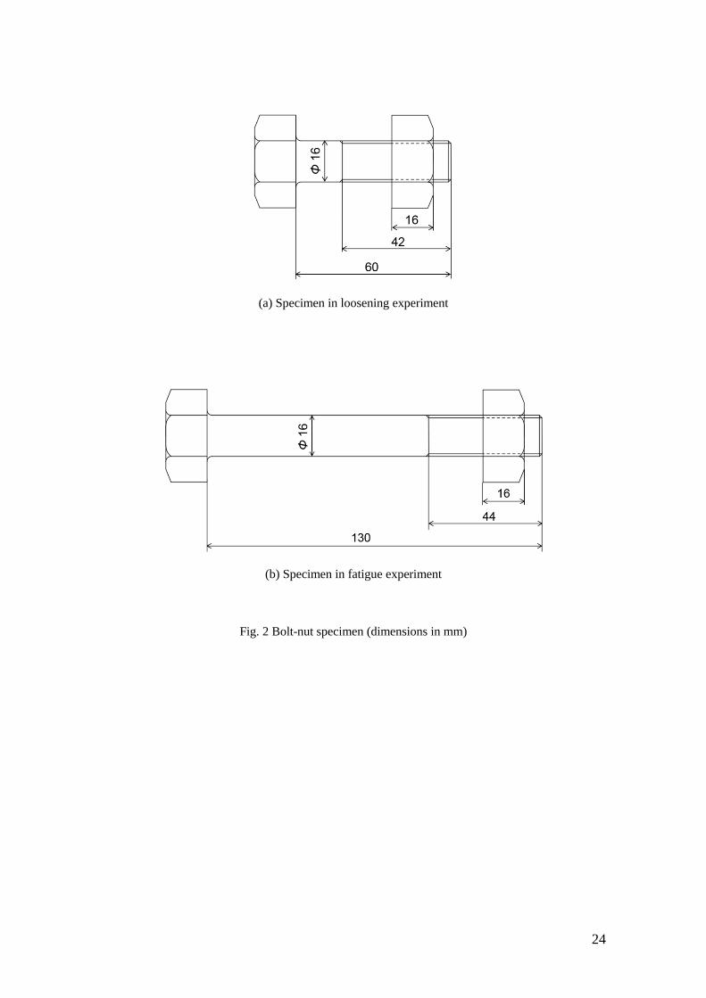
Japanese Industrial Standard (JIS) M16 bolt-nut connections were employed to study
the effect of a slight pitch difference. Figure 2 shows the dimensions of bolt-nut
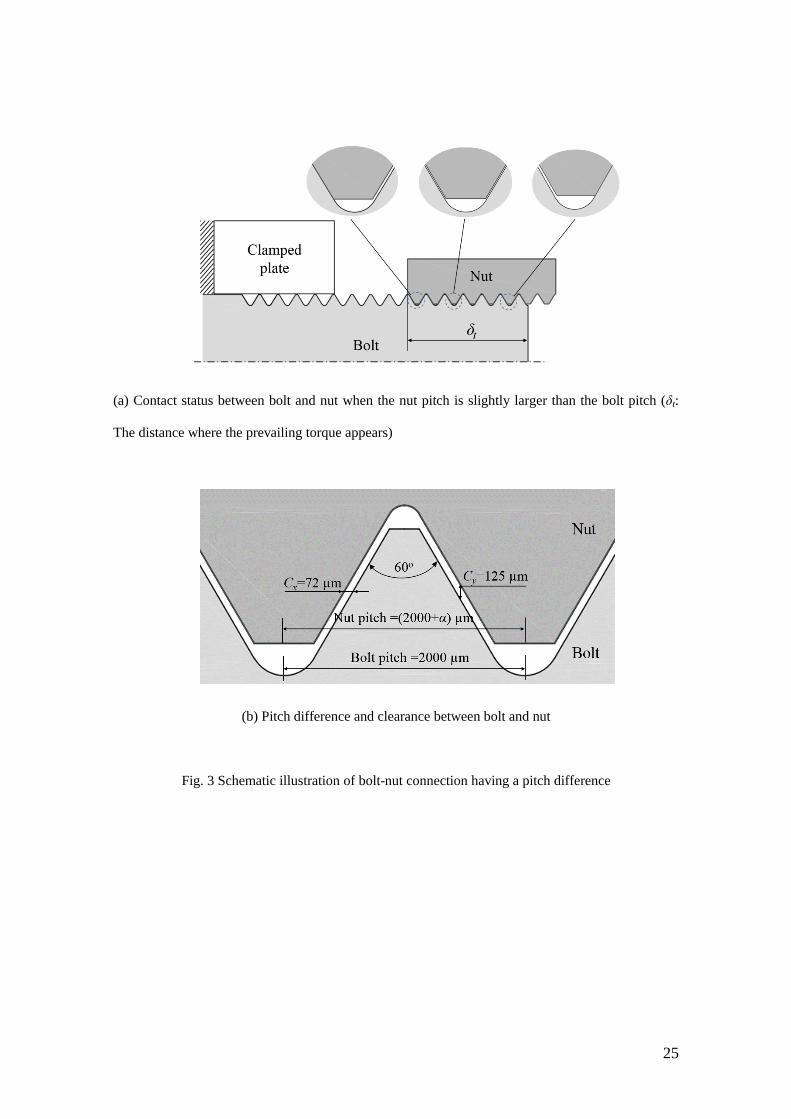
specimen used in this study. Figure 3 shows a schematic illustration of bolt-nut
connection having pitch differences. Usually, standard M16 bolts and nuts have the
same pitch of 2 mm, but herein the nut pitch is slightly larger than the bolt pitch. The
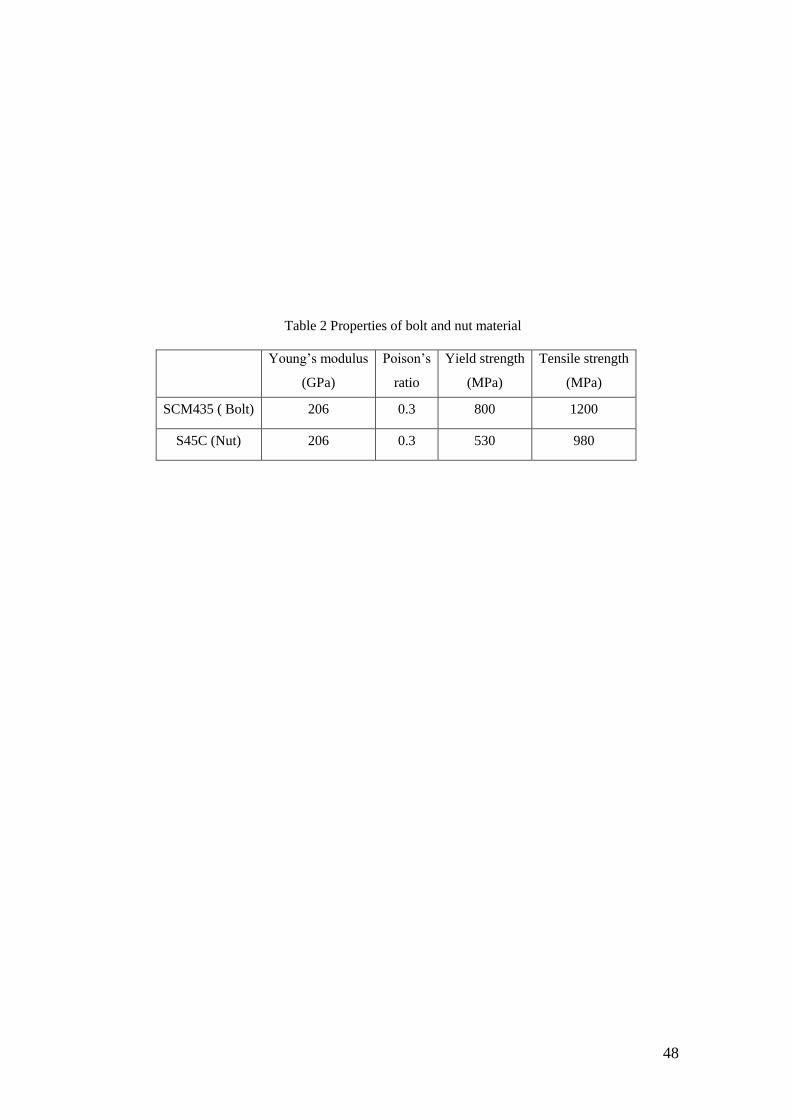
clearance between the bolt-nut threads is equal to 125 μm. The bolt material was
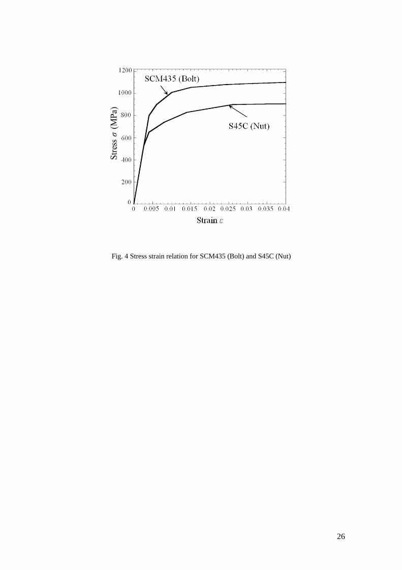
chromium-molybdenum steel SCM435 (JIS), and the nut material was medium carbon
steel S45C (JIS) quenched and tempered, whose properties are indicated in Table 2, and
whose stress-strain curves are shown in Fig. 4, respectively.
Figure 3 (a) also shows a contact status between bolt and nut threads during the
tightening process. As the nut is screwed onto the bolt, the pitch difference is
accumulated. Finally, the first and sixth nut threads become in contact with the bolt
threads as shown in Fig. 3 (a). The distance, δt, where the contact takes place, can be
obtained geometrically using Equations (1) and (2).
2 ,tan
y
c x x
Cn C C
(1)
t cn p (2)
where p is the pitch of bolt (2 mm), α is the pitch difference, nc is the number of nut
thread in contact except for n=1, θ is the thread angle (=60o), ( ) / 2 , and Cx
5
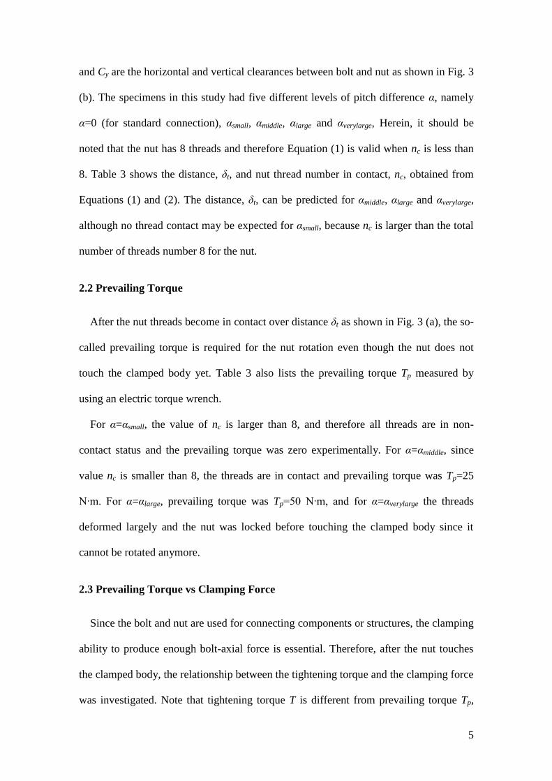
and Cy are the horizontal and vertical clearances between bolt and nut as shown in Fig. 3
(b). The specimens in this study had five different levels of pitch difference α, namely
α=0 (for standard connection), αsmall, αmiddle, αlarge and αverylarge, Herein, it should be
noted that the nut has 8 threads and therefore Equation (1) is valid when nc is less than
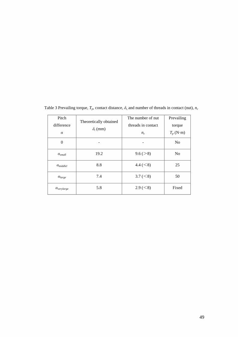
8. Table 3 shows the distance, δt, and nut thread number in contact, nc, obtained from
Equations (1) and (2). The distance, δt, can be predicted for αmiddle, αlarge and αverylarge,
although no thread contact may be expected for αsmall, because nc is larger than the total
number of threads number 8 for the nut.
2.2 Prevailing Torque
After the nut threads become in contact over distance δt as shown in Fig. 3 (a), the so-
called prevailing torque is required for the nut rotation even though the nut does not
touch the clamped body yet. Table 3 also lists the prevailing torque Tp measured by
using an electric torque wrench.
For α=αsmall, the value of nc is larger than 8, and therefore all threads are in non-
contact status and the prevailing torque was zero experimentally. For α=αmiddle, since
value nc is smaller than 8, the threads are in contact and prevailing torque was Tp=25
N∙m. For α=αlarge, prevailing torque was Tp=50 N∙m, and for α=αverylarge the threads
deformed largely and the nut was locked before touching the clamped body since it
cannot be rotated anymore.
2.3 Prevailing Torque vs Clamping Force
Since the bolt and nut are used for connecting components or structures, the clamping
ability to produce enough bolt-axial force is essential. Therefore, after the nut touches
the clamped body, the relationship between the tightening torque and the clamping force
was investigated. Note that tightening torque T is different from prevailing torque Tp,
6
which is defined only before the nut touches the clamped body. To obtain the
relationship between torque and clamping force, the torque was controlled by using an
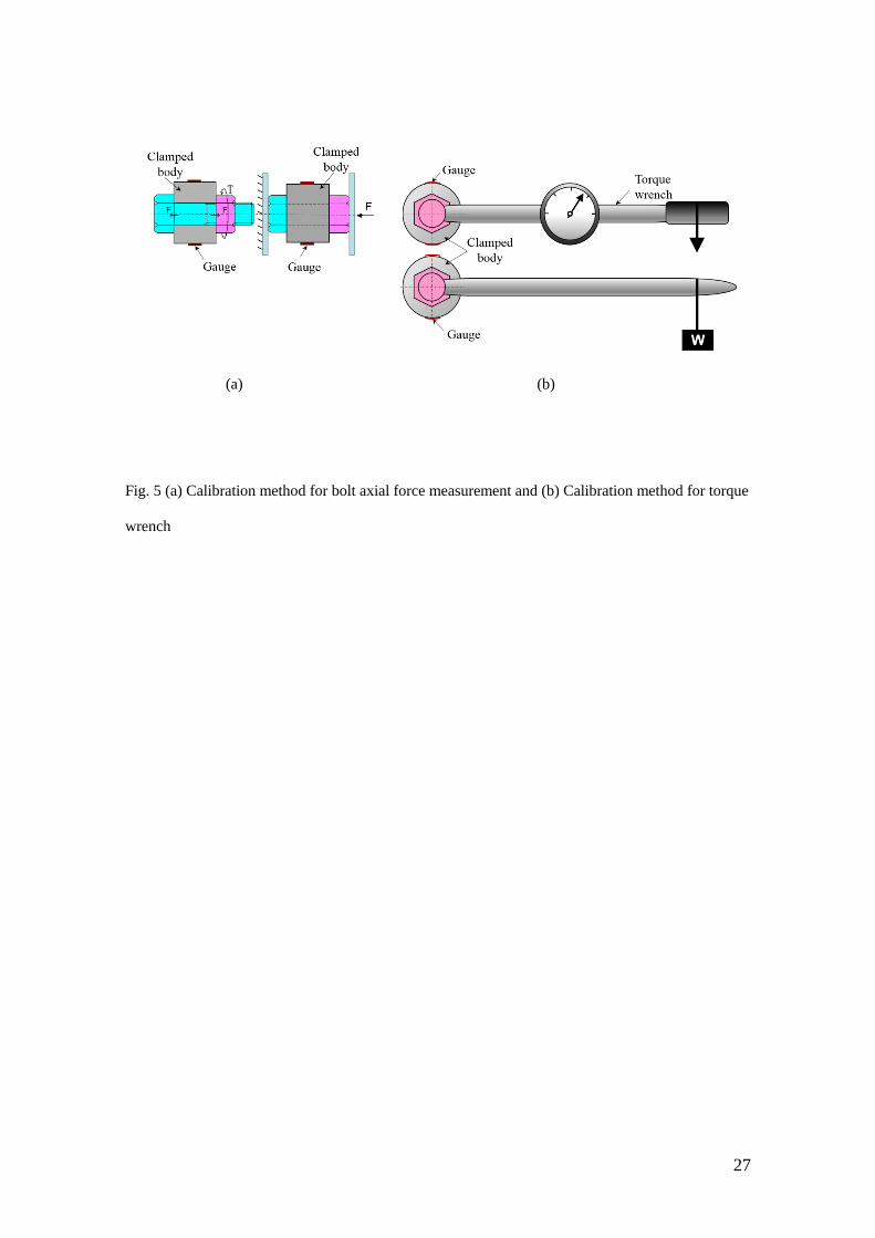
electric torque wrench, and the clamping force was measured by using the strain gauge
attached to the clamped body surface as shown in Fig. 5 (a). The uniaxial strain gauge
with a length of 2 mm KFG-2 (Kyowa Electronic Instruments Co., Ltd.) was used in
this measurement. Before the experiments, calibration tests were performed by
compressing the clamped body to obtain the relationship between the clamping force
and surface strain as shown in Fig. 5 (a). Similar tests were performed to calibrate the
torque wrench as shown in Fig. 5 (b). In order to compare anti-loosening performance
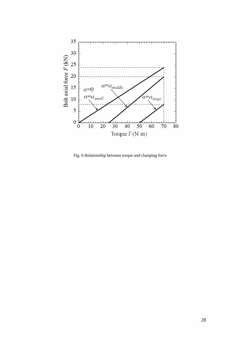
for different pitch differences, the same tightening torque was applied. When the
tightening torque of 70 N·m was applied to the standard bolt-nut (α=0), the bolt-axial
force became 24 kN. The bolt axial force 24 kN is rather smaller compared to the
normal bolt-axial force as the standard bolt-axial force 59.3 kN recommended in [26].
However, if a larger bolt-axial force is used, the effect of α on the anti-loosening
performance cannot be clearly demonstrated because the bolt-nut seizure occurs. In fact,
when a torque of 150 N·m was applied in our preliminary experiments, bolt-nut seizure
was sometimes observed even for α=0 and α=αsmall. This is because in this study,
turning was used for manufacturing nuts, which leads to the bolt-nut seizure occurring
more easily than tapping, which is usually used for manufacturing nuts. The tapping
was not used in this study because of the high cost. However, in the further research, the
tapping nut can be used to prevent the bolt-nut seizure. In this study, therefore, the
smaller tightening torque of 70 N·m is used to compare the anti-loosening ability
conveniently.
Figure 6 shows the tightening torque vs. clamping force as experimentally obtained.
When α=αsmall, the torque-clamping force relationship was same with the one of α=0.
7
When α=αmiddle, the prevailing torque of 25 N∙m was required before the nut touches the
clamped plate. Under the same tightening torque of 70 N∙m, the clamping force was
reduced to 20 kN. When α=αlarge, under a torque of 70 N∙m the axial force decreased
significantly to 8 kN, which was only 1/3 of the axial force of α=0.
3 Loosening Experiment
3.1 Device
Based on the torque-axial force relationship obtained above, the loosening
experiments were performed to investigate the effect of pitch difference on the anti-
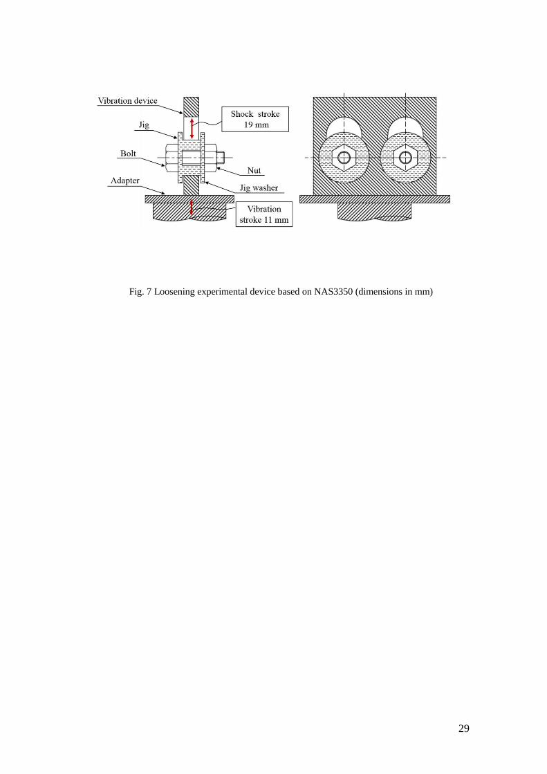
loosening performance. For each pitch difference α, two specimens were tested. As
shown in Fig. 7, the experimental device was an impact-vibration testing machine based
on NAS3350 (National Aerospace Standard), whose vibration frequency was about 30
Hz, and vibration acceleration is 20 g. The maximum vibration cycle of NAS3350 is 30
000, therefore, if the number of vibration cycles was over 30 000, the anti-loosening
performance may be considered to be good enough. A counter connected with the
experimental device shows the number of cycles of vibrations. As states in Section 2.3,
the bolt-axial force 24 kN was considered for the standard bolt-nut, and the
corresponding tightening torque was 70 N∙m. In order to compare the anti-loosening
performance under the same condition, in this paper, the nuts were tightened to the same
torque of 70 N∙m for all the specimens.
3.2 Results
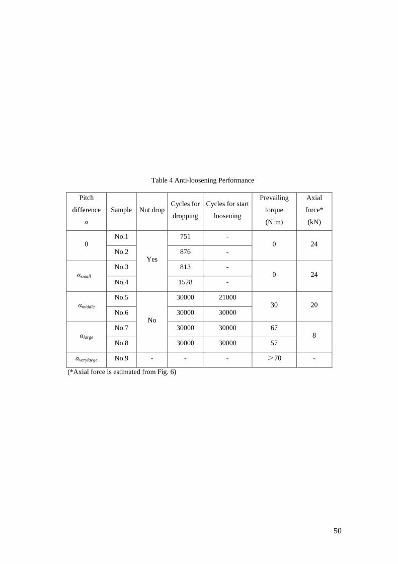
Table 4 lists the number of cycles for the start loosening and the nut dropping. Table
4 also lists the prevailing torque measured in the loosening experiments and the bolt
axial forces estimated from Fig. 6. For α=0 and α=αsmall, the nuts dropped at about 1,000
8
cycles. For α=αmiddle, the nuts did not drop until 30 000 cycles, but the loosening was
observed for one specimen. For α=αlarge, no loosening was observed until 30 000 cycles
although the axial force was estimated to be only 8 kN. It may be concluded that if α is
too small, the anti-loosening cannot be expected and if α is too large, the clamping
ability is not good enough. By considering both the anti-loosening and clamping
abilities, α=αmiddle can be selected as the most suitable pitch difference. It should be
noted that the most desirable pitch difference of α=αmiddle was obtained with a clearance
of Cy=125 μm.
4 Finite Element Analysis
The previous discussion shows that α=αlarge has a good anti-loosening performance
but insufficient clamping ability. This is due to the large deformation of the threads
during the tightening process. To confirm this, an axisymmetric model of the bolt-nut
connection was constructed by using the FEM code MSC.Marc/Mentat 2012. The
material of the bolt was SCM435 and the material of the nut was S45C to match the
experimental conditions. These stress-strain curves are indicated in Fig. 4. Herein, bolt,
nut and clamped body are modeled as three bodies in contact. In the tightening process,
the accumulated pitch difference causes the axial force between the bolt threads
engaged with the nut thread. In this modelling, the bolt head is fixed in the horizontal
direction, and the tightening process is expressed by shifting the nut threads position
discontinuously, one by one, at the pitch interval. As the nut is moving towards the bolt
head, the accumulation of the pitch difference leads to a slight overlap between the bolt
threads and the nut threads. The direct constraints method is invoked in the detection of
contact in MSC. Marc [27], then, the nut is compressed while the bolt is stretched in the
simulation. In this way, the axial force between the bolt threads can be investigated step
by step as the nut is shifted onto the bolt. It should be noted that this axisymmetric
9
simulation may include some numerical errors but the real axial force between the bolt
threads is difficult to be measured experimentally because the nut is engaged at this
position. The multifrontal sparse solver was used. The isotropic hardening law was
assumed with von Mises yield criterion. Friction coefficient of 0.3 was assumed and
Coulomb friction was used. In the next sub-section, the results for α=αmiddle and
α=αverylarge will be compared.
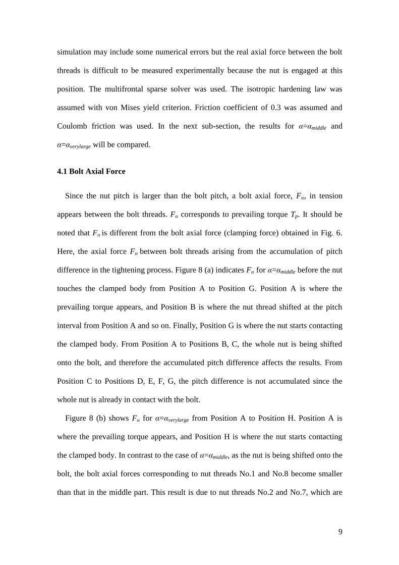
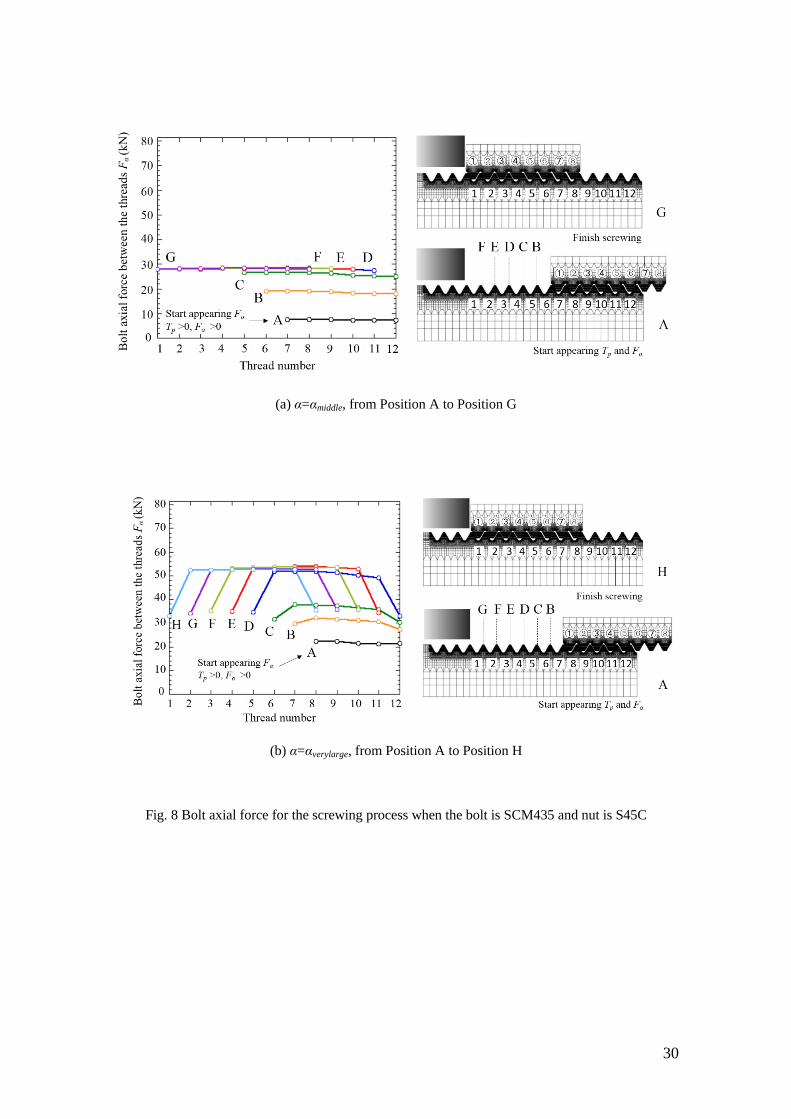
4.1 Bolt Axial Force
Since the nut pitch is larger than the bolt pitch, a bolt axial force, Fα, in tension
appears between the bolt threads. Fα corresponds to prevailing torque Tp. It should be
noted that Fα is different from the bolt axial force (clamping force) obtained in Fig. 6.
Here, the axial force Fα between bolt threads arising from the accumulation of pitch
difference in the tightening process. Figure 8 (a) indicates Fα for α=αmiddle before the nut
touches the clamped body from Position A to Position G. Position A is where the
prevailing torque appears, and Position B is where the nut thread shifted at the pitch
interval from Position A and so on. Finally, Position G is where the nut starts contacting
the clamped body. From Position A to Positions B, C, the whole nut is being shifted
onto the bolt, and therefore the accumulated pitch difference affects the results. From
Position C to Positions D, E, F, G, the pitch difference is not accumulated since the
whole nut is already in contact with the bolt.
Figure 8 (b) shows Fα for α=αverylarge from Position A to Position H. Position A is
where the prevailing torque appears, and Position H is where the nut starts contacting
the clamped body. In contrast to the case of α=αmiddle, as the nut is being shifted onto the
bolt, the bolt axial forces corresponding to nut threads No.1 and No.8 become smaller
than that in the middle part. This result is due to nut threads No.2 and No.7, which are

10
also in contact as well as threads No.1 and No.8. Under α=αmiddle only nut threads No.1
and No.8 are in contact with bolt threads.
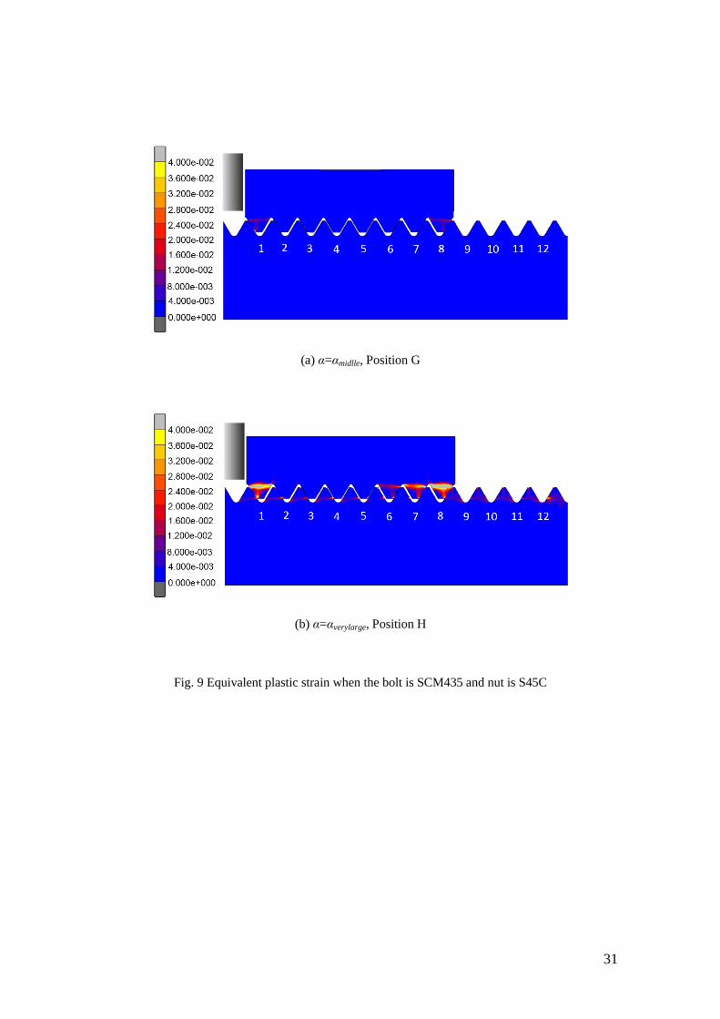
4.2 Plastic Deformation
Figure 9 (a) shows the equivalent plastic strain of threads for α=αmiddle at Position G.
Similarly, Fig. 9 (b) shows the equivalent plastic strain of threads for α=αverylarge at
Position H. It may be concluded that too large pitch difference α=αverylarge may cause the
large deformation at nut threads resulting in deterioration of bolt clamping ability. A
suitable pitch difference may cause the reasonable deformation and may not reduce the
clamping force.
5 Effect of the Pitch Difference on the Fatigue Strength
5.1 Results and Discussion
Our previous experiments clarified that the fatigue life was improved by introducing
a pitch difference α=αsmall under a certain level of stress amplitude [24-25]. According
to the loosening experiments, it was found that α=αmiddle was the most desirable pitch
difference to realize the anti-loosening performance. To improve the fatigue life as well
as the anti-loosening performance, fatigue experiments were conducted systematically
for three types of specimens, i.e. α=0, α=αsmall and α=αmiddle with various levels of stress
amplitude.
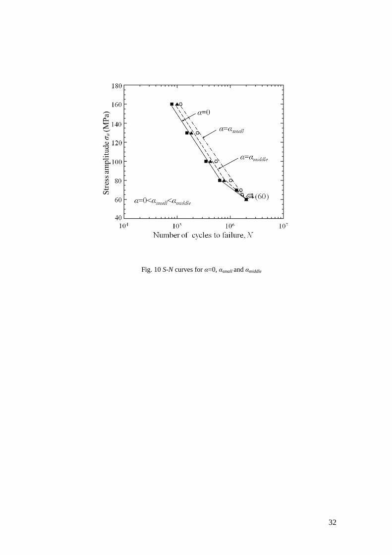
The 392 kN Servo Fatigue Testing Machine with a frequency of 8 Hz was used in this
study. The pulsating tension fatigue experiments with a stress ratio of R=0.14-0.56 were
conducted under a fixed average stress of σm= 213 MPa. Figure 10 shows the obtained
S-N curves. Independent of α, it was found that the fatigue limit at N=2×10⁶ cycles was
60 MPa.
11
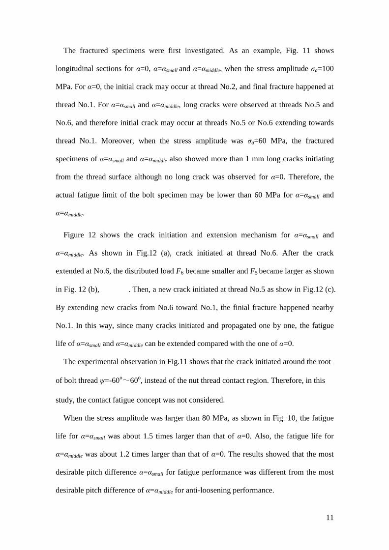
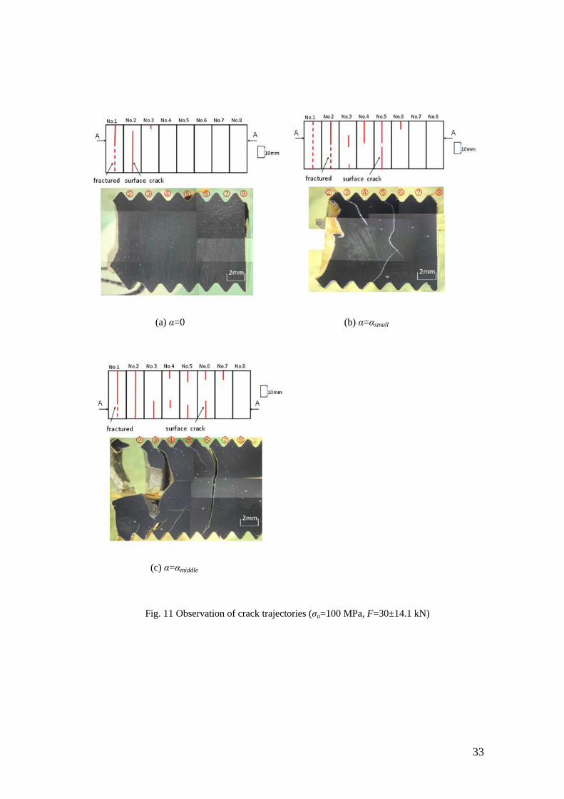
The fractured specimens were first investigated. As an example, Fig. 11 shows
longitudinal sections for α=0, α=αsmall and α=αmiddle, when the stress amplitude σa=100
MPa. For α=0, the initial crack may occur at thread No.2, and final fracture happened at
thread No.1. For α=αsmall and α=αmiddle, long cracks were observed at threads No.5 and
No.6, and therefore initial crack may occur at threads No.5 or No.6 extending towards
thread No.1. Moreover, when the stress amplitude was σa=60 MPa, the fractured
specimens of α=αsmall and α=αmiddle also showed more than 1 mm long cracks initiating
from the thread surface although no long crack was observed for α=0. Therefore, the
actual fatigue limit of the bolt specimen may be lower than 60 MPa for α=αsmall and
α=αmiddle.
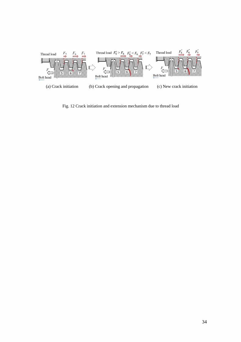
Figure 12 shows the crack initiation and extension mechanism for α=αsmall and
α=αmiddle. As shown in Fig.12 (a), crack initiated at thread No.6. After the crack
extended at No.6, the distributed load F6 became smaller and F5 became larger as shown
in Fig. 12 (b), . Then, a new crack initiated at thread No.5 as show in Fig.12 (c).
By extending new cracks from No.6 toward No.1, the finial fracture happened nearby
No.1. In this way, since many cracks initiated and propagated one by one, the fatigue
life of α=αsmall and α=αmiddle can be extended compared with the one of α=0.
The experimental observation in Fig.11 shows that the crack initiated around the root
of bolt thread ψ=-60o~60
o, instead of the nut thread contact region. Therefore, in this
study, the contact fatigue concept was not considered.
When the stress amplitude was larger than 80 MPa, as shown in Fig. 10, the fatigue
life for α=αsmall was about 1.5 times larger than that of α=0. Also, the fatigue life for
α=αmiddle was about 1.2 times larger than that of α=0. The results showed that the most
desirable pitch difference α=αsmall for fatigue performance was different from the most
desirable pitch difference of α=αmiddle for anti-loosening performance.
12
In Fig.10, there are different fatigue data between α=αsmall and α=0 because the stress
status at bolt thread changed when α=αsmall was introduced. On the other hand, as shown
in Fig.6, since there was no prevailing torque appears in the tightening process for
α=αsmall, it has the same torque-axial force relationship with the normal specimen α=0.
The effect of pitch difference on the fatigue life is different from the effect on tightening
process. This is because that the fatigue damage is mainly controlled by the stress
amplitude produced by the axial loading at the bolt threads.
5.2 Strength Analysis
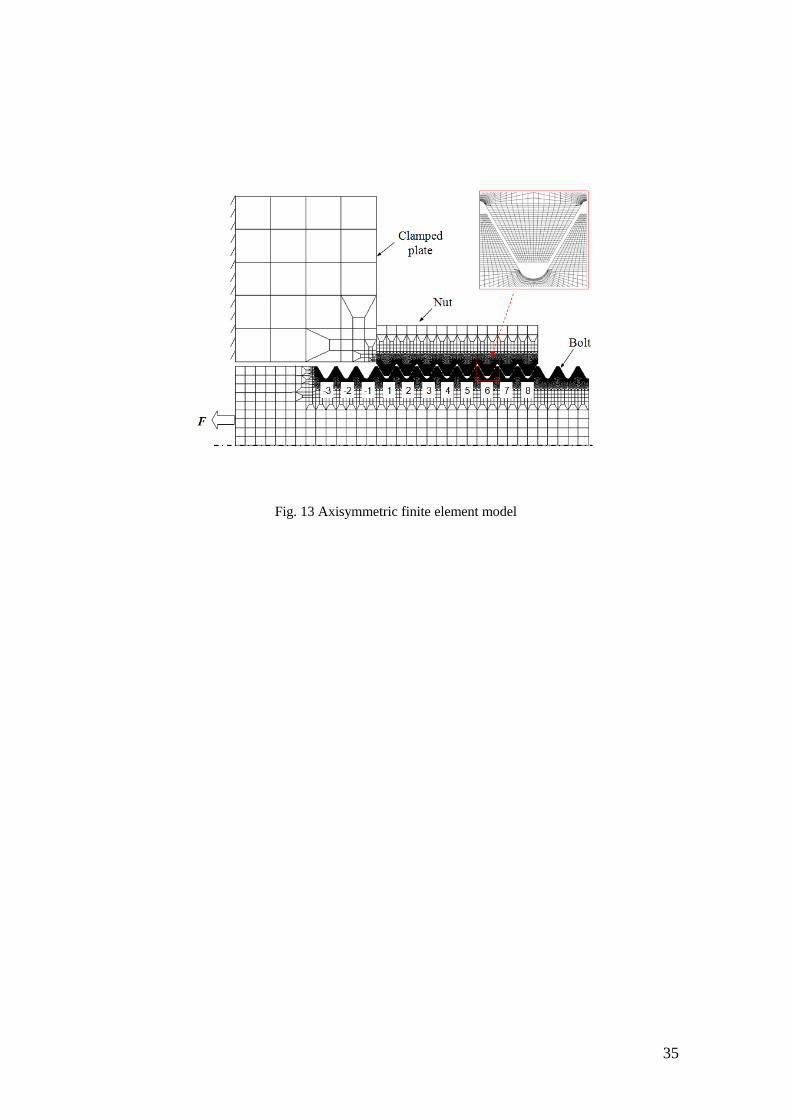
To clarify the effect of the pitch difference on the stress at the bolt threads, the
elastic-plastic FE analyses were performed for α=0 and α=αsmall under load F=30±14.1
kN. The axisymmetric finite element model of bolt-nut connection is shown in Fig. 13.
A cylindrical clamped plate was modeled with an inner diameter of 17.5 mm, outer
diameter of 50 mm and thickness of 35 mm. The material of the bolt and clamped body
was SCM435 and the material of the nut was S45C to match the experimental
conditions. These stress-strain curves are indicated in Fig. 4. The bolt, nut and clamped
body were modeled as three contact bodies. A fine mesh was created at the root of bolt
thread with the size of 0.015mm×0.01mm, and 4-noded, axisymmetric solid, full
integration element was used. The isotropic hardening law was assumed with von Mises
yield criterion. Friction coefficient of 0.3 with Coulomb friction was used for the
analysis. The clamped body was fixed in the horizontal direction, and cyclic load
F=30±14.1 kN was applied on the bolt head as shown in Fig. 13. Then, the stress status
under the maximum load F=30+14.1 kN and the minimum load F=30-14.1 kN was
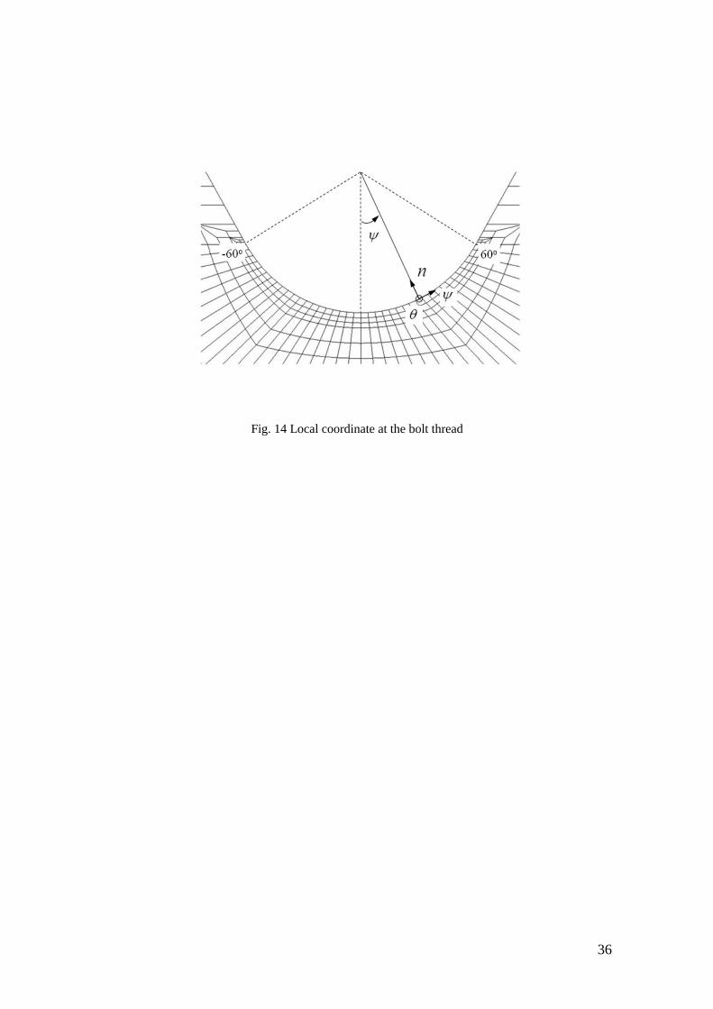
considered to obtain the endurance limit diagrams. Figure 14 defines the angle ψ at the
bolt thread. In the FE analysis σψmax was the stress σψ at each thread under the maximum
13
load, and σψmin was the stress σψ at each thread under the minimum load. The stress
amplitude and mean stress were investigated at the same angle ψ where the maximum
stress amplitude appears, since the stress amplitude is the most important parameter for
fatigue analysis. The mean stress σm and stress amplitude σa at each thread are defined as
follows:
2
max min
m
,
2
max min
a
(3)
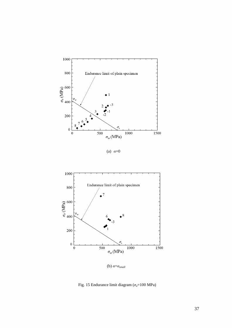
The maximum stress amplitude and the mean stress at each bolt thread are plotted in
Fig. 15 and compared with Soderberg line representing the endurance limit for plain
specimen. Figure 15 indicates that the stress amplitude at thread No.1 for α=αsmall is
much smaller than that of α=0 although the stress amplitudes of threads No.4 to No.8
are much larger than those of α=0. Therefore, the cracks may appear faster at No.4 to
No.8 for α=αsmall, but the fatigue life time is extended as shown in Fig. 10 since the
crack propagation from threads No.8 to No.1 needs longer time.
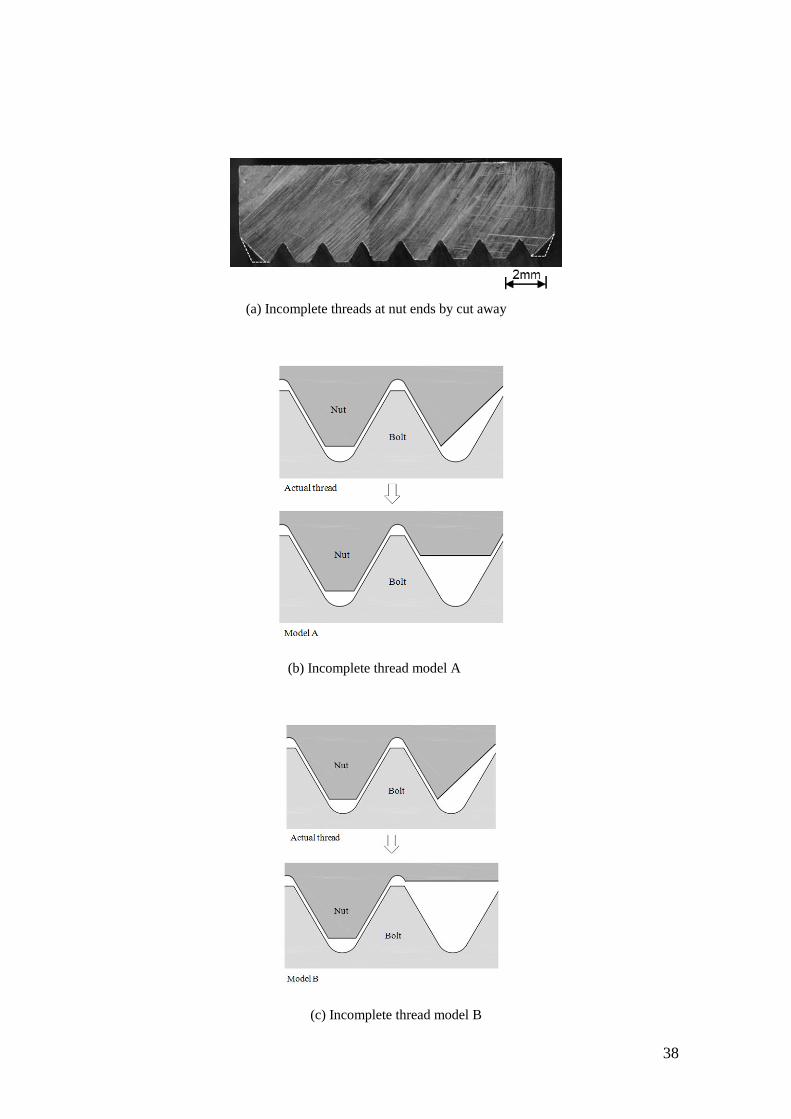
6 Effect of incomplete nut thread
In the above discussion, the complete thread model of 8-thread-nuts were considered
by FE analyses, but usually as shown in Fig. 16 (a) both ends of nuts have chamfered
corners, which are required to make bolt inserted smoothly. This types of nuts were
used in the fatigue experiments. Therefore, the chamfered corner was modeled first by
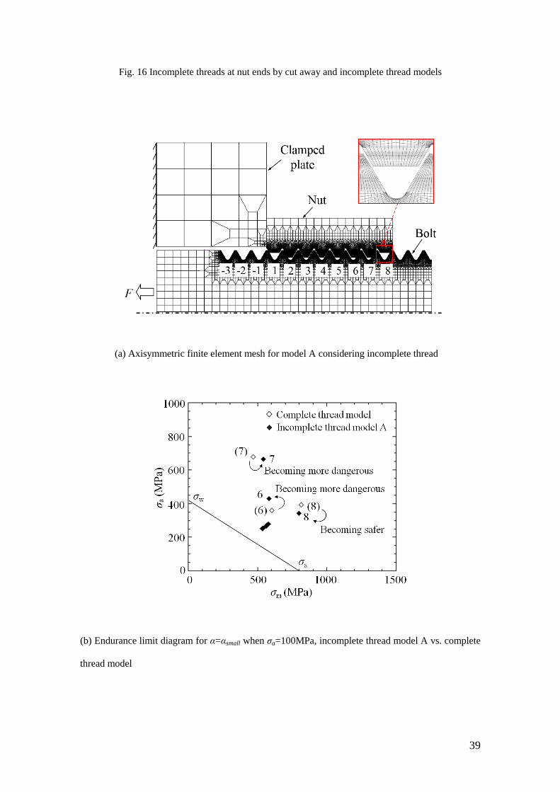
an incomplete thread model A as shown in Fig. 16 (b). Figure 17 shows FE mesh for
model A and the endurance limit diagram, when α=αsmall and σa= 100 MPa. From Fig.
17 (b), it can be seen that the stress in thread No.8 decreases and the stress in thread
No.6 increases. However, the stress in thread No.6 is not the most dangerous because
thread No.8 is still in contact with a nut thread.
14
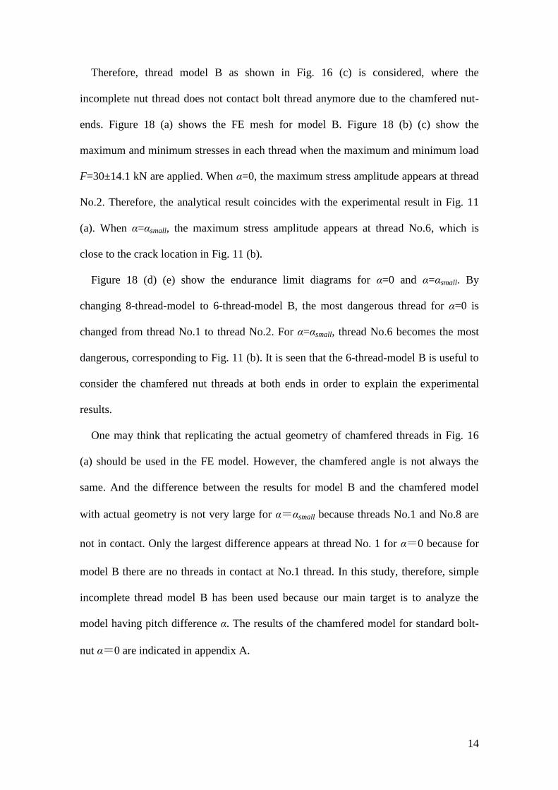
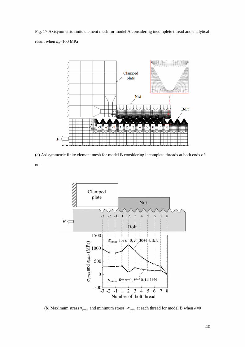
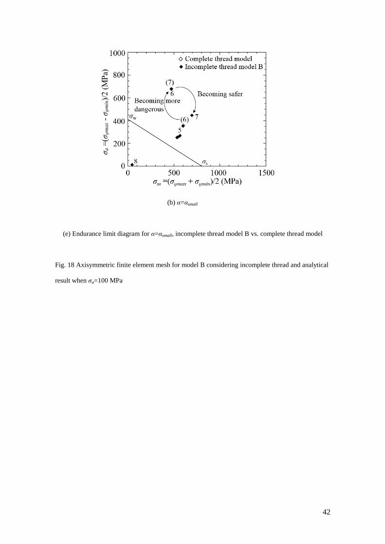
Therefore, thread model B as shown in Fig. 16 (c) is considered, where the
incomplete nut thread does not contact bolt thread anymore due to the chamfered nut-
ends. Figure 18 (a) shows the FE mesh for model B. Figure 18 (b) (c) show the
maximum and minimum stresses in each thread when the maximum and minimum load
F=30±14.1 kN are applied. When α=0, the maximum stress amplitude appears at thread
No.2. Therefore, the analytical result coincides with the experimental result in Fig. 11
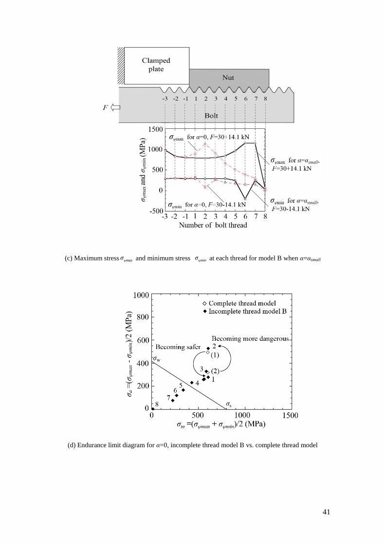
(a). When α=αsmall, the maximum stress amplitude appears at thread No.6, which is
close to the crack location in Fig. 11 (b).
Figure 18 (d) (e) show the endurance limit diagrams for α=0 and α=αsmall. By
changing 8-thread-model to 6-thread-model B, the most dangerous thread for α=0 is
changed from thread No.1 to thread No.2. For α=αsmall, thread No.6 becomes the most
dangerous, corresponding to Fig. 11 (b). It is seen that the 6-thread-model B is useful to
consider the chamfered nut threads at both ends in order to explain the experimental
results.
One may think that replicating the actual geometry of chamfered threads in Fig. 16
(a) should be used in the FE model. However, the chamfered angle is not always the
same. And the difference between the results for model B and the chamfered model
with actual geometry is not very large for α=αsmall because threads No.1 and No.8 are
not in contact. Only the largest difference appears at thread No. 1 for α=0 because for
model B there are no threads in contact at No.1 thread. In this study, therefore, simple
incomplete thread model B has been used because our main target is to analyze the
model having pitch difference α. The results of the chamfered model for standard bolt-
nut α=0 are indicated in appendix A.
15
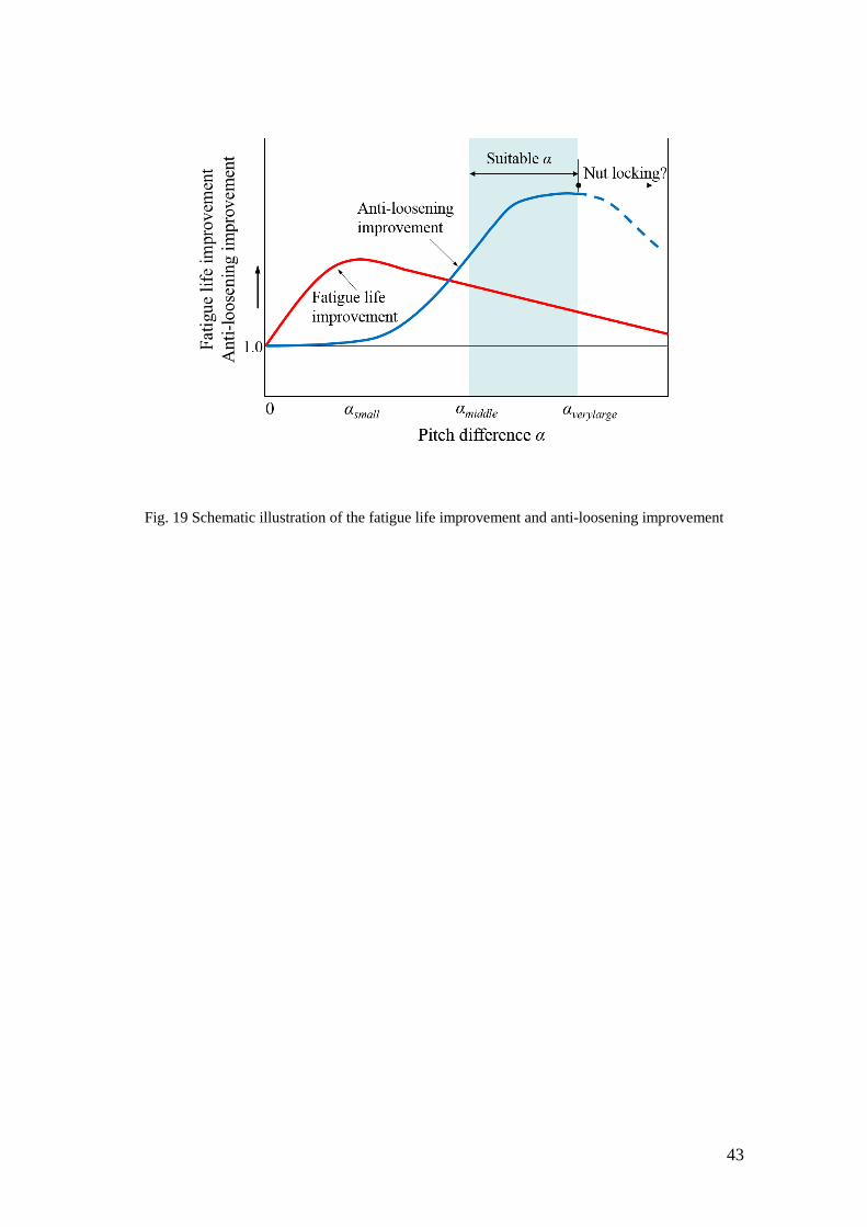
7 Suitable Pitch Difference
The main goal of this study is to find out a suitable pitch difference in order to
improve both anti-loosening effect and fatigue life. Figure 19 shows a schematic
illustration of the fatigue life improvement and anti-loosening improvement by varying
the pitch difference when the results of α=0 are regarded as the reference level. On one
hand, to improve the fatigue life, the most desirable pitch difference may be close to
αsmall as shown in Fig. 10. On the other hand, to improve the anti-loosening
performance, the most desirable pitch difference should be larger than αmiddle and close
to αlarge as shown in Table 4, although the nut locking phenomenon may happen if α is
over αverylarge. Therefore, a suitable range for α can be indicated as shown in Fig. 19.
In this study, the bolt material SCM435 and nut material S45C are assumed. The
stress-strain curves are indicated in Fig. 4. This design can be applied to bolt-nut
connections made in other materials which have suitable elastic-plastic properties since
the plastic deformation is required in order to realize the anti-loosening performance.
8 Conclusions
In this study, a slight pitch difference α was considered for the M16 bolt-nut
connections. The loosening experiments as well as the fatigue experiments were
conducted under different pitch differences. Finite element analysis was used to
investigate the stress and deformation at the bolt threads and the fatigue strength. The
conclusions can be summarized as follows:
(1) Considering both the anti-loosening performance and the clamping ability, α=αmiddle
is found to be the most desirable pitch difference. This is because the nuts did not drop
for α=αmiddle without losing clamping ability.
(2) The anti-loosening experiments show that the nuts did not drop for α=αlarge, but
16
clamping ability is deteriorated. FEA shows that for α=αverylarge, the large plastic
deformation happens at threads of nut.
(3) It is found that α=αsmall is the most desirable pitch difference to extend the fatigue
life of the bolt-nut connection. Compared with the standard bolt-nut connection, the
fatigue life for α=αsmall can be extended to about 1.5 times.
(4) The 6-thread-model as shown in Fig. 18 is useful for analyzing 8-thread-nut model
because nuts always have chamfered threads at both ends. Then, the results are in good
agreement with the experimental results.
(5) A suitable pitch difference to improve both anti-loosening and fatigue life can be
illustrated as shown in Fig. 19.
The errors and uncertainties associated with the measurements or predictions are
always of concern in a study of this nature. In the loosening experiment, two specimens
with the same pitch difference were tested together in order to avoid the uncertainties.
In the fatigue experiment in Fig. 10, the S-N curves may have variations but they are
distinct depending on the pitch difference. In the axisymmetric FE modelling may have
some errors but previously one of the authors have compared the load distributions in
bolt threads between the axisymmetric modelling and the three-dimensional modelling.
Then, the relative errors between the two models are found to be less than 12% [28].
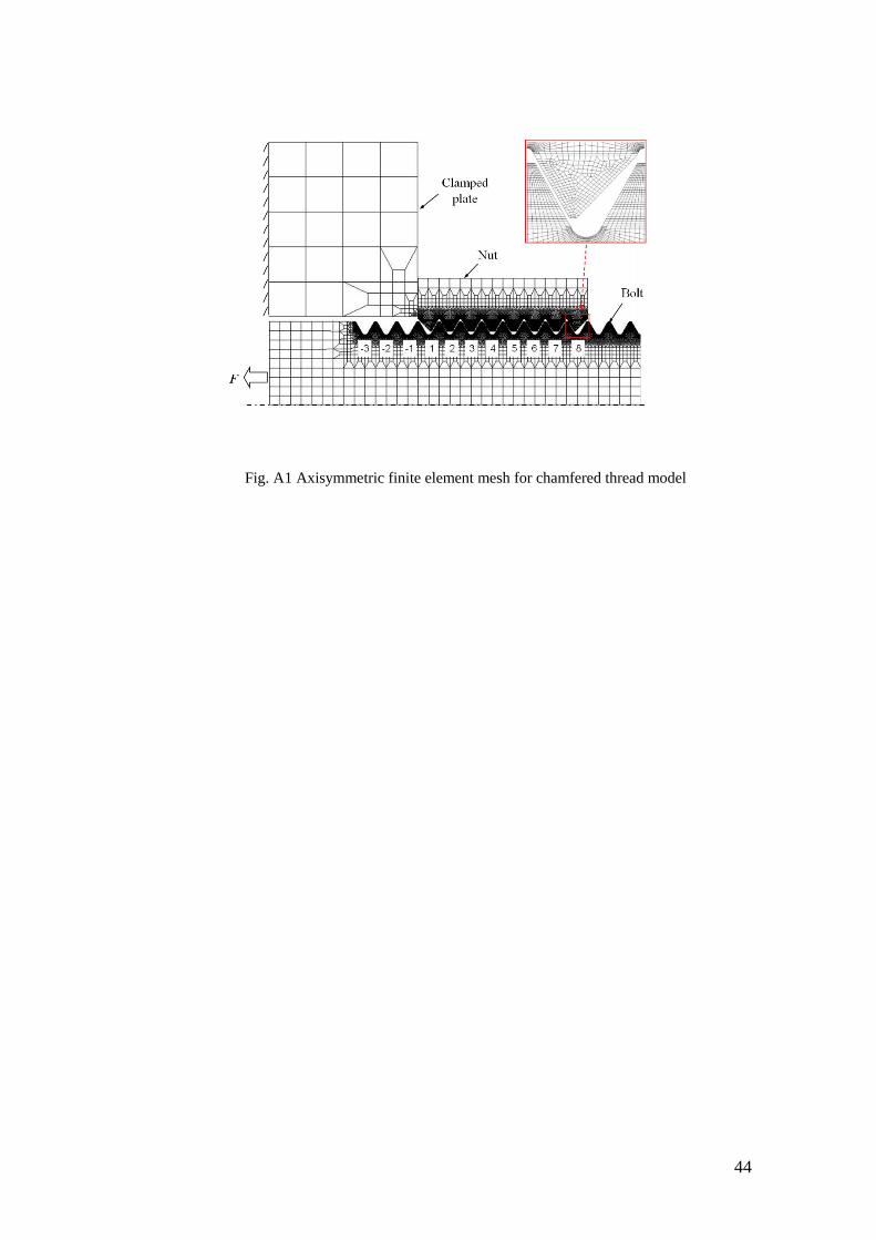
Appendix A: The results for chamfered model
Figure A1 shows the chamfered model replicating the actual geometry in Fig. 16 (a).
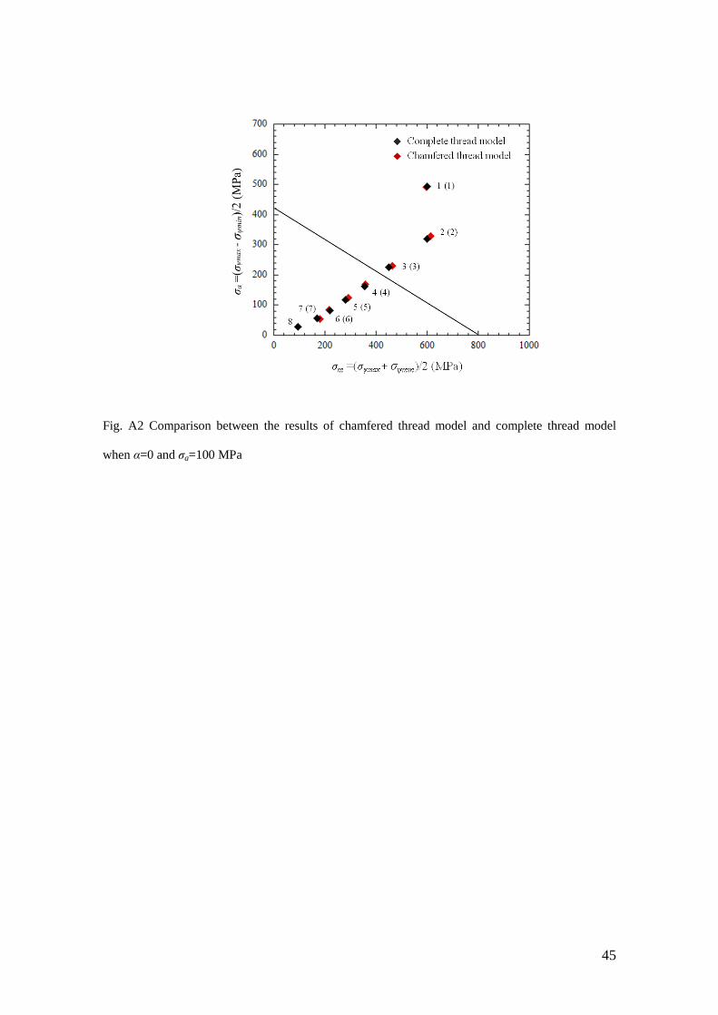
Figure A2 shows the results of the chamfered model in comparison with the results of
the complete thread model in Fig. 13 when α=0. It is seen that because of no contact at
thread No.8 in the chamfered model, mean stress σm and stress amplitude σa increase
except at thread No.1. Since the rigidity of nut thread No.1 decreases in the chamfered
17
model, the stress at bolt thread No.1 does not change very much.
Acknowledgments
The authors wish to express their thanks to the member of their group, Mr. Yu-Ichiro
Akaishi and Mr. Yang Yu for their assistance in this study. The authors acknowledge
the international collaboration grant funded by Commissie Wetenschappelijk Onderzoek
(CWO), Faculty of Engineering and Architecture, Ghent University. The research for
this paper was financially supported by the Japanese Ministry of Education research
expenses [grant number 23560164]; and Kitakyushu Foundation for the Advancement
of Industry Science and Technology.
References
[1] Bhattacharya, A., Sen, A., and Das, S., An Investigation on the Anti-Loosening
Characteristics of Threaded Fasteners under Vibratory Conditions, Mechanism and
Machine Theory, 2010; 45, pp. 1215-1225. DOI:
10.1016/j.mechmachtheory.2008.08.004.
[2] Hard Lock Kogyo KK, Hard Lock Nut, Japan Patent 2002–195236, 2002 (In
Japanese).
[3] Izumi, S., Yokoyama, T., Iwasaki, A., and Sakai, S., Three-Dimensional Finite
Element Analysis of Tightening and Loosening Mechanism of Threaded Fastener,
Engineering Failure Analysis, 2005; 12(4), pp. 604-615. DOI:
10.1016/j.engfailanal.2004.09.009.
[4] Izumi, S., Yokoyama, T., Teraoka, T., Iwasaki, A., Sakai, S., Saito, K., Nagawa, M.,
and Noda, H., Verification of Anti-loosening Performance of Super Slit Nut by Finite
Element Method, Transaction of the Japan Society of Mechanical Engineers, 2005;
703(71), pp. 380-386, (in Japanese).
18
[5] Chen, D. H., Shimizu, E., and Masuda, K., Relation between Thread Deformation
and Anti-Loosening Effect for Nut with Circumference Slits, Transaction of the Japan
Society of Mechanical Engineers, 2012; 788(78), pp. 390-402. DOI:
10.1299/kikaia.78.390.
[6] Noda, N.-A., Xiao, Y., and Kuhara M., Optimum Design of Thin Walled Tube on
the Mechanical Performance of Super Lock Nut, Journal of Solid Mechanics and
Materials Engineering, 2008; 2(6), pp. 780-791. DOI: 10.1299/jmmp.2.780.
[7] Ranjan, B. S. C., Vikranth, H. N., and Ghosal, A., A Novel Prevailing Torque
Threaded Fastener and Its Analysis, ASME Journal of Mechanical Design, 135(10),
101007, 2013. DOI: 10.1115/1.4024977.
[8] Nishida, S.-I., Urashima, C., and Tamasaki, H., A New Method for Fatigue Life
Improvement of Screws, European Structural Integrity Society, 1997; 22, pp. 215-225,
DOI: 10.1016/S1566-1369(97)80021-0.
[9] Nishida, S.-I., Screw Connection Having Improved Fatigue Strength, United States
Patent, 1980; No. 4,189,975.
[10] Majzoobi, G. H., Farrahi, G. H., and Habibi, N., Experimental Evalution of the
Effect of Thread Pitch on Fatigue Life of Bolts, International Journal of Fatigue, 2005;
27(2), pp. 189-196. DOI: 10.1016/j.ijfatigue.2004.06.011.
[11] Noda, N.-A., Xiao, Y., and Kuhara M., The Reduction of Stress Concentration by
Tapering Threads, Journal of Solid Mechanics and Materials Engineering, 2011; 8(5),
pp. 397-408. DOI: 10.1299/jmmp.5.397.
[12] Hirai, K. and Uno, N.: Fatigue Strength of Super High Strength Bolt. Journal of
Structural Engineering, 2005; 595, pp. 117-122.
[13] Pedersen, N. L, Overall Bolt Stress Optimization. The Journal of Strain Analysis
for Engineering Design, 2013; 48(3), pp. 155-165.
19
[14] Zhou, W., Zhang, R., Ai, S., He, R., Pei, Y., and Fang, D., Load Distribution in
Threads of Porous Metal-ceramic Functionally Graded Composite Joints Subjected to
Thermomechanical Loading. Composite Structures, 2015; 134, pp. 680-688.
[15] Li, G., Zhang, C., Hu, H., and Zhang, Y., Optimization Study of C/SiC Threaded
Joints. International Journal of Applied Ceramic Technology, 2014; 11(2), pp. 289-293.
[16] Lee, C.-H., Kim, B.-J., and Han, S.-Y., Mechanism for Reducing Stress
Concentrations in Bolt-Nut Connectors. International Journal of Precision Engineering
and Manufacturing, 2014; 15(7), pp. 1337-1343.
[17] Chakherlou, T. N., Maleki, H. N., Aghdam, A. B., and Abazadeh, B., Effect of Bolt
Clamping Force on the Fracture Strength of Mixed Mode Fracture in an Edge Crack
with Different Sizes: Experimental and Numerical Investigations. Materials and Design,
2013; 45, pp. 430-439.
[18] Stromeyer, C. E., Stress Distribution in Bolts and Nuts. Trans Inst. N. A., 1918; 60,
pp. 112-115.
[19] Sopwith, D. G., The Distribution of Load in Screw Threads. Proceedings of the
Institution of Mechanical Engineers, 1948; 159, pp. 373-383.
DOI: 10.1243/PIME_PROC_1948_159_030_02
[20] Sparling, L. G. M., Improving the Strength of Screw Fasteners. Chart. Mech.
Engrs, 1982; 29, pp. 58-59.
[21] Patterson, E. A. and Kenny, B., A Modification to the Theory for the Load
Distribution in Conventional Nuts and Bolts, The Journal of Strain Analysis for
Engineering Design, 1986; 21(1), pp. 17-23. DOI: 10.1243/03093247V211017.
[22] Kenny, B. and Patterson, E. A., Stress Analysis of Some Nut-bolt Connections with
Modifications to the Nut Thread Form, The Journal of Strain Analysis for Engineering
Design, 1985; 20(1), pp. 35-40. DOI: 10.1243/03093247V201035.
20
[23] Maruyama, K., Stress Analysis of a Bolt-Nut Joint by the Finite Element Method
and the Copper-Electroplating Method: 3rd Report, Influence of Pitch Error or Flank
Angle Error, Transaction of the Japan Society of Mechanical Engineers, 1973; 19(130),
pp. 360-368. DOI: 10.1299/jsme1958.19.360.
[24] Akaishi, Y.-I., Chen, X., Yu, Y., Tamasaki, H., Noda, N.-A., Sano, Y., and Takase,
Y., Fatigue Strength Analysis for Bolts and Nuts Which Have Slightly Different Pitches
Considering Clearance, Transactions of Society of Automotive Engineers of Japan,
2013; 44(4), pp. 1111-1117, (in Japanese).
[25] Chen, X., Noda, N.-A., Wahab, M. A., Akaishi, Y.-I., Sano, Y., Takase, Y., and
Fekete, G., Fatigue Failure Analysis in Bolt-Nut Connection Having Slight Pitch
Difference Using Experiments and Finite Element Method, Acta Polytechnica
Hungarica, 2015; 12(8), pp. 61-79.
[26] Tohnichi torque handbook, Vol.7, Chapter 2 Bolt Tightening, pp. 34-37, (in
Japanese).
[27] Marc 2012, Theory and user information, MSC. Software Corporation, 2012, Vol.
A, pp. 540-581.
[28] Noda, N.-A., Kuhara, M., Xiao, Y., Noma, S., Saito, K., Nagawa, M., Yumoto, A.
and Ogasawara, A., Stress Reduction Effect and Anti-loosening Performance of Outer
Cap Nut by Finite Element Method, Journal of Solid Mechanics and Materials
Engineering, 2008; 2(6), pp. 801-811.
21
Figure Captions List
Fig. 1 Contact status between bolt and nut threads before and after loading (
contact)
Fig. 2 Bolt-nut specimen (dimensions in mm)
Fig. 3 Schematic illustration of bolt-nut connection having a pitch difference
Fig. 4 Stress strain relation for SCM435 (Bolt) and S45C (Nut)
Fig. 5 (a) Calibration method for bolt axial force measurement and (b) Calibration
method for torque wrench
Fig. 6 Relationship between torque and clamping force
Fig. 7 Loosening experimental device based on NAS3350 (dimensions in mm)
Fig. 8 Bolt axial force for the screwing process when the bolt is SCM435 and nut is
S45C
Fig. 9 Equivalent plastic strain when the bolt is SCM435 and nut is S45C
Fig. 10 S-N curves for α=0, αsmall and αmiddle
Fig. 11 Observation of crack trajectories (σa=100 MPa, F=30±14.1 kN)
Fig. 12 Crack initiation and extension mechanism due to thread load
Fig. 13 Axisymmetric finite element model
Fig. 14 Local coordinate at the bolt thread
Fig. 15 Endurance limit diagram (σa=100 MPa)
Fig. 16 Incomplete threads at nut ends by cut away and incomplete thread models
Fig. 17 Axisymmetric finite element mesh for model A considering incomplete thread
and analytical result
22
Fig. 18 Axisymmetric finite element mesh for model B considering incomplete thread
and analytical result
Fig. 19 Schematic illustration of the fatigue life improvement and anti-loosening
improvement
Fig. A1 Axisymmetric finite element mesh for chamfered thread model
Fig. A2 Comparison between the results of chamfered thread model and complete
thread model when α=0 and σa=100 MPa
23
Before loading After loading
(a) The nut pitch is larger than the bolt pitch
Before loading After loading
(b) The nut pitch is smaller than the bolt pitch
Fig. 1 Contact status between bolt and nut threads before and after loading ( contact)
24
(a) Specimen in loosening experiment
(b) Specimen in fatigue experiment
Fig. 2 Bolt-nut specimen (dimensions in mm)
25
(a) Contact status between bolt and nut when the nut pitch is slightly larger than the bolt pitch (δt:
The distance where the prevailing torque appears)
(b) Pitch difference and clearance between bolt and nut
Fig. 3 Schematic illustration of bolt-nut connection having a pitch difference
26
Fig. 4 Stress strain relation for SCM435 (Bolt) and S45C (Nut)
27
(a) (b)
Fig. 5 (a) Calibration method for bolt axial force measurement and (b) Calibration method for torque
wrench
28
Fig. 6 Relationship between torque and clamping force
29
Fig. 7 Loosening experimental device based on NAS3350 (dimensions in mm)
30
(a) α=αmiddle, from Position A to Position G
(b) α=αverylarge, from Position A to Position H
Fig. 8 Bolt axial force for the screwing process when the bolt is SCM435 and nut is S45C
31
(a) α=αmidlle, Position G
(b) α=αverylarge, Position H
Fig. 9 Equivalent plastic strain when the bolt is SCM435 and nut is S45C
32
Fig. 10 S-N curves for α=0, αsmall and αmiddle
33
(a) α=0 (b) α=αsmall
(c) α=αmiddle
Fig. 11 Observation of crack trajectories (σa=100 MPa, F=30±14.1 kN)
34
(a) Crack initiation (b) Crack opening and propagation (c) New crack initiation
Fig. 12 Crack initiation and extension mechanism due to thread load
35
Fig. 13 Axisymmetric finite element model
36
Fig. 14 Local coordinate at the bolt thread
37
(a) α=0
(b) α=αsmall
Fig. 15 Endurance limit diagram (σa=100 MPa)
38
(a) Incomplete threads at nut ends by cut away
(b) Incomplete thread model A
(c) Incomplete thread model B
39
Fig. 16 Incomplete threads at nut ends by cut away and incomplete thread models
(a) Axisymmetric finite element mesh for model A considering incomplete thread
(b) Endurance limit diagram for α=αsmall when σa=100MPa, incomplete thread model A vs. complete
thread model
40
Fig. 17 Axisymmetric finite element mesh for model A considering incomplete thread and analytical
result when σa=100 MPa
(a) Axisymmetric finite element mesh for model B considering incomplete threads at both ends of
nut
(b) Maximum stress ψmaxσ and minimum stress ψminσ at each thread for model B when α=0
41
(c) Maximum stress ψmaxσ and minimum stress ψminσ at each thread for model B when α=αsmall
(d) Endurance limit diagram for α=0, incomplete thread model B vs. complete thread model
42
(b) α=αsmall
(e) Endurance limit diagram for α=αsmall, incomplete thread model B vs. complete thread model
Fig. 18 Axisymmetric finite element mesh for model B considering incomplete thread and analytical
result when σa=100 MPa
43
Fig. 19 Schematic illustration of the fatigue life improvement and anti-loosening improvement
44
Fig. A1 Axisymmetric finite element mesh for chamfered thread model
45
Fig. A2 Comparison between the results of chamfered thread model and complete thread model
when α=0 and σa=100 MPa
46
Table Caption List
Tabl
e 1
Comparison of some special bolt-nut connections
Tabl
e 2
Properties of bolt and nut material
Tabl
e 3
Position where prevailing torque appears, δt, and number of nut threads
contacted, nc
Tabl
e 4
Anti-loosening Performance
47
Table 1 Comparison of some special bolt-nut connections
Anti-loosening
performance
Fatigue strength
improvement Machinability Low cost
This study
[24, 25] ◎ ○ ○ ○
CD bolt [8] △ ○ △ △
Super slit nut
[4, 5] ○ △ × ×
Hard lock nut
[2] ○ △ × ×
Standard
bolt-nut △ ○ ○ ◎
×: bad △:fair ○:pretty ◎:remarkable
48
Table 2 Properties of bolt and nut material
Young’s modulus
(GPa)
Poison’s
ratio
Yield strength
(MPa)
Tensile strength
(MPa)
SCM435 ( Bolt) 206 0.3 800 1200
S45C (Nut) 206 0.3 530 980
49
Table 3 Prevailing torque, Tp, contact distance, δt, and number of threads in contact (nut), nc
Pitch
difference
α
Theoretically obtained
δt (mm)
The number of nut
threads in contact
nc
Prevailing
torque
Tp (N·m)
0 - - No
αsmall 19.2 9.6 (>8) No
αmiddlel 8.8 4.4 (<8) 25
αlarge 7.4 3.7 (<8) 50
αverylarge 5.8 2.9 (<8) Fixed
50
Table 4 Anti-loosening Performance
Pitch
difference
α
Sample Nut drop Cycles for
dropping
Cycles for start
loosening
Prevailing
torque
(N·m)
Axial
force*
(kN)
0 No.1
Yes
751 - 0 24
No.2 876 -
αsmall No.3 813 -
0 24 No.4 1528 -
αmiddle No.5
No
30000 21000 30 20
No.6 30000 30000
αlarge No.7 30000 30000 67
8 No.8 30000 30000 57
αverylaege No.9 - - - >70 -
(*Axial force is estimated from Fig. 6)
51
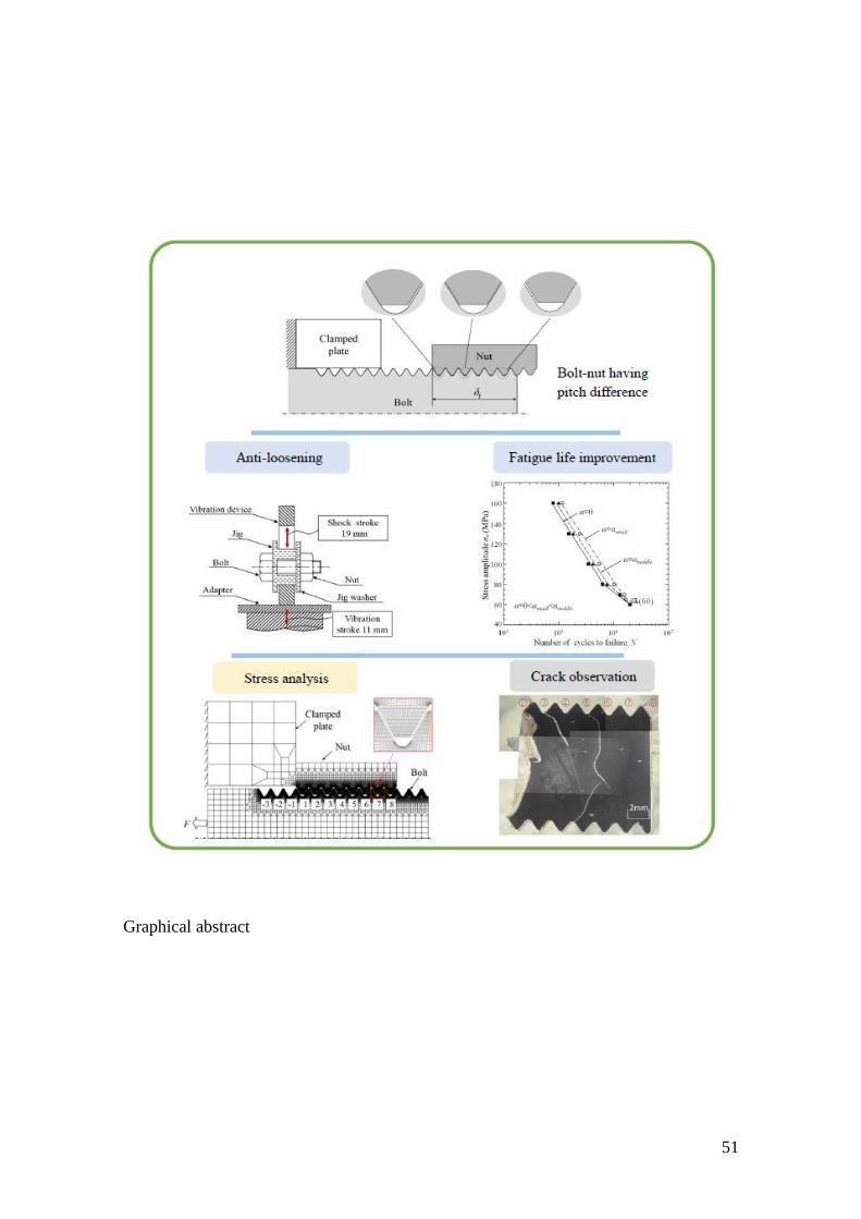
Graphical abstract

52
Highlights
Bolt-nut with various pitch difference are studied experimentally and analytically.
A suitable pitch difference can realize the anti-loosening performance.
A suitable pitch difference can extend the fatigue life to about 1.5 times.
Pitch difference affects the crack trajectories of bolt significantly.