Embed Size (px)
Citation preview
arX
iv:c
ond-
mat
/990
3172
v1 [
cond
-mat
.dis
-nn]
10
Mar
199
9
Effects of resonant tunneling in electromagnetic wave propagation through a polariton
gap∗
Lev I. Deych†, A. Yamilov‡, and A.A. Lisyansky‡† Department of Physics, Seton Hall University, South Orange, NJ 07079
‡ Department of Physics, Queens College of CUNY, Flushing, NY 11367
We consider tunneling of electromagnetic waves through a polariton band gap of a 1-D chain ofatoms. We analytically show that a defect embedded in the structure gives rise to the resonancetransmission at the frequency of a local polariton state associated with the defect. NumericalMonte-Carlo simulations are used to examine properties of the electromagnetic band arising insidethe polariton gap due to finite concentration of defects.
I. INTRODUCTION
The resonant tunneling of electromagnetic waves through different types of optical barriers is a fast developingarea of optical physics. This effect was first considered for photonic crystals,1,2 where forbidden band-gaps in theelectromagnetic spectrum form optical barriers. Macroscopic defects embedded in the photonic crystal give rise tolocal photon modes,3–7 which induce the resonant transmission of electromagnetic waves through the band-gaps.
A different type of photonic band gaps arises in polar dielectrics, where a strong resonance interaction betweenthe electromagnetic field and dipole active internal excitations of a dielectric brings about a gap between differentbranches of polaritons. Recently it was suggested that regular microscopic impurities embedded in such a dielectricgive rise to local polariton states,8–10 where a photon is coupled to an intrinsic excitation of a crystal, and both thesecomponents are localized in the vicinity of the defect.11 The main peculiarity of the local polaritons is that theirelectromagnetic component is bound by a microscopic defect whose size is many order of magnitude smaller then thewavelengths of respective photons. Another important property of these states is the absence of a threshold for theirappearance even in 3-D isotropic systems, while for all other known local states the “strength” of a defect must exceeda certain critical value before the state would split off a continous spectrum. The reason for this peculiar behavior isa strong van Hove singularity in the polariton density of states in the long wave region, caused by a negative effectivemass of the polariton-forming excitations of a crystal.
The feasibility of resonant electromagnetic tunneling induced by local polaritons, however, is not self-evident. Theidea of a microscopic defect affecting propagation of waves with macroscopic wavelength seems to be in contradictionwith common wisdom. Besides, it was found that the energy of the electromagnetic component of local polaritonsis very small compared to the energy of its crystal counterpart. The existence of the tunneling effect was firstnumerically demonstrated in Ref. 9, where a 1-D chain of dipoles interacting with a scalar field imitating transverseelectromagnetic waves was considered. It was found that a single defect embedded in such a chain results in near100% transmission at the frequency of local polaritons through a relatively short chain (50 atoms). The frequencyprofile of the transmission was found to be strongly assymetric, in contrast to the case of electron tunneling.16
In most cases (at least for a small concentration of the transmitting centers) one-dimensional models give a reliabledescription of tunneling processes, because by virtue of tunneling, a wave propagates along a chain of resonancecenters, for which a 1-D topology has the highest probability of occurrence.17 In our situation, it is also importantthat the local polariton states (transmitting centers) occur without a threshold in 3-D systems as well as in 1-Dsystems. This ensures that the transmission resonances found in Ref. 9 are not artifacts of the one-dimensional natureof the model, and justifies a further development of the model. In the present paper we pursue this development intwo interconnected directions. First, we present an exact analytical solution of the transmission problem through thechain with a single defect. This solution explains the unusual asymmetric shape of the transmission profile foundin numerical calculations9 and provides insight into the phenomenon under consideration. Second, we carry outnumerical Monte-Carlo simulation of the electromagnetic transmission through a macroscopically long chain with afinite concentration of defects, and study the development of a defect-induced electromagnetic pass band within thepolariton band-gap. The analytical solution of a single-defect model allows us to suggest a physical interpretation for
∗To be published in Phys. Rev. B, 1999
1
some of the peculiarities of the transmission found in numerical simulations. As a by-product of our numerical resultswe present a new algorithm used for the computation of the transmission. This algorithms is based upon a blendof transfer-matrix approach with ideas of the invariant-embedding method,18 and proves to be extremely stable evendeep inside the band-gap, where traditional methods would not work.
Though we consider the one-dimensional model, the results obtained are suggestive for experimental observation ofthe predicted effects. Actually the damping of the electromagnetic waves is more experimentally restrictive than thetopology of the system. We, however, discuss the effects due to damping and come to the conclusion that the effectsunder discussion can be observed in regular ionic crystals in the region of their phonon-polariton band-gaps.
The paper is organized as follows. The Introduction is followed by an analytical solution of the transmission problemin a single-impurity situation. The next section presents results of Monte-Carlo computer simulations. The algorithmused in numerical calculations is derived and discussed in the Appendix. The paper concludes with a discussion ofthe results.
II. DESCRIPTION OF THE MODEL AND ANALYTICAL SOLUTION OF A SINGLE-DEFECT
PROBLEM
1. The model
Our system consists of a chain of atoms interacting with each other and with a scalar “electromagnetic” field.Atoms are represented by their dipole moments Pn, where the index n represents the position of an atom in the chain.Dynamics of the atoms is described within the tight-binding approximation with an interaction between nearestneighbors only,
(Ω2n − ω2)Pn + Φ(Pn+1 + Pn−1) = αE(xn), (1)
where Φ is a parameter of the interaction, and Ω2n represents the site energy. Impurities in the model differ from host
atoms in this parameter only, so
Ω2n = Ω2
0cn + Ω21(1 − cn), (2)
where Ω20 is the site energy of a host atom, Ω2
1 describes an impurity, cn is a random variable taking values 1 and 0with probabilities 1 − p and p, respectively. Parameter p, therefore, sets the concentration of the impurities in oursystem. This choice of the dynamical equation corresponds to exciton-like polarization waves. Phonon-like waves canbe presented in a form that is similar to Eq. (1) with Ω2
n = Ω20 + (1− cn)(1−Mdef/Mhost)ω
2, where Mdef and Mhost
are masses of defects and host atoms, respectively.Polaritons in the system arise as collective excitations of dipoles (polarization waves) coupled to the electromagnetic
wave, E(xn), by means of a coupling parameter α. The electromagnetic subsystem is described by the followingequation of motion
ω2
c2E(x) +
d2E
dx2= −4π
ω2
c2
∑
n
Pnδ(na − x), (3)
where the right hand side is the polarization density caused by atomic dipole moments, and c is the speed of light invacuum. The coordinate x in Eq. (3) is along the chain with an interatomic distance a. Eqs. (1) and (3) present amicroscopic description of the transverse electromagnetic waves propagating along the chain in the sense that it doesnot make use of the concept of the dielectric permeability, and takes into account all modes of the field includingthose with wave numbers outside of the first Brillouin band.
This approach enables us to address several general questions. A local state is usually composed of states withall possible values of wave number k. States with large k cannot be considered within a macroscopic dielectricfunction theory, and attempts to do so lead to divergent integrals that need to be renormalized.15 In our approach,all expressions are well defined, so we can check whether a contribution from large k is important, and if the longwave approximation gives reliable results. Calculation of the integrals appearing in the 3-D theory requires detailedknowledge of the spectrum of excitations of a crystal throughout the entire Brillouin band. This makes analyticalconsideration practically unfeasible. In our 1-D model, we can carry out the calculations analytically (in a single-impurity case) and examine the influence of different factors (and approximations) upon the frequency of a local stateand the transmission coefficient. Using caution, the results obtained can be used to assess approximations in 3-Dcases.
2
2. A single impurity problem
The equation for the frequency of the local polariton state in the 1-D chain has the form similar to that derived inRef. [ 8]
1 = ∆Ω2G(0), (4)
where, however, the expression for the polariton Green’s function G(n−n0) responsible for the mechanical excitationof the system can be obtained in the explicit form
G(n − n0) =∑
k
cos(ak) − cos(aωc
)
[ω2 − Ω20 − 2Φ cos (ka)]
[
cos(ak) − cos(aωc
)]
− 2παω
csin(
aω
c)
exp [ik (n − n0) a] . (5)
If one neglects the term responsible for the coupling to the electromagnetic field, the Green’s function G(n − n0) isreduced to that of the pure atomic system. This fact reflects the nature of the defect in our model: it only disturbsthe mechanical (not related to the interaction with the field) properties of the system. A solution of Eq. (4) canbe real-valued only if it falls into the gap between the upper and lower polariton branches. This gap exists if theparameter Φ in the dispersion equation of the polariton wave is positive, and the effective mass of the excitations inthe long wave limit is, therefore, negative.
The diagonal element, G(0), of Green’s function (5) can be calculated exactly. The dispersion equation (4) thantakes the following form:
1 = ∆Ω2 1
2ΦD(ω)
[
cos(aωc
) − Q2(ω)√
Q22(ω) − 1
− cos(aωc
) − Q1(ω)√
Q21(ω) − 1
]
, (6)
where Q1,2(ω),
Q1,2(ω) =1
2
[
cos(aω
c) +
ω2 − Ω20
2Φ
]
± 1
2D(ω), (7)
D(ω) =
√
[
cos(aω
c) − ω2 − Ω2
0
2Φ
]2
− 4παω
Φcsin(
aω
c) (8)
give the poles of the integrand in Eq. (5). The bottom of the polariton gap is determined by the condition D(ω) = 0,yielding in the long wave limit, aω/c ≪ 1, for the corresponding frequency, ωl,
ω2l ≃ Ω2
0 − 2Ω20d
√Φa
c, (9)
where we introduce parameters d2 = 4πα/a, Ω20 = Ω2
0 + 2Φ, and take into account that the band width of the
polarization waves, Φ, obeys the inequality√
Φa/c ≪ 1. The last term in this expression is the correction to thebottom of the polariton gap due to the interaction with the transverse electromagnetic field. Usually this correction issmall, but it has an important theoretical, and, in the case of strong enough spatial dispersion and oscillator strength,practical significance.8 Because of this correction the polariton gap starts at a frequency, when the determinant D(ω)becomes imaginary, but functions Q1,2(ω) are still less than 1. This leads to the divergence of the right-hand side ofEq. (6) as ω approaches ωl, and, hence, to the absence of a threshold for the solution of this equation. This divergenceis not a 1-D effect since the same behavior is also found in 3-D isotropic model.8,10 An asymptotic form for Eq. (6)when ω −→ ωl in the 1-D case reads
√
ω2 − ω2l ∼ ∆Ω2
√Φ
, (10)
and differs from the 3-D case by the factor of(
dωla)/(c√
Φ)
. The upper boundary of the gap, ωup, is determined by
the condition Q1(ω) = 0, leading to
ω2up = Ω2
0 + d2, (11)
3
Eq. (6) also has a singularity as ω −→ ωup, but this singularity is exclusively caused by the 1-D nature of the system.We will discuss local states that are not too close to the upper boundary in order to avoid manifestations of purely1-D effects.
For frequencies deeper inside the gap, Eq. (4) can be simplified in the approximation of small spatial dispersion,√Φa/c ≪ 1, to yield
ω2 = Ω21 − ∆Ω2
[
1 −√
ω2 − Ω20
ω2 − Ω20 + 4Φ
]
− d2 ωa
2c
∆Ω2
√
(
ω2 − Ω20
)(
Ω20 + d2 − ω2
)
, (12)
where Ω21 = Ω2
1 + 2Φ is a fundamental (k = 0) frequency of a chain composed of impurity atoms only. Two otherterms in Eq. (12) present corrections to this frequency due to the spatial dispersion and the interaction with theelectromagnetic field respectively. One can see that both corrections have the same sign and shift the local frequencyinto the region between Ω2
0 and Ω21. As we see below, this fact is significant for the transport properties of the chain.
Transmission through the system can be considered in the framework of the transfer matrix approach. This methodwas adapted for the particular case of the system under consideration in Ref. 9. The state of the system is describedby the vector vn, with components Pn, Pn+1, En, E′
n/kω), which obeys to the following difference equation
vn+1 = Tnvn. (13)
The transfer matrix Tn describes the propagation of the vector between adjacent sites:
Tn =
0 1 0 0
−1 −Ω2n − ω2
Φ
α
Φcos ka
α
Φsinka
0 0 cos ka sin ka0 −4πk − sinka cos ka
. (14)
Analytical calculation of the transmission coefficient in the situation considered is not feasible even in the case of asingle impurity because the algebra is too cumbersome. The problem, however, can be simplified considerably if oneneglects the spatial dispersion of the polarization waves. In this case the T -matrix can be reduced to a 2 × 2 matrixof the following form
τn =
(
cos ka sin ka− sinka + βn cos ka cos ka + βn sin ka
)
, (15)
where the parameter βn
βn =4παω
c (ω2 − Ω2n)
, (16)
represents the polarizability of the n-th atom due to its vibrational motion. In this case the complex transmission
coefficient, t, can be easily expressed in terms of the elements of the resulting transfer matrix, T (N) =∏N
1 τn,
t =2
(
T(N)11 + T
(N)22
)
− i(
T(N)12 − T
(N)21
)e−ikL. (17)
The problem is, therefore, reduced to the calculation of T (N). In the case of a single impurity, the product of thetransfer matrices, τ , can be presented in the following form
T (N) = τN−n0 × τdef × τn0−1, (18)
where the matrix τdef describes the impurity atom with Ωn = Ω1. The matrix product in Eq. (18) is convenientlycalculated in the basis, where the matrix τ is diagonal. After some cumbersome algebra, one obtains for the complextransmission coefficient:
t =2eikL exp (−κL)
[
1 − i√R
(2 − β cot ka)]
[(1 + ε)] + 2i exp (−κL) Γ cosh [κa(N − 2n0 + 1]. (19)
4
where R = β2+4β cot(ak)−4, Γ = εβ/(sin(ka)√
R), κ is the imaginary wave number of the evanescent electromagnetic
excitations, which determines the inverse localization length of the local state, and ε = (βdef − β) /2√
R. The lastparameter describes the difference between host atoms and the impurity, and is equal to
ε =2πα
c√
Rω
(
Ω21 − Ω2
0
)
(ω2 − Ω20) (ω2 − Ω2
1). (20)
We have also neglected here a contribution from the second eigenvalue of the transfer matrix, which is proportionalto exp(−2κL), and is exponentially small for sufficiently long chains. For ε = 0, Eq. (19) gives the transmissioncoefficient, t0, of the pure system,
t0 =2eikL exp (−κL)
1 − i√R
(2 − β cotka), (21)
exhibiting a regular exponential decay. At the lower boundary of the polariton gap, Ω0, parameters β and κ diverge,leading to vanishing transmission at the gap edge regardless the length of the chain. It is instructive to rewrite Eq.(19) in terms of t0:
t =t0
(1 + ε) + i exp (−ikL)Γt0 cosh [κa(N − 2n0 + 1](22)
This expression describes the resonance tunneling of the electromagnetic waves through the chain with the defect.The resonance occurs when
1 + ε = 0, (23)
the transmission in this case becomes independent of the system size. Substituting the definition of the parameterε given by Eq. (20) into Eq. (23), one arrives at an equation identical to Eq. (12) for the frequency of the localpolariton state with the parameter of the spatial dispersion, Φ, being set to zero. The transmission takes a maximumvalue when the defect is placed in the middle of the chain, N − 2n0 + 1 = 0, and in this case
|tmax|2 =1
Γ2≤ 1. (24)
The width of the resonance is proportional to Γt0 and decreases exponentially with an increase of the system’s size.In the long wave limit, ak ≪ 1, Eq. (24) can be rewritten in the following form
|tmax|2 = 1 −(
1 − 2ω2
r − Ω20
d2
)
, (25)
where ωr is the resonance frequency satisfying Eq. (23). It is interesting to note that the transmission coefficientbecomes exactly equal to one if the resonance frequency happens to occur exactly in the center of the polariton gap.This fact has a simple physical meaning. For ω2
r = Ω20 + d2/2 the inverse localization length κ becomes equal to the
wave number ωr/c of the incoming radiation. Owing to this fact, the field and its derivative inside the chain exactlymatch the field and the derivative of the incoming field as though the optical properties of the chain are identical tothose in vacuum. Consequently, the field propagates through the chain without reflection.
Having solved the transmission problem we can find the magnitude of the field inside the chain in terms of theincident amplitude Ein at the resonance frequency. Spatial distribution of the field in the local polariton state canbe found to have the form E = Ed exp (−|n − n0|κa). Matching this expression with the outcoming field equal toEint exp(ikL) one has for the field amplitude at the defect atom, Ed,
Ed = Eint exp(−ikL) exp [(N − n0)κa] . (26)
For |t| being of the order of one in the resonance this expression describes the drastic exponential enhancement of theincident amplitude at the defect side due to the effect of the resonance tunneling.
Equations (22) and (24) demonstrate that the resonance tunneling via local polariton states is remarkably differentfrom other types of resonance tunneling phenomena, such as electron tunneling via an impurity state,16 or througha double barrier. The most important fact is that the frequency profile of the resonance does not have the typicalsymmetric Laurentian shape. At ω = Ω1 the parameter ε diverges causing the transmission to vanish. At the same
5
time the resonance frequency ωr is very close to Ω1 as it follows from Eq. (12). This results in strongly asymmetricfrequency dependence of the transmission, which is skewed toward lower frequencies.
The transmission vanishes precisely at two frequencies: at the low frequency band edge Ω0 and at the fre-quency Ω1 associated with the vibrational motion of the defect atom. At the same time, the behavior of thetransmission coefficient in the vicinities of these two frequencies is essentially different: at the band edge it is
(ω2 − Ω20)
2 exp(
−1/√
ω2 − Ω20
)
while at the defect frequency the transmission goes to zero as (ω2 − Ω21)
2. These
facts can be used to predict several effects that would occur with the increase of the concentration of the defects.First, one can note that with the increase of concentration of the impurities frequency Ω1 becomes eventually theboundary of the new polariton gap when all the original host atoms will be replaced by the defects atoms. One canconclude then that the zero of the transmission at Ω1 instead of being washed out by the disorder, would actuallybecome more singular. More exactly one should expect that the frequency dependence of the transmission in thevicinity of Ω1 will exhibit a crossover from the simple power decrease to the behavior with exponential singularityassociated with the band edge. Second, if one takes into account such factors as spatial dispersion or damping, whichprevent transmission from exact vanishing, one should expect that the above mentioned crossover to the more singularbehavior would manifest itself in the form of substantial decrease of the transmission in the vicinity of Ω1 with anincrease of the concentration. Numerical calculations discussed in the next section of the paper show that this effectdoes take place even at rather small concentration of the defects.
Resonance tunneling is very sensitive to the presence of relaxation, which phenomenologically can be accounted forby adding 2iγω to the denominator of the polarizability β, where γ is an effective relaxation parameter. This willmake the parameter ǫ complex valued, leading to two important consequences. First, the resonance condition becomesRe(ε) = −1, and it can be fulfilled only if the relaxation is small enough. Second, the imaginary part of ε will preventthe exponential factor t0 in Eq. (22) from canceling out at the resonance. This restricts the length of the system inwhich the resonance can occur and limit the enhancement of the field at the defect. These restrictions though are notspecific for the system under consideration and affect experimental manifestation of any type of resonant tunnelingphenomenon.
Since we only concern with a frequency region in the vicinity of Ω1, real, ε1, and imaginary, ε2, parts of ε can beapproximately found as
ε1 ≃ d2 Ω1a
2c
√
∆Ω2
d2 − ∆Ω2
ω2 − Ω21
(ω2 − Ω21)
2+ 4γ2ω2
, (27)
ε2 ≃ 2γω
ω2 − Ω21
ε1. (28)
It follows from Eq. (27) that the resonance occurs only if (4γc)/(ad2) < 1. This inequality has a simple physicalmeaning: it ensures that the distance between the resonance frequency, ωr, and Ω1, where the transmission goesto zero, is greater than the relaxation parameter, γ. This is a rather strict condition that can only be satisfied forhigh frequency oscillations with large oscillator strength in crystals with large interatomic spacing, a. The spatialdispersion, however, makes conditions for the resonant tunneling much less restrictive. In order to estimate the effectof the dissipation in the presence of the spatial dispersion one can rely upon Eq. (22) assuming that the dispersiononly modifies the parameter ε, but does not effect the general expression for the transmission. This assumption isjustified by the numerical results of Ref. 9 and the present paper, which show that the transmission properties inthe presence of the spatial dispersion do not differ significantly from the analytical calculations performed for thechain of noninteracting dipoles. According to Eq. (12), the inter-atomic interaction moves the resonance frequencyfurther away from Ω1 undermining the influence of the damping and leading to a weaker inequality: (γΩ1)/Φ < 1.This condition can be easily fulfilled, even for phonons with a relatively small negative spatial dispersion. For theimaginary part ε2 at the resonance one can obtain from Eq. (28) the following estimate
ε2 ∼ min[(4γc)/(ad2), (γΩ1)/Φ]. (29)
The requirement that ε2 be much smaller than t0 leads to the following restriction for the length of the systemL ≪ (1/κ) | ln[ε2] |, with ε2 given above. The maximum value of the field at the defect site attainable for the defectlocated in the center of the chain is then found as |Ed| ∼ |Ein||t|/
√ε2.
6
III. ONE-DIMENSIONAL DIPOLE CHAIN WITH FINITE CONCENTRATION OF IMPURITIES
In this section we present results of numerical Monte-Carlo simulations of the transport properties of the systemunder consideration in the case of randomly distributed identical defects. If spatial dispersion is taken into accountthe regular Maxwell boundary conditions must be complemented by additional boundary conditions regulating thebehavior of polarization P at the ends of the chain. In our previous paper9 we calculated the transmission for two typesof boundary conditions: P0 = PN = 0, which corresponds to the fixed ends of the chain, and P0 = P1, PN−1 = PN ,which corresponds to the relaxed ends. We reported in Ref. 9 that the transmission is very sensitive to the boundaryconditions with fixed ends being much more favorable for the resonance. Our present numerical results obtainedwith an improved numerical procedure and the analytical calculations do not confirm this dependence of the resonanttunneling upon the boundary conditions. In the case of a single impurity we find that for both types of the boundaryconditions the transmission demonstrates sharp resonance similar to that found in Ref. 9 for fixed ends. Similarly, fora finite concentration of impurities we did not find any considerable differences in the transmission for both types ofboundary conditions. We conclude that the actual form of the boundary conditions is not significant for the resonanttunneling.
The transfer matrix, Eq. (13), along with the definition of the transfer matrix, Eq. (14), and the boundaryconditions chosen in the form of fixed terminal points, provides a basis for our computations. However, it turns outthat straightforward use of Eq. (13) in the gap region is not possible because of underflow errors arising when onepair of eigenvalues of the transfer matrix becomes exponentially greater than the second one. In order to overcomethis problem we develop a new computational approach based upon the blend of the transfer-matrix method with theinvariant embedding ideas. The central element of the method is a 4× 4 matrix S(N) that depends upon the systemsize N . The complex transmission coefficient, t, is expressed in terms of the elements of this matrix as
t = 2 exp(−ikL)(S11 + S12). (30)
The matrix S(N) is determined by the following nonlinear recursion
S(N + 1) = TN × Ξ(N) × S(N), (31)
where matrix Ξ(N) is given by
Ξ(N) = I − S(N) × H × [I − T (N)]−1. (32)
The initial condition to Eq. (31) is given by
S(0) = (G + H)−1, (33)
where matrices G and H are specified by the boundary conditions. The derivation of the Eqs. (30)-(33) and moredetailed discussion of the method is given in the Appendix to the paper. The test of the algorithm based uponrecursion formula (31) proves the method to provide accurate results for transmission coefficients as small as 10−15.
In our simulations we fix the concentration of the defects and randomly distribute them among the host atoms.The total number of atoms in the chain is also fixed; the results presented below are obtained for a chain consisting of1000 atoms. For the chosen defect frequency, Ω1 ≃ 1.354Ω0, the localization length of the local polariton state, lind,isapproximately equal to 150 interatomic distances. The transmission coefficient is found to be extremely sensitive toa particular arrangements of defects in a realization exhibiting strong fluctuations from one realization to another.Therefore, in order to reveal the general features of the transmission independent of particular positions of defects, weaverage the transmission over 1000 different realizations. We have also calculated the averaged Lyapunov exponent(the inverse localization length, lchain, characterizing transport through the entire chain) to verify that the averagedtransmission reveals a reliable information about the transport properties of the system.
The results of the computations are presented in the figures below. Figs. 1-3 show an evolution of the transmissionwith the increase of the concentration of the impurities. In Fig. 1 one can see the change of the transport propertiesat small concentrations up to 1%. The curve labeled (1) shows, basically, the single impurity behavior averaged overrandom positions of the defect. With an increase of the concentration there is a greater probability for two (or more)defects to form a cluster resulting in splitting a single resonance frequency in two or more frequencies. The doublepeak structure of the curves (2) and (3) reflects these cluster effects. With the further increase of the concentration theclusters’ sizes grow on average leading to multiple resonances with distances between adjacent resonance frequenciesbeing too small to be distinguished. Curve (5) in Fig. 1 reflects this transformation, which marks a transition betweenindividual tunneling resonances and the defect induced band. The concentrations in this transition region is suchthat an average distance between the defects is equal to the localization length of the individual local states, lind.
7
The collective localization length at the frequency of the transmission peak, lmaxchain, becomes equal to the length of the
chain at approximately the same concentration that allows to suggest a simple relationships between the two lengths:lmaxchain = clind, where c stands for the concentration. The numerical results presented in Fig. 4 clearly demonstrate thislinear concentration dependence of lmax
chain at small concentrations. For larger concentrations one can see from Figs. 2and 3 that the peak of the transmission coefficient developes into a broad structure. This marks further developmentof the defect pass band. Curves in Fig. 2 show the transmission coefficient at intermediate concentrations, wherelocalization length, lchain, is bigger than the length of the system only in a small frequency region around the maximumof the transmission, and Fig. 3 presents well developed pass band with multipeak structure resulting from geometricalresonances at the boundaries of the system.
This figures reveal an important feature of the defect polariton band: its right edge does not move with increase ofthe concentration. The frequency of this boundary is exactly equal to the defect frequency, Ω1, (which is normalizedby Ω0 in the figures), and the entire band is developing to the left of Ω1 in complete agreement with the argumentsbased upon analytical solution of the single-impurity problem. Moreover, the magnitude of the transmission in thevicinity of Ω1decreases with increase of the concentration also in agreement with our remarks at the end of the previoussection. Fig. 5 presents the inverse localization length, lchain, normalized by the length of the chain for three differentconcentrations. It can be seen that l−1
chain( Ω1) significantly grows with increase of the concentration, reaching thevalue of approximately 17/L at the concentration as small as 3%. Such a small localization length corresponds to thetransmission of the order of magnitude of 10−17, which is practically zero in our computation. Further increase of theconcentration does not change the minimum localization length. These results present an interesting example of thedefects building up a boundary of the new forbidden gap.
From this figure it is also seen the development of the pass band to the left of Ω1 presented above in Figs. 1-3, butat a larger scale. We can not distinguish here the details of the frequency dependence, but the transition from thesingle resonance behavior to the pass band, marked by the significant flattening of the curve, is clear.
The last Fig. 6 presents the concentration dependence of the semiwidth, δω, of the defect band. The semiwidthis defined as the difference between frequency of the maximum transmission and the right edge of the band. Onecan see that all the point form a smooth line with no indication of a change of the dependence with the transitionbetween different transport regimes. Attempts to fit this curve showed that it is excellently fitted by the power lawδω ∝ cνwith ν ≃ 0.8 in all studied concentration range. The reason for this behavior and why it is insensitive to thechange of the character of the transport requires further study.
IV. CONCLUSION
In this paper, we considered one-dimensional resonance tunneling of scalar “electromagnetic waves” through anoptical barrier caused by a polariton gap. The tunneling is mediated by local polariton states arising due to defectatoms embedded in an otherwise ideal periodic chain. We also numerically studied how a defect-induced propagatingband emerges from these resonances when the concentration of defects increases.
It is important to emphasize the difference between the situation considered in our paper and other types oftunneling phenomena discussed in the literature. The tunneling of electromagnetic waves through photonic crystalsand electron tunneling, despite all the difference between these phenomena, share one common feature. In both cases,the resonance occurs due to defects that have dimensions comparable with wavelengths of the respective excitations(electrons interact with atomic impurities, and long wave electromagnetic waves interact with macroscopic distortionsof the photonic crystals). In our case the wavelength of the propagating excitations is many orders of magnitudegreater than dimensions of the atomic defects responsible for the resonance. The physical reason for such an unusualbehavior lies in the nature of local polaritons. These states are formed owing to the presence of internal polariton-forming excitations. The spatial extent of these states is much larger than the geometrical dimensions of atomicdefects and is comparable to the wavelength of the incident radiation.
We presented an exact analytical solution of the tunneling of electromagnetic waves through a chain of noninteractingatoms with a single defect. This solution provides insight into the nature of the phenomenon under considerarionand allows one to obtain an explicit expression for the magnitude of the electromagnetic field at the defect site. Theexpression derived demonstrates that the field is strongly enhanced at the resonance with its magnitude growingexponentially with an increase of the length of the system. This effect is an electromagnetic analogue of the chargeaccumulation in the case of electron tunneling, where it is known to cause interesting nonlinear phenomena.19–23
An analytical solution of the single-defect problem allowed us to make predictions regarding the transport propertiesof the system with multiple randomly located defects. The most interesting of these is that the dynamical frequencyof the defects, Ω1, sets a high frequency boundary for the defect induced pass band, which does not move withincreasing concentration of defects. Numerical Monte-Carlo simulations confirmed this assumption and showed that
8
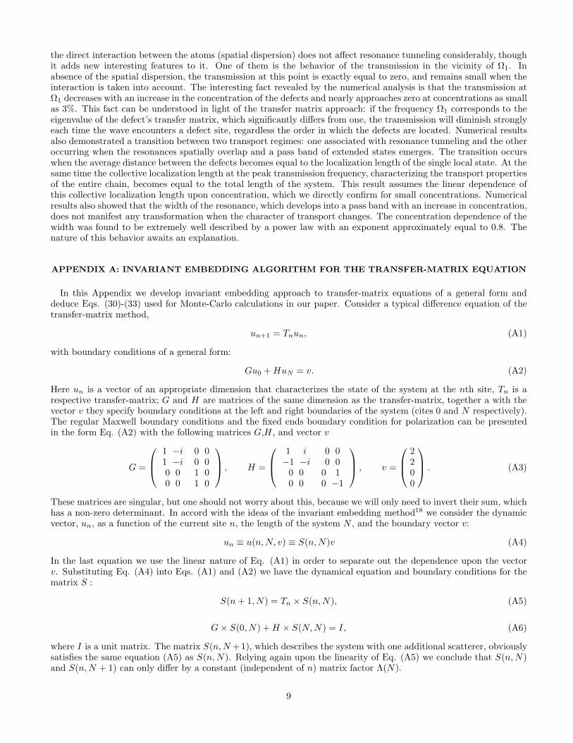
the direct interaction between the atoms (spatial dispersion) does not affect resonance tunneling considerably, thoughit adds new interesting features to it. One of them is the behavior of the transmission in the vicinity of Ω1. Inabsence of the spatial dispersion, the transmission at this point is exactly equal to zero, and remains small when theinteraction is taken into account. The interesting fact revealed by the numerical analysis is that the transmission atΩ1 decreases with an increase in the concentration of the defects and nearly approaches zero at concentrations as smallas 3%. This fact can be understood in light of the transfer matrix approach: if the frequency Ω1 corresponds to theeigenvalue of the defect’s transfer matrix, which significantly differs from one, the transmission will diminish stronglyeach time the wave encounters a defect site, regardless the order in which the defects are located. Numerical resultsalso demonstrated a transition between two transport regimes: one associated with resonance tunneling and the otheroccurring when the resonances spatially overlap and a pass band of extended states emerges. The transition occurswhen the average distance between the defects becomes equal to the localization length of the single local state. At thesame time the collective localization length at the peak transmission frequency, characterizing the transport propertiesof the entire chain, becomes equal to the total length of the system. This result assumes the linear dependence ofthis collective localization length upon concentration, which we directly confirm for small concentrations. Numericalresults also showed that the width of the resonance, which develops into a pass band with an increase in concentration,does not manifest any transformation when the character of transport changes. The concentration dependence of thewidth was found to be extremely well described by a power law with an exponent approximately equal to 0.8. Thenature of this behavior awaits an explanation.
APPENDIX A: INVARIANT EMBEDDING ALGORITHM FOR THE TRANSFER-MATRIX EQUATION
In this Appendix we develop invariant embedding approach to transfer-matrix equations of a general form anddeduce Eqs. (30)-(33) used for Monte-Carlo calculations in our paper. Consider a typical difference equation of thetransfer-matrix method,
un+1 = Tnun, (A1)
with boundary conditions of a general form:
Gu0 + HuN = v. (A2)
Here un is a vector of an appropriate dimension that characterizes the state of the system at the nth site, Tn is arespective transfer-matrix; G and H are matrices of the same dimension as the transfer-matrix, together a with thevector v they specify boundary conditions at the left and right boundaries of the system (cites 0 and N respectively).The regular Maxwell boundary conditions and the fixed ends boundary condition for polarization can be presentedin the form Eq. (A2) with the following matrices G,H , and vector v
G =
1 −i1 −i
0 00 0
0 00 0
1 01 0
, H =
1 i−1 −i
0 00 0
0 00 0
0 10 −1
, v =
2200
. (A3)
These matrices are singular, but one should not worry about this, because we will only need to invert their sum, whichhas a non-zero determinant. In accord with the ideas of the invariant embedding method18 we consider the dynamicvector, un, as a function of the current site n, the length of the system N , and the boundary vector v:
un ≡ u(n, N, v) ≡ S(n, N)v (A4)
In the last equation we use the linear nature of Eq. (A1) in order to separate out the dependence upon the vectorv. Substituting Eq. (A4) into Eqs. (A1) and (A2) we have the dynamical equation and boundary conditions for thematrix S :
S(n + 1, N) = Tn × S(n, N), (A5)
G × S(0, N) + H × S(N, N) = I, (A6)
where I is a unit matrix. The matrix S(n, N +1), which describes the system with one additional scatterer, obviouslysatisfies the same equation (A5) as S(n, N). Relying again upon the linearity of Eq. (A5) we conclude that S(n, N)and S(n, N + 1) can only differ by a constant (independent of n) matrix factor Λ(N).
9
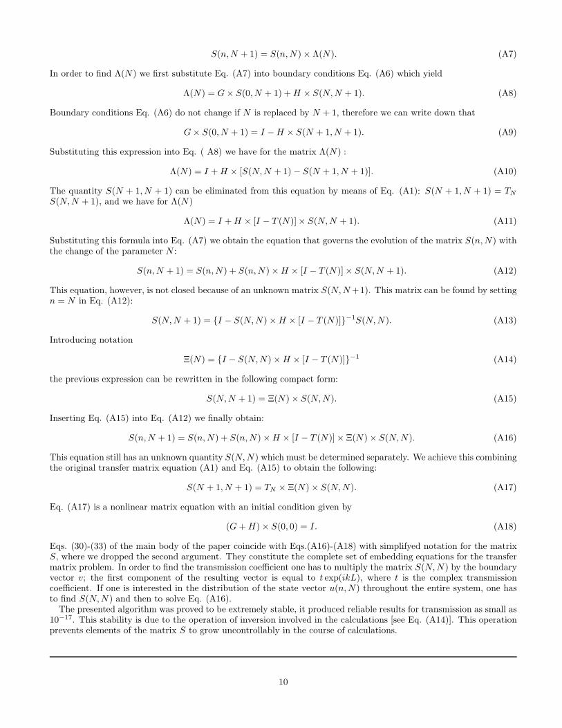
S(n, N + 1) = S(n, N) × Λ(N). (A7)
In order to find Λ(N) we first substitute Eq. (A7) into boundary conditions Eq. (A6) which yield
Λ(N) = G × S(0, N + 1) + H × S(N, N + 1). (A8)
Boundary conditions Eq. (A6) do not change if N is replaced by N + 1, therefore we can write down that
G × S(0, N + 1) = I − H × S(N + 1, N + 1). (A9)
Substituting this expression into Eq. ( A8) we have for the matrix Λ(N) :
Λ(N) = I + H × [S(N, N + 1) − S(N + 1, N + 1)]. (A10)
The quantity S(N + 1, N + 1) can be eliminated from this equation by means of Eq. (A1): S(N + 1, N + 1) = TN
S(N, N + 1), and we have for Λ(N)
Λ(N) = I + H × [I − T (N)]× S(N, N + 1). (A11)
Substituting this formula into Eq. (A7) we obtain the equation that governs the evolution of the matrix S(n, N) withthe change of the parameter N :
S(n, N + 1) = S(n, N) + S(n, N) × H × [I − T (N)] × S(N, N + 1). (A12)
This equation, however, is not closed because of an unknown matrix S(N, N +1). This matrix can be found by settingn = N in Eq. (A12):
S(N, N + 1) = I − S(N, N) × H × [I − T (N)]−1S(N, N). (A13)
Introducing notation
Ξ(N) = I − S(N, N) × H × [I − T (N)]−1 (A14)
the previous expression can be rewritten in the following compact form:
S(N, N + 1) = Ξ(N) × S(N, N). (A15)
Inserting Eq. (A15) into Eq. (A12) we finally obtain:
S(n, N + 1) = S(n, N) + S(n, N) × H × [I − T (N)] × Ξ(N) × S(N, N). (A16)
This equation still has an unknown quantity S(N, N) which must be determined separately. We achieve this combiningthe original transfer matrix equation (A1) and Eq. (A15) to obtain the following:
S(N + 1, N + 1) = TN × Ξ(N) × S(N, N). (A17)
Eq. (A17) is a nonlinear matrix equation with an initial condition given by
(G + H) × S(0, 0) = I. (A18)
Eqs. (30)-(33) of the main body of the paper coincide with Eqs.(A16)-(A18) with simplifyed notation for the matrixS, where we dropped the second argument. They constitute the complete set of embedding equations for the transfermatrix problem. In order to find the transmission coefficient one has to multiply the matrix S(N, N) by the boundaryvector v; the first component of the resulting vector is equal to t exp(ikL), where t is the complex transmissioncoefficient. If one is interested in the distribution of the state vector u(n, N) throughout the entire system, one hasto find S(N, N) and then to solve Eq. (A16).
The presented algorithm was proved to be extremely stable, it produced reliable results for transmission as small as10−17. This stability is due to the operation of inversion involved in the calculations [see Eq. (A14)]. This operationprevents elements of the matrix S to grow uncontrollably in the course of calculations.
10
1 E. Yablonovitch, T.J. Gmitter, R.D. Meade, A.M. Rappe, K.D. Brommer, and J.D. Joannopoulos. Phys. Rev. Lett. 67 3380(1991).
2 J.D. Joannopoulos, R.D. Meade, J.N. Winn. Photonic Crystals: Molding the Flow of Light (Princeton Univ. Press, 1995).3 E. Yablonovitch, Phys. Rev. Lett. 58, 2059 (1987).4 R.D. Meade, K.D. Brommer, A.M. Rappe, and J.D. Joannopoulos, Phys. Rev. B 44 13772 (1991).5 D.R. Smith, R. Dalichaouch, N. Kroll, S. Schultz, S.L. McCall and P.M. Platzman, J. Opt. Soc. Am. B 10, 314 (1993).6 A. Figotin and A. Klein, J. Stat. Phys. 86, 165 (1997).7 K. Sakoda and H. Shiroma, Phys. Rev. B 56, 4830 (1997).8 L.I. Deych and A.A. Lisyansky, Bull. Amer. Phys. Soc. 42, 203 (1997); Phys. Lett. A, 240, 329 (1998).9 L.I. Deych and A.A. Lisyansky, Phys. Lett. A, 243, 156 (1998).
10 V.S. Podolsky, L.I. Deych, and A.A. Lisyansky, Phys. Rev. B, 57, 5168 (1998).11 There is another type of local photon and polariton states, which must be distinguished from those discussed in the paper.
These are so called photon-atom12–14 and polariton-atom15 bound states that arise in both photonic and polariton band-gapsdue to optically active atom impurities.
12 S. John and T. Quang, Phys. Rev. A 50, 1764 (1994).13 S. John and J. Wang, Phys. Rev. Lett. 64, 2418 (1990); Phys. Rev. B 43, 12772 (1991).14 S. John and T. Quang, Phys. Rev. A, 52, 4083 (1995).15 V.I. Rupasov and M. Singh, Phys. Rev. A, 54, 3614 (1996); Phys. Rev. A 56, 898 (1997).16 A.V. Chaplik and M.V. Entin, Zh. Eksp. & Teor. Fiz. 67, 208 (1974) [Sov. Phys.- JETP 40]17 I.M. Lifshitz and V. Ya Kirpichenkov, Zh. Eksp. & Teor. Fiz. 77, 989 (1979) [Sov. Phys.- JETP 50].18 R. Bellman and G. Wing, An introduction to invariant embedding (Wiley, New York, 1976).19 J.C. Penley, Phys. Rev. 128, 596 (1962).20 B. Ricco and M.Ya. Azbel, Phys. Rev. B 29, 1970 (1984).21 V.J. Goldman, D.C. Tsui, and J.E. Cunningham, Phys. Rev. Lett. 58, 1256 (1987).22 V.J. Goldman, D.C. Tsui, and J.E. Cunningham, Phys. Rev. B. 35, 9387 (1987);23 A. Zaslavsky, V.J. Goldman, D.C. Tsui, and J.E. Cunningham, Appl. Phys. Lett. 53, 1408 (1988).
11

Figure Captions
Fig. 1. Frequency dependence of the averaged transmission coefficient for small concentrations of the defects. Thefrequency is normalized by the fundamental (k = 0) frequency of the pure chain, Ω0. The low-frequency boundary ofthe polariton gap is at ω ≈ 1.3 and is not shown here.Fig. 2. The same as in Fig. 1 but for intermediate concentrations.Fig. 3. The same as in Fig. 1 but for large concentrations.Fig. 4. Concentration dependence of the collective localization length, lchain, normalized by the system’s size L.Fig. 5. Frequency dependence of the Lyapunov exponent of the entire chain for several concentrations in the frequencyregion of the defect band.Fig. 6. Concentration dependence of the semiwidth of the defect band. The solid line represents fit with powerfunction cν , where ν ≈ 0.8.
12


