Embed Size (px)
Citation preview
Module 9
Non conventional Machining
Version 2 ME, IIT Kharagpur
Lesson 38
Electro Chemical Machining
Version 2 ME, IIT Kharagpur
Instructional Objectives
(i) Identify electro-chemical machining (ECM) as a particular type of
non-tradition processes (ii) Describe the basic working principle of ECM process (iii) Draw schematically the basics of ECM (iv) Draw the tool potential drop (v) Describe material removal mechanism in ECM (vi) Identify the process parameters in ECM (vii) Develop models for material removal rate in ECM (viii) Analyse the dynamics of ECM process (ix) Identify different modules of ECM equipment (x) List four application of ECM (xi) Draw schematics of four such ECM applications
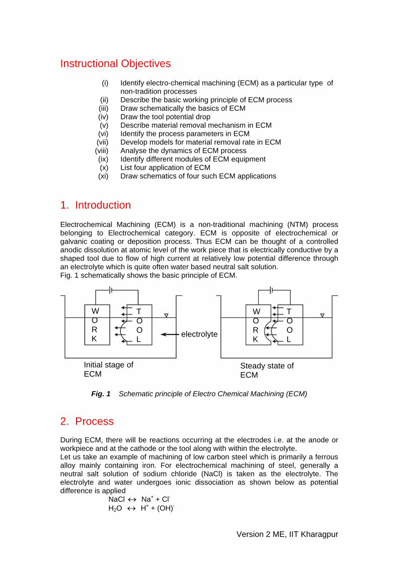
1. Introduction Electrochemical Machining (ECM) is a non-traditional machining (NTM) process belonging to Electrochemical category. ECM is opposite of electrochemical or galvanic coating or deposition process. Thus ECM can be thought of a controlled anodic dissolution at atomic level of the work piece that is electrically conductive by a shaped tool due to flow of high current at relatively low potential difference through an electrolyte which is quite often water based neutral salt solution. Fig. 1 schematically shows the basic principle of ECM. In ECM, the workpiece is connected to the positive terminal of a low voltage high current DC generator or power source. The tool is shaped and shape of the tool is transferred to the workpiece. The tool is connected to the negative terminal. Machining takes place due to anodic dissolution at atomic level of the work material due to electrochemical reaction. A gap between the tool and the workpiece is required to be maintained to proceed with steady state machining.
W O R K
T O O L
WO R K
T O O L electrolyte
Initial stage of ECM
Steady state of ECM
Fig. 1 Schematic principle of Electro Chemical Machining (ECM)
2. Process During ECM, there will be reactions occurring at the electrodes i.e. at the anode or workpiece and at the cathode or the tool along with within the electrolyte. Let us take an example of machining of low carbon steel which is primarily a ferrous alloy mainly containing iron. For electrochemical machining of steel, generally a neutral salt solution of sodium chloride (NaCl) is taken as the electrolyte. The electrolyte and water undergoes ionic dissociation as shown below as potential difference is applied NaCl ↔ Na+ + Cl- H2O H↔ + + (OH)-
Version 2 ME, IIT Kharagpur
As the potential difference is applied between the work piece (anode) and the tool (cathode), the positive ions move towards the tool and negative ions move towards the workpiece. Thus the hydrogen ions will take away electrons from the cathode (tool) and from hydrogen gas as: 2H+ + 2e- = H2↑ at cathode Similarly, the iron atoms will come out of the anode (work piece) as: Fe = Fe+ + + 2e-
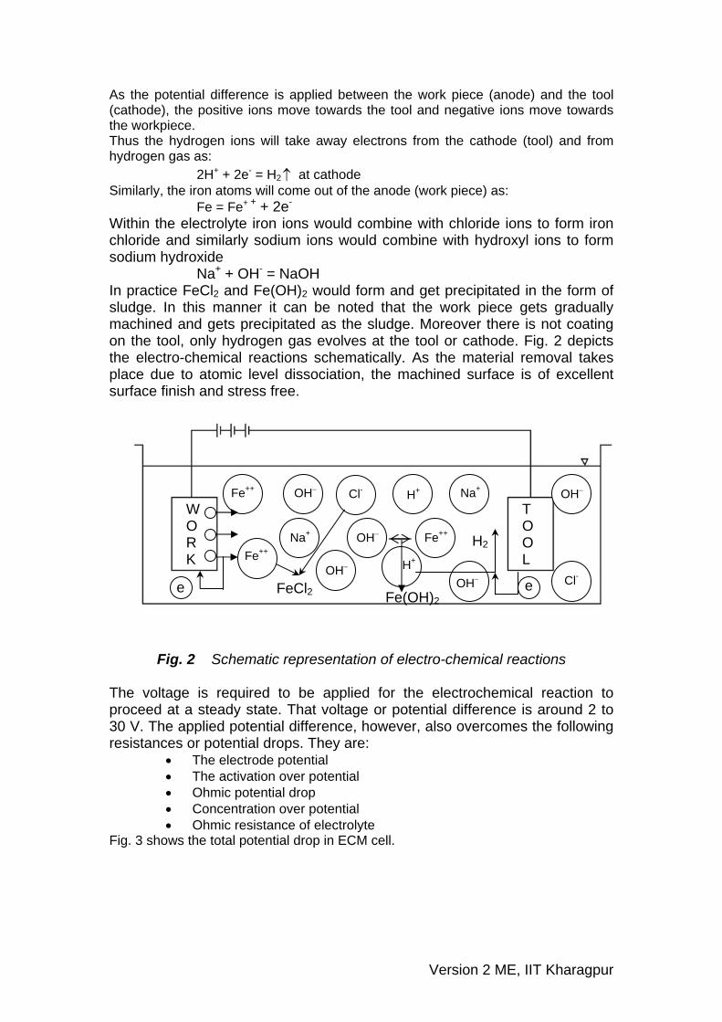
Within the electrolyte iron ions would combine with chloride ions to form iron chloride and similarly sodium ions would combine with hydroxyl ions to form sodium hydroxide Na+ + OH- = NaOH In practice FeCl2 and Fe(OH)2 would form and get precipitated in the form of sludge. In this manner it can be noted that the work piece gets gradually machined and gets precipitated as the sludge. Moreover there is not coating on the tool, only hydrogen gas evolves at the tool or cathode. Fig. 2 depicts the electro-chemical reactions schematically. As the material removal takes place due to atomic level dissociation, the machined surface is of excellent surface finish and stress free.
W O R K
T O O L
Fe++
Fe++
OH−
OH−
OH−
OH− Na+
Na+
Cl-
Cl-
H+
H+
OH− Fe++
Fe(OH)2 FeCl2 e e
H2
Fig. 2 Schematic representation of electro-chemical reactions
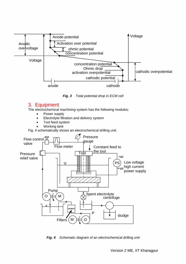
The voltage is required to be applied for the electrochemical reaction to proceed at a steady state. That voltage or potential difference is around 2 to 30 V. The applied potential difference, however, also overcomes the following resistances or potential drops. They are:
• The electrode potential • The activation over potential • Ohmic potential drop • Concentration over potential • Ohmic resistance of electrolyte
Fig. 3 shows the total potential drop in ECM cell.
Version 2 ME, IIT Kharagpur
Anodic overvoltage
Anode potential
Activation over potential ohmic potential
concentration potential
concentration potential Ohmic drop
activation overpotential
anode
cathode
cathodic potential
cathodic overpotential
Voltage
Voltage
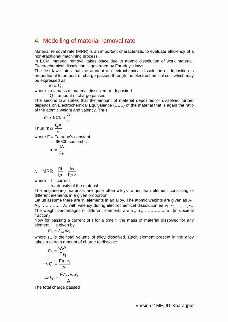
Fig. 3 Total potential drop in ECM cell 3. Equipment The electrochemical machining system has the following modules:
• Power supply • Electrolyte filtration and delivery system • Tool feed system • Working tank
Fig. 4 schematically shows an electrochemical drilling unit.
Flow control valve
Pressure relief valve
Pump
Filters sludge
centrifuge Spent electrolyte
Tool
Flow meter
Pressure gauge
Constant feed to the tool
Low voltage high current power supply
+ve
-ve
PS
O M
M O
P
Fig. 4 Schematic diagram of an electrochemical drilling unit
Version 2 ME, IIT Kharagpur
4. Modelling of material removal rate Material removal rate (MRR) is an important characteristic to evaluate efficiency of a non-traditional machining process. In ECM, material removal takes place due to atomic dissolution of work material. Electrochemical dissolution is governed by Faraday’s laws. The first law states that the amount of electrochemical dissolution or deposition is proportional to amount of charge passed through the electrochemical cell, which may be expressed as:
m Q∝ , where m = mass of material dissolved or deposited Q = amount of charge passed The second law states that the amount of material deposited or dissolved further depends on Electrochemical Equivalence (ECE) of the material that is again the ratio
atomic weigh and valency. Thus of the t
ναα AECEm
Thus ν
α QAm
where F = Faraday’s constant = 96500 coulombs
νF
ItAm =∴
ρνρ FIA
tmMRR ==∴
where I = current ρ= density of the material The engineering materials are quite often alloys rather than element consisting of different elements in a given proportion. Let us assume there are ‘n’ elements in an alloy. The atomic weights are given as A1, A2, ………….., An with valency during electrochemical dissolution as ν1, ν2, …………, νn. The weight percentages of different elements are α1, α2, ………….., αn (in decimal fraction) Now for passing a current of I for a time t, the mass of material dissolved for any element ‘i’ is given by iaim ραΓ= where Γa is the total volume of alloy dissolved. Each element present in the alloy takes a certain amount of charge to dissolve.
i
iii F
AQmν
=
i
iii A
FmQ ν=⇒
i
iiai A
FQ
νραΓ=⇒
The total charge passed
Version 2 ME, IIT Kharagpur
∑== iT QItQ
∑==∴i
iiaT A
FItQ ναρΓ
Now
∑=
Γ=
ii
a
iA
IFt
MRR ναρ.1
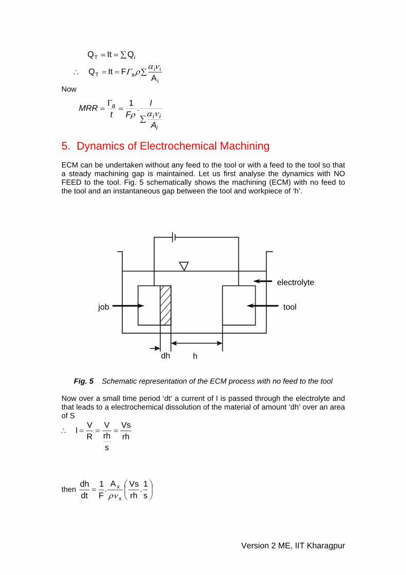
5. Dynamics of Electrochemical Machining ECM can be undertaken without any feed to the tool or with a feed to the tool so that a steady machining gap is maintained. Let us first analyse the dynamics with NO FEED to the tool. Fig. 5 schematically shows the machining (ECM) with no feed to the tool and an instantaneous gap between the tool and workpiece of ‘h’.
job
electrolyte
tool
dh h
Fig. 5 Schematic representation of the ECM process with no feed to the tool
Now over a small time period ‘dt’ a current of I is passed through the electrolyte and that leads to a electrochemical dissolution of the material of amount ‘dh’ over an area of S
rhVs
srhV
RVI ===∴
then ⎟⎠⎞
⎜⎝⎛=
s1.
rhVsA.
F1
dtdh
x
x
ρν
Version 2 ME, IIT Kharagpur
rhV.A.
F1
x
x
ρν=
for a given potential difference and alloy
hc
h1.
rFVA
dtdh
x
x ==ρν
where c = constant
rF
VA
x
x
ρν=
∑
=
i
ii
ArF
Vcνα
ρ
hc
dtdh
=∴
cdthdh =At t = 0, h = ho and at t = t1 and h = h1
∫ ∫=∴1h
oh
t
0dtchdh
ct2hh 2
o21 =−∴
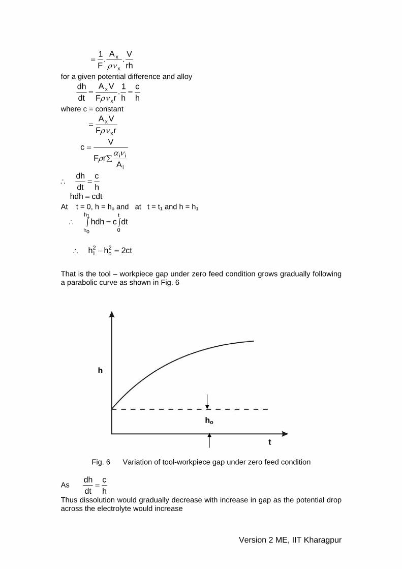
That is the tool – workpiece gap under zero feed condition grows gradually following a parabolic curve as shown in Fig. 6
h
t
ho
Fig. 6 Variation of tool-workpiece gap under zero feed condition
As hc
dtdh
=
Thus dissolution would gradually decrease with increase in gap as the potential drop across the electrolyte would increase
Version 2 ME, IIT Kharagpur
Now generally in ECM a feed (f) is given to the tool
fhc
dtdh
−=∴
Now if the feed rate is high as compared to rate of dissolution, then after sometime the gap would diminish and may even lead to short circuiting. Under steady state condition the gap is uniform i.e. the approach of the tool is compensated by dissolution of the work material. Thus with respect to the tool, the workpiece is not moving
Thus fhc0
dtdh
===
hcf =∴
or h* = steady state gap = c/f Now under practical ECM condition it is not possible to set exactly the value of h* as the initial gap. Thus it is required to be analysed if the initial gap value would have any effect on progress of the process
Now fhc
dtdh
−=
Now chf
*hh'h ==
And c
tf*h
ft't2
==
dtdh.
f1
dtdh.
c/fc/f
'dt'dh
2 ==∴
Thus fhc
dtdh
−=
fc'h
cff*h'h
c'dt'dhf −=−=⇒
⎟⎠⎞
⎜⎝⎛ −
=⇒'h
'h1f'dt'dhf
'h'h1
'dt'dh −=⇒
'dh'h1
'h'dt−
=∴
Now integrating between t’ = 0 to t’ = t’ when h’ changes from ho’ to h1’
'dh'h1
'h'dt't
0
'1h
'oh∫ ∫
−=∴
( )( ) ( )∫ −+∫−−
−=∴'1h
'oh
'1h
'oh'h1d
'h1'h1d't
1h1hlnhh't '
1
'o'
1'o
−
−+−=
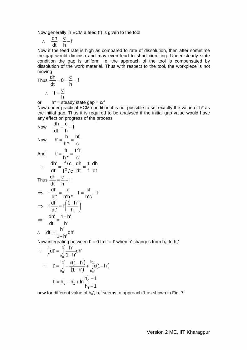
now for different value of ho’, h1’ seems to approach 1 as shown in Fig. 7
Version 2 ME, IIT Kharagpur
h1'
t'
h0= 0
h0= 0.5
1
Simulation for ho'= 0, 0.5, 1, 2, 3, 4, 5
Fig. 7 Variation in steady state gap with time for different initial gap Thus irrespective of initial gap
1cfh1
*hh'h =⇒==
fch =∴
or h1.
rFVA
hcf
x
x
ρν==
si.
FA
rhV.
FAf
x
x
x
x
ρνρν==∴
s/mminMRRsI.
FAf
x
x ==∴ρν
Thus it seems from the above equation that ECM is self regulating as MRR is equal to feed rate. 6. Applications ECM technique removes material by atomic level dissolution of the same by electrochemical action. Thus the material removal rate or machining is not dependent on the mechanical or physical properties of the work material. It only depends on the atomic weight and valency of the work material and the condition that it should be electrically conductive. Thus ECM can machine any electrically conductive work material irrespective of their hardness, strength or even thermal properties. Moreover
Version 2 ME, IIT Kharagpur
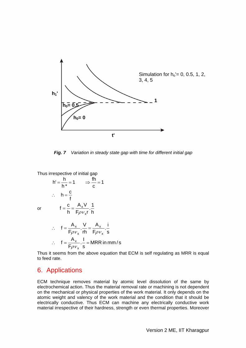
as ECM leads to atomic level dissolution, the surface finish is excellent with almost stress free machined surface and without any thermal damage. ECM is used for
• Die sinking • Profiling and contouring • Trepanning • Grinding • Drilling • Micro-machining
Die sinking
3D profiling
Work
Tool
Fig. 8 Different applications of Electro Chemical Machining
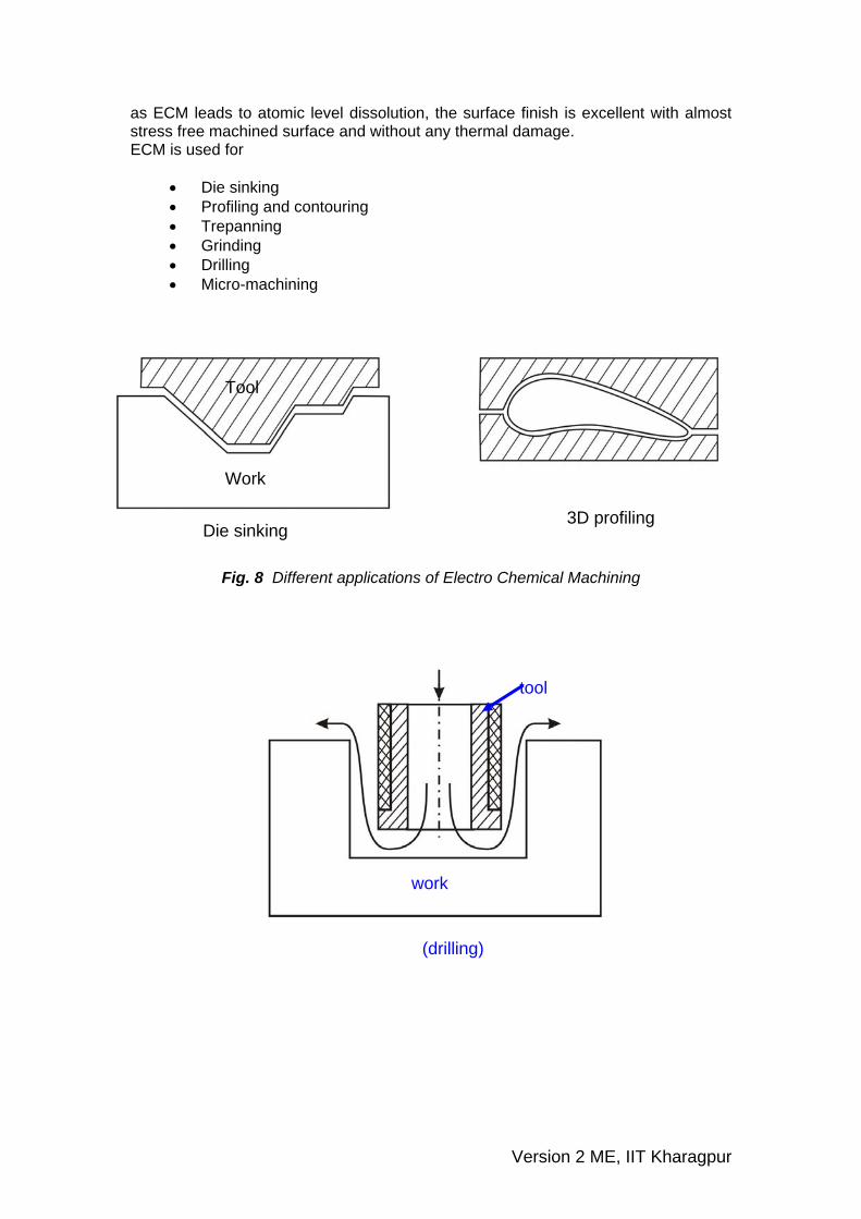
drilling
(drilling)
work
tool
Version 2 ME, IIT Kharagpur
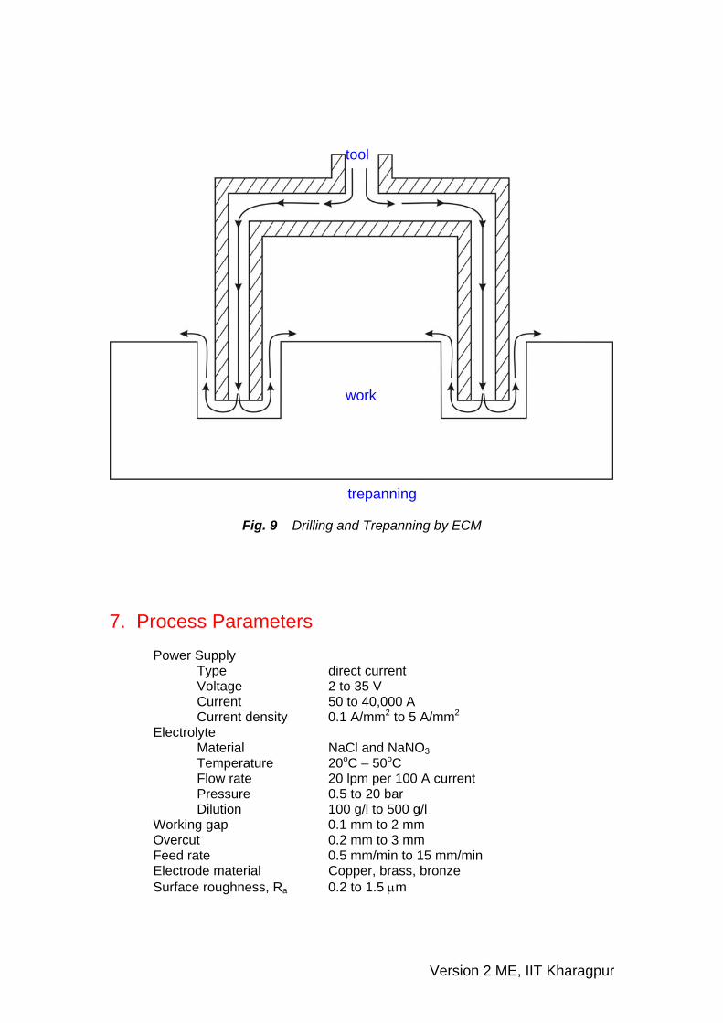
trepanning
tool
work
Fig. 9 Drilling and Trepanning by ECM
7. Process Parameters Power Supply Type direct current Voltage 2 to 35 V Current 50 to 40,000 A Current density 0.1 A/mm2 to 5 A/mm2
Electrolyte Material NaCl and NaNO3 Temperature 20oC – 50oC Flow rate 20 lpm per 100 A current Pressure 0.5 to 20 bar Dilution 100 g/l to 500 g/l Working gap 0.1 mm to 2 mm Overcut 0.2 mm to 3 mm Feed rate 0.5 mm/min to 15 mm/min Electrode material Copper, brass, bronze Surface roughness, Ra 0.2 to 1.5 μm
Version 2 ME, IIT Kharagpur
Quiz Test 1. For ECM of steel which is used as the electrolyte
(a) kerosene (b) NaCl (c) Deionised water (d) HNO3
2. MRR in ECM depends on
(a) Hardness of work material (b) atomic weight of work material (c) thermal conductivity of work material (d) ductility of work material
3. ECM cannot be undertaken for
(a) steel (b) Nickel based superalloy (c) Al2O3 (d) Titanium alloy
4. Commercial ECM is carried out at a combination of
(a) low voltage high current (b) low current low voltage (c) high current high voltage (d) low current low voltage
Problems 1. In electrochemical machining of pure iron a material removal rate of 600 mm3/min
is required. Estimate current requirement. 2. Composition of a Nickel superalloy is as follows:
Ni = 70.0%, Cr = 20.0%, Fe = 5.0% and rest Titanium Calculate rate of dissolution if the area of the tool is 1500 mm2 and a current of 2000 A is being passed through the cell. Assume dissolution to take place at lowest valency of the elements. ANi = 58.71 ρNi = 8.9 νNi = 2 ACr = 51.99 ρCr = 7.19 νCr = 2 AFe = 55.85 ρFe = 7.86 νFe = 2 ATi = 47.9 ρTi = 4.51 νTi = 3 3. In ECM operation of pure iron an equilibrium gap of 2 mm is to be kept. Determine supply voltage, if the total overvoltage is 2.5 V. The resistivity of the electrolyte is 50 Ω-mm and the set feed rate is 0.25 mm/min.
Version 2 ME, IIT Kharagpur
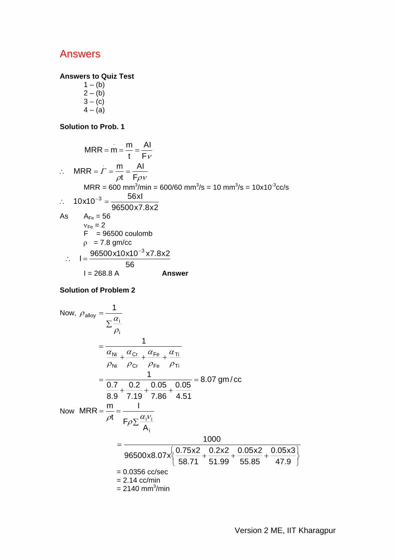
Answers Answers to Quiz Test 1 – (b) 2 – (b) 3 – (c) 4 – (a) Solution to Prob. 1
νFAI
tmmMRR
.===
ρνρΓ
FAI
tmMRR
.===∴
MRR = 600 mm3/min = 600/60 mm3/s = 10 mm3/s = 10x10-3cc/s
2x8.7x96500xI5610x10 3 =∴ −
As AFe = 56 νFe = 2 F = 96500 coulomb ρ = 7.8 gm/cc
562x8.7x10x10x96500I
3−=∴
I = 268.8 A Answer Solution of Problem 2
Now, ∑
=
i
ialloy
1
ρα
ρ
Ti
Ti
Fe
Fe
Cr
Cr
Ni
Ni
1
ρα
ρα
ρα
ρα
+++=
cc/gm07.8
51.405.0
86.705.0
19.72.0
9.87.0
1=
+++=
Now ∑
==
i
ii
AF
It
mMRRνα
ρρ
⎭⎬⎫
⎩⎨⎧ +++
=
9.473x05.0
85.552x05.0
99.512x2.0
71.582x75.0x07.8x96500
1000
= 0.0356 cc/sec = 2.14 cc/min = 2140 mm3/min
Version 2 ME, IIT Kharagpur
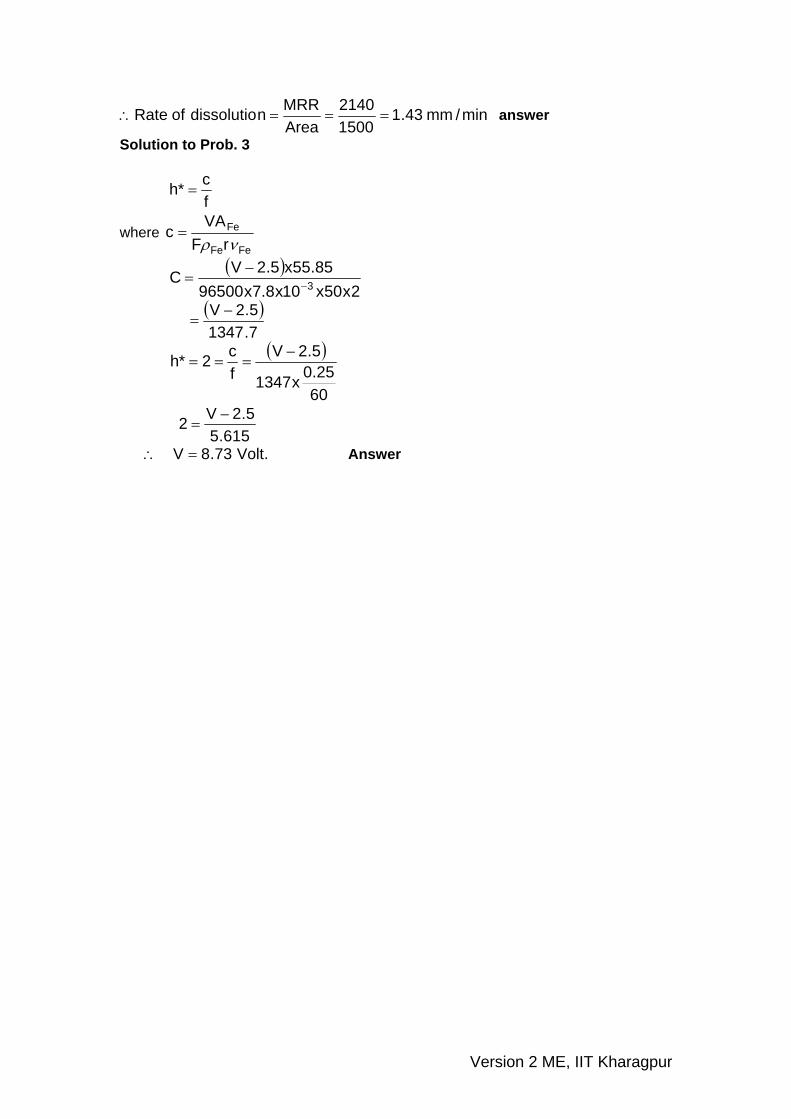
min/mm43.115002140
AreaMRRndissolutioofRate ===∴ answer
Solution to Prob. 3
fc*h =
where FeFe
Fe
rFVA
cνρ
=
( )2x50x10x8.7x96500
85.55x5.2VC 3−−
=
( )
7.13475.2V −
=
( )
6025.0x1347
5.2Vfc2*h −===
615.5
5.2V2 −=
.Volt73.8V =∴ Answer
Version 2 ME, IIT Kharagpur


