Embed Size (px)
Citation preview
Electro static spinning
Several research teams, including some in the former Soviet Union, have investigated the possibilities of forming fiber strands with the aid of electrostatic fields. However, only the process proposed by the Battelle Institute has had a degree of success. The Electrospin Corporation (USA) demonstrated an experimental spinning machine based on this principle at the 1971ITMA in Paris.
However, little has been heard about electrostatic spinning sincethen. In the process based on the Battelle principle (Fig. 2), a roving (2) taken from the roving frame is passed to a conventional double-apron drafting arrangement (3) and is subjected to a draft of up to 80-fold. The fibers exit freely from the front cylinder. They must then be collected to form a fiber strand and twisted to form a yarn. The first of these operations is performed by the electrostatic field, and twisting is carried out in a twist-imparting unit (6). Twisting presents no problems. The complexity of this method lies wholly in the electrostatic field generated between the front roller and the twist element (6) by earthing the front roller and applying a high voltage (about 30 000 - 35 000 V) to the twist element. Thisfield has to accelerate the fibers and guide them toward yarn end(5) while maintaining the elongated configuration of the fibers. When the fibers enter this field, they take up charge and form dipoles, i.e. one end becomes positively charged and the other negatively charged. An open yarn end (5) projects from the twist element into the field. This yarn is negatively charged and is therefore always attracted to the front roller. Due to the dipole pattern, there is thus a relatively high degreeof fiber straightening between the front roller and the twist element. Fibers leaving the roller are accelerated and attracted to the yarn as a result of the charges carried by the two parts. They join continuously to the yarn. Since the yarn rotates, the fibers are bound in. A yarn is formed continuously and is withdrawn by withdrawal rollers (8), to be passed to a take-up device (9) for winding onto a crosswound package. The problem associated with this process is the formation of a
yarn in an electrostatic field, as follows: (a) Charging of the fibers, and hence their behavior in the spinning zone, is dependent upon air humidity. Accordingly, for each fiber type, a specific and highly uniform environment must be created. The machine may need to be air-conditioned. (b) The charge on each fiber, and hence its movement, is dependent upon its mass. Short fibers with low mass will therefore behave differently from long fibers. (c) A limit must be placed upon the number of fibers in the electrostatic field, because otherwise they will cause mutual disturbance when charging and dipole formation takes place. Only fine yarns can therefore be produced. (d) The same effect is observed with high throughput speeds; there is a corresponding limit on the production rate.
Due to these problems, electrostatic spinning has no chance of being used in spinning mills.
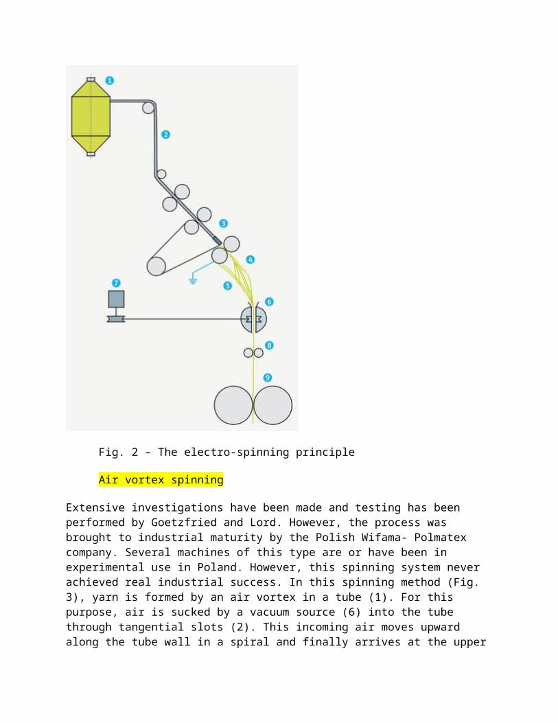
Fig. 2 – The electro-spinning principle
Air vortex spinning
Extensive investigations have been made and testing has been performed by Goetzfried and Lord. However, the process was brought to industrial maturity by the Polish Wifama- Polmatex company. Several machines of this type are or have been in experimental use in Poland. However, this spinning system never achieved real industrial success. In this spinning method (Fig. 3), yarn is formed by an air vortex in a tube (1). For this purpose, air is sucked by a vacuum source (6) into the tube through tangential slots (2). This incoming air moves upward along the tube wall in a spiral and finally arrives at the upper
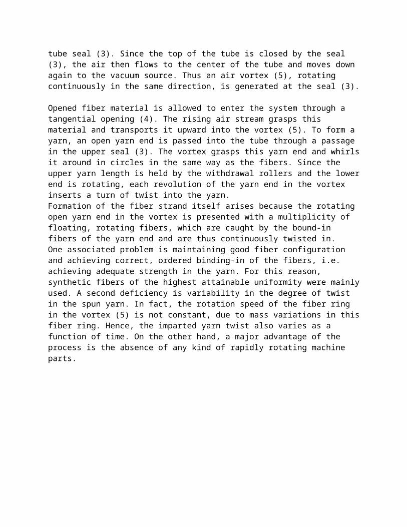
tube seal (3). Since the top of the tube is closed by the seal (3), the air then flows to the center of the tube and moves down again to the vacuum source. Thus an air vortex (5), rotating continuously in the same direction, is generated at the seal (3).
Opened fiber material is allowed to enter the system through a tangential opening (4). The rising air stream grasps this material and transports it upward into the vortex (5). To form a yarn, an open yarn end is passed into the tube through a passage in the upper seal (3). The vortex grasps this yarn end and whirlsit around in circles in the same way as the fibers. Since the upper yarn length is held by the withdrawal rollers and the lowerend is rotating, each revolution of the yarn end in the vortex inserts a turn of twist into the yarn. Formation of the fiber strand itself arises because the rotating open yarn end in the vortex is presented with a multiplicity of floating, rotating fibers, which are caught by the bound-in fibers of the yarn end and are thus continuously twisted in. One associated problem is maintaining good fiber configuration and achieving correct, ordered binding-in of the fibers, i.e. achieving adequate strength in the yarn. For this reason, synthetic fibers of the highest attainable uniformity were mainlyused. A second deficiency is variability in the degree of twist in the spun yarn. In fact, the rotation speed of the fiber ring in the vortex (5) is not constant, due to mass variations in thisfiber ring. Hence, the imparted yarn twist also varies as a function of time. On the other hand, a major advantage of the process is the absence of any kind of rapidly rotating machine parts.
Spinning positions per machine 192
Delivery speed 100 - 150 m/min
Raw material synthetic fibers, 40 - 50 mm
Count range Ne 7.5 - 30; 20 - 80 tex
Form of feedstock drawframe sliver
Type of yarn conventional, single yarn
Yarn characteristics low strength, twist variability, rough surface
Field of end-use undemanding woven goods
Advantages no rapidly rotating parts,simple machine
Special features cotton cannot be spun, due to inadequate yarn quality
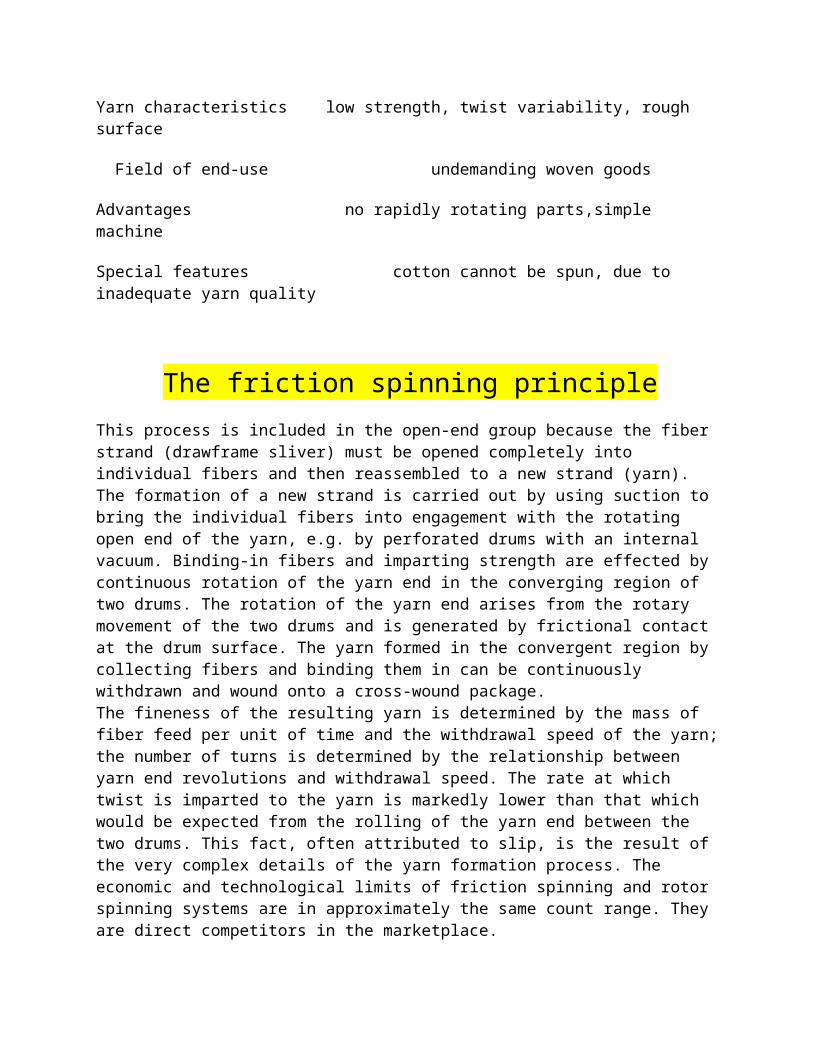
The friction spinning principleThis process is included in the open-end group because the fiber strand (drawframe sliver) must be opened completely into individual fibers and then reassembled to a new strand (yarn). The formation of a new strand is carried out by using suction to bring the individual fibers into engagement with the rotating open end of the yarn, e.g. by perforated drums with an internal vacuum. Binding-in fibers and imparting strength are effected by continuous rotation of the yarn end in the converging region of two drums. The rotation of the yarn end arises from the rotary movement of the two drums and is generated by frictional contact at the drum surface. The yarn formed in the convergent region by collecting fibers and binding them in can be continuously withdrawn and wound onto a cross-wound package. The fineness of the resulting yarn is determined by the mass of fiber feed per unit of time and the withdrawal speed of the yarn;the number of turns is determined by the relationship between yarn end revolutions and withdrawal speed. The rate at which twist is imparted to the yarn is markedly lower than that which would be expected from the rolling of the yarn end between the two drums. This fact, often attributed to slip, is the result of the very complex details of the yarn formation process. The economic and technological limits of friction spinning and rotor spinning systems are in approximately the same count range. They are direct competitors in the marketplace.
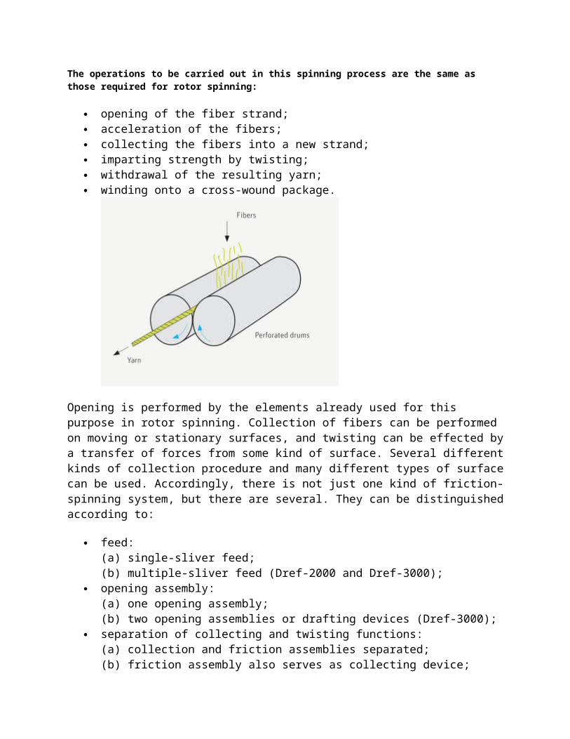
The operations to be carried out in this spinning process are the same as those required for rotor spinning:
opening of the fiber strand; acceleration of the fibers; collecting the fibers into a new strand; imparting strength by twisting; withdrawal of the resulting yarn; winding onto a cross-wound package.
Opening is performed by the elements already used for this purpose in rotor spinning. Collection of fibers can be performed on moving or stationary surfaces, and twisting can be effected bya transfer of forces from some kind of surface. Several differentkinds of collection procedure and many different types of surfacecan be used. Accordingly, there is not just one kind of friction-spinning system, but there are several. They can be distinguishedaccording to:
feed: (a) single-sliver feed; (b) multiple-sliver feed (Dref-2000 and Dref-3000);
opening assembly: (a) one opening assembly; (b) two opening assemblies or drafting devices (Dref-3000);
separation of collecting and twisting functions: (a) collection and friction assemblies separated; (b) friction assembly also serves as collecting device;
number of friction surfaces: (a) one friction surface (Dref-1); (b) two friction surfaces;
type of friction assembly: (a) perforated drums; (b) one perforated drum with one smooth drum (blind drum); (c) two discs; (d) disc and roller in combination; (e) two crossed belts.
The most widely used types are those with the following characteristics:
single-sliver feed; one opening roller; friction assembly also acting as collection device; two friction surfaces; two perforated drums or one perforated drum and one blind
drum in combination.
Advantages and disadvantages
Advantages are as follows:
high delivery speeds; low yarn production costs (lower than those of ring spinning); elimination of rewinding; low end breakage rates; yarn character similar to that of ring-spun yarn; no wrapping fibers; optically good mass evenness (well suited to knitted goods); better and softer handle than that of rotor-spun yarn; smooth yarn appearance.
Disadvantages are:
low yarn strength; high tendency to snarl; higher number of fibers needed in yarn cross-section; difficulty of keeping spinning conditions constant; high air consumption; increasing unevenness and imperfections with increasing spinning
speed, and further reduction in yarn strength.
Wrap spinningThis system is shown in Fig. 18 and Fig. 19. A roving or sliver feedstock (1) is drafted in a three-, four- or five-roller drafting arrangement. The fiber strand delivered runs through a hollow spindle (3) without receiving true twist. In order to impart strength to the strand before it falls apart, a continuous-filament thread (4) is wound around the strand as it emerges from the drafting arrangement. The continuous-filament thread comes from a small, rapidly rotating bobbin (5) mounted on the hollow spindle. Take-off rollers lead the resulting wrap yarn to a winding device. The wrap yarn thus always consists of two components, one twist-free staple-fiber component in the yarn core (a), and a filament (b) wound around the core. This process has been offered by several manufacturers, e.g., Leesona, Mackie, etc. The most common wrap spinning system is ParafiL by the Suessen company, and this process will be briefly described in greaterdetail.
The wrap-spinning principle
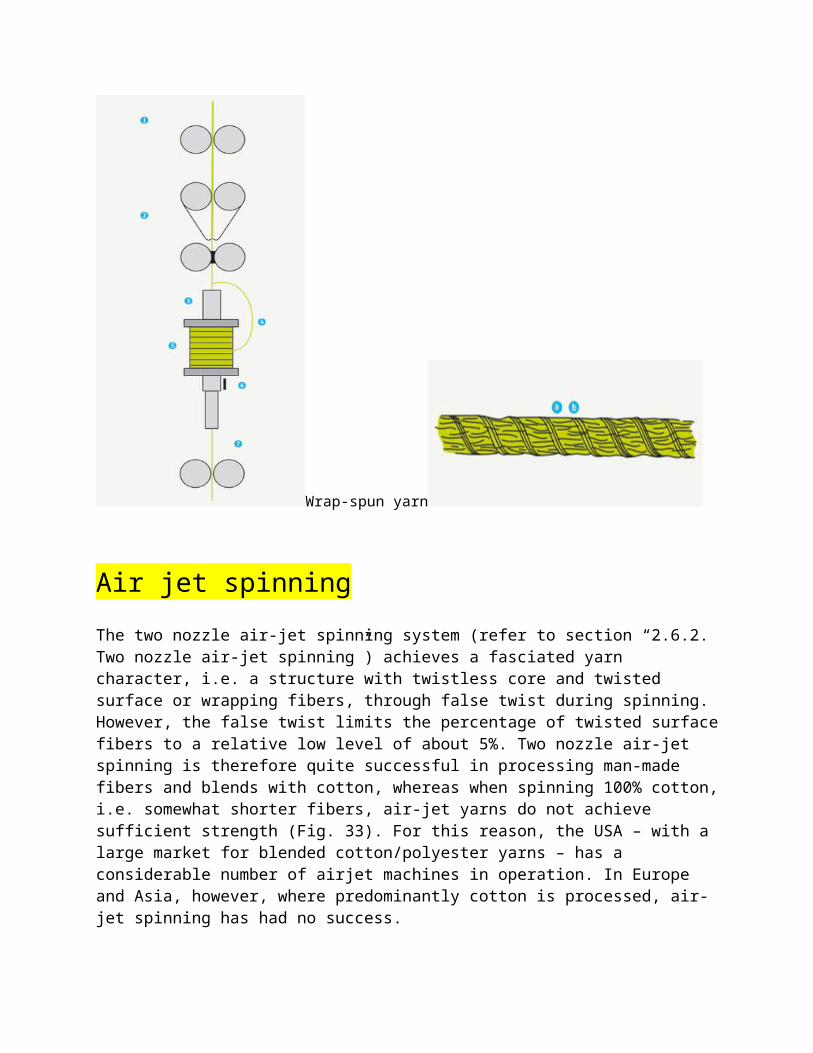
Wrap-spun yarn
Air jet spinningThe two nozzle air-jet spinning system (refer to section “2.6.2. Two nozzle air-jet spinning”) achieves a fasciated yarn character, i.e. a structure with twistless core and twisted surface or wrapping fibers, through false twist during spinning. However, the false twist limits the percentage of twisted surfacefibers to a relative low level of about 5%. Two nozzle air-jet spinning is therefore quite successful in processing man-made fibers and blends with cotton, whereas when spinning 100% cotton,i.e. somewhat shorter fibers, air-jet yarns do not achieve sufficient strength (Fig. 33). For this reason, the USA – with a large market for blended cotton/polyester yarns – has a considerable number of airjet machines in operation. In Europe and Asia, however, where predominantly cotton is processed, air-jet spinning has had no success.
In view of this situation, Murata developed a new spinning process for fasciated yarns. The first patents erase were published in the 1980s. At that time an air vortex was combined with a rotating mechanical element. Since then, Murata has abandoned the rotating element, leaving just the air vortex with no movable mechanical part in the yarn formation zone. Murata presented this new air-jet system under the name of Murata VortexSpinning (MVS) at the Otemas 97 and then at the ITMA 99 (Fig. 34 a). As in two nozzle air-jet spinning, this system has a draftingunit for processing drawframe slivers and no moving parts in the spinning zone. Air-jet spinning, however, does not make use of false twist for yarn formation.
In 2008 Rieter launched its own Air-jet spinning machine J 10 in the market. A double sided machine with 100 individually driven spinning positions and 4 travelling robots aims at pushing the economy of this spinning system further (Fig. 34 b)).
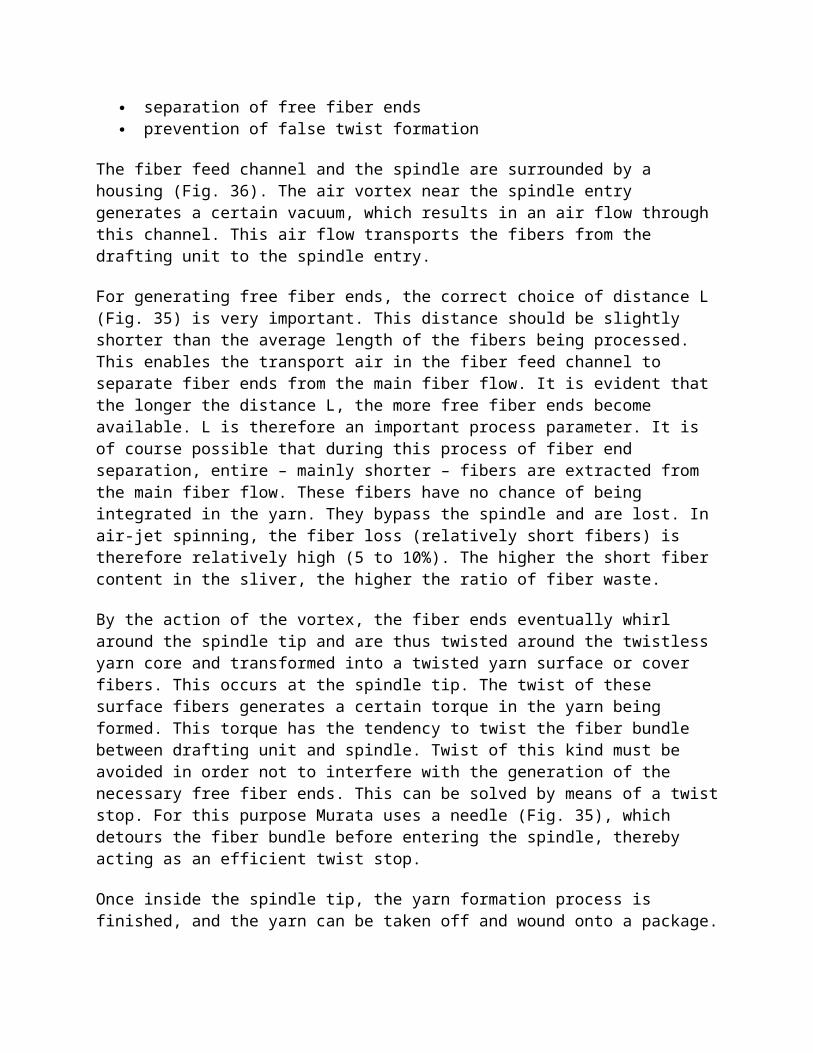
Between the drafting unit and the point of yarn formation at the entry to a stationary spindle (tube), the fibers are conveyed absolutely parallel to each other (Fig. 35). During this fiber transport, a certain number of fiber ends are separated from the main fiber flow. These fiber ends are then twisted around the non-rotating yarn core at the entry of the hollow spindle by the action of a single air vortex.
Compared to airjet spinning, this spinning process permits a considerable increase in the number of surface fibers, i.e. wrapping fibers, to the range of 15 to 30%. This has a positive effect on yarn strength, particularly when spinning cotton. The air-jet process has thus practically eliminated the main handicapof the two nozzle air-jet spinning principle.
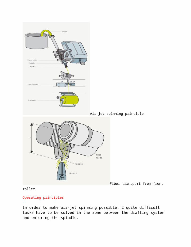
Air-jet spinning principle
Fiber transport from front roller
Operating principles
In order to make air-jet spinning possible, 2 quite difficult tasks have to be solved in the zone between the drafting system and entering the spindle.
separation of free fiber ends prevention of false twist formation
The fiber feed channel and the spindle are surrounded by a housing (Fig. 36). The air vortex near the spindle entry generates a certain vacuum, which results in an air flow through this channel. This air flow transports the fibers from the drafting unit to the spindle entry.
For generating free fiber ends, the correct choice of distance L (Fig. 35) is very important. This distance should be slightly shorter than the average length of the fibers being processed. This enables the transport air in the fiber feed channel to separate fiber ends from the main fiber flow. It is evident that the longer the distance L, the more free fiber ends become available. L is therefore an important process parameter. It is of course possible that during this process of fiber end separation, entire – mainly shorter – fibers are extracted from the main fiber flow. These fibers have no chance of being integrated in the yarn. They bypass the spindle and are lost. In air-jet spinning, the fiber loss (relatively short fibers) is therefore relatively high (5 to 10%). The higher the short fiber content in the sliver, the higher the ratio of fiber waste.
By the action of the vortex, the fiber ends eventually whirl around the spindle tip and are thus twisted around the twistless yarn core and transformed into a twisted yarn surface or cover fibers. This occurs at the spindle tip. The twist of these surface fibers generates a certain torque in the yarn being formed. This torque has the tendency to twist the fiber bundle between drafting unit and spindle. Twist of this kind must be avoided in order not to interfere with the generation of the necessary free fiber ends. This can be solved by means of a twiststop. For this purpose Murata uses a needle (Fig. 35), which detours the fiber bundle before entering the spindle, thereby acting as an efficient twist stop.
Once inside the spindle tip, the yarn formation process is finished, and the yarn can be taken off and wound onto a package.
Raw material requirements
Due to the relatively high percentage of wrapping fibers, the air-jet process is perfectly capable of spinning 100% cotton, from 1˝ staple upwards. For finer yarn counts the cotton has to be combed, of course. Synthetics (up to 40 mm) and cotton/synthetics blends can also be processed without difficulty.
As in ring spinning, however, almost all the yarn characteristicsare improved by the use of longer and finer fibers.
In air-jet spinning, the fibers keep their orientation throughoutthe spinning process. Particularly the core fibers remain absolutely parallel to the axis of the fiber flow. To optimize the spinning results, it is therefore advisable to process slivers with very good fiber parallelization. This also helps to improve the performance of the drafting system. This means that slivers with 3 drawframe passages after carding should be used. As the total draft of the Air-jet machine is limited (180 - 220 fold, technology wise), it can be necessary to process slivers asfine as 2.5 ktex and even finer when spinning fine count yarn.
The winding system has to be capable of handling the high yarn production speeds of the air-jet spinning machine, i.e. up to 450 m/min. The Murata MVS machine is equipped with a traverse system common to all spinning units, as are the rotor spinning machines. But as the delivery speed in air-jet spinning is at least double that in rotor spinning, this leads to a limitation of the possible number of spinning positions per machine side, due to the large increase in massforces in the traversing system with increasing numbers of spinning positions and increasing winding speeds. The Murata MVS machine is single-sided with a maximum of 80 spinning positions whereas Rieter‘s J 10 Air-jet machine is designed as a double sided machine starting inthe market with 100 spinning positions and potential of more spinning units per machine. Because of the single drive concept, the maximum
number of spinning positions is not limited by the winding system. Theyarn packages of Air-jet machine, cylindrical or slightly conical, canbe used directly in downstream processing. Each spinning position of the machine is therefore equipped with a yarn clearer, which efficiently removes any undesired defects from the yarn.
Automation
Air-jet spinning is a high-output process. The air-jet spinning machines are therefore fully automated, of course.
Automation deals with the following functions:
repairing yarn breaks; doffing full yarn packages; insert empty tubes and start spinning.
For repairing yarn break, the machine is equipped with up to 3 carriages (or robots) traveling along the machine. When a yarn isbroken, one of the robots seeks the yarn end on the package, thenit restarts the spinning process and finally it recombines the yarn end from the package with the one which is leaving the nozzle after spinning has restarted. The yarn being spun during the splicing or knotting process is taken care of by a yarn storage system. The repair of an end breakage is therefore not performed by a piecing, as is the case in rotor spinning.
A special carriage travels along the front of the machine for doffing full yarn packages. This carriage takes a full package out of the package holder, puts it down on a conveyer belt and inserts an empty tube into the package holder.
Yarn structure
s already mentioned, air-jet yarns have a fasciated (core / sheat) structure. In fact, air-jet spun yarns consist of a core of essentially parallel fibers without any twist, which is surrounded and bound together by wrapping fibers. These wrapping fibers provide compression forces in the core and thereby the necessary fiber friction in order to achieve the desired yarn
strength. As the wrapping fibers in airjet yarns account for 15 to 30% of the total yarn mass, the core fibers are virtually completely covered by the wrapping fibers, so that air-jet spun yarns look very much like a fully twisted yarn, such as a ring-spun yarn.
This particular structure of the air-jet spun yarns influences the yarn properties, of course. These properties are mainly determined by 2 parameters:
the percentage of wrapping fibers, the twist level of the wrapping fibers.
The percentage of wrapping fibers can be influenced by the spinning draft and by the distance L (Fig. 35), and it is also a function of the yarn count.
The spinning draft is the ratio between the speed of the take-up roller and the speed of delivery roller of the drafting unit. This ratio is usually slightly below 1, which means that the yarntake-up speed is slightly lower than the delivery speed of the drafting unit. If the spinning draft is reduced, the number of wrapping fibers increases.
L is the distance between the outlet nip of the drafting unit andthe spindle. With an increase in distance L, more fiber ends havethe chance to be separated from the main fiber flow, and thus more wrapping fibers are generated.
Experience has shown that with coarser yarn count, the number of wrapping fibers increases, but not at the same rate as the tex count. The percentage of wrapping fibers therefore tends to decrease as the yarns become coarser. While fine count yarns reach a level of up to 30% of wrapping fibers, this percentage drops to 15% or even below for coarse yarns.
The second parameter of great importance for the yarn properties is the wrapping twist. This twist can be influenced by the spinning speed and the flow rate of the compressed air.
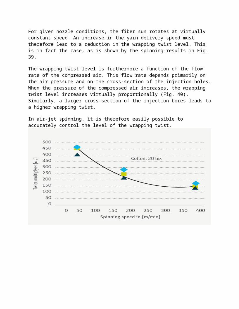
For given nozzle conditions, the fiber sun rotates at virtually constant speed. An increase in the yarn delivery speed must therefore lead to a reduction in the wrapping twist level. This is in fact the case, as is shown by the spinning results in Fig. 39.
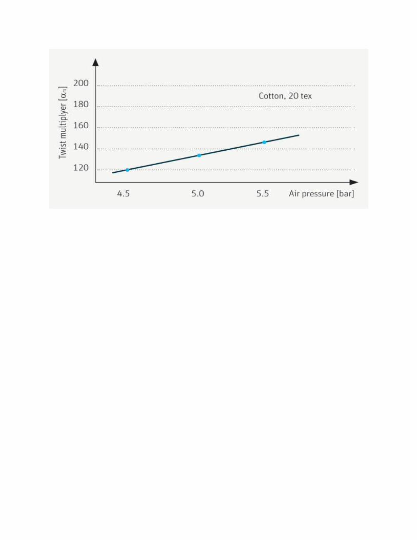
The wrapping twist level is furthermore a function of the flow rate of the compressed air. This flow rate depends primarily on the air pressure and on the cross-section of the injection holes.When the pressure of the compressed air increases, the wrapping twist level increases virtually proportionally (Fig. 40). Similarly, a larger cross-section of the injection bores leads toa higher wrapping twist.
In air-jet spinning, it is therefore easily possible to accurately control the level of the wrapping twist.