Embed Size (px)
Citation preview
ISSN 2070�2051, Protection of Metals and Physical Chemistry of Surfaces, 2014, Vol. 50, No. 1, pp. 72–87. © Pleiades Publishing, Ltd., 2014.Original Russian Text © A.D. Pogrebnyak, A.Sh. Kaverina, M.K. Kylyshkanov, 2014, published in Fizikokhimiya Poverkhnosti i Zashchita Materialov, 2014, Vol. 50, No. 1, pp. 72⎯88.
72
INTRODUCTION
The discharge phenomenon caused by electrolysiswas discovered more than a century ago [1]. Later, itwas studied in detail in the 1930s [2]. However, for thefirst time it was used in practice as late as in the 1960swhen spark discharge was used for applying cadmiumniobate on a cadmium anode from a Nb�containingbath [3, 4]. In the 1970s, Markov at al. developed amethod of applying an oxide on an aluminum anodeunder arcing conditions [5, 6]. In a decade, the tech�nique was improved and named microarc oxidation(which seems not exactly accurate) [7]. In the 1980s,possibilities provided by the use of surface dischargesfor plating oxides on various metals were considered indetail by the groups of Gordienko [8, 9], Markov [10],and Kurze [11–13]. The first attempts to use themethod in industry were made at that time [14, 15].Research groups in the United States and China alsostarted investigations in the field [16, 17]. Because ofthe fragmentary information about the phenomenol�ogy of the processes, the terminology adopted by theaforementioned groups was different. As a result,essentially the same method has been referred to asmicroplasma oxidation, anodic�spark electrolysis,plasma�electrolytic anodic treatment, and anodic oxi�dation at spark discharges. These are typical examplesof the definition of the general concept of plasma�electrolytic oxidation (PEO).
In this work, in order to clarify the basic princi�ples of the aforementioned plasma�electrolytic pro�cesses, we use a general denomination, namelyelectrolytic plasma technology (EPT), which coversa number of methods (oxidation, deposition, satu�ration, etc.) [18–52].
Electrolytic plasma processing of metals is a prom�ising modern method of production of the compo�nents and parts of engines and instruments. Its valueand importance are determined by the possibility touse it instead of a number of conventional processes,which either cannot provide a sufficiently high qualityof the treatment (surface cleaning, sputtering, diffu�sion saturation, etc.) or are related to harmful condi�tions of production and pollution of environment(etching and removal of surface layers of a mate�rial)[52–76].
With the use of EPT, different procedures can becarried out, namely, changes in the surface layers—inparticular, their hardness, surface adhesion of coat�ings, and resistance in an aggressive environment or athigh temperature. The processes involve nitriding,carbonization, silicification, borating, etc. [76–98].
The advantages of EPT are favorable character�istics of gas discharges, such as low persistence andthe possibility of varying parameters in broad ranges[86–101].
Electrolytic plasma technology enables one toobtain coatings with either crystalline or amorphousstructure and a broad spectrum of functionality onaluminum, magnesium, titanium, and zirconiumalloy surfaces. Thickness of the coatings can vary fromseveral microns to several tenths of a millimeter. Thecoatings are characterized by a number of peculiarproperties. They can be decorative, hygienic, wear�and corrosion�resistant, electrical and thermal insu�lating, nonstick, etc. An important aspect is ecologicalsafety of the coatings.
Materials produced by EPT and items made ofthem are widely used in medicine, household appli�ances, automobile construction, and engineering.
Electrolytic Plasma Processing for Plating Coatings and Treating Metals and Alloys
A. D. Pogrebnyaka, A. Sh. Kaverinaa, and M. K. Kylyshkanovb
a Sumy State University, ul. Rymskogo�Korsakova 2, Sumy, 40007 Ukraineb Serikbayev East Kazakhstan State Technical University, ul. A.K. Protozanova 69, Ust�Kamenogorsk, 070004 Kazakhstan
e�mail: [email protected], [email protected] August 2, 2012
Abstract—A review of the methods of electrochemical treatment classified as plasma electrolysis is given.Special attention is paid to the physicochemical processes that proceed in electrolytes and the techniques ofsurface modification and application of protective coatings. The results of investigation of such coatings andsurfaces upon electrolytic plasma processing illustrate the efficiency and effectiveness of the method. Beingan efficient technique of the surface treatment, which involves both the surface cleaning and plating the coat�ing, the plasma�electrolytic method is being rapidly developed and adapted for commercial use at present.
DOI: 10.1134/S2070205114010092
NEW SUBSTANCES, MATERIALS, AND COATINGS
brought to you by COREView metadata, citation and similar papers at core.ac.uk
provided by SocioEconomic Challenges Journal (Sumy State University)
PROTECTION OF METALS AND PHYSICAL CHEMISTRY OF SURFACES Vol. 50 No. 1 2014
ELECTROLYTIC PLASMA PROCESSING FOR PLATING COATINGS 73
TECHNIQUE OF ELECTROLYTIC PROCESSES
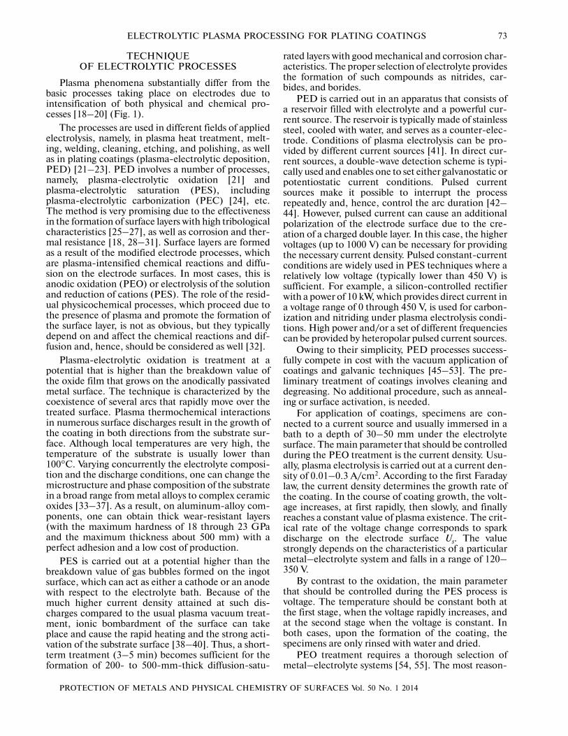
Plasma phenomena substantially differ from thebasic processes taking place on electrodes due tointensification of both physical and chemical pro�cesses [18–20] (Fig. 1).
The processes are used in different fields of appliedelectrolysis, namely, in plasma heat treatment, melt�ing, welding, cleaning, etching, and polishing, as wellas in plating coatings (plasma�electrolytic deposition,PED) [21–23]. PED involves a number of processes,namely, plasma�electrolytic oxidation [21] andplasma�electrolytic saturation (PES), includingplasma�electrolytic carbonization (PEC) [24], etc.The method is very promising due to the effectivenessin the formation of surface layers with high tribologicalcharacteristics [25–27], as well as corrosion and ther�mal resistance [18, 28–31]. Surface layers are formedas a result of the modified electrode processes, whichare plasma�intensified chemical reactions and diffu�sion on the electrode surfaces. In most cases, this isanodic oxidation (PEO) or electrolysis of the solutionand reduction of cations (PES). The role of the resid�ual physicochemical processes, which proceed due tothe presence of plasma and promote the formation ofthe surface layer, is not as obvious, but they typicallydepend on and affect the chemical reactions and dif�fusion and, hence, should be considered as well [32].
Plasma�electrolytic oxidation is treatment at apotential that is higher than the breakdown value ofthe oxide film that grows on the anodically passivatedmetal surface. The technique is characterized by thecoexistence of several arcs that rapidly move over thetreated surface. Plasma thermochemical interactionsin numerous surface discharges result in the growth ofthe coating in both directions from the substrate sur�face. Although local temperatures are very high, thetemperature of the substrate is usually lower than100°C. Varying concurrently the electrolyte composi�tion and the discharge conditions, one can change themicrostructure and phase composition of the substratein a broad range from metal alloys to complex ceramicoxides [33–37]. As a result, on aluminum�alloy com�ponents, one can obtain thick wear�resistant layers(with the maximum hardness of 18 through 23 GPaand the maximum thickness about 500 mm) with aperfect adhesion and a low cost of production.
PES is carried out at a potential higher than thebreakdown value of gas bubbles formed on the ingotsurface, which can act as either a cathode or an anodewith respect to the electrolyte bath. Because of themuch higher current density attained at such dis�charges compared to the usual plasma vacuum treat�ment, ionic bombardment of the surface can takeplace and cause the rapid heating and the strong acti�vation of the substrate surface [38–40]. Thus, a short�term treatment (3–5 min) becomes sufficient for theformation of 200� to 500�mm�thick diffusion�satu�
rated layers with good mechanical and corrosion char�acteristics. The proper selection of electrolyte providesthe formation of such compounds as nitrides, car�bides, and borides.
PED is carried out in an apparatus that consists ofa reservoir filled with electrolyte and a powerful cur�rent source. The reservoir is typically made of stainlesssteel, cooled with water, and serves as a counter�elec�trode. Conditions of plasma electrolysis can be pro�vided by different current sources [41]. In direct cur�rent sources, a double�wave detection scheme is typi�cally used and enables one to set either galvanostatic orpotentiostatic current conditions. Pulsed currentsources make it possible to interrupt the processrepeatedly and, hence, control the arc duration [42–44]. However, pulsed current can cause an additionalpolarization of the electrode surface due to the cre�ation of a charged double layer. In this case, the highervoltages (up to 1000 V) can be necessary for providingthe necessary current density. Pulsed constant�currentconditions are widely used in PES techniques where arelatively low voltage (typically lower than 450 V) issufficient. For example, a silicon�controlled rectifierwith a power of 10 kW, which provides direct current ina voltage range of 0 through 450 V, is used for carbon�ization and nitriding under plasma electrolysis condi�tions. High power and/or a set of different frequenciescan be provided by heteropolar pulsed current sources.
Owing to their simplicity, PED processes success�fully compete in cost with the vacuum application ofcoatings and galvanic techniques [45–53]. The pre�liminary treatment of coatings involves cleaning anddegreasing. No additional procedure, such as anneal�ing or surface activation, is needed.
For application of coatings, specimens are con�nected to a current source and usually immersed in abath to a depth of 30–50 mm under the electrolytesurface. The main parameter that should be controlledduring the PEO treatment is the current density. Usu�ally, plasma electrolysis is carried out at a current den�sity of 0.01–0.3 A/cm2. According to the first Faradaylaw, the current density determines the growth rate ofthe coating. In the course of coating growth, the volt�age increases, at first rapidly, then slowly, and finallyreaches a constant value of plasma existence. The crit�ical rate of the voltage change corresponds to sparkdischarge on the electrode surface Us. The valuestrongly depends on the characteristics of a particularmetal–electrolyte system and falls in a range of 120–350 V.
By contrast to the oxidation, the main parameterthat should be controlled during the PES process isvoltage. The temperature should be constant both atthe first stage, when the voltage rapidly increases, andat the second stage when the voltage is constant. Inboth cases, upon the formation of the coating, thespecimens are only rinsed with water and dried.
PEO treatment requires a thorough selection ofmetal–electrolyte systems [54, 55]. The most reason�
74
PROTECTION OF METALS AND PHYSICAL CHEMISTRY OF SURFACES Vol. 50 No. 1 2014
POGREBNYAK et al.
CLASSICAL ELECTROLYSIS
Main electrode processes
Anodic processes Cathodic processes
Anodic
dissolution
Anodic oxidation
Electrolysis of solution
Reduction of cations
ELECTROLYTIC PLASMA TECHNOLOGY
Heat
treating
Melting
Welding
SolderingExtracting
SaturatingOxidizing
Etching
PolishingCleaning
PLATING
Cataphoresis Plasmochemical reactionDiffusion Heating
Intensification of physicochemical processes
PLASMA ELECTROLYSIS
Fig. 1. A scheme of physicochemical processes typical of plasma electrolysis and main conventional electrode reactions that pro�ceed during electrolytic plasma treatment [98].
able electrolytes are fluorides with complex behavior(NaF, KF), electrolytes that provide weak passivationof the metal, and those in which metal passivation isstrong, e.g., boric acids and salts of carbonic and phos�phoric acids, inorganic polymers (silicate, aluminate,wolframite, and molybdenite), and alkaline metalphosphates, which can form polymer anions. In theseelectrolytes, spark�discharge voltages can easily beachieved. With respect to the contribution to the com�position of coatings, electrolytes can be divided intothe following groups:
(i) solutions that supply oxygen solely to the coat�ing;
(ii) electrolytes that contain anionic componentsand contribute some other elements to the coating;
(iii) electrolytes that contain cationic componentsand contribute some other elements; and
(iv) suspensions that provide cataphoretic trans�port of macroparticles, which are included in the coat�ing.
In electrolytes of the second and third groups,coatings are formed both due to the oxidation of sub�strate and the inclusion of electrolyte components inthe surface layer. As a result, a broad spectrum of sur�face compositions with various properties can be pro�duced. Therefore, such bases are considered as themost promising. Colloidal solutions of sodium orpotassium silicate, as well as multicomponent silicate�based electrolytes, are widely used for PEO treatment.
In addition to silicate, the bath can contain sub�stances that increase the conductivity of the electro�lyte, e.g., Na (0.5 to 2.0 g/L), NaOH or KOH (1 to50 g/L), provide the formation of an oxide layer, whichinvolves stabilizing components, e.g., Na2B4O7 ⋅
PROTECTION OF METALS AND PHYSICAL CHEMISTRY OF SURFACES Vol. 50 No. 1 2014
ELECTROLYTIC PLASMA PROCESSING FOR PLATING COATINGS 75
10H2O (40 g/L), glycerin (10 g/L), Na2CO3 or К2СО3(≤500 g/L), and modifying components, e.g., NaAlO2(2–20 g/L) or Na6P6O18 (≤150 g/L). For some partic�ular purposes, in order to provide cataphoretic effectsduring oxidation, fine powders of solid materials withhigh melting points and/or dry paste (for improvingthe wear and friction resistance) can be added to thebath. Thus, depending on the electrolyte compositionand the electrode polarity, one can use PEO and PEStechniques profitably.
PROCESSES OF PLASMA�ELECTROLYTIC TREATMENT
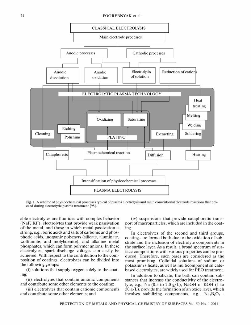
Figure 2 shows results of treatment of a wire (AISI1080, high�carbon steel) in a dynamic system whereelectrolyte was supplied at a velocity of 3–5 L/min andthe wire was moved through the EPT chamber (reac�tor) at a velocity of 3 m/min. The voltammetric curvereflects different stages of the process.
At low voltages U1, the current increases in propor�tion to the voltage in conformity with the Faraday law.Under these conditions, a gas, typically H2, is liber�ated, as shown in Fig. 2b. When the voltage is furtherincreased, the U2 point (>90 V), which is interesting inview of the electrocatalytic plasma processes, isreached. This range is characterized by the appearanceof glowing gas, which is unstable, as indicated by the
substantial variations in the current values. The cur�rent shown in Fig. 2 under these conditions is themean value of the actually oscillating current.Figures 2c and 2d illustrate the instability, which isaccompanied by spark ignition of the gas. The appear�ance of glowing gas was determined by evaporation ofelectrolyte close to the electrode (in this case, cath�ode) due to the Joule heat. Experimental studies [56]carried out neglecting the Joule heat showed that nor�mal electrolysis is impossible without the formation ofa glowing gas, because there is no electrolytic gas lib�eration that would increase with an increase in thevoltage.
The color of the glow depends on the nature ofmetals involved in the alloy composition. For exam�ple, orange plasma was observed in the presence ofsodium ions, while blue plasma is seen with zinc ions.The colors are determined by the plasma discharge onthe working surface of the specimen when differentelements emit light waves of certain lengths.
When the voltage is increased to the U3 value, thecathode is continuously enveloped in gas plasma,which is characterized by a substantial decrease in thecurrent values. These EPT conditions correspond tothe stable plasma when one can carry out a controlledsurface treatment (Fig. 2e). The conditions were dis�covered by Kellogg and are called Kellogg’s range.
(d)
(c)
(b)
(e)
(f)
(а)
Cu
rren
t, А
Voltage, V
Gas liberation
Spark ignition
Continuous plasma
Arcing regime
U1
U2
U3
U4
Fig. 2. Voltammetric curve of the plasma�electrolytic process under cathodic conditions [41].
envelope
76
PROTECTION OF METALS AND PHYSICAL CHEMISTRY OF SURFACES Vol. 50 No. 1 2014
POGREBNYAK et al.
The critical current density under conditions of theappearance of stable plasma is known to depend on anumber of factors, including the shape (planar orround), size and orientation of electrode. As wasshown in experimental studies, when the diameter ofan anode wire increases, the formation of stableplasma takes place at the higher voltage and currentdensity. The result agrees with the data obtained inindependent studies of the cathodic conditions. Whenthe voltage is increased to U4 value, both intensivesparking and a plasma envelope around the electrodeare observed (Fig. 2f). These aggressive conditions canproduce a baneful effect on the surface of a specimen[54, 55].
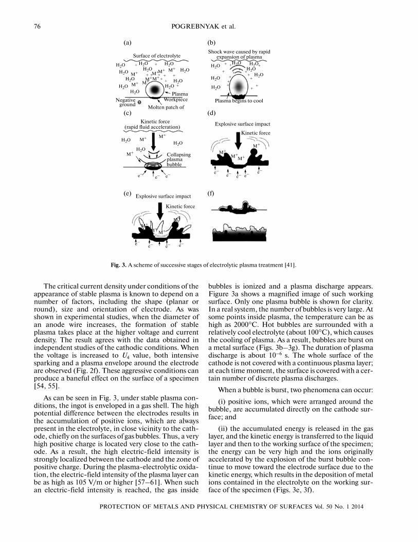
As can be seen in Fig. 3, under stable plasma con�ditions, the ingot is enveloped in a gas shell. The highpotential difference between the electrodes results inthe accumulation of positive ions, which are alwayspresent in the electrolyte, in close vicinity to the cath�ode, chiefly on the surfaces of gas bubbles. Thus, a veryhigh positive charge is located very close to the cath�ode. As a result, the high electric�field intensity isstrongly localized between the cathode and the zone ofpositive charge. During the plasma�electrolytic oxida�tion, the electric�field intensity of the plasma layer canbe as high as 105 V/m or higher [57–61]. When suchan electric�field intensity is reached, the gas inside
bubbles is ionized and a plasma discharge appears.Figure 3a shows a magnified image of such workingsurface. Only one plasma bubble is shown for clarity.In a real system, the number of bubbles is very large. Atsome points inside plasma, the temperature can be ashigh as 2000°C. Hot bubbles are surrounded with arelatively cool electrolyte (about 100°C), which causesthe cooling of plasma. As a result, bubbles are burst ona metal surface (Figs. 3b–3g). The duration of plasmadischarge is about 10–6 s. The whole surface of thecathode is not covered with a continuous plasma layer;at each time moment, the surface is covered with a cer�tain number of discrete plasma discharges.
When a bubble is burst, two phenomena can occur:
(i) positive ions, which were arranged around thebubble, are accumulated directly on the cathode sur�face; and
(ii) the accumulated energy is released in the gaslayer, and the kinetic energy is transferred to the liquidlayer and then to the working surface of the specimen;the energy can be very high and the ions originallyaccelerated by the explosion of the burst bubble con�tinue to move toward the electrode surface due to thekinetic energy, which results in the deposition of metalions contained in the electrolyte on the working sur�face of the specimen (Figs. 3e, 3f).
Surface of electrolyte
Negative Workpiece
Molten patch of
Shock wave caused by rapid
Plasma begins to cool
Kinetic force
Collapsing
Explosive surface impact
(а) (b)
(c) (d)
(e) (f)
Plasma
Kinetic force
Explosive surface impact
Kinetic force
expansion of plasma
ground
(rapid fluid acceleration)
plasma bubble
H2O M+
+
e–e–
e– e– e–
e–e–e–
e–e– e– e–
H2OH2O
H2OH2O
H2O
H2O
M+
M+
M+M+
M+
M+
M+
M+ M+
M+
M+M+
M+
M+
+
+
++
++
+
++
+++
+
++
+ ++ +
++
+
M+
M+M+
M+
H2O
H2O
H2O
H2O H2O H2O H2OH2O
H2O
H2O+H2O
H2O
H2O
H2O
Fig. 3. A scheme of successive stages of electrolytic plasma treatment [41].
PROTECTION OF METALS AND PHYSICAL CHEMISTRY OF SURFACES Vol. 50 No. 1 2014
ELECTROLYTIC PLASMA PROCESSING FOR PLATING COATINGS 77
During plasma�electrolytic treatment, the motionof ions is determined chiefly by their accelerationthrough the plasma and their consumption at the bub�ble burst. EPT is a dynamic system where the electro�lyte flow at a high velocity through the reactor cham�ber results in rapid transfer of ions to the plasma layer.Hydrodynamic flow, combined with efficient ionictransport during the deposition in the course of EPT,results in a high deposition rate.
DIFFUSION AND PLASMA�CHEMICAL REACTIONS. CATAPHORETIC EFFECTS
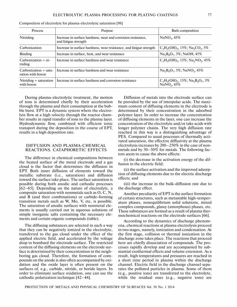
The difference in chemical compositions betweenthe heated surface of the metal electrode and a gascloud is the factor that determines the diffusion inEPT. Both inner diffusion of elements toward themetallic substrate (i.e., saturation) and diffusiontoward the surface take place. The surface saturation ispossible during both anodic and cathodic processes[62–65]. Depending on the nature of electrolyte, acomposite saturation with nonmetals such as O, C, N,and B (and their combinations) or carbide�formingtransition metals such as W, Mo, V, etc, is possible.The saturation of anodic surfaces with nonmetal ele�ments is usually carried out in aqueous solutions ofsimple inorganic salts containing the necessary ele�ments and certain organic compounds (table).
The diffusing substances are selected in such a waythat they can be negatively ionized in the electrolyte,transferred to the gas cloud under the effect of theapplied electric field, and accelerated by the voltagedrop to bombard the electrode surface. The restrictedcontent of the diffusing elements on the electrode sur�face is determined by their concentration in the neigh�boring gas cloud. Therefore, the formation of com�pounds on the anode is also often accompanied by oxi�dation and the oxide layer is often present on thesurfaces of, e.g., carbide, nitride, or boride layers. Inorder to eliminate surface oxidation, one can use thecathodic polarization technique [42–44].
Diffusion of metals into the electrode surface canbe provided by the use of interpolar acids. The maxi�mum content of diffusing elements in the electrode isdetermined by their concentration in the adsorbedpolymer layer. In order to increase the concentrationof diffusing elements in the layer, one can increase theconcentration of the electrolyte and/or take acids withlonger polymer chains. The very high diffusion ratereached in this way is a distinguishing advantage ofPES. Compared to usual processes of thermally acti�vated saturation, the effective diffusivity at the plasmaelectrolysis increases by 200–250% in the case of non�metals and by 30–50% for metals. The following fac�tors seem to cause the above effects:
(i) the decrease in the activation energy of the dif�fusion in the electric field;
(ii) the surface activation and the improved adsorp�tion of diffusing elements due to the electric dischargeeffects; and
(iii) the increase in the bulk�diffusion rate due tothe discharge effect.
Another peculiarity of EPT is the surface formationof certain structures, such as metastable high�temper�ature phases, nonequilibrium solid solutions, mixedcomplex compounds, glassy (amorphous) phases, etc.These substances are formed as a result of plasma ther�mochemical reactions on the electrode surfaces [66].
According to the dynamics of discharge phenom�ena, chemical reactions at plasma electrolysis proceedin two stages, namely, ionization and condensation. Atthe first stage, collision or thermal ionization in thedischarge zone takes place. The reactions that proceedhere are chiefly dissociation of compounds. The pro�cesses rapidly develop and are accompanied by sub�stantial exothermal effects and volume extension. As aresult, high temperatures and pressures are reached ina short time period in plasma within the dischargechannel. Electric field in the discharge channel sepa�rates the polluted particles in plasma. Some of them(e.g., positive ions) are transferred to the electrolyte,while the residual ones (e.g., negative ions) are
Composition of electrolyte for plasma�electrolytic saturation [98]
Process Purpose Bath composition
Nitriding Increase in surface hardness, wear and corrosion resistance, and fatigue strength
NaNO3, 45%
Carbonization Increase in surface hardness, wear resistance, and fatigue strength C3H5(OH)3, 15%; Na2CO3, 5%
Binding Increase in surface, heat, and wear resistance Na2B4O7, 3%; NaOH, 45%
Carbonization + ni�triding
Increase in surface hardness and wear resistance C3H5(OH)3, 15%; Na2NO2, 45%
Carbonization + satu�ration with boron
Increase in surface hardness and wear resistance Na2B4O7, 3%; NaNO2, 45%
Nitriding + saturation with boron
Increase in surface hardness and corrosion resistance C3H5(OH)3, 15%; Na2B4O7, 3% NaNO2, 45%
78
PROTECTION OF METALS AND PHYSICAL CHEMISTRY OF SURFACES Vol. 50 No. 1 2014
POGREBNYAK et al.
involved in the processes on the electrode surface. Atthe second stage, the temperature rapidly drops andplasma components form substances that are con�densed within discharge channels. Insofar as the cool�ing rate may be as high as 108 K/s, one can find pecu�liar high�temperature phases, supersaturated solu�tions, and nonequilibrium compounds on the surfaceat a temperature that is nearly equal to that of the envi�ronment. Thus, α� and γ�Al2O3, TiO2, α�SiO2,δ�Nb2O5, ClNb2O6, Al2TiO5, BaTiO3, NaNbO3,3Al2O3–2SiO2, and other compounds can be formedon the electrode surfaces.
The phase composition is an important factor thatdetermines the actual mechanical or tribological effectof the surface layer [67–69]. Predicting the phasecomposition of the treated layer is a topical appliedtask in the field of EPT. It is difficult to determine theaccurate composition of the solid solution, especiallytaking into account the difficulties in estimating com�plex kinetic parameters that describe all the reactionsproceeding in the discharge zone. A more productiveapproach that enables one to obtain a quantitativecharacteristic of the phase composition of the layerwas proposed in [70] for plasma�electrolytic oxidationof aluminum. Its efficiency is determined by step�by�step thermodynamic calculation of the equilibriumreaction products at the ionization and condensation�discharge stages. Calculations are based on maximiza�tion of entropy of a heterophase multicomponent sys�tem, which models the discharge channel. With theuse of the approach, one can study the effects of dis�charge parameters on the phase composition, as wellas the effects of the channel composition, its geometry,and thermodynamic state (ρ and T). Studying theproperties can be useful for selecting and optimizingthe conditions of electrolytic plasma technology.
Cataphoretic effects, i.e., the transfer of macropar�ticles both from and to the electrode surface, can beobserved in strong electric fields reached at the plasmaelectrolysis. The transfer is promoted by hydration andcharging of macro particles, as well as hydrodynamiceffects caused by the surface heating and convection.The outer transfer can be used for cleaning surfacesand removing coatings and films formed with othermethods. Transfer to the surface is also widely used forincreasing the efficiency of plating coatings. The sizesof macro particles and the energy density at plasmaelectrolysis are two main factors that affect cataphore�sis (and hence, the surface structure) in the course ofthe formation of coatings. First of all, the deposition ofsubmacro particles with the use of cataphoresis fromcolloidal solutions and the deposition of macro parti�cles from suspensions can be considered indepen�dently. Colloidal solutions of inorganic polymers, suchas silicates, aluminates, polyphosphates, tungstates,molybdenates, etc., as well as powder suspensions ofoxides, nitrides, carbides, borides, etc., can be used forthe formation of a broad variety of coatings. Second,
the electric conditions of the plasma electrolysis canconditionally be divided into three main groups:
(i) conditions that facilitate sublimation of macro�particles in a discharge around electrode;
(ii) conditions that promote sintering of macropar�ticles on the electrode surface; and
(iii) conditions that provide complete synthesis ofmacroparticles within the growing film.
Although the particular current conditions andelectric parameters of the process depend on theselected electrolyte–electrode system, the aforemen�tioned detailed classifications enable one to predictpossible structures of the deposited coatings, namely,(I) pseudodiffusion, (II) agglomeration, or (III) com�pact synthesis.
PROPERTIES OF EPT COATINGS
Microstructures
The combination of mechanical, thermal, chemi�cal, and electric methods in electrolytic plasma tech�nology enables one to produce surfaces with peculiarmicrostructures. The microstructure of anEPT�cleaned steel surface has been thoroughly stud�ied with the use of focused�ion�beam (FIB) and trans�mission�electron microscopy (TEM) [71, 72]. Thesurface microstructure was found to involve a layerwith a thickness of 150–250 nm and a grain size of10⎯20 nm [73]. Later studies of EPT�cleaned steelsurfaces with the use of X�ray diffraction (XRD) andTEM showed that the surface microstructure consistsof two or three layers. The upper amorphous layer, aswell as the lower layers, is composed of nanoscaledgrains, which gradually increase in size until the bulkmicrostructure is attained. The thickness of the nan�ograin layer was noted to increase with the increase inthe duration of EPT.
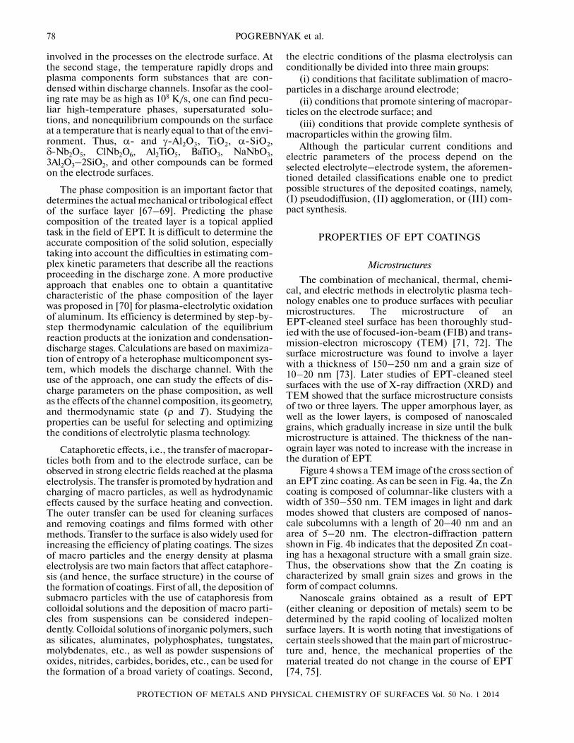
Figure 4 shows a TEM image of the cross section ofan EPT zinc coating. As can be seen in Fig. 4a, the Zncoating is composed of columnar�like clusters with awidth of 350–550 nm. TEM images in light and darkmodes showed that clusters are composed of nanos�cale subcolumns with a length of 20–40 nm and anarea of 5–20 nm. The electron�diffraction patternshown in Fig. 4b indicates that the deposited Zn coat�ing has a hexagonal structure with a small grain size.Thus, the observations show that the Zn coating ischaracterized by small grain sizes and grows in theform of compact columns.
Nanoscale grains obtained as a result of EPT(either cleaning or deposition of metals) seem to bedetermined by the rapid cooling of localized moltensurface layers. It is worth noting that investigations ofcertain steels showed that the main part of microstruc�ture and, hence, the mechanical properties of thematerial treated do not change in the course of EPT[74, 75].
PROTECTION OF METALS AND PHYSICAL CHEMISTRY OF SURFACES Vol. 50 No. 1 2014
ELECTROLYTIC PLASMA PROCESSING FOR PLATING COATINGS 79
Plating of Coatings
The role of metallic coatings in the improvement ofdifferent surface characteristics, such as corrosionresistance, wear resistance, etc., is very important.
The formation of a protective layer is as follows: thesurface of a specimen is covered with an aluminum�based alloy. The layer is applied by gas�thermal spray�ing with the use of electro�arc sputtering of wires. Thetechnique provides the formation of a sufficientlycompact aluminum alloy coating with a porosity of nohigher than 4%. Pores in the coating are closed and donot affect the subsequent oxidation. Thickness ofoxide coatings on the surfaces of compact materialsdepends on the electric field intensity and can varyfrom 5 to 1000 μm [75–77]. In the course of electrol�ysis, oxygen is liberated at the anode and, being acti�vated by electric discharges, oxidizes the metal. Withan increase in the thickness of the oxide layer, the elec�tric field intensity should be increased to stabilizemicroarc discharges and preserve the electric condi�tions of the oxidation. The oxidation is attenuating,and to intensify it, one should increase the electricfield intensity to a value that provides breakdown ofthe oxide layer and the formation of arc discharges.The duration of discharges varies in a range of 1 ×10⎯3 s. Electric discharges at surface sites with thehigher local conductivity provide the formation of acompact oxide layer with closed pores.
In the course of the operation of such an item,pores decrease the heat conductivity and act as com�pensators of voltage drops, which meets the require�ment of the protection of items against high�tempera�ture oxidation.
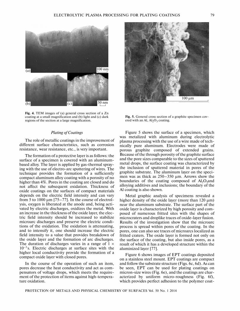
Figure 5 shows the surface of a specimen, whichwas metalized with aluminum during electrolyticplasma processing with the use of a wire made of tech�nically pure aluminum. Electrodes were made ofporous graphite composed of extended grains.Because of the through porosity of the graphite surfaceand the pore sizes comparable to the sizes of sputteredmetal drops, the surface coating was characterized bythe inclusion of sputtered material in pores of thegraphite substrate. The aluminum layer on the speci�men was as thick as 250–350 μm. Arrows show theboundaries of the coating composed of Al2O3andalloying additives and inclusions; the boundary of theAl coating is also shown.
Metal graphic analysis of specimens revealed ahigher density of the oxide layer (more than 120 μm)near the aluminum substrate. The surface part of theoxide layer is characterized by high porosity and com�posed of numerous fritted sites with the shapes ofmicrocraters and droplike traces of oxide�layer fusion.Results of the investigation show that the microarcprocess is spread within pores of the coating. In thepores, one can also see traces of microarcs localized asfritted craters. The oxide layer is formed not only onthe surface of the coating, but also inside pores, as aresult of which it has a developed structure within thealuminized layer [77].
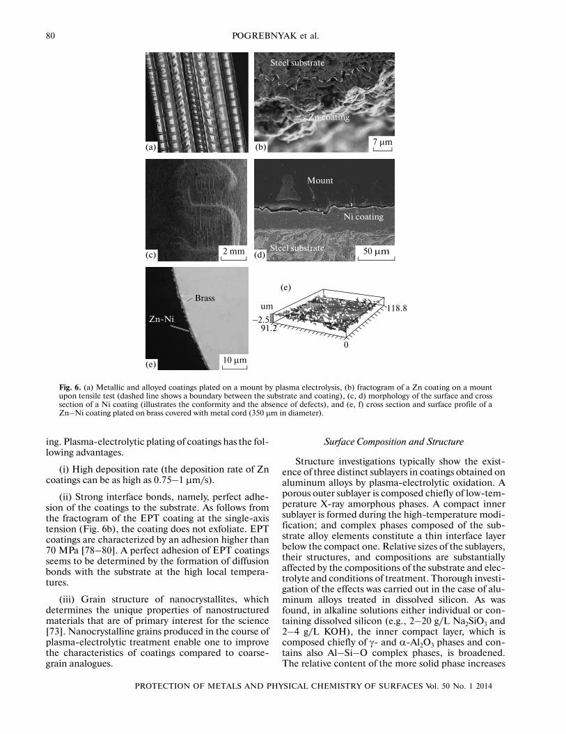
Figure 6 shows images of EPT coatings depositedon a stainless steel mount. EPT coatings are compactand follow the substrate structure (Figs. 6c, 6d). As canbe seen, EPT can be used for plating coatings onmicron�size wires (Fig. 6e), and the coatings are char�acterized by uniform micro�roughness (Fig. 6f),which provides perfect adhesion to the polymer coat�
(c)(b)
(а) 100 nm
50 nm
Fig. 4. TEM images of (a) general cross section of a Zncoating at a small magnification and (b) light and (c) darkregions of the section at a large magnification.
100 µm
Fig. 5. General cross section of a graphite specimen cov�ered with an Al, Al2O3 coating.
80
PROTECTION OF METALS AND PHYSICAL CHEMISTRY OF SURFACES Vol. 50 No. 1 2014
POGREBNYAK et al.
ing. Plasma�electrolytic plating of coatings has the fol�lowing advantages.
(i) High deposition rate (the deposition rate of Zncoatings can be as high as 0.75–1 μm/s).
(ii) Strong interface bonds, namely, perfect adhe�sion of the coatings to the substrate. As follows fromthe fractogram of the EPT coating at the single�axistension (Fig. 6b), the coating does not exfoliate. EPTcoatings are characterized by an adhesion higher than70 MPa [78–80]. A perfect adhesion of EPT coatingsseems to be determined by the formation of diffusionbonds with the substrate at the high local tempera�tures.
(iii) Grain structure of nanocrystallites, whichdetermines the unique properties of nanostructuredmaterials that are of primary interest for the science[73]. Nanocrystalline grains produced in the course ofplasma�electrolytic treatment enable one to improvethe characteristics of coatings compared to coarse�grain analogues.
Surface Composition and Structure
Structure investigations typically show the exist�ence of three distinct sublayers in coatings obtained onaluminum alloys by plasma�electrolytic oxidation. Aporous outer sublayer is composed chiefly of low�tem�perature X�ray amorphous phases. A compact innersublayer is formed during the high�temperature modi�fication; and complex phases composed of the sub�strate alloy elements constitute a thin interface layerbelow the compact one. Relative sizes of the sublayers,their structures, and compositions are substantiallyaffected by the compositions of the substrate and elec�trolyte and conditions of treatment. Thorough investi�gation of the effects was carried out in the case of alu�minum alloys treated in dissolved silicon. As wasfound, in alkaline solutions either individual or con�taining dissolved silicon (e.g., 2–20 g/L Na2SiO3 and2–4 g/L KOH), the inner compact layer, which iscomposed chiefly of γ� and α�Al2O3 phases and con�tains also Al–Si–O complex phases, is broadened.The relative content of the more solid phase increases
7 µm
Steel substrate
Zn coating
2 mm 50 µm
Mount
Ni coating
Steel substrate
10 µm
Zn�Ni
Brassum
−2.591.2
0
118.8
(а) (b)
(c) (d)
(e)
(е)
Fig. 6. (a) Metallic and alloyed coatings plated on a mount by plasma electrolysis, (b) fractogram of a Zn coating on a mountupon tensile test (dashed line shows a boundary between the substrate and coating), (c, d) morphology of the surface and crosssection of a Ni coating (illustrates the conformity and the absence of defects), and (e, f) cross section and surface profile of aZn⎯Ni coating plated on brass covered with metal cord (350 µm in diameter).
PROTECTION OF METALS AND PHYSICAL CHEMISTRY OF SURFACES Vol. 50 No. 1 2014
ELECTROLYTIC PLASMA PROCESSING FOR PLATING COATINGS 81
with an increase in the current density. The content ofα�aluminum can be as high as 60% in coatings formedon copper�containing aluminum substrates, while theγ�Al2O3 phase is predominantly formed on magne�sium�containing aluminum alloys [80–83].
The increase in the concentration of silicate in theelectrolyte results in the accelerated growth of thecoating due to the inclusion of silicon in its structureand formation of Al–Si–O complex phases. In thisway, an interlayer with a two�phase structure appearsin which the phase ratio can vary in a broad range.
When silicon is present in an alkaline electrolyte,the distribution of elements in the thickness of thecoating changes depending on the type of particlesthat contain silicon. For example, coatings formed ina 2�g/L alkaline solution containing no silicon arecharacterized by a homogeneous distribution of alu�minum in the depth and the presence of special alloyadditives, such as copper and magnesium, which areaccumulated close to the outer surface according tothe peculiarities of their interaction with oxygen.
The addition of sodium silicate in the amount of15 g/L to the electrolyte results in penetration of3⎯5 at % silicon in the coating and the substantialdecrease in the concentration of copper and magne�sium, which migrate to the interlayer. The location ofthe maximum content of copper and magnesium isalso shifted toward the substrate. When silicon is intro�duced as a fine powder, its content in the coatingincreases (to 40–60% on the surface), but its distribu�tion in the depth of the layer is no longer homoge�neous. Accordingly, concentration profiles of alumi�num and other alloy components also change. Whenalkaline solutions that contain dissolved silicon areused, the degree of uniformity of the thickness of thecoating depends on the composition of the bath.
Homogeneous coatings can be obtained only in thepresence of certain balanced combinations of siliconand alkali, and the increase in the concentration of sil�icate leads to stronger growth of the coating at thespecimen edges where the polycondensation of siliconis facilitated due to the more intense sparking [84].
By contrast, an increase in the alkali concentrationcauses the local dissolution of the oxide layer and theformation of pits on the surface. Oxide coatingsobtained in concentrated silicate solutions (50–300 g/L) are thicker and more homogeneous. How�ever, their outer layers are also thicker and can consti�tute up to 90% of the whole thickness of the coating.Such layers are usually X�ray amorphous and contain40–43% silicon, 1–4% aluminum, 1–4% sodium,and 49–58% oxygen. Silicate coatings typically have afoamlike structure with a high bulk porosity and rela�tively low mechanical properties. Composition of thecoatings can be changed only by introducing addi�tional substances to the electrolyte. For the purpose,electrolytes that contain Al2O3, Fe3O4, TiO2, MgO, orCr2O3 fine powders are often used. However, because
of the high bulk porosity, the distribution of elementsin the coatings is very heterogeneous.
Similarly to the usual treatment accompanied bythermal chemical diffusion, the surface layers pro�duced on steels by plasma�electrolytic carbonitriding(PEN/C) involve two sublayers. The inner diffusionlayer of pearlite and preserved austenite (that involvesdiffusion elements in solid solution) and the outer“white” layer primarily formed of iron nitrides andcarbides have a diffuse interface. Characteristics of thestructure zones depend on the voltage and conditionsof treatment, as well as on the nature of the diffusingelement.
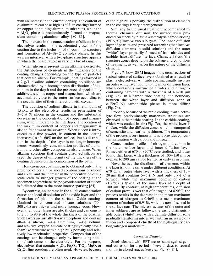
Figure 7 shows SEM images of the cross sections oftypical saturated surface layers obtained as a result ofplasma electrolysis. A nitride coating usually involvesan outer white layer bound to the inner diffusion layer,which contains a mixture of nitrides and nitrogen�containing carbides with a thickness of 40–50 μm(Fig. 7a). In a carbonitride coating, the boundarybetween the white layer and diffusion zone ofα�Fe(C⎯N) carbonitride phases is more diffuse(Fig. 7b).
Probably because of the rapid cooling in an electro�lyte flow, predominantly martensite structures areobserved in the nitride coating. In the carbide coating,which was cooled in air (Fig. 7c), the white layer isthicker, while the diffusion zone, which is composedof cementite and pearlite, is thinner. The temperatureof the process is very important, as it provides concur�rent saturation with carbon and nitrogen.
Concentration profiles of nitrogen and carbon inthe outer surface layer and inner diffusion layersformed either at 670 or 820°C were studied, and it wasfound that layers with a thickness of 100–150 μm oreven up to 200 μm can be formed as early as in 3 min.
Nevertheless, the distribution of elements withinthe layer is not the same under different conditions. At670°C, an outer white layer with a thickness of 10–20 μm that contains 5–6% N and only 0.7% C isformed, while the maximum content of carbon(1.23%) is typical of the inner layer at a depth of100 μm. By contrast, at high temperatures, diffusionof carbon prevails over that of nitrogen. At 820°C, theprocess results in the decrease in the mean maximumcontent of nitrogen to 0.46% at a mean maximumcontent of carbon of 0.91%, which is now observed inthe surface part. The microstructures of the outer andinner sublayers are as follows: the easily distinguish�able outer (white) layer with a definite diffusion zonegradually transforms into a layer with an increased dif�fusion and composed chiefly of the high�quality car�bon/nitrogen martensite.
Corrosion Behavior
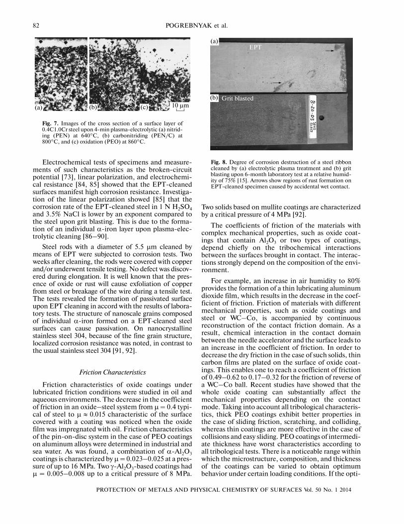
Steels cleaned with EPT are resistant against gen�eral corrosion for a period of several days to severalmonths in closed spaces (see e.g., Fig. 8) [84].
82
PROTECTION OF METALS AND PHYSICAL CHEMISTRY OF SURFACES Vol. 50 No. 1 2014
POGREBNYAK et al.
Electrochemical tests of specimens and measure�ments of such characteristics as the broken�circuitpotential [73], linear polarization, and electrochemi�cal resistance [84, 85] showed that the EPT�cleanedsurfaces manifest high corrosion resistance. Investiga�tion of the linear polarization showed [85] that thecorrosion rate of the EPT�cleaned steel in 1 N H2SO4and 3.5% NaCl is lower by an exponent compared tothe steel upon grit blasting. This is due to the forma�tion of an individual α�iron layer upon plasma�elec�trolytic cleaning [86–90].
Steel rods with a diameter of 5.5 μm cleaned bymeans of EPT were subjected to corrosion tests. Twoweeks after cleaning, the rods were covered with copperand/or underwent tensile testing. No defect was discov�ered during elongation. It is well known that the pres�ence of oxide or rust will cause exfoliation of copperfrom steel or breakage of the wire during a tensile test.The tests revealed the formation of passivated surfaceupon EPT cleaning in accord with the results of labora�tory tests. The structure of nanoscale grains composedof individual α�iron formed on a EPT�cleaned steelsurfaces can cause passivation. On nanocrystallinestainless steel 304, because of the fine grain structure,localized corrosion resistance was noted, in contrast tothe usual stainless steel 304 [91, 92].
Friction Characteristics
Friction characteristics of oxide coatings underlubricated friction conditions were studied in oil andaqueous environments. The decrease in the coefficientof friction in an oxide–steel system from μ = 0.4 typi�cal of steel to μ ≈ 0.015 characteristic of the surfacecovered with a coating was noticed when the oxidefilm was impregnated with oil. Friction characteristicsof the pin�on�disc system in the case of PEO coatingson aluminum alloys were determined in industrial andsea water. As was found, a combination of α�Al2O3coatings is characterized by μ = 0.023–0.025 at a pres�sure of up to 16 MPa. Two γ�Al2O3�based coatings hadμ = 0.005–0.008 up to a critical pressure of 8 MPa.
Two solids based on mullite coatings are characterizedby a critical pressure of 4 MPa [92].
The coefficients of friction of the materials withcomplex mechanical properties, such as oxide coat�ings that contain Al2O3 or two types of coatings,depend chiefly on the tribochemical interactionsbetween the surfaces brought in contact. The interac�tions strongly depend on the composition of the envi�ronment.
For example, an increase in air humidity to 80%provides the formation of a thin lubricating aluminumdioxide film, which results in the decrease in the coef�ficient of friction. Friction of materials with differentmechanical properties, such as oxide coatings andsteel or WC–Co, is accompanied by continuousreconstruction of the contact friction domain. As aresult, chemical interaction in the contact domainbetween the needle accelerator and the surface leads toan increase in the coefficient of friction. In order todecrease the dry friction in the case of such solids, thincarbon films are plated on the surface of oxide coat�ings. This enables one to reach a coefficient of frictionof 0.49–0.62 to 0.17–0.32 for the friction of reverse ofa WC–Co ball. Recent studies have showed that thewhole oxide coating can substantially affect themechanical properties depending on the contactmode. Taking into account all tribological characteris�tics, thick PEO coatings exhibit better properties inthe case of sliding friction, scratching, and colliding,whereas thin coatings are more effective in the case ofcollisions and easy sliding. PEO coatings of intermedi�ate thickness have worst characteristics according toall tribological tests. There is a noticeable range withinwhich the microstructure, composition, and thicknessof the coatings can be varied to obtain optimumbehavior under certain loading conditions. If the opti�
(b) (c)(а) 10 µm
Fig. 7. Images of the cross section of a surface layer of0.4C1.0Cr steel upon 4�min plasma�electrolytic (a) nitrid�ing (PEN) at 640°C, (b) carbonitriding (PEN/C) at800°C, and (c) oxidation (PEO) at 860°C.
(b)
(а)
Grit blasted
EPT
Fig. 8. Degree of corrosion destruction of a steel ribboncleaned by (a) electrolytic plasma treatment and (b) gritblasting upon 6�month laboratory test at a relative humid�ity of 75% [15]. Arrows show regions of rust formation onEPT�cleaned specimen caused by accidental wet contact.
PROTECTION OF METALS AND PHYSICAL CHEMISTRY OF SURFACES Vol. 50 No. 1 2014
ELECTROLYTIC PLASMA PROCESSING FOR PLATING COATINGS 83
mum characteristics of aluminum PEO coatings withrespect to loading are in question, there are numerousvariants of developing new multilayer and hybrid�duplex coatings for aluminum protection [93–96].
Surface Doping
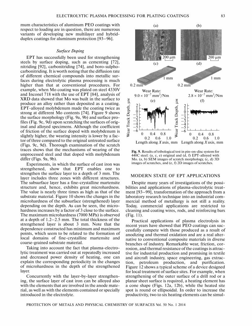
EPT has successfully been used for strengtheningsteels by surface doping, such as cementing [72],nitriding [92], carbonitriding [74], and boro�sulpho�carbonitriding. It is worth noting that the diffusion rateof different chemical compounds into metallic sur�faces during electrolytic plasma processing is muchhigher than that at conventional procedures. Forexample, when Mo coating was plated on steel 4330Vand Inconel 718 with the use of EPT [84], analysis ofXRD data showed that Mo was built in the surface toproduce an alloy rather than deposited as a coating.EPT�alloyed molybdenum made the coating twice asstrong at different Mo contents [74]. Figure 9 showsthe surface morphology (Fig. 9a, 9b) and surface pro�files (Fig. 9c, 9d) upon scratching the surfaces of orig�inal and alloyed specimens. Although the coefficientof friction of the surface doped with molybdenum isslightly higher, the wearing intensity is lower by a fac�tor of three compared to the original untreated surface(Figs. 9c, 9d). Thorough examination of the scratchtraces shows that the mechanisms of wearing of theunprocessed steel and that doped with molybdenumdiffer (Figs. 9a, 9b).
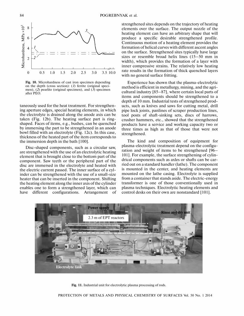
Experiments, in which the surface of cast iron wasstrengthened, show that EPT enables one tostrengthen the surface layer to a depth of 3 mm. Thelayer includes three zones with different structures.The subsurface layer has a fine�crystalline martensitestructure and, hence, exhibits great microhardness.The value is nearly three times as high as that of thesubstrate material. Figure 10 shows the changes in themicrohardness of the subsurface (strengthened) layerdepending on the depth. As can be seen, the micro�hardness increases by a factor of 3 close to the surface.The maximum microhardness (7000 MPa) is observedat a depth of 1.2–2.5 mm. The total thickness of thestrengthened layer is about 3 mm. Note that thedependence constructed has minimum and maximumpoints, which seem to be related to the formation oflocal domains of fine�crystalline martensite andcoarse�grained substrate material.
Taking into account the fact that plasma�electro�lytic treatment was carried out at repeatedly increasedand decreased power density of heating, one canexplain the corresponding periodicity in the changesof microhardness in the depth of the strengthenedlayer.
Concurrently with the layer�by�layer strengthen�ing, the surface layer of cast iron can be alloyed alsowith the elements that are involved in the anode mate�rial, as well as with the elements contained or speciallyintroduced in the electrolyte.
MODERN STATE OF EPT APPLICATIONS
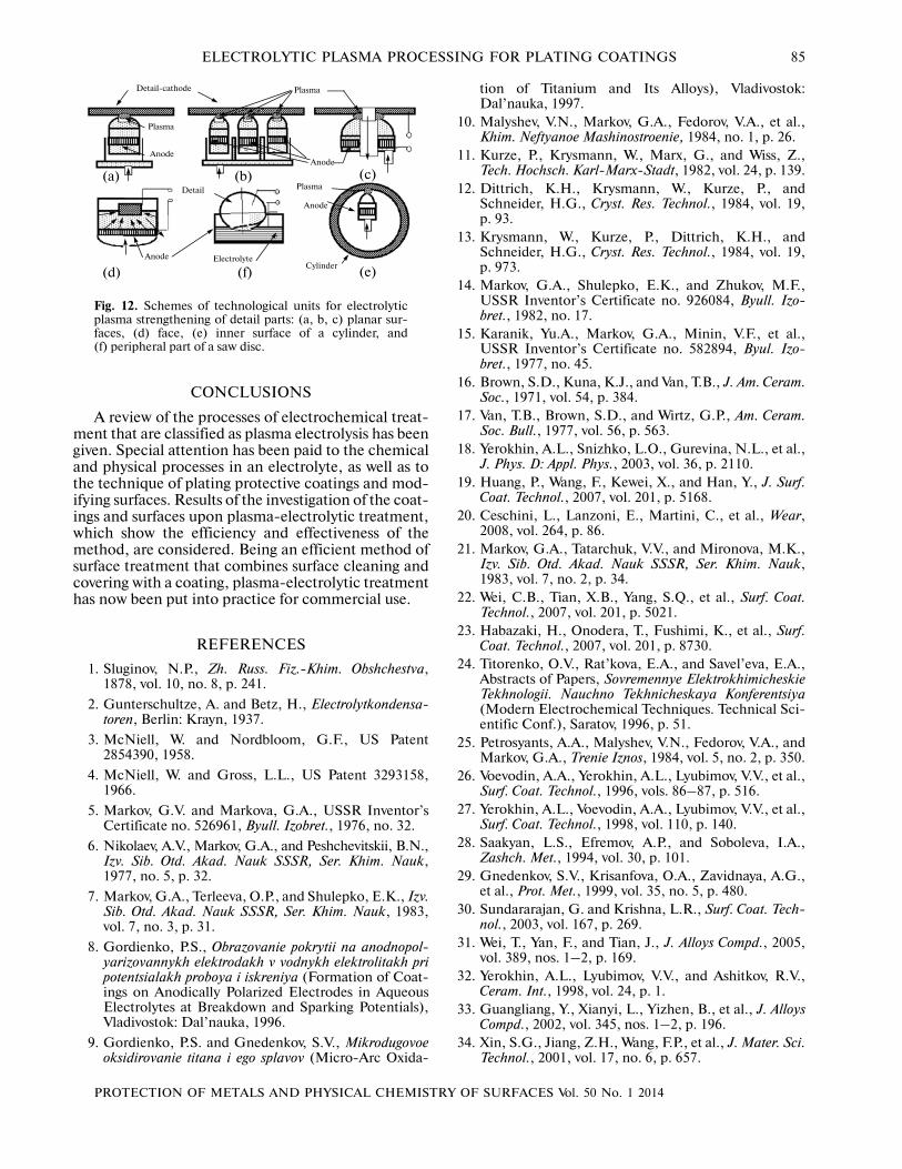
Despite many years of investigations of the possi�bilities and applications of plasma�electrolytic treat�ment [93–99], transformation of the approach from alaboratory research technique into an industrial com�mercial method of metallurgy is not still a reality.Today, commercial applications are restricted tocleaning and coating wires, rods, and reinforcing bars(Fig. 11).
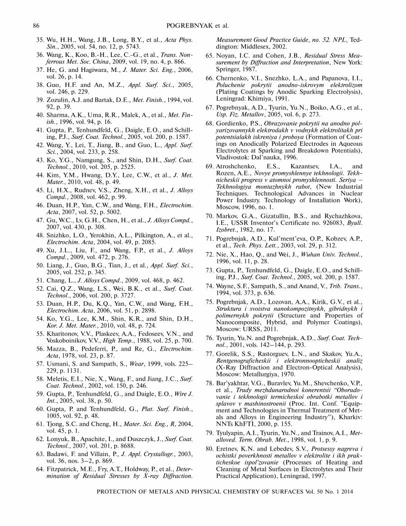
Practical applications of plasma electrolysis inrecent years have showed that PEO coatings can suc�cessfully compete with those produced as a result ofanodizing and thermal oxidation and are a real alter�native to conventional composite materials in diversebranches of industry. Remarkable wear, friction, cor�rosion, and thermal resistance of the coatings is attrac�tive for industrial production and promising in textileand aircraft industry, space engineering, gas extrac�tion, petroleum production, and purification.Figure 12 shows a typical scheme of a device designedfor local treatment of surface sites. For example, whenstrengthening of the outer surface of a drill rod or aplanar sheet surface is required, a heating element hasa cone shape (Figs. 12a, 12b), while the heated sitespot is round or ellipsoidal. In order to increase theproductivity, two to six heating elements can be simul�
210
–1–2–3–4–5
00.2
0.41.0
0.80.6
–6
(b)
(c)
(а)
200 µm 200 µm
Wea
r T
rack
Dep
th, µ
м
Wear Rate:
Length along X axis, mm
210
–1–2–3–4–5
00.2
0.41.0
0.80.6
–6
Wea
r T
rack
Dep
th, µ
м
Length along X axis, mm
9.0 × 10⁻⁷ mm3/NmWear Rate:
2.8 × 10⁻⁷ mm3/Nm
0.2 mm
1 mm
(d)
(e) (f)
1 mm
0.2 mm
Fig. 9. Results of tribological test in pin�on�disc system for440C steel: (a, c, e) original and (d, f) EPT�alloyed withMo. (a, b) SEM images of scratch morphology, (c, d) 3Dimages of scratches, and (e, f) 2D images of scratches.
84
PROTECTION OF METALS AND PHYSICAL CHEMISTRY OF SURFACES Vol. 50 No. 1 2014
POGREBNYAK et al.
taneously used for the heat treatment. For strengthen�ing aperture edges, special heating elements, in whichthe electrolyte is drained along the anode axis can betaken (Fig. 12b). The heating surface part is ring�shaped. Faces of items, e.g., bushes, can be quenchedby immersing the part to be strengthened in an anodebowl filled with an electrolyte (Fig. 12c). In this case,thickness of the heated part of the item corresponds tothe immersion depth in the bath [100].
Disc�shaped components, such as a circular saw,are strengthened with the use of an electrolytic heatingelement that is brought close to the bottom part of thecomponent. Saw teeth or the peripheral part of thedisc are immersed in the electrolyte and heated withthe electric current passed. The inner surface of a cyl�inder can be strengthened with the use of a small�sizeheater that can be inserted in the component. Shiftingthe heating element along the inner axis of the cylinderenables one to form a strengthened layer, which canhave different configurations. Arrangement of
strengthened sites depends on the trajectory of heatingelements over the surface. The output nozzle of theheating element can have an arbitrary shape that willproduce a specific desirable strengthened profile.Continuous motion of a heating element provides theformation of helical curves with different ascent angleson the surface. Strengthened sites typically have largesizes or resemble broad helix lines (15–50 mm inwidth), which provides the formation of a layer withinner compressive strains. The relatively low heatingrate results in the formation of thick quenched layerswith no general surface fritting.
Experience has shown that the plasma�electrolyticmethod is efficient in metallurgy, mining, and the agri�cultural industry [85–87], where certain local parts ofitems and components should be strengthened to adepth of 10 mm. Industrial tests of strengthened prod�ucts, such as knives and saws for cutting metal, drillpipe lock joints, panlines of scraper production lines,tool posts of shaft�sinking sets, discs of harrows,crusher hammers, etc., showed that the strengthenedproducts have a service and working capacity two orthree times as high as that of those that were notstrengthened.
The kind and composition of equipment forplasma�electrolytic treatment depend on the configu�ration and weight of items to be strengthened [96–101]. For example, the surface strengthening of cylin�drical components such as axles or shafts can be car�ried out on a standard handler (lathe). The componentis mounted in the center, and heating elements aremounted on the lathe casing. Electrolyte is suppliedfrom a container that stands aside. The electric�energytransformer is one of those conventionally used inplasma techniques. Electrolytic heating elements andcontrol desks on their own are nonstandard [101].
8
6
4
2
3.02.52.01.51.00.50 3.5 10.0
Mic
roh
ard
nes
s, М
Pа ×
103
1
2
3
Fig. 10. Microhardness of cast iron specimen dependingon the depth (cross section): (1) ferrite (original speci�men), (2) pearlite (original specimen), and (3) specimenafter PEO.
2.3 m of EPT reactors
Electrolyte tank
Rinse and dry unitPower supply
Fig. 11. Industrial unit for electrolytic plasma processing of rods.
PROTECTION OF METALS AND PHYSICAL CHEMISTRY OF SURFACES Vol. 50 No. 1 2014
ELECTROLYTIC PLASMA PROCESSING FOR PLATING COATINGS 85
CONCLUSIONS
A review of the processes of electrochemical treat�ment that are classified as plasma electrolysis has beengiven. Special attention has been paid to the chemicaland physical processes in an electrolyte, as well as tothe technique of plating protective coatings and mod�ifying surfaces. Results of the investigation of the coat�ings and surfaces upon plasma�electrolytic treatment,which show the efficiency and effectiveness of themethod, are considered. Being an efficient method ofsurface treatment that combines surface cleaning andcovering with a coating, plasma�electrolytic treatmenthas now been put into practice for commercial use.
REFERENCES
1. Sluginov, N.P., Zh. Russ. Fiz.�Khim. Obshchestva,1878, vol. 10, no. 8, p. 241.
2. Gunterschultze, A. and Betz, H., Electrolytkondensa�toren, Berlin: Krayn, 1937.
3. McNiell, W. and Nordbloom, G.F., US Patent2854390, 1958.
4. McNiell, W. and Gross, L.L., US Patent 3293158,1966.
5. Markov, G.V. and Markova, G.A., USSR Inventor’sCertificate no. 526961, Byull. Izobret., 1976, no. 32.
6. Nikolaev, A.V., Markov, G.A., and Peshchevitskii, B.N.,Izv. Sib. Otd. Akad. Nauk SSSR, Ser. Khim. Nauk,1977, no. 5, p. 32.
7. Markov, G.A., Terleeva, O.P., and Shulepko, E.K., Izv.Sib. Otd. Akad. Nauk SSSR, Ser. Khim. Nauk, 1983,vol. 7, no. 3, p. 31.
8. Gordienko, P.S., Obrazovanie pokrytii na anodnopol�yarizovannykh elektrodakh v vodnykh elektrolitakh pripotentsialakh proboya i iskreniya (Formation of Coat�ings on Anodically Polarized Electrodes in AqueousElectrolytes at Breakdown and Sparking Potentials),Vladivostok: Dal’nauka, 1996.
9. Gordienko, P.S. and Gnedenkov, S.V., Mikrodugovoeoksidirovanie titana i ego splavov (Micro�Arc Oxida�
tion of Titanium and Its Alloys), Vladivostok:Dal’nauka, 1997.
10. Malyshev, V.N., Markov, G.A., Fedorov, V.A., et al.,Khim. Neftyanoe Mashinostroenie, 1984, no. 1, p. 26.
11. Kurze, P., Krysmann, W., Marx, G., and Wiss, Z.,Tech. Hochsch. Karl�Marx�Stadt, 1982, vol. 24, p. 139.
12. Dittrich, K.H., Krysmann, W., Kurze, P., andSchneider, H.G., Cryst. Res. Technol., 1984, vol. 19,p. 93.
13. Krysmann, W., Kurze, P., Dittrich, K.H., andSchneider, H.G., Cryst. Res. Technol., 1984, vol. 19,p. 973.
14. Markov, G.A., Shulepko, E.K., and Zhukov, M.F.,USSR Inventor’s Certificate no. 926084, Byull. Izo�bret., 1982, no. 17.
15. Karanik, Yu.A., Markov, G.A., Minin, V.F., et al.,USSR Inventor’s Certificate no. 582894, Byul. Izo�bret., 1977, no. 45.
16. Brown, S.D., Kuna, K.J., and Van, T.B., J. Am. Ceram.Soc., 1971, vol. 54, p. 384.
17. Van, T.B., Brown, S.D., and Wirtz, G.P., Am. Ceram.Soc. Bull., 1977, vol. 56, p. 563.
18. Yerokhin, A.L., Snizhko, L.O., Gurevina, N.L., et al.,J. Phys. D: Appl. Phys., 2003, vol. 36, p. 2110.
19. Huang, P., Wang, F., Kewei, X., and Han, Y., J. Surf.Coat. Technol., 2007, vol. 201, p. 5168.
20. Ceschini, L., Lanzoni, E., Martini, C., et al., Wear,2008, vol. 264, p. 86.
21. Markov, G.A., Tatarchuk, V.V., and Mironova, M.K.,Izv. Sib. Otd. Akad. Nauk SSSR, Ser. Khim. Nauk,1983, vol. 7, no. 2, p. 34.
22. Wei, C.B., Tian, X.B., Yang, S.Q., et al., Surf. Coat.Technol., 2007, vol. 201, p. 5021.
23. Habazaki, H., Onodera, T., Fushimi, K., et al., Surf.Coat. Technol., 2007, vol. 201, p. 8730.
24. Titorenko, O.V., Rat’kova, E.A., and Savel’eva, E.A.,Abstracts of Papers, Sovremennye ElektrokhimicheskieTekhnologii. Nauchno Tekhnicheskaya Konferentsiya(Modern Electrochemical Techniques. Technical Sci�entific Conf.), Saratov, 1996, p. 51.
25. Petrosyants, A.A., Malyshev, V.N., Fedorov, V.A., andMarkov, G.A., Trenie Iznos, 1984, vol. 5, no. 2, p. 350.
26. Voevodin, A.A., Yerokhin, A.L., Lyubimov, V.V., et al.,Surf. Coat. Technol., 1996, vols. 86–87, p. 516.
27. Yerokhin, A.L., Voevodin, A.A., Lyubimov, V.V., et al.,Surf. Coat. Technol., 1998, vol. 110, p. 140.
28. Saakyan, L.S., Efremov, A.P., and Soboleva, I.A.,Zashch. Met., 1994, vol. 30, p. 101.
29. Gnedenkov, S.V., Krisanfova, O.A., Zavidnaya, A.G.,et al., Prot. Met., 1999, vol. 35, no. 5, p. 480.
30. Sundararajan, G. and Krishna, L.R., Surf. Coat. Tech�nol., 2003, vol. 167, p. 269.
31. Wei, T., Yan, F., and Tian, J., J. Alloys Compd., 2005,vol. 389, nos. 1–2, p. 169.
32. Yerokhin, A.L., Lyubimov, V.V., and Ashitkov, R.V.,Ceram. Int., 1998, vol. 24, p. 1.
33. Guangliang, Y., Xianyi, L., Yizhen, B., et al., J. AlloysCompd., 2002, vol. 345, nos. 1–2, p. 196.
34. Xin, S.G., Jiang, Z.H., Wang, F.P., et al., J. Mater. Sci.Technol., 2001, vol. 17, no. 6, p. 657.
Detail�cathode Plasma
Anode
ElectrolyteCylinder
Plasma
Plasma
Anode
Anode
Anode
Detail
(а) (b) (c)
(d) (f) (e)
Fig. 12. Schemes of technological units for electrolyticplasma strengthening of detail parts: (a, b, c) planar sur�faces, (d) face, (e) inner surface of a cylinder, and(f) peripheral part of a saw disc.
86
PROTECTION OF METALS AND PHYSICAL CHEMISTRY OF SURFACES Vol. 50 No. 1 2014
POGREBNYAK et al.
35. Wu, H.H., Wang, J.B., Long, B.Y., et al., Acta Phys.Sin., 2005, vol. 54, no. 12, p. 5743.
36. Wang, K., Koo, B.�H., Lee, C.�G., et al., Trans. Non�ferrous Met. Soc. China, 2009, vol. 19, no. 4, p. 866.
37. He, G. and Hagiwara, M., J. Mater. Sci. Eng., 2006,vol. 26, p. 14.
38. Guo, H.F. and An, M.Z., Appl. Surf. Sci., 2005,vol. 246, p. 229.
39. Zozulin, A.J. and Bartak, D.E., Met. Finish., 1994, vol.92, p. 39.
40. Sharma, A.K., Uma, R.R., Malek, A., et al., Met. Fin�ish., 1996, vol. 94, p. 16.
41. Gupta, P., Tenhundfeld, G., Daigle, E.O., and Schill�ing, P.J., Surf. Coat. Technol., 2005, vol. 200, p. 1587.
42. Wang, Y., Lei, T., Jiang, B., and Guo, L., Appl. Surf.Sci., 2004, vol. 233, p. 258.
43. Ko, Y.G., Namgung, S., and Shin, D.H., Surf. Coat.Technol., 2010, vol. 205, p. 2525.
44. Kim, Y.M., Hwang, D.Y., Lee, C.W., et al., J. Met.Mater., 2010, vol. 48, p. 49.
45. Li, H.X., Rudnev, V.S., Zheng, X.H., et al., J. AlloysCompd., 2008, vol. 462, p. 99.
46. Duan, H.P., Yan, C.W., and Wang, F.H., Electrochim.Acta, 2007, vol. 52, p. 5002.
47. Gu, W.C., Lv, G.H., Chen, H., et al., J. Alloys Compd.,2007, vol. 430, p. 308.
48. Snizhko, L.O., Yerokhin, A.L., Pilkington, A., et al.,Electrochim. Acta, 2004, vol. 49, p. 2085.
49. Xu, J.L., Liu, F., and Wang, F.P., et al., J. AlloysCompd., 2009, vol. 472, p. 276.
50. Liang, J., Guo, B.G., Tian, J., et al., Appl. Surf. Sci.,2005, vol. 252, p. 345.
51. Chang, L., J. Alloys Compd., 2009, vol. 468, p. 462.52. Cai, Q.Z., Wang, L.S., Wei, B.K., et al., Surf. Coat.
Technol., 2006, vol. 200, p. 3727.53. Duan, H.P., Du, K.Q., Yan, C.W., and Wang, F.H.,
Electrochim. Acta, 2006, vol. 51, p. 2898.54. Ko, Y.G., Lee, K.M., Shin, K.R., and Shin, D.H.,
Kor. J. Met. Mater., 2010, vol. 48, p. 724.55. Kharitonov, V.V., Plaskeev, A.A., Fedoseev, V.N., and
Voskoboinikov, V.V., High Temp., 1988, vol. 25, p. 700.56. Mazza, B., Pedeferri, P., and Re, G., Electrochim.
Acta, 1978, vol. 23, p. 87.57. Usmani, S. and Sampath, S., Wear, 1999, vols. 225–
229, p. 1131.58. Meletis, E.I., Nie, X., Wang, F., and Jiang, J.C., Surf.
Coat. Technol., 2002, vol. 150, p. 246.59. Gupta, P., Tenhundfeld, G., and Daigle, E.O., Wire J.
Int., 2005, vol. 38, p. 50.60. Gupta, P. and Tenhundfeld, G., Plat. Surf. Finish.,
1005, vol. 92, p. 48.61. Tjong, S.C. and Cheng, H., Mater. Sci. Eng., R, 2004,
vol. 45, p. 1.62. Lonyuk, B., Apachite, I., and Duszczyk, J., Surf. Coat.
Technol., 2007, vol. 201, p. 8688.63. Badawi, F. and Villain, P., J. Appl. Crystallogr., 2003,
vol. 36, nos. 3–2, p. 869.64. Fitzpatrick, M.E., Fry, A.T., Holdway, P., et al., Deter�
mination of Residual Stresses by X�ray Diffraction.
Measurement Good Practice Guide, no. 52. NPL, Ted�dington: Middlesex, 2002.
65. Noyan, I.C. and Cohen, J.B., Residual Stress Mea�surement by Diffraction and Interpretation, New York:Springer, 1987.
66. Chernenko, V.I., Snezhko, L.A., and Papanova, I.I.,Poluchenie pokrytii anodno�iskrovym elektrolizom(Plating Coatings by Anodic Sparking Electrolysis),Leningrad: Khimiya, 1991.
67. Pogrebnyak, A.D., Tyurin, Yu.N., Boiko, A.G., et al.,Usp. Fiz. Metallov, 2005, vol. 6, p. 273.
68. Gordienko, P.S., Obrazovanie pokrytii na anodno pol�yarizovannykh elektrodakh v vodnykh elektrolitakh pripotentsialakh iskreniya i proboya (Formation of Coat�ings on Anodically Polarized Electrodes in AqueousElectrolytes at Sparking and Breakdown Potentials),Vladivostok: Dal’nauka, 1996.
69. Atroshchenko, E.S., Kazantsev, I.A., andRozen, A.E., Novye promyshlennye tekhnologii. Tekh�nicheskii progress v atomnoi promyshlennosti. Seriya ⎯Tekhnologiya montazhnykh rabot, (New IndustrialTechniques. Technological Advances in NuclearPower Industry. Technology of Installation Work),Moscow, 1996, no. 1.
70. Markov, G.A., Gizatullin, B.S., and Rychazhkova,I.E., USSR Inventor’s Certificate no. 926083, Byull.Izobret., 1982, no. 17.
71. Pogrebnjak, A.D., Kul’ment’eva, O.P., Kobzev, A.P.,et al., Tech. Phys. Lett., 2003, vol. 29, p. 312.
72. Nie, X., Hao, Q., and Wei, J., Wuhan Univ. Technol.,1996, vol. 11, p. 28.
73. Gupta, P., Tenhundfeld, G., Daigle, E.O., and Schill�ing, P.J., Surf. Coat. Technol., 2005, vol. 200, p. 1587.
74. Wayne, S.F., Sampath, S., and Anand, V., Trib. Trans.,1994, vol. 373, p. 636.
75. Pogrebnjak, A.D., Lozovan, A.A., Kirik, G.V., et al.,Struktura i svoistva nanokompozitnykh, gibridnykh ipolimernykh pokrytii (Structure and Properties ofNanocomposite, Hybrid, and Polymer Coatings),Moscow: URSS, 2011.
76. Tyurin, Yu.N. and Pogrebnjak, A.D., Surf. Coat. Tech�nol., 2001, vols. 142–144, p. 293.
77. Gorelik, S.S., Rastorguev, L.N., and Skakov, Yu.A.,Rentgenograficheskii i elektronnoopticheskii analiz(X�Ray Diffraction and Electron�Optical Analysis),Moscow: Metallurgiya, 1970.
78. Bar’yakhtar, V.G., Buravlev, Yu.M., Shevchenko, V.P.,et al., Trudy mezhdunarodnoi konerentsii “Oborudo�vanie i tekhnologii termicheskoi obrabotki metallov isplavov v mashinostroenii (Proc. Int. Conf. "Equip�ment and Technologies in Thermal Treatment of Met�als and Alloys in Engineering Industry”), Kharkiv:NNTs KhFTI, 2000, p. 155.
79. Tyulyapin, A.I., Tyurin, Yu.N., and Trainov, A.I., Met�alloved. Term. Obrab. Met., 1998, vol. 1, p. 9.
80. Eretnev, K.N. and Lebedev, S.V., Protsessy nagreva iochistki poverkhnosti metallov v elektrolite i ikh prak�ticheskoe ispol’zovanie (Processes of Heating andCleaning of Metal Surfaces in Electrolytes and TheirPractical Application), Leningrad, 1997.
PROTECTION OF METALS AND PHYSICAL CHEMISTRY OF SURFACES Vol. 50 No. 1 2014
ELECTROLYTIC PLASMA PROCESSING FOR PLATING COATINGS 87
81. Kolachev, B.A., Elagin, V.I., and Livanov, V.A., Met�allovedenie i termicheskaya obrabotka tsvetnykh met�allov i splavov (Metal Research and Thermal Treat�ment of Non�Ferrous Metals and Alloys), Moscow:MISIS, 2001.
82. Svoistva elementov: spravochnik (Properties of Ele�ments: Handbook), Drits, M.E., Ed., Moscow: Met�allurgiya, 1997.
83. Luchikov, L.P., Deformiruemye alyuminievye splavydlya raboty pri povyshennykh temperaturakh (WroughtAluminum Alloys for Operation at Heightened Tem�peratures), Moscow: Metallurgiya, 1965.
84. Tyurin, Yu.N. and Pogrebnyak, A.D., Tech. Phys.,2002, no. 11, p. 1463.
85. USSR Inventor’s Certificate no. 1488321, Byull. Izo�bret., 1987, no. 33.
86. USSR Inventor’s Certificate no. 2138564, Byull. Izo�bret., 1999, no. 27.
87. USSR Inventor’s Certificate no. 1546362, Byull. Izo�bret., 1988, no. 16.
88. Kulikov, I.S., Vashchenko, S.V., and Kamenev, A.Ya.,Elektrolitno�plazmennaya obrabotka materialov (Elec�trolytic Plasma Processing of Materials), Minsk:Belaruskaya navuka, 2010.
89. Kadyrzhanov, K.K., Komarov, F.F., Pogrebnyak, A.D.,et al., Ionno�plazmennaya i ionno�luchevaya obrabotkamaterialov (Plasma Ion and Ion Beam Processing ofMaterials), Moscow: MGU, 2005.
90. Parfenov, E.V., Yerokhin, A.L., and Matthews, A.,Surf. Coat. Technol., 2007, vol. 201, p. 8661.
91. Gupta, P., Tenhundfeld, G., Daigle, E.O., et al., Surf.Coat. Technol., 2007, vol. 201, p. 8746.
92. Pogrebnyak, A.D., Kylyshkanov, M.K., Tyurin, Yu.N.,et al., Tech. Phys., 2012, vol. 57, no. 6, p. 840.
93. Zhukov, M.F., Dandaron, G.B., Zambalaev, Zh.Zh.,and Fedotov, V.A., Izv. Sib. Otd. Akad. Nauk SSSR,Ser. Tekhn. Nauk, 1984, vol. 4, p. 100.
94. Pogrebnyak, A.D., Kylyshkanov, M.K., Bratushka, S.N.,et al., Phys. Surf. Eng., 2008, vol. 6, p. 73.
95. Pogrebnjak, A.D. and Beresnev, V.M., NanocoatingsNanosystems Nanotechnology, New�York: BenthamScience, 2012.
96. Azarenkov, N.A., Beresnev, V.M., Pogrebnyak, A.D.,et al., Nanomaterialy, Nanopokrytiya, nanotekhnologii(Nanomaterials, Nanocoatings, Nanotechnology),Kharkiv: KhNU, 2009.
97. P. Misaelides, A. Hatzidimitriou, F. Noli,A.D. Pogrebnjak et. al. Surf. and Coat. Technol., 2004,vols. 180–181, p. 290�296.
98. Yerokhin, A.L., Nie, X., Leyland, A., et al., Surf. Coat.Technol., 1999, vol. 122, p. 73.
99. Pogrebnjak, A.D., Dyadyura, K.A., Kylyshkanov, M.K.,et al., Kompressor. Energetich. Mashinostroenie, 2005,vol. 4, no. 6, p. 105.
100. Pogrebnjak, A.D., Gritsenko, B.P., Kylyshkanov, M.K.,et al., Tech. Phys. Lett., 2006, vol. 32, no. 12, p. 1060.
101. Kylyshkanov, M.K., Kolebaev, K.K., andPogrebnjak, A.D., Kazakhstan Patent no. S21D78,2009.
Translated by Y.V. Novakovskaya