Embed Size (px)
Citation preview

THEROYAL
ENGINEERSJOURNAL
Vol LXXVIII JUNE 1964
CONTENTS
Two Years in the'Snowy MountainsA Field Squadron in EnglandCromwell's River CrossingsRepair of Light Alloy Bridging EquipmentCritical Path TechniquesThe History of AG7 .April 1964 Corps Guest NightWell Done-Thank YouI'll Give you a Riding Mule
Captain P. L. Dell. Major R. E. Williams
Lieut-Colonel Sir Charles KingColonel E. G. A. Lawrie
Colonel P. S. BainesBrigadier A. G. Peart
Major J. H. de Waller.Major W. L. Sheldon
Paper Presented to Joint Meeting of the Institution of Royal Engineers and the Instituteof Transport . . . . . . . Brigadier C. A. Langley
Correspondence, Memoirs, Book Reviews, Technical Notes
PUBLIS
A
AGEDO NOT REMOVE
11713113914015I160174176178
180198
RS
No 2
INSTITUTION OF RE OFFICE COPY
INSTITUTION OF RE OFFICE COPY
_ ��_ �_________�__
-�--�- --
-

Building & Civil Engineering Contractors to
WAR OFFICE · AIR MINISTRY
MINISTRY OF WORKS · L.C.C.
IIhJ.M. HILL & SONS LTD. Heather Park Drive
Wembley, Middlesex
WEMbley 7781

ADVERTISEMENTS
ROLLS -ROYCEEngineering Centre
DERBY
Architects Quantity SurveyorsMessrs. Fry Drew & Partners Messrs. Stanley Griffith & Partners
Trollope & Colls Ltd.Building Contractors and Civil Engineers
(Established 1778)
Head Office
TROCOLL HOUSE, 30 FINSBURY SQUARE, LONDON, E.C.2Telephone NATional 3000 (40 lines)
City Office and Maintenance Departments
25 CHRISTOPHER STREET, LONDON, E.C.2Telephone BIShopsgate 4841 (10 lines)
j
i

ADVERTISEMENTS
1
Toggle joints, without nuts and bolts, can also
VICTAULICALUMINIUMJOINTS
be supplied in certain sizes. The Victaulic Company, leaders in
flexible joints for forty years, manufacture light Victaulic joints in alu-minium. These are die-cast from special alloys and have been perfectedafter exhaustive development and tests.
Ease of Assembly. The joint can be made rapidly on rough ground byunskilled labour. It couples pipes positively and cannot be assembledincorrectly.
Flexibility. Clearances between the joint housing and piping, combinedwith the gap between pipe-ends, permit an angular movement of thepiping and make exact alignment unnecessary when installing.
Expansion and Contraction. The gap between pipe-ends allows thepiping to expand or contract. This and the flexibility of the assemblyreduce pipe-line stresses due to subsidence or settlement, and allow thepipe-line to follow the contour of the ground with a minimum of bends.
ILLUSTRATED LEAFLET AVAILABLE ON REQUEST
THE VICTAULIC COMPANY LTDManufacturers of Victaulic Joints and Viking Johnson Couplings
PARK HOUSE, 118 PARK STREET, LONDON, W.ITelephone: Mayfair 6416 · Telex 24606 · Cables: Victaulic London WI
Registered Trade Mark 'VICTAULIC' and 'VIKING'
m- m
ii
~;44M~ ~ ~ '

ADVERTISEMENTS sit
Takes advantage of the hydraulic circuitin your crawler tractor
The new Vickers Onions 4-6 cubic yardHydraulic-operated Scraper is the latestdevelopment in the range of famousVickers Onions Scrapers. Many well-proven features are incorporated. It's foruse with crawler tractors having drawbarpulls between 11,000 and 14,000 lb andequipped with a hydraulic circuit givingapproximately 20 gallons per minute flowat 1,500 lb per sq. in pressure. * Couplingand uncoupling to the towing tractor is
easy and quick. The Scraper is equippedwith self-sealing couplings on the oil lines.Tractors can also be used with loadingshovel and scraper by incorporating a di-verter valve in the oil circuit. * For diggingin hard ground, the full weight of theScraper can be transferred to the cuttingedge. And for increased capacity, whereloading conditions permit, sideboards areavailable. a Write for full details of this newScraper.
Vickers-Armstrongs(Onions)Limited OnionsWorks Bilston Staffs Tel:Bilston41751/5 DistributorsinGreatBritain: Jack Olding and Co Ltd Hatfield Herts Jack Olding & Co (Scotland) Ltd Coupar Angus Perthshire
ADVERTISEMENTS iiilll

ADVERTISEMENTS
-I
11- kr awvcEwy £1 m2 sd "I!* You exchango them for cash # NAAFI stamps can be cashed anywhere inthe world* You can cash them quarterly-or save them up till you are ready
H.M. FORCES'OFFICIAL TRADING ORGANISATION
BY APPOINTMENT TO X HER MAJESTY THE QUEENi
HATTERS
Tradition in the modern manner V
H.J. are well known to all regi- V J.ments as makers of fine Service ,caps, but not everyone may know v 0 FF PARADE lthatwealsooffer a rangeofquality V FF PA Asoft felt hats. In fact, we are very Vproud of our "softs", and for many vyears they have been the choice of vdiscerning gentlemen who like to Vfeel as correctly-yet comfort- Sably-dressed off parade as on. We Vsupply hats to suit every occasion V Vand taste. Why not call and see the Vfull range? Or write for an illus- Dual-urose ht, in brotrated brochure, green or grey. Style 6153trated brochure.
V REGIMENTAL CAPMAKERS av TO: ^v THE .A Cvil and A.ilitary Hatters
v ROYALv ENGINEE RS f \ ./ 40a LONDON RD., CAMBERLE Y
pD~D ->BDr v-.;/ (Wednesday afternoons only)
38 NEW BOND ST., LONDON, W.I. Tel: MAYfair 0784
5 - E---- -
iv

ADVERTISEMENTS V
Silver
BY APPOINTMENT
TO HER MAJESTY THE QUEEN
GOLDSMITHS 1t CROWN JEWELLERS,
OARRARD & CO. LTD., LONDON
... by GARRARD
The military department specialises in making presenta-tion plate, mess plate, cups and other trophies: these maybe to your own design, from a picture or sketch, or we can
produce designs to suit your requirements.
GARRARD The Crown Jewellers
112 REGENT STREET W1 * REGENT 7 0 20
.~as~as-- -- I- r
ADVERTISEMENTS v
J

THE COUNCIL OF THE INSTITUTION OF ROYAL ENGINEERS
(Incorporated by Royal Charter, 27 February 1923)
Patron-HER MAJESTY THE QUEEN
President
Major-General D. C. T. Swan, CB, CBE ...
Vice-Presidents
Major-General G. W. Duke, CB, CBE, D.S.O., BA ...
Brigadier E. C. R. Stileman, CBE, AMICE ...
Elected
Colonel C. W. Woods, MBE, MC, MA ...
Lieut-Colonel A. H. Rodgers, MC, AMIMechE, RE (AER)Colonel A. C. Cooper, BA ... ... ...
Colonel H. E. M. Cotton, OBE, MA, AMICE ...
Lieut-Colonel P. S. Baines, MBE, MA ...Captain A. F. Wilkinson ... ... ...
Colonel A. R. Mais, OBE, ERD, TD, DL, BSc, MICE,MSocCE ... ... ... ... ...
Lieut-Colonel W. B. H. Beach, MBE, MC, MA ...
Lieut-Colonel F. J. W. Cowtan, MBE, MC* ....Captain M. H. R. Thomson .........
Ex-Officio
Brigadier A. G. Peart, OBE, BA, AMICE ...
Colonel R. L. Clutterbuck, OBE, MA ...
Brigadier J. G. Carr, ADC, BA ... ...
Brigadier L. J. Harris, CBE, MA, FRICSColonel B. G. Bloomer, OBE, BA ... ...
Brigadier J. H. S. Read, OBE, MA ... ...
Brigadier F. H. Lowman, DSO, MBE, BA ... .
Brigadier A. J. le G. Jacob, MBE, BA ...
Corresponding Members
Lieut-Colonel P. H. G. Hamilton, BSc, AOSM, RNZE,New Zealand Military Forces ... ...
Colonel C. Linsell, OBE, MC, Union Defence Force, South Africa
Brigadier E. Logan, Australian Military Forces ... ... ...
Colonel R. J. Carson, CD, BSc (Civ.), MEIC, Canadian Army
Secretary and Editor RE Journal
Brigadier J. H. S. Lacey, CBE, BA ... ... ...
Bankers
... ...
... ...
... ...
... ...
... ...
MlStructE,... ...
... ...
... ...
1961
1961
1962
1962
1962
1962
1963
1963
1963
1963
... ... BGS, RE... ... AAG RE
... ... Comd RSME
... ... D Survey
.... D/Comd, RSME
Comd, Trg Bde, RE.. Comd, Tn CentreRE
... Brig. "E" (Q Services)
13 November 1960
I February 1956
16 November 1963
21 August 1962
15 December 1958
Lloyds Bank, Ltd, Cox's and King's Branch, 6 Pall Mall, SWI
4.250 1.6.64
... ... 1961
... ... ... ... 1963
... ... ... ... 1961

THE ROYAL ENGINEERS JOURNAL
Authors alone are responsiblefor the statements made and the opinions
expressed in their papers
VOL. LXXVIII CONTENTS JUNE, 1964
PAGE
I. Two YEARS IN THE SNOWY MOUNTAINS. BY CAPTAIN P. L. DELL, RE. (With
Photographs, Sketches and Table). . . . 117
2. A FIELD SQUADRON IN ENGLAND. BY MAJOR R. E. WILLIAMS, RE . . 131
3. CROMWELL'S RIVER CROSSINGS. BY LIEUT-COLONEL SIR CIIARLES KING, KBE, CB . 136.
4. REPAIR OF LIGIIT ALLOY BRIDGING EQUIPMENT. BY COLONEL E. G. A. LAWRIE,
MA, AMICE. (With Sketches and Tables). . . . . . . 140
5. CRITICAL PATII TECHNIQUES. BY COLONEL P. S. BAINES, MBE. (With Sketches) . . 153
6. TIIE HISTORY OF AG7. BY BRIGADIER A. G. PEART, OBE, AMICE . . . . 6
7. APRIL 1964 CORPS GUEST NIGHT . . . . . . 174
8. WELL DONE-THANK YOU! BY MAJORJ. H. DE WALLER, DSO, OBE, MSC, MICE . . 176
9. I'LL GIVE YOU A RIDING MULE. BY MAJOR V. L. SHELDON, RE . . . . 178
10. PAPER PRESENTED TO JOINT MlEETING OF THE INSTITUTION OF ROYAL ENGINEERS
AND TIIE INSTITUTE OF TRANSPORT. BY BRIGADIER C. A. LANGLEY, CB, CBE,
MC . 180
11. CORRESPONDENCE . . . . . . . . . . . 198
21. MEMOIRS . . . . . . .. . 201
MAJOR-GENERAL G. H. ADDISON, CB, CMG, DSO, MA (CANTAB), MIMECHE,
HON MISTRUCTE, COLONAL COMMANDANT RE (RETD), PAST PRESIDENT-
INSTITUTION OF ROYAL ENGINEERS. (With Photograph)BRIGADIER H. T. S. KING, OBE. (With Photograph)BRIGADIER E. H. KELLY, DSO, MC
BRIGADIER D. CAMPION, CBE
BRIGADIER E. R. L. PEAKE, CBE, MC
COLONEL A. D. GARDEN, DSO
CAPTAIN W. H. LIVENS, DSO, MC
LIEUT-COLONEL L. V. S. BLACKER, OBE, TD, AFR,ES
13. BOOK REVIEWS . . . . . 214
NEITIIER FEAR NOR HOPE . . . . . . . M.C.A.H.
THE MARCH ON DELII . . . . . . L.E.C.M.P.
ELEMENTARY PHOTOGRAMMETRY . . . . . . P.C.S.
NONCONSERVATIVE PROBLEMS OF TIE TIIEORY OF ELASTIC STABILITY F.T.S.
FATIGUE RESISTANCE . . . . F.T.S.TELEMECHANICS . . . . F.T.S.
SOME PROBLEMS IN THE THEORY AND ASSESSMENT OF TURBO-JET ENGINES F.T.S.
PROBLEMS OF THE DESIGN AND ACCURACY OF COMPLEX CONTINUOUS ACTION
DEVICES AND COMPUTER MECHANISMS . . . . . F.T.S.
BEAMS AND FRAMED STRUCTURES . . . . . . J.C.P.
CONCRETE FINISHES AND DECORATION . . . . . J.C.P.
RECENT TRENDS IN THE DEVELOPMENT OF TIIE THEORY OF PLASTICITY F.T.S.
EFFECT OF MANUFACTURING TECHNOLOGY AND BASIC TIIREAD PARAMETERS
ON TIIE STRENGTII OF THREADED CONNEXIONS . . . F.T.S.
ELEMENTARY THEORY OF ELASTIC PLATES . . . . R.D.P.B.
DIMENSIONING FOR INTERCIIANGEABILITY . . . . . F.T.S.
DESIGN AND PERFORMANCE OF CENTRIFUGAL AND AXIAL FLOW PUMPS AND
COMPRESSORS . . . . . . F.T.S.
APPLICATION OF COMPUTERS IN VALVE GEAR DESIGN . . F.T.S.
14. TECIINICAL NOTES . . . . . 225
CIVIL ENGINEERINGTHE MILITARY ENGINEER
REINFORCED CONCRETE ASSOCIATION
j

117 TIlE ROYAL ENGINEERS JOURNAL
z
-).-
z r
----- - -- - - -
W 0 ~
----- ------.- .---- - ------ ----- s
\ o ^i
NV I a

Two Years in the Snowy MountainsBy CAPTAIN P. L. DELL, RE
INTRODUCTION
PERIODICALLY a letter is sent to RE units asking for volunteers to serve a twoyear tour with the Snowy Mountains Authority. I answered such a letter andwas posted to the SMA in August 1961. My intention in this article is todescribe in very general terms some of the work and experiences of those twoyears.
Several articles on the Snowy Mountains Authority have previouslyappeared in the Journal. To avoid reference to these a little of the back-ground information is repeated in this article.
THE SNOWY MOUNTAINS AREA
It would not be right to write an article on the SMA without mentioningthe wonderful country surrounding the scheme.
The mountains are snow-covered for nearly half the year, giving a snowarea almost the size of Switzerland. There is good skiing. In the spring andsummer one can walk or ride in the mountains, fish for brown or rainbowtrout in the reservoirs and streams, or sail and water-ski on Lake Eucumbene.The scenery is superb; the area large enough to avoid crowding; whilst apartfrom Australia's traditional animals, the birds range from the magnificentwedge-tailed eagle through colourful parrots and cockatoos to miniaturewrens.
It is true that living in the area does have certain disadvantages, but theseare far outnumbered by the advantages.
THE SNOWY MOUNTAINS AUTHORITY (SMA)
The Snowy Mountains form part of the Great Dividing Range. They liein south-east Australia, partly in Victoria and partly in New South Wales, andcontain Australia's highest peak, Mount Kosciusko at 7,314 ft. They are snow-clad for five to six months of the year.
These mountains contain the sources of three major rivers-the Murray,the Murrumbidgee and the Snowy. The Murray and the Murrumbidgee flowwest through dry fertile plains which rely on their water for irrigation. Theyfinally join together and enter the sea near Adelaide. The Snowy flows souththrough an area which already receives sufficient rainfall for its needs, andthen wastes itself in the Tasman Sea. (Figures 1 and 2.)
In 1884 a proposal was made to divert some of the unproductive waters ofthe Snowy into the Murrumbidgee for irrigation purposes. This was followedby a series of similar proposals to utilize the waters of the Snowy for bothpower production and irrigation. Between 1944-48 an intensive survey of
118

TIIE ROYAL ENGINEERS JOURNAL
Fig. 2
119

TWO YEARS IN THE SNOWY MOUNTAINS
the area was carried out and preliminary layouts were prepared. A jointpower production-irrigation scheme was shown to be economically possible.In July 1949 the nucleus of the present scheme was approved by the Com-monwealth and State Governments. Later the same year the Snowy Moun-
tains Authority (SMA) was set up by the Federal Government with the task ofimplementing the scheme.
Since 1949 the SMA has grown into a large organization and is responsiblenot only for the execution of the scheme in general, but also for the majorityof the preliminary investigation, detailed design and contract supervision.In addition, the SMA has acted as consultant to other State authorities andalso to other countries under the Colombo Plan. To carry out these variedroles the SMA is organized into a number of Groups and Divisions each re-sponsible for a particular field of operations. The two Groups to which a
RE officer is normally attached are Civil Engineering Design and ScientificServices (CED & SS) and Major Contracts (MC).
The CED and SS Group is responsible for all the detailed design, labora-tory investigation and materials control of the projects in the scheme. This
work includes the preparation of drawings, contract documents and estimates.Some design work has been completed for outside authorities. Most of this
work is carried out by the Group in the SMA's head office at Cooma.The MC Group is responsible for the control and construction, both finan-
cial and technical of the major projects of the scheme. These projects are
contracted to engineering firms after advertisement on an international scale.The head of the Group, with a small staff, is situated in the SMA head office at
Cooma, but the SMA area is further divided into two sub-areas east and westof the Great Dividing Range, each controlled by a Senior Resident Engineer(SRE). The SRE'S offices are at Khancoban and Island Bend. (Figure 2.)
THE RE OFFICER IN THE SMA
Both Royal Australian Engineer and British RE officers are attached to the
SMA for periods up to two years. The Australians normally work with the
road-building forces of the Field Construction Division, whilst the British
as already mentioned, divide their time between CED and SS, and MC.This division of his two years allows the British Sapper to produce work
which can lead to Associate Membership of the Institution of Civil Engineers.In addition, it probably gives the broadest possible experience which theSMA can provide in two years, since it covers both design and construction.
Which year comes first depends entirely on how busy the two divisions arewhen the officer arrives. From the personal point of view it is preferable to
spend one's first year with CED in Cooma. The town has all the amenitiesone requires and being in head office enables one to meet far more people.From the professional point of view it is probably easier to spend one's first
year with MC since site work is more similar to military engineering and is a
gentler re-introduction into the civil engineering world than design work.
CIVIL ENGINEERING DESIGN AND SCIENTIFIC SERVICES GROUP
When I joined the SMA in September 1961 I was told by the Commis-sioner, Sir William Hudson, that I would spend my first year in CED division.
This division is divided into four branches responsible for the design of dams,
tunnels and aqueducts, power stations and structures. I went into Dams
120
THIE ROYAL ENGINEERS JOURNAL
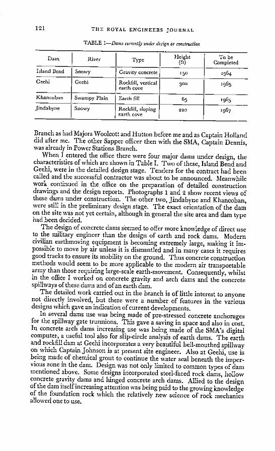
TABLE I-Dams currently under design or construction
Dam River Type Height To beDam River Type (ft) Completed
Island Bend Snowy Gravity concrete 150 1964
Geehi Geehi Rockfill, vertical 300 1965earth cove
Khancoban Swampy Plain Earth fill 65 1965
Jindabyne Snowy Rockfill, sloping 220 1967earth cove
Branch as had Majors Woolcott and Hutton before me and as Captain Hollanddid after me. The other Sapper officer then with the SMA, Captain Dennis,was already in Power Stations Branch.
When I entered the office there were four major dams under design, thecharacteristics of which are shown in Table I. Two of these, Island Bend andGeehi, were in the detailed design stage. Tenders for the contract had beencalled and the successful contractor was about to be announced. Meanwhilework continued in the office on the preparation of detailed constructiondrawings and the design reports. Photographs 1 and 2 show recent views ofthese dams under construction. The other two, Jindabyne and Khancoban,were still in the preliminary design stage. The exact orientation of the damon the site was not yet certain, although in general the site area and dam typehad been decided.
The design of concrete dams seemed to offer more knowledge of direct useto the military engineer than the design of earth and rock dams. Moderncivilian earthmoving equipment is becoming extremely large, making it im-possible to move by air unless it is dismantled and in many cases it requiresgood tracks to ensure its mobility on the ground. Thus concrete constructionmethods would seem to be more applicable to the modern air transportablearmy than those requiring large-scale earth-movement. Consequently, whilstin the office I worked on concrete gravity and arch dams and the concretespillways of these dams and of an earth dam.
The detailed work carried out in the branch is of little interest to anyonenot directly involved, but there were a number of features in the variousdesigns which gave an indication of current developments.
In several dams use was being made of pre-stressed concrete anchoragesfor the spillway gate trunnions. This gave a saving in space and also in cost.In concrete arch dams increasing use was being made of the SMA's digitalcomputer, a useful tool also for slip-circle analysis of earth dams. The earthand rockfill dam at Geehi incorporates a very beautiful bell-mouthed spillwayon which Captain Johnson is at present site engineer. Also at Geehi, use isbeing made of chemical grout to continue the water seal beneath the imper-vious zone in the dam. Design was not only limited to common types of dammentioned above. Some designs incorporated steel-faced rock dams, hollowconcrete gravity dams and hinged concrete arch dams. Allied to the designof the dam itself increasing attention was being paid to the growing knowledgeof the foundation rock which the relatively new science of rock mechanicsallowed one to use.
121

TWO YEARS IN THE SNOWY MOUNTAINS
The drafting of a design report brought my year in the Branch to a close.It was with very great regret that I left. The work, although containinginevitable minor frustrations, was the most satisfying I had ever done. Onthe social side I had made many good friends and learnt a great deal aboutAustralia.
MAJOR CONTRACTS GROUP
Spring in September found my wife and I on the move again, complicatedby the recent arrival of our Australian son and some uncertainty as to wherewe were moving. Our final destination proved to be Eucumbene.
Lake Eucumbene forms the main reservoir for the entire scheme. The damis a 381-ft rock and earth dam forming a reservoir with a capacity of 3,860,000acre-ft. Photograph 3 shows the dam and entrance to the tunnel. Twotunnels already enter the lake (Figure 2), and the third tunnel connecting theSnowy River development with the reservoir is currently being driven. Thisis the 15 mile Eucumbene-Snowy Tunnel. I went to Eucumbene as siteengineer. The contract at Eucumbene came under the SRE at Island Bend.
The tunnel runs from Eucumbene reservoir to the reservoir on the SnowyRiver at Island Bend. It is being driven on three headings, one from Eucum-bene and two from an adit four miles from Island Bend. At Eucumbene thetunnel, a 21 ft horse-shoe, connects with the original diversion tunnel thatwas built when the dam was constructed.
The method of tunnelling used is the well established one of air powereddrills rigged on a rail mounted jumbo incorporating a rear hoist ("cherrypicker") for car passing. The muck car trains pass beneath the jumbo on asmaller gauge track to be loaded by an electrically driven Conway mucker.The mucker is shown in Photograph 4. All the locomotives are diesel. Theexplosive used is ammonium nitrate mixed with diesel fuel supplemented byAN60 gelignite. Fume extraction is by an extractor fan line in the crown ofthe tunnel.
The American contractor, Utah and Brown and Root Sud-Americana Ltd(UBR), was working on a three eight-hour shift six-day week. His best weeklyprogress on the Eucumbene heading was 420 ft, but I believe this has sincebeen raised in better rock to 508 ft. His worst week was one in which noprogress was recorded. This latter case is interesting. A major fault wasknown to cross the tunnel line. On the surface this showed as a very markedstream bed giving reduced cover to the tunnel. There were also several otherrelated faults in the area. The tunnel line had been chosen in the light of anextensive geological exploration to give the best line through the faulted zone.When the tunnel struck the fault it was several hundred feet earlier thanexpected and consisted of a wide zone of crushed and altered granite inter-sected with basalt dykes. Some flows of water were encountered, none severe,but enough to cause the tunnel face and roof to fall away. Excavation byconventional means to the full tunnel profile was impossible, so small tunnelsor drifts, to accept wall plates, were commenced. Photographs 5, 6 and 7show these drifts and give an indication of the type of support required. Thistype of ground continued for over s00 ft and some parts required support asheavy as 8 in x 6 in BSB at 2 ft 6 in centres with 8 in x 6 in BSB invertstruts embedded in concrete. Very little explosive was used in this section.Nearly all the excavation was carried out by hand using pneumatic tools.Once the initial setback was overcome the extremely difficult conditions were
122

Two years in the snowy mountains 1

Two years in the snowy mountains 2

Two years in the snowy mountains 3

Two years in the snowy mountains 4

Two years in the snowy mountains 5

Two years in the snowy mountains 6

Two years in the snowy mountains 7

TWO YEARS IN THE SNOWY MOUNTAINS
tackled very ably by UBR who were able to achieve advances of 40 to 50 ft aweek.
The type of work involved on this contract is fairly typical of the duties ofa site engineer with the SMA. His main duties are to see that the contract isexecuted correctly from the technical aspect, that the standards required areachieved and that correct payment is made for the work done. His successseems to depend chiefly on two points: one is the ability of his team of inspec-tors and surveyors to control the work coupled with his ability to managethem so that they always give of their best; the second is to maintain firm butcordial relations with the contractor, thus ensuring that the contract iscompleted quickly and efficiently.
There are two factors on the financial and quantity control sides of thecontract upon which the SMA insisted, which did a great deal to assist thesite engineer achieve the two points mentioned in the previous paragraph.The contractor was paid at the end of each four-weekly period for the workcompleted in that period. The quantities for the various items were agreedduring or at the end of the period and were exact quantities. Thus, once thequantity bills signed by both parties left the site there need be no futuremeasurement carried out. The second factor was that as each item wasfinished the actual amount was reconciled with the estimated amount and afinal payment made, after which the item was closed. This system meant thatarguments over quantities were settled on the site when the points in disputewere fresh in everyone's mind. This resulted in better relations between thetwo parties and the elimination of a long period of negotiation over finalquantities once the contract was completed. On the debit side these two fac-tors led to a good deal more work for the site staff; but the benefits, includingthe following consequence, far outweighed the extra work.
The inspectors' reports which we used were laid out so that the man-hours spent by the contractor on each task could be extracted. Subsequently,this information was used by the Estimates Branch of CED during the designand planning stages. This information, coupled with the exact knowledge ofthe contractor's earnings and a fair knowledge of wages, enabled a reasonableestimate to be made of costs versus earnings. Apart from the obvious interestof this information, it was very useful when discussing with the contractoralternative ways of carrying out a certain feature to have the costs at one'sfingertips. Best engineering practice sometimes coincided with the cheapestmethod, a convincing argument to a contractor.
SUMMARY
I hope that the contents of this brief article will give some idea of the typeof work performed during a two-year attachment to the SMA. Perhaps it willhelp any RE officer considering applying to decide in favour of going. Heshould not regret such a decision. He will finish his two years with a farwider knowledge of engineering and a much deeper knowledge of his fellowmen. Many of his prejudices and traditional ideas will be shattered and intheir place will have grown a more balanced and genuine set of values. All thisshould help to make him a better RE officer.
In addition he will have learnt a great deal about how a large civilianengineering authority, the SMA, controls a very complex and widely spreadscheme. Much of this learning can be applied direct to military organization
130
THIE ROYAL ENGINEERS JOURNAL
and engineering problems. It also seems likely with the present size of theCorps that large-scale engineering tasks in limited war are likely to have tobe completed by AER units or civilian firms. If this is so it will be very usefulto have officers with some experience of the civilian approach.
ACKNOWLEDGEMENT
Finally I would like to thank the Snowy Mountains Authority for per-mission to publish this article and also for providing the photographs andfigures.
A Field Squadron in EnglandBy MAJOR R. E. WILLIAMS, RE
LOOKING back through past RE Journlals, I have noticed that articles rangeover a wide variety of subjects. Some are purely technical while others arehistorical; some recommend how we should reorganize ourselves as a Corps,and much has been written on operations and emergencies abroad.
Nothing appears to have been written recently about the day to dayactivities and training of a field squadron, which is after all our basic unit; soI thought it might be of interest to describe how 20 Field Squadron, part of36 Corps Engineer Regiment, spent the year 1963. We were based on Maid-stone, and although we were part of the Support Echelon of the StrategicReserve, we were not called to take part in any operations. None the less itwas an exciting year, and for me it dispelled the idea that it is necessary toserve abroad to get any fun out of soldiering. I think the NCOs and Sappersenjoyed it; they certainly developed well.
At the beginning of the year the Squadron was fifty under strength, andwe had just spent a period of four months with only four officers. This wastrying as it meant scratching around to find enough soldiers for any task.One troop had been commanded by a Staff Sergeant who had done the jobadmirably but was beginning to find it a strain. During April 1963 RERecords built us up to full strength, and thereafter things became mucheasier.
We started the year with an Administrative Inspection in January, andfinished it with another in December. The January inspection was held inthe bitter cold weather, and for it we were required to do a drive past invehicles. Snow had to be scraped off the square with a grader, and one of thepractices was done at 14°F; pipes were frozen up throughout the barracks.More I shall not say except we got a good ticket!
For the remainder of January and February the majority of the Squadronwent on upgrading courses either in the Regiment or at the RSME. Therewas specialist training and education. A party of thirty went to the BritishLegion Hut in Aviemore, Inverness-shire, for a week's skiing, where the snowconditions were as good as in Switzerland, although one had to work harderfor one's pleasure. Twelve others joined the Regimental party for winter
131

A FIELD SQUADRON IN ENGLAND
warfare training with the Norwegian Army in Norway. A section of 2 Troop(Captain Thompson) was called out to blast ice on the River Colne to clear apassage for shipping, and we did other snow clearance tasks.
During March the Regiment, consisting of 20 and 24 Field Squadrons,Eastern Command Plant Troop, and various RASC units took part in Exer-cise Hotspur. This was a bridging gallop from Scotland to the Thamesorganized by the CO, Lieut-Colonel G. T. E. Westbrook, OBE, RE. Itwas an ambitious affair lasting three weeks for which preparations in Regi-mental Headquarters had been going on for the best part of six months. Ibelieve 650 letters had been written to land owners asking for the use ofprivate land, and to formations and units demanding vehicles, equipmentand administrative support. Scores of preliminary recces were done.
20 Field Squadron built two heavy ferries on Loch Ryan and we ferriedour transport across to the old military port at Cairn Ryan. This went wellexcept that there was some difficulty navigating the 2-mile passage in a fog.The squadron then moved down to Newark to build a light floating bridgenear the place where cadets from 140 OCTU used to build FBE bridges inthe last war.
Leaving a troop behind at Newark to sort out a farmer's fields which hadbeen dug up during the bridging operation, the remainder of the Squadronwent south to build a light assault raft on the River Crouch. This was afailure due to a variety of reasons; bad weather, a restricted site, childrenmanipulating bridging signs, refusal of outboard motors to work, and ageneral lassitude from a lack of sleep. We got a 3-ton vehicle across the mudat low tide, but this did not really absolve us.
The climax of the exercise was two crossings of the River Thamesnear Henley. Both squadrons built a LFB and two heavy ferries each in turn.Our efforts were much more successful this time. We built our LFB in thepouring rain with an army of pressmen and photographers watching, but Ido not think they got so much satisfaction out of it as we did. The heavyferry operation was done during a wireless silence, and went with less hitchesand heartburn than any of the other operations. There must be a moral heresomewhere.
This was a physically hard exercise carried out in snow, cold and wetconditions. We lived out for the three weeks in bivouacs and a few tents, andwet clothes were dried by wearing them. It gave the Squadron a great senseof achievement. It was the first time we had used the new class 30 trackwaydispensed off a 3-ton vehicle. It is undoubtedly the best bit of equipmentthat the Corps has developed for many a year.
I intend to skip lightly over the early summer because more interestingtraining took place in the autumn. In April we licked our wounds fromExercise Hotspur, and at the end of the month 1 Troop (Lieutenant Fisherand Lieutenant Milsom of the Royal Warwickshire Regiment) went to Canadawith 24 Field Squadron for six weeks, where they constructed a road. 2 Troop(Lieutenant Howgate) and 3 Troop (Lieutenant Bosomworth) did somedemolitions, and spent the best part of a month on the RE Demonstration atGordon Barracks. This was better training than one would at first imagine.
After the RE Demonstration, and the return of 1 Troop from Canada, welaunched forth into an airportability exercise in barracks. We packed ourG 1098 in light-weight boxes, and prepared all the documentation for an airmove. This was useful as it gave the second in command (Captain Garnett),
132

TIlE ROYAL ENGINEEIRS JOURNAL
the SSM, SQMS, Chief Clerk, Troop Commanders and Troop Storemen a
chance to get their heads together to work out facts and figures. It was
followed by some unit self help to improve our accommodation and stores.
We fired our annual range course for ten days, paid another visit to Aviemore
for adventure training, and departed on August block leave.
In the spring the Squadron had been warned for service in Christmas
Island to undertake a POL project and certain works services for six months.
By July we knew most of the details. A total of 148 men were required to fly
out in November and December. A depreservation party was to take vehicles
and plant out of moth balls, and an advance party was needed to start the
POL project off before the main body arrived. The majority of men were
specified tradesmen and there was to be only a small administrative Squadron
Headquarters. The RAF were paying for our services, and each man's pay
and air passage was costed. This all meant that the squadron would have to
be reorganized at some time in the autumn into a POL Troop, Works Troop,
Project Support Troop (drivers, fitters, plant operators, etc) and a Head-
quarters administrative element.Digressing from the story, this necessity to reorganize for works projects
or operations involving a specified number of men for aircraft is unfortunate.
I had had to reorganize a troop to go to British Honduras in 1962, 1 Troop
were reorganized to some extent to go to Canada in April, and further re-
organizations were required for the exercises in the autumn which I will
mention later. I feel that reorganizations have to be accepted in the Strategic
Reserve, but that efforts must be made to build-up the spirit and loyalties of
the new troop quickly. On the other hand, those who order these projects
and employing agencies must not be too rigid in their demands; a Sapper is
a versatile gentleman.During the last two weeks of August we planned for the autumn training
and for Christmas Island in detail. As soon as we had nominated the men
for Christmas Island, we could decide who were to go on the two exercises
in North Africa in November. Not until that was done could we say
who was to go to Stanford Practical Training area and on the bridging
Exercise Marsh Harrier. Nominal rolls were published saying who was
going where, and these were kept up to date as changes occurred. There
were other administrative problems. Each man nominated for the Island had
to have a passport, and he also had to go to the dentist before leaving England
because the nearest one to Christmas Island is in Honolulu. This proved a
formidable task, which disrupted training and was not entirely finished until
early in December. The Army now fights with its teeth, or gums, if it has
not got any; it no longer marches on its stomach.We did not go to a bridging camp this year, but trained in watermanship
on the Medway and bridged in a quarry at Wouldham. Each troop in turn
practised with heavy girder equipment and EWBB. It was interesting to dis-
cover that only about six men in the Squadron had ever done EWBB before.
On 23 September we started Exercise Marsh Harrier, which was set by
the CO for each Squadron. A heavy girder bridging column was made up
from new drivers for 60 Field Squadron, just forming, and vehicles came from
the Reserve Army Pool. With the bridging column we set forth for five days
in the Romney Marshes. Our first bridge, loo-ft DS, was constructed over
the Grand Military Canal, and the whole operation took a night and a day
to complete. This may sound long, but there is a world of difference in using
133

A FIELD SQUADRON IN ENGLAND
a virgin site and off-loading from vehicles, than playing about at some wellworn bridging gap. A lot of Sommerfeld track had to be put down, and thebridge site had to be prepared and levelled during the night, which was noteasy. During the afternoon, 11 in of rain fell and we were within an ace ofthe Coles crane sinking through the Sommerfeld track altogether. Thesecond bridge, 87 ft 6 in SSR, North of Rye, over the River Rother wascompleted more quickly. After an initial mishap with a crane on its side ina ditch everything went smoothly. This bridge was built by LieutenantMilsom who had taken over command of 1 Troop from Lieutenant Fisher.He was in the process of transferring to the Royal Engineers, but had notbeen Gazetted. He is probably the only infantry officer to have been in com-mand of the construction of a heavy girder bridge.
After a few days in Maidstone we hurriedly reorganized into the formationsrequired for North Africa. We departed for Stanford Practical Training Areaon 2 October where the new troops shook themselves down quickly. We dida few days infantry training on our own, and carried out a series of exercisesset by the CO in riot drills, cordon and search and anti-terrorist activities.Regimental Headquarters turned out in force as some particularly belligerentlooking rioters and terrorists, whom we took pleasure in rounding up. Atroop of 24 Field Squadron joined us for a minefield exercise and 2 Troopleft to prepare for North Africa. We laid a mixed minefield about 2,000 ydslong and at places, which had been suitably booby-trapped, each troopbreached at night. This was all standard stuff except for an approach marchacross a bog carrying the required gapping equipment less wire, which pro-duced some interesting results. We finished our time at Stanford with a two-day battle against the 2nd Battalion Coldstream Guards. They put in a seriesof attacks against us and we withdrew along an axis. This was good sport aswell as excellent training. At least two Sappers claimed to have shot theirCO!
2 Troop flew to Benghazi on 13 October for Exercise Quickstrip, takingtheir G 1098 as freight. They were required to construct a light air strip inWavell Barracks for the 14th/20th Hussars. The troop prepared a patch ofdesert with plant and laid PBS. The criteria for the strip was as follows:-
Main stripLength 1,272 ftWidth 48 ftOver runs 200 ft and 150 ft
Cross stripLength 778 ftWidth 48 ftOver runs 200 ft and 150 ft
Both had a camber of 3-ins either side of the centre line. There was also ataxi strip and a fuel point.
There was some trouble over the PBS arriving by ship, so the project wasnot finished in time for the troop to join our other Exercise Longreachfarther along the North African coast. They had in fact to be reinforced.No difficulty was met in laying PBS, and there was an expert, Mr Colquhun,to advise. This exercise was very good value for the troop, especially thetroop Commander who was acting as the contractor to the GWO, and washis own master.
134

TIIE ROYAL ENGINEERS JOURNAL
Exercise Longreach from 1 to 11 November was probably the most inter-
esting one we did during the year. We were flown out to El Adem by the
RAF, and trained in the desert for ten days, using stockpiled vehicles. For
the time we were in the desert we had no administrative support other than
the provision of water and fresh bread. Planning started in August after the
Second-in-Command of the Regiment (Major Moss) had visited various
Headquarters round the Mediterranean. Thereafter we reverted to paper
work, and had to deal with fifteen different formations and Headquarters.
The Regimental Quartermaster (Major Whitehead) took out our advance
party on 14 October and set up a base camp on the shores of the sea at
Bomba, 90 miles West of Tobruk. He took over vehicles from 3rd Division
after their Exercise Triplex West, and laid in stocks of food and POL. Plant,
engineer stores and some wireless sets came from Cyprus and Malta by sea.
It was fortunate that the Quartermaster led this advance party as they met
difficulties which required a strong arm to sort out.The Squadron was depleted by 2 Troop in Benghazi, and 3 Troop who
were going on embarkation leave for Christmas Island, so we were reinforced
by a troop from 24 Field Squadron. We flew out in four Argosies from RAF
Benson and took with us 15,000 lb of freight, 1,000 lb of explosives and a
Michigan Light Wheeled Tractor (15,694 lb) in the aircraft. The Michigan
was delayed at Malta, but duly arrived a few days late and the driver brought
it the 90 miles up the coast road on his own. I believe this was the first time
a Michigan has been carried by an Argosy for such a long distance.
Our main task was to improve a desert track from a place called Umm Er
Rezum to Umm Hafien for the benefit of local villagers, whose patience had
been stretched by previous exercises in the area. We used the plant and
explosives on this. We did a series of desert patrols in Landrovers to practice
navigation and to search for water, culminating in a two-day trip of 120
miles. In looking for water we were guided by Major F. Moseley's article in
the RE Journal of June 1963, called "Fresh water in the North Libyan
Desert". Although we did not find much in the places he suggested,
primarily because we did not have the proper search or well boring equip-
ment, we did develop a source sufficient to supply a troop living near it. We
finished with a desert march. The stockpile vehicles worked well, and with
some improvization we kept the plant going. I regret though that it will have
taken more than improvization to repair a compressor belonging to CRE
Cyprus which careered down a wadi bed after shedding its front wheels
whilst on tow. My humble apologies to him!We left the shores of the Mediterranean, and returned to England on a
bleak mid-November evening with a 70-knot wind gusting across RAF
Benson runway. 2 Troop from Benghazi joined us for the return flight, for
which we had six Argosies. Lieutenant Milsom and a small party remained
behind to clean up the vehicles and return stores to Cyprus.
Exercise Longreach was expensive in money and effort, but it was well
worth doing. The more training we get like this in the Corps the better;
Sappers thrive on it.On our return from North Africa there was an intensive period of cleaning
up and preparing for the administrative inspection. The final reorganization
for Christmas Island took place on 18 November, and the three parties left
by air on the dates shown in the programme. I saw the main body off in a
Britannia of British United Airways fom Stanstead airport shortly after
135

CROMWELL'S RIVER CROSSINGS
midday on 30 December, having handed over to Major Negus. So ended1963.
I do not have any profound conclusions to make, and readers may drawtheir own. This is the story of one field squadron in peace time in England,but I should like to say three things:
a. I definitely favour the regimental system of grouping field squadrons.I have not said much about Regimental Headquarters as this is primarily thestory of 20 Field Squadron, but they did the majority of the forward planningfor the major exercises. It would not have been possible to carry out nearlyso much collective training as an independent field squadron under conditionsprevailing in England at the present time.
b. At the end of the year we were in a better state of training than we wereat the beginning of it. The soldiers had matured, especially the NCOs, forwhom there had been a lot of promotion even to the extent of twice in theyear for some of them.
c. I hope that the taxpayer had his money's worth.
Cromwell's River CrossingsBy LIEUT-GENERAL SIR CHARLES KING, KBE, CB
IN Buchan's Life of Cromwell the author gives a few glimpses of operationsinvolving crossings of large waterways. These operations were obviously ofsome magnitude and they invited further study. The County Library pro-duced several books covering the operations in general, but none gave anydetailed technical information. Eventually the standard work-Fritz Hoenig'sOliver Cromwell-was produced in three massive volumes and equally massiveGerman.
It was clear from the bibliography in his book that Hoenig had consulteda very large number of the original documents. Unless more informationhas been unearthed in the last fifty years, it is unlikely that any further de-tailed information is available. With true Teutonic thoroughness, Hoeniggives innumerable references to Cromwell's own letters. The translation ofCromwellian English into modern German may well lead to imperfect render-ing. The re-translation into English by one whose German is rusty in theextreme could produce a result differing widely from the original version.This sketch makes no pretence to historical research. It takes Hoenig's wordas correct without any check on original documents for which the writerhas no opportunity or knowledge.
The description of the operations gives very limited technical information,but it is sufficient to arouse a sharp curiosity of the ways and means by whichthese difficult operations were successfully carried out.
Cromwell undertook three major crossings, excluding the invasion ofIreland which falls into a separate category and is not discussed here.
136

*
137 TIIE ROYAL ENGINEERS JOURNAL
The three operations were:-(i) The crossing of the Humber at Hull.
(ii) The crossing of the Firth of Forth at Queensferry.(iii) The crossing of the Severn at Worcester.
These were opposed crossings and by any standards major operations.
Cromwell's own letters were terse in the extreme. In his letter of 21 July1651 to Speaker Lenthall he says, "We were directed (by God) to send aparty to get us a landing on the Fife coast by our boats." After this comment,Cromwell takes it all for granted.
In another letter to the Speaker written from "Near Worcester 3 September1651 (10 at night)", Cromwell starts by saying he is so weary and scarce ableto write. This is hardly surprising as he had been fighting all day "as stiff acontest for four or five hours as ever I have seen". Cromwell's report on thebridging operations is "We built a bridge of boats over Severn between itand Teme about half a mile from Worcester and another over Teme withinpistol shot of our other bridge".
There is some difficulty in estimating correct numbers. Hoenig complainssomewhat peevishly that he has found discrepancies even in contemporaryletters. The Parliamentary Army was organized in regiments of horse andfoot regiments nominally 1,000 strong. Each regiment appears to have hadten squadrons or companies of 100 strong. At times, these figures were liableto great variations as Hoenig complains. Field guns are mentioned, butinformation on the organization or establishment is missing. One of the mostremarkable omissions is the apparent absence of transport for food andammunition.
THE CROSSING OF TIIE HUMBER
In August, 1643, part of the Parliamentary Army was shut up at Hullunder the command of the older Fairfax. Cromwell was collecting a new armyround Cambridge. He advanced into Lincolnshire, drove back the Royalistsand joined up with General Willoughby's force. He then turned his attentionto the problem of getting Fairfax's army out of Hull. The Royalist Armyinvesting Hull was of superior strength to Cromwell's forces. Cromwelldisposed his forces in a semi-circle round Saltfleet, a town on the Lincoln-shire coast some thirty miles from Hull.
On 26 September 1643 Cromwell and Willoughby "climbed" into a boatat Saltfleet and set out for Hull, where they arrived safely on the same day.Hoenig makes a remark that, even with a favourable wind and tide, it was aday's sail from Saltfleet to Hull. Cromwell discussed ways and means withFairfax. "So many boats were available in Hull that all the Cavalry couldembark in one trip. A successful issue was to be hoped." Thomas Fairfaxagreed at once, but his brother hesitated for some time. It was eventuallydecided that D-day should be the 27 or 28 September. On one of these days(dates are vague) 21 Squadrons of Cavalry and Dragoons were embarked.The fleet was dispatched and arrived safely at Saltfleet and disembarked.The boats then sailed back to Hull. The Royalist Cavalry tried to interferewith the landing but the disembarkation was safely accomplished. Cromwellconcentrated his army early on the 29 September.
There are many gaps in the story. To embark twenty-one Squadrons-nominally 2,100 men and horses-in the face of any opposition is a formid-able task and there are many details one would like to know.

CROMWELL'S RIVER CROSSINGS
CROSSING OF THE FIRTH OF FORTH
In December 1650 Cromwell had made all the necessary arrangements forthe resumption of hostilities against the Royalists under the command ofGeneral Leslie who was at Stirling. Cromwell realized that there was littlechance of manoeuvring him out of his strong position. Cromwell asked theauthorities in London for a part of the Navy. He specially asked for largeflat-bottomed boats to enable him to carry out a landing on the South Coastof Fifeshire, thus turning his opponents' position. Unfortunately Cromwellwas sick for four months and it was not until March 1651 that he was able toproceed with his plans. It is interesting to note that Cromwell at no timedivulged any of his plans even to the highest authorities. No trace, or even apointer, could be found in any letters to his wife, his family or even to theCouncil of State in Parliament. He reported his action only when he hadstarted to carry out his plans.
In June 1651 Cromwell appreciated the situation and amongst variouspossibilities was this item: "In case of failure (ie to cut off the Stirling forceby land) to cross the Firth of Forth. In this purpose, specially designed boatswould be necessary." General Deane, the Fleet Commander, had broughttwenty-seven such boats to Cromwell. A further number had been found inthe Firth of Forth and had been captured from the Scots (these are hardlylikely to be special design). By the middle of June, the requirements of boatshad been met, though numbers are not mentioned.
Cromwell concentrated his army of 25,000 men on the Pentland Hills.Offensive operations against Stirling were undertaken but without anysuccess. Cromwell was convinced that the crossing at Queensferry was theonly solution.
The problem was formidable: the proximity of Leslie's force at Stirling,the fortification on the Fife coast, the necessity for surprise, the state of thetide. All these problems were reproduced in far greater measure in 1944.Cromwell decided to despatch the flotilla at night from Queensferry in orderto carry out the actual landing in the early morning. Cromwell appointedGeneral Lambert in command and put at his disposal three Regiments plusfour companies of foot and three Regiments of cavalry-a total of 6,000 men,assuming that the units were up to strength. At the same time, a force underColonel Overton, consisting of one Regiment and four companies of foot and,one Regiment of cavalry, marched off on 17 July from Queensferry to joinGeneral Lambert's force which remained in a position of readiness.
Colonel Overton had the task of returning to Queensferry as dusk wasfalling, to embark in the boats and to sail as advance guard. A formidable taskfor tired men. Cromwell remained with the rest of his army, demonstratingagainst Leslie's force in order to divert his attention from the main operation.
Little is known about weather conditions, but it appears that they werenot unfavourable.
There were sufficient boats for the advance guard to embark in one flight.Incidentally, they carried spades and shovels to dig in immediately on landing.Coastguards discovered the approach of the flotilla and small arm fire wasexchanged. Gun fire is mentioned but appears to have had little effect.Without serious opposition, the force landed. The infantry at once advancedto attack Inverkeithing, which was evacuated by the defenders who aban-doned their guns and weapons. The force formed a bridgehead at the North
138

TIIE ROYAL ENGINEERS JOURNAL
Ferry with a protecting line of entrenchments. After disembarkation theflotilla returned to Queensferry where Lambert reported his success toCromwell. Cromwell immediately ordered all to cross and by the evening ofthe 18th Lambert with three Regiments and four companies of Foot andthree Regiments of Horse were at Inverkeithing. No mention is made ofcasualties.
BRIDGING TIIE SEVERN
In 1651 Prince Charles (afterwards Charles II) landed on the West Coast ofScotland and raised an army. He decided to invade England in the ratherforlorn hope of obtaining support from his sympathizers. He marched southon the western side of England, while Cromwell hurried down the easternside to overtake. He caught up with the Scots at Worcester and was facedwith the problem of crossing the Severn in order to bring them to battle.The Severn is here about 100 metres wide and makes a formidable obstacle.Some ll miles south of Worcester, the River Teme joins the Severn. TheTeme was bridged at Powick, some two miles below Worcester. This was inthe hands of the Scots. In addition, there was a bridge over the Severn atUpton, some eleven miles south of Worcester. This bridge was destroyed bythe Scots, who were occupying a position covering the site.
In spite of the destruction, a beam was found long enough to bridge thegap. A party of Lambert's Cavalry arrived and dragged the beam over thegap and crossed "sitting astride the beam". They then replaced the bridge,crossed with their horses and took up a covering position, reporting theiraction to General Lambert. He sent help and the Scots were driven back.Hoenig comments, "This glorious and forever outstanding cavalry actiontook place on August 29th."
Cromwell decided that Upton was too far from Worcester, as it needed aday's march to cross the river at that point. He, therefore, formed a bridgingtrain, presumably from the material which Lambert had collected. His inten-tion was to bridge the Severn just south of the junction of the Teme with theSevern.
Early on 3 September Cromwell's dispositions were complete, and hestarted the work on the bridge, which "proceeded rapidly because of thesecareful preparations". At midday on the same day, the work was completed.Hoenig comments, with every justification, "Before this a similar operationhad never been carried out with such rapidity."
Fairfax had been ordered to bridge the Teme as soon as the bridge overthe Severn was complete. For this purpose, special boats had been prepared.They were hurried up to the site. Owing to various difficulties, they onlyarrived on site at 3 pm, but the bridge was completed by 5 pm on the sameday. The battle began at 5.45 pm led by Fairfax over the Teme bridge.
CONCLUSION
There are so many gaps in the information. The ineffectual action of theRoyalist Army seems inexplicable. On the technical side, it would be inter-esting to know many things. How did the horses embark and disembark?There must have been great congestion in the boats, which presumably weretowed. The design of the bridge over the Severn would be interesting, andmany other problems.
Perhaps this short sketch may stimulate curiosity for proper research, oreven for a trial run by a unit instead of a Bridging Camp.
139

Repair ofLight Alloy Bridging Equipment
"Here's Metal More Attractive" (Hamlet Act 3 Sc. 2)
By COLONEL W. G. A. LAWRIE, MA, AMICE
THE object of this paper is to discuss the use of aluminium alloys for militarybridging equipment and to suggest lines of action which should be followedif full use is to be made of their potentialities. The views expressed are myown, and not necessarily Army policy.
HISTORICAL BACKGROUND
"Bailey Bridging made an immense contribution towards final victory inWorld War II. As far as my own operations were concerned with the EighthArmy in Italy and with the 21st Army Group in North West Europe, I couldnever have maintained the speed and tempo of forward movement withoutlarge supplies of Bailey Bridging." Montgomery of Alamein,
Field Marshal, CIGS.
Immediately after the last war the tendency was for military loads to in-crease. The obvious temporary solution was to strengthen the Bailey Bridge,but as various heavier expedients were introduced they imposed an ever-increasing strain on transport and manpower.
At the same time the introduction of the nuclear weapon demanded smallerconcentrations of troops and vehicles, and fulfilment of our limited warcommitments necessitated the development of air-portable equipments. Thedesigners naturally turned to aluminium.
The outstanding property of aluminium is its lightness; its specific gravityis only about one-third that of steel, zinc or copper. In its pure state it haslittle strength, but the addition of small quantities of other elements such ascopper, magnesium, manganese or zinc produces alloys which are comparableto mild steel. This gives a strength/weight ratio very much in favour ofaluminium, but at the same time its other properties may be affected. Strongeralloys are correspondingly more difficult to manufacture, and in some casestheir corrosion behaviour is less satisfactory.
METALLURGICAL PRINCIPLES
Before we can understand the reasons for the selection of a particularalloy for use in a military equipment, or appreciate the difficulty of main-taining it in a serviceable condition, it is useful to know something about themetallurgical principles involved. To begin with, an alloy is actually a solidsolution. Just as an iceberg is a solid solution of salt in water, so we canhave a solid solution of copper or various other elements in aluminium.Furthermore, copper and aluminium also form the chemical compoundCu Al2 which may be present in the alloy. This is known as an intermetallicconstituent; other elements may react in a similar way.
The various changes of state which take place when an alloy is heated areillustrated in the Aluminium-Copper Equilibrium Diagram (Fig 1). This
140

TIIE ROYAL ENGINEERS JOURNAL
shows that for any given percentage of copper the structure of the alloy willchange with variations in temperature.
For example take the case of an alloy containing 3 per cent of copper. Thestate of the alloy at different temperatures will be as follows:-
Over 650°C The alloy is in a completely liquid and homogeneous state-a liquid solution of copper in aluminium.
650°-600°C As the alloy cools it becomes a pasty mixture of liquid andsolid solutions until it solidifies completely at 600°.
600°-460°C As the temperature falls some of the copper is precipated,forming Cu Al2
below 460°C The alloy is now a solid solution interspersed with crystalsof Cu Al2.
When the alloy is heated again to a temperature between 460° and 600°the Cu Al2 dissolves into the solid solution, and if it is suddenly quenched inwater, some of this Cu Al2 remains in solution. This artificially enrichedsolid solution is unstable and excess Cu Al2 tends to precipitate. A similarprocess can take place when other elements are alloyed with aluminium andthe possible variations are many indeed, using different percentages ofdifferent metals. However, the underlying principle is the same-it is thepresence of excess intermetallic constituents dispersed throughout the solidsolution which sets up strains within the crystalline structure of the alloy and,thereby, gives it its extra strength and hardness.
HEAT TREATMENT
When we talk about the heat treatment of an aluminium alloy we refer tosolution treatment, precipitation treatment and full heat treatment. Solutionheat treatment is the process of heating the alloy to a certain temperature,then suddenly quenching it. In order to obtain maximum strength thegreatest possible amount of intermetallic constituents must be held in solidsolution. This will be achieved when the solution treatment temperature isas high as possible without exceeding the solidus. In some cases precipitationof excess intermetallic constituents takes place at room temperature. Thisprocess is termed natural ageing. In other cases the temperature has to beraised to between 150 0C and 200°C. This accelerated form of ageing is calledprecipitation treatment. Maximum strength is obtained by prolonged ageingat room temperature rather than by rapid ageing at high temperature. Ifheating is carried on too long or at too high a temperature the material "over-ages" and starts to become softer again. Full heat treatment of course meansthat both solution treatment and precipitation hardening are carried out.Heat treatable alloys are those which are capable of being strengthened byone or both of these processes.
Some alloys are described as non-heat treatable. They do not respond tothe processes described above but can be strengthened by work-hardening.Cold working of any metal by rolling, drawing or pressing disrupts the crystalgrains, wlich are of regular atomic structure, into a large number of smallcrystals and crystal fragments. At the same time the number of planes ofeasy slip diminishes and resistance to plastic flow of the metal under stressincreases. The metal has now been work-hardened. It can be annealed byheating it to a particular temperature, wlhen the crystals reform, and themetal is restored to a soft condition capable of further cold working.
141

REPAIR OF LIGHT ALLOY BRIDGING EQUIPMENT
°C Liquid solution of copperin aluminium./
700LIQUIS
IMixture of liquid00 -and solid
solutions
Solid solution of copper
;Xo in aluminium
400
Solid solution of copper in
30 aluminium interspersed with3 / particles of Cu A12
200
100
1 2 3 4 5 6
Copper content (% by weight)
Fig.l. Aluminium-Copper Equilibrium Diagram
LIMITATIONS AND ADVANTAGES OF ALUMINIUM ALLOYS
It is evident that aluminium alloys are liighly susceptible to temperature
changes, unless they are used in the fully softened or annealed condition. A
rise in temperature above a critical point may completely alter their physical
properties. Strength lost in this way can only be restored partially or very
slowly. This is the first limitation to be borne in mind when considering the
manufacture or repair of military bridging equipment.At this point it is appropriate to consider another limitation to which
aluminium alloys are subject. Certain alloys are highly susceptible to electro-
lytic corrosion, which may be intensified by contact between dissimilar
metals, including different aluminium alloys, and is often intercrystalline in
character. This is especially marked when the metal becomes wet by moisture
containing salt, acid or any other electrolyte. When dissimilar metals are in
contact one metal will dissolve preferentially; it is said to behave anodically
and is termed an anode, the other metal of the pair being designated the
cathode. The combination of anode and cathode constitutes a galvanic
couple. A variation of mechanical properties brought about by different
R.E.J.-F
142
THE ROYAL ENGINEERS JOURNAL
degrees of mechanical working of the surface of the metal can also give riseto electro-chemical dissimilarity.
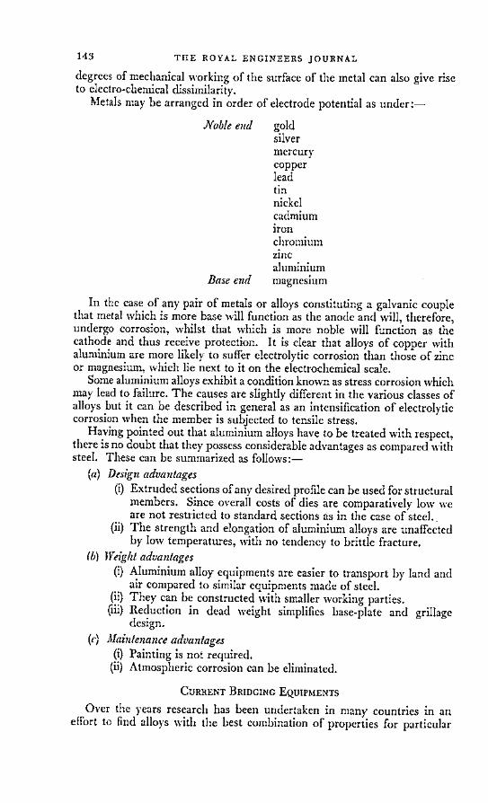
Metals may be arranged in order of electrode potential as under:-
Noble end goldsilvermercurycopperleadtinnickelcadmiumironchromiumzincaluminium
Base end magnesium
In the case of any pair of metals or alloys constituting a galvanic couplethat metal which is more base will function as the anode and will, therefore,undergo corrosion, whilst that which is more noble will function as thecathode and thus receive protection. It is clear that alloys of copper withaluminium are more likely to suffer electrolytic corrosion than those of zincor magnesium, which lie next to it on the electrochemical scale.
Some aluminium alloys exhibit a condition known as stress corrosion whichmay lead to failure. The causes are slightly different in the various classes ofalloys but it can be described in general as an intensification of electrolyticcorrosion when the member is subjected to tensile stress.
Having pointed out that aluminium alloys have to be treated with respect,there is no doubt that they possess considerable advantages as compared withsteel. These can be summarized as follows:-
(a) Design advantages(i) Extruded sections of any desired profile can be used for structural
members. Since overall costs of dies are comparatively low weare not restricted to standard sections as in the case of steel.
(ii) The strength and elongation of aluminium alloys are unaffectedby low temperatures, with no tendency to brittle fracture.
(b) Weight advantages(i) Aluminium alloy equipments are easier to transport by land and
air compared to similar equipments made of steel.(ii) They can be constructed with smaller working parties.
(iii) Reduction in dead weight simplifies base-plate and grillagedesign.
(c) Maintenance advantages(i) Painting is not required.(ii) Atmospheric corrosion can be eliminated.
CURRENT BRIDGING EQUIPMENTS
Over the years research has been undertaken in many countries in aneffort to find alloys witl the best combination of properties for particular
143

REPAIR OF LIGHT ALLOY BRIDGING EQUIPMENT
purposes. In many cases military requirements have formed the spearheadbehind which wider civilian applications have followed. Research intovarious aspects of aluminium alloys still continues. One difficulty is that thereis no international code of design or even of nomenclature. In June 1963 asymposium on "Aluminium in Structural Engineering" was held in London.It was attended by eminent professors from America, Germany, Belgium andSwitzerland as well as British experts. They were all carrying out advancedresearch in their own countries but lamented the difficulties of co-operationimposed by the absence of a common code of practice.
Thus when designers at the Military Engineering Experimental Establish-ment (MEXE) were asked immediately after the last war to design a newfamily of bridging equipments they turned to aluminium alloys which wereknown in this country or in the United States. The results of their efforts,which included both steel and light alloy components, are listed below:-
I Design Prototype Under IntroducedEquipment period ready trial into Service
Heavy Girder 1946-49 1950 1951-53 1954Bridge
Light Floating 1946-50 1951 1952 1956Bridge
Heavy Ferry 1946-51 1952 1954 1957
Heavy Floating 1951-54 1955 1956-58 1962Bridge
REPAIR TECHNIQUES
Some of these equipments have been in use for nearly ten years and haveinevitably been damaged on numerous occasions by accident or throughnormal wear and tear. Engineer workshops at all echelons have improvisedand developed a variety of techniques to keep them operational, although noofficial repair manuals have yet been issued, and even the provision and re-plenishment of essential maintenance spares has never been satisfactory. Inorder to put right this situation the RE Repair and Maintenance AdvisoryTeam was authorized in 1963 and they have already drafted several repairpamphlets for issue in 1964. RERMAT have a difficult task if they are tocatch up with ten years back-log of work as well as keep abreast of newdevelopments. They have, however, the advantages of direct access to MEXEdesign staff and a considerable body of user experience in the field and inworkshops on which to base their doctrine, both in regard to current equip-ments and those still in the design stage.
It is worth examining the basic repair techniques which have been evolvedin the last ten years, and which are described in detail in the new repairpamphlets, including their particular application to each equipment.
(a) Emergency repair kits
Special kits are supplied with all floating equipments containing variousitems which can be applied by any intelligent Sapper to stop them sinking.They include various sizes of bung which can be used to plug bullet holes,
144

TIIE ROYAL ENGINEERS JOURNAL
screw-on patches and a supply of epoxy putty (also called epoxy dough).Holes up to 4 in diameter in wood, steel or aluminium alloy hulls can bcrepaired with epoxy putty. This consists of epoxide resin with an inert fillerto which a hardener is added. After 8 hrs the filling is completely hard andcan be sanded and painted, but in an emergency the pontoon can be re-launched in 2 hrs. Holes larger than 4 in across can be repaired by buildingup layers of epoxide resin and glass fibre or wire gauze on a backing of lightalloy sheets. This method has been used successfully under certain circum-stances to make good damage to structural members. Epoxy putty which isabrasion-resistant can be used for building up badly worn extrusions as longas structural strength is not required.
(b) Bolted or riveted metallic patches
These are used for larger holes and provide more permanent repairs.They are much slower to execute and require a certain amount of skill andknowledge to design and apply. Standard rivets are available in variousalloys, with different types of head, and in different lengths and diameters tosuit different thicknesses of plate. There are a large number of proprietaryfastenings on the market, all of which require more or less special tools anda wide range of rivets to cover every case.
In an emergency "fitted" bolts can provide a simple method of repair.Holes in patch and plate are hand drilled to a diameter slightly less than thatof the bolt, which is then driven in, swaging the holes to the exact diameter.
There are also various patent types of bolt which have been used forbridging repairs. "Huckbolts" consist of a bolt with a protruding tail andcollar. A special pull-gun applied to the tail causes the work to be tightlyclenched together until the collar is swaged into lock grooves. The tail of thebolt then breaks off. "Jo bolts" are used where only one side of the work isaccessible. They consist of a high-tensile steel bolt and nut and a stainlesssteel sleeve. The whole assembly is inserted into the hole and the specialdriving tool causes the sleeve to be drawn up hard against the blind side ofthe work. At a predetermined torque the tail of the bolt breaks off flush withthe head of the nut on the outside of the work.
Self-tapping screws provide a satisfactory method of fixing patches, usingthe minimum of tools, provided there is no possibility of independent move-ment.
All these methods are being tested by RERMAT in order to compare theirefficiency under controlled conditions. But their introduction as standardmethods of repair would involve the scaling and cataloguing of all thefasteners and special tools, and the holding of spares at all echelons in thesupply chain.
(c) Welding
Modern techniques and equipment permit the safe welding of certainalloys provided the members involved are not stressed beyond 8 tons persq in. The article entitled "Fusion Welding of Aluminium Alloys" by MajorD. L. Jones, RE, which appeared in the RE Journal for June 1961, gave a veryclear outline of the methods and equipment used. Since then the LYNX 500MIG welding set and the QUASI-ARC SIGMETTE light welding set havebeen authorized for the RSME and Engineer Base Workshops at home andoverseas, and tradesmen will be acquiring experience in their use.
1 a 0
145

REPAIR OF LIGHT ALLOY BRIDGING EQUIPMENT 146
THE PROPERTIES OF DIFFERENT ALLOYS
This experience is essential because of the many complications introducedby the physical properties of aluminium alloys. Although their meltingpoints are low (520°-650°C) their high latent heats require welding tempera-tures which destroy the extra strength obtained by heat treatment. Inaddition, their high conductivity is liable to cause a rise in temperature overa much wider area than in the case of steel. Fig 2 shows that, although theweld was only j-in wide, a 6-in strip of metal has been seriously affected.Apart from loss of strength, ductility in the overheated region is reduced,which may cause cracking on cooling.
120
VickersDiamondpyramid 100hardnessnumber
8X
l 3 2 1 Weld) 1 2 3 4 inches
PigJ2; Variations in hardness across a welded alloy plate
(The original alloy was naturally aged after solution treatment andthe hardness was teated four days after completion of welding).
Aluminium alloys also expand twice as much as mild steel on heating, soto avoid buckling, allowance must be made for expansion during welding andsubsequent shrinking.
Many of these difficulties would be eliminated if "eutectic" or low tem-perature welding could be applied to the alloys used in military bridges.This process utilizes the phenomenon that certain alloys melt at much lowertemperatures than either constituent metal. For example copper melts at1083°C and aluminium at 660°C, but the melting point of an alloy containing33 per cent copper and 67 per cent aluminium is only 548°C. Unfortunatelythis particular alloy has no military application and no way has yet beenfound of using this principle to weld high strength aluminium alloys attemperatures low enough to avoid weakening.
Some alloys quickly regain much of their strength if the appropriate heattreatment is applied. In the case of Constructal 21/51 for example, the parentmetal starts with a 0.2 per cent proof stress of 16 to 23 tons per sq in, de-pending on the heat treatment it has received. The strength near a weldfalls to 6 to 8 tons per sq in. After 7 days the strength recovers to 9 to 10tons per sq in, and after 30 days it reaches 12 to 14 tons per sq in. Butunder operational conditions it will not be possible to wait for natural ageingto take place. A small electric blanket is now being developed which wouldmaintain a temperature of 100°-120°C in the welded region, giving a strengthof 11 to 13 tons per sq in in 24 hrs.
l

THIE ROYAL ENGINEERS JOURNAL
The proof stress mentioned above is taken to be the point in the stress/strain curve where plastic flow is commencing. It sets the limit to the ulti-mate load a structure can withstand. If working stresses during the designstage are based on a 0.2 per cent proof stress, the allowable permanent dis-tortion is limited, thus ensuring interchangeability of components. 0.2 percent proof stress is found from the stress/strain curve by drawing a lineparallel to the straight line portion of the curve through a point on the strainaxis representing an extension of 0.2 per cent (see Fig 3).
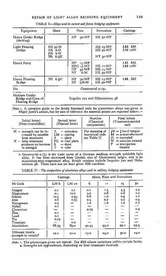
The welder's task is complicated by the fact that current and forthcomingbridging equipments include about twenty different specifications of alloy,each of which may be affected by heat in a different way (see Table I).
I ISTRESS -I i \
.2% Ultimate Tensile
proof stress Strength
limit
II!/
STRAIN
Fig.3 Typical stress/straindiagram for aluminium alloy
THE PROBLEM
We have a large number of aluminium alloy equipments made up of avariety of different alloys and scattered throughout the world. They havebeen damaged and repaired in an ad hoc manner from time to time, butno clear policy exists to define the repairs that may be carried out at each
147
REPAIR OF LIGIIT ALLOY BRIDGING EQUIPMENT
TABLE I-Alloys used in current andfuture bridging equipments
Equipment Sheet Plate Extrusions Castings
Heavy Girder Bridge HP 30-WP HE 30-WP(decking)
Light Floating HS 30-W HE I 5 -WP LM 6MBridge NS 6-0 HE 30-WP LM loW
NS 6-WNS 6-iH HT 30-WP
Heavy Ferry HP 15 -WP LM 6MHPC 15-WP HE Ii-WP LM loWHP 3 0-WP HE I5-WPNP 6-M HE 30-WP
Heavy Floating NS 6-IH HP 30-WP HE I 5-WP LM 6MBridge NP 5 /6-M HE 30-WP
M2 Constructal 21/51
Medium GirderBridge and Class 16 Impalco 720 and Hiduminium 48Floating Bridge
Notes i. A complete guide to the British Standard code for aluminium alloys was given inMajor Jones's article, but for ease of reference the essential points are repeated below:-
Number Final lettersInitial letter) Second letter (Chemical (Treatment carried
(Heat-treatability) (Physical form) composition) out)
H = strength can be in- E = extrusion For meaning of ¼H = ¼ hard tempercreased by suitable LM = casting numerical code M = asmanufacturedheat treatment P = plate see Table II O = annealed
N = heat treatment PC = clad plate W = solution treatedproduces no increase S = sheet P = precipationin strength T = tube treated
2. Constructal 21/51 is the trade name of a German medium strength weldable lightalloy. It has been developed from Unidal, also of Continental origin, and is analuminium-zinc-magnesium alloy. British versions include Impalco 720 and Hidu-minium 48. These have not yet been given BSS numbers.
TABLE II-The composition of aluminium alloys used in military bridging equipments
Castings Sheet, Plate and Extrusions
BS Code LM 6 LM o 6 11 15 30
Copper o.1 o.1 o.l 1.5 4.3 I.oMagnesium o.1 l 1.0 5.0 o.8 o.8 ..oSilicon 12.0 o.35 o.6 I.o 0.9 I.oIron o.6 0.35 0.5 0.7 0.7 0.5Manganese 0.5 - 1.o i.o 1.2 0.7Nickel o. - - - - -Chromium - - 0.25 - - 0.3Zinc o. - - - - -Lead o. - - - - -Tin 0.05 - - - - -Titanium - 0.2 - - - -Aluminium 86.35 89.0 92.55 95.0 92. 95.5
Ultimate tensile 12.0 20.0 17.0 24.0 30.0 19.0strength in tons/in-
Notes i. The percentages given are typical. The BSS allows variations within certain limits.2. Strengths are approximate, depending on heat treatment received.
148

TIIE ROYAL ENGINEERS JOURNAL
echelon in peace or war, nor, if welding is to be one of the authorized methods,have we the equipment or trained Sappers to carry it out in the field.
It is suggested that the problem be considered from several angles and inthe following order:-
(a) Organization-How will the equipments be deployed in operations?What damage capable of repair is likely to occur? What are the correctmethods of repair and what organization and equipment is required to enablethese repairs to be carried out?
(b) Training-How many skilled tradesmen are required to implement thedecision on organization? What training is required by personnel of fieldsquadrons, field park squadrons and RE base workshops?
(c) Spares-How does the fact that a particular component can, or cannot, be repaired affect spares scaling? How can we ensure that spare partsare ordered for the planned life of an equipment during the main productionrun?
PROPOSED ORGANIZATION
It is safe to assume that in any future war whether in Europe or elsewheremovement will be an even more critical factor than in the past. There willbe no large dumps of bridging equipment from which replacements can bedrawn, nor will it be feasible to switch equipment from one front or routeto another. This means that a formation will have to make do with its originalallocation of bridging for each phase of the war, whether it is a matter of daysor months. It will, therefore, be vitally important to keep equipment service-able and to repair damage immediately.
From what has been said already it will be evident that many componentsare impossible to repair under field conditions. Welding temperatures mightreduce the strength of a stressed member in a particular alloy to a dangerousfigure or cause unacceptable distortion. Such items must be covered by pro-viding an adequate proportion of sub-assemblies and component spares.This applies to nearly everything in the nature of a girder or strut. Skins ofpontoon hulls, which are the items most susceptible to damage and mostdifficult to transport, can often be repaired fairly easily. Every field squadronengaged in bridging operations should carry the necessary stores and everyfield squadron NCO should be trained to use them.
There will, however, be cases where more extensive repairs are required.Should we go for riveted or bolted patches, or welding or both? In spite ofthe inherent difficulties involved I believe we should decide on welding, forfollowing reasons:-
(a) By the time any decision is implemented more and more equipmentswill be coming into the Service made of "weldable" alloys such as Con-structal 21/51.
(b) There is no repair that can be carried out by patching that cannot bedone quicker and more efficiently by welding.
(c) Light alloy welding equipment will be needed for the repair of otherengineer equipments besides bridging-e.g. piping and trackway. It can alsobe used for welding ferrous metals.
In short the light alloy welder is the tradesman of the future. The Corpsshould realize this and take appropriate action now.
m �� w-
149

REPAIR OF LIGIIT ALLOY BRIDGING EQUIPMENT
In 1961 it was suggested and agreed that "forward repair teams" shouldbe established in BAOR. They were to be equipped with a formidablearray of kit including:-
Electric sawing, shearing and drilling tools.Portable welding set with generator and alternator.Pneumatic drilling, grinding and riveting tools.Hand riveting tools with a full range of rivets, bolts, screws, etc.Light alloy sheets, plates and extrusions.Epoxide resins, glass fibre and wire gauze.
It has taken so long to obtain approval and assemble the equipment thatthe first team will only be ready to operate on an experimental basis this year.Even then I do not think that this will be found to be the best answer. Giventhe right tradesmen and tools the field park squadrons should accept re-sponsibility for the field repair of equipments being used by their formations.The thirty or forty different emergency repair kits now in existance, all ofwhich have had to be scaled and catalogued, should be augmented or re-placed by bulk stocks of items such as epoxide resins, glass fibre and alloysheets to be held by the field park squadrons in the same way as they heldsolder or glue. In general, then, no special organization is required, but thefield park squadrons must be brought up to date in tools and tradesmen, andah hoc repair teams must practise moving rapidly from one bridging site toanother across country or by helicopter.
The amphibious squadron is a special case. Their vehicles are not madelike Meccano. Quite minor damage may put a £50,000 vehicle out of action.This might well be so vital to the success of an operation that the squadronmust have a built-in welding capability. Fortunately the Germans haveconstructed the vehicles of one "weldable" alloy throughout (Constructal21/51), although the difficulty of providing jigs and gauges in forward areaswill necessitate replacement of complete components.
TRAINING POLICY
It has been said that "the making of a weld can truly be described as thewhole of metallurgy in miniature". Modern push-button equipment hasmade many trades easier in the last twenty years, but welding light alloysnow demands not only greater manipulative skill than ever before, but muchgreater knowledge and intelligence.
Consider for a moment what a welder has to do before he starts work.He must identify the parent metal correctly and decide how severely it is
stressed. The new pamphlets will tell him this if they are to hand, or we mayadopt the German practice of painting highly stressed areas a distinctivecolour. Then he must design a suitable weld joint, which involves knowingthe operating conditions required of the part under repair. Next he mustdecide the composition and thickness of the filler wire, hence the currentrequired, the speed of welding, and the correct rate of flow of the argonshielding gas. All these require precise adjustments to the delicate mechanismof the welding gun, including several intricate electrical connections. Hewill then have to prepare and clean up the work and start up the portablegenerator. Even if he carries out the weld efficiently, avoiding the manypossible errors, his work is not finished. He must estimate the effect of heat
150

TIIE ROYAL ENGINEERS JOURNAL
on tle parent metal and if necessary apply the correct heat treatment torestore as much of its strength as possible in the time available, or alterna-tively weld on additional aluminium alloy "splints".
At the moment this kind of work is carried out in civilian firms undercontrolled conditions by highly skilled men who have been doing it every dayfor many years. We cannot expect Sappers to achieve satisfactory resultsduring operations in the field after a short course at the RSME. Even in ourown base workshops most of the welders are civilians. Suitable men must betrained at the RSME; they should be attached to civilian firms for a periodand then employed continuously at their trade in engineer base workshopsand bridging camps world wide. This is the only way in which we canbuild up experience and know-how in the Corps, and if we start now it willtake at least five years to achieve satisfactory standards.
The number of men required in this trade should be based on at least4 per field park squadron, plus others in base workshops. We should caterfor something of the order of 50, and light alloy welding certainly meritsupgrading to the status of an "A" trade.
A very important aspect of training which has been neglected so far is toteach units to look after their equipment intelligently. In operations everypiece of equipment will have to be carefully preserved from unnecessarydamage because replacements will not be forthcoming. It is, therefore,thoroughly bad training for war to launch heavy ferry pontoons by pushingthem into the river sideways with a dozer, which has been common practicein BAOR in recent exercises and has resulted in serious damage.
SPARES PROVISION
The provision of spares for bridging equipment is closely tied up withrepair policy. Once it has been decided by RERMAT what items can berepaired and at which echelon, it is possible for the assessors to produce anestimate of the probable annual consumption of each spare part.
When a contractor sets up his production line it is cheap and easy for himto provide an extra quantity of any item. This means that the assessors mustwork out the requirement of spares from the drawing board. The annualconsumption figure must then be multiplied by the estimated number ofyears the equipment will be in service, a point on which the Engineer-in-Chief's Branch is most reluctant to be dogmatic. When the spares bid iscalculated it may well amount to 30 per cent, or more, of the total cost of thenew equipment, and it is very difficult to confront the financiers with a de-mand of this size based on a whole series of guesses. We have never yetsucceeded in getting what we want when we want it.
The financiers apparently hope that the equipment will become obsolete ina year or two and that no more money will be required for spares. What isactually happening is either that quantities of expensive equipment lie idlebecause there are no spares for their repair, or else that several short termbuys are made during the life of the equipment at vastly enhanced prices.
CONCLUSION
In order to escape from the deadlock and confusion involving our lightalloy bridging I would like to suggest the following lines of action:-
w-
151

REPAIR OF LIGHT ALLOY BRIDGING EQUIPMENT
(a) At the design stage:-(i) Continuous research to find the best alloy.(ii) Close liaison between RERMAT and the designers to ensure that
repair considerations are given full weight.(iii) Full requirement of spares for the planned life of the equipment to be
calculated for inclusion in the initial production run.(iv) Repair policy to be formulated by RERMAT and promulgated in
pamphlet form as the equipment comes into service.
(6) By E-in-C's Branch:-(i) Lay down a definite period for the life of each equipment on which
planning can be based and time its introduction to coincide with the avail-ability of spares.
(ii) Decide on the repair organization required, particularly in BAOR, andarrange trials.
(iii) Accept the consequent requirement for highly skilled welders andmodern equipment, and arrange adequate training facilities.
(iv) Persuade the finance branches to agree on the grounds of overalleconomy to a one-time spares buy.
(c) By field units:-(i) Take greater care of bridging equipment during training.
(ii) Ensure that personnel are familiar with standard emergency repairmethods.
ACKNOWLEDGEMENTS
An Introduction to Metallic Corrosion by U. R. Evans.The Welding of Non-ferrous Metals by E. G. West.Information Bulletins of the Aluminium Development Association.Proceedings of the Symposium on Aluminium in Structural Engineering
1963.
152

Critical Path TechniquesBy COLONEL P. S. BAINES, MBE
IN the Royal Engineers Journal of March 1964, Major J. R. Johnson gave avery clear and concise description of the Critical Path Method of planningand organizing work. The aim of this article is to offer some further thoughtsregarding the techniques which should be followed in the practical use of theMethod. These are based on the author's experiences during a year's attach-ment to the Civil Engineering Company of a contracting firm, when he wasinvited to help in the development of Critical Path techniques to fit theCompany's requirements and used the Method in earnest in the course ofinitial tender planning, subsequent contract planning, detailed planning ofindividual structures and control of work on the site.
The reader is assumed to have read Major Johnson's article, or at any rateto have a rough knowledge of the Method; reference will be made to it andthe same simple reinforced concrete beam and slab bridge will be used forillustration.
THE NEED TO SIMPLIFY TECHNIQUES
The advantages of the Critical Path Method can be summarized asfollows:-
(a) It enables, indeed forces, the planner to take two bites at the cherry:firstly, he considers in isolation the basic logic which must govern his plan,closing his mind to the worrying effects of time and resource limitations; then,with this logic firmly in the background, he superimposes the time and re-source limitations which will determine the eventual scheduling of the job.By separating planning and scheduling he makes the cherry more digestibleand arrives at his answer through more precise channels of thought.
(b) As a means of presenting thought it shows, in Major Johnson's wellchosen words, "which jobs are critical, the amount of free time in non-critical activities and the inter-relationship of activities throughout the pro-ject. It, therefore, forms a clear and simple visual aid for briefing, issuing oforders and hand-over of duties."
(c) It is designed so that it can readily be fed into electronic computers.Now the times when Civil Engineering problems require computers are
comparatively rare. In a particularly complex project, such as the divertingof services during the construction of the new Victoria underground, a com-puter will save days of work by engineers with wet rags round their fore-heads, but the great majority of Civil Engineering problems boil down toplanning the application of force in a reasonably sensible way over a periodof time. In a project such as a section of motorway with its attendant bridges,or a dam, or the foundations for a nuclear power station, the major trains ofresources can be numbered on less than ten fingers and can readily be levelledby eye. This applies even more to Military Engineering. For the ordinaryuser the present teaching of the Critical Path Method, as introduced byMauchly Associates Ltd, concentrates too much on advantage (c) at the ex-pense of advantages (a) and (b), and this partly accounts for the inertia whichstill has to be overcome, in both Industry and the Services, before the Methodis adopted from top to bottom as a standard way of presenting thought aboutanything which could formerly have been presented in Bar Chart form. Ifthe planner sticks slavishly to an unnecessarily complicated technique he
'53
1- m

CRITICAL PATH TECHNIQUES
makes his own task more difficult and may well take longer to produce hisanswer than he did formerly; and the people for whom he is working mayfind this extra time unacceptable, or may think his method of presentationtoo difficult to understand and so not take the trouble to master it. In eithercase, however well he may understand it himself, the planner's medium willhave failed. The theme behind the following thoughts on technique is theneed for simplicity. We must treat the Critical Path Method as a useful andadaptable servant rather than a tiresome and rigid master.
THE ARROW DIAGRAM
The arrow diagram is the planner's tool for sorting out the main factorswhich will determine his answer. It is not the final means of presenting theanswer, nor (except when computers are needed) does it lend itself to thelevelling of resources, both of which demand a time-scale diagram. It is, asit were, the rough work which need not be sent in with the examinationpaper. As in examinations, speed is all important. The first effort is usuallyvery rough indeed, because it is seldom easy to find the best lay-out at thebeginning. As the planner's free-hand pencil races to keep up with hisbrain a very untidy network usually develops; arrows run backwards acrossthe page, lines cross over each other by means of improvised bridges, firmlines have to be changed to dotted lines, and so on. A fair copy is generallyneeded before durations and event times are added.
At this stage it pays handsomely to consider how the final presentationwill be set out and to adjust the fair copy of the arrow diagram to anticipatethat form. The lay-out in Major Johnson's Fig 3 conforms with currentteaching and is thoroughly confusing. There is no apparent rhyme or reasonbehind the directions which the various lines take; and the alphabetical systemof job numbering, requiring reference to a separate Table, is most irritating.It is perhaps not surprising that experienced men, set in the way of the BarChart system, decline to be bothered with this sort of thing. Compare Fig 1.The arrow system is identical, but the geographical nature of the lay-out andthe brief title above each job give an immediate picture of the whole projectto anyone who speaks the same simple engineering language.
The figure also illustrates a further simplification. If, as in this and manyother cases, the Critical Path can easily be found by eye from the EarliestEvent Times, and if there is no intention to use computers, then there is novirtue in entering the Latest Event Times on the diagram. The availablefloat will automatically show up in the next process, when the arrow diagramis drawn out to time-scale; the additional figures merely confuse the picture.And if in this case one finds it easier and quicker to scribble circles ratherthan squares around the numerals, then let circles be used. There is no meritin using squares simply because the technique of the Mauchly Associates Ltdlays this down; this rough work is for one's own use and is not going to beseen by the examiner.
The "Activity Inter-relationship" set out in a column (3) of Major John-son's Table I is a useful aid to instruction when explaining the system tostudents. It should not be used after the first lesson. The whole point ofthe Method is that one uses lines and arrows as a form of shorthand to express
what otherwise takes many words, and one's brain must be using the arrowsystem as the medium of thought. Moreover, words in themslves can bedangerously ambiguous. "Follows Job B" is loosely used to mean "Cannot
154

TIIE ROYAL ENGINEERS JOURNAL
start until Job B is finished" and can have no other reasonable interpretation;but does "Is concurrent with Jobs C and F" mean "must be" or "may be"concurrent? Major Johnson's arrow diagram shows at once that the designof his bridge evidently permits the latter interpretation. It is only the word-ing in the Table that has given rise to any doubt.
A last point about the Arrow Diagram, which concerns method ratherthan technique. It is important at this stage to consider only the basic logicand not to be influenced by any preconceived ideas about resource limitations.If events can logically take place simultaneously, or can overlap with eachother provided the resources are available, then they should be shown likethat. Resource and time limitations are to be handled during the second biteof the cherry. It is, therefore, a sound general rule to make the arrow diagramshow the tightest programme that logic will reasonably permit and to openthis out later if resource limitations so dictate, of if the time available allowsa more economic use of resources. The design of Johnson Bridge appears tobe such that the concrete for the cantilevered footwalks cannot be poureduntil after that of the main deck, and this may also apply as a matter of logicto the reinforcement; but does it necessarily apply to the soffit shuttering?Or has the staggering of the shuttering been introduced only in order tolevel the resources to the one gang with three carpenters? Three days (orone-sixth of the total time for the bridge) would be saved if the shutteringcould be done simultaneously. One must, of course, use common sense inapplying this general rule. If it is known that whatever happens only threecarpenters will be available, then it would be a waste of time and effort notto accept this at the arrow diagram stage.
THE TIME-SCALE DIAGRAMMajor Johnson shows very well how resources are levelled by drawing the
arrow diagram to a time-scale. At this stage the planner must give up hisscribbling and resort to slightly more sophisticated techniques-a drawingboard, T square, set square, H pencil, stour eraser and a set of colouredpencils being the simple tools needed. There is no advantage, indeed manya disadvantage, in complicating the process by using the vectorial techniquesas shown in Major Johnson's Figs 4, 5 and 6. Let the lines be horizontal andvertical, which both suits the tools and makes for a tidier and clearer finalpresentation. Fig 2 corresponds to Major Johnson's Fig 5. Note how thelay-out has been anticipated by the Arrow Diagram at Fig 1.
In drafting the time-scale diagram it is best to pin squared graph-paper onto the drawing-board and to surmount this with good quality tracing paper;the former provides a convenient background for the time-scale and thelatter will stand the rubbing out which will be needed as scheduling develops.Tracing paper has the advantage that prints can be run off at any time.These may well be needed to keep the planner's colleagues or clients in-formed of the current state of planning. They are also useful for the processof trial and error involved in the levelling of resources. Coloured pencilsarc a great help in this, the horizontal lines (and their floats) being boldlyoverdrawn in different colours corresponding to the main trains of resources,eg, concreting in yellow, earth movement in blue, pavement work in red, workby other agencies, such as sub-contractors, in pink, and so on until the coloursare exhausted. The use of prints for this rough work saves the master copyfrom being unduly mangled, so that with luck it will survive in good enoughshape to provide prints of the final programme without a fair copy having to
155

mn
a.
U XU a0
3
a o2 L
CRITICAL PATH TECHNIQUES 156
o ' I 1 |1/1 ,CO-r UD
I °5L - ° I _ _I
. 5i I II
-- L -
a.
L.IA
c anurE
OCl,Ja
,r--

TIIE ROYAL ENGINEERS JOURNAL
be drawn. These final prints can also with advantage be coloured so as to makethe presentation clearer. A useful little technique,which helps in subsequent an-alysis when changes are needed in the light of events, is to put the appropriatecolour on the heads of arrows which represent only resource restraints, leavingin black those that form part of the basic logic and which should be immutable.
In any go-ahead concern the planner will always be working against theclock, and this particularly applies to the Services. Processes must, therefore,be made to overlap. In a large project it will normally happen that whilstthe duration of some jobs can quickly be inserted on the arrow diagram,others will have to wait for more data to be found or for more complicatedcalculations to be made. In a motorway project, for example, timings forthe earth movement can be quickly calculated by current rules of thumb forplant outputs (and see p. 79 of the same March Journal: "Excavation Earth-6,943 yds of Solid Digging which is imagined 500 men well employed wouldthrow up in Ten Days"); but timings for the bridges and culverts will needa detailed analysis of their particular designs. The preparation of the outlineprogramme to a time-scale should not be held up until the latter has beencompleted. A guess, based perhaps on the total amount of concrete andreinforcement steel involved, can be made-that one structure may take say17 weeks, another say 23 weeks. Pending confirmation, these figures shouldbe used to allow the outline programme to begin to take shape, so that thelevelling of resources in other simpler parts of it can get under way. Beatingthe gun like this will more than compensate for the time spent later witheraser and pencil in expanding or contracting the programme when theduration of the structures has been more accurately assessed. The develop-ment of the time-scale diagram is thus a continuing process rather than aone-time operation. We are using the Critical Path Method as a servant inthe gradual development of our plan.
A golden rule in the interests of speed and simplicity is that the diagramshould not attempt to show more detail than is necessary for the level ofplanning for which it is intended. Let us assume that Johnson Bridge is partof a project for a new main road and is intended to carry an existing B roadover the new road so as to eliminate an awkward cross-roads (it would thenneed to be a somewhat larger structure-but never mind). The embankmentsfor Johnson Bridge are to be formed from near-by cut for the new road. Theabutments are to be piled by a sub-contractor. The B road is to be kept opento traffic throughout, so a temporary diversion must be made while JohnsonBridge is built on the existing alignment. In this setting the detailed arrowdiagram at Fig 1 will be needed (as rough work) at an early stage, in order toestablish the factors which affect the overall plan-the time required, theplant involved and any major supply limitations. The time-scale diagram atFig 2, however, will not be required for the overall plan but will be preparedmuch later by whoever is responsible for executing that particular part ofthe project. In the overall plan, of which an extract drawn to a time-scale ofweeks is shown at Fig 3, the decking of Johnson Bridge takes a humble placeas a 3-week job; it is not even on the Critical Path; but a 6-week delay in thesupply of reinforcement steel has been treated as a factor worth recording inrespect of the first structure to be built.
When choosing the unit for the time-scale one must bear in mind the spaceneeded for writing the description of a job of only one unit's duration, forwhich '-in will be found to be about the minimum. At this spacing, a sheet
157

CRITICAL PATII TECHNIQUES 158
c_
vO I a
Q n c °o 'C
n-
t-
, ?
aCs 4,
- m o N c
0 O "
Z -t 0 Lt. 0 £ N
:, o
asdo 4 .. 4
- uN° P-s
W sdN L8 UMO n N
- C-
U M pt -b
in -~

TIIE ROYAL ENGINEERS JOURNAL
of paper of drawing-board size will allow a project of something under two
years' duration to be set-out to a time-scale of weekly units. For obvious
practical reasons it is undersirable for the size of the diagram to be more than
that of a drawing-board. The recommended technique is to choose a time-
scale which can be fitted on to the board, restrict the detail to what can then
be shown without confusion, and prepare subsidiary diagrams to a larger
scale for such parts of the overall programme as need more detailed presenta-
tion. It is a fair technique, in the interests of simplicity, not to show over-
lapping processes when the scale will not readily permit this. For example,
the piles for Johnson Bridge abutments will be driven first on one side, then
on the other; while the latter are being driven the cap for the first set will be
being placed; Fig 3 merely shows the part of the capping process which over-
laps after the piling is finished.In the confident belief that lines and arrows can convey thought better
than words, other points about the techniques used in Fig 3 are left to the
reader's perusal. Different colours for the different processes would make it
more immediately understandable to the layman.
RECORDING PROGRESS
Little need be said about this, because as Major Johnson points out the
Critical Path time-scale programme can be used in exactly the same way as a
Bar Chart to record daily or weekly percentage completion, a string hanging
down vertically to show the current date. Its great advantage, however, is
that the effects of unexpectedly fast or slow progress are immediately ap-
parent to the viewer, so that he is encouraged to make early decisions regard-
ing future adjustments. Consider, for example, the effect of a week's delay,
because of a stubborn farmer or dilatory solicitor, in acquiring the land for
the diversion road which is needed while Johnson Bridge is being built. It
looks as if the Drainage from Week 13 onwards may be the job on the Critical
Path where "crash action" can most economically be applied, but in the
meanwhile, unless we are to pay for standing time, the piling sub-contractor
must be told to turn up a week later than was planned. This might not have
been nearly so apparent from a Bar Chart presentation.IN CONCLUSION
The Critical Path Method is only a means of ordering one's thoughts and
presenting them to others. It is not a wonderful new gimmick which will
enable the idle or the ignorant to solve an engineering problem. If the
engineer has a sound knowledge of how the job should be done, what re-
sources are needed and how long each part is likely to take, then any system
will work but the Critical Path Method will work best. If his academic
qualifications, ability to use the text books and practical experience do not
quite match up to the problem, then the use of the Method will at any rate
show himself and others, far more clearly than will a Bar Chart, how far he
has managed to get, what mistakes he may have made and what gaps need to
be filled in. The Corps will always hold many who are Jacks-of-all-Tradesand who may expect to find themselves teased when faced with a specific
technical problem. We cannot afford not to adopt the Critical Path Method
as a standard drill in planning and organizing work. If foremen in the Civil
Contracting Industry can understand it and use it, so can Sapper Corporals.
The prevailing bogy that it is something esotevic and connected with com-
puters must be dispelled. The encouraging theme behind our system of
indoctrination should be simplicity.
m- 1
159

The History of AG7By BRIGADIER A. G. PEART, OBE, AMICE
INTRODUCTION
MOST officers of the Corps of Royal Engineers must have heard of AG 7 anddoubtless know that it is a Branch which has charge of their personal affairsand careers and which posts them round the world. Many may have visitedthe office of the AAG and have seen the imposing portrait gallery from whichlook down no less than 34 previous holders of the office stretching back to1821. Some may realize and wonder that AG 7 is not a Branch of the EngineerDirectorate at all but in fact comes under the Adjutant General, while onlya few may be aware that the Other Rank policy of the Corps is also laid downby the same AG 7. A glance at page 1 of the RE List and at the "YellowBook" will show that the AAG RE is an Ex-Officio member of the CorpsCommittee and of almost every other Committee dealing with Corps affairs.
What is the history of this Branch, and why is it placed where it is in theArmy machine?
* * * * *
The history of personnel administration of the Corps falls into threedistinct periods:-
(a) Up to 1855-56, being the period up to the abolition of the Board ofOrdnance, the move of the Royal Sappers and Miners Depot from Woolwichto Chatham and the amalgamation of Officers and Other Ranks into oneCorps.
(b) 1855-56 to 1902-05, the period terminated by the Esher CommitteeReforms and the establishment of a separate and distinct Record Office.
(c) 1902-05 to the present day.This paper considers each period in turn and each is divided into three
parts, officers, other ranks and comment.
* * * * *
PERIOD TO 1855-56
From the time of William the Conqueror there has always been a King'sChief or Principal Engineer who has been called by many differing titlesthrough the ages, but nevertheless the forerunner of the present E-in-C, whowas charged with the giving of military engineer advice to the Monarch orCommander and with subsequent execution of engineer work. Clearly hehad to have subordinate Engineers and equally clearly only he could chooseor recruit them. The first time we find this responsibility defined is in aWarrant, dated 25 July 1683, which includes under "Instructions to ourPrincipal Engineer" the following specific duties:-
"To endeavour to provide for our service good and able Engineers, Con-ductors and Work Bases, and not to recommend any to the employ of anEngineer but such as are sufficiently qualified to be so, which that it may beknown, he is to examine what skill the person that sues to be employed bothin the mathematicks, and particularly in Fortifications, what works he hathundertaken or managed, in what campaigns he hath served, at what siegeshe hath been, the manner of trenches and of the offence and defence, and
160

TIIE ROYAL ENGINEERS JOURNAL
having gone through this or such like examination then to give his reportthereof in writing to us or the Master General of our Ordnance." 1
Work in connexion with Officers grew. In 1757 Military Ranks, carryingrelative status throughout the Army, were granted to Engineers. Commis-sions were issued by the Sovereign on the advice of the Master General ofthe Ordnance who was himself advised by the Principal Engineer. Officersof the Scientific Corps were promoted by seniority and not by purchase. TheRMA Woolwich, established in 1741, included in its charter:-
"An annual examination to be held and scholars classed under certificatesfrom the Chief Engineer, the Commanding Officer of Artillery and the ChiefMaster of the School .. ."2
To compete with these, and doubtless other requirements, it is obviousthat there must have been a growing amount of staff work but there is noevidence of a Personnel Staff Section, as such, under the Inspector Generalof Fortifications. In evidence given by the IGF, General R. Morse, at theinquiry on the Board of Ordnance 1811, 3 the organization of the IGF's officewas given as IGF, D/IGF, Major of Brigade and Adjutant, the latter beingattached to the Corps of Royal Military Artificers, shortly afterwards to berenamed Royal Sappers and Miners. The words used by General Morseleave no doubt as to the authority of the IGF:-
"I have command of the Corps of Royal Engineers, of the Corps ofMilitary Surveyors and Draughtsmen, and of the Corps of Royal MilitaryArtificers; and all orders to these Corps, or to the individuals, pass throughme. .... "... "The Major of Brigade assists generally in all these duties butmore particularly in the duties relating to the Military Corps before men-tioned."
He also said:-"The selection of Royal Engineer officers for appointments ... is generally
made by me."An A/IGF was added in 1807 and the post of D/IGF lapsed in 1830 being
replaced by a second A/IGF. Those officers dealt with technical matters.The post of Brigade Major was upgraded to AAG in 1846. At that time therewas no "G" Staff as we understand it today. The Adjutant General wasresponsible for training and establishment matters as well as personnel ques-tions. "AAG" was the normal title for a non-specialist staff officer of therank of Lieut-Colonel or Colonel dealing with such subjects. The letters ofSir John Burgoyne from the Crimea, 1854, addressed to Colonel Matson, thenthe AAG RE at the office of the Board of Ordnance 4 contain scarcely areference to personnel problems. He is treated rather as what we would nowcall a "Colonel E". While, doubtless, the IGF made most selections, it isinconceivable that he handled all officer administration entirely by himself,and it seems virtually certain that his AAG did that as part of his normalduties. No change is discernible in the administration of RE officers untilthe abolition of the Board of Ordnance on 6 June 1855.
* * * * *
The first Company of Soldier Artificers was raised at Gibraltar in 1772and a second company was raised there later. RE Officers were appointed tocommand these units by the IGF but Other Rank recruiting was by obtainingvolunteers from units in the garrison. The numbers to be recruited were
0- 0-
161

THE HISTORY OF AG7
governed by the Board of Ordnance and the units were under the commandof the Master General through the IGF.
On 10 October 1787 the "Corps of Royal Military Artificers" was formed,consisting of six companies of 100 men each. The growth of the Corps,combined with the tendency for men of poor character (although possessingrequisite trade skill) to be recruited by the system of seeking local volunteers,5led in May 1795 to the establishment of a Corps Depot at Woolwich. AnAdjutant RE was appointed to run this Depot and all recruits passed throughit, receiving basic military training, and being posted and generally admini-stered from there. Command was still vested in the Master General of theOrdnance, through the IGF, and the Adjutant belonged to the Staff of theIGF and had his official office in Westminster although obviously spendingmuch time at Woolwich. The post of Adjutant was regraded Adjutant andQuartermaster in 1807, upgraded to Brigade Major in 1814 and further up-graded to AAG in December 1855, immediately prior to the move of theDepot to Chatham in January 1856. This post is not the same as that men-tioned earlier as dealing with Officers. The two posts were held:-
Bde Major Bde MajorStaff Officer to the IGF i/c Woolwich Depot with office at
Westminster Westminster1802-06 John Rowley 1814-30 Rice Jones1806-21 John Handfield 1830-31 Frank Stanway1821-42 Charles Ellicombe 1831-41 Edward Matson1842-46 Edward Matson 1841-48 Henry Sandham
then upgraded to AAG 1848-54 John Walpole1854-56 F. A. Yorkethen upgraded to AAG
At the time of the upgrading of the Depot post to Brigade Major in 1814 aQuartermaster, and in 1835 an Assistant Adjutant, were added as subordinateofficers.6 In December 1855, when the Brigade Major was upgraded to AAGthere were present an Adjutant and an Assistant Adjutant and a Quarter-master and in January 1856, on completion of the move to Chatham theAssistant Adjutant was upgraded to Adjutant (making two) and a secondQuartermaster was authorized. 7
On 4 August 1812 the Royal Military Artificers were restyled "RoyalMilitary Artificers or Sappers and Miners" and on 6 March 1813 the title wasshortened to "Royal Sappers and Miners". On 17 October 1856 the Queenwas "graciously pleased to direct that the Corps of Royal Sappers and Minersshall hence forward be denominated the Corps of Royal Engineers". Therank and file, originally termed "artificers" and later "privates of the RoyalSappers and Miners", now became "Sappers". All these changes must havecaused much administrative work.
From as early as 1783 documentary Records of Service were compiled inthe Westminister office of the IGF from "Variation of Service" returns ren-dered monthly by the Officers Commanding Artificer Companies. Thesereturns were later called "Casualty Returns" and are now known as "Part IIOrders". Three "Records of Service" were maintained, one by the OCArtificer Company, one in the Westminster office and one was attached tothe original Attestation Paper. It is believed that the Attestation Papers were
162

TIIE ROYAL ENGINEERS JOURNAL
held by the Paymaster in London and that routine checks were madeperiodically between his office and that of the IGF. Although the Paymastermay have been subordinate to the Principal Engineer or IGF prior to 1856it is clear that from this date he was to all intents and purposes a civil servantsubordinate only to the Finance Department. 8
Comment on this periodUntil its abolition on 6 June 1855 the Officers of the Royal Engineers and
the Other Ranks of the Royal Military Artificers/Royal Sappers and Minerswere under the command and administration of the Board of Ordnance. TheBoard was powerful, efficient and unpopular. It looked after its subordinates(who in many ways were privileged in relation to other personnel in thegarrison and were not under the command of the local military Commander)remarkably well and it withstood every investigation of its methods. It wasits unpopularity which eventually caused its abolition. The Board wasadvised on all Engineer matters, including engineer personnel questions, bythe Principal Engineer, later Inspector General of Fortifications, who alsoissued executive orders, his advice having been accepted. There is noevidence of the existance of a personnel staff section dealing exclusively withofficer administration. It is reasonably certain that officer matters werehandled by the "G" Staff of the IGF as part of their duties. The BrigadeMajors, later AAGs, at the IGF office in Westminster were Staff Officers.The Adjutants, later Adjutant and Quartermaster-Brigade Major-AAG,at the Depot Woolwich dealt exclusively with Other Rank questions and alsohad an office in Westminster as part of the staff of the IGF. It is possiblethat these officers could be regarded as the ancestors of the present Officer incharge of RE Records but they were almost certainly subordinate to the IGFthrough his principal "G" staff officer who had wider duties. The twoearliest portraits in the office of the AAG RE are of Charles Ellicombe,Brigade Major (Westminster) to the Corps 1821-42 and Edward Matson,Brigade Major 1842-46 and AAG (in the upgraded Westminster post) 1846-55. The date 1821 has no evident significance; Captains Rowley (1802-06)
and Handfield (1806-21) earlier held the Brigade Major post. PerhapsEllicombe's was the earliest photograph available when the portrait gallerywas started. Matson had been Brigade Major at the Woolwich Depot beforecoming to the similarly graded staff post in Westminster in 1842 and hisknowledge of Other Rank administration must have stood him in good steadwhen the changes came in 1855-56. The office of the IGF was at 3 AbingdonStreet, Westminster until 1810 when it moved to 84 Pall Mall.
PERIOD 1855-56 to 1902-05
When the Board of Ordnance was abolished 6 June 1855 the administra-tion of the Officers and men of the Royal Engineers (Royal Sappers andMiners to 1856) was made to conform to that pertaining to the rest of theArmy, that is, the Cavalry and Infantry. From 1793 the Staff of the C-in-Ccomprised the Military Secretary, the Adjutant General and the Quarter-master General. The Office of Adjutant General was one of great antiquity.Before the appointment of a Commander-in-Chief in 1793 the AdjutantGeneral had confined himself to the Army in Great Britain and the disciplineof troops in the field, other matters being sent to the Secretary at War. ButfroIn 1795 his department assumed wider duties, including the collection of
163

special and confidential reports on the conduct of each Regiment and eachofficer, issues of General Regulations ensuring one code of discipline and thecollation of accurate returns so that information might be supplied toParliament through him.9 In 1807 the office of Inspector General of Recruit-ing was abolished and its work transferred to the Adjutant General. TheAdjutant General was also in large measure responsible for staff duties con-nected with establishment and for military training.
In 1855 the Adjutant General became executively responsible for all theseaspects of the Royal Engineers. The IGF, who had previously wielded theseauthorities in the name of the Master General of the Ordnance, becameadvisor only, but remained, in somewhat varying degree, responsible fortechnical efficiency. To enable the Adjutant General to exercise these newpowers he was given an Engineer section on his own staff headed by a DAGRE. The office of the DAG RE was at Army Headquarters in the HorseGuards, close by that of the Adjutant General; that of the IGF was in PallMall.
In 1862 a Circular Memorandum decreed:-"The Inspector General of Fortifications was to be in future designated
the Inspector General of Engineers and Director of Works. He was to beconsidered as a General Officer on the Staff of the Army, holding the positionof a Divisional General as regarded his own Special Corps, whilst at the sametime he was to be departmental officer and the head of the barrack fortifica-tion and other works branches. He was to be in direct communication withthe Commander-in-Chief as Inspector General of Engineers and with theSecretary of State as Director of Works."10
This position of authority did not continue as far as personnel matterswere concerned. In discussing the retirement of Colonel Harness in 1865from the post of Commandant the "RE Establishment Chatham", the fore-runner of the RSME, General Collison says:-"
". . it must be borne in mind that the great reform of the War Depart-ment had just been completed, under which control of the Chatham Schoolpassed from the IGF to the C-in-C. The Duke of Cambridge, who was thenC-in-C, considered that in dealing with that establishment his proper advisorwas the DAG of Engineers as in the case of all matters connected with themilitary service of that Corps. Harness, on the other hand, felt that he couldnot satisfactorily carry on the duties of head of so important a school . . .unless he had direct personal communication with the C-in-C, and a voicein the appointment of instructing officers, as had hitherto been the case underthe IGF...."
A committee appointed in 1891 by the Adjutant General and consistingof General Sir L. Nicholson (IGF), Major-General R. Grant (DAG RE),and Major-General R. N. Dawson Scott (Comdt SME)-could it be moreauthoratitive?-recorded the relative responsibilities as follows:- 12
"The Inspector General of Fortifications is charged with the constructionand maintenance of fortifications, barracks, and store buildings; with thecustody of War Office lands and unoccupied buildings; with the design,inspection, custody, and issue of Royal Engineer and submarine miningstores; and, in concert with the Quartermaster General, with preparing theannual estimates for the above services. As Inspector General of RoyalEngineers he will advise as to the general distribution of the Corps; as to
TIIE HISTORY OF AG7 164

the appointment of Officers to or their removal from responsible positions in
connection with Works. He will inspect the Corps of Royal Engineers and
advise on all questions relating to its technical instruction...."The DAG RE is directly responsible to the AG for the efficiency of the
RE officers and men, for their distribution and mobilizations, for their equip-
ment and technical instruction, and for the efficiency of the School of Military
Engineering. On the question of instruction he is responsible that the
various courses are carried out in accordance with the approved schemes.
Further, that any alterations in the course of instruction proposed by the
DAG, or in any other quarter, are submitted to the IGF and approved by
him before submission to the AG. As regards distribution, that this is
carried out in accordance with the scheme approved by the IGF, and that
no officers employed in responsible positions on the works are moved without
the concurrence of the IGF. He is responsible to the Military Secretary for
all questions relating to the appointment, promotion, and retirement of
Officers RE, for submitting selections for appointments, and for custody of
confidential reports, and further that in all cases where necessary, the approval
and concurrence of the IGF has been obtained before submissions are made
to HRH. He keeps the roster for foreign service and is responsible that no
exemptions are made unless authorized by the Commander-in-Chief, to whom
for this, questions of appointments, and other regimental matters he has
personal access. He is also responsible that in all engineer questions not
specified under any of the above headings the opinion of the IGF is obtained
where necessary."
Shortly afterwards (in 1896) the title of "Inspector General of Fortifica-
tions and Royal Engineers" reverted again officially to "Inspector General of
Fortifications". It is interesting to compare the wording of these responsibili-
ties with the clear authority of the earlier period quoted previously in this
paper. 1,3 There is no doubt that a diminution of power and division of
responsibility had occurred. Equally it is clear that the DAG RE held a
position of very considerable influence. His staff at the time was an AAG, a
Staff Captain and a Lieutenant attached from the Coast Battalion.From 1856 to 1885 the DAGs RE were senior Colonels. Colonel J. Stokes
was promoted Temporary Major-General in March 1885, remaining in post.
He was succeeded in 1886 by Colonel R. Grant who became T/Major-General
in December 1889 and remained in post. In May 1891 Grant was succeeded
by J. M. H. Maitland who was made T/Major-General on appointment and
was himself succeeded by Major-General Salmond who was DAG RE until
July 1902. In line with the Esher Committee reforms the post was then
downgraded to AAG RE and has been held by a Colonel ever since. Apart
from the short period March to July 1886, whenever the DAG RE was a
Major-General, the IGF was a Lieut-General or General. In 1870 the Indian
Establishment was incorporated into the Corps without increase in the staff
of the DAG RE. The numbering of AG branches dates from 1888. That of
DAG RE was called AG 6 from 1888 to 1905 when, on renumbering, it
became AG 7 and has remained so to the present time.
* * * * *
The DAG RE was in all respects responsible for administration of Other
Ranks of the RE throughout this period.
-- - �� m
TIIE ROYAL ENGINEERS JOURNAL165

From as early as 1812, when the SME was formed at Chatham, numbers ofNCOs and some Sappers had gone there for engineer training but it was notexpedient to move the Depot until the railway had been extended andChatham was more accessible. In January 1856 the Depot moved there.About 1864 a battalion organization was adopted for command at Chathamcovering also the Other Ranks of the SME staff but the actual administrationof personnel remained with the DAG RE office in the Horse Guards. TheCorps Paymaster opened an office at Brompton in 1857 and attestation paperswere kept there. The Paymaster with one of his clerks journeyed quarterlyto the Horse Guards taking the whole of the attestations with him for crosscheck with the records in the DAG RE office.
In about 1878 copies of the original attestations, obtained from the Pay-master for the purpose, were made in the office of the DAG RE and to thecopy was attached a Military History Sheet prepared from the Records ofService. The duplicate was then issued to OC Units to be substituted for theRecords of Service in their custody. By 1880 it was clear that the systemcaused a great deal of unnecessary clerical effort and a proposal was madethat a Record Office be established in London but there were difficulties overaccommodation. Provision was eventually made in Army Estimates for 1883-84 with a QM as superintending officer and suitable clerical staff but the pro-posal failed. At length in 1884 Lieutenant (QM) Hills was appointed Assis-tant Superintendant RE Records, the Superintendant being the DAG RE.Hills was sent to Chatham and placed under the Paymaster with a view totaking over the original attestations and making preliminary arrangementsfor the formation of a Record Office.
For two years the Record Office was over the Guard Room in BromptonBarracks and was moved in 1886 to 3 Garden Street, Brompton. It wasalways a part of the War Office and to make this clear in 1884 a ruling wasgiven that the Record Office, although temporarily located at Chatham, waspart of the DAG RE office at Horse Guards. Lieutenant (QM) Hills was em-powered officially to deal direct with the DAG RE.
Although due for retirement in 1900 Captain (QM) Hills was retainedsupernumerary because of the South African War but was succeeded byLieutenant (QM) Waldron who remained in charge after Hills' eventualretirement in 1901. On 6 January 1905 a Special Army Order was issued forthe reorganization of Commands and Staff in the United Kingdom. ThisOrder-now included in Queen's Regulations-provided for the appoint-ment of Officers of the rank of Colonel to take charge of the Records of thevarious arms of the service, and this is the start of the independent RecordOffice now in existance.
Comments on the Period 1855-56 to 1902-05
The growth of responsibility of the DAG RE through this period followedgenerally the growth and improving organization and methods of the Armyin the sphere of the Adjutant General and is indicated by the rank andseniority of the officers appointed to the post. It is intriguing to find that atthe head of the RE List, issued with the first RE Journal dated 1 August1870, the DAG RE and his AAG RE are placed above the IGF and DIGF.The entry was rectified in time for the second issue, 1 October 1870, whenthe order reads IGF, DAG RE, AAG RE, DIGF! The position of IGF as
THE IIISTORY OF AG7 166

TIlE ROYAL ENGINEERS JOURNAL
head of the Corps was, of course, acknowledged by all but it is hard to escapethe conclusion that real power in military (as distinct from technical) mattershad passed to the DAG RE.
Most Corps activities were initiated, or put on a firm footing, in thisperiod. The Library Committee, started much earlier, possibly in 1813, wasmerged with the Committee for the Professional Papers in 1873 and the twocame under the control of the Committee of the Institution of RE in 1876.The Museum was started in 1875, the Widows Fund Committee enlarged in1879, the Charitable Fund started in 1866 and the Games Fund set up inwhat is roughly its present form in 1885. It is logical that the DAG RE, whowas one of the most senior and most influential RE officers serving centrallyin London, should be appointed, ex officio, to those Committees and this tradi-tion has continued.
As far as Other Ranks were concerned, actual command of the Depot wasexercised at Chatham by the Commandant SME but all policy and all adminis-tration remained with DAG RE in the Horse Guards. Continuous effortswere made to improve the efficiency of the administrative system and theseculminated in the establishment of the separate Record Office under aColonel in 1905.
PERIOD 1902-05 TO THE PRESENT DAY
Reforms resulting from the recommendations of the Esher Committeewere widespread and took some years to put into effect. In the context ofthis paper they comprised the abolition of the post of Commander-in-Chiefand its replacement by an Army Council of four military members. EachArmy Councillor was served by a number of Directors responsible for variousfairly closely defined subjects. All Directors were reduced in rank to Coloneland all officers then serving in these posts, and who were senior to that rank,were required to resign. A considerable diminution of power and com-plication in advisory responsibility resulted for the new DFW (Colonel),Inspector RE (Colonel) and for the AAG RE (Colonel), although much ofthe latter's Other Rank responsibilities were transferred to the new OIC RERecords (Colonel) in 1905.
A timely appeal for continued unity was made in the farewell address ofthe last IGF, Major-General Shone, to his staff on 16 February 1904:- 13
"We realize the drastic nature of the reforms now in progress when werecall the names of the distinguished men who have held that appointment,and reflect that there will no longer be at the head of the Corps a RoyalEngineer officer holding the high position of the IGF to advise on the manyimportant questions connected with Military Engineering as well as thoseconcerning the Corps and its technical work and training.... In the futureit seemed that the various branches of Military Engineering would be ad-ministered by several separate heads instead of as here-to-fore by a singleChief. Officers should, therefore, regard themselves as even more bound tomaintain union in the future than in the past .... "
The forecast lack of authoritative control shows up in the large number ofCommittees later convened to examine Corps matters. At least three majorexaminations 14 of Corps Organization and training took place between 1904and 1911 and there were many minor ones-pay, motor cyclists, postal, etc.These must have caused immense work for the AAG RE and his Staff of twoofficers in December 1904, one in April 1906 and two in August 1911.
a a
167

THE HISTORY OF AG7
Another, perhaps more obviously needed, investigation was made in 1919under General Sir Henry Rawlinson after the end of World War I.
In 1904 Engineer work in the War Office was divided between threeOfficers, Inspector RE, DFW and AAG RE, of whom the AAG RE wasresponsible for advising the newly established General Staff on all questionsof organization and training of RE Units. On the personnel side the AAG REwas responsible to the Adjutant General through the Director of PersonalServices and the Director of Recruiting and to the Corps in the person of theInspector RE. All those mentioned (except the Adjutant General) wereColonels. Very soon they all crept upward in rank except the AAG RE whohas been a Colonel ever since. From 1904 until 1940 when the post ofInspector RE disappeared, the acknowledged head of the Corps-the DFW-does not appear to have had responsibility for personnel. 15 The individualselection and promotion of Staff Officers was carried out by Members ofCouncil in respect of their spheres of interest and by a Board, under thepresidency of the Inspector General of the Forces with the Military Secretaryas secretary, for other officers.
The Division of duties and responsibilities for the selection of officersbetween the Selection Board and Army Council was:- 1 6
"(a) The Selection Board will submit to the Secretary of State the namesof Officers whom they consider for divisional, district and brigade commands,Royal Artillery and Royal Engineer commands, commands of grouped regi-mental districts, commands of regiments and battalions, or other analogousappointments, and all promotions to ranks up to and including that of MajorGeneral.
(b) Selections for the higher commands of the Army, such as Commanders-in-Chief... and promotions to the rank of Lieutenant General, will be madeby the Secretary of State from a list of those Officers whose professionalqualifications render them in the opinion of the Section Board, eligible forsuch appointments or promotions.
(c) Recommendations to the Secretary of State for the appointment ofOfficers to staff and departmental posts will be made by the Member ofCouncil concerned. (Then follows a list of Members of Council and theappointments in their sphere of interest.)
(d) Should any appointment made under (c) involve the promotion of anofficer to higher rank, the fitness for promotion of the officer recommendedwill, in the first instance, be submitted to the Selection Board."
All Confidential Reports, which had previously been held by the DAG/AAG RE under his charter,'2 were transferred to the Military Secretary.' 7
The Inspector RE was present at the Selection Board when RE officerswere being considered.
During both World Wars, selection and promotion of Officers, except themost senior, was necessarily delegated to Commanders in the Field and toDirectors in the War Office but when the wars were over Selection Boardprocedure was again introduced. Since the end of World War II selectionof Staff Officers by Members of Council has been discontinued. MS areresponsible for all Lieut-Colonels and above and for Staff Officers Grade 2and AG 7 for all others. The AAG RE is present when promotions toLieut-Colonel are being considered,'8 and has thus taken back the functionperformed in this respect by the Inspector RE from 1904.
168

THE ROYAL ENGINEERS JOURNAL
The post of Inspector of RE has been instituted three times and each timehas lapsed after a short period. It was held as an additional title by the IGFfrom 1862 to 1896, as an independent appointment by a Colonel or Brig-General from 1904 to 1919, and as an additional responsibility by the Com-mandant SME from 1932 to 1940 (contributing to the rank of Major-Generalfor this post). The idea behind the post of Inspector is that there should bea senior officer who, of his own knowledge and independently of commandor administrative responsibility, can advise on the state of efficiency of theCorps and any measures needed for improvement. The post is superfluouswhen the E-in-C is in effective control, as was the case up to 1855 and is soagain now, and it was not essential when the responsibility for efficiency wassquarely placed on the DAG RE. But in the period from 1904 to 1940, attimes when there was no Inspector, the difficulty of getting proper advicemust have increased considerably the work of the AAG RE.
It is interesting to compare the strength of AG 7 against the Corps buildup in the two World Wars:-
WORLD WAR I" WORLD WAR II20
Strength of the o A Strength of the Staff ofDate Corps Staff of AG 7 Date Corps AG 7
DateOffrs OR Offrs OR Offrs OR Offrs OR
Aug 1914 1,569\ 23,521 1 9 Sep 1939 2,879 54,362 3 i6Aug 1915 4,31i 121,856 3 i8 Junel940 5,715 I23,997 12 40Aug 1916 6,823 202,361 3 31 Jan 1941 9,47' '67,796 17 6oAug 1917 8,886 286,782 3 31 Jan 1943 15,101 196,897 25 113Aug 1918 11,830 225,540 3 37 Jan 1944 18,714 226,553 25 117
plus Jan 1945 21,036 243,174 20 I2Iabout
80,00oooTn and later:
Jan 1947 17 77Jan 1950 1 21Jan 1961 7
"The fact that only three officers carried on the work for the first threeyears of the (First World) War no doubt accounts for Colonel Curtis beinginvalided in 1917 and Lieut-Colonel Brown dying in 1919. It must beremembered that AG 7 was also dealing with the great expansion and organi-zation of the Signal Service."21
The similarity in build up of Corps strength is remarkable. The corre-sponding Staff strength of AG 7 in World War II shows that a lesson hadbeen learnt. It is obvious from the figures of build up what a tremendoustask was achieved in the Second World War too.
Although the Royal Corps of Signals was formed as a separate entity in1920 its personnel administration remained with AG 7 until the formation ofAG 11 in September 1939. The office of the AAG RE was at the HorseGuards until 1906 when it moved to the newly constructed War Officebuilding across the road in Whitehall. After the declaration of war in 1939it moved to Hobart House, SW1; in the spring of 1940 to Cheltenham, backto Hobart House in 1942, to Lansdowne House, W1, in 1945, and out toStanmore, Middlesex, in 1946, where it has remained to the present day.
m m
169

THE HISTORY OF AG7
Turning now to Other Ranks, the principal Depot at the beginning of1905 was at Chatham and was under the command of the CommandantSME. There was a second Depot, which trained drivers for mounted unitsand the specially enlisted men of the Bridging units, at Aldershot under theCRE of the Aldershot Command. Both depots were controlled by the AAGRE as regards recruiting and drafting.
When it was decided to appoint a Colonel as OIC RE Records he was alsoappointed to command the Chatham Depot. This was in line with theInfantry and Cavalry arrangement. Experienced clerical staff were transferredfrom the AAG RE office to Chatham with all Records. The situation in whichcommand at Chatham was vested in two Colonels one of whom (Comdt SME)was responsible for training the other's personnel did not work smoothly!Towards the end of 1906 after a personal visit by two Members of the ArmyCouncil to Chatham it was decided to restore command to the CommandantSME who was upgraded to Brig-General. The administrative portion of theRecords Office was moved to Gravesend. Within a few years the two portionswere joined again at Chatham but the OIC Records was regarded as workingdirectly under the War Office and excluded from the chain of command. TheDepot command has remained with the Commandant RSME to the presentday except during the period 1940-58. The Record Office moved fromChatham to Brighton in 1939.
Comment on this periodFrom the start of the period in 1902 until the outbreak of war in 1939, the
AAG RE continued to cover the majority of functions previously carried outby the DAG RE. AG 7 was the Staff Branch of the Corps through whichwere channeled and co-ordinated all advices from the many parts of theCorps concerning individual officers, unit establishments, recruiting anddrafting. The AAG was the Corps spokesman on all these questions at Com-mittees and to the Staff Directors but he did not exercise the power of decisionof his predecessors in the previous period. He was the Staff servant of theCorps rather than its master. Today the task ofAG 7 is confined to formula-tion and promulgation of policy for RE Officers and Other Ranks, administra-tion of RE officers in all its forms, and the various Corps functions arisingfrom traditional membership of nearly every Committee. The Record Officeis a unit whose OC is a Colonel in command. It is a functional machine de-signed to carry out orders and is not organized to frame the policy governingthe orders. AG 7 is a Staff Branch of the War Office designed to evolve policyand empowered to promulgate it in the name of the Adjutant General. It isan essential complement to RE Records for Other Rank administration.
Corps History lists in Volumes II to IV the names of DAG RE and AAG REto 1913. The appendix with this paper brings these lists up to date and addsthe names of the Officers in charge of RE Records from 1905.
CONCLUSION
This paper has covered the history of personnel administration of theRoyal Engineers from early times to the present day. More particularly it hasshown how AG 7 originated as a Branch under the Adjutant General in 1855and has remained so ever since and it has indicated how the AAG RE hasinherited his position in Corps matters from his illustrious predecessors ofVictorian times.
170

TIlE ROYAL ENGINEERS JOURNAL
AG 7, as it now exists, is responsible for expression, in the name of theAdjutant General, of all Corps policy in respect of Officers and Other Ranksand conversely for ensuring that Army personnel policy can accommodateCorps needs. AG 7 must speak with the authority of the Adjutant Generalbecause this is binding on Commanders-in-Chief; instructions issued from aBranch of the Engineer Directorate can be addressed only to Chief Engineers.AG 7 is also responsible for detailed administration of individual officers REand especially for ensuring that their own best interests and the Corps needsare compatible. RE Records performs this latter task for Other Ranks. Allother functions exercised by AG 7 at various times in the past have now beentransferred to others, but mostly to the E-in-C.
The history has fallen naturally into three well defined periods. It seemsa safe prediction that a fourth period is now starting. The present decadeis one of considerable change and intensive Committee investigation. WorksServices have been largely removed from the Corps, conscription is over andthe Nye and McLeod Committees have recommended major changes-at themoment of writing, sub judice.
If it be accepted that the first period of this history commended effectivelyabout 1795 when Officers and Other Ranks were first administered centrally,each period has been some sixty years long. There is obviously no justifica-tion for assuming that the new fourth period will last sixty years but weshould certainly start it with a knowledge of past dangers and all pulltogether for the good of the Corps. It seems fairly clear from this history ofAG 7 that the Corps has been healthy when the E-in-C has been in centralcontrol and therefore powerful but weak at other times. This is the mainlesson from the past.
ACKNOWLEDGEMENT
The author is indebted to Lieut-Colonel E. E. N. Sandeman, OBE,Librarian, RE Corps Library, Chatham, for help with the early period, inwhich nearly all evidence is conflicting, and to Colonel A. W. Stokes, DSO,MC, for his generous readiness to discuss his own experiences as AAG REbetween the wars, a period in which there is little recorded material.
APPENDIX
NANIES OF AAG RE SINCE 1913(earlier periods covered in Corps History, Vols II to IV)
1913-17 Colonel R. S. Curtis1917-19 Colonel T. A. H. Biggc1919-23 Colonel R. H. H. Boys1923-27 Colonel P. E. Hodgson1927-30 Colonel G. H. Addison1930-32 Colonel E. E. B. Mackintosh1932-36 Colonel A. W. Stokes1936-39 Colonel H. B. W. Iughes1939-40 Colonel B. K. Young1940-40 Colonel M. Luby1940-42 Colonel B. C. T. Freeland1942-45 Colonel W. D. Robertson1945-47 Colonel A. Crichton-Mitchell1947-50 Colonel L. O. Clark
171
THE HISTORY OF AG7
1950-53 Colonel I. G. Loch1953-56 Colonel G. C. Clark1956-59 Colonel B. S. Armitage1959-60 Colonel A. P. Lavies1960-64 Colonel A. G. Peart1964- Colonel R. L. Clutterbuck
NAMES OF OFFICERS IC RE RECORDS SINCE 1905
1905-09 Colonel G. H. Sim1909-11 Colonel E. Agar1911-12 Colonel H. Huleatt1912-17 Colonel B. R. Ward1917-18 Colonel E. A. Tudor1918-22 Colonel H. B. Jones1922-26 Colonel A. M. Henniker1926-30 Colonel A. J. Savage1930-34 Colonel N. D. Noble1934-38 Colonel H. F. Moore1938-41 Colonel E. Bradney1941-43 Colonel J. K. Tickell1943-43 Colonel H. A. Bleach1943-47 Colonel W. H. Blagden1947-49 Colonel R. A. V. G. E. S. Monteith1949-53 Colonel R. M. A. Welchman1953-56 Colonel J. E. Marsh1956-59 Colonel T. Wright1959-62 Colonel T. Burrowes1962- Colonel R. O. H. Carver
REFERENCES' Corps History, Vol. I, p. 50.2 Clode: Military Forces of the Crown, Vol II, p. 458.3 Fifteenth Report of Commissioners 181 . Approximately pp. 344, 345.
Life and Letters of Sir J. Burgoyne, Vol II, p. io footnote.5 Connolly 1855, Vol I, p. 92.
Connolly 1855, Vol I, p. 201 and Vol II, p. 294.7 Extracted from evidence given by Colonel H. Sandham, RE, before "The Commis-
sioners appointed to consider the best mode of reorganizing the system for training officersof the Scientific Corps". Report HMSO 1857, p. 378.
s Clode: Military Forces of the Crown, Vol II, p. 302.Clode: Military Forces of the Crown, Vol II, p. 341.
1O Corps History, Vol II, p. 95.1x Collinson: General Sir Henry Harness, p. 244.12 Report of a Committee on Organization of the Royal Engineers 1891, p. 5."3 RE Journal, I March 1904.
14 Under Major-General Franklin, December 190 4 -Duties and strength of Officers ofthe Corps.
Under Field Marshal Sir Evelyn Wood-Organization of the Corps, April 1906.Under Field Marshal Viscount Kitchener, August 1911-Organization and training of
the Corps.1 5 Except that DFW was in every respect responsible for personnel of the Establishment
for Engineer Services until the end of World War II when it passed to AG 7(W) and in June1946 to RE Records. There is also some evidence that he was consulted about Works appoint-ments for Officers which would seem logical and correct during that period.
16 Statement included in most War Office Lists; quote is from that of 1912.17 Report of Committee on Organization of Corps of RE 1906, p. 30.'1 See note to No 3 Board, Army List 1961, p. 7.1 Figures from Corps History, Vol V, p. 30.20 Figures from AG 7 War Diary.21 Corps History, Vol V, p. 31.
172

TIIE ROYAL ENGINEERS JOURNAL
1 0
_ ' --- U~ r.110
This magnificent example of oriental craftsmanship is one of the many majorpieces of the RE HQ Mess silver collection. Photographs, with historicaland descriptive details written by Colonel J. M. Lambert, of fifteen Messportraits and forty-one pieces of Mess silver are included in a new beautifully
illustrated book entitled:
THE PORTRAITS AND SILVER
OF THE RE HQ MESSThe book is obtainable from the Secretary, Institution of Royal Engineers,
Chatham, Kent. Price 30/-, post free in the United Kingdom.
-- -- ---- _^ --- - -- - ---- -.- --- --- .------ --- _- a
173
April 1964 Corps Guest Night
THE Corps Guest Night, held in the Headquarters Mess, Chatham on16 April last was a unique and historic occasion.
The Chief Royal Engineer, General Sir Frank Simpson, GBE, KCB, DLand three serving Colonels Commandant Royal Engineers, General SirCharles Jones, KCB, CBE, MC, Major-General A. J. H. Dove, CB, CBE, thisyear's Representative Colonel Commandant, and Major-General T. H. F.Foulkes, CB, CBE, were present. The Engineer-in-Chief, Major-GeneralG. W. Duke, CB, CBE, DSO, also attended. The official guests consisted ofRear-Admiral I. L. T. Hogg, Flag Officer, Medway and his Flag Lieutenant,Lieutenant Lord Rathdonnell, RN, Captain V. Lamb, ADC, RN, The Deanof the Royal Naval College, Greenwich; Lieut-General Sir Geoffrey Baker,KCB, CMG, CBE, MC, Vice-Chief of the General Staff, Major-General L. H.Atkinson, OBE, Director, Royal Electrical and Mechanical Engineers andMajor-General R. G. S. Hobbs, Lieut-Governor of the Royal Hospital,Chelsea; Sir Cecil Mant and Mr E. H. A. Stretton of the Ministry of PublicBuildings and Works; Dr G. F. Gainsborough, Secretary of the Institutionof Electrical Engineers; Sir William Carron, KSG, MA, FRSA, President ofthe Amalgamated Engineering Union, Mr George Woodcock, CBE, GeneralSecretary of the Trades Union Congress, Mr J. Cooper, JP, General Secretaryof the National Union of General and Municipal Workers and Mr E. J. Hill,General Secretary of the United Society of Boilermakers, Blacksmiths, Ship-building and Structural Workers.
The distinguished Trade Unionist guests had made a comprehensiveconducted tour of the Royal School of Military Engineering during theafternoon.
The real uniqueness of the occasion, however, was the presence of a largenumber of "Sapper Fathers and Sons" dining in Mess that night. The idea ofsuch a novel family reunion stemmed from the Commandant, Royal School ofMilitary Engineering, Brigadier J. G. Carr, ADC. The senior "Pater-Filiusque" combination was Mlajor-General C. H. Foulkes, CB, CMG, DSO,Colonel Commandant, Royal Engineers (retired) and his son Major-GeneralT. H. F. Foulkes, CB, OBE, Colonel Commandant, Royal Engineers. Tomark the occasion the Chief Royal Engineer ceded the honoured place ofPresident at Dinner to Major-General C. H. Foulkes, and Major-GeneralTom Foulkes (Junior as the Americans would say) acted as "Mister Vice",a position seldom filled by a Colonel Commandant, but it was a very specialoccasion.
The other fathers and sons present were:-
Lieut.-General Sir Clarence Bird, KCIE, CB, DSO and his son Major P. C. Bird;Major-General Sir Horace Roome, KCIE, CB, CBE, MC, and his son Lieut-ColonelO. McC. Roome; Major-General Sir Eustace Tickell, KBE, CB, MC, and his sonLieut-Colonel M E. Tickell, MBE, MC; Major-General W. Cave-Browne, CBE,DSO, MC, and his son Colonel J. R. Cave-Browne, MC; Major-General H. Bain-bridge, CB, CBE and his son Captain J. R. Bainbridge, Major-General I. H. F. Boyd,CB, CBE and his son 2nd Lieutenant M. L. Boyd; Brigadier E. A. E. Bolton and hisson Captain M. W. Bolton; Brigadier J. C. Carr, ADC and his son Lieutenant R. J.Carr; Brigadier G. L. Galloway, DSO, OBE, GM and his son 2nd Lieutenant C. C.Galloway; BrigadierJ. H. S. Lacey, CBE and his son 2nd Lieutenant J. N. H. Lacey;
R.E.J.-G i74

TIIE ROYAL ENGINEERS JOURNAL
Brigadier F. C. Nottingham, DSO, OBE and his son Major M. P. C. Nottingham;Brigadier W. G. Nutt, CBE, MC and his son Major R. C. R. Nutt; Brigadier C.J. V.Shepherd, CBE, DSO and his two sons Colonel G. XV. Shepherd and Major A. B.Shepherd; Brigadier G. O. M. Thompson, DSO, OBE and his son Captain N. H.Thompson; Colonel P. S. Baines, MBE and his son 2nd Lieutenant A. F. S. Baines;Colonel A. F. Chater and his son Captain J. K. Chater; Colonel H. L. Chesshyre andhis son 2nd Lieutenant W. J. Chesshyre; Colonel E. M. E. Coghlan, MBE and his sonLieutenant R. E. M. Coghlan; Colonel H. B. Harrison and his son LieutenantC. B. Harrison; Colonel O. Sturt and his son Major N. R. Sturt; Colonel R. T. Weldand his son Lieutenant S. C. E. Weld; Lieut-Colonel W. H. S. Travers and his son2nd Lieutenant M. C. Travers.
It was indeed a formidable array of Sapper families but those dining in theMess that night represented but a fraction of the total number of RoyalEngineer fathers and sons eligible to attend. Many fathers were unable tocome due to a variety of reasons and many sons were prevented by the sternexigencies of the service.
The evening closed with the customary singing in the Conservatory, theEngineer-in-Chief himself providing the piano accompaniment to a vociferousjunior officer choir. Songs appropriate to a Trades' Union Congress wereincluded in the programme of music for the benefit of our guests, who eagerlyjoined in the singing. These traditional airs were sung just as heartily as themore common after-Guest-Night ditties and with the same wild abandon,although no one was word perfect-not even our guests!
HISTORY OF THECORPS OF ROYAL ENGINEERS
Volumes of this History, covering the period o166 to
I948, are on sale from the Institution of Royal Engineers,
Chatham, at the following rates:-
Volumes I to VII ordered together-price £2 los. to
members, or £Io to non-members.
Volumes IV to VII ordered together-price £x los. to
members, or J6 to non-members.
Volumes I to VII--os. each to members of the Insti-
tution or 35s. to non-members.
Volumes VIII and IX-i 5s. each to members of the
Institution, or £2 7s. 6d. each to non-members.
m
175

Well Done-Thank You!
By MAJOR J. H. DE WALLER, DSO, OBE, MSc, MICE
As 1964 draws to a close it will be half a century since I joined the Corps.Golly! It makes you think; and I often do think of that little spell, 4 yearsand 4 months, when I was a Sapper. I wasn't a real Sapper, you know, onlya temporary gent, but that short period stands out in my memory with un-explainable clarity that characterizes no other time. Now and again, I meetan old Sapper and have a yarn and, of course, I get the Journal, so I keepmore or less in touch.
I was particularly interested in an article in the December issue--"TheUnconventional Sapper" by Lieut-Colonel Wilson and was specially at-tracted by the title because the Sappers job covers such a wide field that if itis to be really efficient he must divest himself of much of the convention thathas grown up round military life. Having said that, I feel a bit nervous,butting in like this, and I don't expect everyone will agree with me-buthere goes-for what it is worth. When a Sapper goes abroad, sooner or laterhe is almost certain to have to carry out works with local labour that is rela-tively unskilled-many of the men may never have been on a job or evenhave worked in a gang before. As for materials little need be said for ourfriend will jolly well have to make do with what he is given, and that is that.Conventional practises won't take him very far and success will depend oninitiative. This is particularly true with labour and, most times labour countsfor well over half the final cost.
When I was seventeen, and had just scraped through matric, my Father(capital F please) asked me what I wanted to do. I said I'd like to be a miningengineer. He agreed at once but stipulated that I should become a minerbefore going to college. I would then be able to be sure I was on the righttrack. This was OK by me and in order to get "below" I started work as anavvy on a railway then being built to a new mine. It was not easy to becomea miner. From navvying I became a carpenter's so-and-so (six letter word),and as surface construction was completed, I slipped underground as atrucker: after pushing that damned truck for six months I got a chance toget "into the face" and became a full-blown miner. Oh boys! Was I notpleased? Well, this all happened on the rain-sodden west coast of Tasmania.The climate was tough; the work was tough and the men were tough. Therewere about 150 of us all told and conditions were so tough that there wereonly two women on the field. (No. I'm not going to say they were tough.)I had a succession of four bosses-the navvy ganger, the carpenter foreman(an ex-ship's carpenter) and two miner bosses who were under the under-ground manager, himself an old miner. During the long years that havepassed since I worked on "the Coast" I have frequently been responsible
176
TIIE ROYAL ENGINEERS JOURNAL
for the men on the job-railways and harbours principally, and it was by nomeans exceptional for me to cast back and try to think what those old bosseswould do as my problems arose. They were all four of them real toughcharacters but to a man we respected them and did our best. And, this Ithink is the point, they were good to us in that they never failed to showappreciation for work well done. When I think of the class of man they hadunder their charge I simply marvel at their success. In my three years there,not an hour of strike and hardly ever was a man sacked-and I'm telling youreally hard work was the order of the day.
Years later an old man told me that the four most important words in thelanguage were "well done" and "thank you!" I don't know, but he was right.
Now comes something I don't like putting in words, but needs must.Too often I have watched, in backward areas, army men-not always
Sappers-handling local gangs of "natives" and too often, far too often,were they failing to get good results. They roared and scolded and cussedthe men and the men didn't really understand and didn't try to understand-their backs were up and the moment the man in charge moved on theyslacked off to a man. When the boss was strafing they never so much asglanced at him-they just pretended to be impressed. On other occasionsI have seen the same type of men looking with admiration at their boss andgoing all out to please him. And when they pleased him, he showed apprecia-tion. In particular I have seen this in Egypt where I found that once youhad got on the right terms with the men they worked like blazes-and yet Iheard officers in the Mess describing them as completely useless. The troublewas that the NCOs in charge were speaking the language of the gravel-crushing barrack square. It simply won't do.
Can it be possible that in the training of both officers and other ranksspecial attention should be paid to the handling of civilian labour, and inparticular the so-called "native" labour? I have nothing to say about themethods that are employed in shaping the soldier. He must be taught disci-pline and the results of this training are there for all to see-the finestdiscipline in all ranks to be found anywhere. But the getting of men to dowhat you want on a civvy construction job is a different thing and I wouldsuggest that in the case of the Sapper, this should be treated as a subjectquite apart from normal military instruction. Just how this could best bedone is a matter that wants thinking out. Shouting and strafing are notenough and they won't produce the required results. When my thoughts goback to my old mining days and those charge hands who produced such fineresults with such crude material I can't help remembering a command wewere given in the riding school at Chatham before we broke off. It was "Makemucih of Your Horses!" I understand you chaps nowadays have very few horsesto make much of. I'm sorry about that but the motive that gave rise to thatorder may well have implications on the job, in some distant land and I thinkthat in this connexion the four words which I have put at the head of theseparagraphs are wvell worth keeping in mind.
m 5 m
177

I'll Give You a Riding Mule
By MAJOR W. L. SHELDON, RE
'MULES,' he said, 'it's no good, you'll have to go back to mules.'It was 1943 and as a subaltern with a troop of Indian Sappers and several
hundred Nagas I was building a road eastwards from Imphal towards the
river Chindwin and the Japanese. The steep-sided Naga Hills betweenAssam and Burma are clad with some of the thickest jungle in the world.
Four hundred inches of rain a year make the area one of the world's wettest,
and although the month was January, and theoretically the "dry" season,some of those 400-ins were at work dissolving my road before our eyes. I
call it a road, though in truth it was little more than a jeep track, a white scar
slashed with tremendous effort across the steep, green mountain side.Still muttering "mules" my company commander squelched away and
left me to it. Eventually the rain stopped and two or three days later under
the hot tropical sun the road had dried out and convoys were running once
more. Meanwhile, in preparation for the next deluge, a company of mules
had been stationed at the bottom of the hill.Next pay day I went down to Imphal in my jeep to collect the wages for
the Nagas. This amounted to several thousand rupees, silver of course, for
the Nagas had no use for pieces of paper. As I approached the hills on my
way back the heavens opened. My jeep was "cleared for action"-there was
no windscreen and no canopy. The outlet vents in the floor were blocked
with dirt, and as I sat there in the deluge the water rose around my ankles.There was clearly no question of getting up the hills on wheels for at least a
couple of days.I slept that night curled up damply alongside my money bags on the floor
of a grass hut near the mule lines. By dawn the rain had ceased and as the
sun rose the ground steamed like a boiling cauldron."You'll never get the jeep through that lot," said the mule company
commander. An authoritative statement which I couldn't dispute. "I'll give
you a riding mule and you can sling the money in a couple of kitbags in front
of the saddle." To this I agreed, omitting to say that I had never ridden a
horse in my life, let alone a mule.In due course my mount was produced. Army mules come in three sizes
and this was one of the largest. It was truly enormous, and obviously intelli-
gent, and from the outset I distrusted the mean look in its eye.The money bags were duly hoisted into position and so in turn was I.
The beast was then aimed in the right direction and released. A resoundingwelt on the backside from a "well-wisher" gave us acceleration and we were
off like the wind. It took the mule about four good strides to assess my
equestrian skill but I managed to stay with him and five minutes later we
were back at base. The mule, seeing no future in the task at hand, had turned
swiftly round in the first clearing we reached and gone home.Our return was greeted with mild surprise, but dignity is a great thing
with the young and I went over to the jeep, fiddled in the dashboard lockeras a face-saver, and returned to the mule. Once more I was hoisted into the
saddle, the animal was again aimed and released. The sequence of events was
repeated and five minutes later we were back once more. The grins of the
178

TIIE ROYAL ENGINEERS JOURNAL
Indian mule drivers made the preservation of dignity a difficult matter, butI steadfastly went through the same procedure as before and we were onour way for the third time.
This time however I was ready. I was determined to preserve what little"face" remained and as the mule made his turn I fell from the saddle keepinga firm hold on the reins. For a moment the mule stood motionless obviouslyastonished by such unexpected initiative. Giving him no time to recover Iquickly tied the reins to a sapling and then sat down to consider the situation.The mule, somewhat mournfully, considered me.
My composure restored, I resolved that the mule should not be allowed towin hooves down. In the interests of the whole human race it was patentlymy duty as a British officer to bend the beast to my will.
Thus fortified and grimly determined, I unfastened the reins and pre-pared to mount. The mule had other ideas. Regardless of the speed of myoutflanking movements the mule and I were always face to face, and short ofcrawling over his head I was stymied. I tethered the beast once more andconsidered the problem further. The mule shook his head a little sadly andmunched a tuft of grass.
Leaving the mule tethered I walked round him, avoiding the hindquarters.He took not the slightest notice and munched on. I moved up close besidehim and still he munched. Gradually the possibilities of the situation crystal-ized and reaching slowly up to the saddle with both hands I gave a jump anda heave and there I was, back on the mule again and highly delighted. Thedelight was shortlived however for the mule had been thinking ahead. Hestopped munching, backed quietly away from the sapling to the full extentof the reins and stood motionless. He was still tethered, the knot was out ofreach and it was stalemate again. I climbed forlornly to the ground.
There was nothing for it but to tow the animal the thirteen miles to mycamp up the mountain so I unfastened the reins. Unfortunately I had under-rated the determination of my opponent. With a jerk of his head he snatchedthe reins from my hands and was away up the track like an arrow. This washis only error but it proved his undoing. In the course of our antics in theclearing he had become confused and instead of heading for his base I couldhear his hoofbeats fading away up the hill in the direction of my camp.
Fearing for the rupees he was carrying I set off in pursuit. It didn't takea mule as clever as mine very long to realize his mistake and presently he re-appeared round a corner and gathered speed as he came towards me. It wasnow a case of death rather than any further dishonour, and as he went by,reins trailing, I grabbed and hung on.
Tlhis proved to be the end of the contest. The beast halted, put his earsout at right angles and adopted that rather melancholic expression peculiarto mules. At last, to my infinite relief, I had achieved a moral ascendancy. Iwisely refrained from rubbing this in and putting the reins over my shoulderI set off with the mule following docilely behind. Thirteen miles farther on,many thousands of feet higher and several hours later we arrived at ourdestination.
It had been a wearisome day but in the course of it I had grown strangelyfond of my companion, and so, I think, had he.
179

Paper Presented to Joint Meeting of
the Institution of Royal Engineers
and the Institute of Transport
By BRIGADIER C. A. LANGLEY, CB, CBE, MC
RAILWAY SAFETY-PAST PRESENT AND FUTURE
A JOINT Professional Meeting of the Institution of Royal Engineers and the Institute
of Transport held at the Royal United Service Institution on 27 January 1964.
General Sir FRANK SIMPSON, GBE, KCB, DSO, DL, JP, Chief Royal Engineer, in
the Chair.The CIIAIRMAN: It is a great honour to the Institution of Royal Engineers to join
with the Institute of Transport this evening to have a discussion on this all-important
matter of railway safety. We are particularly honoured that we have so many dis-
tinguished people present who have been connected with the railways and transport
generally, and I should like in particular to mention Lord Robertson and Dr Beeching
whom we are delighted to welcome to this meeting.
Our lecturer this evening is Brigadier C. A. Langley who is, I am sure, very well
known to you all and whose reports we have read many times in the newspapers.
He comes from a long line of Sapper officers who have done this very important job
of Chief Inspecting Officer of Railways. He was the Chief Inspecting Officer of Rail-
ways from 1958 to 1963, and he is a member of both the Institution of Royal Engineers
and of the Institute of Transport. He will present for discussion his paper, which was
published in the Royal Engineers Journal last December, entitled "Railway Safety-
Past, Present and Future".I have very great pleasure in inviting Brigadier Langley to present his paper.
LECTURE
OPENING REMARKS
I ESTEEM it a very great honour to present a paper to such a distinguished
company this evening, and I hope that my subject will prove of interest. It
is one with which the Corps of Royal Engineers has been closely associated
for the past 124 years, namely Railway Safety. It covers a very wide field-
past, present, and future-and so I shall only touch on a few of the main
features now, but I shall be happy to deal with any other matters during the
discussion.I would remind you that when the first railways were built in the early
part of the last century their activities were controlled only by the clauses in
their own private Acts.
The Railway Inspectorate
With such a revolutionary form of transport, accidents were by no means
infrequent. This led to agitation in Parliament, and in 1840 the first Regula-
tion of Railways Act was passed. This Act required the Railway Companies
to report to the Board of Trade all accidents involving personal injury and
to give one month's notice of the opening of any new line. It also authorized
the President to appoint Inspecting Officers, and this led to the first associa-
tion of the Royal Engineers with the railways. Lieut-Colonel Sir Frederick
Smith was the first Inspecting Officer, and was given the title of Inspector
i8o
TIlE ROYAL ENGINEERS JOURNAL
General of Railways. Thenceforward to the present day all InspectingOfficers have been drawn from the Corps in unbroken succession. A veryfine and, I believe, unquestionably justified example of the Closed Shop!Railway Safety Legislation. The Inspecting Officers' work is founded onthe principles of British safety legislation which place on the Railway
managements the responsibility for the safe construction, operation andmaintenance of their railways, allowing them the maximum freedom todevelop projects on their own initiative, and restricting Governmental controlto the minimum. Let me summarize this legislation very briefly:-Early Acts. The 1840 Act was followed two years later by another whichgave the Board of Trade power to postpone the opening of a line should itscondition be unsafe, but neither Act gave the Board authority to orderinquiries into accidents, though these were held from the earliest days. Thisdemonstrates the co-operation that existed so early between the Inspecting
Officers and the Railway managements.1871 Act. The next important legislative step was the 1871 Act wherebythe functions of the Board of Trade were enlarged, the powers of the In-
specting Officers were defined, and the reporting of accidents was made moreprecise. The same Act legalized for the first time the holding of officialaccident inquiries, but it did not give the Board power to enforce any oftheir recommendations, nor does such power exist today. The policy of theInspectorate is to rely on persuasion rather than statutory coercion.1889 Act. During the years that followed, rail travel became more efficientand safer, but some railways continued to work their lines on outmoded andunsafe principles, and in 1889 another Act was passed as a direct result ofthe Armagh disaster on 12 June, when a heavily laden excursion train offifteen vehicles, fitted throughout with a continuous but non-automatic
brake, failed to reach the top of a severe gradient. The train was divided toenable it to proceed in two parts, but the rear ten vehicles were inadequatelysecured and ran back 11 miles towards Armagh. The runaway vehiclescrashed at high speed into a slowly moving passenger train which had leftArmagh twenty minutes after the excursion, in accordance with the time-interval system.
The new Act gave the Board of Trade power to order the adoption of theAbsolute Block system on passenger lines, the equipping of passenger trainswith continuous automatic brakes, and the interlocking of points and signals.
Safety of Employees. Towards the end of the last century the safety ofrailway employees began to attract attention, and in 1900 the Railway Em-ployment Act gave the Board of Trade power to make rules to reduce orremove the dangers and risks incidental to railway service.So much for legislation, let us see now how safety has progressed duringthe last century.
RAILWAY SAFETY IN TIIE NINETEENTII CENTURYWhen railways were first opened for public service speeds were low, butwith their rapid extension, confusion arose at junctions, and some form ofsignalling became imperative. The first types were boards and lamps fixed onpoles.As stations and junctions grew more complicated, points and signals
increased in number, and sometimes points were worked by one man andsignals by another. The resulting accidents led to the concentration of signal
181

PAPER PRESENTED TO JOINT MEETING
and point levers in signal cabins, but mistakes could still be made by a signal-man pulling a wrong lever. Hence interlocking was introduced following asuggestion by Colonel Yolland in his report on a collison at Bricklayers' Armsin 1855.
Double line working. The early railways were nearly all double line, andat first the time-interval system was adopted. It worked satisfactorily so longas trains kept to time and did not break down, but unpunctuality was a con-stant source of dissatisfaction and, in those days, of danger.
With the introduction of the electric telegraph the Block, or space-interval, system of working was developed. The Block instruments enabledthe signalman to authorize the passage of a train through a section only whenhe was satisfied that the previous train had passed through completely, thusensuring a clear space between trains.
Bell codes were introduced to indicate the type of train and the messagethat was being transmitted, and handles on the instruments enabled theappropriate signalman simultaneously to turn to the required position theinstrument in his box and the corresponding instrument at the other end ofthe section.
Single line working. On single lines the first safety move was to introducethe staff which alone was the authority for the train to proceed into a sectionbetween boxes. This was satisfactory so long as working was balanced, butshould one train be immediately followed by a second, delays occurred whilstthe staff was retrieved from the box to which the first train had taken it. Thestaff and ticket system was, therefore, evolved to enable trains to follow eachother through the section, provided the drivers were first shown the staffwhich was carried by the last train of the series.
Even so, there was delay, which was eventually reduced by the inventionof the tablet or token instrument. An instrument was installed at each endof a section; it was interlocked electrically so that only one tablet could beremoved at a time; the tablet had to be returned either to its own instru-ment or to the one at the other end before another tablet could be released.This system, which is now standard in this country, enables trains to passfreely and safely between two stations, but ensures that only one may be ina section at a time.
Summary. The nineteenth century was indeed an era of Railway Adven-ture-of invention and of rapid development of new engineering techniques.It was under such conditions that the requirements for railway safety weredefined, were tested, and were adopted-at first half-heartedly, but at lastuniversally. The period of 70 years from the opening of the Liverpool andManchester Railway in 1830 to the end of the century saw the creation, andeventually the wholesale adoption of the three great safeguards for Britishrailway working, namely the Absolute Block System of operation, the inter-locking of points and signals, and the equipping with continuous automaticbrakes of every passenger train.
RAILWAY SAFETY IN THE TWENTIETH CENTURY
The twentieth century has seen the consolidation, the further amalgama-tion, and, finally, the nationalization of British Railways. There has beengrowing competition from road transport, which began in the previouscentury with the rapid expansion of urban tramways and horse omnibuses
182

TIIE ROYAL ENGINEERS JOURNAL
and has now assumed such proportions that the railways are being stream-lined to fit the pattern of the modern transport age.
Signalling. Safety requirements have been concentrated primarily ongiving additional aids to those two classes of railwayman-the signalman andthe driver-on whose skill and devotion to duty the safety and efficiency oftrain operation ultimately rests. Signalling techniques have made strikingadvances, and of these the introduction of the track circuit has probably beenof the greatest value ... it is the basis of modern signalling.
Signalmen's Mistakes. In semaphore signalled territories, with train move-ments controlled by Block Instruments, the mistakes to which signalmen aresometimes prone arise from forgetfulness, misunderstandings, even mentalaberration (from which most of us suffer from time to time). Various controlshave been devised to prevent these mistakes, and they have been installedin man) boxes where Block Instrument working is still in force-details aregiven in my paper.
Colour Light Signals. Progress in electric lighting has led to the introduc-tion of multi-aspect colour lights in place of semaphores, and long lengths ofcontinuously track-circuited lines have enabled the space-interval betweentrains to be maintained by signals which are controlled automatically by theoccupation and subsequent clearance of track circuits.
Briefly, modern signalling practice is to concentrate the control of largeareas into one box and so to arrange the electrical interlocking and controlsthat it is virtually impossible for a signalman to make a dangerous mistake.With these schemes, large numbers of old signal boxes can be abolished,reducing the numbers of signalmen, and resulting in more efficient trainoperation, and safer working.
The responsibility for safety and efficiency has to a considerable extentbeen transferred to the signal engineer, whose staff of technicians maintainthese large and intricate installations at such a high state of efficiency thatfailures are rare. With the concentration of so much work in one box, seriousdislocation of traffic may arise from a power failure and consequently sourcesof supply are invariably duplicated.
Aids for Drivers. Until the early years of the century, little was done toaid the driver in his responsible task. While locomotives grew larger, withbigger boilers to obstruct his view, semaphore signalling grew more com-plicated, with formidable arrays of signals at large junctions and terminals.The driver, therefore, had (and still has) to acquire an intimate knowledge ofthe road before taking charge of a train. In addition to knowing the gradients,curvature, and speed restrictions, he has to learn the position and significanceof every running signal and know exactly where to look for it.
Well-sited colour-lights with their penetrative power, particularly in fog,and direction indicators in place of innumerable junction signals, have donemuch to simplify the driver's task, but his greatest aid to safety has been theintroduction of the Automatic Warning System.
Automatic Warning System. This safeguard was first introduced by theGreat Western Railway in 1906 and for many years it has been standardthroughout that system, but the decision to extend it was not taken until therailways were nationalized in 1948. An inductive system was selected, how-ever, and it was not until 1956 that the new equipment was made sufficientlyreliable for wholesale adoption.
With this system, two magnets are placed in the track at each location.
183

PAPER PRESENTED TO JOINT MEETING
One is permanently magnetized but the other is an electro-magnet, energizedonly when the signal is Clear. A receiver that responds to the induced cur-rents from the magnets is mounted on the locomotive. On approaching asignal at Caution, a siren is sounded in the locomotive cab and the brakes areapplied unless a cancelling key is operated. This cancellation also causes adisc in the cab to turn to black and yellow, thus reminding the driver thathe has acknowledged the Caution signal. Should the signal be Clear, a bellrings and the disc is turned to black.
The Inductive and the Western Region systems are now in use on over2,500 route miles and have proved invaluable aids to drivers, particularly infog. During the 12 years 1946-57, 55 per cent of all passenger fatalities intrain accidents were caused by collisions arising from drivers passing signalsat Danger, and nearly all might have been prevented by A.W.S. This is thecase for its extension to all Main Lines.
Public Road Level Crossings. Until recently gates closing alternately acrossroad and railway have had to be provided at public level crossings in GreatBritain. The Law has now been amended to allow lifting barriers in place ofgates, with the object of easing the position both for the railways and theroad user. There are two main types; the full barrier protecting the completewidth of the road and worked directly or remotely, and the automaticallyoperated half barrier covering only half the road on each side of the crossing.In addition to the normal road notices, safeguards include lights that flashand gongs that sound before and during the lowering of the barriers. Withautomatically operated barriers, space is allowed for a vehicle to escape shouldit be caught on the railway as the barriers are lowered. The time between thefirst warning and the arrival of the train has been cut to a minimum so thatmotorists held up at the crossing will not be tempted to "jump the lights".
Electrification. The electrification of railways in Great Britain has had asomewhat varied history. The low voltage DC system with rail collectionwas adopted by a number of railways, with voltages varying from 630 to 660.The Metropolitan and District Railways and later the Underground Railways,adopted the fourth rail system. The Mersey Railway also favoured thismethod, but has recently changed to the third rail, which was adopted forthe Tyneside, Liverpool & Southport, and the London & South Westernelectrification schemes, and later by the Southern Railway. The overhead1,500 volts d c system operates on the Manchester-Sheffield Main Line; andin 1956 the high-voltage single-phase a c system was adopted as standard andis now in use on part of the LMS Main Line, around Glasgow, and on some ofthe Eastern Region lines.
Safety Precautions on Electrified Lines. Additional safeguards have beenintroduced to protect staff and public from electric traction dangers. Onthe track the conductor rail can produce fatal shocks if touched. Hence inall urban areas and in other places where children are liable to stray on to theline special unclimable fencing is provided along the railway. All levelcrossings are "gapped", protective boards are fitted on either side of theconductor rails at places where staff cross the line regularly, and permamentway men and others working on the line are provided with insulated mats,tools, and even clothing depending on the type of work they are under-taking.
The introduction of the high voltage a c overhead system produced adifferent hazard which at first was serious. Some railway staff, enginemen in
184

185 TIIE ROYAL ENGINEERS JOURNAL
particular, failed to realize the danger from the overhead lines and severalfatalities arose from men climbing on to locomotives or vehicles and in-advertently touching the contact wire. An intensive campaign was organized,including demonstrations, films, and the placing of warning flashes on allengines and vehicles likely to run on overhead electrified lines. The resultswere striking, for despite the increase in electrified mileage, casualties werereduced by two-thirds in three years.
Safety of the Staff. In the early days of the railways little attention was paidto the welfare and safety of the staff. Hours of work were long and conditionswere often dangerous. In particular, goods guards and shunters sufferedheavy casualties in coupling and uncoupling vehicles in yards and sidings.Many platelayers, whose work is of necessity hazardous, were killed on thepermanent way.
The fatality rates in 1900 were distressingly high, and campaigns werelaunched to reduce them. Great progress has been made since then. The1961 fatality rate for guards was only one-eighth that in 1900; for shunters,one-tenth; while platelayers fatalities were halved. The present situation isnot, however, viewed with any complacency and measures to reduce acci-dents have been intensified.
Summary. During this century much progress has been made in theprovision of safeguards of all types and high standards of safety have beenachieved. During the 6-year period 1956-61, which included the Lewishamdisaster where 89 were killed, only one passenger lost his life in a train accidentfor every 60 millions carried. Not even this good record is acceptable. Toomany accidents still occur from human failures of one type or another. Thedistractions of this age undoubtedly play their part, and with the increase inthe speed of modern traction, more automatic safeguards will be needed tomaintain progress.
RAILWAYS IN WAR
This paper would not be complete without a reference to the part playedby railways in war. Almost since their inception, railways have been usedfor the carriage of military men and material.
During the South African War, the railway was by far the most importanttransport agency and it kept going despite assaults by the enemy and inter-ference by some of its military users. The Boers made raids on the lines andcaused destruction and delay with contact and observation mines under thetrack. On our own side, senior officers used armoured trains for inspectionpurposes and sometimes I regret to say took them out in the face of opposingtraffic, much to the alarm of the staff, and to the detriment of safe trafficworking.
Operation Dynamo. In both World Wars the Railways played a major role,but time does not permit a description of this work; though I believe it wouldbe of interest to refer to the railway arrangements made in connection withthe Dunkirk evacuation, known as "Operation Dynamo" since very littlepublicity has been given to this remarkable feat.
A fewv days before the operation began a meeting was held betweenthe Movement and Transportation Officers of the War Office and theRailway Operators. No one knew how many troops would get away fromFrance, but the plan was designed to cope with the maximum and to beflexible. Bombing was expected at the ports and on the lines leading from

PAPER PRESENTED TO JOINT MEETING
them, and it was thought that London would suffer too. Dover, Folkestoneand Ramsgate were the three reception ports, with Dover taking the majorshare. The returning troops were to be dispersed amongst the militarycentres throughout the country on the basis of doubling-up on the existingaccommodation; no attempt was made to sort out units. The railway planwas simple. One meeting with the Railway Officers sufficed to settle it, anda second to confirm the details.
The trains were of standard size to carry 500 men, and two trains werealways to be ready at each port. As soon as they were loaded they weredispatched to a regulating station at Redhill where Army Movement andQuartering Officers planned their onward journey with the railway staff. ARailway Construction Group RE was based at Ashford and was made fullymobile to deal with any emergency. Fleets of buses were held in readinessat the ports to take the troops from their disembarkation points to outlyingentraining stations should bombing cut the railway exits.
The Railways' effort was an epic of emergency train operation. Train setswere furnished by each Company and marshalled at centres on the routes tothe Kent Coast. Normal services were drastically cut or suspended duringthe operation. Altogether 620 trains carried s20,000 troops from the ports totheir destinations throughout the country without a single casualty. Thiswas achieved because the principles of safe railway operation were main-mainted though unorthodox methods were necessarily used.
RAILWAY SAFETY IN THE FUTURE
It is with some trepidation that I turn to the speculative side of this paper.What of the future?
The Future British Railways System. The Report on the Reshaping ofBritish Railways presented in 1963 envisaged the remodelling of the railwaysystem to a size and pattern best suited to modern conditions and prospects.
Under such a policy much simplification of signalling should be possible.The closure of intermediate stations and sidings and the elimination of thestopping passenger and "pick-up" goods trains should result in the removalof large numbers of points and signals, and enable signalling to be controlledfrom a few widely spaced boxes. These will be at main stations and junctions,and the intermediate signals will be worked automatically by track circuitoccupation, or other means, to maintain an adequate space-interval betweentrains. AWS will, I believe, be extended to cover all such routes and we shallsee trains running at high average speeds with maxima of about 100 mph orpossibly more.
Radar. Suggestions have been made that radar should be introduced onrailways to enable a driver to get warning of obstructions ahead, but normalradar is quite incapable of distinguishing structures and moving loads thatcan be passed with safety from the rare obstructions that might cause danger.Recently, however, experiments have been made with radar, guided by metalconductors above each track, so that obstructions on an individual line, suchas a train ahead, or a car on a level crossing, can be positively identified.There are many technical difficulties still to be overcome, but should thisequipment be proved safe, reliable and reasonably cheap it may well beassociated with the automatic operation of trains.
Radio. Radio should also play a bigger part in the future. The chiefobjection to radio links with moving trains has been the difficulty of directing
186

TIIE ROYAL ENGINEERS JOURNAL
messages to one particular receiver which can be identified without fail, andof ensuring that messages to and from that receiver will not be overheard byany other. This problem has now been overcome by a selective callingsystem whereby each locomotive receiving set has a selector that respondsonly to its particular code, and the central controller has the equivalent to atelephone dial wlhich enables him to call up one particular locomotive withoutalerting the others.
A selective radio of this type could, I believe, be used between controllerand driver to give him working instructions and to exchange information inthe event of an emergency; simple equipment might provide a link betweendriver and guard of a long freight train. There are, however, difficulties stillto be overcome before reliable communication can be established betweencontrollers and drivers. Deep cuttings and tunnels present problems, andan intensive network of transmitter/receiver stations may be needed.
The Channel Tunnel. The recent report of the Anglo-French team ofGovernment officials holds out a promise that a Channel Tunnel may at lastbecome a reality. The operation of trains through such a long tunnel willpresent a number of safety problems. Electric overhead traction will un-doubtedly be used, maybe with automatic train operation or else with speedcontrol and train stopping equipment. Whatever system is adopted thechances of a collision must be eliminated as far as is humanly possible. A fireis probably the greatest hazard; in a car-ferry train, a thoughtless motoristmay be tempted to light a stove for a meal, or be careless with cigarettes. Thecar trains will have to be designed so that sections can, if necessary, be isolatedrapidly, and they will have to carry adequate fire fighting equipment andstaff. Special ventilation will be needed to disperse fumes quickly should afire occur. I have little doubt, however, that by the use of modern equipmentand techniques, the safety arrangements in a Channel Tunnel will be suchthat the chance of a serious fire or accident will be negligible.
Transport of thle Future. The problem of keeping existing traffic movingwill, I am sure, be a major factor in the future development of any newrailway, or private way. Hence it seems likely that a completely new forma-tion will be needed for any novel form of traction. Furthermore, the curva-ture both horizontal and vertical and the many bottle-necks on existingBritish lines preclude the possibility of introducing on them super high speedtrains running at say 200 to 300 mph. Whether such a railway would everbe economically practicable, or desirable, will depend to a great degree onthe future development of road and air transport. Progress has been so rapidin recent years that it is difficult to forecast future trends. Would it not bedesirable, therefore, to set up a national body to cast horoscopes of thefuture and endeavour to plan a co-ordinated transport system best suited forthe needs of our densely populated country?
CONCLUSION
I hope that in this paper I have shown how railwaymen of past and presentgenerations have placed safety to the forefront, how they have brought totheir profession the technical developments of their time and have set atradition of safe and efficient service to the community. Railwaymen of thenext generation will, I am sure, uphold and expand these traditions in therunning of future forms of transport, however sophisticated they may becomein shape, style and performance.
187

PAPER PRESENTED TO JOINT MEETING
DISCUSSION
Colonel D. MCMULLEN: As a member of both Institutions and havingsucceeded Brigadier Langley at the Ministry of Transport, I have, needlessto say, greatly enjoyed reading his paper and hearing his resume of it tonight.I should like to congratulate him heartily on covering such a wide field soably, and in such an interesting way. There are a few points that I shouldlike to make, that will, I think, be of general interest.
On the historical side, it may not be known that the father of all railway-men, George Stephenson, played a large part in shaping the policies ofgovernments towards railways. In 1840 a Select Committee considered theextent to which government should exercise control over railways, andStephenson gave evidence before it. Afterwards he wrote to the Presidentof the Board of Trade and the following is an extract from his letter:
"I am quite sure that some interference on the part of Government is wanted.
Perhaps I ought to be the last man to admit this (the whole system of railways and
locomotive engines having been brought about by my exertions), but when I see so
many young engineers and such a variety of notions, I am convinced that some
system should be laid down to prevent wild and visionary schemes being tried at the
great danger of injury or loss of life to the public."
He went on to suggest that "any plan for the better working of railways"should be submitted to the Engineer of the Board of Trade-that was thefirst Inspecting Officer of Railways. The original letter was recently foundin our archives and a facsimilie of it hangs in my office. We do not get "wildand visionary schemes" put up to us now except by members of the public!
Again, on the historical side, the idea of a Railway Inspectorate, or theequivalent, for exercising varying degrees of government control over safetyon railways was adopted in many other countries, both inside and outsidethe Empire. In India, for instance, the Inspectorate was modelled very muchon our lines though the Inspectors were given greater powers, including thepower to inspect maintenance. In the United States, the Inter-State Com-merce Commission has powers to inspect rolling stock and an Inspector can,if he sees fit-and I am told sometimes does-stop an engine or a train seteven if it is about to be used for peak traffic. In Great Britain the policy ofall governments from the earliest days has been to ride the railways with alight rein. We have, as Brigadier Langley has mentioned, remarkably fewstatutory powers, and we rely on our powers of persuasion-I have heard itcalled blackmail-to attain our ends! The present high standard of safetyon British Railways is, I suggest, a full vindication of this policy.
Brigadier Langley has mentioned under the heading "Railways in War"that many Sappers received their railway training on Indian Railways. TheCorps had, of course, close connexions with the Indian Railways for a verylong time in peace time also, and many Sappers reached the highest positions,such as Chairman of the Railway Board, and General Manager of Railways.Many of our Inspecting Officers, including such famous ones as Colonel SirAlan Mount and Brigadier Langley himself, received their railway trainingor railway experience there. The Corps has also had close connexions withrailways in other countries, such as Egypt, where I am proud to say my cousin,General Sir Donald, served with such distinction. During the war in the
188

TIHE ROYAL ENGINEERS JOURNAL
Indian theatre, Sapper officers, some regular and many more SupplementaryReserve, were responsible for the planning and, initially, for the developmentof the Assam Rail L of C which worked efficiently and, generally, safely. Inall these vast and varied fields Sappers undoubtedly made a large contribu-tion to safety on railways.
Brigadier Langley has covered railway safety in the twentieth centuryvery fully, but there is one aspect which I think deserves comment. It isthe hazard of the private level crossing that is greater now than in the lastcentury because of the growth in the size and weight of farm vehicles andmachinery. British Railways have no obligation to provide protection otherthan gates at these crossings. The problem is a difficult one. It is not oneof what should be done, but of who will pay to have something done. Wehope we are now on the way to a solution.
Now for the future. I am all in favour of Brigadier Langley's proposalfor a Horoscope Casting Committee!
He is entirely right in saying that the physical characteristics of theexisting main lines will not permit speeds much higher than those achievednow. If the future overall transport plan is to require higher speeds forsurface transport, it will be necessary to construct, at extremely high cost,entirely new lines for, say, a monorail, a hovercraft, or a conventional railwaysuch as the new 320-mile long Tokaido Line between Tokyo and Osakawhich the Japanese are constructing at very great cost. That railway is onan entirely new alignment with many tunnels and bridges to ensure easycurves and gradients for high speed. I was privileged to travel at 210 kph(132 mph) on the test section of that line recently, and it was an interestingexperience. The track and rolling stock are first class. I cannot see, however,an economic justification for such a line in this country, where air and roadtransport has been developed so much more than in Japan.
For myself, I think that we shall continue to have conventional railways,more or less as we know them, for many years to come. But the railwaysystem of the future will be very streamlined and probably fully, or largely,electrified with, perhaps, automatically driven trains, no signalmen and onlycontrollers at a few points and no lineside signals. Whatever method ofcontrol may be used, a block system will still be necessary to ensure safety,but I suggest that this might be a moving block instead of the fixed blocksystem used at present, and I shall be glad to hear Brigadier Langley's viewson this.
Finally, I should like to endorse Brigadier Langley's remarks about theChannel Tunnel, with which I have been closely connected. There will, ashe says, be safety problems galore. One will be whether we, or the French,should hold an inquiry into an accident half way across. Perhaps he wouldlike to comment on that also!
Brigadier C. A. LANGLEY (in reply): I should like to thank ColonelMcMullen for supplementing my remarks so ably, and reminding us of GeorgeStephenson. It puts me in mind of another railway pioneer who took theopposite view. I refer of course to I. K. Brunel, the brilliant engineer of theGreat Western Railway, who opposed any form of government interference.You know how old traditions die hard in some places!
As regards the Channel Tunnel, I sincerely hope that Colonel McMullen,or his successors, may never have to hold an inquiry as he suggests, but,should one unfortunately be necessary, I believe it would be a joint investiga-
I
189

PAPER PRESENTED TO JOINT MEETING
tion. I feel, however, that the British Inspecting Officers would have to domost of the work, since the French Inspectors, whom I have met, do notinvestigate accidents; they only inspect and approve new works.
I was interested to hear Colonel McMullen's views about the Japaneseline. I am doubtful whether we shall ever see anything like that in GreatBritain.
The moving block system which he mentioned may eventually be usedhere but we should be clear what we mean by "moving block". It is a systemwhereby the distances between trains are controlled automatically by theirrespective speeds, but these distances must always be sufficient to ensure thatthe following train will be pulled up clear should the leading one come to aviolent stop through any cause.
General LORD ROBERTSON OF OAKRIDGE: On reading through BrigadierLangley's excellent paper, and having listened to him make a summary of it,it has occurred to me to raise an aspect that he does not touch on, and Iquite understand why he does not touch on it. Indeed, it may seem to berather an irrelevant or irreverant matter to raise here, although I do not thinkit is. It is in fact the aspect of cost in this matter.
Brigadier Langley has rightly paid tribute to the standards of safety onBritish Railways, and to the skill and conscientiousness of those who havemanaged the affairs of our railways and who still do so, and I for one entirelyendorse that. I think it is something of which they can be justly extremelyproud. But of course it is yet not enough. The railways are not safe enough,and the struggle for greater and greater safety must always go on so that thereis no risk element at all. But this cannot be done without cost. In 1956, whenthe decision referred to by Brigadier Langley was taken to adopt in a whole-sale way the automatic warning system, I had responsibility to British Rail-ways then, and the decision no doubt seemed to those who read about it tobe a decision in favour of the obvious. But it did not seem so to those withme who made that decision. The cost of the initial installation, accordingto my recollection, was £20 million, and the annual maintenance cost was£2 million. It was a decision which was made after very careful thought. Itwas no doubt a proper decision, for there is no way of measuring the costof a human life or even of a limb and, therefore, any calculation to help oneor to guide one in reaching a decision is clearly not possible. Yet, I shouldlike to hear whether Brigadier Langley does not think that something shouldbe done, for example, in the first place to give balance to the outlook of thePress and of public opinion on this matter by constantly and quietly referringto the cost question when discussing railway safety.
Similarly, when talking about the future and referring, as BrigadierLangley does so ably, to questions of better signalling, of radar and radio,and so forth, is it not as well to remember that there is not only a technicalproblem but a financial one also, because if we make our railways absolutelysafe, it will only be by disregarding the cost factor.
Brigadier C. A. LANGLEY (in reply): I entirely agree with Lord Robertsonthat it is difficult to assess the full cost of a railway accident. How is itpossible to evaluate human misery caused by fatal accidents and injury?The material side is fairly easy to assess, but there is a great deal more thanmaterial damage to rolling stock to be considered. There is the money spenton breakdown gangs, and so on, the diversion of trains and the effect ofpublic reaction.
190

TIIE ROYAL ENGINEERS JOURNAL
In considering this question the human factor is of vital importance. TheRailway Board is fully alive to this problem and is at this moment conductinga vigorous campaign to improve still further safety on the railways. I shouldlike to see more efforts made to assess accident costs, taking into considera-tion not only the financial but also the human side of railway accidents.
Mr A. R. DUNBAR (Vice-President of the Institute of Transport): Itmay appear curious to some that a system of government inspection andinquiry, found necessary to check the railway adventurers of the early days,should still have a high place in the conduct of a responsible nationalizedrailway system.
Brigadier Langley has brought out some of the reasons for this. As hehas shown, it is not because modern railways are a high-risk form of transport.Quite the contrary. Our system of operation on a reserved track gives specialopportunities for introducing safeguards which affect us alone, and ourengineers and operators have, throughout the years, derived great benefitfrom highly-skilled independent officers advising and passing judgment ontheir equipment and their practices.
There are, in fact, few senior railway officers who are so certain of the Lawthat they could describe with confidence the exact powers of the InspectingOfficers as defined in Acts of Parliament. To us nowadays that does notmatter nearly so much as the knowledge that we have this group of safetyadvisers and judges ready to help us solve our problems.
The search is always for the sensible solution-not just what is absolutelysafe, but what is intelligently safe. As Brigadier Langley has shown, thestandards of operation on a military railway can be different from those on amain line passenger system. Likewise different methods can be applied togoods lines, ordinary main lines and high speed passenger routes, as long asthey are all based on established safety principles.
We are moving forward into a new era where there will be a higher pro-portion of express trains, freight and passenger; when there will be fewermen employed in relation to the mileage of track and trains. I am sure Briga-dier Langley will agree that the emerging re-shaped Railways present to therailway engineers and operators and the Ministry Inspecting Officers thegreatest challenge they have had in this century. Would he care to commenton how they are approaching this new problem of applying high standards ofsafety with simplification to a streamlined railway system?
Brigadier C. A. LANGLEY (in reply): Let me take this question in twostages; first with regard to train operation and then locomotive control.
I believe the first development will be the complete track circuiting of allhigh-speed lines, with automatic signals controlled by track circuits betweenwidely-spaced signal boxes. All these lines will be equipped with the Auto-matic Warning System. We may see train descriptions transcribed auto-matically and used in association with electronic computers so as to guide thesignalman in handling the traffic at busy junctions, especially when trains arerunning late or out of course.
Secondly, if we are to have higher speeds, we shall need some form ofspeed control, or possibly complete automation as has been developed, Iunderstand, for the Victoria Line of London Transport Railways. Withcomplete automation we shall have, I believe, some form of dual control-one control for the normal running and stopping of trains, and a "safetycontrol" to apply brakes automatically whenever a train exceeds the maxi-
191
PAPER PRESENTED TO JOINT MEETING
mum permissible speed and in emergency, including failure of any of theautomatic equipment or power supply. With complete automation there muststill be a man in charge of the train, because even the best equipment some-times breaks down, and it will be necessary to have means of keeping trafficmoving, probably at slower speeds. The first application of automaticoperation to British main lines will probably be on the Channel Tunnelroute where we shall undoubtedly see some system of speed control if notcomplete automation.
The subject of locomotive control is an interesting study. With modernelectric and diesel locomotives, the ergonomics of cab design and the questionof driver alertness are of paramount importance especially at the higherspeeds. As a matter of fact, we have been carrying out a study of the sizeand shape of seats, problems of noise, ventilation, heating, visibility, and soforth. They are all matters which are being meticulously investigated at thepresent time. On long runs with few stops and with little action needed bythe driver to control his train, his possible drowsiness is a danger which werecognize and are taking action to reduce.
The first safeguard is of course the driver himself. He must be trainedto keep alert, and I believe that a great deal can be done in that direction.He should, for example, know how to take immediate steps to combat drowsi-ness, such as opening the window of the cab, standing up, and so on.
Then there is the mechanical safeguard. As you probably know, all dieseland electric locomotives are fitted with a device to stop the train should adriver die at the controls. It is known as the "Deadman's pedal or handle".The name is, in my view, a misnomer because it suggests a safeguard againstthe remote contingency of a driver dying at the controls-a contingency whichno driver contemplates. What we want is a device to alert the driver themoment he begins to feel drowsy and we want his co-operation in its use. Ihave, therefore, suggested that the name be changed to "Driver's SafetyDevice". We are now carrying out experiments with a more sensitive pedalthat will, I hope, meet these requirements.
Mr E. WHITAKER (Institute of Transport): We have heard a great dealabout streamlining the railways, and I am wondering what is being doneabout streamlining the safety precautions themselves, having regard totechnological developments, and whether in fact some of these precautionshave been outmoded and railways are losing out because of it. I think this isstriking rather a different note, because all the emphasis has been on moreand more safety, but I see that Dr Beeching is here and of course he has theresponsibility to which Lord Robertson referred. All this costs money, andthe question is how can the railways be made to pay if too much money isspent on them?
I travel on the Tattenham Corner-Purley train, and at night when wearrive at Purley, I have to get out of the train and wait on the station for theCaterham part of the train to come in. The platform is long enough for thesection to come in but, I am told, it is because at night they cannot have aman with a red flag standing at the side to stop the motorman coming up tothe section already there. It seems to me that is one of those cases where anaccident occurred at some time, and the Inspector said that something mustbe done, and this was the result. I would have thought that the motormanwould have sufficient intelligence to come up to the back of the other sectionwithout hitting it. I was told once that his foot might slip off the brake, but
192

THE ROYAL ENGINEERS JOURNAL
in that case what good would a man with a little red flag be? There areprobably a number of other cases where the regulations might well be lookedat afresh.
Brigadier C. A. LANGLEY (in reply): As a matter of fact this is the verysubject which is exercising my mind at the present time. I am thinking ofways particularly in which one can simplify single-line working. I havementioned in my paper the token system which is in force at present, but Ihope that we may be able to introduce tokenless block working without anyexchange of tokens, but still ensuring that there is only one train in a sectionat a time.
On freight lines my thoughts are going further. I am wondering whetherwe could not have automatic crossing stations where the crossing is so de-signed that the train itself unlocks the points and goes through. The trainwould be controlled by a central controller and that might be done by meansof selective radio.
So far as the Tattenham Corner-Purley question is concerned, we arelooking into the question of tail lamps on trains, and are considering whetherwe shall use more powerful lamps. I can assure you that we are reviewingrequirements to see how we can maintain safety in the most economicalway.
Mr D. S. EAST (Institution of Transport, Reading Branch): On 11 Decem-ber 1958 a contractor's crane toppled into a cutting and was run into by theManchester train which, in turn, was run into by another train. One ofBrigadier Langley's officers, Colonel Reed, in his report stated that the cir-cumstances of this accident gave ground for reviewing the advisability ofadopting the flare on British Railways. I am informed by those who supplyroad flares to the Lancashire Police that British Railways are examiningflares at Derby. Unfortunately, they are calling for 75,000 candle powerwhich is extremely high, and the cost of equipping guards and brake vansthroughout the country would be about £1 million. I read on Saturday thatthe Ministry of Aviation is to spend a quarter of a million pounds on researchinto safety during the take-off and landing of aircraft, and one feels that ifconsideration is given to the matter in the light of the Lewisham or Harrowrail disasters, then £1 million is not out of proportion.
Secondly, in my view we cannot afford to go on having boys in signalcabins dangling red oil lamps out of the window in an effort to attract theattention of the driver of a train. There must be very few people presentwho are not familiar with the Aldis lamp which has a range of 5 miles, andwhich is run off the mains or off batteries. I have seen them used in Germanyto illuminate shunting at night, and they may be fitted with a red or a greenscreen. I am sure there must be thousands of Service Aldis lamps in the RAF,Royal Navy and Army depots.
I should like to hear Brigadier Langley's views on these two points.Brigadier C. A. LANGLEY (in reply): I have not had an opportunity of using
or testing the Aldis lamp, but I have made a note of the suggestion.There is another device which I believe may go a long way towards solving
the problem of giving warning to a train on an opposite line. I have askedfor a simple short-circuiting device to be produced, and one is nearly readyfor testing. If there is an accident on a fully track circuited line, all the driverhas to do is to fix the device on the opposite line thus short-circuiting thetrack and placing the signals to danger.
193

PAPER PRESENTED TO JOINT MEETING
Mr DOWNING (Institute of Transport): I think that we should not regardthe Automatic Warning System entirely in the light of the lives which maybe saved, important though that is. There is also the factor of less delayto be considered. The ringing of the bell in the Automatic Warning Systemhelps in some way towards maintaining the alertness that is wanted on thepart of the drivers. That, coupled with the modern signal, has made mainline traffic running at 70 mph through fog very safe.
Brigadier C. A. LANGLEY (in reply): I agree about the value of the Auto-matic Warning System in helping traffic. Trains fitted with this system canrun much more safely and efficiently than those without it. We have hadmany examples of trains travelling safely at 70 mph through fog with theAutomatic Warning System to warn the driver of signals ahead.
During the last year I have really enjoyed myself travelling up and downthe country in the cabs of diesel locomotives of various types studying thework of the drivers, and taking note of the problems connected with alert-ness. I have found the Automatic Warning System a wonderful help inmaintaining alertness, particularly when travelling by night from King'sCross to Edinburgh!
Mr PAYNE (Institute of Transport): One of the major requirements so faras railway safety is concerned is discipline. Therefore, does Brigadier Langleynot think it a matter of regret that there has not been a greater effort on thepart of Longmoor to contact staff officers of the London Transport Boardwith a view to recruitment into the Army Emergency Reserve? There a mancan have fifteen days' training, be subjected to some discipline and also haveopportunities of handling equipment and taking part in railway maintenance.
Brigadier C. A. LANGLEY (in reply): Thank you for your remarks aboutthe Corps and about Longmoor in particular. I agree that better disciplineis needed, and I am quite sure that we shall see an improvement in thatdirection. There is a move on foot at the present time to improve the disci-pline on the railways, and to improve efficiency in every way.
Major T. W. TINSLEY (Royal Engineers): This is an Age of Automation.It would seem we are even to lose our railway engine drivers, with "driver-less trains". While being fully aware of the needs for safety in peace, as aRoyal Engineer I am interested in the capability of railways in war. I do notwish to cry woe or Whoa! But we have to think of nuclear war. The speakerhas ably stated the case to keep railway wagons moving in war, but if we havefewer signal boxes, fewer and farther between, and if we need, in an emer-gency, to operate with "stick and string" (or "tokens", as it is termed) mayI coin a phrase and ask "Whither have all the signalmen gone?" Will thereonly be a few very technical boffins in the very few automatic, vulnerable,signal cabins?
Brigadier C. A. LANGLEY (in reply): When, if ever, the days of completeautomation arrive, there will be few engine drivers and signalmen left onBritish Railways and Longmoor will have to recruit and train all the staffthey need to meet their war commitments.
Lieut-Colonel G. W. SHEPHERD (Royal Engineers): In his lecture BrigadierLangley referred to the possible use of radio to control trains, and at Long-moor, where I am the Chief Instructor, we are interested in this from thepoint of view of military railway working. We know from experience that itis highly probable in any war that all forms of communication will be dis-rupted, so that under those conditions normal methods of operating railways
194

THIE ROYAL ENGINEERS JOURNAL
must go by the board. Again, it may be difficult to restore communicationsquickly over long distances. On top of that we think it may be expedient ina war-bearing in mind first that, except perhaps in Europe in a majornuclear war, military tonnages to be moved will be small and, secondly, thatoverseas manpower will be limited-to lengthen our sections to 20 miles,and under those conditions control is difficult. One possible answer is radiocommunication between signalmen, or possibly between controller and signal-men or controller and train crews. If we did this we should probably haveto use military VHF sets, and these of course have their own difficulties. Forexample, there is a shortage of range, a shortage of frequencies, and they arenot particularly selective. Furthermore, they are only limited to line sight.I should be grateful for Brigadier Langley's views on this particular matter.
Brigadier C. A. LANGLEY (in reply): There is on the market a portableradio which has three wave-bands, and a range of about 3 or 4 miles whichcould be extended to 10 or 15 miles. The set is fully transistorized, andmight be used for communication between signal boxes. It might even bepossible to increase the range to some 20 miles, but there would be difficultyshould a hill come in the way, but this could be overcome by using relaystations. Selective radio could be used between a controller and the signalbox, and between boxes. If you want to get more sophisticated, and you areshort of men, CTC equipment could be operated by UHF radio as used foroperating the valves of the North Wales Gas Grid. There are a number ofdifficulties to be overcome, but it would be worthwhile to have a look at someof the latest equipment to see how it could be used for Military railways.
Dr R. BEECHING (Chairman British Railway Board): The point was raisedby Lord Robertson concerning the difficulty of estimating the value of safety,and Mr Whitaker rightly pointed out that it was very necessary to review thecost of some of the safety measures which are at present practiced, and tobring them up to date. I am speaking because I want to make a point whichperhaps Brigadier Langley does not feel in a position to make.
His situation with us is not that of a "poacher turned gamekeeper"; nor,on the other hand, is the reverse true, he is not a "gamekeeper turnedpoacher". He is with us so that he can help us with our task, and his position,if I may pursue the simile, is rather that of a gamekeeper who is now shootingas a "guest on the estate". A very important part of his work with us is tohelp us review all the safety measures of one kind or another which havebeen built into the system over the course of history to see whether wecannot achieve the same safety more cheaply because, apart from the questionof whether it is worth spending the money on a particular method, it is worthgetting the same safety by spending only half as much if that is possible.
Mr KEITH GRANVILLE (President, Institute of Transport): I should like totake the opportunity of thanking the Institution of Royal Engineers for invit-ing the Institute of Transport to join in this meeting tonight. It has beenvery valuable to members of the Institute, and we appreciate the courtesy ofbeing invited in this way.
I should also like to add my thanks to Brigadier Langley for a fascinatingand absolutely first-class paper. Each time I listen to people speaking aboutforms of transport which are different from my own, I think how similarthey all are. The problems of safety on the railways are similar to those inthe air, although sometimes there is a little difference. For instance, I couldnot help feeling very envious when I heard it said that when the driver of a
195

PAPER PRESENTED TO JOINT MEETING
train gets drowsy he opens a window! If we issued instructions of that kindwe should lose out aircraft captains rather more quickly, and a number offare-paying passengers smartly afterwards!
However, there are great similarities between all forms of transport, andI am sure what Brigadier Langley has had to say will not be wasted on themembers of the Institute who are not necessarily concerned with railways.
The CHAIRMAN: Whenever I hear about red tail lamps I always think ofone of the first coloured pictures ever to appear in the Tatler. It showed alarge lorry on its arrival at the top of a steep hill, and the driver examiningthe rear of the lorry. A constable was also shown asking the lorry driver,"Where's your tail light?" to which the driver replied, "Damn the tail light;where's ruddy trailer?"
I should like to accord a vote of thanks to the Royal United ServiceInstitution for allowing us to come here this evening and to hold the Meetingin such comfortable surroundings.
The finest tribute which can be paid to Brigadier Langley is the large anddistinguished audience which has come here to listen to him talk on thisvitally important subject of railway safety. It has given rise to this veryinteresting discussion which would still be taking place if time had permitted.I know you will all want to join me in thanking Brigadier Langley very muchfor all the trouble he has taken to prepare the paper, and for putting it overto us so wonderfully.
The vote of thanks was carried by acclamation, and the meeting thenterminated.
The following written question was submitted by Mr W. E. GELSON:"Having been intimately concerned with the design of vehicles and permanent
way and having studied their performance in traffic I should be very interested if theauthor would include some information on the incidence of accidents caused bymechanical and structural failures.
There is usually a large factor of safety against derailment with twentieth centurystock running on modern tracks, which remains so long as track maintenance issufficiently good to avoid unloading of guiding wheels and provided running gearand other mechanical parts function substantially in accordance with the designersintentions. Considerable responsibility rests with those departments whose duty it isto maintain way, works and rolling stock."
To which Brigadier LANGLEY replied:"Particulars of accidents on all statutory railways in Great Britain are given in
the Chief Inspecting Officer of Railways' Annual Reports. It will be seen that inI962 there were I15 derailments from technical defects of one sort or another. Nearlyhalf were due to track defects and half to locomotive and vehicle defects.
I agree with Mr Gelson that safe railway operation depends to a large extent onensuring a consistently high standard of maintenance, but in the last few years therehave been a number of high-speed derailments of freight trains initiated by shortwheel-based covered vans leaving the rails for no readily apparent reason.
These vehicles for the most part have relatively stiff underframes and simplespring suspensions which make them unduly responsible to comparatively minorirregularities in the track, especially under variable conditions of loading. At thelow operating speeds formerly general, this was of little consequence, but the intro-duction of powerful diesel and electric locomotives is permitting the overall speed offreight trains to increase, especially on rising gradients, with the result that thesevehicles are now running at higher speeds for longer distances than they did whensteam-hauled.
196

197 THE ROYAL ENGINEERS JOURNAL
Considerable research has been undertaken following a detailed examination of
these derailments. This has indicated that for higher speeds there must be a proper
relationship between under-frame stiffness and spring flexibility, that there must be an
element in the suspension permitting controlled and suitable damped lateral move-
ment, and that the wheel-base should not be less than 15 ft.
Existing 4-wheeled vehicles that comply with these requirements can run at speeds
up to 60 mph, but the short wheel-based wagons have been restricted to a maximum
of 50 mph."

Correspondence
The Editor,RE Journal.
Dear Sir,The article on Army Reactors in your March issue by Major J. D. Isaac is awelcome addition to the previous contributions by Major A. A. Hiscock on the "TheEnergy Revolution". It would seem that this Energy Revolution is a field which the
Corps would do well to follow most actively. As Major Isaac so rightly says the rateof advance of modern technology is so rapid that such matters as cost, weight andcooling times may well be solved long before it seems now to be possible.
The importance of all that to us, as the producers of energy for the Army, is clearto see. In our peacetime tasks of supporting the Army in minor wars, internal securityand disaster recovery there will always be a requirement for energy in out-of-the-wayplaces. Portable or even mobile reactors may well be the most appropriate answerin ten to fifteen years. Development of polar or even lunar areas will need similarengineer support should this country ever contribute to such undertakings.
In general war the MCR is probably the Army's solution for cutting out the needfor POL supply in the battlefield, and powering complicated modern weapon systems.Just as there is an Energy Revolution linked to the nuclear reactor so I believe weare on the verge of another perhaps even more far-reaching one in connexion withthe fuel cell and electrical propulsion.
By producing a system linking the fuel cell with portable MCRs we can havepower sources which obviate the necessity for complicated POL supplies.
These are both fields in which we as Sappers should be in a position to take thelead as far as the Services' needs are concerned. They offer great scope for the tradi-tional inventiveness and pioneering skill for which the Corps has always been noted.There is one statement in Major Isaac's article which I should like to correct. Itis a small point but one which might lead to misunderstanding. The explosion in theSLI Reactor was NOT in fact a nuclear explosion in the accepted sense. The ex-plosion was caused by excess steam pressure in the boiling water reactor resultingfrom the reactor generating heat far in excess of the design rate. The size of theexplosion was nothing in comparison to a nuclear explosion.
Yours faithfully,(Sgd) S. E. M. GOODALL.
Major D. C. Browning, RE (retd) AMICE, AMIMechE76 Hartley Down,
Purley,The Editor, Surrey.RE Journal. 9 April 1964.
TUNNELLING IN GIBRALTARDear Sir,
Major Lauder's interesting article in the December 1963 Journal threw somewelcome light on an aspect of Sapper effort which unfortunately gets little publicity.As a former OC of the 32nd Fortress Squadron, RE, I should like, however, to correctthe impression given on page 341 that it was the Ist Fortress Squadron, RE whichcarried out the extensions for the power station at Calpe Hole and which drove theEpiskopi Tunnel in Cyprus. These tasks were in fact the work of the 32nd FortressSquadron. At that time (1952-55) the ist Fortress Squadron was basically an E andM Squadron.
198
Lieut-Colonel S. E. M. Goodall, MBE, MC, REHeadquarters, 2nd Division
British Forces Post Office 2212 March 1964A

TIIE ROYAL ENGINEERS JOURNAL
I was interested to see, on page 343, that skips were still being braked by jamming
timber between the wheels. When the Orillon Gap tunnel was being drive in 1954 one
of these "timber brakes" slipped and the resultant runaway skip narrowly missed the
C.O. who was on his way up the 8 ft wide tunnel to the face at the time.
Major Lauder may also be interested to hear that Troop HQ had on a previous
occasion in 1954 been set up at Little Bay. This was when parts of "T" and "P"
Troops had been combined in order to make the excavation in readiness for the new
swimming pool that was to be constructed by the Works Services.
Yours faithfully,(Sgd) D. C. BROWNING
Captain J. A. Sneden, ARICS"Strathearn,"
129 Fulbridge Road,
The Editor, Peterborough,
Re Journal Northants.9 January 1964.
TUNNELLING IN GIBRALTAR
Dear Sir,
The article by Major J. G. Lauder in the December issue of the Journal on "Tunel-
ling in Gibraltar" is most interesting. In his description of the preparations by the
troops for the "stoping" of the Windmill Hill Shaft by the "cage" method, he makes
reference to the construction in 1955, by my Company, of the St Fillans High Pressure
Shaft as part of the North of Scotland Hydro-Electric Board's Breadalbane Project.
Some facts on this shaft may be of interest to members.
The shaft is 600 ft deep. The 5 inch diameter diamond hole on the centre line of the
shaft took three months to drill and was within 2 ft of centre at breakthrough. The
average cycle in "stoping" the 6 ft pilot shaft was:
Drilling 2
Charging o
Smoke clearing I
Travelling to and from face I
Concreting, disconnecting and storing
"cage" I
6 hours
With a maximum number of 23 rounds per week and a pull of 4 ft on a 5 ft hole,
progress should have been 92 ft per week. The average achieved was 64 ft per week
with a maximum of 138 ft in the latter stages, which stages would have been the slowest
by previous methods.The shaft was enlarged to 12 ft diameter by using a platform and head gear. The
platform was raised to the top of the shaft during firing and the rock spoil "mucked
out" from the base of the pilot shaft through the Low Pressure Tunnel. Concrete
lining to the shaft was placed in a moving shutter.
Nothing stands still in the development of engineering techniques and the "cage"
system has given way to the improved Swedish type Raise Climbers, no longer
requiring the centrally drilled hole. These working platforms are raised on guide
rails to the face for drilling and charging and the guide rails contain all essential
service connections. Advances of 8 ft to lo ft per x I hour shift are commonplace.
Yours faithfully,(Sgd) J. A. SNEDEN
199

The Editor, Colonel R. A. Blakeway, OBE,RE Journal. Military Engineering Experimental Establishment
Barrack Road, Christchurch, Hants.Dear Sir, i April 1964
"US ARMY AIRBORNE ENGINEERS BUILD AN AIRFIELD"Those of us at MEXE who are concerned with the plant and surfacing materials
required for rapid airfield construction have studied Lieut-Colonel Wilson's mostilluminating article on Exercise Swift Strike III with great interest.
The article shows very clearly that a large number of aircraft are needed to carrythe plant and equipment for the construction and surfacing of M.R.T. airfields, evenaccepting the author's conclusion that there was considerable over-insurance in thisparticular exercise.
It follows that, with our more limited resources and since time is so important, it isessential that we ensure that everything is known well in advance about terrain condi-tions on any likely future sites, so that only the really vital requirements are flown in.I agree that the "friendly guerilla bands" used in this exercise introduced a somewhatartificial note and will not always be available; but I trust that the wrong conclusionwill not be drawn from the author's comment that "the planning for a task of thisnature must not be too detailed, and a well-rounded equipment family is required todeal with the unexpected".
By all means plan for the unexpected, and remember, as proved by this exercise,that a large proportion of air drop loads might not arrive on site in a serviceable condi-tion. BUT at the same time arrange in advance for the best possible terrain informa-tion. In this connexion Terrain Evaluation-a system for collecting and storing all theterrain information we require on accessible sites, and also for inferring the conditionson inaccessible sites by matching them with known sites-may prove of the greatestvalue. In passing, I must emphasize that the CBR value of 6 per cent quoted by theauthor is virtually meaningless for want of information on the soil types.
The author doubts the value of the Mg aluminium mat for an aircraft runway, andsuggests that "it should only be used after other alternative solutions, soil stabilizationor dust palliatives, such as oil, have been tried and found infeasible". Better andlighter mats than the PAP used on the exercise are being developed by the USA andourselves, and it does not seem likely that soil stabilization as such will provide analternative to the mat in the foreseeable future. I agree, however, that there may be anurgent requirement for a dust palliative in places where membranes cannot be used,and it may be possible in some circumstances to employ a surface of bitumen andstone chippings.
It is certain, however, that there is at the moment no real alternative to the mat forsoft ground conditions such as are found, world wide, on peat and sedimentary oralluvial clay. It follows that:-
(a) mats should be designed to be as light and as quick to emplace as possible.Also, to reduce the occasions on which they have to be used,
(b) the aircraft industry should be encouraged to produce STOL aircraft-as "S"as possible-with tyre pressures, wheel loadings, and undercarriages designed to per-mit the use of as rough, soft and undulating airfields as possible.
We at MEXE are doing our best with both these problems. We are in close touchwith the Ministry of Aviation and the aircraft industry over the second, and areworking on a research project aimed at giving aircraft designers some firm facts andfigures from which they can design their landing gear to cope with relatively "un-prepared" airfields.
The crunch, of course, comes in trying to put a meaning to the words "as possible"which are scattered about in (a) and (b) above, when the conflicting requirements ofcost, aircraft aerodynamics, etc., are taken into account. Perhaps one of your readerscan suggest a "break through" in this very intractable problem.
Yours faithfully,(Sgd) R. A. BLAKEWAY.
CORRESPONDENCE 200

Major-General GH Addison CB CMG DSO

Memoirs
MAJOR-GENERAL G. H. ADDISON, CB, CMG, DSO, MA (CANTAB),MIMECHE, HON MISTRUCTE
COLONAL COMMANDANT RE (RETD)
PAST PRESIDENT-INSTITUTION OF ROYAL ENGINEERS
GEORGE HENRY ADDISON was born on 13 May 1876 the eldest son of Lieut-Colonel George William Addison, Royal Engineers, who was Inspector ofRailways from 1894-99. He was educated at Wellington College and at theRoyal Military Academy, Woolwich. For some time during his school dayshe studied at Dusseldorf where he learned to speak German fluently. Whilstat Woolwich he shared the Wellesley Exhibition and passed out with a prizefor Drawing.
He was commissioned into the Corps on 1 October 1895 and during hisYoung Officers' Course at Chatham he represented the Corps at cricket andalso at both Rugby and Association football.
In 1897 he was posted to the Bridging Battalion at Aldershot and he laterserved throughout the South African War with the battalion which took partin the main advance on Bloemfontein and Pretoria and operations in theEastern Transvaal. In 1902 he returned with the unit to Chatham whichlater went to Aldershot.
From 1904 until 1909 he served at the Royal Military Academy, Woolwich,first as an Instructor and, during the latter part of that period, as a CompanyCommander, the first Sapper officer to hold such an appointment under thereorganization system.
A three-year tour of duty in Hong Kong followed in which Addison wasboth Officer Commanding the 25th Fortress Company RE and DivisionalOfficer. This his first introduction to "Works" aroused in him a profoundinterest in reinforced concrete construction. He was able to get away twiceto Japan during his time in Hong Kong and, being a natural linguist, hequickly picked up a working knowledge of Japanese.
In 1912 he returned home to become Divisional Officer, MarlboroughLines, Aldershot where he was engaged on the construction of reinforcedconcrete buildings to the value of £100,000 a year. His mobilization appoint-ment was as a Captain in the 23rd Field Company RE, then forming part ofthe 1st Division. He accompanied the 23rd Field Company to France inAugust 1914 as part of the British Expeditionary Force. He saw the Warthrough to the finish on the Western Front, being in succession a Captain inthe 23rd Field Company, Adjutant RE 1st Division, Staff Officer RE I Corps,Staff Officer RE Fifth Army, CRE 21st Division and Assistant Engineer-in-Chief at GHQ. He was the British Representative on the Armaments Sub-Committee of the Inter-Allied Armistice Commission which met at Spa on12 November 1918 to arrange details for carrying out the Armistice condi-tions. In February 1919, on conclusion of the work of the Sub-Committee,he returned to GHQ until April when the Headquarters was finally closed.For his services in the war he was awarded the DSO in 1915 and the CMG in1918. He was also made a Chevalier of the French Legion of Honour andwas awarded the Belgian Order of Leopold and the Croix de Guerre, and theRussian Order of St Anne.
On his return home in May 1919 he was appointed as an attached officerto the Directorate of Fortifications and Works at the War Office to assist in
202

TIIE ROYAL ENGINEERS JOURNAL
the production of Volumes 5, 6 and 7 of the History of the Corps of RoyalEngineers and to compile a series of nine volumes of the Work of the RoyalEngineers in the European War 1914-1918, later published by the Institutionof Royal Engineers, covering Works Services, Bridging, Military Mining, theRE Signal Services, Water Supply, Geological Work, Supply of EngineerStores and Equipment, the work of the RE Experimental Sections, Camou-flage, Searchlights, etc. The typescript of this vast work was just completedwhen in September 1920 Addison was sent to Cambridge where he becamea Fellow Commoner of King's College to take charge of the first batch ofSapper officers sent to the University on their Supplementary Course and toact as a liaison officer between the War Office and the University authorities.He was also asked to submit a report on the course with a view to making it apermanent part of future Royal Engineer Young Officer training. Conse-quently he adopted the most simple but strenuous solution. He took thewhole course himself and, although he had spent twenty-five years as a SapperOfficer with service in two major wars and the normal home and overseaspostings in peace time, and when at school he had been a linguist and aclassical scholar, he obtained a Second Class Honours Degree in the Mechani-cal Science Tripos after two years at the University. A Lieut-Colonel RE,aged 46, taking the Tripos in two years made a profound impression at Cam-bridge. In addition, as officer in charge of the YO classes, their successes atwork and play drew congratulations from both Professor Inglis of Cambridgeand Lord Cavan, then CIGS. Due to the excellent showing of those earlySupplementary classes under Addison's inspiring direction and personalexample, the University authorities became as enthusiastic as the War Officethat the courses be continued for all young RE officers in future. They wereso continued up to the outbreak of the Second World War.
After taking his degree Addison applied for full membership of theInstitution of Civil Engineers, he had been an Associate Member since 1919.This was refused at the time after much discussion as it was ruled that theCharter of that Institution did not permit of a serving Regular Army Officerbecoming a full member. This decision was changed later, but Addison re-signed his Associate Membership. He was accepted as a full member of theInstitution of Mechanical Engineers, and during the 1939-45 War he wasmade an Honorary Member of the Institution of Structural Engineers.
On leaving Cambridge he became in June 1923 CRE 1st Division andSouth Aldershot and he also acted as OC RE Troops Aldershot. After threeyears' hard work in that coveted appointment he became, in July 1926, a mem-ber of the RE Board where he re-wrote Military Engineering Part III Bridging.
On promotion to full Colonel he served as AAG RE from 1927 until 1930,an appointment which, in his own words, was the most interesting of hiswhole career although a most exacting one. Nevertheless he found time towrite the classic article "Engineers Military" in the then new edition of theEncyclopaedia Britannica and a short history of the German Pioneer Corps.
In the summer of 1930 he was promoted Brigadier and made ChiefEngineer, Aldershot Command; after a happy eighteen months he was pro-moted Major-General and, in December 1931, he received the appointment ofEngineer-in-Chief India although he had never previously soldiered there.With customary thoroughness he learned Urdu on the sea voyage out toIndia where he landed in May 1932 at the height of the financial crisis. Hefound the Military Engineer Services a target for all both Military and Civil;
203

however, with the backing of Sir Phillip Chetwode, whom Addison had knownwell in his Aldershot days, everything was straightened out. He introducedBills of Quantity with the necessary establishment of Surveyors of Works forthe Military Engineer Services and had the Regulations for the MES com-pletely re-written. The final result was that in 1936 the Government of Indiaentrusted the Military Engineer Services with the complete rebuilding ofQuetta, destroyed by the earthquake of 1931, a project estimated to cost overeight Crores, a very large item of the total Indian budget.
In the New Year's Honours List of 1933 he was created CB.In March 1936, as he was preparing to retire at the age of 60, General
Addison was pressed to stay on in India as an additional Financial Adviser(Military Finance) specially for the rebuilding of Quetta by the MilitaryEngineer Services and for military works expenditure as a whole. Shortlyafter Addison had handed over his duties as Engineer-in-Chief the FinancialAdviser fell sick and for eighteen months he shouldered alone the fullresponsibility for administering his Finance Branch of the Government ofIndia. Such, however, was his resilience and ability to get through anamount of work that would have swamped others he found the time to be amost active President of the Simla Amateur Dramatic Club.
He returned home in 1938 to settle near Guildford; his period of restfulretirement was, however, to be a short one for on 3 September 1939 he wasrecalled for duty as Inspector of Royal Engineers. He held that post for twodifficult years when all types of engineer equipments were in very shortsupply.
On 30 March 1940 he was appointed Colonel Commandant RE in succes-sion to Major-General Sir Henry Thuillier, KCB, CMG, and he completedhis tenure on 13 May 1946. In 1941 he was elected President of the Institutionof Royal Engineers in which capacity his great knowledge of the Corps was ofthe utmost value. Also during that year he finally retired from active Armyemployment and returned to his activities on the Board of Management ofthe Royal Surrey County Hospital, becoming Chairman in 1946. He wasalso on the Surrey Area Committee of the British Hospitals Association andHon Secretary for Surrey of the Soldiers, Sailors and Airmans' Help Society.
In 1944 his Guildford house was destroyed by a flying bomb and GeneralAddison had temporarily to leave Guildford and give up some of his localwork and also that of President of the Institution of Royal Engineers. Hereturned, however, some seven months later and continued his duties withthe Royal Surrey County Hospital.
General Addison married twice. On 7 January 1905 he married Margaret,second daughter of Robert Henderson, Esq, of Liss, Hants, who died on21 October 1946. They had a son and a daughter who are now both dead.On 3 June 1947 he married Winifred, widow of Colonel A. D. Legard, 60thRifles and daughter of Colonel Sir William Morriss, KCMG, CB, and LadyMorriss. She died in 1962. Since her death General Addison was looked afterby his sister. He died suddenly at his Guildford home on 5 February 1964,aged 88 years, a truly venerable and outstanding Sapper officer.
General Addison's father was also an octogenarian when he died in 1937.He had been commissioned into the Corps in 1869 and he was still servingwhen his eldest son George Henry became a 2nd Lieutenant Royal Engineers.For seventy-two years (from 1869 until 1941) almost without a break anAddison, father and son, have served in the Corps-a most remarkable record.
MEMOIRS 204
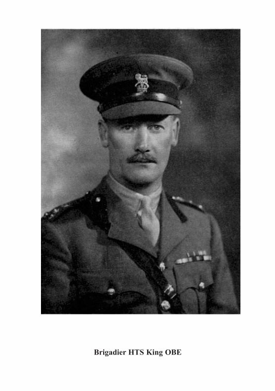
Brigadier HTS King OBE

MEMOIRS
BRIGADIER H. T. S. KING, OBE
HORACE TOWNSEND STUART KING was born on 9 October 1896, the eldestson of Robert Stuart King of Rohika, Dharbhanga, India. He was educatedat Clifton College and the Royal Military Academy, Woolwich and com-missioned into the Royal Engineers on 27 October 1915.
After completing a war-time course at Chatham and at the Signal ServicesTraining Centre he was posted to the Western Front where he joined 49Signal Company RE in August 1916. In 1918 he served with XXII CorpsSignal Company and in 1919 he returned home and spent a year at the SignalTraining Centre at Maresfield.
The following year be began his Supplementary Courses at the School ofMilitary Engineering, Chatham, and at Cambridge University, where hebecame an Undergraduate of Corpus Christi College and was awarded a Bluefor tennis. At the conclusion of his Supplementary Courses he served at theSchool of Electric Lighting, Gosport, both as a pupil and later as an instructor,and at the Experimental Bridging Establishment, Christchurch. During theyears 1922, 1923, 1925 and 1926 he played hockey for the Army side. As atennis player, besides gaining a Cambridge Blue, he won the Army SinglesChampionship in 1924 and with L. C. Owen, the Army Doubles Champion-ship also. He was a member of the Army team which won the Inter-ServiceTennis Championship that year.
In 1926 he was posted to India as a captain and joined the Military WorksService first as Garrison Engineer Rawalpindi and later at Nowshera and atPeshawar. He took part in the 1930-31 North West Frontier Campaign.
On returning from India he became DCRE Belfast and in 1933 he wasgiven command of 23rd Field Company then forming part of the 1st Divisionat Aldershot. In 1937 he was posted to Malta as DCRE Roads and Buildings.
On the outbreak of war he was recalled to the United Kingdom and wentto France in command of a field company in the ill-fated 51st HighlandDivision. He managed to extricate his company from the German trap atSt Valery and brought them safely back to England in June 1940. In Septem-ber 1940 he was appinted CRE Bomb Disposal in the London Area, and heheld that highly responsible and arduous post throughout the "Blitz" on theCapital.
In 1941 he was made CRE 45th Division and in March 1942 ChiefEngineer XI and later of II Corps. From 23 September 1943 until 2 October1945 he was Commandant the School of Military Engineering, then located atRipon except for the Trades Training Wing which remained at Chatham.
In 1946 he was posted to Egypt where he became Deputy Engineer-in-Chief Middle East Land Forces. In 1948 he was made ADC to the King.His last appointment was Chief Engineer Scottish Command. He retired on24 May 1951.
He married twice, firstly in 1926 to Kathleen Mary Darley, daughter ofJohn Percy Stott of Cullybackey, Northern Ireland, who died in 1944. Theyhad two daughters and a son. His second marriage in 1951 was to RosemaryJennifer, daughter of Major F. R. Hedges of Wallingford Castle, Berks, andwidow of Captain A. F. Wells, at that time she was a Lieut-Colonel WRAC,OBE, and a JP.
R.E.J.-II
206

TIIE ROYAL ENGINEERS JOURNAL
In company with seven other previous Commandants of the School ofMilitary Engineering, he visited Chatham on 20 July 1962 on the occasion ofthe 150th Anniversary of the SME when the Royal title was bestowed uponthe School.
Brigadier King died in the British Military Hospital in Hong Kong on18 January 1964 after a stroke. He and his wife were visiting one of hisdaughters married to a Gunner Officer serving on the staff in Hong Kong.The funeral took place on 21 January in the Garrison Church, VictoriaBarracks. A pall-bearer party of nine Royal Engineer Warrant Officers andSergeants carried the coffin into and out of the Church and the service wasattended by many officers and men and their wives of the Corps and by theStaff, headed by the Chief of Staff and the CRE Hong Kong. A cremationtook place at Little Sai Wan Crematorium where his ashes were scattered.A Memorial Service was held at St Mary's Church, Wallingford, on 5 February1964.
Brigadier King had an unusually analytical mind and applied this parti-cularly to the games in which he excelled. He was, in consequence, an out-standing instructor, and it is not at all surprising that one of his daughtersbecame a WRAC tennis champion.
He was a loyal friend and won the affection and admiration of all whoserved with him and accepted his high standards of conduct and intellectualhonesty.
m
207

BRIGADIER E. H. KELLY, DSO, MC
EDWARD HENRY KELLY who died on 27 December 1963, aged 80 years, wasthe son of Major-General F. H. Kelly, CB, CMG. He won the Sword ofHonour at the Shop and he was commissioned into the Corps in July 1902.
After completing the usual junior officer courses at Chatham he wasposted to the Bridging Battalion RE at Aldershot where he spent a year. In1904 he qualified at the School of Musketry, Hythe and the following year hecompleted an Advance Course at Chatham.
On posting to India in 1906 he joined the Depot Company of the BengalSappers and Miners at Roorkee. He served in both 1 Company and 3 Com-pany, and with the former unit he saw active service during the Chitralcampaign, and again during the Mohmand operations on the NW Frontier.In 1909 he became Adjutant of the Corps of Sappers and Miners at Roorkee.Shortly after taking up his duties, together with his Commandant Lieut-Colonel G. M. Heath, he tried to carry out a reconnaissance by night in aballoon during manoeuvres. Unhappily the balloon landed in "enemy"territory and both its occupants were "captured". Although he still had ayear to go before promotion to Captain he was given command of 1 Companyin November 1912.
On the outbreak of war in August 1914 Kelly was both in command of1 Company and the officiating commander of 4 Company. He was not, how-ever, to take either of these units overseas; he was instead transferred to theHeadquarters of the Meerut Division as Assistant Field Engineer and heproceeded in that capacity to France with the Indian Expeditionary Force.On arriving in France his Division was soon in action and on 13 November1914 he was transferred to 3 Company taking part in the battles of NeuveChapelle and Festubert in the spring of 1915. For a most daring trench raidby night in which he was wounded Kelly was awarded the MC. He was alsomentioned in despatches. In July 1915 he was given command of 2nd FieldSquadron Bengal Sappers and Miners with the Indian Cavalry Corps and inJanuary 1916, after the departure of the Indian Expeditionary Force fromFrance, he became GSO3 in Headquarters V Corps. Later he became aBrigade Major to an infantry brigade and in September 1916 he was awardedthe DSO for conspicuous gallantry in organizing the concentration of hisbrigade by night and for his personal direction of bombing attacks from aflank when the attack had been held up by uncut wire, as a result 1,000 yds oftrenches were taken and 300 prisoners captured. Shortly after this exploithe was made GSO2 VII Corps, and in May 1918 he became GSO1 5th Armywith the rank of Lieut-Colonel. Besides his award of the DSO and MC hewas between 1915 and 1919 mentioned in despatches seven times.
After the war he was sent to the Staff College, Camberley, and on graduat-ing from there he was posted to Chatham where he became Chief Instructorin Fortifications in 1922. In 1926 he was given a brevet colonelcy and postedto Headquarters London District. Two years later he was selected for theImperial Defence College and on graduating from there he was posted toArmy Headquarters India as Deputy Director of Military Intelligence. Hislast appointment was Brigadier General Staff, Headquarters British Troopsin Egypt. He retired in July 1936.
In 1918 he married Helen Beatrice, widow of Major R. Carson, RA; theyhad no children. His wife died in 1953.
MEMOIRS 208

TIIE ROYAL ENGINEERS JOURNAL
BRIGADIER D. CAMPION, CBE
DONALD CAMIPION was born on 18 November 1898, the elder son of Bernard
Campion, QC. He was educated at Marlborough College and the RoyalMilitary Academy, Woolwich, and commissioned into the Corps in January1918.
After a short war-course at Chatham he was posted to the Western Frontin October where he joined the 84th Field Company, a company in the 20thDivision then forming part of VII Corps. He saw service with the companyduring the "Advance to Victory" and with the Army of Occupation on theRhine until the end of 1919.
On returning home he was sent on a course to the School of ElectricLighting, Gosport, and in the second half of 1921 trooping season he sailed
for India where he joined the Bengal Sappers and Miners at Roorkee. Fromthere he was posted as a company officer to the 5th Field Company at Rawal-pindi. After a year in that unit he was sent to command the Chitral Platoonof the Bengal Sappers and Miners at Drosh where he spent another year tocomplete his overseas tour.
On returning home he completed his Supplementary Courses at the Schoolof Military Engineering, Chatham and at Cambridge University. In January1926 he became Adjutant of the 26th Anti-Aircraft Battalion (LondonElectrical Engineers) RE (TA), which appointment he held for four yearsbefore entering the Senior Wing of the Staff College, Camberley as a student.On graduating from Camberley he spent a year at Blackdown in the 1st Anti-Aircraft Searchlight Battalion RE before obtaining his first staff appointmentas a GSO3 in the Military Intelligence Branch of the War Office in January1933. A two-year tour of duty in that appointment was followed by anotherof two years as GSO3 at Headquarters Aldershot Command. In 1936 hereturned to the War Office as a Deputy Assistant Master General of theOrdnance, a post he held until April 1940. He had been made a brevet majorin 1936 and a brevet lieut-colonel in 1939, and with the war came rapidpromotion. In 1941 he became a Brigadier and went to Washington as DeputyDirector of the British Army Staff there and Senior Staff Officer of the
Engineer Section of the British Military Mission charged with the procure-ment of engineer equipments and stores required by British Forces in alltheatres of operations, a task for which his previous experience in the MGOBranch of the War Office well fitted him. At the end of the war he returnedto the War Office as Director of Army Requirements, an appointment heheld until his retirement in September 1946.
He was made an Officer of Merit USA in 1943 and created CBE in 1946.During the late '20s and early '30s he frequently represented the Army at
tennis. After his retirement he was a great supporter of the Royal EngineersAssociation and he was the Founder Member of the Northampton Branch.Recent ill-health, however, curtailed his REA activities.
In December 1923 he married Anne Joyce, younger daughter of JohnMartin, Esq, and Mrs Martin of Great Houghton Hall, Northampton. Theyhad one son.
He died on 17 January 1964 at Stampton Lodge, Towcester, Northants inhis sixty-sixth year.
209

MEMOIRS
BRIGADIER E. R. L. PEAKE, CBE, MC
EDWARD ROBERT LUXMORE PEAKE was born on 9 October 1894, the elderson of T. P. Peake Esq, Indian Forest Service. He was educated at Chelten-ham and the RMA Woolwich and commissioned into the Corps on 12 August1914.
After a short course at Chatham he was posted within a year of beingcommissioned to the Western Front where he served throughout the warwith RE Signal units. He was awarded the MC in 1915 and he was twicementioned in despatches. At the end of hostilities he was an acting majorcommanding B Corps Signal Company RE.
In August 1920, after completing his Chatham courses, he was sent onSurvey duty to the Gold Coast where he spent the next five years. Thisoverseas tour was followed by a staff appointment with MI4 at the WarOffice where he became in 1928 a GSO2.
In 1930, with the temporary rank of Lieut-Colonel, he became the SeniorBritish Representative on the Northern Rhodesian-Belgian Congo BoundaryCommission. The work of the commission extended over three years andat its conclusion Peake was specially employed under the Ministry of Agri-culture and Fisheries at the Ordnance Survey, Southampton.
From October 1940 to November 1941 he was Assistant Director ofSurvey, Home Forces. That appointment was followed by another tour ofduty with the Ministry of Agriculture and Fisheries in the OrdnanceSurvey. In 1943, with the rank of Brigadier, he became Deputy Director-General Ordnance Survey a post he held until his retirement in October1946. He was created CBE in the 1947 New Year's Honours List.
After retiring he was employed from 1947 to 1952 as Chief of AeronauticalCharts and Information Branch, International Civil Aviation Organization,Montreal, Canada.
He married Audrey Danvers Rutherford Hyde the daughter of SydneyHyde Turner on 28 April 1928 at St Mark's Church, North Audley Street.They had a son and a daughter.
He died at Guildford on 27 April 1964, aged 69.
210

TIIE ROYAL ENGINEERS JOURNAL
COLONEL A. D. CARDEN, DSO
ALAN DOUGLAS CARDEN died in Chippenham Hospital on 12 April 1964 in his
ninetieth year. He was the fifth son of Major-General George Garden of the5th (Northumberland) Fusiliers.
He was commissioned into the Corps on 12 December 1894. After complet-ing his junior officer courses at Chatham he spent several years in submarinemining and electric light duties, serving with 34 Submarine and MiningCompany RE at Gravesend (1897-1900), then at the School of MilitaryEngineering, Chatham as an Assistant Instructor in Electricity (1900-1905)and finally in command of the West India Submarine Mining Company REat Jamaica. In 1906 when submarine mining duties were handed over to theRoyal Navy Carden joined the 44th Fortress Company RE, also stationed atJamaica, as officer-in-charge of defence electric lights.
On returning from the West Indies in 1907 Carden became associatedwith military flying. His first appointment was Assistant Superintendent atthe Balloon Factory, South Farnborough (now the Royal Aircraft Establish-ment). He was one of the "crew" of the Xulli Secundus, the first militaryairship, when it flew in its remodelled form in 1908. He was from 1910-13also closely connected with the development of powered aircraft becoming oneof a private syndicate of three, including Colonel J. E. Capper and theMarquis of Tullibardine, which endeavoured to develop for military purposesa monoplane designed initially by Lieutenant J. W. Dunne of the WiltshireRegiment who had been invalided from the Army after the South AfricanWar. This officer had also developed gliders which showed a remarkabledegree of inherent stability in flight. Lack of funds available to the syndicateprevented their final development of the Dunne aircraft. Carden, however,gained his pilot's certificate by flying this type of machine. The Frenchmanufacturing rights of the aircraft were eventually acquired by the AstraCompany and the British rights were bought by Armstrong Whitworth and,although neither firm actually pursued the development of the Dunne aircraftat the time, some of the ideas incorporated in its original design have beenre-used in the tail-less type of aircraft with swept-back wings being developedtoday. When the Air Battalion RE was formed in 1911 Carden was given theappointment of Experimental Officer. With the formation of the Royal FlyingCorps on 13 May 1912, the Air Battalion RE was disbanded, many of itspersonnel being absorbed into the newly-formed Corps. Garden, while stillremaining a Sapper officer, stayed on at Farnborough and in August of thatyear he was made a Squadron-Leader RFC with the temporary Army rank ofMajor. He remained with the Royal Flying Corps (renamed Royal Air Forcein 1918) throughout the First World War, rising to the rank of Wing Com-mander/Lieut-Colonel, and for his services he was awarded the DSO.
In July 1919 he returned to Royal Engineer duties as E and M officer to theChief Engineer Western Command at Chester. In January 1921 he was postedto the Central Engineering Board at the War Office and he became a Memberof the RE Board. On promotion to substantive Lieut-Colonel in 1921 he wasgiven command of the 1st AA Searchlight Battalion RE, then stationed atBlackdown. He held that appointment for three years after which he returnedas a Colonel to the RE Board at the War Office. He retired in August 1930.
He married, on 2 January 1913, Nie Constance Mary, widow of Captain
211

J. D. Dauncey the Dorsetshire Regiment, only daughter of Dr Lithgow ofFarnborough and grand-daughter of Colonel the Honorable Ernest Curzon,52nd Oxfordshire Light Infantry, son of the 1st Earl Howe. His wife diedin May 1949.
A younger brother, Lieut-Colonel E. D. Garden, OBE, the famous Sapperathlete, who was one of the pioneers in the introduction of wireless into theArmy, died two years ago, aged 79 years.
CAPTAIN W. H. LIVENS, DSO, MC
CAPTAIN WILLIAM HOWARD LIVENS who died in a London hospital on 1February was well known as a gas expert in the First World War. He waseducated at Oundle and Christs College, Cambridge. He was an expert shot,being Captain of the University Rifle Team and a member of the EnglishEight Rifle Team.
He was among the first temporary commissioned officers to enter the Corpsin 1914. After serving in France as a divisional signal officer, he transferredto Brigadier C. H. Foulkes' Special Brigade RE in 1915 where his expertknowledge of both engineering and chemistry and his inventive genius,powers of improvisation and drive were invaluable in the development abinitio of gas warfare-the task allotted to the Special Brigade. His chiefinvention was the "Livens Projector" which he developed with his father,a one-time Vice-President of the Institution of Mechanical Engineers andchief engineer of Messrs Ruston and Hornsby.
The weapon consisted basically of a welded steel tube from which gascanisters could be projected, the projectors could be fired electrically inlarge numbers simultaneously. The bursting canister produced a highlylethal concentration of gas. At the Battle of St Quentin in March 1918, 3,000Livens Projectors, each projecting 30 lb of phosgene, were fired simultane-ously into the German trenches. He also developed flame-throwers usedduring the Battle of the Somme. Many of the stories about how he boldly cutthrough red tape and adroitly obtained top priority for his projects have be-come almost legendary.
LIEUT-COLONEL L. V. S. BLACKER, OBE, TD, AFRiES
LIEUT-COLONEL LATHAM VALENTINE STEWART BLACKER who died at the ageof 76 years on 29 March, was the inventor of four "Spigot" weapons thathelped to win the Second World War, namely the spigot mortar (BlackerBombard), the PIAT anti-tank gun, the AVRE Petard and the Hedgehoganti-submarine weapon. More recently he developed a jet for the Bloodhoundmissile and an "anti-bandit" weapon used by the police.
MEMOIRS 212

TIIE ROYAL ENGINEERS JOURNAL
Colonel Blacker on leaving the RMC Sandhurst was commissioned into
the QO Guides, Indian Army in 1909. He qualified as an aeroplane pilot in
1911. He served in the First World War in France with his Regiment and
with the Royal Flying Corps. He was twice wounded. After the war he
served in the Trans-Caspian Campaign and in the Afghan War of 1919 and
in other operations on the NW Frontier. In 1933 he was chief observer of
the Houston Everest Flight Expedition which made two successful pioneerflights over the mountain, in 1935 he was promoted Licut-Colonel in the
58th Sussex Field Brigade RA.Blacker's inventive genius was described by Norman Kemp in his book
The Devices of War published in 1956 and reviewed in the December 1956
issue of the RE Journal by Major-General B. T. Wilson. In a letter to the
Editor, published in the March 1957 issue of the Journal, Colonel Blackerwrote:-
"Your reviewer, in his recent notice of Devices of War, was good enough
to make some kind remarks about myself. He quite correctly referred to meas a Guide.
All the same, I feel it a duty to the Corps of Royal Engineers to tell yourreaders that the four 'Spigot' weapons of the 1939/45 War, the 'Bombard',the anti-submarine 'Hedgehog', the 'PIAT' and the 'Mortar, recoiling Spigot',
alias the 'Petard', were the culminating fructifications of a germ implantedin 1904/05 by four attested Sappers of the East Anglian Royal Engineers.
Their leading spirit was, afterwards, Lieut-Colonel G. L. Ritchie, Royal
Scots Fusiliers; another was, rather later, the Right Reverend the Bishop of
Blackburn and another myself.The mortar then developed was inspired by the wooden, or bamboo
weapons used by the Japanese in Manchuria. Closely resembling it were
those mortars for jam-tin projectiles extemporized in Flanders, notably by
the Royal Bombay Sappers and Miners. The 'hollow-charge' of the PIAT
owed something to the instruction imparted to us of the Cavalry and Infantry,in Peshawar in 1909 by the Subaltern of No 3 Field Coy, Bengal Sappers and
Miners, P. C. S. Hobart, who told his hearers about the 'Monroe' effect andplastic HE.
The wheel came full circle in 1944, when that subaltern became the Com-mander of the 79th Armoured Division, whose Royal Engineer AssaultRegiments in Normandy used, and expressed their gratification with, the
'Petard', and its 'Flying Dustbin', the fourth of this series of low velocitybut very high-powered weapons. The 'Petard' of the AVRE was, indeed,
almost a much enlarged PIAT. The Army owed, as so often, a debt to the
support of the unconventional, by the Royal Engineers."
213

Book Reviews
NEITHER FEAR NOR HOPEBy GENERAL F. VON SENGER UND ETrERLIN
(Defender of Cassino)(Published by Macdonald & Co Ltd (Publishers). Price 40s)
The author of the book under review is General von Senger und Etterlin, who isbest known to British soldiers as the German Commander at Cassino in the ItalianCampaign 1943-44. He was born into a Roman Catholic family in South WestGermany; and, after a liberal education that included a Rhodes Scholarship atOxford, he was commissioned into the German Army as an infantryman in 1914.Between the wars he served in a horsed cavalry regiment and in 1939 was givencommand of the only existing cavalry brigade in the Wehrmacht. He had never beento the Staff College, which was the normal stepping stone to high command in theGerman Army; but he was made of the stuff that shines in battle and promotioncame to him steadily. He fought in the French campaign; then in Russia in 1942-43;in the Mediterranean theatre after that; and at the end of hostilities in Europe wascommanding a Corps in Italy.
The theme throughout the book is the dilemma of a man with a cultivated mindand a wide international outlook serving a regime of which he did not approve, butcaught in a war which patriotism compelled him to wage. He tells us how, whenFrance fell, his wife wept. The victory over France gave Hitler's ambitions an impetusthat could only end in ruin. If Hitler won the war, European civilization wouldvanish from the face of the earth: if Hitler lost, Germany was doomed. It was aproposition which could not inspire hope; nor in a stout heart must it give rise tofear. Hence, presumably, the title NeitherFear nor Hope. (The German title is different.)
This dilemma in the mind of the author is the dominant but not the only interest:the reader is certain to be interested in the man himself. He was not of the professionalmilitary caste; and even in the British Army he would be regarded as a man of wideinterests outside his profession-architecture, beauty, scenery, history and music allattracted him. But none of these things diverted him from a proper understanding ofthe profession of arms. He writes with understanding on many military problemsboth great and small.
There are fascinating pen portraits of many German personalities, includingHitler. We get telling glimpses of Kesselring and other well-known military figures,as well as lesser men such as the author's batman, or his friend General Baade, whomust have been an original character. (Baade habitually wore a captured kilt overhis riding breeches, and was thought at one time-incorrectly as it happens-to haveaccepted an invitation on Christmas Eve to dine with the enemy.) Thus humaninterest is imparted throughout.
The military reader will also be interested in the strategical and tactical musingsof the author. He shows how circumstances have altered the role of the commander;how better communications have reduced his freedom of action; and how, in theGerman Army, a "faith in the Fuhrer" was sometimes regarded as a better passportto high command than professional skill. He reflects upon leadership at lower levels;and pays tribute to the courage that was shown by so many on both sides in the bitterstruggles for Cassino.
He gives his views on armoured warfare, organization, staff work and on "Infantry,the Queen of the Battlefield". It is not possible in a review to present the author'sconclusions; the reader must seek them for himself. He will never be bored, thoughhe may not be in complete agreement.
214

TIIE ROYAL ENGINEERS JOURNAL
There is one phrase that requires more explanation than it gets: the author fre-
quently refers to a "Council of War", particularly in the section on the "Cassino
Battles in Retrospect". This phrase is anathema to the British soldier and one would
like to cross-question the author on some aspects of the subject. For instance (on p. 221)
comes the following passage: "Neither the corps commander nor even the army com-
mander play any more significant part in such a council than the local expert who
puts his proposals to the vote and must act according to the council's decision".
Your reviewer never beheld anything like this in our army either in defeat or victory;
and one would like to hear more.The tale the author tells is linked throughout by the thread of his own doing.
Naturally there is much military detail such as the moves of corps, divisions and
regiments, and accounts of actions great and small that came within the author's
view. These are for soldiers only; but many passages will interest the civilian reader
too.The end of the books tells of the author's experience in defeat and as a prisoner of
war in South Wales. He does not recriminate; and one hopes that we were not too
corrupted by victory to be devoid of all chivalry.The translator, George Malcolm, is to be congratulated. Liddell Hart contributes
a typically lively foreword. The maps are adequate and the photographs good.
Altogether, a good book though rather a costly one; easy to read and interesting
throughout.M.C.A.H.
THE MARCH ON DELHI
By A. J. BARKER
(Published by Faber & Faber. Price 42s)
As if to make up for the "Forgotten" years, the five months, February to July
1944, which saw the siege and relief of Imphal, the epic of Kohima, and the turn of
the tide of Japanese success on the mainland of Asia, have in recent times received
their fair share of publicity. In The March on Delhi, Colonel Barker takes us once
again over the now familiar terrain, but this time with a welcome difference. Gone
are the chummy, "I was there", blood-and-mud clich6s of which we have long since
tired; and in their place this author presents a workmanlike picture of the operations
viewed as a whole, and not only from our side of those hills, but from that of the
Japanese also. His approach includes a foreword from the pen of Lieut-General
Mutaguchi, at that time Commander of the 15th Japanese Imperial Army, which
attempted the invasion of India, and so nearly succeeded; as well as a short course of
instruction in the "Bushido" code of military honour which motivated our enemy and
sustained his efforts beyond rational limits.Beginning with a review of the situation in the Far East generally at the start of
that year, Colonel Barker traces the development of the Japanese plan for the capture
of Imphal, which so alarmingly disrupted our own preparations for the re-conquest
of Burma; and describes the counter-measures hastily improvized to meet the threat
to India and to the vital allied link with China. That The March on Delhi was not then
intended to advance beyond Imphal, and that the all-highest Japanese Command
refused permission to follow-through their initial gains at Kohima and to drive on to
a "pretty defenceless" Dinapur, is perhaps the most exciting of the revelations from
the other side of the hill. As in Malaya two years earlier, the Japanese seem to have
been surprised at their own achievement, but fortunately less ready here to adapt
their plan to changed circumstances, and to exploit unexpected success to the limit.
The ensuing actions and reactions in and around Imphal, Ukhrul and Kohima,
as well as those farther afield in the Arakan, Lushai Hills, Northern Burma and on the
Ledo Road, fall into place in a consecutive and related narrative which other pens
have often made less clear and sometimes wholly confusing. The author is to be
215

congratulated on the composition of this tapestry and on the balance of backgroundand detail with which he fills it-a task complicated by the wide dispersion of effort
in this war of detachments, made doubly successful by the skilful interweaving of the
authentic Japanese thread. What a pity that he supports it by somewhat inadequately
planned mapping, and by such a meagre selection of not too well reproduced photo-graphs.
Of the players in this vast scene and of their exploits, from the top-brass on each
side to the humblest Jawan, Colonel Barker reports convincingly. The reader can
have nothing but respect for the individual courage, skill and discipline of our
enemy; nothing but renewed admiration for the resilience, determination and en-
durance of British, Indian and Gurkha alike in conditions probably unequalled in any
other theatre of the Second World War. Alone of the participants the much vauntedINA do not come well out of this analysis and there is little sympathy to be found for
them-rather for the Japanese Commanders, to whom their presence must at timeshave proved more of a hindrance than a help.
The part played by the Air, and obviously by air transport in particular, receives
its due; but one is led again to wonder at the optimism of an enemy committed, at
that period in the history of warfare, to such a formidable task with wholly inadequate
air support. Had the Japanese air force been present in effective strength, the storymight indeed have been different.
For the Sapper there is little here of technical interest and Engineers are hardly
mentioned, though their contributions on both sides was clearly both continuous and
gruelling. It is probable that nowhere in the history of the Corps, of the IndianEngineers and of the three Corps of Sappers and Miners, have their units been more
consistently and unremittingly engaged in what is so frequently mis-termed "the
infantry role". In the engineer context the reader may from time to time be misled
by the author's loose employment of the word "road" to describe what were at best
fair-weather bridle-tracks, at worst shelves of sliding mud in the flanks of the hills.There is a comprehensive index, a well set-out Order of Battle, and an Appendix
of biographies of the principal characters in the play. The March on Delhi offers a most
readable and professionally reliable account of a struggle which was, in fact, rather
more than the "glorified boy-scouting" as which it was seen by at least one senior
commander distinguished in the European Theatre.L.E.C.M.P.
ELEMENTARY PHOTOGRAMMETRY
By D. R. CRONE, CIE, OBE, MSC
(Published by Edward Arnold (Publishers) Ltd, 41 Maddox St, London Wi.Price 28s)
This book is intended for use by students studying for a degree in Civil Engineer-
ing as a background text to the practical part of the photogrammetry course. In
particular the book relates to the course given to third-year students of Civil Engin-
eering at the Queen's University of Belfast.In his introduction the author tells us that the scope of a civil engineer's knowledge
of photogrammetry should include at least three aspects. Firstly, he must know what
to specify as his requirement for photogrammetric survey. Secondly, he must be able
to assess the merits of offers by firms tendering for a particular task, and this involves
a knowledge of different techniques as well as accuracies and tolerances. And thirdly,
he must be able to derive other information from the photographs besides that which
the contractor will extract for him.To cover adequately this ground alone would require far more space than the
author has allowed himself and he has, therefore, confined himself to basic principles
aimed at a general understanding of the subject in accordance with his own definition
216BOOK REVIEWS

THE ROYAL ENGINEERS JOURNAL
of a civil engineer's requirements. The general approach is to devote the first fewchapters to theoretical considerations, in particular the fundamental geometricalpropositions forming the basis of the subject. The rest of the text deals with practice,including drawing office equipment and methods and concluding with a short his-torical summary. The absence of complicated mathematics will no doubt be to theliking of many readers although the statement that the text has been written assuminga knowledge of mathematics not beyond the General Certificate of Education atOrdinary Level is somewhat apocryphal.
The average student should not find this book difficult to follow. It is presentedin a clear, logical manner and is illustrated with well-drawn diagrams. The notationis based on British Standard 1991 Pt I 1954, and is clear and consistent throughout,which is indeed a blessing when trying to follow diagrams and formulae. The printingis excellent and the bibliography, though limited to related works in English is ade-quate, up to date and clearly referenced.
A striking characteristic of the three chapters dealing with perspective theory,theory applied to surveying and drawing office methods is the author's propensityfor careful analysis. He examines the changes in the inner and outer perspective dueto the change in attitude of the aircraft at each exposure station and then analyses theeffects of these changes on scale relationships, angular relationships at the variousperspective centres and heights of points in the focal plane. He derives expressionsfor these relationships which can be readily evaluated using any combination ofassumed values. This is all sound, basic material and essential to a proper under-standing of photogrammetry at a more advanced level.
The main criticism of the book concerns the inclusion of certain theoretical aspectsand practical methods which are not likely to be encountered in practice nowadaysand might, therefore, have been omitted. Examples of this are those paragraphs inchapter 2 (perspective theory) on the graphical construction of a perspective gridand the construction for common convergence.
Again, in chapter 8 which deals with drawing office methods, it is most doubtfulwhether the descriptions given of the spatial resection of a single photograph, mappingfrom single photographs and from high oblique photographs are worth includingnowadays.
On the other hand certain items have been omitted which many will consider arethe concern of the civil engineer, for example, there is nothing on photographicinterpretation or photo mosaics. Chapter 5, on the subject of the photographic task,seems incomplete without the addition of a typical set of calculations such as need tobe prepared when planning a photographic task, including the choice of lens andB/H ratio.
Finally, a special word on chapter 9 which deals with stereo plotting machinery.Students may well find the somewhat abbreviated descriptions of precise stereoplotters insufficient for a clear understanding of the principles of operation. Thediagrams cannot be faulted but after reading the descriptions of the C8, A7, A8 andthe Thompson-Watts plotter one is left with only the most vague conceptions. Sincephotogrammetric plotting machinery is of the greatest value to engineers either whencontours are required or for making precise measurements it seems a pity thatmore space could not have been devoted to a fuller description of them and to thefactors governing the choice of instruments for particular projects.
Summarizing, this book will be a worthy acquisition for the libraries of thoseuniversities and teaching institutions which are concerned with teaching the funda-mental principles of photogrammetry, and although intended primarily for civilengineers it will be valuable alike to air surveyors and cartographers whose concernis the making of topographic maps and plans from air photographs.
P.C.S.
j
217

BOOK REVIEWS
NONCONSERVATIVE PROBLEMS OF THE THEORY OFELASTIC STABILITY
By V. V. BOLOTINCORRECTED AND AUTHORIZED EDITION
Translated from the Russian by T. K. Lusher and English Translation edited byG. Herrmann of Northwestern University, Evanston, Illinois
(Published by Pergamon Press, Headington Hill Hall, Oxford. Price 6os)
Due to technological advances made in the past ten years a number of previouslyunknown phenomena have made themselves apparent with the growth of knowledgein respect of elastic instability under aerodynamic forces, "follower" forces, and theassociated forces of inertia and friction.
Most of these phenomena have been discovered in an international field of researchand the dissemination of information concerning them has, hitherto, been just as widein the manner of its publication.
This book is an attempt by Professor Bolotin of Moscow to present in a unifiedform the nonconservative problems of the theory of elastic stability which havedeveloped since the original subject works of Euler, which in themselves are limitedin their range of application.
Aerodynamic and hydrodynamic loads, the forces acting on parts of turbines andelectric machines, and the loads induced in parts and linkages of automatic controlsystems are in most cases nonconservative forces, and the problems they pose liemainly in the development of present-day mechanical, aeronautical and rocketengineering.
The book contains an introduction and four chapters. The first chapter coversgeneral problems, their formulation and methods of solution. The remaining chaptersare given over to applications and the study in detail: the stability of elastic systemswhich, during the process of loss ofstability under the action of nonconservative forces,behave according to some predetermined law (so-called "follower" forces); thestability of high-speed rotating elastic rotors under hydrodynamic and electric forcesand internal friction etc; stability of elastic systems in high-speed gas flow; supersonicflutter of elastic plates and shells. Some of the problems are considered in non-linealform after the loss of stability.
A short chapter at the end of the book outlines a number of suggested directionsfor future research.
This well-produced book, comprising some 300 pages, is highly suitable for refer-ence by graduate students, scientific workers, and design engineers dealing withstructural stability, aeroelasticity, high-speed rotating machinery, vibration analysis,and the theory of oscillators.
F.T.S.
FATIGUE RESISTANCEBy P. YE KRAVCHENKO
Translated from the Russian by 0. M. Blunn
Translation edited by N. L. Day, BSc (Eng), PhD, AMIMechE
(Published by Pergamon Press Ltd, Headington Hill Hall, Oxford. Price 30s)
This textbook was first published in the USSR in I96o and a revised edition wasissued in 1962. American and British scientists recommended the Pergamon Instituteto publish the book in the English language because of its practical value to engineersand technicians employed in engineering design and development.
In spite of the fact that fatigue failure has been studied since 1919, and the litera-ture printed on the subject is extensive, only scant references to the subject are made inEnglish text books on Strength of Materials. Graduate students will, therefore, find
218

TIIE ROYAL ENGINEERS JOURNAL
this book extremely useful, particularly the preface that outlines the growth ofexperience, experiment and knowledge of the subject in Western countries.
Commencing with the definitions "that metal fatigue is defined as the gradualfailure of a metal under the action of cyclical stresses; and that metals which are ableto withstand a large number of cyclical stresses without failure are said to have ahigh fatigue or cyclical strength", chapter I details the main types of cycles andtheir criteria, test equipment, the method of testing, the production of fatigue curvesand maximum safe stress diagrams.
Chapter 2 deals with the theory of metal fractures and their external appearance;whilst chapter 3 studies the factors that effect the endurance limit under symmetriccyclical stresses. The ways of improving the fatigue strength of engineering com-ponents are discussed in chapter 4, and these cover the principles of production designand technology. Chapter 5 is devoted to the fundamentals of endurance limit analysisfor the determination of the reserves of strength under symmetric and non-symmetricstress cycles or a combination of bending and torsion.
Two appendices present tables of the mechanical properties of grey iron andcertain steels, and the values of various coefficients used in fatigue calculations.
As the book was originally intended for students taking the USSR training course"Strength of Materials" references are included which refer to Soviet Standards andtesting machines.
This I o-page book is well produced and the type is easy to read. Most of the textis descriptive in nature.
F.T.S.
TELEMECHANICSBy V. S. MALOV
Translation from the Russian by F. ImmirziTranslation Editors: B. Meltzer and G. E. Walker
(Published by Pergamon Press Ltd, Headington Hill Hall, Oxford. Price 35s)Telemechanics may be defined as the branch of engineering science that deals
with the theory and practice of transforming and transmitting over a distance theinformation required remotely to operate and control the apparatus and equipmentemployed in production processes, utility services, transport, flight and other special-ized applications.
This book, Volume I of the Pergamon International Series of Monographs onAutomation and Automatic Control, presents the basic concepts and definitions oftelemechanical systems, and the theory of telemechanical signals, telemetering systems,and remote-control and remote-signalling systems. It does not contain descriptivereferences to any specific telemechanical apparatus, Russian or otherwise.
The text on telemechanical systems is largely devoted to an explanation of thecomparatively new theoretical branch of science information theory, its probability andmathematical statistics. The section dealing with telemechanical signals covers thenature of signals used in the transmission of messages and differentiates betweencontinuous and discrete signals, modulation forms, codes with enhanced noise-immunity and the methods used in the separation of signal elements. Telemetering,that is the long-distance transmission of monitored meter readings, is discussed insome detail for systems using continuous or discrete signals, or multi-channels. Theoperational principles of remote control and remote-signalling systems are given,together with descriptions of the more important units used in the functional stages.
The text is mainly descriptive and well illustrated with generic block diagramsand circuits. Although condensed into Ioo pages it is sufficient to enable the non-specialist engineer to obtain a fair knowledge of this particular branch of engineering.
A number of appendices provide: A table of Binary Numbers; a table of LogarithmsBase 2 for numbers i-50; and Frequency Spectra of Certain Signals. F.T.S.
219

BOOK REVIEWS
SOME PROBLEMS IN THE THEORY AND ASSESSMENT OF TURBO-JET
ENGINES
By K. V. KHOLSHCHEVNIKOV
Translated from the Russian by Wm E. Jones, UK, Atomic Energy Authority
Translated edition by Dr B. P. Mullins, Deputy Chief, Scientific Officer, Ministry
of Aviation, Farnborough
(Published by Pergamon Press, Headington Hill Hall, Oxford. Price 35s)
This text-book is Volume 4 of Division III in the Pergamon International Series
of Monographs in Aeronautics and Astronautics which deals with propulsion systems
including fuels.The text, which develops from first principles the basic general theory of the
design and performance of turbo-jet engines, is presented mathematically and con-
sists entirely of algebra that is suitable for first and second year technical college
students of aeronautical engineering.
The book has two chapters. The first expounds the general problems of the
theory of turbo-jet engines in relation to initial equations and conditions of thrust,
specific thrust, and specific fuel consumption; also the optimum thermodynamic
parameters for determining minimum fuel consumption, optima of gas temperature
and expansion ratio, and special features evolved by the use of reheat chambers.
The second chapter covers the selection of engine parameters for rated flight condi-
tions taking into account aerodynamic and design data for the compressor and turbine.
The text is illustrated by a number of graphs and the book is excellently produced.
This volume will be of particular interest to performance engineers employed in
the turbine industry and students of aeronautics and astronautics. It is also suitable
for reference use in technical libraries.F.T.S.
PROBLEMS OF THE DESIGN AND ACCURACY
OF COMPLEX CONTINUOUS ACTION DEVICES
AND COMPUTER MECHANISMS
Edited by N. G. BRUYEVICH
Translated from the Russian by Gerald Segal
English Translation Editor: A. M. Andrews, PhD
(Published by Pergamon Press Ltd, Headington Hill Hall, Oxford. Price 70s)
This is Volume 8 of the International Tracts in Computer Science and Technology
and their Application, as published by Pergamon Press. It contains a collection of
monographs dealing with aspects of the design of mechanical and electro-mechanical
analogue computing devices. All the papers are by leading Russian scientists and are
written on the basis of research carried out by the authors in 1955-56.
The term "devices" used in the title refers to the mechanisms and electrical net-
works within a computing instrument or machine. Such devices may be either
primary or complex. The primary devices are those which carry out the elementary
mathematical operations of addition, subtraction, multiplication, and division, raising
to a power, integration, differentiation etc. The choice of primary devices determines
the complex devices that can be obtained by combination to solve any prescribed
mathematical or logical function.Each of the papers is quite separate, but the book is divided into two parts.
Part I, comprising three papers, deals with:-
The problem of the Inputs and Outputs of Complex-action (ie "analogue") com-
puter devices. (The inputs of a device are those elements of the mechanism or
circuit to which the energy from an external source is fed. The outputs are the
elements of the mechanism, or the electrical circuit, from which the energy is
220

THE ROYAL ENGINEERS JOURNAL
transmitted to other devices or circuits.) The design of computers for the calcula-tion of Implicit Functions by the Method of Approximations.Random processes in the problem of the accuracy of mechanisms.Part II consists of seven papers each dealing with an investigation of the accuracyof the following Standard computer mechanisms:-The effect of Servo Systems upon the accuracy of performance of an Automated-Differentiating Friction Mechanism; a non-Automated Friction Mechanism; theCardan Transmission; a Conoid Mechanism; Mechanisms with a VariableTransfer Ratio, and Transmission by Cylindrical Toothed Wheels and its im-provement by means of adjustment.
These papers are perhaps of little use to graduate engineers wishing to learn thebasic operating theory and mechanisms of computers and their practical application;but designers and manufacturers of instruments and other intricate mechanisms willfind a wealth of information in the experimental data given in the individual papersand their associated graphs, tables and diagrams.
F.T.S.
BEAMS AND FRAMED STRUCTURESByJAcQUEs HEYMAN, MA, PhD, AMICE
(Published by Pergammon Press. Price 17s 6d)This is a textbook on the analysis of relatively simple indeterminate structures. In
addition to all the common elastic methods of analysis, there is a section on plasticmethods; the solution of the moments in beams, portals and simple multi-storeyframeworks is considered with each method.
Much space is devoted to the development of equations and relationships and thebook appears to be written for the student rather than for the practical engineer.There are several worked examples, most of which are treated algebraically and yieldformidable solutions.
The print is well spaced and easy to read; the page size, however, is only octavo,with wide margins, so that it is too often necessary to turn back a page to refer toprevious equations in any section. J.C.P.
CONCRETE FINISHES AND DECORATIONBy H. L. CIIILDE
(Published by Concrete Publications Ltd, 1963. Price 18s)This is a completely revised edition of an earlier book in the well-known Concrete
Publications series. Whilst the subject is not one to have much application for themilitary engineer under field conditions, it does give sound information for use whenmore importance can be given to the appearance and standard of finish of a concretesurface.
The first chapter in particular is of general value and gives much good advice onways of ensuring a good clean surface, free of blemishes, when a plain finish is re-quired. This could well be studied by everyone responsible for the design and con-struction of formwork, whether in timber or other materials.
Other chapters cover, with numerous examples, such aspects as exposed aggregatefinishes; the use of precast slabs as shutters; reconstructed stone; terazzo; ways forlaying special facing layers to walls; precast slab and block walls, etc. The use ofshaped plastic and rubber forms, which are becoming so popular for giving relief toconcrete surfaces, is also described.
The book is well illustrated with numerous photographs showing examples ofdifferent finishes. It should be of value to architects and engineers, especially thoseresponsible for work in both precast and in situ concrete work. J.C.P.
221

BOOK REVIEWS
RECENT TRENDS IN THE DEVELOPMENT OF THE THEORY OFPLASTICITY
By PROFESSOR W. OLSZAK, DR Z. MROZ AND DR P. PERZYNA
(Published by Pergamon Press Ltd, Headington Hill Hall, Oxford. Price 5os)
This book, originally published in Poland during 1963, is an incomplete survey of
the contemporary trends in the development of the theory of plasticity based on a
number of lectures given by authoritative scientists on various aspects of the subject
in Budapest, Grenoble, Hanover, Moscow and Vienna. The survey contains those
matters which, in the author's opinion, are typical and decisive for the future de-
velopment of the theory.The subject matter is presented in three main parts: In the first a review is made
of the research work done on the laws relating to the kinematical elements of the
strain-rate tensor, and strain accelerations of higher orders, to the dynamic elements
of stress rate and stress accelerations. Treated separately are the small and finite
strain problems, and the uniqueness problem and the extremum theorems are also
reviewed. Numerous experimental investigations are discussed to try and establish
the basic physical foundations of the theoretical structure of the modern plasticity
theory to secure as close an approach to reality as possiblePart two is concerned with the applications of the theorems to the problems of
limit analysis and limit design; the adaptability of structures and the shake-downproblem; three dimensional and axially-symmetrical problems, the boundary layer,
effects ofnon-homogenity, and the theory of granular media. The third part describes
some recent work on dynamical problems of the theory of plasticity, and concludes
with some critical remarks and discussions on future developments.An outstanding feature of this book is the large bibliography given at each chapter
end which cover an international range of further reading.The subject matter is very advanced and only suitable for reference by qualified
engineers specially employed on structural design work.F.T.S.
EFFECT OF MANUFACTURING TECHNOLOGY AND BASIC THREAD
PARAMETERS ON THE STRENGTH OF THREADED CONNEXIONS
By A. I. YAKUSHEV
Translated from the Russian by S. H. TaylorTranslation edited by the Staff of the National Engineering Laboratory
(Published by Pergamon Press Ltd, Headington Hill Hall, Oxford, in association withthe Department of Scientific and Industrial Research. Price 50s)
This book, a translation of the original volume published in Moscow during 1956,sets out the results of the author's investigations to determine the effect of the para-
meters and manufacturing technology of a metric fastening thread on the strength of
threaded connexions.In his foreword the author states that the investigations made by "foreign"
engineers on the design and manufacture of threaded connexions have been incom-
plete and the findings erroneous; and claims that his experiments prove that it is not
the production of a high-class "fit" (normally regarded as essential in highly-stressedmachine parts) which ensures satisfactory fatigue strength of threaded connexions,
but the guaranteed clearances. A number of design and manufacturing recom-
mendations are given in support of his findings. He also states that a quantitative
relationship exists between surface quality and the technological conditions of manu-
facture and the effects of this quality on the fatigue strength is stated.
The text, some 250 pages long, covers with typical Russian thoroughness most of
the aspects of the design and manufacture of threaded connexions and, as a large
percentage of the parts of modem machines are threaded, it is worthy of study by
designers and production engineers. F.T.S.
222

TIIE ROYAL ENGINEERS JOURNAL
ELEMENTARY THEORY OF ELASTIC PLATESBy L. G. JAEGER
(Published by the Pergammon Press Ltd. Price I7s 6d)This is Volume 2 of the Structures and Solid Body Mechanics Division of the
Commonwealth and International Library of Science, Technology, Engineering andLiberal Studies, and is published as a paper back booklet.
The simplest method of design for a plate or thin slab is to consider it as a series ofbeams of unit width placed side by side. This is inaccurate and does not approximateto the actual behaviour of a plate, which is far stronger than such an analysis shows itto be. If the slab is curved or cranked it is even stronger, and spans of 80 ft are builtwith hyperbolic parabaloid reinforced concrete slabs only three or four inches thick.If a more rigorous analysis is attempted, the elastic theory designer finds that he mustmaster complicated, tedious, mathematical relationships. These give the elastic orlower bound solutions, which are so complex, that the engineer prefers to use theupper bound solutions based on yield line theory. However, the two methods areinter-related and the design engineer should understand both.
The book gives a good introduction to the elastic methods, and the author hasselected subject matter which is most likely to interest the engineer. To follow theworking the reader must be familiar with elementary calculus and differential equa-tions though a valuable appendix of relevant mathematics is included. The first threechapters evolve the basic theory and apply it to rectangular plates with various boun-dary conditions. The circular plate is dealt with in a similar manner. A chapter onpotential energy methods and another on the membrane analogy make up the re-mainder of the book. There is a summary at the end of each chapter which is anexcellent innovation. There is a set of examples for the reader to solve. Despite theclear lay-out and well worked examples few engineers would read this book to get aninsight into the subject because the treatment is too mathematical. If one has to studythe subject then one might read it, but 'Theory of Plates and Slabs' by Timoshenkodeals with the subject better and in greater detail.
R.D.P.B.
DIMENSIONING FOR INTERCHANGEABILITY
By L. P. WAKEFIELD, MIED(Published by Pergamon Press Ltd, Headington Hill Hall, Oxford. Price los)Only a few production engineering firms, other than small concerns producing
simple apparatus, manufacture their machines or other products in their entirety.Most place sub-contract orders on other firms for the supply of sub-units of a specialistnature, and electrical components, high pressure fuel pumps, bearings and oil seals aretypical examples of these. In addition, occasions often arise when the volume of ordersreceived exceed the production capacity of a firm, and then sub-contracts are placedfor the manufacture of non-specialist parts, and even the assembly of sub-units.
In the latter cases, in particular, it is essential that the workshop drawings issued tosub-contractors should leave no doubt in anyone's mind as to what is required and thedimensional tolerances that are permissible. Failure to ensure this only results inassembly headaches and a great deal of financial controversy.
These matters have always been apparent to production engineers, although itwas not until 1948 that a real attempt was made, by an Inter-Services Committee, toiron out the deficiencies of drawing office dimensioning practice. The Committee'sReport, called The Dimensional Analysis of Engineering Designs, was followed byBritish Standard No 308 for setting out prescribed methods for tolerancing dimensionsfor size, position and form.
Mr Wakefield's book is based on these sources, his own practical experience indrawing offices, and the publications of the General Electric Company and the
- m 1 a
223

Ministry of Supply. In a concise but clear manner it gives in fair detail the: Methodsof Expression; Production Design Analysis; Datum Selection; Tolerances-LimitSystems; Drawing Office Standards; and a Summary of Drawing Approval Analysis.
This well illustrated, paper-backed book will be of considerable value to apprenticedraughtsmen, students of electrical and mechanical engineering, and junior produc-tion executives.
It is good value for its modest price of ten shillings. F.T.S.
DESIGN AND PERFORMANCE OF CENTRIFUGAL AND AXIAL FLOWPUMPS AND COMPRESSORS
By A. KOVATS(Foster Wheeler Corporation, New York)
(Published by Pergamon Press Ltd, Headington Hill Hall, Oxford. Price 5 guineas)This book presents a unified and up-to-date recapitulation of the fundamentals of
fluid mechanics, thermo-dynamics and the theories of design and performance for thesubject machines. It does not deal with the associated equipment of pipes, valves,controls, measuring instruments, or the design of systems for normal or specializedapplications.
As the book has been prepared for publication throughout the Western Hemispherethe author has taken the precaution of reconciling the symbols and units used inEurope to those adopted in America, and in certain cases the derivations of alterna-tive formulae are given.
Except for Chapters I and 4, which deal respectively with Fundamentals, andPumps for Special Duties, the text is more suited to the designer than the student,unless the latter intends to specialize in this particular branch of engineering practice.
The book with its easy to read print is excellently produced, well bound, and its450 pages are illustrated by a large number of design drawings and diagrams. Asummary of further reading is given at each chapter end.
In spite of the wealth of literature already published on the subject matter, thisbook would be, in my opinion, a worthwhile acquisition to the reference libraries ofdesign offices and colleges of technology.
F.T.S.
APPLICATION OF COMPUTERS IN VALVE GEAR DESIGNPREPARED UNDER THE AUSPICES OF TIIE DIESEL ENGINE SUB-COMMITTEE OF THE SAE
POWER-PLANT ACTIVITY COMMITTEE
(Published by Society of Automobile Engineers, Inc, 485 Lexington Ave, New York 17.Distributed in the UK by Pergamon Press Ltd, Oxford. Price 40s)
This publication, Volume 5 of the SAE Technical Progress Series, contains acollection of papers relating to the design problems of the valve gear systems of inter-nal combustion engines and the application of computer techniques to their solution.
Each paper was recently read to the Diesel Engine Sub-Committee USA; whosemembership consists of representatives of the Armed Forces, research institutes,universities and leading automobile manufacturers of the USA.
The papers, which are supplemented by discussion observations, are titled:-Aid of Digital Computer in the Analysis of Rigid Spring-Loaded Valve Mechan-
isms.
By M. S. Hundal, University of Wisconsin.Studying Valve Dynamics with Electronic Computers.By G. I. Johnson, Detroit Engine Div, General Motors Corp.Recent Developments in Cam Design.ByJ. H. Nourse, Engineering Consultant; R. C. Dennis, Atomic Power Develop-
ment Associates; W. M. Wood, Associated Spring Corps.
BOOK REVIEWS 224

TIIE ROYAL ENGINEERS JOURNAL
Problems in Valve Gear Design and Instrumentation.By C. A. Beard andJ. G. G. Hempson, Ricardo & Co Engrs (1927) Ltd.
These reference works provide a foundation on which specific programmes for the
research, design and development of valve gear systems could be built to suit indivi-
dual requirements. They are too advanced to be of use to mechanical engineering
students, although the papers would serve to illustrate the degree of development now
reached in the field of automobile engineering.Those engineers who are concerned with the application of electronic, digital and
analog computers in general engineering design will applaud this extension to the
ever-growing range of computer use.F.T.S.
Technical NotesCIVIL ENGINEERING
Notes from the Civil Engineering and Public Works Review, December 1963
THE CONSTRUCTION OF THE DARTFORD-PURFLEET TUNNEL: This article describes the
construction of and main features of the tunnel. Driving was carried out in com-
pressed air using conventional shields. A variety of grouts including clay, cement
and sodium silicate were used to cement the surrounding soil and cement grout
curtains were used to form "bulkheads" round the tunnel to reduce the flow of water
without using a high air pressure.
TIHE DESIGN AND CONSTRUCTION OF HARBOUR WORKS AT FIJI: Describes the con-
struction of a new deep water quay, two new slipways and a repair quay at Fiji.
The designs had to take into consideration hurricane winds up to 150 mph and
earthquakes. The main quay consists of 23-in external diameter 14-in internal dia-
meter prestressed concrete piles with a deck of precast concrete units.
DIMENSIONLESS SPECIFIC ENERGY AND FORCE EQUATIONS FOR TRAPEZOIDAL CIIANNEL
FLOW: The solution of the hydraulic equations for flow in channels is often dependent
on successive approximations or trial and error. An article in the November issue
dealt in general terms with the solution of hydraulic equations by the use of non-
dimensionless parameters. This article deals with the specific case of trapezoidal
channels and shows that the solution of such problems as the formation of hydraulic
jump can be solved by the use of tables.
THE LANGTON-CANADA IMPROVEMENT SCIIEME: Describes the construction of a new
locked entrance to Liverpool Docks. The new lock is 825 ft long and 130 ft wide with
three sliding caisson gates. The intermediate gate is not central so that there is the
choice of three different locking lengths. All the caissons for the main lock have
footways fitted to the top which fold down when the caisson is withdrawn in to its
chamber. The caisson between the Brocklebank Dock and Canada Dock carries a
roadway and railtrack which also fall as the caisson is withdrawn into its chamber.
TIlE HALLGATES SERVICE RESERVOIR: The Hallgates Service Reservoir will hold o1
million gallons of water and is part of the supply to Leicester. The walls are 20 ft
high and were designed as mass concrete gravity sections using fly ash concrete to
reduce temperature effects. The superstructure of the reservoir consists of pre-cast
beams and slabs supported on pre-cast columns.
APPLICATIONS OF DIMENSIONAL ANALYSIS METHODS TO CIVIL ENGINEERING PROBLEMS
(PART 4): This is the final part in a series of articles and deals with Foundation
Problems. Although there are indications that the dimensional analysis approach
could be very useful, the example given in this article is based on material in a book
that is available only in Russian and Polish. D.F.M.
225

Notes from the Civil Engineering and Public Works Review, January 1964.
AIR BUBBLE CURTAIN FOR WATER-BORNE BLASTING SHOCK: In Canada, for the Sir
Adam Beck-Niagara Generation Station, there was a requirement for the removal ofthe last plug of rock between a canal and the forebay to an existing power station.If this plug had been removed by normal blasting methods, damage would certainlyhave been caused to the existing power station. It was decided to blast the plug butto screen the power station by producing a curtain of tiny air bubbles in the water.This was highly successful. 1,200 lb of explosive were used and the peak hydraulicpressure was only 15 Ib/sq in compared with 55 Ib/sq in for a ioo-lb shot without theair curtain.
THE CLYDE DOCK PROJECT: Describes some aspects of the construction of the Clyde
Dock and adjacent Repair Quay. The dock will be one of the largest in the worldand will be capable of handling oil tankers in the ioo,ooo-ton dead weight range.There was an interesting case of the use of radioactive isotopes in the constructionof the sheet pile wall for the excavation. Each tie rod was fitted with a cap containinga radioactive pellet and the rod thrust bored to the anchor pile line. The position ofthe rod was then found with a geiger counter and the necessary hole formed in theanchor pile. This saved the large amount of excavation and back fill which wouldhave been necessary if the orthodox method of placing the tie rods had been used.
AN APPRECIATION OF THE HYDROBOT: The Hydrobot is a probe which measures the
resistivity of a concrete mix and a control circuit. Having set the control to give therequired water-cement ratio, the apparatus effectively controls the water-cementratio of further batches to an accuracy of o0.02.
THE USE OF STABILIZED FLY AsH IN ROAD CONSTRUCTION: Pulverized Fuel Ash or
Fly Ash is available in very large quantities (about 7 million tons a year), as a wasteproduct from generating stations burning pulverized coal. Fly Ash has been used forsome time to replace a proportion of the cement in concrete in very large masses, foran example, concrete dams to reduce the heat of hydration. This is the first part of aseries of articles describing tests and trials on the use of fly ash in road and embank-ment construction. This part introduces the subject and deals with ways of reducingthe frost susceptibility of the material.
THE ESCRAVOS BAR TRAINING MOLES, NIGERIA: This article describes the construction
of two training moles, one 29,650 ft long and the other 3,000 ft long in Nigeria. TheRiver Escravos is part of the Niger Delta system and there had been severe deteriora-tion of the navigation conditions due to siltation and the formation of a bar. Evenbefore dredging was started and before the moles were complete, the channel acrossthe bar had increased from 12 ft to 16 ft.
THE ANALYSIS OF GROUND SUPPORTED OPEN CIRCULAR CONCRETE TANKS (PART 2):
This article and Part I which appeared in the previous issue analyses the bendingmoments of circular tanks constructed directly on the ground for cases where thecontact pressure can be assumed uniform. The articles cover tanks with walls mono-lithic with the base, with or without a peripheral toe and also tanks with a flexiblejoint between the base and the walls so that the base acts as an independent circular
slab. D.F.M.
Notes from the Civil Engineering and Public Works Review, February 1964.
MODERN TRENDS IN SOFT GROUND TUNNELLING: A good article describing the de-
velopment of present techniques, and why this branch of civil engineering has latelyreceived increased attention. It is being used for the new Victoria Line, and for theDartford and Clyde tunnels. The methods have also been developed for large sizesewers and water conduits.
THE GUAYAQUIL PORT FACILITIES: Guayaquil is the main port of Ecuador, but it is
situated above the reaches of the Rio Guayas which are navigable by ocean-goingships. In order to eliminate the need for unloading into lighters and ferrying ashore,
226TECHNICAL NOTES

THE ROYAL ENGINEERS JOURNAL
it was essential to construct a deep-water port for large vessels. The only suitable sitesfor a port near the city were mangrove swamps, where a depth of 45-55 ft of muckoverlay a 10-20 ft thick layer of sand. The proposed wharf area was cofferdammed,the muck removed and the estuary in front of the wharf dredged to navigable depth.The underlying sand was pumped hydraulically into the cofferdam. The sand wasplaced 6-9 ft high to consolidate the fill, and the surcharge was removed when thestructures were started.
DIRECT APPROXIMATIONS TO TIIE CRITICAL LOADS OF RIGIDLY JOINTED PLANE STRUC-TURES. The majority of plane structures are either triangulated frames or portals.The safe load of the former is calculated by the method of sections or graphically, onthe assumption that all joints are pinned. As the joints are fixed such a solution isinaccurate, but it is simple and sufficiently accurate to give a working design. It isalso desirable to check the frame for buckling, which can only be done by consideringthe joints as fixed. The resulting analysis is slow and tedious. In this article and in theMarch number the author shows a method of fixed joint analysis suitable for bothtriangulated and portal frames. It is simple and short. Unfortunately the articlescannot be followed without reading all the references quoted, so that the method isnot readily understood. The working of the examples is condensed and difficult. Ifthe whole explanation and detail was given by the author these articles would providea useful engineer's tool.
ROAD AND MOTORWAY CONSTRUCTION: A series of generally descriptive articles. Themain ones of interest are on new paving techniques and motorway structures. In theformer details of the concrete slip-form paver are given, and the design system nowused for flexible surfaces. The latter show how one of the main costs in motorwayconstruction, namely over and under bridges, can be reduced by standardizing theirdesign. The authors do not seem to have realized the full potential of such repetitiveconstruction.
USE OF STABILIZED FLY AsII IN ROAD CONSTRUCTION: The second and third articlesin this series continue the description of the experiments carried out in the use ofstabilized fly ash for road bases. The results show that they are easy to lay, and 7-10per cent cement or 7-I1 per cent lime content give 28-day strengths of at least 350Ib/in 2 . They are frost stable. The cost of a 5-in layer is about 3s 6d per sq yd.
R.D.P.B.Notes from the Civil and Engineering and Public Works Review, March 1964.
TIIE DRIVING OF TIIE Io-MILE LONG CANYON POWER TUNNEL IN TIIE USA: This isan interesting sequel to the article in the February number of this magazine whichdescribed the development of soft tunnelling in the UK. This tunnel is being driventhrough granite, and it requires little lining or rock bolting. The contractor is aformer tunnel boss, and he is using standard methods in a most efficient and economi-cal manner. One innovation is the use of an explosive made of a mixture of fertilizer-grade ammonium nitrate and fuel oil. About 80 per cent of the total charge in eachround is AN-FO, and the remainder is dynamite. AN-FO gives much better frag-mentation, 5o per cent less cost, less toxic fumes and simpler and faster handling.NEW MIETIIOD FOR TIIE VERTICAL AND HORIZONTAL HYDRAULIC TRANSPORTATION OFSOLIDS AND LIQUIDS: The staff at the University of New South WVales have developedthe "Hydro-Lift" as a means for moving ore, particularly from deep mines. The oreis fed into a hopper with a conical bottom, in the middle of which is a water jet. Alittle above the jet, and in the same line as it, is a pipe which leads to the surface, thejet starts the ore rising to the surface, where a sieve separates the ore from the water.The water is filtered and pumped down to the jet at the bottom of the hopper.Naturally the difference in head between the surface and the bottom of the minehelps to provide additional head. In a wet mine the water being removed can beused for transport. This is the first article and shows the principles and developmentof the system.
m m
227

TECHNICAL NOTES
LAUNCIIING A STEEL GIRDER OVER THE WIITE NILE. A bridge consisting of a concrete
deck and two welded, parallel flanged steel girders was recently completed near the
Owen Falls Dam. The bridge is continuous over three spans of 65 ft, I6o ft, and 50 ft.
The launching of the girders at this site provided the main problem as the Nile is very
deep and fast-flowing. Access was only easy from one bank. The girders were joined
and put in place on rollers with the help of a derrick pole, and then pushed out as
fabrication continued. Finally a heavy kentledge was placed at the rear of the bridge
for the final part of the pushing-out. The tackles and winches were all hand powered.
THE BEIIAVIOUR UNDER LOAD OF SIX CASTELLATED COMPOSITE T-BEAMS: The results
of tests on six different castellated composite T-beams under heavy shear loading are
reported. Failure occurred at the webs, and the shear connection with the concrete
was satisfactory. The authors give no theory or calculations derived from this work.
AN ANALOGUE COMPUTER FOR GRIDWORKS: The analogy between the flow of current
in a network of resistors and the moments in a framed structure has been used to
construct an analogue computer for solving problems in gridworks. This is the first
of two articles, and it gives the theory of the calculations, the setting up and operating
of the computer. It is well written and it is the first time the reviewer has been able
to understand any article on the use of analogue computers.
A MERCURY-FILLED GAUGE FOR MEASUREMENT OF THE SETTLEMENT OF FOUNDATIONS:
A mercury gauge has been developed to measure the settlement of foundations parti-
cularly road embankments constructed over compressible soils. It is more accurate
than a water-filled gauge, and is not as easily damaged as a rod-gauge. It costs about
£20-£25, and a further £15 for the mercury which is recoverable.R.D.P.B.
CIVIL ENGINEERING
Notes from Civil Engineering and Public Works Review, April 1 964
MODELS FOR STRUCTURAL CONCRETE (PART I). After a short introduction on the
requirements for structural models, the author describes in some detail the various
scale factors relating the behavior of models to that of a prototype; density, bond,
creep and the stress-strain patterns must be considered in addition to the linear dimen-
sions. Various suitable materials for models are mentioned, and a short description of
micro-concrete is included.
WEBSTER STREET TUNNEL. The tunnel was recently completed below a river in Cali-
fornia; for most of its length it is constructed from precast concrete tubes, 200 ft long,
which were sunk into a previously dredged trench across the river bed. The tube
units, including an integral carriageway slab, were cast in a graving dock upstream
of the tunnel site; they were thoroughly waterproofed and the ends were then tem-
porarily sealed; ballast was added to get the correct buoyancy, and the angle of flota-
tion was adjusted by regulating the amount of water in sections of the void below the
deck slab. Before lowering the sections by cranes, additional water was pumped into
these spaces to give negative buoyancy. Couplings on the tubes engaged with each
other at the joints, and tremie concrete was then poured around them. Sand fill was
placed and vibrated below and around the pipes, with additional heavy ore cover in
the deep water channel. Exact positioning of the tubes was ensured by sighting on to
masts fitted to each end and tall enough to be visible above the water.
SHEAR STRENGTH OF PRESTRESSED CONCRETE BEAMS. This article describes a series of
tests to destruction, made by applying uniformly distributed loads to pre-stressed
concrete beams without web reinforcement. Details are given of the occurrence of
diagonal tensile cracks and of the method of ultimate collapse which in all cases
developed within the web. Except for one case, in which the duct was not grouted, the
results confirmed the design procedure in CP I 15 as being satisfactory.
228

THIE ROYAL ENGINEERS JOURNAL
CEMENT STABILIZED BASES. This is a review of recent practice in cement stabilizedbases for roads and airfields. The three main types are lean concrete, cement boundgranular bases, and soil-cement. In each case specifications (normally those specifiedby the Ministry of Transport), mixing and placing methods, and the performance ofsuch bases with respect to experience and failures are described at reasonable length.The conclusions summarize the advantages of the different types of cement stabilizedbase.
OFF-SIIORE DRILLING PLATFORMS. These platforms have been constructed off Trini-dad; each has ten 3 ft cylindrical steel piles to support a total load of around 3,000tons. The earlier piles were filled with concrete, but more recently they have beensurrounded by concrete sleeves with in situ concrete placed in the resulting annularspace. Increasing use has been made of precast concrete units in place of steel whichsuffers severe corrosion in these waters.
CIEMICAL GROUTING IN THIE BLACKWALL TUNNEL. A short summary of the groutingprocedures in the new Blackwall Tunnel was given in the February 1962 issue of thisReview. This article covers the same subject in greater detail. The tunnel was driventhrough variable alluvial deposits some of which had high permeability and gavelittle cover between the tunnel and the river bed. Grouting was carried out from thetwo pilot tunnels to form a hollow cylinder some II to 15 ft thick around the positionfor the main drive; the majority of the grout was a clay/chemical mixture, but thecrown position was reinforced by a 4 ft thick band of a pure fluid chemical groutcalled TDM. The grouts were pumped down the tunnel and injected into the groundthrough proportioning pumps, thus ensuring accurate control of the gelling time andpreventing the start of gelling before injection.
TIMBER FEATURE. A series of articles in another "Timber Feature" cover preflexedtimber beams, structural laminated frameworks, and an unusual type of timber roofstructure at Canterbury entailing some concrete members; this last subject alsoincludes valuable comments on the complications involved with timber folded plateroofs.
ANALOGUE COMPUTER FOR GRIDWORKS. The article started in last month's issue is con-cluded with a worked problem, showing how the circuits are arranged, and comparingcalculated and measured moments and torques.
HYDRAULIC TRANSPORTATION OF SOLIDS. This concludes the article on the Hydro-Liftsystem for lifting solids in a fluid medium. Several examples are given with sketches ofpossible arrangements for using the system to raise coal and ore from deep mines.
J.C.P.
THE MILITARY ENGINEER
JANUARY-FEBRUARY 1964SWIFT STRIKE III. AIRBORNE SUPPORT, by Colonel H. F. Cameron, Corps of Engin-eers, United States Army. Swift Strike III was a big exercise involving large forceswhich took place during July and August 1963 in South Carolina. The article underreview is an account of the construction of two airstrips by airborne engineers. Theproblem is clearly stated in terms of equipment, etc required and there is a usefulsummary of lessons learnt. The strips were required to enable two divisions to bemaintained by air after having been flown in. (See RE Journal of March 1964.)DISTILLING SEA WATER WITII WASTE HEAT, byJ. S. Williams and W. R. Nehlson.Military bases in remote locations are frequently faced with the problems of providinga fresh water supply where nothing but sea water is available. The practicability ofusing the waste heat from the cooling and exhaust systems of diesel-driven electricgenerators, usually installed at such places, has been examined in a series of tests atthe Naval Civil Engineering laboratory (NECL) at Port Hueneme, California. Thisarticle is a well illustrated account of the tests carried out. The conclusion come to is
229

230TECHNICAL NOTES
that an electric-generator diesel engine with a boiling-condensing cooling system can
furnish heat and power for sea water distillation without adverse effect on the engine.
A rough idea of the output of distilled water to be expected from a suitably adapted
120 kW generating set is about 300 gph. This should perhaps be reduced to 200 gph
making allowance for field conditions.
CONSTRUCTION IN THE FAR EAST DISTRICT, by Colonel Wilmot R. McCutchen and
Lieut-Colonel Thomas T. Jones, Corps of Engineers, US Army. This article describes
the organization of the engineer works services in Korea paying particular attention
to the progress made with training Korean engineers and contractors. Very good
progress has been made and the standard in many cases is satisfactorily high. There
are illustrations of works carried out or in progress but there are no details of design.
COUGAR DAM, by Colonel Sterling K. Eisiminger, Corps of Engineers, US Army.
This is a description of the design and construction problems connected with the
construction of a 5 19-ft high earth and rock fill dam across the Columbia River.
There is also a description of the water conservancy problems and plans for the
Willamette river basin. There are many good illustrations.
MILITARY ENGINEER FIELD NOTES
DEFENCE OF ENGINEER COMPANY BIVOUACS IN VIETNAM, by Captain Dai-uy Nong
Van Thang, Commander 2nd Engineer Battalion, Army of Vietnam. This is an
account of a system of bivouac defence consisting of an open random pattern of three-
or-four man foxholes used by Vietnam engineers when employed on tasks without
any protection from other arms. Successful actions against Viet Cong troops are
quoted.
RUBBER-TIRED TRACTOR FOR THE DIVISION ENGINEER BATTALION, by Captain
Walter M. Jastrzemski, United States Marine Corps. The Engineer Research and
Development Laboratory is working on a replacement for the crawler tractor, called
the Universal Engineer Tractor (UET). This item of equipment has among other
features a high-speed track which can operate on and off the road. It is not expected
to be ready for service until 1966. In the meantime the author of this article recom-
mends that rubber-tyred tractors should be provided. He gives many sound argu-
ments in favour of this recommendation.
ATOM SMASHER FOR NUCLEAR PHYSICS RESEARCH, by Colonel B. F. Rose, Jr, United
States Army Reserve (retd). The most powerful accelerator in the world is under
construction at Stanford University and is known as the Stanford Linear Accelerator.
This article gives an explanation of the function of accelerators and the theory of how
they work and the objects to be achieved and then goes on to describe in some detail
the design of the Stanford Linear Accelerator and the construction problems involved
in its installation. The main part of the installation is a copper tube 2 miles long 4-in
in diameter with a bore of i in which has to be in perfect alignment for its entire
length despite uneven terrain, the curvature of the earth and potential earth move-
ment. The other parts of this great undertaking are also described. There are inter-
esting illustrations.
HOLLAND AGAINST THE SEA, by J. de Jong. This is a short summary of the history of
land reclamation in the Netherlands with an account of work in progress and plans
for the future. There is a description of the work done to repair the breaches in the
sea walls of Walcheren Island made by allied bombing in 1944. The steps being
taken to shorten the overall length of sea walls to be maintained and the reclamation
of the Zuyder Zee are also described. There are good maps and photographs.
PICKING UP THE PIECES. ENGINEER AID IN OKINAWA, by Arthur D. Hands. A short
account of how the Society of American Military Engineers helped in the reconstruc-
tion and modernization of Okinawa after the damage caused by battle and typhoons,
mainly by giving practical assistance and encouragement to the education of
Okinawans in engineering and by giving technical advice.

TIIE ROYAL ENGINEERS JOURNAL
DRY DocKS THROUGI FIVE CENTURIES, by Captain J. E. Rehler and LieutenantG. C. Bottager, Civil Engineer Corps US Navy. A brief history of the developmentof dry docks. There are good illustrations.
MARCH-APRIL 1964CALIFORNIA STATE WATER PROJECT, by Alfred R. Golze. A very interesting and well-illustrated account of the work that is being done on an overall plan to provideadequate water supplies for the State of California both domestic and for irrigationfor the foreseeable future. The scale of the project is impressive.M2 PANEL BRIDGE AT RESTRICTED SITES, by Major Anthony M. Pine, RE. A descrip-tion of tests carried out at Fort Bevoir of a method of building and launching the M2Panel Bridge (Bailey Type) believed to have been developed by British Army Engin-eers in Italy. The method consists of constructing the bridge launching nose roundthe tank (which is to serve as a counter weight) and then driving the tank on to thedeck of the bridge up an internal ramp. A steel cable anchored to the far bank isfastened to the tank and when the tanks tracks are rotated away from the gap theiraction on the bridge causes the bridge to be launched over the rollers.NAVY "MAN ON THE MOON" CONSTRUCTION, by Commander R. E. Dunnells, CivilEngineer Corps, US Navy. The Navy Bureau of Yards and Docks is acting as con-struction agent for facilities at Seal Beach, California, for the manufacture and test ofthe second or SII stage of the Saturn V launch vehicle. This article gives a descrip-tion of SII and of the various buildings and plant under construction. There are manyphotographs.
THE NICARAGUA CANAL STORY, by Lieut-Colonel H. R. Haar, Jr, Corps of Engineers,US Army. In view of the recent events in Panama and the questions that have arisenas to the future of the Panama Canal the article "The Nicaragua Canal Story", byLieut-Colonel H. R. Haar, Jr, which was first published in The Afilitary Engineer May-June 1956 is reprinted. The article provides background information and pertinentcomments on Central American Canal sites. It will be news to many readers thatthere was keen competition between the supporters of the Panama route and theNicaragua route which was only settled in favour of Panama after some very interest-ing political manoeuvring. It is likely that more will be heard of the Nicaragua routein the near future as, apart from the political issues, the Panama Canal is hardly ableto compete with the present level of traffic.
MILITARY ENGINEER FIELD NOTESMORE ABOUT ASSAULT RIVER CROSSINGS, by Captain Graham WVood, Corps ofEngineers, US Army. This is a brief account of a suggested method of carrying outa rapid river crossing by providing floatation gear as part of every vehicle. Therewould be attached to each vehicle a bearing plate on each side that folds into thespace between the wheels. Attached to each bearing plate is a polyethylene bagfolded tight against the plate. When a water gap is to be crossed the plates are foldedout on either side of the vehicle, the bags are inflated with styrofoam.ENGINEER TROOP CONSTRUCTION IN FRANCE, by Ist Lieutenant Jerry A. Hubbar,Corps of Engineers, US Army. The interest of this article is mainly that it shows howmuch is involved in the US support to NATO. The activities of one Engineer Con-struction Battalion (Construction) at Toul-Rosieres and Laon Air Bases and at theNancy General Depot are described.
ICE BRIDGE IN KOREA, by Captain Julian H. CarnesJr, Corps of Engineers, US Army.This is a description of the construction of an ice bridge over the Imjin river at a timewhen the temperature ranges were from 5 to 1o° high to -5 to -1o ° low. Themethod in broad terms was to build up a reinforced surface to the track by strewingit with rice straw approximately to a depth of 4 in and then flooding it and letting it
231

freeze. Subsequent reinforcement was made of brush and twigs branches from A to2 in in diameter. The final thickness of ice including the river ice was 20 in whichsuccessfully carried a M-4 I tank.
IOBILITY DOCTRINE FOR THE FUTURE, by Lieut-General Dwight E. Beach, US Army.The author is the commander of the Army Combat Developments Command atFort Belvoir. In this article he emphasizes the necessity for developing to the fullestextent all the weapons and equipments which technical advance make available forthe use of the army. He makes a special point of the value of aircraft in providingmobility. Much of the article consists of a description of the various types of what hecalls air vehicles in service with the US Army or under development. The varioustypes are illustrated. The scale on which air mobility is being provided in the US isstriking.
CPM IN TIlE MINUTEMAN PROGRAM, by FrederickJ. Rose. This article describes howthe Critical Path Method has been used in the successive construction projects under-taken by the Army Corps of Engineers Ballistic Missile Construction Office. Lessonsin its use which have been learnt are given as basic guides and the advantages of thesystem are summarized.
LOG BRIDGES IN REMOTE AREAS, by Captain H. R. Hansen, Corps of Engineers, USArmy. This is a detailed description of how to build a timber bridge using theminimum amount of equipment. A valuable piece of knowledge for engineers operat-ing in well-wooded country at the end of a tenuous L-of-C along which heavy loadscannot be transported. Reading it takes one back to the days before the first war whenstick and string was more popular than it probably is now. There are good drawingsand the article is clearly written.
MISSILE RANGE FACILITIES IN THE PACIFIC, by Willard H. W. Nip. This article pro-
vides another item in the immense space travel programme. The general layout ofthree stations in the Hawaiian Area is given but there are few engineering details.There are good photographs which give some idea of the size of the project.
J.S.W.S.
REINFORCED CONCRETE ASSOCIATION
ONE-DAY SYMPOSIUM ON PILES AND FOUNDATIONS
This symposium, organized by the Reinforced Concrete Association and the Pre-stressed Concrete Development Group, was held at the Institution of Civil Engineerson 27 April 1964. During the morning session the subject was pre-tensioned pre-stressed piles, and in the afternoon long bored piles were discussed. The aim of thesymposium was to establish a basis on which codes of practice for these two types ofpiles could be started.
The first paper "Some notes on the draft PCDG Standard Specification for pre-tensioned prestressed piles" was presented by Dr F. W. Gifford. As the title implies itexplained the reasons for selecting the various requirements in the specification. Theauthor stressed the importance of obtaining a high release cube strength to use thepre-tensioning beds on a I-day cycle. He explained that the design criteria were thehandling, transporting, pitching and driving, and he suggested that 400 Ib/sq-inwas the average prestress required. At the end of the paper four graphs were givenshowing the relationship between prestress and length of pile to satisfy the conditionsof handling, minimum prestress and slenderness ratio.
Mr N. S. Williams presented the next paper, "The Transporting, handling, pitch-ing and driving of prestressed concrete piles". The practical aspects of prestressedpiling were well described. Particularly valuable were the points dealing with dollies,helmet packing, hammers, and lengthening of prestressed piles. The author stressedthe advantages of prestressed over ordinary reinforced concrete piles in marine work,where they are far more durable.
TECHNICAL NOTES 232

233 TIIE ROYAL ENGINEERS JOURNAL
Both papers were then discussed. It was obvious that prestressed piles are beingused more and more widely. No new method of design was put forward, but it seemedto be generally agreed that the sequence of design is, first investigate the drivingconditions and stresses, then check for handling, and finally ensure that it can carrythe working load. Dr Gifford hoped that information about the first point might havebeen given, but none was mentioned, though three speakers said that usually thelimiting factor is the tensile stress set up by the driving shock wave. There was con-siderable disagreement about the minimum prestress of 400 Ib/sq-in recommendedby Dr Gifford. Several speakers preferred a minimum of 750 Ib/sq-in, and this is theminimum quoted by a recent American Code of Practice. It was agreed that softdriving requires a higher prestress than hard driving. Another speaker said that hehad used post-tensioned piles with great success at sites remote from precast factories.It was agreed that prestressed piles are more economical than reinforced concrete
piles for - ratios exceeding 30, so they require a smaller area of concrete and lessr
reinforcement for handling.The afternoon session began with a paper introduced by its author Mr T. N. W.
Akroyd. The title was "Specification and practice for concrete in foundations".When writing a specification one must consider the working conditions facing a con-tractor when he comes to place and compact the concrete in foundations. In simplefoundations, ground beams and slabs it is comparatively simple to obtain the desiredstrength and density. In cast in situ piles the prevention of segregation is most im-portant and it can be achieved by using a bottom opening skip or a tremie pipe. Ascompaction is well-nigh impossible, a self-compacting concrete should be used with ahigh slump, 5-7 in, which is obtained by slight over-sanding and a high cementcontent, 500-600 lb per cu yd. Each pile must be concreted in one continuousoperation.
The second paper, "Some aspects of the use of concrete for foundations" wasprepared by Dr P. E. Halstead of the Cement and Concrete Association. He has beencarrying out research into the causes of failure of cast in situ piles. The most commonform of attack is by ground water, in which solutions of sulphates are the mostaggressive. However, the author's research has shown that the most frequent cause ofdamage to bored piles is by flow of water into the hole as the concrete is placed. Ifthe flow is low the bore must be pumped dry before placing the concrete, whichshould have a high slump value. If the hole has a high flow into it, then a tremiemust be used for placing and consideration should be given to the use of a waterprooflining to the hole. The damage most often found is caused by elutriation where therising water separates the concrete into bands of material, with the largest particlesize at the bottom and the smallest at the top. The smallest particles are the cement,which is the only zone which sets.
In the general discussion following these papers the speakers agreed with most ofthe points made by the authors. There was a sharp division of opinion as to whichpart of the pile carried the load; is it the sides of the pile in skin friction or the bottomof the pile in bearing ? In the latter case it would be essential to achieve the best possibleconcrete at the bottom of the hole, particularly if the pile is under-reamed. In theformer theory it appears essential to avoid lining the excavation with material such aspolythene sheeting to prevent water ingress, as one author suggested, since this willprevent skin friction developing. One speaker suggested that half the coarse aggregateshould be omitted from the first batch, so that the tremie pipe, trunking and rein-forcement received a grout coating without spoiling the concrete at the bottom of thebore-hole.
Copies of the symposium papers are held in the RE Corps Library, and the pro-ceedings are to be published in the September/October and November/Decemberissues of Structural Concrete, the Journal of the Reinforced Concrete Association.
R.D.P.B.

ADVERTISEMENTS
AMILITARY MANAND HIS
MONEY(and the importance ofa visit to 6 Pall Mall)
6 Pall Mall. The home of Cox's &King's branch of Lloyds Bank.Official Army Agents for over200 years-to the RAF since itsformation.
Which means widespread andpractical experience of themonetary affairs of serving menat home or overseas.
For instance, at 6 Pall Mall,there are special departmentsconcentrating on insurance of allkinds, incometax,stockand sharework,foreign business and travel.
And the full banking serviceallows the officer, warrant officerand senior N.C.O. to cash hischeques at any branch of LloydsBank without prior arrangement.
All in all, our customers find(so they tell us)
It's good businessto go to
LLOYDS BANKCOX'S & KING'S BRANCH6 PALL MALL, S.W.1
Telephone: WHItehall 7001
Official Agents to the Army andRoyal Air Force
Members of the W.R.A.C. will findthese facilities equally valuable.
viii

ADVERTISEMENTS ix
PROFITABLE CLEARANCES
in the 600 c.f.m. Rotair RO 60Protary-screw compressor
Actual, factual! Holman rotary-screw compressors keeptheir 'as new' efficiency and performance for yearsbecause positive clearances between major workingparts prevent wear.No contact. No abrasion. Negligible maintenance.Maintained high efficency. Write for details of theHolman RO 60 portable (illustrated) and stationarymodels. 600 cu. ft. per minute output at 100 p.s.i. Othermodels: 125, 170, 250 and 370 cu. ft. per minute.World's largest portable screw compressor manufacturers
I -poeAir.. compressed air.. .pOower
1" 4 S
Holman Bros. Limited, Camborne, Cornwall: Camborne 2275.
Also 44 Brook Street, London, W.1: HYDe Park 9444, and at
Birmingham * Bristol * Cardiff * Glasgow * Houghton-le-Spring
Peterborough * Sheffield. With Subsidiary Companies, Agents
and Representatives throughout the world.o. oH
HRS

x ADVERTISEMENTS
.
1
WALLINGFORD ENGINEERING LTD.
Manufacturers of
Bailey Bridgingand Flotation Equipment
Works: North Stoke Works, St. John's Road, Wallingford, Berks.
London Office: 11 Carteret Street, London, S.W.I. Tel. TRA 1133
. J
1
-
X
G. PERCY
TRENTHAMLIMITED
BUILDING
AND
CIVIL ENGINEERING
CONTRACTORS
READING BIRMINGHAMLONDONCARDIFF
STOKE-ON-TRENTGLOUCESTER
PANGBOURNE READING BERKS - MAIN OFFICE
WOOD LANE BROMFORD BIRMINGHAMNEW ROAD RAINHAM ESSEXPARK HALL LONGTON STOKE-ON-TRENTROATH BASIN BUTE DOCK CARDIFF
LOWER WATERWELLS QUEDGELEY GLOUCESTER
PangbourneErdingtonRainhamStoke-on-TrentCardiffHardwick
411-24912902
3914730256
308
_II
-------- J

MAIN L DEALERS
* Large stocks of all new Fords inclding recentlyannounced new models
* Specialists in the sale of cars free of purchase tax,to members of the Forces. We make all arrange-ments for delivery, shipment, registration, insurance,hire purchase, etc.
Guaranteed used cars
BROOK GARAGE (CHATIAM) LTD315 HIGH STREET CORPORATION ST
CHATHAM ROCHESTERTel. 41141/6 Tel. 43636
The printers of this journal
------. ^ ~t=-----
MACKAYS OF CHATHAM----- =====^1----
are at your service for printing, bookbinding and blockmaking
W. & J. MACKAY & CO LTD FAIR ROW CHATHAM
TELEPHONE CHATHAM 46291


![[PART : A] - Engineers Academy](https://img.pdfslide.net/doc/110x75/631608b9c72bc2f2dd04ef61/part-a-engineers-academy.jpg)