Embed Size (px)
Citation preview
Entropy 2014, 16, 3103-3120; doi:10.3390/e16063103
entropy ISSN 1099-4300
www.mdpi.com/journal/entropy
Article
Analysis and Optimization of a Compressed Air Energy Storage—Combined Cycle System
Wenyi Liu 1, Linzhi Liu 1, Luyao Zhou 1, Jian Huang 1, Yuwen Zhang 2, Gang Xu 1,*
and Yongping Yang 1
1 Key Lab of Education Ministry for Power Plant Equipments Conditions Monitoring and Fault
Diagnosis, North China Electric Power University, Beijing 102206, China;
E-Mails: [email protected] (W.L.); [email protected] (L.L.); [email protected] (L.Z.);
[email protected] (J.H.); [email protected] (Y.Y.) 2 Department of Mechanical and Aerospace Engineering, University of Missouri, E2412 Lafferre
Hall, Columbia, MO 65211, USA; E-Mail: [email protected]
* Author to whom correspondence should be addressed; E-Mail: [email protected];
Tel.: +86-10-61772472.
Received: 11 March 2014; in revised form: 25 May 2014 / Accepted: 28 May 2014 /
Published: 4 June 2014
Abstract: Compressed air energy storage (CAES) is a commercial, utility-scale technology
that provides long-duration energy storage with fast ramp rates and good part-load
operation. It is a promising storage technology for balancing the large-scale penetration of
renewable energies, such as wind and solar power, into electric grids. This study proposes
a CAES-CC system, which is based on a conventional CAES combined with a steam
turbine cycle by waste heat boiler. Simulation and thermodynamic analysis are carried
out on the proposed CAES-CC system. The electricity and heating rates of the proposed
CAES-CC system are lower than those of the conventional CAES by 0.127 kWh/kWh and
0.338 kWh/kWh, respectively, because the CAES-CC system recycles high-temperature
turbine-exhausting air. The overall efficiency of the CAES-CC system is improved by
approximately 10% compared with that of the conventional CAES. In the CAES-CC
system, compressing intercooler heat can keep the steam turbine on hot standby, thus
improving the flexibility of CAES-CC. This study brought about a new method for
improving the efficiency of CAES and provided new thoughts for integrating CAES with
other electricity-generating modes.
OPEN ACCESS
Entropy 2014, 16 3104
Keywords: compressed air energy storage; combined cycle (CC); process simulation;
system optimization
1. Introduction
Climate change and global warming concerns, coupled with increasing government support, are
driving renewable energy legislation, incentives, and commercialization [1]. For example, the use of
wind power is growing at a rate of approximately 30% annually, with a worldwide installed capacity
of 282,482 megawatts (MW) in 2012, and is widely used in Asia, and the United States [2]. However,
further large-scale development potential of renewable energy is limited because of its randomicity,
intermittence and seasonality. For example, the wind power generation of China was 100.8 billion kWh
in 2012, but the total capacity of wind curtailment was 20.8 billion kWh. Too much wind power is
wasted and the situation is becoming increasingly severe [3]. Storing electrical energy beyond user
requirements and then releasing it during peak-load hours is an effective solution to this problem.
Generally, this approach can not only significantly alleviate the contradictions between electricity
generation and consumption, but also improve power energy quality in order to ease the impact of
intermittent power integrated into electric grids.
Energy storage is the core of developing smart grids and effectively utilizing renewable energy.
With the rapid development of the international power energy storage industry, over 400 energy
storage projects had already been established worldwide by 2012, these projects have been widely used
for power generation, transmission and distribution, renewable energy integration and ancillary
services [4,5]. The energy storage industry is also the focus of the development of strategic emerging
industries in China’s Twelfth Five-Year Plan (2011 to 2015). However, small-capacity energy storage
can hardly meet the demand of the large-scale development of renewable energy, as described in
China’s Twelfth Five-year Plan that targets 70 GW of wind power capacity by 2015 and 20 GW of
solar power [6].
Large-scale energy storage principally includes pumped hydro-storage (PHS) and compressed
air energy storage (CAES). PHS cannot meet the needs of the large-scale development of renewable
energy because of shortage in water resources in many parts of China, especially in the Three-North
Region. The installed capacities of the grid-connected wind power system in the Three-North region
make up 86% of the national total wind power, but PHS capacity in Three-North Region is merely
3.78 GW, that occupied only 18.3% of all in China [7]. The domestic demand for grid load peak
cutting in the Three-North Region remains obviously large. Fortunately, CAES is suitable for these
regions with limited water resources.
Building CAES plants is beneficial to energy storage and the grid synchronization of power
generated through renewable energy. Examples of commercially successful CAES plants are the
Huntorf power plant (built in Germany in 1978) and the McIntosh power plant (built in the
United States in 1991). However, technical limitations during the founding of these plants led to
several disadvantages, including low efficiency and poor economic effectiveness. Novel CAES
technologies have been proposed and developed to address these drawbacks.
Entropy 2014, 16 3105
Some studies have focused on increasing the efficiency of CAES plants. Compared with the
conventional cycle, Recuperated Cycle reduces the fuel consumption of a plant by approximately 25%;
this cycle uses a recuperator to recover the low-pressure (LP) turbine waste heat for preheating the
stored air before it enters the high-pressure (HP) combustor [8]. The recuperated cycle has been used
in the Alabama McIntosh plant. Bullough et al. [9] proposed an adiabatic storage CAES (AA-CAES)
system in 2004. The AA-CAES system uses the adiabatic model with no coolers arranged between
compressors. However, this system uses a separate thermal energy store during the compression
process. This thermal energy store is used to reheat the compressed air during the generation part of
the cycle. This storage technology offers significant improvements in cycle efficiency and requires
no fuel. Some novel CAES systems are a combination of CAES and other electricity-generating
systems. Zafirakis et al. [10] carried out an economic analysis of CAES combined with a wind power
plant in autonomous island networks. Denholm et al. [11] proposed a wind energy system using
biomass-based energy storage and analyzed fuel selection and the economics of an integrated system.
Kim et al. [12] performed energy and exergy analyses of a micro-CAES system and pointed out that
such system is highly effective for distributed power networks.
Other studies have focused on increasing the output power level of power plants. EPRI energy
storage reports introduced a steam-injected cycle and compressed air storage with humidification
(CASH). The steam-injected cycle uses a heat recovery steam generator (HRSG) to recover waste
heat for steam production, and then the produced steam is added to the airflow to increase the mass
flow through the expansion turbine during the generation cycle [8]. Stored air is humidified in an air
saturator before being injected into the combustion turbine in the CASH cycle [13]. This cycle
significantly reduces the mass of air needed to be stored per unit of power output. Unlike other CAES
cycles, the CASH cycle just requires a considerably small air storage reservoir.
These new CAES systems are theoretically innovative and can potentially be used in several
applications. However, they are not suitable for China; for example, the AA-CAES system has strict
requirements with regard to heat storage materials and is extremely complex. Furthermore, it has
smaller capacity and entails higher construction costs compared with the conventional CAES. It does
not meet the demand for the development of high-capacity and high-power energy storage power
plants. Both steam-injected cycle and CASH consume large amounts of water; thus, they are not
suitable for the water-stressed regions in North China. However, Nakhamkin et al. [14] proposed a
conventional cycle with an HRSG and a steam turbine, wherein the exhaust heat from the expander is
recovered in the HRSG to produce steam, which in turn drives a steam turbine to provide additional
power. The power from the whole plant is increased by this cycle. However, the additional power
generated by the bottoming steam cycle reaches full capacity at approximately one hour after the
start-up of the CAES plant, so the application of this system has many restrictions.
The present study proposes a CAES system combined with steam cycle. This system is simulated
in this study based on a simulation of a typical CAES plant. The utilization of intercooler heat speeds
up the system and improves its agility. This study also investigates the effects of off-design condition
parameters on system performance. The conventional CAES and the proposed system are also
compared in terms of their performance.
Entropy 2014, 16 3106
2. Introduction and Simulation of a Conventional CAES Plant
A conventional CAES system is selected as a reference (Figure 1). The process and structures are
consistent with those of the Huntorf plant, but the inlet temperatures of the two gas turbines (T1, T2)
are changed from 550 °C, 825 °C to 600 °C, 1050 °C in consideration of technological development.
The Huntorf plant is the first commercial CAES plant in the world. This plant has been operating
since 1978. It utilizes excess power on the grid for compression and produces power at times of peak
demand via a natural gas turbine. The facility stores compressed air in two “solution-mined” salt
caverns with a total volume of 310,000 m3. The depth of the caverns is more than 600 m to ensure
the stability of air for several months of storage and to guarantee the specified maximum pressure of
100 bar [15,16].
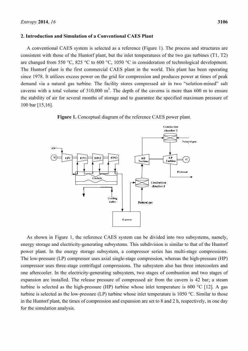
Figure 1. Conceptual diagram of the reference CAES power plant.
As shown in Figure 1, the reference CAES system can be divided into two subsystems, namely,
energy storage and electricity-generating subsystems. This subdivision is similar to that of the Huntorf
power plant. In the energy storage subsystem, a compressor series has multi-stage compressions.
The low-pressure (LP) compressor uses axial single-stage compression, whereas the high-pressure (HP)
compressor uses three-stage centrifugal compressions. The subsystem also has three intercoolers and
one aftercooler. In the electricity-generating subsystem, two stages of combustion and two stages of
expansion are installed. The release pressure of compressed air from the cavern is 42 bar; a steam
turbine is selected as the high-pressure (HP) turbine whose inlet temperature is 600 °C [12]. A gas
turbine is selected as the low-pressure (LP) turbine whose inlet temperature is 1050 °C. Similar to those
in the Huntorf plant, the times of compression and expansion are set to 8 and 2 h, respectively, in one day
for the simulation analysis.
Entropy 2014, 16 3107
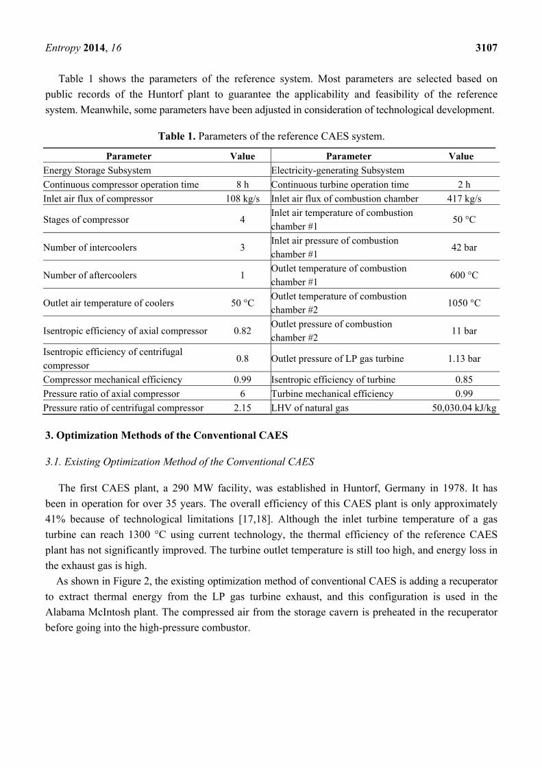
Table 1 shows the parameters of the reference system. Most parameters are selected based on
public records of the Huntorf plant to guarantee the applicability and feasibility of the reference
system. Meanwhile, some parameters have been adjusted in consideration of technological development.
Table 1. Parameters of the reference CAES system.
Parameter Value Parameter Value
Energy Storage Subsystem Electricity-generating Subsystem
Continuous compressor operation time 8 h Continuous turbine operation time 2 h
Inlet air flux of compressor 108 kg/s Inlet air flux of combustion chamber 417 kg/s
Stages of compressor 4 Inlet air temperature of combustion chamber #1
50 °C
Number of intercoolers 3 Inlet air pressure of combustion chamber #1
42 bar
Number of aftercoolers 1 Outlet temperature of combustion chamber #1
600 °C
Outlet air temperature of coolers 50 °C Outlet temperature of combustion chamber #2
1050 °C
Isentropic efficiency of axial compressor 0.82 Outlet pressure of combustion chamber #2
11 bar
Isentropic efficiency of centrifugal compressor
0.8 Outlet pressure of LP gas turbine 1.13 bar
Compressor mechanical efficiency 0.99 Isentropic efficiency of turbine 0.85
Pressure ratio of axial compressor 6 Turbine mechanical efficiency 0.99
Pressure ratio of centrifugal compressor 2.15 LHV of natural gas 50,030.04 kJ/kg
3. Optimization Methods of the Conventional CAES
3.1. Existing Optimization Method of the Conventional CAES
The first CAES plant, a 290 MW facility, was established in Huntorf, Germany in 1978. It has
been in operation for over 35 years. The overall efficiency of this CAES plant is only approximately
41% because of technological limitations [17,18]. Although the inlet turbine temperature of a gas
turbine can reach 1300 °C using current technology, the thermal efficiency of the reference CAES
plant has not significantly improved. The turbine outlet temperature is still too high, and energy loss in
the exhaust gas is high.
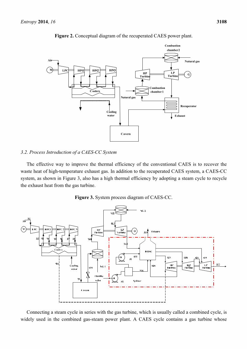
As shown in Figure 2, the existing optimization method of conventional CAES is adding a recuperator
to extract thermal energy from the LP gas turbine exhaust, and this configuration is used in the
Alabama McIntosh plant. The compressed air from the storage cavern is preheated in the recuperator
before going into the high-pressure combustor.
Entropy 2014, 16 3108
Figure 2. Conceptual diagram of the recuperated CAES power plant.
M
Air
Cavern
Cooling water
C oolers
GLP Turbine
HP Turbine
LPC HPC1 HPC2 HPC3
Exhaust
Natural gas
Combustion chamber 1
Natural gas
Combustion
chamber 2
Recuperator
3.2. Process Introduction of a CAES-CC System
The effective way to improve the thermal efficiency of the conventional CAES is to recover the
waste heat of high-temperature exhaust gas. In addition to the recuperated CAES system, a CAES-CC
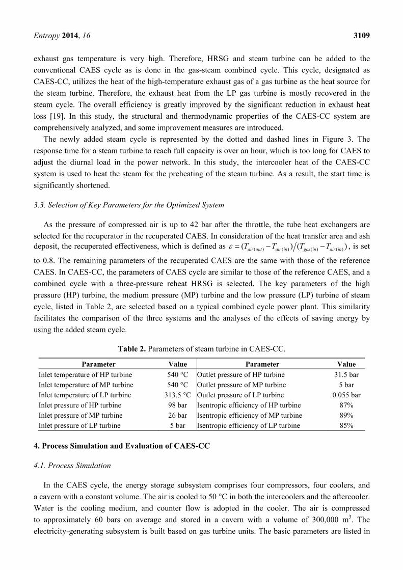
system, as shown in Figure 3, also has a high thermal efficiency by adopting a steam cycle to recycle
the exhaust heat from the gas turbine.
Figure 3. System process diagram of CAES-CC.
Connecting a steam cycle in series with the gas turbine, which is usually called a combined cycle, is
widely used in the combined gas-steam power plant. A CAES cycle contains a gas turbine whose
Entropy 2014, 16 3109
exhaust gas temperature is very high. Therefore, HRSG and steam turbine can be added to the
conventional CAES cycle as is done in the gas-steam combined cycle. This cycle, designated as
CAES-CC, utilizes the heat of the high-temperature exhaust gas of a gas turbine as the heat source for
the steam turbine. Therefore, the exhaust heat from the LP gas turbine is mostly recovered in the
steam cycle. The overall efficiency is greatly improved by the significant reduction in exhaust heat
loss [19]. In this study, the structural and thermodynamic properties of the CAES-CC system are
comprehensively analyzed, and some improvement measures are introduced.
The newly added steam cycle is represented by the dotted and dashed lines in Figure 3. The
response time for a steam turbine to reach full capacity is over an hour, which is too long for CAES to
adjust the diurnal load in the power network. In this study, the intercooler heat of the CAES-CC
system is used to heat the steam for the preheating of the steam turbine. As a result, the start time is
significantly shortened.
3.3. Selection of Key Parameters for the Optimized System
As the pressure of compressed air is up to 42 bar after the throttle, the tube heat exchangers are
selected for the recuperator in the recuperated CAES. In consideration of the heat transfer area and ash deposit, the recuperated effectiveness, which is defined as ( ) ( ) ( ) ( )( ) ( )air out air in gas in air inT T T T , is set
to 0.8. The remaining parameters of the recuperated CAES are the same with those of the reference
CAES. In CAES-CC, the parameters of CAES cycle are similar to those of the reference CAES, and a
combined cycle with a three-pressure reheat HRSG is selected. The key parameters of the high
pressure (HP) turbine, the medium pressure (MP) turbine and the low pressure (LP) turbine of steam
cycle, listed in Table 2, are selected based on a typical combined cycle power plant. This similarity
facilitates the comparison of the three systems and the analyses of the effects of saving energy by
using the added steam cycle.
Table 2. Parameters of steam turbine in CAES-CC.
Parameter Value Parameter Value
Inlet temperature of HP turbine 540 °C Outlet pressure of HP turbine 31.5 bar Inlet temperature of MP turbine 540 °C Outlet pressure of MP turbine 5 bar Inlet temperature of LP turbine 313.5 °C Outlet pressure of LP turbine 0.055 bar Inlet pressure of HP turbine 98 bar Isentropic efficiency of HP turbine 87% Inlet pressure of MP turbine 26 bar Isentropic efficiency of MP turbine 89% Inlet pressure of LP turbine 5 bar Isentropic efficiency of LP turbine 85%
4. Process Simulation and Evaluation of CAES-CC
4.1. Process Simulation
In the CAES cycle, the energy storage subsystem comprises four compressors, four coolers, and
a cavern with a constant volume. The air is cooled to 50 °C in both the intercoolers and the aftercooler.
Water is the cooling medium, and counter flow is adopted in the cooler. The air is compressed
to approximately 60 bars on average and stored in a cavern with a volume of 300,000 m3. The
electricity-generating subsystem is built based on gas turbine units. The basic parameters are listed in
Entropy 2014, 16 3110
Table 1. The compressed air released from the air storage cavern is mixed with natural gas in the
combustion chamber. Before flowing into the HP turbine, the mixed gas is heated to 600 °C. Similarly,
a certain amount of natural gas is also mixed with the gas exhausted from the HP turbine. Then, the
mixed gas is heated to 1050 °C before entering the LP turbine.
In the CC cycle, the electricity-generating subsystem is based on a three-pressure reheat HRSG and
a steam turbine. The steam produced in the HRSG is divided into two parts with different pressures
and then fed into the HP steam turbine and the LP steam turbine, respectively. As shown in Figure 2,
the steam from the HP steam turbine is injected into the HRSG for recycling before going into the MP
steam turbine, and the steam from the MP steam turbine is directly injected into the LP steam turbine.
The basic parameters of the steam turbine are listed in Table 2.
The CAES-CC system, along with the recuperated CAES and the reference CAES systems, is
simulated using the commercial software ASPEN PLUS. During the physical and chemical processes
involved in the simulation, the Peng–Robinson base method is adopted for all the equations of state.
The thermodynamic process in each combustion chamber and gas turbine is regarded as an adiabatic
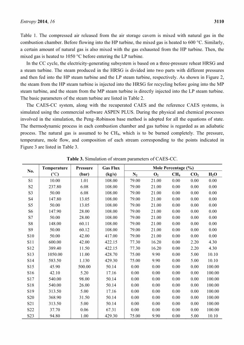
process. The natural gas is assumed to be CH4, which is to be burned completely. The pressure,
temperature, mole flow, and composition of each stream corresponding to the points indicated in
Figure 3 are listed in Table 3.
Table 3. Simulation of stream parameters of CAES-CC.
No. Temperature
(°C) Pressure
(bar) Gas Flux
(kg/s)
Mole Percentage (%)
N2 O2 CH4 CO2 H2O
S1 10.00 1.01 108.00 79.00 21.00 0.00 0.00 0.00 S2 237.80 6.08 108.00 79.00 21.00 0.00 0.00 0.00 S3 50.00 6.08 108.00 79.00 21.00 0.00 0.00 0.00 S4 147.80 13.05 108.00 79.00 21.00 0.00 0.00 0.00 S5 50.00 13.05 108.00 79.00 21.00 0.00 0.00 0.00 S6 147.90 28.00 108.00 79.00 21.00 0.00 0.00 0.00 S7 50.00 28.00 108.00 79.00 21.00 0.00 0.00 0.00 S8 148.00 60.11 108.00 79.00 21.00 0.00 0.00 0.00 S9 50.00 60.12 108.00 79.00 21.00 0.00 0.00 0.00 S10 50.00 42.00 417.00 79.00 21.00 0.00 0.00 0.00 S11 600.00 42.00 422.15 77.30 16.20 0.00 2.20 4.30 S12 389.40 11.50 422.15 77.30 16.20 0.00 2.20 4.30 S13 1050.00 11.00 428.70 75.00 9.90 0.00 5.00 10.10 S14 583.50 1.130 429.30 75.00 9.90 0.00 5.00 10.10 S15 45.90 500.00 50.14 0.00 0.00 0.00 0.00 100.00 S16 42.10 5.20 17.16 0.00 0.00 0.00 0.00 100.00 S17 540.00 98.00 50.14 0.00 0.00 0.00 0.00 100.00 S18 540.00 26.00 50.14 0.00 0.00 0.00 0.00 100.00 S19 313.50 5.00 17.16 0.00 0.00 0.00 0.00 100.00 S20 368.90 31.50 50.14 0.00 0.00 0.00 0.00 100.00 S21 313.50 5.00 50.14 0.00 0.00 0.00 0.00 100.00 S22 37.70 0.06 67.31 0.00 0.00 0.00 0.00 100.00 S23 94.80 1.00 429.30 75.00 9.90 0.00 5.00 10.10
Entropy 2014, 16 3111
The volume of the cavern involved in this study is constant. The air pressure inside the cavern
increases along with the compressed air injected continuously into the cavern in the low-load period.
This procedure requires an amplitude variation in compressor outlet air pressure to effectively store air.
Considering the limitation of ASPEN PLUS, we assume that the compressed air pressure (S9) entering
the cavern is approximately 60 bar on average. The discharge pressure of the cavern and the power
output of the gas turbine both decrease as the compressed air is continuously discharged from the
cavern in the load period. The gas turbine driven by sliding air pressure is not suitable because of the
load characteristics in its supply network. Thus, the air (S10) from the cavern is throttled down to the
HP gas turbine inlet pressure before it is fed into the combustion chamber.
4.2. Evaluation Criteria
The CAES plant has two energy inputs (i.e., electric energy and fuel during the charging and
discharging phases, respectively) with different qualities. The evaluation criteria for CAES plants
differ from those usually applied for conventional power plants. For example, specific fuel consumption
cannot identify the thermodynamic merits of a CAES plant as in a conventional power cycle. Thus,
some evaluation criteria are introduced [20–22].
(1) Energy rate
Energy rate (ER) represents the ratio of pumping energy at the off-peak period to the generated
energy during the peak period:
t
c
W
WER (1)
Although ER does not account for fuel consumption, it is unique to CAES plants. Therefore, ER is
used as another performance parameter in addition to Wt, which is the net electric energy output during
the discharge phase.
(2) Heat rate
Heat rate (HR) represents the kilowatt hour of heat required to produce a kilowatt hour of energy.
It is written as:
t
f
W
QHR (2)
where Qf is the total fuel energy (kWh) used in the combustors and boilers during the generation period.
(3) Overall efficiency
The output from a CAES plant is work. It may be compared with input energy to the plant consisting
of natural gas and compressor work:
cf
tee WQ
W
(3)
This equation may be seen as an expression of storage efficiency. However, it may be questionable.
It consists of two energy types that are consumed by different parts of the process at different periods.
Entropy 2014, 16 3112
Fuel cannot be seen as part of electricity storage but is only required because of the heating of the air
to the turbine.
(4) Efficiency of electricity storage
Efficiency of electricity storage may be defined as:
fsysc
tes QW
W
(4)
System efficiency ηsys reflects the efficiency of electricity production in the energy system. Its value
depends on which system the CAES plant uses. For a gas turbine power plant, the value is between
45% and 58%. Accordingly, the ηsys of this CAES-CC is assumed to be 50%.
4.3. Thermal Performance Analysis
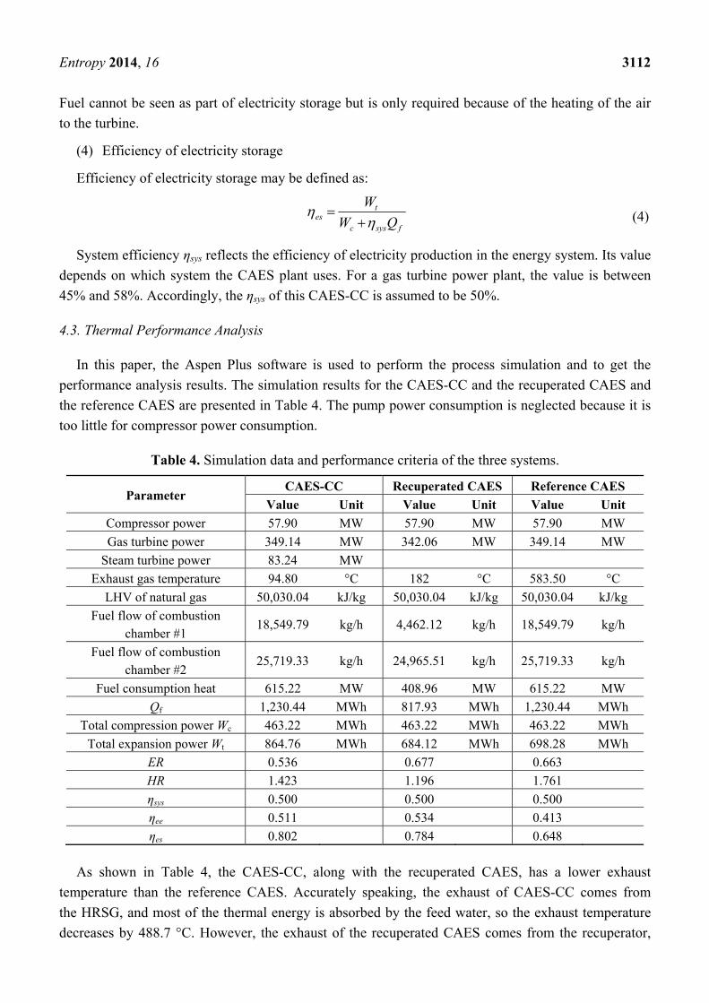
In this paper, the Aspen Plus software is used to perform the process simulation and to get the
performance analysis results. The simulation results for the CAES-CC and the recuperated CAES and
the reference CAES are presented in Table 4. The pump power consumption is neglected because it is
too little for compressor power consumption.
Table 4. Simulation data and performance criteria of the three systems.
Parameter CAES-CC Recuperated CAES Reference CAES
Value Unit Value Unit Value Unit
Compressor power 57.90 MW 57.90 MW 57.90 MW
Gas turbine power 349.14 MW 342.06 MW 349.14 MW
Steam turbine power 83.24 MW
Exhaust gas temperature 94.80 °C 182 °C 583.50 °C
LHV of natural gas 50,030.04 kJ/kg 50,030.04 kJ/kg 50,030.04 kJ/kg
Fuel flow of combustion chamber #1
18,549.79 kg/h 4,462.12 kg/h 18,549.79 kg/h
Fuel flow of combustion chamber #2
25,719.33 kg/h 24,965.51 kg/h 25,719.33 kg/h
Fuel consumption heat 615.22 MW 408.96 MW 615.22 MW
Qf 1,230.44 MWh 817.93 MWh 1,230.44 MWh
Total compression power Wc 463.22 MWh 463.22 MWh 463.22 MWh
Total expansion power Wt 864.76 MWh 684.12 MWh 698.28 MWh
ER 0.536 0.677 0.663
HR 1.423 1.196 1.761
ηsys 0.500 0.500 0.500
ηee 0.511 0.534 0.413
ηes 0.802 0.784 0.648
As shown in Table 4, the CAES-CC, along with the recuperated CAES, has a lower exhaust
temperature than the reference CAES. Accurately speaking, the exhaust of CAES-CC comes from
the HRSG, and most of the thermal energy is absorbed by the feed water, so the exhaust temperature
decreases by 488.7 °C. However, the exhaust of the recuperated CAES comes from the recuperator,
Entropy 2014, 16 3113
and most of the thermal energy is absorbed by the compressed air, so the exhaust temperature decreases
by 401.5 °C. As far as the system performance of the three systems are concerned, both CAES-CC and
the recuperated CAES are superior to the reference CAES. Although CAES-CC has recycled more
exhaust thermal energy than the recuperated CAES, the energy loss of the steam cycle in CAES-CC is
higher than the energy loss of the heat recovery device in the recuperated CAES, so the overall
efficiency ηee of CAES-CC is lower than that of the recuperated CAES.
As for the efficiency of electricity storage, the ηes of CAES-CC is higher than that of the
recuperated CAES. From the structure and the system process of the two systems, it is found that
their energy-saving methods are essentially different. The LP gas turbine exhaust is used for
generating extra electricity by the steam cycle in CAES-CC, so the ER of CAES-CC is significantly
decreased. However, the recuperated CAES utilizes the LP gas turbine exhaust to heat the compressed
air, so the HR of the recuperated CAES is significantly decreased. Decreasing the ER or the HR can
either improve the ηes of the CAES system. However, from the perspective of the quality of energy,
electricity is more superior to the chemical energy of the fuel, and there is an energy loss in the energy
conversion process from thermal energy to electricity, on that account, compared with decreasing the
HR of CAES, decreasing the ER of CAES is more favorable to improve the efficiency of electricity
storage of the CAES system.
In fact, for the CAES plant with a low-power gas turbine, such as the McIntosh plant, adding a
recuperator is relatively easy to implement in the engineering application. However, the proposed
system which uses a gas turbine with large capacity and high parameters has a larger scale than the
McIntosh CAES plant. If a recuperated CAES operates under the high parameter condition shown in
Table 1, the heat exchange capacity will be approximately 188 MW. Considering the recuperator
selected in the recuperated CAES is gas-air heat transfer mode, the estimated heat transfer area of the
recuperator is over 1.0 × 10⁴ m2. Such large heat transfer area will lead to large volume and high
investment of the recuperator. Furthermore, it will also cause a great pressure drop for the recuperator
and the outlet pressure of LP gas turbine will increase accordingly, which results in a power output
decrease of the LP gas turbine. The gas turbine power output of the mentioned recuperated CAES will
decrease by 0.365 MW if the LP gas turbine outlet pressure increases by 0.5 kPa.
In conclusion, with high exhaust temperature and large exhaust flow of the gas turbine, the recuperated
CAES is difficult to be implemented in engineering application. However, the steam turbine and HRSG
adopted in CAES-CC are technically mature, therefore, CAES-CC is more suitable under the high
parameter conditions.
4.4. System Analysis according to the Second Law of Thermodynamics
As mentioned above, the thermodynamic analysis is based on the first law of thermodynamics, that
is, only considering the energy balance in the “amount” and not taken the “grade” of energy into
account. To further analyze the thermodynamic performance of the system, it is necessary to study
the system based on the second law of thermodynamics. The entropy generation and the exergy
destruction are the measurement indicators of the thermodynamic irreversibility. Through the analysis
of the entropy generation and the exergy destruction, the irreversible loss of thermal process can be
Entropy 2014, 16 3114
measured. The relationship between the entropy generation and the exergy destruction can be
described by the Gouy-Stodola equation:
isor STI 0 (5)
In this equation, Ir represents exergy destruction, T0 represents the environment tempreture, and
△Siso represents entropy generation. It is easy to see that the exergy destruction can demonstrate
the entropy generation. It is common to conduct exergy analysis based on the second law of
thermodynamics [23,24]. Therefore, to reveal the internal phenomena of the CAES-CC system, an
exergy analysis is performed for the CAES-CC and reference CAES. Assuming no chemical reaction
occurs and neglecting the kinematic energy effects, the exergy of air or gas stream can be expressed as:
)()( 000X SSTHHE (6)
where H and S are enthalpy and entropy of the steam, respectively, and the subscript 0 indicates
that the properties are taken at the environmental temperature and pressure (T0 = 25 °C, P0 = 101 kPa).
The general exergy balance of the system components can be expressed as:
XX(loss))out()out(X)in()in(X EEWEWE (7)
In Equation (7), ∆EX refers to the exergy destruction, EX(in) and W(in) refer to the exergy input
and the power input, respectively, EX(out) and W(out) denote the exergy output and the power output,
respectively. EX(loss) represents the exergy loss caused by energy loss. However, in this paper, there is
very little heat dissipation during the energy conversion process, therefore, the simulation models of
the systems are considered as adiabatic process and the “energy loss” is considered as zero. Therefore,
EX(loss) in the energy conversion process is zero, and then the general exergy balance of the system
components can be expressed in the following rate form:
X)out()out(X)in()in(X EWEWE (8)
The exergy destruction within a component of the energy conversion system can be derived from
the exergy balance equation. In this paper, the CAES systems are divided into several parts to conduct
a detailed study on the exergy analysis. And the exergy analysis of all the equipments mentioned in the
article is conducted according to the general exergy balance. Table 5 lists the exergy destruction within
different components of the energy conversion system.
Based on the aforementioned foundation, the exergy analyses results of CAES-CC and conventional
CAES are presented in Table 6. The exergy analysis is based on the assumption that the same quantity
of electric power and natural gas is consumed in the CAES-CC and reference systems. In consideration
of the non-synchronization between electricity consumption and power generation, the exergy analysis
is based on a ten-hour cycle of the operation of the CAES-CC system.
As shown in Table 6, the exergy efficiency of the CAES-CC system is 49.43%, which is 9.51%
higher than that of the reference system. Comparing the exergy distributions of the CAES-CC system
with those of the reference system in Table 6, it is shown that the exergy of the power production
increases and that the total exergy destruction of the CAES-CC system obviously decreases. The main
reduction in exergy destruction is caused by the HRSG and steam turbine. The detailed distribution of
the exergy destruction of these two units is given in Table 6.
Entropy 2014, 16 3115
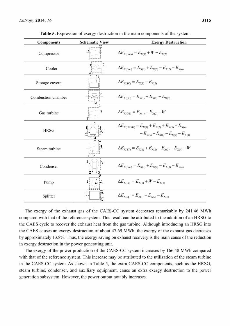
Table 5. Expression of exergy destruction in the main components of the system.
Components Schematic View Exergy Destruction
Compressor X(2)X(1)X(Com) EWEE
Cooler X(4)X(2)X(3)X(1)X(Coo) EEEEE
Storage cavern X(2)X(1)X(SC) EEE
Combustion chamber X(3)X(2)X(1)X(CC) EEEE
Gas turbine WEEE X(2)X(1)X(GT)
HRSG X(8)X(7)X(6)X(5)
X(4)X(3)X(2))X(1X(HRSG)
EEEE
EEEEE
Steam turbine WEEEEE X(4)X(3)X(2)X(1)X(ST)
Condenser X(4)X(3)X(2)X(1)X(Con) EEEEE
Pump X(2)X(1)X(Pu) EWEE
Splitter X(3)X(2)X(1)X(Sp) EEEE
The exergy of the exhaust gas of the CAES-CC system decreases remarkably by 241.46 MWh
compared with that of the reference system. This result can be attributed to the addition of an HRSG to
the CAES cycle to recover the exhaust heat from the gas turbine. Although introducing an HRSG into
the CAES causes an exergy destruction of about 47.69 MWh, the exergy of the exhaust gas decreases
by approximately 13.8%. Thus, the exergy saving on exhaust recovery is the main cause of the reduction
in exergy destruction in the power generating unit.
The exergy of the power production of the CAES-CC system increases by 166.48 MWh compared
with that of the reference system. This increase may be attributed to the utilization of the steam turbine
in the CAES-CC system. As shown in Table 5, the extra CAES-CC components, such as the HRSG,
steam turbine, condenser, and auxiliary equipment, cause an extra exergy destruction to the power
generation subsystem. However, the power output notably increases.
Entropy 2014, 16 3116
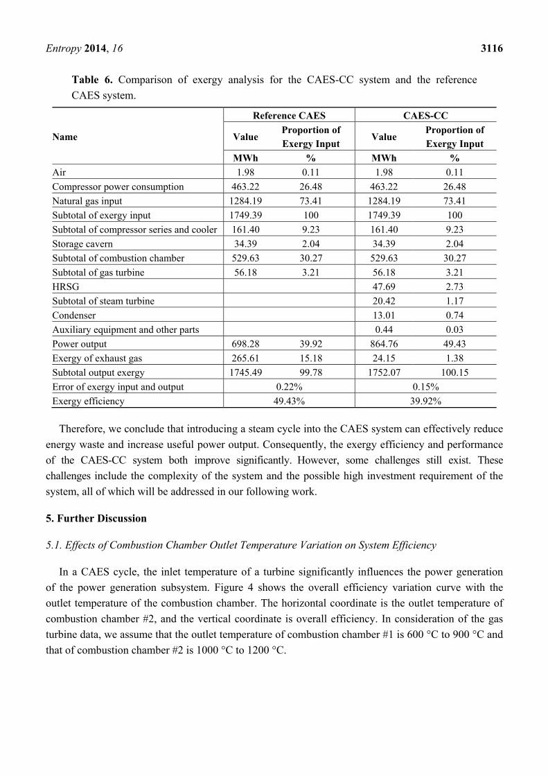
Table 6. Comparison of exergy analysis for the CAES-CC system and the reference
CAES system.
Name
Reference CAES CAES-CC
Value Proportion of Exergy Input
Value Proportion of Exergy Input
MWh % MWh %
Air 1.98 0.11 1.98 0.11
Compressor power consumption 463.22 26.48 463.22 26.48
Natural gas input 1284.19 73.41 1284.19 73.41
Subtotal of exergy input 1749.39 100 1749.39 100
Subtotal of compressor series and cooler 161.40 9.23 161.40 9.23
Storage cavern 34.39 2.04 34.39 2.04
Subtotal of combustion chamber 529.63 30.27 529.63 30.27
Subtotal of gas turbine 56.18 3.21 56.18 3.21
HRSG 47.69 2.73
Subtotal of steam turbine 20.42 1.17
Condenser 13.01 0.74
Auxiliary equipment and other parts 0.44 0.03
Power output 698.28 39.92 864.76 49.43
Exergy of exhaust gas 265.61 15.18 24.15 1.38
Subtotal output exergy 1745.49 99.78 1752.07 100.15
Error of exergy input and output 0.22% 0.15%
Exergy efficiency 49.43% 39.92%
Therefore, we conclude that introducing a steam cycle into the CAES system can effectively reduce
energy waste and increase useful power output. Consequently, the exergy efficiency and performance
of the CAES-CC system both improve significantly. However, some challenges still exist. These
challenges include the complexity of the system and the possible high investment requirement of the
system, all of which will be addressed in our following work.
5. Further Discussion
5.1. Effects of Combustion Chamber Outlet Temperature Variation on System Efficiency
In a CAES cycle, the inlet temperature of a turbine significantly influences the power generation
of the power generation subsystem. Figure 4 shows the overall efficiency variation curve with the
outlet temperature of the combustion chamber. The horizontal coordinate is the outlet temperature of
combustion chamber #2, and the vertical coordinate is overall efficiency. In consideration of the gas
turbine data, we assume that the outlet temperature of combustion chamber #1 is 600 °C to 900 °C and
that of combustion chamber #2 is 1000 °C to 1200 °C.
Entropy 2014, 16 3117
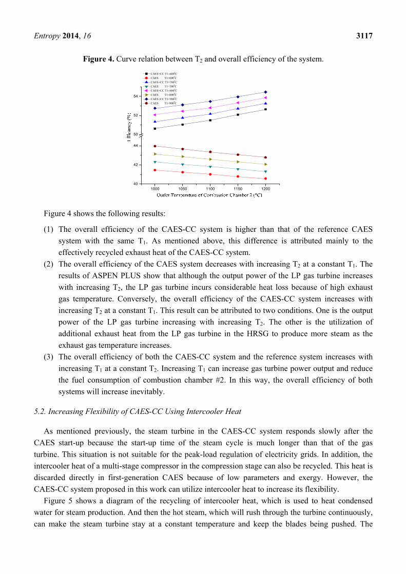
Figure 4. Curve relation between T2 and overall efficiency of the system.
1000 1050 1100 1150 120040
42
44
50
52
54
CAES+CC T1=6000C
CAES T1=6000C
CAES+CC T1=7000C
CAES T1=7000C
CAES+CC T1=8000C
CAES T1=8000C
CAES+CC T1=9000C
CAES T1=9000C
Figure 4 shows the following results:
(1) The overall efficiency of the CAES-CC system is higher than that of the reference CAES
system with the same T1. As mentioned above, this difference is attributed mainly to the
effectively recycled exhaust heat of the CAES-CC system.
(2) The overall efficiency of the CAES system decreases with increasing T2 at a constant T1. The
results of ASPEN PLUS show that although the output power of the LP gas turbine increases
with increasing T2, the LP gas turbine incurs considerable heat loss because of high exhaust
gas temperature. Conversely, the overall efficiency of the CAES-CC system increases with
increasing T2 at a constant T1. This result can be attributed to two conditions. One is the output
power of the LP gas turbine increasing with increasing T2. The other is the utilization of
additional exhaust heat from the LP gas turbine in the HRSG to produce more steam as the
exhaust gas temperature increases.
(3) The overall efficiency of both the CAES-CC system and the reference system increases with
increasing T1 at a constant T2. Increasing T1 can increase gas turbine power output and reduce
the fuel consumption of combustion chamber #2. In this way, the overall efficiency of both
systems will increase inevitably.
5.2. Increasing Flexibility of CAES-CC Using Intercooler Heat
As mentioned previously, the steam turbine in the CAES-CC system responds slowly after the
CAES start-up because the start-up time of the steam cycle is much longer than that of the gas
turbine. This situation is not suitable for the peak-load regulation of electricity grids. In addition, the
intercooler heat of a multi-stage compressor in the compression stage can also be recycled. This heat is
discarded directly in first-generation CAES because of low parameters and exergy. However, the
CAES-CC system proposed in this work can utilize intercooler heat to increase its flexibility.
Figure 5 shows a diagram of the recycling of intercooler heat, which is used to heat condensed
water for steam production. And then the hot steam, which will rush through the turbine continuously,
can make the steam turbine stay at a constant temperature and keep the blades being pushed. The
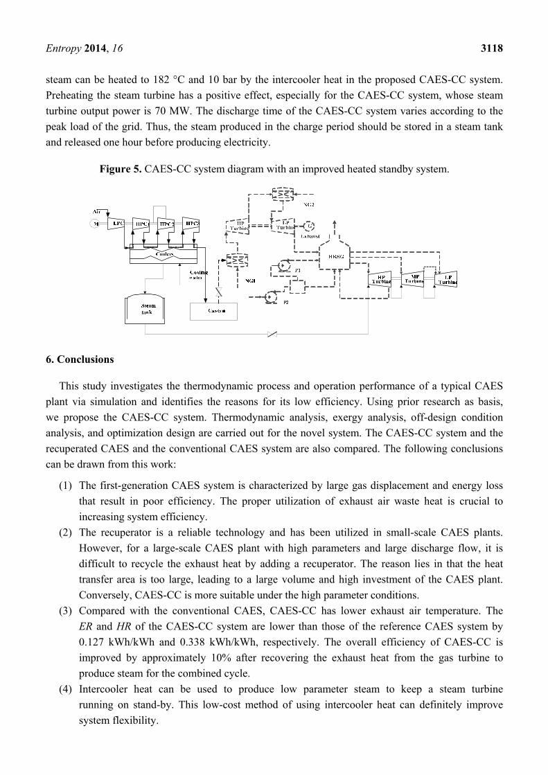
Entropy 2014, 16 3118
steam can be heated to 182 °C and 10 bar by the intercooler heat in the proposed CAES-CC system.
Preheating the steam turbine has a positive effect, especially for the CAES-CC system, whose steam
turbine output power is 70 MW. The discharge time of the CAES-CC system varies according to the
peak load of the grid. Thus, the steam produced in the charge period should be stored in a steam tank
and released one hour before producing electricity.
Figure 5. CAES-CC system diagram with an improved heated standby system.
6. Conclusions
This study investigates the thermodynamic process and operation performance of a typical CAES
plant via simulation and identifies the reasons for its low efficiency. Using prior research as basis,
we propose the CAES-CC system. Thermodynamic analysis, exergy analysis, off-design condition
analysis, and optimization design are carried out for the novel system. The CAES-CC system and the
recuperated CAES and the conventional CAES system are also compared. The following conclusions
can be drawn from this work:
(1) The first-generation CAES system is characterized by large gas displacement and energy loss
that result in poor efficiency. The proper utilization of exhaust air waste heat is crucial to
increasing system efficiency.
(2) The recuperator is a reliable technology and has been utilized in small-scale CAES plants.
However, for a large-scale CAES plant with high parameters and large discharge flow, it is
difficult to recycle the exhaust heat by adding a recuperator. The reason lies in that the heat
transfer area is too large, leading to a large volume and high investment of the CAES plant.
Conversely, CAES-CC is more suitable under the high parameter conditions.
(3) Compared with the conventional CAES, CAES-CC has lower exhaust air temperature. The
ER and HR of the CAES-CC system are lower than those of the reference CAES system by
0.127 kWh/kWh and 0.338 kWh/kWh, respectively. The overall efficiency of CAES-CC is
improved by approximately 10% after recovering the exhaust heat from the gas turbine to
produce steam for the combined cycle.
(4) Intercooler heat can be used to produce low parameter steam to keep a steam turbine
running on stand-by. This low-cost method of using intercooler heat can definitely improve
system flexibility.
Entropy 2014, 16 3119
Recovering gas turbine exhaust air heat is important in the design and optimization of a CAES plant.
Combining a CAES system with a steam turbine increases overall efficiency and system performance.
The proposed CAES-CC system serves as a reference for improving the utility pattern of CAES.
Further studies must be conducted to make CAES-CC suitable for the national conditions of China.
Acknowledgements
The paper is supported by National Nature Science Fund of China (No. 51276059) and the
111 Project (B12034).
Author Contributions
In this paper, Wenyi Liu provides the original idea and constructs its framework, and is responsible
for drafting and revising the whole paper; Linzhi Liu conducts the detailed calculation, simulation and
contributes to revising the paper; Luyao Zhou devotes efforts to revising the paper; Jian Huang
completes the further discussion of the proposed system; Yuwen Zhang devotes efforts to the writing
of the exergy analysis; Gang Xu and Yongping Yang are the main technical guidances and give some
valuable comments on revising the paper.
Conflicts of Interest
The authors declare no conflict of interest.
References
1. Liu, W.-Y.; Yang, Y.-P.; Zhang, X.G.; Xin, Y.B. Present situation and development trend of
compressed air energy storage (CAES) power plant. Shandong Electr. Power 2007, 2, 10–14. (in
Chinese)
2. Wind Power. Available online: http://en.wikipedia.org/wiki/Wind_power#cite_note-gws-2012–46
(accessed on 12 December 2013).
3. The Central People’s Government of the People’s Republic of China. Available online: http://
www.gov.cn/jrzg/2013-08/26/content_2474123.htm (accessed on 14 December 2013). (in Chinese)
4. White Paper on the Research of the Energy Storage Industry 2013. Available online: http://
www1.cnesa.org/do/bencandy.php?fid=84&id=2128 (accessed on 23 August 2013). (in Chinese)
5. Rastler, D.M. Electricity Energy Storage Technology Options: A White Paper Primer on Applications,
Costs and Benefits; Electric Power Research Institute (EPRI): Palo Alto, CA, USA, 2010.
6. National Development and Reform Commission. China’s Twelfth Five-Year Plan (2011–2015).
In Proceedings of the Fifth Plenary Session of the 17th CPC Central Committee, Beijing, China, 18
October 2010 (in Chinese).
7. Party of China’s Conditions on the Construction of Pumped Storage Power Station by the End of
2012. Available online: http://news.bjx.com.cn/html/20130912/459422.shtml (accessed on 12
December 2013) (in Chinese).
8. Eckroad, S.; Gyuk. I. EPRI-DOE Handbook of Energy Storage for Transmission & Distribution
Applications; Electric Power Research Institute (EPRI): Palo Alto, CA, USA, 2003.
Entropy 2014, 16 3120
9. Bullough, C.; Gatzen, C.; Jakiel, C.; Koller, M.; Nowi, A.; Zunft, S. Advanced adiabatic
compressed air energy storage for the integration of wind energy. In Proceedings of the European
Wind Energy Conference (EWEC) 2004, London, UK, 22–25 November 2004.
10. Zafirakis, D.; Kaldellis, J.K. Economic evaluation of the dual mode CAES solution for increased
wind energy contribution in autonomous island networks. Energy Policy 2009, 37, 1958–1969.
11. Denholm, P. Improving the technical, environmental and social performance of wind energy
systems using biomass-based energy storage. Renew. Energy 2006, 31, 1355–1370.
12. Kim, Y.M.; Daniel, F. Energy and exergy analysis of a micro-compressed air energy storage and
air cycle heating and cooling system. Energy 2010, 35, 213–220.
13. Nakhamkin, M. New compressed air energy storage concept improves the profitability of existing
simple cycle, combined cycle, wind energy, and landfill gas power plants. In Proceedings of the
ASME Turbo Expo 2004: Power for Land, Sea, and Air, Vienna, Austria, 14–17 June 2004;
American Society of Mechanical Engineers: New York, NY, USA, 2004.
14. Nakhamkin, M. Conversion of Combined Cycle Power Plant to Compressed Air Energy Storage
Power Plant. U.S. Patent No. 7640643, 5 January 2010.
15. Huntorf Air Storage Gas Turbine Power Plant. Available online: http://www.kraftwerk-
wilhelmshaven.com/pages/ekw_de/Kraftwerk_Wilhelmshaven/Mediencenter/_documents/BBC-
Huntorf_engl.pdf (accessed on 3 June 2014).
16. Crotogino, F.; Mohmeyer, K.U.; Scharf, R. Huntorf CAES: More than 20 Years of Successful
Operation. In Proceedings of the Solution Mining Research Institute (SMRI) Spring Meeting
2001, Orlando, FL, USA, 15–18 April 2001; pp. 351–357.
17. Compressed Air Energy Storage Power Plant. Available online: http://www.bine.info/fileadmin/
content/Publikationen/Englische_Infos/projekt_0507_engl_internetx.pdf (accessed on 3 June 2014).
18. Pickard, W.F.; Hansing, N.J.; Shen, A.Q. Can large-scale advanced-adiabatic compressed air
energy storage be justified economically in an age of sustainable energy? J. Renew. Sustain. Energy.
2009, 1, 033102.
19. Jiao, S.J. Gas-Steam Combined Cycle; Mechanical Industry Press: Beijing, China, 2004.
20. Taylor, J.; Halnes, A. Analysis Of compressed air energy storage. In Proceedings of the PCIC
Europe 2010 Conference Record, Oslo, Norway, 15–17 June 2010; pp. 1–5.
21. Elmegaard, B.; Brix, W. Efficiency of compressed air energy storage. In Proceedings of the
24th International Conference on Efficiency, Cost, Optimization, Simulation and Environmental
Impact of Energy Systems, Novi Sad, Serbia, 4–7 July 2011.
22. Najjar, Y.S.; Zaamout, M.S. Performance analysis of compressed air energy storage (CAES) plant
for dry regions. Energy Convers. Manag. 1998, 39, 1503–1511.
23. Kim, Y.M.; Lee, J.H.; Kim, S.J.; Favrat, D. Potential and evolution of compressed air energy
storage: Energy and exergy analyses. Entropy 2012, 14, 1501–1521.
24. Buffa, F.; Kemble, S.; Manfrida, G.; Milazzo, A. Exergy and exergoeconomic model of a
ground-based CAES plant for peak-load energy production. Energies 2013, 6, 1050–1067.
© 2014 by the authors; licensee MDPI, Basel, Switzerland. This article is an open access article
distributed under the terms and conditions of the Creative Commons Attribution license
(http://creativecommons.org/licenses/by/3.0/).


