Embed Size (px)
Citation preview

PM No. 9852 2467 01i
Epiroc FlexiROC T20 R Operator's instructions

2
SAFETY INSTRUCTIONS
Before starting, read all instructions carefully.
Special attention must be paid to information alongside this symbol.
Only use genuine Epiroc parts.
© Copyright 2017, Epiroc Stonetec S.r.l. Any unauthorized use or copying of the contents or any part thereof is prohibited.
This applies in particular to trademarks, model denominations, part numbers and drawings.
Epiroc Stonetec S.r.l. 12031 Bagnolo Piemonte (CN), Italy

3
Safety
Safety
Reference ………………………………………………………………………………………………………5

4
Safety

5
Safety
Reference
Note Always read the information in the Safety document before starting to use the rig or starting maintenance work.

6
Safety

7
Operator's instructions
Operator's instructions 1. General ..................................................................................................................................... 11
Foreword ................................................................................................................................... 11 Principal components ................................................................................................................ 12 General system description ........................................................................................................ 13
General description of the drill rig ......................................................................................... 13 Hydraulic pumps ................................................................................................................... 17
Hydraulic pump 1 .............................................................................................................. 17 Hydraulic pump 2 .............................................................................................................. 17 Hydraulic pump 3 .............................................................................................................. 17 Hydraulic pump 4 .............................................................................................................. 17
Air system ............................................................................................................................. 17 2.Technical data ............................................................................................................................ 18
FlexiROC T20 R ....................................................................................................................... 18 Dimensions ............................................................................................................................... 20
Dimensions ........................................................................................................................... 20 Transport dimensions ........................................................................................................ 20 Coverage area ................................................................................................................... 21 Danger zone ...................................................................................................................... 21
3. Daily checks.............................................................................................................................. 22 Foreword ................................................................................................................................... 22 Extra safety check ..................................................................................................................... 22
Safety .................................................................................................................................... 22 Check points.......................................................................................................................... 23
Before starting ........................................................................................................................... 25 Safety .................................................................................................................................... 25 Checks .................................................................................................................................. 25
Functionality test after start ....................................................................................................... 26 Checks .................................................................................................................................. 26
Function test while drilling ........................................................................................................ 27 Checks .................................................................................................................................. 27
4.Controls ..................................................................................................................................... 28 Controls .................................................................................................................................... 28
General.................................................................................................................................. 28 Remote control box ............................................................................................................... 29 Pressure gauge panel ............................................................................................................. 30 Operator panel ....................................................................................................................... 31 Menu views ........................................................................................................................... 33
Settings submenus ............................................................................................................. 33 Diagnostics submenus ....................................................................................................... 34 Options submenus ............................................................................................................. 35 Shortcuts menus ................................................................................................................ 36 Gradient meter ................................................................................................................... 38 Control panel for diesel engine .......................................................................................... 39
5. Radio box .................................................................................................................................. 42 Safety .................................................................................................................................... 42
Controls .................................................................................................................................... 43 Left-hand multifunction lever ................................................................................................ 44 Right-hand multifunction lever .............................................................................................. 45 Right-hand multifunction lever-proportional function ............................................................ 46

8
Touch buttons ........................................................................................................................... 47 Menu views ........................................................................................................................... 48
Navigation ......................................................................................................................... 48 Menu description ............................................................................................................... 49 Menus for testing ............................................................................................................... 51 Error messages .................................................................................................................. 53
Function ................................................................................................................................ 56 Time-out function .............................................................................................................. 56 Start-up ............................................................................................................................. 56 Stops ................................................................................................................................. 57 Drilling .............................................................................................................................. 57 Display heater.................................................................................................................... 58 Replacing the box .............................................................................................................. 59 Learn-link .......................................................................................................................... 59
6. Operating .................................................................................................................................. 61 Activating the remote control box ............................................................................................. 61 Diesel engine starting ................................................................................................................ 64 Stopping the diesel engine ......................................................................................................... 65 Feed Rotation ............................................................................................................................ 66
General.................................................................................................................................. 66 Upward and horizontal drilling .......................................................................................... 66 Maintenance for drilling upwards ...................................................................................... 67
Hydraulic feed rotation .......................................................................................................... 68 Safety ................................................................................................................................ 68 Operation .......................................................................................................................... 68
Tramming ................................................................................................................................. 69 Operation .............................................................................................................................. 69
Checking after tramming ........................................................................................................... 71 Tramming - General principles .................................................................................................. 71
Tramming, general ................................................................................................................ 71 Maximum permitted inclination angles during setting- up for drilling........................................ 72
Setting-up for drilling with the feeder in vertical position and centered between the wheels... 72 Setting-up for drilling with the feeder in vertical position and swung max to left ................... 72 Setting-up for drilling with the feeder in vertical position and swung max to right ................. 73 Setting-up for drilling with the feeder top in extreme position forwards, the feeder laterally vertical and centred between the wheels ................................................................................ 73 Setting-up for drilling with the feeder top in extreme position rearwards, the feeder laterally vertical and centered between the wheels ............................................................................... 73
Using the winch when tramming ............................................................................................... 74 General.................................................................................................................................. 75 Action before winching ......................................................................................................... 75 Checking the attachment of the winch cable .......................................................................... 75 Correct assembly ................................................................................................................... 76 Tramming uphill.................................................................................................................... 77 Tramming downhill ............................................................................................................... 79
7. Before drilling ........................................................................................................................... 80 Safety ........................................................................................................................................ 80 Setting up for drilling ................................................................................................................ 80 Setup for drilling - General principles........................................................................................ 82
General setup ........................................................................................................................ 82 Uphill setup ........................................................................................................................... 82 Downhill setup ...................................................................................................................... 82 Setup - Transverse incline ..................................................................................................... 83

9
8. Drilling ..................................................................................................................................... 84 Start of manual drilling.............................................................................................................. 84
Feeder adjustment during drilling .......................................................................................... 86 Checks during drilling ............................................................................................................... 87
Break loose ........................................................................................................................... 87 Break loose (applies to extension drilling) ............................................................................. 87
Rod adding ................................................................................................................................ 88 Threading .................................................................................................................................. 90 Unthreading and extracting ....................................................................................................... 91 Changing drill bit ...................................................................................................................... 93 Action in case of drilling problems ............................................................................................ 93
Drilling problems .................................................................................................................. 93 High coupling sleeve temperature .......................................................................................... 94 Difficulties in loosening the coupling sleeve .......................................................................... 94 Hole deflection ...................................................................................................................... 94
8. Options ..................................................................................................................................... 95 Electric filler pump ................................................................................................................... 95 Water flush / Water mist............................................................................................................ 96
Water flushing ....................................................................................................................... 96 Water mist ............................................................................................................................. 98
Auxiliary hydraulic fittings ....................................................................................................... 99 RAS ........................................................................................................................................ 100
Rod adding with RAS .......................................................................................................... 100 Unthreading and extracting with RAS ................................................................................. 102
Filter with Pre-Cat ................................................................................................................... 103 Use and maintenance ........................................................................................................... 104 System status ....................................................................................................................... 104 Scheduled maintenance ....................................................................................................... 105

10

11
Operator's instructions 1. General
1. General
Foreword
This instruction manual is part of the complete delivery of the drill rig. It provides information on the design and operation of the drill rig and contains advice and the measures necessary to keep the rig operational. This instruction manual is no replace- ment for thorough training on the drill rig. This instruction manual should be read in advance by all persons who are to operate or repair the drill rig or carry out maintenance on it. See separate instructions for documentation on the rock drill/rotation unit, the diesel engine and certain other components. For other questions refer to the local Epiroc company office. Addresses and tel- ephone numbers are in the Maintenance instructions.

12
Operator's instructions 1. General
Principal components
Figure: Principal components
1 Feeder 7 Dust collector (DCT) 2 Boom system 8 Compressor 3 Radiator 9 Radio receiver 4 Hydraulic oil pumps 10 Wheels 5 Diesel engine 11 Electric cabinet 6 Air tank
13
Operator's instructions 1. General
General system description
General description of the drill rig
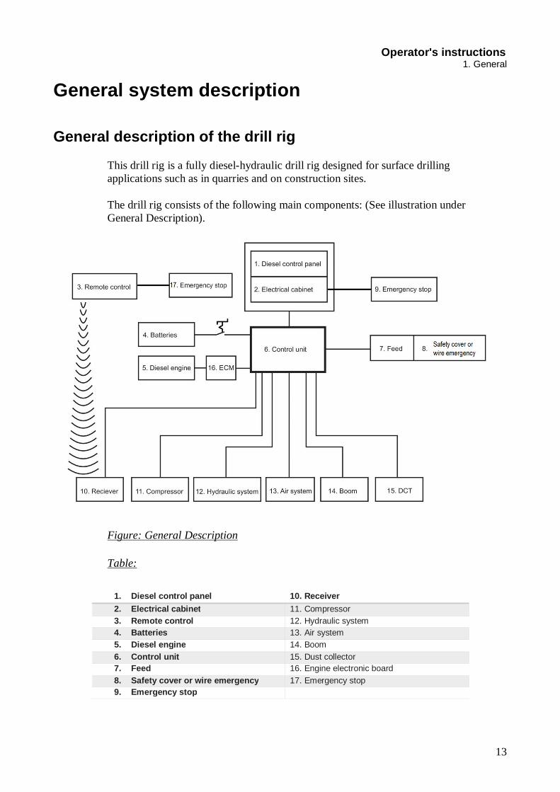
This drill rig is a fully diesel-hydraulic drill rig designed for surface drilling applications such as in quarries and on construction sites. The drill rig consists of the following main components: (See illustration under General Description).
Figure: General Description
Table:
1. Diesel control panel 10. Receiver 2. Electrical cabinet 11. Compressor 3. Remote control 12. Hydraulic system 4. Batteries 13. Air system 5. Diesel engine 14. Boom 6. Control unit 15. Dust collector 7. Feed 16. Engine electronic board 8. Safety cover or wire emergency 17. Emergency stop 9. Emergency stop

14
Operator's instructions 1. General
Wheeled chassis frame The diesel engine, chassis, dust collector, hydraulic system, air system and boom sys- tem are mounted on the wagon frame. The 4 wheels are driven by two steering axles with integrated brake. The body covers the diesel engine, the compressor, the different lubrication tanks, the valves and the hydraulic hoses. Inspection hatches facilitate access to the different machine components. All the hatches lock in the open position with a pneumatic spring. The dust collector is mounted at the back of the rig on the right-hand side.
Power pack This hydraulic drill rig is powered by a turbocharged, water-cooled diesel engine. The diesel engine is equipped with a monitoring system that includes automatic shut- down functions. The drilling carriage is driven by 2 steering axles connected to each other by a universal joint and powered by a hydraulic motor. The hydraulic pumps and the compressor are driven by a diesel engine.
Boom system The boom system consists of inner/outer boom bodies, boom head, feed holder and associated hydraulic cylinders. The boom system is controlled by directional valves for positioning the feed with the rock drill at different distances and directions.
Dust collector The hydraulically driven dust collector features automatic cleaning and consists of a filter unit, pre-separator, suction fan and suction hose.
Electrical system The 24 V electrical system is supplied with current by an alternator and two batteries. The electrical system comprises starting equipment, work lighting, electric controls and safety devices.

15
Operator's instructions 1. General
The emergency stop buttons/cables are connected in series with the diesel engine cut- out system. As soon as an emergency stop button/cable is activated, the diesel engine will be stopped immediately. Reset the emergency stop buttons before restarting the engine. The engine cannot be started while one of the emergency stops is still acti- vated. For further details, see separate wiring diagram. For details of the diesel engine, see separate diesel engine instructions.
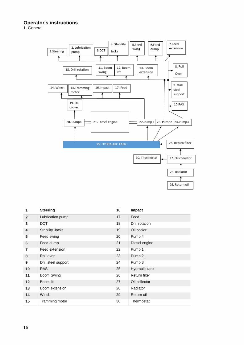
Hydraulic system The principal components of the hydraulic system comprise oil cooler, hydraulic oil tank, valves, hoses and four hydraulic pumps. The four hydraulic pumps create hydraulic pressure in order to control the different functions. The table below indicates which hydraulic pump controls which function.
Table: Description of hydraulic pump function The hydraulic oil tank is located in the centre of the drilling carriage. The radiator on the right side of the drilling carriage cools the water of the engine, the intercooler and the oil compressor. The radiator on the left side cools the hydraulic oil. (For more information, see the separate hydraulic system drawing)
PUMP NO. DESCRIPTION 1 Winch, tramming, impact, feed drill rotation
2 Boom swing, boom lift, boom extension
3 Steering, lubricating pump, dct, stability jacks, feed swing, feed dump,
feed extension, roll over, drill steel support, RAS
4 Oil cooler
16
Operator's instructions 1. General
1 Steering 16 Impact
2 Lubrication pump 17 Feed
3 DCT 18 Drill rotation
4 Stability Jacks 19 Oil cooler
5 Feed swing 20 Pump 4
6 Feed dump 21 Diesel engine
7 Feed extension 22 Pump 1
8 Roll over 23 Pump 2
9 Drill steel support 24 Pump 3
10 RAS 25 Hydraulic tank
11 Boom Swing 26 Return filter
12 Boom lift 27 Oil collector
13 Boom extension 28 Radiator
14 Winch 29 Return oil
15 Tramming motor 30 Thermostat

17
Operator's instructions 2. Technical data
Hydraulic pumps Hydraulic pump 1
Main hydraulic system pump 1 is a variable-displacement piston type. The pump supplies hydraulic power to the following functions:
Winch, tramming, impact, feed drill rotation
Hydraulic pump 2
Hydraulic pump 2 supplies hydraulic oil to provide power to the boom. Boom swing, boom lift, boom extension
Hydraulic pump 3
Hydraulic pump 3 supplies hydraulic oil to power the Steering, lubricating pump, dct, stability jacks, feed swing, feed dump, feed extension, roll over, drill steel support, RAS
Hydraulic pump 4
Hydraulic pump 4 supplies hydraulic oil to power the oil cooler motor.
Pump no.
CC
Flow (litre/min)
Pressure (bar, max.)
1
60
139
280
2
30
62
260
3
10
26
260
4
7
26
150
Air system The air system consists of the compressor with oil separator, hoses and valves. The compressor is belt-driven from the diesel engine. The compressor element is lubricated by an air-oil mixture. The mixture is separated in the oil separator. The system supplies air for flushing in the bore hole, cleaning of the dust collector filter and the rock drill lubrication system and ECL.

18
Operator's instructions 2. Technical data
2.Technical data
FlexiROC T20 R
Weight (standard equipment without drill steel) FlexiROC T20 R
Weight 5750 kg
Performance Diesel engine, Cummins QSB3.3 power output at 2400 rpm/min 82 kW 110 HP Temperature range in operation -25° C +40° C Tramming speed, max. 5 Km/h Traction force (low/high gear) 59 kN Ground clearance 220 mm Max. hydraulic pressure 290 bar Noise Level Max. engine speed (2500 giri/min.) 117 dB (A) Drilling (2500 giri/min.) 124,5 dB (A) 128 dB(A) guaranteed
Tilt angles Note
Stability is specified with respect to CE standards stipulating that rigs must not be operated on inclines steeper than 20 degrees without the use of a winch. ANGLES MUST NOT BE COMBINED!
Tilt angles for drill rig when drilling: longitudinally, max. (Downward/Upward) 20° lateral (left/right). 10° laterally, (left/right), in extreme positions. 10°
Tilt angles - tramming (in direction): downward/upward, max. without winch 20° laterally, max. (Left/Right) 10° downward/upward, with winch >20° - < 30° Max pressure on the ground of stability jacks 0.5MPa

19
Operator's instructions 2. Technical data
Hydraulic systems Hydraulic oil cooler for max. ambient temperature
40° C
Electrical system
Voltage 24V Batteries Voltage 2 x 12 V/100 Ah Front working floodlights Voltage 2 x 70 W Rear working floodlights Voltage 1 x 24V LED Column working floodlights Voltage 2 x 24V LED Generator Voltage 24 V/55 Ah
Air system
Compressor: Gardner Denver E6 Plus Max. air pressure 12 bar Free air delivery 50 l/s
Capacities
Hydraulic oil reservoir min/max level 50 / 60 l Hydraulic systems total 120 l Fuel tank 140 l Compressor oil 9 l Lubricating oil tank 6 l Diesel engine oil 8,5 l Engine cooling system 15 l
Miscellaneous
Fire extinguisher A-B-C powder 1 x 6Kg Tire pressure 5,2 bar
Components weight
Boom 650Kg Feed 600Kg max Pomp cover 75 Kg max

20
Operator's instructions 2. Technical data
Dimensions Dimensions Transport dimensions
Feed lenght Length A Height B Width 8 feet 5300 2580 1900 10 feet 4700 2580 1900 12 feet 4300 2580 1900
Figure: Transport dimensions

21
Operator's instructions 2. Technical data
Coverage area
Figure: Coverage area
Danger zone
Figure: Danger zone

22
Operator's instructions 3. Daily checks
3. Daily checks
Foreword
This chapter provides instructions for daily inspection and maintenance to be carried out by the operator before each shift. Regarding weekly inspections ad other maintenance tasks, see separate instructions " Maintenance schedules ".
Extra safety check
Safety
Danger of moving parts Risk of serious personal injury Set all levers and switches in neutral position before preparing start-up Perform the extra safety check without the
engine running
The side hatches on the drill rig are not
dimensioned for extra weight Risk of serious personal injury Standing, sitting or leaning on the side
hatches can result in serious injury The side hatches must be closed when
work is carried out on top of the rig

23
Operator's instructions 3. Daily checks
Before each shift starts an extra and thorough visual safety check should be carried out in order to detect:
• Damage that could give rise to structural weakness or cracks. • Wear that could have the same consequences. • Cracks or fractures in materials or welded joints.
If the drill rig has been subjected to abnormally high stresses, vital load-bearing com- ponents may have been damaged. From a safety viewpoint, it is therefore especially important to check the following points (see illustration: Check points).
Check points
Figure: Check points
Table:
1 Feed holder with attachment 6 Boom
2 Boom head 7 Boom support
3 Feed cylinder 8 Release/engage mechanism
4 Cylinder brackets 9 Winch with brackets
5 Wheels 10 Winch wire rope with hook

24
Operator's instructions 3. Daily checks
Figure: Remote control box
Table: Remote
1 Rubber bellows on levers and switches
6 The joint between the upper and lower halves of the box must be well tightened
2 Seals on switches and knobs 7 The box must not be cracked

25
Operator's instructions 3. Daily checks
Before starting Safety
Danger of moving parts Can cause serious injuries Set all levers and switches
in NEUTRAL position before start-up preparations
Carry out the procedures with the engine switched off
Dangerous compressed
air Can cause serious injury Release the pressure in
the tank before removing the filler plug
Checks
Table: Checks before starting.
Check point Inspection Instructions
Drill rig. Visual check Make sure there are no signs of leaks, damage,
breakage or cracks.
Hydraulic oil Oil level Check oil level. Top up as necessary.
Lubrication oil Oil level Check oil level. Top up as necessary.
Motor oil Oil level Check oil level. Top up as necessary.
Compressor oil Oil level Check oil level. Top up as necessary.
Water separator Fuel prefilter Drain off the water
For further instructions, see: Maintenance instructions

26
Operator's instructions 3. Daily checks
Functionality test after start Checks
Table: Checks after starting
Check point Inspection Instructions
Emergency stop Function Check that all emergency stops are working (see chapter Safety for location)
Rock drill Rock drill hydraulic hoses
Make sure there is no abnormal vibration.
Rock drill Visual check Make sure the lubrication is in working order Diesel panel Visual check Make sure there are no faults indicated Dust collector (DCT)
Suction ability and filter cleaning
Check filters, suction hose and drill-steel support gasket
Hydraulic oil filter Visual check Make sure the hydraulic oil filter is not clogged Hydraulic pressure
Visual check Observe the pressure gauges to make sure no abnormal
pressure arises For further instructions, see: Maintenance instructions

27
Operator's instructions 3. Daily checks
Function test while drilling
Checks
Table: Checks during drilling
Check point Inspection Instructions
Rock drill hydraulic hoses
Abnormal vibration Check the accumulators, for further instructions see "Maintenance instructions for rock drill".
Rock drill Shank adapter Make sure that oil trickles out between the front and the shank adapter.
Indicator lamps Diesel panel Make sure no faults are indicated. If a fault indication is shown, stop the drill rig and rectify the fault.
Dust collector (DCT)
Suction ability and filter cleaning
Check the filter in the filter holder and suction hose and also the drill-steel support's drill gasket.
Drill rig Complete drill rig Check for signs of leaks. Pressure gauge Pressure gauge
panel Check all the pressure gauges to see that the hydraulic pressure is normal. Call for a service
technician if there are any deviations. For further instructions, see: Maintenance instructions

28
Operator's instructions 4. Controls
4.Controls
Controls
General
Figure: General drawing
1 Gradient meter 2 Fire extinguisher 3 Electrical panel 4 Pressure gauge panel 5 Operator display 6 Radio remote control 7 Front panel

29
Operator's instructions 4. Controls Remote control box
The machine has an on board control called IFM and a remote radio control.
Danger of accidental operation May cause serious personal injury and
damage to property The operator must always have an
overview of the drill rig and the remote control box
Always check that the controls are correctly adjusted before operating
Always deactivate the remote control box when it is not in use
Do not activate the remote control from the platform of the drilling carriage when using the winch.
When the remote control box is
deactivated then no functions can be controlled

30
Operator's instructions 4. Controls
Pressure gauge panel NOTE: The pressure gauges must be checked during drilling.
Panel pressure gauge one and two.
A Feed pressure B Flush air lubricating pressure C Compressed air pressure D Dumper pressure E Pump 1 pressure F Pump 2 pressure G Pump 3 pressure H Drilling rotation pressure I Flush air pressure L Percussion pressure

31
Operator's instructions 4. Controls Operator panel
Operator panel
1 Left 2 Down 3 Right 4 Enter 5 Up 6 Escape 7 Rotation 8 Feed Pressure 9 Impact pressure
10 Error message 11 N/A 12 N/A
Top menus The operator panel provides information on diagnostics and different adjustments and settings.

32
Operator's instructions 4. Controls
Overview, menus
There are three main menus:
1. Setting
2. Diagnostics
3. Options
These main menus then branch out into submenus. Select the desired menu using the arrow (button 1 and 3) and confirm with Enter (button 4). The buttons that are selectable under each menu are illuminated and can be selected.

33
Operator's instructions 4. Controls
Menu views Settings submenus
NOTE: Settings in the submenus require login level OP. The setting main menu contains the following submenus:
Under Drill Control System, active functions are visible
Under RPCF (Rotation Pressure Control Feed), the following settings can be made:
n Enabled: If the setting is changed to NO, then the RPCF function is deactivated.
n Start (bar): The setting for rotation pressure at which the drill feed pressure starts to
drop.
n Stop (bar): The setting for rotation pressure at which the drill feed pressure should be
Y103 min. At higher rotation pressure the feed pressure does not drop further.
n Y103 min (mA): Minimum setting for current for Y103 that activates the valve.
n (Y103 low): The setting in brackets is collaring-feed pressure. It cannot be adjusted here,
but is shown as comparison with the minimum setting for feed pressure.
Under ECL (Electric Controlled Lubrication), the following settings can be made:
n Pulses/minute: Pulses per minute n Extended time: Total time for pump cycle.

34
Operator's instructions 4. Controls
Diagnostics submenus The Diagnostics main menu contains the following submenus:
Under Counters, engine and percussion hours can be read, amongst other things
Under PWM Outputs, desired and actual valve actuation can be read. If a fault is detected in the valve in question then this will be indicated with the text message ERROR.
Digital Outputs gives information about control system activation and digital output.
Analogue Inputs gives information about control system reading of analogue sensors. If open circuit or short circuit is detected, then this is indicated
Under Digital Inputs, digital inputs are located.

35
Operator's instructions 4. Controls
Under Engine there is information about fuel consumption and engine load, amongst other things.
Unit Info gives information about software part number and version. You can also see here whether the CAN modules are working.
Options submenus The Options main menu contains the following submenus:
Under Login you can make settings to change the level of what can be seen.
Under Language, language settings can be made.

36
Operator's instructions 4. Controls
Green Saver is a function whereby the engine speed decreases to idling if no rig function has been used for a certain time. The function is deactivated e.g. during hydraulic heating, when drilling is in progress or when DCT filter cleaning is not finished.
Under Load Parameters, drilling parameters can be loaded. They cannot be saved at login level OP, but require a higher login level.
Shortcuts menus There are five shortcut menu:
Diagnostic (button 10) Threading Speed (button 12) Rotation Speed (button 7). High Feed Pressure (button 8). High Impact Pressure (button 9)
NOTE: Shortcut menus can only be changed if the function in question is active
The error message button (10) will flash for all errors indicated on the rig: NOTE: If there is more than one error message then you can browse through them us- ing Enter (button 4).
NOTE: To see logged errors that occurred during operation, hold button (10) de- pressed and browse through the errors using Enter (button 4).

37
Operator's instructions 4. Controls
Each setting can only be adjusted when the corresponding function is activated. The setting is made with arrow up and
down for all settings in the shortcut menus.
NOTE: Only set high percussion pressure when high percussion is used. A pressure transducer measures the pressure information, and the lower value is the desired PWM current for Y100.
Can only be used when the function is used. Adjust desired current with arrow up and down.
NOTE: Only set high feed pressure when high feed is used. A pressure transducer measures the pressure information, and the lower value is the desired PWM current for Y103.
Can only be used when the function is used. Adjust desired current with arrow up and down.
Setting the rotation speed. Pressure is only read during drilling. Adjust desired current with arrow up and down.

38
Operator's instructions 4. Controls
Gradient meter
Gradient meter
The meter indicates the angles for safe operation of the drill rig. The chassis could tip over outside the specified angle limits.
Risk of injury
The gradient meter shows the chassis frame inclination and not the actual ground inclination
39
Operator's instructions 4.Controls Control panel for diesel engine
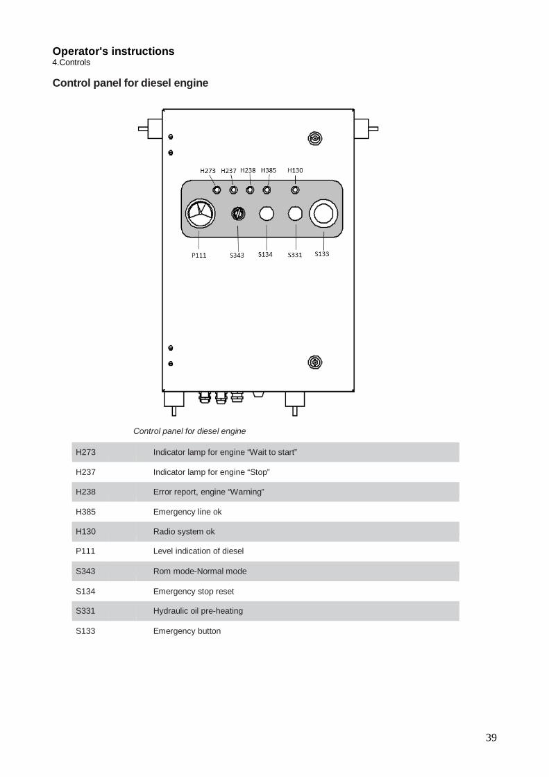
Control panel for diesel engine
H273
Indicator lamp for engine “Wait to start”
H237
Indicator lamp for engine “Stop”
H238
Error report, engine “Warning”
H385
Emergency line ok
H130
Radio system ok
P111
Level indication of diesel
S343
Rom mode-Normal mode
S134
Emergency stop reset
S331
Hydraulic oil pre-heating
S133
Emergency button

40
Operator's instructions 4. Controls
Electric cabinet
A1 electrical cabinet
A Fuses
B
P 110 Test
C
K 200 Relay
D
K 330 Relay
E
K 5 Relay
F
K 132 Safety Module
G
K 11 Main relay
Table 17: Components in electrical cabinet

41
Operator's instructions 4. Controls
Components in electrical cabinet
A S 139 Key
B
S 186 Lights
C
S 486 Steering mode selector
D
A 38 Radio battery charger
E Webasto display
F
S 300 Battery main switch
G Engine check
F
WF Radio transmitter connector

42
Operator's instructions 4. Controls
5. Radio box Safety
Serious Injury Danger of accidental operation
May cause serious personal injury and damage to property
The operator must always have an overview of the drill rig and the remote control box
Always check that the controls are set correctly before operating
Always deactivate the remote control box when it is not in use
The radio box must not be operated from the drill rig when the winch is being used
Serious Injury Danger of accidental operation
When the radio box is deactivated no functions can be controlled
NOTE: Pay attention to the position of the radio box!

43
Operator's instructions 4. Controls
Controls
1 Left hand multifunction lever (Feed positioning) 2 Switch a Positioning b Drilling c Tramming/Positioning
3 Tramming levers left and right a Forward b Neutral c Reverse
4 Multifunction knob. See section Menu views, Navigation
5 Right hand multifunction lever (Boom and feed positioning) 6 Machine stop switch
Stops the diesel engine (must be reset before restart). The range of the machine stop switch is 60 m.
7L/R Jack left/right a Lower front section b Neutral c Raise front section
8/9 N/A 10 Hydraulic Jacks
a Up c Down
11 Winch motor a Wind in b Neutral c Wind out
12 Drill support a Open c Close
13/14/15 N/A 16 Dust collector (DCT) On/Off 17 N/A

44
Operator's instructions 4. Controls
Left-hand multifunction lever
Left-hand multifunction lever Sector Activity
A Feed tilt, front B Feed swing (right) C Feed tilt, rear D Feed swing (left) E Feed extension down F Feed extension up
Table 18: Functions when positioning mode (a) is selected.

45
Operator's instructions 4. Controls
Right-hand multifunction lever
Right-hand multifunction lever Sector Activity
A Feed tilt, front C Boom lift B Boom swing right D Boom swing left J Boom extension in k Boom extension out
Table 19: Functions when positioning mode (a) is selected. Sector Activity
A Rapid feed-forward C Rapid feed-backward B Rotation (Clockwise) D Rotation (Anticlockwise) and Flushing air G Threading H Unthreading I Rotation (Anticlockwise)/Flushing air/Feed-backward E Reduced auto-drilling F Full auto-drilling/collaring
J Low percussion / Flushing air self-holding - lever movement < 0.2 sec
K High percussion / Break loose with deactivated automatic drilling. / Stop flushing air
L Proportional feed pressure./ Proportional rotation Speed. / Only manual percussion
Table 20: Functions when drilling mode (b) is selected NOTE: Move the lever to sector B to stop drilling/rotation

46
Operator's instructions 4. Controls
Sector Activity
J Deactivates drilling (low percussion, rotation and low feed). Does not deactivate flushing air.
K Activates full drilling (high percussion, rotation, flushing air and high feed)
Table 21: Functions during collaring Sector Activity
J Activates collaring (low percussion, rotation, flushing air and low feed)
K Deactivates drilling (percussion, rotation and feed). Does not deactivate flushing air.
Table 22: Functions during full drilling Right-hand multifunction lever-proportional function
Right-hand multifunction lever
Sector Activity X Rotation
K
Feed: Sector L and M have a proportional function for rotation
and feed Move the lever to F via sector D and E for full auto-drilling. Move the lever to F via sector D, E and J for collaring. Move the lever via sector L, M and J for proportional rotation
and feed during collaring. Sector F locks self holding in collaring mode. Set values
for rotation, low feed, low per- cussion are locked

47
Operator's instructions 4. Controls
Touch buttons
Position Function Description
1 Indicates communication Transmitter/Receiver
The symbol flashes during weak communication.
2 Indicates whether the radio box is controlling
The symbol flashes before the remote control box has received the command. The signal lamp illuminates when the radio box has control.
3 Warning Indication, less serious error. Error cause is read in the IFM display
4 Warning / Stop Indication, fatal error. The diesel engine is switched off automatically. Error cause is read in the IFM display
5 Escape Back one step in the menu structure. 6 N/A 7 Differential Lock on/off 8 Flushing air ON / OFF 9 N/A 10 Radio Box ON / OFF The button is held depressed until the display
is switched on. The levers must be in start position when the radio box is started.
11 N/A 12 Switch, Radio box/rig The signal lamp (2) illuminates when the radio
box has control. 13 Start/stop button for the diesel
engine
14 N/A

48
Operator's instructions 4. Controls
15 Signal horn 16 Tramming low / high speed 17 N/A 18 N/A 19 Hydraulic roll-over (option) The feed swing function changes to hydraulic
roll-over if the button is held depressed 20 Winch ON / OFF 21 N/A 22 Reset button for protection of
moving parts Activated on each start or after the cover has been opened.
Menu views Navigation Use the multifunction knob (A) and Escape (B) key to navigate, read or change values in the different menus
Button Description Function A Multifunction knob Navigation knob for navigating in and between the menus.
Enter key confirms settings made and options selected in the menus. The Enter key also works as reset for time-out. See section Time-out function. Settings knob for setting de- sired values.
B Escape Goes back one step in the menu structure. Any changes that have been made in a menu will not be confirmed unless Enter is pressed first.

49
Operator's instructions 4. Controls Menu description Menus for information/adjusting
The menus show current information or provide the option for setting adjustable values. Winch
force and tramming speed are also regulated in the menus.
Drilling
This menu shows the current values for drilling.
Upper box shows:
Feed pressure
Engine RPM
Lower box shows:
Rotation
Percussion
Menu for hole depth/hole length
Boreholes The upper box shows current hole length/hole depth, drill bit position and penetration rate.
Resetting with the touch button resets all values (bit on the stone then push button 14 on
the RRC)
Enter desired hole depth in the lower box, with the button 4.

50
Operator's instructions 4. Controls
Activation of hole depth/hole length setting
1. In drilling mode turn the multifunction knob (4) then double click it. Turn the knob
to select between hole depth or hole length.
2. Click the multifunction knob once more to activate the length setting. Turn the knob
to set the correct length.
3. Click one last time on the multifunction knob to save the value.
Note: make sure to follow step by step the sequence on how to change the rod or the deep recorder will not identify the second one Menu tramming speed, winch power and feed pressure
Tramming speed
Tramming speed The menu for tramming speed adjustment appears when the switch is in the Tramming position, with tramming levers
activated. Adjust tramming speed using the multifunction knob.

51
Operator's instructions 4. Controls
Winch force
Winch force The menu for winch force adjustment appears when the switch is in the Tramming po- sition, with the touch button for Winch activated. Adjust winch force using the multi- function knob.
Feed pressure
Feed pressure When feed forward is activated, feed pressure can be adjusted using the multifunction knob. The screen is visible during the change. The functionality must have been activ- ated earlier in Settings (RRCFP). Menus for testing The menus for testing are shown below. n The menus for testing are accessed by holding the Watermist button and the On button depressed when the radio box is started. n Navigate between the test menus using the switch.
Testing the levers
Each lever movement is shown with the interval 0 - 100.

52
Operator's instructions 4. Controls
Testing the tramming levers
Each lever movement is shown with the interval 0 - 100. Testing the circuit breakers
Testing the circuit breakers
The white indication in the centre of the symbol moves up/down when testing circuit
breakers, and indicates correct function.
Testing the touch panel, multifunction knob and tilt sensor
Touch buttons in the menu illuminate during testing, and indicate correct function.
The multifunction knob is shown with positive and negative values.
The tilt sensor detects the position of the radio box.
o Permitted inclination is shown with 0.
o Unpermitted inclination is shown with 1.
53
Operator's instructions 4. Controls Error messages Error messages are shown below.
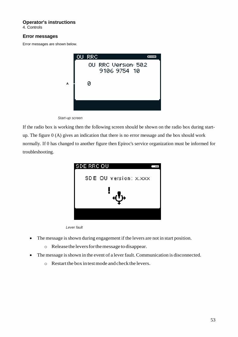
Start-up screen
If the radio box is working then the following screen should be shown on the radio box during start-
up. The figure 0 (A) gives an indication that there is no error message and the box should work
normally. If 0 has changed to another figure then Epiroc's service organization must be informed for
troubleshooting.
Lever fault
The message is shown during engagement if the levers are not in start position.
o Release the levers for the message to disappear.
The message is shown in the event of a lever fault. Communication is disconnected.
o Restart the box in test mode and check the levers.

54
Operator's instructions 4. Controls
Low battery
The message is shown in the event of low battery level.
o Replace the battery.
Communication fault
The message is shown when radio communication is interrupted.
o Approach the rig for automatic reconnection. NOTE: The blue signal lamp on the box flashes when communication is weak.
Button fault

55
Operator's instructions 4. Controls
The message is shown if the wrong button/button combination is held depressed when
the box is started.
o Restart the radio box.
The message is shown in the event of a fault in the button.
o Go to test mode to check the buttons.
Inclination error
The message is shown in the event of unpermitted inclination of the radio box. The box
loses control and shuts down the current function.
o Set the radio box correctly. The message disappears and control of the radio box
is restored.
Internal fault
The message is shown in the event of a fault in the radio box.
o If the error message remains after restart, contact the Epiroc service or-
ganisation.
The message is also shown if the switch (touch button 12) has to be depressed to take
control with the radio box.

56
Operator's instructions 4. Controls
Function Time-out function The radio box has a time-out function. When the box has not been activated for 10 seconds the
levers are inactive. Reset with the horn button, Enter key or by changing mode with the switch.
Start-up The switch on the radio box must be in the Tramming/positioning position in order to en- able start-up of the radio box.
1. Start the radio box by holding button (E) depressed until text is visible on the display.
NOTE: The levers must be in start position when the radio box is started.
2. Transfer control to the radio box by pressing button (D).
NOTE: The screen is shown and the signal lamp (B) flashes before the radio box has taken control. The signal lamp (B) illuminates when the radio box has taken control.
3. Start the engine by pressing button (C). The signal lamp (B) should illuminate.

57
Operator's instructions 4. Controls Stops The system is switched off as follows.
1. Switch off the diesel engine with button (C).
2. Switch off the radio box with button (E)
3. Switch off the CAN system with the key.
Drilling For information about drilling, see the operator's instructions.
Stop drilling/rotation
The following functions for stopping drilling/rotation are unique to the radio box.
Stop drilling/rotation function
Move the right-hand multifunction lever to sector (B) to stop drilling/rotation.
Stop drilling/rotation function in adjustment mode
In the event of repositioning during ongoing drilling (adjustment) the levers are inactive after 5
seconds, except the stop drilling/rotation function. It operates after 5 seconds.

58
Operator's instructions 4. Controls
Display heater
Display heater in operation If the temperature falls below approximately -9 °C, the display heater is switched on automatically.
The symbol (A) is shown in the display. The heater is also switched off automat- ically around
approximately 0 °C.
If the battery starts to become discharged and the battery warning is shown, the heater is switched
off despite the temperature needing the heater. This is to avoid affecting the use of the radio box.
The battery time will decrease when the heater is running. How much de- pends on how cold the
temperature is and how long the heater is running.
If the radio box has a heater, the symbols for OFF/ON appear as follows:
Display heater off Display heater on No display heater

59
Operator's instructions 4. Controls Replacing the box Use the learn link routine for replacing the radio box.
Learn link connects transmitter (radio box) with receiver (rig). After the procedure, the rig
addresses to the new radio box.
Learn-link 1. Switch off the rig with the main power contactor (S300) and switch off the radio box.
Connect in accordance with the figure below. Connect the radio box via Learn-link cable (9106
9715 24) to KC21 on the A1-cabinet.
2. Activate the main power contactor (S300) to the ON position (I).
3. Start the radio box in learn-link mode by depressing buttons (5) and (10) simultan- eously
until the "Start learn-link" image is shown on the display.
Start the radio box in learn-link mode

60
Operator's instructions 4. Controls
Start learn link
4. Press Enter to start learn link. Now the transfer of data starts. The transfer is complete when the following image is shown on the display:
Transfer complete
6. Switch off the radio box with the emergency stop.
7. Switch off the rig's control system.
8. Reset the rig by disconnecting the Learn-link cable and the rig is ready to be restarted.

61
Operator's instructions 5. Operating
6. Operating
Activating the remote control box
Serious injury Danger of accidental operation May cause serious personal injury and damage to
property The operator must always have an overview of the
drill rig and the remote control box Always check that the controls are correctly
adjusted before operating Always deactivate the remote control box when not
in use
NOTE: Monitor pressure gauges and display for diesel engine when in operation. NOTE: Always have the drill rig and the remote control box under surveillance.
NOTE: If the remote control box is turned off once the system has been activated, the diesel engine will stop and
deactivate the whole drill rig.
1. Activate the drill rig's main power contactor. Switch (S300) in position (1a).
Main power contactor S300

62
Operator's instructions 5. Operating
2. Turn the ignition lock S139 on the diesel panel to position (I).
Control panel for diesel engine
3. The emergency stop is always activated when the drill rig has been switched off. Reset the emergency stop cable with reset button (S134).

63
Operator's instructions 5. Operating
4. Activate the circuit breaker on the remote control box by holding touch button (10) de- pressed for several seconds. The display and all indicator lamps illuminate for a short time. Indicator lamp (1) maintains its constant glow and indicator lamp (2) starts to flash.
Touch buttons
5. Press touch button (12). Indicator lamp (2) stops flashing and has a constant glow, and the
box is activated.

64
Operator's instructions 5. Operating
Diesel engine starting NOTE: Monitor pressure gauges and display for diesel engine when in operation.
1. Check that the ignition switch S139 (ignition key) is in position (I). Wait until diesel engine
preheating is finished and indicator lamp H273 has extinguished.
2. Start the engine with touch button (13).
Touch buttons
NOTE: NOTICE! If the engine does not start, stop the starting procedure after 5 seconds.
NOTE: If a fault is indicated by the indicator lamps on the radio box or the diesel panel for the diesel engine: switch off the engine and check to see which symbol(s) is/are illuminated and then rectify the fault.
When the engine is warm, with the knob 4 in tramming mode and pushing the button S331
on the electrical box you will activate the automatic pre-heating until the hydraulic oil will
reach 35°C. You can deactivate it by turning the knob in positioning or drilling mode.

65
Operator's instructions 5. Operating
Stopping the diesel engine
NOTE: If the engine is hot, run it at idling speed for a couple of minutes before switching off.
1. Switch over the remote control box to tramming mode. Switch (2), position c.
NOTE: NOTICE! The engine speed must be lowered to idling before the compressor is discharged.
Remote control box
2. Stop the diesel engine by depressing touch button (12) or (13).
3. Switch off the box by pressing and holding touch button (10).
4. Deactivate the drill rig's main power contactor. Switch S300 in position (1b).

66
Operator's instructions 5. Operating
Drill rig main power contactor
Feed Rotation
General
Feed rotation can be carried out both manually and hydraulically. Hydraulic feed rotation is an
option
Upward and horizontal drilling Upward and horizontal drilling requires higher feed force in order to compensate for the weight of
the rock drill and drill cradle. The drill feed pressure needs to be increased by approx. 30-40 bar
during upward drilling.
NOTE: Exercise caution regarding the drill rig's stability. Note that the rig's stability is affected by
forces from boom movements and/or forces from the boom feed. See chapter Technical Data.

67
Operator's instructions 5. Operating
Maintenance for drilling upwards
The following maintenance is added for drilling upwards:
Grease nipples at sprocket wheels require daily filling with grease. See Maintenance schedules.
Slide rails require daily cleaning. See Maintenance schedules.

68
Operator's instructions 5. Operating
Hydraulic feed rotation
Safety
Operation
NOTE: Pay attention to how the hoses move during rotation in order to prevent them from being trapped or damaged in some other way.
1. Position the feeder so that it is in such a position that the hydraulic feed rotation can rotate
freely without damaging the feeder or other parts, see figure.
2. Press and hold touch button (19) and, at the same time, move the left-hand multifunction
lever (1) to the left or right for the desired position, see illustration.
Risk of injury Moving parts Risk of personal injury The feeder must be in horizontal position during
rotation. Deactivate the remote control box during rotation in
order to avoid the risk of accidental operation.

69
Operator's instructions 5. Operating
Tramming Operation
Serious injury Danger of accidental operation
May cause serious personal injury and damage to property
Always check the prevailing ground conditions where the rig shall be operated
Inclination angles for Downward/Upward/Lateral CANNOT be combined with each other
Do not exceed the inclination angles, See technical data
Note the gradient meters' values
Never operate the drill rig from the down side during remote control operation
Always ensure that unauthorized personnel are outside the working area
The operator must always have an overview of the drill rig and the remote control box
Always check that the controls are correctly adjusted before operating
Always deactivate the remote control box when it is not in use.
May cause serious personal injury and damage to property
Keep away from high-voltage cables
Feeder and boom must be in transport position before the jacks are raised.
For slope higher than 5° must use turtle
Risk of injury Note that worn tires reduce friction with the ground considerably
and consequently increase the risk of sliding

70
Operator's instructions 5. Operating
Position for tramming (tramming position)
NOTE: The gradient meter shows the chassis frame inclination and not the actual ground inclination 1. Set the remote control box in tramming and positioning mode. Switch (2), position (c).
2. Position the feeder to tramming position. Multifunction levers (1) and (5).
3. Raise the hydraulic jacks. Switch (10) in position (a) for the rear jacks, and switch (7) in
position (c) for the front jacks.
4. Select tramming speed depending on terrain characteristics, touch button (16). Turn the
multifunction knob (4) for fine adjustment of tramming speed. The display shows the
current speed as % of a maximum speed of 100%, in case you can activate the differential
lock, touch button (7).

71
Operator's instructions 5. Operating
Touch buttons
NOTE: Low tramming speed gives the highest traction and vice versa.
5. Operate the tramming levers (3) to move the drill rig in the desired direction.
NOTE: If one wheel pair is operated while the other is stationary then the tyres are subjected to
unnecessary stresses. This should therefore be avoided.
Checking after tramming All emergency stop wires and all emergency stops must be checked after tramming.
Tramming - General principles
Tramming, general
Position the boom and feed beam to transport position. Always check the terrain where the drill rig shall be operated. Adapt speed according to terrain.
Left: Correct position for general tramming. Right: Wrong position.

72
Operator's instructions 5. Operating
Maximum permitted inclination angles during setting- up for drilling
Setting-up for drilling with the feeder in vertical position and centered between the wheels
Setting-up for drilling with the feeder in vertical position and swung max to left

73
Operator's instructions 5. Operating
Setting-up for drilling with the feeder in vertical position and swung max to right
NOTE: The rig is symmetrical so the same angles apply as in the chapter "Setting-up for drilling with the feeder in vertical position and swung max to left".
Setting-up for drilling with the feeder top in extreme position forwards, the feeder laterally vertical and centred between the wheels
Setting-up for drilling with the feeder top in extreme position rearwards, the feeder laterally vertical and centered between the wheels

74
Operator's instructions 5. Operating
Using the winch when tramming
Serious injury
Risk from dumping and moving parts
May cause serious personal injury and damage to property
Ensure that unauthorized personnel are outside of the working area
Never use the winch with less than three turns remaining on the winch drum
Risk from dumping and cable failure
May cause serious personal injury and damage to property
The anchorage point must be firm and secure (pay attention to local regulations)
The safety hook must not be able to slide or detach from its attachment point
A damaged cable or hook must not be used. See the section, Wire ropes, in the maintenance instructions.
Check that the winch locking mechanism is fully engaged in the drum before use, following the attachment of the cable eye on the anchorage point
May cause serious personal injury and damage to property
The operator must always have an overview of the drill rig and the remote control box
Always check that the controls are correctly adjusted before operating
Always deactivate the remote control box when not in use
The remote control box must not be operated from the drill rig when the winch is being used

75
Operator's instructions 5. Operating
General The winch can be used as an additional safety feature, either to provide extra tractive force when tramming up or down a slippery slope or as an extra brake when tramming down an incline. NOTE: The winch should not be used for any other purpose.
NOTE: The winch can only be operated from the remote control box. Remember that the max. pull force is of 3600Kg.
Action before winching
The cable and eye must always be inspected before use. The rig must be switched off during anchoring or adjustment of the cable. A damaged cable must always be replaced.
Checking the attachment of the winch cable It is of the utmost importance that the cable is correctly fitted in the winch eye. It must be checked:
before each use
when replacing the cable
when first attaching the cable after shortening

76
Correct assembly
Correct assembly
A Cable B Rope lock C Connector sleeve with wedge plug D Hook

77
Operator's instructions 5. Operating
1. The cable must run in line with the eye on the connector sleeve.
2. The rope lock must only lock the end cable.
3. The free end must be at least 6-9 x the diameter of the cable in order to ensure that the
whole section of the cable that is either lashed-in or annealed and tapered is out- side
the connector sleeve.
Tramming uphill
Serious injury
Risk from dumping and moving parts
May cause serious personal injury and damage to property
The angles for Downward/Upward/Lateral CANNOT be combined with each other
Do not exceed the inclination angles, See technical data
Note the gradient meters' values
Never operate the drill rig from the down side
Keep the winch cable continuously taught
1. Activate the remote control box (see chapter: Activating the remote control box).
2. Check that the remote control box is in tramming mode. Switch (2), position c.
3. Disengage the winch drum with the disengagement mechanism (A) to enable the cable
to be pulled out.
Disengagement mechanism, winch

78
Operator's instructions 5. Operating
4. Pull out the wire and fasten the eye to the anchor point.
5. Lock the winch drum with the disengagement mechanism (A).
6. Set the winch potentiometer to the desired pressure, touch button (20). Turn the multi-
function knob (4) to change the winch pressure. The display shows the current pres-
sure as % of a maximum pressure of 100%. Depress the multifunction knob (4) at the
same time as turning it to change tramming speed.
Control panel for diesel engine
7. Activate the winch circuit. Touch button (20).
8. Activate wind-in manually to ensure the lock mechanism is fully engaged in the drum
before loading the winch. Switch (11).
Control panel for diesel engine

79
Operator's instructions 5. Operating
NOTE: Do not commence tramming without ensuring that the winch locking mechanism
is fully engaged (A).
The winch locking mechanism is fully engaged (A).
9. Reverse up the incline using the tramming levers. Make sure that the wire is kept taut
constantly.
Tramming downhill
10. Fasten the eyelet to the anchorage point.
11. Set the winch thrust using the multifunction knob (4). Turn it clockwise to reach max-
imum pressure 100%.
12. Reduce the winch cable pressure gradually until the drill rig can be driven smoothly
down the incline with a suitable counterbalance from the winch. Make sure that the
cable remains taut constantly. NOTE: The winch will work (inwards) simultaneously while the tramming levers are activated

80
Operator's instructions 6. Before drilling
7. Before drilling
Safety
May cause severe personal injury Ensure that unauthorised personnel are
not within the working area Follow the instructions carefully
Setting up for drilling
Risk of tipping May cause severe personal injury and
damage to property The angles for Downward/Upward/Lateral,
specified in Technical data, must NOT be combined
Do not exceed the tilt angles, see Technical data
Note the gradient meters' values Never operate the drill rig from the
downhill side Ensure that unauthorised personnel are
not within the working area
Risk of feed beam bending To avoid overloading the feeder, do no
use the cylinder alone for lowering the boom, or the cylinder for feed extension individually to place the feeder against the ground

81
Operator's instructions 6. Before drilling
1. Set the remote control box in tramming and positioning mode. Switch (2), position
(c).
Remote control box
2. Set up the rig horizontally using the jacks. Switch (10) in position (c) and switch (7) in position (a).
Correct set up for drilling
3. Set the remote control box in drilling mode. Switch (2), position (b).
4. Position the feed beam and boom to the desired position. Set the feed spike firmly against the ground without lifting the drill rig. Right and left-hand multifunction lever.
NOTE: Do not lift the drill rig with the feeder!

82
Operator's instructions 6. Before drilling
Setup for drilling - General principles General setup Align the rig as horizontally as possible using the jacks. Place the feed spike firmly against the ground without lifting the frame off the ground.
NOTE: Position the boom and feeder with smooth movements.
Uphill setup
Left: Correct position for drilling uphill. Right: Wrong position.
Downhill setup NOTE: Notice! If the inclination is >10° then the winch should be used!
Set up the drill rig as close to the horizontal as possible.
Left: Correct position for drilling downhill Right: Wrong position.
83
Operator's instructions 6. Before drilling
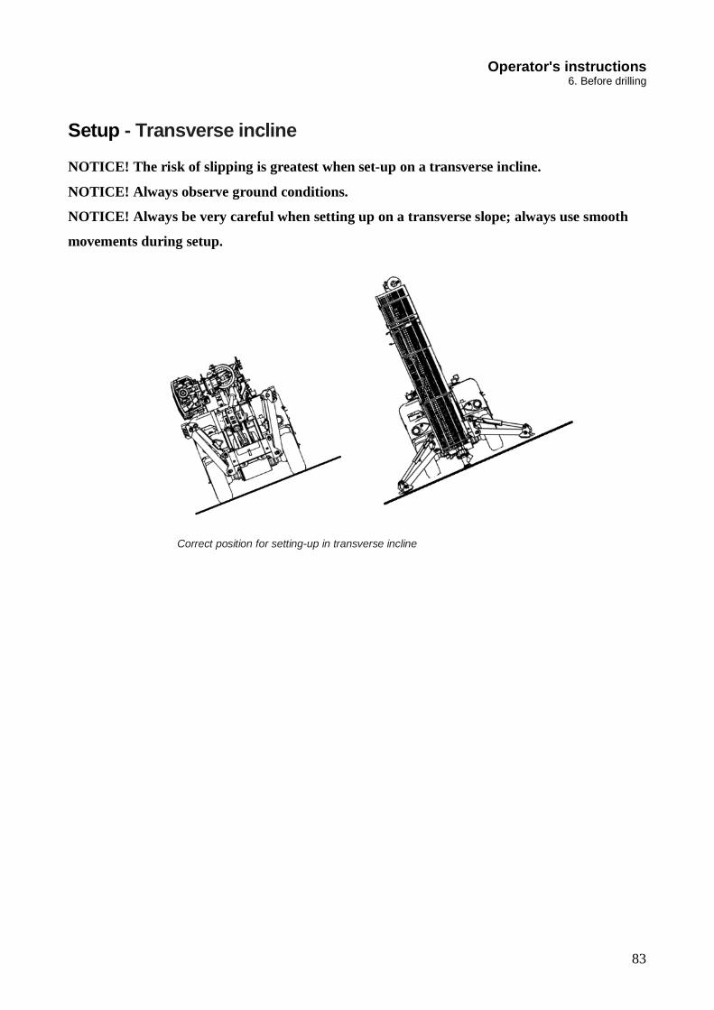
Setup - Transverse incline
NOTICE! The risk of slipping is greatest when set-up on a transverse incline.
NOTICE! Always observe ground conditions.
NOTICE! Always be very careful when setting up on a transverse slope; always use smooth
movements during setup.
Correct position for setting-up in transverse incline

84
Operator's instructions 7. Drilling
8. Drilling
Danger of accidental operation May cause serious personal injury and
damage to property The operator must always have an
overview of the rig and the remote control box
Always check that the controls are correctly adjusted before operating
Always deactivate the remote control box when it is not in use
Start of manual drilling
1. Set the remote control box in drilling mode, switch (2), position b.
Remote control box
2. Check that the dust collector and flushing air are activated. When the dust collector is
active, the symbol for the dust collector is shown in the display on the radio box (A).

85
Operator's instructions 7. Drilling
Menu screen radio box
3. Close the drill-steel support. Switch (12).
4. Lower the rock drill until the drill bit is pressing lightly against the ground. Right
multi- function lever (5), position (c).
5. Start rotation/flushing air. Right-hand multifunction lever to left (sector d). (1 second
for self-holding). Check that flushing air is activated. The symbol for flushing air is
then shown in the display on the radio box (B). If no symbol is visible in the display,
press button (16).
Sector description, right-hand multifunction lever

86
Operator's instructions 7. Drilling
Menu screen Radio box
6. Start drill feed. Right-hand multifunction lever forwards through sectors a and f.
7. Low percussion is activated through turning right-hand multifunction lever (anticlock- wise): NOTE: Use the drill lever intermittently through sectors a and f until solid rock is reached.
NOTE: Collaring with feed too high will make the drill bit veer off in the wrong direction and result in a deviating hole and bent drill string.
8. Drilling can be suspended by moving the right-hand multifunction lever through sec- tors a and f to the end position. The lever can be released back to neutral once the self-holding circuit has started. After a few seconds the percussion switches from automatic to high.
9. Turn the drill lever (clockwise) to activate high percussion pressure.
10. Turn the right-hand multifunction lever to the right to stop all drilling functions (rota- tion, feed, percussion and flushing air).
11. To stop drilling but maintain flushing air:
a. In Low impact turn the right-hand multifunction lever clockwise.
b. In high impact turn the right-hand multifunction lever clockwise
Feeder adjustment during drilling
The equipment can be damaged The drill rig can only be interrupted in
drilling mode or with emergency stop
The feeder can be readjusted as necessary by operating the left-hand multifunction lever (1).

87
Operator's instructions 7. Drilling
Checks during drilling
Monitor drilling performance and pay particular attention to the points below: Should anything out of the ordinary occur, stop drilling and clear up the trouble or ask service personnel to investigate. 1. Rock drill :
• Abnormal percussion hose vibration. - Check the pressure in the rock drill accumulators.
• Check that the shank adapter is sufficiently lubricated. - Lubricating oil/air should leak out at the shank adapter.
• Abnormal leakage from the rock drill. • Note that the shank adapter has a "float position", i.e. it is pressed out about 4-
6 mm from the sub frame. Break loose Break loose (applies to extension drilling)
Sector description, right-hand multifunction lever
Danger of accidental operation May cause serious personal injury and
damage to property The operator must always control of the
rig and the remote control box Always check that the controls are
correctly adjusted before operating Always deactivate the remote control box
when it is not in use

88
Operator's instructions 7. Drilling
1. Stop drilling by turning the right-hand multifunction lever (5) clockwise/anticlockwise, or move the right-hand multifunction lever to the right, sector (b), for total shut off.
2. Turn the right-hand multifunction lever clockwise to activate high percussion. Release the lever when the joint is loose.
NOTE: Release/rattling pressure is used during break loose. The break loose pressure is retrieved from the operator panel.
Rod adding
Danger of accidental operation May cause serious personal injury and
damage to property The operator must always control of the
rig and the remote control box Always check that the controls are
correctly adjusted before operating Always deactivate the remote control box
when it is not in use The rock drill must never be moving when
adding rods.
1. Lock the coupling sleeve, close the drill-steel support and keep it close.
2. Disconnect the rock drill by setting the right-hand multifunction lever to the unthread- ing position (H).

89
Operator's instructions 7. Drilling
3. Set the lever for drill feed in neutral position.
4. Move the rock drill up by pulling the right-hand multifunction lever backward (C).
5. Open the guard and position the drill steel in drill center.
6. Move the rock drill's tool shank down towards the drill steel.
NOTE: When the guard is open, only reduced feed can be obtained.
7. Close the guard for moving parts and press the reset button on the radio box (23).
8. Thread together the rock drill's tool shank with the drill steel.

90
Operator's instructions 7. Drilling
Threading
1. Make sure the shank joints are broken loose.
Remote control box
2. Open the drill-steel support. Switch (12) position (c).
3. Pull up the drill string up until the sleeve reaches the drill-steel support. Right-hand multifunction lever (5), sector (c).
4. Close the drill-steel support. Switch 12 to position (a).
5. Activate unthreading by moving the right-hand multifunction lever to sector (g).
Danger of accidental operation May cause serious personal injury and
damage to property The operator must always control of the
rig and the remote control box Always check that the controls are
correctly adjusted before operating Always deactivate the remote control box
when it is not in use
91
Operator's instructions 7. Drilling
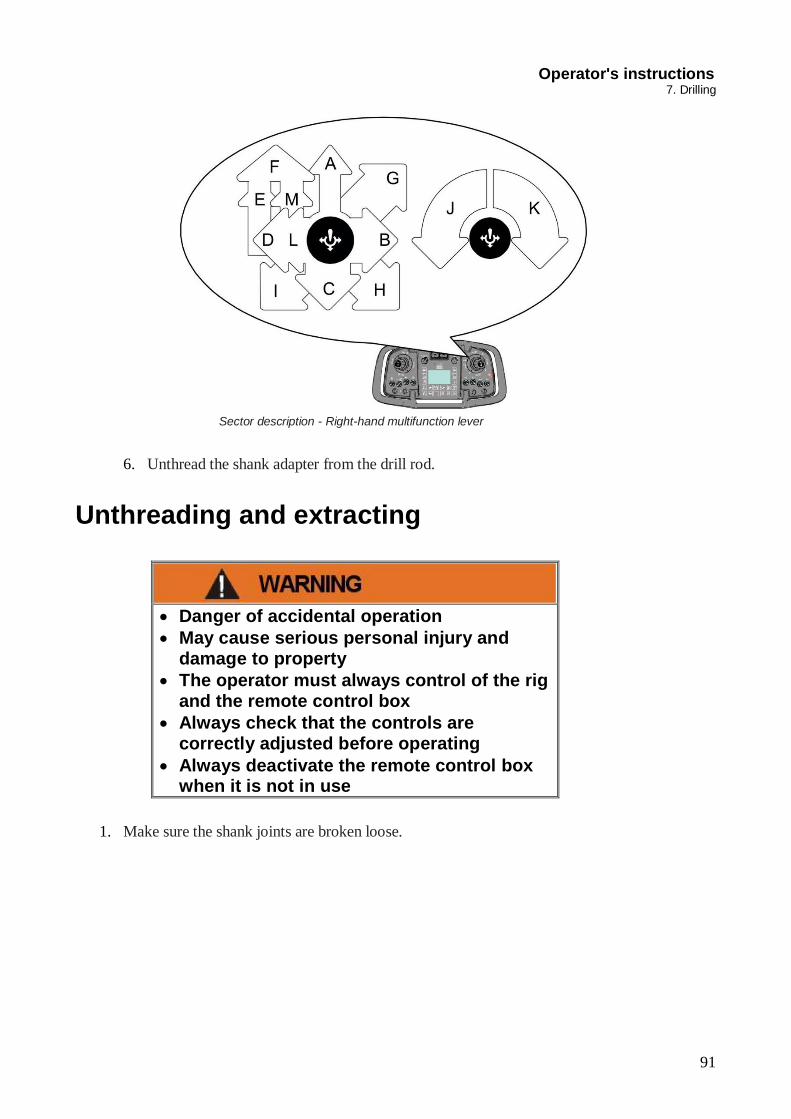
Sector description - Right-hand multifunction lever
6. Unthread the shank adapter from the drill rod.
Unthreading and extracting
Danger of accidental operation May cause serious personal injury and
damage to property The operator must always control of the rig
and the remote control box Always check that the controls are
correctly adjusted before operating Always deactivate the remote control box
when it is not in use
1. Make sure the shank joints are broken loose.

92
Operator's instructions 7. Drilling
Remote control box
2. Open the drill-steel support. Switch (12) position (c).
3. Pull up the drill string up until the sleeve reaches the drill-steel support. Right-hand multifunction lever (5), sector (c).
4. Close the drill-steel support. Switch 12 to position (a).
5. Activate unthreading by moving the right-hand multifunction lever to sector (h).
Sector description - Right-hand multifunction lever
6. Unthread the shank adapter from the drill rod.

93
Operator's instructions 7. Drilling
Changing drill bit
Moving parts Risk of personal injury, clothing can be
trapped Stop rock drill rotation when changing
bits
NOTE: Never start percussion with the drill bit free without any resistance
1. Operate the feeder until the spike is approx. 10 cm from the rock.
2. Make sure that the rotation lever is in neutral
3. Move the drill bit forward until it is pressed against the rock.
4. Turn the right-hand multifunction lever (5) to the right to activate break loose.
5. Switch off percussion pressure when the drill bit has loosened. If the percussion pressure is engaged for too long then the drill steel can detach from the shank adapter.
6. Unscrew the old drill bit by hand and replace with a new one.
Action in case of drilling problems
Drilling problems
If the following trouble occurs during drilling:
• Hot coupling sleeves (loose coupling sleeves) • Difficulties in uncoupling the coupling sleeves • Hole deflections

94
Operator's instructions 7. Drilling
High coupling sleeve temperature
NOTE: The coupling sleeve temperature should not exceed 120ºC (248ºF) 1. Excessive coupling sleeve temperature is indicated by:
a. Measuring with a thermometer b. Oil dripping from the rock drill vaporises on the coupling sleeve c. The coupling sleeve changes colour
2. Depending on the layers of the rock, temperature can vary even within a small area. High coupling sleeve temperature is usually due to a poor relationship between drill feed pressure, percussion pressure and rotation pressure. The follow- ing solutions are recommended to reduce coupling sleeve temperature. a. Check the condition of the drill bit. An over drilled bit gives less torque in the
coupling sleeve. Grind the drill bit.
b. Change to a drill bit with ballistic buttons. c. If the rock is too hard for ballistic bits, then...
reduce rotation speed as much as possible without causing the drill string to rotate jerkily check the drill feed pressure and set it to the recommended value Reduce percussion pressure to below the basic setting (5-10 bar). A reasonable reduction in penetration rate must be accepted.
Difficulties in loosening the coupling sleeve The best method of loosening the coupling sleeve is to "drill" the last few centimetres without feed pressure and rotation, leaving percussion active for a few seconds to break loose the coupling sleeve.
Hole deflection 1. Try to drill with as low a drill feed pressure as possible 2. Check the condition of the drill bit 3. Drill the first drill steel with reduced drilling for at least half of the drill steel in
order to minimise hole deflection at the start of the hole.

95
Operator's instructions 8. Options
8. Options
Electric filler pump
Figure: Electric filler pump
The pump is used to fill fuel. 1. Make sure that the hose and the filter are clean. 2. Connect the attached hose to the fuel source. 3. Press START on the control panel (B). The top-off electro pump stops automatically when the fuel tank of the drilling carriage is full, or press STOP (A) to interrupt dispensing.

96
Operator's instructions 8. Options
Water flush / Water mist Water flushing
Water flush pump
The pump is used to perform a water flushing.
1. Connect the input hose to the fitting A.
2. Turn the valve B in order to activate the water pump
3. Make sure that the DCT is activate from the Radio box (button 16).
4. Activate the water flushing button no 6 on the touch panel and switch of the air
(button no 8 on the touch panel). Operator's instructions

97
8. Options
NOTE: you can adjust the water flow from the regulator A show in the picture and the water pressure from the regulator B .
NOTE: In case of cold temperature, it is recommended to drain the water system by
opening all the valves A in the picture below and activating flushing with air.
NOTE: In case the water pressure is connected in input, A it is already too high and you
don’t need the pump, you can switch off it from the button 16 on the radio box. Operator's instructions
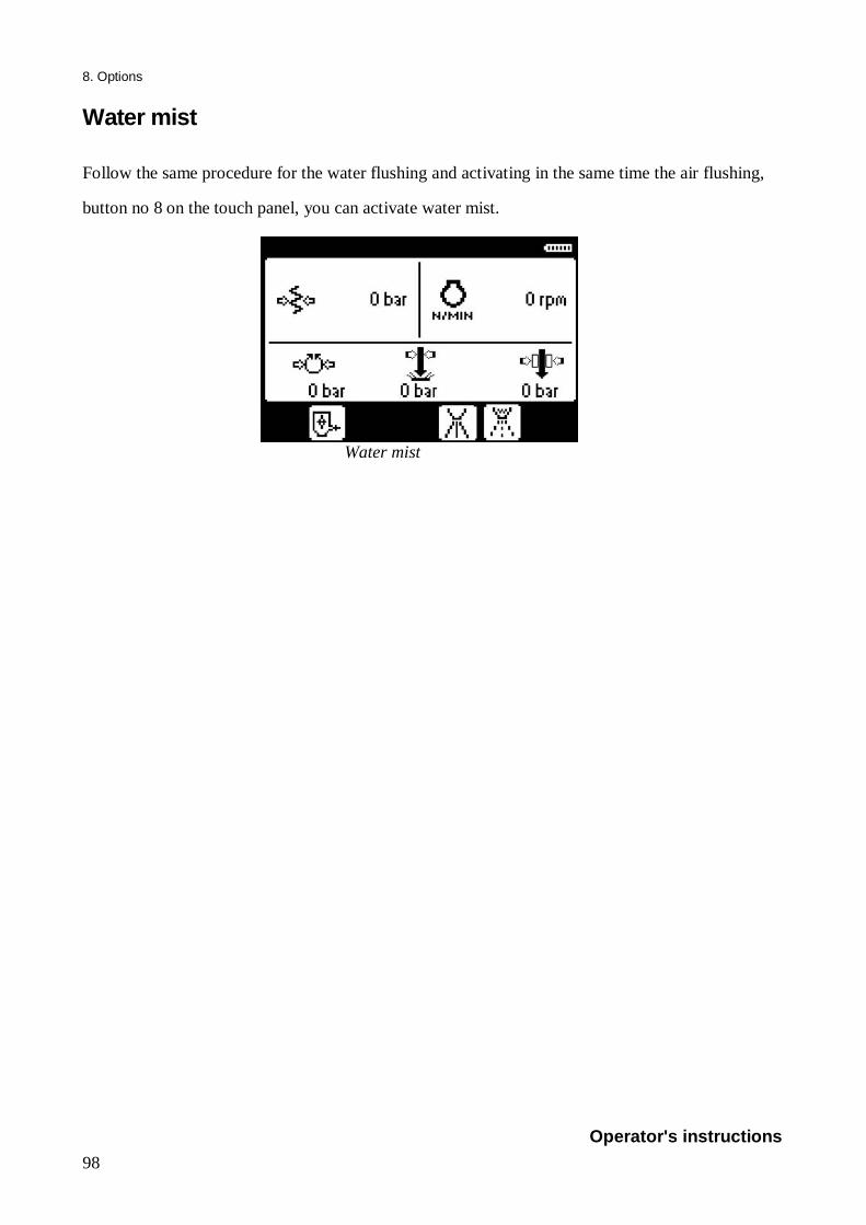
98
8. Options Water mist
Follow the same procedure for the water flushing and activating in the same time the air flushing,
button no 8 on the touch panel, you can activate water mist.
Water mist
Operator's instructions

99
8. Options
Auxiliary hydraulic fittings
Figure: Auxiliary hydraulic fittings
The auxiliary hydraulic fittings provide hydraulic power to the machine's auxiliary
applications (hydraulic sharpener, etc.)
1. Connect the equipment's output and return to the quick connectors (C).
2. Press button B from the control panel to power the auxiliary application.
3. To interrupt hydraulic power to the application, press button A.
Before disconnecting the auxiliary
application from the machine, make sure the auxiliary system is not powered (indicator light D off)
Protect your eyes from contact with
hydraulic oil. Wear protective goggles.
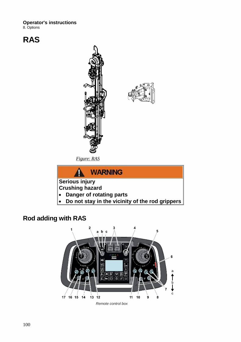
100
Operator's instructions 8. Options
RAS
Figure: RAS
Rod adding with RAS
Remote control box
Serious injury Crushing hazard Danger of rotating parts Do not stay in the vicinity of the rod grippers

101
Operator's instructions 8. Options
1. Lock the coupling sleeve; close the drill-steel support, and keep it close
2. Move the right-hand multifunction lever (5) into threading position (H) in order to
dis- connect the rock drill from the drill steel.
3. Move the right-hand multifunction lever (5) into position (C) in order to move the
rock drill back.
4. Left-hand multifunction lever (1) in position (C) in order to move the drill steel into
drill centre.
5. Left-hand multifunction lever (1) to sector (C) in order to obtain hard grip.
6. Right-hand multifunction lever (5) to sector (G) in order to thread the drill steel into
the rock drill.
7. Left-hand multifunction lever (1) to neutral position in order to obtain loose grip.
8. Right-hand multifunction lever (5) to sector (G) (threading) until both joints are
tightened.
9. Right-hand multifunction lever (5) to sector (E) in order to open the claws.
10. Left-hand multifunction lever (1) to sector (A) in order to move back the rod
handling arms.
11. Open the drill supports with circuit breakers (12) and (13).

102
Operator's instructions 8. Options
Unthreading and extracting with RAS Knock loose the joints before extraction:
1. Open the drill-steel support fully by moving the drill-steel support selector to
opening position.
2. Pull up the drill string until the sleeve is in the drill-steel support by holding the
rapid feed selector in UP position.
3. Swing the rod handling arms to drill centre by moving the rod handling lever to the
arm to centre position.
4. Grip the drill steel by moving the lever for rod handling to closing position.
5. Tighten the joint between the shank adapter and the upper rod slightly by holding
the rotation/feed lever at drill rotation position for a few brief intervals.
6. Close the drill-steel support by moving the drill-steel support selector to closing
position.
7. Apply loose grip by moving the lever for the rod handling arms to NEUTRAL
position and the rod gripper lever to loose grip position.
8. Unscrew the drill steel fully from the sleeve in the drill-steel support by holding the
rotation/feed lever in reverse rotation position.
9. Raise the rock drill about 10cm by holding the rapid feed lever in UP position.
10. Apply hard grip by moving the rod gripper lever to CLOSED.
11. Unscrew the shank adapter from the upper coupling sleeve by holding the rotation
lever in reverse rotation position.
12. Unscrew the shank adapter fully from the drill steel. Hold the rotation lever in
reverse rotation position. Move the lever back to NEUTRAL once the shank adapter
has been unthreaded.
13. Move the drill rod away from drill centre by moving the lever for the rod handling
arms to the from drill centre position.
14. Lower the rock drill by holding the rapid feed lever in the DOWN position and then
thread the shank adapter into the coupling sleeve that is fastened in the drill-steel
support by holding the rotation lever in drill rotation position.

103
Operator's instructions 8. Options
Filter with Pre-Cat The filter with Pre-Cat system is constructed using silicon carbide (SiC) filters with oxidation
catalysts, positioned in front to guarantee the reduction of the unburned hydrocarbon (HC) and carbon
monoxide (CO) emissions.
This combination allows the nitrogen dioxide (NO2) level to be raised which, unlike oxygen (O2),
allows combustion of the particulate at compatible temperatures with those of the exhaust gases.
The silicon carbide particulate filter does not require frequent maintenance. Cleaning is required and
consists of cooking the filter and pulsing air through it to remove ash.
This cleaning is normally carried out every 1200 operating hours, or whenever the electronic control
unit indicates, cleaning is required.
The oxidation catalyst must be cleaned every 3000 hours of use by washing in warm water and a
neutral detergent.
The system can be applied to all diesel engines, without limitations in terms of engine age.
The operation of the filter is only guaranteed with the use of diesel that meets the EN590
legislation.

104
Operator's instructions 8. Options Use and maintenance The installation of a BPF R620 system does not change the use and the maintenance of the engine.
The maintenance intervals indicated by the vehicle/engine manufacturer for the other systems do not
change and must be strictly respected.
For the functioning of the BPF R620 systems is mandatory to take care of the indications of the status
LED. The following indications must be strictly observed:
System status The status LED shows with its signaling the status
of the system when the engine is running. The
indications of the LED and their meanings are
showed in the following:
FIXED GREEN: normal operation.
FIXED RED: high pressure alarm.
BLINKING RED: low pressure alarm.
BLINKING RED/GREEN: high pressure alarm
and low pressure alarm acknowledged.
DOUBLE BLINKING RED: pressure warning
TRIPLE BLINKING RED: warning inlet temperature, warning outlet temperature, warning
additional temperature, warning additive pump, warning aided regeneration device (glow plugs),
warning plausibility checks, warning additional pressure (if no other signal is active).
QUADRUPLE BLINKING RED: closed additional relay.
QUINTUPLE BLINKING RED: ALARM MEMORY full.
DOUBLE BLINKING RED / DOUBLE BLINKING GREEN: low additive level.
TRIPLE BLINKING RED / TRIPLE BLINKING GREEN: maintenance interval achieved.
BLINKING GREEN: manual ignition of the aided regeneration device (glow plugs) in progress.
The high pressure alarm and low pressure alarm must be acknowledged from the operator by pressing
the pushbutton. After the acknowledgement, the signaling of the LED changes (it becomes
BLINKING RED/GREEN).
If a high pressure alarm or low pressure alarm is acknowledged, it will end at the engine shut down
or at the BYBOX power off.
If a high pressure alarm or low pressure alarm is not acknowledged, it will remain active and signaled
by the LED even after the engine shut down and restart, or after the power off and on of the BYBOX.

105
Operator's instructions 8. Options
In case of TRIPLE BLINKING RED, it is necessary to connect to BYBOX by means of the dedicated
software, to determinate which is the cause of the signalling (call the AC Service ).
Scheduled maintenance
A necessary condition for the BPF R620 system to work is to systematically follow the maintenance
plan specified by the vehicle/engine manufacturer.
It is necessary to guarantee that:
The smoke opacity of the exhaust gases measured upstream of the filter is lower than 1.7 K [m-1]
The lube-oil consumption is lower than 0.25% of the fuel consumption.
The temperature of the exhaust gases at the inlet of the muffler must be kept above 350°C for at least
15% of the engine running time if BPF systems are used.
The temperature of the exhaust gases at the outlet of the muffler must be kept above 200°C for at
least 50%for BPF R620 systems.
Note
For achieving the functioning temperature profiles described above to favour/allow on board
regeneration of the particulate filter, it is suggested, when possible during the normal use of the
engine, to:
For circulating applications, bring the engine to full running load (at full power/driving under load
on a straight stretch of road at a constant speed, observing the speed limit, or on a section of road
going uphill).
For auxiliary engines, earth movement vehicles, or stationary applications, increase the power
demand from the hydraulics system or the other connected devices, to achieve full load on the engine.
In any case, this loading of the engine must be carried out for no more than 15 minutes.

106
Operator's instructions 8. Options
The operations to be performed specifically for the BPF R620 system are the following:
This operation must be done by AC Service
Verify backpressure upstream of the filter at least every 6 months
Verify the smoke opacity of the exhaust gases upstream the filter at least every 6 months
Check/clean/drain the “Pressure sensor protection” gas filter at least every 6 months
Cleaning/replacing the particulate filter: annually (and in any case whenever alerted by the
status LED)
o Flushing with air in the opposite side of exhaust flow for 30 minute at 7 bar.
o Heat the filter in a hoven at 650 °C for 4 hours
o Flushing with air in the opposite side of exhaust flow for 30 minute at 7 bar.
Checking and if necessary replacing the additive filter (downstream of the delivery pump): at
least every 6 months
Replace the particulate filter (if fitted with a catalytic coating): every 10000 hours.
Replace the oxidation catalyst (if present): every 10000 hours.
In addition, should there be an engine problem or damage (such as a broken turbo compressor, fuel-
pump or injectors) which would generate a large amount of soot in a short time period, it will be
necessary to contact the AC Service for:
Carrying out a diagnosis of the BPF R620 system
Inspecting the condition of the particulate filtering cartridge and of the oxidation catalyst (if
present)
If required, cleaning and replacing the particulate filtering cartridge and/or the oxidation
catalyst (if present)
The checks/repairs/replacements described above must be carried out in compliance with the
proper technical regulations, taking the necessary safety precautions, and preferably they should be
performed at specialized workshops.