Embed Size (px)
Citation preview

byBhupinder Singh, Ph.D.
Associate ProfessorDepartment of Civil Engineering
Indian Institute of Technology RoorkeeRoorkee 247 667, [email protected]
Lateral load analysis of multi-storied framed buildings

Resilience of an R.C.C. structure


Dynamic Analysis

Fig. 1: Idealised Single Degree of Freedom (SDOF) system
Vertically cantilevered pole
Fig. 2: Undamped free vibrations of a SDOF system
Fig. 3: Damped vibrations of a SDOF system


..
..
... .
Inertial force = fI m
we
the spring stiffness
If the body undergoes free body vibrations then F(t) = 0
[Horizontal displacement in the only degree of freedom of the system]


Fig. 2a: Typical floor framing plan and lumped mass model of the building
mmm
m
m
m
m
m
Vertical cantilevering pole
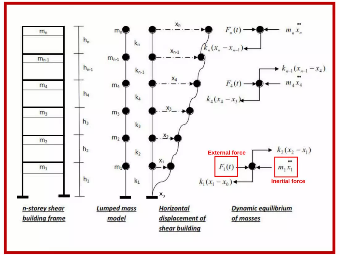
x0
Inertial force
External force


0
If the structure undergoes free body vibrations then the equation of motion is given by
or KX = -MX..
Or in vector notation we have

Substituting for X in the equation KX = -MX.. ..
The above is the governing equation for undamped free vibrations of a MDOF system
peak amplitude of vibration and x(t) is the amplitude at time ‘t’

Where 2 are the eigen values or natural frequencies of the system
02 MK
is known as the eigen value problem. The solution of this problem gives the natural frequencies or eigen values of the various mode shapes (i.e. modes of vibration of the oscillating system)
The natural time periods of the MDOF system are:
T =
nT
TT
2
1
.
An ‘n’ degree of freedom system will have ‘n’ natural frequencies and hence ‘n’ modes of vibration. In Each mode of vibration, the structure will have a certain deformed shape which is called as the mode shape.

Corresponding to each natural frequency the system assumes a certain deformation profile called as its mode shape. The system will have as many as natural frequencies and mode shapes as its degrees of freedom [X] is called as the eigen vector /modal vector or the mode shape. The mode shapes corresponding to the natural frequencies ω1, ω2, - - - - ωn-1 and ωn are found from the following equations:
.
The eigen vector/ modal vector/ mode shape vector X is written as:
[X] nn 1321 ..
First mode shape corresponding to the fundamental natural frequency ω1
Second mode shape corresponding to the natural frequency ω2

For example, the first mode shape of a four storey building will be:
4a
This building has four degrees of freedom and there will be four natural frequencies and four modes of vibration. The four mode shapes are φ1, φ2, φ3 and φ4 .
Hence, the eigen vector to some scale is written as:
Displaced shape of the structure corresponding to the fourth mode shape


The above method is also called as the square root of the sum of squares (SRSS)

Example:Find the eigen-values and mode shapes of the simple RCC frame shown below:
Ec = 27600 MPa Moment of inertia of column, I = 5 X 109 mm4
Assumptions:
1) Moment of inertia or flexural stiffness of the beams is infinite hence the beams do not undergo any bending.
2) Axial stiffness of the columns it is very large hence there is no sway of the frame due to shortening or lengthening of the columns.
3) Lateral deflection of the frame is only due to column bending
4.6 m
4.6 m
Seismic weight = W2 = 2600 kN
Seismic weight = W1 = 2600 kN
W2
W1

To find the mass matrix
W1 = W2 = 2600KN
W = mg or gWm
m1 = m2 = 81.910002600 = 265036 kg = 265T
Mass matrix = [M] =
2
1
00m
m=
26500265
To find the stiffness matrix
Stiffness of each column= K = 3
12LEI
K= 3
9
46001052760012 = 17013 N/mm say 17000 N/mm ( for each column)
Stiffness matrix = [K] =
22
221
kkkkk
=
34000340003400068000

The eigen-value problem is 02 MK
34000340003400068000 - 2
26500265 = 0
26534000340003400026568000
2
2
= 0 or
2221
1211
aaaa
= 0
The determinant is given by 12212211 aaaa
If 2 then
(68000-265 )(34000-265 )-(-34000)(-34000)
Setting the determinant equal to zero gives a quadratic in
2 -385 +16461=0
Solving we get
211 = 49 or 1 =7 rads/s
222 =336 or 2 =18.33 rads/s

To find the time period
T1=1
2 =0.897s
T2=2
2 =0.342s
To find the mode shapes
Substitute known values into the following characteristic equation
02 XMK
Where X is the eigen vector written as
X = 21
Where 1 is the first mode shape and 2 is the second mode shape Substituting first for 2
1 we get the first mode shape
265)49(3400034000
34000265)49(68000
21
11
=
00
21015340003400055015
21
11
=
00
2111 3400055015 or 2111 62.0
2111 2101534000 or 2111 62.0
If 21 =1 , then 11 =0.62
First mode shape
m2
m1
11 =0.62
21 =1
Fundamental mode of vibration
The first mode time period is numerically the largest value and is called as the fundamental period of vibration of the structure.
This is the vector φ1

Substituting for 22 we get second mode shape
265)336(3400034000
34000265)336(68000
22
12
=
00
55040340003400021040
22
12
=
00
2212 3400021040 or 2212 61.1
2212 5504034000 or 2212 61.1
If 22 =1 , then 12 =-1.61
m2
m1 Second mode shape
22 =1
12 =-1.61
This is the vector φ2

Note that for calculation of seismic weight 50% of the live load shall be assumed on all floors and zero live load on roof

Typical column = 0.45 m x 0.45 m
Typical beam,0.3m x 0.45 m
Typical slabpanel 0.15 m thick

m1 0 0
0 m2 0
0 0 m3

(Number of columns in each storey = 28)
k1+k2 - k2 0
- k2 k2+k3 - k3
0 - k3 k3
Note that lateral displacement of the frame isonly due to flexural deformations of the columns
= k1 = k2 = k3

Note that the number of degrees of freedom of the system = 3. Hence, it will havethree natural frequencies and three mode shapes or three modes of oscillation
Mode 1
Mode 2
Mode 3
We can also use ETABS or SAP to find the eigen values

ω for the first mode
Setting the displacement at the level of the first storey to be unity

ω for the second mode


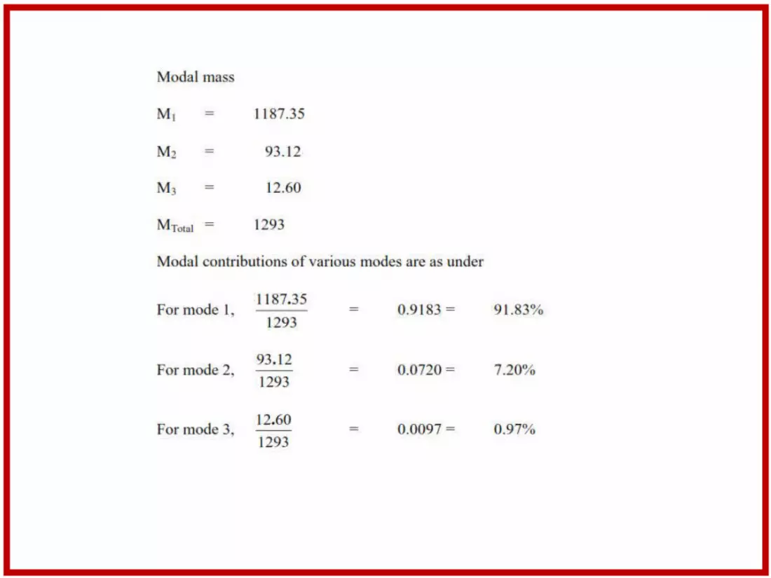

Modal participation factor for the kth mode
Mode shape for the kth mode

Pk for first mode
Ak
WiΦik for first mode
1 storey
2 storey
3 storey
Q11
Q21
Q31
Q12
Q22
Q32
Q13
Q23
Q33
1 storey
1 storey
2 storey
2 storey
3 storey
3 storey

Base shear
Base shear
Base shear

Storey shear in the first floor or the base shear is
Storey shear in the second floor is
Storey shear in the third floor is

(Equivalent static base shear)

Note that the number of parallel plane framesin the short direction = 7. Hence, 251.81/7 = 35.97
Note that the number of parallel plane framesin the short direction = 4. Hence, 251.81/4= 62.95


Non-ductile detailing of R.C. structures

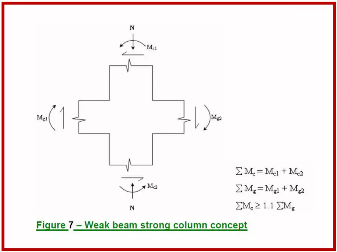
Envelope bending moment diagram for a beam in a moment resistant frame


ld
ld
300
300


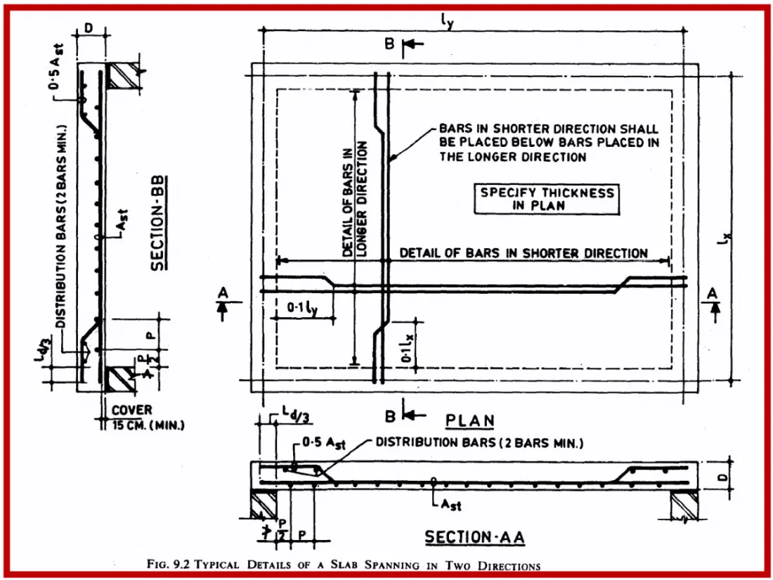

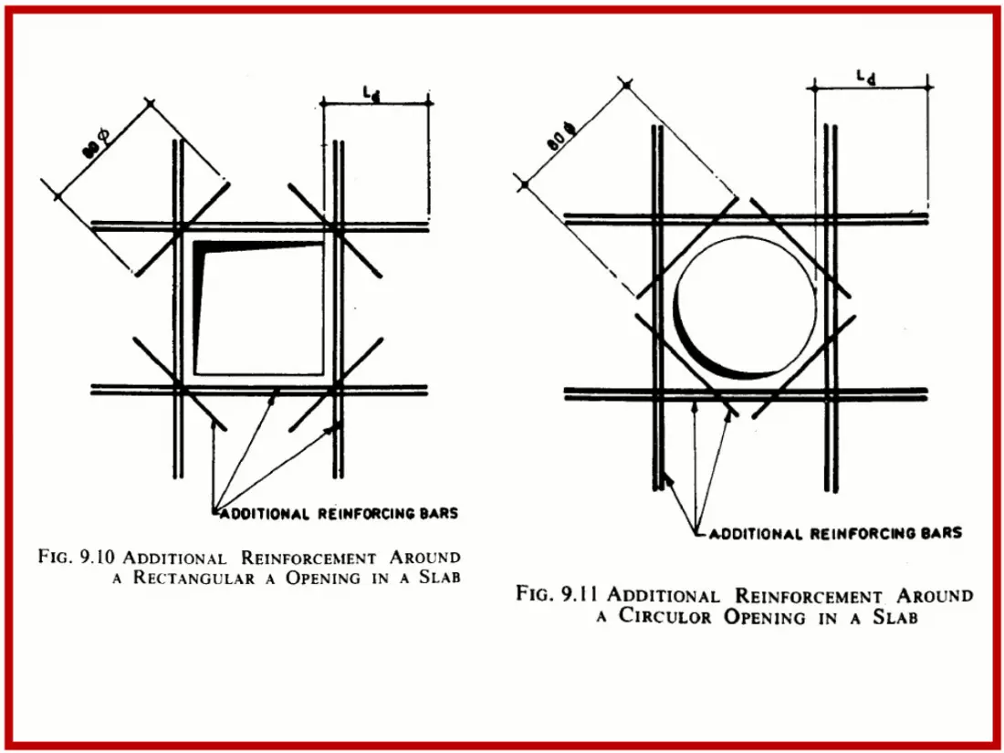
Rules for curtailment of reinforcement in continuous slabs


Arrangement of transverse reinforcement in columns


Joggled or draped bars


Min. Ast = 3 nos. 10 mm
6 mm at 300 c/c

Ductile Detailing of R.C. Structures per IS 13920


Otherwise the member will be undersignificant compression and has to be designed as a beam column
It is difficult to confine concrete with the help of stirrups in narrow beams
For ease of placement of longitudinal steelTo ensure that Bernoulli’s bending theory (plane sections remaining plane) holds good
Under earthquake loads, zone of moment reversal may extend considerably into the span. Hence,min. steel should be present at all sections.
This is the minimum tension reinforcement requirement for a ductile design. When concrete cracks in tension, enough steel should be present to resist the tensile force
To avoid reinforcement congestion, max. amount of tension steel = 2.5%
To take care of reversal of seismic momentsSufficient steel should be present atany section to take care of reversal ofbending moments or bending moments due to unexpected loads

Compared to low-strength concrete, high-strength concrete is more brittle!

Tension steel at top
Tension steel at bottom
Tension steel at top
Envelope bending moment diagram
Tension steel at top
Tension steel at bottom

Detailing of minimum compression-face reinforcement in a beam
Compression steel is at least 50% of tension steel Compression steel is at least 50%
of tension steel


Detailing of a typicalseismic hook

Likely zone of hinge formation Likely zone of hinge formation
Confinement of concrete

Possible region of flexural yielding
Possible region of flexural yielding
Region of lap splice