Embed Size (px)
Citation preview
© Copyright 2015 Pearson Education, Inc. All rights reserved. This material is protected under all copyright laws as they currently exist. No portion of this material may be reproduced, in any form or by any means, without permission in writing from the publisher.
8-1
Q8.1. Reason: Because the definition of equilibrium includes 0τΣ = as well as 0,FΣ = an object that experiences exactly two forces that are equal in magnitude and opposite in direction may still not be in equilibrium because the forces could cause a net torque even though the sum of the forces is zero. See Figure 8.1. Furthermore, an object could even have 0τΣ = as well as 0FΣ = (and therefore be in equilibrium) but still not be in static equilibrium if it is moving at a constant velocity. Assess: Think carefully about the definition of equilibrium, especially what it doesn’t say.
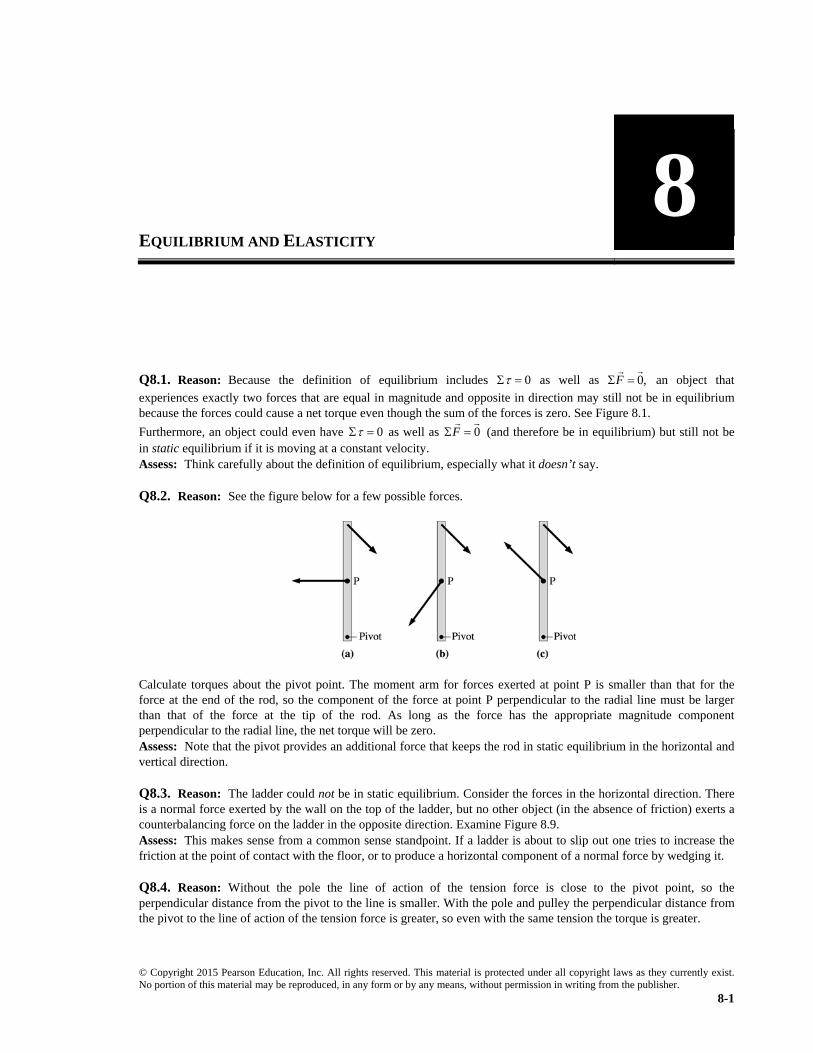
Q8.2. Reason: See the figure below for a few possible forces.
Calculate torques about the pivot point. The moment arm for forces exerted at point P is smaller than that for the force at the end of the rod, so the component of the force at point P perpendicular to the radial line must be larger than that of the force at the tip of the rod. As long as the force has the appropriate magnitude component perpendicular to the radial line, the net torque will be zero. Assess: Note that the pivot provides an additional force that keeps the rod in static equilibrium in the horizontal and vertical direction.
Q8.3. Reason: The ladder could not be in static equilibrium. Consider the forces in the horizontal direction. There is a normal force exerted by the wall on the top of the ladder, but no other object (in the absence of friction) exerts a counterbalancing force on the ladder in the opposite direction. Examine Figure 8.9. Assess: This makes sense from a common sense standpoint. If a ladder is about to slip out one tries to increase the friction at the point of contact with the floor, or to produce a horizontal component of a normal force by wedging it.
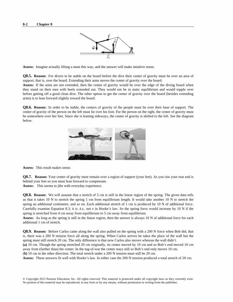
Q8.4. Reason: Without the pole the line of action of the tension force is close to the pivot point, so the perpendicular distance from the pivot to the line is smaller. With the pole and pulley the perpendicular distance from the pivot to the line of action of the tension force is greater, so even with the same tension the torque is greater.
EQUILIBRIUM AND ELASTICITY
8
8-2 Chapter 8
© Copyright 2015 Pearson Education, Inc. All rights reserved. This material is protected under all copyright laws as they currently exist. No portion of this material may be reproduced, in any form or by any means, without permission in writing from the publisher.
Assess: Imagine actually lifting a mast this way, and the answer will make intuitive sense.
Q8.5. Reason: For divers to be stable on the board before the dive their center of gravity must be over an area of support, that is, over the board. Extending their arms moves the center of gravity over the board. Assess: If the arms are not extended, then the center of gravity would be over the edge of the diving board when they stand on their toes with heels extended out. They would not be in static equilibrium and would topple over before getting off a good clean dive. The other option to get the center of gravity over the board (besides extending arms) is to lean forward slightly toward the board.
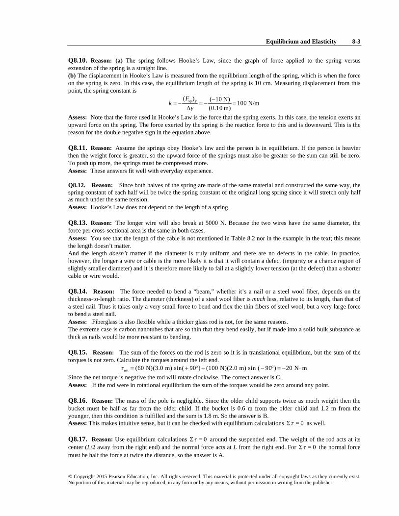
Q8.6. Reason: In order to be stable, the centers of gravity of the people must lie over their base of support. The center of gravity of the person on the left must lie over his foot. For the person on the right, the center of gravity must be somewhere over her feet. Since she is leaning sideways, the center of gravity is shifted to the left. See the diagram below.
Assess: This result makes sense.
Q8.7. Reason: Your center of gravity must remain over a region of support (your feet). As you rise your rear end is behind your feet so you must lean forward to compensate. Assess: This seems to jibe with everyday experience.
Q8.8. Reason: We will assume that a stretch of 5 cm is still in the linear region of the spring. The given data tells us that it takes 10 N to stretch the spring 1 cm from equilibrium length. It would take another 10 N to stretch the spring an additional centimeter, and so on. Each additional stretch of 1 cm is produced by 10 N of additional force. Carefully examine Equation 8.3; it is ,xΔ not x in Hooke’s law. So the spring force would increase by 10 N if the spring is stretched from 4 cm away from equilibrium to 5 cm away from equilibrium. Assess: As long as the spring is still in the linear region, then the answer is always 10 N of additional force for each additional 1 cm of stretch.
Q8.9. Reason: Before Carlos came along the wall also pulled on the spring with a 200 N force when Bob did, that is, there was a 200 N tension force all along the spring. When Carlos arrives he takes the place of the wall but the spring must still stretch 20 cm. The only difference is that now Carlos also moves whereas the wall didn’t. (a) 10 cm. Though the spring stretched 20 cm originally, its center moved by 10 cm and so Bob’s end moved 10 cm away from (farther than) the center. In the tug-of-war the center stays still so Bob’s end only moves 10 cm. (b) 10 cm in the other direction. The total stretch under a 200 N tension must still be 20 cm. Assess: These answers fit well with Hooke’s law. In either case the 200 N tension produced a total stretch of 20 cm.
Equilibrium and Elasticity 8-3
© Copyright 2015 Pearson Education, Inc. All rights reserved. This material is protected under all copyright laws as they currently exist. No portion of this material may be reproduced, in any form or by any means, without permission in writing from the publisher.
Q8.10. Reason: (a) The spring follows Hooke’s Law, since the graph of force applied to the spring versus extension of the spring is a straight line. (b) The displacement in Hooke’s Law is measured from the equilibrium length of the spring, which is when the force on the spring is zero. In this case, the equilibrium length of the spring is 10 cm. Measuring displacement from this point, the spring constant is
sp( ) ( 10 N) 100 N/m(0.10 m)
yFk
y−
= − = − =Δ
Assess: Note that the force used in Hooke’s Law is the force that the spring exerts. In this case, the tension exerts an upward force on the spring. The force exerted by the spring is the reaction force to this and is downward. This is the reason for the double negative sign in the equation above.
Q8.11. Reason: Assume the springs obey Hooke’s law and the person is in equilibrium. If the person is heavier then the weight force is greater, so the upward force of the springs must also be greater so the sum can still be zero. To push up more, the springs must be compressed more. Assess: These answers fit well with everyday experience.
Q8.12. Reason: Since both halves of the spring are made of the same material and constructed the same way, the spring constant of each half will be twice the spring constant of the original long spring since it will stretch only half as much under the same tension. Assess: Hooke’s Law does not depend on the length of a spring.
Q8.13. Reason: The longer wire will also break at 5000 N. Because the two wires have the same diameter, the force per cross-sectional area is the same in both cases. Assess: You see that the length of the cable is not mentioned in Table 8.2 nor in the example in the text; this means the length doesn’t matter. And the length doesn’t matter if the diameter is truly uniform and there are no defects in the cable. In practice, however, the longer a wire or cable is the more likely it is that it will contain a defect (impurity or a chance region of slightly smaller diameter) and it is therefore more likely to fail at a slightly lower tension (at the defect) than a shorter cable or wire would.
Q8.14. Reason: The force needed to bend a “beam,” whether it’s a nail or a steel wool fiber, depends on the thickness-to-length ratio. The diameter (thickness) of a steel wool fiber is much less, relative to its length, than that of a steel nail. Thus it takes only a very small force to bend and flex the thin fibers of steel wool, but a very large force to bend a steel nail. Assess: Fiberglass is also flexible while a thicker glass rod is not, for the same reasons. The extreme case is carbon nanotubes that are so thin that they bend easily, but if made into a solid bulk substance as thick as nails would be more resistant to bending.
Q8.15. Reason: The sum of the forces on the rod is zero so it is in translational equilibrium, but the sum of the torques is not zero. Calculate the torques around the left end.
net (60 N)(3.0 m) sin( 90 ) (100 N)(2.0 m) sin ( 90 ) 20 N mτ = + ° + − ° = − ⋅ Since the net torque is negative the rod will rotate clockwise. The correct answer is C. Assess: If the rod were in rotational equilibrium the sum of the torques would be zero around any point.
Q8.16. Reason: The mass of the pole is negligible. Since the older child supports twice as much weight then the bucket must be half as far from the older child. If the bucket is 0.6 m from the older child and 1.2 m from the younger, then this condition is fulfilled and the sum is 1.8 m. So the answer is B. Assess: This makes intuitive sense, but it can be checked with equilibrium calculations = 0τΣ as well.
Q8.17. Reason: Use equilibrium calculations = 0τΣ around the suspended end. The weight of the rod acts at its center (L/2 away from the right end) and the normal force acts at L from the right end. For = 0τΣ the normal force must be half the force at twice the distance, so the answer is A.
8-4 Chapter 8
© Copyright 2015 Pearson Education, Inc. All rights reserved. This material is protected under all copyright laws as they currently exist. No portion of this material may be reproduced, in any form or by any means, without permission in writing from the publisher.
Assess: For = 0FΣ the tension in the suspension string must also be 7.0 N. This also makes sense when computing the torques around the center of the rod.
Q8.18. Reason: Assume the weight of the board can be neglected. The student’s weight exerts a downward force on the board, and the two scales exert an upward force on the board. See the diagram.
There is no net force on the board in the vertical direction. Solving the second equation in Equation 8.1 gives
1 2 (65 lb) (100 lb) 165 lbw F F= + = + = The correct choice is D. Assess: Note that the scale on the right exerts a larger force since the center of mass of the student is closer to the right scale.
Q8.19. Reason: The fact that the board is “very light” means we will neglect its mass (which we weren’t given anyway). We know that the student weighs 165 lbs because the downward force of gravity on the student must equal the upward sum of the two scale readings for the student to be in equilibrium. Also required for equilibrium is 0τΣ = and we are free to choose the axis around which we compute the torques anywhere we want. It would be most convenient to select a point above one of the scales so that the upward normal force due to that scale will not produce a torque. Furthermore, since we want to know the distance from the right hand scale, choose it as the pivot.
(165 lb) (2.0 m)(65 lb) 0 lb mdτΣ = − = ⋅
where the counterclockwise torque is positive and the clockwise torque is negative: (2.0 m)(65 lb) 0.79 m 0.8 m
165 lbd = = ≈
So the correct choice is B. Assess: Not only could we have chosen the pivot point at the left scale and produced the same answer (using L – d as the lever arm), but we should do so as a check.
(2.0 m)(100 lb) ( )(165 lb) 0 lb m(2.0 m)(100 lb)
165 lb(2.0 m)(100 lb)2.0 m 0.79 m 0.8 m
165 lb
L d
L d
d
τΣ = − − = ⋅
− =
= − = ≈
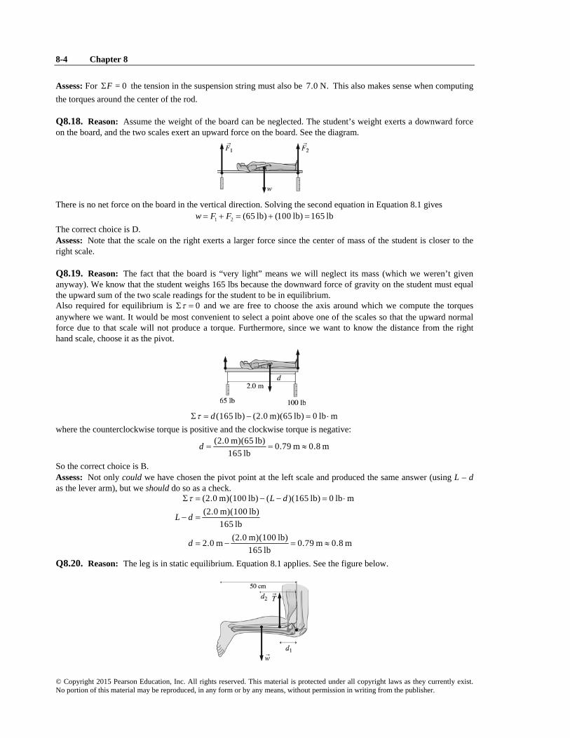
Q8.20. Reason: The leg is in static equilibrium. Equation 8.1 applies. See the figure below.
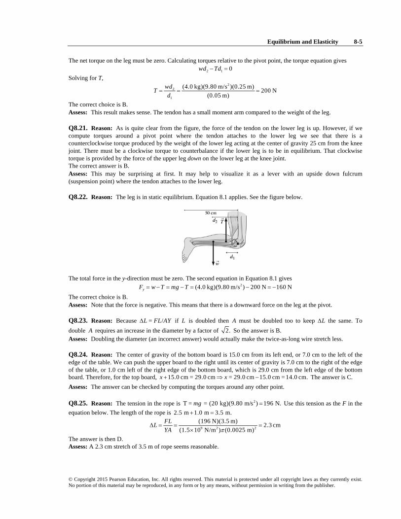
Equilibrium and Elasticity 8-5
© Copyright 2015 Pearson Education, Inc. All rights reserved. This material is protected under all copyright laws as they currently exist. No portion of this material may be reproduced, in any form or by any means, without permission in writing from the publisher.
The net torque on the leg must be zero. Calculating torques relative to the pivot point, the torque equation gives 2 1 0wd Td− =
Solving for T, 2
2
1
(4.0 kg)(9.80 m/s )(0.25 m) 200 N(0.05 m)
wdTd
= = =
The correct choice is B. Assess: This result makes sense. The tendon has a small moment arm compared to the weight of the leg.
Q8.21. Reason: As is quite clear from the figure, the force of the tendon on the lower leg is up. However, if we compute torques around a pivot point where the tendon attaches to the lower leg we see that there is a counterclockwise torque produced by the weight of the lower leg acting at the center of gravity 25 cm from the knee joint. There must be a clockwise torque to counterbalance if the lower leg is to be in equilibrium. That clockwise torque is provided by the force of the upper leg down on the lower leg at the knee joint. The correct answer is B. Assess: This may be surprising at first. It may help to visualize it as a lever with an upside down fulcrum (suspension point) where the tendon attaches to the lower leg.
Q8.22. Reason: The leg is in static equilibrium. Equation 8.1 applies. See the figure below.
The total force in the y-direction must be zero. The second equation in Equation 8.1 gives 2(4.0 kg)(9.80 m/s ) 200 N 160 NyF w T mg T= − = − = − = −
The correct choice is B. Assess: Note that the force is negative. This means that there is a downward force on the leg at the pivot.
Q8.23. Reason: Because = /L FL AYΔ if L is doubled then A must be doubled too to keep LΔ the same. To double A requires an increase in the diameter by a factor of 2. So the answer is B. Assess: Doubling the diameter (an incorrect answer) would actually make the twice-as-long wire stretch less.
Q8.24. Reason: The center of gravity of the bottom board is 15.0 cm from its left end, or 7.0 cm to the left of the edge of the table. We can push the upper board to the right until its center of gravity is 7.0 cm to the right of the edge of the table, or 1.0 cm left of the right edge of the bottom board, which is 29.0 cm from the left edge of the bottom board. Therefore, for the top board, 15.0 cm = 29.0 cm = 29.0 cm 15.0 cm = 14.0 cm.x x+ ⇒ − The answer is C. Assess: The answer can be checked by computing the torques around any other point.
Q8.25. Reason: The tension in the rope is 2T = = (20 kg)(9.80 m/s ) 196 N .mg = Use this tension as the F in the equation below. The length of the rope is 2.5 m 1.0 m 3.5 m.+ =
9 2 2
(196 N)(3.5 m) 2.3 cm(1.5 10 N/m ) (0.0025 m)
FLLYA π
Δ = = =×
The answer is then D. Assess: A 2.3 cm stretch of 3.5 m of rope seems reasonable.
8-6 Chapter 8
© Copyright 2015 Pearson Education, Inc. All rights reserved. This material is protected under all copyright laws as they currently exist. No portion of this material may be reproduced, in any form or by any means, without permission in writing from the publisher.
Problems
P8.1. Prepare: Because the board is “very light” we will assume that it is massless and does not contribute to the scale reading, nor does it contribute any torques. The sum of the two scale readings must equal the woman’s weight:
2(64 kg)(9.80 m/s ) 627 N 630 N.w mg= = = ≈ Solve: Compute the torques around the point the board rests on the left scale. The woman’s weight creates a clockwise (negative) torque; and the normal force rightn of the right scale creates a counterclockwise (positive) torque.
right(2.0 m)( ) (1.5 m)(627 N) 0 N mnτΣ = − = ⋅
The right scale reads right:n
right(1.5 m)(627 N) 470 N
2.0 mn = =
By simple subtraction the left scale reads left 627 N 470 N 160 Nn = − =
Assess: The answer is reasonable. Since the woman is three times farther from the left scale than the right one, it (the left one) reads three times less. And the two scale readings sum to the woman’s weight, as required. Not only could we have chosen the pivot point at the right scale and produced the same answer, but we should do so as a check.
left
left
(0.5 m)(627 N) (2.0 m)( ) 0 N m(0.5 m)(627 N) 160 N
2.0 m
n
n
τΣ = − = ⋅
= =
And so
right 627 N 157 N 470 Nn = − = It is true that 0τΣ = around any point (for equilibrium), but we picked the two we did (the second as a check) because then the resulting torque equations each had only one unknown in them.
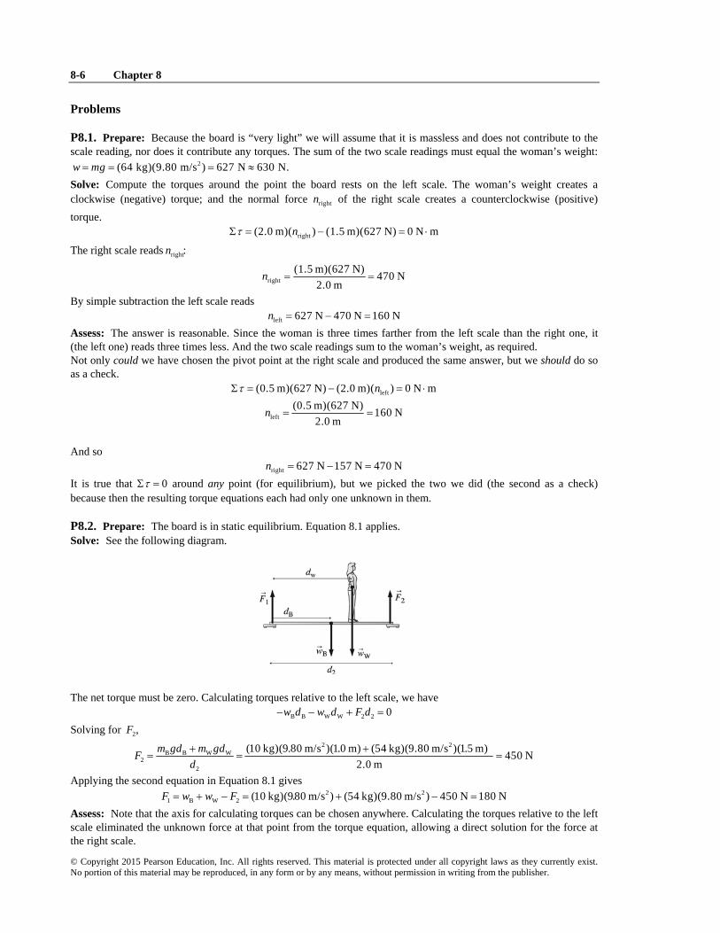
P8.2. Prepare: The board is in static equilibrium. Equation 8.1 applies. Solve: See the following diagram.
The net torque must be zero. Calculating torques relative to the left scale, we have B B W W 2 2 0w d w d F d− − + =
Solving for 2,F 2 2
B B W W2
2
(10 kg)(9.80 m/s )(1.0 m) (54 kg)(9.80 m/s )(1.5 m) 450 N2.0 m
m gd m gdFd+ +
= = =
Applying the second equation in Equation 8.1 gives 2 2
1 B W 2 (10 kg)(9.80 m/s ) (54 kg)(9.80 m/s ) 450 N 180 NF w w F= + − = + − = Assess: Note that the axis for calculating torques can be chosen anywhere. Calculating the torques relative to the left scale eliminated the unknown force at that point from the torque equation, allowing a direct solution for the force at the right scale.
Equilibrium and Elasticity 8-7
© Copyright 2015 Pearson Education, Inc. All rights reserved. This material is protected under all copyright laws as they currently exist. No portion of this material may be reproduced, in any form or by any means, without permission in writing from the publisher.
P8.3. Prepare: Compute the torques around the bottom of the right leg of the table. The horizontal distance from
there to the center of gravity of the table is 2.10 m = 0.55 m = 0.50 m.2
Solve: Call the horizontal distance from the bottom of the right leg to the center of gravity of the man x. 2 2(56 kg)(9.8 m/s )(0.50 m) (70 kg)(9.8 m/s ) 0 0.40 mx xτΣ = − = ⇒ =
The distance from the right edge of the table is now 0.55 m 0.40 m = 0.15 m = 15 cm.−
Assess: It seems likely that the table would tip if the man were closer than 15 cm to the edge.
P8.4. Prepare: When the beam just starts to tip, the left support will not exert any upward force on the beam. Simply apply the = 0FΣ equilibrium condition. Solve: The net force must be zero, so the right support must exert an upward force equal to the combined weight.
2(10 kg 70 kg)(9.80 m/s ) = 780 N+ Assess: Because the force of the left support is zero we did not need to use the = 0τΣ condition.
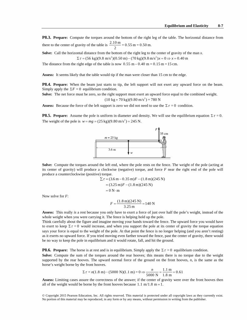
P8.5. Prepare: Assume the pole is uniform in diameter and density. We will use the equilibrium equation = 0.τΣ The weight of the pole is 2(25 kg)(9.80 m/s ) 245 N.w mg= = =
Solve: Compute the torques around the left end, where the pole rests on the fence. The weight of the pole (acting at its center of gravity) will produce a clockwise (negative) torque, and force F near the right end of the pole will produce a counterclockwise (positive) torque.
(3.6 m 0.35 m) (1.8 m)(245 N)(3.25 m) (1.8 m)(245 N)0 N m
FF
τ∑ = − −= −= ⋅
Now solve for F: (1.8 m)(245 N) 140 N
3.25 mF = =
Assess: This really is a rest because you only have to exert a force of just over half the pole’s weight, instead of the whole weight when you were carrying it. The fence is helping hold up the pole. Think carefully about the figure and imagine moving your hands toward the fence. The upward force you would have to exert to keep = 0τΣ would increase, and when you support the pole at its center of gravity the torque equation says your force is equal to the weight of the pole. At that point the fence is no longer helping (and you aren’t resting) as it exerts no upward force. If you tried moving even farther toward the fence, past the center of gravity, there would be no way to keep the pole in equilibrium and it would rotate, fall, and hit the ground.
P8.6. Prepare: The horse is at rest and is in equilibrium. Simply apply the = 0τΣ equilibrium condition. Solve: Compute the sum of the torques around the rear hooves; this means there is no torque due to the weight supported by the rear hooves. The upward normal force of the ground on the front hooves, n, is the same as the horse’s weight borne by the front hooves.
1.1 m= (1.8 m) (5000 N)(1.1 m) = 0 0.615000 N 1.8 m
nnτΣ − ⇒ = =
Assess: Limiting cases assure the correctness of the answer; if the center of gravity were over the front hooves then all of the weight would be borne by the front hooves because 1.1 m/1.8 m 1.=
8-8 Chapter 8
© Copyright 2015 Pearson Education, Inc. All rights reserved. This material is protected under all copyright laws as they currently exist. No portion of this material may be reproduced, in any form or by any means, without permission in writing from the publisher.
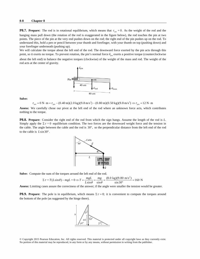
P8.7. Prepare: The rod is in rotational equilibrium, which means that net = 0.τ As the weight of the rod and the hanging mass pull down (the rotation of the rod is exaggerated in the figure below), the rod touches the pin at two points. The piece of the pin at the very end pushes down on the rod; the right end of the pin pushes up on the rod. To understand this, hold a pen or pencil between your thumb and forefinger, with your thumb on top (pushing down) and your forefinger underneath (pushing up). We will calculate the torque about the left end of the rod. The downward force exerted by the pin acts through this point, so it exerts no torque. To prevent rotation, the pin’s normal force pinn exerts a positive torque (counterclockwise about the left end) to balance the negative torques (clockwise) of the weight of the mass and rod. The weight of the rod acts at the center of gravity.
Solve:
2 2net pin pin0 N m (0.40 m)(2.0 kg)(9.8 m/s ) (0.80 m)(0.50 kg)(9.8 m/s ) 12 N mτ τ τ= ⋅ = − − ⇒ = ⋅
Assess: We carefully chose our pivot at the left end of the rod where an unknown force acts, which contributes nothing to the torque.
P8.8. Prepare: Consider the right end of the rod from which the sign hangs. Assume the length of the rod is L. Simply apply the = 0τΣ equilibrium condition. The two forces are the downward weight force and the tension in the cable. The angle between the cable and the rod is 30 ,° so the perpendicular distance from the left end of the rod to the cable is sin30 .L °
Solve: Compute the sum of the torques around the left end of the rod.
2(8.0 kg)(9.80 m/s )= ( sin ) = 0 160 Nsin sin sin30
mgL mgT L mgL TL
τ θθ θ
Σ − ⇒ = = = =°
Assess: Limiting cases assure the correctness of the answer; if the angle were smaller the tension would be greater.
P8.9. Prepare: The pole is in equilibrium, which means 0;τΣ = it is convenient to compute the torques around the bottom of the pole (as suggested by the hinge there).
Equilibrium and Elasticity 8-9
© Copyright 2015 Pearson Education, Inc. All rights reserved. This material is protected under all copyright laws as they currently exist. No portion of this material may be reproduced, in any form or by any means, without permission in writing from the publisher.
Solve: The angle between the left wire and the r up the pole is 27° and the angle between the right wire and the r halfway up the pole is 63°
LL R 2
R
sin63( sin 27 ) ( sin63 ) 0 1.02sin 27
h TT h TT
τ °Σ = ° − ° = ⇒ = =
°
Assess: Theoretically, the pole could be at rest in equilibrium if there were no wires, but any slight perturbation would make it fall over (an example of unstable equilibrium), and so guy wires are used which can keep the pole in equilibrium even if perturbed. Whether it is preferable to use guy wires like the one on the left or like the one on the right may depend on how much room around the base of the pole is available, and where one would rather attach the wires to the pole.
P8.10. Prepare: Following the example, let 0.040 m 0.96 md d′ = + = be the new distance from the pivot to the woman’s center of gravity. We want to know .F' Solve: Use the same rotational equilibrium equation from the example but solve for .F'
b2
2.5 mb2 2
0
(60 N) (0.96 m)(600 N) 260 N2.5 m
L
L
w d w LF
w d wF
L
τ ′ ′= − − + =
′+ +′ = = =
∑
Assess: It makes sense that raising (toward the right in the diagram) the center of gravity would increase the scale reading.
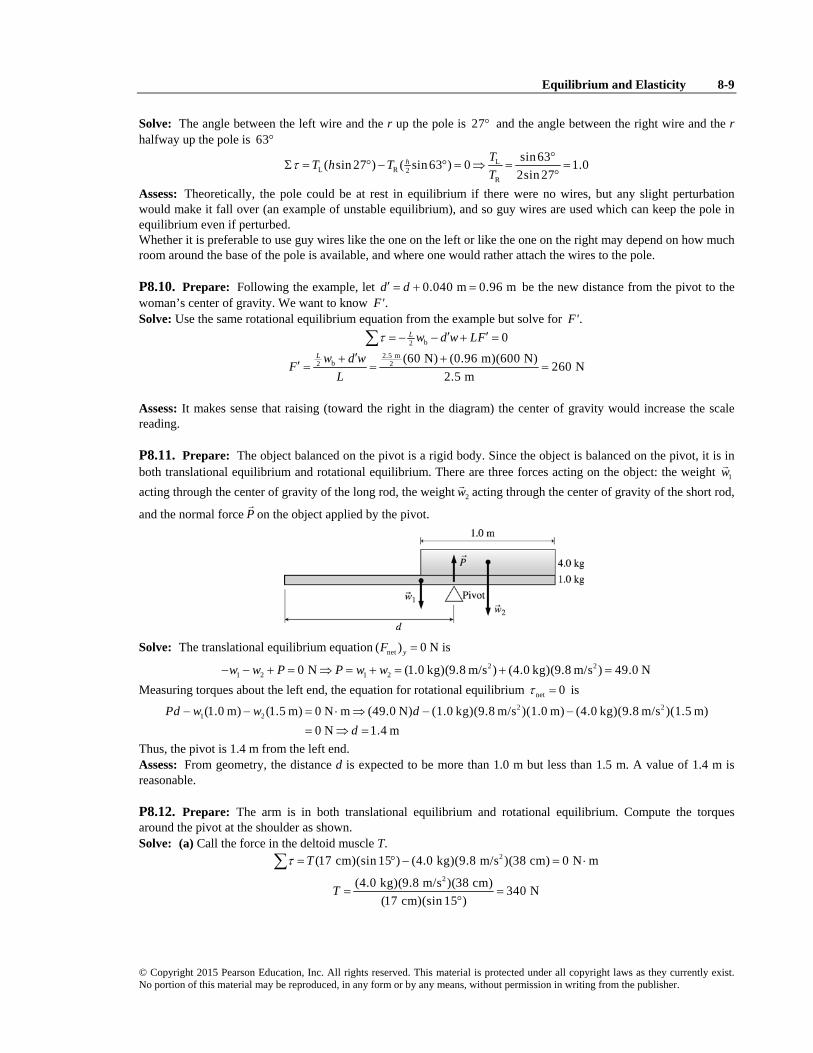
P8.11. Prepare: The object balanced on the pivot is a rigid body. Since the object is balanced on the pivot, it is in both translational equilibrium and rotational equilibrium. There are three forces acting on the object: the weight 1w acting through the center of gravity of the long rod, the weight 2w acting through the center of gravity of the short rod,
and the normal force P on the object applied by the pivot.
Solve: The translational equilibrium equation net( ) 0 NyF = is
2 21 2 1 20 N (1.0 kg)(9.8 m/s ) (4.0 kg)(9.8 m/s ) 49.0 Nw w P P w w− − + = ⇒ = + = + =
Measuring torques about the left end, the equation for rotational equilibrium net 0τ = is 2 2
1 2(1.0 m) (1.5 m) 0 N m (49.0 N) (1.0 kg)(9.8 m/s )(1.0 m) (4.0 kg)(9.8 m/s )(1.5 m)0 N 1.4 m
Pd w w dd
− − = ⋅ ⇒ − −= ⇒ =
Thus, the pivot is 1.4 m from the left end. Assess: From geometry, the distance d is expected to be more than 1.0 m but less than 1.5 m. A value of 1.4 m is reasonable.
P8.12. Prepare: The arm is in both translational equilibrium and rotational equilibrium. Compute the torques around the pivot at the shoulder as shown. Solve: (a) Call the force in the deltoid muscle T.
2
2
(17 cm)(sin 15 ) (4.0 kg)(9.8 m/s )(38 cm) 0 N m
(4.0 kg)(9.8 m/s )(38 cm) 340 N(17 cm)(sin 15 )
T
T
τ = ° − = ⋅
= =°
∑
8-10 Chapter 8
© Copyright 2015 Pearson Education, Inc. All rights reserved. This material is protected under all copyright laws as they currently exist. No portion of this material may be reproduced, in any form or by any means, without permission in writing from the publisher.
(b) Divide both sides of the previous equation by mg. (38 cm) 8.6
(17 cm)(sin 15 )T
mg= =
°
Thus, the deltoid muscle must be able to exert a force 8.6 times greater than the weight of the arm just to let you keep it outstretched at rest. Assess: Holding something in your hand would greatly increase the clockwise torque, so the force in the deltoid muscle would need to be even larger.
P8.13. Prepare: In this problem we are given the mass of the board, but because of the symmetry of the distances (the fulcrum, or right support, is right in the center) we don’t need it. We’ll compute the torques around the right support, which is under the center of gravity of the board, so the weight of the board won’t produce a torque. The weight of the diver is 2(60 kg)(9.80 m/s ) 590 N.w mg= = = Solve: Because of the symmetry of the situation (the two lever arms are equal in length), we can examine the torque equation in our heads and realize that the force exerted by the hinge must have the same magnitude as the weight of the diver. Therefore, the force the hinge exerts on the board is 590 N. Assess: We computed the torques around the right support because of the symmetry, but also because had we computed them around the hinge on the left, we would be eliminating from the equation the very torque we need to answer the problem. Since both the weight of the diver and the force of the hinge act in the downward direction, it is also clear that the right support must exert a force of twice the diver’s weight in the upward direction.
P8.14. Prepare: The arm is in both translational equilibrium and rotational equilibrium. Compute the torques around the pivot at the elbow as shown. All the forces are in the vertical direction. Solve: Call the force in the triceps muscle T.
(90 N)(30 cm)(90 N)(30 cm) (2.4 cm) 0 N m 1100 N2.4 cm
T Tτ = − = ⋅ ⇒ = =∑
Assess: This is a pretty big force, but not too hard for your triceps.
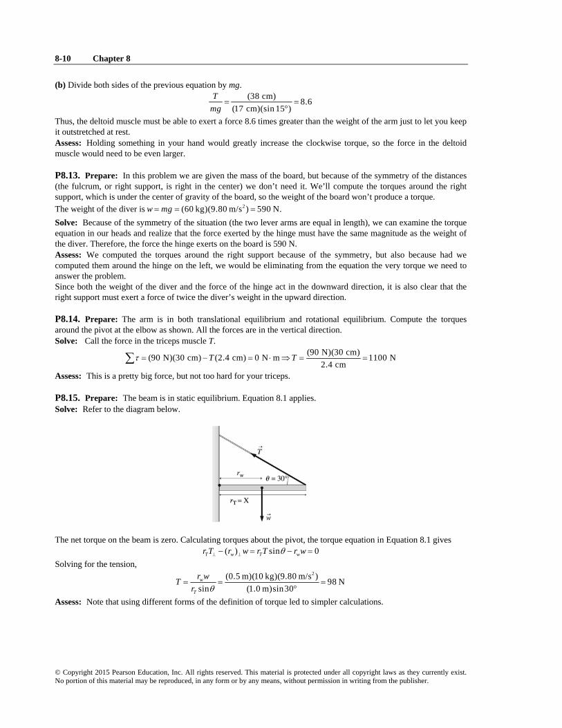
P8.15. Prepare: The beam is in static equilibrium. Equation 8.1 applies. Solve: Refer to the diagram below.
The net torque on the beam is zero. Calculating torques about the pivot, the torque equation in Equation 8.1 gives ( ) sin 0T w T wr T r w r T r wθ⊥ ⊥− = − =
Solving for the tension, 2(0.5 m)(10 kg)(9.80 m/s ) 98 N
sin (1.0 m)sin30w
T
r wTr θ
= = =°
Assess: Note that using different forms of the definition of torque led to simpler calculations.
Equilibrium and Elasticity 8-11
© Copyright 2015 Pearson Education, Inc. All rights reserved. This material is protected under all copyright laws as they currently exist. No portion of this material may be reproduced, in any form or by any means, without permission in writing from the publisher.
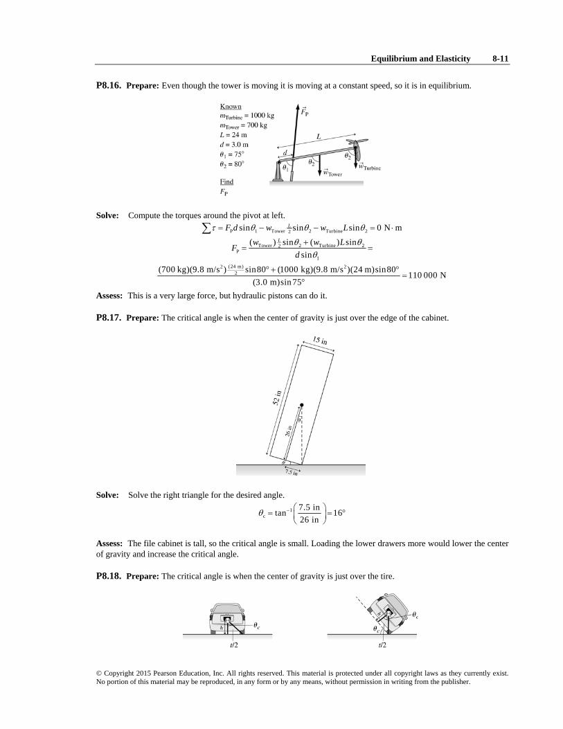
P8.16. Prepare: Even though the tower is moving it is moving at a constant speed, so it is in equilibrium.
Solve: Compute the torques around the pivot at left.
P 1 Tower 2 Turbine 22
Tower 2 Turbine 22P
1(24 m)2 2
2
sin sin sin 0 N m
( ) sin ( ) sinsin
(700 kg)(9.8 m/s ) sin80 (1000 kg)(9.8 m/s )(24 m)sin80 110 000 N(3.0 m)sin 75
L
L
F d w w L
w w LF
d
τ θ θ θ
θ θθ
= − − = ⋅
+= =
° + °=
°
∑
Assess: This is a very large force, but hydraulic pistons can do it.
P8.17. Prepare: The critical angle is when the center of gravity is just over the edge of the cabinet.
Solve: Solve the right triangle for the desired angle. 1
c7.5 intan 1626 in
θ − ⎛ ⎞= = °⎜ ⎟⎝ ⎠
Assess: The file cabinet is tall, so the critical angle is small. Loading the lower drawers more would lower the center of gravity and increase the critical angle.
P8.18. Prepare: The critical angle is when the center of gravity is just over the tire.
8-12 Chapter 8
© Copyright 2015 Pearson Education, Inc. All rights reserved. This material is protected under all copyright laws as they currently exist. No portion of this material may be reproduced, in any form or by any means, without permission in writing from the publisher.
Solve: From the digram we see that the Static Stability Factor (SSF) is equal to ctan( ).θ
( )1c tan 1.2 50θ −= = °
Assess: One can see that increasing the track width increases the stability of the SUV. More information is at http://www.suu.edu/faculty/penny/RolloverPaper/RolloverPaper.pdf.
P8.19. Prepare: As long as the center of gravity of the board is over one of the tables, the board will not tilt. Solve: See the figure below.
When the end of the board reaches the other table its center of gravity must still be over the first table, otherwise it will tilt. The board’s center of gravity should be 20 cm from one of its ends. Assuming the board is uniform, the board must be at least 40 cm long. Assess: For an object to be stable, the center of gravity of the object must lie over its base of support.
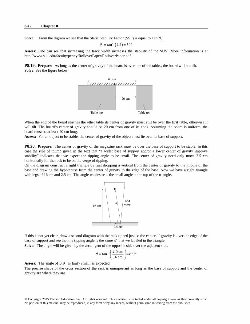
P8.20. Prepare: The center of gravity of the magazine rack must be over the base of support to be stable. In this case the rule of thumb given in the text that “a wider base of support and/or a lower center of gravity improve stability” indicates that we expect the tipping angle to be small. The center of gravity need only move 2.5 cm horizontally for the rack to be on the verge of tipping. On the diagram construct a right triangle by first dropping a vertical from the center of gravity to the middle of the base and drawing the hypotenuse from the center of gravity to the edge of the base. Now we have a right triangle with legs of 16 cm and 2.5 cm. The angle we desire is the small angle at the top of the triangle.
If this is not yet clear, draw a second diagram with the rack tipped just so the center of gravity is over the edge of the base of support and see that the tipping angle is the same θ that we labeled in the triangle. Solve: The angle will be given by the arctangent of the opposite side over the adjacent side.
1 2.5 cmtan 8.916 cm
θ − ⎛ ⎞= = °⎜ ⎟
⎝ ⎠
Assess: The angle of 8.9° is fairly small, as expected. The precise shape of the cross section of the rack is unimportant as long as the base of support and the center of gravity are where they are.
Equilibrium and Elasticity 8-13
© Copyright 2015 Pearson Education, Inc. All rights reserved. This material is protected under all copyright laws as they currently exist. No portion of this material may be reproduced, in any form or by any means, without permission in writing from the publisher.
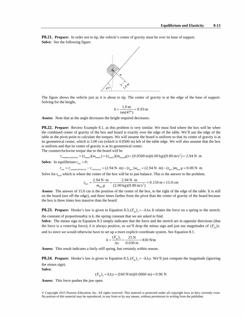
P8.21. Prepare: In order not to tip, the vehicle’s center of gravity must be over its base of support. Solve: See the following figure.
The figure shows the vehicle just as it is about to tip. The center of gravity is at the edge of the base of support. Solving for the height,
1.0 m 0.93 mtan(47 )
h = =°
Assess: Note that as the angle decreases the height required decreases.
P8.22. Prepare: Review Example 8.1, as this problem is very similar. We must find where the box will be when the combined center of gravity of the box and board is exactly over the edge of the table. We’ll use the edge of the table as the pivot point to calculate the torques. We will assume the board is uniform so that its center of gravity is at its geometrical center, which is 5.00 cm (which is 0.0500 m) left of the table edge. We will also assume that the box is uniform and that its center of gravity is at its geometrical center. The counterclockwise torque due to the board will be
2counterclockwise board board board board( )( ) ( )( ) (0.0500 m)(6.00 kg)(9.80 m/s ) 2.94 N mr w r m gτ = = = = ⋅
Solve: In equilibrium net 0:τ =
net counterclockwise clockwise box box box box(2.94 N m) ( ) (2.94 N m) ( ) 0.00 N mr w r m gτ τ τ= − = ⋅ − = ⋅ − = ⋅ Solve for box,r which is where the center of the box will be to just balance. This is the answer to the problem.
box 2box
2.94 N m 2.94 N m 0.150 m 15.0 cm(2.00 kg)(9.80 m/s )
rm g
⋅ ⋅= = = =
Assess: The answer of 15.0 cm is the position of the center of the box, to the right of the edge of the table. It is still on the board (not off the edge), and three times farther from the pivot than the center of gravity of the board because the box is three times less massive than the board.
P8.23. Prepare: Hooke’s law is given in Equation 8.3, sp( ) .xF k x= − Δ It relates the force on a spring to the stretch; the constant of proportionality is k, the spring constant that we are asked to find. Solve: The minus sign in Equation 8.3 simply indicates that the force and the stretch are in opposite directions (that the force is a restoring force); k is always positive, so we’ll drop the minus sign and just use magnitudes of sp( )F x and xΔ since we would otherwise have to set up a more explicit coordinate system. See Equation 8.1.
sp( ) 25 N 830 N/m0.030 m
xFk
x= = =
Δ
Assess: This result indicates a fairly stiff spring, but certainly within reason.
P8.24. Prepare: Hooke’s law is given in Equation 8.3, sp( ) .yF k y= − Δ We’ll just compute the magnitude (ignoring the minus sign). Solve:
sp( ) (160 N/m)(0.0060 m) 0.96 NyF k y= Δ = =
Assess: This force pushes the jaw open.
8-14 Chapter 8
© Copyright 2015 Pearson Education, Inc. All rights reserved. This material is protected under all copyright laws as they currently exist. No portion of this material may be reproduced, in any form or by any means, without permission in writing from the publisher.
P8.25. Prepare: For small displacements, the DNA obeys Hooke’s law, Equation 8.3. Solve: The force the DNA exerts is equal and opposite to the force the tweezers exert. See the figure below.
Applying Equation 8.3, 9
sp9
1.5 10 N 0.30 N/m5.0 10 m
Fk
x
−
−
− ×= − = − =
Δ ×
Assess: Note that Equation 8.3 refers to the force the spring exerts, not the force applied to the spring.
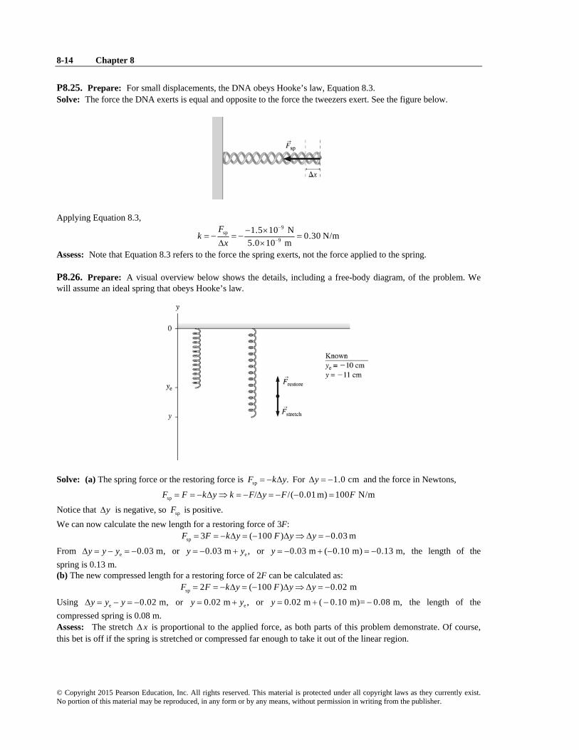
P8.26. Prepare: A visual overview below shows the details, including a free-body diagram, of the problem. We will assume an ideal spring that obeys Hooke’s law.
Solve: (a) The spring force or the restoring force is sp .F k y= − Δ For 1.0 cmyΔ = − and the force in Newtons,
sp / /( 0.01 m) 100 N/mF F k y k F y F F= = − Δ ⇒ = − Δ = − − =
Notice that yΔ is negative, so spF is positive. We can now calculate the new length for a restoring force of 3F:
sp 3 ( 100 ) 0.03 mF F k y F y y= = − Δ = − Δ ⇒ Δ = −
From e 0.03 m,y y yΔ = − = − or e0.03 m ,y y= − + or 0.03 m ( 0.10 m) 0.13 m,y = − + − = − the length of the spring is 0.13 m. (b) The new compressed length for a restoring force of 2F can be calculated as:
sp 2 ( 100 ) 0.02 mF F k y F y y= = − Δ = − Δ ⇒ Δ = −
Using e 0.02 m,y y yΔ = − = − or e0.02 m ,y y= + or 0.02 m ( 0.10 m)= 0.08 m,y = + − − the length of the compressed spring is 0.08 m. Assess: The stretch xΔ is proportional to the applied force, as both parts of this problem demonstrate. Of course, this bet is off if the spring is stretched or compressed far enough to take it out of the linear region.
Equilibrium and Elasticity 8-15
© Copyright 2015 Pearson Education, Inc. All rights reserved. This material is protected under all copyright laws as they currently exist. No portion of this material may be reproduced, in any form or by any means, without permission in writing from the publisher.
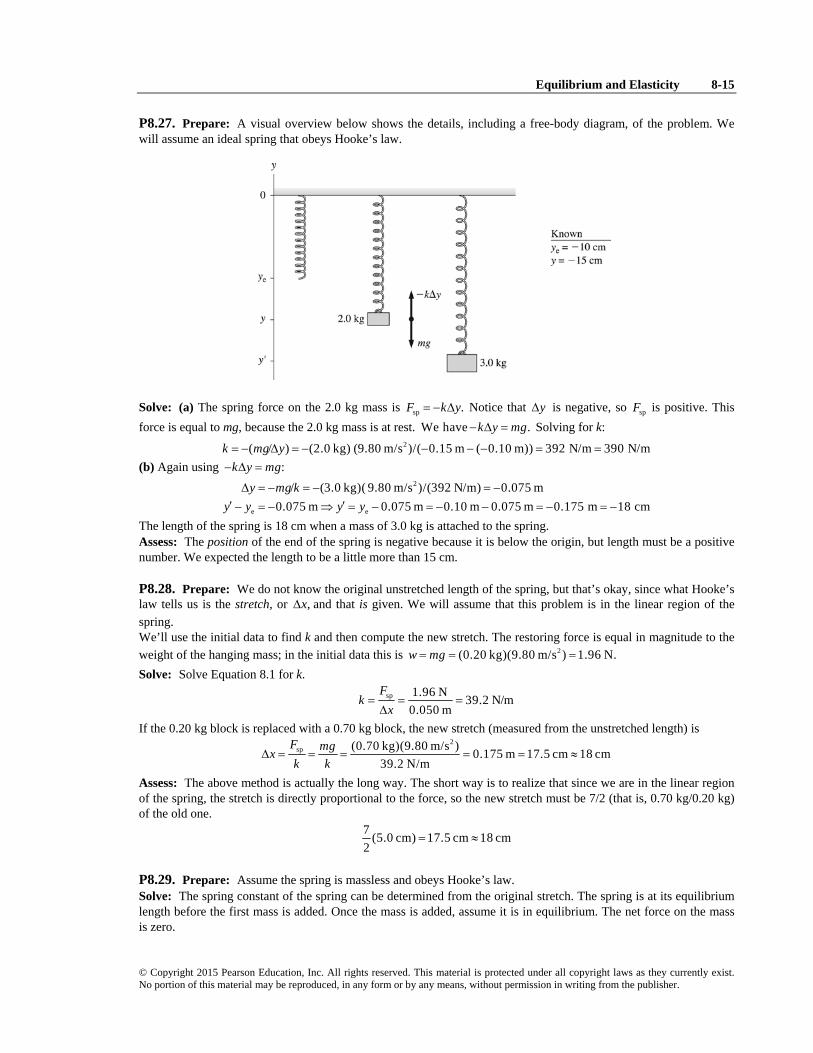
P8.27. Prepare: A visual overview below shows the details, including a free-body diagram, of the problem. We will assume an ideal spring that obeys Hooke’s law.
Solve: (a) The spring force on the 2.0 kg mass is sp .F k y= − Δ Notice that yΔ is negative, so spF is positive. This force is equal to mg, because the 2.0 kg mass is at rest. We have .k y mg− Δ = Solving for k:
2( / ) (2.0 kg) (9.80 m/s )/( 0.15 m ( 0.10 m)) 392 N/m 390 N/mk mg y= − Δ = − − − − = = (b) Again using :k y mg− Δ =
2
e e
/ (3.0 kg)( 9.80 m/s )/(392 N/m) 0.075 m0.075 m 0.075 m 0.10 m 0.075 m 0.175 m 18 cm
y mg ky y y y
Δ = − = − = −′ ′− = − ⇒ = − = − − = − = −
The length of the spring is 18 cm when a mass of 3.0 kg is attached to the spring. Assess: The position of the end of the spring is negative because it is below the origin, but length must be a positive number. We expected the length to be a little more than 15 cm.
P8.28. Prepare: We do not know the original unstretched length of the spring, but that’s okay, since what Hooke’s law tells us is the stretch, or ,xΔ and that is given. We will assume that this problem is in the linear region of the spring. We’ll use the initial data to find k and then compute the new stretch. The restoring force is equal in magnitude to the weight of the hanging mass; in the initial data this is 2(0.20 kg)(9.80 m/s ) 1.96 N.w mg= = = Solve: Solve Equation 8.1 for k.
sp 1.96 N 39.2 N/m0.050 m
Fk
x= = =Δ
If the 0.20 kg block is replaced with a 0.70 kg block, the new stretch (measured from the unstretched length) is 2
sp (0.70 kg)(9.80 m/s ) 0.175 m 17.5 cm 18 cm39.2 N/m
F mgxk k
Δ = = = = = ≈
Assess: The above method is actually the long way. The short way is to realize that since we are in the linear region of the spring, the stretch is directly proportional to the force, so the new stretch must be 7/2 (that is, 0.70 kg/0.20 kg) of the old one.
7 (5.0 cm) 17.5 cm 18 cm2
= ≈
P8.29. Prepare: Assume the spring is massless and obeys Hooke’s law. Solve: The spring constant of the spring can be determined from the original stretch. The spring is at its equilibrium length before the first mass is added. Once the mass is added, assume it is in equilibrium. The net force on the mass is zero.
8-16 Chapter 8
© Copyright 2015 Pearson Education, Inc. All rights reserved. This material is protected under all copyright laws as they currently exist. No portion of this material may be reproduced, in any form or by any means, without permission in writing from the publisher.
From Equation 8.1, sp .F mg= Using Equation 8.3, 2
sp (1.2 kg)(9.80 m/s ) 490 N/m(0.024 m)
F mgky y
= − = − = − =Δ Δ −
When the new mass is added the spring stretches by 2
sp (1.8 kg)(9.80 m/s ) 0.036 m490 N/m
F mgyk k
Δ = − = − = − = −
With both masses, the spring is stretched 3.6 cm. It has stretched an additional 3.6 cm 2.4 cm 1.2 cm.− = Assess: The stretch in the spring is always measured from its equilibrium length.
P8.30. Prepare: Assume that the spring is ideal and obeys Hooke’s law. According to Hooke’s law, the spring force acting on a mass (m) attached to the end of a spring is given as sp ,F k y= Δ where Δy is the change in length of
the spring. If the mass m is at rest, then spF is also equal to the weight .w mg=
Solve: spWe have .F k y mg= Δ = We want a 0.10 kg mass to give 0.010 m.yΔ = This means 2/ (0.10 kg) (9.80 m/s )/(0.010 m) 98 N/mk mg y= Δ = =
Assess: If you double the mass and hence the weight, the displacement of the end of the spring will double as well.
P8.31. Prepare: Rearrange Equation 8.5 to see that the stretch is proportional to the length (for part (a)) and inversely proportional to the area (for part (b)).
LFLAY
Δ =
Solve: (a) In this part everything on the right side of the equation stays constant except the length L. Since the length of the second wire is twice the length of the first wire, then the second wire will stretch twice as much by the same force. So the answer is 2 mm. (b) In this part everything on the right side of the equation stays constant except the cross-sectional area A. The cross-sectional area of the third wire is four times the area of the first wire, since 2 2( /2)A r Dπ π= = and the diameter of the third wire is twice the diameter of the first wire, so the third wire will stretch one-quarter as much by the same force. The answer is 0.25 mm. Assess: This problem is worth mentally reviewing to make sure the explanation given makes sense, and to tuck the results away as tidbits of practical knowledge.
P8.32. Prepare: The hanging mass creates tensile stress in the wire. The force (F) pulling on the wire, which is simply the weight (mg) of the hanging mass, produces tensile stress given by F/A, where A is the cross-sectional area of the wire. We will use Equation 8.5 to find the hanging mass. Solve: From the definition of Young’s modulus, we have
2 4 2 10 2 3
2
/ ( ) (2.50 10 m) (20 10 N/m )(1.0 10 m) 2.0 kg/ (9.80 m/s )(2.0 m)
mg A r Y LY mL L gL
π π − −Δ × × ×= ⇒ = = =Δ
Assess: A 1.0 mm stretch of a 2.0 m wire by 2.0 kg hanging mass is reasonable.
P8.33. Prepare: Equation 8.6 relates the quantities in question. Look up Young’s modulus for steel in Table 8.1: 10 2
steel 20 10 N/m .Y = × Convert all length data to meters: 1.0 cm 0.010 m, 5.0 mm 0.0050 m.D L= = Δ = =
Assume a circular cross section: 2 2 2 5 22( ) (0.0050 m) 7.85 10 m .DA rπ π π −= = = = ×
Solve: 10 52 2(20 10 N/m )(7.85 10 m ) 0.0050 m 7900 N
10 mYAF LL
−× ×= Δ = =
This is the force required to stretch a steel cable of the given length and diameter by 5.0 mm. Assess: A 1-cm-diameter cable is fairly substantial, so it ought to take a few thousand newtons to stretch it 5.0 mm. Notice the 2m cancel in the numerator and so do the other m, leaving only N.
Equilibrium and Elasticity 8-17
© Copyright 2015 Pearson Education, Inc. All rights reserved. This material is protected under all copyright laws as they currently exist. No portion of this material may be reproduced, in any form or by any means, without permission in writing from the publisher.
P8.34. Prepare: Turning the tuning screws on a guitar string creates tensile stress in the string. The tensile stress in the string is given by T/A, where T is the tension in the string and A is the cross-sectional area of the string. Solve: From the definition of Young’s modulus,
/T /A T LY L
L L A Y⎛ ⎞= ⇒ Δ = ⎜ ⎟Δ ⎝ ⎠
Using 22000 N, 0.80 m, (0.0005 m) ,T L A π= = = and 10 220 10 N/mY = × (from Table 8.1), we obtain 0.010LΔ = m 1.0 cm.=
Assess: 1.0 cm is a large stretch for a length of 80 cm, but 2000 N is a large tension.
P8.35. Prepare: Equation 8.5 relates the quantities in question. Table 8.1 gives Young’s modulus for steel. Solve: (a)
10 2 2(20 10 N/m )( (0.00125 m) ) (0.0010 m) 980 N1.0 m
YAF LL
π×= Δ = =
(b) Assume the second wire is made of steel also. Solve Equation 8.5 for L. 2 2
2
1 1
1
22
1 1
Y AF
Y AF
LLL L
Δ=
Δ
The two forces are the same, the two Ys are the same, and the two sLΔ are the same. The new area is just four times the old area.
2 2 1 1
2 1
1 1 1 1
1 1
(4 )2 12
1 1 1
4Y A Y A
F FY A Y AF F
L LLL L L
Δ Δ= = =
Δ Δ
So 2 14 4(1.0 m) 4.0 m.L L= = = Assess: This ratio technique is very powerful; we did not need the answer to part (a) to do part (b).
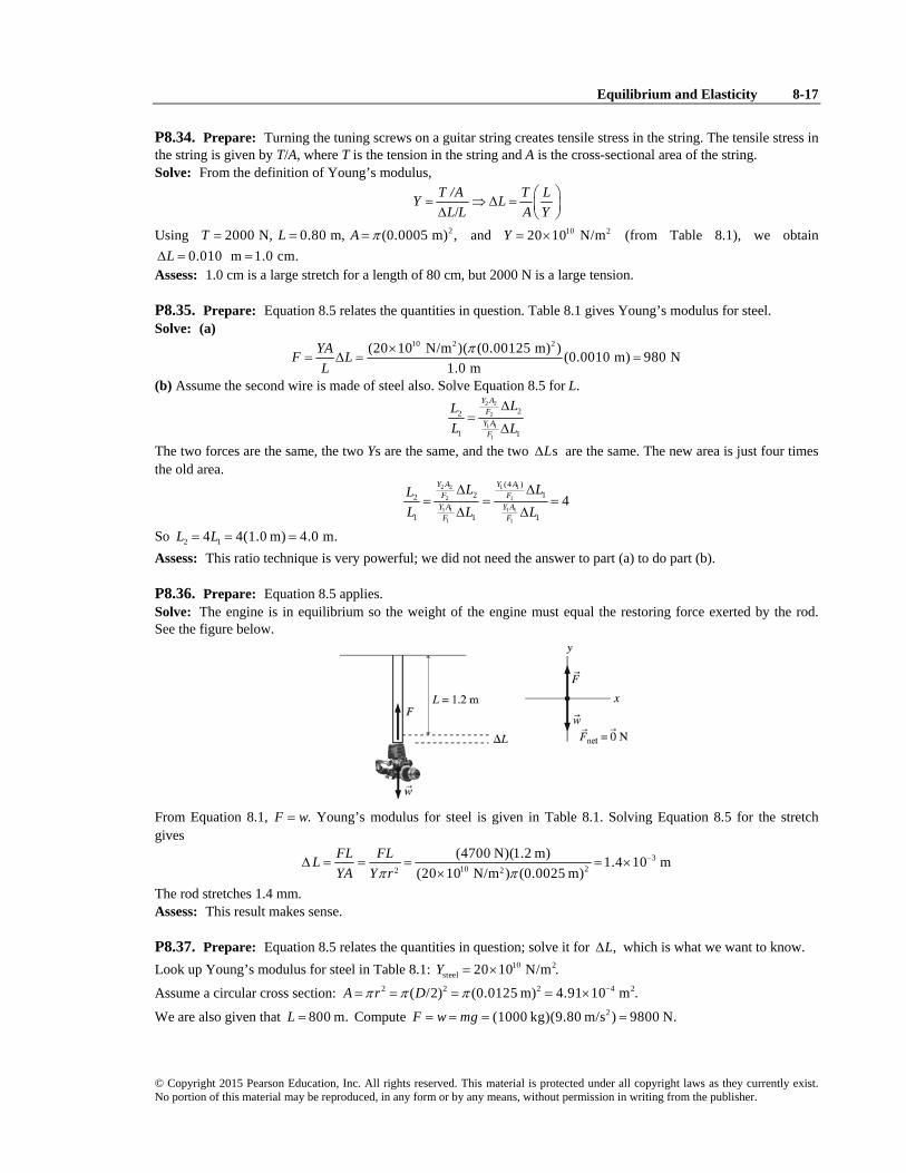
P8.36. Prepare: Equation 8.5 applies. Solve: The engine is in equilibrium so the weight of the engine must equal the restoring force exerted by the rod. See the figure below.
From Equation 8.1, .F w= Young’s modulus for steel is given in Table 8.1. Solving Equation 8.5 for the stretch gives
310 22 2
(4700 N)(1.2 m) 1.4 10 m(20 10 N/m ) (0.0025 m)
FL FLLYA Y rπ π
−Δ = = = = ××
The rod stretches 1.4 mm. Assess: This result makes sense.
P8.37. Prepare: Equation 8.5 relates the quantities in question; solve it for ,LΔ which is what we want to know. Look up Young’s modulus for steel in Table 8.1: 10 2
steel 20 10 N/m .Y = ×
Assume a circular cross section: 2 2 2 4 2( /2) (0.0125 m) 4.91 10 m .A r Dπ π π −= = = = ×
We are also given that 800 m.L = Compute 2(1000 kg)(9.80 m/s ) 9800 N.F w mg= = = =
8-18 Chapter 8
© Copyright 2015 Pearson Education, Inc. All rights reserved. This material is protected under all copyright laws as they currently exist. No portion of this material may be reproduced, in any form or by any means, without permission in writing from the publisher.
Solve:
4 102 2
(800 m)(9800 N) 0.16 m 16 cm(4.91 10 m )(10 10 N/m )
LFLAY −Δ = = = =
× ×
Assess: 16 cm is quite a stretch, but 1000 kg (times g) is quite a bit of weight, and 800 m is quite a long cable, so the answer is reasonable. The design of the shaft would have to take this 16 cm stretch into account. Also check to see that the units work out.
P8.38. Prepare: Solve Equation 8.5 for LΔ . The force is 3 mg. Solve:
2
4 2 10 2
3(80 kg)(9.8 m/s ) (0.52 m)= = = 0.15 mm(5.2 10 m ) (1.6 10 N/m )
F LLAY −Δ
× ×
Assess: That’s a small compression, but bone is strong, and we wouldn’t want it to compress much more than that.
P8.39. Prepare: Equation 8.5 relates the quantities in question; the fractional decrease in length will be / ,L LΔ so rearrange the equation so /L LΔ is isolated. Look up Young’s modulus for Douglas fir in Table 8.1: 10 2
Douglas fir 1 10 N/m .Y = × The total cross section will be three times the area of one leg:
( )22 2 4 2tot 3( ) 3 3 (0.010 m) 9.42 10 m2
DA rπ π π −⎛ ⎞= = = = ×⎜ ⎟⎝ ⎠
Compute 2(75 kg)(9.80 m/s ) 735 N.F w mg= = = = Solve:
54 2 10 2
735 N 7.8 10(9.42 10 m )(1 10 N/m )
L FL AY
−−
Δ= = = ×
× ×
This is a 0.0078% change in length. Assess: We were not given the original length of the stool legs, but regardless of the original length, they decrease in length by only a small percentage—0.0078%—because F isn’t large but A is.
P8.40. Prepare: The load supported by a concrete column creates compressive stress in the concrete column. The weight of the load produces tensile stress given by F/A, where A is the cross-sectional area of the concrete column and F equals the weight of the load. Solve: From the definition of Young’s modulus,
2
2 10 2
/ 200 000 kg 9.8 m/s 3.0 m 1.0 mm/ (0.25 m) 3 10 N/m
F A F LY LL L A Y π
⎛ ⎞⎛ ⎞×⎛ ⎞⎛ ⎞= ⇒ Δ = = =⎜ ⎟⎜ ⎟⎜ ⎟⎜ ⎟Δ ×⎝ ⎠⎝ ⎠ ⎝ ⎠⎝ ⎠
Assess: A compression of 1.0 mm of the concrete column by a load of approximately 200 tons is reasonable.
P8.41. Prepare: The stress is F/A. Solve for F. The maximum stress is the tensile strength; for glass Table 8.2 says the strength is 6 260 10 N/m× . Table 8.1 says for glass 10 27 10 N/m .Y = × Solve: (a)
6 2 6 2 3(tensile strength)(area) (60 10 N/m )( (4.5 10 m) ) 3.8 10 NF π − −= = × × = × So the force required to break the glass fiber is only 3.8 mN. (b) Use the force from part (a) to compute the stretch.
33
6 2 10 2
(10 m)(3.8 10 N) 8.6 10 m( (4.5 10 m) )(7 10 N/m )
LFLAY π
−−
−
×Δ = = = ×
× ×
The data in Table 8.2 was given to only one significant figure, so we report this as 9 mm. Assess: A stretch of just under 1 cm sounds reasonable for a 10-meter fiber.
Equilibrium and Elasticity 8-19
© Copyright 2015 Pearson Education, Inc. All rights reserved. This material is protected under all copyright laws as they currently exist. No portion of this material may be reproduced, in any form or by any means, without permission in writing from the publisher.
P8.42. Prepare: Table 8.3 says for tendon 10 20.15 10 N/m .Y = × Solve: (a)
2
2 2 10 21 m1000 mm
(0.15 m)(8(70 kg)(9.8 m/s )) 5.0 mm(110 mm )( ) (0.15 10 N/m )
LFLAY
Δ = = =×
The tendon will stretch 5.0 mm. (b) The fraction of the tendon’s length is
0.50 cm 0.033 3.3%15 cm
= =
Assess: A 3.3% stretch sounds reasonable.
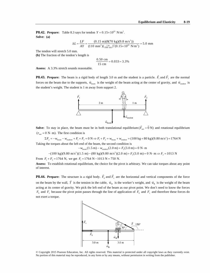
P8.43. Prepare: The beam is a rigid body of length 3.0 m and the student is a particle. 1 2andF F are the normal forces on the beam due to the supports, beamw is the weight of the beam acting at the center of gravity, and studentw is the student’s weight. The student is 1 m away from support 2.
Solve: To stay in place, the beam must be in both translational equilibrium net( 0 N)F = and rotational equilibrium
net( 0 N m).τ = ⋅ The first condition is 2
beam student 1 2 1 2 beam student0 N (100 kg 80 kg)(9.80 m/s ) 1764 NyF w w F F F F w wΣ = − − + + = ⇒ + = + = + = Taking the torques about the left end of the beam, the second condition is
beam student 2(1.5 m) (2.0 m) (3.0 m) 0 N mw w F− − + = ⋅ 2 2
2 2(100 kg)(9.80 m/s )(1.5 m) (80 kg)(9.80 m/s )(2.0 m) (3.0 m) 0 N m 1013 NF F− − + = ⋅ ⇒ = From 1 2 1764 N,F F+ = we get 1 1764 N 1013 N 750 N.F = − = Assess: To establish rotational equilibrium, the choice for the pivot is arbitrary. We can take torques about any point of interest.
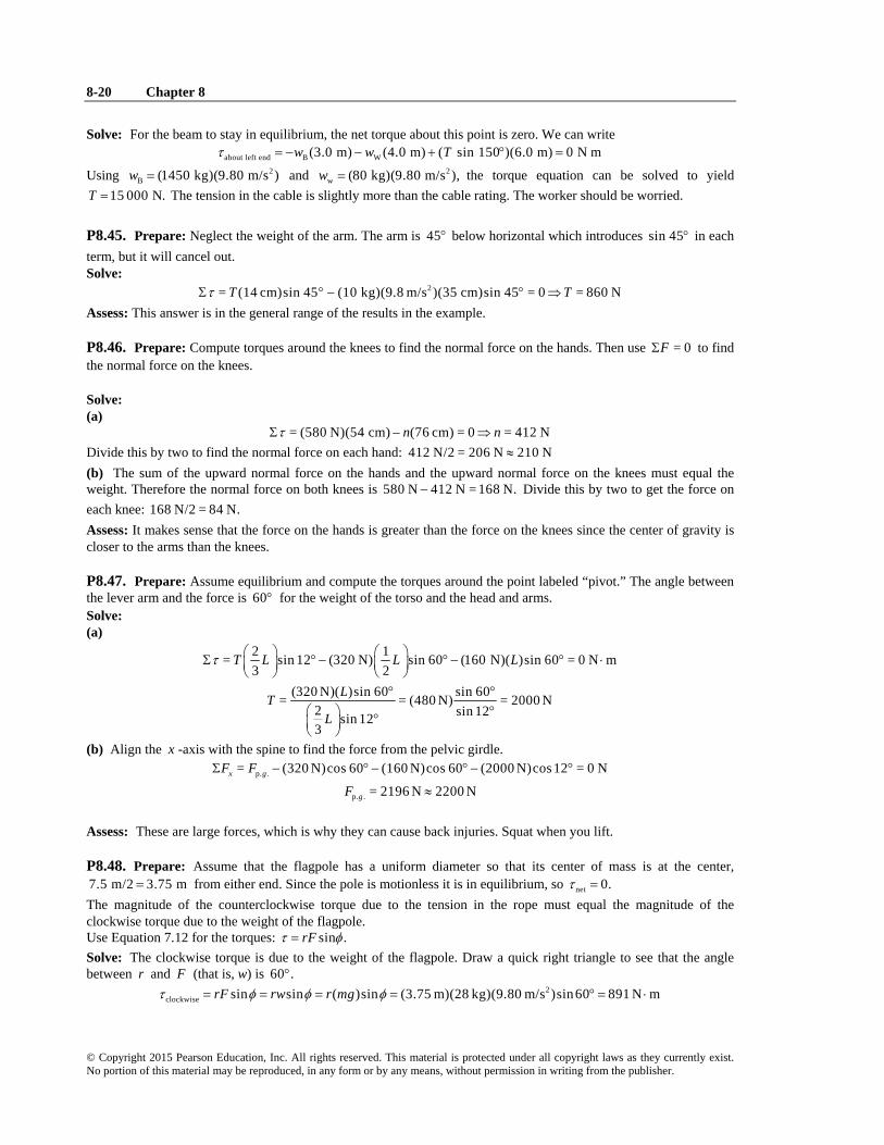
P8.44. Prepare: The structure is a rigid body. h vandF F are the horizontal and vertical components of the force
on the beam by the wall, T is the tension in the cable, Ww is the worker’s weight, and Bw is the weight of the beam acting at its center of gravity. We pick the left end of the beam as our pivot point. We don’t need to know the forces
hF and vF because the pivot point passes through the line of application of hF and vF and therefore these forces do not exert a torque.
8-20 Chapter 8
© Copyright 2015 Pearson Education, Inc. All rights reserved. This material is protected under all copyright laws as they currently exist. No portion of this material may be reproduced, in any form or by any means, without permission in writing from the publisher.
Solve: For the beam to stay in equilibrium, the net torque about this point is zero. We can write about left end B W(3.0 m) (4.0 m) ( sin 150 )(6.0 m) 0 N mw w Tτ = − − + ° =
Using 2B (1450 kg)(9.80 m/s )w = and 2
w (80 kg)(9.80 m/s ),w = the torque equation can be solved to yield 15 000 N.T = The tension in the cable is slightly more than the cable rating. The worker should be worried.
P8.45. Prepare: Neglect the weight of the arm. The arm is 45 below horizontal which introduces sin 45 in each term, but it will cancel out. Solve:
2= (14 cm)sin 45 (10 kg)(9.8 m/s )(35 cm)sin 45 = 0 = 860 NT TτΣ − ⇒ Assess: This answer is in the general range of the results in the example.
P8.46. Prepare: Compute torques around the knees to find the normal force on the hands. Then use = 0FΣ to find the normal force on the knees.
Solve: (a)
= (580 N)(54 cm) (76 cm) = 0 = 412 Nn nτΣ − ⇒ Divide this by two to find the normal force on each hand: 412 N/2 = 206 N 210 N≈ (b) The sum of the upward normal force on the hands and the upward normal force on the knees must equal the weight. Therefore the normal force on both knees is 580 N 412 N = 168 N.− Divide this by two to get the force on each knee: 168 N/2 = 84 N. Assess: It makes sense that the force on the hands is greater than the force on the knees since the center of gravity is closer to the arms than the knees.
P8.47. Prepare: Assume equilibrium and compute the torques around the point labeled “pivot.” The angle between the lever arm and the force is 60° for the weight of the torso and the head and arms. Solve: (a)
2 1= sin 12 (320 N) sin 60 (160 N)( )sin 60 = 0 N m3 2
T L L Lτ ⎛ ⎞ ⎛ ⎞Σ ° − ° − ° ⋅⎜ ⎟ ⎜ ⎟⎝ ⎠ ⎝ ⎠
(320 N)( )sin 60 sin 60= = (480 N) = 2000 N2 sin 12sin 123
LTL
° °⎛ ⎞ °°⎜ ⎟⎝ ⎠
(b) Align the x -axis with the spine to find the force from the pelvic girdle. p. .= (320 N)cos 60 (160 N)cos 60 (2000 N)cos12 = 0 Nx gF FΣ − ° − ° − °
p. . = 2196 N 2200 NgF ≈
Assess: These are large forces, which is why they can cause back injuries. Squat when you lift.
P8.48. Prepare: Assume that the flagpole has a uniform diameter so that its center of mass is at the center, 7.5 m/2 3.75 m= from either end. Since the pole is motionless it is in equilibrium, so net 0.τ = The magnitude of the counterclockwise torque due to the tension in the rope must equal the magnitude of the clockwise torque due to the weight of the flagpole. Use Equation 7.12 for the torques: sin .rFτ φ= Solve: The clockwise torque is due to the weight of the flagpole. Draw a quick right triangle to see that the angle between r and F (that is, w) is 60 .°
2clockwise sin sin ( )sin (3.75 m)(28 kg)(9.80 m/s )sin60 891 N mrF rw r mgτ φ φ φ= = = = ° = ⋅
Equilibrium and Elasticity 8-21
© Copyright 2015 Pearson Education, Inc. All rights reserved. This material is protected under all copyright laws as they currently exist. No portion of this material may be reproduced, in any form or by any means, without permission in writing from the publisher.
In the counterclockwise direction we want to know the force (tension in the rope), so solve the torque equation for F and put in the previous result for the torque. This time r is the distance from the pivot at the bottom of the pole to where the rope is attached at the top of the pole, or 7.5 m.
rope891 N m 350 N
sin (7.5 m)(sin 20 )F
rτφ
⋅= = =
°
Assess: The man must exert 350 N of force because the angle 20° is so small. One way to increase the angle (and the sine of the angle) is to use a longer rope and stand farther back. This will slightly decrease the needed force. By doing this r is not changed; it is still the length of the pole if the rope is attached to the top of the pole.
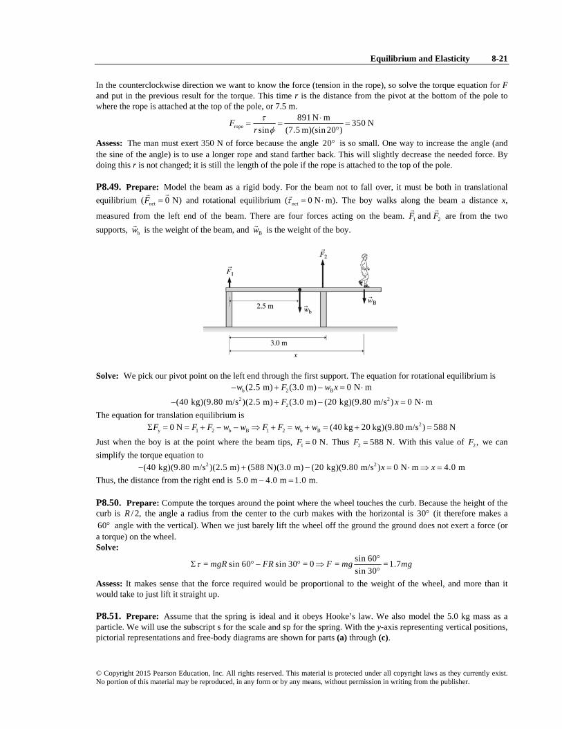
P8.49. Prepare: Model the beam as a rigid body. For the beam not to fall over, it must be both in translational equilibrium net( 0 N)F = and rotational equilibrium net( 0 N m).τ = ⋅ The boy walks along the beam a distance x,
measured from the left end of the beam. There are four forces acting on the beam. 1 2andF F are from the two supports, bw is the weight of the beam, and Bw is the weight of the boy.
Solve: We pick our pivot point on the left end through the first support. The equation for rotational equilibrium is b 2 B(2.5 m) (3.0 m) 0 N mw F w x− + − = ⋅
2 22(40 kg)(9.80 m/s )(2.5 m) (3.0 m) (20 kg)(9.80 m/s ) 0 N mF x− + − = ⋅
The equation for translation equilibrium is 2
y 1 2 b B 1 2 b B0 N (40 kg 20 kg)(9.80 m/s ) 588 NF F F w w F F w wΣ = = + − − ⇒ + = + = + =
Just when the boy is at the point where the beam tips, 1 0 N.F = Thus 2 588 N.F = With this value of 2 ,F we can simplify the torque equation to
2 2(40 kg)(9.80 m/s )(2.5 m) (588 N)(3.0 m) (20 kg)(9.80 m/s ) 0 N m 4.0 mx x− + − = ⋅ ⇒ = Thus, the distance from the right end is 5.0 m 4.0 m 1.0 m.− =
P8.50. Prepare: Compute the torques around the point where the wheel touches the curb. Because the height of the curb is / 2,R the angle a radius from the center to the curb makes with the horizontal is 30° (it therefore makes a 60° angle with the vertical). When we just barely lift the wheel off the ground the ground does not exert a force (or a torque) on the wheel. Solve:
sin 60= sin 60 sin 30 = 0 = = 1.7sin 30
mgR FR F mg mgτ °Σ ° − ° ⇒
°
Assess: It makes sense that the force required would be proportional to the weight of the wheel, and more than it would take to just lift it straight up.
P8.51. Prepare: Assume that the spring is ideal and it obeys Hooke’s law. We also model the 5.0 kg mass as a particle. We will use the subscript s for the scale and sp for the spring. With the y-axis representing vertical positions, pictorial representations and free-body diagrams are shown for parts (a) through (c).
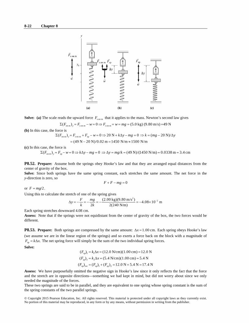
8-22 Chapter 8
© Copyright 2015 Pearson Education, Inc. All rights reserved. This material is protected under all copyright laws as they currently exist. No portion of this material may be reproduced, in any form or by any means, without permission in writing from the publisher.
Solve: (a) The scale reads the upward force s on mF that it applies to the mass. Newton’s second law gives
on m s on m s on m( ) 0 (5.0 kg) (9.80 m/s) 49 NyF F w F w mgΣ = − = ⇒ = = = = (b) In this case, the force is
on m s on m sp( ) 0 20 N 0 ( 20 N)/
(49 N 20 N)/0.02 m 1450 N/m 1500 N/m
Σ = + − = ⇒ + Δ − = ⇒ = − Δ
= − = ≈yF F F w k y mg k mg y
(c) In this case, the force is on m sp( ) 0 0 / (49 N)/(1450 N/m) 0.0338 m 3.4 cmyF F w k y mg y mg kΣ = − = ⇒ Δ − = ⇒ Δ = = = =
P8.52. Prepare: Assume both the springs obey Hooke’s law and that they are arranged equal distances from the center of gravity of the box. Solve: Since both springs have the same spring constant, each stretches the same amount. The net force in the y-direction is zero, so
0F F mg+ − = or /2.F mg= Using this to calculate the stretch of one of the spring gives
22(2.00 kg)(9.80 m/s ) 4.08 10 m
2 2(240 N/m)F mgyk k
−Δ = − = − = − = − ×
Each spring stretches downward 4.08 cm. Assess: Note that if the springs were not equidistant from the center of gravity of the box, the two forces would be different.
P8.53. Prepare: Both springs are compressed by the same amount: 1.00 cm.xΔ = Each spring obeys Hooke’s law (we assume we are in the linear region of the springs) and so exerts a force back on the block with a magnitude of
sp .F k x= Δ The net spring force will simply be the sum of the two individual spring forces. Solve:
sp 1 1
sp 2 2
sp tot sp 1 sp 2
( ) (12.0 N/cm)(1.00 cm) 12.0 N
( ) (5.4 N/cm)(1.00 cm) 5.4 N
( ) ( ) ( ) 12.0 N 5.4 N 17.4 N
F k x
F k x
F F F
= Δ = =
= Δ = =
= + = + =
Assess: We have purposefully omitted the negative sign in Hooke’s law since it only reflects the fact that the force and the stretch are in opposite directions—something we had kept in mind, but did not worry about since we only needed the magnitude of the forces. These two springs are said to be in parallel, and they are equivalent to one spring whose spring constant is the sum of the spring constants of the two parallel springs.
Equilibrium and Elasticity 8-23
© Copyright 2015 Pearson Education, Inc. All rights reserved. This material is protected under all copyright laws as they currently exist. No portion of this material may be reproduced, in any form or by any means, without permission in writing from the publisher.
P8.54. Prepare: When the block is in its equilibrium position, 0.FΣ = So the force exerted to the right by the left spring must be balanced by a force exerted to the left by the right spring. The force exerted by the left spring is
sp 1( ) (10 N/m)(0.020 m) 0.20 N.F = = In part (b) the left spring will exert a force to the left (because it will be stretched to the right); the right force will also exert a force to the left since it will be quite compressed. Remember, the block is no longer in equilibrium, and so we do not expect 0.FΣ = Solve: (a) The force exerted by the right spring must be 0.20 N. This will be produced if
sp2
2
0.20 N 0.010 m 1.0 cm20 N/m
Fx
kΔ = = = =
(b) The spring on the left will be stretched15 cm 2.0 cm 13 cm− = beyond its unstretched length. The force will be toward the left.
sp 1 1 1( ) (10 N/m)(0.13 m) 1.3 NF k x= Δ = = The spring on the right will be compressed15 cm 1.0 cm 16 cm+ = from its uncompressed length. This force will also be toward the left.
sp 2 2 2( ) (20 N/m)(0.16 m) 3.2 NF k x= Δ = = Both forces are to the left so we simply add them up.
net sp 1 sp 2( ) ( ) 1.3 N 3.2 N 4.5 NF F F= + = + = to the left. Assess: In part (b) the right spring exerted a greater force because its k is greater and its length is farther from its unstretched/uncompressed length.
P8.55. Prepare: We will model the student (S) as a particle and the spring as obeying Hooke’s law. The only two forces acting on the student are his weight and the force due to the spring.
Solve: According to Newton’s second law the force on the student is 2 2
on S spring on S spring on S( ) (60 kg)(9.80 m/s 3.0 m/s ) 768 Ny y y yF F w ma F w ma mg maΣ = − = ⇒ = + = + = + =
since spring on S S on spring , 768 N.F F k y k y= = Δ Δ = This means (768 N)/(2500 N/m) 0.307 m 0.31 m.yΔ = = =
8-24 Chapter 8
© Copyright 2015 Pearson Education, Inc. All rights reserved. This material is protected under all copyright laws as they currently exist. No portion of this material may be reproduced, in any form or by any means, without permission in writing from the publisher.
P8.56. Prepare: Assume the spring obeys Hooke’s law. Solve: See the following figure.
At the bottom of the bounce, the child has two forces on him, the force of gravity downwards and the force of the spring upward. There is a net force in the y-direction that causes his upward acceleration. Newton’s second law applied to the child gives
net sp yF F mg k y mg ma= − = Δ − = Solving for the compression of the spring,
2 22
4
(25 kg)(9.8 m/s ) (25 kg)(9.80 m/s ) 2.5 10 m2.0 10 N/m
yma mgy
k−+ +
Δ = = = ××
The spring compresses by 2.5 cm. Assess: This result makes sense. The force on the spring must be enough to overcome gravity and cause an acceleration upward equal to the acceleration of gravity.
P8.57. Prepare: Assume the plank is massless. Compute the torques around the pivot at the left end of the plank.
The cross section area of the rope is 2
5 27.0 mm= = 3.848 10 m .2
A π −⎛ ⎞ ×⎜ ⎟⎝ ⎠
Solve: (a) The maximum tension the rope can support is 7 2 5 2= (6.0 10 N/m )(3.848 10 m ) = 2300 N.T −× ×
(b) Call the distance from the pivot to the machinery at maximum distance x. 2= (3.5 m) (800 kg)(9.8 m/s ) = 0T xτΣ −
2
(2300 N)(3.5 m)= = 1.0 m(800 kg)(9.8 m/s )
x
Assess: 1.0 m isn’t very far along the plank, but the machinery is heavy. We could have moved the machinery farther out if the rope had been thicker.
P8.58. Prepare: Assume gravity is negligible so the only force on the hammer is the tension in the cable.
Solve: (a) The tension in the cable from Newton’s second law for objects in uniform circular motion is 2 2(7.3 kg)(29 m/s)= 5116 N 5100 N
1.2 mmvT
r= = ≈
(b) Young’s modulus for steel is 10 220 10 N/m .×
3 2 10 2
(1.2 m)(5116 N) 4.3 mm(1.5 10 m) (20 10 N/m )
LFLAY π −Δ = = =
× ×
Assess: This seems like a reasonable stretch under strenuous circumstances.
Equilibrium and Elasticity 8-25
© Copyright 2015 Pearson Education, Inc. All rights reserved. This material is protected under all copyright laws as they currently exist. No portion of this material may be reproduced, in any form or by any means, without permission in writing from the publisher.
P8.59. Prepare: Model the disk as a short wide rod. We are asked for the strain—the fractional change in length of the disk. We can solve for /L LΔ from Equation 8.6. Assume that the disk is circular so that the area is 2 2 2 2( /2) (0.020 m) 0.00126 m .A R Dπ π π= = = =
The force is half the weight of the person: 1 1 22 2 (65 kg)(9.80 m/s ) 319 N.F mg= = =
Young's modulus for cartilage is not given in the chapter, but is in the problem: 6 21.0 10 N/m .Y = × Solve: Solve Equation 8.6 for / .L LΔ
10 2 2
319 N 0.000025 0.0025%(1.0 10 N/m )(0.00126 m )
L FL YAΔ
= = = =×
Assess: This means the disk compresses by only a tiny amount. This seems reasonable. Notice that the actual thickness of the disk, given as 0.50 cm, is not needed in the calculation of the fractional compression.
P8.60. Prepare: If you stretch a material until it fails, we call the measured ultimate stress the tensile strength. The tensile strength of tendon is given as 6 2100 10 N/m .× The stress is defined as /F A (see Equation 8.5). So the ultimate stress is 6 2/ 100 10 N/m .F A = ×
We are given that 2 4 2130 mm 1.3 10 m .A −= = × Solve: Solve for F.
6 2 4 62 2(100 10 N/m ) (1.3 10 m )(100 10 N/m ) 13 000 NF A −= × = × × = To answer the question we want to know what fraction of 13 000 N is 3900 N.
3900 N 0.30 30%13 000 N
= =
Assess: We are glad to get an answer in this range. Had we computed a maximum tension less than 3900 N, we would know we did something wrong: 30% of the maximum tension the tendon can handle seems about right.
P8.61. Prepare: We’ll use the data from Example 8.10: original 70 kgm = and 4 2original 4.8 10 m .A −= ×
The femur is not solid cortical bone material; we model it as a tube with an inner diameter and an outer diameter. Look up Young’s modulus for cortical bone in Table 8.1. Solve: (a) Both the inner and outer diameters are increased by a factor of 10; however, the cross-sectional area of the bone material does not increase by a factor of 10. Instead, because 2,A Rπ= the outer cross-sectional area and the inner cross-sectional area (the “hollow” of the tube) both increase by a factor of 100. But this means that the cross-sectional area of the bone material (the difference of the outer and inner areas) also increases by a factor of 100. So the new area is 4 22 2
new 100(4.8 10 m ) 4.8 10 m .A − −= × = × (b) Since volume is a three-dimensional concept, if we increase each linear dimension by a factor of 10 then the volume increases by a factor of 310 1000.= We assume the density of the man is the same as before, so his mass increases by the same factor as the volume: new 1000(70 kg) 70 000 kg.m = = (c) We follow the strategy of Example 8.10. The force compressing the femur is the man’s weight, F mg= =
2(70 000 kg)(9.80 m/s ) 690 000 N.= The resulting stress on the femur is
7 22 2
690 000 N 1.4 10 N/m4.8 10 m
FA −= = ×
×
A stress of 7 21.4 10 N/m× is 14% of the tensile strength of cortical bone given in Table 8.4. Assess: This scaling problem illustrates clearly why animals of different sizes have different proportions. Because the volume scales with the cube of the linear dimensions and the area scales with the square of the linear dimensions then the force in /F A grows more quickly than the cross sectional area does.
P8.62. Prepare: The amount of stretch is given by Equation 8.5: FLLYA
Δ =
8-26 Chapter 8
© Copyright 2015 Pearson Education, Inc. All rights reserved. This material is protected under all copyright laws as they currently exist. No portion of this material may be reproduced, in any form or by any means, without permission in writing from the publisher.
where F is the weight of the spider: 2(0.50 g)(9.80 m/s ) 0.0049 N.w mg= = =
We are given 0.12 mL = and 2 2 2 8 2( /2) (0.15 mm/2) 1.767 10 m .A R Dπ π π −= = = = ×
Look up Young’s modulus for spider silk in Table 8.4: 100.2 10 N/m.Y = × If you stretch a material until it fails, we call the measured ultimate stress the tensile strength. The tensile strength of spider silk is given as 6 21000 10 N/m .× Solve: (a)
510 8 2
(0.0049 N)(0.12 m) 1.7 10 m 0.017 mm(0.2 10 N/m)(1.767 10 m )
FLLYA
−−Δ = = = × =
× ×
(b) The stress is defined as F/A (see Equation 8.5). So the ultimate stress is 6 2/ 1000 10 N/m .F A = × Solve for F. 6 8 62 2 2(1000 10 N/m ) (1.767 10 m )(1000 10 N/m ) 18 NF A −= × = × × =
Assess: The thread of silk can support many times the weight of the spider! As the chapter says, “spider silk has a greater ultimate stress than bone!”
P8.63. Prepare: For equilibrium the sum of the forces must be zero. Solve: For one foot:
2(60 kg)(9.80 m/s )= = 0 = = = 294 N2 2 2y
mg mgF n nΣ − ⇒
So the correct choice is B. Assess: This is half the weight of a typical person.
P8.64. Prepare: Compute the torques around the ankle pivot. Solve:
= (5 cm) (294 N)(15 cm) = 0 = 882 NT TτΣ − ⇒ The correct choice is D. Assess: That’s quite a bit of force, but tendons are strong.
P8.65. Prepare: Use Equation 8.6 and solve for LΔ .
Solve: 4
2 10 2
(882 N)(0.15 m)= = = 8.0 10 m = 0.8 mm(110 mm )(0.15 10 N/m )
FLLAY
−Δ ××
The correct choice is B. Assess: We expect the tendon to stretch a tiny bit, but not much.


