Embed Size (px)
Citation preview

STATE OF TEXAS
PLANS OF PROPOSEDSTATE HIGHWAY IMPROVEMENT
DEPARTMENT OF TRANSPORTATION
TAYLOR COUNTY
FINAL PLANS
DATE CONTRACTOR BEGAN WORK:
DATE WORK WAS COMPLETED:
FINAL CONTRACT COST: $
CONTRACTOR :
LETTING DATE:
DATE WORK WAS ACCEPTED:
STATE COUNTY
JOB
SHEET
DISTRICT
NO.
HIGHWAY NO.
TEXAS
SECTIONCONTROL
DIVISION
TEXAS
FHWA
TAYLOR
$FPN$
0908 00
PROJECT NO.
COUNTY
TAYLOR
101 VA
FI
LE:
pw:\\txdot.project
wiseonline.co
m:
Tx
DO
T2\
Docu
ments\08 -
AB
L\
Design
Projects\090800101\4 -
Design\
Plan
Set\1.
General\
TI
TL
E
SH
EE
T.dgn
DA
TE:
3/17/2020
PE
NT
AB
LE:
ABL
AREA ENGINEER
FINAL ESTIMATE ARE FINAL QUANTITIES.
QUANTITIES SHOWN THEREON AND ON THE
PLANS REFLECT THE WORK DONE AND THE
PLANS AND SPECIFICATIONS. THESE FINAL
THIS PROJECT WAS BUILT ACCORDING TO THE
CERTIFICATION FOR FINAL PLANS
DATE
SEE SHEET 2
INDEX OF SHEETS
SUBMITTED FOR LETTING:
C
ALL RIGHTS RESERVED
BY TEXAS DEPARTMENT OF TRANSPORTATION; 2020
Texas Department of Transportation
R
APPROVED FOR LETTING:
DISTRICT ENGINEER
CARL L. JOHNSON, P.E.
FEDERAL-AID CONSTRUCTION CONTRACTS (FORM FHWA 1273, MAY 1, 2012).
SHALL GOVERN ON THIS PROJECT: REQUIRED CONTRACT PROVISIONS FOR ALL
NOVEMBER 1, 2014 AND SPECIFICATION ITEMS LISTED AND DATED AS FOLLOWS,
SPECIFICATIONS ADOPTED BY THE TEXAS DEPARTMENT OF TRANSPORTATION,
RECOMMENDED FOR LETTING:
DIRECTOR OF T P & D
MICHAEL A. HAITHCOCK, P.E.
EXCEPTIONS:
EQUATIONS:
RAILROAD CROSSINGS:
WIL
LO
W
N 13TH
N 12TH
2.3
ABILENE
AIRPORT
Park
Nelson
Grover
Club
Country
Abilene
Course
Golf
Municipal
Abilene
Cemetery
State School
Abilene
State School
Abilene
Park
Kirby
Fair Grounds
West Texas
Park
Young
Cal
Park
Stevenson
Cem
Mason
Cem
Cedar Hill
University
Christian
Abilene
Park
Hair
Will
2.3 0.5
NO
RT
HE
RN
1.3
1.6
1.6
0.6
1.7
2.4
2.3
PACIFIC
0.8
0.6
0.9
RAILROAD
2.5
0.4
2.1
1.5
2.5
1.2
RAIL
RO
AD
1.7
0.1
3.5
0.9
UP
RR
1.8
2.8
3.8
LAKE
LYTLE
SCOTLAND
Pop 25
ELMDALE
AIRPARK
0.8
AVE
WILSON
S
BLA
CK
TH
OM
AS
GU
Y
PIC
AR
D ST
AFF
OR
D
BO
OK
ER
TW
AS
HIN
GT
ON
CONNALLY
DORIS
BYNUM
PA
LM
OLD
HA
M
LYT
LE
WA
Y
EC
HO
GR
EE
N
RID
GE
W
WILLOWPON
D
SH
ORELI
NE
CA
NT
ER
BU
RY
QUEENKIN
GS
BURY
LA
NC
ELO
T
CAST
LE
LO
NG
BO
TT
OM
MA
NCIP
LES
CH
AU
CE
R
SU
NSET
SA
ND-
PIP
ER
WIL
LOW
WREN
BAIR
D
VIRGIL
CO
CK
RELL
DIAMONDLAKE
CANYON
HA
RW
ELL
AV
E F
HA
RRIS
ON
SC
OT
T
GILL
EV
ER
GR
EE
N
WAS
HIN
GT
ON
GR
EE
NV
AL
LE
Y
RUSWOOD
CHRISWOOD
GA
RY
DE
BO
RA
H
LIS
A
BR
UC
E
CR
EST
HO
UST
ON
URC
H
CA
MP
US C
OU
RTS
ROU
NTR
EE
SP
EA
RS
LOWDEN
HILLVIEWSH
AW
NEE
BYRD
WIL
L
O
KIR
KW
OO
D
VIC
TO
RIA
CLIN
TO
NC
LIN
TO
N SW
EN
SO
N
HIC
KO
RY
PLU
M
SIM
MO
NS
SW
EN
SO
N
BIRCHWOOD
JAMAICA
HUCKLEBERRY
IMPACT
JAMESON
COLLINS
ANSON
SUMMER HOHERTZMCMAHAN
ANTHONY
RHODES
GR
AP
E OR
AN
GE
SIM
MO
NS
BEE
CH
SIM
MO
NS
KIR
KW
OO
D
GR
AH
AM
LIL
LIU
S
CLIN
TO
N
ME
RC
HA
NT
SW
EN
SO
N
CE
DA
R
HIC
KO
RY
OLSE
N
CYP
RESS
PIN
E
WA
LN
UT
KIR
KW
OO
D
GR
AH
AM
PA
RK
AV
E
LIL
LIU
S HO
PE
VIC
TO
RIA
GR
AP
E
AS
H
CE
DA
R
LIN
CO
LN
AV
E
D
AV
E E
CA
MP
US
CO
UR
TS
MO
NR
OE
HA
RR
Y
VIC
TO
RIA
LOWDEN
AMYLYN
VOGEL
UNIVERSITY
DILLINGHAM
ANDERSON
LOWDEN
FORESTER
BECK
-HAM
UNIVERSITY
SANDEFERSANDEFER
N 21ST
N 20TH
N 19THN 19TH
N 18TH
N 17TH
N 16TH
N 16TH
N 16TH
N 16TH
N 16TH
N 15TH
N 15TH
N 23RD
N 22ND
N 21ST
N 21ST
N 2OTH
N 19TH
N 19TH
N 18THN17TH
N 17TH
N 14THN 14TH
N 14TH
N 14TH
14TH
COLLEGE
N 13TH
N 12TH
N 12TH
N 11THN 11TH
N 10TH N 10TH
N 9THN 9TH
HILLCREST
BACON
MA
DIS
ON
GA
RFIE
LD
N 12TH
CH
WAS
HIN
GT
ON
AV
E F
STATE
N 8TH
N 8TH N 8THPARRAMORE
N 7TH N 7TH
N 6TH
N 5TH
N 4TH
N 3RDN 2ND
N 2ND
N 1ST
S 1STS 2ND
S 4TH
S 4THS 5TH
S 5THS 6TH
S 6THS 7TH
S 8TH S 7TH
IDLEWILD
S 10THS 10TH
S 11TH
S 12TH
S 12TH
S 13TH
S 13TH
WASHINGTON
WASHINGTON
S 3RD
KIR
KW
OO
D
GR
AH
AM
VIC
TO
RIA
CLIN
TO
N
ME
RC
HA
NT R
EA
DIN
G
MU
LB
ER
RY
BEE
CH
OR
AN
GE
HIC
KO
RY
CE
DA
RC
YP
RESS
PIN
E
MES
QUIT
E
PLU
MAS
H
CO
TT
ON
WO
OD
BOIS
D'A
RC
N
WA
LN
UT
SA
NT
OS
HIG
HLA
ND
AM
ARIL
LO
ME
AN
DE
R
CHIN
A
ST
EV
EN
SO
N
NELS
ON
ER
ZA
CR
OW
PIEDMONT
MILFORD
VISTA
EASTOVERMEDICAL
TRACY LYNN
SANDY
HAILEY
MINDA
SAMOA
CLARKS
SUMMONERS
OSCAR
ST
ATE
BERRY
GRIG
GS
LYT
LE
AC
RES
OLD
HA
M
ESTATES
NOTTINGHAM
MAP
LE
LYTLE
LYTLE CREEK
BAYLOR
AU
BU
RN
CORNELL
VIN
EVIN
E
PE
AC
H
PE
AC
HP
AL
MP
AL
M
SA
YLES
AM
ARIL
LO
AM
ARIL
LO
ME
AN
DE
R
JA
CKS
ON
JE
AN
ET
TE
PO
PLA
R
BU
TT
ER
NU
T
BEL
MO
NT
JA
CKS
ON
JE
AN
ET
TE
McC
RA
CK
EN
SY
CA
MO
RE
CH
EST
NU
T
OA
K
PE
CA
N
LO
CU
ST
CH
ER
RY
PO
PLA
R
EL
M
COLLEGEDIMMIT
S 14TH
S 15TH S 15TH
S 16THS 16TH
S 16TH
ESTES
WESTWAYS 18TH
S 19TH
S 17TH
S 19TH
S 20TH
OVER
S 21STS 21ST
S 22ND
S 23RD
S 24TH
S 25TH
STADIUM
EDGEMONT
HIG
HLA
ND
S 32ND
BEL
MO
NT
S 27TH
WA
VE
RLY
AM
ARIL
LO
VIN
E
INDUSTRIAL
MAP
LE
McGEE
SY
CA
MO
RE
ST
ADIU
M
AMBLER
INDUSTRIAL
JEFFERIESJEFFERIES
WAGNER
TRUMAN
FRANKLIN
DELANO
CLIN
TO
NVIC
TO
RIA
TEXAS
RUCKER
ROOSEVELT
LO
UIS
RHODES
AUSTIN
CO
TT
ON
WO
OD
AL
MO
ND
N 10TH
N 11TH
MIDWAY
ED
NA
PLA
Y
S 21ST
S 36TH
N 18TH
OLD
AN
SO
N
OAKLAND
LANE
LIN
CO
LN
CA
RV
ER
KE
NW
OO
D
PE
NR
OSE
LA
NC
AST
ER
RE
DW
OO
D
MUSKEN
HO
LLY
WO
OD
T
AN
D
P
HO
SPIT
AL
SQUIRES
HE
ND
ER
SO
N
JU
DG
E ELY
MAP
LE
S 9TH
SAN JACINTO
Cem
City
RAINEY
ELMDALE
Lytle
Creek
Creek
Creek
Cedar
Creek
Lytle
Creek
Rain
y
Creek
Ced
ar
Creek
Rainy
Creek
Creek
Buck
IMPACT
Ced
ar
GATHRIGHTPHEASANT
FALCON
PA
MELA
BRIA
N
HIGH COUNTRY
SU
NFLO
WE
R
DO
VEPLO
YE
R
LILY
DAISY
IVY
SHERRY
MELINDA
IRIS
BO
WIE
N 14TH
TH
N 7TH
N 3RD
N 9TH
N 10TH
HARTFORDA
ND
Y
BROOKH
OLLO
W
TERESA
CIC
LY
BOB O LINK
Cemetery
Park
Memorial
Elmwood
Park
Red Bud
College
McMurry
Rose Park
Oscar
Park
Gill
C W
Park
Cobb
Park
Arthur Sears
Park
Scarborough
CURRY
SH
AR
ON
CURRY
1.5
2.4
1.3
1.8
1.8
2.4
1.4
Camp Park
Vaughn
5.1
RAILROAD
GLEN
DALE
AM
HERST
CREST
WO
OD
WESTWOOD
DENTO
N
HAR
WO
OD
EN
T
NT
3.4
MAIN
HOLIDAY
SANTA FE
SA
NT
ARO
SA
ANN ARBOR
AMBLER
GLE
NH
AV
EN
FO
RR
EST
WESTWOOD
ALA
ME
DA
CR
OC
KET
T
BO
WIE
SA
N JO
SE
LA S
ALLE
JEFFE
RS
ON
PIO
NEE
R
BU
CC
AN
EE
R
WEST
RID
GE
STRATFORD ST
DON JUAN
S 5TH
S 6TH
WEST
RID
GE
OXF
OR
D
HA
WT
HO
RN
E
LE
GG
ET
T
MO
OR
E
ALB
AN
Y
IDLEWILD
AV
EHIG
HLA
ND
BELTON
BURBANK
KIM
BLE
CO
RSIC
AN
A
DO
VE
BLUEQUAIL
BIS
HO
P
KE
NN
YR
EXIE
VIC
KI
SOUTHMOOR
KE
RR
Y
AR
NO
LD
TR
AIL
FAIRMONT
SPRINGBROOK
KINGSTON
FOXMOOR
S 14
TH
WO
OD-
LA
ND
WO
OD
RID
GE
SYL
VA
N
BRO
OK-
HAV
EN
OLD
OR
CH
AR
D
ROB
INWIN
DSO
R
WIN
DR
OC
KW
EN
WO
OD
BIR
CH
SHER
BR
EN
TW
OO
D
POST
BR
EN
TW
OO
D
SEL
MW
OO
DC
RES
C
RE
GE
SY
LVA
N
HO
LLIS
OA
KW
OO
D
VE
GAS
GREENACRES
WYCHW
OOD
IVA
NH
OE
SA
GE
MO
RNIN
G-
HERITAGE
WINTER HAWK
WHITE WING
GREE
NSLOP
ESURREY
SQ
MA
RY
SUSAN
HELENA
STONECRESTRED OAK
ARLINGTON
OAK
HIA
LEA
H
BUTTO N
BUTT ON DERBY
ARROWH
COBBLESTONE
EAD
CONGRESS
CAPITOL
N 1ST
PLA
ZA
PLA
ZA
STATE
CAPITOL
CONGRESS
9N
WIS
HB
ON
E
PIO
NEER
BO
WIE
SA
N JO
SE
LA S
ALLE
JEFFE
RS
ON
PIO
NEE
R
WILSHIRE
CONCORD
LAUREL
RO
AN
OA
K
RIC
HLA
ND
DEL
WO
OD
WEST
WO
OD
JANICE
AZTEC
LAMESA
DURANGO
ENCINO
QUESTA
TAOS
LAGUNA
S 7TH
PUEBLO
SHENANDOAH
CORANDO
RUID
OS
A
CO
RSIC
AN
A
PR
ESIDIO
LE
XIN
GT
ON
SA
XS
ON
TA
NG
LE
WO
OD
RIVER OAKS
WALDEMAR
WALDEMAR
POTOMAC
RICHMOND
FAIRMOUNT
MONTICELLO
BENBROOK
RUSSELL
LE
GG
ET
T
PUEBLO
FAIRMONT
HARTFORD
BA
KE
R
RE
DBIR
D
VAP
OR
LO
UISIA
NA
GR
OU
SE
CH
UC
KE
R
BO
BW
HIT
E
ALAMO
QUAIL RUN
TEXAS
LLANO
BR
EN
DA
SH
ER
E LY
NN
CR
OW
N
TWILIGHT
CLOVER LN
EDGEM OUNT
WO OD
NO
NES
UC
H
RIV
ER
OA
KS
S 20THELMWOOD
OAK
BRIA
R
GR
EE
N
WO
OD
SPANI
SH
SANDEFER
VOGEL
WEST
UNIVERSITY
MO
CKIN
GBIR
D
N 18TH
N 15TH
N 15TH
N 14TH
RO
SE
WO
OD
MA
RS
ALIS
GLE
ND
ALE
YO
RK
TO
WN
BEL AIR
MIN
TE
R
BEE
CH
WO
OD
WEST
VIE
W
BRID
GE
N 12TH
N 11TH
N 10TH
N 9TH
STATE
N 6TH
N 5TH
N 3RD
N 2ND ST
N 1ST S
RED
WO
OD
PE
AK
BEE
CH
WO
OD
WIL
LIS
GLE
NVIE
W
WEST
VIE
W
BRIA
RW
OO
D
WO
OD
LA
WN
PA
RK
AV
E
PA
RK
AV
E
BRIA
RW
OO
D
FA
NNIN
BU
RG
ER
GR
EE
N
SH
ELT
ON
WEST
MO
RELA
ND
S 2ND
RUSSELL
S 3RD
S 4TH
S 5TH
S 6TH
S 7TH
WARD
S 8TH
MELROSE
AVONDALE
S 9TH
S 10TH
S 11TH
ROBERTS
S 12TH
EDGEWOODBICKLEY
LYNNWOOD
RU
BY
MO
RRIS
CA
RL
MIL
LE
R
SE
WELL
PO
RT
LA
ND
LA
RKIN
SU
NSET
SU
NSET
SA
MM
ON
S
MO
CKIN
GBIR
DR
OG
ER
S
ST
OW
E
RO
SS
BA
LLIN
GE
R
WIL
LIS
DA
VIS
GR
OV
E
EL
MW
OO
D
GLE
NW
OO
D
RIV
ER
SID
E
S 13TH
COLLEGE
S 15TH
S 16TH
HUNT
S 19TH
S 18TH
ROSEDALE
HUNTERS
OVER
S 20TH
S 21ST
S 22ND
COLUMBIAS 23RD
MONICA
S 25TH
S 27TH
PARKCREST
GLE
N
GR
EE
NW
OO
D
BA
LLIN
GE
R
WO
OD
AR
D
MA
TA
DO
R
SE
WELL
MA
RS
HA
LL
PO
RT
LA
ND
PO
RT
LA
ND
14TH BA
RR
OW
GR
AN
D
WIL
LIS
S 28TH
BENNETT
EDGEMONTHIGH MEADOWS
S 32ND
HEDGES
S 33RD
S 34TH
S 35TH
COOKE
MOORE
S 38TH
39THS
40THS
S 41ST
LAWRENCE
SA
LIN
AS
SA
NMIG
UEL
SH
EP
AR
D
BA
RR
OW
MA
RS
HA
LL
IVA
NH
OE LN
BUFF
ALO
GAP
GR
AN
D
ERIE
VE
NT
UR
A
IVA
NH
OE
CARNATION
HONEYSUCKLE
MISTLETOE
REBECCAGILMER
DARRELL
WILL
OW
RIMROCK
ROCK
CIR 20
RID
GE
MO
NT
LO
U
PRIMROSE
CA
RRIE
AN
N
BR
UC
E
WESTCHESTER
SA
YLES
CLY
DE
FULTON
RID
GE
WILL
OW
OVER
WOODBRIDGE
S 9TH
Little
Elm
Creek
Elm
Creek
Creek
Elm
Creek
Elm
Creek
Elm
Creek
Creek
SH
ER
MA
N
INWOOD
2.4
2.2
2.5
0.1
1.6
1.8
0.1
BU
RLIN
GT
ON
0.9
HAMBY
Elm
Creek C
edar
2.9
ANSON
ROAD
OLD
1.3
0.1
351
351
2833
20
322
20
1818
36
322
322
36
1750
1750
322
20
83
277
83
277
84
83
84
277
277
83
84
89
3438
3438
3308
2833
1082
600
351
2404
D
B83
D
B83
D
B83
D
B83
D
B83
D
B83 POP 106,654
REGIONAL
R
B20
R
B20
600
GRIF
FIT
H
JU
DG
E ELY
BRIC
K
JAR
MAN
SUMMIT
Office
District
TxDOT
Catcla
w
Creek
University
Simmons
Hardin-
LIMIT
ABIL
EN
E
CIT
Y
LIM
IT
3438
UNION
1.2
322
Park
Wilson
Nelson
TR
EA
DA
WA
Y
R
B20
TR
EA
DA
WA
Y
TREAD
AW
AY
R
B20 UP RR
Elm
Cree
k
Catcla
w
Creek
Buttonwillow
TR
EA
DA
WA
Y
3220.2
20
84
277
1.4
3438
0.3
ABILENE
END PROJECT
L1.
L4.
L2.
L3.
L5.
N
NET LENGTH OF PROJECT= N/A
NET LENGTH OF BRIDGE = N/A
NET LENGTH OF ROADWAY= N/A
N/A
N/A
N/ARECOMMENDED FOR LETTING:
PAUL N. NORMAN, P.E.
AREA ENGINEER
TxDOT PROJECT MANAGER
BRANDON M. VINSON, P.E.
PROPOSED NBI# = N/A
EXISTING NBI# = N/A
FUNCTIONAL CLASS = N/A
PROJECTED A.D.T. = N/A
CURRENT A.D.T. = N/A
DESIGN SPEED = N/A 1
US 83/84, ETC.
LIMITS: VARIOUS LOCATIONS IN ABILENE
FOR THE CONSTRUCTION OF: LANDSCAPE & SCENIC ENHANCEMENT
CONSISTING OF: LANDSCAPE DEVELOPMENT
PROJECT NO. $FPN$
CONCURENCE:
ABILENE CITY MANAGER
ROBERT HANNA

DA
TE:
FI
LE:
4:12:34
PM
3/17/2020
pw:\\txdot.project
wiseonline.co
m:
Tx
DO
T2\
Docu
ments\08 -
AB
L\
Design
Projects\090800101\4 -
Design\
Plan
Set\1.
General\I
ND
EX
OF
SH
EE
TS.dgn
COUNTY
JOB
HIGHWAY NO.
TEXAS
DISTRICT SECTIONCONTROL
TAYLOR
0908 00 101
PROJECT NO.
6
ABL
DIVISION
FHWA
STATE SHEET NO.
VASEE TITLE SHEET
C
Texas Department of Transportation
2020 R
THIS DOCUMENT IS RELEASED
FOR THE PURPOSE OF PRELIMINARY
REVIEW UNDER THE AUTHORITY OF
BRANDON M. VINSON, P.E. 130093
IT IS NOT TO BE USED FOR BIDDING,
CONSTRUCTION, OR PERMITTING PURPOSES.
DATE: 3/17/2020
SHEET 1 OF 1
INDEX OF SHEETS
2
GENERAL
1 TITLE SHEET
2 INDEX OF SHEETS
3 TYPICAL SECTION
4-7 GENERAL NOTES
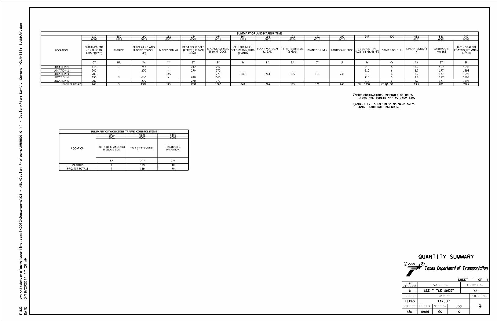
8 ESTIMATE & QUANTITY
9 QUANTITY SUMMARY
TRAFFIC CONTROL PLAN STANDARDS
# 10-21 BC (1)-03 THRU BC (12)-03
# 22 TCP(2-1)-18
# 23 TCP(3-1)-13
ROADWAY DETAILS
24 PAVER PATTERNS DETAIL
25 PLAQUE DETAILS
26 LOCATION 1 MAP
27 LOCATION 1 LAYOUT
28-29 LOCATION 1 PAVER DETAIL
30 LOCATION 2 MAP
31 LOCATION 2 LAYOUT
32-33 LOCATION 2 PAVER DETAIL
34 LOCATION 3 MAP
35 LOCATION 3 LAYOUT
36-37 LOCATION 3 PAVER DETAIL
38 PLANTING PLAN
39 LANDSCAPE DETAILS & SPECIFICATIONS
40 LOCATION 4 MAP
41 LOCATION 4 LAYOUT
42-43 LOCATION 4 PAVER DETAIL
44 LOCATION 5 MAP
45 LOCATION 5 LAYOUT
ENVIRONMENTAL ISSUES
46 SW3P DETAILS
47-48 STORMWATER POLLUTION PREVENTION PLAN (SW3P)
49 ENVIRONMENTAL PERMITS, ISSUES AND COMMITMENTS

CONCRETE PAVER
6" CALICHE BASE
SECTION A-A
A
A
TOPSOIL
EXISTING GROUND
4'
EXISTING GROUND
THIS DOCUMENT IS RELEASED
FOR THE PURPOSE OF PRELIMINARY
REVIEW UNDER THE AUTHORITY OF
BRANDON M. VINSON, P.E. 130093
IT IS NOT TO BE USED FOR BIDDING,
CONSTRUCTION, OR PERMITTING PURPOSES.
DATE: 3/17/2020
6:1
DA
TE:
FI
LE:
4:12:40
PM
3/17/2020
pw:\\txdot.project
wiseonline.co
m:
Tx
DO
T2\
Docu
ments\08 -
AB
L\
Design
Projects\090800101\4 -
Design\
Plan
Set\1.
General\
TY
PI
CA
L
SE
CTI
ON.dgn
COUNTY
JOB
HIGHWAY NO.
TEXAS
DISTRICT SECTIONCONTROL
TAYLOR
0908 00 101
PROJECT NO.
6
ABL
DIVISION
FHWA
STATE SHEET NO.
3
VA
TYPICAL SECTION
NOT TO SCALE SHEET 1 OF 1
SEE TITLE SHEET
C
Texas Department of Transportation
2020 R
45' PAVER FACE
A
A
45' PAVER FACE
(LOCATIONS 2,3 & 5)SECTION THROUGH EMBANKMENT AT HIGHEST POINT
(LOCATIONS 1 & 4)SECTION THROUGH EMBANKMENT AT HIGHEST POINT
18"
EXISTING SOIL OR EMBANKMENT
EXISTING GROUND10' AT LOCATION 1
EDGE RING (4")CONCRETE RIPRAP
6"
EXISTING GROUND
TIE TO
30' AT LOCATION 4
(PAID FOR AS BLADING)
LOCATION 4
REGRADE ] AT
4" TOPSOIL
RIPRAP RING4" CONCRETE
RIPRAP RING4" CONCRETE
RIPRAP RING4" CONCRETE
RIPRAP RING4" CONCRETE
PLACE 4" OF TOPSOIL ACROSS ALL EMBANKMENT AREAS.
NOTE: TIE SLOPES IN EMBANKMENT AREAS SHALL BE 6:1 OR FLATTER.
EXISTING GROUND
TIE TO
18"6"
1/8" TYP.
& MAX
BACKFILL(BEDDING)1 1/4" COMPACTED SAND

pw:\\txdot.project
wiseonline.co
m:
TX
DO
T2\
Docu
ments\08 -
AB
L\
Design
Projects\090800101\4 -
Design\
Plan
Set\1.
General\
GE
NE
RA
L
NO
TE
S.dgn
3/18/2020
10:33:19
AM
JOB HIGHWAY
SHEET NO.COUNTY
CONT SECT
DIST
ransportationDepartment ofT T exas GENERAL NOTES ABL
CR
4
101000908 VA
TAYLOR
2020

pw:\\txdot.project
wiseonline.co
m:
TX
DO
T2\
Docu
ments\08 -
AB
L\
Design
Projects\090800101\4 -
Design\
Plan
Set\1.
General\
GE
NE
RA
L
NO
TE
S.dgn
3/18/2020
10:33:29
AM
JOB HIGHWAY
SHEET NO.COUNTY
CONT SECT
DIST
GENERAL NOTES ransportationDepartment ofT T exas
CR
ABL 5
101000908 VA
TAYLOR
2020

pw:\\txdot.project
wiseonline.co
m:
TX
DO
T2\
Docu
ments\08 -
AB
L\
Design
Projects\090800101\4 -
Design\
Plan
Set\1.
General\
GE
NE
RA
L
NO
TE
S.dgn
3/18/2020
10:33:38
AM
JOB HIGHWAY
SHEET NO.COUNTY
CONT SECT
DIST
GENERAL NOTES ransportationDepartment ofT T exas
CR
ABL 6
101000908 VA
TAYLOR
2020

pw:\\txdot.project
wiseonline.co
m:
TX
DO
T2\
Docu
ments\08 -
AB
L\
Design
Projects\090800101\4 -
Design\
Plan
Set\1.
General\
GE
NE
RA
L
NO
TE
S.dgn
3/18/2020
10:33:47
AM
JOB HIGHWAY
SHEET NO.COUNTY
CONT SECT
DIST
GENERAL NOTES ransportationDepartment ofT T exas
CR
ABL 7
101000908 VA
TAYLOR
2020


DN: CK: DW: CK:FILE:
0908 00 101
TAYLOR
JOB
COUNTY
SECT
DIST
REVISIONS
TxDOT TxDOT TxDOT TxDOT
ABL
HIGHWAY
VA
SHEET NO.
C TxDOT
of this standard to other for
mats or for incorrect results or da
mages resulting fro
m its use.
kind is
made by
Tx
DO
T for any purpose
whatsoever.
Tx
DO
T assu
mes no responsibility for the conversion
The use of this standard is governed by the "
Texas
Engineering
Practice
Act".
No
warranty of any
DI
SC
LAI
ME
R:
CONTNovember 2002
FI
LE:
DA
TE:
pw:\\txdot.project
wiseonline.co
m:
Tx
DO
T2\
Docu
ments\08 -
AB
L\
Design
Projects\090800101\4 -
Design\
Plan
Set\2.
TC
P\
BC(1-12)-14.dgn
3/17/2020
4:13:55
PM
95
SHEET 1 OF 12
AND REQUIREMENTS
GENERAL NOTES
BARRICADE AND CONSTRUCTION
4-03
9-07
5-10
7-13
StandardDivision
OperationsTraffic
BC(1)-14
8-14
bc-14.dgn
http://www.txdot.gov
THE DOCUMENTS BELOW CAN BE FOUND ON-LINE AT
COMPLIANT WORK ZONE TRAFFIC CONTROL DEVICES LIST (CWZTCD)
TEXAS MANUAL ON UNIFORM TRAFFIC CONTROL DEVICES (TMUTCD)
STANDARD HIGHWAY SIGN DESIGNS FOR TEXAS (SHSD)
TRAFFIC ENGINEERING STANDARD SHEETS
MATERIAL PRODUCER LIST (MPL)
ROADWAY DESIGN MANUAL - SEE "MANUALS (ONLINE MANUALS)"
DEPARTMENTAL MATERIAL SPECIFICATIONS (DMS)
Phone (512) 416-3118
Traffic Operations Division - TE
Texas Department of Transportation
below or by contacting:
and their sources and may be found on-line at the web address given
Traffic Control Devices List" (CWZTCD) describes pre-qualified products
Only pre-qualified products shall be used. The "Compliant Work Zone
BARRICADE AND CONSTRUCTION (BC) STANDARD SHEETS GENERAL NOTES:
or as approved by the Engineer.
right-of-way line as possible, or located behind a barrier or guardrail,
must be parked away from travel lanes. They should be as close to the
13. Inactive equipment and work vehicles, including workers' private vehicles
devices.
12. The Engineer has the final decision on the location of all traffic control
exists.
be in place only while work is actually in progress or a definite need
11. Except for devices required by Note 10, traffic control devices should
shall be erected at or near the CSJ limits.
strips. The BEGIN ROAD WORK NEXT X MILES, CONTRACTOR and END ROAD WORK signs
solely of mobile operation work, such as striping or milling edgeline rumble
the TRAFFIC FINES DOUBLE sign will not be required on projects consisting
sign with plaque shall be erected in advance of the CSJ limits. However,
TEXT LATER (see Sign Detail G20-10T) and the WORK ZONE TRAFFIC FINES DOUBLE
10. As shown on BC(2), the OBEY WARNING SIGNS STATE LAW sign, STAY ALERT TALK OR
appropriate traffic control devices to be used.
BC sheets are examples. As necessary, the Engineer will determine the most
9. The temporary traffic control devices shown in the illustrations of the
provide a detail to the Contractor before the sign is manufactured.
not shown in this manual shall be shown in the plans or the Engineer shall
"Standard Highway Sign Designs for Texas," latest edition. Sign details
8. All signs shall be constructed in accordance with the details found in the
justify the signing.
divided highways where median width will permit and traffic volumes
7. The Engineer may require duplicate warning signs on the median side of
revised to show appropriate work zone distance.
directed by the Engineer. The BEGIN ROAD WORK NEXT X MILES sign shall be
necessary warning signs as shown on these sheets, the TCP sheets or as
adjacent project is completed first, the Contractor shall erect the
redundant and the work areas appear continuous to the motorists. If the
FINES DOUBLE, and other advance warning signs if the signing would be
6. When projects abut, the Engineer(s) may omit the END ROAD WORK, TRAFFIC
Design Manual" or engineering judgment.
"A Policy on Geometric Design of Highways and Streets," the TxDOT "Roadway
Association of State Highway and Transportation Officials (AASHTO),
applicable design criteria contained in manuals such as the American
5. Geometric design of lane shifts and detours should, when possible, meet the
the approximate location of any device without the approval of the Engineer.
control devices as shown in the plans. The Contractor may not move or change
4. The Contractor is responsible for installing and maintaining the traffic
sign and seal Contractor proposed changes.
by a licensed professional engineer for approval. The Engineer may develop,
3. The Contractor may propose changes to the TCP that are signed and sealed
responsibility of the Engineer.
2. The development and design of the Traffic Control Plan (TCP)is the
shown in the "Texas Manual on Uniform Traffic Control Devices" (TMUTCD).
The information contained in these sheets meet or exceed the requirements
devices, construction pavement markings, and typical work zone signs.
to show typical examples for placement of temporary traffic control
1. The Barricade and Construction Standard Sheets (BC sheets) are intended
WORKER SAFETY APPAREL NOTES:
considered for high traffic volume work areas or night time work.
performance for Class 2 or 3 risk exposure. Class 3 garments should be
Apparel," or equivalent revisions, and labeled as ANSI 107-2004 standard
the requirements of ISEA "American National Standard for High-Visibility
within the right-of-way shall wear high-visibility safety apparel meeting
1. Workers on foot who are exposed to traffic or to construction equipment
3.0" Radius, 1.25" Border, 0.75" Indent, Black on Yellow;
3.0" Radius, 1.25" Border, 0.75" Indent, Black on Orange;
.75"
1.5"
2"
2"
AND SYMBOL
BORDER
LEGEND,
BLACK
R=1.1"
.94
.94
.94
.94
.41
.42
.31" 1"
.67" .67"
1" .31"
9"
R=.44"
R=.79"
R=.13"
.31"
.31"
14"
.31"
1.14"
1.14"
R=.75"
2.57"
2.88"
1.17"
5.55"
17.5"
6.38"
1.68"1.68" 1.68"
8.38"
4.9" 19.7" 6" 24.5" 4.9"
3.25"
6"
D
12"
48"
4"
1.25"
3.5"
20"
36"
3.5"
5"
C
20" 20" 20"
3.5" 12" 2.8" 6.3"2.8" 11.7" 2.8" 14.6"3.5"
60"
1.25"
SIGN DETAIL (G20-10T)
5".
41
[STAY ALERT] Font: D
[TALK OR TEXT LATER] Font: C specified length;
WHITE
BLACK
WHITE
BACKGROUND
YELLOW
FLUORESCENT
COLORS:
LEGEND
BORDER AND
BLACK
BACKGROUND
FLUORESCENT
ORANGE
10

DN: CK: DW: CK:FILE:
0908 00 101
TAYLOR
JOB
COUNTY
SECT
DIST
REVISIONS
TxDOT TxDOT TxDOT
ABL
HIGHWAY
VA
SHEET NO.
C TxDOT
of this standard to other for
mats or for incorrect results or da
mages resulting fro
m its use.
kind is
made by
Tx
DO
T for any purpose
whatsoever.
Tx
DO
T assu
mes no responsibility for the conversion
The use of this standard is governed by the "
Texas
Engineering
Practice
Act".
No
warranty of any
DI
SC
LAI
ME
R:
CONT
bc-14.dgn
November 2002
FI
LE:
DA
TE:
pw:\\txdot.project
wiseonline.co
m:
Tx
DO
T2\
Docu
ments\08 -
AB
L\
Design
Projects\090800101\4 -
Design\
Plan
Set\2.
TC
P\
BC(1-12)-14.dgn
3/17/2020
4:13:57
PM
96
SHEET 2 OF 12
R11-2
ROAD
CLOSED
XX
ROAD
WORK
AHEAD
END
ROAD WORK
END
ROAD WORK
CW20-1D
CW1-6
ROAD
WORK
AHEAD
CW20-1D
NAME
ADDRESS
CITY
STATE
CONTRACTOR
ROAD WORKNEXT X MILES
BEGIN
ROAD
WORK
AHEAD
ROAD
WORK
AHEAD
PR
OJ
EC
T
1 Block - City
1 Block - City
ROAD WORK
NEXT X MILESROAD WORK
END
ROAD WORK
NEXT X MILES
PR
OJ
EC
T
CROSSROAD
*
X
X
X
X
ROAD
WORK
AHEAD
END
ROAD WORK
END
ROAD WORKCW20-1D
NAME
ADDRESS
CITY
STATE
CONTRACTOR
WORK
ZONE
TRAFFIC
FINES
DOUBLEWHEN
WORKERS
ARE PRESENT
*
*
ROAD WORK
BEGIN
T-INTERSECTION
ROAD
WORK
AHEAD
CW20-1D
CW20-1D
CW20-1D
3X
3X
XX
ROAD WORK
NEXT X MILES
ROAD WORK
NEXT X MILES
NEXT X MILES
INTERSECTED
ROADWAY 1000'-1500' - Hwy
1000'-1500' - Hwy
CSJ Limit
CSJ Limit
XXXXX
XXXXX
*
1,5,6
X
X
TYPICAL LOCATION OF CROSSROAD SIGNS
X
X
WORK
ZONE
TRAFFIC
FINES
DOUBLEWHEN
WORKERS
ARE PRESENT
WORK
ZONE
TRAFFIC
FINES
DOUBLEWHEN
WORKERS
ARE PRESENT
R20-5T
G20-5T
G20-5T
CW1-4R
WORK AREAS IN MULTIPLE LOCATIONS WITHIN CSJ LIMITSSAMPLE LAYOUT OF SIGNING FOR WORK BEGINNING AT THE CSJ LIMITS
**
**
**
**
**
****
**
**
SAMPLE LAYOUT OF SIGNING FOR WORK BEGINNING DOWNSTREAM OF THE CSJ LIMITS
CW1-4L
**
CW20-1E
WORK
ROADG20-5T
/ MILE1
2
NEXT X MILES
*
*
TYPICAL CONSTRUCTION WARNING SIGN SIZE AND SPACING
30
MPH
35
40
45
50
55
60
320
400
500
600
Posted
Speed
Sign
Spacing
(Apprx.)
2
65 700
70 800
3
**
2
2
2
"X"
Feet
120
160
240
75 900 2
80 1000 2
SPACINGSIZE
4
9-07
DevicesChannelizing
DevicesChannelizing
min.
80'
AREAWORK
Limit
CSJ
1 and 4)
see Note
(Optional
1 and 4)
see Note
(Optional
G20-2
G20-1aT
G20-1aT
NEXT X MILES
G20-2
CW13-1P
SPACEWORK
CW13-1PMPH
MPH
G20-2
SPACEWORK
Channelizing Devices
LEGEND
Sign
Type 3 Barricade
spacing requirements.
TMUTCD for sign
Spacing chart or the
Warning Sign Size and
See Typical Construction
G20-1bTRG20-1bTL
R20-5T
R20-5aTPG20-6T
G20-2
R20-5aTP
R20-5T
G20-5aPG20-5aP
G20-2
G20-6T
channelizing devices
Type 3 Barricade or
devices
channelizing
Barricade or
Type 3
G20-6T
GENERAL NOTES
or Series
Number
Sign
Freeway
Expressway/
Road
Conventional
CW20
CW21
CW22 48" x 48" 48" x 48"
CW23
CW25
CW1, CW2,
CW7, CW8, 36" x 36" 48" x 48"
CW9, CW11,
CW14
CW3, CW4,
CW5, CW6, 48" x 48" 48" x 48"
CW8-3,
CW10, CW12
CSJ LIMITS AT T-INTERSECTION
R20-3T
**
TxDOT
G20-5aP
R20-5aTP
7-13
StandardDivision
OperationsTraffic
X
channelizing devices.
within the project limits. See the applicable TCP sheets for exact location and spacing of signs and
"ROAD WORK AHEAD"(CW20-1D)signs are placed in advance of these work areas to remind drivers they are still
When extended distances occur between minimal work spaces, the Engineer/Inspector should ensure additional
(G20-1bTR)" signs shall be replaced by the detour signing called for in the plans.
The "ROAD WORK NEXT X MILES" left arrow(G20-1bTL) and "ROAD WORK NEXT X MILES" right arrow
NAME"(G20-6T) sign behind the Type 3 Barricades for the road closure (see BC(10) also).
2. If construction closes the road at a T-intersection the Contractor shall place the "CONTRACTOR
being performed at or near an intersection.
such as a flagger and accompanying signs, or other signs, that should be used when work is
1. The Engineer will determine the types and location of any additional traffic control devices,
PROJECT LIMIT
BARRICADE AND CONSTRUCTION
WARNING
SIGNS
STATE LAW
OBEY
**R20-3T*
WARNING
SIGNS
STATE LAW
OBEY
WORK
ZONE
TRAFFIC
FINES
DOUBLEWHEN
WORKERS
ARE PRESENT
BEGIN**G20-9TP
**R20-5T
**R20-5aTP
the plans or as determined by the Engineer/Inspector, shall be in place.
6. When work occurs in the intersection area, appropriate traffic control devices, as shown elsewhere in
5. Additional traffic control devices may be shown elsewhere in the plans for higher volume crossroads.
will determine whether a roadway is considered high volume.
motorists of the length of construction in either direction from the intersection. The Engineer
4. The "ROAD WORK NEXT X MILES"(G20-1aT)sign shall be required at high volume crossroads to advise
Zone Standard Sheets.
location and spacing of any sign not shown on the BC sheets, Traffic Control Plan sheets or the Work
be considered part of the minimum requirements. The Engineer/Inspector will determine the proper
AHEAD, LOOSE GRAVEL, or other appropriate signs. When additional signs are required, these signs will
3. Based on existing field conditions, the Engineer/Inspector may require additional signs such as FLAGGER
in the plans.
crossroads. The Engineer will determine whether a road is low volume. This information shall be shown
Texas" manual for sign details. The Engineer may omit the advance warning signs on low volume
"Typical Construction Warning Sign Size and Spacing"). See the "Standard Highway Sign Designs for
with the reduced size 36" x 18" "END ROAD WORK"(G20-2) sign on low volume crossroads (see Note 4 under
2. The Engineer may use the reduced size 36" x 36" ROAD WORK AHEAD (CW20-1D) sign mounted back to back
(G20-2) "END ROAD WORK" sign, unless noted otherwise in plans.
1. The typical minimum signing on a crossroad approach should be a "ROAD WORK AHEAD" (CW20-1D)sign and a
SPEED
LIMIT
XX
X
*
location
with sign
coordinate
line should
NO-PASSING
Beginning of SPEED
LIMIT
XX*
R2-1
R2-1
BC(2)-14
8-14
R2-1
SPEED
LIMIT
XX**
X
G20-10T
XX
CW1-4L
MPHCW13-1PNAME
ADDRESS
CITY
STATE
CONTRACTOR
ROAD WORKNEXT X MILES
BEGIN
*
**
*
NOTES
* the end of the work zone.
Contractor will install a regulatory speed limit sign at
Control Plan.
and other signs or devices as called for on the Traffic
Area for placement of "ROAD WORK AHEAD" (CW20-1D)sign
consisting solely of mobile operations work.
FINES DOUBLE signs will not be required on projects
Required CSJ Limit signing. See Note 10 on BC(1). TRAFFIC
if workers are present.
lying outside the CSJ Limits where traffic fines may double
motorist of entering or leaving a part of the work zone
signs are required outside the CSJ Limits. They inform the
shall be used as shown on the sample layout when advance
The "BEGIN WORK ZONE"(G20-9TP) and "END WORK ZONE" (G20-2bT)
No decimals shall be used.
to the nearest whole mile with the approval of the Engineer.
This distance shall replace the "X" and shall be rounded
WORK NEXT X MILES"(G20-5T)sign for each specific project.
to be placed on the G20-1 series signs and "BEGIN ROAD
The Contractor shall determine the appropriate distance
DO
NOT
PASS
appropriate) (as R4-1
sizes.
Sign Designs for Texas" manual for complete list of available sign design
6. See sign size listing in "TMUTCD", Sign Appendix or the "Standard Highway
5. Only diamond shaped warning sign sizes are indicated.
Location of Crossroad Signs".
crossroads at the discretion of the Engineer. See Note 2 under "Typical
4. 36" x 36" "ROAD WORK AHEAD" (CW20-1D)signs may be used on low volume
or more advance warning.
3. Distance between signs should be increased as required to have 1/2 mile
advance warning.
2. Distance between signs should be increased as required to have 1500 feet
1. Special or larger size signs may be used as necessary.
work area and/or distance between each additional sign.
Minimum distance from work area to first Advance Warning sign nearest the
(TMUTCD) typical application diagrams or TCP Standard Sheets.
see Part 6 of the "Texas Manual on Uniform Traffic Control Devices"
For typical sign spacings on divided highways, expressways and freeways,
G20-10T
SPEED
LIMIT
R2-1
XX**
X X
X
**
*G20-2bT
END
WORK ZONE
**
(See note 2 below)
May be mounted on back of "ROAD WORK AHEAD"(CW20-1D) sign with approval of Engineer.
11

DN: CK: DW: CK:FILE:
0908 00 101
TAYLOR
JOB
COUNTY
SECT
DIST
REVISIONS
TxDOT TxDOT TxDOT
ABL
HIGHWAY
VA
SHEET NO.
C TxDOT
of this standard to other for
mats or for incorrect results or da
mages resulting fro
m its use.
kind is
made by
Tx
DO
T for any purpose
whatsoever.
Tx
DO
T assu
mes no responsibility for the conversion
The use of this standard is governed by the "
Texas
Engineering
Practice
Act".
No
warranty of any
DI
SC
LAI
ME
R:
CONT
bc-14.dgn
November 2002
FI
LE:
DA
TE:
pw:\\txdot.project
wiseonline.co
m:
Tx
DO
T2\
Docu
ments\08 -
AB
L\
Design
Projects\090800101\4 -
Design\
Plan
Set\2.
TC
P\
BC(1-12)-14.dgn
3/17/2020
4:13:58
PM
97
SHEET 3 OF 12
TxDOT
9-07
7-13
StandardDivision
OperationsTraffic
WORK ZONE SPEED LIMIT
BARRICADE AND CONSTRUCTION
SPEED
LIMIT
60
SPEED
LIMIT
70
TYPICAL APPLICATION OF WORK ZONE SPEED LIMIT SIGNS
WORK
ZONE
SPEED
LIMIT
60
WORK
ZONEWORK
ZONE
SPEED
LIMIT
70
(750' - 1500') (750' - 1500')
R2-1
R2-1
R2-1R2-1
Reduced speeds should only be posted in the vicinity
of work activity and not throughout the entire project.
LIMIT
SPEED
CW3-5
See General Note 4
60
and approved by the Texas Transportation Commission, or by City Ordinance when within Incorporated City Limits.
Work zone speed limits shall be regulatory, established in accordance with the "Procedures for Establishing Speed Zones,"
or covered during periods when they are not needed.
Regulatory work zone speed signs (R2-1) shall be removed
signing.
additional advance
See BC(2) for
one direction only.
Signing shown for
LIMITS
CSJ
Note 4
See General
LIMIT
SPEED
CW3-5
60
G20-5aP
G20-5aP
SPEED
LIMIT
60
GENERAL NOTES
GUIDANCE FOR USE:
mounting height.
3. Speed zone signs are illustrated for one direction of travel and are normally posted
for each direction of travel.
40 mph and greater 0.2 to 2 miles
35 mph and less 0.2 to 1 mile
5. Regulatory speed limit signs shall have black legend and border on a white reflective
B. Flagger stationed next to sign.
A. Law enforcement.
C. Portable changeable message sign (PCMS).
This type of work zone speed limit should be included on the design of
the traffic control plans when restricted geometrics with a lower design
speed are present in the work zone and modification of the geometrics to
a higher design speed is not feasible.
Work activity may also be defined as a change in the roadway that requires
a reduced speed for motorists to safely negotiate the work area, including:
a) rough road or damaged pavement surface
b) substantial alteration of roadway geometrics (diversions)
c) construction detours
d) grade
e) width
As long as any of these conditions exist, the work zone speed limit signs
SHORT TERM WORK ZONE SPEED LIMITS
the traffic control plans when workers or equipment are not behind concrete
f) other conditions readily apparent to the driver
projects where speed control is of major importance.
E. Speed monitor trailers or signs.
D. Low-power (drone) radar transmitter.
(See Removing or Covering on BC(4)).
Long/Intermediate Term Work Zone Speed Limit signs, when approved as described
above, should be posted and visible to the motorist when work activity is present.
motorists only when work activity is present. When work activity is not
present, signs shall be removed or covered.
Short Term Work Zone Speed Limit signs should be posted and visible to the
background (See "Reflective Sheeting" on BC(4)).
4. Frequency of work zone speed limit signs should be:
8. Techniques that may help reduce traffic speeds include but are not limited to:
2. Regulatory work zone speed limit signs shall be placed on supports at a 7 foot minimum
should remain in place.
1. Regulatory work zone speed limits should be used only for sections of construction
LONG/INTERMEDIATE TERM WORK ZONE SPEED LIMITS
zone reduction see TxDOT form #1204 in the TxDOT e-form system.
conditions and factors impacting allowable regulatory construction speed
10.For more specific guidance concerning the type of work, work zone
Work Zone Speed Limits should only be posted as approved for each project.
9. Speeds shown on details above are for illustration only.
This type of work zone speed limit may be included on the design of
barrier, when work activity is within 10 feet of the traveled way or actually
in the travelled way.
otherwise noted under "REMOVING OR COVERING" on BC(4).
7. Turning signs from view, laying signs over or down will not be allowed, unless as
directly, but shall be considered subsidiary to Item 502.
"WORK ZONE"(G20-5aP) plaque and the "SPEED LIMIT"(R2-1)signs shall not be paid for
6. Fabrication, erection and maintenance of the"ADVANCE SPEED LIMIT"(CW3-5)sign,
Note 4
See General
R2-1
WORK
ZONE
SPEED
LIMIT
60R2-1
signing.
additional advance
See BC(2) for
one direction only.
Signing shown for
G20-5aPG20-5aP
SPEED
LIMIT
70 R2-1
LIMITS
CSJ
BC(3)-14
8-14
12

DN: CK: DW: CK:FILE:
0908 00 101
TAYLOR
JOB
COUNTY
SECT
DIST
REVISIONS
TxDOT TxDOT TxDOT TxDOT
ABL
HIGHWAY
VA
SHEET NO.
C TxDOT
of this standard to other for
mats or for incorrect results or da
mages resulting fro
m its use.
kind is
made by
Tx
DO
T for any purpose
whatsoever.
Tx
DO
T assu
mes no responsibility for the conversion
The use of this standard is governed by the "
Texas
Engineering
Practice
Act".
No
warranty of any
DI
SC
LAI
ME
R:
CONT
bc-14.dgn
November 2002
FI
LE:
DA
TE:
pw:\\txdot.project
wiseonline.co
m:
Tx
DO
T2\
Docu
ments\08 -
AB
L\
Design
Projects\090800101\4 -
Design\
Plan
Set\2.
TC
P\
BC(1-12)-14.dgn
3/17/2020
4:13:59
PM
98
SHEET 4 OF 12
9-07
7-13
StandardDivision
OperationsTraffic
TEMPORARY SIGN NOTES
BARRICADE AND CONSTRUCTION
Curb
XX
Travel lane edge
12' min.
FRONT ELEVATION
SIDE ELEVATION
Travel lane edge
OR
TYPICAL MINIMUM CLEARANCES FOR LONG TERM AND INTERMEDIATE TERM SIGNS
*
*
CONTRACTOR REQUIREMENTS FOR MAINTAINING PERMANENT SIGNS
WITHIN THE PROJECT LIMITS
0'-6'
1. Permanent signs are used to give notice of traffic laws or regulations, call
attention to conditions that are potentially hazardous to traffic operations,
show route designations, destinations, directions, distances, services, points
of interest, and other geographical, recreational, or cultural information.
Drivers proceeding through a work zone need the same, if not better route
guidance as normally installed on a roadway without construction.
2. When permanent regulatory or warning signs conflict with work zone conditions,
3. When existing permanent signs are moved and relocated due to construction
purposes, they shall be visible to motorists at all times.
4. If existing signs are to be relocated on their original supports, they shall be
installed on crashworthy bases as shown on the SMD Standard sheets. The signs
shall meet the required mounting heights shown on the BC Sheets or the SMD
Standards. This work should be paid for under the appropriate pay item for
relocating existing signs.
5. If permanent signs are to be removed and relocated using temporary supports,
the Contractor shall use crashworthy supports as shown on the BC sheets or the
CWZTCD. The signs shall meet the required mounting heights shown on the
BC Sheets or the SMD Standards during construction. This work should be paid
for under the appropriate pay item for relocating existing signs.
6. Any sign or traffic control device that is struck or damaged by the Contractor
or his/her construction equipment shall be replaced as soon as possible by the
Contractor to ensure proper guidance for the motorists. This will be subsidiary
to Item 502.
remove or cover the permanent signs until the permanent sign message matches
the roadway condition.
**
**
ATTACHMENT FOR SIGN SUPPORTS
Wood
STOP/SLOW PADDLES
10" 10"
24"
24"
24"
24"
8"C 8"B
†"
9" 8Š"
R=2"3"
„"+
6.0' min.
Fiber Reinforced Plastic
Wood, metal or
the ground.
SIZE OF SIGNS
SIGN SUBSTRATES
SIGN LETTERS
Hand Signaling Devices in the TMUTCD.
shall only be as specifically described in Section 6E.03
4. Any lights incorporated into the STOP or SLOW paddle faces
length of 6' to the bottom of the sign.
3. STOP/SLOW paddles may be attached to a staff with a minimum
retroreflectorized.
2. When used at night, the STOP/SLOW paddle shall be
as detailed below.
by flaggers. The STOP/SLOW paddle size should be 24" x 24"
1. STOP/SLOW paddles are the primary method to control traffic
curb
from
minimum
2 '
min.
6'
9.0' max.
7.0' min.
9.0' max.
7.0' min.
9.0' max.
7.0' min.
shoulder
Paved
shoulder
Paved
above sign
protrude
shall not
Support
above sign
protrude
shall not
Support
substrate.
back of the sign
1/2 way up the
extend more than
Sign supports shall
Legend & Border - White
Background - Red
Legend & Border - Black
Background - Orange
Supplemental plaques (advisory or distance) should not cover the surface of the parent sign.
When plaques are placed on dual-leg supports, they should be attached to the upright nearest the travel lane.
Objects shall NOT be placed under skids as a means of leveling.
When placing skid supports on unlevel ground, the leg post lengths must be adjusted so the sign appears straight and plumb.
MPH
be allowed.
other means.
by splicing or
extended or repaired
supports shall not be
any means. Wood
joined or spliced by
signs shall not be
support. Multiple
directly to the sign
shall be attached
Each sign
Nails shall NOT
sign supports
substrates to other types of
procedures for attaching sign
manufacturer's recommended
or screws. Use TxDOT's or
will be by bolts and nuts
Attachment to wooden supports
FLAGS ON SIGNS
greater
6' or
of at least the same gauge material.
should be at least 5 times nominal post size, centered on the splice and
the sign substrate, not near the base of the support. Splice insert lengths
above and two below the spice point. Splice must be located entirely behind
height will only be allowed when the splice is made using four bolts, two
Splicing embedded perforated square metal tubing in order to extend post
GENERAL NOTES FOR WORK ZONE SIGNS
1. Contractor shall install and maintain signs in a straight and plumb condition and/or as directed by the Engineer.
2. Wooden sign posts shall be painted white.
3. Barricades shall NOT be used as sign supports.
4. All signs shall be installed in accordance with the plans or as directed by the Engineer. Signs shall be used to regulate, warn, and
guide the traveling public safely through the work zone.
5. The Contractor may furnish either the sign design shown in the plans or in the "Standard Highway Sign Designs for Texas" (SHSD). The
Engineer/Inspector may require the Contractor to furnish other work zone signs that are shown in the TMUTCD but may have been omitted
from the plans. Any variation in the plans shall be documented by written agreement between the Engineer and the Contractor's
Responsible Person. All changes must be documented in writing before being implemented. This can include documenting the changes in
the Inspector's TxDOT diary and having both the Inspector and Contractor initial and date the agreed upon changes.
6. The Contractor shall furnish sign supports listed in the "Compliant Work Zone Traffic Control Device List" (CWZTCD). The Contractor
shall install the sign support in accordance with the manufacturer's recommendations. If there is a question regarding installation
procedures, the Contractor shall furnish the Engineer a copy of the manufacturer's installation recommendations so the Engineer can
verify the correct procedures are being followed.
7. The Contractor is responsible for installing signs on approved supports and replacing signs with damaged or cracked substrates and/or
damaged or marred reflective sheeting as directed by the Engineer/Inspector.
8. Identification markings may be shown only on the back of the sign substrate. The maximum height of letters and/or company logos used
for identification shall be 1 inch.
DURATION OF WORK (as defined by the "Texas Manual on Uniform Traffic Control Devices" Part 6)
1. The types of sign supports, sign mounting height,the size of signs, and the type of sign substrates can vary based on the type of
work being performed. The Engineer is responsible for selecting the appropriate size sign for the type of work being performed. The
Contractor is responsible for ensuring the sign support, sign mounting height and substrate meets manufacturer's recommendations in
regard to crashworthiness and duration of work requirements.
a. Long-term stationary - work that occupies a location more than 3 days.
more than one hour.
c. Short-term stationary - daytime work that occupies a location for more than 1 hour in a single daylight period.
d. Short, duration - work that occupies a location up to 1 hour.
e. Mobile - work that moves continuously or intermittently (stopping for up to approximately 15 minutes.)
SIGN MOUNTING HEIGHT
1. The bottom of Long-term/Intermediate-term signs shall be at least 7 feet, but not more than 9 feet, above the paved surface, except
as shown for supplemental plaques mounted below other signs.
2. The bottom of Short-term/Short Duration signs shall be a minimum of 1 foot above the pavement surface but no more than 2 feet above
3. Long-term/Intermediate-term Signs may be used in lieu of Short-term/Short Duration signing.
appropriate Long-term/Intermediate sign height.
5. Regulatory signs shall be mounted at least 7 feet, but not more than 9 feet, above the paved surface regardless of work duration.
REFLECTIVE SHEETING
1. All signs shall be retroreflective and constructed of sheeting meeting the color and retro-reflectivity requirements of DMS-8300
for rigid signs or DMS-8310 for roll-up signs. The web address for DMS specifications is shown on BC(1).
1. All sign letters and numbers shall be clear, and open rounded type uppercase alphabet letters as approved by the Federal Highway
Administration (FHWA) and as published in the "Standard Highway Sign Design for Texas" manual. Signs, letters and numbers shall be of
first class workmanship in accordance with Department Standards and Specifications.
REMOVING OR COVERING
1. When sign messages may be confusing or do not apply, the signs shall be removed or completely covered.
2. Long-term stationary or intermediate stationary signs installed on square metal tubing may be turned away from traffic 90 degrees when
3. Signs installed on wooden skids shall not be turned at 90 degree angles to the roadway. These signs should be removed or completely
covered when not required.
4. When signs are covered, the material used shall be opaque, such as heavy mil black plastic, or other materials which will cover the
9. The Contractor shall replace damaged wood posts. New or damaged wood sign posts shall not be spliced.
1. The Contractor shall furnish the sign sizes shown on BC (2) unless otherwise shown in the plans or as directed by the Engineer.
intersections where the sign may be seen from approaching traffic.
the sign message is not applicable. This technique may not be used for signs installed in the median of divided highways or near any
1. The Contractor shall ensure the sign substrate is installed in accordance with the manufacturer's recommendations for the type of sign
support that is being used. The CWZTCD lists each substrate that can be used on the different types and models of sign supports.
2. "Mesh" type materials are NOT an approved sign substrate, regardless of the tightness of the weave.
3. All wooden individual sign panels fabricated from 2 or more pieces shall have one or more plywood cleat, 1/2" thick by 6" wide,
fastened to the back of the sign and extending fully across the sign. The cleat shall be attached to the back of the sign using wood
screws that do not penetrate the face of the sign panel. The screws shall be placed on both sides of the splice and spaced at 6"
centers. The Engineer may approve other methods of splicing the sign face.
b. Intermediate-term stationary - work that occupies a location more than one daylight period up to 3 days, or nighttime work lasting
2. White sheeting, meeting the requirements of DMS-8300 Type A, shall be used for signs with a white background.
FL3. Orange sheeting, meeting the requirements of DMS-8300 Type B or Type C , shall be used for rigid signs with orange backgrounds.FL
4. Short-term/Short Duration signs shall be used only during daylight and shall be removed at the end of the workday or raised to
5. Burlap shall NOT be used to cover signs.
SIGN SUPPORT WEIGHTS
6. Duct tape or other adhesive material shall NOT be affixed to a sign face.
1. Where sign supports require the use of weights to keep from turning over,
the use of sandbags with dry, cohesionless sand should be used.
2. The sandbags will be tied shut to keep the sand from spilling and to
maintain a constant weight.
3. Rock, concrete, iron, steel or other solid objects shall not be permitted
for use as sign support weights.
4. Sandbags should weigh a minimum of 35 lbs and a maximum of 50 lbs.
5. Sandbags shall be made of a durable material that tears upon vehicular
6. Rubber ballasts designed for channelizing devices should not be used for
ballast on portable sign supports. Sign supports designed and manufactured
with rubber bases may be used when shown on the CWZTCD list.
7. Sandbags shall only be placed along or laid over the base supports of the
traffic control device and shall not be suspended above ground level or
hung with rope, wire, chains or other fasteners. Sandbags shall be placed
along the length of the skids to weigh down the sign support.
8. Sandbags shall NOT be placed under the skid and shall not be used to level
sign supports placed on slopes.
impact. Rubber (such as tire inner tubes) shall NOT be used.
the sign face.
red-orange in color. Flags shall not be allowed to cover any portion of
shall be 16 inches square or larger and shall be orange or fluorescent
1. Flags may be used to draw attention to warning signs. When used the flag
entire sign face and maintain their opaque properties under automobile headlights at night, without damaging the sign sheeting.
7. Signs and anchor stubs shall be removed and holes backfilled upon completion of work.
BC(4)-14
8-14
13

DN: CK: DW: CK:
0908 00 101
TAYLOR
JOB
COUNTY
SECT
DIST
TxDOT TxDOT TxDOT TxDOT
ABL
HIGHWAY
VA
SHEET NO.
CONT
FI
LE:
DA
TE:
pw:\\txdot.project
wiseonline.co
m:
Tx
DO
T2\
Docu
ments\08 -
AB
L\
Design
Projects\090800101\4 -
Design\
Plan
Set\2.
TC
P\
BC(1-12)-14.dgn
3/17/2020
4:14:01
PM
99
7-13
of this standard to other for
mats or for incorrect results or da
mages resulting fro
m its use.
kind is
made by
Tx
DO
T for any purpose
whatsoever.
Tx
DO
T assu
mes no responsibility for the conversion
The use of this standard is governed by the "
Texas
Engineering
Practice
Act".
No
warranty of any
DI
SC
LAI
ME
R:
30"
40"
27"
36"
24"
2x6
2x4 x 40"
72"
2x6
Front Side
Top
*
*
that can be used for each approved sign support.
See the CWZTCD for the type of sign substrate
NOT be allowed. Posts shall be painted white.
Wood sign posts MUST be one piece. Splicing will
See BC(4) for definition of "Work Duration."
post
wood
4x4
sign face
21 sq. ft. of
Maximum
block
4x4
post
wood
4x4
requirement
height
for sign
See BC(4)
This will be considered subsidiary to Item 502.
foundations shall be removed from the project site.
3. When project is completed, all sign supports and
CWZTCD List.
7 ft. circle, except for specific materials noted on the
2. No more than 2 sign posts shall be placed within a
connection.
lag screws must be used on every joint for final
supports, but 3/8" bolts with nuts or 3/8" x 3 1/2"
1. Nails may be used in the assembly of wooden sign
GENERAL NOTES
Front
*
post
wood
4x4
requirement
height
for sign
See BC(4)
sign face
12 sq. ft. of
Maximum 24"
60"
2x6
2x6
Top
block
4x4
skid
2x6
additional stability.
be increased for
Length of skids may
24" 2x4 brace
4x4 block4x4 block
Side
screws
(min.) lag
or 3/8" x 3 1/2"
3/8" bolts w/nuts
LONG/INTERMEDIATE TERM STATIONARY - PORTABLE SKID MOUNTED SIGN SUPPORTS
SKID MOUNTED WOOD SIGN SUPPORTSPERFORATED SQUARE METAL TUBING
GROUND MOUNTED SIGN SUPPORTS
Two post installations can be used for larger signs.
The maximum sign square footage shall adhere to the manufacturer's recommendation.
Refer to the CWZTCD and the manufacturer's installation procedure for each type sign support.
4" max.
Grou
nd s
urfa
ce
WING CHANNEL
Post
Sign
Post
Base
for embedment.
See the CWZTCD
48"
5'
square tubing
or 1 3/4" x 1 3/4"
with 5/16" holes
1 3/4" galv. round
(DO NOT SPLICE)
12 ga post
1 3/4" x 1 3/4" x 11 foot
CWZTCD LIST. SEE BC(1) FOR WEBSITE LOCATION.
AND SHORT TERM SUPPORTS CAN BE FOUND ON THE
MORE DETAILS OF APPROVED LONG/INTERMEDIATE
Posts
of
Number
MOUNTED SIGN SUPPORTS
WOOD POST SYSTEM FOR GROUND
WEDGE ANCHORS
18"
4"
*
4"
6"
of Traffic
Direction
Dia.(typ)
1 1/2"
17 1/2"
20 1/2"5 BOLT (TYP.)
3/8" X 4-1/2 gr.
3"
telescopes into sleeve
(hole to hole) 12 ga. support
1 3/4 " x 1 3/4 " x 129"
tubing diagonal brace
to hole) 12 ga. square perforated
1 3/4 " x 1 3/4 " x 52" (hole
tubing cross brace
to hole) 12 ga. square perforated
1 3/4 " x 1 3/4 " x 32" (hole
20 1/2"
above pavement
provide 7' height
telescope to
Upright must
5 bolt
3/8 " X 3" gr.
Grou
nd s
urfa
ce
Post
Sign
(Direct Embedment)
OPTION 1
max.
4"
Grou
nd s
urfa
ce
Post
Sign
weak soils.
55" min. in
strong soils,
34" min. in
(Anchor Stub)
OPTION 2
post)
than sign
(1/4" larger
Anchor Stub
desirable
9"max.
4"
Grou
nd s
urfa
ce
Post
Sign
post) x 18"
than sign
(1/2" larger
sleeve
reinforcing
Optional
18"
weak soils.
55" min. in
strong soils,
34" min. in
(Anchor Stub and Reinforcing Sleeve))
OPTION 3
post)
than sign
(1/4" larger
Anchor Stub
desirable
9"
bolted anchorLap-splice/base
minimum
48"
sign only
thinwall plastic
10mm extruded
9 sq. ft. or less-
1/2" plywood is allowed.
the CWZTCD, except 5/8" plywood.
substrate listed in section J.2.d of
16 sq. ft. or less of any rigid sign
OTHER DESIGNS
"Traffic Engineering Standard Sheets" on BC(1)).
if approved by the Engineer. (See web address for
face. They may be set in concrete or in sturdy soils
sign supports for signs up to 10 square feet of sign
on the SMD Standard Sheets may be used as temporary
Both steel and plastic Wedge Anchor Systems as shown
84"
41"
21"
131 1/2 "
4"
sign panel and supports
(2 per support) joining
3/8" x 3" gr. 5 bolt
FILE:
REVISIONS
C TxDOT
bc-14.dgn
November 2002
9-07
36"match sideslope
needed to
pin at angle
weld starts here
weldhere
starts
weld
back fill puddle.
weld, do not
directions. Minimum
going in opposite
opposite sides
Welds to start on
48"
2"
Side View
upright
12 ga.
2" x 2" x
2.5'
60"
3"
SKID MOUNTED PERFORATED SQUARE STEEL TUBING SIGN SUPPORTS
around tubing
Completely welded
8 1/2"
7/16"
32'SINGLE LEG BASE
5'
weld
welded to skid
tubing sleeve
perforated
12 ga. square
(hole to hole)
2" x 2" x 8"
tubing upright
perforated
12 ga. square
(hole to hole)
1 3/4 " x 1 3/4 " x 129"
tubing skid
12 ga. perforated
(hole to hole)
2" x 2" x 59"
StandardDivision
OperationsTraffic
TYPICAL SIGN SUPPORT
BARRICADE AND CONSTRUCTION
SHEET 5 OF 12
BC(5)-14
8-14
14

DN: CK: DW: CK:
0908 00 101
TAYLOR
JOB
COUNTY
SECT
DIST
REVISIONS
ABL
HIGHWAY
VA
SHEET NO.
CONT
bc-14.dgn
November 2002
FI
LE:
DA
TE:
pw:\\txdot.project
wiseonline.co
m:
Tx
DO
T2\
Docu
ments\08 -
AB
L\
Design
Projects\090800101\4 -
Design\
Plan
Set\2.
TC
P\
BC(1-12)-14.dgn
3/17/2020
4:14:03
PM
100
SHEET 6 OF 12
StandardDivision
OperationsTraffic
MESSAGE SIGN (PCMS)
PORTABLE CHANGEABLE
BARRICADE AND CONSTRUCTION
TxDOT TxDOTTxDOT TxDOT FILE:
C TxDOT
9-07
PCMS SIGNS WITHIN THE R.O.W. SHALL BE BEHIND GUARDRAIL OR
CONCRETE BARRIER OR SHALL HAVE A MINIMUM OF FOUR (4)
PLASTIC DRUMS PLACED PERPENDICULAR TO TRAFFIC ON THE
LANES SHIFT in Phase 1 must be used with STAY IN LANE in Phase 2.* *
Roadway
designation # IH-number, US-number, SH-number, FM-number
1. When Full Matrix PCMS signs are used, the character height and legibility/visibility requirements shall be maintained as listed in Note 15 under "PORTABLE
CHANGEABLE MESSAGE SIGNS" above.
shall maintain the legibility/visibility requirement listed above.
for, or replace that sign.
4. A full matrix PCMS may be used to simulate a flashing arrow board provided it meets the visibility, flash rate and dimming requirements on BC(7), for the
same size arrow.
FULL MATRIX PCMS SIGNS
Access Road ACCS RD Major MAJ
Construction
WORDING ALTERNATIVES
1. The words RIGHT, LEFT and ALL can be interchanged as appropriate.
2. Roadway designations IH, US, SH, FM and LP can be interchanged as
appropriate.
3. EAST, WEST, NORTH and SOUTH (or abbreviations E, W, N and S) can
be interchanged as appropriate.
4. Highway names and numbers replaced as appropriate.
5. ROAD, HIGHWAY and FREEWAY can be interchanged as needed.
6. AHEAD may be used instead of distances if necessary.
7. FT and MI, MILE and MILES interchanged as appropriate.
8. AT, BEFORE and PAST interchanged as needed.
9. Distances or AHEAD can be eliminated from the message if a
location phase is used.
3. When symbol signs are represented graphically on the Full Matrix PCMS, they shall only supplement the use of the static sign represented, and shall not substitute
APPLICATION GUIDELINES
1. Only 1 or 2 phases are to be used on a PCMS.
2. The 1st phase (or both) should be selected from the
"Road/Lane/Ramp Closure List" and the "Other Condition List".
3. A 2nd phase can be selected from the "Action to Take/Effect
on Travel, Location, General Warning, or Advance Notice
Phase Lists".
4. A Location Phase is necessary only if a distance or location
is not included in the first phase selected.
5. If two PCMS are used in sequence, they must be separated by
and should be understandable by themselves.
6. For advance notice, when the current date is within seven days
of the actual work date, calendar days should be replaced with
days of the week. Advance notification should typically be for
CLOSED
BLVD
XXXXXXXX
**LANE
IN
STAY
CONST AHD
CROSSING XING RT LN
Vehicles (s) VEH, VEHS
UPR LEVEL
LWR LEVEL
HR, HRS
1. The Engineer/Inspector shall approve all messages used on portable
changeable message signs (PCMS).
2. Messages on PCMS should contain no more than 8 words (about four to
eight characters per word), not including simple words such as "TO,"
"FOR," "AT," etc.
3. Messages should consist of a single phase, or two phases that
alternate. Three-phase messages are not allowed. Each phase of the
message should convey a single thought, and must be understood by
itself.
4. Use the word "EXIT" to refer to an exit ramp on a freeway; i.e.,
"EXIT CLOSED." Do not use the term "RAMP."
5. Always use the route or interstate designation (IH, US, SH, FM)
along with the number when referring to a roadway.
6. When in use the bottom of a stationary PCMS message panel should be
a minimum 7 feet above the roadway, where possible.
7. The message term "WEEKEND" should be used only if the work is to
start on Saturday morning and end by Sunday evening at midnight.
Actual days and hours of work should be displayed on the PCMS if work
is to begin on Friday evening and/or continue into Monday morning.
8. The Engineer/Inspector may select one of two options which are avail-
able for displaying a two-phase message on a PCMS. Each phase may be
displayed for either four seconds each or for three seconds each.
9. Do not "flash" messages or words included in a message. The message
should be steady burn or continuous while displayed.
10. Do not present redundant information on a two-phase message; i.e.,
keeping two lines of the message the same and changing the third line.
12. Do not display the message "LANES SHIFT LEFT" or "LANES SHIFT RIGHT"
on a PCMS. Drivers do not understand the message.
the face of the sign.
14. The following table lists abbreviated words and two-word phrases that
are acceptable for use on a PCMS. Both words in a phrase must be
displayed together. Words or phrases not on this list should not be
PORTABLE CHANGEABLE MESSAGE SIGNS
SHOULD BE PLACED WITH ONE DRUM AT EACH OF THE FOUR CORNERS OF THE UNIT.
OF TRAFFIC. WHEN EXPOSED TO TWO WAY TRAFFIC, THE FOUR DRUMS
UPSTREAM SIDE OF THE PCMS, WHEN EXPOSED TO ONE DIRECTION
WHEN NOT IN USE, REMOVE THE PCMS FROM THE RIGHT-OF-WAY OR PLACE THE PCMS
BEHIND BARRIER OR GUARDRAIL WITH SIGN PANEL TURNED PARALLEL TO TRAFFIC
WORD OR PHRASEABBREVIATION ABBREVIATION WORD OR PHRASE
2. When symbol signs, such as the "Flagger Symbol"(CW20-7) are represented graphically on the Full Matrix PCMS sign and, with the approval of the Engineer, it
abbreviated, unless shown in the TMUTCD.
bars is appropriate.
PCMS has malfunctioned. A pattern such as a series of horizontal solid
not alarm motorists and will only be used to alert workers that the
17. If disabled, the PCMS should default to an illegible display that will
left or right justified.
16. Each line of text should be centered on the message board rather than
and must be legible from at least 400 feet.
daylight. Truck mounted units must have a character height of 10 inches
should be legible from at least 600 feet at night and 800 feet in
units. They should be visible from at least 1/2 (.5) mile and the text
15. PCMS character height should be at least 18 inches for trailer mounted
13. Do not display messages that scroll horizontally or vertically across
11. Do not use the word "Danger" in message.
7-13
of this standard to other for
mats or for incorrect results or da
mages resulting fro
m its use.
kind is
made by
Tx
DO
T for any purpose
whatsoever.
Tx
DO
T assu
mes no responsibility for the conversion
The use of this standard is governed by the "
Texas
Engineering
Practice
Act".
No
warranty of any
DI
SC
LAI
ME
R:
no more than one week prior to the work.
a minimum of 1000 ft. Each PCMS shall be limited to two phases,
RECOMMENDED PHASES AND FORMATS FOR PCMS MESSAGES DURING ROADWORK ACTIVITIES
Phase 2: Possible Component Lists
CAUTION
USE
Notice List
** Advance
List
Warning
XX MPH
SPEED
ADVISORY
XX MPH
LIMIT
SPEED
XX MPH
SPEED
MAXIMUM
XX MPH
SPEED
MINIMUM
EXIT
LANE
RIGHT
SAFELY
DRIVE
CARE
WITH
DRIVE
X PM
XX AM-
TUE-FRI
MONDAY
BEGINS
MAY XX
BEGINS
XX AM
XX PM -
MAY X-X
X PM-X AM
XX
APR XX-
FRI-SUN
NEXT
XX PM
TO
XX AM
AUG XX
TUE
NEXT
XX AM
XX PM-
TONIGHT
Road/Lane/Ramp Closure List
(The Engineer may approve other messages not specifically covered here.)
*
DELAYS
EXPECT
Other Condition List
Phase 1: Condition Lists
See Application Guidelines Note 6.
List
Action to Take/Effect on Travel
List
Location
XXX FT
CLOSED
SHOULDER
XXX FT
CLOSED
RIGHT LN
X MILE
CLOSED
EXIT XXX
CLOSED
TO BE
RIGHT LN
CLOSED
ROAD
FRONTAGE
OPEN
LANES
RIGHT X
CLOSURES
LANE
DAYTIME
CLOSED
EXIT
I-XX SOUTH
TUE - FRI
CLOSED
X LANES
XXX FT
ROADWORK
XXXX FT
FLAGGER
XXXX FT
NARROWS
RIGHT LN
XXXX FT
TRAFFIC
MERGING
XXXX FT
GRAVEL
LOOSE
X MILE
DETOUR
SH XXXX
PAST
ROADWORK
XXXX FT
BUMP
XXXX FT
SIGNAL
TRAFFIC
XXXX FT
REPAIRS
ROAD
XXXX FT
NARROWS
LANE
XX MILE
TRAFFIC
TWO-WAY
XXXX FT
LANES
UNEVEN
XXXX FT
ROAD
ROUGH
FRI-SUN
NEXT
ROADWORK
X MILES
EXIT
US XXX
SHIFT
LANES
SOUTH
US XXX
STAY ON
RIGHT
MERGE
X EXITS
NEXT
DETOUR
US XXX N
USE
TRUCKS
TRUCKS
FOR
WATCH
XXX FT
SPEED
REDUCE
ROUTES
OTHER
USE
RIGHT
X LINES
FORM
RD EXIT
XXXXX
USE
NORTH
I-XX
USE EXIT
TO I-XX N
I-XX E
USE
TRUCKS
FOR
WATCH
DELAYS
EXPECT
STOP
TO
PREPARE
USE
SHOULDER
END
WORKERS
FOR
WATCH
FM XXXX
AT
CROSSING
RAILROAD
BEFORE
MILES
X
NEXT
EXIT
US XXX
PAST
XXXXXXX
TO
XXXXXXX
FM XXXX
TO
US XXX
XXX FT
TRAFFIC
CONST
EXIT XXX
USE
CLOSED
EXIT
X MILE
CLOSED
FREEWAY
CLOSED
LANES
RIGHT X
CLOSED
LANES
VARIOUS
AT SH XXX
CLOSED
ROAD
FM XXXX
CLSD AT
ROAD
CLOSED
LANE
CENTER
CLOSURES
LANE
NIGHT
CLOSED
DRIVEWAY
MALL
BC(6)-14
8-14
15

0908 00 101
TAYLORABL
VA
of this standard to other for
mats or for incorrect results or da
mages resulting fro
m its use.
kind is
made by
Tx
DO
T for any purpose
whatsoever.
Tx
DO
T assu
mes no responsibility for the conversion
The use of this standard is governed by the "
Texas
Engineering
Practice
Act".
No
warranty of any
DI
SC
LAI
ME
R:
FI
LE:
DA
TE:
pw:\\txdot.project
wiseonline.co
m:
Tx
DO
T2\
Docu
ments\08 -
AB
L\
Design
Projects\090800101\4 -
Design\
Plan
Set\2.
TC
P\
BC(1-12)-14.dgn
3/17/2020
4:14:04
PM
SHEET 7 OF 12
CONCRETE TRAFFIC BARRIER (CTB)
LOW PROFILE CONCRETE BARRIER (LPCB)
16"
DELINEATION OF END TREATMENTS
BARRIER REFLECTORS FOR CONCRETE TRAFFIC BARRIER AND ATTENUATORS
treatments and manufacturers.
the CWZTCD List for approved end
Highway Research Report 350. Refer to
as defined in the National Cooperative
zones shall meet crashworthy standards
End treatments used on CTB's in work
END TREATMENTS FOR
CTB'S USED
IN WORK ZONES
WARNING LIGHTS
1. Warning lights shall meet the requirements of the TMUTCD.
2. Warning lights shall NOT be installed on barricades.
3. Type A-Low Intensity Flashing Warning Lights are commonly used with drums. They are intended to warn of or mark a potentially hazardous
4. Type-C and Type D 360 degree Steady Burn Lights are intended to be used in a series for delineation to supplement other traffic control
devices. Their use shall be as indicated on this sheet and/or other sheets of the plans by the designation "SB".
5. The Engineer/Inspector or the plans shall specify the location and type of warning lights to be installed on the traffic control devices.
6. When required by the Engineer, the Contractor shall furnish a copy of the warning lights certification. The warning light manufacturer will
certify the warning lights meet the requirements of the latest ITE Purchase Specifications for Flashing and Steady-Burn Warning Lights.
WARNING LIGHTS MOUNTED ON PLASTIC DRUMS
1. Type A flashing warning lights are intended to warn drivers that they are approaching or are in a potentially hazardous area.
2. Type A random flashing warning lights are not intended for delineation and shall not be used in a series.
3. A series of sequential flashing warning lights placed on channelizing devices to form a merging taper may be used for delineation. If used,
the successive flashing of the sequential warning lights should occur from the beginning of the taper to the end of the merging taper in
order to identify the desired vehicle path. The rate of flashing for each light shall be 65 flashes per minute, plus or minus 10 flashes.
4. Type C and D steady-burn warning lights are intended to be used in a series to delineate the edge of the travel lane on detours, on lane
changes, on lane closures, and on other similar conditions.
5. Type A, Type C and Type D warning lights shall be installed at locations as detailed on other sheets in the plans.
6. Warning lights shall not be installed on a drum that has a sign, chevron or vertical panel.
7. The maximum spacing for warning lights on drums should be identical to the channelizing device spacing.
1. A warning reflector or approved substitute may be mounted on a plastic drum as a substitute for a Type C, steady burn warning light at the
discretion of the Contractor unless otherwise noted in the plans.
2. The warning reflector shall be yellow in color and shall be manufactured using a sign substrate approved for use with plastic drums listed
on the CWZTCD.
3. The warning reflector shall have a minimum retroreflective surface area (one-side) of 30 square inches.
4. Round reflectors shall be fully reflectorized, including the area where attached to the drum.
5. Square substrates must have a minimum of 30 square inches of reflectorized sheeting. They do not have to be reflectorized where it
attaches to the drum.
6. The side of the warning reflector facing approaching traffic shall have sheeting meeting the color and retroreflectivity requirements for
7. When used near two-way traffic, both sides of the warning reflector shall be reflectorized.
8. The warning reflector should be mounted on the side of the handle nearest approaching traffic.
9. The maximum spacing for warning reflectors should be identical to the channelizing device spacing requirements.
WARNING REFLECTORS MOUNTED ON PLASTIC DRUMS AS A SUBSTITUTE FOR TYPE C (STEADY BURN) WARNING LIGHTS
Reflectors
Barrier
3. Where traffic is on one side of the CTB, two (2) Barrier Reflectors
shall be mounted in approximately the midsection of each section of CTB.
An alternate mounting location is uniformly spaced at one end of each
CTB. This will allow for attachment of a barrier grapple without
damaging the reflector. The Barrier Reflector mounted on the side of
the CTB shall be located directly below the reflector mounted on top of
the barrier, as shown in the detail above.
4. Where CTB separates two-way traffic, three barrier reflectors shall be
mounted on each section of CTB. The reflector unit on top shall have
two yellow reflective faces (Bi-Directional)while the reflectors on each
side of the barrier shall have one yellow reflective face, as shown in
the detail above.
5. When CTB separates traffic traveling in the same direction, no barrier
reflectors will be required on top of the CTB.
6. Barrier Reflector units shall be yellow or white in color to match
the edgeline being supplemented.
7. Maximum spacing of Barrier Reflectors is forty (40) feet.
8. Pavement markers or temporary flexible-reflective roadway marker tabs
shall NOT be used as CTB delineation.
9. Attachment of Barrier Reflectors to CTB shall be per manufacturer's
recommendations.
10.Missing or damaged Barrier Reflectors shall be replaced as directed
by the Engineer.
11.Single slope barriers shall be delineated as shown on the above detail.
See D & OM (VIA)
recommendations.
as per manufacturer's
3 Barrier Reflectors
Install a minimum of
TRUCK-MOUNTED ATTENUATORS
Type C Warning Light or
approved substitute mounted on a
drum adjacent to the travel way.
4. The Flashing Arrow Board should be able to display the following symbols:
control devices that should be used in conjunction with the Flashing Arrow Board.
3. The Engineer/Inspector shall choose all appropriate signs, barricades and/or other traffic
or work on shoulders unless the "CAUTION" display (see detail below) is used.
2. Flashing Arrow Boards should not be used on two-lane, two-way roadways, detours, diversions
moving maintenance or construction activities on the travel lanes.
1. The Flashing Arrow Board should be used for all lane closures on multi-lane roadways, or slow
to bottom of panel.
14. Minimum mounting height of trailer mounted Arrow Boards should be 7 feet from roadway
flash rate and dimming requirements on this sheet for the same size arrow.
13. A full matrix PCMS may be used to simulate a Flashing Arrow Board provided it meets visibility,
12. A Flashing Arrow Board SHALL NOT BE USED to laterally shift traffic.
11. The Flashing Arrow Board shall be mounted on a vehicle, trailer or other suitable support.
display may be used during daylight operations.
10. The flashing arrow display is the TxDOT standard; however, the sequential Chevron
9. The sequential arrow display is NOT ALLOWED.
intervals of 25 percent for each sequential phase of the flashing chevron.
8. Minimum lamp "on time" shall be approximately 50 percent for the flashing arrow and equal
The flashing rate of the lamps shall not be less than 25 nor more than 40 flashes per minute.
7. The Flashing Arrow Board shall be capable of minimum 50 percent dimming from rated lamp voltage.
6. The straight line caution display is NOT ALLOWED.
Diamond Caution mode as shown.
5. The "CAUTION" display consists of four corner lamps flashing simultaneously, or the Alternating
REQUIREMENTS
C 48 x 96 15 1 mile
B 30 x 60 13 3/4 mile
MINIMUM
TRAFFIC BARRIER OR GUARDRAIL.
ARROW BOARD BEHIND CONCRETE
RIGHT-OF-WAY OR PLACE THE
THE ARROW BOARD FROM THE
WHEN NOT IN USE, REMOVE
shall be equipped with
automatic dimming devices.
Flashing Arrow Boards
devices placed perpendicular to traffic on the upstream side of traffic.
taper or merging taper, otherwise they shall be delineated with four (4) channelizing
Arrow Boards may be located behind channelizing devices in place for a shoulder
ATTENTION
LEFT & RIGHT
CHEVRON ARROWLEFT & RIGHT
ALTERNATING DIAMOND CAUTION
DOUBLE ARROW
OR
4 CORNER CAUTION
FLASHING ARROW BOARDS
16" tall plastic bracket
Barrier Reflector on
manufacturer's recommendations.
Attach the delineators as per
reflectors is 20 feet.
Max. spacing of barrier
extended distance from the TMA.
area is spread down the roadway and the work crew is an
6. The only reason a TMA should not be required is when a work
without adversely affecting the work performance.
30 to 100 feet in advance of the area of crew exposure
5. A TMA should be used anytime that it can be positioned
in the plans.
4. TMAs are required on freeways unless otherwise noted
3. Refer to the CWZTCD for a list of approved TMAs.
Level 3 TMAs.
2. Refer to the CWZTCD for the requirements of Level 2 or
or the Manual for Assessing Safety Hardware (MASH).
Cooperative Highway Research Report No. 350 (NCHRP 350)
must meet the requirements outlined in the National
1. Truck-mounted attenuators (TMA) used on TxDOT facilities
8. The location of warning lights and warning reflectors on drums shall be as shown elsewhere in the plans.
7. When used to delineate curves, Type-C and Type D Steady Burn Lights should only be placed on the outside of the curve, not the inside.
DMS 8300-Type B or Type C.30 square inches
reflective surface area of at least
or square.Must have a yellow
Warning reflector may be round
FL FL
area. Their use shall be as indicated on this sheet and/or other sheets of the plans by the designation "FL". The Type A Warning Lights shall
not be used with signs manufactured with Type B or C Sheeting meeting the requirements of Departmental Material Specification DMS-8300.
BC(7)-14
7-13
WARNING LIGHTS & ATTENUATOR
ARROW PANEL, REFLECTORS,
BARRICADE AND CONSTRUCTION
DN: CK: DW: CK:FILE:
JOB
COUNTY
SECT
DIST
REVISIONS
TxDOT TxDOT TxDOT TxDOT
HIGHWAY
SHEET NO.
C TxDOT
CONT
bc-14.dgn
November 2002
101
StandardDivision
OperationsTraffic
9-07
1. Barrier Reflectors shall be pre-qualified, and conform to the color and
reflectivity requirements of DMS-8600. A list of prequalified Barrier
Reflectors can be found at the Material Producer List web address
shown on BC(1).
2. Color of Barrier Reflectors shall be as specified in the TMUTCD. The
cost of the reflectors shall be considered subsidiary to Item 512.
8-14
16
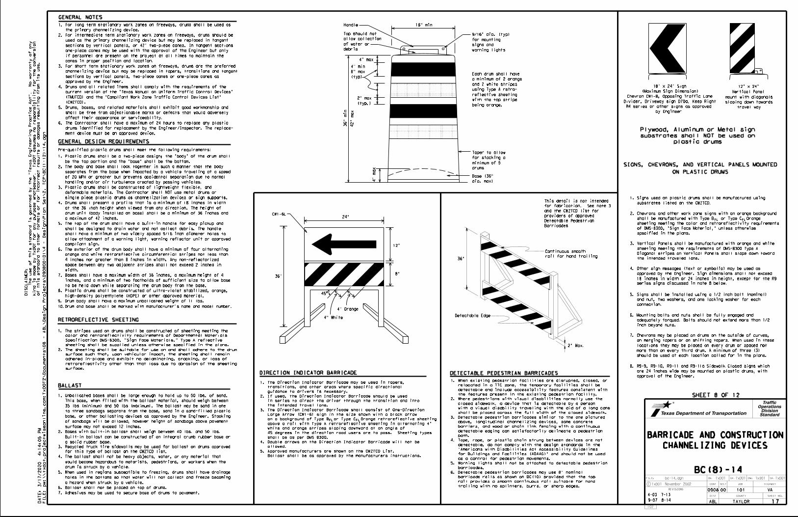
DN: CK: DW: CK:FILE:
0908 00 101
TAYLOR
JOB
COUNTY
SECT
DIST
REVISIONS
TxDOT TxDOT TxDOT TxDOT
ABL
HIGHWAY
VA
SHEET NO.
C TxDOT
CONT
bc-14.dgn
November 2002
pw:\\txdot.project
wiseonline.co
m:
Tx
DO
T2\
Docu
ments\08 -
AB
L\
Design
Projects\090800101\4 -
Design\
Plan
Set\2.
TC
P\
BC(1-12)-14.dgn
3/17/2020
4:14:05
PM
SHEET 8 OF 12
4-03
9-07
mount with diagonals
sloping down towards
travel way
(Maximum Sign Dimension)
18" x 24" Sign
1. For long term stationary work zones on freeways, drums shall be used as
the primary channelizing device.
2. For intermediate term stationary work zones on freeways, drums should be
used as the primary channelizing device but may be replaced in tangent
sections by vertical panels, or 42" two-piece cones. In tangent sections
if personnel are present on the project at all times to maintain the
cones in proper position and location.
3. For short term stationary work zones on freeways, drums are the preferred
approved by the Engineer.
4. Drums and all related items shall comply with the requirements of the
current version of the "Texas Manual on Uniform Traffic Control Devices"
(TMUTCD) and the "Compliant Work Zone Traffic Control Devices List"
(CWZTCD).
5. Drums, bases, and related materials shall exhibit good workmanship and
shall be free from objectionable marks or defects that would adversely
6. The Contractor shall have a maximum of 24 hours to replace any plastic
drums identified for replacement by the Engineer/Inspector. The replace-
ment device must be an approved device.
1. Plastic drums shall be a two-piece design; the "body" of the drum shall
be the top portion and the "base" shall be the bottom.
2. The body and base shall lock together in such a manner that the body
separates from the base when impacted by a vehicle traveling at a speed
of 20 MPH or greater but prevents accidental separation due to normal
handling and/or air turbulence created by passing vehicles.
3. Plastic drums shall be constructed of lightweight flexible, and
deformable materials. The Contractor shall NOT use metal drums or
single piece plastic drums as channelization devices or sign supports.
4. Drums shall present a profile that is a minimum of 18 inches in width
at the 36 inch height when viewed from any direction. The height of
drum unit (body installed on base) shall be a minimum of 36 inches and
a maximum of 42 inches.
5. The top of the drum shall have a built-in handle for easy pickup and
shall be designed to drain water and not collect debris. The handle
shall have a minimum of two widely spaced 9/16 inch diameter holes to
allow attachment of a warning light, warning reflector unit or approved
compliant sign.
6. The exterior of the drum body shall have a minimum of four alternating
orange and white retroreflective circumferential stripes not less than
4 inches nor greater than 8 inches in width. Any non-reflectorized
space between any two adjacent stripes shall not exceed 2 inches in
width.
7. Bases shall have a maximum width of 36 inches, a maximum height of 4
inches, and a minimum of two footholds of sufficient size to allow base
to be held down while separating the drum body from the base.
8. Plastic drums shall be constructed of ultra-violet stabilized, orange,
high-density polyethylene (HDPE) or other approved material.
Chevron CW1-8, Opposing Traffic Lane
Divider, Driveway sign D70a, Keep Right
channelizing device but may be replaced in tapers, transitions and tangent
one-piece cones may be used with the approval of the Engineer but only
1. Signs used on plastic drums shall be manufactured using
substrates listed on the CWZTCD.
2. Chevrons and other work zone signs with an orange background
3. Vertical Panels shall be manufactured with orange and white
4. Other sign messages (text or symbolic) may be used as
approved by the Engineer. Sign dimensions shall not exceed
5. Signs shall be installed using a 1/2 inch bolt (nominal)
and nut, two washers, and one locking washer for each
connection.
6. Mounting bolts and nuts shall be fully engaged and
adequately torqued. Bolts should not extend more than 1/2
inch beyond nuts.
7. Chevrons may be placed on drums on the outside of curves,
on merging tapers or on shifting tapers. When used in these
locations they may be placed on every drum or spaced not
more than on every third drum. A minimum of three (3)
should be used at each location called for in the plans.
approval of the Engineer.
8. R9-9, R9-10, R9-11 and R9-11a Sidewalk Closed signs which
are 24 inches wide may be mounted on plastic drums, with
Vertical Panel
12" x 24"
ON PLASTIC DRUMS
SIGNS, CHEVRONS, AND VERTICAL PANELS MOUNTED
by Engineer
R4 series or other signs as approved
GENERAL DESIGN REQUIREMENTS
GENERAL NOTES
1. The stripes used on drums shall be constructed of sheeting meeting the
1. Unballasted bases shall be large enough to hold up to 50 lbs. of sand.
This base, when filled with the ballast material, should weigh between
35 lbs (minimum) and 50 lbs (maximum). The ballast may be sand in one
to three sandbags separate from the base, sand in a sand-filled plastic
base, or other ballasting devices as approved by the Engineer. Stacking
of sandbags will be allowed, however height of sandbags above pavement
surface may not exceed 12 inches.
2. Bases with built-in ballast shall weigh between 40 lbs. and 50 lbs.
Built-in ballast can be constructed of an integral crumb rubber base or
a solid rubber base.
would become hazardous to motorists, pedestrians, or workers when the
drum is struck by a vehicle.
holes in the bottoms so that water will not collect and freeze becoming
a hazard when struck by a vehicle.
color and retroreflectivity requirements of Departmental Materials
2. The sheeting shall be suitable for use on and shall adhere to the drum
surface such that, upon vehicular impact, the sheeting shall remain
adhered in-place and exhibit no delaminating, cracking, or loss of
retroreflectivity other than that loss due to abrasion of the sheeting
surface.
24"
36"8"
12"
4" White
4" Orange
45o
CW1-6L
18" minHandle
36"
min
42"
max
4" max
4"
max
(typ)
8" max
4" min
(typ.)
2" max
dia. max)
Base (36"
drums
minimum of 5
for stacking a
Taper to allow
debris
of water or
allow collection
Top should not
warning lights
signs and
for mounting
9/16" dia. (typ)
DIRECTION INDICATOR BARRICADE DETECTABLE PEDESTRIAN BARRICADES
BALLAST
RETROREFLECTIVE SHEETING
10.Drum and base shall be marked with manufacturer's name and model number.
sections by vertical panels, two-piece cones or one-piece cones as
plastic drums
substrates shall NOT be used on
Plywood, Aluminum or Metal sign
36"
Barricades
Detectable Pedestrian
providers of approved
and the CWZTCD list for
for fabrication. See note 3
This detail is not intended
rail for hand trailing
Continuous smooth
Detectable Edge
2" Max.
trailing with no splinters, burrs, or sharp edges.
rail provides a smooth continuous rail suitable for hand
barricade rails as shown on BC(10) provided that the top
6. Detectable pedestrian barricades may use 8" nominal
barricades.
5. Warning lights shall not be attached to detectable pedestrian
as a control for pedestrian movements.
for Buildings and Facilities (ADAAG)" and should not be used
"Americans with Disabilities Act Accessibility Guidelines
detectable, do not comply with the design standards in the
4. Tape, rope, or plastic chain strung between devices are not
path.
detectable edging can satisfactorily delineate a pedestrian
barriers, and wood or chain link fencing with a continuous
above, longitudinal channelizing devices, some concrete
3. Detectable pedestrian barricades similar to the one pictured
shall be placed across the full width of the closed sidewalk.
with a visual disability traveling with the aid of a long cane
closed sidewalk, a device that is detectable by a person
2. Where pedestrians with visual disabilities normally use the
the features present in the existing pedestrian facility.
detectable and include accessibility features consistent with
relocated in a TTC zone, the temporary facilities shall be
1. When existing pedestrian facilities are disrupted, closed, or
9. Drum body shall have a maximum unballasted weight of 11 lbs.
for this type of ballast on the CWZTCD list.
3. Recycled truck tire sidewalls may be used for ballast on drums approved
4. The ballast shall not be heavy objects, water, or any material that
5. When used in regions susceptible to freezing, drums shall have drainage
6. Ballast shall not be placed on top of drums.
7. Adhesives may be used to secure base of drums to pavement.
series signs discussed in note 8 below.
18 inches in width or 24 inches in height, except for the R9
Specification DMS-8300, "Sign Face Materials." Type A reflective
sheeting shall be supplied unless otherwise specified in the plans.
FL
the intended traveled lane.
Diagonal stripes on Vertical Panels shall slope down toward
sheeting meeting the requirements of DMS-8300 Type A
FL
Ballast shall be as approved by the manufacturers instructions.
5. Approved manufacturers are shown on the CWZTCD List.
allowed.
4. Double arrows on the Direction Indicator Barricade will not be
shall be as per DMS 8300.
45 degrees in the direction road users are to pass. Sheeting types
white and orange stripes sloping downward at an angle of
above a rail with Type A retroreflective sheeting in alternating 4"
on a background of Type B or Type C Orange retroreflective sheeting
Large Arrow (CW1-6) sign in the size shown with a black arrow
3. The Direction Indicator Barricade shall consist of One-Direction
the intended travel lane.
in series to direct the driver through the transition and into
2. If used, the Direction Indicator Barricade should be used
guidance to drivers is necessary.
transitions, and other areas where specific directional
1. The Direction Indicator Barricade may be used in tapers,
FL
FL
specified in the plans.
of DMS-8300, "Sign Face Material," unless otherwise
sheeting meeting the color and retroreflectivity requirements
shall be manufactured with Type B or Type C Orange
being orange.
with the top stripe
reflective sheeting
using Type A retro-
and 2 white stripes
a minimum of 2 orange
Each drum shall have
7-13
CHANNELIZING DEVICES
BARRICADE AND CONSTRUCTION
FI
LE:
DA
TE:
102
StandardDivision
OperationsTraffic
Pre-qualified plastic drums shall meet the following requirements:
of this standard to other for
mats or for incorrect results or da
mages resulting fro
m its use.
kind is
made by
Tx
DO
T for any purpose
whatsoever.
Tx
DO
T assu
mes no responsibility for the conversion
The use of this standard is governed by the "
Texas
Engineering
Practice
Act".
No
warranty of any
DI
SC
LAI
ME
R:
affect their appearance or serviceability.
BC(8)-14
8-14 17

0908 00 101
TAYLORABL
VA
of this standard to other for
mats or for incorrect results or da
mages resulting fro
m its use.
kind is
made by
Tx
DO
T for any purpose
whatsoever.
Tx
DO
T assu
mes no responsibility for the conversion
The use of this standard is governed by the "
Texas
Engineering
Practice
Act".
No
warranty of any
DI
SC
LAI
ME
R:
FI
LE:
DA
TE:
pw:\\txdot.project
wiseonline.co
m:
Tx
DO
T2\
Docu
ments\08 -
AB
L\
Design
Projects\090800101\4 -
Design\
Plan
Set\2.
TC
P\
BC(1-12)-14.dgn
3/17/2020
4:14:07
PM
SHEET 9 OF 12
24"
min.
36"
min. distance above travel
way
45
VP-1L VP-1R
o
45o
36"
12"
36"
18"
18"
4"
4"
4"
4"
4"
4"
4"
4"
4"
DRIVEABLE
PORTABLE
FIXED
(Rigid or self-righting)
(Rigid or self-righting)
1. Work Zone channelizing devices illustrated on this sheet may be installed
in close proximity to traffic and are suitable for use on high or low
speed roadways. The Engineer/Inspector shall ensure that spacing and
placement is uniform and in accordance with the "Texas Manual on Uniform
Traffic Control Devices" (TMUTCD).
2. Channelizing devices shown on this sheet may have a driveable, fixed or
portable base. The requirement for self-righting channelizing devices must
be specified in the General Notes or other plan sheets.
3. Channelizing devices on self-righting supports should be used in work zone
areas where channelizing devices are frequently impacted by errant vehicles
or vehicle related wind gusts making alignment of the channelizing devices
difficult to maintain. Locations of these devices shall be detailed else-
where in the plans. These devices shall conform to the TMUTCD and the
"Compliant Work Zone Traffic Control Devices List" (CWZTCD).
damaged, nonreflective, faded, or broken devices and bases as required by
the Engineer/Inspector. The Contractor shall be required to maintain proper
device spacing and alignment.
5. Portable bases shall be fabricated from virgin and/or recycled rubber. The
6. Pavement surfaces shall be prepared in a manner that ensures proper bonding
between the adhesives, the fixed mount bases and the pavement surface.
Adhesives shall be prepared and applied according to the manufacturer's
recommendations.
7. The installation and removal of channelizing devices shall not cause
detrimental effects to the final pavement surfaces, including pavement
permitted on final pavement surfaces. The Engineer/Inspector shall approve
all application and removal procedures of fixed bases.
1. Opposing Traffic Lane Dividers (OTLD) are
delineation devices designed to convert a
normal one-way roadway section to two-way
operation. OTLD's are used on temporary
centerlines. The upward and downward arrows
on the sign's face indicate the direction of
traffic on either side of the divider. The
3. Spacing between the OTLD shall not exceed 500
the OTLD's should not exceed 100 foot spacing.
4. The OTLD shall be orange with a black non-
reflective legend. Sheeting for the OTLD shall
1. The chevron shall be a vertical rectangle with a
minimum size of 12 by 18 inches.
2. Chevrons are intended to give notice of a sharp
change of alignment with the direction of travel
and provide additional emphasis and guidance for
vehicle operators with regard to changes in
horizontal alignment of the roadway.
3. Chevrons, when used, shall be erected on the out-
side of a sharp curve or turn, or on the far side
of an intersection. They shall be in line with
and at right angles to approaching traffic.
Spacing should be such that the motorist always
has three in view, until the change in alignment
eliminates its need.
4. To be effective, the chevron should be visible
for at least 500 feet.
5. Chevrons shall be orange with a black nonreflec-
tive legend. Sheeting for the chevron shall be
6. For Long Term Stationary use on tapers or
transitions on freeways and divided highways
self-righting chevrons may be used to supplement
plastic drums but not to replace plastic drums.
4. The Contractor shall maintain devices in a clean condition and replace
surface discoloration or surface integrity. Driveable bases shall not be1. Vertical Panels (VP's) are normally used to channelize
traffic or divide opposing lanes of traffic.
2. VP's may be used in daytime or nighttime situations.
They may be used at the edge of shoulder drop-offs and
other areas such as lane transitions where positive
daytime and nighttime delineation is required. The
Engineer/Inspector shall refer to the Roadway Design
Manual Appendix B "Treatment of Pavement Drop-offs in
Work Zones" for additional guidelines on the use of
VP's for drop-offs.
3. VP's should be mounted back to back if used at the edge
of cuts adjacent to two-way two lane roadways. Stripes
are to be reflective orange and reflective white and
should always slope downward toward the travel lane.
of retroreflective area facing traffic.
5. Self-righting supports are available with portable base.
See "Compliant Work Zone Traffic Control Devices List"
(CWZTCD).
CW6-4
8" to 12" 8" to 12" 8" to 12" 8" to 12"
8" to 12"
WATER BALLASTED SYSTEMS USED AS BARRIERS
1. Water ballasted systems used as barriers shall not be used solely to channelize road users, but also to protect the
work space per the appropriate NCHRP 350 crashworthiness requirements based on roadway speed and barrier application.
2. Water ballasted systems used to channelize vehicular traffic shall be supplemented with retroreflective delineation
or channelizing devices to improve daytime/nighttime visibility. They may also be supplemented with pavement markings.
3. Water ballasted systems used as barriers shall be placed in accordance to application and installation requirements
specific to the device, and used only when shown on the CWZTCD list.
4. Water ballasted systems used as barriers should not be used for a merging taper except in low speed (less than 45 MPH)
urban areas. When used on a taper in a low speed urban area, the taper shall be delineated and the taper length
should be designed to optimize road user operations considering the available geometric conditions.
5. When water ballasted systems used as barriers have blunt ends exposed to traffic, they should be attenuated
Surface
RoadwayBase
Mount
Surface
min.
24"
min.
24"
Adhesive
w/ Approved
Fixed Base
depth
embedment
12" minimum
min.
36"
Support
Self-righting
Support
Rigid
Support can be used)
(Driveable Base, or Flexible
Fixed Base w/ Approved Adhesive
on drums.
mounted
or may be
may be used,
Driveable Base
Fixed or
Portable,
back to back
mounted
Panels
speed roadways, may have more than 270 square inches
unless noted otherwise.
conforming to Departmental Material Specification DMS-8300,
GENERAL NOTES
Taper lengths have been rounded off.
S=Posted Speed (MPH)
L=Length of Taper (FT.) W=Width of Offset (FT.) **
2
***
75 750'
720'
825' 900' 75'
60'
70'
80'
90'
100'
110'
120'
130'
140'
150'
30'
35'
40'
45'
50'
55'
60'
65'
70'
150'
205'
265'
450'
500'
550'
600'
165'
225'
295'
495'
550'
605'
660'
180'
320'
600'
660'
650' 715' 780'
245'
540'
700' 770' 840'
30
35
40
45
50
55
60
65
70
60
WSL=
Posted
Speed
On a
Tangent
On a
Taper
12'
OffsetOffset
11'
Offset
10'
Minimum
Desirable
Taper Lengths
Suggested Maximum
Spacing of
Channelizing
Devices
Formula
L=WS
80 800' 880' 960' 80' 160'
LONGITUDINAL CHANNELIZING DEVICES (LCD)
2. LCDs may be used instead of a line of cones or drums.
used only when shown on the CWZTCD list.
3. LCDs shall be placed in accordance to application and installation requirements specific to the device, and
4. LCDs should not be used to provide positive protection for obstacles, pedestrians or workers.
connected together. They are not designed to contain or redirect a vehicle on impact.
1. LCDs are crashworthy, lightweight, deformable devices that are highly visible, have good target value and can be
adhesive or rubber weight to minimize movement
base is secured to the pavement with an
caused by a vehicle impact or wind gust.
portable bases shall weigh a minimum of 30 lbs.
6. Sheeting for the VP's shall be retroreflective Type A
FL
FL
as per manufacturer recommendations or flared to a point outside the clear zone.
of the unit shall not be less than 32 inches in height.
systems must have a continuous detectable bottom for users of long canes and the top
If used to channelize pedestrians, longitudinal channelizing devices or water ballasted
2. The OTLD may be used in combination with 42"
cones or VPs.
feet. 42" cones or VPs placed between
the requirements of DMS-8300.
unless noted otherwise. The legend shall meet
to Departmental Material Specification DMS-8300,
be retroreflective Type B or Type C conforming FL
requirements of DMS-8300.
unless noted otherwise. The legend shall meet the
Departmental Material Specification DMS-8300,
retroreflective Type B or Type C conforming to FL
Min.
18"
12"
note 7
See
note 7
See
note 7
See
CHEVRONS
VERTICAL PANELS (VPs)
HOLLOW OR WATER BALLASTED SYSTEMS USED AS
LONGITUDINAL CHANNELIZING DEVICES OR BARRIERSOPPOSING TRAFFIC LANE DIVIDERS (OTLD)
MINIMUM DESIRABLE TAPER LENGTHS
CHANNELIZING DEVICES AND
SUGGESTED MAXIMUM SPACING OF
7. Where the height of reflective material on the vertical
6 inches shall be used.
panel is 36 inches or greater, a panel stripe of
4. VP's used on expressways and freeways or other high
7-13
CHANNELIZING DEVICES
BARRICADE AND CONSTRUCTION
DN: CK: DW: CK:FILE:
JOB
COUNTY
SECT
DIST
REVISIONS
TxDOT TxDOT TxDOT TxDOT
HIGHWAY
SHEET NO.
C TxDOT
BC(9)-14
CONT
bc-14.dgn
November 2002
103
StandardDivision
OperationsTraffic
9-07
LCD along the full length of the device.
sheeting meeting the requirements for barricade rails as shown on BC(10) placed near the top of the
6. LCDs used as barricades placed perpendicular to traffic should have at least one row of reflective
on BC(7) when placed roughly parallel to the travel lanes.
5. LCDs shall be supplemented with retroreflective delineation as required for temporary barriers
8-14
18

DN: CK: DW: CK:FILE:
0908 00 101
TAYLOR
JOB
COUNTY
SECT
DIST
REVISIONS
TxDOT TxDOT TxDOT TxDOT
ABL
HIGHWAY
VA
SHEET NO.
C TxDOT CONT
bc-14.dgn
November 2002
pw:\\txdot.project
wiseonline.co
m:
Tx
DO
T2\
Docu
ments\08 -
AB
L\
Design
Projects\090800101\4 -
Design\
Plan
Set\2.
TC
P\
BC(1-12)-14.dgn
3/17/2020
4:14:08
PM
104
SHEET 10 OF 12
9-07
2" max.3"-4"
1. Where positive redirectional
2. Plastic construction fencing
safety as required in the plans.
3. Vertical Panels on flexible support
capability is provided, drums
may be omitted.SB
SB
SB
SB
6" min.
4" min.
3" min.
3" min.
may be used with drums for
may be omitted if drums are used.
Detour
Roadway
R11-2
M4-10L DETOUR
ROAD
CLOSED
NAME
ADDRESS
CITY
STATE
CONTRACTOR
30 feet
2" min.
3"-4"
6" min.
4" min.
2" min.
shoulder width is less than 4 feet.
than 12 feet, steady-burn lights
42"
4"
4"
4"
4"
2"
2"
2" EDGELINE
CHANNELIZER
PLAN VIEW
PLAN VIEW
2. Advance signing shall be as specified elsewhere in the plans.
PERSPECTIVE VIEW
PERSPECTIVE VIEW
3"-4"
2" min.
10'
may be substituted for drums when the
4. When the shoulder width is greater
1. This device is intended only for use in place of a vertical panel to
2" min.
2" min.
4" min. orange
4" min. white
4" min. orange
4" min. white
Drums, vertical panels or 42" cones
STOCKPILE
channelize traffic by indicating the edge of the travel lane. It is
not intended to be used in transitions or tapers.
2. This device shall not be used to separate lanes of traffic (opposing
or otherwise) or warn of objects.
3. This device is based on a 42 inch, two-piece cone with an alternate
striping pattern: four 4 inch retroreflective bands, with an
approximate 2 inch gap between bands. The color of the band should
correspond to the color of the edgeline (yellow for left edgeline,
white for right edgeline) for which the device is substituted or for
which it supplements. The reflectorized bands shall be retroreflective
at 50' maximum spacing
omitted here
or barricade may be
downstream drums
On one-way roads
within 30' from travel lane.
should be used when stockpile is
Channelizing devices parallel to traffic
Two-Piece cones One-Piece cones Tubular Marker
G20-6T
SB
CONES
3" to 4"
2" to 6"
AlternateAlternate
clear zone.
is outside
stockpile location
Desirable
Plastic Drum
Typical
min.
28"
min.
28"
min.
28" min.
42"
on one-way roadway
are not required
These drums
barricaded in the same manner.
divided highway shall be
Each roadway of a
and maximum of 4 drums)
width makes it necessary. (minimum of 2
side of approaching traffic if the crown
Increase number of plastic drums on the
be used across the
work area.
A
mini
mu
m of t
wo dru
ms shall
50'
Approx.
50'
Approx.
1. Refer to the Compliant Work Zone Traffic Control Devices List (CWZTCD)
projects closed to all traffic.
3. Barricades extending across a roadway should have stripes that slope
downward in the direction toward which traffic must turn in detouring.
When both right and left turns are provided, the chevron striping may
slope downward in both directions from the center of the barricade.
Where no turns are provided at a closed road striping should slope
downward in both directions toward the center of roadway.
4. Striping of rails, for the right side of the roadway, should slope
downward to the left. For the left side of the roadway, striping
should slope downward to the right.
5. Identification markings may be shown only on the back of the
barricade rails. The maximum height of letters and/or company logos
used for identification shall be 1".
6. Barricades shall not be placed parallel to traffic unless an adequate
clear zone is provided.
7. Warning lights shall NOT be installed on barricades.
8. Where barricades require the use of weights to keep from turning over,
the use of sandbags with dry, cohesionless sand is recommended. The
sandbags will be tied shut to keep the sand from spilling and to
maintain a constant weight. Sand bags shall not be stacked in a manner
that covers any portion of a barricade rails reflective sheeting.
Rock, concrete, iron, steel or other solid objects will NOT be
permitted. Sandbags should weigh a minimum of 35 lbs and a maximum of
50 lbs. Sandbags shall be made of a durable material that tears upon
vehicular impact. Rubber (such as tire inner tubes) shall not be used
for sandbags. Sandbags shall only be placed along or upon the base
supports of the device and shall not be suspended above ground level
or hung with rope, wire, chains or other fasteners.
be used as a sign support.
Barricades shall NOT
10'
max.
10'
max.
10'
max.
4. The base must weigh a minimum of 30 lbs.
or yellow warning reflector
Steady burn warning light
or yellow warning reflector
Plastic drum with steady burn light
Plastic drum
LEGEND
of the culvert widening.
5. Drums must extend the length
30 lbs. including base.
42" 2-piece cones shall have a minimum weight of
28" Cones shall have a minimum weight of 9 1/2 lbs.
CULVERT WIDENING OR OTHER ISOLATED WORK WITHIN THE PROJECT LIMITS
TRAFFIC CONTROL FOR MATERIAL STOCKPILES
TYPICAL PANEL DETAIL
FOR SKID OR POST TYPE BARRICADES
TYPICAL STRIPING DETAIL FOR BARRICADE RAIL
8' max. length Type 3 Barricades
downward in the direction of detour.
Barricade striping should slant
for two-way traffic.
facing one-way traffic and both sides
reflective white stripes on one side
shall be reflectorized orange and
The three rails on Type 3 barricades
barricade
or 1 Type 3
Min. 2 drums
barricade
or 1 Type 3
Min. 2 drums
TYPE 3 BARRICADES
2. Type 3 Barricades shall be used at each end of construction
TYPE 3 BARRICADE (POST AND SKID) TYPICAL APPLICATION
minimum of 10 feet behind Type 3 Barricades.
mounting height in center of roadway. The signs should be a
1. Signs should be mounted on independent supports at a 7 foot
1. Traffic cones and tubular markers shall be predominantly orange, and
meet the height and weight requirements shown above.
2. One-piece cones have the body and base of the cone molded in one consolidated
unit. Two-piece cones have a cone shaped body and a separate rubber base,
or ballast, that is added to keep the device upright and in place.
height shown, in order to aid in retrieving the device.
3. Two-piece cones may have a handle or loop extending up to 8" above the minimum
reflective bands as shown above. The reflective bands shall have a smooth, sealed
7. Cones or tubular markers used on each project should be of the same size
and shape.
to maintain them in their proper upright position.
for intermediate-term or long-term stationary work unless personnel is on-site
short-term stationary work as defined on BC(4). These should not be used
5. 28" cones and tubular markers are generally suitable for short duration and
durations.
6. 42" two-piece cones, vertical panels or drums are suitable for all work zone
4. Cones or tubular markers used at night shall have white or white and orange
DMS-8300 Type A.
outer surface and meet the requirements of Departmental Material Specification
unless otherwise noted.
Type A conforming to Departmental Material Specification DMS-8300,
45o
6" 6" 7 inches.
Sheeting
Reflective
Width of
Minimum
nominal
8"
7-13
StandardDivision
OperationsTraffic
PROJECTS LET AFTER MARCH 2014.
THIS DEVICE SHALL NOT BE USED ON
BC(10)-14
CHANNELIZING DEVICES
BARRICADE AND CONSTRUCTION
of this standard to other for
mats or for incorrect results or da
mages resulting fro
m its use.
kind is
made by
Tx
DO
T for any purpose
whatsoever.
Tx
DO
T assu
mes no responsibility for the conversion
The use of this standard is governed by the "
Texas
Engineering
Practice
Act".
No
warranty of any
DI
SC
LAI
ME
R:
FI
LE:
DA
TE:
to Departmental Material Specification DMS-8300 unless otherwise noted.
9. Sheeting for barricades shall be retroreflective Type A conforming
for details of the Type 3 Barricades and a list of all materials
used in the construction of Type 3 Barricades.
20"
20"
48"
Flat rail
Stiffener
2 stiffeners shall be allowed on one barricade.
Stiffener may be inside or outside of support, but no more than
4' min., 8' max.
8-14
19

0908 00 101
TAYLORABL
VA
of this standard to other for
mats or for incorrect results or da
mages resulting fro
m its use.
kind is
made by
Tx
DO
T for any purpose
whatsoever.
Tx
DO
T assu
mes no responsibility for the conversion
The use of this standard is governed by the "
Texas
Engineering
Practice
Act".
No
warranty of any
DI
SC
LAI
ME
R:
FI
LE:
DA
TE:
pw:\\txdot.project
wiseonline.co
m:
Tx
DO
T2\
Docu
ments\08 -
AB
L\
Design
Projects\090800101\4 -
Design\
Plan
Set\2.
TC
P\
BC(1-12)-14.dgn
3/17/2020
4:14:10
PM
SHEET 11 OF 12
TOP VIEW FRONT VIEW SIDE VIEW
Adhesive pad
4"+ ‚"
2"
GENERAL REMOVAL OF PAVEMENT MARKINGS
1. The Contractor shall be responsible for maintaining work zone and
within the CSJ limits unless otherwise stated in the plans.
2. Color, patterns and dimensions shall be in conformance with the
"Texas Manual on Uniform Traffic Control Devices" (TMUTCD).
3. Additional supplemental pavement marking details may be found in the
plans or specifications.
4. Pavement markings shall be installed in accordance with the TMUTCD
and as shown on the plans.
5. When short term markings are required on the plans, short term
markings shall conform with the TMUTCD, the plans and details as
shown on the Standard Plan Sheet WZ(STPM).
6. When standard pavement markings are not in place and the roadway
is opened to traffic, DO NOT PASS signs shall be erected to mark
the beginning of the sections where passing is prohibited and
PASS WITH CARE signs at the beginning of sections where passing
is permitted.
7. All work zone pavement markings shall be installed in accordance
with Item 662, "Work Zone Pavement Markings."
RAISED PAVEMENT MARKERS
1. Raised pavement markers are to be placed according to the patterns
on BC(12).
2. All raised pavement markers used for work zone markings shall meet
PREFABRICATED PAVEMENT MARKINGS
1. Removable prefabricated pavement markings shall meet the requirements
of DMS-8241.
2. Non-removable prefabricated pavement markings (foil back) shall meet
the requirements of DMS-8240.
MAINTAINING WORK ZONE PAVEMENT MARKINGS
1. The Contractor will be responsible for maintaining work zone pavement
markings within the work limits.
2. Work zone pavement markings shall be inspected in accordance with
the frequency and reporting requirements of work zone traffic control
device inspections as required by Form 599.
3. The markings should provide a visible reference for a minimum
distance of 300 feet during normal daylight hours and 160 feet when
illuminated by automobile low-beam headlights at night, unless sight
distance is restricted by roadway geometrics.
4. Markings failing to meet this criteria within the first 30 days after
placement shall be replaced at the expense of the Contractor as per
Specification Item 662.
days, where flaggers and/or sufficient channelizing devices are used
in lieu of markings to outline the detour route.
3. Pavement markings shall be removed to the fullest extent possible,
so as not to leave a discernable marking. This shall be by any method
approved by TxDOT Specification Item 677 for "Eliminating Existing
Pavement Markings and Markers".
4. The removal of pavement markings may require resurfacing or seal
5. Subject to the approval of the Engineer, any method that proves to be
successful on a particular type pavement may be used.
6. Blast cleaning may be used but will not be required unless specifically
7. Over-painting of the markings SHALL NOT BE permitted.
8. Removal of raised pavement markers shall be as directed by the
Engineer.
9. Removal of existing pavement markings and markers will be paid for
directly in accordance with Item 677, "ELIMINATING EXISTING PAVEMENT
MARKINGS AND MARKERS," unless otherwise stated in the plans.
10.Black-out marking tape may be used to cover conflicting existing
markings for periods less than two weeks when approved by the Engineer.
1. Temporary flexible-reflective roadway marker tabs used as guidemarks
shall meet the requirements of DMS-8242.
2. Tabs detailed on this sheet are to be inspected and accepted by the
Engineer or designated representative. Sampling and testing is not
normally required, however at the option of the Engineer, either "A"
or "B" below may be imposed to assure quality before placement on the
roadway.
B. Select five (5) tabs and perform the following test. Affix five
(5) tabs at 24 inch intervals on an asphaltic pavement in a
straight line. Using a medium size passenger vehicle or pickup,
run over the markers with the front and rear tires at a speed
of 35 to 40 miles per hour, four (4) times in each direction. No
more than one (1) out of the five (5) reflective surfaces shall
be lost or displaced as a result of this test.
3. Small design variances may be noted between tab manufacturers.
4. See Standard Sheet WZ(STPM) for tab placement on new pavements. See
1. Raised pavement markers used as guidemarks shall be from the approved
product list, and meet the requirements of DMS-4200.
3. Adhesive for guidemarks shall be bituminous material hot applied or
butyl rubber pad for all surfaces, or thermoplastic for concrete
surfaces.
Guidemarks shall be designated as:
YELLOW - (two amber reflective surfaces with yellow body).
WHITE - (one silver reflective surface with white body).
Standard Sheet TCP(7-1) for tab placement on seal coat work.
TABS TO THE PAVEMENT SURFACE
TEMPORARY FLEXIBLE-REFLECTIVE ROADWAY MARKER
STAPLES OR NAILS SHALL NOT BE USED TO SECURE
1/4" and less than 1".
is usually more than
Height of sheeting
WORK ZONE PAVEMENT MARKINGSRoadway Marker Tabs
Temporary Flexible-ReflectiveDEPARTMENTAL MATERIAL SPECIFICATIONS
DMS-6130
EPOXY AND ADHESIVES DMS-6100
DMS-4300
DMS-8240
DMS-8241
DMS-8242
DMS-4200
TRAFFIC BUTTONS
PERMANENT PREFABRICATED PAVEMENT MARKINGS
PAVEMENT MARKINGS
TEMPORARY REMOVABLE, PREFABRICATED
ROADWAY MARKER TABS
TEMPORARY FLEXIBLE, REFLECTIVE
A list of prequalified reflective raised pavement markers,
non-reflective traffic buttons, roadway marker tabs and other
pavement markings can be found at the Material Producer List
web address shown on BC(1).
BITUMINOUS ADHESIVE FOR PAVEMENT MARKERS
PAVEMENT MARKERS (REFLECTORIZED)
RAISED PAVEMENT MARKERS USED AS GUIDEMARKS
project shall be of the same manufacturer.
2. All temporary construction raised pavement markers provided on a
the requirements of Item 672, "RAISED PAVEMENT MARKERS" and Departmental
Material Specification DMS-4200 or DMS-4300.
shown in the plans.
existing pavement markings, in accordance with the standard
specifications and special provisions, on all roadways open to traffic
1. Pavement markings that are no longer applicable, could create confusion
or direct a motorist toward or into the closed portion of the roadway
shall be removed or obliterated before the roadway is opened to traffic.
Section to determine specification compliance.
and submit to the Construction Division, Materials and Pavement
A. Select five (5) or more tabs at random from each lot or shipment
2. The above shall not apply to detours in place for less than three
coating portions of the roadway as described in Item 677.
7-13
PAVEMENT MARKINGS
BARRICADE AND CONSTRUCTION
DN: CK: DW: CK:FILE:
JOB
COUNTY
SECT
DIST
REVISIONS
TxDOT TxDOT TxDOT TxDOT
HIGHWAY
SHEET NO.
C TxDOT
BC(11)-14
CONT
bc-14.dgn
February 1998
105
StandardDivision
OperationsTraffic
9-07
11-02
1-02
2-98
8-14 20

DN: CK: DW: CK:FILE:
0908 00 101
TAYLOR
JOB
COUNTY
SECT
DIST
REVISIONS
TxDOT TxDOT TxDOT TxDOT
ABL
HIGHWAY
VA
SHEET NO.
C TxDOT
CONT
bc-14.dgn
February 1998
pw:\\txdot.project
wiseonline.co
m:
Tx
DO
T2\
Docu
ments\08 -
AB
L\
Design
Projects\090800101\4 -
Design\
Plan
Set\2.
TC
P\
BC(1-12)-14.dgn
3/17/2020
4:14:11
PM
106
SHEET 12 OF 12
9-071-97
2-98
11-02
10 to 12"
PAVEMENT MARKING PATTERNS
Yellow
Yellow
White
White
Yellow
Yellow
Yellow
Type II-A-A Type II-A-A
Type Y buttons
Type Y buttons
Type II-A-A
Type II-A-A
Type I-A
Type I-A
Type W buttons
Type I-C
Type Y buttons
Type Y buttons
Type W buttons
Type I-C
Type I-C or II-C-R
Type I-C or II-C-R 10' 30'
-
-
-
DISCOURAGE LANE CHANGING.)
EDGE LINE
OR SINGLE
Yellow
White
White or Yellow
White or Yellow
NO-PASSING LINE
WIDE
LINE
(FOR LEFT TURN CHANNELIZING LINE
OR CHANNELIZING LINE USED TO
Type Y buttons
Type I-C , I-A or II-A-A Type W or Y buttons
Type I-C Type W buttons
Type I-C or II-A-A
STANDARD WORK ZONE PAVEMENT MARKINGS DETAILS
Type II-A-A
REMOVABLE MARKINGS
WITH RAISED
PAVEMENT MARKERS
Type I-C or II-A-A
(when required)
Raised Pavement MarkersIf raised pavement markers are used
to supplement REMOVABLE markings,
the markers shall be applied to the
top of the tape at the approximate
mid length of tape used for broken
60" + 3"
-REFLECTORIZED PAVEMENT MARKINGS - PATTERN B
REFLECTORIZED PAVEMENT MARKINGS - PATTERN A
REFLECTORIZED PAVEMENT MARKINGS
10 to 12"
4 to 8" 6 to 8"
60" + 3"
60" + 3"
4"
4 to 12"
4 to 12"
4"
8"
1-2"
10'
10' 30'
40' + 1'
5' + 6"
20' + 1'
30'
RAISED PAVEMENT MARKERS - PATTERN A
RAISED PAVEMENT MARKERS - PATTERN B
RAISED PAVEMENT MARKERS
Pattern A is the TXDOT Standard, however Pattern B may be used if approved by the Engineer.
lines or at 20 foot spacing for
solid lines. This allows an easier
removal of raised pavement markers
and tape.Centerline only - not to be used on edge lines
Prefabricated markings may be substituted for reflectorized pavement markings.
Prefabricated markings may be substituted for reflectorized pavement markings.
MARKINGS
PAVEMENT
REFLECTORIZED
MARKINGS
PAVEMENT
REFLECTORIZED
LINE
NO-PASSING
DOUBLE
MARKINGS
PAVEMENT
REFLECTORIZED
MARKERS
PAVEMENT
RAISED
MARKERS
PAVEMENT
RAISED
MARKERS
PAVEMENT
RAISED
MARKERS
PAVEMENT
RAISED
Type II-A-A
3' 9'
5' 5'
8"
3' 9'
Type I-C or II-C-RMARKERS
PAVEMENT
RAISED
MARKERS
PAVEMENT
RAISEDLINE
LANEDROP
OR
AUXILIARY
LINE
LANE
OR
LINE
CENTER
Item 672 "RAISED PAVEMENT MARKERS."
products list and meet the requirements of
pavement markings shall be from the approved
Raised pavement markers used as standard
TWO-WAY LEFT TURN LANE
LANE & CENTER LINES FOR MULTILANE UNDIVIDED HIGHWAYS
EDGE & LANE LINES FOR DIVIDED HIGHWAY
CENTER LINE & NO-PASSING ZONE BARRIER LINES FOR TWO-LANE, TWO-WAY HIGHWAYS
LINES
SOLID
LINES
BROKEN
7-13
StandardDivision
OperationsTraffic
PAVEMENT MARKING PATTERNS
BARRICADE AND CONSTRUCTION
of this standard to other for
mats or for incorrect results or da
mages resulting fro
m its use.
kind is
made by
Tx
DO
T for any purpose
whatsoever.
Tx
DO
T assu
mes no responsibility for the conversion
The use of this standard is governed by the "
Texas
Engineering
Practice
Act".
No
warranty of any
DI
SC
LAI
ME
R:
FI
LE:
DA
TE:
Yellow
White
White
Type Y buttons
Type I-C
Type II-A-A
Type I-C
REFLECTORIZED PAVEMENT MARKINGS RAISED PAVEMENT MARKERS
Prefabricated markings may be substituted for reflectorized pavement markings.
Yellow
White
WhiteType Y buttonsType II-A-A
Type I-C
Type I-C
REFLECTORIZED PAVEMENT MARKINGS RAISED PAVEMENT MARKERS
Prefabricated markings may be substituted for reflectorized pavement markings.
8-14
BC(12)-14
21

CK: DW: CK:FILE:
0908 00 101
TAYLOR
JOB
COUNTY
SECT
DIST
REVISIONS
ABL
HIGHWAY
VA
SHEET NO.
C TxDOT
of this standard to other for
mats or for incorrect results or da
mages resulting fro
m its use.
kind is
made by
Tx
DO
T for any purpose
whatsoever.
Tx
DO
T assu
mes no responsibility for the conversion
The use of this standard is governed by the "
Texas
Engineering
Practice
Act".
No
warranty of any
DI
SC
LAI
ME
R:
CONT
FI
LE:
DA
TE:
pw:\\txdot.project
wiseonline.co
m:
Tx
DO
T2\
Docu
ments\08 -
AB
L\
Design
Projects\090800101\4 -
Design\
Plan
Set\2.
TC
P\
TC
P(2-1)-18.dgn
3/17/2020
4:14:15
PM
StandardDivision
OperationsTraffic
Work
Space
Shoulder
Shoulder
Shoulder
TCP (2-1b) TCP (2-1c)
WORK SPACE ON SHOULDER WORK VEHICLES ON SHOULDER
See note 1)
48" X 48"
(Flags-
CW20-1D
CW20-1D
48" X 48"
See note 1)
(Flags-
(See note 2)
G20-2
48" X 24"
Shoulder
Shoulder
See note 1)
48" X 48"
(Flags-
CW20-1D
48" X 24"
(See note 2)
G20-2
See note 1)
48" X 48"
(Flags-
CW20-1D
(See note 2)
G20-2
48" X 24"
48" X 24"
(See note 2)
G20-2
Right-of-
way
Line
Approx.
100'
Shoulder
Shoulder
Min.
30'
Work
Space
100'
Min.
30'
1/3
LB
1/3
LB
Work
Space
Min.
30'
Min.
10'
100'
Shoulder
Shoulder
Shoulder
Shoulder
Shoulder
Approx.
100'
See note 1)
48" X 48"
(Flags-
CW20-1D
Min.
30'
Min.
30'
Min.
30'
Min.
10'
x for 50
mph or less
3x for over 50
mph
or less
x for 50
mph
50
mph
3x for over
50
mph
3x for over
or less
x for 50
mph
(See notes 4 & 5)
(See notes 4 & 5)
CW20-1D
48" X 48"
See note 1)
(Flags-
nearest traveled way.
of 30' from the
work area is a minimum
may be omitted if the
Channelizing devices
at all times.
channelizing devices
lanes of traffic by
areas separated from
etc., shall remain in
moveable cranes,
such as trucks,
work operation,
necessary for the
or other equipment
Work vehicles
TCP (2-1a)
WORK SPACE NEAR SHOULDER
Conventional Roads Conventional Roads Conventional Roads
or less
x for 50
mph
or less
x for 50
mph
or less
x for 50
mph
50
mph
3x for over
50
mph
3x for over
50
mph
3x for over
(See Note 7)
work vehicle
Inactive
(See notes 4 & 5)
Type 3 Barricade
Heavy Work Vehicle
Channelizing Devices
Flag
LEGEND
Flagger
Sign
Message Sign (PCMS)
Portable Changeable
Flashing Arrow Board
Trailer Mounted
M
Traffic Flow
Attenuator (TMA)
Truck Mounted
L=Length of Taper(FT) W=Width of Offset(FT) S=Posted Speed(MPH)
Taper lengths have been rounded off.
Conventional Roads Only***
2
***
75 750'
720'
825' 900' 75' 900' 540'
90'
120'
155'
195'
240'
295'
350'
410'
475'
60'
70'
80'
90'
100'
110'
120'
130'
140'
150'
120'
160'
240'
320'
400'
500'
700'
600'
800'
30'
35'
40'
45'
50'
55'
60'
65'
70'
150'
205'
265'
450'
500'
550'
600'
165'
225'
295'
495'
550'
605'
660'
180'
320'
600'
660'
650' 715' 780'
245'
540'
700' 770' 840'
30
35
40
45
50
55
60
65
70
60
WSL=
Posted
Speed
"B"
Buffer Space
Longitudinal
Suggested
Tangent
On a
Taper
On a12'
OffsetOffset
11'
Offset
10'
Taper Lengths
Desirable
Minimum
Devices
Channelizing
Spacing of
Suggested Maximum
Formula
L=WS
Spacing
Sign
Minimum
Distance
"X"
TERM STATIONARY
INTERMEDIATE
STATIONARY
LONG TERM
STATIONARY
SHORT TERM
TYPICAL USAGE
MOBILEDURATION
SHORT
GENERAL NOTES
SHOULDER WORK
CONVENTIONAL ROAD
TRAFFIC CONTROL PLAN
2-94
8-95
1-97
4-98
161
2-12
December 1985
TCP(2-1)-18
2-18
DN:tcp2-1-18.dgn
"ROAD WORK AHEAD" signs for shoulder work on conventional roadways.
8. CW21-5 "SHOULDER WORK" signs may be used in place of CW20-1D
right-of-way line and not parked on the paved shoulder.
7. Inactive work vehicles or other equipment should be parked near the
freeways.
6. See TCP(5-1) for shoulder work on divided highways, expressways and
surface, next to those shown in order to protect a wider work space.
5. Additional Shadow Vehicles with TMAs may be positioned off the paved
substituted for the Shadow Vehicle and TMA.
place, Type 3 Barricades or other channelizing devices may be
but road or work conditions require the traffic control to remain in
performance or quality of the work. If workers are no longer present
the area of crew exposure without adversely affecting the
used anytime it can be positioned 30 to 100 feet in advance of
oscillating or strobe lights. A Shadow Vehicle with a TMA should be
4. Shadow Vehicle with TMA and high intensity rotating, flashing,
nearest traveled way.
3. Stockpiled material should be placed a minimum of 30 feet from
plans, or for routine maintenance work, when approved by the Engineer.
denoted with the triangle symbol may be omitted when stated in the
2. All traffic control devices illustrated are REQUIRED, except those
1. Flags attached to signs where shown, are REQUIRED.
22

DN: CK: DW: CK:FILE:
0908 00 101
TAYLOR
JOB
COUNTY
SECT
DIST
REVISIONS
TxDOT TxDOT TxDOT TxDOT
ABL
HIGHWAY
VA
SHEET NO.
C TxDOT
of this standard to other for
mats or for incorrect results or da
mages resulting fro
m its use.
kind is
made by
Tx
DO
T for any purpose
whatsoever.
Tx
DO
T assu
mes no responsibility for the conversion
The use of this standard is governed by the "
Texas
Engineering
Practice
Act".
No
warranty of any
DI
SC
LAI
ME
R:
CONT
FI
LE:
DA
TE:
pw:\\txdot.project
wiseonline.co
m:
Tx
DO
T2\
Docu
ments\08 -
AB
L\
Design
Projects\090800101\4 -
Design\
Plan
Set\2.
TC
P\
TC
P(3-1)-13
3/17/2020
4:14:18
PM
175
UNDIVIDED HIGHWAYS
MOBILE OPERATIONS
TRAFFIC CONTROL PLAN
TCP(3-1)-13
1500'+ Approx.
with strobes
Work Vehicle
Work Vehicle
with strobes
Heavy Work Vehicle
LEGEND
Traffic Flow
Trail Vehicle
Shadow Vehicle
Work Vehicle
ARROW BOARD DISPLAY
RIGHT Directional
LEFT Directional
with strobes
Work Vehicle
Shoulder
Shoulder
UNDIVIDED MULTILANE ROADWAY
TCP (3-1a)
Shoulder
WORK ON SHOULDER
TCP (3-1b)
TWO-WAY ROADWAY WITH PAVED SHOULDERS
TCP (3-1c)
1500'+ Approx.
Shoulder
Attenuator (TMA)
Truck Mounted
with strobes
Lead Vehicle
TWO-WAY ROADWAY WITHOUT PAVED SHOULDERS
Approx.Approx.
with strobes
Lead Vehicle
WORK ON TRAVEL LANE
1500'+ Approx.
120'-200' Approx. 120'-200' Approx.1500'+ Approx.
120'-200' 120'-200'
with strobes
Lead Vehicle
120'-200'
Approx.
Approx.
120'-200' 120'-200'
Red Reflective
8"
8"
(H
EI
GH
T
OF
TM
A)
-+
+ -
45o
STRIPING FOR TMA
(WIDTH OF TMA)
White Reflective
6"
6"
OR
60" X 36"
CW21-10aT
72" X 36"
CW21-10cT
3'
+
6'
+
OR
2-94
8-95
1-97
4-98
December 1985
3'
+
6'
+
OR
60" X 36"
CW21-10aT
72" X 36"
CW21-10cT
display Flashing Arrow Board
with RIGHT Directional
Double Arrow
Diamond or 4 Corner Flash)
CAUTION (Alternating
See note 8See note 8
See note 8
See note 8
See note 8
See note 8
See note 8
Approx.
Arrow Board
Forward Facing
Arrow Board
Facing
Forward
Arrow Board
Forward Facing
Trail/Shadow Vehicle A
See Note 9 and
TRAIL/SHADOW VEHICLE A
TRAIL/SHADOW VEHICLE B
Trail/Shadow Vehicle B
See note 9 and
Vehicle ATrail/Shadow
See note 9 and
Trail/Shadow Vehicle B
See note 9 and
in CAUTION display
with Flashing Arrow Board
GENERAL NOTES
TERM STATIONARY
INTERMEDIATE
STATIONARY
LONG TERM
STATIONARY
SHORT TERM
TYPICAL USAGE
MOBILEDURATION
SHORT
rearmost protection vehicle.
pass the work convoy, a "DO NOT PASS" (R4-1) sign should be placed on the back of the
periodically to allow motor vehicle traffic to pass. If motorists are not allowed to
10. On two-lane two-way roadways, the work and protection vehicles should pull over
if a TRAIL VEHICLE is used.
"X" location. The "X VEHICLE CONVOY" sign shall not be used on the SHADOW VEHICLE
the number of the convoy vehicles displayed on the sign in the number designation
adequate mounting space exists. When used, the X VEHICLE CONVOY sign shall have
"WORK CONVOY"(CW21-10T) or "X VEHICLE CONVOY" (CW21-10bT) signs may be used where
TRAIL VEHICLES and SHADOW VEHICLES as shown. As an option 48" X 48" diamond shaped
9. "X VEHICLE CONVOY" (CW21-10cT) or "WORK CONVOY" (CW21-10aT) signs shall be used on
vary according to terrain, work activity and other factors.
and SHADOW VEHICLE and vehicle spacing between WORK VEHICLE and LEAD VEHICLE may
they approach the TRAIL VEHICLE. Vehicle spacing between the WORK VEHICLE
should be able to see the TRAIL VEHICLE in time to slow down and/or change lanes as
depending on sight distance restrictions. Motorists approaching the work convoy
8. Vehicle spacing between the TRAIL VEHICLE and the SHADOW VEHICLE will vary
shadow the other convoy vehicles.
7. When work convoys must change lanes, the TRAIL VEHICLE should change lanes first to
6. Each vehicle shall have two-way radio communication capability.
Construction (BC) standards. The board shall be controlled from inside the vehicle.
5. Flashing arrow boards shall be Type B or Type C as per the Barricade and
color requirements of DEPARTMENTAL MATERIAL SPECIFICATION DMS 8300, Type A.
4. Reflective sheeting on the rear of the TMA shall meet or exceed the reflectivity and
are required.
3. The use of truck mounted attenuators (TMA) on the SHADOW VEHICLE and TRAIL VEHICLE
simultaneously with the amber beacons or strobe lights.
strobe lights when mounted on the driver's side of the vehicle may be operated
on vehicles are required. Blue high intensity rotating, flashing, oscillating or
2. The use of amber high intensity rotating, flashing, oscillating, or strobe lights
traffic volume, and sight distance restrictions.
and/or TRAIL VEHICLE are required based on prevailing roadway conditions,
equipped with an arrow board. The Engineer will determine if the LEAD VEHICLE
illustrated. When a LEAD vehicle is not used the WORK vehicle must be
1. TRAIL, SHADOW, and LEAD vehicles shall be equipped with arrow boards as
7-13
StandardDivision
OperationsTraffic
tcp3-1.dgn
23

RUNNING BOND
8"
4"
THIS DOCUMENT IS RELEASED
FOR THE PURPOSE OF PRELIMINARY
REVIEW UNDER THE AUTHORITY OF
BRANDON M. VINSON, P.E. 130093
IT IS NOT TO BE USED FOR BIDDING,
CONSTRUCTION, OR PERMITTING PURPOSES.
DATE: 3/17/2020
DA
TE:
FI
LE:
4:14:23
PM
3/17/2020
pw:\\txdot.project
wiseonline.co
m:
Tx
DO
T2\
Docu
ments\08 -
AB
L\
Design
Projects\090800101\4 -
Design\
Plan
Set\3.
Road
way\
PA
VE
R
PA
TT
ER
NS.dgn
COUNTY
JOB
HIGHWAY NO.
TEXAS
DISTRICT SECTIONCONTROL
TAYLOR
0908 00 101
PROJECT NO.
6
ABL
DIVISION
FHWA
STATE SHEET NO.
24
VA
PAVER PATTERN DETAIL
SCALE: N/A SHEET 1 OF 1
SEE TITLE SHEET
C
Texas Department of Transportation
2020 R
BASKET WEAVE
8"
4"
HERRINGBONE
8"
4"
8"
4"
STACKED
1 PAVER
1 PAVER
1 PAVER
1 PAVER
1/8" MAX
1/8"
MA
X
1/8"
MA
X
1/8" MAX
1/8"
MA
X
1/8" MAX
1/8" MAX
1/8"
MA
X

CONCRETE RING
PAVERS
CITY
PLAQUE
18"
20"
6"
6"
32"
A A
PAVER EMBLEM
OUTER CONCRETE RING
SECTION A-A
BOLT (TYP.)THREADED
CONCRETE RING
MATERIAL1/2" EXPANSION FOOTING
4" CONCRETE
GRADEMATCH EXISTING
THREADED BOLT
2"
MI
N.
CITY PLAQUE
FOOTING4" CONCRETE
30"
NOTES
SUBSIDIARY TO THE VARIOUS BID ITEMS.
AND PROTECTION OF PLAQUES SHALL BE CONSIDERED
"RIPRAP". INSTALLATION OF PLAQUES, BOLTS, CLEANING
5) CONCRETE FOOTING SHALL BE PAID FOR UNDER ITEM 432
OR THE CITY OF ABILENE.
REPLACE DAMAGED PLAQUES AT NO EXPENSE TO THE STATE
PLAQUES DURING THE INSTALLATION OR CLEANING.
4) CONTRACTOR WILL BE RESPONSIBLE FOR ANY DAMAGE TO
SPLATTER THAT GETS ON VISIBLE SURFACES OF PLAQUES.
ARE LEFT AROUND BOLTS. PROTECT OR CLEAN ANY
CONCRETE. VIBRATE CONCRETE TO ENSURE NO VOIDS
3) THREAD BOLTS INTO PLAQUE AND PUSH INTO FRESH
USE HEX-HEAD BOLTS.
OF BOLTS REQUIRED AFTER RECIEPT OF PLAQUES.
BOLTS (4 FOR EACH PLAQUE). VERIFY DIMENSIONS
2) THE CONTRACTOR SHALL PROVIDE THE THREADED
INSTALLTION AT EACH OF THE 5 LOCATIONS.
5 PLAQUES TO THE CONTRACTOR FOR
1) THE CITY OF ABILENE WILL PROVIDE
HEX HEAD
DA
TE:
FI
LE:
4:14:26
PM
3/17/2020
pw:\\txdot.project
wiseonline.co
m:
Tx
DO
T2\
Docu
ments\08 -
AB
L\
Design
Projects\090800101\4 -
Design\
Plan
Set\3.
Road
way\
PL
AQ
UE
DE
TAI
LS.dgn
COUNTY
JOB
HIGHWAY NO.
TEXAS
DISTRICT SECTIONCONTROL
TAYLOR
0908 00 101
PROJECT NO.
6
ABL
DIVISION
FHWA
STATE SHEET NO.
25
VA
PLAQUE DETAILS
NO SCALE SHEET 1 OF 1
SEE TITLE SHEET
C
Texas Department of Transportation
2020 R
BRANDON M. VINSON, P.E. 130093
DATE:3/17/2020
THIS DOCUMENT IS RELEASED
FOR THE PURPOSE OF PRELIMINARY
REVIEW UNDER THE AUTHORITY OF
IT IS NOT TO BE USED FOR BIDDING,
CONSTRUCTION, OR PERMITTING PURPOSES.

DA
TE:
FI
LE:
4:14:30
PM
3/17/2020
pw:\\txdot.project
wiseonline.co
m:
Tx
DO
T2\
Docu
ments\08 -
AB
L\
Design
Projects\090800101\4 -
Design\
Plan
Set\3.
Road
way\
LO
CA
TI
ON 1
MA
P.dgn
COUNTY
JOB
HIGHWAY NO.
TEXAS
DISTRICT SECTIONCONTROL
TAYLOR
0908 00 101
PROJECT NO.
6
ABL
DIVISION
FHWA
STATE SHEET NO.
VASEE TITLE SHEET
ABILENE
AIRPORT
Pop 25
ELMDALE
AIRPARK
ELMDALE
IMPACT
HAMBY
REGIONAL
LIMIT
ABIL
EN
E
CIT
Y
LIM
IT
THIS DOCUMENT IS RELEASED
FOR THE PURPOSE OF PRELIMINARY
REVIEW UNDER THE AUTHORITY OF
BRANDON M. VINSON, P.E. 130093
IT IS NOT TO BE USED FOR BIDDING,
CONSTRUCTION, OR PERMITTING PURPOSES.
DATE: 3/17/2020
20
20
84
20
84
83
89
84
83
83
84BUFFALO PAVER EMBLEM
ABILENE
322
322
C
Texas Department of Transportation
2020 R
SHEET 1 OF 1
LOCATION 1
26
B20

N
THIS DOCUMENT IS RELEASED
FOR THE PURPOSE OF PRELIMINARY
REVIEW UNDER THE AUTHORITY OF
BRANDON M. VINSON, P.E. 130093
IT IS NOT TO BE USED FOR BIDDING,
CONSTRUCTION, OR PERMITTING PURPOSES.
DATE: 3/17/2020
COUNTY
JOB
HIGHWAY NO.
TEXAS
DISTRICT SECTIONCONTROL
TAYLOR
0908 00 101
PROJECT NO.
6
ABL
DIVISION
FHWA
STATE SHEET NO.
27
VA
LOCATION 1 LAYOUT
SCALE: 1" = 40' SHEET 1 OF 1
SEE TITLE SHEET
C
Texas Department of Transportation
2020 R
DA
TE:
FI
LE:
4:14:38
PM
3/17/2020
pw:\\txdot.project
wiseonline.co
m:
Tx
DO
T2\
Docu
ments\08 -
AB
L\
Design
Projects\090800101\4 -
Design\
Plan
Set\3.
Road
way\
LO
CA
TI
ON 1
LA
YO
UT.dgn
US 83/84
WI
NTERS FREE
WA
Y
EXISTING BRIDGE
EXISTING RIPRAP
TU
RN
AR
OU
ND
FM 89
BU
FF
AL
O
GA
P
RO
AD
CLACK ST.
BUFFALO EMBLEM
TEXAS
FIRST BANK
10'
ROAD SIGN
EXISTING LARGE
SIGN
EXISTING ROAD
LIMITS
EMBANKMENT
APPROXIMATE

8.5'
20.7'
DA
TE:
FI
LE:
4:14:45
PM
3/17/2020
pw:\\txdot.project
wiseonline.co
m:
Tx
DO
T2\
Docu
ments\08 -
AB
L\
Design
Projects\090800101\4 -
Design\
Plan
Set\3.
Road
way\
LO
CA
TI
ON 1
PA
VE
R
DE
TAI
L.dgn
COUNTY
JOB
HIGHWAY NO.
TEXAS
DISTRICT SECTIONCONTROL
TAYLOR
0908 00 101
PROJECT NO.
6
ABL
DIVISION
FHWA
STATE SHEET NO.
28
VA
PAVER DETAIL
LOCATION 1
SCALE: 1" = 10' SHEET 1 OF 2
SEE TITLE SHEET
C
Texas Department of Transportation
2020 R
THIS DOCUMENT IS RELEASED
FOR THE PURPOSE OF PRELIMINARY
REVIEW UNDER THE AUTHORITY OF
BRANDON M. VINSON, P.E. 130093
IT IS NOT TO BE USED FOR BIDDING,
CONSTRUCTION, OR PERMITTING PURPOSES.
DATE: 3/17/2020
4.4'
4.0'
DIMENSION LAYOUT PAVER PATTERN GUIDE
48' EXTERIOR RING DIAMETER
45' INTERIOR RING DIAMETER
SECTIONS.
BE USED TO APPROXIMATE THE INDIVIDUAL
TO A MINIMUM. WHOLE PAVERS SHOULD
NOTE: CUTTING OF PAVERS SHOULD BE KEPT
NOT TO BE CONSIDERED EXACT.
DIMENSIONS SHOWN ARE FOR GUIDANCE ONLY, AND
NOTE: WITH THE EXCEPTION OF THE RING DIMENSIONS, THE
SMOOTH TROWEL FINISH
AND SMOOTH FINISH
AT EACH CHANGE BETWEEN BROOMED
PLACE TOOLED CONTRACTION JOINT
BROOM FINISH
15°
SGNICAPSLAUQE
SEE PLAQUE DETAILS

DA
TE:
FI
LE:
4:14:47
PM
3/17/2020
pw:\\txdot.project
wiseonline.co
m:
Tx
DO
T2\
Docu
ments\08 -
AB
L\
Design
Projects\090800101\4 -
Design\
Plan
Set\3.
Road
way\
LO
CA
TI
ON 1
PA
VE
R
DE
TAI
L.dgn
COUNTY
JOB
HIGHWAY NO.
TEXAS
DISTRICT SECTIONCONTROL
TAYLOR
0908 00 101
PROJECT NO.
6
ABL
DIVISION
FHWA
STATE SHEET NO.
29
VA
PAVER DETAIL
LOCATION 1
SCALE: 1" - 5' SHEET 2 OF 2
SEE TITLE SHEET
C
Texas Department of Transportation
2020 R
THIS DOCUMENT IS RELEASED
FOR THE PURPOSE OF PRELIMINARY
REVIEW UNDER THE AUTHORITY OF
BRANDON M. VINSON, P.E. 130093
IT IS NOT TO BE USED FOR BIDDING,
CONSTRUCTION, OR PERMITTING PURPOSES.
DATE: 3/17/2020
LEGEND
CAST STONE
I- RUNNING BOND
ANTIQUE BUFF
H- RUNNING BOND
CHARCOAL
G- RUNNING BOND
DARK BROWN
F- RUNNING BOND
CHARCOAL(25%)
DARK BROWN(75%)
E- HERRINGBONE
RIVER RED(50%)
TERRA COTA(50%)
(ALTERNATING LINES)
D- RUNNING BOND
BUFF(25%)
FOREST GREEN BLEND(75%)
C- HERRINGBONE
CAST STONE
B- HERRINGBONE
LIMESTONE(50%)
TRAVERTINE(50%)
A- RUNNING BOND
43 SF
F
3 SF
I
268 SF
E
221 SF
D
124 SF
C
189 SF
A
139 SF
H
402 SF
B
2'
2'
82 SF
A
5 SF
G16 SF
F
7 SF
G
3 SF
A
53 SF
A
16 SF
G
24 SF
A
4 SF
F
LENGTH OF PAVERS
PATTERN ALONG THE
BOND OR STACKED
ANGLE OF RUNNING
ARROWS DETERMINE
NOTE:
COLOR/PATTERN
EACH
TOTAL AREA OF
SF
A 351
B 402
C 124
D 221
E 268
F 63
G 28
H 139
I 3
FOR CONTRACTOR INFORMATION ONLY

DA
TE:
FI
LE:
4:14:55
PM
3/17/2020
pw:\\txdot.project
wiseonline.co
m:
Tx
DO
T2\
Docu
ments\08 -
AB
L\
Design
Projects\090800101\4 -
Design\
Plan
Set\3.
Road
way\
LO
CA
TI
ON 2
MA
P.dgn
COUNTY
JOB
HIGHWAY NO.
TEXAS
DISTRICT SECTIONCONTROL
TAYLOR
0908 00 101
PROJECT NO.
6
ABL
DIVISION
FHWA
STATE SHEET NO.
VASEE TITLE SHEET
ABILENE
AIRPORT
Pop 25
ELMDALE
AIRPARK
ELMDALE
IMPACT
HAMBY
351
351
2833
20
322
20
1818
36
322
322
36
1750
1750
322
20
83
277
84
83
84
277
277
83
84
89
3438
3438
3308
2833
1082
600
351
2404
D
B83
D
B83
D
B83
D
B83
D
B83
D
B83
REGIONAL
R
B20
R
B20
600
LIMIT
ABIL
EN
E
CIT
Y
LIM
IT
3438
322
R
B20
R
B20
322
20
84
277
3438
C
Texas Department of Transportation
2020 R
83
277
83
277
B83
ABILENE
20
84
20
20
322
322
83
84
SHEET 1 OF 1
LANDSCAPING LOCATION
N
LOCATION 2 MAP
30
B20

US 83/277
SB
L
US 83/277
NB
L
THIS DOCUMENT IS RELEASED
FOR THE PURPOSE OF PRELIMINARY
REVIEW UNDER THE AUTHORITY OF
BRANDON M. VINSON, P.E. 130093
IT IS NOT TO BE USED FOR BIDDING,
CONSTRUCTION, OR PERMITTING PURPOSES.
DATE: 3/17/2020
BU 83
US 83/277
FR
ON
TA
GE
RO
AD
N
TEXAS MONUMENT
DA
TE:
FI
LE:
4:15:03
PM
3/17/2020
pw:\\txdot.project
wiseonline.co
m:
Tx
DO
T2\
Docu
ments\08 -
AB
L\
Design
Projects\090800101\4 -
Design\
Plan
Set\3.
Road
way\
LO
CA
TI
ON 2
LA
YO
UT.dgn
COUNTY
JOB
HIGHWAY NO.
TEXAS
DISTRICT SECTIONCONTROL
TAYLOR
0908 00 101
PROJECT NO.
6
ABL
DIVISION
FHWA
STATE SHEET NO.
31
VA
LOCATION 2 LAYOUT
SCALE: 1" = 40' SHEET 1 OF 1
SEE TITLE SHEET
C
Texas Department of Transportation
2020 R
LIMITS
ENMBANKMENT
APPROX.

10.8'
DA
TE:
FI
LE:
4:15:09
PM
3/17/2020
pw:\\txdot.project
wiseonline.co
m:
Tx
DO
T2\
Docu
ments\08 -
AB
L\
Design
Projects\090800101\4 -
Design\
Plan
Set\3.
Road
way\
LO
CA
TI
ON 2
PA
VE
R
DE
TAI
L.dgn
COUNTY
JOB
HIGHWAY NO.
TEXAS
DISTRICT SECTIONCONTROL
TAYLOR
0908 00 101
PROJECT NO.
6
ABL
DIVISION
FHWA
STATE SHEET NO.
32
VA
PAVER DETAIL
LOCATION 2
SCALE: 1" = 10' SHEET 1 OF 2
SEE TITLE SHEET
C
Texas Department of Transportation
2020 R
4.2'
CENTER OF STAR
14'
CENTER OF CIRCLE
24.8'
THIS DOCUMENT IS RELEASED
FOR THE PURPOSE OF PRELIMINARY
REVIEW UNDER THE AUTHORITY OF
BRANDON M. VINSON, P.E. 130093
IT IS NOT TO BE USED FOR BIDDING,
CONSTRUCTION, OR PERMITTING PURPOSES.
DATE: 3/17/2020
DIMENSION LAYOUT PAVER PATTERN GUIDE
SECTIONS.
BE USED TO APPROXIMATE THE INDIVIDUAL
TO A MINIMUM. WHOLE PAVERS SHOULD
NOTE: CUTTING OF PAVERS SHOULD BE KEPT
NOT TO BE CONSIDERED EXACT.
DIMENSIONS SHOWN ARE FOR GUIDANCE ONLY, AND
NOTE: WITH THE EXCEPTION OF THE RING DIMENSIONS, THE
SMOOTH TROWEL FINISH
AND SMOOTH FINISH
AT EACH CHANGE BETWEEN BROOMED
PLACE TOOLED CONTRACTION JOINT
BROOM FINISH
SEE PLAQUE DETAILS
45' INTERIOR RING DIMENSION
48' EXTERIOR RING DIMENSION
30°
SGNICAPS LAUQE

DA
TE:
FI
LE:
4:15:11
PM
3/17/2020
pw:\\txdot.project
wiseonline.co
m:
Tx
DO
T2\
Docu
ments\08 -
AB
L\
Design
Projects\090800101\4 -
Design\
Plan
Set\3.
Road
way\
LO
CA
TI
ON 2
PA
VE
R
DE
TAI
L.dgn
COUNTY
JOB
HIGHWAY NO.
TEXAS
DISTRICT SECTIONCONTROL
TAYLOR
0908 00 101
PROJECT NO.
6
ABL
DIVISION
FHWA
STATE SHEET NO.
33
VA
PAVER DETAIL
LOCATION 2
SCALE: 1" - 5' SHEET 2 OF 2
SEE TITLE SHEET
C
Texas Department of Transportation
2020 R
THIS DOCUMENT IS RELEASED
FOR THE PURPOSE OF PRELIMINARY
REVIEW UNDER THE AUTHORITY OF
BRANDON M. VINSON, P.E. 130093
IT IS NOT TO BE USED FOR BIDDING,
CONSTRUCTION, OR PERMITTING PURPOSES.
DATE: 3/17/2020
COLOR/PATTERN
EACH
TOTAL AREA OF
SF
A
B
C
D
FOR CONTRACTOR INFORMATION ONLY
LENGTH OF PAVERS
PATTERN ALONG THE
BOND OR STACKED
ANGLE OF RUNNING
ARROWS DETERMINE
NOTE:
829
267
489
8
181 SF
A
219 SF
A
149 SF
A
280 SF
A
489 SF
C
8 SF
D
267 SF
B
B
B
B
B
B
B
LEGEND
LIMESTONE
D- HERRINGBONE
FOREST BLEND
C- BASKET WEAVE
PEWTER
B- RUNNING BOND
TERRA COTA
A- RUNNDING BOND
2'
2'

ABILENE
AIRPORT
Pop 25
ELMDALE
AIRPARK
ELMDALE
IMPACT
HAMBY
REGIONAL
LIMIT
ABIL
EN
E
CIT
Y
LIM
IT
DA
TE:
FI
LE:
4:15:18
PM
3/17/2020
pw:\\txdot.project
wiseonline.co
m:
Tx
DO
T2\
Docu
ments\08 -
AB
L\
Design
Projects\090800101\4 -
Design\
Plan
Set\3.
Road
way\
LO
CA
TI
ON 3
MA
P.dgn
COUNTY
JOB
HIGHWAY NO.
TEXAS
DISTRICT SECTIONCONTROL
TAYLOR
0908 00 101
PROJECT NO.
6
ABL
DIVISION
FHWA
STATE SHEET NO.
VASEE TITLE SHEET
THIS DOCUMENT IS RELEASED
FOR THE PURPOSE OF PRELIMINARY
REVIEW UNDER THE AUTHORITY OF
BRANDON M. VINSON, P.E. 130093
IT IS NOT TO BE USED FOR BIDDING,
CONSTRUCTION, OR PERMITTING PURPOSES.
DATE: 3/17/2020
C
Texas Department of Transportation
2020 R
322
322
36
36
LI
ND
BE
RG
H
SHEET 1 OF 1
20
20
84
20
83
84
AIRPLANE PAVER EMBLEM
322
322
ABILENE
34
LOCATION 3 MAP
B20

THIS DOCUMENT IS RELEASED
FOR THE PURPOSE OF PRELIMINARY
REVIEW UNDER THE AUTHORITY OF
BRANDON M. VINSON, P.E. 130093
IT IS NOT TO BE USED FOR BIDDING,
CONSTRUCTION, OR PERMITTING PURPOSES.
DATE: 3/17/2020
SH 36 WBL
SH 36 EBL
DA
TE:
FI
LE:
4:15:25
PM
3/17/2020
pw:\\txdot.project
wiseonline.co
m:
Tx
DO
T2\
Docu
ments\08 -
AB
L\
Design
Projects\090800101\4 -
Design\
Plan
Set\3.
Road
way\
LO
CA
TI
ON 3
LA
YO
UT.dgn
COUNTY
JOB
HIGHWAY NO.
TEXAS
DISTRICT SECTIONCONTROL
TAYLOR
0908 00 101
PROJECT NO.
6
ABL
DIVISION
FHWA
STATE SHEET NO.
35
VA
LOCATION 3 LAYOUT
SCALE: 1" = 30' SHEET 1 OF 1
SEE TITLE SHEET
C
Texas Department of Transportation
2020 R
N
APP
RO
X.
R.
O.
W.
37'
LIMITS
EMBANKMENT
APPROX.
AIRPLANE MONUMENT
50'
FR
ON
TA
GE
RO
AD
LO
OP 322
LI
ND
BE
RG
H
DRI
VE

THIS DOCUMENT IS RELEASED
FOR THE PURPOSE OF PRELIMINARY
REVIEW UNDER THE AUTHORITY OF
BRANDON M. VINSON, P.E. 130093
IT IS NOT TO BE USED FOR BIDDING,
CONSTRUCTION, OR PERMITTING PURPOSES.
DATE: 3/17/2020
DA
TE:
FI
LE:
4:15:31
PM
3/17/2020
pw:\\txdot.project
wiseonline.co
m:
Tx
DO
T2\
Docu
ments\08 -
AB
L\
Design
Projects\090800101\4 -
Design\
Plan
Set\3.
Road
way\
LO
CA
TI
ON 3
PA
VE
R
DE
TAI
L.dgn
COUNTY
JOB
HIGHWAY NO.
TEXAS
DISTRICT SECTIONCONTROL
TAYLOR
0908 00 101
PROJECT NO.
6
ABL
DIVISION
FHWA
STATE SHEET NO.
36
VA
PAVER DETAIL
LOCATION 3
SCALE: 1" = 10' SHEET 1 OF 2
SEE TITLE SHEET
C
Texas Department of Transportation
2020 R
35.3°
30°
42.2'
2.2'
1.8'
1.8'
SECTIONS.
BE USED TO APPROXIMATE THE INDIVIDUAL
TO A MINIMUM. WHOLE PAVERS SHOULD
NOTE: CUTTING OF PAVERS SHOULD BE KEPT
DIMENSION LAYOUT
NOT TO BE CONSIDERED EXACT.
DIMENSIONS SHOWN ARE FOR GUIDANCE ONLY, AND
NOTE: WITH THE EXCEPTION OF THE RING DIMENSIONS, THE
PAVER PATTERN GUIDE
48' EXTERIOR RING DIMENSION
45' INTERIOR RING DIMENSION
SG
NI
CA
PS
L
AU
QE
SMOOTH TROWEL FINISH
AND SMOOTH FINISH
AT EACH CHANGE BETWEEN BROOMED
PLACE TOOLED CONTRACTION JOINT
BROOM FINISH
SEE PLAQUE DETAILS

THIS DOCUMENT IS RELEASED
FOR THE PURPOSE OF PRELIMINARY
REVIEW UNDER THE AUTHORITY OF
BRANDON M. VINSON, P.E. 130093
IT IS NOT TO BE USED FOR BIDDING,
CONSTRUCTION, OR PERMITTING PURPOSES.
DATE: 3/17/2020
DA
TE:
FI
LE:
4:15:33
PM
3/17/2020
pw:\\txdot.project
wiseonline.co
m:
Tx
DO
T2\
Docu
ments\08 -
AB
L\
Design
Projects\090800101\4 -
Design\
Plan
Set\3.
Road
way\
LO
CA
TI
ON 3
PA
VE
R
DE
TAI
L.dgn
COUNTY
JOB
HIGHWAY NO.
TEXAS
DISTRICT SECTIONCONTROL
TAYLOR
0908 00 101
PROJECT NO.
6
ABL
DIVISION
FHWA
STATE SHEET NO.
37
VA
PAVER DETAIL
LOCATION 3
SCALE: 1" = 5' SHEET 2 OF 2
SEE TITLE SHEET
C
Texas Department of Transportation
2020 R
548 SF
B
82 SF
A24 SF
F
10 SF
G
2 SF
H
8 SF
F
30 SF
F
93 SF
E25 SF
F
12 SF
A
59 SF
E
12 SF
F
357 SF
A
203 SF
C
100 SF
C
8 SF
D16 SF
D
5 SF
A
12 SF
E
LEGEND
CHARCOAL
H- STACKED
PEWTER
G- STACKED
MAROON
F- RUNNING BOND
MAROON(25%)
DARK BROWN(75%)
E- RUNNING BOND
CHARCOAL
D- RUNNING BOND
BUFF(50%)
FOREST BLEND(50%)
(ALTERNATING LINES)
C- RUNNING BOND
CAST STONE
B- HERRINGBONE
LIMESTONE(50%)
TRAVERTINE(50%)
A- RUNNING BOND
COLOR/PATTERN
EACH
TOTAL AREA OF
SF
A
B
C
D
FOR CONTRACTOR INFORMATION ONLY
456
548
303
24
LENGTH OF PAVERS
PATTERN ALONG THE
BOND OR STACKED
ANGLE OF RUNNING
ARROWS DETERMINE
NOTE:
99
10
2
E
F
G
H
164
E

SH 36 EBL
N
APP
RO
X.
R.
O.
W.
FR
ON
TA
GE
RO
AD
LO
OP 322
LI
ND
BE
RG
H
DRI
VE
DA
TE:
FI
LE:
$TI
ME$
$D
AT
E$
$FI
LE$
COUNTY
JOB
HIGHWAY NO.
TEXAS
DISTRICT SECTIONCONTROL
$CTY$
$C$ $S$ $J$
PROJECT NO.
6
ABL
DIVISION
FHWA
STATE SHEET NO.
$BJ$
$HWY$
PLANTING PLAN
SCALE: 1" = 30'
SEE TITLE SHEET
C
Texas Department of Transportation
$YEAR$ R
LI
ND
BE
RG
H
DRI
VE
SH 36 EBL
APPROX. R.O.W.
13'
14'-8"
51'5
0'-6"
PT
PT
63'-6"
13'
12'-9"
10'
50'
71'
47'
54'
59'-10"
245 LF
LANDSCAPE EDGE
145 SY
BLOCK SODDING
342 SY
CELLULAR FIBER MULCH SEED
TYP
10'
TYP
5'
264- GRAY SANTOLINA
96- BIG MUHLY
99- NEW GOLD LANTANA
169 CY
PLANT SOIL MIX
LIMITS
APPROX. EMBANKMENT
TYP
9'
SCALE: 1" = 30'
LANDSCAPE LAYOUT PLAN1
(AIRPLANE PAVER EMBLEM)
'LOCATION 3'
53'
(AIRPLANE PAVER EMBLEM)'LOCATION 3'
Item Common Name Botanical Name Quantity Size Height/ Spread Spacing Notes
0192-6002 Gray Santolina Santolina chamaecyparissus 264 1 GAL. 6"/ 6" MIN. 2' O.C.containers
Nursery grown in
TOTAL 264
0192-6004 Big Muhly Muhlenbergia lindheimeri 96 5 GAL. 18"/ 18" MIN. 4' O.C.containers
Nursery grown in
New Gold Lantana Lantana x New Gold 99 5 GAL. 6"/ 1' MIN. 3' O.C.containers
Nursery grown in
TOTAL 195
SH 36 WBL
SHEET FOR LANDSCAPE EDGE DETAIL.
SEE PLANTING DETAILS AND SPECIFICATIONS 3.
FOR BED PLACEMENT.
SEE LANDSCAPE LAYOUT PLAN 1 THIS SHEET 2.
CONSTRUCTION.
1. LOCATE ALL UTILITIES BEFORE BEGINNING
NOTE:
PRELIMINARY
03/06/2020
JENNIFER N. LOA
3475
Landscape Architect:
Date:
or construction.for regulatory approval, permitting,
Document Incomplete: not intended
R.L.A.
38' R
PLANTER BED
CENTER POINT
(SEE ENGINEER SHEETS)
APPROX. EMBANKMENT LIMITS

DISTRICT HIGHWAYJOBSECTCONTROLCOUNTY
SHEET
ORIG DATE:
FILE:
REVISIONS
PROJECT NUMBER
C
of TransportationTexas Department
Design Division (Landscape Design and Enhancement)
R
SEE TITLE SHEET
PLANTING AND ESTABLISHMENT
$C$ $J$
2020
PLANTING BED PREPARATION
$AA$
$S$$DST$ $CTY$ $HWY$
HARDWOOD MULCH TO A DEPTH OF 3".
AFTER PLANTING MULCH BEDS WITH SHREDDED 5.
A DEPTH OF TWELVE (12) INCHES.
TILL/DISC SOIL TO A SMOOTH CONSISTENCY TO 4.
ADD 4" GENERAL USE COMPOST.3.
PATTERNS.
AREAS AND DO NOT ALTER EXISTING DRAINAGE
UNDERGROUND UTILITIES WITHIN THE PROJECT
TAKE SPECIAL PRECAUTION TO AVOID ANY
AREAS TO A DEPTH OF TWELVE (12) INCHES.
AND MARKED, TILL THE BED PREPARATION
AFTER UNDERGROUND UTILITIES ARE LOCATED 2.
THIS ITEM.
LOCATIONS BEFORE CONTINUING WORK UNDER
TO THE PLANS. OBTAIN APPROVAL OF FINAL
DESIGNATE THE PROPER LOCATIONS ACCORDING
STAKE BED PREPARATION AREAS OR OTHERWISE 1.
FOLLOWING ORDER:
PERFORM PLANTING BED OPERATIONS IN THE
1.
2.
3.
4.
5.
6.
7.
8.
9.
10.
STONES, CLAY, OR OTHER FOREIGN MATTER).
FREE OF ANY PLASTIC, GLASS, METALS AND OTHER CONTAMINANTS (STICKS,
(NOT OVER 25% BY VOLUME) OF FINE PARTICLES AND DUST. PROVIDE MULCH
IN THE DETAILS. PROVIDE SHREDDED HARDWOOD MULCH WITH A MINIMUM 3/8 "
ALL PLANTING AREAS TO BE MULCHED AFTER PLANTING TO THE DEPTH INDICATED
HAVE HEALTHY, WELL DEVELOPED ROOT SYSTEMS.
AND VIGOROUS, WELL BRANCHED, DENSELY FOLIATED WHEN IN LEAF, AND SHALL
NUMBER OF BRANCHES, AND COMPACTNESS. PLANTS SHALL BE SOUND, HEALTHY
OR FAVORED IN DEVELOPMENT AND APPEARANCE AS TO BE SUPERIOR IN FORM,
PROVIDE PLANTS THAT ARE HARDY, SYMMETRICAL, TIGHT KNIT, AND SO TRAINED
OF PERIODICALLY WATERING AND INSPECTION OF CONTAINER MOISTURE.
IF PLANTS ARE LEFT IN STORAGE OVER THE WEEKEND OR HOLIDAY, PROVIDE A MEANS
PROTECT THE PLANT ROOT BALLS AND WATER REGULARLY UNTIL PLANTING.
DO NOT STORE PLANT MATERIAL ON HARD SURFACES OR LEAVE EXPOSED TO THE SUN.
AND THE CONDITION OF PLANTS UPON ARRIVAL.
PROVIDE FOR THE SAFE TRANSPORTATION OF PLANTS TO THE PROJECT SITE
STAKE LOCATION OF TREES IN THE FIELD IN ACCORDANCE WITH ITEM 192.3.3.
REJECTION OF PLANTS IN ACCORDANCE WITH ITEM 192.2.2.
PROVIDE PLANTS NURSERY-GROWN IN CONTAINERS.
DIMENSIONS, VOLUMES AND MEASUREMENTS THAT HAVE BEEN MODIFIED OR NOT SHOWN.
AND MAINTENANCE OF HIGHWAYS, STREETS AND BRIDGES 2014 FOR SPECIFICATIONS,
REFERENCE ITEM 192 OF THE TEXAS STANDARD SPECIFICATIONS FOR CONSTRUCTION
GENERAL NOTES:
12"
2"
5"
NTS
PLANTING BED
FINISHED GRADE
UNDISTURBED SUBGRADE
MINIMUM 2" SAND LEVELING BASE
MINIMUM EVERY 40' O.C.
@ EACH CONSTRUCTION JOINT
DOWEL WITH [2] 12" LONG REBAR
NOTE:
TO CONCRETE LANDSCAPE EDGE.
SLOPE PLANTING BED CONTINUOUSLY
[2] #4 REBAR CONTINUOUS
CONCRETE
LANDSCAPE EDGE
NOTES:
period, Item 192.3
90-day Maintenance
operations, Item 192.3
Construction/installation
ITEM DESCRIPTION PHASE RATE
WATERING SCHEDULE FOR AREAS WITH IRRIGATION SYSTEM
Stressed plant material will be rejected according to Item 192.2.2 and replaced.
a rate and frequency shown above.
At the time of installation all plants are to be watered manually the same day as planting at
Refer to Item 168.2 for water quality information.
by engineer.
Rate and frequency may be adjusted to meet site conditions and weather as approved or directed
Item 192 and will not be paid for separately.
construction/installation operations & 90-day Maintenance period water required is subsidiary to
Provide water necessary to meet the quality and schedule shown above.Water required for
per plant
gallon size
container
2 times plant
between waterings
with 2 days minimum
and 2 times per week
Same day as planting
FREQUENCY
SHRUB & GROUNDCOVER PLANTING IN MASS BEDS
ON TOP OF ROOTBALL
DO NOT PLACE SOIL
NTS
WITH FINISH GRADE
ROOTBALL APPROX. LEVEL
SET PLUMB WITH TOP OF
SEE PLAN FOR PLANT SPACING
3 IN. THICK
MULCH LAYER
12" PLANT SOIL MIX
& SPECIFICATIONSLANDSCAPE DETAILS
PRELIMINARY
3/6/2020
JENNIFER N. LOA
3475
Landscape Architect:
Date:
or construction.
for regulatory approval, permitting,
Document Incomplete: not intended
R.L.A.
PLAN VIEW
Rootball
Finish Grade
FOR SLOPE PLANTING
(NTS)
SHRUB & GROUNDCOVER PLANTING ON SLOPE
SIDE.
FINISHED GRADE ON UPHILL
BE APPROX. 1" ABOVE
SHOULDER OF ROOTBALL SHOULD
SET PLANT PLUMB. DOWNHILL
ITEM 192.3.4.
1"
DETAIL FOR PLANTING SPECIFICATIONS.
OF PLANT ONLY. REFER TO PLANTING
BERM ON DOWNHILL SIDE
ITEM 192.3.6.
SIDE OF PLANT ONLY.
BERM ON DOWNHILL
& SOD
GROUNDCOVER,
SHRUBS,

DA
TE:
FI
LE:
4:15:40
PM
3/17/2020
pw:\\txdot.project
wiseonline.co
m:
Tx
DO
T2\
Docu
ments\08 -
AB
L\
Design
Projects\090800101\4 -
Design\
Plan
Set\3.
Road
way\
LO
CA
TI
ON 4
MA
P.dgn
COUNTY
JOB
HIGHWAY NO.
TEXAS
DISTRICT SECTIONCONTROL
TAYLOR
0908 00 101
PROJECT NO.
6
ABL
DIVISION
FHWA
STATE SHEET NO.
VASEE TITLE SHEET
C
Texas Department of Transportation
2020 R
ABILENE
AIRPORT
Pop 25
ELMDALE
AIRPARK
ELMDALE
IMPACT
HAMBY
351
351
2833
20
322
20
1818
36
322
322
36
1750
1750
322
20
83
277
83
277
84
83
84
277
277
83
84
89
3438
3438
3308
2833
1082
600
351
2404
D
B83
D
B83
D
B83
D
B83
D
B83
D
B83
REGIONAL
R
B20
R
B20
600
LIMIT
ABIL
EN
E
CIT
Y
LIM
IT
3438
322
R
B20
R
B20
322
20
84
277
3438
3438
SHEET 1 OF 1
20
84
20
20
322
322
83
84
ABILENE
277
NLANDSCAPING LOCATION
LOCATION 4 MAP
40
B20

THIS DOCUMENT IS RELEASED
FOR THE PURPOSE OF PRELIMINARY
REVIEW UNDER THE AUTHORITY OF
BRANDON M. VINSON, P.E. 130093
IT IS NOT TO BE USED FOR BIDDING,
CONSTRUCTION, OR PERMITTING PURPOSES.
DATE: 3/17/2020
DA
TE:
FI
LE:
4:15:49
PM
3/17/2020
pw:\\txdot.project
wiseonline.co
m:
Tx
DO
T2\
Docu
ments\08 -
AB
L\
Design
Projects\090800101\4 -
Design\
Plan
Set\3.
Road
way\
LO
CA
TI
ON 4
LA
YO
UT.dgn
COUNTY
JOB
HIGHWAY NO.
TEXAS
DISTRICT SECTIONCONTROL
TAYLOR
0908 00 101
PROJECT NO.
6
ABL
DIVISION
FHWA
STATE SHEET NO.
41
VA
LOCATION 4 LAYOUT
SCALE: 1" = 40' SHEET 1 OF 1
SEE TITLE SHEET
REV. DATE: 02/2014
C
Texas Department of Transportation
2020 R
N
TURNAROUND
EAST FRONTAGE ROAD
WEST FRONTAGE ROAD
AIR FORCE EMBLEM
FM 3438 MAINLANES
BLADING HOURS.
TO BE PAID FOR AS
] AROUND EMBLEM.
REALIGN DITCH
AT US 277
NORTH BRIDGE ABUTMENT
30'
LIMITS
APPROXIMATE EMBANKMENT

THIS DOCUMENT IS RELEASED
FOR THE PURPOSE OF PRELIMINARY
REVIEW UNDER THE AUTHORITY OF
BRANDON M. VINSON, P.E. 130093
IT IS NOT TO BE USED FOR BIDDING,
CONSTRUCTION, OR PERMITTING PURPOSES.
DATE: 3/17/2020
DA
TE:
FI
LE:
4:15:56
PM
3/17/2020
pw:\\txdot.project
wiseonline.co
m:
Tx
DO
T2\
Docu
ments\08 -
AB
L\
Design
Projects\090800101\4 -
Design\
Plan
Set\3.
Road
way\
LO
CA
TI
ON 4
PA
VE
R
DE
TAI
L.dgn
COUNTY
JOB
HIGHWAY NO.
TEXAS
DISTRICT SECTIONCONTROL
TAYLOR
0908 00 101
PROJECT NO.
6
ABL
DIVISION
FHWA
STATE SHEET NO.
42
VA
PAVER DETAIL
LOCATION 4
SCALE: 1" = 10' SHEET 1 OF 2
SEE TITLE SHEET
C
Texas Department of Transportation
2020 R
45°
DIMENSION LAYOUT
NOT TO BE CONSIDERED EXACT.
DIMENSIONS SHOWN ARE FOR GUIDANCE ONLY, AND
NOTE: WITH THE EXCEPTION OF THE RING DIMENSIONS, THE
PAVER PATTERN GUIDE
SGNICAPS LAUQE
45' INTERIOR RING DIMENSION
48' EXTERIOR RING DIMENSION
SMOOTH TROWEL FINISH
BROOM FINISH
AND SMOOTH FINISH
AT EACH CHANGE BETWEEN BROOMED
PLACE TOOLED CONTRACTION JOINT
27.89'
EMBLEM
CENTER OF
8.72'
15.39'
20.52'
AS CLOSE AS PRACTICAL.
NOTE: CUT PAVERS TO MATCH PATTERN
SEE PLAQUE DETAILS

THIS DOCUMENT IS RELEASED
FOR THE PURPOSE OF PRELIMINARY
REVIEW UNDER THE AUTHORITY OF
BRANDON M. VINSON, P.E. 130093
IT IS NOT TO BE USED FOR BIDDING,
CONSTRUCTION, OR PERMITTING PURPOSES.
DATE: 3/17/2020
DA
TE:
FI
LE:
4:15:57
PM
3/17/2020
pw:\\txdot.project
wiseonline.co
m:
Tx
DO
T2\
Docu
ments\08 -
AB
L\
Design
Projects\090800101\4 -
Design\
Plan
Set\3.
Road
way\
LO
CA
TI
ON 4
PA
VE
R
DE
TAI
L.dgn
COUNTY
JOB
HIGHWAY NO.
TEXAS
DISTRICT SECTIONCONTROL
TAYLOR
0908 00 101
PROJECT NO.
6
ABL
DIVISION
FHWA
STATE SHEET NO.
43
VA
PAVER DETAIL
LOCATION 4
SCALE: 1" - 5' SHEET 2 OF 2
SEE TITLE SHEET
C
Texas Department of Transportation
2020 R
LEGEND
COLOR/PATTERN
EACH
TOTAL AREA OF
SF
A
B
FOR CONTRACTOR INFORMATION ONLY
LENGTH OF PAVERS
PATTERN ALONG THE
BOND OR STACKED
ANGLE OF RUNNING
ARROWS DETERMINE
NOTE:
15 SF
A
52 SF
A
32 SF
A
13 SF
A
16 SF
A
7 SF
A
15 SF
A
52 SF
A
32 SF
A
13 SF
A
1355 SF
B
PEWTER
B- STACKED
CHARCOAL
A- RUNNING BOND
247
1355

ABILENE
AIRPORT
Pop 25
ELMDALE
AIRPARK
ELMDALE
IMPACT
HAMBY
REGIONAL
LIMIT
ABIL
EN
E
CIT
Y
LIM
IT
DA
TE:
FI
LE:
4:16:05
PM
3/17/2020
pw:\\txdot.project
wiseonline.co
m:
Tx
DO
T2\
Docu
ments\08 -
AB
L\
Design
Projects\090800101\4 -
Design\
Plan
Set\3.
Road
way\
LO
CA
TI
ON 5
MA
P .dgn
COUNTY
JOB
HIGHWAY NO.
TEXAS
DISTRICT SECTIONCONTROL
TAYLOR
0908 00 101
PROJECT NO.
6
ABL
DIVISION
FHWA
STATE SHEET NO.
VASEE TITLE SHEET
THIS DOCUMENT IS RELEASED
FOR THE PURPOSE OF PRELIMINARY
REVIEW UNDER THE AUTHORITY OF
BRANDON M. VINSON, P.E. 130093
IT IS NOT TO BE USED FOR BIDDING,
CONSTRUCTION, OR PERMITTING PURPOSES.
DATE: 3/17/2020
C
Texas Department of Transportation
2020 R
B20
B20
322
322
SHEET 1 OF 1
20
2020
84
84
83
TEXAS PAVER EMBLEM
322
322
ABILENE
LOCATION 5 MAP
44
B20
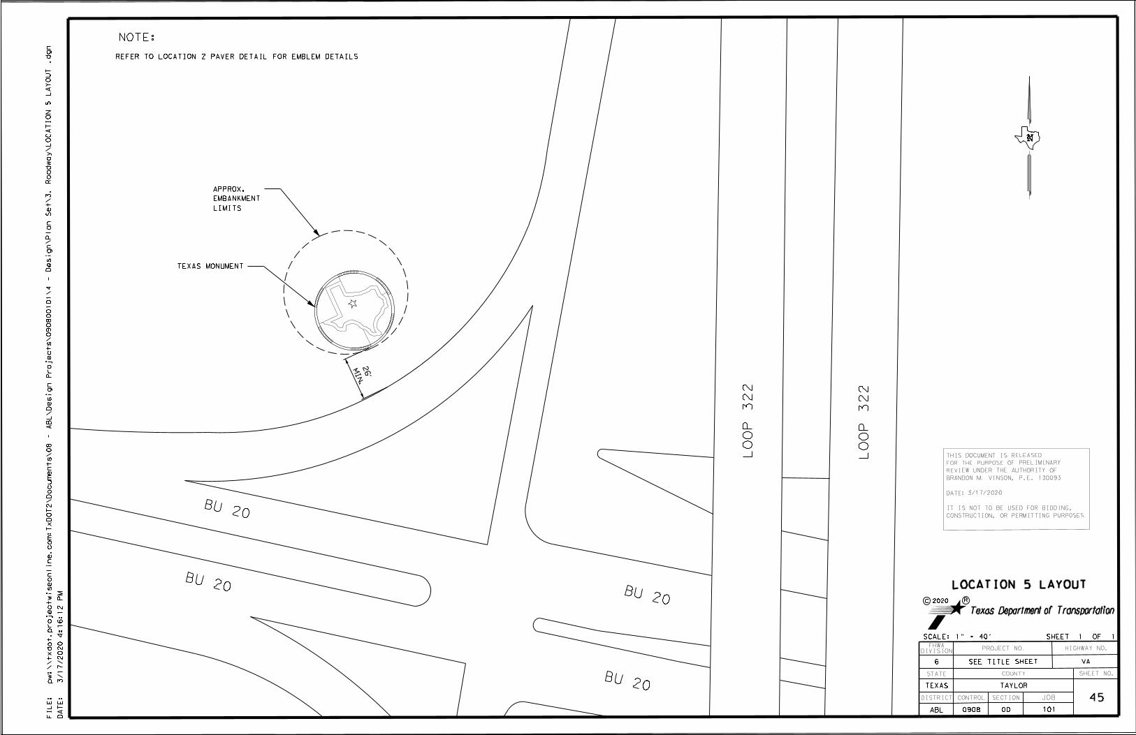
THIS DOCUMENT IS RELEASED
FOR THE PURPOSE OF PRELIMINARY
REVIEW UNDER THE AUTHORITY OF
BRANDON M. VINSON, P.E. 130093
IT IS NOT TO BE USED FOR BIDDING,
CONSTRUCTION, OR PERMITTING PURPOSES.
DATE: 3/17/2020
N
BU 20
BU 20
BU 20
BU 20
LO
OP 322
LO
OP 322
TEXAS MONUMENT
DA
TE:
FI
LE:
4:16:12
PM
3/17/2020
pw:\\txdot.project
wiseonline.co
m:
Tx
DO
T2\
Docu
ments\08 -
AB
L\
Design
Projects\090800101\4 -
Design\
Plan
Set\3.
Road
way\
LO
CA
TI
ON 5
LA
YO
UT .dgn
COUNTY
JOB
HIGHWAY NO.
TEXAS
DISTRICT SECTIONCONTROL
TAYLOR
0908 00 101
PROJECT NO.
6
ABL
DIVISION
FHWA
STATE SHEET NO.
45
VA
LOCATION 5 LAYOUT
SCALE: 1" = 40' SHEET 1 OF 1
SEE TITLE SHEET
C
Texas Department of Transportation
2020 R
MI
N.
26'
NOTE:
REFER TO LOCATION 2 PAVER DETAIL FOR EMBLEM DETAILS
LIMITS
EMBANKMENT
APPROX.

PAVER EMBLEM
DA
TE:
FI
LE:
4:16:19
PM
3/17/2020
pw:\\txdot.project
wiseonline.co
m:
Tx
DO
T2\
Docu
ments\08 -
AB
L\
Design
Projects\090800101\4 -
Design\
Plan
Set\9.
Environ
mental\
SW3
P
DE
TAI
LS.dgn
COUNTY
JOB
HIGHWAY NO.
TEXAS
DISTRICT SECTIONCONTROL
TAYLOR
0908 00 101
PROJECT NO.
6
ABL
DIVISION
FHWA
STATE SHEET NO.
46
VA
SW3P DETAILS
NO SCALE SHEET 1 OF 1
SEE TITLE SHEET
C
Texas Department of Transportation
2020 R
BRANDON M. VINSON, P.E. 130093
DATE:3/17/2020
THIS DOCUMENT IS RELEASED
FOR THE PURPOSE OF PRELIMINARY
REVIEW UNDER THE AUTHORITY OF
IT IS NOT TO BE USED FOR BIDDING,
CONSTRUCTION, OR PERMITTING PURPOSES.
LIMIT OF CONSTRUCTION/LANDSCAPING
OUTER CONCRETE RING
10'
ACTIVITIES
OUTSIDE OF CONSTRUCTION
NATIVE VEGATATIVE FILTER STRIP
MAINTAIN MINIMUM 10' EXISTING
NATIVE VEGETATIVE FILTER STRIP
TYPICAL FLOW DIRECTION
LEGEND
NOTES
GRASS WITH TEMP. SEED AS NECESSARY.
2) REPLACE FILTER STRIPS AND NATIVE
AS DIRECTED BY THE ENGINEER.
THE VICINITY OF EACH WORK LOCATION
1) LOCATE CONCRETE WASHOUTS WITHIN

PREVENTION PLAN (SW3P)
TxDOT STORM WATER POLLUTION
4:16:23
PM
3/17/2020
pw:\\txdot.project
wiseonline.co
m:
Tx
DO
T2\
Docu
ments\08 -
AB
L\
Design
Projects\090800101\4 -
Design\
Plan
Set\9.
Environ
mental\
SW3
P.dgn
SITE DESCRIPTION EROSION AND SEDIMENT CONTROLS
PROJECT LIMITS: USE "T" OR "P" IN THE BLANKS BELOW IF APPLICABLE (T= TEMPORARY, P= PERMANENT) OTHER EROSION AND SEDIMENT CONTROLS:THE PROJECT LIMITS SHOWN ON THE TITLE SHEET
AND LIMITS OF TXDOT RIGHT OF WAY SHALL ALSO SOIL STABILIZATION PRACTICES: MAINTENANCE:
BE THE LIMITS OF COVERAGE OF THE SW3P. ALL EROSION AND SEDIMENT CONTROLS WILL BE MAINTAINED IN GOOD WORKING ORDER.
BUFFER ZONES PERMANENT PLANTING, SODDING, OR SEEDING IF A REPAIR IS NECESSARY, IT WILL BE DONE AT THE EARLIEST DATE POSSIBLE, BUT
PROJECT LOCATION MAPS: TITLE SHEET MULCHING PRESERVATION OF NATURAL RESOURCES NO LATER THAN 7 CALENDAR DAYS AFTER THE SURROUNDING EXPOSED GROUND HAS DRIED
TEMPORARY SEEDING SOIL RETENTION BLANKET SUFFICIENTLY TO PREVENT FURTHER DAMAGE FROM HEAVY EQUIPMENT. THE AREAS
OTHER OTHER ADJACENT TO CREEKS AND DRAINAGE WAYS SHALL HAVE PRIORITY FOLLOWED BY DEVICES
PROTECTING STORM SEWER INLETS.
OTHER:
APPROX. SLOPES ANTICIPATED AFTER MAJOR GRADING DISTURBED AREAS ON WHICH CONSTRUCTION ACTIVITY HAS CEASED INSPECTION:
AND AREAS OF SOIL DISTURBANCE: TYPICAL (TEMPORARILY OR PERMANENTLY) SHALL BE STABILIZED WITHIN AN INSPECTION WILL BE PERFORMED BY A TXDOT INSPECTOR EVERY 7 DAYS. AN
SECTIONS 14 DAYS UNLESS ACTIVITIES ARE SCHEDULED TO RESUME WITHIN INSPECTION AND MAINTENANCE REPORT WILL BE MADE PER EACH INSPECTION. BASED ON
THE INSPECTION RESULTS, THE CONTROLS SHALL BE REVISED PER THE INSPECTION REPORT.
MAJOR CONTROLS AND LOCATIONS OF STABILIZATION
FOR CONSTRUCTION PROJECTS, THIS DISTRICT OF THE TEXAS DEPARTMENT OF WASTE MATERIALS:
TRANSPORTATION USES SITEMANAGER, A COMPUTER BASED CONSTRUCTION ALL WASTE MATERIALS WILL BE COLLECTED AND STORED IN A SECURELY LIDDED METAL
PROJECT SPECIFIC LOCATIONS: TO BE SPECIFIED BY RECORD-KEEPING SYSTEM, AS PART OF RECORD FOR PROJECT WORK INCLUDING DUMPSTER. THE DUMPSTER WILL MEET ALL STATE AND LOCAL CITY SOLID WASTE
PROJECT FIELD OFFICE AND LOCATED IN THE ENVIRONMENTAL RELATED ACTIVITIES. DOCUMENTATION DESCRIBING MAJOR MANAGEMENT REGULATIONS. ALL TRASH AND CONSTRUCTION DEBRIS FROM THE SITE WILL
PROJECT SW3P FILE. GRADING ACTIVITES, TEMPORARY OR PERMANENT CESSATION OF BE DEPOSITED IN THE DUMPSTER. THE DUMPSTER WILL BE EMPTIED AS NECESSARY OR AS
CONSTRUCTION AND STABILIZATION MEASURE IS PART OF THIS SYSTEM AND IS REQUIRED BY LOCAL REGULATION AND THE TRASH WILL BE HAULED TO A PERMITTED
SURFACE WATERS AND DISCHARGE LOCATIONS: INCORPORATED BY REFERENCE INTO THIS SW3P. LANDFILL. NO CONSTRUCTION WASTE MATERIAL WILL BE BURIED ON SITE.
CONSTRUCTION DEBRIS AND LITTER SHOULD BE PICKED UP ON A DAILY BASIS UNLESS
STRUCTURAL PRACTICES: OTHERWISE DIRECTED BY THE ENGINEER. WASTE AND DIRT PILES SHOULD BE REMOVED ON
A WEEKLY BASIS.
CHANNEL LINERS DIVERSION DIKE AND SWALE COMBINATIONS
CURBS AND GUTTERS DIVERSION, INTERCEPTOR, OR PERIMETER DIKES HAZARDOUS WASTE (INCLUDING SPILL REPORTING):
HAY BALES DIVERSION, INTERCEPTOR, OR PERIMETER SWALES NO LONG TERM WATER QUALITY IMPACTS ARE EXPECTED AS A RESULT OF THE PROPOSED
ENDANGERED SPECIES, DESIGNATED CRITICAL HABITAT PAVED FLUMES ROCK BEDDING AT CONSTRUCTION EXIT PROJECT. SEE THE NEXT PLAN SHEET FOR A LIST OF POTENTIAL POLLUTANTS. IN THE
AND HISTORIC PROPERTY: EPIC SHEET PIPE SLOPE DRAINS STONE OUTLET STRUCTURES EVENT OF A MAJOR SPILL, NOTIFY THE TXDOT ENGINEER IMMEDIATELY. ALL PERSONNEL
ROCK FILTER DAMS
STORM INLET SEDIMENT TRAP WILL BE INSTRUCTED IN THE PROCEDURES FOR SPILL HANDLING AND DISPOSING OF ANY
SEDIMENT BASINS TEMPORARY EROSION CONTROL LOGS (BIOLOGS) HAZARDOUS MATERIALS THEY WILL BE USING. ALL SPILLS, INCLUDING THOSE OF LESS
NATURE OF ACTIVITY:
SEDIMENT TRAPS TIMBER MATTING AT CONSTRUCTION EXIT THAN 25 GALLONS SHALL BE CLEANED IMMEDIATELY AND ANY CONTAMINATED SOIL SHALL
<PROJECT DESCRIPTION FROM TITLE SHEET>
SILT FENCES VEGETATIVE FILTER STRIPS BE IMMEDIATELY REMOVED FROM THE SITE AND BE DISPOSED OF PROPERLY. DESIGNATED
STORM SEWERS
VELOCITY CONTROL DEVICES AREAS SHALL BE DETERMINED BY THE AREA ENGINEER FOR SPOILS DISPOSAL AND
MATERIAL STORAGE. THESE AREAS SHALL BE PROTECTED FROM RUN-ON AND RUN-OFF.
MATERIALS RESULTING FROM THE DESTRUCTION OF EXISTING ROADS AND BEING REMOVED
MAJOR SOIL DISTURBING ACTIVITIES:
OFFSITE VEHICLE TRACKING CONTROLS: AND/OR DISPOSED OF BY THE CONTRACTOR WILL BE DONE SO IN ACCORDANCE WITH ALL
FEDERAL, STATE, AND LOCAL LAWS, ORDINANCES AND REGULATIONS AND WITH THE
HAUL ROADS DAMPENED FOR DUST CONTROL APPROVAL OF THE PROJECT ENGINEER. ANY CHANGES TO AMBIENT WATER QUALITY
EXCESS DIRT ON ROAD REMOVED DAILY DURING CONSTRUCTION OF THE PROPOSED PROJECT SHALL BE PROHIBITED AND MAY RESULT
LOADED HAUL TRUCKS TO BE COVERED WITH TARPAULIN IN ADDITIONAL WATER QUALITY CONTROL MEASURES, WHICH SHALL BE MITIGATED AS SOON
STABILIZED CONSTRUCTION ENTRANCE AS POSSIBLE AND SHALL BE REPORTED TO THE TEXAS COMMISSION ON ENVIRONMENTAL
TOTAL PROJECT AREA:
OTHER QUALITY (TCEQ) WITHIN 24 HOURS OF BECOMING AWARE OF IMPACTS.
NA
SANITARY WASTE:
TOTAL AREA TO BE DISTURBED (AT ALL SITES):
NARRATIVE - SEQUENCE OF CONSTRUCTION ALL SANITARY WASTE WILL BE COLLECTED FROM THE PORTABLE UNITS AS NECESSARY OR AS
0.44 ACRES
(STORM WATER MANAGEMENT) ACTIVITIES: REQUIRED BY LOCAL REGULATION BY A LICENSED SANITARY WASTE MANAGEMENT CONTRACTOR.
THE ORDER OF ACTIVITIES WILL BE AS FOLLOWS: REMARKS:
NA CONSTRUCTION STAGING AREAS AND VEHICLE MAINTENANCE AREAS SHALL BE CONSTRUCTED
BY THE CONTRACTOR IN A MANNER TO MINIMIZE THE RUNOFF OF POLLUTANTS.
ALL WATERWAYS SHALL BE CLEARED AS SOON AS PRACTICABLE OF TEMPORARY EMBANKMENT,
WEIGHTED RUNOFF COEFFICIENT BEFORE CONSTRUCTION: TEMPORARY BRIDGES, MATTING, FALSEWORK PILING, DEBRIS OR OTHER OBSTRUCTIONS
NA STORM WATER MANAGEMENT: PLACED DURING CONSTRUCTION OPERATIONS THAT ARE NOT PART OF THE FINISHED WORK.
NA DISPOSAL AREAS, STOCKPILES, AND HAUL ROADS SHALL BE CONSTRUCTED IN A MANNER
WEIGHTED RUNOFF COEFFICIENT AFTER CONSTRUCTION: THAT WILL MINIMIZE AND CONTROL THE AMOUNT OF SEDIMENT THAT MAY ENTER
NA RECEIVING WATERS. DISPOSAL AREAS SHALL NOT BE LOCATED IN ANY WETLAND,
WATER BODY OR STREAMBED.
EXISTING CONDITION OF SOIL & VEGETATIVE COVER:
NA
% OF EXISTING VEGETATIVE COVER:
NA
NAME OF RECEIVING WATERS:
IN THE INTENDED SCHEDULE/SEQUENCE OF EARTH-
ESTIMATE
DISTURBING ACTIVITIES: CONTRACT TIME
ESTIMATED START DATES AND DURATION OF ACTIVITIES
NO SCALE SHEET 1 OF 2
C
Texas Department of Transportation
2020 R
COUNTY
JOB
HIGHWAY NO.
TEXAS
DISTRICT SECTIONCONTROL
TAYLOR
0908 00 101
PROJECT NO.
6
ABL
DIVISION
FHWA
STATE SHEET NO.
47
VASEE TITLE SHEET
14 DAYS.
LINED CONCRETE WASHOUT
P
T
EROSION CONTROL LOGS
THIS DOCUMENT IS RELEASED
FOR THE PURPOSE OF PRELIMINARY
REVIEW UNDER THE AUTHORITY OF
IT IS NOT TO BE USED FOR BIDDING,
CONSTRUCTION, OR PERMITTING PURPOSES.
BRANDON M. VINSON, P.E. 130093
DATE: 3/17/2020
T
P
P
X
DRAINAGE PATTERNS: N/A
PRACTICES: N/A
N/A
TYPICAL AREAS WHICH WILL NOT BE DISTURBED: N/A
EMBANKMENT
CEDAR CREEK, 1236A-BRAZOS RIVER BASIN
X
T

PREVENTION PLAN (SW3P)
TxDOT STORM WATER POLLUTION
4:16:24
PM
3/17/2020
pw:\\txdot.project
wiseonline.co
m:
Tx
DO
T2\
Docu
ments\08 -
AB
L\
Design
Projects\090800101\4 -
Design\
Plan
Set\9.
Environ
mental\
SW3
P.dgn
REV. DATE: 02/27/2014
POLLUTANTS POTENTIAL OFLIST
POLLUTANTPOTENTIAL SOURCERELATED CONTROLS
CONCRETE)
(BROKEN AGGREGATES CEMENTATEOUS AND MATERIALCEMENTATEOUS
ETC.COMPONENTS,
BRIDGE COMPONENTS, CULVERT RIPRAP, CONCRETE OFREMOVAL
RUNOFF. SURFACE ENTER CANNOT IT THAT ENSURE TO AS SO CONTAINED BE SHALL IT DISPOSAL, TO PRIOR SITE ONSTORED
WHEN REGULATIONS. LOCAL AND STATE WITH ACCORDANCE IN OF DISPOSED PROPERLY BE SHALL WASTE CONSTRUCTIONTHIS
(MILLINGS) PAVEMENT CEMENT ASPHALTICMILLED ASPHALT OF PLANING AND ROAD ABANDONED OFOBLITERATION RUNOFF. SURFACE ENTER CANNOT IT THAT ENSURE TO AS SO CONTAINED BE SHALL IT DISPOSAL, TO PRIOR SITE ONSTORED
WHEN REGULATIONS. LOCAL AND STATE WITH ACCORDANCE IN OF DISPOSED PROPERLY BE SHALL WASTE CONSTRUCTIONTHIS
MIXTURES BITUMINOUS MIX HOT ANDAGGREGATES,
PRECOAT OILS, PRIME OF INCLUSIVE MATERIAL ASPHALTICVIRGIN
OPERATIONS
PAVING AND COAT, SEAL COATS, PRIME OFAPPLICATIONS
NOTIFIED. IMMEDIATELY BE WILL TCEQ AND PLACEDIMMEDIATELY
BE WILL RUNOFF CONTAIN TO CONTROLS DISCHARGE, UNINTENDED ANY OF EVENT THE IN RUNOFF. ENTERING FROMMATERIALS
THESE PRECLUDE WILL WHICH PURPOSES CONSTRUCTION FOR RATES APPROPRIATE AT APPLIED BE SHALL MATERIALTHIS
OIL LINSEED AND COMPOUND CURING FIBERBOARD,BLOCK,
STYROFOAM NAILS, LUMBER, FABRIC WIRE WIRE, REBAR,CONCRETE,
FOUNDATIONS SIGN AND RIPRAPGUTTER,
AND CURB BARRIERS, TRAFFIC CONCRETE INLET, RAIL,SLABS,
CONCRETE REINFORCED BENTS, ABUTMENTS, CULVERTS,SHAFTS,
DRILLED AS SUCH COMPONENTS BRIDGE CONCRETE OFCONSTRUCTION
CONDITION/ELEVATION.
PREEXISTING THEIR TO RETURNED AREAS AFFECTED THE AND ENTIRETY THEIR IN REMOVED BE MUST FILLS TEMPORARYANY
RUNOFF. SURFACE ENTER CANNOT IT THAT ENSURE TO AS SO CONTAINED BE SHALL IT DISPOSAL, TO PRIOR SITE ONSTORED
WHEN REGULATIONS. LOCAL AND STATE WITH ACCORDANCE IN OF DISPOSED PROPERLY BE SHALL WASTE CONSTRUCTIONTHIS
RAPPLASTIC
AND CARDBOARD, FABRIC, GEOGRID BLOCK, CONCRETEMASONRY SYSTEMS WALL RETAINING MODULAR OFCONSTRUCTION
RUNOFF. SURFACE ENTER CANNOT IT THAT ENSURE TO AS SO CONTAINED BE SHALL IT DISPOSAL, TO PRIOR SITE ONSTORED
WHEN REGULATIONS. LOCAL AND STATE WITH ACCORDANCE IN OF DISPOSED PROPERLY BE SHALL WASTE CONSTRUCTIONTHIS
WASHERS AND BOLTS, NUTS, FASTENERS, PLYBOARD), AND(ALUMINUM
BOARDS SIGN CONES, BARRELS, POSTS, STEEL POSTS,WOOD
DEVICESCONTROL
TRAFFIC AND SIGNS BARRICADES, OF REMOVAL AND/ORPLACEMENT
RUNOFF. SURFACE ENTER CANNOT IT THAT ENSURE TO AS SO CONTAINED BE SHALL IT DISPOSAL, TO PRIOR SITE ONSTORED
WHEN REGULATIONS. LOCAL AND STATE WITH ACCORDANCE IN OF DISPOSED PROPERLY BE SHALL WASTE CONSTRUCTIONTHIS
WASHERS
AND BOLTS, NUTS, FASTENERS, STEEL POST, STEEL POST,WOOD FENCE GUARD BEAM METAL OFCONSTRUCTION
RUNOFF. SURFACE ENTER CANNOT IT THAT ENSURE TO AS SO CONTAINED BE SHALL IT DISPOSAL, TO PRIOR SITE ONSTORED
WHEN REGULATIONS. LOCAL AND STATE WITH ACCORDANCE IN OF DISPOSED PROPERLY BE SHALL WASTE CONSTRUCTIONTHIS
FOUNDATIONS
CONCRETE AND BOARDS, SIGN I-BEAM, STEELSTRUCTURAL SMALL AND LARGE ASSEMBLIES SIGN ROADSIDE OFREMOVAL
RUNOFF. SURFACE ENTER CANNOT IT THAT ENSURE TO AS SO CONTAINED BE SHALL IT DISPOSAL, TO PRIOR SITE ONSTORED
WHEN REGULATIONS. LOCAL AND STATE WITH ACCORDANCE IN OF DISPOSED PROPERLY BE SHALL WASTE CONSTRUCTIONTHIS
MARKERS PAVEMENT REFLECTIVERAISED
AND TABS, REFLECTIVE BEADS, GLASS PAINT,THERMOPLASTIC MARKINGS/MARKERS PAVEMENT OFAPPLICATION
RUNOFF. SURFACE ENTER CANNOT IT THAT ENSURE TO AS SO CONTAINED BE SHALL IT DISPOSAL, TO PRIOR SITE ONSTORED
WHEN REGULATIONS. LOCAL AND STATE WITH ACCORDANCE IN OF DISPOSED PROPERLY BE SHALL WASTE CONSTRUCTIONTHIS
CONTRACTOR)
BY INTRODUCED QUANTITIES (SMALL PRODUCTSPETROLEUM REPAIR AND MAINTENANCE FAILURE,EQUIPMENT
REGULATIONS. MANAGEMENT WASTE LOCAL AND STATE ALL MEETING COVER SECURE A WITHCONTAINER
A IN CONTAINED BE SHALL DISPOSAL TO PRIOR STORED MATERIAL ALL REGULATIONS. MANAGEMENT WASTE LOCAL ANDSTATE
ACCORDANCE IN LIQUIDS OTHER AND OIL HYDRAULIC INCLUDING MATERIALS WASTE ALL OF DISPOSAL PROPER ANDCONTAINMENT
FOR MEASURES APPROPRIATE WITH AREA DESIGNATED A IN PERFORMED BE SHALL MAINTENANCE VEHICLE AND EQUIPMENTALL
DISCHARGE WATER NON-STORM AND WATER NON-POTABLE TOLIMITED
NOT BUT INCLUDING DISCHARGES WATER NON-STORMELIGIBLE
CONDENSATECONDITIONING
AIR AND WASHING, VEHICLE NON-DETERGENTWATERING,
VEGETATION DENSITY, CONTROL, DUST FOR APPLICATIONSMOISTURE
REUSE. FOR STORED PROPERLY AND RECOVERED BE WILL WATER NON-POTABLE THE AND PLACEDIMMEDIATELY
BE WILL RUNOFF CONTAIN TO CONTROLS DISCHARGE, UNINTENDED ANY OF EVENT THE IN RUNOFF. ENTERING FROMMATERIALS
THESE PRECLUDE WILL WHICH PURPOSES CONSTRUCTION FOR RATES APPROPRIATE AT APPLIED BE SHALL MATERIALTHIS
PAINT AND TAPE FLAGGING STAKE,SURVEY ESTABLISHMENT ALIGNMENT STAKING,SURVEY RUNOFF. SURFACE ENTER CANNOT IT THAT ENSURE TO AS SO CONTAINED BE SHALL IT DISPOSAL, TO PRIOR SITE ONSTORED
WHEN REGULATIONS. LOCAL AND STATE WITH ACCORDANCE IN OF DISPOSED PROPERLY BE SHALL WASTE CONSTRUCTIONTHIS
WASTEWATER MATERIALS CONSTRUCTION OTHER AND COMPOUNDSCURING
OILS, RELEASE FORM PAINT, STUCCO, OF CLEANOUT ANDWASHOUT
RUNOFF. SURFACE ENTER CANNOT IT THAT ENSURE TO AS SO CONTAINED BE SHALL IT DISPOSAL, TO PRIOR SITE ONSTORED
WHEN REGULATIONS. LOCAL AND STATE WITH ACCORDANCE IN OF DISPOSED PROPERLY BE SHALL WASTE CONSTRUCTIONTHIS
SOLVENTS ANDSOAPS WASHING EQUIPMENT ANDVEHICLE RUNOFF. SURFACE ENTER CANNOT IT THAT ENSURE TO AS SO CONTAINED BE SHALL IT DISPOSAL, TO PRIOR SITE ONSTORED
WHEN REGULATIONS. LOCAL AND STATE WITH ACCORDANCE IN OF DISPOSED PROPERLY BE SHALL WASTE CONSTRUCTIONTHIS
MATERIAL FILLUNSUITABLE CONTROL EROSION AND SPECIAL ROADWAY, -EXCAVATION RUNOFF. SURFACE ENTER CANNOT IT THAT ENSURE TO AS SO CONTAINED BE SHALL IT DISPOSAL, TO PRIOR SITE ONSTORED
WHEN REGULATIONS. LOCAL AND STATE WITH ACCORDANCE IN OF DISPOSED PROPERLY BE SHALL WASTE CONSTRUCTIONTHIS
NO SCALE SHEET 2 OF 2
C
Texas Department of Transportation
2020 R
COUNTY
JOB
HIGHWAY NO.
TEXAS
DISTRICT SECTIONCONTROL
TAYLOR
0908 00 101
PROJECT NO.
6
ABL
DIVISION
FHWA
STATE SHEET NO.
48
VASEE TITLE SHEET
THIS DOCUMENT IS RELEASED
FOR THE PURPOSE OF PRELIMINARY
REVIEW UNDER THE AUTHORITY OF
IT IS NOT TO BE USED FOR BIDDING,
CONSTRUCTION, OR PERMITTING PURPOSES.
BRANDON M. VINSON, P.E. 130093
DATE: 3/17/2020
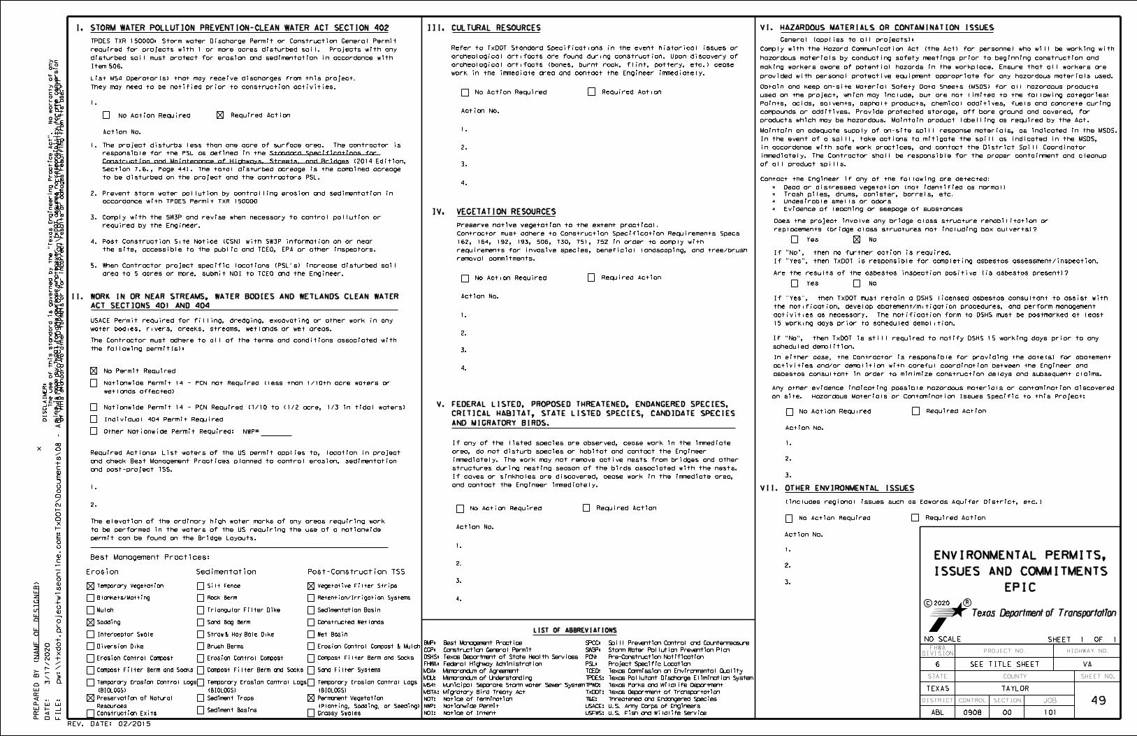
REV. DATE: 02/2015
)N
AM
E
OF
DE
SI
GN
ER
PR
EP
AR
ED
BY (
FI
LE:
DA
TE:
of this standard to other for
mats or for incorrect results or da
mages resulting fro
m its use.
kind is
made by
Tx
DO
T for any purpose
whatsoever.
Tx
DO
T assu
mes no responsibility for the conversion
The use of this standard is governed by the "
Texas
Engineering
Practice
Act".
No
warranty of any
DI
SC
LAI
ME
R:
1.
2.
ACT SECTIONS 401 AND 404
II. WORK IN OR NEAR STREAMS, WATER BODIES AND WETLANDS CLEAN WATER
They may need to be notified prior to construction activities.
List MS4 Operator(s) that may receive discharges from this project.
permit can be found on the Bridge Layouts.
to be performed in the waters of the US requiring the use of a nationwide
The elevation of the ordinary high water marks of any areas requiring work
and post-project TSS.
and check Best Management Practices planned to control erosion, sedimentation
Required Actions: List waters of the US permit applies to, location in project
Action No.
III. CULTURAL RESOURCES
work in the immediate area and contact the Engineer immediately.
archeological artifacts (bones, burnt rock, flint, pottery, etc.) cease
archeological artifacts are found during construction. Upon discovery of
Refer to TxDOT Standard Specifications in the event historical issues or
water bodies, rivers, creeks, streams, wetlands or wet areas.
USACE Permit required for filling, dredging, excavating or other work in any
the following permit(s):
The Contractor must adhere to all of the terms and conditions associated with
VI. HAZARDOUS MATERIALS OR CONTAMINATION ISSUES
General (applies to all projects):
LIST OF ABBREVIATIONS
IV. VEGETATION RESOURCES
No Action Required Required Action
Action No.
1.
2.
3.
4.
15 working days prior to scheduled demolition.
activities as necessary. The notification form to DSHS must be postmarked at least
the notification, develop abatement/mitigation procedures, and perform management
If "Yes", then TxDOT must retain a DSHS licensed asbestos consultant to assist with
If "Yes", then TxDOT is responsible for completing asbestos assessment/inspection.
If "No", then no further action is required.
products which may be hazardous. Maintain product labelling as required by the Act.
compounds or additives. Provide protected storage, off bare ground and covered, for
Paints, acids, solvents, asphalt products, chemical additives, fuels and concrete curing
used on the project, which may include, but are not limited to the following categories:
Obtain and keep on-site Material Safety Data Sheets (MSDS) for all hazardous products
Contact the Engineer if any of the following are detected:
* Evidence of leaching or seepage of substances
* Undesirable smells or odors
* Trash piles, drums, canister, barrels, etc.
* Dead or distressed vegetation (not identified as normal)
replacements (bridge class structures not including box culverts)?
Does the project involve any bridge class structure rehabilitation or
Yes No
(includes regional issues such as Edwards Aquifer District, etc.)
Action No.
1.
2.
3.
No Action Required Required Action
Are the results of the asbestos inspection positive (is asbestos present)?
Yes No
VII. OTHER ENVIRONMENTAL ISSUES
provided with personal protective equipment appropriate for any hazardous materials used.
making workers aware of potential hazards in the workplace. Ensure that all workers are
hazardous materials by conducting safety meetings prior to beginning construction and
Comply with the Hazard Communication Act (the Act) for personnel who will be working with
of all product spills.
immediately. The Contractor shall be responsible for the proper containment and cleanup
in accordance with safe work practices, and contact the District Spill Coordinator
In the event of a spill, take actions to mitigate the spill as indicated in the MSDS,
Maintain an adequate supply of on-site spill response materials, as indicated in the MSDS.
Action No.
1.
2.
3.
No Action Required Required Action
on site. Hazardous Materials or Contamination Issues Specific to this Project:
Any other evidence indicating possible hazardous materials or contamination discovered
scheduled demolition.
If "No", then TxDOT is still required to notify DSHS 15 working days prior to any
asbestos consultant in order to minimize construction delays and subsequent claims.
activities and/or demolition with careful coordination between the Engineer and
In either case, the Contractor is responsible for providing the date(s) for abatement
USFWS: U.S. Fish and Wildlife Service
USACE: U.S. Army Corps of Engineers
T&E: Threatened and Endangered Species
TxDOT: Texas Department of Transportation
TPWD: Texas Parks and Wildlife Department
TPDES: Texas Pollutant Discharge Elimination System
TCEQ: Texas Commission on Environmental Quality
PSL: Project Specific Location
PCN: Pre-Construction Notification
SW3P: Storm Water Pollution Prevention Plan
SPCC: Spill Prevention Control and Countermeasure
NOI: Notice of Intent
NWP: Nationwide Permit
NOT: Notice of Termination
MBTA: Migratory Bird Treaty Act
MS4: Municipal Separate Storm water Sewer System
MOU: Memorandum of Understanding
MOA: Memorandum of Agreement
FHWA: Federal Highway Administration
DSHS: Texas Department of State Health Services
CGP: Construction General Permit
BMP: Best Management Practice
pw:\\txdot.project
wiseonline.co
m:
Tx
DO
T2\
Docu
ments\08 -
AB
L\
Design
Projects\090800101\4 -
Design\
Plan
Set\9.
Environ
mental\
EPI
C.dgn
3/17/2020
x
Temporary Vegetation
Blankets/Matting
Mulch
Sodding
Interceptor Swale
Diversion Dike
Erosion Control Compost Erosion Control Compost
Silt Fence
Rock Berm
Triangular Filter Dike
Sand Bag Berm
Brush Berms
Sediment Basins
Vegetative Filter Strips
Retention/Irrigation Systems
Constructed Wetlands
Wet Basin
Sand Filter Systems
Best Management Practices:
Erosion Sedimentation Post-Construction TSS
Resources
Preservation of Natural
Sedimentation Basin
Compost Filter Berm and Socks
Construction Exits
& Hay Bale DikeStraw
Compost Filter Berm and Socks
Sediment Traps
(BIOLOGS)
Temporary Erosion Control Logs
Erosion Control Compost & Mulch
Compost Filter Berm and Socks
(BIOLOGS)
Temporary Erosion Control Logs
Vegetation
(Planting, Sodding, or Seeding)
Permanent
I. STORM WATER POLLUTION PREVENTION-CLEAN WATER ACT SECTION 402
No Action Required Required Action
1.
No Permit Required
Nationwide Permit 14 - PCN Required (1/10 to <1/2 acre, 1/3 in tidal waters)
Individual 404 Permit Required
Other Nationwide Permit Required: NWP#
wetlands affected)
Nationwide Permit 14 - PCN not Required (less than 1/10th acre waters or
NO SCALE SHEET 1 OF 1
COUNTY
JOB
HIGHWAY NO.
TEXAS
DISTRICT SECTIONCONTROL
TAYLOR
0908 00 101
PROJECT NO.
6
ABL
DIVISION
FHWA
STATE SHEET NO.
49
VASEE TITLE SHEET
C
Texas Department of Transportation
2020 R
Preserve native vegetation to the extent practical.Preserve native vegetation to the extent practical.
removal commitments.
requirements for invasive species, beneficial landscaping, and tree/brush
162, 164, 192, 193, 506, 730, 751, 752 in order to comply with
Contractor must adhere to Construction Specification Requirements Specs
and contact the Engineer immediately.
If caves or sinkholes are discovered, cease work in the immediate area,
structures during nesting season of the birds associated with the nests.
immediately. The work may not remove active nests from bridges and other
area, do not disturb species or habitat and contact the Engineer
If any of the listed species are observed, cease work in the immediate
AND MIGRATORY BIRDS.
CRITICAL HABITAT, STATE LISTED SPECIES, CANDIDATE SPECIES
V. FEDERAL LISTED, PROPOSED THREATENED, ENDANGERED SPECIES,
No Action Required Required Action
Action No.
1.
2.
3.
4.
No Action Required Required Action
Action No.
1.
2.
3.
4.
7.6., Page 44
2014
area to 5 acres or more, submit NOI to TCEQ and the Engineer.
5. When Contractor project specific locations (PSL's) increase disturbed soil
the site, accessible to the public and TCEQ, EPA or other inspectors.
4. Post Construction Site Notice (CSN) with SW3P information on or near
required by the Engineer.
3. Comply with the SW3P and revise when necessary to control pollution or
accordance with TPDES Permit TXR 150000
2. Prevent storm water pollution by controlling erosion and sedimentation in
to be disturbed on the project and the contractors PSL.
). The total disturbed acreage is the combined acreage Section
Edition, (Construction and Maintenance of Highways, Streets, and Bridges
Standard Specifications for responsible for the PSL as defined in the
1. The project disturbs less than one acre of surface area. The contractor is
506.Item
disturbed soil must protect for erosion and sedimentation in accordance with
required for projects with 1 or more acres disturbed soil. Projects with any
TPDES TXR 150000: Storm water Discharge Permit or Construction General Permit
ISSUES AND COMMITMENTS
ENVIRONMENTAL PERMITS,
EPIC
Grassy Swales
(BIOLOGS)
Temporary Erosion Control Logs