Embed Size (px)
Citation preview

e t h e r n e tn e t w o r k s
F o u r t h E d i t i o n
♦ Design♦ Implementation♦ Operation♦ Management
GILBERT HELD
4-Degree Consulting, Macon, Georgia, USA


e t h e r n e tn e t w o r k s
F o u r t h E d i t i o n

Books by Gilbert Held, published by Wiley
Quality of Service in a Cisco Networking Environment0 470 84425 6 (April 2002)
Bulletproofing TCP/IP-Based Windows NT/2000 Networks0 471 49507 7 (April 2001)
Understanding Data Communications: From Fundamentals to Networking,Third Edition0 471 62745 3 (October 2000)
High Speed Digital Transmission Networking: Covering T/E-CarrierMultiplexing, SONET and SDH, Second Edition0 471 98358 6 (April 1999)
Data Communications Networking Devices: Operation, Utilization and LANand WAN Internetworking, Fourth Edition0 471 97515 X (November 1998)
Dictionary of Communications Technology: Terms, Definitions andAbbreviations, Third Edition0 471 97517 6 (May 1998)
Internetworking LANs and WANs: Concepts, Techniques and Methods,Second Edition0 471 97514 1 (May 1998)
LAN Management with SNMP and RMON0 471 14736 2 (September 1996)

e t h e r n e tn e t w o r k s
F o u r t h E d i t i o n
♦ Design♦ Implementation♦ Operation♦ Management
GILBERT HELD
4-Degree Consulting, Macon, Georgia, USA

Copyright 2003 John Wiley & Sons Ltd, The Atrium, Southern Gate, Chichester,West Sussex PO19 8SQ, England
Telephone (+44) 1243 779777
Email (for orders and customer service enquiries): [email protected] our Home Page on www.wileyeurope.com or www.wiley.com
All Rights Reserved. No part of this publication may be reproduced, stored in a retrievalsystem or transmitted in any form or by any means, electronic, mechanical, photocopying,recording, scanning or otherwise, except under the terms of the Copyright, Designs andPatents Act 1988 or under the terms of a licence issued by the Copyright Licensing AgencyLtd, 90 Tottenham Court Road, London W1T 4LP, UK, without the permission in writing ofthe Publisher. Requests to the Publisher should be addressed to the Permissions Department,John Wiley & Sons Ltd, The Atrium, Southern Gate, Chichester, West Sussex PO19 8SQ,England, or emailed to [email protected], or faxed to (+44) 1243 770571.
This publication is designed to provide accurate and authoritative information in regard tothe subject matter covered. It is sold on the understanding that the Publisher is not engagedin rendering professional services. If professional advice or other expert assistance isrequired, the services of a competent professional should be sought.
Other Wiley Editorial Offices
John Wiley & Sons Inc., 111 River Street, Hoboken, NJ 07030, USA
Jossey-Bass, 989 Market Street, San Francisco, CA 94103-1741, USA
Wiley-VCH Verlag GmbH, Boschstr. 12, D-69469 Weinheim, Germany
John Wiley & Sons Australia Ltd, 33 Park Road, Milton, Queensland 4064, Australia
John Wiley & Sons (Asia) Pte Ltd, 2 Clementi Loop #02-01, Jin Xing Distripark,Singapore 129809
John Wiley & Sons Canada Ltd, 22 Worcester Road, Etobicoke, Ontario, Canada M9W 1L1
British Library Cataloguing in Publication Data
A catalogue record for this book is available from the British Library
ISBN 0-470-84476-0
Typeset in 10.5/13pt Melior by Laserwords Private Limited, Chennai, IndiaPrinted and bound in Great Britain by Biddles Ltd, Guildford and King’s LynnThis book is printed on acid-free paper responsibly manufactured from sustainable forestryin which at least two trees are planted for each one used for paper production.

For the past decade I have been most fortunate in being able to teach graduatecourses that were truly enjoyable to teach. In doing so I have been able totailor my presentation of technical information covering LAN performanceand other data communications topics, providing a two-way learning facilityand enhancing my presentation skills. Thus, I would be remiss if I did notthank the students at Georgia College and State University as well as Dr HarveyGlover for providing me with the opportunity to teach. In doing so I wouldlike to dedicate this book to those who pursue higher education.


c o n t e n t s
Preface xv
Acknowledgments xix
Chapter 1 Introduction to Networking Concepts 1
1.1 WIDE AREA NETWORKS 2COMPUTER-COMMUNICATIONS EVOLUTION 2REMOTE BATCH TRANSMISSION
3270 INFORMATION DISPLAY SYSTEMNETWORK CONSTRUCTION 5NETWORK CHARACTERISTICS 8
1.2 LOCAL AREA NETWORKS 8COMPARISON TO WANS 9TECHNOLOGICAL CHARACTERISTICSTRANSMISSION MEDIUM 22ACCESS METHOD 29
1.3 WHY ETHERNET
Chapter 2 Networking Standards 37
2.1 STANDARDS ORGANIZATIONS 37NATIONAL STANDARDS ORGANIZATIONS 38INTERNATIONAL STANDARDS ORGANIZATIONS 39
2.2 THE ISO REFERENCE MODEL
LAYERED ARCHITECTURE 41OSI LAYERS 42DATA FLOW 46
vii
3IBM
14
4
34
41

viii c o n t e n t s
2.3 IEEE 802 STANDARDS 48802 COMMITTEES 48DATA LINK SUBDIVISION 51
2.4 INTERNET STANDARDS 55RFC EVOLUTION 56TYPES AND SUBMISSION 56OBTAINING RFCS 57
2.5 CABLING STANDARDS
EIA/TIA-568 58UTP CATEGORIES 59CABLE SPECIFICATIONS 60OTHER METRICS 61CAT 5E AND CAT 6 63
Chapter 3 Ethernet Networks 65
3.1 ETHERNET 65EVOLUTION 66NETWORK COMPONENTS
THE 5-4-3 RULE
3.2 IEEE 802.3 NETWORKS 74NETWORK NAMES 7410BASE-5 7510BASE-2 7910BROAD-36 871BASE-5 8910BASE-T
3.3 USE OF FIBER-OPTIC TECHNOLOGY 100FOIRLOPTICAL TRANSCEIVER
FIBER HUBS 101FIBER ADAPTER 102WIRE AND FIBER DISTANCE LIMITS 102
3.4 HIGH-SPEED ETHERNET 108ISOCHRONOUS ETHERNET 108FAST ETHERNET
100VG-ANYLAN 133
58
673
7
9
101
1
101
111

contents ix
3.5 GIGABIT ETHERNET 138COMPONENTS 138MEDIA SUPPORT 141
3.6 10 GIGABIT ETHERNET 149RATIONALE 149ARCHITECTURE 150OPERATING RATES 153
Chapter 4 Frame Operations 155
4.1 FRAME COMPOSITION
PREAMBLE FIELD
START-OF-FRAME DELIMITER FIELD 157DESTINATION ADDRESS FIELD 157SOURCE ADDRESS FIELD
TYPE FIELD
LENGTH FIELD 166DATA FIELD 168FRAME CHECK SEQUENCE FIELD 168INTERFRAME GAP 169
4.2 MEDIA ACCESS CONTROL 169TRANSMIT MEDIA ACCESS MANAGEMENT
SERVICE PRIMITIVES 175PRIMITIVE OPERATIONS
HALF- VERSUS FULL-DUPLEX OPERATION
4.3 LOGICAL LINK CONTROL 177TYPES AND CLASSES OF SERVICE 179SERVICE PRIMITIVES 181
4.4 OTHER ETHERNET FRAME TYPES 181ETHERNET-802.3 181ETHERNET-SNAPIEEE 802.1Q FRAME 183FRAME DETERMINATION 184
4.5 FAST ETHERNET 185START-OF-STREAM DELIMITER 186END-OF-STREAM DELIMITER 186
157
160
155
165
182
172
176176

x c o n t e n t s
4.6 GIGABIT ETHERNET 186CARRIER EXTENSION
FRAME BURSTING 1894.7 10 GIGABIT ETHERNET 190
Chapter 5 Networking Hardware and Software 191
5.1 WIRED NETWORK HARDWARE COMPONENTS 192REPEATERS 192BRIDGES 195ROUTERS 205BROUTERS 210GATEWAY
FILE SERVERS 214WIRE HUBS 218INTELLIGENT HUBS 219SWITCHING HUBS 219
5.2 WIRELESS NETWORK HARDWARE COMPONENTS 221NETWORK TOPOLOGIES 221ACCESS POINT
WIRELESS ROUTER 222WIRELESS BRIDGE 223
5.3 NETWORKING SOFTWARE 224DOS 224NETWORK SOFTWARE COMPONENTS 225NETWORK OPERATING SYSTEMS
APPLICATION SOFTWARE
5.4 THE TCP/IP PROTOCOL SUITE
OVERVIEW 244PROTOCOL DEVELOPMENT 244THE TCP/IP STRUCTURE 245DATAGRAMS VERSUS VIRTUAL CIRCUITS 247ICMP 249ARP 252TCP 254UDP 259IP 260
227
187
213
222
243244

contents xi
DOMAIN NAME SERVICE 269NAME SERVER 272TCP/IP CONFIGURATION 272OPERATING MULTIPLE STACKS
Chapter 6 Bridging and Switching Methods and PerformanceIssues 279
6.1 BRIDGING METHODS 279ADDRESS ISSUES 280TRANSPARENT BRIDGING 280SPANNING TREE PROTOCOL 283PROTOCOL DEPENDENCY 291SOURCE ROUTING 292SOURCE ROUTING TRANSPARENT BRIDGES 297
6.2 BRIDGE NETWORK UTILIZATION 299SERIAL AND SEQUENTIAL BRIDGING 300PARALLEL BRIDGING 301STAR BRIDGING 302BACKBONE BRIDGING 302
6.3 BRIDGE PERFORMANCE ISSUES
TRAFFIC FLOW
NETWORK TYPES 304TYPE OF BRIDGE 304ESTIMATING NETWORK TRAFFIC 304PREDICTING THROUGHPUT
6.4 LAN SWITCHES 312RATIONALE
BOTTLENECKS 314CONGESTION-AVOIDANCE OPTIONS 314LAN SWITCH OPERATIONS 318
6.5 SWITCH BASIC ARCHITECTURE 332COMPONENTS 332
SWITCHED-BASED VIRTUAL LANS 348SWITCH USAGE 360LAYER 3 AND LAYER 4 SWITCHING 364
313
303
311
SWITCH FEATURES 33
275
5
303

xii c o n t e n t s
Chapter 7 Routers 365
7.1 ROUTER OPERATION 365IP SUPPORT OVERVIEW 365BASIC OPERATION AND USE OF ROUTING TABLES 368NETWORKING CAPABILITY 370
7.2 COMMUNICATION, TRANSPORT, AND ROUTING PROTOCOLS 371COMMUNICATION PROTOCOL 371ROUTING PROTOCOL
HANDLING NONROUTABLE PROTOCOLS 372TRANSPORT PROTOCOL 373
7.3 ROUTER CLASSIFICATIONS 374PROTOCOL-DEPENDENT ROUTERS 374PROTOCOL-INDEPENDENT ROUTERS 377
7.4 ROUTING PROTOCOLS 381TYPES OF ROUTING PROTOCOLS 381INTERIOR DOMAIN ROUTING PROTOCOLS 381EXTERIOR DOMAIN ROUTING PROTOCOLS 382
ROUTING INFORMATION PROTOCOL 386CONFIGURATION EXAMPLE 389ROUTING TABLE MAINTENANCE PROTOCOL 392INTERIOR GATEWAY ROUTING PROTOCOL 393LINK STATE PROTOCOLS
7.5 FILTERING
FILTERING EXPRESSIONS
FILTERING EXAMPLES 401ROUTER ACCESS LISTS 402
7.6 PERFORMANCE CONSIDERATIONS 404
Chapter 8 Wireless Ethernet 407
8.1 OVERVIEW 407NETWORK TOPOLOGY 409ROAMING 411PHYSICAL LAYER OPERATIONS 412HIGH-SPEED WIRELESS LANS 415ACCESS METHOD 418
372
TYPES OF INTERIOR DOMAIN ROUTING PROTOCOLS 38
394
4
399401

contents xiii
8.2 FRAME FORMATS
DATA FRAME 421CONTROL FIELD 422CONTROL FRAMES 428MANAGEMENT FRAMES
PHYSICAL PROTOCOL DATA UNITS 4328.3 DEPLOYMENT 434
WIRELESS PC NETWORK ADAPTER CARDS 434ACCESS POINT
COMBINED ROUTER/ACCESS POINT
WIRELESS BRIDGE 439ROUTER/ACCESS POINT CONFIGURATION 439CLIENT CONFIGURATION 441
Chapter 9 Security 447
9.1 THE SECURITY ROLE OF THE ROUTER
ACCESS CONTROL 448ACCESS LISTS 457STANDARD IP ACCESS LISTS
EXTENDED IP ACCESS LISTS 462ANTI-SPOOFING STATEMENTS 471NAMED ACCESS LISTS 472DYNAMIC ACCESS LISTS
REFLEXIVE ACCESS LISTS 478TIME-BASED ACCESS LISTS 482CONTEXT BASED ACCESS CONTROL 483
9.2 THE ROLE OF THE FIREWALL 494ACCESS-LIST LIMITATIONS 494PROXY SERVICES 496FIREWALL LOCATION 498THE TECHNOLOGIC INTERCEPTOR 504CHECKPOINT FIREWALL-1 510
9.3 THE ROLE OF THE VIRUS SCANNER
AND ENCRYPTION 516VIRUS OVERVIEW 516TYPES OF VIRUSES 517INFECTION PREVENTION
421
430
43
447
7435
475
459
519

xiv c o n t e n t s
DESKTOP SCANNING
EMAIL SCANNING
RECOGNIZING INFECTION SYMPTOMS 528
Chapter 10 Managing the Network 531
10.1 SNMP 531BASIC COMPONENTS 532OPERATION
10.2 REMOTE MONITORING 535OPERATION 535THE RMON MIB 536MANAGING REMOTE NETWORKS 539
10.3 OTHER NETWORK MANAGEMENT FUNCTIONS 541CONFIGURATION MANAGEMENT 542PERFORMANCE MANAGEMENT 543FAULT MANAGEMENT 543ACCOUNTING MANAGEMENT
SECURITY MANAGEMENT 54410.4 REPRESENTATIVE NETWORK MANAGEMENT PROGRAMS
TRITICOM ETHERVISION 545CINCO NETWORK’S WEBXRAY 554WILDPACKETS ETHERPEEK 559
Chapter 11 The Future of Ethernet 567
11.1 ETHERNET TRENDS 567NETWORK ADAPTER CARD COST 567FUTURE PRICE DIRECTION 568
11.2 NETWORK PERFORMANCE CONSIDERATIONS
SUPPLEMENTING AN EXISTING NETWORK
SUMMARY 579
Index 581
525520
53
544
4
544
57571
1

p r e f a c e
In a prior edition of this book the preface commenced with the paraphrase ofan old adage in an era of evolving local area networking technology: Ethernetis dead — long live Ethernet!
Although advances in communications technology continue to occur at arapid pace, that paraphrase continues to be valid. Within the past decade, thebandwidth of 10 Mbps Ethernet was advanced by a factor of one thousand withthe introduction of a series of enhancements to the original Ethernet specifi-cation. First, Fast Ethernet resulted in the bandwidth of Ethernet increasingby a factor of 10 to 100 Mbps. The introduction of Gigabit Ethernet resulted inanother order of magnitude increase in bandwidth to 1 Gbps. Although manypersons felt that a transmission capacity of 1 Gbps would be more than suf-ficient for the foreseeable future, another adage states that many applicationswill grow to use all available bandwidth. While most organizations may behard pressed to use 1 Gbps of bandwidth, other organizations, including Inter-net Service Providers and corporations and universities with large backboneLANs, were able to literally fill the 1 Gbps pipe, resulting in the developmentof 10 Gbps Ethernet. Thus, over the past decade Ethernet’s 10 Mbps operationhas increased by a factor of 1000 to 10 Gbps.
This new edition provides a significant amount of additional material tomost of the chapters of this book’s previous edition. New information addedincludes coverage of the transmission of Gigabit over copper conductors, theevolution of cabling standards that facilitate support of higher Ethernet operat-ing rates, and the manner by which LAN switches operate on Ethernet framestransporting information at higher layers in the Open System InterconnectionReference Model.
Recognizing the importance of networking without wires, a new chapteris focused upon wireless Ethernet. This chapter describes and discusses theseries of IEEE 802.11 standards and provides practical information concerningthe setup and operation of a wireless LAN. Recognizing the importanceof security in the modern era of networking resulted in the movement ofmost security related topics to a new chapter focused on this topic. Thischapter considerably expands the prior disparate coverage of security byadding information covering the use of firewalls in both a wired and wireless
xv

xvi p r e f a c e
environment. In addition, information concerning the use of router access listsis considerably expanded, while new information covering authentication,authorization and accounting has been added to the chapter.
Other topics that have been added or significantly revised in this new editioninclude the operation of new versions of Windows on Ethernet LANs, theoperation and utilization of LAN switches above layer 2 in the ISO ReferenceModel, new gateway methods you can consider to connect workstation users tomainframes, and the use of both copper and fiber optic to transport high-speedEthernet. Thus, the scope and depth of material have been significantly revisedand updated to continue to provide you with detailed information concerningthe design, implementation, operation and management of different types ofEthernet networks.
This book incorporates into one reference source the material you willneed to understand how Ethernet networks operate, the constraints and per-formance issues that affect their design and implementation, and how theirgrowth and use can be managed both locally and as part of an enterprise net-work. Assuming readers have varied backgrounds in communications termsand technology, the first two chapters were written to provide a common foun-dation of knowledge. Those chapters cover networking concepts and networkstandards — two topics on which material in succeeding chapters is based.Succeeding chapters examine Ethernet concepts: frame operations; networkconstruction; the use of bridges, routers, hubs, switches, and gateways; Inter-net connectivity; network backbone construction; Wireless Ethernet; Security;and the management of Ethernet networks.
In writing this book, my primary goal was to incorporate practical informa-tion you can readily use in designing, operating, implementing, and managingan Ethernet network. Although Ethernet had its origins in the 1970s andcan be considered a relatively ‘‘old’’ technology, in reality, the technologyis anything but old. Only a few years ago, the standardization of what isnow known as 10BASE-T (a twisted-wire version of Ethernet) resulted in aconsiderable expansion in the use of this type of local area network. By 1994the use of intelligent switches greatly enhanced the operational capability of10BASE-T networks, providing multiple simultaneous 10 Mbps connectivity.During 1995 high-speed Ethernet technology in the form of Fast Ethernetproducts provided users with the ability to upgrade their Ethernet networksto satisfy emerging multimedia requirements. Within a few years industryrealized that emerging applications, as well as the growth in the use of theInternet, required higher-speed backbone LANs as a mechanism to supportInternet access and similar high-speed networking requirements. This realiza-tion resulted in the deployment of Gigabit Ethernet hubs and switches during

preface xvii
1997, which was quickly followed by 10 Gbps operations a few years later.Thus, Ethernet technology can be expected to continue to evolve to satisfy thecommunications requirements of business, government, and academia.
For over 30 years I have worked as a network manager responsible for thedesign, operation, and management of an enterprise network in which localarea networks throughout the United States are interconnected through theuse of different wide area network transmission facilities. This challengingposition has provided me with the opportunity to obtain practical experiencein designing, operating, and interconnecting Ethernet networks to Token-Ring, SNA, the Internet, and other types of networks — experience whichI have attempted to share with you. This book will help you consider thepracticality of different types of routing protocols, LAN switches, and gatewaymethods. These and other network design issues are crucial to the efficientand effective expansion of a local Ethernet so that users on that network canaccess resources on other networks.
As a professional author, I very much value readers’ comments. Thosecomments provide me with feedback necessary to revise future editions sothat they better reflect the information requirements of readers. I look forwardto receiving your comments, as well as suggestions for information you wouldlike to see in a future edition of this book. You can write to me directly orthrough my publisher, whose address you can find on page 4 of this book orcommunicate with me directly via electronic mail at gil−[email protected].
Gilbert HeldMacon, GA


a c k n o w l e d g m e n t s
This book would not have been possible without the work of two peoplewhose foresight and pioneering efforts were instrumental in the developmentof the technology upon which Ethernet is based.
One of the key concepts behind Ethernet — that of allocating the use of ashared channel — can be traced to the pioneering efforts of Dr Norman Abram-son and his colleagues at the University of Hawaii during the early 1970s. Theactual development of Ethernet is due to the foresight of Dr Robert Metcalfe.Working at the Xerox Palo Alto Research Center in Palo Alto, California,Dr Metcalfe headed a development team that interconnected over 100 com-puters on a 1-km cable using a carrier sense multiple access collision detection(CSMA/CD) protocol. In addition to pioneering the technical development ofEthernet, Dr Metcalfe coined its name, after the luminiferous ether throughwhich electromagnetic radiation was once thought to propagate. I would beremiss if I did not thank Dr Abramson, Dr Metcalfe, and their colleagues fortheir visionary efforts in developing the technology through which hundredsof millions of people now communicate.
Writing and producing a book about technology requires not only thetechnology itself, but also the efforts of many individuals. First and foremost,I would like to thank my family for their understanding for the nights andweekends I disappeared to write this book. Once again, I am indebted toMrs Linda Hayes and Mrs Susan Corbitt for taking my notes and drawingsand converting them into a manuscript. Last, but not least, I would like tothank Birgit Gruber and Ann-Marie Halligan as well as the production staffat John Wiley & Sons for backing the new edition of this book, as well as infacilitating the conversion of my manuscript into the book you are reading.
xix


c h a p t e r o n e
Introduction to NetworkingConceptsOne of the most logical assumptions an author can make is that readers willhave diverse backgrounds of knowledge and experience. Making this bookas valuable as possible to persons with different backgrounds requires anintroductory chapter that covers basic networking concepts. Unfortunately,basic concepts for one person may not be the same as basic concepts foranother person, which presents an interesting challenge for an author.
To meet this challenge, this book takes two courses of action. First, it assumesthat some readers will have limited knowledge about the different types ofcommunications systems available for transporting information, the relation-ship between wide area networks (WANs) and local area networks (LANs),and the relationships among different types of local area networks. Thus, thisintroductory chapter was written to provide those readers with a basic levelof knowledge concerning these important topics. Secondly, readers who arealready familiar with these basic concepts may wish to consult individualchapters separately, rather than reading through the entire book. To satisfythose readers, each chapter was written to be as independent as possible frompreceding and succeeding chapters. Thus, readers who are familiar with wideand local area networking concepts, as well as the technical characteristics ofLANs, may elect to skim or bypass this chapter. For other readers, informationcontained in this chapter will provide a level of knowledge that will makesucceeding chapters more meaningful.
In this introductory chapter, we will first focus our attention on the key con-cepts behind the construction of wide area networks and local area networks.In doing so, we will examine each type of network to obtain an understandingof its primary design goal. Next, we will compare and contrast their operationsand utilizations to obtain an appreciation for the rationale behind the use ofdifferent types of local area networks.
1

2 c h a p t e r o n e
Although this book is about Ethernet networks, there are other types of localarea networks that provide a viable data transportation highway for millionsof users. By reviewing the technological characteristics of different types ofLANs, we will obtain an appreciation for the governing characteristics behindthe use of different local area networks. In addition, because many localarea networks are connected to other LANs and WANs, we will conclude thischapter by focusing on the technological characteristics of local area networks.This will form a foundation for discussing a variety of Ethernet networkingissues in succeeding chapters of this book.
1.1 Wide Area Networks
The evolution of wide area networks can be considered to have originatedin the mid- to late 1950s, commensurate with the development of the firstgeneration of computers. Based on the use of vacuum tube technology, the firstgeneration of computers were large, power-hungry devices whose placementresulted in a focal point for data processing and the coinage of the termdata center.
Computer-Communications Evolution
Originally, access to the computational capability of first-generation com-puters was through the use of punched cards. After an employee of theorganization used a keypunch to create a deck of cards, that card deck wassubmitted to a window in the data center, typically labeled input/output (I/O)control. An employee behind the window would accept the card deck andcomplete a form that contained instructions for running the submitted job.The card deck and instructions would then be sent to a person in produc-tion control, who would schedule the job and turn it over to operations forexecution at a predefined time. Once the job was completed, the card deckand any resulting output would be sent back to I/O control, enabling the joboriginator to return to the window in the data center to retrieve his or hercard deck and the resulting output. With a little bit of luck, programmersmight see the results of their efforts on the same day that they submittedtheir jobs.
Because the computer represented a considerable financial investment formost organizations, it was understandable that these organizations wouldbe receptive to the possibility of extending their computers’ accessibility.By the mid-1960s, several computer manufacturers had added remote accesscapabilities to one or more of their computers.

introduction to networking concepts 3
Remote Batch Transmission
One method of providing remote access was the installation of a batchterminal at a remote location. That terminal was connected via a telephonecompany–supplied analog leased line and a pair of modems to the computerin the corporate data center.
The first type of batch terminal developed to communicate with a datacenter computer contained a card reader, a printer, a serial communicationsadapter, and hard-wired logic in one common housing. The serial communi-cations adapter converted the parallel bits of each internal byte read from thecard reader into a serial data stream for transmission. Similarly, the adapterperformed a reverse conversion process, converting a sequence of receivedserial bits into an appropriate number of parallel bits to represent a characterinternally within the batch terminal. Because the batch terminal was locatedremotely from the data center, it was often referred to as a remote batchterminal, while the process of transmitting data was referred to as remotebatch transmission. In addition, the use of a remote terminal as a mechanismfor grouping card decks of individual jobs, all executed at the remote datacenter, resulted in the term remote job entry terminal being used as a namefor this device.
Figure 1.1 illustrates in schematic form the relationships between a batchterminal, transmission line, modems, and the data center computer. Becausethe transmission line connects a remote batch terminal in one geographic areato a computer located in a different geographic area, Figure 1.1 represents oneof the earliest types of wide area data communications networks.
Paralleling the introduction of remote batch terminals was the developmentof a series of terminal devices, control units, and specialized communi-cations equipment, which resulted in the rapid expansion of interactivecomputer applications. One of the most prominent collections of products wasintroduced by the IBM Corporation under the trade name 3270 InformationDisplay System.
Modem Modem ComputerBatchterminal
Transmissionline
Figure 1.1 Remote batch transmission. The transmission of data from aremote batch terminal represents one of the first examples of wide area datacommunications networks.

4 c h a p t e r o n e
IBM 3270 Information Display System
The IBM 3270 Information Display System was a term originally used todescribe a collection of products ranging from interactive terminals thatcommunicate with a computer, referred to as display stations, through sev-eral types of control units and communications controllers. Later, throughthe introduction of additional communications products from IBM andnumerous third-party vendors and the replacement of previously intro-duced products, the IBM 3270 Information Display System became moreof a networking architecture and strategy rather than a simple collectionof products.
First introduced in 1971, the IBM 3270 Information Display System wasdesigned to extend the processing power of the data center computer toremote locations. Because the data center computer typically represented theorganization’s main computer, the term mainframe was coined to refer to acomputer with a large processing capability. As the mainframe was primarilydesigned for data processing, its utilization for supporting communicationsdegraded its performance.
Communications Controller
To offload communications functions from the mainframe, IBM and othercomputer manufacturers developed hardware to sample communicationslines for incoming bits, group bits into bytes, and pass a group of bytesto the mainframe for processing. This hardware also performed a reversefunction for data destined from the mainframe to remote devices. Whenfirst introduced, such hardware was designed using fixed logic circuitry,and the resulting device was referred to as a communications controller.Later, minicomputers were developed to execute communications programs,with the ability to change the functionality of communications support bythe modification of software — a considerable enhancement to the capabil-ities of this series of products. Because both hard-wired communicationscontrollers and programmed minicomputers performing communicationsoffloaded communications processing from the mainframe, the term front-end processor evolved to refer to this category of communications equipment.Although most vendors refer to a minicomputer used to offload commu-nications processing from the mainframe as a front-end processor, IBMhas retained the term communications controller, even though their fixedlogic hardware products were replaced over 20 years ago by programmableminicomputers.
introduction to networking concepts 5
Control Units
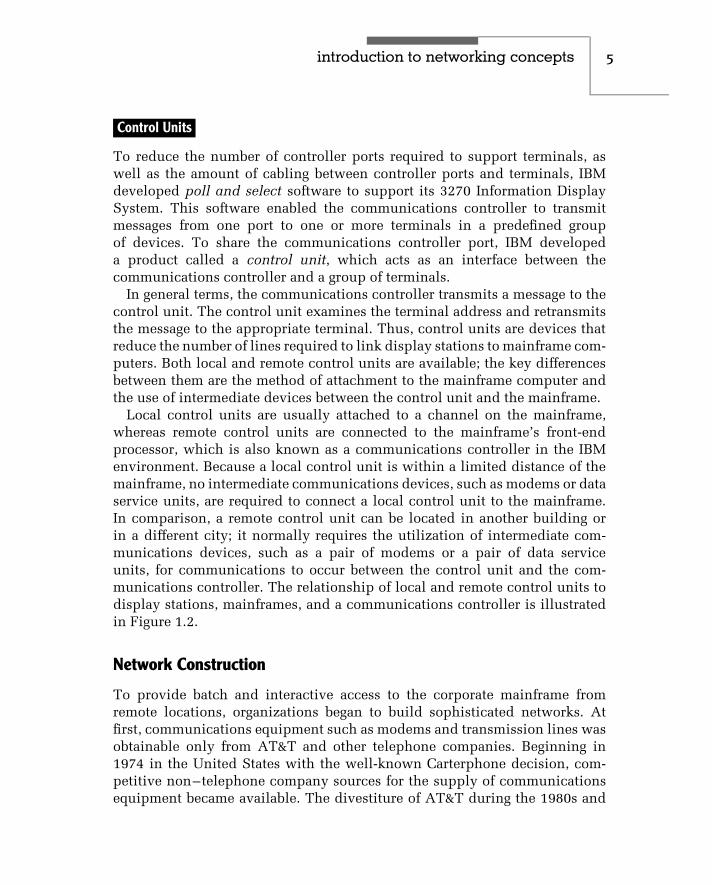
To reduce the number of controller ports required to support terminals, aswell as the amount of cabling between controller ports and terminals, IBMdeveloped poll and select software to support its 3270 Information DisplaySystem. This software enabled the communications controller to transmitmessages from one port to one or more terminals in a predefined groupof devices. To share the communications controller port, IBM developeda product called a control unit, which acts as an interface between thecommunications controller and a group of terminals.
In general terms, the communications controller transmits a message to thecontrol unit. The control unit examines the terminal address and retransmitsthe message to the appropriate terminal. Thus, control units are devices thatreduce the number of lines required to link display stations to mainframe com-puters. Both local and remote control units are available; the key differencesbetween them are the method of attachment to the mainframe computer andthe use of intermediate devices between the control unit and the mainframe.
Local control units are usually attached to a channel on the mainframe,whereas remote control units are connected to the mainframe’s front-endprocessor, which is also known as a communications controller in the IBMenvironment. Because a local control unit is within a limited distance of themainframe, no intermediate communications devices, such as modems or dataservice units, are required to connect a local control unit to the mainframe.In comparison, a remote control unit can be located in another building orin a different city; it normally requires the utilization of intermediate com-munications devices, such as a pair of modems or a pair of data serviceunits, for communications to occur between the control unit and the com-munications controller. The relationship of local and remote control units todisplay stations, mainframes, and a communications controller is illustratedin Figure 1.2.
Network Construction
To provide batch and interactive access to the corporate mainframe fromremote locations, organizations began to build sophisticated networks. Atfirst, communications equipment such as modems and transmission lines wasobtainable only from AT&T and other telephone companies. Beginning in1974 in the United States with the well-known Carterphone decision, com-petitive non–telephone company sources for the supply of communicationsequipment became available. The divestiture of AT&T during the 1980s and

6 c h a p t e r o n e
••
•
•
•Communications
controller
Mainframe
Localcontrol
unit
Terminal
Terminal
Modem* Modem*Remotecontrol
unit
Terminal
Terminal
*Note: Modems replaced by data service units when a digital transmission facility used.
Figure 1.2 Relationship of 3270 information display products.
the emergence of many local and long-distance communications carrierspaved the way for networking personnel to be able to select from amongseveral or even hundreds of vendors for transmission lines and communica-tions equipment.
As organizations began to link additional remote locations to their main-frames, the cost of providing communications began to escalate rapidly.This, in turn, provided the rationale for the development of a series of line-sharing products referred to as multiplexers and concentrators. Althoughmost organizations operated separate data and voice networks, in the mid-1980s communications carriers began to make available for commercial usehigh-capacity circuits known as T1 in North America and E1 in Europe.Through the development of T1 and E1 multiplexers, voice, data, and videotransmission can share the use of common high-speed circuits. Because theinterconnection of corporate offices with communications equipment andfacilities normally covers a wide geographical area outside the boundaryof one metropolitan area, the resulting network is known as a wide areanetwork (WAN).
Figure 1.3 shows an example of a wide area network spanning the continen-tal United States. In this example, regional offices in San Francisco and NewYork are connected with the corporate headquarters, located in Atlanta, via T1multiplexers and T1 transmission lines operating at 1.544 Mbps. Assumingthat each T1 multiplexer is capable of supporting the direct attachment ofa private branch exchange (PBX), both voice and data are carried by the T1circuits between the two regional offices and corporate headquarters. Thethree T1 circuits can be considered the primary data highway, or backbone,of the corporate network.

introduction to networking concepts 7
Macon, GA
Legend:
= Data Terminal
= Private Branch Exchange= Statistical Time Division Multiplexer
Atlanta, GA
STDM
PBX
56 Kbps digital circuitT
T1MUX
T
T
Sacramento, CA
San Francisco, CA
STDM
PBX
19.2 Kbps
Analog circuit
T
T1MUXT
T
T
T
T
Computer
ComputerT
T
New Haven, CT
New York, NY
STDM
T1MUX
PBX
19.2 Kbps
Analog circuit
PBXSTDM
1.544 MbpsT1
digitalcircuits
Figure 1.3 Wide area network example. A WAN uses telecommunicationslines obtained from one or more communications carriers to connect geo-graphically dispersed locations.
In addition to the three major corporate sites that require the ability to routevoice calls and data between locations, let us assume that the corporationalso has three smaller area offices located in Sacramento, California; Macon,Georgia; and New Haven, Connecticut. If these locations only require dataterminals to access the corporate network for routing to the computers located

8 c h a p t e r o n e
in San Francisco and New York, one possible mechanism to provide networksupport is obtained through the use of tail circuits. These tail circuits couldbe used to connect a statistical time division multiplexer (STDM) in each areaoffice, each serving a group of data terminals to the nearest T1 multiplexer,using either analog or digital circuits. The T1 multiplexer would then beconfigured to route data terminal traffic over the corporate backbone portionof the network to its destination.
Network Characteristics
There are certain characteristics we can associate with wide area networks.First, the WAN is typically designed to connect two or more geographical areas.This connection is accomplished by the lease of transmission facilities fromone or more communications vendors. Secondly, most WAN transmissionoccurs at or under a data rate of 1.544 Mbps or 2.048 Mbps, which are theoperating rates of T1 and E1 transmission facilities.
A third characteristic of WANs concerns the regulation of the transmissionfacilities used for their construction. Most, if not all, transmission facilitiesmarketed by communications carriers are subject to a degree of regulation atthe federal, state, and possibly local government levels. Even though we nowlive in an era of deregulation, carriers must seek approval for many offeringsbefore making new facilities available for use. In addition, although manyof the regulatory controls governing the pricing of services were removed,the communications market is still not a truly free market. Thus, regulatoryagencies at the federal, state, and local levels still maintain a degree ofcontrol over both the offering and pricing of new services and the pricing ofexisting services.
1.2 Local Area Networks
The origin of local area networks can be traced, in part, to IBM terminal equip-ment introduced in 1974. At that time, IBM introduced a series of terminaldevices designed for use in transaction-processing applications for bankingand retailing. What was unique about those terminals was their method of con-nection: a common cable that formed a loop provided a communications pathwithin a localized geographical area. Unfortunately, limitations in the datatransfer rate, incompatibility between individual IBM loop systems, and otherproblems precluded the widespread adoption of this method of networking.The economics of media sharing and the ability to provide common access

introduction to networking concepts 9
to a centralized resource were, however, key advantages, and they resultedin IBM and other vendors investigating the use of different techniques toprovide a localized communications capability between different devices. In1977, Datapoint Corporation began selling its Attached Resource ComputerNetwork (ARCNet), considered by most people to be the first commercial localarea networking product. Since then, hundreds of companies have developedlocal area networking products, and the installed base of terminal devicesconnected to such networks has increased exponentially. They now numberin the hundreds of millions.
Comparison to WANs
Local area networks can be distinguished from wide area networks by geo-graphic area of coverage, data transmission and error rates, ownership,government regulation, and data routing — and, in many instances, by thetype of information transmitted over the network.
Geographic Area
The name of each network provides a general indication of the scope ofthe geographic area in which it can support the interconnection of devices.As its name implies, a LAN is a communications network that covers arelatively small local area. This area can range in scope from a departmentlocated on a portion of a floor in an office building, to the corporate stafflocated on several floors in the building, to several buildings on the campusof a university.
Regardless of the LAN’s area of coverage, its geographic boundary will berestricted by the physical transmission limitations of the local area network.These limitations include the cable distance between devices connected to theLAN and the total length of the LAN cable. In comparison, a wide area networkcan provide communications support to an area ranging in size from a townor city to a state, country, or even a good portion of the entire world. Here,the major factor governing transmission is the availability of communicationsfacilities at different geographic areas that can be interconnected to route datafrom one location to another.
To better grasp the differences between LANs and WANs, today we can viewthe LAN as being analogous to our local telephone company, while the WANcan be compared with the long-distance communications carrier. However,this may not be true in the future when local telephone companies obtainpermission to offer long-distance service and long-distance communications

10 c h a p t e r o n e
carriers obtain regulatory approval to offer local telephone service. However,for the present we will presume that telephone support in different cities isprovided by the local telephone company in each city. Thus, for calls betweencities, the local telephone companies must connect to the long-distance carrier.Similarly, we can have separate LANs in different cities or within differentbuildings in the same city; however, to interconnect those LANs we wouldnormally require a wide area network.
Until the turn of the millennium these differences between LANs andWANs with the respect to geographic area of coverage were distinct andeasy to recognize. However, within the past two years a new role has beenproposed for Gigabit Ethernet that could enable this technology to functionas a miniature WAN. As we will note later in this book, the ability totransmit Gigabit Ethernet over optical fiber makes it possible to transmit thistechnology over extended distances. In fact, by the time you read this bookGigabit Ethernet may provide a low-cost alternative to synchronous opticalnetworking (SONET) transmission.
Data Transmission and Error Rates
Two additional areas that differentiate LANs from WANs and explain thephysical limitation of the LAN geographic area of coverage are the datatransmission rate and error rate for each type of network. Older LANs, suchas the original version of Ethernet and Token-Ring, normally operate at alow megabit-per-second rate, typically ranging from 4 Mbps to 16 Mbps. Moremodern high-speed Ethernet networks, such as Fast Ethernet that operatesat 100 Mbps, Gigabit Ethernet and 10 Gigabit Ethernet provide transmissionrates of 1 Gbps and 10 Gbps, respectively. In comparison, the communicationsfacilities used to construct a major portion of most WANs provide a datatransmission rate at or under the T1 and E1 data rates of 1.544 Mbps and2.048 Mbps.
Although some readers may have encountered references to WAN trans-mission rates of 10 and 40 Gbps in various trade literature, the use of opticalcarriers (OCs) at those data rates is primarily by communications carrierswhose transmission facilities are shared by tens of thousands to millions ofusers. Thus, in considering the data transmission rate with respect to LANsand WANs on a non-communications carrier basis, we can say that LANsprovide a transmission capacity up to 10 Gbps while WANs are limited to alow Mbps data rate.
Because LAN cabling is primarily within a building or over a small geograph-ical area, it is relatively safe from natural phenomena, such as thunderstormsand lightning. This safety enables transmission at a relatively high data rate,

introduction to networking concepts 11
resulting in a relatively low error rate. In comparison, because wide areanetworks are based on the use of communications facilities that are muchfarther apart and always exposed to the elements, they have a much higherprobability of being disturbed by changes in the weather, electronic emis-sions generated by equipment, or such unforeseen problems as constructionworkers accidentally causing harm to a communications cable. Because ofthese factors, the error rate on WANs is considerably higher than the rateexperienced on LANs. On most WANs you can expect to experience an errorrate between 1 in a million and 1 in 10 million (1 × 10⁶ to 1 × 10⁷) bits. Incomparison, the error rate on a typical LAN may exceed that range by one ormore orders of magnitude, resulting in an error rate from 1 in 10 million to 1in 100 million bits.
Ownership
The construction of a wide area network requires the leasing of transmis-sion facilities from one or more communications carriers. Although yourorganization can elect to purchase or lease communications equipment, thetransmission facilities used to connect diverse geographical locations areowned by the communications carrier. In comparison, an organization thatinstalls a local area network normally owns all of the components used toform the network, including the cabling used to form the transmission pathbetween devices.
Regulation
Because wide area networks require transmission facilities that may crosslocal, state, and national boundaries, they may be subject to a number ofgovernmental regulations at the local, state, and national levels. Most of thoseregulations govern the services that communications carriers can provide cus-tomers and the rates (tariff ) they can charge for those services. In comparison,regulations affecting local area networks are primarily in the areas of build-ing codes. Such codes regulate the type of wiring that can be installed in abuilding and whether the wiring must run in a conduit.
Data Routing and Topology
In a local area network data is routed along a path that defines the network.That path is normally a bus, ring, tree, or star structure, and data alwaysflows on that structure. The topology of a wide area network can be muchmore complex. In fact, many wide area networks resemble a mesh structure,

12 c h a p t e r o n e
including equipment to reroute data in the event of communications circuitfailure or excessive traffic between two locations. Thus, the data flow on awide area network can change, while the data flow on a local area networkprimarily follows a single basic route.
Type of Information Carried
The last major difference between local and wide area networks is the typeof information carried by each network. Many wide area networks supportthe simultaneous transmission of voice, data, and video information. Incomparison, most local area networks are currently limited to carrying data.In addition, although all wide area networks can be expanded to transportvoice, data, and video, many local area networks are restricted by design tothe transportation of data. An exception to the preceding is asynchronoustransfer mode (ATM), which can provide both a local and wide area networktransmission capability. Asynchronous transfer mode was designed to supportvoice, data, and video from end-to-end, enabling different types of data to betransported from one LAN to another via an ATM WAN. Unfortunately, thecost of ATM network adapters considerably exceeded the cost of other typesof LAN equipment used to include different types of Ethernet adapters. As thebase of Ethernet expanded, the cost associated with establishing an Ethernetinfrastructure decreased, widening the price gap between ATM and Ethernet,making it difficult for asynchronous transfer mode to establish a viable marketfor local area networking. Today the vast majority of ATM equipment is usedby communications carriers in the wide area network. Table 1.1 summarizesthe similarities and differences between local and wide area networks.
Utilization Benefits
In its simplest form, a local area network is a cable that provides an electronichighway for the transportation of information to and from different devicesconnected to the network. Because a LAN provides the capability to routedata between devices connected to a common network within a relativelylimited distance, numerous benefits can accrue to users of the network. Thesecan include the ability to share the use of peripheral devices, thus obtainingcommon access to data files and programs, the ability to communicate withother people on the LAN by electronic mail, and the ability to access thelarger processing capability of mainframes through common gateways thatlink a local area network to larger computer systems. Here, the gateway canbe directly cabled to the mainframe if it resides at the same location, or it maybe connected remotely via a corporate wide area network.

introduction to networking concepts 13
TABLE 1.1 Comparing LANs and WANs
Characteristic Local Area Network Wide Area Network
Geographic area ofcoverage
Localized to a building,group of buildings, orcampus
Can span an area ranging in sizefrom a city to the globe
Data transmissionrate
Typically 4 Mbps to16 Mbps, withhigh-speed Ethernet andfiber optic-basednetworks operating at100 Mbps and 1 and10 Gbps
Normally operate at or below T1and E1 transmission rates of1.544 Mbps and 2.048 Mbps
Error rate 1 in 107 to 1 in 108 1 in 106 to 1 in 107
Ownership Usually with theimplementor
Communications carrier retainsownership of line facilities
Data routing Normally follows fixedroute
Switching capability of networkallows dynamic alteration ofdata flow
Topology Usually limited to bus,ring, tree, or star
Virtually unlimited designcapability
Type of informationcarried
Primarily data Voice, data, and videocommonly integrated
Peripheral sharing allows network users to access color laser printers, CD-ROM jukebox systems, and other devices that may be needed only a smallportion of the time a workstation is in operation. Thus, users of a LAN canobtain access to resources that would probably be too expensive to justify foreach individual workstation user.
The ability to access data files and programs from multiple workstationscan substantially reduce the cost of software. In addition, shared access todatabase information allows network users to obtain access to updated fileson a real-time basis.
One popular type of application program used on LANs enables users totransfer messages electronically. Commonly referred to as electronic mail ore-mail, this type of application program can be used to supplement and, inmany cases, eliminate the need for paper memoranda.
For organizations with a mainframe, a local area network gateway canprovide a common method of access. Without the use of a LAN gateway, each

14 c h a p t e r o n e
personal computer requiring access to a mainframe would require a separatemethod of access. This might increase both the complexity and the cost ofproviding access.
Perhaps the most popular evolving use of LANs is to provide a group ofcomputer users with economical access to the Internet. Instead of havinga large number of employees obtain individual modem dial-up or ISDNdial access accounts with an Internet service provider (ISP), it is often moreeconomical to connect an organizational LAN to the Internet via a singleconnection to an ISP. In addition, the connection to the Internet will usuallyprovide a higher transmission capability than obtainable on an individualuser basis. Later in this book we will turn our attention to methods that canbe used to connect organizational LANs to the Internet, as well as the use ofdifferent products to protect organizational computer facilities from Internetusers that have no business accessing those facilities.
Technological Characteristics
Although a local area network is a limited distance transmission system,the variety of options available for constructing such networks is anythingbut limited. Many of the options available for the construction of localarea networks are based on the technological characteristics that governtheir operation. These characteristics include different topologies, signal-ing methods, transmission media, access methods used to transmit dataon the network, and the hardware and software required to make the net-work operate.
Topology
The topology of a local area network is the structure or geometric layout ofthe cable used to connect stations on the network. Unlike conventional datacommunications networks, which can be configured in a variety of ways withthe addition of hardware and software, most local area networks are designedto operate based on the interconnection of stations that follow a specifictopology. The most common topologies used in LANs include the loop, bus,ring, star, and tree, as illustrated in Figure 1.4.
Loop As previously mentioned in this chapter, IBM introduced a series oftransaction-processing terminals in 1974 that communicated through the useof a common controller on a cable formed into a loop. This type of topologyis illustrated at the top of Figure 1.4.

introduction to networking concepts 15
Loop
Bus
Ring
Star
Tree
Controller
Figure 1.4 Local area network topology. The five most common geometriclayouts of LAN cabling form a loop, bus, ring, star, or tree structure.
Because the controller employed a poll-and-select access method, terminaldevices connected to the loop required a minimum of intelligence. Althoughthis reduced the cost of terminals connected to the loop, the controller lackedthe intelligence to distribute the data flow evenly among terminals. A lengthyexchange between two terminal devices or between the controller and aterminal would thus tend to bog down this type of network structure. Asecond problem associated with this network structure was the centralized

16 c h a p t e r o n e
placement of network control in the controller. If the controller failed, theentire network would become inoperative. Due to these problems, the useof loop systems is restricted to several niche areas, and they are essentiallyconsidered a derivative of a local area network.
Bus In a bus topology structure, a cable is usually laid out as one longbranch, onto which other branches are used to connect each station onthe network to the main data highway. Although this type of structurepermits any station on the network to talk to any other station, rules arerequired for recovering from such situations as when two stations attemptto communicate at the same time. Later in this chapter, we will examinethe relationships among the network topology, the method employed toaccess the network, and the transmission medium employed in buildingthe network.
Ring In a ring topology, a single cable that forms the main data highway isshaped into a ring. As with the bus topology, branches are used to connectstations to one another via the ring. A ring topology can thus be consideredto be a looped bus. Typically, the access method employed in a ring topologyrequires data to circulate around the ring, with a special set of rules governingwhen each station connected to the network can transmit data.
Star The fourth major local area network topology is the star structure,illustrated in the lower portion of Figure 1.4. In a star network, each stationon the network is connected to a network controller. Then, access fromany one station on the network to any other station can be accomplishedthrough the network controller. Here, the network controller functions likea telephone switchboard, because access from one station to another stationon the network can occur only through the central device. In fact, you canconsider a telephone switchboard or PBX as representing a star-structuredLAN whose trunks provide connections to the wide area network telephoneinfrastructure.
Tree A tree network structure represents a complex bus. In this topology,the common point of communications at the top of the structure is knownas the headend. From the headend, feeder cables radiate outward to nodes,which in turn provide workstations with access to the network. There mayalso be a feeder cable route to additional nodes, from which workstations gainaccess to the network. One common example of a tree structure topology isthe cable TV network many readers use on a daily basis. With the upgrade
introduction to networking concepts 17
of many cable TV systems to two-way amplifiers and the support of digitaltransmission, the local cable TV infrastructure can be considered to representan evolving type of tree-structured local area network.
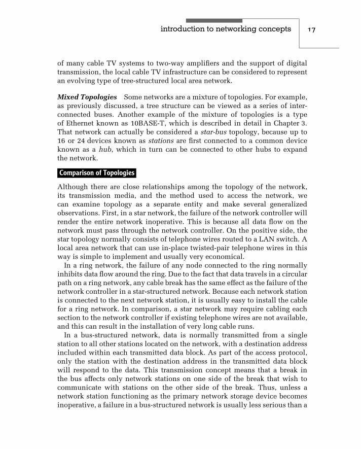
Mixed Topologies Some networks are a mixture of topologies. For example,as previously discussed, a tree structure can be viewed as a series of inter-connected buses. Another example of the mixture of topologies is a typeof Ethernet known as 10BASE-T, which is described in detail in Chapter 3.That network can actually be considered a star-bus topology, because up to16 or 24 devices known as stations are first connected to a common deviceknown as a hub, which in turn can be connected to other hubs to expandthe network.
Comparison of Topologies
Although there are close relationships among the topology of the network,its transmission media, and the method used to access the network, wecan examine topology as a separate entity and make several generalizedobservations. First, in a star network, the failure of the network controller willrender the entire network inoperative. This is because all data flow on thenetwork must pass through the network controller. On the positive side, thestar topology normally consists of telephone wires routed to a LAN switch. Alocal area network that can use in-place twisted-pair telephone wires in thisway is simple to implement and usually very economical.
In a ring network, the failure of any node connected to the ring normallyinhibits data flow around the ring. Due to the fact that data travels in a circularpath on a ring network, any cable break has the same effect as the failure of thenetwork controller in a star-structured network. Because each network stationis connected to the next network station, it is usually easy to install the cablefor a ring network. In comparison, a star network may require cabling eachsection to the network controller if existing telephone wires are not available,and this can result in the installation of very long cable runs.
In a bus-structured network, data is normally transmitted from a singlestation to all other stations located on the network, with a destination addressincluded within each transmitted data block. As part of the access protocol,only the station with the destination address in the transmitted data blockwill respond to the data. This transmission concept means that a break inthe bus affects only network stations on one side of the break that wish tocommunicate with stations on the other side of the break. Thus, unless anetwork station functioning as the primary network storage device becomesinoperative, a failure in a bus-structured network is usually less serious than a

18 c h a p t e r o n e
failure in a ring network. However, some local area networks, such as Token-Ring and FDDI, were designed to overcome the effect of certain types of cablefailures. Token-Ring networks include a backup path which, when manuallyplaced into operation, may be able to overcome the effect of a cable failurebetween hubs (referred to as multistation access units or MAUs). In an FDDInetwork, a second ring can be activated automatically as part of a self-healingprocess to overcome the effect of a cable break.
A tree-structured network is similar to a star-structured network in thatall signals flow through a common point. In the tree-structured network,the common signal point is the headend. Failure of the headend rendersthe network inoperative. This network structure requires the transmissionof information over relatively long distances. For example, communicationsbetween two stations located at opposite ends of the network would requirea signal to propagate twice the length of the longest network segment. Dueto the propagation delay associated with the transmission of any signal, theuse of a tree structure may result in a response time delay for transmissionsbetween the nodes that are most distant from the headend.
Although the first type of Ethernet network was based on a bus-structuredtopology, other types of Ethernet networks incorporate the use of differenttopologies. Today you can select bus-based, star-bus, or tree-structured Eth-ernet networks. Thus, you can select a particular type of Ethernet network tomeet a particular topology requirement.
Signaling Methods
The signaling method used by a local area network refers to both the waydata is encoded for transmission and the frequency spectrum of the media.To a large degree, the signaling method is related to the use of the frequencyspectrum of the media.
Broadband versus Baseband
Two signaling methods used by LANs are broadband and baseband. In broad-band signaling, the bandwidth of the transmission medium is subdivided byfrequency to form two or more subchannels, with each subchannel permittingdata transfer to occur independently of data transfer on another subchannel.In baseband signaling, only one signal is transmitted on the medium at anypoint in time.
Broadband is more complex than baseband, because it requires informationto be transmitted via the modulation of a carrier signal, thus requiring the useof special types of modems, as discussed later in this chapter.
introduction to networking concepts 19
Baseband
Broadband
Single channel
Frequency
Multiple channels
Frequency
A B N
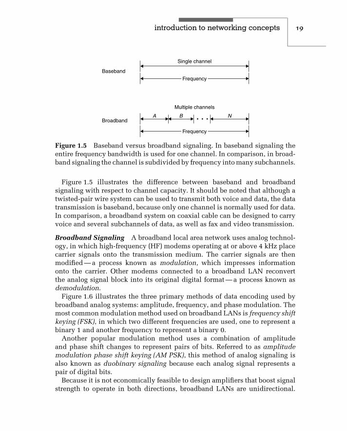
Figure 1.5 Baseband versus broadband signaling. In baseband signaling theentire frequency bandwidth is used for one channel. In comparison, in broad-band signaling the channel is subdivided by frequency into many subchannels.
Figure 1.5 illustrates the difference between baseband and broadbandsignaling with respect to channel capacity. It should be noted that although atwisted-pair wire system can be used to transmit both voice and data, the datatransmission is baseband, because only one channel is normally used for data.In comparison, a broadband system on coaxial cable can be designed to carryvoice and several subchannels of data, as well as fax and video transmission.
Broadband Signaling A broadband local area network uses analog technol-ogy, in which high-frequency (HF) modems operating at or above 4 kHz placecarrier signals onto the transmission medium. The carrier signals are thenmodified — a process known as modulation, which impresses informationonto the carrier. Other modems connected to a broadband LAN reconvertthe analog signal block into its original digital format — a process known asdemodulation.
Figure 1.6 illustrates the three primary methods of data encoding used bybroadband analog systems: amplitude, frequency, and phase modulation. Themost common modulation method used on broadband LANs is frequency shiftkeying (FSK), in which two different frequencies are used, one to represent abinary 1 and another frequency to represent a binary 0.
Another popular modulation method uses a combination of amplitudeand phase shift changes to represent pairs of bits. Referred to as amplitudemodulation phase shift keying (AM PSK), this method of analog signaling isalso known as duobinary signaling because each analog signal represents apair of digital bits.
Because it is not economically feasible to design amplifiers that boost signalstrength to operate in both directions, broadband LANs are unidirectional.

20 c h a p t e r o n e
Phasemodulation
Frequencymodulation
Amplitudemodulation
Digital signal 1 0 1 1 0
Figure 1.6 Modulation methods. Baseband signaling uses amplitude, fre-quency, or phase modulation, or a combination of modulation techniques torepresent digital information.
To provide a bidirectional information transfer capability, a broadband LANuses one channel for inbound traffic and another channel for outbound traffic.These channels can be defined by differing frequencies or obtained by the useof a dual cable.
Baseband Signaling In comparison to broadband local area networks,which use analog signaling, baseband LANs use digital signaling to conveyinformation.
To understand the digital signaling methods used by most baseband LANs,let us first review the method of digital signaling used by computers andterminal devices. In that signaling method, a positive voltage is used torepresent a binary 1, while the absence of voltage (0 volts) is used to representa binary 0. If two successive 1 bits or 0 bits occur, two successive bit positionsthen have a similar positive voltage level or a similar zero voltage level.

introduction to networking concepts 21
Because the signal goes from 0 to some positive voltage and does not returnto 0 between successive binary 1s, it is referred to as a unipolar nonreturnto zero signal (NRZ). This signaling technique is illustrated at the top ofFigure 1.7.
Although unipolar NRZ signaling is easy to implement, its use for trans-mission has several disadvantages. One of the major disadvantages associatedwith this signaling method involves determining where one bit ends andanother begins. For example, if you examine the top portion of Figure 1.7 youwill note that the bit sequences ‘‘00’’ and ‘‘111’’ remain at distinct voltagelevels. Thus, the ability to recognize that a sequence of two or more pulses ofthe same value occurred requires synchronization between a transmitter andreceiver by the use of clocking circuitry, which can be relatively expensive.
To overcome the need for clocking, baseband LANs use Manchester orDifferential Manchester encoding. In Manchester encoding, a timing transitionalways occurs in the middle of each bit, while an equal amount of positiveand negative voltage is used to represent each bit. This coding techniqueprovides a good timing signal for clock recovery from received data, dueto its timing transitions. In addition, because the Manchester code alwaysmaintains an equal amount of positive and negative voltage, it prevents directcurrent (DC) voltage buildup, enabling repeaters to be spaced farther apartfrom one another.
1 1110100
Unipolar nonreturn to zero
Manchester coding
Linesignal
+V
−V
Figure 1.7 Unipolar nonreturn to zero signaling and Manchester coding. InManchester coding, a timing transition occurs in the middle of each bit andthe line code maintains an equal amount of positive and negative voltage.

22 c h a p t e r o n e
The lower portion of Figure 1.7 illustrates an example of Manchester coding.Note that a low to high voltage transition represents a binary 1, while a highto low voltage transition represents a binary 0. A second type of Manchestercoding is referred to as Differential Manchester encoding. Under DifferentialManchester encoding, the voltage transition is used only to provide clocking.The encoding of a binary 0 or 1 is represented by the presence or absenceof a transition at the beginning of each bit period. Refer to Chapter 4 forspecific information concerning Manchester encoding on different types ofEthernet networks.
Along with providing users with a choice of topologies, Ethernet alsoprovides a choice of signaling methods. Although most types of Ethernetnetworks use baseband signaling, a broadband Ethernet is also available. Infact, you can connect baseband- and broadband-based Ethernet networks tosatisfy different organizational requirements. Refer to Chapter 3 for specificinformation concerning the signaling methods used by different Ethernetnetworks and the hardware components used to construct and interconnectsuch networks.
Transmission Medium
The transmission medium used in a local area network can range in scope fromtwisted-pair wire, such as is used in conventional telephone lines, to coaxialcable, fiber-optic cable, and electromagnetic waves such as those used by FMradio and infrared. Each transmission medium has a number of advantagesand disadvantages. The primary differences between media are their cost andease of installation; the bandwidth of the cable, which may or may not permitseveral transmission sessions to occur simultaneously; the maximum speedof communications permitted; and the geographic scope of the network thatthe medium supports.
Twisted-Pair Wire
In addition to being the most inexpensive medium available for LAN installa-tions, twisted-pair wire is very easy to install. Since this wiring uses the sameRJ11 and RJ45 modular connectors as a telephone system, once a wire is cutand a connector fastened, the attachment of the connector to network devicesis extremely simple. Normally, a screwdriver and perhaps a pocket knife arethe only tools required for the installation of twisted-pair wire. Anyone whohas hooked up a pair of speakers to a stereo set has the ability to install thistransmission medium.

introduction to networking concepts 23
Although inexpensive and easy to install, unshielded twisted-pair (UTP)wire is very susceptible to noise generated by fluorescent light ballasts andelectrical machinery. In addition, a length of twisted-pair wire acts as anantenna; however, the twists serve as a mechanism to partially counteractthis antenna effect. Unfortunately, due to the law of physics, the longer thewire length, the greater the noise it gathers. At a certain length, the receivednoise will obliterate the signal, which attenuates or decreases in strength asit propagates along the length of the wire. This noise can affect the error rateof data transmitted on the network, although lead-shielded twisted-pair (STP)cable can be employed to provide the cable with a high degree of immunityto the line noise and enable extended transmission distances. In Chapter 3we will examine a building cabling standard and the various categories oftwisted-pair that can support different transmission rates which, in turn,enable different types of Ethernet networks to be supported.
Because the bandwidth of twisted-pair cable is considerably less thancoaxial or fiber-optic cable, normally only one signal is transmitted on thiscable at a time. As previously explained, this signaling technique is knownas baseband signaling and should be compared with the broadband signalingcapability of coaxial and fiber-optic cable.
Although a twisted-pair wire system can be used to transmit both voice anddata, the data transmission is baseband because only one channel is normallyused for data. In comparison, a broadband system on coaxial or fiber-opticcable can be designed to carry voice and several subchannels of data, as wellas fax and video transmission. Other constraints of unshielded twisted-pairwire are the rate at which data can flow on the network and the distance it canflow. Although data rates up to 1 gigabit per second (Gbps) can be achieved,normally local area networks employing UTP wiring operate at a lower datarate. In addition, UTP systems normally cover a limited distance, measured interms of several hundred to a few thousand feet, while coaxial and fiber-opticcable–based systems may be limited in terms of miles. Extending transmissiondistances over twisted-pair wire requires the periodic insertion of repeatersinto the cable. A repeater receives a digital signal and then regenerates it;hence, it is also known as a data regenerator.
Coaxial Cable
At the center of a coaxial cable is a copper wire, which is covered byan insulator known as a dielectric. An overlapping woven copper meshsurrounds the dielectric, and the mesh, in turn, is covered by a protectivejacket consisting of polyethylene or aluminum. Figure 1.8 illustrates the

24 c h a p t e r o n e
Protective polyethylene jacket
Polyethylenedielectric
Overlapped-seamcopper outer
conductor Copper innerconductor
Steel strengthmember
Figure 1.8 Coaxial cable.
composition of a typical coaxial cable; however, it should be noted thatover 100 types of coaxial cable are currently marketed. The key differencesbetween such cables involve the number of conductors contained in thecable, the dielectric employed, and the type of protective jacket and materialused to provide strength to the cable so it can be pulled through conduitswithout breaking.
Two basic types of coaxial cable are used in local area networks. The typeof cable used is based on the transmission technique employed: basebandor broadband signaling. Both cable types are much more expensive thantwisted-pair wire; however, the greater frequency bandwidth of coaxial cablepermits higher data rates for longer distances than you can obtain overtwisted-pair wire.
Normally, 50-ohm coaxial cable is used in baseband networks, while 75-ohm cable is used in broadband networks. The latter coaxial is identical tothat used in cable television (CATV) applications, including the coaxial cableused in a home. Data rates on baseband networks using coaxial cable rangefrom 50 to 100 Mbps. With broadband transmissions, data rates up to andincluding 400 Mbps are obtainable.
A coaxial cable with a polyethylene jacket is normally used for basebandsignaling. Data is transmitted from stations on the network to the base-band cable in a digital format, and the connection from each station to thecable is accomplished by the use of a simple coaxial T-connector. Becausedata on a baseband network travels in a digital form, those signals can be

introduction to networking concepts 25
easily regenerated by the use of a device known as a line driver or dataregenerator. The line driver or data regenerator is a low-cost device that isconstructed to look for a pulse rise, and upon detecting the occurrence ofthe rise, it will disregard the entire pulse and regenerate an entirely newpulse. Thus, you can install low-cost line drivers into a baseband coax-ial network to extend the distance over which transmission can occur onthe cable. Typically, a coaxial cable baseband system can cover an areaof several miles, and may contain hundreds to thousands of stations onthe network.
Obtaining independent subchannels defined by separate frequencies oncoaxial cable broadband transmission requires the translation of the digi-tal signals from workstations into appropriate frequencies. This translationprocess is accomplished by the use of radio-frequency (RF) modems, whichmodulate the digital data into analog signals and then convert or demodulatereceived analog signals into digital signals. Because signals are transmitted atone frequency and received at a different frequency, a headend or frequencytranslator is also required for broadband transmission on coaxial cable. Thisdevice is also known as a remodulator, as it simply converts the signals fromone subchannel to another subchannel.
Fiber-Optic Cable
Fiber-optic cable is a transmission medium for light energy, and as such,provides a very high bandwidth, permitting data rates ranging up to billionsof bits per second. The fiber-optic cable has a thin core of glass or plastic,which is surrounded by a protective shield. Several of these shielded fibersare bundled in a jacket, with a central member of aluminum or steel employedfor tensile strength.
Digital data represented by electrical energy must be converted into lightenergy for transmission on a fiber-optic cable. This is normally accom-plished by a low-power laser, or through the use of a light-emitting diodeand appropriate circuitry. At the receiver, light energy must be recon-verted into electrical energy. Normally, a device known as a photo detector,as well as appropriate circuitry to regenerate the digital pulses and anamplifier, are used to convert the received light energy into its originaldigital format.
Figure 1.9 provides an illustration of the cross section of a single-strandfiber cable. The cladding that surrounds the core of the fiber can be consideredto represent a cylindrical mirror whose job is to ensure light stays in the coreas it flows along the fiber. The kevlar fibers add strength to the cable, while the

26 c h a p t e r o n e
Core
Outer jacket
Kelvar fibers
Buffercoating
Cladding
Figure 1.9 Horizontal cross section of a single-strand fiber cable.
outer jacket, which is commonly colored orange, represents a polymer-basedshield that protects the cable from the elements.
There are two key factors that govern the manner by which light flowsthrough a fiber-optic cable. Those factors are the diameter of the core and thelight source. The first type of fiber-optic cable developed had a relatively largediameter that ranged from 50 to 140 microns, where a micron is a millionthof a meter. The original light source used to transmit information was alight-emitting diode (LED). The coupling of an LED to a large-diameter opticalfiber results in photons flowing along multiple paths through the optical fiber,resulting in the transmission referred to as multimode, which is also the samename used to reference the type of optical fiber.
There are two types of multimode fiber, referred to as step-index and graded-index. A step-index fiber has a core with a uniform refractive index, resultingin the different components of a light signal in the form of modes or raysflowing in a non-uniform manner through the optical cable. The top portion ofFigure 1.10 illustrates the flow of light through a step-index, multimode fiber.
In a graded-index multimode fiber, the refractive index is varied from thecenter to the edge of the core to minimize modal dispersion. The middleportion of Figure 1.10 illustrates the flow of light through a graded-index,multimode fiber. This type of fiber minimizes model dispersion and supportshigher data rates than a step-index multimode optical fiber.
A third type of optical fiber has a relatively small core diameter, typicallybetween 7 and 12 microns (10−6 meters). This type of optical fiber permitsonly one path for the flow of light due to the small diameter of the core. As

introduction to networking concepts 27
LED
Graded–index, multimode
LED
Step–index, multimode
LASER
Single mode
Figure 1.10 Light flow in multimode and single-mode optical fiber.
a result of the lack of modal dispersion, single mode supports a much higherdata rate than multimode fiber. Because of the small diameter of single-modefiber, lasers are used as the light source instead of LEDs.
Both the core thickness and the cladding of an optical fiber are measuredin microns. The three major core thicknesses used in optical fiber are 50, 62and 100 microns. The associated claddings for those core diameters are 125,125 and 140 microns, respectively. Table 1.2 summarizes the relationshipsbetween core and cladding diameters for single-mode and multimode fiber.
In trade literature you will note what appears as a ratio in the form of x/ywhen the metrics associated with an optical fiber are referenced. In actuality,this is not a ratio but instead references the core and the cladding thicknessof an optical fiber in microns. Thus, 50/125 would, for example, reference anoptical fiber whose core diameter is 50 microns and whose cladding diameteris 125 microns.
In addition to their high bandwidth, fiber-optic cables offer users severaladditional advantages over conventional transmission media. Because datatravels in the form of light, it is immune to electrical interference and to thebuilding codes that often require expensive conduits for conventional cables.

28 c h a p t e r o n e
TABLE 1.2 Common Core and CladdingDiameters of Optical Fiber in Microns
ModeGlass CoreDiameter
GlassCladding
Single-mode 2–8 20
Multimode 50 125
62 125
100 140
Similarly, fiber-optic cable can be installed through areas where the flow ofelectricity could be dangerous.
Because most fibers provide only a single, unidirectional transmission path,a minimum of two cables is normally required to connect all transmitters toall receivers on a network built using fiber-optic cable. Due to the higher costof fiber-optic cable, the dual cable requirement of fiber cables can make themrelatively expensive in comparison with other types of cable. In addition,until recently it was very difficult to splice fiber-optic cable, and sophisticatedequipment and skilled installers were required to implement a fiber-optic-based network. Similarly, once this type of network was installed, untilrecently it was difficult to modify the network. Recent advances in fibertransmission through the use of wavelength division multiplexing enables twoor more transmission paths separated by the frequency of light to be carriedon a common optical cable. Although wavelength division multiplexing isbeing used in the long-distance fiber backbones of communications carriers toincrease the transmission capacity of their infrastructure, the cost of electro-optical transmitter receivers to support this technology usually precludes itsuse with local area networks.
Currently, the cost of the cable and the degree of difficulty of installationand modification make the utilization of fiber-optic-based local area networksimpractical for many commercial applications. Today, the primary use offiber-optic cable is to extend the distance between stations on a network orto connect two distant networks to one another. The device used to connecta length of fiber-optic cable into the LAN or between LANs is a fiber-opticrepeater. The repeater converts the electrical energy of signals flowing onthe LAN into light energy for transmission on the fiber-optic cable. At theend of the fiber-optic cable, a second repeater converts light energy back intoelectrical energy. A key exception to the preceding involves Gigabit Ethernet,

introduction to networking concepts 29
whose data rate normally requires the use of optical fiber as a transportmedium. Although Gigabit Ethernet can operate on copper conductors, itstransmission distance is limited in comparison to when optical fiber is used.With the declining cost of the fiber-optic cable and fiber-optic components,and the continued introduction of improvements that simplify the installationand modification of networks using this type of cable, the next few years maybring a profound movement toward the utilization of fiber optics throughoutlocal area networks.
Ethernet can be categorized as a network for everyone, because of itssupport of multiple topologies, signaling methods, and transmission media.In addition to twisted-pair and coaxial cable-based Ethernet networks, youcan also extend the transmission distance of such networks by the use offiber-optic cable. Thus, the old adage from a presidential campaign, ‘‘a choicenot an echo,’’ is highly relevant to Ethernet networks.
Access Method
If the topology of a local area network can be compared with a data highway,then the access method might be viewed as the set of rules that enable data fromone workstation to successfully reach its destination via the data highway.Without such rules, it is quite possible for two messages sent by two differentworkstations to collide, with the result that neither message reaches its destina-tion. The three access methods primarily employed in local area networks arecarrier-sense multiple access/collision detection (CSMA/CD), carrier-sensemultiple access/collision avoidance (CSMA/CA), and token passing. Eachof these access methods is uniquely structured to address the previouslymentioned collision and data-destination problems. A fourth access method,referred to as demand priority, is applicable to a high-speed Ethernet networkreferred to as 100VG-AnyLAN. Through the use of a demand-priority accessmethod you can support either existing Ethernet CSMA/CD or token passingnetworks at 100 Mbps.
Before discussing how access methods work, let us first examine the twobasic types of devices that can be attached to a local area network to gain anappreciation for the work that the access method must accomplish.
Listeners and Talkers
We can categorize each device by its operating mode as being a listener or atalker. Some devices, like printers, only receive data, and thus operate onlyas listeners. Other devices, such as personal computers, can either transmitor receive data and are capable of operating in both modes. In a baseband

30 c h a p t e r o n e
signaling environment where only one channel exists, or on an individualchannel on a broadband system, if several talkers wish to communicate at thesame time, a collision will occur. Therefore, a scheme must be employed todefine when each device can talk and, in the event of a collision, what mustbe done to keep it from happening again.
For data to reach its destination correctly, each listener must have a uniqueaddress, and its network equipment must be designed to respond to a messageon the net only when it recognizes its address. The primary goals in thedesign of an access method are to minimize the potential for data collision,to provide a mechanism for corrective action when data does collide, and toensure that an addressing scheme is employed to enable messages to reachtheir destinations.
Carrier-Sense Multiple Access with Collision Detection (CSMA/CD)
CSMA/CD can be categorized as a listen-then-send access method. CSMA/CDis one of the earliest developed access techniques and is the technique usedin Ethernet. Ethernet represents a local area network developed by XeroxCorporation; its technology is now licensed to many companies, and wasstandardized by the Institute of Electrical and Electronics Engineers (IEEE)under its 802.3 standard.
Under the CSMA/CD concept, when a station has data to send, it first listensto determine whether any other station on the network is talking. The fact thatthe channel is idle is determined in one of two ways, based on whether thenetwork is broadband or baseband.
In a broadband network, the fact that a channel is idle is determined bycarrier sensing, or noting the absence of a carrier tone on the cable.
Ethernet, like other baseband systems, uses one channel for data transmis-sion and does not employ a carrier. Instead, Ethernet encodes data using aManchester code, in which a timing transition always occurs in the middleof each bit, as previously illustrated in Figure 1.7. Although Ethernet doesnot transmit data via a carrier, the continuous transitions of the Manchestercode can be considered as equivalent to a carrier signal. Carrier sensingon a baseband network is thus performed by monitoring the line for activ-ity. Manchester coding is used by Ethernet at data rates up to 10 Mbps.At operating rates above 10 Mbps, different encoding techniques are used,which provide a higher level of efficiency than Manchester’s 50-percent levelof efficiency.
In a CSMA/CD network, if the channel is busy, the station will wait until itbecomes idle before transmitting data. Because it is possible for two stations tolisten at the same time and discover an idle channel, it is also possible that the
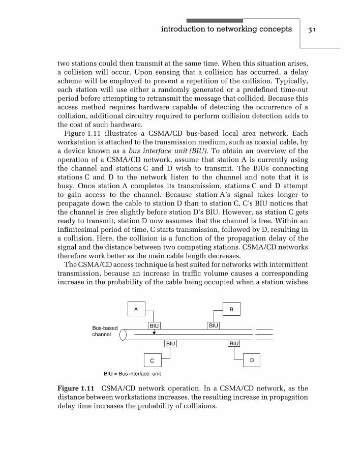
introduction to networking concepts 31
two stations could then transmit at the same time. When this situation arises,a collision will occur. Upon sensing that a collision has occurred, a delayscheme will be employed to prevent a repetition of the collision. Typically,each station will use either a randomly generated or a predefined time-outperiod before attempting to retransmit the message that collided. Because thisaccess method requires hardware capable of detecting the occurrence of acollision, additional circuitry required to perform collision detection adds tothe cost of such hardware.
Figure 1.11 illustrates a CSMA/CD bus-based local area network. Eachworkstation is attached to the transmission medium, such as coaxial cable, bya device known as a bus interface unit (BIU). To obtain an overview of theoperation of a CSMA/CD network, assume that station A is currently usingthe channel and stations C and D wish to transmit. The BIUs connectingstations C and D to the network listen to the channel and note that it isbusy. Once station A completes its transmission, stations C and D attemptto gain access to the channel. Because station A’s signal takes longer topropagate down the cable to station D than to station C, C’s BIU notices thatthe channel is free slightly before station D’s BIU. However, as station C getsready to transmit, station D now assumes that the channel is free. Within aninfinitesimal period of time, C starts transmission, followed by D, resulting ina collision. Here, the collision is a function of the propagation delay of thesignal and the distance between two competing stations. CSMA/CD networkstherefore work better as the main cable length decreases.
The CSMA/CD access technique is best suited for networks with intermittenttransmission, because an increase in traffic volume causes a correspondingincrease in the probability of the cable being occupied when a station wishes
BIU BIU
BIU BIU
A B
DC
BIU = Bus interface unit
Bus-basedchannel
Figure 1.11 CSMA/CD network operation. In a CSMA/CD network, as thedistance between workstations increases, the resulting increase in propagationdelay time increases the probability of collisions.

32 c h a p t e r o n e
to talk. In addition, as traffic volume builds under CSMA/CD, throughput maydecline, because there will be longer waits to gain access to the network, aswell as additional time-outs required to resolve collisions that occur. In spiteof the lower level of throughput, as we will note later in this book CSMA/CAis used as the access method supported by many types of wireless LANsincluding several types of wireless Ethernet LANs.
Carrier-Sense Multiple Access with Collision Avoidance (CSMA/CA)
CSMA/CA represents a modified version of the CSMA/CD access technique.Under the CSMA/CA access technique, each of the hardware devices attachedto the talkers on the network estimates when a collision is likely to occurand avoids transmission during those times. Because this technique elimi-nates the requirement for collision-detection hardware, the cost of hardwareto implement this access technique is usually less than CSMA/CD hard-ware. Unfortunately, time delays associated with collision avoidance usuallyresult in a lower level of throughput than that obtainable with CSMA/CD-based networks, and this limitation has made CSMA/CA-based networksless popular.
Token Passing
In a token-passing access method, each time the network is turned on, a tokenis generated. The token, consisting of a unique bit pattern, travels the lengthof the network, either around a ring or along the length of a bus. When astation on the network has data to transmit, it must first seize a free token.On a Token-Ring network, the token is then transformed to indicate that itis in use. Information is added to produce a frame, which represents databeing transmitted from one station to another. During the time the token is inuse, other stations on the network remain idle, eliminating the possibility ofcollisions. Once the transmission is completed, the token is converted backinto its original form by the station that transmitted the frame, and becomesavailable for use by the next station on the network.
Figure 1.12 illustrates the general operation of a token-passing Token-Ringnetwork using a ring topology. Because a station on the network can onlytransmit when it has a free token, token passing eliminates the requirementfor collision detection hardware. Due to the dependence of the network onthe token, the loss of a station can bring the entire network down. To avoidthis, the design characteristics of Token-Ring networks include circuitry thatautomatically removes a failed or failing station from the network, as well asother self-healing features. This additional capability is costly: a Token-Ring

introduction to networking concepts 33
B
D
CA
T
B
D
CA
F
B
D
A C
F
B
D
CA
T
Workstation with datato transmit looks forfree token
Workstation changestoken into a frame,adding data to theframe and itsdestination address
Destination stationcopies data addressedto it
Frame flows back tooriginator, which removesthe frame from thenetwork and generates anew token
Figure 1.12 Token-Ring operation.
adapter card is typically priced at two to three times the cost of an Ethernetadapter card.
Due to the variety of transmission media, network structures, and accessmethods, there is no one best network for all users. Table 1.3 provides ageneralized comparison of the advantages and disadvantages of the technicalcharacteristics of local area networks, using the transmission medium as aframe of reference.

34 c h a p t e r o n e
TABLE 1.3 Technical Characteristics of LANs
Transmission Medium
Characteristic Twisted-pairwire
Basebandcoaxial cable
Basebandcoaxial cable
Fiber-opticcable
Topology Bus, star, orring
Bus or ring Bus or ring Bus, star, or ring
Channels Singlechannel
Singlechannel
Multichannel Single,multichannel
Data rate Normally 4 to16 Mbps; upto 1000 Mbpsobtainable
Normally 2 to10 Mbps; upto 100 Mbpsobtainable
Up to 400 Mbps Up to 40 Gbps
Maximumnodes on net
Usually <255 Usually<1024
Severalthousand
Severalthousand
Geographicalcoverage
Thousands offeet
Miles Tens of miles Tens of miles
Majoradvantages
Low cost;may be ableto useexistingwiring
Low cost;simple toinstall
Supports voice,data, videoapplicationssimultaneously
Supports voice,data, videoapplicationssimultaneously
Majordisadvantages
Limitedbandwidth;requiresconduits; lowimmunity tonoise
Lowimmunity tonoise
High cost;difficult toinstall; requiresRF modems andheadend
Cable cost;difficult tosplice
1.3 Why Ethernet
After reviewing the basic characteristics of various local area networks, youwill note that they present a considerable range of technological characteris-tics. You can select a network based on its topology, access method, signalingmethod, and/or support of a particular type of transmission medium. Althoughthere is no one best network for all users, Ethernet represents a diverse mix-ture of technological characteristics. As such, it provides many more potentialnetworking solutions to user communications requirements than other typesof local area networks.

introduction to networking concepts 35
In addition to supporting a broad range of technological characteristics,Ethernet is a declining-cost network. Due to economies of manufacture, aswell as the recent support of twisted-pair wiring, Ethernet networks can beestablished for a fraction of the cost of other types of local area networks.In fact, by late 2002, adapter cards supporting 10 Mbps Ethernet that weredesigned for use in IBM PCs and compatible personal computers could beobtained for under $20, while 10/100 Mbps adapter cards could be obtainedfor under $50. In addition, several notebook and laptop computer vendors,as well as vendors of many business desktop systems, were incorporat-ing Ethernet chip sets into their computers, enabling computer users whowant to transfer files to other computers and printers connected to the net-work to simply plug their computer into a telephone jack upon returning tothe office.
Although the previously mentioned reasons are significant, the scalabil-ity of Ethernet and the product development effort of industry provide twoadditional reasons to use Ethernet. Concerning scalability, you can obtaininteroperable Ethernet equipment that enables you to operate a networkoriginally at 10 Mbps and have the option of using a variety of vendorproducts to upgrade your network to 100 Mbps or even 1 or 10 Gbps.Concerning product development, over the past decade a large number ofproducts reached the market that enable Ethernet users to boost the per-formance and management of their networks. Perhaps the most versatileproduct is actually a series of Ethernet switches that enable multiple cross-connections between workstations and servers to occur simultaneously, aswell as enable the transmission on multiple ports to be aggregated, a tech-nique referred to as a fat pipe. Over the past five years the capability of LANswitches has been significantly enhanced. Today many LAN switch manu-facturers support switching not only directly at the LAN frame layer but, inaddition, at higher layers in the International Standards Organization (ISO)Open System Interconnection (OSI) Reference Model, which is described inChapter 2.
Although your organization may not currently require the ability to transmitdata at 100 Mbps or 1 or 10 Gbps nor require the ability to aggregate multiplepaths at those data rates, the capability is there if you should need it inthe future. For other organizations such as Internet Service Providers thatuse a local area network as a gateway for subscribers to access the Internet,the ability to upgrade to 1 or 10 Gbps can be a significant benefit. Due tothis capability Ethernet is truly a ‘‘people’s network,’’ able to satisfy thenetworking requirements of the small business, large corporation, university,and government.

c h a p t e r t w o
Networking StandardsStandards can be viewed as the ‘‘glue’’ that binds hardware and software fromdifferent vendors so they can operate together. The importance of standardsand the work of standards organizations have proved essential for the growthof both local and worldwide communications. In the United States and manyother countries, national standards organizations have defined physical andoperational characteristics that enable vendors to manufacture equipmentcompatible with line facilities provided by communications carriers, as wellas equipment produced by other vendors. At the international level, standardsorganizations have promulgated several series of communications-related rec-ommendations. These recommendations, while not mandatory, have becomehighly influential on a worldwide basis for the development of equipmentand facilities, and have been adopted by hundreds of public companies andcommunications carriers.
In addition to national and international standards, a series of de factostandards has evolved through the licensing of technology among companies.These de facto standards have facilitated, for example, the development ofcommunications software for use on personal computers. Today, communi-cations software can control modems manufactured by hundreds of vendors,because most modems are now constructed to respond to a core set of uniformcontrol codes.
2.1 Standards Organizations
In this chapter, we will first focus our attention on two national and twointernational standards organizations. The national standards organizationswe will briefly discuss in this section are the American National StandardsInstitute (ANSI) and the Institute of Electrical and Electronics Engineers(IEEE). The work of both organizations has been a guiding force in the rapidexpansion in the use of local area networks due to a series of standards they
37

38 c h a p t e r t w o
have developed. Due to the importance of the work of the IEEE in developingLAN standards, we will examine those standards as a separate entity in thenext section in this chapter. In the international arena, we will discuss therole of the International Telecommunications Union (ITU), formerly knownas the Consultative Committee for International Telephone and Telegraph(CCITT), and the International Standards Organization (ISO), both of whichhave developed numerous standards to facilitate the operation of local andwide area networks.
Because of the importance of the ISO’s Open Systems Interconnection (OSI)Reference Model and the IEEE’s 802 Committee lower layer standards, wewill examine each as a separate entity in this chapter. Because a series ofInternet standards define the manner by which the TCP/IP protocol suitecan transport data between LANs and WANs, we will also discuss what arereferred to as Requests For Comments (RFCs). Because we must understandthe OSI Reference Model before examining the effect of the efforts of theIEEE and ANSI upon the lower layers of that model and the role of RFCs,we will look at the OSI Reference Model before examining the role of otherstandards.
National Standards Organizations
The two national standards organizations we will briefly discuss are the Amer-ican National Standards Institute and the Institute of Electrical and ElectronicsEngineers. In the area of local area networking standards, both ANSI and theIEEE work in conjunction with the ISO to standardize LAN technology.
The ISO delegated the standardization of local area networking technol-ogy to ANSI. The American National Standards Institute, in turn, delegatedlower-speed LAN standards — initially defined as operating rates at and below50 Mbps — to the IEEE. This resulted in ANSI’s developing standards for the100-Mbps fiber distributed data interface (FDDI), while the IEEE developedstandards for Ethernet, Token-Ring, and other LANs. Because the IEEE devel-oped standards for 10-Mbps Ethernet, that organization was tasked with theresponsibility for modifications to that LAN technology. This resulted in theIEEE becoming responsible for the standardization of high-speed Ethernetto include isoENET, 100BASE-T, and 100VG-AnyLAN, the latter two rep-resenting 100-Mbps LAN operating rates. Another series of IEEE standardsbeginning with the prefix of 1000 defines the operation of Gigabit Ethernetover different types of copper and optical fiber media. In addition, when thisbook revision occurred the IEEE was in the process of finalizing a standard for10 Gbps Ethernet.

networking standards 39
Once the IEEE develops and approves a standard, that standard is sent toANSI for review. If ANSI approves the standard, it is then sent to the ISO.Then, the ISO solicits comments from all member countries to ensure thatthe standard will work at the international level, resulting in an IEEE- orANSI-developed standard becoming an ISO standard.
ANSI
The principal standards-forming body in the United States is the AmericanNational Standards Institute (ANSI). Located in New York City, this nonprofit,nongovernmental organization was founded in 1918 and functions as therepresentative of the United States to the ISO.
American National Standards Institute standards are developed throughthe work of its approximately 300 Standards Committees, and from theefforts of associated groups such as the Electronic Industry Association (EIA).Recognizing the importance of the computer industry, ANSI established itsX3 Standards Committee in 1960. That committee consists of 25 technicalcommittees, each assigned to develop standards for a specific technical area.One of those technical committees is the X3S3 committee, more formallyknown as the Data Communications Technical Committee. This committeewas responsible for the ANSI X3T9.5 standard that governs FDDI operations,and that is now recognized as the ISO 9314 standard.
IEEE
The Institute of Electrical and Electronics Engineers (IEEE) is a U.S.-basedengineering society that is very active in the development of data communica-tions standards. In fact, the most prominent developer of local area networkingstandards is the IEEE, whose subcommittee 802 began its work in 1980 beforethey had even established a viable market for the technology.
The IEEE Project 802 efforts are concentrated on the physical interfacebetween network devices and the procedures and functions required toestablish, maintain, and release connections among them. These proceduresinclude defining data formats, error control procedures, and other controlactivities governing the flow of information. This focus of the IEEE actuallyrepresents the lowest two layers of the ISO model, physical and link, whichare discussed later in this chapter.
International Standards Organizations
Two important international standards organizations are the InternationalTelecommunications Union (ITU), formerly known as the Consultative
40 c h a p t e r t w o
Committee for International Telephone and Telegraph (CCITT), and theInternational Standards Organization (ISO). The ITU can be considered agovernmental body, because it functions under the auspices of an agency ofthe United Nations. Although the ISO is a nongovernmental agency, its workin the field of data communications is well recognized.
ITU
The International Telecommunications Union (ITU) is a specialized agency ofthe United Nations headquartered in Geneva, Switzerland. The ITU has directresponsibility for developing data communications standards and consistsof 15 study groups, each with a specific area of responsibility. Althoughthe CCITT was renamed as the ITU in 1994, it periodically continues to berecognized by its former mnemonic. Thus, the remainder of this book will referto this standards organization by its new set of commonly recognized initials.
The work of the ITU is performed on a four-year cycle known as a studyperiod. At the conclusion of each study period, a plenary session occurs.During the plenary session, the work of the ITU during the previous fouryears is reviewed, proposed recommendations are considered for adoption,and items to be investigated during the next four-year cycle are considered.
The ITU’s eleventh plenary session met in 1996 and its twelfth sessionoccurred during 2000. Although approval of recommended standards is notintended to be mandatory, ITU recommendations have the effect of law insome Western European countries, and many of its recommendations havebeen adopted by communications carriers and vendors in the United States.Perhaps the best-known set of ITU recommendations is its V-series, whichdescribes the operation of many different modem features — for example, datacompression and transmission error detection and correction.
ISO
The International Standards Organization (ISO) is a nongovernmental entitythat has consultative status within the UN Economic and Social Council. Thegoal of the ISO is to ‘‘promote the development of standards in the world witha view to facilitating international exchange of goods and services.’’
The membership of the ISO consists of the national standards organiza-tions of most countries. There are approximately 100 countries currentlyparticipating in its work.
Perhaps the most notable achievement of the ISO in the field of communi-cations is its development of the seven-layer Open Systems Interconnection(OSI) Reference Model.

networking standards 41
2.2 The ISO Reference Model
The International Standards Organization (ISO) established a framework forstandardizing communications systems called the Open Systems Interconnec-tion (OSI) Reference Model. The OSI architecture defines the communicationsprocess as a set of seven layers, with specific functions isolated and associatedwith each layer. Each layer, as illustrated in Figure 2.1, covers lower layerprocesses, effectively isolating them from higher layer functions. In this way,each layer performs a set of functions necessary to provide a set of services tothe layer above it.
Layer isolation permits the characteristics of a given layer to change withoutimpacting the remainder of the model, provided that the supporting servicesremain the same. One major advantage of this layered approach is that userscan mix and match OSI-conforming communications products, and thus tailortheir communications systems to satisfy particular networking requirements.
The OSI Reference Model, while not completely viable with many currentnetwork architectures, offers the potential to connect networks and networkingdevices together to form integrated networks, while using equipment fromdifferent vendors. This interconnectivity potential will be of substantial benefitto both users and vendors. For users, interconnectivity will remove theshackles that in many instances tie them to a particular vendor. For vendors,the ability to easily interconnect their products will provide them with accessto a larger market. The importance of the OSI model is such that it was adoptedby the ITU as Recommendation X.200.
Layered ArchitectureAs previously discussed, the OSI Reference Model is based on the establish-ment of a layered, or partitioned, architecture. This partitioning effort is
Application
Presentation
Session
Transport
Network
Data Link
Physical
Layer 7
Layer 6
Layer 5
Layer 4
Layer 3
Layer 2
Layer 1Figure 2.1 ISO Reference Model.

42 c h a p t e r t w o
derived from the scientific process, in which complex problems are subdividedinto several simpler tasks.
As a result of the application of a partitioning approach to communicationsnetwork architecture, the communications process was subdivided into sevendistinct partitions, called layers. Each layer consists of a set of functionsdesigned to provide a defined series of services. For example, the functionsassociated with the physical connection of equipment to a network are referredto as the physical layer.
With the exception of layers 1 and 7, each layer is bounded by the layersabove and below it. Layer 1, the physical layer, is bound below by theinterconnecting medium over which transmission flows, while layer 7 is theupper layer and has no upper boundary. Within each layer is a group offunctions that provide a set of defined services to the layer above it, resultingin layer n using the services of layer n − 1. Thus, the design of a layeredarchitecture enables the characteristics of a particular layer to change withoutaffecting the rest of the system, assuming that the services provided by thelayer do not change.
OSI Layers
The best way to gain an understanding of the OSI layers is to examinea network structure that illustrates the components of a typical wide areanetwork. Figure 2.2 illustrates a network structure that is typical only in thesense that it will be used for a discussion of the components upon whichnetworks are constructed.
The circles in Figure 2.2 represent nodes, which are points where dataenters or exits a network or is switched between two networks connected by
Legend:
Lines represent paths
= Node
E
C
B
A
D
Figure 2.2 Generic network structure.

networking standards 43
one or more paths. Nodes are connected to other nodes via communicationscables or circuits and can be established on any type of communicationsmedium, such as cable, microwave, or radio.
From a physical perspective, a node can be based on any of several types ofcomputers, including a personal computer, minicomputer, mainframe com-puter, or specialized computer, such as a front-end processor. Connections tonetwork nodes into a wide area network can occur via terminal devices, suchas PCs and fixed logic devices, directly connected to computers, terminalsconnected to a node via one or more intermediate communications devices,or paths linking one network to another network. In fact, a workstation onan Ethernet local area network that provides access into a wide area networkcan be considered a network node. In this situation, the workstation can be abridge, router, or gateway, and provides a connectivity mechanism betweenother stations on the Ethernet local area network and the wide area network.
The routes between two nodes — such as C-E-A, C-D-A, C-A, and C-B-A, allof which can be used to route data between nodes A and C — are informationpaths. Due to the variability in the flow of information through a wide areanetwork, the shortest path between nodes may not be available for use,or may be inefficient in comparison to other possible paths. A temporaryconnection between two nodes that is based on such parameters as currentnetwork activity is known as a logical connection. This logical connectionrepresents the use of physical facilities, including paths and temporary node-switching capability.
The major functions of each of the seven OSI layers are described in thefollowing seven paragraphs.
Layer 1 — The Physical Layer
At the lowest or most basic level, the physical layer (level 1) is a set of rulesthat specifies the electrical and physical connection between devices. Thislevel specifies the cable connections and the electrical rules necessary totransfer data between devices. Typically, the physical link corresponds topreviously established interface standards, such as the RS-232/V.24 interface.This interface governs the attachment of data terminal equipment, such as theserial port of personal computers, to data communications equipment, suchas modems.
Layer 2 — The Data Link Layer
The next layer, which is known as the data link layer (level 2), denoteshow a device gains access to the medium specified in the physical layer.

44 c h a p t e r t w o
It also defines data formats, including the framing of data within transmittedmessages, error control procedures, and other link control activities. Becauseit defines data formats, including procedures to correct transmission errors,this layer becomes responsible for the reliable delivery of information. Anexample of a data link control protocol that can reside at this layer is the ITU’sHigh-Level Data Link Control (HDLC).
Because the development of OSI layers was originally targeted toward widearea networking, its applicability to local area networks required a degree ofmodification. Under the IEEE 802 standards, the data link layer was initiallydivided into two sublayers: logical link control (LLC) and media access control(MAC). The LLC layer is responsible for generating and interpreting commandsthat control the flow of data and perform recovery operations in the event oferrors. In comparison, the MAC layer is responsible for providing access tothe local area network, which enables a station on the network to transmitinformation.
With the development of high-speed local area networks designed to operateon a variety of different types of media, an additional degree of OSI layersubdivision was required. First, the data link layer required the additionof a reconciliation layer (RL) to reconcile a medium-independent interface(MII) signal added to a version of high-speed Ethernet, commonly referredto as Fast Ethernet. Next, the physical layer used for Fast Ethernet requireda subdivision into three sublayers. One sublayer, known as the physicalcoding sublayer (PCS) performs data encoding. A physical medium attachmentsublayer (PMA) maps messages from the physical coding sublayer to thetransmission media, while a medium-dependent interface (MDI) specifies theconnector for the media used. Similarly, Gigabit Ethernet implements a gigabitmedia-independent interface (GMII), which enables different encoding anddecoding methods to be supported that are used with different types of media.Later in this chapter, we will examine the IEEE 802 subdivision of the datalink and physical layers, as well as the operation of each resulting sublayer.
Layer 3 — The Network Layer
The network layer (level 3) is responsible for arranging a logical connectionbetween the source and destination nodes on the network. This responsibilityincludes the selection and management of a route for the flow of informationbetween source and destination, based on the available data paths in thenetwork. Services provided by this layer are associated with the movementof data packets through a network, including addressing, routing, switching,sequencing, and flow control procedures. In a complex network, the sourceand destination may not be directly connected by a single path, but instead
networking standards 45
require a path that consists of many subpaths. Thus, routing data through thenetwork onto the correct paths is an important feature of this layer.
Several protocols have been defined for layer 3, including the ITU X.25packet switching protocol and the ITU X.75 gateway protocol. X.25 governsthe flow of information through a packet network, while X.75 governs the flowof information between packet networks. Other popular examples of layer 3protocols include the Internet Protocol (IP) and Novell’s Internet PacketExchange (IPX), both of which represent layers in their respective protocolsuites that were defined before the ISO Reference Model was developed. Inan Ethernet environment the transport unit is a frame. As we will note laterin this book when we examine Ethernet frame formats in Chapter 4, the frameon a local area network is used as the transport facility to deliver such layer 3protocols as IP and IPX, which in turn represent the vehicles for deliveringhigher-layer protocols in the IP and IPX protocol suites.
Layer 4 — The Transport Layer
The transport layer (level 4) is responsible for guaranteeing that the transferof information occurs correctly after a route has been established through thenetwork by the network level protocol. Thus, the primary function of this layeris to control the communications session between network nodes once a pathhas been established by the network control layer. Error control, sequencechecking, and other end-to-end data reliability factors are the primary concernof this layer, and they enable the transport layer to provide a reliable end-to-end data transfer capability. Examples of popular transport layer protocolsinclude the Transmission Control Protocol (TCP) and the User DatagramProtocol (UDP), both of which are part of the TCP/IP protocol suite, andNovell’s Sequence Packet Exchange (SPX).
Layer 5 — The Session Layer
The session layer (level 5) provides a set of rules for establishing and termi-nating data streams between nodes in a network. The services that this sessionlayer can provide include establishing and terminating node connections,message flow control, dialogue control, and end-to-end data control.
Layer 6 — The Presentation Layer
The presentation layer (level 6) services are concerned with data transforma-tion, formatting, and syntax. One of the primary functions performed by thepresentation layer is the conversion of transmitted data into a display format

46 c h a p t e r t w o
appropriate for a receiving device. This can include any necessary conversionbetween ASCII and EBCDIC codes. Data encryption/decryption and data com-pression/decompression are additional examples of the data transformationthat can be handled by this layer.
Layer 7 — The Application Layer
Finally, the application layer (level 7) acts as a window through which theapplication gains access to all of the services provided by the model. Examplesof functions performed at this level include file transfers, resource sharing,and database access. While the first four layers are fairly well defined, thetop three layers may vary considerably, depending on the network protocolused. For example, the TCP/IP protocol, which predates the OSI ReferenceModel, groups layer 5 through layer 7 functions into a single applicationlayer. In Chapter 5 when we examine Internet connectivity, we will alsoexamine the relationship of the TCP/IP protocol stack to the seven-layer OSIReference Model.
Figure 2.3 illustrates the OSI model in schematic format, showing thevarious levels of the model with respect to a terminal device, such as a personalcomputer accessing an application on a host computer system. AlthoughFigure 2.3 shows communications occurring via a modem connection ona wide area network, the OSI model schematic is also applicable to localarea networks. Thus, the terminal shown in the figure could be replacedby a workstation on an Ethernet network while the front-end processor(FEP) would, via a connection to that network, become a participant onthat network.
Data Flow
As data flows within an ISO network, each layer appends appropriate headinginformation to frames of information flowing within the network, whileremoving the heading information added by a lower layer. In this manner,layer n interacts with layer n − 1 as data flows through an ISO network.
Figure 2.4 illustrates the appending and removal of frame header infor-mation as data flows through a network constructed according to the ISOReference Model. Because each higher level removes the header appended bya lower level, the frame traversing the network arrives in its original form atits destination.
As you will surmise from the previous illustrations, the ISO ReferenceModel is designed to simplify the construction of data networks. This sim-plification is due to the potential standardization of methods and procedures

networking standards 47
Level 1
Level 2
Level 3
Level 4
Level 5
Level 6
Level 7
Network Terminal
Mod
em
Mod
em
App
licat
ion
Con
trol
prog
ram
Acc
ess
met
hod
FE
P
Figure 2.3 OSI model schematic.
7
6
5
4
3
2
1
Layer
ApplicationPresentation
Session
Transport
Network
Data link
Physical
ApplicationPresentation
Session
Transport
Network
Data link
Physical
Outgoingframe
Received frame
AH AH
AH AH
AH
AH
AH
AH
AH
AH
AH
AH
PH PH
PH
PH
PH
PH
PH
PH
PH
PH
Data
Data
Data
Data
Data
Data
Data
Data
Data
Data
Data Data
SH SH
SH
SH
SH
SH
SH
SH
TH TH
TH
TH
TH
TH
NH NH
NHNH DHDH
Data bits Data bits
Legend:DH, NH, TH, SH, PH and AH are appropriate headers Data Link, Network header,Transport header, Session header, Presentation header and Application headeradded to data as the data flows through an ISO Reference model network
Figure 2.4 Appending and removal of frame header information.
48 c h a p t e r t w o
to append appropriate heading information to frames flowing through anetwork, permitting data to be routed to its appropriate destination followinga uniform procedure.
2.3 IEEE 802 Standards
The Institute of Electrical and Electronics Engineers (IEEE) Project 802 wasformed at the beginning of the 1980s to develop standards for emergingtechnologies. The IEEE fostered the development of local area networkingequipment from different vendors that can work together. In addition, IEEELAN standards provided a common design goal for vendors to access arelatively larger market than if proprietary equipment were developed. This,in turn, enabled economies of scale to lower the cost of products developedfor larger markets.
The actual committee tasked with the IEEE Project 802 is referred to as theIEEE Local and Metropolitan Area Network (LAN/WAN) Standards Commit-tee. Its basic charter is to create, maintain, and encourage the use of IEEE/ANSIand equivalent ISO standards primarily within layers 1 and 2 of the ISO Ref-erence Model. The committee conducts a plenary meeting three times a yearand currently has 13 major working groups, each of which may have severalmeetings per year at locations throughout the world.
802 Committees
Table 2.1 lists the IEEE 802 committees involved in local and metropolitan areanetworks. In examining the lists of committees in Table 2.1, it is apparent thatthe IEEE early on noted that a number of different systems would be requiredto satisfy the requirements of a diverse end-user population. Accordingly, theIEEE adopted the CSMA/CD, Token-Bus, and Token-Ring as standards 802.3,802.4, and 802.5, respectively.
The IEEE Committee 802 published draft standards for CSMA/CD andToken-Bus local area networks in 1982. Standard 802.3, which describes abaseband CSMA/CD network similar to Ethernet, was published in 1983. Sincethen, several addenda to the 802.3 standard have been adopted to govern theoperation of CSMA/CD on different types of media. Those addenda include10BASE-2, which defines a 10-Mbps baseband network operating on thincoaxial cable; 1BASE-5, which defines a 1-Mbps baseband network operatingon twisted-pair; 10BASE-T, which defines a 10-Mbps baseband network oper-ating on twisted-pair; and 10BROAD-36, which defines a broadband 10-Mbpsnetwork that operates on thick coaxial cable.

networking standards 49
TABLE 2.1 IEEE Series 802 Committees/Standards
802 Overview — Architecture
802.1 Bridging — Management
802.2 Logical Link Control
802.3 CSMA/CD Access Method
802.4 Token-Passing Bus Access Method
802.5 Token-Passing Ring Access Method
802.6 Metropolitan Area Networks (DQDB Access Method)
802.7 Broadband LAN
802.8 Fiber Optic Technical Advisory Group
802.9 Integrated Voice and Data Networks
802.10 Network Security
802.11 Wireless LANs
802.12 Demand Priority Access
The IEEE 802.3 committee includes a large number of projects that resultedin the refinement and expansion of the CSMA/CD protocol. Some of thoseprojects were completed several years ago, while others are currently ongoing.Table 2.2 lists nine examples of IEEE 802.3 CSMA/CD projects. A Fast Ether-net, which is denoted as 802.3µ in Table 2.2, is an addendum to the 802.3standard, which was finalized in 1995. 802.3z represents the 802 committeeproject that was responsible for developing the Gigabit Ethernet standard.
The next major standard published by the IEEE was 802.4, which describesa token-passing bus–oriented network for both baseband and broadbandtransmission. This standard is similar to the Manufacturing AutomationProtocol (MAP) standard developed by General Motors.
The third major LAN standard published by the IEEE was based on IBM’sspecifications for its Token-Ring network. Known as the 802.5 standard,it defines the operation of token-ring networks on shielded twisted-paircable at data rates of 1 and 4 Mbps. That standard was later modified toacknowledge three IBM enhancements to Token-Ring network operations.These enhancements include the 16-Mbps operating rate, the ability to releasea token early on a 16-Mbps network, and a bridge routing protocol known assource routing.

50 c h a p t e r t w o
TABLE 2.2 IEEE 802.3 CSMA/CD Projects
803.2aa Maintenance Revision #5 (100Base-T)
802.3ab 1000Base-T
802.3ad Link Aggregation
802.3c vLAN tag
802.3ae 10 Gbps Ethernet
802.3ag Maintenance Revision #6
802.3i Ethernet (10BASE-T)
802.3µ Fast Ethernet
802.3x Full Duplex
802.3z Gigabit Ethernet
Two Ethernet standards that represent initial follow-on to the initialstandard are 802.3µ and 802.12, both of which have their foundation inIEEE efforts that occurred during 1992. In that year the IEEE requested pro-posals for ‘‘Fast Ethernet,’’ designed to raise the Ethernet operating rate from10 Mbps to 100 Mbps. This request resulted in two initial proposals. Oneproposal, now referred to as a series of 100BASE proposals, was developedby a consortium that included Synoptics Communications, Inc., 3Com Cor-poration, and Ungermann-Bass, Inc. This proposal retained the CSMA/CDaccess proposal, which formed the basis for the operation of earlier ver-sions of Ethernet. Now included in 802.3µ are 100BASE-TX, 100BASE-FX,and 100BASE-T4.
100BASE-TX defines the specifications for 100-Mbps CSMA/CD over twopairs of category 5 unshielded twisted-pair (UTP) cable. 100BASE-FX specifies100-Mbps Ethernet over two pairs of optical fiber cable, while 100BASE-T4defines the operation of 100-Mbps Ethernet over four pairs of category 3, 4,and 5 UTP or shielded twisted-pair (STP) cable.
The second 100-Mbps proposal, which is now referred to as 100VG-AnyLAN, was initially developed by AT&T Microelectronics and Hewlett-Packard Company. This proposal replaced the CSMA/CD access protocol bya demand-priority scheme that enables the support of Ethernet, Token-Ring,FDDI, and other types of local area networks. Since this proposal describedoperations on voice grade (VG) twisted pair, it received the mnemonic 100VG-AnyLAN. Because the operation of 100VG-AnyLAN is based upon the passing

networking standards 51
of a token that is used to prioritize access to a network, the actual name of the802.12 committee is Demand Priority Access.
During 1994, the IEEE 802.9 working group completed a document thatcreates a 16.384-Mbps physical layer for operation on UTP category 3 orhigher cable. Referred to as isoENET, the document is technically referred toas 802.9a. While both 100VG-AnyLAN and isoENET received a considerablelevel of interest when they were proposed, they never achieved any significantdegree of commercial acceptance. Due to this, our coverage in this book of thoseversions of Ethernet will be limited to a brief overview of each technology.
The CSMA/CD protocol requires stations to listen for activity before trans-mitting data. This means that a four-wire connection with separate pairsfor transmit and receive cannot be operated simultaneously to transmit andreceive data, precluding true full-duplex operations from occurring. However,when an Ethernet station is connected to a port on a LAN switch, the two wirepairs between the station enable the switch port and workstation to simultane-ously transmit and receive data without the possibility of a collision occurring.This method of full duplex CSMA/CD transmission was standardized by theIEEE as the 802.3x standard during 1996.
While the IEEE 802.3z standard for the operation of Gigabit Ethernet trans-mission was completed during 1998, that standard was limited to definingtransmission at 1 Gbps over different types of optical fiber. It was not until1999 that the 802.3ab standard was issued, which provided the physical layerspecification for 1 Gbps transmission over metallic twisted-pair standardizedas 1000BASE-T. Although it remained to be finalized, 10 Gbps Ethernet’sphysical layer specification over optical fiber was being worked on by theIEEE 802.3ae project.
Data Link Subdivision
One of the more interesting facets of IEEE 802 standards was the initialsubdivision of the ISO Open System Interconnection Model’s data link layerinto two sublayers: logical link control (LLC) and medium access control(MAC). Figure 2.5 illustrates the relationship between IEEE 802 local areanetwork standards and the first three layers of the OSI Reference Model.
The separation of the data link layer into two entities provides a mechanismfor regulating access to the medium that is independent of the method forestablishing, maintaining, and terminating the logical link between worksta-tions. The method of regulating access to the medium is defined by the MACportion of each LAN standard. This enables the LLC standard to be applicableto each type of network.

52 c h a p t e r t w o
802.1 High-level interface(internet working)
802.2 Logical link control
Network
OSIReference
model
802.3Mediumaccesscontrol
802.3
Physical
802.4Mediumaccesscontrol
802.4
Physical
802.5Mediumaccesscontrol
802.5
Physical
802.6Mediumaccesscontrol
802.6
Physical
Datalink
Physical
Figure 2.5 Relationship between IEEE standards and the OSI ReferenceModel.
Medium Access Control
The MAC sublayer is responsible for controlling access to the network. Toaccomplish this, it must ensure that two or more stations do not attempt totransmit data onto the network simultaneously. For Ethernet networks, this isaccomplished through the use of the CSMA/CD access protocol.
In addition to network access control, the MAC sublayer is responsible forthe orderly movement of data onto and off of the network. To accomplish this,the MAC sublayer is responsible for MAC addressing, frame type recognition,frame control, frame copying, and similar frame-related functions.
The MAC address represents the physical address of each station connectedto the network. That address can belong to a single station, can represent apredefined group of stations (group address), or can represent all stations onthe network (broadcast address). Through MAC addresses, the physical sourceand destination of frames are identified.
Frame type recognition enables the type and format of a frame to berecognized. To ensure that frames can be processed accurately, frame controlprefixes each frame with a preamble, which consists of a predefined sequence

networking standards 53
of bits. In addition, a frame check sequence (FCS) is computed by applying analgorithm to the contents of the frame; the results of the operation are placedinto the frame. This enables a receiving station to perform a similar operation.Then, if the locally computed FCS matches the FCS carried in the frame, theframe is considered to have arrived without error.
Once a frame arrives at a station that has the same address as the destinationaddress in the frame, that station must copy the frame. The copying operationmoves the contents of the frame into a buffer area in an Ethernet adapter card.The adapter card removes certain fields from the frame, such as the preambleand start of frame delimiter, and passes the information field into a predefinedmemory area in the station into which the adapter card is inserted.
Refer to Chapter 4 for detailed information concerning Ethernet frame for-mats, as well as information concerning how the MAC layer controls thetransmission and reception of data on an Ethernet local area network.
Logical Link Control
Logical link control frames are used to provide a link between network layerprotocols and media access control. This linkage is accomplished through theuse of service access points (SAPs), which operate in much the same way asa mailbox. That is, both network layer protocols and logical link control haveaccess to SAPs and can leave messages for each other in them.
Like a mailbox in a post office, each SAP has a distinct address. For thelogical link control, a SAP represents the location of a network layer process,such as the location of an application within a workstation as viewed from thenetwork. From the network layer perspective, a SAP represents the place toleave messages concerning the network services requested by an application.
LLC frames contain two special address fields, known as the destinationservices access point and the source services access point. The destinationservices access point (DSAP) is one byte in length and specifies the receivingnetwork layer process. The source services access point (SSAP) is also onebyte in length. The SSAP specifies the sending network layer process. BothDSAP and SSAP addresses are assigned by the IEEE. Refer to Chapter 4 fordetailed information concerning LLC frame formats and data flow.
Additional Sublayering
As previously mentioned, the standardization of high-speed Ethernet resultedin an additional sublayer at the data link layer, and the subdivision ofthe physical layer. Figure 2.6 illustrates the relationship between the first twolayers of the ISO Reference Model and the IEEE 802.3µ Fast Ethernet sublayers.

54 c h a p t e r t w o
Logical link controlMedia access control
Reconciliation sublayer
Medium-independent interface
Physical coding sublayer
Physical medium attachments
Physical medium dependent
Physicallayer
Datalink
layer
Figure 2.6 IEEE 802.3µ sublayering.
The additional sublayering illustrated in Figure 2.6 became necessary, as itwas desired to support different media with one standard. To accomplishthis required the physical layer to be independent from the data link layer,because there can be different coding schemes used to support transmissionon different types of media.
To retain the CSMA/CD access protocol while supporting the use of differentmedia required the use of different connectors, resulting in the introduction ofa physical medium-dependent (PMD) sublayer. Because different data codingschemes are required to support 100 Mbps on different types of media, aphysical coding sublayer was introduced. This sublayer defines the codingmethod used for transmission on different types of media. To map messagesfrom the physical coding sublayer onto the transmission media resulted inthose functions being performed by the physical medium attachment sublayer.Thus, the physical layer was subdivided into three sublayers.
Although not shown on Figure 2.6, it should be noted that an Auto-Negotiation function resides under the PMD. The Auto-Negotiation functionwas added to provide an ease of migration from 10 Mbps Ethernet to 100 MbpsEthernet and results in the Media-Independent Interface (MII) supporting both10 and 100 Mbps data transfer. To accomplish this the MII clock is capable ofoperating at 2.5 MHz and 25 MHz.
At the data link layer an additional sublayer, known as the reconciliationsublayer, was introduced. This sublayer is responsible for reconciling the MIIfrom the physical layer, with the MAC signal.

networking standards 55
Logical link control
Reconciliation
Gigabit media-independent interface
Physical coding sublayer
Physical medium attachment
Physical medium dependent
Physicallayer
Datalink
layerMedia access control
Figure 2.7 Subdivision of the physical layer of Gigabit Ethernet.
Recognizing that Gigabit Ethernet would operate on different types of mediaalso resulted in the subdivision of its physical layer. That subdivision isillustrated in Figure 2.7.
The reconciliation sublayer represents a transparent interface between theMAC sublayer and the physical layer which decouples the MAC layer fromthe physical layer. The Gigabit Media Independent Interface (GMII) includestransmit and receive data paths that are 8 bits in width, which, when coupledwith a clock that now operates at 125 MHz, results in a data transfer capabilityof 1 Gbps.
From a comparison of Figure 2.6 and Figure 2.7, you will note that thesublayering of Gigabit Ethernet is similar to that of Fast Ethernet. However,the sublayers perform different functions. For example, under Fast Ethernetcoding is based on the FDDI specification. In comparison, under GigabitEthernet reliance is shifted to the physical sublayers previously specified forthe Fiber channel, as the latter operates at approximately Gigabit data ratesand was selected for use by the 802.38 project members.
2.4 Internet Standards
The Internet as we know it dates to 1967 when the Advanced ResearchProjects Agency (ARPA), operating as a part of the United States Office of the

56 c h a p t e r t w o
Secretary of Defense, issued a Request for Proposal (RFP) for the creation of apacket switching network. The result of the RFP was a contract issued to Bolt,Beranek and Newmann (BBN), a then small company based in Cambridge,MA, whose efforts resulted in a network that enabled scientists and educatorsto share information. That network was known as ARPAnet.
RFC Evolution
In an effort to share information about the operation of ARPAnet, Steve Crocker,a then graduate student at UCLA, published the first Request for Comment(RFC) in April, 1969, which was titled ‘‘Host Software.’’ The term RFC wasused, as Mr Crocker wanted others to comment on the information he provided.As ARPAnet expanded and evolved into the Internet, various organizationscame into being. The Internet Activities Board (IAB) became responsible forInternet design and planning. Two task forces reside under the IAB — the Inter-net Engineering Task Force (IETF) and the Internet Research Task Force (IRTF).The responsibility of the IETF involves the coordination of various technicalaspects of the Internet to include the development and modification of proto-cols that may be necessary to obtain a desired level of functionality.
The IAB is currently responsible for defining protocols and operationalprocedures that require both dissemination to the Internet community andarchiving. To accomplish this, the IAB primarily issues documents knownas Requests for Comments (RFCs), the majority of which begin as workingmemorandums issued by the IETF.
Types and Submission
There are several types of RFCs. Types of RFCs can include a Draft StandardRFC, a Proposed Standard RFC, a Full Standard RFC, an Experimental RFC, aBest Current Practice RFC and a ‘‘For Your Information’’ RFC. While RFCs arenot referred publications, they are technically reviewed by either individualtechnical experts, the RFC editor, or members of a task force. Anyone cansubmit a document for publication as an RFC. Once submitted to the RFCeditor the document may be edited to comply with certain format rules, whichare currently specified in RFC 2223, issued in October, 1997, which obsoletedRFC 1543.
An initial RFC submission is usually treated as a Preliminary Draft andis electronically distributed for comment. On its way to becoming a FullStandard, and it should be noted that many RFCs are not intended to bestandards, the Preliminary Draft may first become a Proposed Standard.

networking standards 57
Preliminarydraft
Proposedstandard
Draftstandard
Standard
6 monthsminimum
4 monthsminimum
Time
Figure 2.8 Internet standards time track.
Figure 2.8 illustrates the typical track time for the development of an Internetstandard. Once a Preliminary Draft is submitted it can take approximately sixmonths for the receipt of comments concerning the draft and to allow thedraft to be moved forward to be published as a Proposed Standard, and eitherdropped or promoted to a Draft Standard. After a review period of at least fourmonths, a Draft Standard can be recommended for adoption as a Standardby the Internet Engineering Steering Group (IESC). The IESC consist of thechairperson of the IETF and other members of that group, and it performsan oversight and coordinating function for the IETF. Although the IESG isresponsible for recommending the adoption of an RFC as a Standard, the IABis responsible for the final decision concerning its adoption.
Obtaining RFCs
There are many Web sites where you can locate RFCs. The RFC Editormaintains the official repository of all RFCs and indexes to them. The RFCEditor web location is:
http://www.rfc-editor.org
In addition to the RFC Editor web site there are many locations that mirrorRFC information. One popular web site is maintained by the Computer andInformation Science Department of Ohio State University. The address of thatweb site is:
http://www.cis.ohio-state.edu/services/rfc
At this site you can review a complete index of all RFCs, view specific RFCs,and obtain the capability to perform a keyboard search of a comprehensivedatabase of RFCs.

58 c h a p t e r t w o
2.5 Cabling Standards
Any discussion of Ethernet networks requires knowledge of both existing andpending cabling standards. In this section we will focus our attention uponthe EIA/TIA-568 standard, first examining existing standards and then turningour attention to developing cabling standards that may be in place by the timeyou read this book.
EIA/TIA-568
The Electronics Industry Association/Telecommunications Industries Asso-ciation ‘‘Commercial Building Telecommunications Standard,’’ commonlyreferred to as EIA/TIA-568, was ratified in 1992. This standard specifies avariety of building cabling parameters, ranging from backbone cabling usedto connect a building’s telecommunication closets to an equipment room, tohorizontal cabling used to cable individual users to the equipment closet.The standard defines the performance characteristics of both backbone andhorizontal cables as well as different types of connectors used with differenttypes of cable.
Backbone Cabling
Four types of media are recognized by the EIA/TIA-568 standard for backbonecabling. Table 2.3 lists the media options supported by the EIA/TIA-568standard for backbone cabling.
Horizontal Cabling
As previously indicated, horizontal cabling under the EIA/TIA-568 standardconsists of cable that connects equipment in a telecommunications closet toa user’s work area. The media options supported for horizontal cabling are
TABLE 2.3 EIA/TIA-568 Backbone Cabling Media Options
Media Type Maximum Cable Distance
100-ohm UTP 800 meters (2624 feet)
150-ohm STP 700 meters (2296 feet)
50-ohm thick coaxial cable 500 meters (1640 feet)
62.5/125-µ multimode optical fiber 2000 meters (6560 feet)

networking standards 59
the same as specified for backbone cabling, with the exception of coaxialcable for which 50-ohm thin cable is specified; however, cabling distances arerestricted to 90 meters in length from equipment in the telecommunicationscloset to a telecommunications outlet. This permits a patch cord or dropcable up to 10 meters in length to be used to connect a user workstationto a telecommunications outlet, resulting in the total length of horizontalcabling not exceeding the 100-meter restriction associated with many LANtechnologies that use UTP cabling.
UTP Categories
One of the more interesting aspects of the EIA/TIA-568 standard is its recogni-tion that different signaling rates require different cable characteristics. Thisresulted in the EIA/TIA-568 standard initially classifying UTP cable into fivecategories. Those categories and their suitability for different types of voiceand data applications are indicated in Table 2.4.
In examining the entries in Table 2.4, note that categories 3 through 5support transmission with respect to indicated signaling rates. This meansthat the ability of those categories of UTP to support different types of LANtransmission will depend upon the signaling method used by different LANs.For example, consider a LAN encoding technique that results in 6 bits encodedinto 4 signaling elements that have a 100-MHz signaling rate. Through the useof category 5 cable, a data transmission rate of 150 Mbps ((6/4) × 100) couldbe supported.
Category 3 cable is typically used for Ethernet and 4 Mbps Token-RingLANs. Category 4 is normally used for 16-Mbps Token-Ring LANs, while cat-egory 5 cable supports 100-Mbps Ethernet LANs, such as 100VG-AnyLAN
TABLE 2.4 EIA/TIA-568 UTP Cable Categories
Category 1 Voice or low-speed data up to56 Kbps; not useful for LANs.
Category 2 Data rates up to 1 Mbps.
Category 3 Supports transmission up to16 MHz.
Category 4 Supports transmission up to20 MHz.
Category 5 Supports transmission up to100 MHz.

60 c h a p t e r t w o
and 100BASE-T, and will support ATM to the desktop at a 155-Mbpsoperating rate. Two additional metallic cable categories being considered forstandardization are category 5 extended (cat 5e) and category 6. Category 5erepresents more stringent existing specifications as well as specifications forexisting parameters that we will shortly review. Although cat 5e is only speci-fied for operations up to 100 MHz, it is used to support 1000BASE-T. However,the proposed cat 6 standard that will support signaling up to 200 MHz shouldeventually become the preferred cable for supporting Gigabit Ethernet overcopper media.
Cable Specifications
There are two basic metrics that define the capability of EIA/TIA-568 cablewith respect to the signaling rate they support, which in turn defines the cablecategory. Those metrics are attenuation and near-end crosstalk (NEXT).
Attenuation
Attenuation represents the loss of signal power as a signal propagates froma transmitter at one end of a cable toward a receiving device located at thedistant end of the cable. Attenuation is measured in decibels (dB) as indicated:
Attenuation = 20 log10(transmit voltage)
receive voltage
For those of us a little rusty with logarithms, let’s examine a few examplesof attenuation computations. First, let’s assume the transmit voltage was 100,while the receive voltage was 1. Then,
Attenuation = 20 log10(100)
1= 20 log10 100
The value of log10 100 can be obtained by determining the power to which10 should be raised to equal 100. Because the answer is 2(102 = 100), log10 100has a value of 2, and 20 log10 100 then has a value of 40.
Now let’s assume the transmit voltage was 10 while the receiver voltage was1. Then,
Attenuation = 20 log10(10)
1= 20 log10 10
Because the value of log10 10 is 1(101 = 10), then 20 log10 10 has a value of 20.From the preceding, note that a lower level of signal power loss results in alower level of attenuation.

networking standards 61
NEXT
Crosstalk represents the electromagnetic interference caused by a signal onone wire pair being emitted onto another wire pair, resulting in the generationof noise. Because transmit and receive pairs are twisted and the transmitsignal is strongest at its source, the maximum level of interference occurs atthe cable connector and decreases as the transmit signal traverses the cable.Recognizing this fact of physics, crosstalk is measured at the near end, hencethe term near-end crosstalk (NEXT).
NEXT denotes the induced or coupled signal flowing from the transmitpair to the receive pair even though the two pairs are not interconnected.Mathematically, NEXT is defined in decibels (dB) as follows:
NEXT = 20 log10(transmitted voltage)
coupled voltage
In the preceding equation the transmit voltage represents the power placed onthe transmit pair, while the coupled signal is measured on the receive pair atthe location where the transmit voltage was generated. Note that a larger dBNEXT measurement is better as it indicates a lower level of crosstalk and isthe opposite of attenuation, because a lower attenuation reading indicates lesssignal loss and is better than a higher reading for that parameter. Table 2.5indicates the EIA/TIA-568 specification limits for categories 3, 4, and 5 UTPcable. In examining Table 2.5, note that both attenuation and NEXT mustbe measured over a range of frequencies. That range is based upon thecable category. For example, because category 3 cable is designed to supportsignaling rates up to 16 MHz, attenuation and NEXT should be measured upto and including the highest signaling rate supported by that type of cable,which is 16 MHz.
Other Metrics
When the EIA/TIA considered the development of additional cabling spec-ifications, it recognized the need to include additional parameters in thespecifications it developed. Three of those additional specifications concernpower sum NEXT (PS NEXT), Equal Level Far End Crosstalk (EL FEXT) andthe power sum attenuation to crosstalk ratio (PS ACR).
PS NEXT
Power sum NEXT actually represents a computation and not an individualmeasurement. PS NEXT is obtained by computing the algebraic summation of

62 c h a p t e r t w o
TABLE 2.5 EIA/TIA-568 Attenuation and NEXT Limits in dB
Frequency Category 3 Category 4 Category 5
(MHz) Attenuation NEXT Attenuation NEXT Attenuation NEXT
1.0 4.2 39.1 2.6 53.3 2.5 60.3
4.0 7.3 29.3 4.8 43.3 4.5 50.6
8.0 10.2 24.3 6.7 38.2 6.3 45.6
10.0 11.5 22.7 7.5 36.6 7.0 44.0
16.0 14.9 19.3 9.9 33.1 9.2 40.6
20.0 — — 11.0 31.4 10.3 39.0
25.0 — — — — 11.4 37.4
31.2 — — — — 12.8 35.7
62.5 — — — — 18.5 30.6
100.0 — — — — 24.0 27.1
the individual NEXT effects on each pair by the other pairs in a cable. Because1000BASE-T uses four pairs, PS NEXT represents an important measurementfor qualifying cabling required to support Gigabit Ethernet over copper media.
PS NEXT represents a measure of difference in signal strength betweendisturbing pairs and a disturbed pair. This means that a larger number, whichrepresents less crosstalk, is more desirable than a small number that representsmore crosstalk.
EL FEXT
Equal Level Far End Crosstalk (EL FEXT) also represents a calculated speci-fication and not a single measurement. EL FEXT is computed by subtractingthe attenuation of the disturbing pair from the Far End Crosstalk that the pairintroduces in adjacent pairs.
To illustrate the computation of EL FEXT, assume FEXT was measured tobe −47 dB while attenuation was determined to be −12 dB. Then, EL FEXTbecomes −47 − (−12) or −35 dB. Note that EL FEXT provides a normal-ized computation based upon the length of a cable since attenuation variesby length.

networking standards 63
TABLE 2.6 Recent and Emerging EIA/TIA Cable Specifications
Category 6Specification Category 5 Category 5e (Proposed)
Frequency Range 1–100 MHz 1–100 MHz 1–200 MHz
Attenuation 24 dB 24 dB 21.7 dB
NEXT 27.1 dB 30.1 dB 39.9 dB
Power sum NEXT N/A 27.1 dB 37.1 dB
ACR 3.1 dB 6.1 dB 18.2 dB
Power sum ACR N/A 3.1 dB 15.4 dB
EL FEXT 17 dB 17.4 dB 23.2 dB
Power sum EL FEXT 14.4 dB 14.4 dB 20.2 dB
Return Loss 8 dB 10 dB 12.0 dB
Propagation Delay 548 ns 548 ns 548 ns
Delay Skew 50 ns 50 ns 50 ns
PS ACR
Similar to PS NEXT and EL FEXT, the power sum attenuation to crosstalkratio (PS ACR) represents a computation and not an individual measurement.PS ACR is determined by computing an algebraic summation of individualACR effects, with four results at each end of a link being tested.
Because ACR represents a measure of attenuation to crosstalk as a ratio, PSACR also represents a summed ratio. Thus, a larger number that representsmore signal and less noise is more desirable than a smaller number, whichrepresents more noise and less signal.
Cat 5e and Cat 6
When this new edition was prepared, category 5e had been standardized whilecategory 6 was being proposed as a new specification. To provide a frame ofreference between the newly specified category 5e and proposed category 6cabling, Table 2.6 provides a comparison of those specifications to category 5cable. In examining Table 2.6 note that several category 5 specifications arenot actually specified by that cabling specification and are only listed forcomparison purposes.


c h a p t e r t h r e e
Ethernet NetworksFrom the title of this chapter, it is apparent that there is more than one typeof Ethernet network. From a network access perspective, there is actuallyonly one Ethernet network. However, the CSMA/CD access protocol usedby Ethernet, as well as its general frame format and most of its operatingcharacteristics, were used by the IEEE to develop a series of Ethernet-typenetworks under the IEEE 802.3 umbrella. Thus, this chapter will first focus onthe different types of Ethernet networks by closely examining the componentsand operating characteristics of Ethernet and then comparing its major featureswith the different networks defined by the IEEE 802.3 standard. Once thisis accomplished, we will focus our attention on the wiring, topology, andhardware components associated with each type of IEEE 802.3 Ethernetnetwork. This will enable us to examine the construction of several types of802.3 networks using a variety of hardware devices and then illustrate howthose networks can be connected to one another — a process referred to asinternetworking.
Although significant advances in Ethernet technology have occurred overthe past decade, many features and constraints associated with newer tech-nology are based upon the original technology. Due to this we will begin atthe beginning in this chapter and examine the characteristics of each EthernetNetwork in the order in which they were developed.
3.1 Ethernet
One of the key concepts behind Ethernet — that of allocating the use of a sharedchannel — can be traced to the pioneering efforts of Dr. Norman Abramsonand his colleagues at the University of Hawaii during the early 1970s. Using aground-based radio broadcasting system to connect different locations throughthe use of a shared channel, Abramson and his colleagues developed the con-cept of listening to the channel before transmission, transmitting a frame of
65
66 c h a p t e r t h r e e
information, listening to the channel output to determine whether a collisionoccurred, and, if it did, waiting a random period of time before retransmission.The resulting University of Hawaii ground-based radio broadcasting system,called ALOHA, formed the basis for the development of numerous channelcontention systems, including Ethernet. In addition, the subdivision of trans-mission into frames of data was the pioneering work in the development ofpacket-switching networks. Thus, Norman Abramson and his colleagues canbe considered the forefathers of two of the most important communicationstechnologies, contention networks and packet-switching networks.
Evolution
The actual development of Ethernet occurred at the Xerox Palo Alto ResearchCenter (PARC) in Palo Alto, California. A development team headed byDr. Robert Metcalfe had to connect over 100 computers on a 1-km cable. Theresulting system, which operated at 2.94 Mbps using the CSMA/CD accessprotocol, was referred to as ‘‘Ethernet’’ in a memorandum authored by Met-calfe. He named it after the luminiferous ether through which electromagneticradiation was once thought to propagate.
During its progression from a research-based network into a manufacturedproduct, Ethernet suffered several identity crises. During the 1970s, it enduredsuch temporary names as the ‘‘Alto Aloha Network’’ and the ‘‘Xerox Wire.’’After reverting to the original name, Xerox decided, quite wisely, that theestablishment of Ethernet as an industry standard for local area networkswould be expedited by an alliance with other vendors. A resulting alliancewith Digital Equipment Corporation and Intel Corporation, which was knownas the DIX Consortium, resulted in the development of a 10-Mbps Ethernet net-work. It also provided Ethernet with a significant advantage over Datapoint’sARCNet and Wang Laboratories’ Wangnet, proprietary local area networksthat were the main competitors to Ethernet during the 1970s.
The alliance between Digital Equipment, Intel, and Xerox resulted in thepublication of a ‘‘Blue Book Standard’’ for Ethernet Version 1. An enhance-ment to that standard occurred in 1982 and is referred to as Ethernet Version 2or Ethernet II in many technical publications. Although the DIX Consortiumsubmitted its Ethernet specification to the IEEE in 1980, it wasn’t until 1982that the IEEE 802.3 CSMA/CD standard was promulgated. Because the IEEEused Ethernet Version 2 as the basis for the 802.3 CSMA/CD standard, andEthernet Version 1 has been obsolete for over approximately two decades, wewill refer to Ethernet Version 2 as Ethernet in the remainder of this book.

ethernet networks 67
Network Components
The 10-Mbps Ethernet network standard originally developed by Xerox,Digital Equipment Corporation, and Intel was based on the use of five hard-ware components. Those components include a coaxial cable, a cable tap,a transceiver, a transceiver cable, and an interface board (also known asan Ethernet controller). Figure 3.1 illustrates the relationships among Ether-net components.
Coaxial Cable
One of the problems faced by the designers of Ethernet was the selection of anappropriate medium. Although twisted-pair wire is relatively inexpensive andeasy to use, the short distances between twists serve as an antenna for receivingelectromagnetic and radio frequency interference in the form of noise. Thus,the use of twisted-pair cable restricts the network to relatively short distances.Coaxial cable, however, has a dielectric shielding the conductor. As longas the ends of the cable are terminated, coaxial cable can transmit overgreater distances than twisted-pair cable. Because the original development ofEthernet was oriented toward interconnecting computers located in different
Transceivercable
Transceiver
Interface board(controller)in computer
Cable tap
Coaxial cable
Cablecore
Figure 3.1 Ethernet hardware components. When thick coaxial cable is usedfor the bus, an Ethernet cable connection is made with a transceiver cable anda transceiver tapped into the cable.

68 c h a p t e r t h r e e
buildings, the use of coaxial cable was well suited for this requirement. Thus,the initial selection for Ethernet transmission medium was coaxial cable.
There are two types of coaxial cable that can be used to form the mainEthernet bus. The first type of coaxial cable specified for Ethernet was a rela-tively thick 50-ohm cable, which is normally colored yellow and is commonlyreferred to as ‘‘thick’’ Ethernet. This cable has a marking every 2.5 meters toindicate where a tap should occur, if one is required to connect a station to themain cable at a particular location. These markings represent the minimumdistance one tap must be separated from another on an Ethernet network.The outer insulation or jacket of the yellow-colored cable is constructed usingPVC. A second popular type of 50-ohm cable has a Teflon jacket and is coloredorange-brown. The Teflon jacket coax is used for plenum-required installa-tions in air-handling spaces, referred to as plenums, to satisfy fire regulations.When installing a thick coaxial segment the cable should be rolled from acommon cable spool or cable spools manufactured at the same time, referredto as a similar cable lot, to minimize irregularities between cables. Underthe Ethernet specifications when the use of cable from different lots cannotbe avoided, cable sections should be used that are either 23.4 m, 70.2 m,or 117 m in length. Those cable lengths minimize the possibility of exces-sive signal reflections occurring due to variances in the minor differencesin cable produced by different vendors or from different cable lots from thesame vendor.
A second type of coaxial cable used with Ethernet is smaller and moreflexible; however, it is capable of providing a transmission distance only one-third of that obtainable on thick cable. This lighter and more flexible cable isreferred to as ‘‘thin’’ Ethernet and also has an impedance of 50 ohms. Whenthe IEEE standardized Ethernet, the thick coaxial cable–based network wasassigned the designation 10BASE-5, while the network that uses the thinnercable was assigned the designator 10BASE-2. Later in this chapter we willexamine IEEE 802.3 networks under which 10BASE-5, 10BASE-2, and otherEthernet network designators are defined.
Two of the major advantages of thin Ethernet over thick cable are its costand its use of BNC connectors. Thin Ethernet is significantly less expensivethan thick Ethernet. Thick Ethernet requires connections via taps, whereasthe use of thin Ethernet permits connections to the bus via industry standardBNC connectors that form T-junctions.
Transceiver and Transceiver Cable
Transceiver is a shortened form of transmitter-receiver. This device con-tains electronics to transmit and receive signals carried by the coaxial cable.

ethernet networks 69
The transceiver contains a tap that, when pushed against the coaxial cable,penetrates the cable and makes contact with the core of the cable. Ether-net transceivers are used for broadband transmission on a coaxial cable andusually include a removable tap assembly. The latter enables vendors tomanufacture transceivers that can operate on thick and thin coaxial cable,enabling network installers to change only the tap instead of the entire deviceand eliminating the necessity to purchase multiple types of transceivers toaccommodate different media requirements. In books and technical literaturethe transceiver, its tap, and its housing are often referred to as the mediumattachment unit (MAU).
The transceiver is responsible for carrier detection and collision detection.When a collision is detected during a transmission, the transceiver placesa special signal, known as a jam, on the cable. This signal, described inChapter 4, is of sufficient duration to propagate down the network bus andinform all of the other transceivers attached to the bus node that a collisionhas occurred.
The cable that connects the interface board to the transceiver is knownas the transceiver cable. This cable can be up to 50 meters (165 feet) inlength and contains five individually shielded twisted pairs. Two pairs areused for data in and data out, and two pairs are used for control signals inand out. The remaining pair, which is not always used, permits the powerfrom the computer in which the interface board is inserted to power thetransceiver.
Because collision detection is a critical part of the CSMA/CD access protocol,the original version of Ethernet was modified to inform the interface board thatthe transceiver collision circuitry is operational. This modification resulted ineach transceiver’s sending a signal to the attached interface board after everytransmission, informing the board that the transceiver’s collision circuitryis operational. This signal is sent by the transceiver over the collision pairof the transceiver cable and must start within 0.6 microseconds after eachframe is transmitted. The duration of the signal can vary between 0.5 and1.5 microseconds. Known as the signal quality error and also referred toas the SQE or heartbeat, this signal is supported by Ethernet Version 2.0,published as a standard in 1982, and by the IEEE 802.3 standard. Althoughthe heartbeat (SQE) is between the transceiver and the system to which it isattached, under the IEEE 802.3 standard transceivers attached to a repeatermust have their heartbeat disabled.
The SQE signal is simply a delayed response by a few bit times to thetransmission of each frame, informing the interface card that everything isworking normally. Because the SQE signal only flows from the transceiver
70 c h a p t e r t h r e e
back to the interface card, it does not delay packet transmission nor does itflow onto the network. Today most transceivers have a switch or jumper thatenables the SQE signal, commonly labeled SQE Test, to be disabled. Becauserepeaters must monitor signals in real time and cannot use the Ethernet timegap of 9.6 ms between frames (which we will discuss later in this book), thismeans that they are not capable of recognizing a heartbeat signal. It should benoted that a twisted-pair 10BASE-T Ethernet hub is also a repeater. If you failto disable the SQE Test signal, the repeater electronics to include hub portswill misinterpret the signal as a collision. This will result in the transmissionof a jam signal on all hub ports other than the port receiving the SQE Testsignal, significantly degrading network performance.
Interface Board
The interface board, or network interface card (NIC), is inserted into anexpansion slot within a computer and is responsible for transmitting framesto and receiving frames from the transceiver. This board contains severalspecial chips, including a controller chip that assembles data into an Ethernetframe and computes the cyclic redundancy check used for error detection.Thus, this board is also referred to as an Ethernet controller.
Most Ethernet interface boards contain a DB-15 connector for connectingthe board to the transceiver. Once thin Ethernet cabling became popular,many manufacturers made their interface boards with both DB-15 and BNCconnectors. The latter was used to permit the interface board to be connectedto a thin Ethernet cable through the use of a T-connector. Figure 3.2 illustratesthe rear panel of a network interface card containing both DB-15 and BNCconnectors. With the development of twisted-pair-based Ethernet, such as10BASE-T, modern Ethernet interface boards, which are commonly referredto as network interface cards (NICs), also include an RJ-45 connector toaccommodate a connection to twisted-wire-based networks.
Cabling Restrictions
Under the Ethernet standard developed by Xerox, Digital Equipment Corpora-tion, and Intel Corporation, a thick coaxial cable is permitted a maximumlength of 500 meters (1640 feet). Multiple cable segments can be joinedtogether through the use of repeaters; however, the maximum cable dis-tance between two transceivers is limited to 2.5 km (8200 feet), and no morethan four repeaters can be traversed on any path between transceivers.
Each thick trunk cable segment must be terminated with what is known asan N-series connector on each end of the cable. The terminator ‘‘terminates’’

ethernet networks 71
Figure 3.2 Ethernet interface board connectors. The firstgeneration Ethernet interface boards (network interfacecards) contain both DB-15 and BNC connectors to supportthe use of either thick or thin coaxial cable. A secondgeneration of interface cards included an RJ-45 connectorto Accommodate a connection to twisted-wire-basednetworks.
the network and blocks electrical interference from flowing onto what wouldotherwise be exposed cable. One N-series connector also serves as a ground,when used with an attached grounding wire that can be connected to themiddle screw of a dual AC electrical power outlet.
Figure 3.3 illustrates a thick Ethernet cable segment after an installer fas-tened N-series plugs to each cable end. This is normally accomplished afterthe desired length of coaxial cable is routed to form the required network bus.Next, an N-series terminator connector is fastened onto one N-series plug,while an N-series terminator with ground wire is fastened onto the N-seriesplug at the opposite end of the cable segment.
In addition, as previously mentioned, attachments to the common bus mustbe separated by multiples of 2.5 meters. The latter cabling restriction preventsreflections caused by taps in the main cable from adding up in phase and beingmistaken by one transceiver for another’s transmission. For the total network,up to 1024 attachments are allowed, including all cable sections connectedthrough the use of repeaters; however, no more than 100 transceivers can beon any one cable segment.
Repeaters
A repeater is a device that can be used to connect two network segmentstogether to form a larger local area network topology. The repeater receives,

72 c h a p t e r t h r e e
N-seriesplugs
N-seriesjacks
N-seriesterminator
N-seriesterminator
with ground wire
Thick ethernet cable segment
Figure 3.3 Each Ethernet thick coaxial cable segment has N-series plugs oneach end. They are terminated through the use of N-series terminators, one ofwhich contains a ground wire or ground wire connection.
amplifies, and retransmits signals, restoring the symmetry and position of eachsignal. Signal amplification results in the restoration of the original amplitudecharacteristics of the data signal. The restoration of signal symmetry resultsin each output signal pulse matching the shape of the originally transmittedsignal. The last function performed by a repeater is the restoration of thesignal position. More formally referred to as retiming, this repeater functionresults in the data signal output in its correct position by time, removing anyprior shift or displacement in the placement of the received signal. That shiftor displacement is known as jitter, while a very small shift or displacement ofa transmitted signal is referred to as a wander.
Because a repeater operates at the physical layer, it is transparent to dataand simply regenerates signals. Figure 3.4 illustrates the use of a repeater toconnect two Ethernet cable segments. As indicated, a transceiver is tapedto each cable segment to be connected, and the repeater is cabled to thetransceiver. When used to connect cable segments, a repeater counts as onestation on each connected segment. Thus, a segment capable of supportingup to 100 stations can support only 99 additional stations when a repeater isused to connect cable segments. Although not shown, each cable segment isterminated at each end with an N-series terminator and grounded at one endof one segment.

ethernet networks 73
Transceiver
Transceiver
Cablesegment
Cablesegment
R
Figure 3.4 Using a repeater. Cable segments can be joined together by arepeater to expand the network. The repeater counts as a station on eachcable segment.
In examining Figure 3.4, note that any data traffic carried on the top cablesegment will be repeated onto the lower cable segment. Similarly, any cabletraffic transported on the lower cable segment will be repeated onto the uppercable segment. Thus, the use of a repeater simply provides a mechanism toextend transmission between cable segments and should not be confused withthe use of a bridge that normally isolates traffic to different segments unlessdata is destined to a station on a different segment.
The 5-4-3 Rule
When Ethernet was developed it was recognized that the use of repeaters toconnect segments to form a larger network would result in pulse regenerationdelays that could adversely affect the probability of collisions. Thus, a limitwas required on the number of repeaters that could be used to connect seg-ments together. This limit in turn limited the number of segments that couldbe interconnected. A further limitation involved the number of populated seg-ments that could be joined together, because stations on populated segmentsgenerate traffic that can cause collisions, whereas nonpopulated segmentsare more suitable for extending the length of a network of interconnectedsegments. A result of the preceding was the ‘‘5-4-3 rule.’’ That rule specifiesthat a maximum of five Ethernet segments can be joined through the useof a maximum of four repeaters. In actuality, this part of the Ethernet rule

74 c h a p t e r t h r e e
really means that no two communicating Ethernet nodes can be more thantwo repeaters away from one another. Finally, the ‘‘three’’ in the rule denotesthe maximum number of Ethernet segments that can be populated. Figure 3.5illustrates an example of the 5-4-3 rule for the original bus-based Ethernet.Note that this rule is also applicable to hub-based Ethernet LANs, such as10BASE-T, which we will examine later in this chapter.
3.2 IEEE 802.3 Networks
The IEEE 802.3 standard is based on Ethernet. However, it has several signif-icant differences, particularly its support of multiple physical layer options,which include 50- and 75-ohm coaxial cable, unshielded twisted-pair wire,and the use of optical fiber. Other differences between various types of IEEE802.3 networks and Ethernet include the data rates supported by some 802.3networks, their methods of signaling, the maximum cable segment lengthspermitted before the use of repeaters, and their network topologies.
Network Names
The standards that define IEEE 802.3 networks have been given names thatgenerally follow the form ‘‘s type l.’’ Here, s refers to the speed of the networkin Mbps, type is BASE for baseband and BROAD for broadband, and l refersto the maximum segment length in 100-meter multiples. Thus, 10BASE-5refers to an IEEE 802.3 baseband network that operates at 10 Mbps and has amaximum segment length of 500 meters. One exception to this general form
Termi-nator
Termi-nator
Ethernetsegment 1
Legend:
R1 R2 R3 R4
O = network nodeR = repeater
Ethernetsegment 2
Ethernetsegment 3
Ethernetsegment 4
Ethernetsegment 5
Figure 3.5 The 5-4-3 rule. Under the 5-4-3 Ethernet rule a maximum of fivesegments can be connected through the use of four repeaters, with a maximumof three segments populated with nodes.

ethernet networks 75
is 10BASE-T, which is the name for an IEEE 802.3 network that operates at10 Mbps using UTP wire.
Although recently introduced high-speed Ethernet networks do not exactlyfollow the preceding form, they continue to resemble prior naming conven-tions. For example, 100BASE-TX, 100BASE-T4, and 100BASE-FX representthree physical layer versions of the Fast Ethernet standard. Each versionoperates at 100 Mbps and uses baseband signaling; however, the suffix nowrepresents different types of media instead of a maximum segment length in100-meter multiples.
Table 3.1 compares the operating characteristics of five IEEE 802.3 networkswith Ethernet. Note that the comparisons indicated in Table 3.1 do notconsider differences in the composition of Ethernet and IEEE 802.3 frames.Those differences preclude compatibility between Ethernet and IEEE 802.3networks, and are discussed in detail in Chapter 4.
Also note that Table 3.1 does not include IEEE 802.3µ (Fast Ethernet)and IEEE 802.12 (100VG-AnyLAN) Ethernet networks nor any of the emerg-ing Gigabit Ethernet networks specified under the IEEE 802.z standard. Thefirst standard actually represents three standards for 100-Mbps CSMA/CDoperations. The second standard supports 100-Mbps operations using ademand-priority scheme in place of the CSMA/CD access protocol. FastEthernet, 100VG-AnyLAN, and Gigabit Ethernet networks are covered at theend of this chapter when we turn our attention to high-speed Ethernet net-works. Thus, the networks compared in Table 3.1 are limited to a 10-Mbpsoperating rate.
10BASE-5
As indicated in Table 3.1, the IEEE 10BASE-5 standard resembles the originalEthernet more closely than the other 802.3 standards. In fact, an exami-nation of the operating characteristics of Ethernet and 10BASE-5 indicatesthat these networks are exactly the same. Similarities between Ethernet and10BASE-5 include the use of DB-15 connectors on interface boards andtransceivers (MAUs) and the termination of 10BASE-5 cable segments withN-series terminators.
However, there are differences in the frame format used by each network,and these differences preclude compatibility between Ethernet and all IEEE802.3 standards. In addition, under the IEEE 802.3 specification, severalnetwork components have different names.
Figure 3.6 illustrates the major terminology changes between Ethernet andthe IEEE 802.3 10BASE-5 network. These changes are in the media interface:

76 c h a p t e r t h r e e
TA
BL
E3.
1E
ther
net
and
IEE
E80
2.3
1-M
bps
and
10-M
bps
Net
wor
kC
har
acte
rist
ics
Oper
atio
nal
Char
acte
ristic
sEt
hern
et10
BASE
-510
BASE
-21B
ASE-
510
BASE
-T10
BROA
D-36
Op
erat
ing
rate
(Mbp
s)10
1010
110
10
Acc
ess
pro
toco
lC
SM
A/C
DC
SM
A/C
DC
SM
A/C
DC
SM
A/C
DC
SM
A/C
DC
SM
A/C
D
Typ
eof
sign
alin
gB
aseb
and
Bas
eban
dB
aseb
and
Bas
eban
dB
aseb
and
Bro
adba
nd
Dat
aen
cod
ing
Man
ches
ter
Man
ches
ter
Man
ches
ter
Man
ches
ter
Man
ches
ter
Man
ches
ter
Max
imu
mse
gmen
tle
ngt
h(m
eter
s)50
050
018
525
010
01,
800
Sta
tion
s/se
gmen
t10
010
030
12/h
ub
12/h
ub
100
Med
ium
50-o
hm
coax
ial
(th
ick)
50-o
hm
coax
ial
(th
ick)
50-o
hm
coax
ial
(th
in)
Un
shie
lded
twis
ted
pai
rU
nsh
ield
edtw
iste
dp
air
75-o
hm
coax
ial
Top
olog
yB
us
Bu
sB
us
Sta
rS
tar
Bu
s

ethernet networks 77
Transceiver
Legend:AUI = Attachment unit interfaceMAU = Media attachment unitNIC = Network interface card
Transceiver cable
Controller NIC
AUI
MAU
Station
Ethernet
Station
IEEE 10BASE-5
Figure 3.6 Ethernet and 10BASE-5 media interface differences. Terminologychanges under the IEEE 10BASE-5 standard resulted in the transceiver beingcalled the media attachment unit, while the transceiver cable is known as theattachment unit interface.
the transceiver cable is referred to as the attachment unit interface (AUI), andthe transceiver, including its tap and housing, is referred to as the mediumattachment unit (MAU). The Ethernet controller, also known as an interfaceboard, is now known as the network interface card (NIC). Other similaritiesbetween Ethernet and 10BASE-5 include the use of DB-15 connectors onnetwork interface cards and MAUs and the termination of 10BASE-5 cablesegments with the use of N-series 50-ohm terminators at each cable segmentend. In addition, the 802.3 standard requires one end of the thick coax segmentto be grounded for electrical safety. All other metal portions on the coax shouldbe insulated and fastened in place using plastic or other nonmetallic cableties to avoid accidentally connecting to the electrical ground.
The actual connection between the NIC and the MAU is limited to amaximum of 50 meters (164 feet). The 15-pin AUI connector is a socket(female) receptacle while the connector on the MAU is a 15-pin AUI connectorwith a pin (male) receptacle. The AUI cable consists of four pairs of shieldedtwisted wires, three of which transport data signals while one pair carries12-volt DC power from the Ethernet interface to the MAU. The three data

78 c h a p t e r t h r e e
signal wire pairs include transmit data that go from the Ethernet interface tothe network, receive data that carry data from the network to the interface,and a collision indicator signal wire pair that transports collision indicationsto the interface.
Although a standard AUI cable is approximately 0.4 inches in diameter andhas a limited degree of flexibility, many cable manufacturers market thinnerand more flexible cable. However, the trade-off when using such cable is alower allowable cabling length from the interface to the MAU, because thinnercable has a higher amount of signal attenuation.
Both the original Ethernet and the IEEE 802.3 10BASE-5 standards supporta data rate of 10 Mbps and a maximum cable segment length of 500 meters.10BASE-5, like Ethernet, requires a minimum spacing of 2.5 meters betweenMAUs and supports a maximum of five segments in any end-to-end paththrough the traversal of up to four repeaters in any path. Within any path,no more than three cable segments can be populated — have stations attachedto the cable — and the maximum number of attachments per segment islimited to 100. As previously discussed in our coverage of Ethernet, theserestrictions are sometimes referred to as the 5-4-3 rule, referencing a maximumof five segments linked through four repeaters, with no more than threesegments populated.
Advantages and Disadvantages
Similar to any technology there are various advantages and disadvantagesassociated with the use of a 10BASE-5 network. Major advantages associatedwith the use of 10BASE-5 include the span distance of 500 m (1650 feet),which makes it extremely useful for connecting multiple locations within abuilding without the use of repeaters, its ability to span up to 2.5 km (8200 feet)by connecting multiple segments together to form an extended backbone, andits heavily shielded media, making it suitable for use in electrically noisyenvironments.
The thick coax required by 10BASE-5 makes it a very inflexible networkwhere the movement of a node can be difficult, if not impossible, to accomplishwithout a major restructuring of the network. In addition, the failure of anypart of the cable or any node can cause the entire network to fail, resultingin 10BASE-T being fault-intolerant. This makes troubleshooting a failure,difficult and time-consuming, because each node and its connection has to bechecked until the point of failure is located. A fourth disadvantage is the factthat power from different sources results in a difference in voltage betweenpoints on the network. This voltage differential causes current to flow throughthe shields of the cable, which can cause noise to be introduced into the

ethernet networks 79
center conductor, a situation referred to as creating a ground loop. 10BASE-5networks are very susceptible to ground loops, which represent a weakness ofthe technology. Although common during the early 1980s, most new networkrequirements only consider 10BASE-5 as a backbone to connect multiple10BASE-T hubs to create one large network as illustrated in Figure 3.7.
10BASE-2
10BASE-2 is a smaller and less expensive version of 10BASE-5. This standarduses a thinner RG-58 coaxial cable, more commonly referred to as RG-58 A/Uor RG-58 C/U, thus earning the names of cheapnet and thinnet, as well as thinEthernet. Although 10BASE-2 cable is both less expensive and easier to usethan 10BASE-5 cable, it cannot carry signals as far as 10BASE-5 cable.
The coaxial cable used by 10BASE-2 is approximately 0.5 cm or 3/16 inchin diameter. This cable must have a 50-ohm impedance rating and a strandedcenter conductor. Although those specifications are met by RG-58 A/U andRG-58 C/U cable, it is important to note that vendors sometimes use thosenomenclatures for cables with impedance ratings different from 50 ohms.Thus, it is important to verify both the nomenclature and impedance rating ofthe coaxial cable.
WS WS WS WS
T T
UTP UTP
AUIcable
AUIcable
Coaxial
Cable
10BASE-T hub 10BASE-T hub
Legend:T = TransceiverWS = WorkstationUTP = Unshielded twisted pair
Figure 3.7 Using 10BASE-5 as a backbone. The use of 10BASE-5 as a back-bone enables 10BASE-T hubs to be located further from one another than ifthey were wired together using unshielded twisted-pair cable.
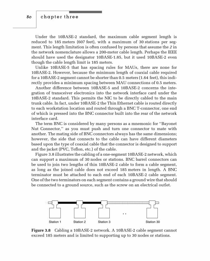
80 c h a p t e r t h r e e
Under the 10BASE-2 standard, the maximum cable segment length isreduced to 185 meters (607 feet), with a maximum of 30 stations per seg-ment. This length limitation is often confused by persons that assume the 2 inthe network nomenclature allows a 200-meter cable length. Perhaps the IEEEshould have used the designator 10BASE-1.85, but it used 10BASE-2 eventhough the cable length limit is 185 meters.
Unlike 10BASE-5 that has spacing rules for MAUs, there are none for10BASE-2. However, because the minimum length of coaxial cable requiredfor a 10BASE-2 segment cannot be shorter than 0.5 meters (1.64 feet), this indi-rectly provides a minimum spacing between MAU connections of 0.5 meters.
Another difference between 10BASE-5 and 10BASE-2 concerns the inte-gration of transceiver electronics into the network interface card under the10BASE-2 standard. This permits the NIC to be directly cabled to the maintrunk cable. In fact, under 10BASE-2 the Thin Ethernet cable is routed directlyto each workstation location and routed through a BNC T-connector, one endof which is pressed into the BNC connector built into the rear of the networkinterface card.
The term BNC is considered by many persons as a mnemonic for ‘‘BayonetNut Connector,’’ as you must push and turn one connector to mate withanother. The mating side of BNC connectors always has the same dimensions;however, the side that connects to the cable can have different diametersbased upon the type of coaxial cable that the connector is designed to supportand the jacket (PVC, Teflon, etc.) of the cable.
Figure 3.8 illustrates the cabling of a one-segment 10BASE-2 network, whichcan support a maximum of 30 nodes or stations. BNC barrel connectors canbe used to join two lengths of thin 10BASE-2 cable to form a cable segment,as long as the joined cable does not exceed 185 meters in length. A BNCterminator must be attached to each end of each 10BASE-2 cable segment.One of the two terminators on each segment contains a ground wire that shouldbe connected to a ground source, such as the screw on an electrical outlet.
Station 1 Station 2 Station 3
• •
Station 30
Figure 3.8 Cabling a 10BASE-2 network. A 10BASE-2 cable segment cannotexceed 185 meters and is limited to supporting up to 30 nodes or stations.

ethernet networks 81
The Thinnet Tap
The coaxial cable that forms the network bus must be routed directly intoeach T-connector, which in turn is mated to a node or station. This means it isnot possible to locate a node away from the BNC T-connector by connectinga single coaxial stub or drop cable between the T-connector and the node,limiting the flexibility of this network unless you employ a thinnet tap.Otherwise, the use of a single coaxial drop cable can result in the occurrenceof signal reflections that can generate transmission errors.
A thinnet tap was developed by vendors to enable individual nodes to belocated at a distance from the main 10BASE-2 network cable. This tap consistsof a tap assembly that connects to the main coaxial 10BASE-2 cable and adrop cable with two coaxial cables and the equivalent of a BNC T-adapter.When the drop cable is connected to a tap assembly it triggers a switch inthe tap, which electrically connects each side of the tap to one of the cablesin the drop cable. This action loops the signal from the top of the node andback to the other side of the tap, resulting in an unbroken network, whichfrom an electrical perspective, is the same as connecting the node via aconventional BNC T-connector. Figure 3.9 illustrates a schematic diagram ofa tap assembly.
Multifunction Transceivers
Because of the similarities between 10BASE-5 and 10BASE-2, several ven-dors introduced transceivers that support both thick and thin coaxial cable.Figure 3.10 illustrates the Universal Ethernet Transceiver manufactured by
Coaxial cable Coaxial cableTap assembly
Drop cable(two cables)
Figure 3.9 A 10BASE-2 tap assembly. Through the use of a 10BASE-2 tapassembly, it becomes possible to locate nodes at a distance from the back-bone network.

82 c h a p t e r t h r e e
Figure 3.10 Universal Ethernet Transceiver. The Universal EthernetTransceiver manufactured by Transition Engineering of Edina, Minnesota,supports both 10BASE-2 and 10BASE-5 coaxial cable connections.(Photograph courtesy of Transition Engineering, Inc.)
Transition Engineering of Edina, Minnesota. The transceiver illustrated in theupper left corner of Figure 3.10 is a 10BASE-2 transceiver. It can be convertedinto a 10BASE-5 transceiver with an adapter that converts the BNC on thethinnet transceiver into a vampire tap–type connector, as illustrated in thelower right corner of Figure 3.10.
Grounding
Depending upon the type of coaxial-based Ethernet installed, you may requirethe cable to be grounded. The 10BASE-5 specification indicates that thecoaxial cable should be grounded at one, and only one, point. In comparison,the 10BASE-2 specification indicates that thin coaxial cable may be groundedat one, and only one, point.
Regardless of the type of coaxial cable–based network you are using, it isnormally a good idea to ground the cable at one location. Doing so alleviatesthe potential for static electricity to build up. In addition, many local electricalcodes require network cabling to be grounded at one location. When grounding

ethernet networks 83
a coaxial-based network, it is also important to ensure you do so at only onelocation. Otherwise, multiple grounds on an Ethernet segment can result in arisk to equipment, shock to people, and network errors.
You can ground a network segment through the use of a coaxial cableterminator with ground wire, similar to the terminator illustrated in the lowerright portion of Figure 3.3. If you install a repeater on one end of a segment, itis important to note that most repeaters can be set up to ground or not ground.Thus, you may be able to use a repeater to ground a segment. It’s importantto note that a 10BASE-2 network will have a 50 ohm terminator at each end.Only one of the terminators should be grounded. If you ground both, althoughthe network will not completely fail, this will result in an increased error rateas well as slow data transfer on the network.
Expanding a 10BASE-2 Network
You can increase the number of stations that can be attached to a 10BASE-2network, the total network distance, or both through the use of repeaters. Aswith a 10BASE-5 network, between any two nodes there can be up to fivecable segments connected through four repeaters. Like a 10BASE-5 segment,each end of every 10BASE-2 segment must be terminated with a 50-ohmterminator, with one end of each segment grounded.
Figure 3.11 illustrates an expanded 10BASE-2 network consisting of threepopulated cable segments; two segments are used to extend the network spanby simply connecting two repeaters. The latter segments are also commonlyreferred to as interrepeater cable segments (IRCS). Each cable segment shownin Figure 3.11 requires one MAU connection to a repeater. Because thereare a maximum of 30 stations or MAU connections per segment, this meansthat segments connected by a repeater are limited to actually supporting29 workstations.
Two-Tier Cabling You can further expand a 10BASE-2 network by estab-lishing a two-tier method of cabling. Under this cabling concept, the uppertier can consist of up to 30 repeaters, connected to one another through theuse of interrepeater cable segments. These form a backbone network withoutdirect station attachments, so populated segments on the backbone have tobe connected on each segment end to a repeater. The lower tier then con-sists of repeaters connected to populated cable segments, with the lower-tierrepeater cabled to the upper-tier repeater to obtain a connection to the back-bone. Figure 3.12 illustrates the use of a two-tier cabling hierarchy that canbe used to extend a 10BASE-2 network. As in Figure 3.11, between any pairof workstations there can be a maximum of five cable segments and four

84 c h a p t e r t h r e e
R R
SS
S
R
SS
S
S
R
IRCS
IRCS
Legend:IRSC = Interrepeater cable segment
= Stations
• •
Figure 3.11 Expanding a 10BASE-2 network. Up to five cable segmentsconnected through the use of four repeaters can be used to expand a10BASE-2 network.
repeaters. Of the five cable segments, up to three can be populated, and eachpopulated segment is limited to a maximum of 30 connections, of which oneor two will be repeater connections depending upon where the cable segmentresides with respect to the interconnected network. In addition, the maximumdistance between any two stations is limited to 100 meters (328 feet), whilethe minimum distance between BNC T-connectors is 0.5 meters (1.6 feet).
Advantages and Disadvantages
Similar to a 10BASE-5 network, the use of coaxial cable for a 10BASE-2network makes it suitable for use in locations that require a high degree ofimmunity from electrical noise. Two additional advantages associated with10BASE-2 include the fact that it is easy to establish because devices are daisy-chained together, and it is relatively inexpensive. Disadvantages of 10BASE-2are also similar to the disadvantages associated with 10BASE-5. That is, a10BASE-2 network is difficult to reconfigure; a single device failure or cable
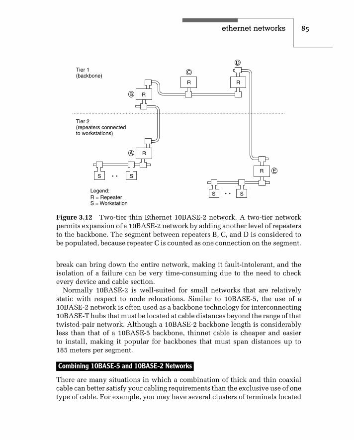
ethernet networks 85
C
R
R
R
SS
SS
R R
B
A
D
E• •
• •
Tier 1(backbone)
Tier 2(repeaters connectedto workstations)
Legend:R = RepeaterS = Workstation
Figure 3.12 Two-tier thin Ethernet 10BASE-2 network. A two-tier networkpermits expansion of a 10BASE-2 network by adding another level of repeatersto the backbone. The segment between repeaters B, C, and D is considered tobe populated, because repeater C is counted as one connection on the segment.
break can bring down the entire network, making it fault-intolerant, and theisolation of a failure can be very time-consuming due to the need to checkevery device and cable section.
Normally 10BASE-2 is well-suited for small networks that are relativelystatic with respect to node relocations. Similar to 10BASE-5, the use of a10BASE-2 network is often used as a backbone technology for interconnecting10BASE-T hubs that must be located at cable distances beyond the range of thattwisted-pair network. Although a 10BASE-2 backbone length is considerablyless than that of a 10BASE-5 backbone, thinnet cable is cheaper and easierto install, making it popular for backbones that must span distances up to185 meters per segment.
Combining 10BASE-5 and 10BASE-2 Networks
There are many situations in which a combination of thick and thin coaxialcable can better satisfy your cabling requirements than the exclusive use of onetype of cable. For example, you may have several clusters of terminals located

86 c h a p t e r t h r e e
in different geographically separated areas within a large office complex.Instead of connecting the two clusters through the use of several thin 10BASE-2 cable segments and multiple repeaters, it may be easier to install one or morethick 10BASE-5 cable segments to serve as a backbone network for attachmentto two 10BASE-2 cable segments. Thus, the ability of thick coaxial cable tosupport a longer transmission distance can eliminate or reduce the number ofrepeaters required in a combined network. In addition, a network built usingthin 10BASE-2 cable, which was originally designed for a network span under925 meters, cannot cover greater distances without mixing network media.Thus, the use of thick coaxial cable may provide the span of coverage notobtainable from the exclusive use of thin coaxial cable.
When thick and thin coaxial cable are combined to form a single cablesegment, you must consider the length of each type of cable you anticipateusing to develop a combined media cable segment. If the segment is entirelymade up of thin cable, its maximum length is 607 feet, while a cable segmentmade up of thick cable has a maximum length of 1640 feet. Thus, a combinedthin and thick cable segment should vary in length between 607 and 1640 feet.If L represents the length of a combined media cable you wish to construct,you can use the following equation to determine the maximum length ofthin cable:
thin cable = 1640 − L feet3.28
For example, suppose you want to construct a cable segment 1400 feet long.Then, the maximum length of thin 10BASE-2 cable you can use becomes:
1640 − 14003.28
= 73 feet
Thus, you could use 73 feet of 10BASE-2 cable and route that cable throughT-connectors, which are fastened to the BNC connectors on the rear of networkinterface cards. Then, you could use thick cable for the remaining 1327 feetof cable required in the cable segment.
Figure 3.13 shows an example of a combined 10BASE-5 and 10BASE-2cable segment that connects two groups of stations located at opposite endsof a building without using repeaters. At one end of the building, 10BASE-2cable is used with BNC T-connectors to connect a large number of stationsclustered together. At the other end of the building, we will assume there areonly a few stations. Thus, we would use 10BASE-5 cable and connect eachstation to the thick cable through the use of an MAU (transceiver) and an AUI(transceiver cable).
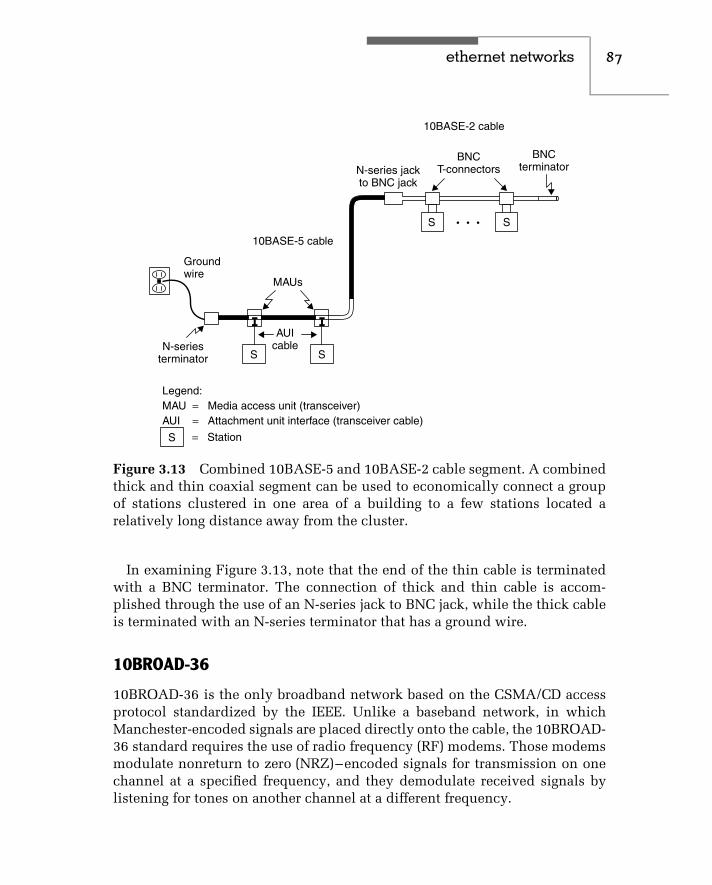
ethernet networks 87
Groundwire
MAUs
AUIcableN-series
terminator
N-series jackto BNC jack
S
S S
S
BNCT-connectors
BNCterminator
• • •
10BASE-2 cable
10BASE-5 cable
Legend:MAU = Media access unit (transceiver)AUI = Attachment unit interface (transceiver cable)
= StationS
Figure 3.13 Combined 10BASE-5 and 10BASE-2 cable segment. A combinedthick and thin coaxial segment can be used to economically connect a groupof stations clustered in one area of a building to a few stations located arelatively long distance away from the cluster.
In examining Figure 3.13, note that the end of the thin cable is terminatedwith a BNC terminator. The connection of thick and thin cable is accom-plished through the use of an N-series jack to BNC jack, while the thick cableis terminated with an N-series terminator that has a ground wire.
10BROAD-36
10BROAD-36 is the only broadband network based on the CSMA/CD accessprotocol standardized by the IEEE. Unlike a baseband network, in whichManchester-encoded signals are placed directly onto the cable, the 10BROAD-36 standard requires the use of radio frequency (RF) modems. Those modemsmodulate nonreturn to zero (NRZ)–encoded signals for transmission on onechannel at a specified frequency, and they demodulate received signals bylistening for tones on another channel at a different frequency.

88 c h a p t e r t h r e e
Cable
A 10BROAD-36 network is constructed with a 75-ohm coaxial cable, similarto the cable used in modern cable television (CATV) systems. Under the IEEE802.3 broadband standard, either single or dual cables can be used to constructa network. If a single cable is used, the end of the cable (referred to as theheadend) must be terminated with a frequency translator. That translatorconverts the signals received on one channel to the frequency assigned tothe other channel, retransmitting the signal at the new frequency. Becausethe frequency band for a transmitted signal is below the frequency band10BROAD-36 receivers scan, we say the frequency translator upconverts atransmitted signal and retransmits it for reception by other stations on thenetwork. If two cables are used, the headend simply functions as a relay point,transferring the signal received on one cable onto the second cable.
Advantages
A broadband transmission system has several advantages over a basebandsystem. Two of the primary advantages of broadband are its ability to supportmultiple transmissions occurring on independent frequency bands simulta-neously, and its ability to support a tree structure topology carrying multiplesimultaneous transmissions. Using independent frequency bands, you canestablish several independent networks. In fact, each network can be used tocarry voice, data, and video over a common cable. As for topology, broadbandpermits the use of a tree structure network, such as the structure shown inFigure 3.14. In this example, the top of the tree would be the headend; it wouldcontain a frequency translator, which would regenerate signals received atone frequency back onto the cable at another predefined frequency.
Disadvantages
Like the 10BASE-5 network, the 10BROAD-36 system uses an MAU. However,this MAU is more intelligent than a 10BASE-5 MAU, as it is responsiblefor modifying the 802.3 frame slightly for broadband transmission via amodulator. These frame modifications include the scrambling of the preamble,so that the modulation of the preamble does not result in a loss of clocking, andthe addition of a postamble to each frame. The latter assists in the detectionof the end-of-frame. Although a 10BASE-5 AUI cable can be connected toa 10BROAD-36 MAU, a 10BROAD-36 MAU obviously cannot be used witha 10BASE-5 network. However, the design specifications of the 10BROAD-36 network enable this network to support the connection of CSMA/CD

ethernet networks 89
HE
Legend:
HE = Headend
Figure 3.14 Broadband tree topology support. The headend receives trans-missions at one frequency and regenerates the received signals back onto thenetwork at another predefined frequency.
baseband equipment, and also provide a large degree of compatibility andinteroperability with baseband systems.
The higher noise immunity of 75-ohm coaxial cable permits a 10BROAD-36network to span 3600 meters, making this medium ideal for linking buildingson a campus. In addition, the ability of 10BROAD-36 to share channel spaceon a 75-ohm coaxial cable permits organizations that have an existing CATVsystem, such as one used for video security, to use that cable for part or allof their broadband CSMA/CD network. Although these advantages can besignificant, the cost associated with more intelligent MAUs and RF modemshas limited the use of broadband primarily to campus environments thatrequire an expanded network span. In addition, the rapid development andacceptance of 10BASE-T and later twisted-pair-based Fast Ethernet and thedecline in the cost of fiber cable to extend the span of 10BASE-T networkshave severely limited what many people once anticipated as a promisingfuture for 10BROAD-36 networks.
1BASE-5
The 1BASE-5 standard was based on AT&T’s low-cost CSMA/CD network,known as StarLan. Thus, 1BASE-5 is commonly referred to as StarLan,

90 c h a p t e r t h r e e
although AT&T uses that term to refer to CSMA/CD networks operatingat both 1 and 10 Mbps using unshielded twisted-pair cable. The latter isconsidered the predecessor to 10BASE-T.
The 1BASE-5 standard differs significantly from Ethernet and 10BASE-5standards in its use of media and topology, and in its operating rate. The1BASE-5 standard operates at 1 Mbps and uses UTP wiring in a star topology;all stations are wired to a hub, which is known as a multiple-access unit(MAU). To avoid confusion with the term media access unit, which also hasthe same abbreviation, we will refer to this wiring concentrator as a hub.
Topology
Each station in a 1BASE-5 network contains an NIC, cabled via UTP on apoint-to-point basis to a hub port. The hub is responsible for repeating signalsand detecting collisions. As we will shortly note, this cabling configurationrepresents a topology supported by two succeeding versions of Ethernet,10BASE-T and 100BASE-T networks.
The maximum cabling distance from a station to a hub is 250 meters; upto five hubs can be cascaded together to produce a maximum network spanof 2500 meters. The highest-level hub is known as the header hub, and itis responsible for broadcasting news of collisions to all other hubs in thenetwork. These hubs, which are known as intermediate hubs, are responsiblefor reporting all collisions to the header hub.
Usage
AT&T’s 1-Mbps StarLan network, along with other 1BASE-5 systems, initiallyreceived a degree of acceptance for use in small organizations. However,the introduction of 10BASE-T, which provided an operating rate ten timesthat obtainable under 1BASE-5, severely limited the further acceptance of1BASE-5 networks.
The growth in the acceptance of 10BASE-T resulted in economies of scalein the manufacture of 10BASE-T hubs and network interface cards. This,in turn, enabled vendors to match or exceed price cuts of other vendors.One key result of this situation was the ability of end users to obtain alow-cost, high-performance local area networking capability through the useof 10BASE-T equipment. Needless to say, 10BASE-T became the preferrednetwork technology of both small and large organizations during the early1990s, and it essentially replaced the use of 1BASE-5.

ethernet networks 91
10BASE-T
In the late 1980s, a committee of the IEEE recognized the requirement oforganizations for transmitting Ethernet at a 10-Mbps operating rate over low-cost and readily available unshielded twisted-pair cable. Although severalvendors had already introduced equipment that permitted Ethernet signalingvia UTP cabling, such equipment was based on proprietary designs and wasnot interoperable. Thus, a new task of the IEEE was to develop a standard for802.3 networks operating at 10 Mbps using UTP cable. The resulting standardwas approved by the IEEE as 802.3i in September 1990, and is more commonlyknown as 10BASE-T, with the T referencing the use of twisted-pair wire.
UTP Use
The 10BASE-T standard supports an operating rate of 10 Mbps at a distanceof up to 100 meters (328 feet) over 100 ohm Unshielded Twisted-Pair (UTP)cable without the use of a repeater. The UTP cable requires two pairs oftwisted wire. One pair is used for transmitting, while the other pair is used forreceiving. Each pair of wires is twisted together, and each twist is 180 degrees.Any electromagnetic interference (EMI) or radio frequency interference (RFI)is therefore received 180 degrees out of phase; this theoretically cancels outEMI and RFI noise while leaving the network signal. In reality, the wirebetween twists acts as an antenna and receives noise. This noise receptionresulted in a 100-meter cable limit, until repeaters were used to regeneratethe signal.
Because UTP cable previously installed in commercial buildings containseither three or four wire pairs, the RJ-45 jack used with 10BASE-T has eight-pin connectors. However, 10BASE-T uses two pairs of wires, and thus onlyfour pins are actually used. Table 3.2 compares the 10BASE-T pin numberswith the RJ-45 jack numbers and indicates the signal names of the pins usedwith 10BASE-T UTP cable.
Although 10BASE-T was designed to support transmission distances of upto 100 meters under the Electronic Industry Association/TelecommunicationsIndustry Association (EIA/TIA) cabling standard (previously described inChapter 2), the cabling distance consists of three segments. The first segment,which can be up to 90 meters in length, runs from a patch panel in a wiringcloset to a wall plate in an office. The second and third segments, which canbe up to a total of 10 meters in length, allow patch cables at each end of thelink while restricting signal loss on the total of three interconnected segments.The actual cable standard defined by the EIA/TIA for 10BASE-T is based uponthe signaling rate of the network and not the type of network. Under EIA/TIA

92 c h a p t e r t h r e e
TABLE 3.2 10BASE-T Wiring Sequence
10BASE-TPin #
RJ-45Jack #
10BASE-TSignal Name
1 1 Transmit Data +2 2 Transmit Data −3 3 Receive Data +— 4 Not used
— 5 Not used
6 6 Receive Data −— 7 Not used
— 8 Not used
cable standards, which were described in Chapter 2, category 3 cable, whichprovides support for a signaling rate up to 16 MHz, must be used in a 10BASE-T network. However, it is quite common for most organizations installing10BASE-T today to use category 5 cabling, which supports transmission upto 100 MHz. This allows an organization to upgrade to a higher-speed LANwithout having to replace their cabling infrastructure.
Link Integrity Test
Each version of Ethernet continuously monitors the received data path as amechanism for determining if the link is operating correctly. To ensure theother station has a signal to receive even when there is no frame to receive, alink integrity test signal is transmitted during periods where there is no actualnetwork traffic. Through the transmission of link test pulses a sufficient levelof activity will occur on the receive data path to provide the receiver with theability to check the integrity of the link.
Network Components
A 10BASE-T network can be constructed with network interface cards, UTPcable, and one or more hubs. Each NIC is installed in the expansion slot ofa computer and wired on a point-to-point basis to a hub port. One exceptionto the preceding is built-in Ethernet chipsets now commonly added to laptopand notebook motherboards. When using such computers you only need towire them to a hub port to become a participant on a network. When all of the
ethernet networks 93
ports on a hub are used, one hub can be connected to another to expand thenetwork, resulting in a physical star, logical bus network structure.
The design of a 10BASE-T hub centric–based network provides a wiringscheme that can tolerate wiring failures much better than a bus-based coaxialcable network. For example, if a coaxial cable is broken at any point, the entirenetwork segment fails. In comparison, the star-wiring topology of a 10BASE-Thub-based network eliminates the single point of failure of a common cable.This is because the failure of a cable between a hub port and a workstationwill not affect other workstations. Although the hub is a central point offailure, it is normally a very reliable device, and you can probably expectnumerous cable failures from everyday office activity to occur before a hubfailure occurring.
Network Interface Cards Most 10BASE-T network interface cards containmultiple connectors, which enable the card to be used with different types of802.3 networks. For example, the NIC illustrated in Figure 3.15 includes anRJ-45 jack as well as BNC and DB-15 connectors. The RJ-45 jack supports thedirect attachment of the NIC to a 10BASE-T network, while the BNC connectorpermits the NIC to be mated to a 10BASE-2 T-connector. The DB-15 connectorenables the NIC to be cabled to a transceiver, and is more commonly referredto as the NIC’s attachment unit interface (AUI) port.
Depending on the type of connectors built into your NIC, you may haveseveral options to consider for connecting the NIC to a specific type of IEEE802.3 network. For example, assume that your NIC is limited to supportinga thick or thin coaxial cable connection. In that case, you can still use theNIC to connect to a 10BASE-T network, using a transceiver similar to the oneillustrated in Figure 3.16.
Figure 3.16 illustrates a 10BASE-T Ethernet transceiver manufactured byTransition Engineering, Inc. This transceiver allows you to connect an existingthick or thin 10BASE-5 or 10BASE-2 NIC’s DB-15 AUI port to a 10BASE-Tnetwork. To do this, you would cable the NIC’s DB-15 AUI port to the DB-15connector at the left of the transceiver. Then, you would cable the transceiverto a hub port using UTP.
Hub The wiring hub in a 10BASE-T network functions as a multiportrepeater: it receives, retimes, and regenerates signals received from anyattached station. The hub also functions as a filter: it discards severelydistorted frames.
All hubs that conform to IEEE 10BASE-T specifications perform a core setof tasks in addition to receiving and regenerating signals. 10BASE-T hubs test

94 c h a p t e r t h r e e
Figure 3.15 Multiple-media network interface card. Some multiple-medianetwork interface cards, such as the one illustrated, support the direct attach-ment to UTP and thin coaxial cable, while the DB-15 connector permits thecard to be cabled to an MAU connected to thick coaxial cable.
Figure 3.16 Transition Engineering 10BASE-T transceiver. With a 10BASE-Ttransceiver, you can connect existing thick or thin 10BASE-5 or 10BASE-2NICs to a 10BASE-T network. (Photograph courtesy of Transition Engineer-ing, Inc.)

ethernet networks 95
each port connection, detect and handle excessive collisions, and ignore datathat exceeds the maximum 802.3 frame size.
A 10BASE-T hub tests the integrity of the link from each hub port toa connected station by transmitting a special signal to the station. If thedevice doesn’t respond, the hub will automatically shut down the port andmay illuminate a status light-emitting diode (LED) to indicate the status ofeach port.
Hubs monitor, record, and count consecutive collisions that occur on eachindividual station link. Because an excessive number of consecutive collisionswill prevent data transfer on all of the attached links, hubs are required tocut off or partition any link on which too many collisions have occurred.This partitioning enables the remainder of the network to operate in situa-tions where a faulty NIC transmits continuously. Although the IEEE 802.3standard does not specify a maximum number of consecutive collisions,the standard does specify that partitioning can be initiated only after 30 ormore consecutive collisions occur. Thus, some hub vendors initiate partition-ing when 31 consecutive collisions occur, while other manufacturers use ahigher value.
Another operating function of 10BASE-T hubs is to ignore continuous datatransmissions in which the frame length exceeds the maximum length of1518 bytes. That length does not include the 8 byte preamble, which resultsin the maximum length of an Ethernet frame being 1518 bytes when insidean adapter and 1528 bytes when flowing on the wire. Such excessive lengthframes usually result from collisions and are referred to as jabbering. Mosthubs also partition a jabbering port, and some hubs include a jabber indicatorLED in addition to a partition status LED on each port.
Although a wiring hub is commonly referred to as a concentrator, this termis not technically correct. A 10BASE-T wiring hub is a self-contained unit thattypically includes 8, 10, or 12 RJ-45 ports for direct connection to stations,and a BNC and/or DB-15 AUI port for expanding the hub to other networkequipment. The BNC and AUI ports enable the 10BASE-T hub to be connectedto 10BASE-2 and 10BASE-5 networks, respectively. For the latter, the AUIport is cabled to a 10BASE-5 MAU (transceiver), which is tapped into thick10BASE-5 coaxial cable. One 10BASE-T hub can be connected to another witha UTP link between RJ-45 ports on each hub.
Figure 3.17 illustrates the connectors on a typical 10BASE-T hub. Onsome hubs, one RJ-45 jack is labeled uplink/downlink for use in cas-cading hubs, while other vendors permit any RJ-45 port to be used forconnecting hubs.

96 c h a p t e r t h r e e
AC power cordconnector
Standard thickwireconnector
1 2 3 4 5 6 7 8 9 10 11 12 Ethernet
815
19
RJ-45 modularjacks for terminal
connectionsThinwire
BNC connector
Figure 3.17 10BASE-T hub connectors. In addition to 8, 10, or 12 RJ-45modular jacks for terminal connections, most 10BASE-T hubs contain a BNCand DB-15 port to permit attachment to thin and thick backbone networks.
13
2
4
5
6
7
8
Figure 3.18 A 10BASE-T single hub–based network. A hub functions as amultiport repeater, regenerating datareceived on one port to all other ports.
Figure 3.18 illustrates the use of a 10BASE-T hub to form a single 10BASE-Tnetwork segment. Note that the twisted-pair connections allow workstationsto be connected from different locations with respect to the hub, providingmore cabling flexibility than bus-based Ethernet networks.
In examining Figure 3.18 note that station 1 is shown transmitting data tothe hub. As previously mentioned, the hub functions as a repeater. Thus, it isshown retransmitting data received on one port back to all stations connectedto other ports on the hub.
Wiring Requirements There are two types of wiring used with 10BASE-Tnetworks — straight-through and crossover. Each type of wiring is used tosupport a different type of equipment connection, thus it is important tounderstand where each type of wiring is used.
Straight-through Wiring The wiring used with UTP cable for connectinga 10BASE-T hub to the network interface card consists of straight-through
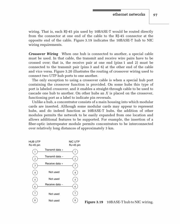
ethernet networks 97
wiring. That is, each RJ-45 pin used by 10BASE-T would be routed directlyfrom the connector at one end of the cable to the RJ-45 connector at theopposite end of the cable. Figure 3.19 indicates the 10BASE-T hub to NICwiring requirements.
Crossover Wiring When one hub is connected to another, a special cablemust be used. In that cable, the transmit and receive wire pairs have to becrossed over; that is, the receive pair at one end (pins 1 and 2) must beconnected to the transmit pair (pins 3 and 6) at the other end of the cableand vice versa. Figure 3.20 illustrates the routing of crossover wiring used toconnect two UTP hub ports to one another.
The only exception to using a crossover cable is when a special hub portcontaining the crossover function is provided. On some hubs this type ofport is labeled crossover, and it enables a straight-through cable to be used tocascade one hub to another. On other hubs an X is placed on the crossover,functioning port as a label to indicate pin reversals.
Unlike a hub, a concentrator consists of a main housing into which modularcards are inserted. Although some modular cards may appear to representhubs, and do indeed function as 10BASE-T hubs, the addition of othermodules permits the network to be easily expanded from one location andallows additional features to be supported. For example, the insertion of afiber-optic interrepeater module permits concentrators to be interconnectedover relatively long distances of approximately 3 km.
HUB UTPRJ-45 pin
NIC UTPRJ-45 pin
Transmit data +
Transmit data −
Receive data +
Receive data −
Not used
Not used
Not used
Not used
1
2
3
4
5
6
7
8
1
2
3
4
5
6
7
8 Figure 3.19 10BASE-T hub to NIC wiring.

98 c h a p t e r t h r e e
1
2
3
4
5
6
7
8
1
2
3
4
5
6
7
8
Wire routingSignal
Transmit data +
Transmit data −
Receive data +
Receive data −
Not used
Not used
Not used
Not used
UTPRJ-45 pin
UTPRJ-45 pin
Figure 3.20 A crossover cable isrequired to connect hubs together.
Wiring Considerations
Because 10BASE-T uses RJ-45 jacks and telephone wire is commonly available,we may be tempted to use a silver satin color patch cable to connect aworkstation to a hub port. Don’t! The reason you should stay away from silversatin wire used to connect telephones to jacks is because they do not havetwisted pairs inside. The lack of twisted pair means that the cable becomesa long antenna and can result in excessive crosstalk as transmit and receivesignals interface with one another. In addition, excessive crosstalk signalscan appear as simultaneous traffic, which can result in the false triggeringof collision detection circuitry. The result of this triggering will be ‘‘latecollisions,’’ a term used to indicate collisions that are detected too late in thetransmission of a frame to permit near immediate retransmission of the frame.Instead, the loss of the frame will be detected by application software andthe resulting retransmission will be considerably slower. You can eliminate amajor cause of the previously described problems by restricting your use ofcable to twisted-pair rated for use for an applicable version of Ethernet. Thatis, use cat 3 cable for 10BASE-T and cat 5 for 100BASE-T, while cat 5e or cat 6should be used for Gigabit Ethernet.
Expanding a 10BASE-T Network
A 10BASE-T network can be expanded with additional hubs once the numberof stations serviced uses up the hub’s available terminal ports. In expandinga 10BASE-T network, the wiring that joins each hub together is considered torepresent a cable segment, while each hub is considered as a repeater. Thus,

ethernet networks 99
under the 802.3 specification, no two stations can be separated by more thanfour hubs connected together by five cable segments. In addition, two of thefive segments cannot be populated, which results in 10BASE-T adhering tothe previously described 5-4-3 rule.
Figure 3.21 illustrates the expansion of a 10BASE-T network through the useof five hubs. Note that the connection between station A and station B traversesfive segments and four hubs, and does not violate IEEE 802.3 connectionrules. Because the maximum span of a 10BASE-T network is 100 meters persegment times five segments, or 500 meters, it is quite common for 10BASE-T networks to use a 10BASE-5 or even a 10BASE-2 cable backbone. As inFigure 3.12, in which a 10BASE-5 cable provided a backbone for a 10BASE-2 network, either 10BASE-2 or 10BASE-5 cable can be used to support anextension of a 10BASE-T network. In such situations, the AUI port of a10BASE-T hub is connected to a MAU (transceiver) connected to the 10BASE-5 (thick coaxial) cable, or the BNC connector is mated to a thin coaxialcable’s T-connector. Another reason for using a thin or thick coaxial cablefor a backbone is that you can thereby avoid the four-hub cascading limitof 10BASE-T. For example, if you cabled ten hubs to a 10BASE-5 coaxial
A
B
Legend: = Stations
Figure 3.21 Expanding a 10BASE-T network. No two stations can be sepa-rated by more than four hubs in a 10BASE-T network.

100 c h a p t e r t h r e e
cable backbone, each station would traverse at most two hubs, and wouldthus comply with the IEEE rules. In comparison, you could not connect morethan five hubs together in a conventional 10BASE-T network because of IEEE802.3 rules.
Full-Duplex Operations
Because 10BASE-T wiring has separate transmission and receive signal pathsit can instantly detect a collision as data is transmitted. However, if nocollisions are possible, the ability to have simultaneously active signal pathsis wasted. Because the direct connection of stations to a switch port precludesthe possibility of a collision, 10BASE-T full duplex became possible ina switch environment, a network topology that will be covered later inthis book.
3.3 Use of Fiber-Optic Technology
An addition to Ethernet, which allows transmission via pulses of lightinstead of electrical current, is known as FOIRL, an acronym that standsfor fiber-optic repeater link. Although FOIRL is not an Ethernet network,this specification governs the transmission of Ethernet across dual-fibercable — one fiber is used for the transmission of data in the form of lightpulses, while the second fiber is used for the reception of data in the form oflight pulses.
The fiber-optic repeater link (FOIRL) represents one of two fiber-optic spec-ifications developed to support different types of Ethernet networks operatingat 10 Mbps. The second standard, referred to as 10BASE-F, is designed tointeroperate with older FOIRL-based equipment and provides backward com-patibility with the older specification. Both standards provide immunity fromelectrical hazards to include electromechanically generated noise and light-ning, enabling networks to be extended through gasoline refineries and otherareas where metallic media would be banned.
The use of fiber permits you to support multiple Ethernet segments atdistances up to 2000 meters (6600 feet) from one another. At a remote locationconnected through the use of fiber-optic technology, you can connect a singlestation directly using a fiber transceiver, or you can connect a 10BASE-T orfiber hub and support multiple stations. You would use the AUI port of thehub to provide a connection via a standard transceiver to different types ofEthernet networks, while you would use an optical transceiver to provide aconnection to the dual-fiber cable.

ethernet networks 101
FOIRL
The older IEEE 802.3 FOIRL standard enables a fiber link segment to be up to1000 meters between two repeaters while the more recent 10BASE-F standarddoubles the distance to 2000 meters. The greater distance is, however, onlyobtainable when 10BASE-F repeaters are used at both ends. When 10BASE-Fis mixed with FOIRL, the maximum length of the segment is reduced to1000 meters.
Other differences between FOIRL and 10BASE-F include the names asso-ciated with different fiber-optic components associated with each networktechnology and the optical transmit power levels, receive sensitivity, andpower loss associated with each optical technology. In our examination ofthe use of 10-Mbps fiber-optic media, we will first turn our attention to theuse of FOIRL components and, when appropriate, discuss its similaritiesand differences with respect to the more modern 10BASE-F standard. Oncewe complete our examination of FOIRL, we will then turn our attention to10BASE-F.
Optical Transceiver
The optical transceiver is common to both FOIRL and 10BASE-F, with onlythe optical power transmit and receive levels differing between the twospecifications. An optical transceiver consists of a pulse-generating LED,a photodetector, and associated transmit and receive circuitry. Transmitcircuitry turns the LED on and off to convert electrical voltages represent-ing data into a series of light pulses for transmission over the fiber. Thephotodetector recognizes received light pulses, while the receive circuitrygenerates electrical voltages and shapes pulses to correspond to the receivedlight pulses.
Today, you can purchase a fiber network access unit (NAU), an opticaltransceiver mounted on an adapter card for installation in the system unit ofa personal computer, for less than $150. A second type of optical transceiverused on Ethernet networks is built into fiber hubs, the use of which will becovered next in this section. This type of optical transmitter may be designedto share the use of a common power source and circuitry, resulting in aper-port hub cost usually less than the cost of a fiber adapter.
Fiber Hubs
Under the original FOIRL specification the use of a fiber-optic segment wasonly applicable between repeaters. This meant that you could not actually

102 c h a p t e r t h r e e
connect a distant station directly to a port on a hub. While industry waited forthe development of 10BASE-F standards several vendors, including AT&T,incorporated FOIRL capability into hubs to provide network customers withadditional capabilities while awaiting the ability to manufacture 10BASE-Fproducts once appropriate standards were promulgated. Thus, when wediscuss the operation of FOIRL ports in hubs, you should note that this actu-ally references proprietary equipment, because that standard only governedtransmission on fiber between repeaters.
A fiber hub is a special type of hub that contains a number of FOIRL ports,one AUI port, and usually one or more 10BASE-T ports. For example, AT&T’soriginal StarLan fiber hub contained six FOIRL ports, one 10BASE-T port, andone AUI port. In comparison, Transition Engineering’s Model 1050 fiber-optichub contains 12 FOIRL ports and one AUI interface port.
In effect, a fiber hub is a grouping of fiber NAUs and one or more 10BASE-Tand/or AUI ports. Thus, you can use a fiber hub to support several extended-distance Ethernet connections, and then link those connections directly to a10BASE-T network with a 10BASE-T port built into the fiber hub, or indirectlyto any type of Ethernet network with an AUI port built into the fiber hub.A more modern 10BASE-F hub consists of a series of fiber link (10BASE-FL)ports, with the key difference between 10BASE-F and FOIRL hubs being theoptical transmit power and optical receiver sensitivity supported by each porton each hub.
Fiber Adapter
A third type of hardware product used with FOIRL is a fiber adapter. Thefiber adapter is a media conversion device that converts between twisted-pair and fiber-optic cable. This device extends the transmission distancebetween a wire hub and an attached workstation — or another 10BASE-T wirehub — from 100 meters (328 feet) to 1000 meters. If a 10BASE-F fiber adapteris used with a 10BASE-F-compliant hub port, the transmission distance isextended to 2000 meters. For both FOIRL and 10BASE-F, unless the fiberadapter is connected directly to a fiber hub, an adapter is required at each endof an extended fiber link.
Wire and Fiber Distance Limits
Figure 3.22 illustrates the transmission distance limits associated with the useof 10BASE-T and FOIRL-compliant fiber hubs and fiber adapters. Note that afiber network access unit installed in the system unit of a PC can communicate

ethernet networks 103
Fiberhub
Wirehub
Wirehub
Wirehub
Wirehub
Wire100mmax
Wire 15mmax
Wire 15mmax
Wire100mmax
Fiber 2 km max
Fiber 2 km max
Wire closet
Wire 100m max UTP NAUin PC
Fiberadapter
Fiberadapter
Fiber NAUin PC
Figure 3.22 10BASE-T and FOIRL transmission distance limits.
up to 1000 meters via fiber-optic cable, either directly into a fiber hub or to afiber adapter connected to a wire hub. Also note that in the upper right cornerof Figure 3.22, it was assumed that three 10BASE-T wire hubs were installedin a wire closet. If that wire closet is located on a low floor in a building andyour organization leases another floor hundreds of feet above the wire closetfloor, the use of fiber-optic cable provides a mechanism to link two networksegments together. Similarly, the wire closet shown in the illustration couldbe in one building on a university campus, with fiber used to connect thatbuilding to another building. This use of fiber-optic cable not only extendsthe transmission distance of the network, but also eliminates the possibilityof electromagnetic interference (EMI), because fiber cable is immune to EMI.
The distance limitation associated with the use of FOIRL has nothing todo with the transmission constraints associated with optical signals. Instead,the FOIRL distance limitation is related to the timing constraints in the IEEE802.3 standard.
Because the FOIRL standard is limited to point-to-point connections, whenused to interconnect two 10BASE-2 networks you must consider the cablelength of each segment. For example, assume you have two 10BASE-2networks located in different areas on a large factory floor, as illustrated

104 c h a p t e r t h r e e
OR
OR
OR
Legend:
= Workstation
= Optical repeater
Figure 3.23 Connecting 10BASE-2 networks using a fiber-optic interre-peater link.
in Figure 3.23. If segment A has a cable length of 300 meters and seg-ment B has a cable length of 500 meters, what is the maximum FOIRLcable length? Because the maximum cabling distance of a 10BASE-2 net-work is 2500 meters, subtracting the sum of the cable lengths from thatcable constraint (2500 − (300 + 500)) results in a maximum fiber-optic link of1700 meters.
Another constraint you must consider is the Ethernet repeater limitation.Ethernet limits any interconnected network to a maximum of four repeatersbetween any two nodes. Thus, when considering the use of fiber-opticrepeaters, you must take into consideration the maximum network lengthas well as the number of repeaters that can be placed between nodes. As wewill shortly note, under 10BASE-F a mechanism exists that allows the 5-4-3rule to be exceeded.
10BASE-F
The development and promulgation of the IEEE 10BASE-F standard offi-cially provided network users with the ability to use fiber-optic hubs. Aspreviously noted in the section covering the FOIRL specification, vendorsintegrated FOIRL capability into hubs; however, the actual standard thatofficially provided this capability was the 10BASE-F standard.
Under the 10BASE-F standard, which actually represents a set of fiber-optic media standards, three types of segments for optical transmission weredefined. Those segments include 10BASE-FL, 10BASE-FB, and 10BASE-FP,each of which we will now examine.
10BASE-FL
The 10BASE-FL standard provides a fiber-optic link segment that can beup to 2000 meters in length, providing that only 10BASE-FL equipment is

ethernet networks 105
used at both ends of the segment. Otherwise, the mixing of 10BASE-FL andFOIRL equipment reduces the maximum length of the optical segment to1000 meters.
The development of the 10BASE-FL standard was intended as a replace-ment for the older FOIRL specification. Unlike FOIRL that was restricted toproviding an optical connection between repeaters, 10BASE-FL enables anoptical segment to be routed between two workstations, two repeaters, orbetween a workstation and a repeater port.
The actual connection of a copper-based network node to a 10BASE-FL seg-ment can be accomplished in one of two ways. First, a stand-alone fiber-opticMAU (FOMAU) can be connected via the 15-pin AUI connector on a networkadapter to provide an electrical-to-optical conversion capability. A secondmethod is to use a 10BASE-T/FL converter. The latter is used when only a10BASE-T port is available on a NIC. Both the 10BASE-FL FOMAU and the10BASE-T/FL converter include two fiber-optic connectors, one for transmit-ting and one for receiving data. Some 10BASE-T/FL converters include twoRJ-45 connectors that provide a high degree of cabling flexibility. One RJ-45connector functions as a crossover cable and allows hub-to-hub communica-tions via optical media, while the second connector is for workstations thatuse a straight-through connection.
The top portion of Figure 3.24 illustrates the connection of a workstation toa 10BASE-FL FOMAU via a 15-pin AUI connector. The lower portion of thatillustration shows the use of a 10BASE-T/FL converter. Both devices provideyou with the ability to transmit up to 2000 meters via a fiber link when a10BASE-F-compliant optical device is at the other end of the optical link.
In addition to the use of a 10BASE-FL FOMAU and 10BASE-T/FL con-verter, other types of converters have been developed to extend a fiber-optictransmission capability to other types of Ethernet networks. For example, a10BASE-2/FL converter enables you to extend the transmission distance of a10BASE-2 network via a fiber-optic connection.
The creation of a 10BASE-F optical hub is accomplished by the inclusion oftwo or more FOMAUs in the hub. This results in the hub becoming an opticalrepeater, which retransmits data received on one port onto all other ports.Under the 10BASE-F standard you can use multiple 10BASE-FL connectionsto connect several individual workstations at distances up to 2000 meters to acommon hub equipped with FOMAU ports.
Network Media
When examining the potential use of a converter or a FOMAU, it is importantto verify the type of optical media supported. Multimode fiber (MMF) is

106 c h a p t e r t h r e e
EthernetNIC
AUI cable 10BASE-FL TXFOMAU RX
Opticalcable
(a) Using a fiber-optic MAU (FOMAU)
EthernetNIC
UTP cable
10BASE-T/FL
Opticalcable
(b) Using a 10BASE-T/FL converter
HW
Figure 3.24 Options for connection of a workstation to a 10BASE-FLsegment.
commonly used, with the most popular type of fiber having a 62.5-micron (µ)fiber-optic core and a 125-µ outer cladding. This type of multimode fiberis referenced by the numerics 62.5/125 µ. The wavelength of light used ona 62.5/125-µ MMF fiber link is 850 nanometers (nm), and the optical lossbudget, a term used to reference the amount of optical power lost throughattenuation, should not exceed the range 9.7 to 19.0 dB, with the exact amountdependent upon the type of fiber used. Table 3.3 provides a comparison of theoptical attenuation for 10BASE-FL and FOIRL for six types of multimode fiber.In examining the entries in Table 3.3, you will note that 10BASE-FL has ahigher loss budget than FOIRL for each type of multimode fiber. This explainswhy the transmission distance of 10BASE-FL optical repeaters exceeds thedistance obtainable using FOIRL repeaters.
The connectors used on the previously described multimode fiber arereferred to as ST connectors. The ST connector represents a spring-loadedbayonet connector whose outer ring locks onto the connection similar tothe manner by which BNC connector’s junction on 10BASE-2 segments. Tofacilitate the connection process, an ST connector has a key on the innersleeve and an outer bayonet ring. To make a connection you would line upthe key on the inner sleeve of the ST plug with a slot on an ST receptacle,push the connector inward and then twist the outer bayonet ring to lock the

ethernet networks 107
TABLE 3.3 Comparing the Loss Budget (Optical Attenuation) of 10BASE-FLand FOIRL
Multimode, gradedindex fiber size (µm)
50/125 50/125 50/125 62.5/125 83/125 100/140
Numerical aperture .20 .21 .22 .275 .26 .30
10BASE-FLLoss budget (dB)
9.7 9.2 9.6 13.5 15.7 19.0
FOIRLLoss budget (dB)
7.2 6.7 7.1 11.0 13.2 16.5
connection in place. This action not only results in a tight connection but, inaddition, provides a precise alignment between the two portions of fiber-opticcable being joined.
It is important to note that the optical loss depends upon several factors.First, the length of the fiber governs optical loss, with a typical fiber illuminatedat 850 nm having a loss between 4 dB and 5 dB per 1000 meters. Second, theseof more connectors results in a higher optical loss. Third and perhaps mostimportant to note since this is easy to rectify, if your connectors or fiber splicesare poorly made or if dirt, finger oil or dust resides on connector ends, youwill obtain a higher level of optical loss than necessary.
10BASE-FB
A second 10BASE-F specification is 10BASE-FB, with the B used to denotea synchronous signaling backbone segment. The 10BASE-FB specificationenables the limit on the number of repeaters previously described in the 5-4-3rule section to be exceeded. A 10BASE-FB signaling repeater is commonlyused to connect repeater hubs together into a repeated backbone networkinfrastructure that can span multiple 2000-m links.
10BASE-FP
A third 10BASE-F specification was developed to support the connectionof multiple stations via a common segment that can be up to 500 metersin length. Referred to as 10BASE-FP, the P references the fact that the endsegment is a fiber-passive system. Under the 10BASE-FP specification a singlefiber-optic passive-star coupler can be used to connect up to 33 stations. Thosestations can be located up to 500 meters from a hub via the use of a sharedfiber segment.

108 c h a p t e r t h r e e
Although 10BASE-FP provides a clustering capability that might representa practical networking solution to the requirements of some organizations, aswell as reduce the cost associated with the use of multiple individual opticalcables, most organizations prefer to link hubs together. Doing so also allowsthe use of a single pair of optical cables; however, the transmission distanceto the cluster is then extended to 2000 meters.
3.4 High-Speed Ethernet
To differentiate Gigabit and 10 Gbps Ethernet from other versions of Ethernetwhose operating rates exceed 10 Mbps but have a maximum operating rateone-tenth that of Gigabit, those versions of Ethernet that operate at or below100 Mbps were classified as high-speed Ethernet and are covered in thissection. This enables Gigabit and 10 Gbps Ethernet to be covered as a separateentity in Section 3.5.
There are three broad categories into which high-speed Ethernet networksfall. The first two types of high-speed Ethernet networks are represented by dejure standards for operations at 100 Mbps, while the third standard representsan extension to 10BASE-T that operates at 16 Mbps. As discussed in Chapter 2,the IEEE standardized two general types of 100-Mbps Ethernet networks, withthe 802.3µ standard defining three types of 100-Mbps CSMA/CD networks,while the 802.12 standard defines a demand-priority operation that replacesthe CSMA/CD access protocol. The third high-speed Ethernet network isconsidered as a high-speed network only when compared with the operatingrate of Ethernet networks developed before 1992. This type of network, referredto as isochronous Ethernet (isoENET), operates at 16 Mbps. This section willfocus upon obtaining a overview of the operation and use of each of thesethree types of Ethernet networks.
Isochronous Ethernet
Isochronous Ethernet, or isoENET, represents an extension to 10BASE-Ttechnology. Isochronous Ethernet adds time-sensitive multimedia supportthrough an addition of 6.144 Mbps of isochronous bandwidth to existing 10-Mbps 10BASE-T Ethernet. Here, the term isochronous references a series ofrepetitive time slots used for the transmission of constant bit-rate services atthe physical bit-transmission level.
Although isoENET received a considerable degree of publicity during theearly 1990s, it never received any significant degree of commercial accep-tance. This was probably due to the development of Fast Ethernet, which
ethernet networks 109
provided over six times the transmission capacity of isoENET. However,because isoENET provided time slots for the transmission of time-sensitiveinformation, its design in effect provided a Quality of Service (QoS) capabilitythat is worth examining.
Isochronous Ethernet dates to 1992, when National Semiconductor andIBM, with support from Apple Computer, submitted the basics of isoENETto the IEEE 802.9 Integrated Services Local Area Networks working group.Better known by its trade names isoEthernet and isoENET, this technique wasstandardized by the IEEE as standard 802.9a, with the official designationIntegrated Service Local Area Network (ISLAN16-T). Here, the T in the abbre-viation denotes its capability to operate over twisted-pair wiring, while the16 references its operating rate. In comparison with other Ethernet LANs thatare asynchronous, isoENET was developed to support the 8-KHz samplingclock used as a worldwide standard for voice transmission. This synchro-nization capability was layered on top of the 10-Mbps 10BASE-T operatingrate, enabling isoENET to support real-time communications in addition toconventional 10BASE-T asynchronous LAN transmission.
Isochronous Ethernet represented a hybrid type of Ethernet network, com-bining standard 10-Mbps 802.3 10BASE-T with a 6.144-Mbps isochronousnetworking capability. The 6.144 Mbps of additional bandwidth was designedto accommodate 96 integrated services digital network (ISDN) B-channels,either individually or in multiple combinations of N × 64 Kbps. For example,a videoconference requiring 128 Kbps of bandwidth would be assigned two 64-Kbps channels, while digitized voice that requires 64 Kbps when pulse codemodulation (PCM) is used for digitization would be assigned one channel.
Besides being designed to support 96 ISDN B-channels, the isochronousbandwidth supported one 64-Kbps ISDN D-channel for signaling and one96-Kbps ISDN M-channel used to support ISDN maintenance functions.Figure 3.25 illustrates the allocation of isoENET bandwidth.
IsoENET replaced the Manchester encoding used by 10BASE-T with a 4B/5Bencoding scheme, which represents the data encoding method used by theANSI X3T9.5 FDDI standard. Under 4B/5B coding, each octet of data is splitinto two four-bit nibbles (4B). Each nibble is then coded using five bits (5B),resulting in an 80-percent level of utilization of the 20-MHz IEEE 802.3 clocksignal. In comparison, Manchester encoding provides a 50-percent utilizationof the 20-MHz clock. The change in the method of data coding provided anadditional 6.144-Mbps bandwidth on existing 10BASE-T wiring, connector,and hub facilities. However, the use of the additional bandwidth requiredthe installation of an isoENET hub and isoENET adapter cards for each localarea network node that requires an isochronous communications capability.

110 c h a p t e r t h r e e
16 Mbpsoperatingrate
10 Mbps ethernet
6 Mbps (96 ISDN B-channels)
64 Kbps D-channel
96 Kbps M-channel
Signaling
Maintenance
Figure 3.25 Allocation of isoENET bandwidth.
Users who did not require an isochronous communications capability coulduse their existing 10BASE-T adapter cards, and 802.3 traffic would not noticeany change to the operation of a 10BASE-T network. Figure 3.26 illustrateshow an isoENET hub could support conventional 10BASE-T and isoENETnetwork nodes.
Although at one time about a dozen vendors manufactured isoENET prod-ucts and its use provides a mechanism to extend multimedia to the desktop,other Ethernet technologies dulled the demand for its 16-Mbps communica-tions capability. The introduction of 100BASE-T and Gigabit Ethernet appearsto resolve the bandwidth crunch experienced by many networks that addedInternet connections and graphics-intensive applications. Because it appearsthat greater bandwidth was more important than obtaining a videoconfer-encing capability to the desktop, a majority of vendor and customer interestbecame focused upon faster Ethernet solutions than that provided by isoENET.
MultimediaPC
Videoserver
Workstation
isoENET isoENETEthernet
Figure 3.26 isoENET supports the addition of 6.155 Mbps to nodes equippedwith isoENET adapter cards.

ethernet networks 111
Fast Ethernet
Fast Ethernet is not actually a local area network, but a term commonly usedto reference a series of three 100-Mbps physical-layer LAN specificationsin the IEEE 802.3µ addendum. Those specifications include 100BASE-TX,100BASE-FX, and 100BASE-T4. Each specification maintains the use of theMAC protocol used by earlier Ethernet/IEEE 802.3 standards, CSMA/CD.
100BASE-T specifies 100-Mbps operations using the CSMA/CD protocolover two pairs of category 5 UTP cable. 100BASE-FX changes the LAN trans-port media to two pairs of fiber, while 100BASE-T4 supports four pairs ofcategory 3, 4, and 5 UTP or STP cable. Table 3.4 provides a summary of thethree types of Fast Ethernet with respect to their IEEE media specificationdesignation, types of media supported, types of connectors supported, andthe coding scheme used.
100BASE-T Overview
At the beginning of this section we noted that the IEEE standardized two typesof 100 Mbps Ethernet networks. The 802.3µ standard defines three types ofCSMA/CD operations and is referred to as Fast Ethernet or 100BASE-T.
A second 100 Mbps Ethernet network standard resulted in the developmentof a different access control mechanism, referred to as a demand prioritymechanism. The IEEE standardized the 100 Mbps LAN using a demandpriority mechanism as the 802.12 standard and its support of either Ethernetor Token-Ring resulted in the name 100VG-AnyLAN being used to referencethe standard. Although both standards received a considerable degree ofinterest, actual implementation and commercial success is another story. Of
TABLE 3.4 Fast Ethernet Functionality
IEEE MediaSpecifications
CableSupport
ConnectorSupport
CodingScheme
100BASE-TX Category 5 UTP (2-pair wire) RJ-45 4B/5B
100-ohm STP (2-pair wire) DB-9
100BASE-FX 62.5/125-micron fiber-optic cable(2 multimode fibers)
SC or ST 4B/5B
100BASE-T4 Category 3, 4, or 5 UTP (4-pair wire) RJ-45 8B6T
Legend: UTP, unshielded twisted pair; STP, shielded twisted pair.

112 c h a p t e r t h r e e
the two standards 100BASE-T is by far a commercial success while 100VG-AnyLAN is anything but. Thus, the primary focus of our attention in theremaining of this chapter will be upon 100BASE-T, although we will brieflyconclude this section with an overview of the technology associated with100VG-AnyLAN.
The standardization of 100BASE-T required an extension of previouslydeveloped IEEE 802.3 standards. In the definition process of standard-ization development, both the Ethernet media access control (MAC) andphysical layer required adjustments to permit 100-Mbps operational sup-port. For the MAC layer, scaling its speed to 100 Mbps from the 10BASE-T10-Mbps operational rate required a minimal adjustment, because in the-ory the 10BASE-T MAC layer was developed independently of the datarate. For the physical layer, more than a minor adjustment was required,because Fast Ethernet was designed to support three types of media. Usingwork developed in the standardization process of FDDI in defining 125-Mbps full-duplex signaling to accommodate optical fiber, UTP, and STPthrough physical media-dependent (PMD) sublayers, Fast Ethernet borrowedthis strategy. Because a mechanism was required to map the PMD’s continu-ous signaling system to the start-stop half-duplex system used at the EthernetMAC layer, the physical layer was subdivided. This subdivision is illustratedin Figure 3.27.
Note that the version of Fast Ethernet that operates using four pairs oftelephone-grade twisted pair wire is known as 100BASE-T4, while 100BASE-TX operates over two pairs of data-grade twisted-pair. The third version ofFast Ethernet, which operates over fiber-optic media, is 100BASE-FX. The
Linklayer
Physicallayer
100-Mbpsethernet MAC
Convergencesublayer (CS)
Physical media dependentsublayer (PMD)
Four-pairunshieldedtwisted pair
Two-pairData-gradetwisted pair
Fiberoptic
Figure 3.27 Fast Ethernet physical layering subdivision overview.

ethernet networks 113
PMD sublayer supports the appropriate media to be used, while the conver-gence sublayer (CS), which was later renamed the physical coding sublayer,performs the mapping between the PMD and the Ethernet MAC layer.
Although Fast Ethernet represents a tenfold increase in the LAN operatingrate from 10BASE-T to ensure proper collision detection, the 100BASE-Tnetwork span was reduced to 200 meters, with a maximum of 100 meterspermitted between a network node and a hub. The smaller network diameterreduces potential propagation delay. When coupled with a tenfold operatingrate increase and no change in network frame size, the ratio of frame durationto network propagation delay for a 100BASE-T network is the same as for a10BASE-T network.
In addition to reducing the 100BASE-T network span to 200 meters, the FastEthernet specification recognized the need to provide an automatic capabilityfor equipment to support older 10BASE-T equipment. This automatic supportis in the form of an Auto-Negotiation mechanism referred to as Nway, whichwill be covered later in this section.
Physical Layer
The physical layer subdivision previously illustrated in Figure 3.27, as indi-cated in the title of the figure, presents an overview of the true layersubdivision. In actuality, a number of changes were required at the phys-ical layer to obtain a 10-Mbps operating rate. Those changes include theuse of three wire pairs for data (the fourth is used for collision detection),8B6T ternary coding (for 100BASE-T4) instead of Manchester coding, and anincrease in the clock signaling speed from 20 MHz to 25 MHz. As indicatedin Table 3.5, in comparison to 10BASE-T the differences at the physical layerresulted in a tenfold increase in the 100BASE-T operating rate.
When the specifications for Fast Ethernet were being developed, it was recog-nized that the physical signaling layer would incorporate medium-dependentfunctions if support was extended to two-pair cable (100BASE-TX) operations.
TABLE 3.5 100BASE-T System Through-put Compared with 10BASE-T
Transmit on 3 pairs vs. 1 pair ×3.00
8B6T coding instead of Manchester ×2.65
20 to 25 MHz clock increase ×1.25
Total throughput increase 10.00

114 c h a p t e r t h r e e
To separate medium-dependent interfaces to accommodate multiple physicallayers, a common interface referred to as the medium-independent inter-face (MII) was inserted between the MAC layer and the physical encodingsublayer. The MII represents a common point of interoperability between themedium and the MAC layer. The MII can support two specific data rates,10 Mbps and 100 Mbps, permitting older 10BASE-T nodes to be supportedat Fast Ethernet hubs. To reconcile the MII signal with the MAC signal, areconciliation sublayer was added under the MAC layer, resulting in thesubdivision of the link layer into three parts — a logical link control layer,a media access control layer, and a reconciliation layer. The top portion ofFigure 3.28 illustrates this subdivision.
That portion of Fast Ethernet below the MII, which is the new physicallayer, is now subdivided into four sublayers. The lower portion of Figure 3.28illustrates the physical sublayers for 100BASE-T4 and 100BASE-TX.
The physical coding sublayer performs the data encoding, transmit, receive,and carrier sense functions. Because the data coding method differs between100BASE-T4 and 100BASE-TX, this difference requires distinct physical cod-ing sublayers for each version of Fast Ethernet.
The physical medium attachment (PMA) sublayer maps messages from thephysical coding sublayer (PCS) onto the twisted-pair transmission media, andvice versa.
The auto-negotiation block shown in Figure 3.28 is not actually a layerbut a function built into 100BASE-T4 and 100BASE-TX. As noted earlier inthis section, auto-negotiation provides 100BASE-T copper media ports andadapters with the ability to automatically adjust to 10 or 100 Mbps operations.
The medium-dependent interface (MDI) sublayer specifies the use of astandard RJ-45 connector. Although the same connector is used for 100BASE-TX, the use of two pairs of cable instead of four results in different pinassignments.
100BASE-T4
100BASE-T4 supports a 100-Mbps operating rate over four pairs of cate-gory 3, 4, or 5 UTP wiring that supports a segment upto 100 meters inlength. Figure 3.29 illustrates the RJ-45 pin assignments of wire pairs usedby 100BASE-T4. Note that wire pairs D1 and D2 are unidirectional. As indi-cated in Figure 3.29, three wire pairs are available for data transmissionand reception in each direction, while the fourth pair is used for collisiondetection. Each wire pair is polarized, with one wire of the pair transportinga positive (+) signal while the other transports a negative (−) signal. Thus,

ethernet networks 115
ISOmodel 100BASE-T4 and 100BASE-TX
Logical link control (LLC)Media access control (MAC)Reconciliation sublayer (RS)
Medium-independent interface
Physical codingsublayer
8B6T coding
Physical codingsublayer
4B5B coding(previously con-vergence layer)
Physical mediumattachment
(PMA)
Physical mediumattachment
(PMA)
Autonegotiation
Autonegotiation
Mediumdependentinterface
Mediumdependentinterface
Medium(4-pair)
Medium(2-pair)
100BASE-T4 100BASE-TX
Datalink
layer
Physicallayer
Figure 3.28 100BASE-T4 versus 100BASE-TX physical and link layers.
1
2
3
4
5
6
7
8
1
2
3
4
5
6
7
8
Transmit D1
Receive D2
Bidirectional D3
Bidirectional D4
Node detectscollision onchannel D2
Hub detectscollision onchannel D1
Node Hub
Figure 3.29 100BASE-T4 pin assignments.
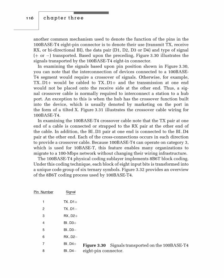
116 c h a p t e r t h r e e
another common mechanism used to denote the function of the pins in the100BASE-T4 eight-pin connector is to denote their use (transmit TX, receiveRX, or bi-directional BI), the data pair (D1, D2, D3 or D4) and type of signal(+ or −) transported. Based upon the preceding, Figure 3.30 illustrates thesignals transported by the 100BASE-T4 eight-in connector.
In examining the signals based upon pin position shown in Figure 3.30,you can note that the interconnection of devices connected to a 100BASE-T4 segment would require a crossover of signals. Otherwise, for example,TX−D1+ would be cabled to TX−D1+ and the transmission at one endwould not be placed onto the receive side at the other end. Thus, a sig-nal crossover cable is normally required to interconnect a station to a hubport. An exception to this is when the hub has the crossover function builtinto the device, which is usually denoted by marketing on the port inthe form of a tilted X. Figure 3.31 illustrates the crossover cable wiring for100BASE-T4.
In examining the 100BASE-T4 crossover cable note that the TX pair at oneend of a cable is connected or strapped to the RX pair at the other end ofthe cable. In addition, the BI−D3 pair at one end is connected to the BI−D4pair at the other end. Each of the cross-connections occurs in each directionto provide a crossover cable. Because 100BASE-T4 can operate on category 3,which is used for 10BASE-T, this feature enables many organizations tomigrate to a 100-Mbps network without changing their wiring infrastructure.
The 100BASE-T4 physical coding sublayer implements 8B6T block coding.Under this coding technique, each block of eight input bits is transformed intoa unique code group of six ternary symbols. Figure 3.32 provides an overviewof the 8B6T coding process used by 100BASE-T4.
Figure 3.30 Signals transported on the 100BASE-T4eight-pin connector.

ethernet networks 117
Pinnumber Signal
1 TX_D1+2 TX_D1−3 RX_D2+6 RX_D2−4 BI_D3+5 BI_D3−7 BI_D4+8
Pinnumber
12364578BI_D4−
Signal
TX_D1+TX_D1−RX_D2+RX_D2−BI_D3+BI_D3−BI_D4+BI_D4−
Figure 3.31 100BASE-T4 crossover wiring.
Input data stream
Output code groups
1 2 3 4 5 6 7 8
1 2 3 4 5 6 1 2 3 4 5 6 1 2 3 4 5 6 • • •
1 2 3 4 5 6 7 8 1 2 3 4 5 6 7 8
Figure 3.32 8B6T coding process.
The output code groups resulting from 8B6T coding flow out to three parallelchannels that are placed on three twisted pairs. Thus, the effective data rateon each pair is 100 Mbps/3, or 33.33 Mbps. Because 6 bits are representedby 8 bit positions, the signaling rate or baud rate on each cable pair becomes33 Mbps × 6/8, or 25 MHz, which is the clock rate used at the MII sublayer.
100BASE-TX
100BASE-TX represents the use of two pairs of category 5 UTP cabling withRJ-45 connectors or two pairs of category 5 STP cable terminated with thecommon DB-9 communications connector used on the serial port of manynotebook computers.
Because UTP is relatively inexpensive and two pair is less costly thanfour pair, 100BASE-TX represents a more popular version of Fast Ethernetthan 100BASE-T4. The UTP wire actually used must meet the EIA/TIA 568category 5 wire specifications. A 100BASE-TX network requires a hub, andthe maximum cable run is 100 meters from hub port to node, with a maximumnetwork diameter of 200 meters.
Figure 3.33 illustrates the cabling of two pairs of UTP wires between a huband node to support 100BASE-TX transmission. One pair of wires is used for

118 c h a p t e r t h r e e
Hub port Network node
Pair 1
Pair 2
Pair 1
Pair 2Figure 3.33 100BASE-TX cabling.
transmission, while the second pair is used for collision detection and recep-tion of data. The use of a 125-MHz frequency requires the use of a data gradecable. Thus, 100BASE-TX is based upon the use of category 5 UTP and STP.
Similar to 100BASE-T4, 100BASE-TX uses an eight-pin connector whenUTP is employed. Figure 3.34 illustrates the use of each of the eight pins. Notethat the transmit and receive data signals on each pair transport positive (+)and negative (−) signals. Also note that 100BASE-TX transmission via UTPuses the same pin assignments as 10BASE-T hardware, enabling the samecategory 5 wiring system to be used without any change to wiring beingrequired. This provides network administrators with a considerable degreeof flexibility for upgrading from 10BASE-T to 100BASE-TX once category 5cabling is installed.
Similar to our discussion concerning 100BASE-TX, when two stations areconnected over a segment the transmit data pins on one side must be wiredto the receive data pins on the distant end and vice versa. Thus, unless a hubhas a port with a built-in crossover you need to use a 100BASE-TX crossovercable to connect a station to a hub. Figure 3.35 illustrates the connection ofpins required for a 100BASE-TX crossover cable.
Similar to 10BASE-T, 100BASE-TX has separate transmit and receive signalpaths. Because these paths can be simultaneously active 100BASE-TX cansupport full duplex transmission. If STP cabling is used the connector will be
Figure 3.34 100BASE-TX eight pin connector usedwith UTP.

ethernet networks 119
Pinnumber Signal
1 TD1+2 TD1−3 RD2+6 RD2−
Pinnumber
1236
Signal
TD1+TD1−RD2+RD2−
Figure 3.35 100BASE-TX crossover cable.
Figure 3.36 100BASE-TX nine-pin D-connector forSTP use.
a nine-pin ‘‘D-type’’ connector similar to the ones used on the serial port ofnotebook computers. Figure 3.36 illustrates the use of the pins on the 9-pinD-connector.
Although the 100BASE-TX physical layer structure resembles the 100BASE-T4 layer, there are significant differences between the two to accommodatethe differences in media used. At the physical coding sublayer, the 100-Mbpsstart-stop bit stream from the MII is first converted to a full-duplex 125-Mbpsbit stream. This conversion is accomplished by the use of the FDDI PMDas the 100BASE-TX PMD. Next, the data stream is encoded using a 4B5Bcoding scheme. The 100BASE-TX PMD decodes symbols from the 125-Mbpscontinuous bit stream and converts the stream to 100-Mbps start-stop data bitswhen the data flow is reversed.
4B5B Coding
The use of a 4B5B coding scheme enables data and control information tobe carried in each symbol represented by a 5-bit code group. In addition,

120 c h a p t e r t h r e e
an inter-Stream fill code (IDLE) is defined, as well as a symbol used toforce signaling errors. Because 4 data bits are mapped into a 5-bit code, only16 symbols are required to represent data. The remaining symbols not usedfor control or to denote an IDLE condition are not used by 100BASE-TX andare considered as invalid.
Table 3.6 lists the 4B5B 100BASE-TX code groups. Because an explanationof the use of the control codes and IDLE code requires an examination of theMAC frame, we will defer our discussion of those symbols until Chapter 4, asframe formats are discussed in that chapter.
100BASE-FX
100BASE-FX represents the third 100BASE-T wiring scheme, defining FastEthernet transmission over fiber-optic media. 100BASE-FX requires the useof two-strand 62.5/125-micron multimode fiber media and supports the 4B5Bcoding scheme, identical to the one used by 100BASE-TX.
100BASE-FX provides an extended network diameter of up to 400 meters.However, in a mixed 100BASE-T4 and 100BASE-FX environment, thecollision domain should not exceed 231 meters, consisting of 100 metersfor 100BASE-T4 and 131 meters for 100BASE-FX. Concerning connectors,100BASE-FX supports both ST and SC fiber connectors, which were originallydefined for FDDI.
Network Construction and Use
Similar to 10-Mbps Ethernet networks, you can use adapter cards, cable,and hubs to construct a variety of Fast Ethernet networks to satisfy differentorganizational network requirements. However, when doing so, it is importantto understand the role of repeaters in a Fast Ethernet environment, as thestandard defines two types, each having a different effect upon networkconstruction.
Repeater Rules
When we examined Ethernet we discussed the 5-4-3 rule, which applied to acommon type of repeater. When we discuss Fast Ethernet we must considertwo types of repeaters, referred to as Class I and Class II repeaters.

ethernet networks 121
TABLE 3.6 4B/5B Code Groups
PCS Code Group MII (TXD/RXD)
4 3 2 1 0 Name 3 2 1 0 Interpretation
DATA
1 1 1 1 0 0 0 0 0 0 Data 0
0 1 0 0 1 1 0 0 0 1 Data 1
1 0 1 0 0 2 0 0 1 0 Data 2
1 0 1 0 1 3 0 0 1 1 Data 3
0 1 0 1 0 4 0 1 0 0 Data 4
0 1 0 1 1 5 0 1 0 1 Data 5
0 1 1 1 0 6 0 1 1 0 Data 6
0 1 1 1 1 7 0 1 1 1 Data 7
1 0 0 1 0 8 1 0 0 0 Data 8
1 0 0 1 1 9 1 0 0 1 Data 9
1 0 1 1 0 A 1 0 1 0 Data A
1 0 1 1 1 B 1 0 1 1 Data B
1 1 0 1 0 C 1 1 0 0 Data C
1 1 0 1 1 D 1 1 0 1 Data D
1 1 1 0 0 E 1 1 1 0 Data E
1 1 1 0 1 F 1 1 1 1 Data F
IDLE
1 1 1 1 1 I IDLE:Used as inter-Stream fill code
CONTROL
1 1 0 0 0 J Start-of-stream delimiter, part 1 of 2;always used in pairs with K.
1 0 0 0 1 K Start-of-stream delimiter, part 2 of 2; alwaysused in pairs with J.
(continued overleaf )

122 c h a p t e r t h r e e
TABLE 3.6 (Continued)
PCS Code Group MII (TXD/RXD)
4 3 2 1 0 Name 3 2 1 0 Interpretation
0 1 1 0 1 T End-of-stream delimiter, part 1 of 2;always used in pairs with R.
0 0 1 1 1 R End-of-stream delimiter, part 2 of 2;always used in pairs with T.
INVALID
0 0 1 0 0 H Transmit error; used to force signaling errors.
0 0 0 0 0 V Invalid code
0 0 0 0 1 V Invalid code
0 0 0 1 0 V Invalid code
0 0 0 1 1 V Invalid code
0 0 1 0 1 V Invalid code
0 0 1 1 0 V Invalid code
0 1 0 0 0 V Invalid code
0 1 1 0 0 V Invalid code
1 0 0 0 0 V Invalid code
1 1 0 0 1 V Invalid code
A Class I repeater has a greater budget for timing delay, enabling it to be usedto support dissimilar physical media segments that use dissimilar signalingsuch as 100BASE-T4 and 100BASE-TX. This support is possible because thegreater timing budget of the Class I repeater enables it to translate the linesignal received on one port to a different type of signal for transmissiononto other ports. Only one Class I repeater can be installed in a segment. Incomparison, a Class II repeater has a lower budget for timing delay, resultingin it being faster than a Class I repeater. This enables up to two Class IIrepeaters to be used in a segment; however, in doing so the interrepeater cablelength is limited to 5 meters when data terminal equipment are 100 metersfrom repeaters. Because a Class II repeater immediately repeats an incomingsignal onto all other ports other than the port data was received on withouta translation process being possible, it can only be used to interconnect
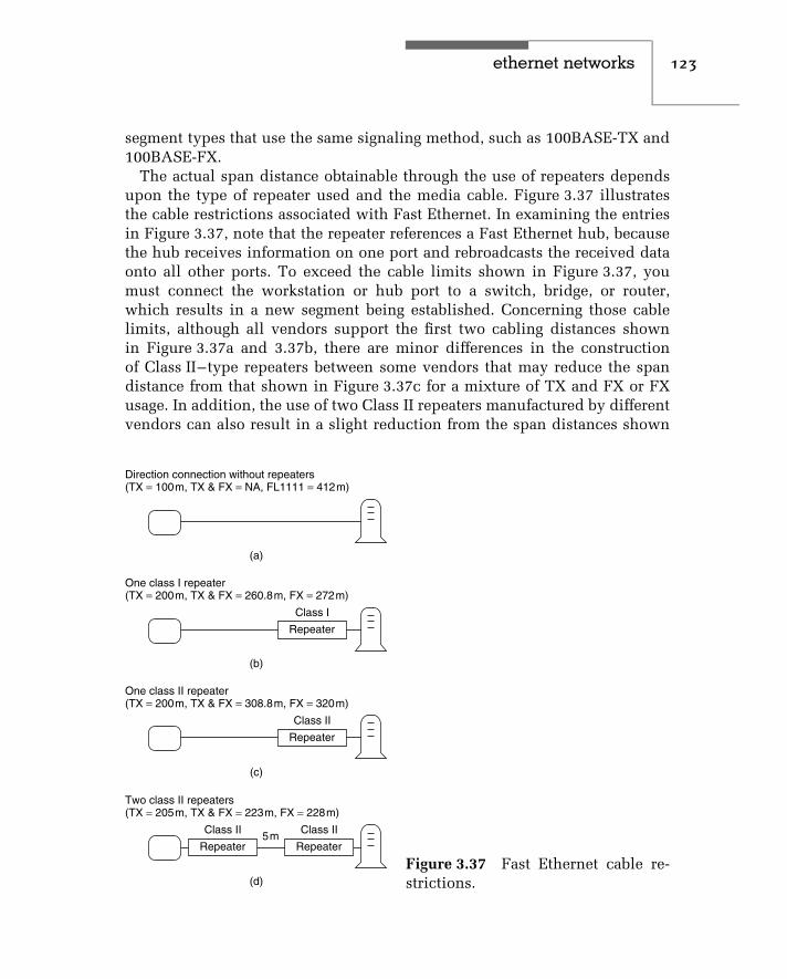
ethernet networks 123
segment types that use the same signaling method, such as 100BASE-TX and100BASE-FX.
The actual span distance obtainable through the use of repeaters dependsupon the type of repeater used and the media cable. Figure 3.37 illustratesthe cable restrictions associated with Fast Ethernet. In examining the entriesin Figure 3.37, note that the repeater references a Fast Ethernet hub, becausethe hub receives information on one port and rebroadcasts the received dataonto all other ports. To exceed the cable limits shown in Figure 3.37, youmust connect the workstation or hub port to a switch, bridge, or router,which results in a new segment being established. Concerning those cablelimits, although all vendors support the first two cabling distances shownin Figure 3.37a and 3.37b, there are minor differences in the constructionof Class II–type repeaters between some vendors that may reduce the spandistance from that shown in Figure 3.37c for a mixture of TX and FX or FXusage. In addition, the use of two Class II repeaters manufactured by differentvendors can also result in a slight reduction from the span distances shown
(a)
(b)
(c)
(d)
Direction connection without repeaters(TX = 100m, TX & FX = NA, FL1111 = 412m)
One class I repeater(TX = 200m, TX & FX = 260.8m, FX = 272m)
Repeater
Class I
One class II repeater(TX = 200m, TX & FX = 308.8m, FX = 320m)
Repeater
Class II
Two class II repeaters(TX = 205m, TX & FX = 223m, FX = 228m)
Repeater
Class II
Repeater
Class II5m
Figure 3.37 Fast Ethernet cable re-strictions.

124 c h a p t e r t h r e e
in Figure 3.37d for a mixture of TX and FX and FX repeater use. Thus, itis highly recommended to check vendor specification sheets concerning thenetwork guidelines associated with a particular type of repeater.
Because 100BASE-T4 and 100BASE-TX preserve the 10BASE-T MAC layer,both standards are capable of interoperability with existing 10BASE-T net-works as well as with other low-speed Ethernet technology. Through the useof NWay autosensing logic, Fast Ethernet adapters, hub, and switch ports candetermine if attached equipment can transmit at 10 or 100 Mbps and adjust tothe operating rate of the distant device.
Autonegotiation
Auto-negotiation represents an optical feature which was added to the metal-lic copper versions of Fast Ethernet and which is now incorporated into mosttypes of such hardware. The basis for auto-negotiation can be traced to atechnology referred to as NWay. NWay represents a cable and transmissionautosensing scheme proposed by National Semiconductor to the IEEE 802.3standards group in May 1994. NWay incorporated an autosensing scheme topermit Ethernet circuits to detect both the cable type and speed of incomingEthernet data, as well as enabled Ethernet repeaters to configure themselvesfor correct network operations. Because NWay can detect 10-Mbps versus100-Mbps operations, as well as half- and full-duplex transmission, it formedthe basis for autonegotiation which permits Ethernet circuits to be devel-oped to automatically adjust to the operating rate and cabling scheme used.This in turn simplifies the efforts of network managers and administrators,because products incorporating autonegotiation are self-configurable and donot require the setting of DIP switches or software parameters.
Auto-negotiation relies upon a modification to the link integrity test usedby 10BASE-T, replacing the link test pulse with a burst of pulses referred to asfast link pulses (FLPs). Each FLP consists of a series of clock and data pulses,with the data pulses used to form a 16-bit link code work (LCW).
Figure 3.38 illustrates the composition of the LCW. Note that the five-bit selector field makes it possible for auto-negotiation to be supported byToken-Ring (802.5) networks. In comparison, the eight-bit Technology Abilityfield defines the technology supported. The Pause bit in the TechnologyAbility Field was added to support full-duplex operations and when setindicates if the device supports a Pause Mechanism. If so, the other devicecan transmit a Pause Frame that will inform the receiving device to delayits transmission. This form of flow control becomes necessary when a 100-Mbps device communicates with a lower-speed device and the latter could beoverwhelmed with data. Thus, the 100-Mbps device will need to inform other

ethernet networks 125
00001 = 802.3 A0 = 10BASE-T
Selector field
S0 S1 S2 S3 S4 A0 A1 A2 A3 A4 A5 A6 A7 RF ACK NP
Technology ability field
00010 = 802.5 A1 = 10BASE-T Full DuplexA2 = 100BASE-TXA3 = 100BASE-TX Full DuplexA4 = 100BASE-T4A5 = PauseRF = Remote FaultACK = AcknowledgeNP = Next Page
Figure 3.38 The format of the link code word.
devices to delay their transmission. In Chapter 4 when we examine the formatof different types of Ethernet frames we will also examine the Pause Frame.
Returning our attention to Figure 3.38, the Remote Fault indicates thepresence of a fault detected by the station at the opposite end of the link.When this bit (RF) is set, it indicates that the distant device is in its link-failedstate, a condition typically resulting from a malfunctioning receiver or brokencable. The next to last bit in the LCW is the ACK bit. This bit is used toindicate the successful receipt of the previously transmitted LCW. The lastbit is the next page bit. When set this bit indicates that additional proprietaryinformation follows.
The link code word is transmitted on power-up or when requested by eitherdevice on a link. The composition of fast link pulses appears similar to alink integrity test, enabling a 10BASE-T device to respond. However, if theremote station is a 100 Mbps device, its receive clock will be sufficient tointerpret the individual pulses that form the LCM, enabling the determinationof operations at 10 Mbps or 100 Mbps.
When two devices that support auto-negotiation have multiple capabilities,they need to determine their highest performance mode of operation. Indoing so, they consult a priority table. Table 3.7 lists the priorities for auto-negotiation from highest to lowest. Note that full duplex has a higher prioritythan half duplex since the former has a higher throughput capability thanthe latter.
Autonegotiation can operate on an individual end basis or withautonegotiation-compliant devices at both ends of a twisted-pair link. Anexample of this autonegotiation capability is shown in Figure 3.39 in which

126 c h a p t e r t h r e e
TABLE 3.7 Auto-negotiation Priority Table
Priority Technology Cable
1 100BASE-TX Full Duplex 2 pair, category 5
2 100BASE-T4 4 pair, category 3
3 100BASE-TX 2 pair, category 5
4 10BASE-T Full Duplex 2 pair, category 3
5 10BASE-T 2 pair, category 3
10BASE-T/100BASE-TXswitching hub with
autonegotiation
Autonegotiation10BASE-T/
100BASE-TX 10BASE-T
StationA
StationB
Figure 3.39 Autonegotiation. Through the use of autonegotiation, the10BASE-T/100BASE-TX switching hub will operate at 100 Mbps withstation A and at 10 Mbps with station B.
station A has a NIC with autonegotiation capability that is cabled to a 10BASE-T/100BASE-TX switching hub whose port has an autonegotiation capability,while station B has a conventional 10BASE-T NIC. In this example, thehub port connected to station A would operate at 100 Mbps as 100BASE-TXdevices. In comparison, the hub port connection to station B would recognizethe 10BASE-T signals from station B and switch to 10BASE-T operations.
Operation
There are several network configurations you can consider for Fast Ethernetoperations. First, you can construct a 100BASE-TX network similar to a10BASE-T network, using an appropriate hub and workstations that supportthe specific network type. This type of network, commonly referred to as ashared-media hub-based network, should be considered when most, if not all,

ethernet networks 127
network users access one or a limited number of servers to perform graphic-intensive or similar bandwidth-intensive operations, and the sharing of the100-Mbps transmission capability provides an acceptable average bandwidthper network node. Figure 3.40a illustrates a Fast Ethernet shared-media hubnetwork configuration.
In examining Figure 3.40a note that the single CSMA/CD network representsa collision domain. Here the term collision domain references a networkstructure in which a collision will occur if two computers attached to thenetwork transmit at the same time. If one hub is wired to another or twosegments are joined together by a repeater the resulting network structurecontinues to function as a single collision domain.
Another common use for Fast Ethernet is in its incorporation into oneor more ports in an Ethernet switch. An Ethernet switch can be viewed as
All connections operate at 100 Mbps.
Ser-ver
Image/videoserver
Applica-tion
server
Legend:
(a) Shared-media hub.
Some connections operate at 100 Mbps and some at 10 Mbps.
(b) 10/100 Mbps ethernet switch.
= Workstation
= Fat pipe
Figure 3.40 Fast Ethernet network applications.
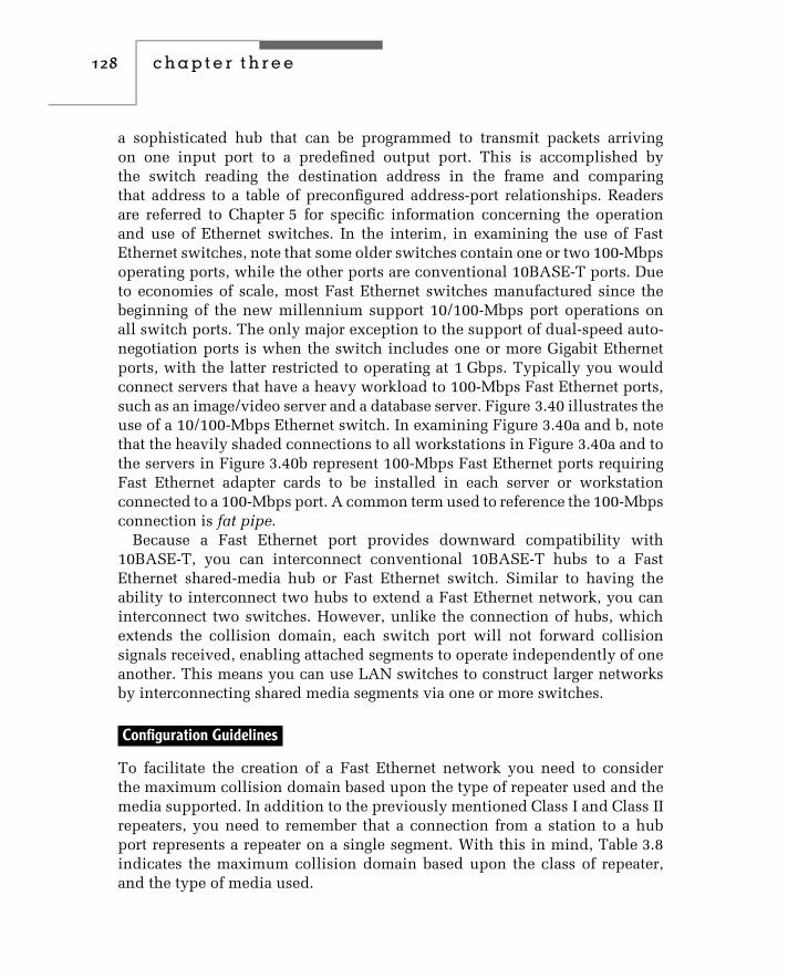
128 c h a p t e r t h r e e
a sophisticated hub that can be programmed to transmit packets arrivingon one input port to a predefined output port. This is accomplished bythe switch reading the destination address in the frame and comparingthat address to a table of preconfigured address-port relationships. Readersare referred to Chapter 5 for specific information concerning the operationand use of Ethernet switches. In the interim, in examining the use of FastEthernet switches, note that some older switches contain one or two 100-Mbpsoperating ports, while the other ports are conventional 10BASE-T ports. Dueto economies of scale, most Fast Ethernet switches manufactured since thebeginning of the new millennium support 10/100-Mbps port operations onall switch ports. The only major exception to the support of dual-speed auto-negotiation ports is when the switch includes one or more Gigabit Ethernetports, with the latter restricted to operating at 1 Gbps. Typically you wouldconnect servers that have a heavy workload to 100-Mbps Fast Ethernet ports,such as an image/video server and a database server. Figure 3.40 illustrates theuse of a 10/100-Mbps Ethernet switch. In examining Figure 3.40a and b, notethat the heavily shaded connections to all workstations in Figure 3.40a and tothe servers in Figure 3.40b represent 100-Mbps Fast Ethernet ports requiringFast Ethernet adapter cards to be installed in each server or workstationconnected to a 100-Mbps port. A common term used to reference the 100-Mbpsconnection is fat pipe.
Because a Fast Ethernet port provides downward compatibility with10BASE-T, you can interconnect conventional 10BASE-T hubs to a FastEthernet shared-media hub or Fast Ethernet switch. Similar to having theability to interconnect two hubs to extend a Fast Ethernet network, you caninterconnect two switches. However, unlike the connection of hubs, whichextends the collision domain, each switch port will not forward collisionsignals received, enabling attached segments to operate independently of oneanother. This means you can use LAN switches to construct larger networksby interconnecting shared media segments via one or more switches.
Configuration Guidelines
To facilitate the creation of a Fast Ethernet network you need to considerthe maximum collision domain based upon the type of repeater used and themedia supported. In addition to the previously mentioned Class I and Class IIrepeaters, you need to remember that a connection from a station to a hubport represents a repeater on a single segment. With this in mind, Table 3.8indicates the maximum collision domain based upon the class of repeater,and the type of media used.

ethernet networks 129
TABLE 3.8 Fast Ethernet Maximum Collision Domain (Meters)
Type of Media
Type of Repeater Copper Fiber
Copper andFiber
(T4 and FX)
Copper andFiber
(TX and FX)
Single Segment 100 412 N/A N/A
One Class I 200 272 231∗ 260∗
One Class II 200 320 N/A† 308∗
Two Class II 205 228 N/A† 216‡
Notes:∗Assumes 100 meters of copper and one fiber link.†Not applicable as T4 and FX cannot be interconnected using a Class II repeater.‡Assumes 105 meters of copper and one fiber link.
In examining the entries in Table 3.8 note that the first entry representsa station-to-station connection with no intermediate repeaters. As indicated,the maximum amount of cabling is 100 meters when copper is used and412 meters when fiber-optic cable is employed. Figure 3.41 illustrates anexample of the structure of a Fast Ethernet network consisting of three sharedmedia hubs and a switch.
An examination of Figure 3.41 should be performed in conjunction withthe entries in Table 3.8 for the figure to be meaningful. For example, fromTable 3.8, the maximum collision domain for a class II repeater is 205 meters.If you focus your attention upon collision domain 1 in Figure 3.41, youwill note that the inter-repeater segment is shown as 5 meters to keep themaximum collision diameter equal or below 205 meters. You can increase theinter-repeater segment length; however, you would then need to reduce theother segments to ensure that the maximum collision diameter in the domaindoes not exceed 205 meters.
Computer Bus Considerations
In addition to having to consider the type or types of NIC connectors, itis also extremely important to consider the bus they are designed to workwith along with driver support for different operating systems. Some NICsare limited to one type of connector, requiring the purchase of a separateconverter if you decide to use a different media other than the media the NICwas manufactured to directly support.
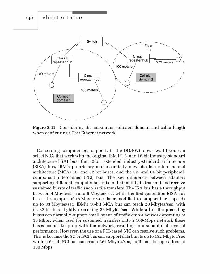
130 c h a p t e r t h r e e
Class IIrepeater hub
100 meters
100 meters
100 meters272 meters
Fiberlink
Class Irepeater hub
Switch
Class IIrepeater hub
Collisiondomain 1
Collisiondomain 2
Figure 3.41 Considering the maximum collision domain and cable lengthwhen configuring a Fast Ethernet network.
Concerning computer bus support, in the DOS/Windows world you canselect NICs that work with the original IBM PC 8- and 16-bit industry-standardarchitecture (ISA) bus, the 32-bit extended industry-standard architecture(EISA) bus, IBM’s proprietary and essentially now obsolete microchannelarchitecture (MCA) 16- and 32-bit buses, and the 32- and 64-bit peripheral-component interconnect (PCI) bus. The key difference between adapterssupporting different computer buses is in their ability to transmit and receivesustained bursts of traffic such as file transfers. The ISA bus has a throughputbetween 4 Mbytes/sec and 5 Mbytes/sec, while the first-generation EISA bushas a throughput of 16 Mbytes/sec, later modified to support burst speedsup to 33 Mbytes/sec. IBM’s 16-bit MCA bus can reach 20 Mbytes/sec, withits 32-bit bus slightly exceeding 36 Mbytes/sec. While all of the precedingbuses can normally support small bursts of traffic onto a network operating at10 Mbps, when used for sustained transfers onto a 100-Mbps network thosebuses cannot keep up with the network, resulting in a suboptimal level ofperformance. However, the use of a PCI-based NIC can resolve such problems.This is because the 32-bit PCI bus can support data bursts up to 132 Mbytes/secwhile a 64-bit PCI bus can reach 264 Mbytes/sec, sufficient for operations at100 Mbps.

ethernet networks 131
Figure 3.42 The 3Com Corporation Fast Etherlink TX NIC supports the useof the ISA bus. (Photograph courtesy of 3Com Corporation.)
Figures 3.42 through 3.44 illustrate three 3Com Corporation Fast EthernetNICs manufactured to support different computer buses. Figure 3.42 showsthe 3Com 3C515-TX NIC, which supports the ISA bus. Figure 3.43 shows the3Com Corporation’s Fast Etherlink PT adapter, which supports the EISA bus.The third 3Com NIC shown in Figure 3.44 is the Fast Etherlink XL, designedto support the PCI bus.
A third NIC-related item that warrants careful consideration when selectingan appropriate NIC is the drivers available for use with the adapter. Today,in addition to different versions of NetWare and Windows, there are otheroperating systems ranging from LINUX to different versions of UNIX you mayneed to support. Although support for many NICs and protocols is built intomany operating systems, such support is not all-inclusive. This means youmay have to obtain one or more files from the NIC manufacturer to be ableto use the NIC with a particular operating system. Figure 3.45 illustrates howunder Windows NT Version 4.0 you would select the ‘‘Have Disk’’ option ifyour NIC wasn’t directly supported, resulting in the display of the ‘‘InsertDisk’’ dialog box to enable NT to recognize your adapter.
One of the more interesting aspects concerning the use of NIC drivers,obtained from firsthand experience, is to ensure you have the appropriate

132 c h a p t e r t h r e e
Figure 3.43 The 3Com Corporation Fast Etherlink PT NIC supports the useof the EISA bus. (Photograph courtesy of 3Com Corporation.)
Figure 3.44 The 3Com Corporation Fast Etherlink XL NIC supports the useof the PCI bus. (Photograph courtesy of 3Com Corporation.)

ethernet networks 133
Figure 3.45 When using Windows NT you can specify a ‘‘Have Disk’’ optionto use a NIC adapter not directly supported by that operating system.
driver. On occasion, it was found that the diskette packaged with the NICmanual and shipped with a newly purchased computer did not contain theappropriate driver for the computer. Although the operating system woulduse the driver, the computer would freeze about once a month, a situationcorrected when it was determined that the computer manufacturer had a Website with updated drivers for the NIC shipped with their computer.
100VG-AnyLAN
100VG-AnyLAN was originally proposed by AT&T Microelectronics andHewlett-Packard Company as a mechanism to support evolving LAN-basedmultimedia applications. To accomplish this, the proposal, which became theIEEE 802.12 standard, replaced the CSMA/CD access protocol by a demand-priority scheme. This scheme enables the transmission of time-sensitivevideo and voice associated with multimedia applications in preference toconventional data that is relatively time-insensitive. In addition, the useof a demand-priority scheme extends 100VG-AnyLAN beyond Ethernet,
134 c h a p t e r t h r e e
enabling this network to support Token-Ring, FDDI, and other types of localarea networks.
Although 100VG-AnyLAN included many interesting technical charac-teristics, it never achieved widespread adoption. The significant commercialsuccess of 100BASE-T, as well as the rapid reduction in the cost ofGigabit Ethernet hardware, more than likely affected its adoption. In late2000, Hewlett-Packard, which was the major proponent of 100VG-AnyLAN,announced plans to discontinue the sale and future development of interfacecards, software license and documentation for its e3000 business servers.
Architecture
While recognizing that the market for VG-AnyLAN is minimal, in order toprovide readers with information about different types of Ethernet networks,in concluding this section we will briefly examine the architecture and basicoperation associated with the technology.
100VG-AnyLAN was designed as a hub-centric network architecture. Acentral hub, known as a level-1 or root hub, functions as an inverted treebase in establishing a 100VG-AnyLAN network. From this hub other hubsand/or nodes form a star topology, fanning out underneath the root hub, asillustrated in Figure 3.46. All hubs located in the same network segment mustbe configured to support the same frame format — IEEE 802.3 Ethernet or IEEE802.5 Token-Ring. Through the attachment of a bridge or router to a hubport you can extend the 100VG-AnyLAN network to interconnect with otherEthernet or Token-Ring networks, FDDI- and ATM-based networks, or a widearea network transmission facility.
Each hub in a 100VG-AnyLAN network has one up-link port, labeledup in Figure 3.46; and n down-link ports, labeled 1 through N . The up-link port on each hub is reserved for connecting lower-level hubs to anupper-level hub, while the down-link ports are used to connect an upper-level hub to workstations, bridges, routers, and other network devices toinclude lower-level hubs. Up to three levels of cascading can be used on a100VG-AnyLAN network.
Hub Operation
Each hub port can be configured to operate in one of two modes — normalor monitor. Ports configured to operate in their normal mode are forwardedonly those packets specifically addressed to the attached node. In comparison,ports configured to operate in the monitor mode are forwarded every packetreceived by the hub.

ethernet networks 135
Up
1
Level-1 Root hub
2
WS1-1
3 4 • • •
• • •
N
WS1-2
WS1-4
WS1-N
Up
1
Level-2 hub
Legend: WS 1-p = workstation hub level-port
2
WS2-1
3 N
WS2-2
WS2-N
Figure 3.46 100VG-AnyLANtopology.
Devices connected to nodes gain access to a 100VG-AnyLAN networkthrough the use of a centrally controlled access method, referred to as demand-priority. Under the demand-priority access method a node issues a request,referred to as a demand, to the hub it is connected to, to transmit a packetonto the 100VG-AnyLAN network. Each request includes a priority labelassigned by the upper-layer application. The priority label is either normal,for normal data packets, or high, for packets carrying time-critical multimediainformation. As you might expect, high-priority requests are granted access tothe network before normal-priority requests are granted.
The level 1 or root hub continuously scans its ports using a round-robinsequence for requests. Lower-level hubs connected as nodes also perform around-robin scanning process and forward node requests to the root hub.The root hub determines which nodes are requesting permission to transmita packet as well as the priority level associated with the packet. Each hubmaintains a separate list for both normal- and high-priority requests.
Normal-priority requests are serviced in their port order until a higher-priority request is received. Upon receipt of a higher-priority request thehub will complete any packet transmission in progress and then service thehigh-priority packet before returning to service the normal-priority list.
To prevent a long sequence of high-priority requests from abnormallydelaying low-priority requests from being serviced, the hub also monitors

136 c h a p t e r t h r e e
node request-to-send response times. If the delay exceeds a predefinedtime, the hub automatically raises the normal-priority level to a high-priority level.
Round-Robin Scanning
Figure 3.47 illustrates an example of the 100VG-AnyLAN hub round-robinscanning process. Assume all ports initially have normal-priority requestspending. Then, the round-robin sequence at the root or level 1 hub resultsin the packet service order commencing at the level 1 hub’s first port (1-1).Next, the level 1 hub’s second port is serviced (1-2). When the third portis examined, it inserts the round-robin sequence generated by the level 2hub. That is, it inserts the packet order sequence 2-1, 2-2, 2-3, . . ., 2-N. Thissequence is then followed by adding the remaining level 1 hub ports. Thus, theinserted packet order sequence is followed by the sequence 1-4, . . ., 1-N. Nowlet’s assume at time t = 0 nodes 2-1 and 1-4 generate high-priority requests.Then, the packet service order at the level 1 hub would be revised, becoming2-1, 1-4, 1-1, 1-2, 2-2, . . ., 2-N, 1-5, . . ., 1-N.
Up
• • •
• • •
1
Level-1 Root hub
2
WS1-1
3 4 N
WS1-2
WS1-4
WS1-N
Up
1
Level-2 hub
If all ports have normal-priority requests pending, then:Level-1 scan 1-1, 1-2, 1-3, 1-4, ..., 1-N
Level-2 scan 2-1, 2-2, 2-3, ..., 2-N
Level-1 resulting packet order sequence 1-1, 1-2, 2-1, 2-2, 2-3, ..., 2-N, 1-4, ..., 1-N
2
WS2-1
3 N
WS2-2
WS2-N
Figure 3.47 100VG-AnyLAN hubround-robin scanning.

ethernet networks 137
Cabling Requirements
100VG-AnyLAN products provide a 100-Mbps data rate using 4-pair cate-gory 3, 4, or 5 unshielded twisted-pair cable. 100VG-AnyLAN also supports2-pair UTP, 2-pair STP, and fiber-optic cabling. The cabling medium requiredfor 4-pair 100VG-AnyLAN is 4-pair UTP that meets the specifications of theEIA/TIA-568 standard for 100-ohm category 3, 4, or 5 cable. Such cable con-nects to RJ-45 wall jacks and can go through punch-down blocks or patchpanels in a wiring closet.
Figure 3.48 indicates the RJ-45 modular plug pin assignments for 4-UTP100VG-AnyLAN. In addition, this illustration indicates for comparison pur-poses the pairs used by 10BASE-T and Token-Ring cable.
Comparing Technologies
Both 100BASE-T and 100VG-AnyLAN provide users with a tenfold increasein network operating rates with respect to 10BASE-T. However, the 100-Mbps
1
100VG-AnyLAN (4-UTP)
2
Pair 2 Pair 1
Pair 3
Pair 4
3 4 5 6 7 8
1
10BASE-T
2
Pair 1
Pair 2
3 4 5 6 7 8
1
Token-ring
2
Pair 1
Pair 2
3 4 5 6 7 8
Figure 3.48 RJ-45 modular plugpin assignments.
138 c h a p t e r t h r e e
operating rate represents one of the few common operating characteristicsbetween the two technologies.
100BASE-T was designed as a mechanism to provide a growth path from100BASE-T while enabling organizations to retain the invested base of10BASE-T adapter cards and cabling for workstations that do not requirea 100-Mbps operational capability. In doing so, no provision was made toprioritize traffic. Thus, while a lightly or medium loaded 100BASE-T net-work can transport multimedia data, this may not be true as the networkload increases.
The replacement of the CSMA/CD access protocol by a demand-priorityprotocol results in 100VG-AnyLAN being more suitable for multimediaapplications. Unfortunately, there is a cost associated with the additionaltechnology incorporated into 100VG-AnyLAN, which resulted in networkadapters initially costing 50 percent more than 100BASE-T adapters andprecluded its widespread adoption. Table 3.9 provides a comparison of theoperating characteristics of 100BASE-T and 100VG-AnyLAN.
A comparison of 100VG-AnyLAN to 100BASE-T is probably similar to acomparison of Beta to VHS. While Beta was a superior technology, the VHSextended record and playback time better satisfied consumer requirements.If we turn our focus back to LANs, 100BASE-T better interoperates with10BASE-T through an auto-negotiation capability. This makes it easier toconstruct interoperable networks. Based upon the preceding, 100BASE-Tproducts dominate the high-speed Ethernet marketplace.
3.5 Gigabit Ethernet
Gigabit Ethernet represents an extension to the 10-Mbps and 100-MbpsIEEE 802.3 Ethernet standards. Providing a data transmission capability of1000 Mbps, Gigabit Ethernet supports the CMSA/CD access protocol, whichmakes various types of Ethernet networks scalable from 10 Mbps to 1 Gbps,with the pending standardization of 10-Gigabit Ethernet providing additionalscalability to 10 Gbps.
Components
Similar to 10BASE-T and Fast Ethernet, Gigabit Ethernet can be used asa shared network through the attachment of network devices to a 1-Gbpsrepeater hub providing shared use of the 1-Gbps operating rate or as a switch,

ethernet networks 139
TABLE 3.9 Operating Characteristics Comparison
Data rate 100BASE-T 100VG-AnyLAN
100 Mbps 100 Mbps
Access protocol CSMA/CD Demand-priority
Frame support 802.3 Ethernet 802.3 Ethernet
802.5 Token-Ring
Physical topology Star Star
Cable support2-pair Category 5 UTP 100BASE-TX Not planned4-pair Category 3, 4, or 5 UTP 100BASE-T4 Yes2-pair STP 100BASE-TX YesFiber 100BASE-FX Yes
Maximum UTP drive distance 100 meters onCategory 5 UTP
100 meters Category3, 4, UTP
Maximum repeaters allowed 2 4
Maximum UTP network diameter 200 meters 4,000 meters
Other cabling 2-pair Type 1 STP;optical fiber; 4-pairCategory 3, 4, 5 UTP
2-pair Type 1 STP;optical fiber; 2-pairCategory 5 UTP
Full duplex support Yes Yes
the latter providing 1-Gbps ports to accommodate high-speed access to serverswhile lower operating rate ports provide access to 10-Mbps and 100-Mbpsworkstations and hubs. Although few organizations can be expected to requirethe use of a 1-Gbps shared media network as illustrated in Figure 3.49a,the use of Gigabit switches can be expected to play an important role inproviding a high-speed backbone linking 100-Mbps network users to largedatabases, mainframes, and other types of resources that can tax lower-speednetworks. In addition to hubs and switches, Gigabit Ethernet operationsrequire workstations, bridges, and routers to use a network interface card toconnect to a 1-Gbps network. Gigabit Ethernet NICs introduced when this bookwas written were designed for PCI bus operations and use an SC fiber connectorto support 62.5/125 and 50/125 micron fiber. Such adapters provide 1 Gbpsof bandwidth for shared media operations and 2 Gbps aggregate bandwidthwhen used for a full-duplex connection to a switch port. In Chapter 5, when

140 c h a p t e r t h r e e
(a) Shared media hub use
In a shared media environment the 1-Gbps bandwidth provided byGigabit Ethernet is shared among all users.
Server Server
Switchinghub
1 Gbpsport
100 Mbpsports• • •
100 Mbpshub
100 Mbpshub
In a switch environment each 1-Gbps port can provide a full–duplex2-Gbps data transfer capability.
Legend: = workstations
(b) Switching hub use
Figure 3.49 Using Gigabit Ethernet.
we review switching, we will examine in more detail how Gigabit switchescan be used to provide a backbone network capability.
Sublayer Architecture
Similar to Fast Ethernet, it was recognized that Gigabit Ethernet would operateover different types of media, resulting in the need to develop an architecturethat included sublayers well suited to support the coding necessary for thedifferent media. Figure 3.50 illustrates the sublayer architecture of GigabitEthernet and the relationship of the sublayers to the lower two layers of theISO’s Open System Interconnection (OSI) Reference Model.

ethernet networks 141
Data link
ISO OSIreference model(lower 2 layers)
Physical
Logical Link Control (LLC)
Gigabit ethernet sublayers
Media Access Control (MAC)
Reconciliation
Gigabit Media Independent Interface (GMII)
Physical Coding Sublayer (PCS)
Physical Medium Attachment (PMA)
Physical Medium Dependent (PDM)
Figure 3.50 Gigabit Ethernet Sublayer Architecture.
In examining the Gigabit Ethernet sublayer architecture shown in Figure 3.50you will note its resemblance to Fast Ethernet. The reconciliation sub-layer represents a transparent interface between the MAC sublayer and thephysical layer, decoupling the above sublayer from the physical sublayer.The function of the reconciliation layer is to collect 8-bit bytes from theMAC layer for transfer onto the Gigabit Media Independent Interface (GMII).The GMII contains 8-bit transmit and receive data paths and a 125-MHzclock, resulting in a data transfer rate to and from the MAC layer of1 Gbps.
Under the GMII the same basic sublayers are used as under Fast Ethernet.However, instead of using FDDI coding and signaling, Gigabit Ethernet relieson the physical sublayers of the Fiber Channel standard.
Media Support
There are five types of media supported by Gigabit Ethernet — single-modefiber, multimode fiber, short runs of coaxial cable or shielded twisted pair, andlonger runs of unshielded twisted pair. Figure 3.51 illustrates the relationshipof Gigabit Ethernet’s MAC and physical layers to include the drive distancessupported for each type of media. Table 3.10 summarizes the flavors of GigabitEthernet indicating the IEEE designator used to reference Gigabit operationson a specific type of media and the maximum transmission distance associatedwith the use of each type of media.

142 c h a p t e r t h r e e
MAC layer
Physical layer
MEDIA ACCESS CONTROLFull and/or half duplex
Logical media-independent interface
8B/10Bcoding
*Copper physicalencoder/decoder
1300 nmsingle mode
fiber
850 nmmultimode
fiber1000BASE-CX
up to 25m1000BASE-Tup to 100m
Up to5km
For 62.5µmcore maxdistance is220m SX550m LX
For 50µmcore maxdistance is550m forLX and SX
Figure 3.51 Gigabit Ethernet media support. Encoding method for1000BASE-T to be defined by the IEEE 802.3ab Task Force, probably duringlate 1998.
TABLE 3.10 The Flavors of Gigabit Ethernet
Media Designator Media Type Transmission Distance
1000BASE-LX SMF 8/125 µ 5 km
1000BASE-LH SMF 8/125 µ 70 km
1000BASE-LX MMF, 50/125 µ 550 m
1000BASE-LX MMF, 62.5/125 µ 550 m
1000BASE-SX MMF, 50/125 µ 550 m
1000BASE-SX MMF, 62.5/125 µ 220 m
1000BASE-CX Shielded balanced copper(coaxor STP) 25 m
1000BASE-T UTP,Category 5 100 m
SMF, single-mode fiber; MMF, multimode fiber; UTP, unshielded twisted pair; STP, shieldedtwisted pair.

ethernet networks 143
Single-Mode Fiber
The specification that governs the use of single-mode fiber is referred toas 1000BASE-LX, where L represents recognition of the use of long-wavelight pulses. The maximum distance obtainable for Gigabit Ethernet whentransmission occurs using a 1330-nanometer (nm) frequency on single-modefiber is 5 km. The 1000BASE-LX cabling standard is based upon the use ofa 1300 nm laser, which is also used in FDDI. This provides a transmissiondistance up to 5 km when the laser is used with single-mode fiber. Whena 1300 nm laser is used with multi-mode fiber the maximum transmissiondistance is reduced to 550 m.
1000BASE-LH
Although not part of the original Gigabit Ethernet specification the use of a1550 nm laser with single-mode fiber has received considerable attention andis referred to as 1000BASE-LH. When a 1550 nm laser is used with 8/125µ
single-mode fiber, a transmission range up to 70 km becomes possible, whichexpands the potential use of Gigabit Ethernet to wide area networking.
In examining Figure 3.51, note that the 8B/10B coding scheme used forboth single-mode and multimode fiber represents the coding scheme used bythe Fibre Channel. Due to the importance of Fibre Channel technology incor-porated into Gigabit Ethernet, a short digression to discuss that technologyis warranted.
The Fibre Channel The Fibre Channel actually represents a rather oldtechnology, dating back to 1988 when the American National StandardsInstitute charted a working group to develop a high-speed data transfercapability for supporting data transfers between computers and peripheraldevices. Initially, the Fibre Channel was developed to support fiber-opticcabling. When support for copper media was added, an ISO task force renamedthe spelling of fiber to reduce the association of fiber optics while maintainingthe name recognition of the technology. Today both optical and electricalcopper-based media are supported by the Fibre Channel, with operating ratesranging from 133 Mbps to 1.062 Gbps provided by most equipment. In 1995ANSI approved 2.134- and 4.25-Gbps speed rates as enhancements to thepreviously developed Fibre Channel specifications.
The Fibre Channel supports point-to-point, shared media, and switch net-work topologies, with Fibre Channel hubs, switches, loop access controllers,and NICs installed on computers used to provide different network structures.The Fibre Channel supports a five-layer protocol stack from FC-0 through
144 c h a p t e r t h r e e
FC-4. The three lower layers form the Fibre Channel physical standard, whilethe two upper layers provide the interface to network protocols and appli-cations. The FC-0 layer defines the physical characteristics of the media,transmitters, receivers, and connectors available for use, transmission ratessupported, electrical and optical characteristics, and other physical layerstandards. The second layer, FC-1, defines the 8B/10B encoding and decodingmethod used, a serial physical transport, timing recovery, and serial linebalance. The 8B/10B encoding and decoding scheme was patented by IBMand is the same technique used in that vendor’s 200-Mbps ESCON channeltechnology. Under 8B/10B coding eight data bits are transmitted as a 10-bitgroup. The two extra bits are used for error detection and correction.
To enable 1-Gbps operations the transmission rate of the Fibre Channel wasraised to 1.25 Gbps. Then, the use of an 8B/10B coding technique permitsdata transfer at 80 percent of the operating rate or 1.256 ∗ 80, resulting in themodified Fibre Channel technology being capable of supporting the 1-Gbpsdata transfer of Gigabit Ethernet.
The third layer, FC-2, functions as the transport mechanism. This layerdefines the framing rules of data transmitted between devices and how dataflow is regulated. Although Ethernet frames are encapsulated within FibreChannel frames for transmission between devices, the encapsulation is trans-parent to the Ethernet frame. Thus, the use of a modified Fibre Channeltechnology enabled the IEEE to use a proven technology as a transport mech-anism for connecting Gigabit Ethernet devices while enabling the CSMA/CDprotocol and Ethernet frame to be retained.
Multimode Fiber
The support of multimode fiber is applicable to both long-wave (LX) andshort-wave (SX) versions of Gigabit Ethernet. When transmission occurs onmultimode fiber the short-wave version of Gigabit Ethernet, which is referredto as 1000BASE-SX, uses an 850-nm frequency, providing a 220-meter maxi-mum distance when transmission occurs over a 62.5-micron (µm) core. Notethat in some trade publications and books the maximum transmission distancemay be indicated as either 260 or 300 meters; however, in September 1997,the IEEE task force working on the development of Gigabit Ethernet standardslowered the maximum distance to 260 meters from 300 meters and, due toproblems encountered from using an extremely high-frequency light sourceover multi-mode fiber referred to as differential mode delay, had again tolower the maximum transmission distance. That distance is now 220 meterswhen 62.5/125µ multi-mode fiber is used. When 50/125µ multi-mode fiberis used the maximum transmission distance is 550 meters. When a 1300-nm

ethernet networks 145
frequency is used on a 62.5-µm core, which represents 1000BASE-LX, a maxi-mum transmission distance of 550 meters becomes possible. This distance wasformerly 500 meters and was reduced by the IEEE Gigabit Ethernet task forceand then revised back above its original valve. When a 50-micron core fiber isused, the maximum distance is 550 meters for both LX and SX specifications.
Copper Media
Gigabit Ethernet supports three types of copper media — category 5 STP,coaxial cable, and UTP. The use of the first two types of copper mediaare defined by the 1000BASE-CX standard, which governs the use of patchcords and jumpers that provide a maximum cabling distance of 25 meters.This standard also uses the Fibre Channel–based 8B/10B coding method ata serial line operating rate of 125 Gbps, and runs over a 150-ohm balanced,shielded, cable assembly, referred to as twinax cable as well as on STP. The25-meter maximum cabling distance makes 1000BASE-CX suitable for use ina wiring closet or a computer room as a short jumper interconnection cable. Incomparison, the 1000BASE-T standard defines the use of four-pair HTP cable,with each wire carrying a 125-MHz signal in each direction.
The transmission of data at 1 Gbps over copper represented a dauntingchallenge. Not only was the data rate on a per-wire-pair basis extremelyhigh at 250 Mbps, but, in addition, developers needed to consider the dual-duplex transmission method by which signals could flow in both directionssimultaneously on all four wire pairs. This challenge resulted in the needto charter a separate working group referred to as the IEEE 802.3ab taskforce to develop specifications for the transmission of Gigabit over VTP. Thetask force examined three encoding schemes referred to as QAM (quadratureamplitude modulation), PAM (pulse amplitude modulation), and CAP (car-rierless amplitude phase modulation). Each coding scheme uses a differentprocedure and operates between 75 and 125 MHz in frequency. Both theselection of an encoding scheme and the method for manufacturers of NICs toblock frequencies above 30 MHz under FCC regulations were required to beaddressed.
As a result of the efforts of the IEEE 802.3ab task force a five-level versionof PAM was selected as the coding method, with each level representing asymbol that transports two bits of information. Under five-level PAM eachtransmitted symbol represents one of five different levels (−2, −1, 0, +1, +2).For example, a signal level of −2 could be used to represent the dibit pair00 while the signal level −1 could represent the dibit pair 01. To support bi-directional transmission over each wire pair digital signal processors (DSPs)

146 c h a p t e r t h r e e
are used. The DSPs operate similar to DSPs used in modem transmission thatsupport full-duplex operations over a wire pair. That is, the DSPs supportecho cancellation in which the transported signal is then suppressed.
Gigabit Repeater
To extend the transmission distance of Gigabit Ethernet the IEEE definedtwo types of repeaters. Those repeaters are known as Transmission SystemModel 1 and Transmission System Model 2. The use of either type of repeateris governed by the round-trip propagation delay characteristics associatedwith different network devices to include data terminal equipment (DTE)adapter card delays and repeater delays.
Under the Transmission System Model 1 rules are defined for DTE to DTEdirect connections as well as for the use of a single repeater used to inter-connect media using different signaling methods. The use of a TransmissionSystem Model 1 repeater connects segments into a single collision domain.Table 3.11 lists the maximum transmission distances associated with the useof a transmission system 1 repeater.
The second type of repeater specified for Gigabit Ethernet is referred toas a Transmission System Model 2 repeater. Similar to a model 1 system, amodel 2 system is used to interconnect DTEs. The constraints concerning theuse of a Model 2 repeater include use of only one such repeater and the roundtrip propagation delay between two interconnected DTEs should not exceed4096 bit times. While the use of a Model 2 repeater provides more flexibility
TABLE 3.11 Maximum Transmission Distance Using aTransmission System Model 1 Repeater
Media (DTE to DTE) Maximum Distance (Meters)
Category 5 UTP 200
Twin-axial 50
1000BASE-LX or 1000BASE-SX 220
Category 5 UTP and1000BASE-LX or 1000BASE-SX
210∗
Twin-axial and 1000BASE-LX or1000BASE-SX
220†
Notes:∗Assumes 1000 meters of category 5 UTP.†Assumes 25 meters of twin-axial.

ethernet networks 147
than the use of a Model 1 repeater, the user becomes responsible for ensuringthat the round trip propagation delay constraint is not violated.
When computing the round-trip propagation delay you need to consider themedia delays, DTE delays, repeater delay and a safety margin, with the lastspecified as 32 bit times. Table 3.12 indicates the maximum round-trip delaysassociated with different Gigabit Ethernet network components.
To illustrate the use of the delay times listed in Table 3.12, let’s assumewe want to interconnect two DTEs through the use of 100 meters of UTP and110 meters of 1000BASE-LX. When using a Transmission System Model 2repeater our computations would be as in Table 3.13. Note that the total of4095 bit times is less than the 4096 maximum permitted bit time, whichmeans that the use of the repeater is just within tolerance.
TABLE 3.12 Gigabit Ethernet Component DelayTime
Component Round Trip Delay (Bit Times)
Safety Margin 32
Each DTE 432
Repeater 976
Category 5 UTP 11.12 bit times/meter
Twin-axial 10.10 bit times/meter
1000BAE-LX or SX 10.10 bit times/meter
TABLE 3.13 Computations for a Trans-mission Model 2 Repeater
Component Bit Time
DTE1 432
100 meters UTP 1112
Repeater 976
100 meters 1000BASE-LX 1111
DTE2 432
Safety Margin 32
Total bit time 4095
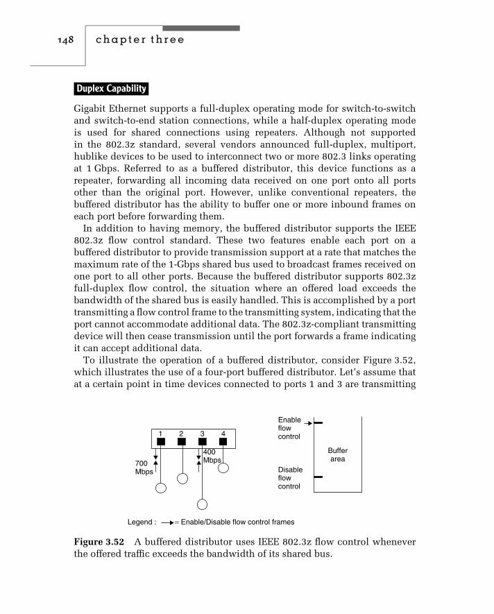
148 c h a p t e r t h r e e
Duplex Capability
Gigabit Ethernet supports a full-duplex operating mode for switch-to-switchand switch-to-end station connections, while a half-duplex operating modeis used for shared connections using repeaters. Although not supportedin the 802.3z standard, several vendors announced full-duplex, multiport,hublike devices to be used to interconnect two or more 802.3 links operatingat 1 Gbps. Referred to as a buffered distributor, this device functions as arepeater, forwarding all incoming data received on one port onto all portsother than the original port. However, unlike conventional repeaters, thebuffered distributor has the ability to buffer one or more inbound frames oneach port before forwarding them.
In addition to having memory, the buffered distributor supports the IEEE802.3z flow control standard. These two features enable each port on abuffered distributor to provide transmission support at a rate that matches themaximum rate of the 1-Gbps shared bus used to broadcast frames received onone port to all other ports. Because the buffered distributor supports 802.3zfull-duplex flow control, the situation where an offered load exceeds thebandwidth of the shared bus is easily handled. This is accomplished by a porttransmitting a flow control frame to the transmitting system, indicating that theport cannot accommodate additional data. The 802.3z-compliant transmittingdevice will then cease transmission until the port forwards a frame indicatingit can accept additional data.
To illustrate the operation of a buffered distributor, consider Figure 3.52,which illustrates the use of a four-port buffered distributor. Let’s assume thatat a certain point in time devices connected to ports 1 and 3 are transmitting
1 2 3 4
700Mbps
400Mbps
Enableflowcontrol
Disableflowcontrol
Bufferarea
Legend : = Enable/Disable flow control frames
Figure 3.52 A buffered distributor uses IEEE 802.3z flow control wheneverthe offered traffic exceeds the bandwidth of its shared bus.

ethernet networks 149
data to the buffered distributor at 700 Mbps and 400 Mbps, respectively. Itshould be noted that those data rates represent traffic carried and not theoperating rate of those devices which would be 1 Gbps. Because the aggregaterate exceeds 1 Gbps, a normal repeater would not be able to support thistraffic load. However, a buffered repeater includes a memory buffer area intowhich the excessive 100-Mbps transmission (1100 − 1000) rapidly fills. Toinsure that its buffers do not overflow, the buffered repeater will issue a flowcontrol signal telling the transmitters to reduce their transmission rate. Thisflow control signal will occur once the occupancy of the buffer reaches apredefined level of occupancy, as indicated in the right portion of Figure 3.52.Once data from the buffer is serviced to the point where occupancy is at apredefined low level, the buffered distributor will use flow control to enabletransmission to the distributor by disabling flow control.
To provide an equitable method for sharing the 1-Gbps bus, the buffereddistributor uses a round-robin algorithm to determine which port can transmitonto the bus. This round-robin method occurs one frame at a time, withport 1 serviced, followed by port 2, and so on. Through the use of a buffereddistributor, it becomes possible to support applications that require a many-to-one transmission capability, such as a LAN with a local server used for graphicdatabase queries, e-mail, and similar applications. Instead of migrating theLAN to a switch environment, a buffered distributor may represent anotherpossible network solution to network bottlenecks for power users.
3.6 10 Gigabit Ethernet
The focus of this section is upon the next generation Ethernet standard, whichincreases the CSMA/CD operating rate to 10 Gbps. In this section we willexamine the rationale for 10 Gbps Ethernet, its architecture and expectedoperating rates.
Rationale
For many organizations it is hard to imagine the need for transporting dataat 1 Gbps. For other organizations Gigabit Ethernet represents a needed butinsufficient transport capability to satisfy existing or evolving communicationsrequirements. As we noted in the prior section in this chapter, the use of1000BASE-LH provides a transmission distance of 70 km and extends GigabitEthernet into the wide area network. This makes Gigabit Ethernet a viabletransport for use by communications carriers. However, because such carrierstransport information from numerous organizations over the WAN, Gigabit
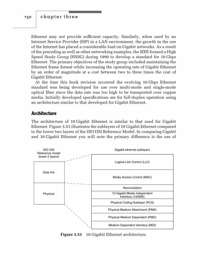
150 c h a p t e r t h r e e
Ethernet may not provide sufficient capacity. Similarly, when used by anInternet Service Provider (ISP) in a LAN environment, the growth in the useof the Internet has placed a considerable load on Gigabit networks. As a resultof the preceding as well as other networking examples, the IEEE formed a HighSpeed Study Group (HSSG) during 1999 to develop a standard for 10 GbpsEthernet. The primary objectives of the study group included maintaining theEthernet frame format while increasing the operating rate of Gigabit Ethernetby an order of magnitude at a cost between two to three times the cost ofGigabit Ethernet.
At the time this book revision occurred the evolving 10 Gbps Ethernetstandard was being developed for use over multi-mode and single-modeoptical fiber since the data rate was too high to be transported over coppermedia. Initially developed specifications are for full-duplex operation usingan architecture similar to that developed for Gigabit Ethernet.
Architecture
The architecture of 10 Gigabit Ethernet is similar to that used for GigabitEthernet. Figure 3.53 illustrates the sublayers of 10 Gigabit Ethernet comparedto the lower two layers of the ISO OSI Reference Model. In comparing Gigabitand 10 Gigabit Ethernet you will note the primary difference is the use of
ISO OSIReference model(lower 2 layers)
Data link
Physical
Gigabit ethernet sublayers
Logical Link Control (LLC)
Media Access Control (MAC)
Reconciliation
10 Gigabit Media IndependentInterface (10GMII)
Physical Coding Sublayer (PCS)
Physical Medium Attachment (PMA)
Physical Medium Dependent (PMD)
Medium Dependent Interface (MDI)
Figure 3.53 10 Gigabit Ethernet architecture.

ethernet networks 151
a 10 Gigabit Ethernet Media Independent Interface (10 GMII) for 10 GigabitEthernet. Similar to the GMII used by Gigabit Ethernet, the 10 GMII providesan interface between the MAC and the physical layer, isolating each fromone another.
A key difference between the 10 GMII and the GMII is the width of thedata path between the MAC sublayer and the physical layer. Under GigabitEthernet the GMII data bus is 8 bits in width. Under 10 GMII a 32-bit data pathis used. Figure 3.54 illustrates the structure of the 10 GMII used for 10 GigabitEthernet. Note that the actual signal interface is 72 bits in width. That signalinterface includes 32-bit data paths for transmit and receive and four controlbits to govern transmission and reception. In addition to the signal interfacethe 10 GMII includes two clocking lines and a TX−word−hold lines.
The TX−word−hold line is used to support word-oriented pacing. The 32-bitdata paths provide transmit and receive functions that employ four controlbits, with one control bit used for each 8-bit data byte. A control bit is setto 1 for denoting delimiters and special characters and to a binary 0 for data.Examples of delimiter and special characters include:
♦ IDLE used during inter-packet gap and when there is no data to transmit.♦ SOP used to indicate the start of each packet.♦ EOP used to indicate the end of each packet.♦ ERROR used to indicate the detection of an error in the received signal
or when an error condition needs to be transmitted.
Returning our attention to the architecture of 10 Gigabit Ethernet, the physi-cal coding sublayer (PCS) is responsible for coding and decoding data streamsflowing to and from the MAC layer. The PCS layer uses 8B/10B coding
MAClayer
Physicallayer
TX_word_hold
TX_clock
RX_clock
4 control bits
4 control bits
32 data bits
32 data bits
Figure 3.54 The 10 GMII.

152 c h a p t e r t h r e e
employed by Gigabit Ethernet, which was originally developed by IBM. Incomparison, the Physical Medium Attachment (PMA) sublayer is responsiblefor taking parallel data and serializing code groups into a bit stream suit-able for serial bit-oriented communications as well as performing the reverseoperation. In doing so the PMA is also responsible for providing applicablesynchronization. Below the PMA is the Physical Medium Dependent (PMD)sublayer. The PMD is responsible for signal transmission to include amplifi-cation, modulation and wave shaping. Optical transceivers can be consideredto represent devices that operate at the PMD sublayer. Different PMD sub-layers can be expected to be employed to support different types of media.In fact, at the time this book revision was prepared the IEEE 802.3ae TaskForce had developed a draft standard that requires the support of four dis-tinct link distances over different types of optical fiber. To meet the TaskForce distance objectives required four PMDs, as indicated in Table 3.14. Inexamining the entries in Table 3.14 you will note the Task Force selected twoversions of wide wavelength division multiplexing. A 1310 nanometer (nm)version was selected for use over single-mode fiber to provide a transmissiondistance of 10 km, while a 1310 nm PMD was selected to provide a drive dis-tance of 300 meters over multimode fiber. The latter PMD recognizes the factthat many organizations have existing multimode fiber and its replacementwould represent an expenditure of time and material, so the ability to run10 Gigabit Ethernet over existing multimode fiber became an objective of theIEEE Task Force.
The use of 850 nm laser over multimode fiber also provides organizationswith an upgrade path without having to change their cabling infrastructure.The selection of a 1550 nm laser to provide a link transmission of 40 kmprovides a mechanism to use 10 Gigabit Ethernet in metropolitan as well asprivate long-distance applications.
TABLE 3.14 10 Gigabit PMD Support
OpticalTransceiver
Type of FiberSupported
Target TransmissionDistance
850 nm serial Multi-mode 65 m
1310 nm WWDM Multi-mode 300 m
1310 nm WWDM Single mode 10 km
1310 nm serial Single mode 10 km
1550 nm serial Single mode 40 km

ethernet networks 153
Returning our attention to the 10 Gigabit Ethernet architecture shown inFigure 3.53, the Media Dependent Interface (MDI) provides the connector to aparticular media.
Operating Rates
While it would appear that the specifications of a data rate for 10 Gbps Ethernetwould be simple task, in actuality it wasn’t. While proponents of the use of10 Gbps Ethernet in a LAN environment want the data rate to be ten timesthe 1 Gbps Ethernet rate, proponents of the use of 10 Gbps Ethernet in theWAN prefer the optical carrier (OC)-192 data payload rate of approximately9.29 Gbps. Due to the diligent requirements of LAN and WAN proponents of10 Gigabit Ethernet, it appears that both operating rates will be supported bythe evolving standard.


c h a p t e r f o u r
Frame OperationsIn this chapter, we will first focus our attention on the composition ofdifferent types of Ethernet frames. In reality, there is only one physicalEthernet frame. However, the composition of the frame was altered by theIEEE when the CSMA/CD original Ethernet frame format was standardizedby that organization as the 802.3 frame. In addition, the logical compositionof the data field within the 802.3 frame can vary based upon the protocoltransported.
Once we obtain an understanding of the composition of Ethernet and IEEE802.3 frames, we will examine the function of fields within each frame, as wellas the manner in which the placement of frames on the media is controlled — aprocess known as media access control. After this is accomplished, we willturn our attention to the manner by which protocol information is carriedwithin an IEEE 802.3 frame to include logical link control (LLC), NetWare,TCP/IP, and other protocols.
Although the composition of the IEEE 802.3 frame remains the same from10-Mbps through 10-Gbps operations, there are certain restrictions on theframing of frames and the minimum size of the information field at differentnetwork operating rates. Thus, in the last two sections in this chapter, we willexamine certain modifications and restrictions on frames transported on FastEthernet and Gigabit and 10 Gigabit Ethernet networks.
4.1 Frame Composition
Figure 4.1 illustrates the general frame composition of Ethernet and IEEE802.3 frames. You will note that they differ slightly. An Ethernet frame con-tains an eight-byte preamble, while the IEEE 802.3 frame contains a seven-bytepreamble followed by a one-byte start-of-frame delimiter field. A second dif-ference between the composition of Ethernet and IEEE 802.3 frames concerns
155

156 c h a p t e r f o u r
Ethernet
Preamble
Preamble
Destinationaddress
Sourceaddress Type Data Frame check
sequence
8 bytes 6 bytes 6 bytes
7 bytes 1 byte 2/6 bytes 2/6 bytes
2 bytes
2 bytes
46–1500 bytes
46–1500 bytes
4 bytes
4 bytes
IEEE 802.3
Start offrame
delimiter
Destinationaddress
Sourceaddress Length Data Frame check
sequence
Figure 4.1 Ethernet and IEEE 802.3 frame formats.
the two-byte Ethernet type field. That field is used by Ethernet to specifythe protocol carried in the frame, enabling several protocols to be carriedindependently of one another. Under the IEEE 802.3 frame format, the typefield was replaced by a two-byte length field, which specifies the number ofbytes that follow that field as data.
The differences between Ethernet and IEEE 802.3 frames, while minor, makethe two incompatible with one another. This means that your network mustcontain either all Ethernet-compatible NICs or all IEEE 802.3–compatibleNICs. Fortunately, the fact that the IEEE 802.3 frame format represents astandard means that almost all vendors now market 802.3-compliant hardwareand software. Although a few vendors continue to manufacture Ethernet ordual functioning Ethernet/IEEE 802.3 hardware, such products are primarilyused to provide organizations with the ability to expand previously developednetworks without requiring the wholesale replacement of NICs. Although theIEEE 802.3 frame does not directly support a type field within the frame, as wewill note in Section 4 in this chapter, the IEEE defined a special type of frameto obtain compatibility with Ethernet LANs. That frame is referred to as anEthernet Subnetwork Access Protocol (Ethernet-SNAP) frame, which enablesa type subfield to be included in the data field. While the IEEE 802.3 standardhas essentially replaced Ethernet, because of their similarities and the factthat 802.3 was based upon Ethernet, we will consider both to be Ethernet.
Now that we have an overview of the structure of Ethernet and 802.3 frames,let’s probe more deeply and examine the composition of each frame field. Wewill take advantage of the similarity between Ethernet and IEEE 802.3 framesto examine the fields of each frame on a composite basis, noting the differencesbetween the two when appropriate.

frame operations 157
Preamble Field
The preamble field consists of eight (Ethernet) or seven (IEEE 802.3) bytes ofalternating 1 and 0 bits. The purpose of this field is to announce the frameand to enable all receivers on the network to synchronize themselves to theincoming frame.
Start-of-Frame Delimiter Field
This field is applicable only to the IEEE 802.3 standard and can be viewed asa continuation of the preamble. In fact, the composition of this field continuesin the same manner as the format of the preamble, with alternating 1 and0 bits used for the first six bit positions of this one-byte field. The last twobit positions of this field are 11 — this breaks the synchronization pattern andalerts the receiver that frame data follows.
Both the preamble field and the start-of-frame delimiter field are removedby the controller when it places a received frame in its buffer. Similarly, whena controller transmits a frame, it prefixes the frame with those two fields (if itis transmitting an IEEE 802.3 frame) or a preamble field (if it is transmitting atrue Ethernet frame).
Destination Address Field
The destination address identifies the recipient of the frame. Although thismay appear to be a simple field, in reality its length can vary between IEEE802.3 and Ethernet frames. In addition, each field can consist of two ormore subfields, whose settings govern such network operations as the type ofaddressing used on the LAN, and whether the frame is addressed to a specificstation or more than one station. To obtain an appreciation for the use of thisfield, let’s examine how this field is used under the IEEE 802.3 standard asone of the two field formats applicable to Ethernet.
Figure 4.2 illustrates the composition of the source and destination addressfields. As indicated, the two-byte source and destination address fields areapplicable only to IEEE 802.3 networks, while the six-byte source and desti-nation address fields are applicable to both Ethernet and IEEE 802.3 networks.A user can select either a two- or six-byte destination address field; how-ever, with IEEE 802.3 equipment, all stations on the LAN must use the sameaddressing structure. Today, almost all 802.3 networks use six-byte address-ing, because the inclusion of a two-byte field option was designed primarilyto accommodate early LANs that use 16-bit address fields.

158 c h a p t e r f o u r
(a) 2 byte field (IEEE 802.3)
I/G*
I/G*
15 address bits
46 address bits
(b) 6 byte field (ethernet and IEEE 802.3)
U/L
I/G bit subfield '0' = individual address '1' = group addressU/L bit subfield '0' = universally administrated addressing
'1' = locally administrated addressing
* Set to '0' in source address field
48 bit address field
16 bit address field
Figure 4.2 Source and destination address field formats.
Both destination and source addresses are normally displayed by networkmonitors in hexadecimal, with the first three bytes separated from the lastthree by a colon (:) when six-byte addressing is used. For example, the sourceaddress 02608C876543 would be displayed as 02608C:876543. As we willshortly note, the first three bytes identify the manufacturer of the adaptercard, while the following three bytes identify a specific adapter manufacturedby the vendor identified by the first three bytes or six hex digits.
I/G Subfield
The one-bit I/G subfield is set to a 0 to indicate that the frame is destined toan individual station, or 1 to indicate that the frame is addressed to more thanone station — a group address. One special example of a group address is theassignment of all 1s to the address field. Hex ‘‘FFFFFFFFFFFF’’ is recognizedas a broadcast address, and each station on the network will receive andaccept frames with that destination address.
An example of the use of a broadcast destination address is the serviceadvertising packet (SAP) transmitted every 60 seconds by NetWare servers.The SAP is used to inform other servers and workstations on the network ofthe presence of that server. Because the SAP uses a destination address ofFF-FF-FF-FF-FF-FF, it is recognized by every node on the network.

frame operations 159
When a destination address specifies a single station, the address is referredto as a unicast address. A group address that defines multiple stations isknown as a multicast address, while a group address that specifies all stationson the network is, as previously mentioned, referred to as a broadcast address.
U/L Subfield
The U/L subfield is applicable only to the six-byte destination address field.The setting of this field’s bit position indicates whether the destination addressis an address that was assigned by the IEEE (universally administered) orassigned by the organization via software (locally administered).
Universal versus Locally Administered Addressing
Each Ethernet NIC contains a unique address burned into its read-only memory(ROM) at the time of manufacture. To ensure that this universally administeredaddress is not duplicated, the IEEE assigns blocks of addresses to eachmanufacturer. These addresses normally include a three-byte prefix, whichidentifies the manufacturer and is assigned by the IEEE, and a three-bytesuffix, which is assigned by the adapter manufacturer to its NIC. For example,the prefix 02608C identifies an NIC manufactured by 3Com, while a prefix ofhex 08002 identifies an NIC manufactured by Digital Equipment Company,which was acquired by compaq computer.
Although the use of universally administered addressing eliminates thepotential for duplicate network addresses, it does not provide the flexibilityobtainable from locally administered addressing. For example, under locallyadministered addressing, you can configure mainframe software to work witha predefined group of addresses via a gateway PC. Then, as you add newstations to your LAN, you simply use your installation program to assign alocally administered address to the NIC instead of using its universally admin-istered address. As long as your mainframe computer has a pool of locallyadministered addresses that includes your recent assignment, you do not haveto modify your mainframe communications software configuration. Becausethe modification of mainframe communications software typically requiresrecompiling and reloading, the attached network must become inoperative fora short period of time. Because a large mainframe may service hundreds tothousands of users, such changes are normally performed late in the evening oron a weekend. Thus, the changes required for locally administered addressingare more responsive to users accessing certain types of mainframe computersthan those required for universally administered addressing.

160 c h a p t e r f o u r
Source Address Field
The source address field identifies the station that transmitted the frame. Likethe destination address field, the source address can be either two or six bytesin length.
The two-byte source address is supported only under the IEEE 802.3 stan-dard and requires the use of a two-byte destination address; all stations onthe network must use two-byte addressing fields. The six-byte source addressfield is supported by both Ethernet and the IEEE 802.3 standard. When asix-byte address is used, the first three bytes represent the address assignedby the IEEE to the manufacturer for incorporation into each NIC’s ROM. Thevendor then normally assigns the last three bytes for each of its NICs.
Table 4.1 lists the NIC identifiers for 85 Ethernet card manufacturers.Note that many organizations including Cisco Systems, 3Com, IBM, MIPS,Ungermann-Bass, and Data General were assigned two or more blocks ofaddresses by the IEEE. Also note that organizations listed in Table 4.1 rangein scope from well-known communications and computer manufacturers touniversities and even a commercial firm probably best known for its watchcommercials. The entries in Table 4.1 represent a portion of three-byte identi-fiers assigned by the IEEE over the past decade and do not include identifierscurrently assigned to all vendors. For a comprehensive list of currentlyassigned three-byte identifiers, readers should contact the IEEE. You cancontact the IEEE at:
IEEE Standards Department
445 Hoes Lane
P.O. Box 1331
Piscataway, NJ 08855
Telephone: +1 (732) 562-3813
Fax: +1 (732) 562-1571
Many software- and hardware-based network analyzers include the capabil-ity to identify each station on a LAN, count the number of frames transmittedby the station and destined to the station, as well as identify the manufac-turer of the NIC used in the station. Concerning the latter capability, this isaccomplished by the network analyzer containing a table of three-byte identi-fiers assigned by the IEEE to each NIC manufacturer, along with the name ofthe manufacturer. Then the analyzer compares the three-byte identifier readfrom frames flowing on the network and compares each identifier with the

frame operations 161
TABLE 4.1 Representative Ethernet NIC Manufacturer IDs
NIC Manufacturer Three-Byte Identifier
Cisco 00-00-0C
Fujitsu 00-00-0E
Cabletron 00-00-1D
NeXT 00-00-0F
TRW 00-00-2A
Hughes LAN Systems 00-00-10(formerly Sytek)
Tektronix 00-00-11
Datapoint Corporation 00-00-15
Olicom 00-00-24
AT&T 00-00-3D
NEC 00-00-4C
Network General 00-00-65
MIPS 00-00-6B
Madge Networks 00-00-6F
MIPS 00-00-77
Proteon 00-00-93
Cross Com Communications 00-00-98(now part of Olicom)
Wellfleet (now Bay Networks) 00-00-A2
Xerox 00-00-AA
RND (RAD Network Devices) 00-00-B0
Western Digital 00-00-C0
Emulex 00-00-C9
Develcon Electronics, Ltd. 00-00-D0
Adaptec, Inc. 00-00-D1
Gandalf Data Ltd. 00-00-F3
Allied Telesis, Inc. 00-00-F4

162 c h a p t e r f o u r
TABLE 4.1 (Continued)
NIC Manufacturer Three-Byte Identifier
Racal Datacom 00-07-01
XYlan 00-20-DA
Crescendo (now owned by Cisco) 00-40-OB
Ascom 00-40-15
AST Research 00-40-1C
Netcomm 00-40-28
Nokia Data Communications 00-40-43
Cable and Wireless 00-40-74
AMP Incorporated 00-40-76
DigiBoard 00-40-9D
Cray Research, Inc. 00-40-A6
Mocom Communications Corp. 00-40-C5
PlainTree Systems, Inc. 00-40-EA
3Com 00-60-08
Cisco Systems, Inc. 00-60-09
Cisco Systems, Inc. 00-60-2F
Cisco Systems, Inc. 00-60-3E
Cisco Systems, Inc. 00-60-5C
Cisco Systems, Inc. 00-60-70
Cisco Systems, Inc. 00-60-83
3Com 00-60-8C
3Com 00-60-97
Hewlett-Packard 00-60-BO
Thomas Conrad Corporation 00-80-13
Bell Atlantic 00-80-1A
Newbridge Networks Corporation 00-80-21
Kalpana (acquired by Cisco) 00-80-24

frame operations 163
TABLE 4.1 (Continued)
NIC Manufacturer Three-Byte Identifier
University of Toronto 00-80-46
Compaq Computer Corporation 00-80-5F
Nippon Steel Corporation 00-80-6E
Xircom, Inc. 00-80-C7
Shiva 00-80-D3
Zenith Communications Products 00-80-F7
Azure Technologies, Inc. 00-80-FE
Bay Networks 00-A0-00
National Semiconductor 00-A0-D1
Allied Telesyn 00-A0-D2
Intel 00-AA-00
Ungermann-Bass 00-DD-00
Ungermann-Bass 00-DD-01
Racal Interlan 02-07-01
3Com 02-60-8C
BBN 08-00-08
Hewlett Packard 08-00-09
Unisys 08-00-0B
Tektronix 08-00-11
Data General 08-00-A
Data General 08-00-1B
Sun 08-00-20
DEC 08-00-2B
Bull 08-00-38
Sony 08-00-46
Sequent 08-00-47
Stanford University 08-00-56

164 c h a p t e r f o u r
TABLE 4.1 (Continued)
NIC Manufacturer Three-Byte Identifier
IBM 08-00-5A
Silicon Graphics 08-00-69
Silicon Graphics 08-00-79
Seiko 08-00-83
Excelan 08-00-6E
Danish Data Elektronix 08-00-75
AT&T 80-00-10
identifiers stored in its identifier table. By providing information concerningnetwork statistics, network errors, and the vendor identifier for the NIC ineach station, you may be able to isolate problems faster or better considerfuture decisions concerning the acquisition of additional NICs.
An example of the use of NIC manufacturer IDs can be obtained by exam-ining two monitoring screen displays of the Triticom EtherVision networkmonitoring and analysis program. Figure 4.3 illustrates the monitoring screenduring the program’s autodiscovery process. During this process the programreads the source address of each frame transmitted on the segment that thecomputer executing the program is connected to. Although obscured by thehighlighted bar, the first three bytes of the adapter address first discoveredis 00-60-8C, which represents a block of addresses assigned by the IEEE to 3Com Corporation. If you glance at the first column in Figure 4.3, you will notethat the second row, fourth row, ninth row, and a few additional rows alsohave NIC addresses that commence with hex 00-60-8C. By pressing the F2 keythe program will display the manufacturer of each NIC encountered and forwhich statistics are being accumulated. This is indicated in Figure 4.4, whichshows the first three bytes of each address replaced by the vendor assignedto the appropriate manufacturer ID. Thus, rows 1, 4, 9, and a few other rowscommence with ‘‘3Com’’ to indicate the manufacturer of the NIC.
Organizations can request the assignment of a vendor code by contactingthe IEEE Registration Authority at the previously listed address for the IEEEprovided in this section. A full list of assigned vendor codes is obtainable byFTP at ftp.ieee.org as the file ieee/info/info.stds.oui. Readers should note thatthe list is limited to those companies that agreed to make their vendor codeassignment(s) public.
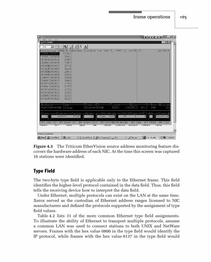
frame operations 165
Figure 4.3 The Triticom EtherVision source address monitoring feature dis-covers the hardware address of each NIC. At the time this screen was captured16 stations were identified.
Type Field
The two-byte type field is applicable only to the Ethernet frame. This fieldidentifies the higher-level protocol contained in the data field. Thus, this fieldtells the receiving device how to interpret the data field.
Under Ethernet, multiple protocols can exist on the LAN at the same time.Xerox served as the custodian of Ethernet address ranges licensed to NICmanufacturers and defined the protocols supported by the assignment of typefield values.
Table 4.2 lists 31 of the more common Ethernet type field assignments.To illustrate the ability of Ethernet to transport multiple protocols, assumea common LAN was used to connect stations to both UNIX and NetWareservers. Frames with the hex value 0800 in the type field would identify theIP protocol, while frames with the hex value 8137 in the type field would

166 c h a p t e r f o u r
Figure 4.4 By pressing the F2 key, EtherVision will convert the three-bytehex NIC manufacturer ID to the vendor name or an appropriate mnemonic.
identify the transport of IPX and SPX protocols. Thus, the placement of anappropriate hex value in the Ethernet type field provides a mechanism tosupport the transport of multiple protocols on the local area network.
Under the IEEE 802.3 standard, the type field was replaced by a length field,which precludes compatibility between pure Ethernet and 802.3 frames.
Length Field
The two-byte length field, applicable to the IEEE 802.3 standard, defines thenumber of bytes contained in the data field. Under both Ethernet and IEEE802.3 standards, the minimum size frame must be 64 bytes in length frompreamble through FCS fields. This minimum size frame ensures that thereis sufficient transmission time to enable Ethernet NICs to detect collisionsaccurately, based on the maximum Ethernet cable length specified for anetwork and the time required for a frame to propagate the length of the cable.

frame operations 167
TABLE 4.2 Representative Ethernet Type Field Assignments
Protocol Hex Value Assigned
Experimental 0101-DIFF
Xerox XNS 0600
IP 0800
X.75 Internet 0801
NBS Internet 0802
ECMA Internet 0803
CHAOSmet 0804
X.25 Level 3 0805
Address Resolution Protocol 0806
XNS Compatibility 0807
Banyan Systems 0BAD
BBN Simnet 5208
DEC MOP Dump/Load 6001
DEC MOP Remote Console 6002
DEC DECNET Phase IV Route 6003
DEC LAT 6004
DEC Diagnostic Protocol 6005
3Com Corporation 6010–6014
Proteon 7030
AT&T 8008
Excelan 8010
Tymshare 802E
DEC LANBridge 8038
DEC Ethernet Encryption 803D
AT&T 8046–8047
AppleTalk 809B
IBM SNA Service on Ethernet 80D5
AppleTalk ARP 80F3
Wellfleet 80FF–8103
NetWare IPX/SPX 8137–8138
SNMP 814C

168 c h a p t e r f o u r
Based on the minimum frame length of 64 bytes and the possibility of usingtwo-byte addressing fields, this means that each data field must be a minimumof 46 bytes in length. The only exception to the preceding involves GigabitEthernet. At a 1000-Mbps operating rate the original 802.3 standard wouldnot provide a frame duration long enough to permit a 100-meter cable runover copper media. This is because at a 1000-Mbps data rate there is a highprobability that a station could be in the middle of transmitting a frame beforeit becomes aware of any collision that might have occurred at the other endof the segment. Recognizing this problem resulted in the development of acarrier extension, which extends the minimum Ethernet frame to 512 bytes.The carrier extension is discussed in detail in Section 4.6 when we turn ourattention to the Gigabit Ethernet carrier extension.
For all versions of Ethernet except Gigabit Ethernet, if data being transportedis less than 46 bytes, the data field is padded to obtain 46 bytes. However, thenumber of PAD characters is not included in the length field value. NICs thatsupport both Ethernet and IEEE 802.3 frame formats use the value in this fieldto distinguish between the two frames. That is, because the maximum lengthof the data field is 1,500 bytes, a value that exceeds hex 05DC indicates thatinstead of a length field (IEEE 802.3), the field is a type field (Ethernet).
Data Field
As previously discussed, the data field must be a minimum of 46 bytes inlength to ensure that the frame is at least 64 bytes in length. This means thatthe transmission of 1 byte of information must be carried within a 46-bytedata field; if the information to be placed in the field is less than 46 bytes, theremainder of the field must be padded. Although some publications subdividethe data field to include a PAD subfield, the latter actually represents optionalfill characters that are added to the information in the data field to ensure alength of 46 bytes. The maximum length of the data field is 1500 bytes.
Frame Check Sequence Field
The frame check sequence field, applicable to both Ethernet and the IEEE802.3 standard, provides a mechanism for error detection. Each transmittercomputes a cyclic redundancy check (CRC) that covers both address fields, thetype/length field, and the data field. The transmitter then places the computedCRC in the four-byte FCS field.
The CRC treats the previously mentioned fields as one long binary number.The n bits to be covered by the CRC are considered to represent the coefficients

frame operations 169
of a polynomial M(X) of degree n − 1. Here, the first bit in the destinationaddress field corresponds to the Xn−1 term, while the last bit in the data fieldcorresponds to the X0 term. Next, M(X) is multiplied by X32, and the result ofthat multiplication process is divided by the following polynomial:
G(X)=X32+X26+X23+X22+X16+X12+X11+X10+X8+X7+X5+X4+X2+X+1
Note that the term Xn represents the setting of a bit to a 1 in position n. Thus,part of the generating polynomial X5 + X4 + X2 + X1 represents the binaryvalue 11011.
This division produces a quotient and remainder. The quotient is discarded,and the remainder becomes the CRC value placed in the four-byte FCS field.This 32-bit CRC reduces the probability of an undetected error to 1 bit in every4.3 billion, or approximately 1 bit in 232 − 1 bits.
Once a frame reaches its destination, the receiver uses the same polynomialto perform the same operation upon the received data. If the CRC computedby the receiver matches the CRC in the FCS field, the frame is accepted.Otherwise, the receiver discards the received frame, as it is considered to haveone or more bits in error. The receiver will also consider a received frame tobe invalid and discard it under two additional conditions. Those conditionsoccur when the frame does not contain an integral number of bytes, or whenthe length of the data field does not match the value contained in the lengthfield. The latter condition obviously is only applicable to the 802.3 standard,because an Ethernet frame uses a type field instead of a length field.
Interframe Gap
Under the 10-Mbps versions of the CSMA/CD protocol a 9.6 microsecond(µs) quiet time occurs between transmitted frames. This quiet time, whichis referred to as an interframe gap, permits clocking circuitry used withinrepeaters and workstations and hub ports to be resynchronized to the knownlocal clock. Under Fast Ethernet the interframe gap is 0.96 ms, while underGigabit Ethernet the gap is reduced to 0.096 ms.
4.2 Media Access Control
In the first section in this chapter, we examined the frame format by whichdata is transported on an Ethernet network. Under the IEEE 802 series of10-Mbps operating standards, the data link layer of the OSI Reference Model

170 c h a p t e r f o u r
is subdivided into two sublayers — logical link control (LLC) and mediumaccess control (MAC). The frame formats examined in Section 4.1 representthe manner in which LLC information is transported. Directly under the LLCsublayer is the MAC sublayer. The MAC sublayer, which is the focus of thissection, is responsible for checking the channel and transmitting data if thechannel is idle, checking for the occurrence of a collision, and taking a seriesof predefined steps if a collision is detected. Thus, this layer provides therequired logic to control the network.
Figure 4.5 illustrates the relationship between the physical and LLC layerswith respect to the MAC layer. The MAC layer is an interface between userdata and the physical placement and retrieval of data on the network. To betterunderstand the functions performed by the MAC layer, let us examine thefour major functions performed by that layer — transmitting data operations,transmitting medium access management, receiving data operations, andreceiving medium access management. Each of those four functions can beviewed as a functional area, because a group of activities is associated with
LLC dataTransmit
Mediumaccess control
Mediumaccess control
Receive
Transmitdata
operations
Transmitmedium accessmanagement
Receivemedium accessmanagement
Receivedata
operations
Datadecoding
Dataencoding
Physicallayer
Channel
Figure 4.5 Medium access control. The medium access control (MAC) layercan be considered an interface between user data and the physical placementand retrieval of data on the network.
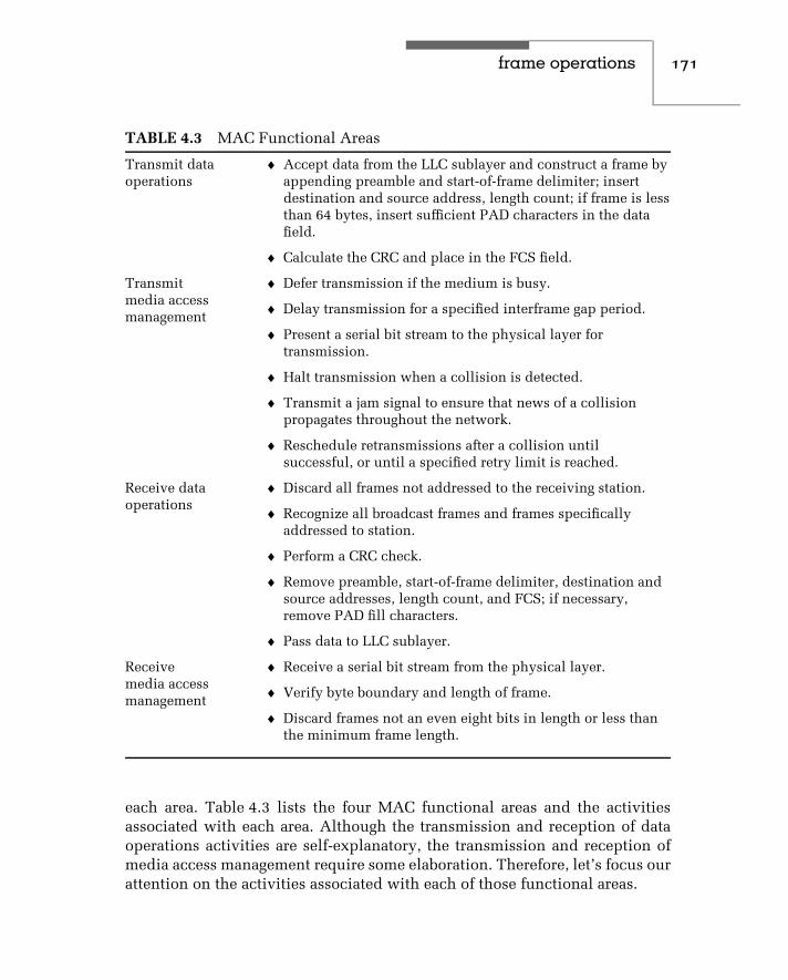
frame operations 171
TABLE 4.3 MAC Functional Areas
Transmit dataoperations
♦ Accept data from the LLC sublayer and construct a frame byappending preamble and start-of-frame delimiter; insertdestination and source address, length count; if frame is lessthan 64 bytes, insert sufficient PAD characters in the datafield.
♦ Calculate the CRC and place in the FCS field.
Transmitmedia accessmanagement
♦ Defer transmission if the medium is busy.
♦ Delay transmission for a specified interframe gap period.
♦ Present a serial bit stream to the physical layer fortransmission.
♦ Halt transmission when a collision is detected.
♦ Transmit a jam signal to ensure that news of a collisionpropagates throughout the network.
♦ Reschedule retransmissions after a collision untilsuccessful, or until a specified retry limit is reached.
Receive dataoperations
♦ Discard all frames not addressed to the receiving station.
♦ Recognize all broadcast frames and frames specificallyaddressed to station.
♦ Perform a CRC check.
♦ Remove preamble, start-of-frame delimiter, destination andsource addresses, length count, and FCS; if necessary,remove PAD fill characters.
♦ Pass data to LLC sublayer.
Receivemedia accessmanagement
♦ Receive a serial bit stream from the physical layer.
♦ Verify byte boundary and length of frame.
♦ Discard frames not an even eight bits in length or less thanthe minimum frame length.
each area. Table 4.3 lists the four MAC functional areas and the activitiesassociated with each area. Although the transmission and reception of dataoperations activities are self-explanatory, the transmission and reception ofmedia access management require some elaboration. Therefore, let’s focus ourattention on the activities associated with each of those functional areas.

172 c h a p t e r f o u r
Transmit Media Access Management
CSMA/CD can be described as a listen-before-acting access method. Thus,the first function associated with transmit media access management is tofind out whether any data is already being transmitted on the network and, ifso, to defer transmission. During the listening process, each station attemptsto sense the carrier signal of another station, hence the prefix carrier sense(CS) for this access method. Although broadband networks use RF modemsthat generate a carrier signal, a baseband network has no carrier signal inthe conventional sense of a carrier as a periodic waveform altered to conveyinformation. Thus, a logical question you may have is how the MAC sublayeron a baseband network can sense a carrier signal if there is no carrier. Theanswer to this question lies in the use of a digital signaling method, known asManchester encoding on 10-Mbps Ethernet LANs, that a station can monitorto note whether another station is transmitting. Although NRZI encoding isused on broadband networks, the actual data is modulated after it is encoded.Thus, the presence or absence of a carrier is directly indicated by the presenceor absence of a carrier signal on a broadband network.
Collision Detection
As discussed in Chapter 3, under Manchester encoding, a transition occursat the middle of each bit period. This transition serves as both a clockingmechanism, enabling a receiver to clock itself to incoming data, and asa mechanism to represent data. Under Manchester coding, a binary 1 isrepresented by a high-to-low transition, while a binary 0 is represented bya low-to-high voltage transition. Thus, an examination of the voltage on themedium of a baseband network enables a station to determine whether acarrier signal is present.
If a carrier signal is found, the station with data to transmit will continueto monitor the channel. When the current transmission ends, the station willthen transmit its data, while checking the channel for collisions. BecauseEthernet and IEEE 802.3 Manchester-encoded signals have a 1-volt averageDC voltage level, a collision results at an average DC level of 2 volts. Thus, atransceiver or network interface card can detect collisions by monitoring thevoltage level of the Manchester line signal.
Jam Pattern
If a collision is detected during transmission, the transmitting station willcease transmission of data and initiate transmission of a jam pattern. The jam

frame operations 173
pattern consists of 32 to 48 bits. These bits can have any value other thanthe CRC value that corresponds to the partial frame transmitted before thejam. The transmission of the jam pattern ensures that the collision lasts longenough to be detected by all stations on the network.
When a repeater is used to connect multiple segments, it must recognize acollision occurring on one port and place a jam signal on all other ports. Doingso results in the occurrence of a collision with signals from stations that mayhave been in the process of beginning to transmit on one segment when thecollision occurred on the other segment. In addition, the jam signal serves asa mechanism to cause nontransmitting stations to wait until the jam signalends before attempting to transmit, alleviating additional potential collisionsfrom occurring.
Wait Time
Once a collision is detected, the transmitting station waits a random number ofslot times before attempting to retransmit. The term slot represents 512 bits ona 10-Mbps network, or a minimum frame length of 64 bytes. The actual numberof slot times the station waits is selected by a randomization process, formallyknown as a truncated binary exponential backoff. Under this randomizationprocess, a randomly selected integer r defines the number of slot times thestation waits before listening to determine whether the channel is clear. If it is,the station begins to retransmit the frame, while listening for another collision.
If the station transmits the complete frame successfully and has additionaldata to transmit, it will again listen to the channel as it prepares another framefor transmission. If a collision occurs on a retransmission attempt, a slightlydifferent procedure is followed. After a jam signal is transmitted, the stationsimply doubles the previously generated random number and then waits theprescribed number of slot intervals before attempting a retransmission. Up to16 retransmission attempts can occur before the station aborts the transmissionand declares the occurrence of a multiple collision error condition.
Figure 4.6 illustrates the collision detection process by which a station candetermine that a frame was not successfully transmitted. At time t0 bothstations A and B are listening and fail to detect the occurrence of a collision,and at time t1 station A commences the transmission of a frame. As station A’sframe begins to propagate down the bus in both directions, station B beginsthe transmission of a frame, since at time t2 it appears to station B that thereis no activity on the network.
Shortly after time t2 the frames transmitted by stations A and B collide,resulting in a doubling of the Manchester encoded signal level for a very short

174 c h a p t e r f o u r
A B
A B
A B
A B
A B
t0
t1
t2
t3
t4
Stations A & B listening
Station A begins transmission
Station B begins transmission
Station B detects collision and transmits pattern jam
Station A detects collision before ending transmission
Figure 4.6 Collision detection.
period of time. This doubling of the Manchester encoded signal’s voltage levelis detected by station B at time t3, since station B is closer to the collision thanstation A. Station B then generates a jam pattern that is detected by station A.
Late Collisions
A late collision is a term used to reference the detection of a collision onlyafter a station places a complete frame on the network. A late collision isnormally caused by an excessive network segment cable length, resulting inthe time for a signal to propagate from one end of a segment to another part ofthe segment being longer than the time required to place a full frame on thenetwork. This results in two devices communicating at the same time neverseeing the other’s transmission until their signals collide.
A late collision is detected by a transmitter after the first slot time of64 bytes and is applicable only for frames whose lengths exceed 65 bytes. Thedetection of a late collision occurs in exactly the same manner as a normalcollision; however, it happens later than normal. Although the primary causeof late collisions is excessive segment cable lengths, an excessive number ofrepeaters, faulty connectors, and defective Ethernet transceivers or controllers

frame operations 175
can also result in late collisions. Many network analyzers provide informationon late collisions, which can be used as a guide to check the previouslymentioned items when late collisions occur.
Service Primitives
As previously mentioned, the MAC sublayer isolates the physical layer fromthe LLC sublayer. Thus, one of the functions of the MAC sublayer is to provideservices to the LLC. To accomplish this task, a series of service primitives wasdefined to govern the exchange of LLC data between a local MAC sublayerand its peer LLC sublayer.
The basic MAC service primitives used in all IEEE MAC standards includethe medium access data request (MA−DATA.request), medium access data con-firm (MA−DATA.confirm), medium access data indicate (MA−DATA.indicate),and medium access data response (MA−DATA.response).
MA−DATA.request
The medium access data request is generated whenever the LLC sublayerhas data to be transmitted. This primitive is passed from layer n to layern − 1 to request the initiation of service, and results in the MAC sublayerformatting the request in a MAC frame and passing it to the physical layer fortransmission.
MA−DATA.confirm
The medium access data confirm primitive is generated by the MAC sublayerin response to an MA−DATA.request generated by the local LLC sublayer.The confirm primitive is passed from layer n − 1 to layer n, and includes astatus parameter that indicates the outcome of the request primitive.
MA−DATA.indicate
The medium access data indicate primitive is passed from layer n − 1 tolayer n to indicate that a valid frame has arrived at the local MAC sublayer.Thus, this service primitive denotes that the frame was received without CRC,length, or frame-alignment error.
MA−DATA.response
The medium access data response primitive is passed from layer n to layern − 1. This primitive acknowledges the MA−DATA.indicate service primitive.

176 c h a p t e r f o u r
Primitive Operations
To illustrate the use of MAC service primitives, let us assume that sta-tion A on a network wants to communicate with station B. As illustrated inFigure 4.7, the LLC sublayer of station A requests transmission of a frame tothe MAC sublayer service interface via the issuance of an MA−DATA.requestservice primitive. In response to the MA−DATA.request, a frame is trans-mitted to station B. Upon receipt of that frame, the MAC sublayer at thatstation generates an MA−DATA.indicate to inform the LLC sublayer of thearrival of the frame. The LLC sublayer accepts the frame and generates anMA−DATA.response to inform the MAC sublayer that it has the frame. Thatresponse flows across the network to station A, where the MAC sublayer gen-erates an MA−DATA.confirm to inform the LLC sublayer that the frame wasreceived without error.
Half- versus Full-duplex Operation
Ethernet was originally designed as a half-duplex LAN transmission method.The CSMA/CD algorithm required the receive pair in the two pair wiring usedfor 10BASE-T to be used both to receive data and to detect collisions. In fact, ifthe transmit and receive wire pairs became simultaneously activated, the MAC
StationA
StationB
MACservice
interface
MACservice
interface
MA_DATA.request
MA_DATA.confirm
MA_DATA.indicate
MA_DATA.response
NETWORK
Figure 4.7 Relationship of medium access control service primitives.

frame operations 177
layer would cause the ongoing transmission to terminate and would initiatethe previously described truncated binary exponential backoff algorithm.
With the development of Ethernet switches during the mid-1980s, it becamepossible to cable a station to a switch port directly. When this operationoccurred it eliminated the possibility of a collision. Recognizing the fact thatthe CSMA/CD algorithm was not efficient for use in a switch environment,the IEEE assigned a task force to examine modifying the MAC layer for switchoperations. In 1987 the IEEE 802.3x standard was approved; this introduceda modified MAC layer that added support for full duplex operations ina switch environment. A related standard, referred to as the IEEE 802.3yspecification, defines a flow control mechanism, which is important whendevices with dissimilar operating rates communicate with one another througha switch, such as a server operating at 100 Mbps communicating with aworkstation operating at 10 Mbps. Although the Ethernet switch will includebuffer memory, to preclude such memory from being filled and subsequentdata transmitted by the server being lost, the switch will initiate flow control tothe server to temporarily stop its transmission. Once sufficient buffer memoryis available in the switch, flow control will be disabled. Later in this book wewill examine flow control in more detail.
4.3 Logical Link Control
As discussed in Chapter 2, the LLC sublayer was defined under the IEEE 802.2standard to make the method of link control independent of a specific accessmethod. Thus, the 802.2 method of link control spans Ethernet (IEEE 802.3),Token Bus (IEEE 802.4), and Token-Ring (IEEE 802.5) local area networks.Functions performed by the LLC include generating and interpreting com-mands to control the flow of data, including recovery operations for when atransmission error is detected.
Link control information is carried within the data field of an IEEE 802.3frame as an LLC protocol data unit (PDU). Figure 4.8 illustrates the relationshipbetween the IEEE 802.3 frame and the LLC PDU.
As discussed in Chapter 2, service access points (SAPs) function much likea mailbox. Because the LLC layer is bounded below the MAC sublayer andbounded above by the network layer, SAPs provide a mechanism for exchang-ing information between the LLC layer and the MAC and network layers. Forexample, from the network layer perspective, a SAP represents the place toleave messages about the services requested by an application. There are twobroad categories of SAPs, IEEE-administered and manufacturer-implemented.

178 c h a p t e r f o u r
PreambleStart offrame
delimiter
Destinationaddress
Sourceaddress
Length Data Frame checksequence
DSAP SSAP Control Information
Figure 4.8 Formation of LLC protocol data unit. Control information iscarried within a MAC frame.
TABLE 4.4 Representative Examples of SAP Addresses
Address (Hex) Assignment
IEEE-administered
00 Null SAP
02 Individual LLC sublayer management functions
06 ARPANET Internet Protocol (IP)
42 IEEE 802.1 Bridge-Spanning Tree Protocol
AA Sub-Network Access Protocol (SNAP)
FE ISO Network Layer Protocol
Manufacturer-implemented
80 Xerox Network Systems
BC Banyan VINES
EO Novell NetWare
FO IBM NetBIOS
F8 IBM Remote Program Load (RPL)
FA Ungermann-Bass
Table 4.4 provides six examples of each type of SAP. In examining theentries in Table 4.4, the hex value AA represents one of the more commonlyused SAPs today. When that value is encoded in both DSAP and SSAPfields, it indicates a special type of Ethernet frame referred to as an Ethernet

frame operations 179
SNAP frame. The SNAP frame, as we will shortly note when we coverit in Section 4.4, unlike the Ethernet 802.3 frame, enables several differentprotocols to be transported.
The destination services access point (DSAP) is one byte in length and isused to specify the receiving network layer process. Because an IEEE 802.3frame does not include a type field, the DSAP field is used to denote thedestination upper-layer protocol carried within the frame. For example, theDSAP hex value E0 indicates that the data field contains NetWare data.
The source service access point (SSAP) is also one byte in length. TheSSAP specifies the sending network layer process. Because the destinationand source protocols must be the same, the value of the SSAP field willalways match the value of the DSAP field. Both DSAP and SSAP addressesare assigned by the IEEE. For example, hex address ‘‘FF’’ represents a DSAPbroadcast address.
The control field contains information concerning the type and class ofservice being used for transporting LLC data. For example, a hex value of03 when NetWare is being transported indicates that the frame is using anunnumbered format for connectionless services.
Types and Classes of Service
Under the 802.2 standard, there are three types of service available for send-ing and receiving LLC data. These types are discussed in the next threeparagraphs. Figure 4.9 provides a visual summary of the operation of eachLLC service type.
Type 1
Type 1 is an unacknowledged connectionless service. The term connectionlessrefers to the fact that transmission does not occur between two devices asif a logical connection were established. Instead, transmission flows on thechannel to all stations; however, only the destination address acts uponthe data. As the name of this service implies, there is no provision for theacknowledgment of frames. Neither are there provisions for flow control orfor error recovery. Therefore, this is an unreliable service.
Despite those shortcomings, Type 1 is the most commonly used service,because most protocol suites use a reliable transport mechanism at the trans-port layer, thus eliminating the need for reliability at the link layer. In addition,by eliminating the time needed to establish a virtual link and the overheadof acknowledgments, a Type 1 service can provide a greater throughput thanother LLC types of services.

180 c h a p t e r f o u r
A
A
A
PDU
PDU
PDU
PDU = Protocol data unit
PDU
B
B
B
ACK
ACK
Type 3 acknowledged connectionless source
Type 1 unacknowledged connectionless service
Type 2 connection-oriented service
Legend:
ACK = AcknowledgmentA,B = Stations on the network
Figure 4.9 Local link control service types.
Type 2
The Type 2 connection-oriented service requires that a logical link be estab-lished between the sender and the receiver before information transfer. Oncethe logical connection is established, data will flow between the sender andreceiver until either party terminates the connection. During data transfer, aType 2 LLC service provides all of the functions lacking in a Type 1 service,using a sliding window for flow control. When IBM’s SNA data is transportedon a LAN, it uses connection-oriented services. Type 2 LLC is also commonlyreferred to as LLC 2.
Type 3
The Type 3 acknowledged connectionless service contains provision for thesetup and disconnection of transmission; it acknowledges individual framesusing the stop-and-wait flow control method. Type 3 service is primarilyused in an automated factory process-control environment, where one centralcomputer communicates with many remote devices that typically have alimited storage capacity.
Classes of Service
All logical link control stations support Type 1 operations. This level ofsupport is known as Class I service. The classes of service supported by

frame operations 181
LLC indicate the combinations of the three LLC service types supported bya station. Class I supports Type 1 service, Class II supports both Type 1 andType 2, Class III supports Type 1 and Type 3 service, and Class IV supportsall three service types. Because service Type 1 is supported by all classes,it can be considered a least common denominator, enabling all stations tocommunicate using a common form of service.
Service Primitives
The LLC sublayer uses service primitives similar to those that govern theexchange of data between the MAC sublayer and its peer LLC sublayer. In doingso, the LLC sublayer supports the Request, Confirm, Indicate, and Responseprimitives described in Section 4.2 of this chapter. The major differencebetween the LLC and MAC service primitives is that the LLC sublayer supportsthree types of services. As previously discussed, the available LLC servicesare unacknowledged connectionless, connection-oriented, and acknowledgedconnectionless. Thus, the use of LLC service primitives varies in conjunctionwith the type of LLC service initiated. For example, a connection-orientedservice uses service primitives in the same manner as that illustrated inFigure 4.7. If the service is unacknowledged connectionless, the only serviceprimitives used are the Request and Indicate, because there is no Responsenor Confirmation.
4.4 Other Ethernet Frame Types
Three additional frame types that warrant discussion are Ethernet-802.3,Ethernet-SNAP, and the IEEE 802.1Q tagged frame. In actuality, the first twotypes of frames represent a logical variation of the IEEE 802.3 frame, in whichthe composition of the data field varies from the composition of the LLCprotocol data unit previously illustrated in Figure 4.8. The third type of frameprovides the ability to form virtual LANs (vLANs) as well as to assign apriority level to a frame.
Ethernet-802.3
The Ethernet-802.3 frame represents a proprietary subdivision of theIEEE 802.3 data field to transport NetWare. Ethernet-802.3 is one of severaltypes of frames that can be used to transport NetWare. The actual frame typeused is defined at system setup by binding NetWare to a specific type of frame.

182 c h a p t e r f o u r
PreambleStart offrame
delimiter
Destinationaddress
Sourceaddress Length Data
Framecheck
sequence
IPX header Information
Figure 4.10 Novell’s NetWare Ethernet-802.3 frame. An Ethernet-802.3 framesubdivides the data field into an IPX header field and an information field.
Figure 4.10 illustrates the format of the Ethernet-802.3 frame. Due to theabsence of LLC fields, this frame is often referred to as raw 802.3.
For those using or thinking of using NetWare, a word of caution is in orderconcerning frame types. Novell uses the term Ethernet-802.2 to refer to theIEEE 802.3 frame. Thus, if you set up NetWare for Ethernet-802.2 frames, ineffect, your network is IEEE 802.3–compliant.
Ethernet-SNAP
The Ethernet-SNAP frame, unlike the Ethernet-802.3 frame, can be used totransport several protocols. AppleTalk Phase II, NetWare, and TCP/IP proto-cols can be transported due to the inclusion of an Ethernet type field in theEthernet-SNAP frame. Thus, SNAP can be considered as an extension thatpermits vendors to create their own Ethernet protocol transports. Ethernet-SNAP was defined by the IEEE 802.1 committee to facilitate interoperabilitybetween IEEE 802.3 LANs and Ethernet LANs. This was accomplished,as we will soon note, by the inclusion of a type field in the Ethernet-SNAP frame.
Figure 4.11 illustrates the format of an Ethernet-SNAP frame. Although theformat of this frame is based upon the IEEE 802.3 frame format, it does notuse DSAP and SSAP mailbox facilities and the control field. Instead, it placesspecific values in those fields to indicate that the frame is a SNAP frame.
The value hex AA is placed into the DSAP and SSAP fields, while hex 03 isplaced into the control field to indicate that a SNAP frame is being transported.

frame operations 183
PreambleStart offrame
delimiter
Destinationaddress
Sourceaddress Length Data
Framecheck
sequence
InformationDSAP SSAP Control Organizationcode
Ethernettype
(1) (1) (1) (3) (2)Bytes
Figure 4.11 Ethernet-SNAP frame format.
The hex 03 value in the control field defines the use of an unnumbered format,which is the only format supported by a SNAP frame.
The three-byte organization code field references the organizational bodythat assigned the value placed in the following field, the Ethernet type field.A hex value of 00-00-00 in the organization code field indicates that Xeroxassigned the value in the Ethernet type field. In comparison, a hex valueof 08-00-07 would indicate Apple computer as the organizational body thatassigned the valve in the following field. Concerning that following field,the SNAP frame uses two bytes to identify the protocol being transported,which significantly extends the number of protocols that can be transported.Although shown as the Ethernet Type field in Figure 4.11, the formal name forthis field is Protocol Identifier (PID). Through the use of the Ethernet-SNAPframe, you obtain the ability to transport multiple protocols in a mannersimilar to the original Ethernet frame that used the type field for this purpose.Here the hex value of 00-00-00 in the organization code field enables thevalues previously listed in Table 4.2 to represent different protocols carriedby the SNAP frame.
IEEE 802.1Q Frame
With the development of LAN switches it became possible to group worksta-tions together based upon such criteria as their MAC address, their switchport connection or even the higher layer network address assigned to theworkstation. The grouping of workstations resulted in the formation of avirtual LAN.
Recognizing the importance of a standardized method for informing devicesof the association of frames with a particular vLAN, the IEEE formed a task

184 c h a p t e r f o u r
force to work on the standardization effort, resulting in the development of a‘‘tag’’ for identifying vLAN frames. At the same time as this effort commenced,a separate task force was working on the prioritization of frames. The workof the vLAN task force resulted in the specifications for what is referred to asthe 802.1Q frame header. That header incorporates a three-bit priority fieldthat is used to convey priorities specified by the task force that standardizedframe priority, which is the 802.1p standard. Thus, the 802.1Q frame headercan transport 802.1p priority information. Now that we know the IEEE Ps andQs, let’s examine the format associated with the 802.1Q frame header.
Figure 4.12 illustrates the format of an IEEE 802.1Q tagged frame. Note thatthe tag is inserted after the source address field and consists of four fields.The first field is the tag protocol identifier (TPI) and is two bytes in length.The valve of the TPI field is set to 8100 to identify the frame as an 802.1Qtagged frame. The second field is a three-bit priority field that can be used tospecify one of eight levels of priority (binary 000 to 111). The Priority fieldis followed by a one-bit canonical format identifier (CFI). When set, this fieldindicates that a Token-Ring frame is encapsulated within the tagged Ethernetframe. The fourth field is the vLAN identification field (VID), which is 12 bitsin length. The value in this field uniquely identifies the vLAN to which theframe belongs. Later in this book, when we examine LAN switches, we willalso examine the operation and utilization of vLANs.
Frame Determination
Through software, a receiving station can determine the type of frame andcorrectly interpret the data carried in the frame. To accomplish this, the value
Taggedethernet
frame(bytes)
Preamble(8)
Destinationaddress
(6)
Sourceaddress
802.1QTag(4)
Data(46−1500)
FCS(2)
Tag protocolidentifier
(16)
Priority(3)
CFI(1)
vLAN ID(12)
Tagformat(bits)
Figure 4.12 The format of the IEEE 802.1Q tagged frame.

frame operations 185
of the two bytes that follow the source address is first examined. If the valueis greater than 1500, this indicates the occurrence of an Ethernet frame. Aspreviously noted, if the value is 8100, then the frame is an IEEE 802.1Q taggedframe and software would look further into the tag to determine the vLANidentification and other information. If the value is less than or equal to 1500,the frame can be either a pure IEEE 802.3 frame or a variation of that frame.Thus, more bytes must be examined.
If the next two bytes have the hex value FF:FF, the frame is a NetWareEthernet-802.3 frame. This is because the IPX header has the value hex FF:FFin the checksum field contained in the first two bytes in the IPX header. If thetwo bytes contain the hex value AA:AA, this indicates that it is an Ethernet-SNAP frame. Any other value determined to reside in those two bytes thenindicates that the frame must be an Ethernet-802.3 frame.
4.5 Fast Ethernet
The frame composition associated with each of the three Fast Ethernet stan-dards is illustrated in Figure 4.13. In comparing the composition of the FastEthernet frame with Ethernet and IEEE 802.3 frame formats previously illus-trated in Figure 4.1, you will note that other than the addition of startingand ending stream delimiters, the Fast Ethernet frame duplicates the olderframes. A third difference between the two is not shown, as it is not actuallyobservable from a comparison of frames, because this difference is associatedwith the time between frames. Ethernet and IEEE 802.3 frames are Manch-ester encoded and have an interframe gap of 9.6 µsec between frames. In
Preamble7 bytes
Destinationaddress6 bytes
Sourceaddress6 bytes
FCS1 byte
SSD1 byte
SFD1 byte
L/T2 bytes
Data46 to 1500
bytes
ESD1 byte
Legend:SSD = Start of stream delimiterSFD = Start of frame delimiterL/T = Length (IEEE 802.3)/type (ethernet)ESD = End of stream delimiter
Figure 4.13 Fast Ethernet frame. The 100BASE-TX frame differs from theIEEE 802.3 MAC frame through the addition of a byte at each end to mark thebeginning and end of the stream delimiter.

186 c h a p t e r f o u r
comparison, the Fast Ethernet 100BASE-TX frame is transmitted using 4B5Bencoding, and IDLE codes (refer to Table 3.6) representing sequences of I(binary 11111) symbols are used to mark a 0.96-µs interpacket gap. Now thatwe have an overview of the differences between Ethernet/IEEE 802.3 andFast Ethernet frames, let’s focus upon the new fields associated with the FastEthernet frame format.
Start-of-Stream Delimiter
The start-of-stream delimiter (SSD) is used to align a received frame forsubsequent decoding. The SSD field consists of a sequence of J and K symbols,which defines the unique code 11000 10001. This field replaces the firstoctet of the preamble in Ethernet and IEEE 802.3 frames whose compositionis 10101010.
End-of-Stream Delimiter
The end-of-stream delimiter (ESD) is used as an indicator that data transmis-sion terminated normally, and a properly formed stream was transmitted. Thisone-byte field is created by the use of T and R codes (see Table 3.6) whose bitcomposition is 01101 00111. The ESD field lies outside of the Ethernet/IEEE802.3 frame and for comparison purposes can be considered to fall within theinterframe gap of those frames.
4.6 Gigabit Ethernet
Earlier in this chapter it was briefly mentioned that the Ethernet frame wasextended for operations at 1 Gbps. In actuality the Gigabit Ethernet stan-dard resulted in two modifications to conventional CSMA/CD operations.The first modification, which is referred to as carrier extension, is onlyapplicable for half-duplex links and was required to maintain an approx-imate 200-meter topology at Gigabit speeds. Instead of actually extendingthe fame, as we will shortly note, the time the frame is on the wireis extended. A second modification, referred to as packet burst, enablesGigabit-compatible network devices to transmit bursts of relatively shortpackets without having to relinquish control of the network. Both carrierextension and packet bursting represent modifications to the CSMA/CDprotocol to extend the collision domain and enhance the efficiency of copper-media Gigabit Ethernet, respectively. Both topics are covered in detail inthis section.

frame operations 187
Carrier Extension
In an Ethernet network, the attachment of workstations to a hub creates asegment. That segment or multiple segments interconnected via the use of oneor more repeaters forms a collision domain. The latter term is formally definedas a single CSMA/CD network in which a collision will occur if two devicesattached to the network transmit at or approximately the same time. Thereason we can say approximately the same time is due to the fact that thereis a propagation delay time associated with the transmission of signals on aconductor. Thus, if one station is relatively close to another the propagationdelay time is relatively short, requiring both stations to transmit data at nearlythe same time for a collision to occur. If two stations are at opposite ends ofthe network the propagation delay for a signal placed on the network by onestation to reach the other station is much greater. This means that one stationcould initiate transmission and actually transmit a portion of a frame whilethe second station might listen to the network, hear no activity, and begin totransmit, resulting in a collision.
Figure 4.14 illustrates the relationship between a single collision domainand two collision windows. Note that as stations are closer to one another thecollision window, which represents the propagation delay time during whichone station could transmit and another would assume there is no networkactivity decreases.
Ethernet requires that a station should be able to hear any resulting collisionfor the frame it is transmitting before it completes the transmission of theentire frame. This means that the transmission of the next-to-last bit of a frame
Collisionwindow
stations 1−4
Collision window 1−8
Legend:
1
4
8
N = Station n
Single collision domain
Figure 4.14 Relationship between a collision domain and collision windows.

188 c h a p t e r f o u r
that results in a collision should allow the transmitting station to hear thecollision voltage increase before it transmits the last bit. Thus, the maximumallowable cabling distance is limited by the bit duration associated with thenetwork operating rate and the speed of electrons on the wire.
When Ethernet operates at 1 Gbps, the allowable cabling distance would bereduced to approximately 10 meters or 33 feet. Clearly, this would be a majorrestriction on the ability of Gigabit Ethernet to be effectively used in a sharedmedia half-duplex environment. To overcome this transmission distancelimitation, Sun Microsystems, Inc., suggested the carrier extension scheme,which became part of the Gigabit Ethernet standard for half-duplex operations.
Under the carrier extension scheme, the original Ethernet frame is extendedby increasing the time the frame is on the wire. The timing extension occursafter the end of the standard CSMA/CD frame as illustrated in Figure 4.15.The carrier extension extends the frame timing to guarantee at least a 512-byteslot time for half-duplex Ethernet. Note that Ethernet’s slot time is consideredas the time from the first bit of the destination address field reaching the wirethrough the last bit of the frame check sequence field. The increase in theminimum length frame does not change the frame size and only alters the timethe frame is on the wire. Due to this compatibility it is maintained betweenthe original Ethernet frame and the Gigabit Ethernet frame.
Although the carrier extension scheme enables the cable length of a half-duplex Gigabit network to be extended to a 200-meter diameter, that extensionis not without a price. That price is one of overhead, because extensionsymbols attached to a short frame waste bandwidth. For example, a framewith a 64-byte data field would have 448 bytes of wasted carrier extension
Originalethernet
frame
Idle
IdleIdle
IdleStart
offrame
Startof
frame
Preamble
Preamble
Startdelimiter
Startdelimiter
Gigabitethernet
frame
Original ethernet slot-time
512-byte slot-time
Destinationaddress
Destinationaddress
Sourceaddress
Sourceaddress
Length/type
Length/type
Data
Data
Framecheck
sequence
Framecheck
sequence
End offrame
End offrame
Extension
Figure 4.15 Half-duplex Gigabit Ethernet uses a carrier extension scheme toextend timing so that the slot time consists of at least 512 bytes.

frame operations 189
symbols attached to it. To further complicate bandwidth utilization, whenthe data field is less than 46 bytes in length, nulls are added to produce a64-byte minimum-length data field. Thus, a simple query to be transportedby Ethernet, such as ‘‘Enter your age’’ consisting of 44 data characters, wouldbe padded with 32 null characters when transported by Ethernet to ensure aminimum 72-byte length frame. Under Gigabit Ethernet, the minimum 512-byte time slot would require the use of 448 carrier extension symbols to ensurethat the time slot from destination address through any required extension isat least 512 bytes in length.
In examining Figure 4.15, it is important to note that the carrier extensionscheme does not extend the Ethernet frame beyond a 512-byte time slot.Thus, Ethernet frames with a time slot equal to or exceeding 512 bytes haveno carrier extension. Another important item to note concerning the carrierextension scheme is that it has no relationship to a Jumbo Frames featurethat is proprietary to a specific vendor. That feature is supported by a switchmanufactured by Alteon Networks and is used to enhance data transfersbetween servers, permitting a maximum frame size of up to 9 Kbytes tobe supported. Because Jumbo Frames are not part of the Gigabit Ethernetstandard, you must disable that feature to obtain interoperability between thatvendor’s 1-Gbps switch and other vendors’ Gigabit Ethernet products.
Frame Bursting
Frame bursting represents a scheme added to Gigabit Ethernet to counteract theoverhead associated with transmitting relatively short frames. This schemewas proposed by NBase Communications and is included in the GigabitEthernet standard as an addition to carrier extension.
Under frame bursting, each time the first frame in a sequence of short framessuccessfully passes the 512-byte collision window using the carrier extensionscheme previously described, subsequent frames are transmitted withoutincluding the carrier extension. The effect of frame bursting is to average thewasted time represented by the use of carrier extension symbols over a seriesof short frames. The limit on the number of frames that can be bursted is a totalof 1500 bytes for the series of frames, which represents the longest data fieldsupported by Ethernet. To inhibit other stations from initiating transmissionduring a burst carrier extension, signals are inserted between frames in theburst. Figure 4.16 illustrates an example of Gigabit Ethernet frame bursting.Note that the interframe gaps are filled with extension bits.
In addition to enhancing network use and minimizing bandwidth overhead,frame bursting also reduces the probability of collisions occurring. This is
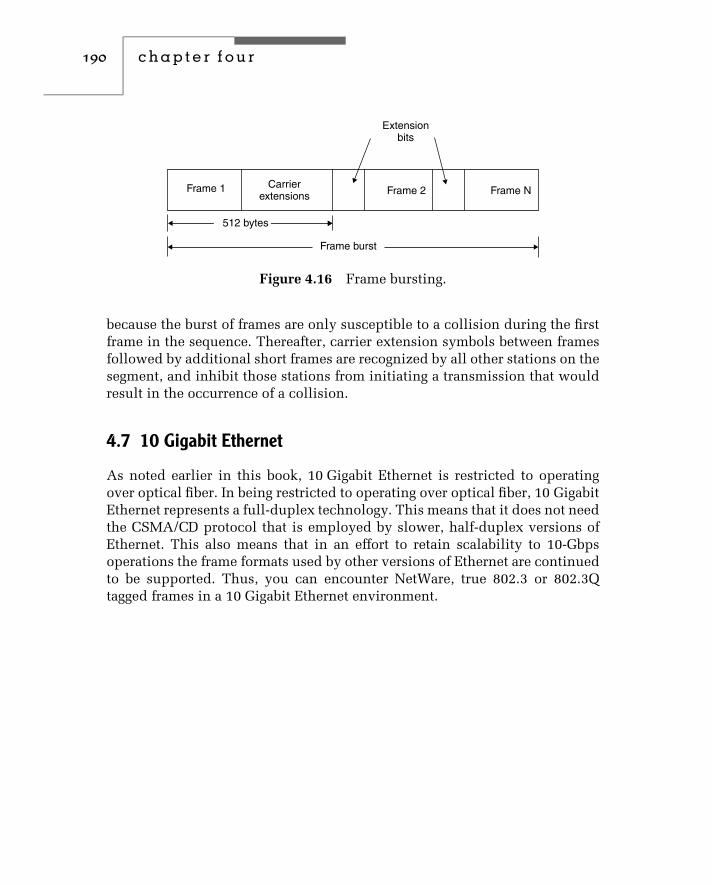
190 c h a p t e r f o u r
512 bytes
Frame burst
Frame 1 Frame 2 Frame NCarrier
extensions
Extensionbits
Figure 4.16 Frame bursting.
because the burst of frames are only susceptible to a collision during the firstframe in the sequence. Thereafter, carrier extension symbols between framesfollowed by additional short frames are recognized by all other stations on thesegment, and inhibit those stations from initiating a transmission that wouldresult in the occurrence of a collision.
4.7 10 Gigabit Ethernet
As noted earlier in this book, 10 Gigabit Ethernet is restricted to operatingover optical fiber. In being restricted to operating over optical fiber, 10 GigabitEthernet represents a full-duplex technology. This means that it does not needthe CSMA/CD protocol that is employed by slower, half-duplex versions ofEthernet. This also means that in an effort to retain scalability to 10-Gbpsoperations the frame formats used by other versions of Ethernet are continuedto be supported. Thus, you can encounter NetWare, true 802.3 or 802.3Qtagged frames in a 10 Gigabit Ethernet environment.

c h a p t e r f i v e
Networking Hardware andSoftwareUntil this chapter, our primary hardware focus was on generic productsdesigned to construct Ethernet-type networks at a single location. Althoughwe discussed the use of electrical fiber-optic repeaters, that discussion waslimited to a few network expansion examples. In addition, until now we haveessentially avoided discussing the use of bridges, routers, and gateways toextend Ethernet connectivity beyond a single network, and the role of networksoftware and how it relates to your personal computer’s operating system. Inthis chapter, we will focus our attention on those two areas.
First, we will focus our attention on the basic operation of several hardwarecomponents that are the building blocks essential to extending the connec-tivity capability of an Ethernet local area network: repeaters, bridges, routers,brouters, gateways, servers, and wiring hubs. Because Ethernet networks areno longer restricted to a wired environment, in this chapter we will alsodescribe and discuss the role of wireless Ethernet LAN adapters, access pointsand routers that include a built-in access point. Next, we will discuss the roleand operation of three major types of software required for local area networkoperations: computer operating systems, LAN operating systems, and appli-cation programs. This will be followed by a discussion of the software usedto route data from one LAN to another using different internet hardware andsoftware products. By examining hardware and software, we will obtain anappreciation for the methods used to link LANs both directly and throughwide area networks.
In this chapter and throughout this book, we will use the terms localarea network and network synonymously. We will use the term internetworkor just internet to refer to the joining of two or more local area networks.Note that we will use the latter term to refer to the combining of networksand not to the specific network called the Internet, whose first letter is
191

192 c h a p t e r f i v e
capitalized. In Chapter 7 we will examine the connection of Ethernet-basednetworks to that network, focusing our attention upon the configurationof workstations, servers, and routers to enable an Ethernet network to beconnected to the Internet.
5.1 Wired Network Hardware Components
In this section we will examine hardware products essential to the construc-tion and interconnection of local area networks that transmit informationover wired media, such as coaxial cable, twisted pair of optical fiber. Theseproducts provide us with the ability to extend the distance of local areanetwork coverage, connect local networks to distant ones, and obtain accessto centralized computational facilities.
Repeaters
A repeater is the simplest type of hardware component in terms of design,operation, and functionality. This device operates at the physical layer of theISO Open Systems Interconnection Reference Model, regenerating a signalreceived on one cable segment and then retransmitting the signal onto anothercable segment. Figure 5.1 illustrates the operation of a repeater with respectto the ISO OSI Reference Model.
Types
There are two basic types of repeaters. An electrical repeater simply receivesan electrical signal and then regenerates the signal. During the signal regenera-tion process, a new signal is formed that matches the original characteristicsof the received signal. This process is illustrated in the lower portion ofFigure 5.1. By transmitting a new signal, the repeater removes any previousdistortion and attenuation, enabling an extension in the permissible transmis-sion distance. Although several network segments can be connected by theuse of repeaters to extend the coverage of a network, there are constraints thatgovern the maximum permissible length of a LAN. For example, a 50-ohmcoaxial bus-based Ethernet supports a maximum cabling distance of 2.3 km,and that distance cannot be extended through the use of repeaters.
The second type of repeater commonly used is an electrical-optical device,such as the FOIRL repeater, the use and general operation of which were dis-cussed in Chapter 3. This type of repeater converts an electrical signal into anoptical signal for transmission and performs a reverse function when receiving

networking hardware and software 193
Application
Presentation
Session
Transport
Network
Data link
Physical Physical Physical
Application
Presentation
Session
Transport
Network
Data link
Physical
(a) OSI operation
(b) Signal regeneration process
Repeater
Figure 5.1 Repeater operation. A repeater connects two local area networksor network segments at the OSI physical layer (cable) by regenerating thesignal received on one LAN or LAN segment onto the other network ornetwork segment.
a light signal. Similar to an electrical repeater, the electrical-optical repeaterextends the distance that a signal can be carried on a local area network.
Because a repeater is restricted to operating at the OSI physical layer, it istransparent to data flow. This restricts the use of a repeater to linking identicalnetworks or network segments. For example, you could use repeaters toconnect two Ethernet or two Token-Ring network segments, but not to connectan Ethernet network to a Token-Ring network.
Utilization
Figure 5.2 illustrates the use of a repeater to connect two Ethernet bus-basedLANs, one serving the accounting department, and the other network servingthe data processing department. In this situation, all messages on one localarea network are passed to the other, regardless of their intended recipient.The use of repeaters in this manner increases the sum of the traffic on eachLAN. If this system is implemented without knowledge of the traffic flow andutilization levels on each network, performance problems may result whenseparate networks are interconnected through the use of repeaters.
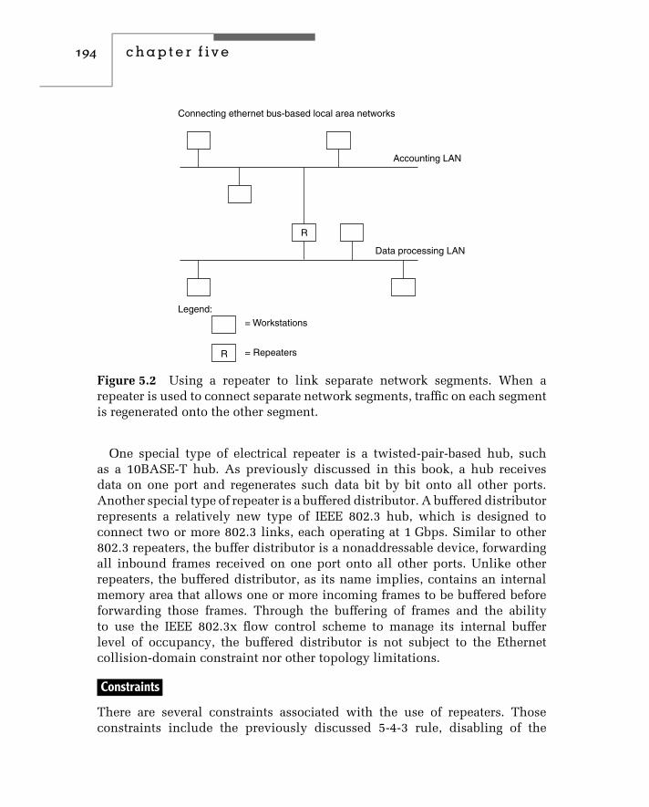
194 c h a p t e r f i v e
Accounting LAN
Data processing LAN
R
R
Connecting ethernet bus-based local area networks
Legend:= Workstations
= Repeaters
Figure 5.2 Using a repeater to link separate network segments. When arepeater is used to connect separate network segments, traffic on each segmentis regenerated onto the other segment.
One special type of electrical repeater is a twisted-pair-based hub, suchas a 10BASE-T hub. As previously discussed in this book, a hub receivesdata on one port and regenerates such data bit by bit onto all other ports.Another special type of repeater is a buffered distributor. A buffered distributorrepresents a relatively new type of IEEE 802.3 hub, which is designed toconnect two or more 802.3 links, each operating at 1 Gbps. Similar to other802.3 repeaters, the buffer distributor is a nonaddressable device, forwardingall inbound frames received on one port onto all other ports. Unlike otherrepeaters, the buffered distributor, as its name implies, contains an internalmemory area that allows one or more incoming frames to be buffered beforeforwarding those frames. Through the buffering of frames and the abilityto use the IEEE 802.3x flow control scheme to manage its internal bufferlevel of occupancy, the buffered distributor is not subject to the Ethernetcollision-domain constraint nor other topology limitations.
Constraints
There are several constraints associated with the use of repeaters. Thoseconstraints include the previously discussed 5-4-3 rule, disabling of the

networking hardware and software 195
SQE test signal to repeaters to include hub ports, and topology restrictionsassociated with the use of different types of repeaters. Concerning topology,when a metallic repeater receives a signal, it uses the received signal torecover clocking. If you recall our prior discussion of the composition ofEthernet frames, we noted that a 64-bit preamble prefixes frame data forsynchronization. As a repeater samples the preamble, it may lose a few bitsas it recovers clocking. This bit loss shrinks the gap between frames thatshould normally be 9.6 µs at 10 Mbps. In fact, according to the IEEE 802.3specifications, the interframe gap (IFG) can be as low as 6.8 µs. However,due to the gap shrinking the Ethernet specification does not permit morethan two repeaters to be located between any two communicating deviceslocated in the same collision domain. Note that this specification treats botha shared media hub and a stand-alone repeater as repeaters. Thus, while youcould use one stand-alone repeater to extend the transmission distance froma station to a hub, you could not perform a similar extension for a secondworkstation connected to the hub. This is because the hub functions as arepeater, which would result in the flow of data through three repeaters,violating the two-repeater limit within a collision domain.
You can use the information presented in this book as well as vendorspecification sheets to determine the specific constraints associated withdifferent types of repeaters. Concerning vendor specification sheets, their useis highly recommended, as the constraints associated with the use of differenttypes of repeaters can vary from one manufacturer to another.
Bridges
Unlike repeaters, which lack intelligence and are restricted to linking similarLANs and LAN segments, bridges are intelligent devices that can connectsimilar and dissimilar local area networks. To obtain an appreciation forthe functions performed by bridges, let us examine the use of this type ofnetworking product.
Operation
Figure 5.3 illustrates the operation of a bridge with respect to the OSI ReferenceModel, as well as its use to connect two separate Ethernet local area networks.Although the use of the bridge in the lower portion of Figure 5.3 looks similarto the use of a repeater previously shown in Figure 5.2, the operation of eachdevice includes a number of key differences.
When a bridge begins to operate, it examines each frame transmitted onconnected local area networks at the data link layer — a process beyond

196 c h a p t e r f i v e
OSI operation
Application
Presentation
Application
Session
Transport
Network
Data link
Physical
Presentation
Session
Transport
Network
Data link
Physical
Data link
Physical
Data link
Physical
Application example
Network A
Network B
Bridge
Legend: = Workstations
Figure 5.3 Bridge operation. A bridge connects two local area networks ornetwork segments at the data link layer.
the capability of a repeater, which operates transparent to data. By readingthe source address included in each frame, the bridge assembles a table oflocal addresses for each network. In addition to reading each source address,the bridge also reads the destination address contained in the frame. If thedestination address is not contained in the local address table that the bridgeconstructs, this fact indicates that the frame’s destination is not on the currentnetwork or network segment. In this situation, the bridge transmits the frameonto the other network or network segment. If the destination address is

networking hardware and software 197
contained in the local address table, this indicates that the frame shouldremain on the local network. In this situation, the bridge simply repeats theframe without altering its routing.
We can summarize the operation of the bridge illustrated in the lowerportion of Figure 5.3 as follows:
♦ Bridge reads all frames transmitted on network A.♦ Frames with destination address on network A are discarded by
the bridge.♦ Frames with destination address on network B are retransmitted onto
network B.♦ The above process is reversed for traffic on network B.
To illustrate the method by which bridges operate, let’s assume a three-portbridge is used to connect three Ethernet segments together, as illustrated inthe top portion of Figure 5.4. In this example, for simplicity, each port addressis denoted by a letter of the alphabet while each station address is denotedby a numeric. It should be noted that each bridge port has a MAC address asit is a participant on a LAN. Although the MAC address of bridge ports andstations have the same format and are six hex digits in length, we will use onealphabetic character for each bridge port and one numeric character for eachstation for simplicity of illustration.
The table in the lower portion of Figure 5.4 provides examples of thethree operations a bridge performs — flooding frames, forwarding frames, anddiscarding frames. In the first entry, station 1 is presumed to transmit datato station 2. Since we will assume the bridge was just powered on and hasno entries in its address-port table, it does not know which port station 2 isconnected to. Thus, it transmits the frame onto all other ports other than theport it was received on, a technique referred to as flooding. Because station 2is on the same segment as station 1, the transmission of frames onto theother segments only interferes with traffic on those segments but will notbe recognized by a station, because no station connected to port B or C hasaddress 2.
In addition to flooding packets when the location of the destination addressis not known, there are two other situations where bridge flooding can occur.Those situations include the receipt of a multicast or broadcast frame at oneport on a bridge, which results in such frames being transmitted onto all portsother than the port they are received on. Returning to the example shown inFigure 5.4, when the frame from station 1 is flooded by the bridge, it entersthe source address and port that the frame was received on into its address-port table. Hence the entry ‘‘1, A.’’ When the frame reaches station 2, we will

198 c h a p t e r f i v e
A
C
B
2
5 6 7
3 4
1
Bridge
Data Transfer Requirement Bridge Operation Address-Port Table
1 Transmits to 2 Frame flooded 1,A
1,A2,A
2,A
2,A3,B
2,A5,C
5,C
5,C
6,C
6,C
1,A
1,A
1,A
2 Transmits to 1 Frame discarded
Frame forwarded
Frame flooded
Frame forwarded
5 Transmits to 1
6 Transmits to 3
3 Transmits to 6
Figure 5.4 Bridges are self-learning networking devices that automaticallyconstruct address-port table entries used to route data between networksegments.
assume 2 transmits a response to 1. As the frame propagates down the segmentand is read by bridge port A, it notes that address 1 is on port A. Thus, there isno need for the bridge to forward the frame and it simply discards it. However,the bridge notes address 2 is on port A and updates its address-port table.
For the third example, it was assumed that station 5 transmits to station 1.Because the address-port table holds the relationship of address 1 with port A,the bridge forwards the frame onto port A and updates its address-port table.Next, when station 6 transmits to station 3 and the bridge checks its address-port table, it finds no entry for address 3, resulting in the bridge floodingthe frame onto ports B and C. Then the bridge notes that station 6 is not in

networking hardware and software 199
its address-port table and updates that table. In the last example, station 3transmits a response to station 6. Because an entry for station 6 was just madein the address-port table, the bridge forwards the frame onto port C.
In addition to associating addresses with ports, a bridge also time stampseach entry and updates the time stamp when an address is referenced. Asstorage is used up and the bridge needs to purge old entries to make roomfor new entries, it will purge the oldest entries based upon the use of thetime stamp.
The previously described method of bridging operation is referred to astransparent bridging. Refer to Chapter 6 for detailed information concerningdifferent methods of bridge operations.
Filtering and Forwarding The process of examining each frame is knownas filtering. The filtering rate of a bridge is directly related to its level ofperformance. That is, the higher the filtering rate of a bridge, the lower theprobability it will become a bottleneck to network performance. A secondperformance measurement associated with bridges is their forwarding rate.The forwarding rate is expressed in frames per second and denotes themaximum capability of a bridge to transmit traffic from one network to another.In Chapter 6, we will expand our examination of bridges to determine theirmaximum filtering and forwarding rates when used on Ethernet networks.
Types
There are two general types of bridges: transparent and translating. Each typeof bridge can be obtained as a local or remote device; a remote device includesa wide area network interface and the ability to convert frames into a WANtransmission protocol.
Transparent Bridge A transparent bridge provides a connection betweentwo local area networks that employ the same data link protocol. Thus, thebridge shown in the lower portion of Figure 5.3 and the bridge shown inthe upper portion of Figure 5.4 are both examples of transparent bridges. Atthe physical layer, some transparent bridges have multiple ports that supportdifferent media. Thus, a transparent bridge does not have to be transparent atthe physical level, although the majority of such bridges are.
Although a transparent bridge provides a high level of performance for asmall number of network interconnections, its level of performance decreasesas the number of interconnected networks increases. The rationale for thisloss in performance is based on the method used by transparent bridges to

200 c h a p t e r f i v e
develop a route between LANs. Refer to Chapter 6 for specific informationconcerning bridge routing and performance issues.
Translating Bridge A translating bridge provides a connection capabilitybetween two local area networks that employ different protocols at the datalink layer. Because networks using different data link layer protocols normallyuse different media, a translating bridge also provides support for differentphysical layer connections.
Figure 5.5 illustrates the use of a translating bridge to interconnect a Token-Ring and an Ethernet local area network. In this example, the bridge functionsas an Ethernet node on the Ethernet and as a Token-Ring node on theToken-Ring. When a frame from one network has a destination on the othernetwork, the bridge will perform a series of operations, including frameand transmission rate conversion. For example, consider an Ethernet framedestined to the Token-Ring network. The bridge will strip the frame’s preambleand FCS, then it will convert the frame into a Token-Ring frame format. Oncethe bridge receives a free token, the new frame will be transmitted onto theToken-Ring; however, the transmission rate will be at the Token-Ring networkrate and not at the Ethernet rate. For frames going from the Token-Ring to theEthernet, the process is reversed.
Bridge
Token-ring
Ethernet LAN
Legend: = Workstations
Figure 5.5 Translating bridge oper-ation. A translating bridge connectslocal area networks that employ differ-ent protocols at the data link layer. Inthis example, the translating bridge isused to connect an Ethernet local areanetwork to a Token-Ring network.

networking hardware and software 201
One of the problems associated with the use of a translating bridge is theconversion of frames from their format on one network to the format requiredfor use on another network. As indicated in Chapter 2, the information fieldof an Ethernet frame can vary from 64 to 1500 bytes. In comparison, a Token-Ring can have a maximum information field size of 4500 bytes when the ringoperates at 4 Mbps, or 18,000 bytes when the ring operates at 16 Mbps. If astation on a Token-Ring network has a frame with an information field thatexceeds 1500 bytes in length, the bridging of that frame onto an Ethernetnetwork cannot occur. This is because there is no provision within eitherlayer 2 protocol to inform a station that a frame flowing from one network toanother was fragmented and requires reassembly. Using a bridge effectivelyin this situation requires that software on each workstation on each networkbe configured to use the smallest maximum frame size of any interconnectednetwork. In this example, Token-Ring workstations would not be allowed totransmit information fields greater than 1500 bytes.
Features
The functionality of a bridge is based on the features incorporated into thisdevice. Following is a list of the 11 major bridge features that define both thefunctionality and the performance level of a bridge.
♦ Filtering and forwarding rate♦ Selective forwarding capability♦ Multiple port support♦ Wide area network interface support♦ Local area network interface support♦ Transparent operation at the data link layer♦ Translating operation to link dissimilar networks♦ Encapsulation operation to support wide area network use♦ Stand-alone and adapter-based fabrication♦ Self-learning (transparent) routing♦ Source routing
Filtering and Forwarding The filtering and forwarding rates indicate theability of the bridge to accept, examine, and regenerate frames on the samenetwork (filtering) and transfer frames onto a different network (forwarding).Higher filtering and forwarding rates indicate better bridge performance.
Selective Forwarding Some bridges have a selective forwarding capability.Bridges with this feature can be configured to forward frames selectively, based

202 c h a p t e r f i v e
on predefined source and destination addresses. With a selective forwardingcapability, you can develop predefined routes for frames to take when flowingbetween networks, and enable or inhibit the transfer of information betweenpredefined workstations.
Figure 5.6 illustrates the use of the selective forwarding capability of twobridges to provide two independent routes for data transfer between anEthernet and a Token-Ring network. In this example, you might enable allworkstations with source address 1 or 2 to have data destined to the Token-Ring flow over bridge 1, while workstations with a source address of 3 or 4are configured to use bridge 2. Although the bridges illustrated in Figure 5.5appear to form a closed loop, in effect the previously described method ofselective forwarding results in a single logical path for each station on theEthernet. This ensures there are no closed loops — a condition that wouldviolate the spanning tree bridging algorithm supported by Ethernet bridges.The operation of that algorithm is described in Chapter 6.
Multiple Port Support The multiple port support capability of a bridge isrelated to its local and wide area network media interface support. Some
Token-ring
Legend: = Workstations
2
1 3
B1 B1
4
Ethernet
Figure 5.6 Using bridge selective forwarding capability. Using the selectiveforwarding capability of bridges enables the data flow between networks to bedistributed based upon source or destination addresses.

networking hardware and software 203
bridges support additional ports beyond the two that make up a basic bridge.Doing so enables a bridge to provide connectivity between three or more localarea networks.
Figure 5.7 illustrates one potential use of a multiple port bridge to link anEthernet network to two Token-Ring networks.
Local and Wide Area Interface Support Local area media interfaces sup-ported by bridges can include thin and thick Ethernet coaxial cable, shieldedand unshielded twisted-pair metallic, cable, and different types of fiber opticcable. Wide area network interfaces are incorporated into remote bridges thatare designed to provide an internetworking capability between two or moregeographically dispersed LANs linked by a WAN. Common WAN media inter-faces can include RS-232 for data rates at or below 19.2 Kbps, ITU X.21 forpacket network access at data rates up to 128 Kbps, ITU V.35 for data rates upto approximately 6 Mbps, and a T1/E1 interface for operations at 1.544 Mbpsand 2.048 Mbps, respectively.
Transparent Operation Although bridges are thought of as transparent todata, this is not always true. For interconnecting different networks located in
Legend: = Workstations
Token-ringToken-ring
Multiportbridge
Figure 5.7 Using a multiport bridge. With a multiport bridge, you can inter-connect three or more local area networks.

204 c h a p t e r f i v e
the same geographical area, bridges are normally transparent to data. However,some remote bridges use data compression algorithms to reduce the quantityof data transmitted between bridges connected via a wide area network. Suchcompression performing bridges are not transparent to data, although theyrestore data to its original form.
Frame Translation For interconnecting different types of local area net-works, bridges must perform a translation of frames. For example, an Ethernetframe must be changed into a Token-Ring frame when the frame is routedfrom an Ethernet to a Token-Ring network. As previously mentioned, becauseframes cannot be fragmented at the data link layer, you must set the worksta-tions on the Token-Ring network to the smallest maximum information fieldof an Ethernet frame, 1500 bytes.
When data is transferred between colocated local area networks, the frameformat on one network is suitable for transfer onto the other network; it ismodified for transfer when the media access control layers differ. When abridge is used to connect two local area networks via a wide area networkfacility, a WAN protocol is employed to control data transfer. The widearea network protocol is better suited for transmission over the WAN, asit is standardized to incorporate error detection and correction, enable alarge number of unacknowledged WAN frames to exist to speed informationtransfer, and support full-duplex data transfers. Examples of such wide areanetwork protocols include IBM’s SDLC, and the ITU’s HDLC and X.25.
Frame Encapsulation Figure 5.8 illustrates the operation of a pair of remotebridges connecting two local area networks via a wide area network. Fortransmission from network A to network B, user data from a network A stationis first converted into logical link control and media access control frames. Thebridge then encapsulates one or more LAN frames into the bridging protocolframe used for communications over the wide area network. Because the localarea network frame is wrapped in another protocol, we say the LAN frameis tunneled within the WAN protocol. At the opposite end of the wide areanetwork, the distant remote bridge performs a reverse operation, removing theWAN protocol header and trailer from each frame.
Fabrication Some bridges are manufactured as stand-alone products. Suchdevices are called plug and play, because you simply connect the bridge portsto the media and turn them on. Other bridges are manufactured as adaptercards for insertion into the system unit of a personal computer, workstation,or reduced instruction set computer (RISC). Through the use of software

networking hardware and software 205
User data
User dataLLC-H
User dataLLC-HMAC-H
MAC-H
LLC-T
User dataLLC-H LLC-TLink-H Link-T
Frame compositionLocation
1, 9
2, 8
3, 4, 6, 7
5
StationUserLLCMAC
Physical
StationUserLLCMAC
PhysicalPhysicalPhysical PhysicalMAC
PhysicalLinkMAC Link
123 4 6
5
987
Bridge Bridge
WANFacility
LAN A LAN B
Figure 5.8 Remote bridge operation. A remote bridge wraps the logical linkcontrol (LLC) and media access control (MAC) frames in another protocol fortransmission over a wide area network.
developed in conjunction with hardware, you may obtain more flexibilitywith this type of bridge than with a stand-alone device whose software isfixed in ROM.
Routing Method The routing capability of a bridge governs its capability tointerconnect local area networks and its level of performance. As previouslyexamined through the use of Figure 5.4, a transparent bridge automaticallydevelops routing tables. Thus, this device is known as a self-learning bridgeand represents the most elementary type of bridge routing. In the IBM Token-Ring frame, there is an optional routing field that can be used to developrouting information for frames routed through a series of bridges — a techniquereferred to as source routing. Refer to Chapter 6 for an in-depth discussion ofbridge routing methods, as well as translating operations that enable a bridgeto connect IEEE 802.3 and 802.5 networks.
Routers
A router is a device that operates at the network layer of the ISO OSIReference Model, as illustrated in Figure 5.9. What this means is that a routerexamines network addresses and makes decisions about whether data on alocal area network should remain on the network or should be transmitted

206 c h a p t e r f i v e
Application
Presentation
Session
Transport
Network
Data link
Physical
Application
Presentation
Session
Transport
Network
Data link
Physical
Network
Data link
Physical
Network
Data link
Physical
Figure 5.9 Router operation. A router operates at the network layer of theISO OSI Reference Model. This enables a router to provide network layerservices, such as flow control and frame fragmentation.
to a different network. Although this level of operation may appear to beinsignificant compared with that of a bridge operating at the data link layer,there is actually a considerable difference in the routing capability of bridgesand routers.
Operation
A bridge uses 48-bit MAC addresses it associates with ports as a mechanismto determine whether a frame received on one port is ignored, forwarded ontoanother port, or flooded onto all ports other than the port it was received on.At the data link layer there is no mechanism to distinguish one network fromanother. Thus, the delivery of frames between networks requires bridges tolearn MAC addresses and base their forwarding decisions on such addresses.Although this is an acceptable technique for linking a few networks together,as the number of networks increase and the number of workstations on inter-connected networks increase, bridges would spend a considerable amount oftime purging old entries and flooding frames, causing unacceptable perfor-mance problems. This resulted in the development of routers that prevent theflooding of frames between networks and operate by using network addresses.
To understand the concept behind routing, consider Figure 5.10, whichillustrates two networks connected by a pair of routers. In this example,assume addresses A, B, C, and D represent MAC addresses of workstations,and E and F represent the MAC address of each router connected to each

networking hardware and software 207
E
Router1
A B
Network 10
F
Router2
C D
Network 10
Figure 5.10 Routing between two networks. When a workstation on onenetwork transmits data to a device on another network, an application programprovides the destination network address, which is used by routers as a basisfor their routing decisions.
network. Assuming workstation A has data to transmit to workstation C, anapplication program executing on workstation A assigns network 20 as thedestination network address in a packet it prepares at the network layer. Thatpacket is transported via one or more MAC frames to MAC address E, whichis the data link address of the network adapter card installed in router 1.
In actuality, each device on a network can have a unique network address,with a portion of the address denoting the network and the remainder of theaddress denoting each host or router interface. This enables the applicationprogram on workstation A to transmit a packet destined to workstation C torouter 1, with the data link layer passing the packet to MAC address E as aframe or sequence of frames. The router receives the frame or sequence offrames explicitly addressed to it and notes that the packet has the destinationaddress for network 20. The router then searches its routing tables anddetermines that it should relay the packet to router 2. When the packet isreceived at router 2, it recognizes the fact that network 20 is connected to therouter via its connection to the LAN by an adapter card using MAC address F.Thus, the router will transport the packet to its destination using one or moreframes at the data link layer with a MAC source address of F.
The preceding description represents a simplified description of the routingprocess. A more detailed description will be presented later in this book afterwe investigate the TCP/IP protocol suite. We will examine the TCP/IP protocolsuite in the second section in this chapter when we turn our attention to net-working software and focus our attention upon router operations in Chapter 7.
The ability to operate at the network layer enables a router to extendnetworking across multiple data links in an orderly and predefined manner.This means that a router can determine the best path through a series of datalinks from a source network to a destination network. To accomplish this,

208 c h a p t e r f i v e
the router operates under a network protocol, such as the Internet Protocol(IP), Digital Equipment Corporation’s DECnet Phase V, or Novell’s IPX. Thisnetworking protocol must operate on both the source and destination networkwhen protocol-dependent routers are used. If you use protocol-independentrouters, you can interconnect networks using different protocols. The protocol-independent router can be considered a sophisticated transparent bridge. Itsoperation and utilization are described in detail in Chapter 7.
In comparison, because a bridge operates at the data link layer, it canalways be used to transfer information between networks operating underdifferent network protocols. This makes a bridge more efficient for linkingnetworks that only have one or a few paths, while a router is more efficientfor interconnecting multiple network links via multiple paths.
Network Address Utilization Unlike a bridge, which must monitor allframes at the media access control layer, a router is specifically addressedat the network layer. This means that a router has to examine only framesexplicitly addressed to that device. In communications terminology, themonitoring of all frames is referred to as a promiscuous mode of operation,while the selective examination of frames is referred to as a nonpromiscuousmode of operation.
Another difference between the operation of bridges and routers is thestructure of the addresses on which they operate. Bridges operate at the datalink layer, which means that they typically examine physical addresses thatare contained in ROM on adapter cards and used in the generation of frames.In comparison, routers operate at the network layer, where addresses arenormally assigned by a network administrator to a group of stations having acommon characteristic, such as being connected on an Ethernet in one areaof a building. This type of address is known as a logical address, and can beassigned and modified by the network administrator.
Table Operation Like bridges, routers make forwarding decisions usingtables. However, unlike a bridge, which may employ a simple table look-upprocedure to determine if a destination address is on a particular network,a router may employ much more sophisticated forwarding decision criteria.For example, a router may be configured to analyze several paths usingan algorithm and dynamically select a path based upon the results of thealgorithm. Routing algorithms and protocols are discussed in Chapter 7.
Advantages of Use The use of routers provides a number of significantadvantages over the use of bridges. To illustrate these advantages, we will
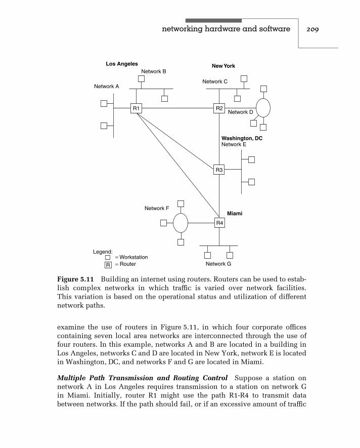
networking hardware and software 209
R
Legend:= Workstation= Router
Network F
Network G
R4
Miami
R3
Washington, DCNetwork E
Network D
Network C
Network B
Network A
New York
R2R1
Los Angeles
Figure 5.11 Building an internet using routers. Routers can be used to estab-lish complex networks in which traffic is varied over network facilities.This variation is based on the operational status and utilization of differentnetwork paths.
examine the use of routers in Figure 5.11, in which four corporate officescontaining seven local area networks are interconnected through the use offour routers. In this example, networks A and B are located in a building inLos Angeles, networks C and D are located in New York, network E is locatedin Washington, DC, and networks F and G are located in Miami.
Multiple Path Transmission and Routing Control Suppose a station onnetwork A in Los Angeles requires transmission to a station on network Gin Miami. Initially, router R1 might use the path R1-R4 to transmit databetween networks. If the path should fail, or if an excessive amount of traffic

210 c h a p t e r f i v e
flows between Los Angeles and Miami using that path, router R1 can seek toestablish other paths, such as R1-R3-R4 or even R1-R2-R3-R4. In fact, manyrouters will consider each packet as a separate entity, routing the packet to itsdestination over the best available path at the time of transmission. Althoughthis could conceivably result in packets arriving at R4 out of sequence, routershave the capability to resequence packets into their original order beforepassing data onto the destination network.
Flow Control As data flows through multiple paths toward its destination, alink can become congested. For example, data from stations on network C andnetwork E routed to network G might build up to the point where the pathR3-R4 becomes congested. To eliminate the possibility of packet loss, routerswill use flow control. That is, they will inhibit transmission onto a link andnotify other routers to inhibit data flow until there is an available level ofbandwidth for traffic.
Frame Fragmentation As previously mentioned, bridges cannot break aframe into a series of frames when transmission occurs between networkswith different frame sizes. This situation requires workstations to be con-figured to use the smallest maximum frame size of any of the networksto be connected together. In comparison, most network protocols sup-ported by routers include a provision for fragmentation and reassemblyof packets.
The higher level of functionality of routers over bridges is not withouta price. That price is in terms of packet processing, software complexity,and cost. Since routers provide a more complex series of functions thanbridges, their ability to process packets is typically one-half to two-thirdsof the processing capability of bridges. In addition, the development timerequired to program a more complex series of functions adds to the cost ofrouters. Thus, routers are generally more expensive than bridges. Table 5.1summarizes the major differences between bridges and routers in terms oftheir operation, functionality, complexity, and cost.
Brouters
A brouter is a hybrid device, representing a combination of bridging androuting capabilities. Although brouters are no longer marketed using thisterm, their functionality lives on in modern routers that include a bridgingcapability.

networking hardware and software 211
TABLE 5.1 Bridge/Router Comparison
Characteristic Bridge Router
Routing based upon an algorithmor protocol
Normally no Yes
Protocol transparency Yes Only protocol-independentrouter
Uses network addresses No Yes
Promiscuous mode of operation Yes No
Forwarding decision Elementary Can be complex
Multiple path transmission Limited High
Routing control Limited High
Flow control No Yes
Frame fragmentation No Yes
Packet processing rate High Moderate
Cost Less expensive More expensive
Operation
When a brouter receives a frame, it examines that frame to determine whetherit is destined for another local area network. If it is, the brouter then checksthe protocol of the frame to determine whether it is supported at the networklayer supported by the router function. If the frame’s protocol is supported,the brouter will route the frame as if it were a router. However, if the brouterdoes not support the protocol, it will instead bridge the frame using layer 2information.
In comparison to routers, brouters provide an additional level of connectiv-ity between networks, although that connectivity takes place at a lower levelin the OSI Reference Model hierarchy. This is because a router would simplyignore a frame for which it does not support the network protocol, while abrouter would bridge the frame.
Utilization
The key advantage of using a brouter is the ability of this device to bothbridge and route data. Its ability to perform this dual function enables abrouter to replace the use of separate bridges and routers in some networking

212 c h a p t e r f i v e
applications. For example, consider the use of a separate bridge and routerin the top portion of Figure 5.12. In this example, the bridge provides aninterconnection capability between two neighboring networks, while therouter provides an interconnection capability to distant networks. By replacingthe separate bridge and router with a brouter, you can obtain the same levelof functionality, as illustrated in the lower portion of Figure 5.12. Of course,you want to ensure that the filtering and forwarding rates of the brouter aresufficient to be used in the manner illustrated. Otherwise, the replacementof separate bridges and routers by brouters may introduce delays that affectnetwork performance. As previously noted, many modern routers includea built-in bridging capability and, as such, can be considered to representa brouter. Refer to Chapters 6 and 7 for information concerning the processingrequirements of bridges and routers.
B
R
BR
Using a brouter
Using a separate bridge and router
To other networks
To other networks
Figure 5.12 Replacing a separate bridge and router with a brouter.

networking hardware and software 213
Gateway
The well-known phrase ‘‘one person’s passion is another’s poison’’ can, inmany ways, apply to gateways. The term gateway was originally coined torefer to a device providing a communications path between two local areanetworks, or between a LAN and a mainframe computer, from the physicallayer through the application layer. When applied to a device interconnectingnetworks, the term gateway was originally used and is still commonly used toreference a router. In fact, many programs used to configure workstation andserver network operations request the entry of the gateway network address,even though it is more appropriate today to use the term router.
Figure 5.13 illustrates the operation of a gateway with respect to the ISOOSI Reference Model. Unfortunately, the term gateway has been used looselyto describe a range of products, ranging from bridges and routers that inter-connect two or more local area networks to protocol converters that provideasynchronous dial-up access into an IBM SNA network. Thus, a definition ofthe term is warranted.
Definition
In this book, we will use the term gateway, unless otherwise noted, todescribe a product that performs protocol conversion through all seven layersof the ISO OSI Reference Model. As such, a gateway performs all of thefunctions of a router, as well as any protocol conversions required throughthe application layer.
Application
Presentation
Session
Transport
Network
Data link
Physical
Application
Presentation
Session
Transport
Network
Data link
Physical
Application
Presentation
Session
Transport
Network
Data link
Physical
Application
Presentation
Session
Transport
Network
Data link
Physical
Figure 5.13 Gateway operation. A gateway operates at all seven layers of theISO OSI Reference Model.

214 c h a p t e r f i v e
One of the most common types of gateways is an electronic mail (e-mail)gateway, which converts documents from one e-mail format to another. Forexample, an internal corporate network might be operating Lotus DevelopmentCorporation’s CC:MAIL. If they require connectivity with the Internet, thegateway must convert internal CC:MAIL documents so that they can betransported via the Simple Mail Transport Protocol (SMTP), which is a TCP/IPelectronic mail application. Similarly, SMTP mail delivered via the Internet tothe organization’s gateway must be converted by the gateway into the formatused by CC:MAIL. A second type of popular gateway enables workstationson a network to communicate with a mainframe as if the workstation wasa specific type of terminal device. This type of gateway also operates at allseven layers of the ISO Reference Model.
Operation
Gateways are protocol-specific in function, typically used to provide access toa mainframe computer. Some vendors manufacture multiprotocol gateways.Such products are normally manufactured as adapter cards, containing sep-arate processors that are installed in the system unit of a personal computeror in a specially designed vendor hardware platform. When used in conjunc-tion with appropriate vendor software, this type of gateway is actually anN-in-1 gateway, where N is the number of protocol conversions and separateconnections the gateway can perform.
Figure 5.14 shows a multiprotocol gateway used to link LAN stations toan IBM mainframe via an SDLC link and an X.25 connection to a packetswitching network. Once connected to the packet switching network, LANtraffic may be further converted by gateway facilities built into that network,or traffic may be routed to a packet network node and transmitted from thatnode to its final destination in its X.25 packet format.
Gateways are primarily designed and used for LAN-WAN connections andnot for inter-LAN communications. Because they perform more sophisticatedfunctions than routers, they are slower in providing network throughput. Inaddition, because the configuration of a gateway requires the consideration ofa large number of protocol options, a gateway installation is considerably moredifficult than the setup of a router. Refer to Chapter 8 for specific informationconcerning the operation and utilization of gateways.
File Servers
The file server is the central repository of information upon which a localarea network is normally constructed. The file server is normally a personal

networking hardware and software 215
Legend:= Workstation= Adapter card
Modem
Modem
Gateway
A A
A
SDLCIBMmainframe
PacketNetwork
Figure 5.14 Multiprotocol gateway operation. A multiprotocol gateway canbe used to provide local area network stations access to different computa-tional facilities, either directly or through the use of a packet network.
computer or workstation that has a very powerful microprocessor, such asan Intel Pentium, Digital Alpha, or a RISC chip, and a large amount of fast-access on-line storage. The on-line storage is used to hold the local areanetwork operating system and the application programs that other stationson the network may use. Several software vendors have split applicationprograms, enabling portions of a program to be run on a network station,while other portions, such as the updating of a database, occur on the server.This technique is known as client–server processing.
In comparison, the general term client/server operations references theaccess of one computer by another on a network. The computer being accessed,while normally considered to represent a file server, can also be a mainframeor minicomputer. For either situation, the client uses a network to accessone or more features of the server. Those features can range in scope from aspreadsheet program stored on a file server to a database query program on amainframe that provides access to billions of records.
Connectivity Functions
As the heart of a local area network, the server supports every network appli-cation. It is therefore in an ideal position to perform connectivity functions.Some servers are designed to function as asynchronous gateways, providingaccess to one or more modems that individual network stations can access

216 c h a p t e r f i v e
for communications via the switched telephone network. Here, software onthe server considers the group of modems as a pool for access purposes.Hence, the term modem pooling is used to refer to a server used to providethis service.
Other servers contain software and hardware to provide access to mainframecomputers via a specific protocol, such as SDLC, X.25, or TCP/IP. Dependingon the capabilities of the network operating system used on the server, theserver may support server-to-server communications on an intra- and inter-LAN basis. When supporting intra-LAN server-to-server communications, youcan assign network users to a specific default server for an initial networklog-on, distributing the use of servers so that no one server becomes overused.Then, the network operating system would support the transfer of informationbetween servers, such as an electronic mail message created by a network userassigned to one server, who addresses the message to another employeeassigned to a different server. If your network operating system supportsinter-LAN server-to-server communications, the server in effect functions as aremote bridge.
Types of Servers
The first type of server developed for use with local area networks primarilysupported file and printer sharing. Thus, although referred to as a file server,the server also permitted a few printers to be connected to the computer asnetwork-accessible devices. As the concept of local area networking gainedacceptance, servers were developed to perform specific functions. Today,popular types of servers include application servers, communications servers,print servers, and remote access servers (RASs). Figure 5.15 illustrates anEthernet network that contains four distinct types of servers.
The RAS can be considered to represent a hybrid device that consists ofa modem pool and router. This type of server permits the support of serialcommunications in the form of analog modems, digital ISDN calls, and theconnection of a T1 circuit that contains 24 individual connections groupedtogether on a common circuit. Incoming communications are prompted foraccess validation, typically in the form of a user ID and password, to gainaccess from the RAS onto the network. Once connected to the network,they then obtain access privileges commensurate with the network accountthey have.
Although a communications server also provides connectivity betweena network and a serial communications facility, there are some distinctdifferences between this server and an RAS. First, a communications server is

networking hardware and software 217
MM MM
Legend: = Workstations
Switched network
Applicationserver
Remoteaccessserver
Communi-cationsserver
Printer Printer
Printserver
Figure 5.15 Servers can be acquired to perform specific functions.
primarily used for outbound traffic from network users, although if should beNoted that it supports full-duplex communications. Thus, it may not supportinbound traffic, and if it does, it probably just places the traffic onto the networkwithout checking the validity of the user. Secondly, most communicationsservers function as replacements for users having individual modems. Thus,another popular name for a limited capability communications server is amodem pooler.
Location Considerations
Figure 5.16 illustrates a file server used both in its traditional role as arepository for application programs and for modem pooling and gatewayoperations. The transmission of information between workstations and serversfar exceeds transmission between workstations. The location of file serverson an Ethernet local area network is therefore critical for ensuring thatnetwork performance remains at an acceptable level. In the example shownin Figure 5.16, the server is located at a point on an Ethernet bus-based localarea network in which the transmission distance between each workstationand the server is maximized. This location results in the greatest propagationdelay for the transmission of data between each workstation and the server.

218 c h a p t e r f i v e
Legend:= Workstation
Server
Figure 5.16 Server placement. Thelocation of a server on a networkis critical for ensuring network per-formance. In this example, becauseeach workstation requires access tothe server, its location requires thegreatest transmission distance bet-ween individual workstations andthe server. This, therefore, is proba-bly a poor server location.
This is probably a poor location with respect to network performance if eachworkstation requires a similar level of access to the server.
The reason for this representing a poor placement is the fact that the longerthe distance between two network devices on a CSMA/CD access protocolnetwork, the greater the probability that one station will listen to the networkand not hear a signal while another has just began transmitting. This, in turn,results in an increased number of collisions that adversely affects networkperformance. Because collisions result in the occurrence of a random back-offtime interval during which no data can be transferred on the network, theproper location of a server can increase network transmission efficiency.
Wire Hubs
As mentioned in Chapter 3, 10BASE-T, 100BASE-T, and the half-duplexversion of Gigabit Ethernet use wiring concentrators, or hubs. Hubs aretypically located in telephone wiring closets, with stations cabled to the hubin the form of a star. Hubs are then connected to one another to form a bus.Only if the closest workstations to the server require a disproportionate levelof server access, in comparison to other workstations, is the server locationshown in Figure 5.16 correct. If each workstation has an equal level of serveraccess, the server should be relocated to the middle of the network. Thismove would minimize propagation delays between the workstations and theserver — which, in turn, would minimize the probability of collisions.
Advantages
Ethernet hubs employ standard wiring between stations and the hub in theform of twisted-pair cable. Because workstations are connected to a single

networking hardware and software 219
point, administration of a hub-based network is normally simple and econom-ical, because a central point allows network configuration and reconfiguration,monitoring, and management. Due to the value of hubs in local area network-ing, several vendors introduced products commonly referred to as intelligenthubs. This product provides users with the ability to build local area net-works, ranging in scope from a single LAN with a small number of nodesto mixed-protocol LANs with several thousand nodes that can be monitored,modified, and analyzed from a single point.
Intelligent Hubs
An intelligent hub represents an advance in functionality and capability overconventional wire hubs. The intelligent hub includes its own microprocessorand memory, which not only provide a network management capability, but,in addition, may provide the ability to interconnect separate networks throughintegrated bridges and routers.
Most intelligent hubs include a multibus backplane, which enables bridgesand routers to access and route data originating over multiple types of media.When operating in this manner, the intelligent hub can be viewed as a PBX,providing connectivity between any station on any network connected throughthe hub, while providing a centralized management and control capability.
Through the use of an intelligent hub, the administrator can enable or disablenetwork ports from a network management workstation, segment a networkto balance traffic better and improve performance, and facilitate troubleshoot-ing and maintenance operations. As networks became more sophisticated,intelligent hubs evolved to facilitate their operation and management. Withthe ability of some intelligent hubs to bring together various media flavorsof different local area networks, this device also provides a mechanism forthe integration of prior piece-by-piece planning, or for the correction ofa plan gone astray. Thus, the use of an intelligent hub may provide youwith an umbrella mechanism to bring together separate networks and mediapreviously installed in a building.
Switching Hubs
Improvements in the design of intelligent hubs to include faster backplanes,port memory buffers, and one or more mechanisms to control the flowof information resulted in the development of a series of Ethernet hardwareproducts. Collectively referred to as switching hubs or LAN switches, products

220 c h a p t e r f i v e
in this broad category of equipment examine the destination address of eachframe as a decision criteria for invoking a switching operation.
A switching hub can be considered to represent a sophisticated bridge thathas the ability to support multiple bridging operations at the same time. Thisis illustrated in Figure 5.17, which shows a 6-port switch with workstationsconnected to ports 3 and 4 having frames transported to servers connected toports 5 and 6. If each port operates at 10 Mbps then the two cross-connectionsprovide 20 Mbps of bandwidth. In comparison, a conventional shared media10BASE-T network only permits one frame at a time to be on the network,limiting bandwidth to 10 Mbps.
Some switching hubs are limited to working with individual workstationsconnected to each port, while other switching hubs are designed to switchframes from all workstations on a segment connected to the hub. The firsttype of switching is referred to as port switching, while the second typeof switching is referred to as segment-based switching. The developmentof 100-Mbps high-speed Ethernet technology resulted in several vendorsintroducing multiple-speed switching hubs during 1994 and 1995, whichcould be used to significantly improve the performance of many types ofnetworks. This improvement primarily resulted from the connection of 100-Mbps ports to file servers, while 10-Mbps ports are connected to 10BASE-Tworkstations and conventional hubs. Similarly, the first series of Gigabit Eth-ernet switches, which reached the market during 1997, have 100-Mbps and1-Gbps ports, with the 100-Mbps ports used to support Fast Ethernet con-nections. Continuing the switching evolution, during 2001 several switches
= WorkstationsLegend:
Server Server
5 6
4321
Switchinghub
Figure 5.17 A switching hub supports multiplesimultaneous cross-connection operations, whichenhance available network bandwidth.

networking hardware and software 221
were introduced that included one or two 10 Gigabit Ethernet ports, whilethe remainder of the switch was limited to supporting Gigabit transmission.Another technology incorporated into switching hubs is a full-duplex oper-ating capability, permitting the simultaneous transmission and reception ofdata on a connection. Although many switching hub manufacturers denotethis capability for a 10BASE-T connection; for example, as a 20-Mbps Eth-ernet port, in reality you obtain a 20-Mbps transmission rate only whena device is simultaneously transmitting and receiving information. Becausefile servers benefit more than workstations from a full-duplex transmissioncapability, most network designers connect their file servers to the full-duplex port on a switching hub that supports this capability, and use theconventional ports for connections to workstations. Readers are referred toChapter 6 for an in-depth examination of the operation and utilization ofswitching hubs.
5.2 Wireless Network Hardware Components
Because this chapter is focused upon network hardware and software, thisauthor would be remiss if he did not review wireless Ethernet LAN com-ponents. However, prior to doing so, a brief description of the two types ofnetworking infrastructure supported via wireless LANs is in order.
Network Topologies
The ability to communicate via the use of the air requires computers to have awireless LAN network adapter card. That network adapter card functions sim-ilarly to a wired LAN adapter card, taking application data and forming frames.However, those frames are created to flow over the air and the physical layerof the wireless LAN adapter card supports radio frequency communicationsinstead of communications over a metallic or fiber-optic media.
There are two types of network topologies supported by wireless LANs.Those topologies are referred to as ad hoc or simultaneous and infras-tructure. An ad hoc network is formed when two clients with wirelessLAN network adapters come into close proximity with one another. Thesecond type of wireless LAN topology is referred to as an infrastructure.Under this networking topology, wireless LAN clients communicate with oneanother, as well as with their wired relatives, through an access point.Thus, in order to obtain an appreciation of the infrastructure topology,the reader requires an understanding of the manner by which an accesspoint operates.

222 c h a p t e r f i v e
Access Point
An access point can be considered to represent a two-port bridge. However,instead of each port being connected to a wired LAN, one port is connectedto an antenna.
Figure 5.18 illustrates the use of an access point to provide a wireless infras-tructure communications topology. Note that in this example two wirelessclients with wireless LAN adapter cards first access the access point in orderto obtain access to the wired LAN. Because the access point functions asa bridge it constructs a port-address table in a manner similar to that of aconventional bridge. However, the addresses for the second port representthose destination addresses associated with wireless clients whose addressesit learns as the clients access the access point while the latter devices notetheir source address.
In addition to wireless LAN network adapter cards and access points, thereare two additional wireless devices that warrant attention. Those devicesinclude a wireless router and a wireless bridge. Thus, in concluding ourexamination of the devices used to create a wireless LAN infrastructure let’sfocus our attention upon each of these.
Wireless Router
A wireless router represents a router with a built-in access point. This devicemay also be constructed with two or more built-in Ethernet switch ports.
Wirelessclient
Wirelessclient
Accesspoint
Hub Hub
Figure 5.18 Using an access point enables wireless LAN clients to gain accessto a wired LAN.

networking hardware and software 223
The most common use of the wireless router is in the home or small-office environment. In this environment a cable or DSL modem is connectedto an Ethernet port built into the router. Because the router includes anetwork address translation capability, it can be used to enable many wirelessclients to simultaneously access the Internet even though the Internet ServiceProvider may only allocate a single IP address to the cable modem or DSLmodem connection. The Ethernet switch ports provide connectivity to otherworkstations or a wired LAN. Figure 5.19 illustrates the potential use of awireless router to create an infrastructure where both wired and wirelessclients can share access to the Internet.
Wireless Bridge
We previously noted that an access point represents a bridge that providesconnectivity between a wired and an over-the-air interface. Thus, you maynow be a bit curious as to what a wireless bridge represents, so let’s discussits operation.
A wireless bridge represents an access point and an antenna that arephysically separated from one another. The access point is connected to awired LAN while the antenna is commonly mounted on the top or side of abuilding. The access point is then cabled to the antenna. Through the use of
Wirelessclient
Wirelessclient
Wirelessrouter
Hub
Modem
Internet
Directconnect
workstation Wiredworkstations
Figure 5.19 Using a wireless router to provide wireless and wired clientswith shared access to each other and the Internet.

224 c h a p t e r f i v e
very sensitive highly directional antennas it becomes possible to interconnecta pair of wired LANs via a pair of wireless LAN bridges at distances up toapproximately ten miles. However, to achieve this range the antennas usedfor each bridge must be within a line of sight of each other. Readers arereferred to Chapter 8 for detailed information concerning wireless EthernetLAN operations.
5.3 Networking Software
The installation of a local area network requires a variety of hardware andsoftware products. At minimum, each workstation on the network normallyrequires the installation of an interface card into its system unit. This interfacecard contains a number of ROM modules and specialized circuitry, as wellas a microprocessor that implements the access method used to communicateon the common cable.
In some local area networks, one personal computer must be reservedto process the network commands and functions. Because it services thesecommands and functions, it is normally called the network server, althoughthe term file server is also commonly used to reference this computer. Acombination of specialized software that overlays the operating system oneach workstation and software placed on the server governs the operation ofthe network; this relationship provides a client–server processing capability.In comparison, the flow of data from one workstation to another without theuse of a server is known as peer-to-peer processing. Because the vast majorityof Ethernet LANs use servers, we will focus our attention in this section on thesoftware required to support client/server operations. To understand the roleof the network server and the functions of LAN software, let us first reviewhow a personal computer operates under a conventional version of the diskoperating system (DOS) used in the IBM PC personal computer environment.
DOS
DOS is a single-user operating system designed to provide access to peripheralsattached to the system and control of those peripherals, interpretation ofcommands to perform various functions on the system, and management ofdisk storage and memory. Under DOS, your keyboard is the standard inputdevice and your display is the standard output device, and control of thepersonal computer is limited to one user. When you turn on your PC, one of thefunctions performed by DOS is to load a command processor into a predefined

networking hardware and software 225
area of your computer’s memory. The command processor contains codingthat examines your keyboard entries, and coding that performs predefinedfunctions when certain commands are recognized from your keyboard entries.The commands for which the command processor immediately executes codeare known as internal commands. When other commands are recognized, thecommand processor loads a predefined file into memory and then executesits contents. These commands are known as external commands, because thecode used to perform the functions associated with these commands resideson a file external to the command processor’s code in memory.
Network Software Components
As soon as a networked personal computer is initialized, its network softwareroutines are added to DOS, permitting the computer to interact with the restof the network. Before the introduction of DOS Version 3.1, this softwarewas normally an overlay to DOS that served to filter commands, and thattranslated those commands requiring network access into code to transmitdata via the LAN adapter card. Unfortunately, each network operating systemvendor developed code to interface the adapter card in a proprietary manner,and software developed to work with one manufacturer’s adapter card maynot necessarily work with another manufacturer’s adapter card.
When a command is issued on the PC, the software overlay permits thecommand to pass directly to DOS for execution. If a command is issued thatrefers to the network, the software overlay intercepts or filters the commandfrom reaching DOS and, in conjunction with the adapter board, transmitsthe command onto the network. If the network is server-based, the nonlocalcommands must be sent to a server for additional processing. The left-handportion of Figure 5.20 illustrates the hardware and software componentsrequired when LAN software was originally designed as an overlay to DOS.
Before the introduction of DOS 3.1, most LAN operating system ven-dors developed proprietary methods to access the LAN adapter card, andeither developed proprietary methods to lock files and records or ignoredincorporating such features. In effect, this limited their networks to simplefile-swapping and printer-sharing applications. Because there was no Net-work Basic Input/Output System (NetBIOS), a proprietary network BIOS wasdeveloped and accessed via the vendor’s LAN overlay software to send andreceive data from the LAN adapter card. Here, NetBIOS is the lowest level ofsoftware on a local area network, translating commands to send and receivedata via the adapter card into the instructions that actually perform therequested functions.

226 c h a p t e r f i v e
Application program(s)
LAN overlaysoftware
DOS 3.0or below
DOS 3.1or above
BIOS Proprietarynetwork BIOS
IBM PC net-work program
PC adapterwith NETBIOS BIOS
LAN adapter card
IBM PC LANprogram
DOS 3.1 or above
NETBIOS BIOS
Token-ringadapter card
Ethernetadapter card
Figure 5.20 Original PC LAN hardware and software relationships in an IBMPC environment.
With the introduction of IBM’s first local area network, referred to as thePC Network, in August 1984, IBM released all three components requiredto implement an IBM local area network using IBM equipment: the IBM PCNetwork Program, PC DOS 3.1, and the IBM PC Network Adapter. The IBM PCNetwork Program was actually a tailored version of Microsoft Corporation’sMicrosoft Networks (MS-NET) software, which is essentially a program thatoverlays DOS and permits workstations on a network to share their disks andperipheral devices. DOS 3.1, also developed by Microsoft, added file- andrecord-locking capabilities to DOS, permitting multiple users to access andmodify data. Without file- and record-locking capabilities in DOS, customsoftware was required to obtain these functions — without them, the lastperson saving data onto a file would overwrite changes made to the file by otherpersons. Thus, DOS 3.1 provided networking and application programmerswith a set of standards they could use in developing network software.
Included on the IBM PC Network Adapter card in ROM is an extensivenumber of programming instructions, known as NetBIOS. The middle portionof Figure 5.18 illustrates the hardware and software components of an IBMPC LAN network.
When the IBM Token-Ring Network was introduced, NetBIOS was removedfrom the adapter card and incorporated as a separate software program,activated from DOS. The right-hand column of Figure 5.18 illustrates this newrelationship between hardware and software. At first, NetBIOS was designedto operate with Token-Ring adapter cards. Later, IBM extended NetBIOS towork with CSMA/CD Ethernet adapter cards.

networking hardware and software 227
Due to the standardization of file-and-record locking under DOS 3.1, anymultiuser software program written for DOS Version 3.1 or later will run onany LAN that supports this version of DOS. Although DOS 3.1 supports manynetworking functions, it was not a networking operating system. In fact, avariety of networking operating systems support DOS 3.1 and later versionsof DOS, including MS-NET, IBM’s PC Network Program, IBM’s Token-RingProgram, Microsoft’s Windows NT, and Novell’s NetWare. You can thereforeselect a third-party network operating system to use with IBM or non-IBMnetwork hardware, or you can consider obtaining both third-party hardwareand software to construct your local area network.
Network Operating Systems
A modern network operating system operates as an overlay to the personalcomputer’s operating system, providing the connectivity that enables per-sonal computers to communicate with one another and share such networkresources as hard disks, CD-ROM jukebox drives, and printers, and even obtainaccess to mainframes and minicomputers. Four of the more popular LANoperating systems are Microsoft Corporation’s Windows NT, its successors,Windows 2000 and Windows XP, and Novell Corporation’s NetWare.
Both versions of Windows and NetWare are file server–based networkoperating systems. This means that most network modules reside on the fileserver. A shell program loaded into each workstation works in conjunctionwith the server modules. The shell program workstation filters commands,directing user-entered commands to DOS or to the network modules residingon the server. Communications between the shell and the server modulesoccur at the OSI Reference Model’s Network Layer. Microsoft’s Windowsuses NetBIOS Extended User Interface, commonly referred to as NetBEUI,which is automatically installed when the operating system is installed, whileNovell’s NetWare uses its Internetwork Packet Exchange (IPX) protocol as thelanguage in which the workstation communicates with the file server. BothWindows and NetWare support the concurrent use of multiple protocols. Forexample, Windows includes built-in support for TCP/IP, NWLink, and DataLink control. Until the mid-1980s, it was difficult to support more than oneprotocol at a time due to the manner by which network software residing ona workstation or server communicated with one or more software modulesknown as the protocol stack. Once we examine the manner by which a clientgains access to a server and obtain an overview of NetWare and Windows, wewill then turn our attention to the method by which multiple stacks can beemployed to support multiple protocols.
228 c h a p t e r f i v e
Services
The process by which the shell enables a workstation to communicate witha set of services residing on a server is known as a client/server relationship.Services provided by network modules on the server can range in scope fromfile access and transfer, shared printer utilization, and printer queuing toelectronic mail. Other features available in most network operating systemsinclude the ability to partition disk storage and allocate such storage todifferent network users, and the assignment of various types of security levelsto individual network users, groups of users, directories, files, and printers.Some network operating systems include a disk mirroring feature and a remoteconsole dial-in capability.
Because file information in the form of updated accounting, payroll, andengineering data can be critical to the health of a company, it is often veryimportant to have duplicate copies of information in case a hard disk shouldfail. Disk mirroring is a feature that duplicates network information on twoor more disks simultaneously. Thus, if one disk fails, network operationscan continue.
A remote console dial-in capability enables a network user to gain accessto the network from a remote location. This feature can be particularlyadvantageous for people who travel and wish to transmit and receive messageswith people back at the office or obtain access to information residing onthe network. Because the administration of a network can be a complexprocess, a remote dial-in feature may also make life less taxing for a networkadministrator. Working at home or at another location, the administrator canreassign privileges and perform other network functions that may not bepossible in an eight-hour day.
Looking at NetWare
Because the best way to obtain information concerning the relationship of anetwork operating system to network hardware is to examine the software,we will do so. We will discuss Novell Corporation’s NetWare and Microsoft’sWindows, as those network operating systems (NOS) are by far the mostpopular of all network operating systems used.
Architecture
The architecture or structure of NetWare can be mapped to the OSI ReferenceModel. It provides an indication of the method by which this network operat-ing system provides support for different types of hardware, and includes the

networking hardware and software 229
ApplicationApplication
Presentation
Session
Transport
Network
Data link
Physical
OSIreference
modelNetware
Net BIOSemulation
Netwareshell
(workstation)
Netware
Core protocol(NCP)
(on server)
Sequenced packet exchange (SPX)
Internet packet exchange(IPX)
Token-ring Ethernet ARCnet Others
Figure 5.21 NetWare and the OSI Reference Model.
capability for the routing of packets between networks. Figure 5.21 illustratesthe general relationship between NetWare and the OSI Reference Model.
In examining Figure 5.21, note that NetWare supports numerous types oflocal area networks. This means that you can use NetWare as the networkoperating system on Ethernet, Token-Ring, ARCnet, and other types of net-works. In fact, NetWare also supports different types of personal computeroperating systems, such as DOS, OS/2, different versions of Windows, UNIX,and Macintosh. This means that NetWare is capable of supporting differ-ent types of local area networks as well as workstations that use differentoperating systems.
Using NetWare on a PC requires the loading of two Novell files wheneveryou turn on your computer or perform a system reset. Those files are IPX andNETx, where x indicates a specific version of the NET file used with a specificversion of DOS, such as NET3 used with DOS 3.
The use of IPX and NETx are required through NetWare Release 3.11.In Release 3.12 and in NetWare Version 4.X and later versions of this net-work operating system, NETx was replaced by the use of a virtual loadablemodule (VLM). Later in this section, we will discuss the use of NetWare’sVLM.EXE program.
Both IPX and NET are workstation shell programs that interpret and filtercommands entered from the keyboard and provide a mechanism for communi-cations between the workstation and the server. Before NetWare Version 2.1,the shell was known as ANET3.COM, and was combined with IPX and NETxinto one file. Later versions of NetWare separated IPX from NETx.

230 c h a p t e r f i v e
To automate the loading of NetWare on your workstation to establish anetwork connection, you would normally insert appropriate commands intoyour computer’s AUTO-EXEC.BAT file. Those commands would include:
IPXNETxF:LOGIN <servername/username>
IPX The command IPX would cause Novell’s IPX.COM file to be loadedand executed. This file is a driver that establishes communications with thenetwork interface board, and it is responsible for providing communicationswith servers and other stations on the network using a network protocol knownas IPX. At the network layer, Novell’s IPX protocol performs addressing andinternet routing functions. To accomplish this, an IPX packet contains boththe source and destination network addresses. Those addresses are assignedby a network administrator, and they provide the mechanism for the routingof data between networks by routers which examine the network layer.
IPX is a connectionless network layer protocol that does not guarantee thedelivery of data. To provide a reliable delivery mechanism, Novell devel-oped its Sequenced Packet eXchange (SPX) — a transport level interface thatprovides a connection-oriented packet delivery service.
NCP At the session and presentation layers, NetWare uses a NetBIOS emu-lator, which provides an interface between application programs written incompliance with NetBIOS and NetWare. As previously mentioned, the Net-Ware shell operates on each workstation and communicates with a core setof modules that reside on servers. That core set of modules is known asthe NetWare Core Protocol (NCP). NCP provides such functions as worksta-tion and network naming management, file partitioning, access and lockingcapabilities, accounting, and security.
NET The command NETx loads NETx.COM, which is the true workstationshell, because it interprets and filters commands entered from the keyboard.In addition, NETx supports a large number of NetWare commands, which,when entered, are converted into IPX packets and transmitted to the serverfor processing. The NetWare Core Protocol decodes the command request,processes the request, and then transmits a response to the workstation usingone or more IPX packets. The workstation’s NET module then processes anddisplays the response. For example, typing the NetWare command CHKVOL atthe workstation transmits a request to the server to obtain statistics concerningthe logical driver (volume) assigned to the workstation user. The results of that

networking hardware and software 231
request are transmitted back to the workstation and displayed on its screenthe same way a DOS CHKDSK command is displayed.
When the shell (NETx) is loaded, it normally establishes a connection to anetwork server by sending a request to IPX to broadcast a Get Nearest Servercommand. The first server that responds to the request then establishes aconnection to the workstation and displays the message ‘‘Attached to server<servername>’’ on your computer’s console. You can also specify a preferredserver by adding the PS = parameter to the NETx command; this provides youwith the ability to distribute workstation server usage over a number of servers.
Once a connection to a NetWare server occurs, the command F: in theAUTOEXEC.BAT file moves the workstation user to the server’s SYS:LOGINdirectory. That directory is designated or mapped to drive F: on your DOS-operated workstation. Once this is accomplished, the command LOGINinitiates the LOGIN module on the server. If you include the servernameand username, LOGIN will then request only your password to obtain accessto the server.
Versions Several versions of NetWare have been marketed during the pastten years. NetWare 286, which was renamed NetWare 2.2, was designed tooperate on Intel 286–based servers. This operating system supported up to100 users. NetWare 386 (renamed NetWare 3.1), operated on Intel 386–basedservers. This network operating system supported up to 250 users.
The introduction of NetWare 4.0 and the release of NetWare 4.1, followedby releases 5.0 and 6.0, extended Novell’s NetWare support to local areanetworks consisting of up to several thousand workstations. As previouslydiscussed, NetWare 3.12 as well as all versions of NetWare 4.X resultedin the replacement of NETx by the virtual loadable module VLM.EXE. Byincluding the command VLM.EXE in your AUTOEXEC.BAT file, you wouldcause the executable virtual loadable module to be loaded. This executable filewill automatically load a number of files with the .VLM extension, tailoringNetWare to your workstation.
A second change to NetWare is the fact that in November 1991 Novellceased supporting its dedicated IPX driver. IPX was specific to the networkinterface card and version of NetWare being used on a workstation, andrequired you to create a new version each time you installed a new networkcard. A second problem associated with IPX is the fact that once usedwith an adapter card, you cannot use another protocol with that card. Forexample, if you want to communicate using TCP/IP to a UNIX server withthe same card, you would have to change your AUTOEXEC.BAT file, removeor comment out via REM statements your invocation of IPX and NETx, add

232 c h a p t e r f i v e
your TCP/IP commands, and reboot your computer. Obviously this was not apleasant situation.
Recognizing the preceding problems, Novell released a new architectureknown as the Open Data-Link Interface (ODI) in 1989. By 1991, ODI becamethe only IPX standard interface supported by Novell. Through the use ofODI, you can support multiple protocols through a common adapter withoutrequiring the rearrangement of statements in your AUTOEXEC.BAT file andrebooting your computer. To do so, you must obtain the following specialfiles — LSL, IPXODI, and an interface driver. LSL is a link support layerprogram that you must obtain from Novell. The interface driver is providedby the manufacturer of the adapter card, while IPXODI is furnished by bothNovell and the adapter card manufacturer.
Figure 5.22 illustrates the relationship of the three previously mentionedprograms when a multiprotocol or dual stack operation is desired. The inter-face driver provides low-level I/O operations to and from the adapter card,and passes information received from the LAN to the Link Support Program.That program examines incoming data to determine if it is NetWare (IPX) or IP(TCP/IP) in the example illustrated in Figure 5.22. LSL then passes receiveddata to the appropriate stack. Thus, IPXODI represents a modification to IPX,which permits it to interface Novell’s LSL program.
Although LSL resides on top of the interface driver, you must load it beforeloading that driver. Thus, your AUTOEXEC.BAT file would have the followinggeneric entries to support ODI on your workstation:
LSLHRDRIVERIPXODI
NETx
IPXODITCP/IP
Link support layer(LSL)
Interface driver
Network adapter card Figure 5.22 Multiprotocol support using Nov-ell’s ODI.

networking hardware and software 233
NETXF:LOGIN
In examining the preceding entries, note that HRDRIVER would be replacedby the actual name of your adapter card’s interface driver. In addition, underNetWare 3.12 and 4.X and later versions of this operating system, you wouldreplace NETx with VLM.
To add the TCP/IP protocol stack under DOS you would add the appropriatestatements to your AUTOEXEC.BAT file. Those statements must follow theexecution of LSL.COM but can either precede or succeed the statements usedto invoke the NetWare protocol stack. For example, assume NetWare filesare located in the NetWare directory and the appropriate packet driver iscontained in the file ODIPKT and the TCP/IP program is contained in the fileTCPIP, while both the ODIPKT and TCP/IP files are located in the directoryTCP. Then, the AUTOEXEC.BAT file would contain the following statementswith the REM(ark) statements optionally added for clarity.
REM *Install NetWare*C:\NETWARE\LSL.COMC:\NETWARE\LANDRIVERC:\NETWARE\IPXODI.COMC:\NETWARE\NETx.EXEF:LOGIN GHELDREM *Install TCP/IP*C:\TCP\ODIPKTC:\TCP\TCPIP
NET.CFG One important file not shown in Figure 5.22 and until now notdiscussed is NET.CFG. This file describes the network adapter card configu-ration to the ODI driver and should be located in the same directory as theIPXODI and NETx files. However, through the use of an appropriate PATHstatement you can actually locate NET.CFG anywhere you desire.
NET.CFG is an ASCII text file that can contain up to four main areas ofinformation, which describe the environment of a workstation. Those areasinclude a link support area, protocol area, link driver area, and parameter area.
Link Support Area The link support area is used to define the numberof communications buffers and memory set aside for those buffers. Thisarea is required to be defined when running TCP/IP, however, because

234 c h a p t e r f i v e
IPX does not use buffers or memory pools maintained by LSL you canskip this section if you are only using a NetWare protocol stack. Thefollowing illustration represents an example of the coding of the link sup-port area in the NET.CFG file to support TCP/IP. The actual coding youwould enter depends upon the network adapter card to be used and youwould obtain the appropriate information from the manual accompanying theadapter card.
LINK SUPPORTBUFFERS 8 1144MemPool 4096MaxStacks 8
Protocol Area The protocol area is used to bind one or more protocolsto specific network adapter cards. By default, IPXODI binds to the net-work adapter in the lowest system expansion slot as it scans slots in theirnumeric order. If you have two or more network adapter cards in a work-station, you can use the protocol area to specify which protocols you wantto bind to each card. You can also accomplish this at the link driver areaby specifying Slot n, where n is the slot number of the network adaptercard you are configuring. Assuming you wish to bind IPX to an adaptercard whose address is h123, you would add the following statements to theNET.CFG file.
ProtocolPROTOCOL IPXBIND h123
Because each computer using TCP/IP requires an IP address, the IP addressinformation must be included in the NET.CFG file if you intend to usethe TCP/IP protocol stack. For example, if the network administrator assignedyour computer the IP address 133.49.108.05, the IP address information wouldbe entered as follows:
PROTOCOL TCP/IPip−address 133.49.108.05
When using TCP/IP, each workstation on the network is assigned theaddress of a default router (commonly referred to as a gateway) by the networkadministrator. Thus, another statement commonly added to the NET.CFG fileincludes the address of the router that the workstation will use. For example,

networking hardware and software 235
if the router’s address is 133.49.108.17, then you would add the followingstatement to the NET.CFG file in its protocol area.
ip−router 133.49.108.17
The ip−address and ip−router statements can be avoided if the networkadministrator sets up a Reverse Address Resolution Protocol (RARP) serverconfigured with IP and hardware addresses for workstations on the network.Then, when the workstation is powered on it will broadcast an RARP packetthat will contain its hardware address. The RARP server will respond withthe workstation’s IP address associated with the hardware address.
Link Driver Area The link driver area is used to set the hardware configura-tion of the network adapter card so it is recognized by LAN drivers. If you areonly using Novell’s IPX, the first line of your NET.CFG file is a LINK DRIVERstatement which tells NETX the type of LAN card installed in the workstation,such as
Link Driver 3C5X9
The reason this statement becomes the first statement is because the linksupport area is omitted and, if you only have one adapter card, you do notrequire a protocol area.
If you’re using an NE 2000 Ethernet card, your link driver area would appearas follows:
Link Driver NE2000INT 5PORT 300Frame Ethernet−802.3Frame Ethernet−IIProtocol IPX 0 Ethernet−802.3Protocol IP 8137 Ethernet−II
In this example the frame statements define the types of frames that will besupported by the adapter cards. Although most adapter cards include softwarethat automatically construct or modify the NET.CFG file, upon occasion youmay have to customize the contents of that file. To do so you can use themanual accompanying the network adapter card, which will normally indicatethe statements required to be placed in the file.

236 c h a p t e r f i v e
Virtual Loadable Modules The introduction of NetWare 4.0 resulted in thereplacement of NETX by VLMs that sit behind DOS. In comparison, NETXsat in front of DOS and acted as a filter to identify and act upon networkrequests entered from the keyboard. VLMs are referred to as the NetWare DOSRequester as they use DOS redirection to satisfy file and print service requests.Because VLMs replace NETX.EXE, you would load VLM.EXE in the positionpreviously used for NETX.EXE. That is, the sequence of commands placedin your AUTOEXEC.BAT file to initialize the NetWare protocol stack wouldappear as follows:
C:\NETWARE\LSLC:\NETWARE\LANDRIVERC:\NETWARE\IPXODIC:\NETWARE\VLM.EXEF:LOGIN GHELD
To modify the AUTOEXEC.BAT file to support dual-stack operations youcould add the appropriate commands either after invoking LSL or after the‘‘Login’’ statement.
Looking at Windows
Windows, to include workstation and server versions of NT, 2000 and XP,represents both a computer operating system and network operating systemthat can function together or independently. The basic networking protocolused by each version of Windows is NetBEUI, which provides a network userinterface for local workstations and servers.
NetBIOS The NetBIOS Extended User Interface (NetBEUI) represents anextension of PC BIOS to the network. NetBIOS was originally developed byIBM as a simple network protocol for interconnecting PCs on a commonnetwork. The naming structure of the protocol results in names assigned todevices being translated into network adapter card (that is, MAC) addresses.This results in NetBIOS operating at the data link layer. In addition, becausethe NetBIOS naming structure is nonhierarchical, there is no provision forspecifying network addresses. Due to this, NetBIOS is considered to benonroutable. Thus, the initial method used to join two or more NetBIOSnetworks together was restricted to bridging.
NetBEUI Recognizing the routability problem of NetBIOS, NetBEUI allowsdata to be transported by a transport protocol to obtain the ability to

networking hardware and software 237
interconnect separate networks. In fact, NetBEUI can be transported byTCP/IP and even IPX/SPX. To accomplish this, NetBEUI maintains a tableof NAMES that are associated with TCP/IP addresses when TCP/IP isused as a transport protocol, and a similar table matched to NetWare net-work addresses and station MAC addresses when NetBEUI is transportedvia IPX/SPX.
To illustrate the operation of a few of the capabilities of Windows net-working, we will briefly use a Windows NT workstation and a Windows NTserver to illustrate the installation of network software and adapter cards.In addition, we will use a Windows NT workstation to display the serverson a network where both NT and NetWare servers reside, transferring a filefrom an NT workstation to a Novell file server. Both NetWare and Win-dows NT can communicate on a common network, because NT supports theNWLink protocol that provides communications compatibility with NetWare’sIPX/SPX protocol.
Adapter and Software Support Windows workstation and server productsuse common methods to add support for network software and adapter cards.Although the screen display for configuring network software and adaptercards varies between versions of Windows, the basic methods remain thesame. Thus, although Figure 5.23 illustrates the network settings screen forVersion 3.51 of NT, the basic methods we will describe are also applicable toother versions of NT, Windows 2000 and Windows XP.
In examining Figure 5.23, note that five network software modules areshown in the upper box labeled Installed Network Software, and one adaptercard is shown as being installed in the lower box labeled Installed AdapterCard. Windows supports the binding of multiple protocols to a commonadapter via the use of the network driver interface specification (NDIS), whichwill be described at the end of this section. You can add network software,such as TCP/IP, by clicking on the Add Software button shown in Figure 5.23.This action will result in the display of a list of networking software directlysupported by Windows. Similarly, if you want to add another adapter youwould click on the Add Adapter button. If the adapter you wish to add isnot directly supported by Windows, you can select the option ‘‘Other — havedisk’’ at the end of the list of supported adapters. This will allow you to addsupport for a wide range of NICs that are commonly shipped with Windowsdrivers, but which are not directly supported by the version of Windows youare using.
Network Operation Figure 5.24 illustrates the use of File Manager on aWindows NT workstation to view the names of devices on both a Windows

238 c h a p t e r f i v e
Figure 5.23 Using the Windows NT dialog box to review, add, or changenetwork software and adapter card support.
Figure 5.24 Viewing devices on both a Windows and a Novell networkthrough the Windows NT File Manager.

networking hardware and software 239
Figure 5.25 Selecting a path to a directory on a Novell server that will bemapped to drive E on a local workstation.
network and a NetWare network. Figure 5.25 illustrates the result obtained byfirst selecting an appropriate NetWare server and then selecting a directoryon that server that we wish to access. This action will result in the mappingof drive E on the local workstation to the path shown in Figure 5.25. Once weenter the appropriate connection information, drive E on the local WindowsNT workstation will be mapped to the directory FRED located under thedirectory SYS on the server MDPC-1.
After we correctly log onto the server, we can run network applicationsor transfer data to or from the server. Figure 5.26 illustrates how you couldselect ‘‘Move’’ from the File menu and enter the command c:\funds\*.* tomove all files under the subdirectory FUNDS on the local workstation to thenetwork server.
NDIS Operation Considerations Similar to the manner by which Novelldeveloped an architecture for supporting multiple protocols via a commonadapter, Microsoft developed a competing standard referred to as NDIS. In this

240 c h a p t e r f i v e
Figure 5.26 Using File Manager to move all files in the directory FUNDS onthe local workstation to the directory FRED on the file server.
section we will focus our attention upon obtaining an overview of the structureof NDIS, even though it is well-hidden from view when you use a Windowsoperating environment. Although NDIS provides a dual-stack capability sim-ilar to that provided by ODI, its setup for operation varies considerably fromthe previously discussed dual-stack mechanism. Figure 5.27 illustrates the
Protocolstack
Protocolstack
LAN support program(s)
NDIS protocol manager
Network adapter driver
Network adapter card
NDIS
Figure 5.27 NDIS architecture.

networking hardware and software 241
relationship between NDIS software modules, upper-layer protocol stacks,and the network adapter card.
CONFIG.SYS Usage Unlike ODI, which represents a series of files loadedfrom an AUTOEXEC.BAT file, NDIS was designed as a series of device driversthat are loaded through the CONFIG.SYS file. In a DOS environment the firststatement in the CONFIG.SYS file required for NDIS is:
DEVICE=drive:\path\PROTMAN.DOS
PROTMAN.DOS represents the NDIS Protocol Manager for each workstationoperating DOS. The Protocol Manager reads the file PROTOCOL.INI, whichcontains initialization parameters and stores the contents of that file in memoryfor use by other NDIS drivers. Thus, a short discussion of PROTOCOL.INI fileis in order.
PROTOCOL.INI Overview The PROTOCOL.INI file can be considered torepresent the NDIS equivalent of the NET.CFG file associated with ODI.Although most network products including various versions of Windows willautomatically create or modify the PROTOCOL.INI file, some products requireusers to create or modify that file. In addition, you may be able to enhancenetwork performance by modifying an existing parameter set by a networkprogram that does not consider your total user environment.
Entries in PROTOCOL.INI occur in sections, with each section name sur-rounded in brackets ([]). Under each section name are one or more namedconfiguration entries, which appear in the format ‘‘name = value’’. Althoughconfiguration entries can appear anywhere in a line under the section name,normal practice is to indent each entry three character positions to enhancereadability.
Depending upon the version of Windows you are using, the first section inthe PROTOCOL.INI file may have the heading [PROTMAN−MOD]. The firstconfiguration entry for DOS is the device name PROTMAN$. Thus, the firstsection entry becomes:
[PROTMAN−MOD]DriverName = PROTMAN
Other versions of Windows may commence with an NDIS help sectionfollowed by the PROTMAN−MOD section.
Other entries in the [PROTMAN−MOD] section are optional and can includekeywords Dynamic, Priority, and Bindstatus in assignment statements. The

242 c h a p t e r f i v e
Dynamic statement can be set to ‘‘YES’’ (Dynamic = YES) to support both staticand dynamic binding or ‘‘NO’’ (Dynamic = NO) to set the Protocol Managerto operate only in static mode, which is its default. In static mode protocoldrivers are loaded once at system initialization and remain in memory. Inthe dynamic mode drivers load at the point in time when they are bound byProtocol Manager. In addition, if the drivers support a dynamic unloadingcapability they can be unloaded if the software unbinds them when they arenot needed, freeing memory.
The Priority keyword is used to specify the order of priority of protocolprocessing modules. Under NDIS an incoming LAN packet is first offered tothe protocol with the highest priority. Other protocols will see the packet onlyif a higher protocol does not first recognize and process the packet. Protocolsnot specified in a priority list are the last to inspect incoming packets.
The Bindstatus keyword is used to specify whether Protocol Manager canoptimize memory and can be set to ‘‘YES’’ or ‘‘NO’’. If the keyword is notused, a default of ‘‘NO’’ is assumed.
The second communications statement included in a CONFIG.SYS file forNDIS operations invokes the network adapter card driver. For example, if youwere using the NE2000 adapter, you would include the following statementin the CONFIG.SYS file.
DEVICE=[drive:]\path\NE2000.DOS
NDIS Adapter Support The adapter driver, which is compatible with theNDIS Protocol Manager, is referred to as an NDIS MAC driver. The NDISMAC driver is normally contained on a diskette that is included in a boxin which your NDIS-compatible network adapter is packaged. When usingWindows NT the operating system includes built-in NDIS support for approx-imately 30 adapter cards. As previously explained, if the adapter you areusing is not directly supported by Windows NT, you would select theOther option from the install adapter card entry from the network con-figuration display obtained from the Windows Control Panel. Then youwould use the diskette that accompanies your adapter card to install therequired driver.
Once you install your adapter card and appropriate communications pro-tocols under Windows, the operating system will automatically connect thesoftware layers as required to form appropriate protocol stacks. Microsoftrefers to this as network bindings, and Figure 5.28 illustrates an exampleof the NT Network Bindings display after a large number of protocolswere installed.

networking hardware and software 243
Figure 5.28 Viewing an example of the Windows NT Network Bindingsdisplay.
Application Software
The third major component of software required for productive work tooccur on a local area network is application software. These applicationprograms support electronic mail, multiple access to database records, orthe use of spreadsheet programs; they operate at the top layer of the OSIReference Model.
Until the mid-1980s, most application programs used on LANs were nottailored to operate correctly in a multiuser environment. A large part of theirinability to work correctly was due to the absence of file- and record-lockingcapabilities on PC operating systems — a situation that was corrected withthe introduction of DOS 3.1. A second problem associated with applicationprograms occurred when the program was written to bypass the personalcomputer’s BIOS. Although this action in many instances would speed upscreen displays, disk access, and other operations, in this case it resulted innonstandardized program actions. This made it difficult, if not impossible, forsome network operating systems to support ill-defined programs, because aninterrupt clash could bring the entire network to a rapid halt.
Today, most application programs use BIOS calls and are well defined. Suchprograms are easily supported by network operating systems. A few programsthat bypass BIOS may also be supported, because the application programthat caused operating system vendors to tailor their software to support suchapplications was so popular.

244 c h a p t e r f i v e
5.4 The TCP/IP Protocol Suite
No discussion of networking hardware and software related to Ethernetwould be complete without covering the TCP/IP protocol suite. Althoughthe development of TCP/IP occurred at the Advanced Research ProjectsAgency (ARPA), which was funded by the U.S. Department of Defense, whileEthernet traces its origin to the Xerox Palo Alto Research Center, within ashort period of time the two were linked together. Ethernet frames providethe data link (layer 2) transportation mechanism for the delivery of networklayer (layer 3) IP and transport layer (layer 4) TCP packets that transport suchapplication data as file transfer, remote access, and Web server information onan intra-LAN basis. In comparison, TCP/IP provides the mechanism to routedata between LANs and convert IP addresses used by the protocol suite toMAC addresses used by Ethernet so that TCP/IP packets can be delivered byEthernet frames.
Overview
TCP/IP represents a collection of network protocols that provide services atthe network and transport layers of the ISO’s OSI Reference Model. Originallydeveloped based upon work performed by the U.S. Department of DefenseAdvanced Research Projects Agency Network (ARPANET), TCP/IP is alsocommonly referred to as the DOD protocols or the Internet protocol suite.
Protocol Development
In actuality, a reference to the TCP/IP protocol suite includes applications thatuse the TCP/IP protocol stack as a transport mechanism. Such applicationsrange in scope from a remote terminal access program known as Telnet to a filetransfer program appropriately referred to as FTP, as well as the Web browsertransport mechanism referred to as the HyperText Transport Protocol (HTTP).
The effort behind the development of the TCP/IP protocol suite has its rootsin the establishment of ARPANET. The research performed by ARPANETresulted in the development of three specific protocols for the transmission ofinformation — the Transmission Control Protocol (TCP), the Internet Protocol(IP), and the User Datagram Protocol (UDP). Both TCP and UDP representtransport layer protocols. Transmission Control Protocol provides end-to-endreliable transmission while UDP represents a connectionless layer 4 transportprotocol. Thus, UDP operates on a best-effort basis and depends upon higherlayers of the protocol stack for error detection and correction and other

networking hardware and software 245
functions associated with end-to-end reliable transmission. TransmissionControl Protocol includes such functions as flow control, error control, andthe exchange of status information, and is based upon a connection beingestablished between source and destination before the exchange of informationoccurs. Thus, TCP provides an orderly and error-free mechanism for theexchange of information.
At the network layer, the IP protocol was developed as a mechanism toroute messages between networks. To accomplish this task, IP was developedas a connectionless mode network layer protocol and includes the capabilityto segment or fragment and reassemble messages that must be routed betweennetworks that support different packet sizes than the size supported by thesource and/or destination networks.
The TCP/IP Structure
TCP/IP represents one of the earliest developed layered communications pro-tocols, grouping functions into defined network layers. Figure 5.29 illustrates
ISO Layers
5−7
4
3
2
FTP TELNET SMTP DNS NFS SNMP
UDPTCP
ICMP
IPARP
Ethernet 802.3 FDDIToken ring 802.5
Legend:
ARP = Address Resolution ProtocolDNS = Domain Name ServiceFDDI = Fiber Data Distributed InterfaceFTP = File Transfer ProtocolNSF = Network File SystemSMTP = Simple Mail Transfer ProtocolSNMP = Simple Network Management Protocol
Figure 5.29 TCP/IP protocols and services.

246 c h a p t e r f i v e
the relationship of the TCP/IP protocol suite and the services they providewith respect to the OSI Reference Model. In examining Figure 5.29 note thatonly seven of literally hundreds of TCP/IP application services are shown.Because TCP/IP preceded the development of the OSI Reference Model, itsdevelopers grouped what are now session, presentation, and application lay-ers that correspond to layers 5 through 7 of the OSI Reference Model intoone higher layer. Thus, TCP/IP applications, when compared with the OSIReference Model, are normally illustrated as corresponding to the upper threelayers of that model. Continuing our examination of Figure 5.29, you will notethat the subdivision of the transport layer indicates which applications arecarried via TCP and those that are transported by UDP.
As we will note later in this section, TCP represents a connection-orientederror-free transport protocol. This means that it is well suited for transportingapplications that require the acknowledgement of the availability of a distantdevice prior to the actual transfer of data, such as a file transfer application. Incomparison, UDP represents a best-effort, unreliable transport protocol. Thismeans that UDP can immediately be used to transport data without requiringa prior handshaking operation to be successful. This also means that data istransmitted under UDP without error detection and correction, making theapplication responsible for deciding if this is needed.
Thus, FTP, Telnet, HTTP, and SMTP represent applications transportedby TCP that require a connection to be established prior to data being trans-ported and need an error detection and correction capability. Domain NameService (DNS), Network File System (NFS), and Simple Network ManagementProtocol (SNMP) represent applications that do not require a prior connectionand occur on a best effort basis. Thus, DNS, NFS and SNMP are transportedvia UDP.
While the prior examples of TCP and UDP usage are well defined, it shouldbe noted that some applications, such as Internet Telephony, use both trans-port protocols. For example, call control information such as a dialed numbermust flow through the Internet error-free and are carried via TCP. In compari-son, real-time digitized voice cannot be retransmitted when errors are detectedsince this would result in awkward delays at the receiver. Thus, the actualdigitized voice portion of an Internet Telephony call is transported via UDP.
Although not officially layer 3 protocols, both the Address Resolution Pro-tocol (ARP) and the Internet Control Message Protocol (ICMP) reside in a‘‘gray’’ area and are commonly shown as residing at that location, so we willalso do this. In addition, because ICMP, as we will shortly note, is transportedwith an IP header, it makes sense to consider it residing within layer 3 of theTCP/IP protocol stack.

networking hardware and software 247
Returning to our examination of Figure 5.29, note that TCP/IP can betransported at the data link layer by a number of popular LANs, to includeEthernet, Fast Ethernet, Gigabit Ethernet, Token-Ring, and FDDI frames. Due tothe considerable effort expended in the development of LAN adapter cards tosupport the bus structures used in Apple MacIntosh, IBM PCs and compatiblecomputers, DEC Alphas and SUN Microsystem’s workstations, and even IBMmainframes, the development of software-based protocol stacks to facilitatethe transmission of TCP/IP on LANs provides the capability to interconnectLAN-based computers to one another whether they are on the same networkand only require the transmission of frames on a common cable, or if they arelocated on networks separated thousands of miles from one another. Thus,TCP/IP represents both a local and wide area network transmission capability.
Datagrams versus Virtual Circuits
In examining Figure 5.29 you will note that IP provides a common layer 3transport for TCP and UDP. As briefly noted earlier in this section, TCPis a connection-oriented protocol that requires the acknowledgment of theexistence of the connection and for packets transmitted once the connectionis established. In comparison, UDP is a connectionless mode service thatprovides a parallel service to TCP. Here datagram represents a term used toidentify the basic unit of information that represents a portion of a messageand that is transported across a TCP/IP network.
A datagram can be transported either via an acknowledged connection-oriented service or via an unacknowledged, connectionless service, whereeach information element is addressed to its destination and its transmissionis at the mercy of network nodes. IP represents an unacknowledged connec-tionless service; however, although it is an unreliable transmission method,you should view the term in the context that delivery is not guaranteedinstead of having second thoughts concerning its use. As a nonguaranteeddelivery mechanism IP is susceptible to queuing delays and other problemsthat can result in the loss of data. However, higher layers in the protocol suite,such as TCP, can provide error detection and correction, which results in theretransmission of IP datagrams.
Datagrams are routed via the best path available to the destination as thedatagram is placed onto the network. An alternative to datagram transmissionis the use of a virtual circuit, where network nodes establish a fixed path whena connection is initiated and subsequent data exchanges occur on that path.TCP implements transmission via the use of a virtual circuit, while IP providesa datagram-oriented gateway transmission service between networks.

248 c h a p t e r f i v e
The routing of datagrams through a network can occur over different paths,with some datagrams arriving out of sequence from the order in which theywere transmitted. In addition, as datagrams flow between networks theyencounter physical limitations imposed upon the amount of data that canbe transported based upon the transport mechanism used to move data onthe network. For example, the information field in an Ethernet frame islimited to 1500 bytes, while a 4-Mbps Token-Ring can transport 4500 bytesin its information field. Thus, as datagrams flow between networks, theymay have to be fragmented into two or more datagrams to be transportedthrough different networks to their ultimate destination. For example, con-sider the transfer of a 20,000-byte file from a file server connected to aToken-Ring network to a workstation connected to an Ethernet LAN viaa pair of routers providing a connection between the two local area net-works. The 4-Mbps Token-Ring network supports a maximum informationfield of 4500 bytes in each frame transmitted on that network, while themaximum size of the information field in an Ethernet frame is 1500 bytes.In addition, depending upon the protocol used on the wide area networkconnection between routers, the WAN protocol’s information field could belimited to 512 or 1024 bytes. Thus, the IP protocol must break up the filetransfer into a series of datagrams whose size is acceptable for transmissionbetween networks. As an alternative, IP can transmit data using a smallmaximum datagram size, commonly 576 bytes, to prevent fragmentation. Iffragmentation is necessary, the source host can transmit using the maxi-mum datagram size available on its network. When the datagram arrives atthe router, IP operating on that communications device will then fragmenteach datagram into a series of smaller datagrams. Upon receipt at the des-tination, each datagram must then be put back into its correct sequence sothat the file can be correctly reformed, a responsibility of IP residing on thedestination host.
Figure 5.30 illustrates the routing of two datagrams from workstation 1 ona Token-Ring network to server 2 connected to an Ethernet LAN. As therouting of datagrams is a connectionless service, no call setup is required,which enhances transmission efficiency. In comparison, when TCP is used, itprovides a connection-oriented service regardless of the lower-layer deliverysystem (for example, IP).
TCP requires the establishment of a virtual circuit in which a temporarypath is developed between source and destination. This path is fixed and theflow of datagrams is restricted to the established path. When UDP, a differentlayer 4 protocol in the TCP/IP protocol suite, is used in place of TCP, the flowof data at the transport layer continues to be connectionless and results in the

networking hardware and software 249
RouterA
RouterC
RouterB
RouterD
RouterE
Tokenring
EthernetLAN2
2
2
11
Figure 5.30 Routing of datagrams can occur over different paths.
transport of datagrams over available paths rather than a fixed path resultingfrom the establishment of a virtual circuit.
The actual division of a message into datagrams is the responsibility of thelayer 4 protocol, either TCP or UDP, while fragmentation is the responsibilityof IP. In addition, when the TCP protocol is used, that protocol is responsiblefor reassembling datagrams at their destination as well as for requesting theretransmission of lost datagrams. In comparison, IP is responsible for routingof individual datagrams from source to destination. When UDP is used as thelayer 4 protocol, there is no provision for the retransmission of lost or garbleddatagrams. As previously noted by our discussion of IP, this is not necessarilya bad situation, as applications that use UDP then become responsible formanaging communications.
Figure 5.31 illustrates the relationship of an IP datagram, UDP datagram, andTCP segment to a LAN frame. The headers shown in Figure 5.31 represent agroup of bytes added to the beginning of a datagram to allow a degree of controlover the datagram. For example, the TCP header will contain information thatallows this layer 4 protocol to track the sequence of the delivery of datagramsso they can be placed into their correct order if they arrive out of sequence.Before focusing our attention on TCP and IP, let’s discuss the role of ICMPand ARP, two additional network layer protocols in the TCP/IP suite.
ICMP
The Internet Control Message Protocol (ICMP) provides a mechanism forcommunicating control message and error reports. Both gateways and hostsuse ICMP to transmit problem reports about datagrams back to the datagramoriginator.

250 c h a p t e r f i v e
UDP datagramor TCP segment
IP datagramplaced in information field
LAN frame
LANheader
IP header
IP header
UDP orTCP header
UDP orTCP header
Application data
Application data LANtrailer
Layer 4
Layer 3
Layer 2
Figure 5.31 Forming a LAN frame.
An ICMP message is formed by prefixing an IP header to the ICMP message.Each ICMP message consists of four fields, of which only two are mandatory.Figure 5.32 illustrates the formation of an IPMP message to include the fieldsin the ICMP message.
In Figure 5.32 the Type field defines the type of ICMP message. The codefield can optionally further define the reason for the ICMP message. Forexample, a type field value of 3 indicates a Destination Unreachable ICMPmessage, which is returned to the originator to inform them that their transmit-ted datagram cannot reach its destination. The code field value further defineswhy the destination was unreachable, with a value of 1 indicating the net-work was unreachable while a value of 2 indicates the host was unreachable,
IP header ICMP message
Bits
Typefield(8)
Codefield(8)
Checksumfield(16)
Datafield(32)
Figure 5.32 Formation and composition of an ICMP message.

networking hardware and software 251
and so on. Not all ICMP messages need further elaboration and as a resultsome messages do not have any code field values. The checksum field repre-sents a 16-bit one’s complement of the one’s complement sum of the ICMPmessage commencing with the type field. The Data field may or may not beused depending upon the message. Table 5.2 provides a summary of ICMPmessages to include their type and code values.
In examining the entries in Table 5.3 a few words are in order concerningtheir meaning and utilization. ICMP Type 0 and Type 8 messages form thebasis for the application known as Ping. Ping results in the transmission of
TABLE 5.2 ICMP Message Type and Code Values
Type Value Message/Code Values
0 Echo Reply
3 Destination Unreachable0 = network unreachable1 = host unreachable2 = protocol unreachable3 = port unreachable4 = fragmentation needed5 = source route failed
4 Source Quench
5 Redirect0 = redirect datagrams for the network1 = redirect datagrams for the host2 = redirect datagrams for the type of service and the network3 = redirect datagrams for the type of service and the host
8 Echo
11 Time Exceeded0 = time to live exceeded in transit1 = fragment reassembly time exceeded
12 Parameter Problem0 = pointer in data field indicates the error
13 Timestamp
14 Timestamp Reply
15 Information Request
16 Information Reply

252 c h a p t e r f i v e
TABLE 5.3 Examples of TCP/IP Application Layer Protocol Use of Well-Known Ports
Name Acronym DescriptionWell-Known
Port
Domain Name Protocol DOMAIN Defines the DNS 53
File Transfer Protocol FTP Supports file transfers betweenhosts
20,21
Finger Protocol FINGER Provides information about aspecified user
79
HyperTextTransmission Protocol
HTTP Transmits information between aWeb browser and a Web server
80
Post Office Protocol POP Enables host users to access mailfrom a mail server
110
Simple Mail TransferProtocol
SMTP Provides for the exchange ofnetwork management information
161,162
TELENET Protocol Telnet Provides remote terminal accessto a host.
23
a sequence of Echo messages to a host address. If the host is operationalit responds with a series of Echo Reply messages. Because the originationof the Echo messages sets a timer when each message is transmitted, thearrival of the response permits the round-trip delay to be computed. Thus,Ping tells us if a distant host is operational as well as the round-trip delayto that host. When installing a computer onto a TCP/IP network, it is quitecommon to use Ping to insure your computer can reach the outside worldas well as be reached. Thus, Ping plays an important role as a diagnostictesting tool.
Figure 5.33 illustrates an example of Ping options in a Microsoft Windowsenvironment as well as the use of the utility application. The top portion ofFigure 5.33 shows the various command options for the program, while thelower portion illustrates the ‘‘pinging’’ of a Web server.
ARP
The Address Resolution Protocol (ARP) maps the high-level IP address con-figured via software to a low-level physical hardware address, typically theNIC’s ROM address. The high-level IP address is 32 bits in length (IP version 4)

networking hardware and software 253
Figure 5.33 Using the Ping utility.
and is commonly represented by four decimal numbers, ranging from 0 to255 per number, separated from one another by decimals. Thus, another termused to reference an IP address is the dotted decimal address. The physicalhardware address represents the MAC address. Thus, ARP provides an IPto MAC address resolution, which enables an IP packet to be transported ina LAN frame to its appropriate MAC address. Later in this section we willexamine IP addresses in detail.
To illustrate the operation of ARP, consider Figure 5.34, which shows theformat of an Address Resolution Protocol (ARP) packet. The value of theHardware field is set to 1 to denote Ethernet. The second field, Protocol,identifies the protocol address in use and is set to hex 0800 to identify the useof IP addresses.
The Hardware Length (HLEN) and Protocol Length (PLEN) fields define thelength in bytes of the addresses to be used. In an IP-to-Ethernet environmentthe hardware address will be six bytes in length while the protocol will befour bytes in length. This corresponds to the four-byte IPv4 32-bit address andthe 48-bit or six-byte Ethernet MAC address. The operation field indicates anARP request (1) or ARP Reply (2).
When a layer 3 operating device, such as a router or gateway, receives an IPpacket for LAN delivery it must form a LAN frame. Thus, it must determine theMAC address that corresponds to the IP destination address. To accomplishthis address resolution, the router transmits an ARP Request message as a

254 c h a p t e r f i v e
0 15
Hardware type
Protocol type
HLEN PLEN
Operation
Senderhardware address
Senderprotocol address
Targethardware address
Figure 5.34 The Address Resolution Protocol (ARP)packet format. HLEN = Hardware Length; PLEN =Protocol Length.
broadcast to all station on the LAN. Since the hardware address field value isunknown, it is sent filled with zeros. The station that recognizes its IP addressinserts its hardware address into the message, changes the operation fieldvalue to 2 and transmits the message using a destination frame address equalto the source address that transported the ARP. When the router receives theresponse, it places the hardware and IP addresses in memory, referred to asan ARP cache, to expedite future datagram deliveries. It then forms a framewith the appropriate hardware destination address to deliver the IP datagram.
TCP
The Transmission Control Protocol (TCP) represents a layer 4 connection-oriented reliable protocol. TCP provides a virtual circuit connection modeservice for applications that require connection setup, error detection, andautomatic retransmission. In addition, TCP is structured to support multipleapplication programs on one host to communicate concurrently with processeson other hosts, as well as for a host to demultiplex and service incoming trafficamong different applications or processes running on the host.
Each unit of data carried by TCP is referred to as a segment. Segments arecreated by TCP subdividing the stream of data passed down by applicationlayer protocols that use its services, with each segment identified by the use

networking hardware and software 255
of a sequence number. This segment identification process enables a receiver,if required, to reassemble data segments into their correct order.
Figure 5.35 illustrates the format of the TCP protocol header. To obtain anappreciation for the functionality and capability of TCP, let’s examine thefields in its header.
Source and Destination Port Fields
The source and destination ports are each 16 bits in length and identify aprocess or service at the host receiver. The source port field entry is optionaland when not used is padded with zeros. Both source and destination portvalues are commonly referred to as ‘‘well-known ports,’’ as they typicallyidentify an application layer protocol or process. Table 5.3 lists the well-known port numbers associated with eight popular TCP/IP application layerprotocols. In examining the entries in the previously referenced table, note thatsome protocols, such as FTP, use two port addresses or logical connections.In the case of FTP, one address (21) is used for the transmission of commands,responses, and functions as a control path. In comparison, the second portaddress (20) is used for the actual file transfer.
Source port
Destination port
Sequence number
Acknowledgmentnumber
Data offset/control flags
Window
Checksum
Data
Urgent pointer
2
2
4
4
2
2
2
2
Figure 5.35 TCP protocol header.

256 c h a p t e r f i v e
Sequence Fields
The sequence number is used to identify the data segment transported. Theacknowledgment number interpretation depends upon the setting of the ACKcontrol flag which is not directly shown in Figure 5.35. If the ACK control flagbit position is set, the acknowledgment field will contain the next sequencenumber the sender expects to receive. Otherwise the field is ignored.
Control Field Flags
There are six control field flags that are used to establish, maintain, andterminate connections. Those flags include URG (urgent), SYN, ACK, RST(reset), PSH (push), and FIN (finish).
Setting URG = 1 indicates to the receiver urgent data is arriving. TheSYN flag is set to 1 as a connection request and thus serves to establisha connection. As previously discussed, the ACK flag, when set, indicatesthat the acknowledgment flag is relevant. The RST flag, when set, means theconnection should be reset, while the PSH flag tells the receiver to immediatelydeliver the data in the segment. Finally, the setting of the FIN flag indicatesthe sender is done and the connection should be terminated.
The setting of the SYN bit in the TCP header is used to commence what isreferred to as the beginning of a three-way handshake. When a TCP sessioncommences the originator sets its SYN bit. The receiver will acknowledge theTCP segment by setting the SYN and ACK bits in the responding TCP header.The receiver will also set its Window field value, described next, to denotethe quantity of data it can receive. The originator will then respond by settingthe SYN bit in its header, completing the three-way handshake.
While the three-way handshake permits devices to negotiate the amount ofdata to be transferred per segment, it also represents a security vulnerability.That vulnerability occurs as a computer can only handle a certain amount ofopen connections. Thus, one hacker technique that has received a degree oftrade press coverage is to flood a server with initial TCP SYN requests and notrespond to the returned SYN/ACK responses. This action creates numerousopen connections on the server and forms what is referred to as a denial ofservice (DOS) attack.
Window Field
The window field is used to convey the number of bytes the sender can acceptand functions as a flow control mechanism. This 16-bit field indicates thenumber of octets, beginning with the one in the acknowledgment field, thatthe originator of the segment can control. Since TCP is a full-duplex protocol,

networking hardware and software 257
each host can use the window field to control the quantity of data that canbe sent to the computer. This enables the recipient to, in effect, control itsdestiny. For example, if a receiving host becomes overloaded with processingor another reason results in the inability of the device to receive large chunksof data, it can use the window field as a flow control mechanism to reduce thesize of data chunks sent to it. At the end of our review of TCP header fields,we will examine a TCP transmission sequence to note the interrelated role ofthe sequence, acknowledgment, and window fields.
Checksum Field
The checksum provides error detection for the TCP header and data carriedin the segment. Thus, this field provides the mechanism for the detection oferrors in each segment.
Urgent Pointer Field
The urgent pointer field is used in conjunction with the URG flag as amechanism to identify the position of urgent data within a TCP segment.When the URG flag is set the value in the urgent pointer field represents thelast byte of urgent data.
When an application uses TCP, TCP breaks the stream of data providedby the application into segments and adds an appropriate TCP header. Next,an IP header is prefixed to the TCP header to transport the segment via thenetwork layer. As data arrives at its destination network, it’s converted intoa data link layer transport mechanism. For example, on an Ethernet networkTCP data would be transported within Ethernet frames.
TCP Transmission Sequence Example
To illustrate the interrelationship between the sequence, acknowledgment,and window fields, let’s examine the transmission of a sequence of TCPsegments between two hosts. Figure 5.36 illustrates via the use of a time chartthe transmission of a sequence of TCP segments.
At the top of Figure 5.36 it was assumed that a window size of 16 segmentsis in use. Although TCP supports full-duplex transmission, for simplicity ofillustration we will use a half-duplex model in the time chart.
Assuming the host, whose address is ftp.fbi.gov, is transmitting a program orperforming a similar lengthy file transfer operation, the first series of segmentswill have sequence numbers 64 through 79, assuming sequence number 63was just acknowledged. The ACK value of 28 acknowledges that segments

258 c h a p t e r f i v e
Host ftp. fbi .gov Host ftp.opm.gov
TIME
Windows = 16
16 units of datareceived windows = 8
8 units of datareceived
8 units of datareceived
Still expectingSEQ = 88
Timerexpiresretransmissionfrom SEQ = 79
DATA, SEQ = 64, ACK = 28
ACK = 72, WINDOW = 8
DATA, SEQ = 80, ACK = 28
DATA, SEQ = 88, ACK = 28DATA, SEQ = 88, ACK = 28
ACK = 88, WINDOW = 8
ACK = 97, WINDOW = 8
Figure 5.36 A TCP transmission sequence.
through number 27 were received by the host ftp.opm.gov and that it nextexpects to receive segment 28.
Assuming segments 64 through 79 arrive error-free, the host with theaddress ftp.opm.gov returns an ACK value of 80 to indicate the next segmentit expects to receive. At this point in time, let’s assume host ftp.opm.govis running out of buffer space and halves the window size to 8. Thus, hostftp.opm.gov sets the window field value in the TCP header it transmitsto host ftp.fbi.gov to 8. Upon receipt of the TCP segment, host ftp.fbi.govreduces the number of segments it will transmit to 8 and uses an ini-tial SEQ value of 80, increasing that value by 1 each time it transmits anew segment until 8 new segments are transmitted. Assuming all 8 segmentswere received error-free, host ftp.opm.gov then returns an ACK value of 88,which acknowledges the receipt of segments with sequence field numbersthrough 87.
Next, host ftp.fbi.gov transmits to host ftp.opm.gov another sequence of 8segments using sequence field values of 88 to 95. However, let’s assume atransmission impairment occurs that results in the segments being incorrectly

networking hardware and software 259
received or perhaps not even received at all at their intended destination.If host ftp.opm.gov does not receive anything, it does not transmit any-thing back to host ftp.fbi.gov. Instead of waiting forever for a response, theTCP/IP protocol stack includes an internal timer that clicks down to zerowhile host ftp.fbi.gov waits for a response. When that value is reached,the timer expires and the transmitting station retransmits its sequence of8 segments. On the second time around, the sequence of 8 segments areshown acknowledged at the bottom of Figure 5.36. If the impairment con-tinued, the transmitting station would attempt a predefined number ofretransmissions after which it would terminate the session if no responsewas received.
The altering of window field values provides a sliding window that canbe used to control the flow of information. That is, by adjusting the value ofthe window field, a receiving host can inform a transmitting station whetheror not an adjustment in the number of segments transmitted is required. Indoing so there are two special window field values that can be used to furthercontrol the flow of information. A window field value of 0 means a host hasshut down communications, while a window field value of 1 requires anacknowledgment for each unit of data transmitted, limiting transmission to asegment-by-segment basis.
UDP
The User Datagram Protocol (UDP) represents a second layer 4 transportservice supported by the TCP/IP protocol suite. UDP is a connectionlessservice, which means that the higher-layer application is responsible forthe reliable delivery of the transported message. Figure 5.37 illustrates thecomposition of the UDP header.
Field
Source port
Destination port
Datagram length
Data checksum
Data
Octet
12345678
Figure 5.37 The UDP header.
260 c h a p t e r f i v e
Source and Destination Port Fields
The source and destination port fields are each 16 bits in length and, aspreviously described for TCP, identify the port number of the sending andreceiving process, respectively. Here each port number process identifies anapplication running at the corresponding IP address in the IP header prefixedfor the UDP header. The use of a port number provides a mechanism foridentifying network services as they denote communications points whereparticular services can be accessed. For example, a value of 161 in a port fieldis used in UDP to identify SNMP.
Length Fields
The length field indicates the length of the UDP packets in octets to includethe header and user data. The checksum, which is one’s complement arith-metic sum, is computed over a pseudoheader and the entire UDP packet. Thepseudoheader is created by the conceptual prefix of 12 octets to the headerpreviously illustrated in Figure 5.37. The first 8 octets are used by source anddestination IP addresses obtained from the IP packet. This is followed by azero-filled octet and an octet that identifies the protocol. The last 2 octets inthe pseudoheader denote the length of the UDP packet. By computing theUDP checksum over the pseudoheader and user data, a degree of additionaldata integrity is obtained.
IP
As previously mentioned, IP provides a datagram-oriented gateway servicefor transmission between subnetworks. This provides a mechanism for hoststo access other hosts on a best-effort basis but does not enhance reliabilityas it relies on upper-layer protocols for error detection and correction. As alayer 3 protocol, IP is responsible for the routing and delivery of datagrams.To accomplish this task IP performs a number of communications functionsto include addressing, status information, management, fragmentation, andreassembly of datagrams when necessary.
IP Header Format
Figure 5.38 illustrates the IP header format while Table 5.4 provides a briefdescription of the fields in the IP header.

networking hardware and software 261
Version Header length
Type of service
Total length
Identification
Flags Fragmentoffset
Time to live
Protocol
Checksum
Source address
Destination address
IP options
Figure 5.38 IP header format.
Version Field
The four-bit version field identifies the version of the IP protocol used to createthe datagram. The current version of the IP protocol is 4 and is encoded as0100 in binary. The next-generation IP protocol is version 6, which is encodedas 0110 in binary. In our discussion of IP we will focus on IPv4 in this section.
Header Length and Total Length Fields
The header length field follows the version field and is also 4 bits in length.This field indicates the length of the header in 32-bit words. In comparison,the total length field indicates the total length of the datagram to include itsheader and higher-layer information. The use of 16 bits for the total lengthfield enables an IP datagram to be up to 216 or 65,535 octets in length.

262 c h a p t e r f i v e
TABLE 5.4 IP Header Fields
Field Description
Version The version of the IP protocol used to create the datagram.
Header length Header length in 32-bit words.
Type of service Specifies how the datagram should be handled.
0 1 2 3 4 5 6 7
PRECEDENCE D T R UNUSED
PRECEDENCE indicates importance of the datagramD When set requests low delayT When set requests high throughputR When set requests high reliability
Total length Specifies the total length to include header and data.
Identification Used with source address to identify fragments belonging tospecific datagrams.
Flags Middle bit when set disables possible fragmentation.Low-order bit specifies whether the fragment contains datafrom the middle of the original datagram or the end.
Fragment offset Specifies the offset in the original datagram of data beingcarried in a fragment.
Time to live Specifies the time in seconds a datagram is allowed toremain in the internet.
Protocol Specifies the higher-level protocol used to create themessage carried in the data field.
Header checksum Protects the integrity of the header.
Source IP address The 32-bit IP address of the datagram’s sender.
Destination IP address The 32-bit IP address of the datagram’s intended recipient.
IP options Primarily used for network testing or debugging.
0 1 2 3 4 5 6 7
COPY OPTION CLASS OPTION NUMBER
When copy bit set it tells gateways that the option should becopied into all fragments.

networking hardware and software 263
TABLE 5.4 (Continued)
Field Description
When set to 0 the option is copied into the first fragment.
Option Class Meaning
0 Datagram or network control1 Reserved for future use2 Debugging3 Reserved for future use
The option number defines a specific option within a class.
Type of Service Field
The type of service field identifies how the datagram is handled. Three of theeight bits in this field are used to denote the precedence or level of importanceassigned by the originator. Thus, this field provides a priority mechanism forrouting IP datagrams.
Identification and Fragment Offset Fields
To obtain an appreciation for the role of the fragment offset field a brief dis-cussion of IP fragmentation is in order. When an IP protocol stack transmitsa datagram, its size is limited by what is referred to as the Maximum Trans-mission Unit (MTU). The MTU is usually set when a device driver initializesan interface and the MTU represents the payload portion of a datagram (itslength less header length).
Most TCP/IP protocol stacks support MTUs up to 64K − 1 bytes, or 65,535bytes. The MTU supported by a protocol stack for an interface is also knownas an interface MTU. Another MTU worth noting is a route MTU, whichrepresents the MTU that can be used from source to destination withoutrequiring fragmentation. The route MTU is usually maintained as a fieldvalue in a host’s routing table and set either manually or via an MTUdiscovery process.
When a route MTU is smaller than the length of a datagram to be trans-ferred, the routing entity will either fragment the datagram or drop it. Allimplementations of IP must support IP fragmentation based upon RFC 791.If the DON’T−FRAGMENT bit is set in the header, then fragmentation is notallowed and the datagram is dropped.

264 c h a p t e r f i v e
IP fragmentation places the burden of the effort on the receiving stationand the routing entity. When a station receives an IP fragment it must fullyreassemble the complete IP datagram prior to being able to extract the TCPsegment, resulting in a requirement for additional buffer memory and CPUprocessing power at the receiver. In addition, if any fragments are dropped,the original datagram must be resent. Due to this, most vendors set theDON’T−FRAGMENT bit in the header.
Setting the DON’T−FRAGMENT bit causes an oversized IP datagram to bedropped, resulting in an ICMP DESTINATION UNREACHABLE-FRAGMEN-TATION NEEDED message to be sent to the sender. This will result in theMTU discover algorithm selecting a smaller MTU for the path and using thatMTU for subsequent transmissions.
The identification field enables each datagram or fragmented datagram to beidentified. If a datagram was previously fragmented, the fragment offset fieldspecifies the offset in the original datagram of the data being carried. In effect,this field indicates where the fragment belongs in the complete message. Theactual value in this field is an integer that corresponds to a unit of eight octets,providing an offset in 64-bit units.
Time to Live Field
The time to live (TTL) field specifies the maximum time that a datagramcan live. Because an exact time is difficult to measure, almost all routersdecrement this field by one as a datagram flows between networks, with thedatagram being discarded when the field value reaches zero. Thus, this fieldmore accurately represents a hop count field. You can consider this field torepresent a fail-safe mechanism, as it prevents misaddressed datagrams fromcontinuously flowing on the Internet.
The time-to-live (TTL) field is the key to the operation of a utility programincluded in the TCP/IP protocol suite that provides you with the ability totrace a route through an IP network. That utility program is traceroute, whichin a Microsoft Windows environment is called tracert.
When you use traceroute the program sets a timer and then sets a TTLvalue of 1 in the IP datagram prior to transmitting it to the intended recipient.The first router in the path decrements the value of the TTL field by 1 and,since it is now 0, throws it into the great bit bucket in the sky and returns adestination unreachable ICMP message. This action provides the round-tripdelay and address of the first router on the path to the destination. Theprogram then increments the value of the TTL field to 2 and transmits anotherdatagram to locate the second router in the path to the destination, and so onuntil the destination is reached.

networking hardware and software 265
Flags Field
The flags field contains two bits that indicate how fragmentation occurs whilea third bit is currently unassigned. The setting of one bit can be viewed as adirect fragment control mechanism as a value of zero indicates the datagramcan be fragmented, while a value of one denotes don’t fragment. The second bitis set to zero to indicate that a fragment in a datagram is the last fragment andset to a value of one to indicate more fragments follow the current protocol.
Protocol Field
The protocol field specifies the higher-level protocol used to create the messagecarried in the datagram. For example, a value of decimal 6 would indicateTCP, while a value of decimal 17 would indicate UDP.
Source and Destination Address Fields
The source and destination address fields are both 32 bits in length. Aspreviously discussed, each address represents both a network and a hostcomputer on the network.
In examining the IP header a common network problem relates to theIP address carried in the source and destination address fields. Thus, adescription of IP addressing is warranted as it forms the basis for networkaddressing as well as the domain name service translation of English-typemnemonics, representing computers or host names, into what is known asdotted decimal IP addresses.
IP Addressing
The IP addressing scheme uses a 32-bit address, which is divided into anassigned network number and a host number. The latter can be furthersegmented into a subnet number and a host number. Through subnetting youcan construct multiple networks while localizing the traffic of hosts to specificsubnets, a technique I will shortly illustrate.
IP addressing numbers are assigned by the InterNIC network informationcenter and can fall into one of five unique network classes, referenced asClasses A through E. Figure 5.39 illustrates the IP address formats for ClassA, B, and C networks. Class D addresses are reserved for multicast groups,while Class E addresses are reserved for future use and are considered asexperimental.
In examining Figure 5.39, note that by examining the first bit in the IPaddress you can distinguish a Class A address from Class B and C addresses.

266 c h a p t e r f i v e
Class A
Class B
Class C
Octet 1 Octet 2 Octet 3 Octet 4
Octet 1 Octet 2 Octet 3 Octet 4
Octet 1 Octet 2 Octet 3 Octet 4
0
0
0
Networkidentifier
Host identifier
Networkidentifier
Host identifier
Network identifier Hostidentifier
11
1
Figure 5.39 IP Classfull address formats.
Thereafter, examining the composition of the second bit position enables aClass B address to be distinguished from a Class C address.
An IP 32-bit address is expressed as four decimal numbers, with eachnumber ranging in value from 0 to 255 and separated from another number bya dot (decimal point). This explains why an IP address is commonly referredto as a dotted decimal address.
To facilitate determining the decimal value of an eight-bit binary numberyou can use the following positional bit values for a byte:
128 64 32 16 8 4 2 1
Based upon the above, a byte with the bit composition 10000011 would havethe decimal value 128 + 2 + 1, or 131 decimal. Similarly, a byte with the bitcomposition 01010111 would have the decimal value 64 + 16 + 4 + 2 + 1, or87 decimal.

networking hardware and software 267
Class A In examining Figure 5.39, note that a Class A address has threebytes available for identifying hosts on one network or on subnets, whichprovide support for more hosts than other address classes. Thus, Class Aaddresses are only assigned to large organizations or countries. Since the firstbit in a Class A address must be 0, the first byte ranges in value from 1 to127 instead of to 255. Through the use of 7 bits for the network portion and24 bits for the host portion of the address, 128 networks can be defined withapproximately 16.78 million hosts capable of being addressed on each ClassA network. In actuality, network 127.0.0.0 is not used. This is because any IPaddress commencing with 127 with a host value of 1 or greater represents aloopback address. Thus, you could ping 127.0.0.1 to test the operation of aTCP/IP protocol stack on your computer.
Class B A Class B address uses two bytes for the network identifier and twofor the host or subnet identifier. This permits up to 65,636 hosts and/or subnetsto be assigned; however, since the first 2 bits of the network portion of theaddress are used to identify a Class B address, the network portion is reducedto a width of 14 bits. Thus, up to 16,384 Class B networks can be assigned.Due to the manner by which Class B network addresses are subdivided intonetwork and host portions, such addresses are normally assigned to relativelylarge organizations with tens of thousands of employees.
Class C In a Class C address three octets are used to identify the network,leaving one octet to identify hosts and/or subnets. The use of 21 bits fora network address enables approximately two million distinct networks tobe supported by the Class C address class. Because one octet only permits256 hosts or subnets to be identified, many small organizations with a require-ment to provide more than 256 hosts with access to the Internet must obtainmultiple Class C addresses.
Host Restrictions In actuality the host portion of an IP address has tworestrictions, which reduces the number of hosts that can be assigned to anetwork. First, the host portion cannot be set to all-zero bits, as an all-zeroshost number is used to identify a base network. Secondly, an all-ones hostnumber represents the broadcast address for a network or subnetwork. Thus,the maximum number of hosts on a network must be reduced by two. For aClass C network, a maximum of 254 hosts can then be configured for operation.
Subnetting Through the use of subnetting you can use a single IP addressas a mechanism for connecting multiple physical networks. This action
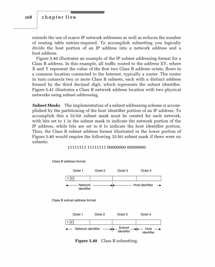
268 c h a p t e r f i v e
extends the use of scarce IP network addresses as well as reduces the numberof routing table entries required. To accomplish subnetting you logicallydivide the host portion of an IP address into a network address and ahost address.
Figure 5.40 illustrates an example of the IP subnet addressing format for aClass B address. In this example, all traffic routed to the address XY, whereX and Y represent the value of the first two Class B address octets, flows toa common location connected to the Internet, typically a router. The routerin turn connects two or more Class B subnets, each with a distinct addressformed by the third decimal digit, which represents the subnet identifier.Figure 5.41 illustrates a Class B network address location with two physicalnetworks using subnet addressing.
Subnet Masks The implementation of a subnet addressing scheme is accom-plished by the partitioning of the host identifier portion of an IP address. Toaccomplish this a 32-bit subnet mask must be created for each network,with bits set to 1 in the subnet mask to indicate the network portion of theIP address, while bits are set to 0 to indicate the host identifier portion.Thus, the Class B subnet address format illustrated in the lower portion ofFigure 5.40 would require the following 32-bit subnet mask if there were nosubnets:
11111111 11111111 00000000 00000000
Class B address format
Class B subnet address format
Octet 1 Octet 2 Octet 3 Octet 4
0
Networkidentifier
Host identifier
1
Octet 1 Octet 2 Octet 3 Octet 4
0
Network identifier Hostidentifier
1
Subnetidentifier
Figure 5.40 Class B subnetting.

networking hardware and software 269
Internet
Accessvia X.Y.Z.Z
X.Y.1.1 X.Y.1.2
X.Y.2.2X.Y.2.1
Router
Network X.Y.2.0
Network X.Y.1.0
Figure 5.41 A Class B network address location with two physical networksusing subnet addressing. IP datagrams with the destination address X.Y.Z.Z,where Z can be any decimal value representing a Class B network address thatcan consist of 256 subnets, with 256 hosts on each subnet.
The prior mask would then be entered as 255.255.0.0 in dotted deci-mal representation into a router configuration screen as well as in softwareconfiguration screens on TCP/IP program stacks operating on each subnet.Concerning the latter, you must then configure each station to indicate itssubnet and host identifier so that each station obtains a full 4-digit dotteddecimal address.
Because a Class B network address by default uses two bytes for the networkaddress and two for the host the prior mask does not allow for any subnets. Toallow for subnets we must internally (to our organization) extend the subnetmask into the host portion of the address. Each one-bit extension permits 2n
subnets to be defined. For example, consider the following subnet:
11111111 11111111 11100000 00000000
This subnet is 255.255.224 in dotted decimal and would support up toeight (23) subnets. Note that internally to our organization the number of bitpositions for hosts on a subnet becomes 16 − 3, or 13 positions. Thus, eachsubnet can have a maximum of 213 − 2 hosts as each subnet cannot be all 0’sor all 1’s, similar to regular network restrictions.
Domain Name Service
Addressing on a TCP/IP network occurs through the use of four decimal num-bers ranging from 0 to 255, which are separated from one another by a dot.

270 c h a p t e r f i v e
This dotted decimal notation represents a 32-bit address, which consists of anassigned network number and a host number as previously described duringour examination of IP addressing. Because numeric addresses are difficult towork with, TCP/IP also supports a naming convention based upon Englishwords or mnemonics that are both easier to work with and remember. Thetranslation of English words or mnemonics to 32-bit IP addresses is performedby a domain name server. Each network normally has at least one domainname server, and the communications established between such servers onTCP/IP networks connected to the Internet are referred to as a domain nameservice (DNS).
The DNS is the naming protocol used in the TCP/IP protocol suite, whichenables IP routing to occur indirectly through the use of names instead of IPaddresses. To accomplish this, DNS provides a domain name to IP addresstranslation service.
A domain is a subdivision of a wide area network. When applied tothe Internet where the capitalized I references the collection of networksinterconnected to one another, there are six top-level and seven recentlyadded domain names, which were specified by the Internet Corporation forAssigned Names and Numbers (ICANN) at the time this book was prepared.Those top-level domains are listed in Table 5.5.
Under each top-level domain the InterNIC will register subdomains, whichare assigned an IP network address. An organization receiving an IP networkaddress can further subdivide their domain into two or more subdomains. Inaddition, instead of using dotted decimal notation to describe the location ofeach host, they can assign names to hosts as long as they follow certain rulesand install a name server that provides IP address translation between namedhosts and their IP addresses.
To illustrate the operation of a name server, consider the network domainillustrated in Figure 5.42. In this example we will assume that a well-knowngovernment agency has a local area network with several computers thatwill be connected to the Internet. Each host address will contain the specificname of the host plus the names of all of the subdomains and domainsto which it belongs. Thus, the computer warrants would have the offi-cial address:
telnet.warrants.fbi.gov
Similarly, the computer cops would have the address:
ftp.cops.fbi.gov

networking hardware and software 271
TABLE 5.5 Internet Top-Level Domain Names
Domain Name Assignment
.COM Commercial organization
.EDU Educational organization
.GOV Government agency
.MIL Department of Defense
.NET Networking organization
.ORG Not-for-profit organization
Recently added.aevo Air-transport industry.biz Businesses.coop Cooperatives.info Information/services (unrestricted
use).museum Museums.name For registration by individuals.pro Accountants, lawyers, physicians,
and other professionals
Telnet
FBI . GOV
Warrants
Cops Robbers
ftp
Figure 5.42 A domain-naming hierarchy.
In examining the domain-naming structure illustrated in Figure 5.39 notethat computers were placed in subdomains using common Internet applicationnames, such as telnet and ftp. This is a common technique that organizationsuse to make it easier for network users within and outside of the organizationto remember mnemonics that represent specific hosts on their network.

272 c h a p t e r f i v e
Although domain names provide a mechanism for identifying objects con-nected to wide area networks, hosts in a domain require network addressesto transfer information. Thus, another host functioning as a name server isrequired to provide a name-to-address translation service.
Name Server
The name server plays an important role in TCP/IP networks. In addition toproviding a name-to-IP address translation service, it must recognize that anaddress is outside its administrative zone of authority. For example, assumea host located on the domain illustrated in Figure 5.42 will use the addressfred.microwear.com to transmit a message. The name server must recognizethat that address does not reside in the current domain and must forwardthe address to another name server for translation into an appropriate IPaddress. Because most domains are connected to the Internet via an Internetservice provider, the name server on the domain illustrated in Figure 5.42would have a pointer to the name server of the Internet service provider(ISP) and forward the query to that name server. The ISP’s name server willeither have an entry in its table-in-cache memory or forward the query toanother higher-level name server. Eventually, a name server will be reachedthat has administrative authority over the domain containing the host name toresolve and will return an IP address through a reversed hierarchy to providethe originating name server with a response to its query. Most name serverscache the results of previous name queries, which can considerably reduceoff-domain or Internet DNS queries. In the event a response is not received,possibly due to an incorrect name or the entry of a name no longer used, thelocal name server will generate a ‘‘failure to resolve’’ message after a periodof time that will be displayed on the requesting host’s display.
TCP/IP Configuration
The configuration of a station on a TCP/IP network normally requires thespecification of four IP addresses as well as the station’s host and domainnames. To illustrate the configuration of a TCP/IP station, Figures 5.43 through5.45 show the screen settings on a Microsoft Windows NT server used toconfigure the station as a participant on a TCP/IP network.
Figure 5.44 illustrates the Windows NT Network Settings dialog box withthe TCP/IP protocol selected in the installed network software box. Note thatat the top of that box the entry NWLink IPX/SPX Compatible Transport isshown. Windows NT has the ability to operate multiple protocol stacks to

networking hardware and software 273
Figure 5.43 Using the Windows NT Network Settings dialog box to configurethe use of the TCP/IP protocol.
Figure 5.44 The Windows NT TCP/IP configuration dialog box with entriesfor the IP address of the network interface, subnet mask, and default gateway.
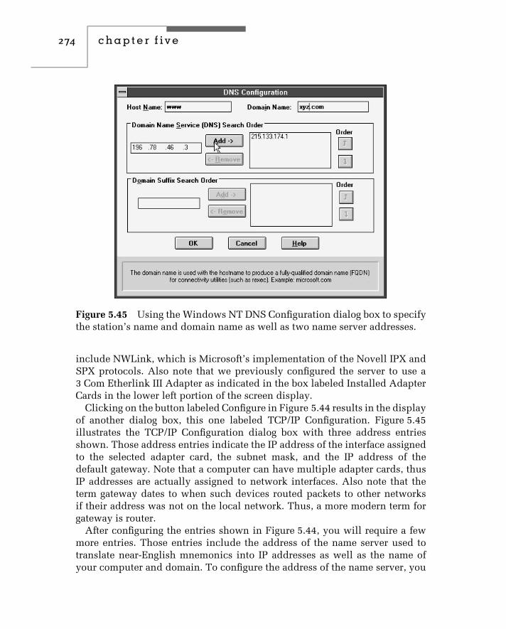
274 c h a p t e r f i v e
Figure 5.45 Using the Windows NT DNS Configuration dialog box to specifythe station’s name and domain name as well as two name server addresses.
include NWLink, which is Microsoft’s implementation of the Novell IPX andSPX protocols. Also note that we previously configured the server to use a3 Com Etherlink III Adapter as indicated in the box labeled Installed AdapterCards in the lower left portion of the screen display.
Clicking on the button labeled Configure in Figure 5.44 results in the displayof another dialog box, this one labeled TCP/IP Configuration. Figure 5.45illustrates the TCP/IP Configuration dialog box with three address entriesshown. Those address entries indicate the IP address of the interface assignedto the selected adapter card, the subnet mask, and the IP address of thedefault gateway. Note that a computer can have multiple adapter cards, thusIP addresses are actually assigned to network interfaces. Also note that theterm gateway dates to when such devices routed packets to other networksif their address was not on the local network. Thus, a more modern term forgateway is router.
After configuring the entries shown in Figure 5.44, you will require a fewmore entries. Those entries include the address of the name server used totranslate near-English mnemonics into IP addresses as well as the name ofyour computer and domain. To configure the address of the name server, you

networking hardware and software 275
would first click on the button labeled DNS in Figure 5.44. This action willresult in the display of a dialog box labeled DNS Configuration, which isshown in Figure 5.45.
The Windows NT DNS Configuration dialog box enables you to specifyyour host computer name and your domain name. Those entries are optional;however, if you do not include those entries and your local DNS uses thisconfiguration information, other TCP/IP users either on your network ora distant network will not be able to access your computer by enteringyour computer’s near-English address name, which in Figure 5.45 would bewww.xyz.com. Instead, users would have to know your numeric IP address.
The DNS entry area in Figure 5.45 allows you to specify up to three nameservers in the order they should be searched. Many organizations operate twoname servers, so the ability to enter three should suffice for most organizations.
Operating Multiple Stacks
In concluding this chapter we will use three Windows NT screens to expandupon illustrating the flexibility you can obtain from operating multiple
Figure 5.46 Using the Windows NT Connect Network Drive dialog box toview Windows and NetWare network devices.

276 c h a p t e r f i v e
protocol stacks. In the example we will shortly view, we will use Microsoft’sWindows NT to show how to access both Windows NT and NetWare networksas well as operate a Netscape browser to run a TCP/IP application.
Figure 5.46 illustrates the use of the Windows NT Connect Network Drivedialog box to view both Microsoft Windows and Novell NetWare networkdevices that can operate on a common network or network infrastruc-ture. By moving a highlight bar over a particular entry and clicking onthe entry, you obtain the ability to log into NT or NetWare servers oraccess-shared directories on NT devices. For those readers from Missouri,Figure 5.47 illustrates the execution of a NetWare server program viewedon a Windows NT workstation. In this example, the NT workstation is run-ning Microsoft’s NWLink IPX/SPX compatible protocol, which enables itto communicate in a client/server environment as a participant on a Net-Ware LAN.
Figure 5.47 Viewing the execution of a NetWare server program on a Win-dows NT workstation.

networking hardware and software 277
Figure 5.48 Using the Microsoft Internet Explorer browser to access thehome page of the author’s publisher.
For our last stack example, since we previously configured TCP/IP weshould be able to operate a TCP/IP application. Figure 5.48 illustrates the useof the Microsoft Internet Explorer browser to access the home page of thisauthor’s publisher. Thus, this short section illustrates the worth of operatingmultiple protocol stacks to access NT and NetWare servers as well as aWeb server.


c h a p t e r s i x
Bridging and SwitchingMethods and PerformanceIssuesIn Chapter 5, an overview of bridge operations was presented, along withinformation concerning the functionality of other local area network hard-ware and software components. That chapter deferred until now a detailedexamination of bridging methods, to include their network use and perfor-mance issues. In this chapter, we will focus our attention on those issues,examining different methods that bridges use for routing frames, performanceissues that govern their ability to examine and forward frames without intro-ducing network bottlenecks, and their typical employment for interconnectingLANs. Because LAN switches represent a special type of multiport bridge, wewill also focus our attention upon this topic later in this chapter. Thus, oncewe have an appreciation for the operation and utilization of bridges, we willturn our attention to LAN switches.
6.1 Bridging Methods
Bridges operate by examining MAC layer addresses, using the destinationand source addresses within a frame as a decision criterion to make theirforwarding decisions. Operating at the MAC layer, bridges are not addressed,and must therefore examine all frames that flow on a network. Because bridgesoperate at the MAC layer, they in effect terminate a collision domain. That is,if a collision is detected upon one port of a bridge, it is not propagated ontoany output port. This means that, unlike a repeater, a bridge can be used toextend the span of a LAN.
279

280 c h a p t e r s i x
Address Issues
Since bridges connect networks, it is important to ensure that duplicate MACaddresses do not occur on joined internal networks — a topology we will referto as an intranet. While duplicate addresses will not occur when universallyadministered addressing is used, when locally administered addressing isused duplicate addresses become possible. Thus, the addresses assigned tostations on separate networks joined to form an intranet should be reviewedbefore using bridges to connect two or more separate networks.
Two primary routing methods are used by bridges for connecting wired localarea networks: transparent or self-learning and source routing. Transparentbridges were originally developed to support the connection of Ethernetnetworks, as briefly described in Chapter 5.
Transparent Bridging
A transparent bridge examines MAC frames to learn the addresses of stationson the network, storing information in internal memory in the form of anaddress table. Thus, this type of bridge is also known as a self-learningbridge. To understand the operation of a transparent bridge in more detailand realize some of the limitations associated with the use of this device,consider the simple intranet illustrated in Figure 6.1. This intranet consists
A
Ethernet 1 Ethernet 2
BC D
Bridge 1 Bridge 2
Ethernet 3
E F
Port 1 Port 2 Port 1
Port 1 Port 2
Port 2
Bridge 2 port /address table
ABCD
EF
Port 1 Port 2
Bridge 1 port /address table
AB
CDEF
Figure 6.1 Transparent bridge operation. A transparent or self-learningbridge examines the source and destination addresses to form port/address orrouting tables in memory.

bridging and switching methods and performance issues 281
of three Ethernet local area network segments connected through the use oftwo self-learning bridges. For simplicity of illustration, only two workstationsare shown and labeled on each local area network. Those labels represent the48-bit MAC address of each station.
Port/Address Table Construction
As previously noted in Chapter 5, a bridge constructs its port/address tableby using what can be referred to as the ‘‘three F’s’’ — flooding, filtering, andforwarding. If a bridge encounters a frame with a destination address that isnot in its port/address table, it transmits the frame onto all other ports exceptthe port it was received on. If the destination address is in its port/addresstable and does not represent the port the frame was received on, the bridgeforwards the frame onto the port corresponding to the entry in the table forthe destination address. If the destination address is in the port/address tableand represents the port the frame was received on, there is no need to forwardthe frame. Thus, the frame is filtered by the bridge.
In examining the construction of bridge port/address tables for the networkshown in Figure 6.1, we will assume that each bridge operates as a transparentbridge. As frames flow on the Ethernet, bridge 1 examines the source addressof each frame. Eventually, after both stations A and B have become active, thebridge associates their address as being on port 1 of that device. Any frameswith a destination address other than stations A or B are considered to be onanother network. Thus, bridge 1 would eventually associate addresses C, D,E, and F with port 2, once it receives frames with those addresses in theirdestination address fields. Similarly, bridge 2 constructs its own port/addresstable. Since frames from Ethernet 1 and 1 Ethernet 2 can have source addressesof A, B, C, or D, eventually the port/address table of bridge 2 associates thoseaddresses with port 1 of that device. Since frames from Ethernet 1 or Ethernet 2with a destination address of E or F are not on those local area networks,bridge 2 then associates those addresses with port 2 of that device.
The port/address tables previously shown in Figure 6.1 are normally storedin bridge memory sorted by MAC address. In addition, the time the entryoccurred is also added to the table, resulting in a three-column table. Thetime of occurrence is used by bridges to periodically purge old entries. Entrypurging is important because inactive entries both use finite memory andextend the search time associated with the reading of each frame receivedon a bridge port and its comparison to entries in the port/address table. Thissearching is required to determine if the frame is to be forwarded along withthe port onto which the frame should be placed.

282 c h a p t e r s i x
Advantages
One of the key advantages of a transparent bridge is that it operates indepen-dently of the contents of the information field and is protocol-independent.Because this type of bridge is self-learning, it requires no manual configurationand is essentially a ‘‘plug and play’’ device. Thus, this type of bridge is attrac-tive for connecting a few local area networks together, and is usually sufficientfor most small and medium-sized businesses. Unfortunately, its use limits thedevelopment of certain interconnection topologies, as we will soon see.
Disadvantages
To see the disadvantages associated with transparent bridges, considerFigure 6.2, in which the three Ethernet local area networks are interconnectedthrough the use of three bridges. In this example, the interconnected networksform a circular or loop topology. Because a transparent bridge views stationsas being connected to either port 1 or port 2, a circular or loop topology willcreate problems. Those problems can result in an unnecessary duplicationof frames, which not only degrades the overall level of performance of the
A B E
C
F
Bridge 1
Bridge 3Bridge 2
Port 1Port 1
Port 2
Port 2
Port 1
Port 2
Ethernet 1 Ethernet 2
Ethernet 3
D
Figure 6.2 Transparent bridges do not support network loops. The construc-tion of a circular or loop topology with transparent bridges can result in anunnecessary duplication of frames, and may confuse end stations. To avoidthese problems, the Spanning Tree Protocol (STP) opens a loop by placingone bridge in a standby mode of operation.

bridging and switching methods and performance issues 283
interconnected networks, but will quite possibly confuse the end stations. Forexample, consider a frame whose source address is A and whose destinationaddress is F. Both bridge 1 and bridge 2 will forward the frame. Althoughbridge 1 will forward the frame to its appropriate network using the mostdirect route, the frame will also be forwarded via bridge 2 and bridge 3to Ethernet 2, resulting in a duplicate frame arriving at workstation F. Atstation F, a mechanism would be required to reject duplicate frames. Even ifsuch a mechanism is available, the additional traffic flowing across multipleinternet paths would result in an increase in network usage. This, in turn,would saturate some networks, while significantly reducing the level ofperformance of other networks. For these reasons, transparent bridging isprohibited from creating a loop or circular topology. However, transparentbridging supports concurrently active multiple bridges, using an algorithmknown as the spanning tree to determine which bridges should forward andwhich bridges should only filter frames.
Spanning Tree Protocol
The problem of active loops was addressed by the IEEE Committee 802 inthe 802.1D standard with an intelligent algorithm known as the SpanningTree Protocol (STP). The STP, based on graph theory, converts a loop into atree topology by disabling a link. This action ensures there is a unique pathfrom any node in an intranet to every other node. Disabled nodes are thenkept in a standby mode of operation until a network failure occurs. At thattime, the STP will attempt to construct a new tree using any of the previouslydisabled links.
Operation
To illustrate the operation of the STP, we must first become familiar withthe difference between the physical and active topology of bridged networks.In addition, there are a number of terms associated with the spanning treealgorithm, as defined by the protocol, that we should become familiar with.Thus, we will also review those terms before discussing the operation ofthe algorithm.
Physical versus Active Topology
In transparent bridging, a distinction is made between the physical and activetopology resulting from bridged local area networks. This distinction enablesthe construction of a network topology in which inactive but physically

284 c h a p t e r s i x
constructed routes can be placed into operation if a primary route should fail,and in which the inactive and active routes would form an illegal circularpath violating the spanning tree algorithm if both routes were active at thesame time.
The top of Figure 6.3 illustrates one possible physical topology of bridgednetworks. The cost (C) assigned to each bridge will be discussed later in thischapter. The lower portion of Figure 6.3 illustrates a possible active topologyfor the physical configuration shown at the top of that illustration.
When a bridge is used to construct an active path, it will forward framesthrough those ports used to form active paths. The ports through whichframes are forwarded are said to be in a forwarding state of operation. Portsthat cannot forward frames because their operation forms a loop are said to bein a blocking state of operation.
Under the spanning tree algorithm, a port in a blocking state can be placedinto a forwarding state to provide a path that becomes part of the activenetwork topology. This new path usually occurs because of the failure ofanother path, bridge component, or the reconfiguration of interconnectednetworks, and must not form a closed loop.
Spanning Tree Algorithm
The basis for the spanning tree algorithm is a tree structure, since a tree formsa pattern of connections that has no loops. The term spanning is used becausethe branches of a tree structure span or connect subnetworks.
As a review for readers unfamiliar with graph theory, let’s examine theconcept behind spanning trees. To appropriately do so we need a pointof reference, so let’s begin with the graph structure shown at the top ofFigure 6.4. A spanning tree of a graph is a subgraph that connects all nodes andrepresents a tree. The graph shown at the top of Figure 6.4 has eight distinctspanning trees. The lower portion of Figure 6.4 illustrates the spanning treesassociated with the graph structure illustrated at the top of the previouslyreferenced figure.
Minimum Spanning Tree
Suppose the links connecting each node are assigned a length or weight. Then,the weight of a tree represents the sum of its links or edges. If the weightor length of the links or tree edges differ, then different tree structures willhave different weights. Thus, the identification of the minimum spanning treerequires us to examine each of the spanning trees supported by a graph andidentify the structure that has the minimum length or weight.

bridging and switching methods and performance issues 285
Token-ring 1
Token-ring 1
Token-ring 2
Token-ring 2
B1C =10
B2C =10
B3C =15
B4C =15
B5C =10
Ethernet 1
Ethernet 1
Ethernet 3
Ethernet 3
Ethernet 2
Ethernet 2
B1 B2 B3
B4
B5
Legend: B = BridgeC = Cost
(a) Physical topology
(b) Active topology
Figure 6.3 Physical versus active topology. When transparent bridges areused, the active topology cannot form a closed loop in the intranet.

286 c h a p t e r s i x
(a) Network graph
(b) Possible spanning trees
Figure 6.4 Forming spanning trees from a network graph.
The identification of the minimum spanning tree can be accomplishedby listing all spanning trees and finding the minimum weight or lengthassociated with the list. This is a brute force method that always works butis not exactly efficient, especially when a graph becomes complex and cancontain a significant number of trees. A far better method is obtained by theuse of an appropriate algorithm.
Kruskal’s Algorithm
There are several popular algorithms developed for solving the minimumspanning tree of a graph. One of those algorithms is the Kruskal algorithmwhich is relatively easy to understand and will be used to illustrate thecomputation of a minimum spanning tree. Because we need weights orlengths assigned to each edge or link in a graph, let’s revise the network graphpreviously shown in Figure 6.4 and add some weights. Figure 6.5 illustratesthe weighted graph.

bridging and switching methods and performance issues 287
A8
1 4
6C D
B
3
Figure 6.5 A weighted network graph.
Kruskal’s algorithm can be expressed as follows:
1. Sort the edges of the graph (G) in their increasing order by weightor length.
2. Construct a subgraph (S) of G and initially set it to the empty state.3. For each edge (e) in sorted order:
If the endpoints of the edges (e) are disconnected in S, add them to S.
Using the graph shown in Figure 6.5, let’s apply Kruskal’s algorithmas follows:
1. The sorted edges of the graph in their increasing order by weight orlength produces the following table:
Edge Weight/Length
A-C 1
B-D 3
C-B 4
C-D 6
A-B 8
2. Set the subgraph of G to the empty state. Thus, S = null.3. For each edge add to S as long as the endpoints are disconnected. Thus,
the first operation produces:
A
C
S = A,C or

288 c h a p t e r s i x
The next operation produces:
A
S = (A,C) + (B,D) or
C
B
D
The third operation produces:
A
S = (A,B) + (B,D) + (C,B) or
C
B
D
Note that we cannot continue as the endpoints in S are now all connected.Thus, the minimum spanning tree consists of the edges or links (A, B) +(B, D) + (C, B) and has the weight 1 + 4 + 3, or 7. Now that we have anappreciation for the method by which a minimum spanning tree is formed, let’sturn our attention to its applicability in transparent bridge-based networks.
Similar to the root of a tree, one bridge in a spanning tree network willbe assigned to a unique position in the network. Known as the root bridge,this bridge is assigned as the top of the spanning tree, and because of thisposition, it has the potential to carry the largest amount of intranet traffic dueto its position.
Because bridges and bridge ports can be active or inactive, a mechanismis required to identify bridges and bridge ports. Each bridge in a spanningtree network is assigned a unique bridge identifier. This identifier is the MACaddress on the bridge’s lowest port number and a two-byte bridge prioritylevel. The priority level is defined when a bridge is installed and functionsas a bridge number. Similar to the bridge priority level, each adapter ona bridge that functions as a port has a two-byte port identifier. Thus, theunique bridge identifier and port identifier enable each port on a bridge to beuniquely identified.
Path Cost
Under the spanning tree algorithm, the difference in physical routes betweenbridges is recognized, and a mechanism is provided to indicate the preferencefor one route over another. That mechanism is accomplished by the ability

bridging and switching methods and performance issues 289
to assign a path cost to each path. Thus, you could assign a low cost to apreferred route and a high cost to a route you only want to be used in abackup situation.
Once path costs are assigned to each path in an intranet, each bridge willhave one or more costs associated with different paths to the root bridge. Oneof those costs is lower than all other path costs. That cost is known as thebridge’s root path cost, and the port used to provide the least path cost towardthe root bridge is known as the root port.
Designated Bridge
As previously discussed, the spanning tree algorithm does not permit activeloops in an interconnected network. To prevent this situation from occurring,only one bridge linking two networks can be in a forwarding state at anyparticular time. That bridge is known as the designated bridge, while all otherbridges linking two networks will not forward frames and will be in a blockingstate of operation.
Constructing the Spanning Tree
The spanning tree algorithm employs a three-step process to develop an activetopology. First, the root bridge is identified. To accomplish this, each bridgein the intranet will initially assume it is the root bridge. To determine whichbridge should actually act as the root bridge, each bridge will periodicallytransmit bridge protocol data unit (BPDU) frames that are described in thefollowing section. BPDU frames under Ethernet version 2 are referred to asHELLO frames or messages and are transmitted on all bridge ports. EachBPDU frame includes the priority of the bridge defined at installation time. Asthe bridges in the intranet periodically transmit their BPDU frames, bridgesreceiving a BPDU with a lower priority value than its own cease transmittingtheir BPDUs; however, they forward BPDUs with a lower priority value.Thus, after a short period of time the bridge with the lowest priority valueis recognized as the root bridge. In Figure 6.3b we will assume bridge 1 wasselected as the root bridge. Next, the path cost from each bridge to the rootbridge is determined, and the minimum cost from each bridge becomes theroot path cost. The port in the direction of the least path cost to the rootbridge, known as the root port, is then determined for each bridge. If the rootpath cost is the same for two or more bridges linking LANs, then the bridgewith the highest priority will be selected to furnish the minimum path cost.Once the paths are selected, the designated ports are activated.

290 c h a p t e r s i x
In examining Figure 6.3a, let us now use the cost entries assigned toeach bridge. Let us assume that bridge 1 was selected as the root bridge,since we expect a large amount of traffic to flow between Token-Ring 1 andEthernet 1 networks. Therefore, bridge 1 will become the designated bridgebetween Token-Ring 1 and Ethernet 1 networks. Here the term designatedbridge references the bridge that has the bridge port with the lowest-cost pathto the root bridge.
In examining the path costs to the root bridge, note that the path throughbridge 2 was assigned a cost of 10, while the path through bridge 3 wasassigned a cost of 15. Thus, the path from Token-Ring 2 via bridge 2 to Token-Ring 1 becomes the designated bridge between those two networks. Hence,Figure 6.3b shows bridge 3 inactive by the omission of a connection to theToken-Ring 2 network. Similarly, the path cost for connecting the Ethernet 3network to the root bridge is lower by routing through the Token-Ring 2 andToken-Ring 1 networks. Thus, bridge 5 becomes the designated bridge for theEthernet 3 and Token-Ring 2 networks.
Bridge Protocol Data Unit
As previously noted, bridges obtain topology information by the use ofbridge protocol data unit (BPDU) frames. Once a root bridge is selected, thatbridge is responsible for periodically transmitting a ‘‘HELLO’’ BPDU frameto all networks to which it is connected. According to the spanning treeprotocol, HELLO frames must be transmitted every 1 to 10 seconds. TheBPDU has the group MAC address 800143000000, which is recognized byeach bridge. A designated bridge will then update the path cost and timinginformation and forward the frame. A standby bridge will monitor the BPDUs,but will not update nor forward them. If the designated bridge does notreceive a BPDU on its root port for a predefined period of time (default is20 seconds), the designated bridge will assume that either a link or devicefailure occurred. That bridge, if it is still receiving configuration BPDU frameson other ports, will then switch its root port to a port that is receiving the bestconfiguration BPDUs.
When a standby bridge is required to assume the role of the root or designatedbridge, the HELLO BPDU will indicate that a standby bridge should becomea designated bridge. The process by which bridges determine their role ina spanning tree network is iterative. As new bridges enter a network, theyassume a listening state to determine their role in the network. Similarly,when a bridge is removed, another iterative process occurs to reconfigure theremaining bridges.

bridging and switching methods and performance issues 291
Although the STP algorithm procedure eliminates duplicate frames anddegraded intranet performance, it can be a hindrance for situations wheremultiple active paths between networks are desired. In addition, if a link ordevice fails, the time required for a new spanning tree to be formed via thetransmission of BPDUs can easily require 45 to 60 seconds or more. Anotherdisadvantage of STP occurs when it is used in remote bridges connectinggeographically dispersed networks. For example, returning to Figure 6.2,suppose Ethernet 1 were located in Los Angeles, Ethernet 2 in New York, andEthernet 3 in Atlanta. If the link between Los Angeles and New York wereplaced in a standby mode of operation, all frames from Ethernet 2 routed toEthernet 1 would be routed through Atlanta. Depending on the traffic betweennetworks, this situation might require an upgrade in the bandwidth of the linksconnecting each network to accommodate the extra traffic flowing throughAtlanta. Since the yearly cost of upgrading a 56- or 64-Kbps circuit to a 128-Kbps fractional T1 link can easily exceed the cost of a bridge or router, youmight wish to consider the use of routers to accommodate this networkingsituation. In comparison, when using local bridges, the higher operatingrate of local bridges in interconnecting local area networks normally allowsan acceptable level of performance when LAN traffic is routed through anintermediate bridge.
Protocol Dependency
Another problem associated with the use of transparent bridges concerns thedifferences between Ethernet and IEEE 802.3 frame field compositions. Asnoted in Chapter 4, the Ethernet frame contains a type field that indicatesthe higher-layer protocol in use. Under the IEEE 802.3 frame format, the typefield is replaced by a length field, and the data field is subdivided to includelogical link control (LLC) information in the form of destination (DSAP) andsource (SSAP) service access points. Here, the DSAP and SSAP are similar tothe type field in an Ethernet frame: they also point to a higher-level process.Unfortunately, this small difference can create problems when you are usinga transparent bridge to interconnect Ethernet and IEEE 802.3 networks.
The top portion of Figure 6.6 shows the use of a bridge to connect anAppleTalk network supporting several Macintosh computers to an Ethernetnetwork on which a Digital Equipment Corporation VAX computer is located.Although the VAX may be capable of supporting DecNet Phase IV, whichis true Ethernet, and AppleTalk if both modules are resident, a pointer isrequired to direct the IEEE 802.3 frames generated by the Macintosh tothe right protocol on the VAX. Unfortunately, the Ethernet connection used

292 c h a p t e r s i x
Decphase IV
Appletalk
Ethernet NIC
Ethernet
Ethernet
B
M
M
M
IEEE 802.3
IEEE 802.3
Length InformationInformation
InformationDSAP SSAP Control
Type
Frame differences
Legend:= Workstation= Macintosh
Figure 6.6 Protocol differences preclude linking IEEE 802.3 and Ethernetnetworks using transparent bridges. A Macintosh computer connected on anIEEE 802.3 network using AppleTalk will not have its frame pointed to theright process on a VAX on an Ethernet. Thus, the differences between Ethernetand IEEE 802.3 networks require transparent bridges for interconnectingsimilar networks.
by the VAX will not provide the required pointer. This explains why youshould avoid connecting Ethernet and IEEE 802.3 networks via transparentbridges. Fortunately, almost all Ethernet NICs manufactured today are IEEE802.3–compatible to alleviate this problem; however, older NICs may operateas true Ethernets and result in the previously mentioned problem.
Source Routing
Source routing is a bridging technique developed by IBM for connectingToken-Ring networks. The key to the implementation of source routing is the

bridging and switching methods and performance issues 293
use of a portion of the information field in the Token-Ring frame to carryrouting information and the transmission of discovery packets to determinethe best route between two networks.
The presence of source routing is indicated by the setting of the first bitposition in the source address field of a Token-Ring frame to a binary 1. Whenset, this indicates that the information field is preceded by a route informationfield (RIF), which contains both control and routing information.
The RIF Field
Figure 6.7 illustrates the composition of a Token-Ring RIF. This field isvariable in length and is developed during a discovery process, describedlater in this section.
2 bytes Up to 16 bytes
Control Ring #
Ring #
Ring # Bridge # Bridge #
Bridge #
12 bits 4 bitsB B B LL L LL LFLFLFLFR R RD
Field format
B are broadcast bitsBit settings Designator
Bit settings
0XX10X11X
NonbroadcastAll-routes broadcastSingle route broadcast
L are length bits which denote length of the RIF in bytesD is direction bitLF identifies largest frame
Size in bytes
000001010011100101110111
5161500205244728191ReservedReservedUsed in all-routes broadcast frame
R are reserved bits
Figure 6.7 Token-Ring route information field. The Token-Ring RIF is vari-able in length.

294 c h a p t e r s i x
The control field contains information that defines how information will betransferred and interpreted and what size the remainder of the RIF will be. Thethree broadcast bit positions indicate a nonbroadcast, all-routes broadcast, orsingle-route broadcast situation. A nonbroadcast designator indicates a localor specific route frame. An all-routes broadcast designator indicates that aframe will be transmitted along every route to the destination station. Asingle-route broadcast designator is used only by designated bridges to relaya frame from one network to another. In examining the broadcast bit settingsshown in Figure 6.7, note that the letter X indicates an unspecified bit settingthat can be either a 1 or 0.
The length bits identify the length of the RIF in bytes, while the D bitindicates how the field is scanned, left to right or right to left. Since vendorshave incorporated different memory in bridges which may limit frame sizes,the LF bits enable different devices to negotiate the size of the frame. Normally,a default setting indicates a frame size of 512 bytes. Each bridge can selecta number, and if it is supported by other bridges, that number is then usedto represent the negotiated frame size. Otherwise, a smaller number usedto represent a smaller frame size is selected, and the negotiation process isrepeated. Note that a 1500-byte frame is the largest frame size supportedby Ethernet IEEE 802.3 networks. Thus, a bridge used to connect Ethernetand Token-Ring networks cannot support the use of Token-Ring framesexceeding 1500 bytes.
Up to eight route number subfields, each consisting of a 12-bit ring numberand a 4-bit bridge number, can be contained in the routing information field.This permits two to eight route designators, enabling frames to traverse upto eight rings across seven bridges in a given direction. Both ring numbersand bridge numbers are expressed as hexadecimal characters, with three hexcharacters used to denote the ring number and one hex character used toidentify the bridge number.
Operation Example
To illustrate the concept behind source routing, consider the intranet illus-trated in Figure 6.8. In this example, let us assume that two Token-Ringnetworks are located in Atlanta and one network is located in New York.
Each Token-Ring and bridge is assigned a ring or bridge number. For sim-plicity, ring numbers R1, R2, and R3 are used here, although as previouslyexplained, those numbers are actually represented in hexadecimal. Simi-larly, bridge numbers are shown here as B1, B2, B3, B4, and B5 instead ofhexadecimal characters.

bridging and switching methods and performance issues 295
AA
A
A
A
A
A
B R1
R1
R1 R1
R1
R1
R1
B1 B2
B2
B1
B1R3
R3
R3
0
0
C
D
B5
B5R2
R2R2
B4
B4B4
R2 B3
B3
B3
B3
New York
Atlanta
Figure 6.8 Source routing discovery operation. The route discovery processresults in each bridge entering the originating ring number and its bridgenumber into the RIF.
When a station wants to originate communications, it is responsible forfinding the destination by transmitting a discovery packet to network bridgesand other network stations whenever it has a message to transmit to a newdestination address. If station A wishes to transmit to station C, it sends aroute discovery packet containing an empty RIF and its source address, asindicated in the upper left portion of Figure 6.8. This packet is recognizedby each source routing bridge in the network. When a source routing bridgereceives the packet, it enters the packet’s ring number and its own bridgeidentifier in the packet’s routing information field. The bridge then transmitsthe packet to all of its connections except the connection on which the packetwas received, a process known as flooding. Depending on the topology of theinterconnected networks, it is more than likely that multiple copies of thediscovery packet will reach the recipient. This is illustrated in the upper rightcorner of Figure 6.8, in which two discovery packets reach station C. Here, onepacket contains the sequence R1B1R1B2R30 — the zero indicates that there isno bridging in the last ring. The second packet contains the route sequenceR1B3R2B4R2B5R30. Station C then picks the best route, based on either themost direct path or the earliest arriving packet, and transmits a response to

296 c h a p t e r s i x
the discover packet originator. The response indicates the specific route touse, and station A then enters that route into memory for the duration of thetransmission session.
Under source routing, bridges do not keep routing tables like transparentbridges. Instead, tables are maintained at each station throughout the network.Thus, each station must check its routing table to determine what route framesmust traverse to reach their destination station. This routing method resultsin source routing using distributed routing tables instead of the centralizedrouting tables used by transparent bridges.
Advantages
There are several advantages associated with source routing. One advantage isthe ability to construct mesh networks with loops for a fault-tolerant design;this cannot be accomplished with the use of transparent bridges. Anotheradvantage is the inclusion of routing information in the information frames.Several vendors have developed network management software products thatuse that information to provide statistical information concerning intranetactivity. Those products may assist you in determining how heavily yourwide area network links are being used, and whether you need to modify thecapacity of those links; they may also inform you if one or more workstationsare hogging communications between networks.
Disadvantages
Although the preceding advantages are considerable, they are not withouta price. That price includes a requirement to identify bridges and linksspecifically, higher bursts of network activity, and an incompatibility betweenToken-Ring and Ethernet networks. In addition, because the structure of theToken-Ring RIF supports a maximum of seven entries, routing of frames isrestricted to crossing a maximum of seven bridges.
When using source routing bridges to connect Token-Ring networks, youmust configure each bridge with a unique bridge/ring number. In addition,unless you wish to accept the default method by which stations select a frameduring the route discovery process, you will have to reconfigure your LANsoftware. Thus, source routing creates an administrative burden not incurredby transparent bridges.
Due to the route discovery process, the flooding of discovery frames occurs inbursts when stations are turned on or after a power outage. Depending uponthe complexity of an intranet, the discovery process can degrade network

bridging and switching methods and performance issues 297
performance. This is perhaps the most problematic for organizations thatrequire the interconnection of Ethernet and Token-Ring networks.
A source routing bridge can be used only to interconnect Token-Ringnetworks, since it operates on RIF data not included in an Ethernet frame.Although transparent bridges can operate in Ethernet, Token-Ring, and mixedenvironments, their use precludes the ability to construct loop or meshtopologies, and inhibits the ability to establish operational redundant pathsfor load sharing. Another problem associated with bridging Ethernet andToken-Ring networks involves the RIF in a Token-Ring frame. Unfortunately,different LAN operating systems use the RIF data in different ways. Thus,the use of a transparent bridge to interconnect Ethernet and Token-Ringnetworks may require the same local area network operating system on eachnetwork. To alleviate these problems, several vendors introduced sourcerouting transparent (SRT) bridges, which function in accordance with theIEEE 802.1D standard approved during 1992.
Source Routing Transparent Bridges
A source routing transparent bridge supports both IBM’s source routing andthe IEEE transparent STP operations. This type of bridge can be consideredtwo bridges in one; it has been standardized by the IEEE 802.1 committee asthe IEEE 802.1D standard.
Operation
Under source routing, the MAC packets contain a status bit in the source fieldthat identifies whether source routing is to be used for a message. If sourcerouting is indicated, the bridge forwards the frame as a source routing frame. Ifsource routing is not indicated, the bridge determines the destination addressand processes the packet using a transparent mode of operation, using routingtables generated by a spanning tree algorithm.
Advantages
There are several advantages associated with source routing transparentbridges. First and perhaps foremost, they enable different networks to usedifferent local area network operating systems and protocols. This capabil-ity enables you to interconnect networks developed independently of oneanother, and allows organization departments and branches to use LANoperating systems without restriction. Secondly, also a very important con-sideration, source routing transparent bridges can connect Ethernet and

298 c h a p t e r s i x
Token-Ring networks while preserving the ability to mesh or loop Token-Ring networks. Thus, their use provides an additional level of flexibility fornetwork construction.
Translating Operations
When interconnecting Ethernet/IEEE 802.3 and Token-Ring networks, thedifference between frame formats requires the conversion of frames. A bridgethat performs this conversion is referred to as a translating bridge.
As previously noted in Chapter 4, there are several types of Ethernet frames,such as Ethernet, IEEE 802.3, Novell’s Ethernet-802.3, and Ethernet-SNAP.The latter two frames represent variations of the physical IEEE 802.3 frameformat. Ethernet and Ethernet-802.3 do not use logical link control, while IEEE802.3 CSMA/CD LANs specify the use of IEEE 802.2 logical link control. Incomparison, all IEEE 802.5 Token-Ring networks either directly or indirectlyuse the IEEE 802.2 specification for logical link control.
The conversion from IEEE 802.3 to IEEE 802.5 can be accomplished bydiscarding portions of the IEEE 802.3 frame not applicable to a Token-Ring frame, copying the 802.2 LLC protocol data unit (PDU) from oneframe to another, and inserting fields applicable to the Token-Ring frame.Figure 6.9 illustrates the conversion process performed by a translating bridge
Preamble DA
DA
SA
SA
Length DSAP
DSAP
SSAP
SSAP
Control
Control
Information
Information
FCS
FCS
Discardinsert
Discardinsert
Discardinsert CopyCopy
SD AC FC RIF ED FS
Legend:
DASAACFCRIFDSAPSSAPEDFS
= Destination Address= Source Address= Access Control= Frame Control= Routing Information Field= Destination Service Access Point= Source Service Access Point= End Delimiter= Frame Status Field
IEEE 802.3
Figure 6.9 IEEE 802.3 to 802.5 frame conversion.

bridging and switching methods and performance issues 299
Preamble DA
DA
SA
SA DSAP SSAP Control
FCS FCS
FCS
Discardinsert
Discardinsert
CopyCopy
SD AC FC RIF ED FS
Legend:
DASAACFCRIFDSAPSSAPEDFSOC
= Destination Address= Source Address= Access Control= Frame Control= Routing Information Field= Destination Service Access Point= Source Service Access Point= End Delimiter= Frame Status Field= Organization Code
Type
Type
Data
DataOC
Ethernet
Token-ring
Figure 6.10 Ethernet to Token-Ring frame conversion.
linking an IEEE 802.3 network to an IEEE 802.5 network. Note that fieldsunique to the IEEE 802.3 frame are discarded, while fields common to bothframes are copied. Fields unique to the IEEE 802.5 frame are inserted bythe bridge.
Since an Ethernet frame, as well as Novell’s Ethernet-802.3 frame, does notsupport logical link control, the conversion process to IEEE 802.5 requiresmore processing. In addition, each conversion is more specific and may ormay not be supported by a specific translating bridge. For example, considerthe conversion of Ethernet frames to Token-Ring frames. Since Ethernet doesnot support LLC PDUs, the translation process results in the generation of aToken-Ring-SNAP frame. This conversion or translation process is illustratedin Figure 6.10.
6.2 Bridge Network Utilization
In this section, we will examine the use of bridges to interconnect separatelocal area networks and to subdivide networks to improve performance.In addition, we will focus our attention on how we can increase network

300 c h a p t e r s i x
availability by employing bridges to provide alternate communications pathsbetween networks.
Serial and Sequential Bridging
The top of Figure 6.11 illustrates the basic use of a bridge to interconnect twonetworks serially. Suppose that monitoring of each network indicates a highlevel of intranetwork use. One possible configuration to reduce intra-LANtraffic on each network can be obtained by moving some stations off each ofthe two existing networks to form a third network. The three networks wouldthen be interconnected through the use of an additional bridge, as illustratedin the middle portion of Figure 6.11. This extension results in sequential orcascaded bridging, and is appropriate when intra-LAN traffic is necessary butminimal. This intranet topology is also extremely useful when the length of anEthernet must be extended beyond the physical cabling of a single network. Bylocating servers appropriately within each network segment, you may be ableto minimize inter-LAN transmission. For example, the first network segmentcould be used to connect marketing personnel, while the second and thirdsegments could be used to connect engineering and personnel departments.This might minimize the use of a server on one network by persons connectedto another network segment.
A word of caution is in order concerning the use of bridges. Bridgingforms what is referred to as a flat network topology, because it makes itsforwarding decisions using layer 2 MAC addresses, which cannot distinguishone network from another. This means that broadcast traffic generated onone segment will be bridged onto other segments which, depending uponthe amount of broadcast traffic, can adversely affect the performance onother segments.
The only way to reduce broadcast traffic between segments is to use afiltering feature included with some bridges or install routers to link seg-ments. Concerning the latter, routers operate at the network layer and forwardpackets explicitly addressed to a different network. Through the use of net-work addresses for forwarding decisions, routers form hierarchical structurednetworks, eliminating the so-called broadcast storm effect that occurs whenbroadcast traffic generated from different types of servers on different segmentsare automatically forwarded by bridges onto other segments.
Both serial and sequential bridging are applicable to transparent, sourcerouting, and source routing transparent bridges that do not provide redun-dancy nor the ability to balance traffic flowing between networks. Each of thesedeficiencies can be alleviated through the use of parallel bridging. However,

bridging and switching methods and performance issues 301
B
B
B
B
B
Serial bridging
Sequential or cascaded bridging
Parallel bridging
Legend:
B= Workstation= Bridge
Figure 6.11 Serial, sequential, and parallel bridging.
this bridging technique creates a loop and is only applicable to source routingand source routing transparent bridges.
Parallel Bridging
The lower portion of Figure 6.11 illustrates the use of parallel bridges tointerconnect two Token-Ring networks. This bridging configuration permits
302 c h a p t e r s i x
one bridge to back up the other, providing a level of redundancy for linkingthe two networks as well as a significant increase in the availability of onenetwork to communicate with another. For example, assume the availabilityof each bridge used at the top of Figure 6.11 (serial bridging) and bottomof Figure 6.11 (parallel bridging) is 90 percent. The availability through twoserially connected bridges would be 0.9 × 0.9 (availability of bridge 1 ×availability of bridge 2), or 81 percent. In comparison, the availability throughparallel bridges would be 1 − (0.1 × 0.1), which is 99 percent.
The dual paths between networks also improve inter-LAN communicationsperformance, because communications between stations on each network canbe load balanced. The use of parallel bridges can thus be expected to provide ahigher level of inter-LAN communications than the use of serial or sequentialbridges. However, as previously noted, this topology is not supported bytransparent bridging.
Star Bridging
With a multiport bridge, you can connect three or more networks to form astar intranet topology. The top portion of Figure 6.12 shows the use of onebridge to form a star topology by interconnecting four separate networks.This topology, or a variation on this topology, could be used to interconnectnetworks on separate floors within a building. For example, the top networkcould be on floor N + 1, while the bottom network could be on floor N − 1 ina building. The bridge and the two networks to the left and right of the bridgemight then be located on floor N.
Although star bridging permits several networks located on separate floorswithin a building to be interconnected, all intranet data must flow throughone bridge. This can result in both performance and reliability constraints totraffic flow. Thus, to interconnect separate networks on more than a few floorsin a building, you should consider using backbone bridging.
Backbone Bridging
The lower portion of Figure 6.12 illustrates the use of backbone bridging. Inthis example, one network runs vertically through a building with Ethernetribs extending from the backbone onto each floor. Depending upon the amountof intranet traffic and the vertical length required for the backbone network,the backbone can be either a conventional Ethernet bus-based network or afiber-optic backbone.

bridging and switching methods and performance issues 303
Star bridging
Backbone bridging
B
B
B
B
B
Legend:= Workstation= Bridge
Figure 6.12 Star and backbone bridging.
6.3 Bridge Performance Issues
The key to obtaining an appropriate level of performance when intercon-necting networks is planning. The actual planning process will depend uponseveral factors, such as whether separate networks are in operation, the typeof networks to be connected, and the type of bridges to be used — localor remote.
Traffic Flow
If separate networks are in operation and you have appropriate monitoringequipment, you can determine the traffic flow on each of the networks to be

304 c h a p t e r s i x
interconnected. Once this is accomplished, you can expect an approximate10- to 20-percent increase in network traffic. This additional traffic representsthe flow of information between networks after an interconnection links previ-ously separated local area networks. Although this traffic increase representsan average encountered by the author, your network traffic may not representthe typical average. To explore further, you can examine the potential forintranet communications in the form of electronic messages that may be trans-mitted to users on other networks, potential file transfers of word processingfiles, and other types of data that would flow between networks.
Network Types
The types of networks to be connected will govern the rate at which framesare presented to bridges. This rate, in turn, will govern the filtering rate atwhich bridges should operate so that they do not become bottlenecks ona network. For example, the maximum number of frames per second willvary between different types of Ethernet and Token-Ring networks, as well asbetween different types of the same network. The operating rate of a bridgemay thus be appropriate for connecting some networks while inappropriatefor connecting other types of networks.
Type of Bridge
Last but not least, the type of bridge — local or remote — will have a con-siderable bearing upon performance issues. Local bridges pass data betweennetworks at their operating rates. In comparison, remote bridges pass databetween networks using wide area network transmission facilities, whichtypically provide a transmission rate that is only a fraction of a local areanetwork operating rate. Now that we have discussed some of the aspectsgoverning bridge and intranet performance using bridges, let’s probe deeperby estimating network traffic.
Estimating Network Traffic
If we do not have access to monitoring equipment to analyze an existingnetwork, or if we are planning to install a new network, we can spend sometime developing a reasonable estimate of network traffic. To do so, we shouldattempt to classify stations into groups based on the type of general activityperformed, and then estimate the network activity for one station per group.This will enable us to multiply the number of stations in the group by the

bridging and switching methods and performance issues 305
station activity to determine the group network traffic. Adding up the activityof all groups will then provide us with an estimate of the traffic activity forthe network.
As an example of local area network traffic estimation, let us assume that ournetwork will support 20 engineers, 5 managers, and 3 secretaries. Table 6.1shows how we would estimate the network traffic in terms of the bit ratefor each station group and the total activity per group, and then sum up thenetwork traffic for the three groups that will use the network. In this example,which for the sake of simplicity does not include the transmission of data toa workstation printer, the total network traffic was estimated to be slightlybelow 50,000 bps.
TABLE 6.1 Estimating Network Traffic
ActivityMessage Size
(Bytes) Frequency Bit Rate∗
Engineering workstationsRequest program 1,500 1/hour 4Load program 480,000 1/hour 1,067Save files 120,000 2/hour 533Send/receive e-mail 2,000 2/hour 9Total engineering activity= 1,613 × 20 = 32,260 bps 1,613
Managerial workstationsRequest program 1,500 2/hour 7Load program 320,000 2/hour 1,422Save files 30,000 2/hour 134Send/receive e-mail 3,000 4/hour 27Total managerial activity= 1,590 × 5 = 7,950 bps 1,590
Secretarial workstationsRequest program 1,500 4/hour 14Load program 640,000 2/hour 2,844Save files 12,000 8/hour 214Send/receive e-mail 3,000 6/hour 40Total secretarial activity= 3,112 × 3 = 9,336 bps 3,112
Total estimated network activity= 49,546 bps
∗Note: Bit rate is computed by multiplying message rate by frequency by 8 bits/byte and dividingby 3,600 seconds/hour.

306 c h a p t e r s i x
To plan for the interconnection of two or more networks through the useof bridges, our next step should be to perform a similar traffic analysis foreach of the remaining networks. After this is accomplished, we can use thenetwork traffic to estimate inter-LAN traffic, using 10 to 20 percent of totalintranetwork traffic as an estimate of the intranet traffic that will result fromthe connection of separate networks.
Intranet Traffic
To illustrate the traffic estimation process for the interconnection of separateLANs, let us assume that network A’s traffic was determined to be 50,000 bps,while network B’s traffic was estimated to be approximately 100,000 bps.Figure 6.13 illustrates the flow of data between networks connected by a localbridge. Note that the data flow in each direction is expressed as a range, basedon the use of an industry average of 10 to 20 percent of network traffic routedbetween interconnected networks.
Network Types
Our next area of concern is to examine the types of networks to be intercon-nected. In doing so, we should focus our attention on the operating rate of
Network ALocal traffic50,000 bps
Network BLocal traffic100,000 bps
10,000 to 20,000 bps B
Total traffic 60,000 to 70,000 bps
Total traffic 105,000 to 110,000 bps
5,000 to 10,000 bps
Legend: = Workstation
Figure 6.13 Considering intranet data flow. To determine the traffic flow onseparate networks after they are interconnected, you must consider the flowof data onto each network from the other network.

bridging and switching methods and performance issues 307
each LAN. If network A’s traffic was estimated to be approximately 50,000 bps,then the addition of 10,000 to 20,000 bps from network B onto network A willraise network A’s traffic level to between 60,000 and 70,000 bps. Similarly,the addition of traffic from network A onto network B will raise network B’straffic level to between 105,000 and 110,000 bps. In this example, the resultingtraffic on each network is well below the operating rate of all types of localarea networks, and will not present a capacity problem for either network.
Bridge Type
As previously mentioned, local bridges transmit data between networks atthe data rate of the destination network. This means that a local bridge willhave a lower probability of being a bottleneck than a remote bridge, since thelatter provides a connection between networks using a wide area transmissionfacility, which typically operates at a fraction of the operating rate of a LAN.
In examining the bridge operating rate required to connect networks, wewill use a bottom-up and a top-down approach. That is, we will first determinethe operating rate in frames per second for the specific example previouslydiscussed. This will be followed by computing the maximum frame ratesupported by an Ethernet network.
For the bridge illustrated in Figure 6.13, we previously computed that itsmaximum transfer rate would be 20,000 bps from network B onto network A.This is equivalent to 2500 bytes per second. If we assume that data is trans-ported in 512-byte frames, this would be equivalent to 6 frames per second — aminimal transfer rate supported by every bridge manufacturer. However, whenremote bridges are used, the frame forwarding rate of the bridge will morethan likely be constrained by the operating rate of the wide area networktransmission facility.
Bridge Operational Considerations
A remote bridge wraps a LAN frame into a higher-level protocol packetfor transmission over a wide area network communications facility. Thisoperation requires the addition of a header, protocol control, error detection,and trailer fields, and results in a degree of overhead. A 20,000-bps data flowfrom network B to network A, therefore, could not be accommodated by atransmission facility operating at that data rate.
In converting LAN traffic onto a wide area network transmission facility,you can expect a protocol overhead of approximately 20 percent. Thus, youractual operating rate must be at least 24,000 bps before the wide area networkcommunications link becomes a bottleneck and degrades communications.

308 c h a p t e r s i x
Now that we have examined the bridging performance requirements for tworelatively small networks, let us focus our attention on determining themaximum frame rates of an Ethernet network. This will provide us with theability to determine the rate at which the frame processing rate of a bridgebecomes irrelevant, since any processing rate above the maximum networkrate will not be useful. In addition, we can use the maximum networkframe rate when estimating traffic, because if we approach that rate, networkperformance will begin to degrade significantly when use exceeds between 60to 70 percent of that rate.
Ethernet Traffic Estimation
An Ethernet frame can vary between a minimum of 72 bytes and a maximumof 1526 bytes. Thus, the maximum frame rate on an Ethernet will vary withthe frame size.
Ethernet operations require a dead time between frames of 9.6 µsec. The bittime for a 10-Mbps Ethernet is 1/107 or 100 nsec. Based upon the preceding,we can compute the maximum number of frames/second for 1526-byte frames.Here, the time per frame becomes:
9.6 µsec + 1526 bytes × 8 bits/byte
or 9.6 µsec + 12,208 bits × 100 nsec/bit
or 1.23 msec
Thus, in one second there can be a maximum of 1/1.23 msec or 812 maximum-size frames. For a minimum frame size of 72 bytes, the time per frame is:
9.6 µsec + 72 bytes × 8 bits/byte × 100 nsec/bit
or 67.2 × 10⁻⁶ sec.
Thus, in one second there can be a maximum of 1/67.2 × 10−6 or 14,880minimum-size 72-byte frames. Since 100BASE-T Fast Ethernet uses the sameframe composition as Ethernet, the maximum frame rate for maximum- andminimum-length frames are ten times that of Ethernet. That is, Fast Ethernetsupports a maximum of 8120 maximum-size 1526-byte frames per secondand a maximum of 148,800 minimum-size 72-byte frames per second. Sim-ilarly, Gigabit Ethernet uses the same frame composition as Ethernet but is100 times faster. This means that Gigabit Ethernet is capable of support-ing a maximum of 81,200 maximum-length 1526-byte frames per second
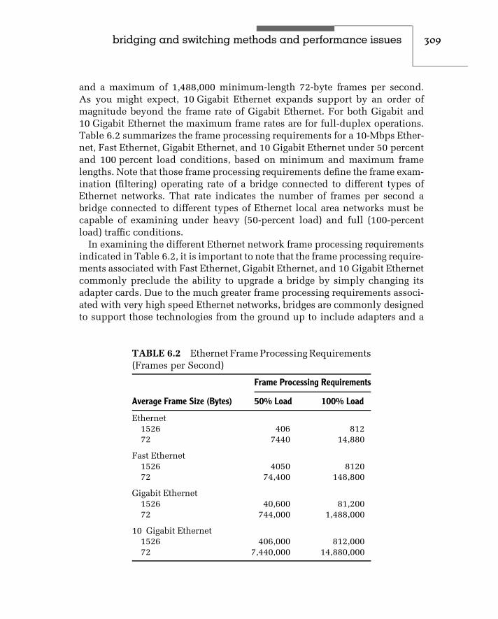
bridging and switching methods and performance issues 309
and a maximum of 1,488,000 minimum-length 72-byte frames per second.As you might expect, 10 Gigabit Ethernet expands support by an order ofmagnitude beyond the frame rate of Gigabit Ethernet. For both Gigabit and10 Gigabit Ethernet the maximum frame rates are for full-duplex operations.Table 6.2 summarizes the frame processing requirements for a 10-Mbps Ether-net, Fast Ethernet, Gigabit Ethernet, and 10 Gigabit Ethernet under 50 percentand 100 percent load conditions, based on minimum and maximum framelengths. Note that those frame processing requirements define the frame exam-ination (filtering) operating rate of a bridge connected to different types ofEthernet networks. That rate indicates the number of frames per second abridge connected to different types of Ethernet local area networks must becapable of examining under heavy (50-percent load) and full (100-percentload) traffic conditions.
In examining the different Ethernet network frame processing requirementsindicated in Table 6.2, it is important to note that the frame processing require-ments associated with Fast Ethernet, Gigabit Ethernet, and 10 Gigabit Ethernetcommonly preclude the ability to upgrade a bridge by simply changing itsadapter cards. Due to the much greater frame processing requirements associ-ated with very high speed Ethernet networks, bridges are commonly designedto support those technologies from the ground up to include adapters and a
TABLE 6.2 Ethernet Frame Processing Requirements(Frames per Second)
Frame Processing Requirements
Average Frame Size (Bytes) 50% Load 100% Load
Ethernet1526 406 81272 7440 14,880
Fast Ethernet1526 4050 812072 74,400 148,800
Gigabit Ethernet1526 40,600 81,20072 744,000 1,488,000
10 Gigabit Ethernet1526 406,000 812,00072 7,440,000 14,880,000

310 c h a p t e r s i x
central processor to support the additional frame processing associated withtheir higher operating rate.
We can extend our analysis of Ethernet frames by considering the framerate supported by different link speeds. For example, let us consider a pair ofremote bridges connected by a 9.6-Kbps line. The time per frame for a 72-byteframe at 9.6 Kbps is:
9.6 × 10⁻⁶ + 72 × 8 × 0.0001041 s/bit or 0.0599712 seconds per frame
Thus, in one second the number of frames is 1/.0599712, or 16.67 frames persecond. Table 6.3 compares the frame-per-second rate supported by differentlink speeds for minimum- and maximum-size Ethernet frames. As expected,the frame transmission rate supported by a 10-Mbps link for minimum- andmaximum-size frames is exactly the same as the frame processing requirementsunder 100 percent loading for a 10-Mbps Ethernet LAN, as indicated inTable 6.2.
In examining Table 6.3, note that the entries in this table do not considerthe effect of the overhead of a protocol used to transport frames betweentwo networks. You should therefore decrease the frame-per-second rate byapproximately 20 percent for all link speeds through 1.536 Mbps. The reasonthe 10-Mbps rate should not be adjusted is that it represents a local 10-Mbps Ethernet bridge connection that does not require the use of a widearea network protocol to transport frames. Also note that the link speed of1.536 Mbps represents a T1 transmission facility that operates at 1.544 Mbps.However, since the framing bits on a T1 circuit use 8 Kbps, the effective linespeed available for the transmission of data is 1.536 Mbps.
TABLE 6.3 Link Speed versus Frame Rate
Frames per Second
Link Speed Minimum Maximum
9.6 Kbps 16.67 0.79
19.2 Kbps 33.38 1.58
56.0 Kbps 97.44 4.60
64.0 Kbps 111.17 5.25
1.536 Mbps 2815.31 136.34
10.0 Mbps 14,880.00 812.00

bridging and switching methods and performance issues 311
Predicting Throughput
Until now, we have assumed that the operating rate of each LAN linkedby a bridge is the same. However, in many organizations this may notbe true, because LANs are implemented at different times using differenttechnologies. Thus, accounting may be using a 10-Mbps LAN, while thepersonnel department might be using a 100-Mbps LAN.
Suppose we wanted to interconnect the two LANs via the use of a multi-media bridge. To predict throughput between LANs, let us use the networkconfiguration illustrated in Figure 6.14. Here, the operating rate of LAN A isassumed to be R1 bps, while the operating rate of LAN B is assumed to beR2 bps.
In one second, R1 bits can be transferred on LAN A and R2 bits can betransferred on LAN B. Similarly, it takes 1/R1 seconds to transfer one bit onLAN A and 1/R2 seconds to transfer one bit on LAN B. So, to transfer onebit across the bridge from LAN A to LAN B, ignoring the transfer time atthe bridge:
1RT
= 1R1
+ 1R2
orRT = 1
(1/R1) + (1/R2)
We computed that a 10-Mbps Ethernet would support a maximum transfer of812 maximum-sized frames per second. If we assume that the second LANoperating at 100 Mbps is also an Ethernet, we would compute its transfer rateto be approximately 8120 maximum-sized frames per second. The throughputin frames per second would then become:
RT = 1(1/812) + (1/8120)
= 738 frames per second
Knowing the transfer rate between LANs can help us answer many commonquestions. It can also provide us with a mechanism for determining whether
LAN A LAN BR1 R2
Bridge
Figure 6.14 Linking LANs with different operating rates. When LANs withdifferent operating rates (R1 and R2) are connected via a bridge, access of filesacross the bridge may result in an unacceptable level of performance.

312 c h a p t e r s i x
we should alter the location of application programs on different servers. Forexample, suppose that a program located on a server on LAN B suddenlybecame popular for use by workstations on LAN A. If the program required1024 K of storage, we could estimate the minimum transfer time requiredto load that program and, depending on the results of our calculation, wemight want to move the program onto a server on LAN A. For this example,the data transfer rate would be 738 frames/second × 1500 bytes/frame or1,107,000 bytes per second. Dividing the data to be transferred by the datatransfer rate, we obtain:
1024 Kbytes × 1024 bytes/k1,107,000 bytes/seconds
= .95 seconds
The preceding computation represents a best-case scenario, in which the useof each network is limited to the user on LAN A loading a program from aserver on LAN B. In reality, the average number of users using the resourcesof each network must be used to adjust the values of R1 and R2. For example,suppose that through monitoring you determined that the average number ofactive users on LAN A was 5 and on LAN B was 10. In that case, you wouldadjust the value of R1 by dividing 812 by 5 to obtain 162.4 and adjust thevalue of R2 by dividing 8120 by 10 to obtain 812. You would then use the newvalues of R1 and R2 to obtain the average value of RT , based on the fact thatthe program loading operation would be performed concurrently with otheroperations on each network. Thus, you would compute RT as follows:
RT = 1(1/162.5) + (1/812)
= 135.4 frames per second
6.4 LAN Switches
The incorporation of microprocessor technology into hubs can be consideredas the first step in the development of switching hubs, which are now morecommonly referred to as LAN switches. Through additional programming,the microprocessor could examine the destination address of each frame;however, switching capability required the addition of a switching fabricdesign into the hub. Once this was accomplished, it became possible to usethe microprocessor to read the destination address of each frame and initiatea switching action based upon data stored in the hub’s memory, whichassociates destination frame addresses with hub ports.

bridging and switching methods and performance issues 313
There are several basic types of LAN switches, with the major differencebetween each type resulting from the layer in the ISO Reference Model whereswitching occurs. A layer 2 switch looks into each frame to determine thedestination MAC address while a layer 3 switch looks further into the frame todetermine the destination network address. Similarly, a layer 4 switch lookseven further into each frame to focus upon the transport layer header. Depend-ing upon the software that supports switch operations a layer 4 switch maybe programmed to make switching decisions based upon two or more criteria,such as destination IP address and port number. Thus, a layer 2 switch oper-ates at the MAC layer and can be considered to represent a sophisticated bridgewhile a layer 3 switch resembles a router. In comparison, a layer 4 switch thatuses multiple metrics in determining where to forward frames could functionas a traffic load balancer. Layer 2, layer 3, and layer 4 operations will becovered as we examine the operation and use of LAN switches.
In this section we will first examine the rationale for LAN switches by notingthe bottlenecks associated with conventional and intelligent hubs as networktraffic grows. Once this is accomplished, we will focus upon the operationand usage of different types of LAN switches.
Rationale
The earliest types of Ethernet LANs were designed to use coaxial cableconfigured using a bus topology. The development of the hub-based 10BASE-T local area network offered a number of networking advantages over the useof coaxial cable. Some of those advantages included the use of twisted-paircable, which is easier to use and less expensive than coaxial cable, and theability to reconfigure, troubleshoot, and isolate network problems. By simplymoving a cable connection from one port to another network, administratorscan easily adjust the usage of a hub or interconnect hubs to form a new networkstructure. The connection of test equipment to a hub, either to a free port or bytemporarily removing an existing network user, could be accomplished mucheasier than with a coaxial-based network. Recognizing these advantages, hubmanufacturers added microprocessors to their hubs, which resulted in theintroduction of a first generation of intelligent Ethernet hubs.
The first generation of intelligent hubs used the capability of a built-in microprocessor to provide a number of network management functionsnetwork administrators could use to better control the operation and usage oftheir network. Those functions typically include tracking the network usagelevel and providing summary statistics concerning the transmission of framesby different workstations, as well as providing the network administrator with

314 c h a p t e r s i x
the ability to segment the LAN by entering special commands recognized bythe hub.
BottlenecksBoth conventional and first-generation intelligent hubs simply duplicateframes and forward them to all nodes attached to the hub. This restrictsthe flow of data to one workstation at a time, since collisions occur whentwo or more workstations attempt to gain access to the media at thesame time.
Conventional hubs, to include the first generation of intelligent hubs, createnetwork bottlenecks, because all network traffic flows through a shared back-plane. This results in every workstation connected to the hub competing for aslice of the backplane’s bandwidth. For example, consider the hub illustratedin Figure 6.15, in which up to seven workstations and a file server contendfor access to the network. Since only one device can transmit at any point intime, the average slice of bandwidth that each device receives is 1.25 Mbps(10 Mbps/8). The actual data transfer capability is less, since attempts by twoor more workstations to simultaneously transmit can result in collisions thatcause jam signals to be placed on the network, precluding other workstationsfrom transmitting data during the duration of those signals. As more usersare added to a network through the interconnection of hubs, network per-formance will continue to decrease as the potential for congestion increases.Thus, manufacturers of Ethernet products, as well as network administra-tors, focused their efforts upon developing different tools and techniques toalleviate network congestion.
Congestion-Avoidance OptionsThere are several techniques you can consider to alleviate network congestion.Those techniques include splitting a network into two, with each segment
WS WS
Conventional hub
Server
Figure 6.15 When using a conven-tional hub, congestion occurs whenseveral workstations vie for access toa server.

bridging and switching methods and performance issues 315
connected to a separate server port, using bridges and dual servers, employinga router to develop a collapsed backbone network linking multiple networksegments, or using one or more intelligent switches.
Network Segmentation
One of the earliest methods used to alleviate network congestion was obtainedthrough the use of a server with an internal bridging capability. Splitting thenetwork infrastructure into two and connecting each resulting segment to anNIC installed in a server provides the capability to reduce traffic on each seg-ment, in comparison to traffic previously carried on a nonsegmented network.
Figure 6.16 illustrates the segmentation of a network into two on one server.NetWare, as well as other LAN operating systems, includes a capability tomove packets between cable segments. This enables users on each segmentto transmit and receive information from users on other segments, as well asmaintain access to a common server. If server usage is low but network usageis high, this method of network subdivision represents a cost-effective methodfor reducing the effect of network congestion upon LAN performance.
In examining Figure 6.16, note that a workstation on each network segmentcan simultaneously transmit data to the server or receive data from theserver. Thus, segmentation not only reduces network congestion, but inaddition can double throughput if the server is capable of supporting sustainedtransmission to or receiving data from workstations on both segments.
Bridging
The major problem associated with the use of a server for network segmen-tation is the fact that it must perform internal bridging in addition to itsfile server operations. This usually limits the ability of the server to supportnetwork segments with a large number of workstations. In addition, the work-stations on the connected segments still contend for the services of a commonserver. Thus, the use of a stand-alone bridge is usually the next step to
Server Figure 6.16 Network segmentationusing a common server. Throughthe use of a file server that canmove packets between segments,you obtain the ability to subdividea network.

316 c h a p t e r s i x
consider when the level of network usage adversely affects LAN performance,and segmentation through the use of a file server is not a viable option.
Figure 6.17 illustrates the use of a bridge for network segmentation. Althoughthe segmentation shown in Figure 6.17 is similar to the segmentation shownin Figure 6.16, there are several distinct differences between the two meth-ods. First, the stand-alone bridge requires file servers to be located on oneor more network segments. Secondly, since a stand-alone bridge is per-forming the required bridging functions, more workstations can be placedon each network segment than when a file server performs bridging opera-tions. Workstations on each segment can simultaneously access the server oneach segment, permitting network throughput to double when such traffic islocalized to each segment.
Using a Router
Although primarily thought of as a mechanism to interconnect geographicallydispersed networks, routers can be used as switching devices to interconnectnetwork segments located within one geographical area, such as a buildingor campus. The networking architecture associated with the use of a routerin this manner is referred to as a collapsed backbone, since the older bus-structured Ethernet LAN is replaced by LAN segments that communicatewith one another through the router. Until 1994, the primary device used inthe center of a collapsed backbone network was a router. Since then, LANswitches have gradually taken over the role of routers for reasons we willdiscuss later in this chapter.
To otherhubs
To otherhubs
Bridge
Ser-ver
Ser-ver
Figure 6.17 Using a bridge for network segmentation. The use of a bridgeand one or more servers on each interconnected segment can significantlyincrease network capacity by localizing more traffic on each segment.

bridging and switching methods and performance issues 317
Router
Server
Server
Ser-ver
Ser-ver
Figure 6.18 Collapsed router-based backbone. A collapsed backbone topol-ogy based upon the use of a router enables servers to be distributed basedupon network access requirements.
Figure 6.18 illustrates a collapsed backbone formed through the use of arouter. Note that you can locate servers on network segments for which serveraccess is limited to workstations on the segment, and connect servers that areaccessed by workstations on two or more segments to separate router ports.Thus, a router provides you with the ability to distribute network traffic basedupon server access requirements. In addition, the construction of a collapsedbackbone offers other benefits over distributed networks. Those advantagesinclude the centralization of complexity and economy of operations. Ratherthan dispersing routers, locating a single router near a network technicalcontrol center can make network management easier. Then, if a routingproblem arises, you may not have to send a technician to every location wherehubs and servers are installed, since router management software may be ableto pinpoint the problem. Since one router may be able to replace a number ofless capable devices, you may also obtain some economic benefits from theuse of a single router.
Three additional benefits associated with the use of a router for creating acollapsed backbone network are security, protocol support, and the controlof broadcast traffic. Many routers have a sophisticated filtering capability,permitting you to program templates that enable only predefined applicationsfrom predefined network users to access other network segments or serversconnected to the router. Concerning protocol support, many routers can

318 c h a p t e r s i x
support multiprotocol transmission. Thus, you could connect a router port toa mainframe and pass SNA traffic between the mainframe and workstationson different network segments, as well as switching other protocol trafficbetween workstations and different types of servers. Since the use of a routerresults in a hierarchical network structure where frames are transported basedupon network addresses, this provides the ability to restrict broadcast trafficgenerated on one segment to that segment. Thus, service advertisementscommonly generated by different types of servers can be localized to thesegment where they are located instead of flowing onto other segments wherethey would consume bandwidth.
Although the advantages associated with the use of routers to create acollapsed backbone are considerable, their use has several disadvantages.Those disadvantages include the complexity and cost of routers, as well asthe latency or delay time associated with moving packets from one networksegment to another segment. Concerning router latency, although all deviceshave a degree of latency, the delay associated with routers greatly exceedsthat of bridges. The reason for this is the fact that routers operate at thenetwork layer while bridges operate at the data link layer. This means that abridge can inspect the beginning of each frame to determine its destination. Incomparison, a router must look into each frame to determine the destinationnetwork address. Thus, the processing rate of a router is generally 50 to75 percent of the processing rate of a bridge.
Another problem associated with the use of routers is the eggs in one basketsyndrome, since the failure of the router results in the inability of manynetwork users to access servers or send messages to users on other networksegments. The latter problem has been addressed by router manufacturersthrough redundant logic and power supplies, as well as the use of modularcomponents that can be easily swapped out without bringing down the routerwhen a component failure occurs. Although the latter problem is applicable toLAN switches, this device addresses some of the problems associated with theuse of routers, as well as — through improved functionality — permits LANswitches to provide an enhanced level of overall network performance. Thus,let’s focus our attention upon the operation and use of LAN switches in theremainder of this chapter.
LAN Switch Operations
LAN switches can be categorized in three main ways — by their method ofoperation, their support of single or multiple addresses per port, and the layerin the ISO Reference Model where switching occurs. The method of operation

bridging and switching methods and performance issues 319
is commonly referred to as the switching technique, while the address-per-portsupport is normally referred to as the switching method.
The third main way of categorizing a LAN switch is based upon the type ofaddress used as a switching decision criteria — data link layer MAC addresses,network layer network addresses or transport layer port number. Since LANswitches that support layer 3 switching actually represent a switch with abuilt-in routing capability, we will discuss layer 3 switches as a separate entity.We will also examine how a layer 4 LAN switch can function as an applicationdistributor by making switching decisions based upon the port number withinthe transport header. Thus, we will first examine layer 2 switching hubs beforefocusing our attention upon layer 3 and layer 4 switches.
Layer 2 Switching
A switch that operates at the data link layer is a multiport bridge that readsMAC destination addresses and uses those addresses as a decision criterionfor determining where to switch each frame. When operating at the datalink layer, a LAN switch provides several distinct advantages over the use ofconventional and intelligent hubs. First, a LAN switch does not transmit orregenerate data onto every port. Instead, unicast data flow is restricted to arouting from one port to a second port. This precludes a network user fromoperating a monitor and observing the flow of data on the network. Hence,LAN switches, although not necessarily secure devices, provide a more secureenvironment than a shared Ethernet LAN.
A second advantage of LAN switches is their ability to support simultaneouscommunication sessions. For example, consider a simple four-port LANswitch with port numbers 1, 2, 3, and 4. If a user on port 1 is switched toa server on port 3, and another user on port 2 is switched to a server onport 4, you obtain two very short-duration, simultaneous communicationssessions. Thus, in this example, bandwidth is double that of a conventionalhub. If the LAN switch supports only 10BASE-T operating rates, the four-portswitch provides a maximum of two simultaneous cross-connections, doublingpotential bandwidth to 20 Mbps. As we will note later in this chapter, manyLAN switches incorporate full-duplex, Fast Ethernet, Gigabit Ethernet, andeven 10 Gigabit Ethernet technology, providing bandwidth many orders ofmagnitude beyond that obtainable from the use of a conventional hub.
Switching Techniques There are three switching techniques used by LANswitches — cross-point, also referred to as cut-through or on the fly, store-and-forward, and a hybrid method which alternates between the first two methods,
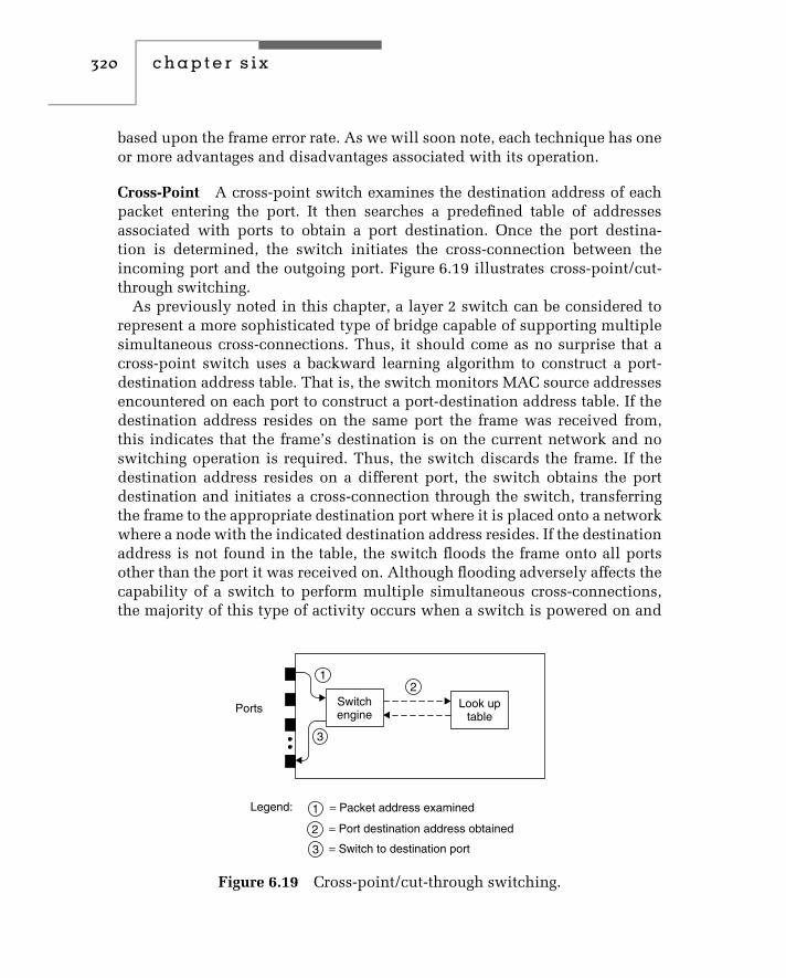
320 c h a p t e r s i x
based upon the frame error rate. As we will soon note, each technique has oneor more advantages and disadvantages associated with its operation.
Cross-Point A cross-point switch examines the destination address of eachpacket entering the port. It then searches a predefined table of addressesassociated with ports to obtain a port destination. Once the port destina-tion is determined, the switch initiates the cross-connection between theincoming port and the outgoing port. Figure 6.19 illustrates cross-point/cut-through switching.
As previously noted in this chapter, a layer 2 switch can be considered torepresent a more sophisticated type of bridge capable of supporting multiplesimultaneous cross-connections. Thus, it should come as no surprise that across-point switch uses a backward learning algorithm to construct a port-destination address table. That is, the switch monitors MAC source addressesencountered on each port to construct a port-destination address table. If thedestination address resides on the same port the frame was received from,this indicates that the frame’s destination is on the current network and noswitching operation is required. Thus, the switch discards the frame. If thedestination address resides on a different port, the switch obtains the portdestination and initiates a cross-connection through the switch, transferringthe frame to the appropriate destination port where it is placed onto a networkwhere a node with the indicated destination address resides. If the destinationaddress is not found in the table, the switch floods the frame onto all portsother than the port it was received on. Although flooding adversely affects thecapability of a switch to perform multiple simultaneous cross-connections,the majority of this type of activity occurs when a switch is powered on and
1
1
2
2
3
3
Look uptable
Switchengine
Legend:
Ports
= Packet address examined
= Port destination address obtained
= Switch to destination port
Figure 6.19 Cross-point/cut-through switching.

bridging and switching methods and performance issues 321
its port-address table is empty. Thereafter, flooding occurs periodically afteran entry is purged from the table due to aging and a new request to a purgeddestination occurs, a new station becomes a recipient of traffic, or when abroadcast address is encountered.
Cross-point switching minimizes the delay or latency associated with plac-ing a packet received on one port onto another port. Since the switchingdecision is made once the destination address is read, this means the fullpacket is not examined. Thus, a cross-point switch cannot perform errorchecking on a packet. This limitation does not represent a problem for mostnetworks due to extremely low error rates on local area networks. However,when errored packets are encountered, they are passed from one networksegment to another. This results in an unnecessary increase in network use onthe destination segment, as a store-and-forward switch would simply discardpackets containing one or more bit errors.
Latency Considerations A cross-point switching method only requires asmall portion of a frame to be stored until it is able to read the destinationaddress, perform its table lookup operation, and initiate switching to anappropriate output port. Due to this, latency is minimized.
Latency functions as a brake on two-way frame exchanges. For example, in aclient/server environment the transmission of a frame by a workstation resultsin a server response. Thus, the minimum wait time is 2 ∗ latency for eachclient-server exchange, lowering the effective throughput of the switch. Wecan compute the minimum amount of latency associated with a cross-pointswitch as follows. At a minimum, the switch must read 14 bytes (8 bytes forthe preamble and 6 bytes for the destination address) before being able toinitiate a search of its port-destination address table. At 10 Mbps we obtain:
9.6 µs + 14 bytes ∗ 8 bits/byte ∗ 100 ns/bit
or 9.6 × 10⁻⁶ + 112 ∗ 100 ∗ 10−9
or 20.8 ∗ 10−6 seconds
Here 9.6 µs represents the Ethernet interframe gap at an operating rate of10 Mbps, while 100 ns/bit represents the bit duration of a 10-Mbps EthernetLAN. Thus, the minimum one-way latency not counting switch overheadof a cut-through layer 2 switch is 20.8 ∗ 10−6 seconds, while the round-tripminimum latency would be twice that duration.
At 100 Mbps the interframe gap would be reduced to .96 µs, while the bitduration would be 10 ns. Thus, at 100 Mbps the minimum one-way latency

322 c h a p t e r s i x
for a cross-point switch becomes:
.96 × 10−6 + 112 ∗ 10 ∗ 10−9
or 2.08 ∗ 10−6 seconds
For Gigabit Ethernet the minimum one-way latency would be further reducedby an order of magnitude to .208 ∗ 10−6 seconds.
Store-and-Forward A store-and-forward LAN switch stores the full incom-ing packet in a buffer. This enables the switch to perform a CRC check todetermine if the received packet is error-free. If it is, the switch uses thedestination address of the packet to perform a table lookup to obtain thedestination port address. Once that address is obtained, the switch performs across-connect operation and forwards the packet to its destination. Otherwise,the frame is considered to have one or more bits in error and will be discarded.Besides checking the CRC a store-and-forward switch will examine the entireframe. This enables other errors, such as runts and extended lengths (giant)frames to be caught and sent to the great bit bucket in the sky instead ofbeing forwarded.
The storage of frames by a store-and-forward switch permits filteringagainst various frame fields to occur. Although a few manufacturers of store-and-forward LAN switches support different types of filtering, the primaryadvantage advertised by such manufacturers is data integrity and the ability toperform translation switching, such as switching a frame between an Ethernetnetwork and a Token-Ring network. Since the translation process is extremelydifficult to accomplish on the fly due to the number of conversions of framedata, most switch vendors first store the frame, resulting in store-and-forwardswitches supporting translation between different types of connected net-works. Concerning the data integrity capability of store-and-forward switches,whether or not this is actually an advantage depends upon how you view theadditional latency introduced by the storage of a full frame in memory as wellas the necessity for error checking. Concerning the latter, switches shouldoperate error-free, so a store-and-forward switch only removes network errors,which should be negligible to start with.
When a switch removes an errored frame, the originator will retransmit theframe after a period of time. Since an errored frame arriving at its destinationnetwork address is also discarded, many persons question the necessity oferror checking by a store-and-forward switch. However, filtering capability, ifoffered, may be far more useful as you could use this capability, for example,to route protocols carried in frames to destination ports far easier than by

bridging and switching methods and performance issues 323
frame destination address. This is especially true if you have hundreds orthousands of devices connected to a large switch. You might set up twoor three filters instead of entering a large number of destination addressesinto the switch. When a switch performs filtering of protocols, it reallybecomes a router. This is because it is now operating at layer 3 of the OSIReference Model.
Figure 6.20 illustrates the operation of a store-and-forward switch. Notethat a common switch design is to use shared buffer memory to store entireframes, which increases the latency associated with this type of switch. Sincethe minimum length of an Ethernet frame is 72 bytes, then the minimumone-way delay or latency for a 10 mbps Ethernet operation, not countingthe switch overhead associated with the lookup table and switching fabricoperation, becomes:
9.6 µsec + 72 bytes ∗ 8 bits/byte ∗ 100 ns/bit
or 9.6 ∗ 10−6 + 576 ∗ 100 ∗ 10−9
or 67.2 ∗ 10−6 seconds
Once again, 9.6 µs represents the 10-Mbps Ethernet interframe gap, while100 ns/bit is the bit duration of a 10-Mbps Ethernet LAN. Thus, theminimum one-way latency of a store-and-forward Ethernet LAN switch is.0000672 seconds, while a round-trip minimum latency is twice that duration.For a maximum-length Ethernet frame with a data field of 1500 bytes, the
1
1
2
2
4
3
3
Switchengine
Look uptable
SharedRAM
Legend:
Ports
= Packet address read as packet enters RAM
= Full packet enters RAM; CRC computed
4 = Packet forwarded from RAM to destination port
= Destination port obtained
Figure 6.20 Store-and-forward switching.

324 c h a p t e r s i x
frame length becomes 1526 bytes. Thus, the one-way maximum latency at10 Mbps becomes:
9.6 µs + 1526 bytes ∗ 8 bits/byte ∗ 100 ns/bit
or 9.6 ∗ 10−6 + 12208 ∗ 100 ∗ 10−9
or .0123404 seconds
At a 100 Mbps operating rate associated with Fast Ethernet the interframe gapis reduced to .96 µs while the bit duration becomes 10 ns. Thus, the one waylatency for a minimum length frame becomes:
.96 ∗ 10−6 + 576 ∗ 10 ∗ 10 10−9
or 6.72 ∗ 10−6 seconds
Similarly, for a maximum length frame the one way latency at 100Mbps becomes:
.96 ∗ 10−6 + 12208 ∗ 10−9
or .00123 seconds
At a Gigabit Ethernet data rate of 1 Gbps both the interframe gap and bitduration are further reduced by an order of magnitude. This results in the oneway latency for a minimum length frame becoming .672 ∗ 10−6 seconds whilethe delay for a maximum length frame becomes:
1.23 ∗ 10−4 seconds
Table 6.4 summarizes the minimum latency for cut-through and store-and-forward switches operating at 10 and 100 Mbps and 1 Gbps. You can usethe entries in this table to determine the potential effect upon differentapplications, such as real-time video, and select a switch that can satisfyorganizational requirements.
Hybrid A hybrid switch supports both cut-through and store-and-forwardswitching, selecting the switching method based upon monitoring the errorrate encountered by reading the CRC at the end of each frame and comparingits value with a computed CRC performed on the fly on the fields protectedby the CRC. Initially the switch might set each port to a cut-through modeof operation. If too many bad frames are noted occurring on the port theswitch will automatically set the frame processing mode to store-and-forward,

bridging and switching methods and performance issues 325
permitting the CRC comparison to be performed before the frame beingforwarded. This permits frames in error to be discarded without having thempass through the switch. Since the switch, no pun intended, between cut-through and store-and-forward modes of operation occurs adaptively, anotherterm used to reference the operation of this type of switch is adaptive.
The major advantages of a hybrid switch are that it provides minimallatency when error rates are low and discards frames by adapting to a store-and-forward switching method so it can discard errored frames when the frameerror rate rises. From an economic perspective, the hybrid switch can logicallybe expected to cost a bit more than a cut-through or store-and-forward switchas its software development effort is a bit more comprehensive. However, dueto the competitive market for communications products upon occasion itsprice may be reduced below competitive switch technologies.
Switching Methods LAN switches can be classified with respect to theirsupport of single or multiple addresses per port. The support of a singleaddress per port is referred to as port-based switching, while the support ofmultiple addresses per port is referred to as segment-based switching.
Port-Based Switching A port-based LAN switch can be considered to operatesimilar to an n × n matrix switch, reading the destination address of incomingframes from a single device connected to the port and using that addressthrough a table lookup process to initiate a cross-connect to a destination port.
Figure 6.21 illustrates an example of port-based switching. Since eachconnected node is isolated from other nodes except when simultaneously
TABLE 6.4 Cut-through and Store-and-forward Minimum SwitchLatency
Latency (seconds)
Switch/Operating Rate Minimum Length Frame Minimum Length Frame
Cut-through10 Mbps 20.8 ∗ 10−6 20.8 ∗ 10−6
100 Mbps 2.08 ∗ 10−6 2.08 ∗ 10−6
1 Gbps .208 ∗ 10−6 .208 ∗ 10−6
Store-and-forward10 Mbps 67.2 ∗ 10−6 1.2304 ∗ 10−2
100 Mbps 6.72 ∗ 10−6 .12304 ∗ 10−2
1 Gbps .672 ∗ 10−6 .012304 ∗ 10−2

326 c h a p t e r s i x
Server1
Server2
ServerN
UserN
User1
Portswitching
Figure 6.21 Port-based switching. Inport-based switching only a singleaddress per port is supported,restricting switching to one deviceper port.
contending for access to the same destination port, the resulting networkthroughput can be considerably higher than a shared Ethernet network. Forexample, user 1 could communicate with server 1, user 2 with server 2, and soon, all simultaneously. In this best case example, with n users and n servers,the operating rate through the switch becomes n × 10 Mbps, or n times theoperating rate of a conventional Ethernet network.
It is important to compare the maximum potential throughput through aswitch with its rated backplane speed. If the maximum potential throughputis less than the rated backplane speed, the switch will not cause delays basedupon the traffic being routed through the device. For example, consider a64-port switch that has a backplane speed of 400 Mbps. If the maximumport rate is 10 Mbps, then the maximum throughput assuming 32 activecross-connections were simultaneously established becomes 320 Mbps. Inthis example the switch has a backplane transfer capability sufficient tohandle the worst-case data transfer scenario. Now let’s assume that themaximum backplane data transfer capability was 200 Mbps. This wouldreduce the maximum number of simultaneous cross-connections capable ofbeing serviced to 20 instead of 32 and adversely affect switch performanceunder certain operational conditions.
Since a port-based switch only has to store one address per port, search timesare minimized. When combined with a pass-through or cut-through switchingtechnique, this type of switch results in a minimal latency to include theoverhead of the switch in determining the destination port of a frame.
Segment-Based Switching A segment-based switch permits switched con-nectivity between multiple LAN segments, by supporting multiple addressesper port. The key difference between a segment-based switch and a port-basedswitch is in their ability to support multiple addresses per port. A port-based

bridging and switching methods and performance issues 327
layer 2 switch only supports one MAC address per port. In comparison, asegment-based layer 2 switch supports multiple addresses per port, enablingit to support the direct connection of a single workstation or server as well asthe connection of a segment to each port on the switch.
Figure 6.22 illustrates an example of a segment-based switch. Note thatports that support the connection of a segment must support switching formultiple MAC addresses. In examining the segment-based switching exampleillustrated in Figure 6.22, also note that workstations on each segment contendfor access to n servers. Since a group of users is connected to the switch viaa conventional hub, throughput is limited by the conventional hubs. In thisexample, two hubs would limit throughput of the network to 20 Mbps if auser on each segment accessed a different server. In comparison, a port-basedswitch can provide a higher throughput, since each network user is directlyconnected to a port on the switch. The primary advantage of a segment-basedLAN switch is cost, since a few ports can be used to support network segmentscontaining a large number of LAN users.
Switching Processor The construction of intelligent switches varies bothbetween manufacturers as well as within some vendor product lines. Mostswitches are based upon the use of either reduced instruction set com-puter (RISC) microprocessors or application-specific integrated circuit (ASIC)chips, while a few products use conventional complex instruction set com-puter (CISC) microprocessors.
Although there are a large number of arguable advantages and disadvan-tages associated with each architecture from the standpoint of the switch
Segmentswitching
hub
Conventionalhub
Conventionalhub
Server1
ServerN
User1
User1
UserN
UserN
Figure 6.22 Segment-based switching. A segment-based switching techniquerequires each port to support multiple MAC addresses.

328 c h a p t e r s i x
manufacturer that are beyond the scope of this book, there are also some keyconsiderations that warrant discussion with respect to evolving technology,such as virtual LANs. Both RISC and CISC architectures enable switches tobe programmed to make forwarding decisions based upon either the data linklayer or network layer address information. In addition, when there is a needto modify the switch such as to enable it to support a vLAN standard, thisarchitecture is easily upgradable.
In comparison to RISC- and CISC-based switches, an ASIC-based device rep-resents the use of custom-designed chips to perform specific switch functionsin hardware. Although ASIC-based switches are faster than RISC- and CISC-based switches, there is no easy way to upgrade this type of switch. Instead,the vendor will have to design and manufacture new chips and install thehardware upgrade in the switch.
Today most switches use an ASIC architecture, as its speed enables thesupport of cut-through switching. While ASIC-based switches provide thespeed necessary to minimize latency, readers should carefully check vendorupgrade support as support for adding load balancing and other functions toa LAN switch can be expected to require modifications to existing switches.
Now that we have an appreciation for the general operation and use of LANswitches, let’s obtain an appreciation for the high-speed operation of switchports, which enables dissimilar types of networks to be connected and whichcan result in data flow compatibility problems along with methods used toalleviate such problems.
High-Speed Port Operations There are several types of high-speed portconnections switches may support. Those high-speed connections include100-Mbps Fast Ethernet, 1-Gbps and 10-Gbps Gigabit Ethernet, 100-MbpsFDDI, 155-Mbps ATM, full-duplex Ethernet and Token-Ring, and fat pipes,with the latter referencing a grouping of ports treated as a transmission entity.Another common name used in place of the term fat pipe is trunk group. Themost common use of one or more high-speed connections on a switch is tosupport highly used devices, such as network servers and printers as well asfor obtaining a backbone LAN connection capability. Figure 6.23 illustratesthe use of an Ethernet switch, with two 100BASE-T Fast Ethernet adaptersbuilt into the switch to provide a high-speed connection from the switch toeach server. Through the use of high-speed connections the cross-connectiontime from a server to client when the server responds to a client query isminimized. Since most client queries result in server responses containingmany multiples of characters in the client query, this allows the server torespond to more queries per unit of time. Thus, the high-speed connection

bridging and switching methods and performance issues 329
Server
100BASE-Tports
10BASE-Tports
Server
Figure 6.23 Using high-speed connec-tions to servers.
can enhance client/server response times through a switch. In examiningFigure 6.23, let’s assume a small query results in the server responding bytransmitting the contents of a large file back to the client. If data flowsinto the switch at 100 Mbps and flows from the switch to the client at10 Mbps, any buffer area in the switch used to provide temporary storage forspeed incompatibilities between ports will rapidly be filled and eventuallyoverflow, resulting in the loss of frames which, when compensated for byretransmission, compounds the problem. Thus, a mechanism is required toregulate the flow of data into and out of switch ports. That mechanism isknown as flow control, and specific methods used to implement flow controlwill be covered later in this chapter when we discuss switch features.
Thus for now we can note that the LAN switch is a highly versatile devicethat may support single or multiple devices per port and whose operation canvary based upon its architecture. By providing the capability for supportingmultiple simultaneous cross-connections, the LAN switch can significantlyincrease network bandwidth, and its ability to support high-speed networkconnections enhances its versatility. Now that we have a basic appreciationfor the operational characteristics of generic Ethernet LAN switches, we canuse that information as a base and focus our attention upon the operation ofEthernet switches.
Switch Operations Although features incorporated into Ethernet switchesconsiderably differ between vendors as well as within vendor product lines,

330 c h a p t e r s i x
upon occasion we can categorize this communications device by the operatingrate of the ports they support. Doing so results in six basic types of Ethernetswitches which are listed in Table 6.5. Switches that are restricted to operatingat a relatively low data rate are commonly used for departmental operations,while switches that support a mixed data rate are commonly used in a tierednetwork structure at a higher layer in the tier than switches that operate at alow uniform data rate. Concerning the latter, when used in a tiered networkstructure the lower uniform operating rate switch is commonly used at thelower level in the tier. One item that warrants attention in Table 6.5 is thelast entry in the table. At the time this book was prepared 10 Gbps ports wererestricted to one or two per switch and it could be several years before aswitch is available with ports that all operate at 10 Gbps.
Multi-Tier Network Construction
Figure 6.24 illustrates the generic use of a two-tiered Ethernet switch–basednetwork, with the switch at the higher tier functioning as a backbone connec-tivity mechanism, which enables access to shared servers commonly knownas global servers by users across departmental boundaries, while switches inthe lower tier facilitate access to servers shared within a specific department.This hierarchical networking structure is commonly used with a higher-speedEthernet switch such as a Fast Ethernet or Gigabit Ethernet switch, or withother types of backbone switches, such as FDDI and ATM, as well as with othertypes of lower-tier switches. One common variation associated with the useof a tiered switch–based network is the placement of both departmental andglobal servers on an upper-tier switch. This placement allows all servers to becolocated in a common area for ease of access and control and is commonlyreferred to as a server farm. However, if an upper-tier switch should fail,
TABLE 6.5 Types of Ethernet Switches Basedupon Port Operating Rates
All ports operate at 10 Mbps.
Mixed 10-/100-Mbps port operation.
All ports operate at 100 Mbps.
Mixed 10-/100-/1000-Mbps port operation.
All ports operate at 1000 Mbps.
Mixed 10-/100-/1000/10000 Mbps port operation.

bridging and switching methods and performance issues 331
GS
DS
DS
GS
DS
GS
Switch
Switch Switch
Higher tier
Lower tier
Legend:
= Departmental server
= Global server
= Workstation
Figure 6.24 Generic construction of a two-tiered Ethernet switch–basednetwork.
access to all servers could be affected, representing a significant disadvantageof this design. A second major disadvantage is the fact that all traffic has tobe routed through at least two switches when a server farm is constructed.In comparison, when servers primarily used by departmental employees areconnected to a switch serving departmental users, most traffic remains localto the local switch at the bottom of the tier.
With the introduction of Gigabit Ethernet switches it becomes possible touse this type of switch in either a multitier architecture as previously shownin Figure 6.24 or as a star-based backbone. Concerning the latter, Figure 6.25illustrates the potential use of a Gigabit Ethernet switch that supports amixture of 100-Mbps and 1-Gbps ports. In this example the Gigabit Ethernetswitch is shown being used to support two fat pipes or trunk groups, withone trunk group consisting of four 100-Mbps ports, while the second group

332 c h a p t e r s i x
Enterpriseserver
Enterpriseserver
Fast ethernethub
Fast ethernethub
Fast ethernethub
1 Gbps
100 Mbps
Gigabit switch
Trunkgroup
400 Mbps
Departmentalserver
Departmentalserver
Trunk group200 Mbps
Figure 6.25 Using a Gigabit Ethernet switch as a star-based backbone switch.
consists of two 100-Mbps ports. To enable each grouping requires the use ofswitches from the same vendor since the establishment of fat pipes or trunkgroups is a proprietary feature and not yet standardized.
In examining Figure 6.25 note that enterprise servers are connected to theGigabit switch, while department servers are connected to 100-Mbps FastEthernet hubs. By connecting 10BASE-T LAN switches to Fast Ethernet hubsyou could extend the star into a star-tiered network structure.
6.5 Switch Basic ArchitectureRegardless of the operating rate of each port on an Ethernet switch, mostdevices are designed in a similar manner. That is, most switches consist of achassis into which a variety of cards are inserted, similar in many respects tothe installation of cards into the system expansion slots of personal computers.
ComponentsModular Ethernet switches that are scalable commonly support CPU, logic,matrix, and port cards.

bridging and switching methods and performance issues 333
CPU Card
The CPU card commonly manages the switch, identifies the types of LANsattached to switch ports, and performs self and directed switch tests.
Logic Module
The logic module is commonly responsible for comparing the destinationaddress of frames read on a port against a table of addresses it is responsiblefor maintaining, and instructing the matrix module to initiate a cross-barswitch once a comparison of addresses results in the selection of a destinationport address.
Matrix Module
The matrix module of a switch can be considered to represent a cross-barof wires from each port to each port as illustrated in Figure 6.26. Upon
1
Port
Port n
n
Figure 6.26 The key to the operation of a switch is a matrix modulewhich enables each port to be cross-connected to other ports. The matrixmodule of a switch with n ports can be considered to represent an n × nstar-wired backplane.

334 c h a p t e r s i x
receipt of an instruction from a logic module, the matrix module initiates across-connection between the source and destination port for the duration ofthe frame.
Port Module
The port module can be considered to represent a cluster of physical interfacesto which either individual stations or network segments are connected basedupon whether the switch supports single or multiple MAC addresses per port.Some port modules permit a mixture of port cards to be inserted, resultingin, as an example, 10 and 100 Mbps as well as full-duplex connections to besupported. In comparison, other port modules are only capable of supportingone type of LAN connection. In addition, there are significant differencesbetween vendor port modules concerning the number of ports supported.Some modules are limited to supporting two or four ports, while othermodules may support six, eight, or ten ports. It should be noted that manyswitches support other types of LAN port modules such as Token-Ring, FDDI,and even ATM.
Redundancy
In addition to the previously mentioned modules, most switches also supportsingle and redundant power supply modules and may also support redundantmatrix and logic modules. Figure 6.27 illustrates a typical Ethernet modularswitch chassis showing the installation of 11 modules to include five 8-portmodules to form a 40-port switch.
CPU
LOGIC
LOGIC
MATRIX
POWER
POWER
OPEN
OPEN
Figure 6.27 A typical Ethernet modular switch chassis containing a mixtureof port, CPU, logic, matrix, and power cards.
bridging and switching methods and performance issues 335
Switch Features
There are literally an ever expanding number of features being incorporatedinto Ethernet switches. Those features range from providing such basic func-tions as port and segment switching to methods developed by some vendorsto prevent erroneous frames from being transferred through the switch in acut-through mode of operation. In this section we will review 19 distinctswitch features, which are summarized in alphabetical order in Table 6.6.
The table of features presented was constructed not only to list featuresyou should note, but, in addition, as a mechanism to facilitate the evaluationof switches. That is, you can indicate your requirement for a particularfeature and then note whether or not that requirement can be satisfied bydifferent vendor products by replacing Vendor A and Vendor B by the namesof switches you are evaluating. By duplicating this table, you can extend thetwo rightmost columns to evaluate more than two products. As we examineeach feature listed in Table 6.6, our degree of exploration will be basedupon whether or not the feature was previously described. If the featurewas previously described in this chapter, we will limit our discussion toa brief review of the feature. Otherwise we will discuss its operation inconsiderable detail.
Address Table Size Support
The ability of a switch to correctly forward packets to their intended directiondepends upon the use of address tables. Similarly, the capability of a switchto support a defined number of workstations depends upon the number ofentries that can be placed in its address table. Thus, the address table sizecan be viewed as a constraint that affects the ability of a switch to supportnetwork devices.
There are two address table sizes you may have to consider — the numberof addresses supported per port and the number of addresses supported perswitch. The first address table constraint is only applicable for ports thatsupport the connection of network segments. In comparison, the total numberof addresses recognized per switch represents a constraint that affects theentire switch. Many Ethernet switches support up to 1024 addresses per portfor segment-based support. Such switches may only support a total of 8192addresses per switch. This means that a 16-port switch with 8 fully populatedsegments could not support the use of the 8 remaining ports as the switchwould run out of address table entries. Thus, it is important to consider thenumber of addresses supported per port and per switch as well as match suchdata against your anticipated requirements.

336 c h a p t e r s i x
TABLE 6.6 Ethernet Switch Features
Feature Requirement Vendor A Vendor B
Address table size supportAddresses/portAddresses/switch
Aging settings
ArchitectureASIC-basedCISC-basedRISC-based
Autonegotiation ports
Backplane transfer capacity
Error prevention
Fat pipe and trunk group
Filtering/forwarding rate supportFiltering rateForwarding rate
Flow controlBackpressureSoftware drivers802.3x flow controlNo control
Full-duplex port operation
Jabber control
Latency
Management
Mirrored port
Module insertion
Port buffer size
Port module support
Spanning tree support
Switch typePort-based switchSegment-based switch

bridging and switching methods and performance issues 337
TABLE 6.6 (Continued)
Feature Requirement Vendor A Vendor B
Switching modeCut-throughStore-and-forwardHybrid
Virtual LAN supportPort-basedMAC-basedLayer 3–basedRule-based
Aging Settings
As explained earlier in this book when we discussed the operation of bridges,MAC addresses and their associated ports are stored with a time stamp value.This provides the bridge with the ability to purge old entries to make roomfor new entries in the port-address table. Since a switch is a multiport bridge,it also uses a timer to purge old entries from its port-address table. Someswitches provide users with the ability to set the aging time within a widerange of values or to disable aging. Other switches have a series of predefinedaging values from which a user can select.
Architecture
As previously noted, there are three basic methods used to construct LANswitches. Those methods include the use of application-specific integratedcircuits (ASICs), complex or conventional instruction set computers (CISCs),and reduced instruction set computers (RISCs). Although the use of an ASIC-based architecture commonly results in a very low latency and high level ofperformance, upgrades are difficult to accomplish as such circuits must bereplaced. In comparison, both conventional microprocessor and RISC-basedswitches use instructions in replaceable ROM. Although the differences mayappear trivial, if an ASIC-based switch, for example, requires an upgrade youwould probably require a technician to visit your site to perform the upgrade.In comparison, you might be able to simply download a new software releasefrom the vendor’s World Wide Web site or electronic bulletin board to updatea RISC- or CISC-based switch.
338 c h a p t e r s i x
Autonegotiation Ports
To provide a mechanism to migrate from 10 Mbps to 100 Mbps, NationalSemiconductor developed a chip set known as NWay, which provides anautomatic data rate sensing capability as part of an autonegotiation function.This capability enables a switch port to support either a 10- or 100-MbpsEthernet attachment to the port; however, this feature only works whencabled to a 10-/100-Mbps network adapter card. You may otherwise have touse the switch console to configure the operating rate of the port or the portmay be fixed to a predefined operating rate.
Backplane Transfer Capacity
The backplane transfer capacity of a switch provides you with the ability todetermine how well the device can support a large number of simultaneouscross-connections, as well as its ability to perform flooding. For example,consider a 64-port 10BASE-T switch with a backplane transfer capacity of400 Mbps. Since the switch can support a maximum of 64/2 or 32 crossconnects, the switch’s backplane must provide at least a 32 ∗ 10 Mbps or320 transfer capacity. However, when it encounters an unknown destinationaddress on one port, the switch will output or flood the packet onto allports other than the port the frame was received on. Thus, to operate in anonblocked mode the switch must have a buffer transfer capacity of 64 ∗10 Mbps or 640 Mbps.
Error Prevention
Some switch designers recognize that the majority of runt frames (framesimproperly terminated) result from a collision occurring during the time ittakes to read the first 64 bytes of the frame. On a 10-Mbps Ethernet LANthis is equivalent to a time of 51.2 µs. In a cut-through switch environmentwhen latency is minimized, it becomes possible to pass runt frames to thedestination. To preclude this from happening, some switch designers permitthe user to introduce a 51.2-µs delay, which provides sufficient time for theswitch to verify that the frame is of sufficient length to have a high degreeof probability that it is not a runt frame. Other switches that operate in thecut-through mode may simply impose a 51.2-µs delay at 10 Mbps to enablethis error prevention feature. Regardless of the method used, the delay is onlyapplicable to cut-through switches that support LAN segments, as single userports do not generate collisions.

bridging and switching methods and performance issues 339
Fat Pipe and Trunk Group
A fat pipe is a term used to reference a high-speed port. When 10BASE-Tswitches were first introduced, the term actually referenced a group of two ormore ports operating as an entity. Today a fat pipe can reference a 100-Mbpsport on a switch primarily consisting of 10-Mbps operating ports or a 1-Gbpsor 10-Gbps port on a switch that contains a mixture of lower-speed and Gigabitor 10 Gigabit Ethernet ports. In addition, some vendors retain the term fat pipeas a reference to a group of ports operating as an entity while other vendorsuse the term trunk group to represent a group of ports that function as anentity. However, to support a grouping of ports operating as a common entityrequires the interconnected switches to be obtained from the same companyas the method used to group ports is currently proprietary.
Filtering and Forwarding Rate Support
The ability of a switch to interpret a number of frame destination addressesduring a defined time interval is referred to as its filtering rate. In comparison,the number of frames that must be routed through a switch during a predefinedperiod of time is referred to as the forwarding rate. Both the filtering andforwarding rates govern the performance level of a switch with respect to itsability to interpret and route frames. When considering these two metrics, it isimportant to understand the maximum frame rate on an Ethernet LAN, whichwas discussed earlier in this book.
Flow Control
Flow control represents the orderly regulation of transmission. In a switchednetwork environment, there are a number of situations for which flow controlcan be used to prevent the loss of data and subsequent retransmissions, whichcan create a cycle of lost data followed by retransmissions. The most commoncause of lost data results from a data rate mismatch between source anddestination ports. For example, consider a server connected to a switch via aFast Ethernet 100-Mbps connection, which responds to a client query whenthe client is connected to a switch port at 10 Mbps. Without the use of a bufferwithin the switch, this speed mismatch would always result in the loss ofdata. Through the use of a buffer, data can be transferred into the switch at100 Mbps and transferred out at 10 Mbps. However, since the input rate is10 times the output rate, the buffer will rapidly fill. In addition, if the serveris transferring a large quantity of data the buffer could overflow, resultingin subsequent data sent to the switch being lost. Thus, unless the length of

340 c h a p t e r s i x
the buffer is infinite, an impossible situation, there would always be someprobability that data could be lost.
Another common cause of lost data is when multiple source port inputsare contending for access to the same destination port. If each source anddestination port operates at the same data rate, then only two source portscontending for access to the same destination port can result in the loss ofdata. Thus, a mechanism is required to regulate the flow of data through aswitch. That mechanism is flow control.
All Ethernet switches this author is familiar with have either buffers in eachport, or centralized memory that functions as a buffer. The key differencebetween switch buffers is in the amount of memory used. Some switches have128K, 256 Kbytes, or even 1 or 2 Mbytes per port, whereas other switchesmay support the temporary storage of 10 or 20 full-length Ethernet frames. Toprevent buffer overflow four techniques are used — backpressure, proprietarysoftware, IEEE 802.3x flow control, and no control. Thus, let’s examineeach technique.
Backpressure Backpressure represents a technique by which a switch gen-erates a false collision signal. In actuality, the switch port operates as if itdetected a collision and initiates the transmission of a jam pattern. The jampattern consists of 32 to 48 bits that can have any value other than the CRCvalue that corresponds to any partial frame transmitted before the jam.
The transmission of the jam pattern ensures that the collision lasts longenough to be detected by all stations on the network. In addition, the jamsignal serves as a mechanism to cause nontransmitting stations to wait untilthe jam signal ends before attempting to transmit, alleviating additionalpotential collisions from occurring. Although the jam signal temporarily stopstransmission, enabling the contents of buffers to be output, the signal alsoadversely affects all stations connected to the port. Thus, a network segmentconsisting of a number of stations connected to a switch port would result inall stations having their transmission capability suspended, even when justone station was directing traffic to the switch.
Backpressure is commonly implemented based upon the level of buffermemory used. When buffer memory is filled to a predefined level, that levelserves as a threshold for the switch to generate jam signals. Then, once thebuffer is emptied beyond another lower level, that level serves as a thresholdto disable backpressure operations.
Proprietary Software Drivers Software drivers enable a switch to directlycommunicate with an attached device. This enables the switch to enable and

bridging and switching methods and performance issues 341
disable the station’s transmission capability. Currently, software drivers areavailable as a NetWare Loadable Module (NLM) for NetWare servers, and maybe available for Windows XP by the time you read this book.
IEEE 802.3x Flow Control During 1997 the IEEE standardized a method thatprovides flow control on full-duplex Ethernet connections. To provide thiscapability, a special pause frame was defined that is transmitted by devicesthat want to stop the flow of data from the device at the opposite end ofthe link.
Figure 6.28 illustrates the format of the pause frame. Since a full-duplexconnection has a device on each end of the link, the use of a predefineddestination address and operation code (OpCode) defines the frame as a pauseframe. The value following the OpCode defines the time in terms of slot timesthat the transmitting device wants its partner to pause. This initial pause timecan be extended by additional pause frames containing new slot time valuesor canceled by another pause frame containing a zero slot time value. ThePAD field shown at the end of the pause frame must have each of its 42 bytesset to zero.
Under the 802.3x standard, the use of pause frames is autonegotiated oncopper media and can be manually configured for use on fiber links. Theactual standard does not require a device capable of sending a pause frame toactually do so. Instead, it provides a standard for recognizing a pause frameas well as a mechanism for interpreting the contents of the frame so a receivercan correctly respond to it.
The IEEE 802.3x flow control standard is applicable to all versions ofEthernet from 10 Mbps to 10 Gbps; however, the primary purpose of thisstandard is to enable switches to be manufactured with a minimal amountof memory. By supporting the IEEE 802.3x standard, a switch with a limitedamount of memory can generate pause frames to regulate inbound trafficinstead of having to drop frames when its buffer is full.
No Control Some switch vendors rely upon the fact that the previouslydescribed traffic patterns that can result in buffers overflowing and the loss of
Destinationaddress
01−C2−80−00−00−01(6 bytes)
Sourceaddress(6 bytes)
Type8808
(2 bytes)
OpCode0001
(2 bytes)
Pause.time(slot times)(2 bytes)
PAD(42
bytes)
Figure 6.28 The IEEE 802.3x pause frame.

342 c h a p t e r s i x
data have a relatively low probability of occurrence for any significant lengthof time. In addition, upper layers of the OSI Reference Model will retransmitlost packets. Thus, some switch vendors rely upon the use of memory buffersand do not incorporate flow control into their products. Whether or not thisis an appropriate solution will depend upon the traffic you anticipate flowingthrough the switch.
Full-Duplex Port Operation
If a switch port only supports the connection of one station, a collisioncan never occur. Recognizing this fact, most Ethernet switch vendors nowsupport full-duplex or bidirectional traffic flow by using two of the four wireconnections for 10BASE-T for transmission in the opposite direction. Full-duplex support is available for 10BASE-T, Fast Ethernet, and Gigabit Ethernetconnections. Since collisions can occur on a segment, switch ports used forsegment-based switching cannot support full-duplex transmission.
In addition to providing a simultaneous bidirectional data flow capability,the use of full duplex permits an extension of cabling distances. This extensionof cabling distance becomes possible since the CSMA/CD mode of operationis no longer followed. This means we do not need to be concerned about thenumber of bit times in a collision diameter. Thus, the governing parameteris not the distance a signal can be driven prior to attenuation and distortionrending the signal unrecognizable. For example, at 100 Mbps the use of a fibercable for full-duplex operations can support a distance of 2000 meters, whileonly 412 meters is supported using half-duplex transmission via fiber.
Due to the higher cost of full-duplex ports and adapter cards, you shouldcarefully evaluate the potential use of FDX before using this capability. Forexample, most client workstations will obtain a minimal gain through the useof a full-duplex capability since humans operating computers rarely performsimultaneous two-way operations. Thus, other than speeding acknowledg-ments associated with the transfer of data, the use of an FDX connection forworkstations represents an excessive capacity that should only be consideredwhen vendors are competing for sales, and as such, they provide this capabil-ity as a standard. In comparison, the use of an FDX transmission capabilityto connect servers to switch ports enables a server to respond to one requestwhile receiving a subsequent request. Thus, the ability to use the capabilityof FDX transmission is enhanced by using this capability on server-to-switchport connections.
Although vendors would like you to believe that FDX doubles your transmis-sion capability, in actuality you will only obtain a fraction of this advertised

bridging and switching methods and performance issues 343
throughput. This is because most network devices, to include servers thatare provided with an FDX transmission capability, only use that capability afraction of the time.
Jabber Control
A jabber is an Ethernet frame whose length exceeds 1518 bytes. Jabbers arecommonly caused by defective hardware or collisions, and can adverselyaffect a receiving device by its misinterpretation of data in the frame. Aswitch operating in the cut-through mode with jabber control will truncatethe frame to an appropriate length. In comparison, a store-and-forward switchwill normally automatically drop a jabbered frame.
Latency
When examining vendor specifications, the best word of advice is to besuspicious of latency notations, especially those concerning store-and-forwardswitches. Many vendors do not denote the length of the frame used for latencymeasurements, while some vendors use what might be referred to as creativeaccounting when computing latency. Thus, let’s review the formal definitionof latency. Latency can be defined as the difference in time (t) from the firstbit arriving at a source port to the first bit output on the destination port.Modern cut-through switches have a latency of approximately 40 µs, whilestore-and-forward switches have a latency between 80 and 90 ms for a 72-byteframe, and between 1250 and 1300 ms for a maximum-length 1500-byte frame.
For a store-and-forward Ethernet switch an entire frame is first stored. Sincethe maximum length of an Ethernet frame is 1526 bytes, this means that themaximum latency for a store-and-forward 10-Mbps Ethernet switch is:
1526 bytes ∗ 8 bits/byte10 Mbps
or 1.2208 ms
plus the time required to perform a table lookup and cross-connection betweensource and destination ports. Since a 10-Mbps Ethernet LAN has a 9.6-µs gapbetween frames, this means that the minimum delay time between framesflowing through a cut-through switch is 20.8 µs. At 100 Mbps the total cut-through delay would be 2.08 µs, while at 1 Gbps the total delay would be0.208 µs. Figure 6.29 illustrates the composition of this delay at a 10-Mbpsoperating rate. For a store-and-forward 10BASE-T switch, considering the 9.6-µs gap between frames results in a maximum latency of 12304 µs plus the timerequired to perform a table lookup and initiate a cross-connection between

344 c h a p t e r s i x
PREAMBLE Rest of frameDESTINATIONADDRESS
8 bytes 6 bytes
11.2 µs
20.8 µs
Minimum latency ordelay between frames
9.6 µsgap betweenframes
Figure 6.29 Switch latency includes a built-in delay resulting from thestructure of the Ethernet frame.
source and destination ports. As noted earlier in this section, at 100 Mbpsthe maximum latency would be one-tenth, or 1230.4 µs, while at 1 Gbps thedelay would be reduced by another order of magnitude to 123.04 µs.
Management
The most common method used to provide switch management involves theintegration of RMON support for each switch port. This enables an SNMPconsole to obtain statistics from the RMON group or groups supported byeach switch. Since the retrieval of statistics on a port-by-port basis can betime-consuming, most switches that support RMON also create a database ofstatistics to facilitate their retrieval.
Mirrored Port
A mirrored port is a port that duplicates traffic on another port. For trafficanalysis and intrusive testing, the ability to mirror data exiting the switchon one port to a port to which test equipment is connected can be a veryvaluable feature.
Module Insertion
Modular switches support two different methods of module insertion — switchpower down and hot. As their names imply, a switch power down methodrequires you to first deactivate the switch and literally bring it down. Incomparison, the ability to perform hot insertions enables you to add modulesto an operating switch without adversely affecting users.

bridging and switching methods and performance issues 345
Port Buffer Size
Switch designers incorporate buffer memory into port cards as a mechanismto compensate for the difference between the internal speed of the switch andthe operating rate of an end station or segment connected to the port. Someswitch designers increase the amount of buffer memory incorporated into portcards to use in conjunction with a flow control mechanism, while other switchdesigners may use port buffer memory as a substitute for flow control. If usedonly as a mechanism for speed compensation, the size of port buffers may belimited to a few thousand bytes of storage. When used in conjunction with aflow control mechanism or as a flow control mechanism, the amount of buffermemory per port may be up to 64, 128, or 256 Kbytes, perhaps even up to 1 or2 Mbytes. Although you might expect more buffer memory to provide betterresults, this may not necessarily be true. For example, assume a workstationon a segment is connected to a port that has a large buffer with just enoughfree memory to accept one frame. When the workstation transmits a sequenceof frames only the first is able to be placed into the buffer. If the switch theninitiates flow control as the contents of its port buffer is emptied, subsequentframes are barred from moving through the switch. When the switch disablesflow control, it is possible that another station with data to transmit is ableto gain access to the port before the station that sent frame one in a sequenceof frames. Due to the delay in emptying the contents of a large buffer, itbecomes possible that subsequent frames are sufficiently delayed as theymove through a switch to a mainframe via a gateway that a time-dependentsession could time out. Thus, you should consider your network structurein conjunction with the operating rate of switch ports and the amount ofbuffer storage per port to determine if an extremely large amount of bufferstorage could potentially result in session time-outs. Fortunately, most switchmanufacturers limit port buffer memory to 128 Kbytes, which at 10 Mbpsresults in a maximum delay of
128 ∗ 1024 ∗ 8 bits/byte10 Mbps
or .10 seconds. At 100 Mbps, the maximum delay is reduced to .01 second,while at 1 Gbps the delay becomes .001 second.
Port Module Support
Although many Ethernet switches are limited to supporting only Ethernetnetworks, the type of networks supported can considerably differ between

346 c h a p t e r s i x
vendor products as well as within a specific vendor product line. Thus, youmay wish to examine the support of port modules for connecting 10BASE-2,10BASE-5, 10BASE-T, 100BASE-T LANs, and Gigabit and 10 Gigabit Ethernetdevices. In addition, if your organization supports different types of LANs oris considering the use of switches to form a tier-structured network using adifferent type of high-speed backbone, you should examine port support forFDDI, full-duplex Token-Ring, and ATM connectivity. Many modular Ethernetswitches include the ability to add translating bridge modules, enablingsupport for several different types of networks through a common chassis.
Spanning Tree Support
Ethernet networks use the spanning tree algorithm to prevent loops that, ifenabled, could result in the continuous replication of frames. In a bridgednetwork, spanning tree support is accomplished by the use of bridge protocoldata units (BPDUs), which enable bridges to select a root bridge and agreeupon a network topology that preclude loops from occurring. Since a switchin effect represents a sophisticated bridge, we would want to preclude the useof multiple switches from forming a loop. For example, consider Figure 6.30,which illustrates the use of two switches to interconnect two LANs. If bothswitches were active, a frame from the client connected on LAN A destinedto the server on LAN B would be placed back onto LAN A by switch S1,causing a packet loop and the replication of the packet, a situation we wantto avoid. By incorporating spanning tree support into each switch, they cancommunicate with one another to construct a topology that does not containloops. For example, one switch in Figure 6.30 would place a port in a blocking
LAN A
LAN B
Client
Server
Switch1
Switch2
Figure 6.30 The need for loop control.

bridging and switching methods and performance issues 347
mode while the other switch would have both ports in a forwarding modeof operation.
To obtain the ability to control the spanning tree, most switches permit anumber of parameters to be altered from their management console. Thoseparameters include the forwarding delay that governs the time the switchwill wait before forwarding a packet, the aging time the switch waits for thereceipt of a hello packet before initiating a topology change, the Hello timeinterval between the transmission of BPDU frames, and the path cost assignedto each port.
Switch Type
As previously discussed, a switch will either support one or multipleaddresses per port. If it supports one address per port, it is a port-basedswitch. In comparison, if it supports multiple addresses per switch, it isconsidered to be a segment-based switch, even if only one end station isconnected to some or all ports on the switch.
Switching Mode
Ethernet switches can be obtained to operate in a cut-through, store-and-forward, or hybrid operating mode. As previously discussed in this section,the hybrid mode of operation represents toggling between cut-through andstore-and-forward based upon a frame error rate threshold. That is, a hybridswitch might initially be set to operate in a cut-through mode and computethe CRC for each frame on-the-fly, comparing its computed values with theCRCs appended to each frame. When a predefined frame error threshold isreached, the switch would change its operating mode to store-and-forward,enabling erroneous frames to be discarded. Some switch vendors reference ahybrid switch mode as an error-free cut-through operating mode.
Virtual LAN Support
A virtual LAN can be considered to represent a broadcast domain createdthrough the association of switch ports, MAC addresses, or a network layerparameter. Thus, there are three basic types of vLAN creation methods you canevaluate when examining the functionality of an Ethernet switch. In addition,some vendors now offer a rules-based vLAN creation capability, which enablesusers to have an almost infinite number of vLAN creation methods with theability to go down to the bit level within a frame as a mechanism for vLANassociations. Although port-based vLANs were standardized by the IEEE
348 c h a p t e r s i x
under the 802.1Q specification during the late 1990s, other vLAN creationmethods currently represent proprietary vendor-specific solutions.
Switched-Based Virtual LANs
As briefly mentioned in our review of switch features, a virtual LAN orvLAN can be considered to represent a broadcast domain. This means thattransmission generated by one station assigned to a vLAN is only receivedby those stations predefined by some criteria to be in the domain. Thus,to understand how vLANs operate requires us to examine how they areconstructed.
Construction Basics
A vLAN is constructed by the logical grouping of two or more network nodeson a physical topology. To accomplish this logical grouping you must use avLAN-aware switching device. Those devices can include intelligent switches,which essentially perform bridging and operate at the MAC layer, or routers,which operate at the network layer, or layer 3, of the OSI Reference Model.Although a switching device is required to develop a vLAN, in actuality it isthe software used by the device that provides you with a vLAN capability.That is, a vLAN represents a subnetwork or broadcast domain defined bysoftware and not by the physical topology of a network. Instead, the physicaltopology of a network serves as a constraint for the software-based groupingof nodes into a logically defined network.
Implicit versus Explicit Tagging The actual criteria used to define thelogical grouping of nodes into a vLAN can be based upon implicit or explicittagging. Implicit tagging, which in effect eliminates the use of a special taggingfield inserted into frames or packets, can be based upon MAC address, portnumber of a switch used by a node, protocol, or another parameter that nodescan be logically grouped into. Since many vendors offering vLAN productsuse different construction techniques, interoperability between vendors maybe difficult, if not impossible. In comparison, explicit tagging requires theaddition of a field into a frame or packet header. This action can result inincompatibilities with certain types of vendor equipment as the extension ofthe length of a frame or packet beyond its maximum can result in the inabilityof such equipment to handle such frames or packets. As noted in Chapter 4when we examined different types of Ethernet frames, under the IEEE 802.1Qstandard a four-byte field is inserted into the frame header behind the sourceaddress field. This field contains a two-byte tag protocol identifier that is set

bridging and switching methods and performance issues 349
to a value of hex 8100 and three additional subfields. A 3-bit priority subfieldenables eight levels of priority to be assigned to a frame and permits 802.1pcompliant switches and routers to place prioritized traffic into predefinedqueues as a mechanism to expedite traffic. A 1-bit canonical format identifiersubfield when set indicates that a Token-Ring frame is being transportedencapsulated within an Ethernet frame. The last subfield is a 12-bit vLAN IDfield. This field contains a value that identifies the vLAN to which the framebelongs. After we examine the generic operation of port-based vLANs, we willfocus our attention upon the 802.1Q operations.
Port-Grouping vLANs
As its name implies, a port-grouping vLAN represents a virtual LAN createdby defining a group of ports on a switch or router to form a broadcast domain.Thus, another common name for this type of vLAN is a port-based virtual LAN.
Operation Figure 6.31 illustrates the use of a LAN switch to create twovLANs based upon port groupings. In this example the switch was configuredto create one vLAN consisting of ports 0, 1, 5, and 6, while a second vLANwas created based upon the grouping of ports 2, 3, 4, and 7 to form a secondbroadcast domain.
0 1 2 3
5 64 7
Switchmatrix
Legend :
vLAN1 = ports 0, 1, 5, 6vLAN2 = ports 2, 3, 4, 7
n = port n
= network segment
Figure 6.31 Creating port-grouping vLANs usinga LAN switch.

350 c h a p t e r s i x
Advantages associated with the use of LAN switches for creating vLANsinclude the ability to use the switching capability of the switch, the abilityto support multiple stations per port, and intranetworking capability. A keydisadvantage associated with the use of a port-based vLAN is the fact theyare commonly limited to supporting one vLAN per port. This means thatmoves from one vLAN to another affect all stations connected to a particularswitch port.
Supporting Inter-vLAN Communications The use of multiple NICs providesan easy-to-implement solution to obtaining an inter-vLAN communicationscapability when only a few vLANs must be linked. This method of inter-vLANcommunications is applicable to all methods of vLAN creation; however,when a built-in routing capability is included in a LAN switch, you wouldprobably prefer to use the routing capability rather than obtain and installadditional hardware.
Figure 6.32 illustrates the use of a server with multiple NICs to providesupport to two port-based vLANs. Not only does this method of multiplevLAN support require additional hardware and the use of multiple ports ona switch or wiring hub, but, in addition, the number of NICs that can beinstalled in a station is typically limited to two or three. Thus, the use of alarge switch with hundreds of ports configured for supporting three or morevLANs may not be capable of supporting inter-vLAN communications unlessa router is connected to a switch port for each vLAN on the switch.
IEEE 802.1Q Operations
When the IEEE developed the 802.1Q specification for supporting port-basedvLANs, it recognized that vLAN aware switches would have to interoperate
0 1 2 3
4 5 6 7
Server
vLAN1 vLAN2
Figure 6.32 Overcoming the port-basedconstraint where stations can only join asingle vLAN. By installing multiple networkadapter cards in a server or workstation,a LAN device can become a member ofmultiple vLANs.

bridging and switching methods and performance issues 351
with ‘‘legacy’’ devices that are not aware of vLANs. Due to this, the 802.1Qspecification provides support for both tagged and untagged frames, with eachtype of frame associated with different vLANs.
Initially, all switch ports in an 802.1Q environment belonged to a singleport-based vLAN referred to as a port vLAN ID (PVID). The PVID has anumeric value, with a default of 1. Any untagged frame that enters the switchgenerated by a non-aware vLAN device would thus become a member of thevLAN identified by the PVID for the port through which the frame entered theswitch. If the frame was generated by a vLAN-aware network adapter card,it would contain a vLAN tag in its header that would identify the vLAN towhich the frame belongs. That value is the vLAN ID or VID.
Each switch port can have one or more VIDs. Those VIDs identify all ofthe vLANs that a specific port is a member of. Thus, when a frame enters aswitch port it is identified as belonging to a vLAN either by the VID withinits frame or via the port on which the frame entered the switch. The switchthen consults its vLAN-port table and forwards the frame onto all ports thatcorrespond to the VID.
Figure 6.33 illustrates an example of the manner by which an 802.1Q awareLAN switch could be configured to support tagged and untagged frames. Inthis example assume the workstation UT transmits an untagged frame intothe switch on port 0. By default the PVID value of 1 is used to tag the frame,
802.1Q aware LAN switch
VID = 2VID = 1
VID = 6VID = 2VID = 2VID = 4VID = 5
PVID = 1 PVID = 1 PVID = 2 PVID = 2
0 1 2 3
UT T
Legend:UT untaggedT tagged VID = 2
Figure 6.33 IEEE 802.1Q PVID and VID illustrative example.

352 c h a p t e r s i x
resulting in it being forwarded to port 1. Now let’s assume station T transmitsa tagged frame with a VID value of 2 into the switch on port 1. In this example,the frame would be forwarded onto ports 0 and 3.
MAC-Based vLANs
Figure 6.34 illustrates the use of an 18-port switch to create two virtual LANs.In this example, 18 devices are shown connected to the switch via six ports,with four ports serving individual network segments. Thus, the LAN switchin this example is more accurately referenced as a segment switch with a
vLAN1 vLAN2
Server Server
LAN Switch
0 1
Legend:
n
n
= Port n
= MAC address
1817
4 5
5 6 7 8 13 14 15 16
12111094321
2 3
Figure 6.34 Layer 2 vLAN. A layer 2 vLAN uses MAC addresses to constructbroadcast domains that form a virtual LAN.

bridging and switching methods and performance issues 353
MAC or layer 2 vLAN capability. This type of switch can range in capacityfrom small 8- or 16-port devices capable of supporting segments with up to512 or 1024 total addresses to large switches with hundreds of ports capableof supporting thousands of MAC addresses. For simplicity of illustration wewill use the 6-port segment switch to denote the operation of layer 2 vLANsas well as their advantages and disadvantages.
In turning our attention to the vLANs shown in Figure 6.34, note thatwe will use the numeric or node addresses shown contained in circles asMAC addresses for simplicity of illustration. Thus, addresses 1 through 8 and17 would be grouped into a broadcast domain representing vLAN1, whileaddresses 9 through 16 and 18 would be grouped into a second broadcastdomain to represent vLAN2. At this point in time you would be temptedto say ‘‘so what,’’ as the use of MAC addresses in creating layer 2 vLANsresembles precisely the same effect as if you used a port-grouping methodof vLAN creation. For example, using a LAN switch with vLAN creationbased upon port grouping would result in the same vLANs as those shown inFigure 6.34 when ports 0, 1, and 4 are assigned to one vLAN and ports 2, 3,and 5 to the second.
To indicate the greater flexibility associated with the use of equipmentthat supports layer 2 vLAN creation, let’s assume users with network nodeaddresses 7 and 8 were just transferred from the project associated withvLAN1 to the project associated with vLAN2. If you were using a port-grouping method of vLAN creation, you would have to physically recablenodes 7 and 8 to either the segment connected to port 2 or the segmentconnected to port 3. In comparison, when using a segment switch with alayer 2 vLAN creation capability, you would use the management port todelete addresses 7 and 8 from vLAN1 and add them to vLAN2. The actualeffort required to do so might be as simple as dragging MAC addresses fromone vLAN to the other when using a graphical user interface (GUI) to enteringone or more commands when using a command line management system.The top of Figure 6.35 illustrates the result of the previously mentioned nodetransfer. The lower portion of Figure 6.35 shows the two vLAN layer 2 tables,indicating the movement of MAC addresses 7 and 8 to vLAN2.
Although the reassignment of stations 7 and 8 to vLAN2 is easily accom-plished at the MAC layer, it should be noted that the partitioning of a segmentinto two vLANs can result in upper-layer problems. This is because upper-layer protocols, such as IP, normally require all stations on a segment to havethe same network address. Some switches overcome this problem by dynam-ically altering the network address to correspond to the vLAN on which thestation resides. Other switches without this capability restrict the creation of

354 c h a p t e r s i x
vLAN1 vLAN2
Server Server
1817
4 5
1 2 30
5 6 7 8 13 14 15 16
12111094321
LAN Switch
= Port n
= MAC address n
vLAN1 = 1, 2, 3, 4, 5, 6, 17
vLAN2 = 7, 8, 9, 10, 11,12,13,14,15, 16, 18,
n
n
Legent:
Figure 6.35 Moving stations when using a layer 2 vLAN.
MAC-based vLANs to one device per port, in effect limiting the creation ofvLANs to port-based switches.
Interswitch Communications Similar to the port-grouping method of vLANcreation, a MAC-based vLAN is normally restricted to a single switch; how-ever, some vendors include a management platform that enables multipleswitches to support MAC addresses between closely located switches. Unfor-tunately, neither individual nor closely located switches permit an expansionof vLANs outside of the immediate area, resulting in the isolation of the

bridging and switching methods and performance issues 355
virtual LANs from the rest of the network. This deficiency can be alleviated intwo ways. First, for inter-vLAN communications you could install a secondadapter card in a server and associate one MAC address with one vLAN whilethe second address is associated with the second vLAN. While this methodis appropriate for a switch with two vLANs, you would require a differentmethod to obtain interoperability when communications are required betweena large number of virtual LANs. Similar to correcting the interoperability prob-lem with the port-grouping method of vLAN creation, you would have to userouters to provide connectivity between MAC-based vLANs and the rest ofyour network.
Router Restrictions When using a router to provide connectivity betweenvLANs, there are several restrictions you must consider. Those restrictionstypically include a requirement to use a separate switch port connection to therouter for each virtual LAN and the inability to assign portions of segmentsto different vLANs. Concerning the former, unless the LAN switch eitherinternally supports layer 3 routing or provides a trunking or aggregationcapability that enables transmission from multiple vLANs to occur on acommon port to the router, one port linking the switch to the router willbe required for each vLAN. Since router and switch ports are relativelycostly, intranetworking of a large number of vLANs can become expensive.Concerning the latter, this requirement results from the fact that in a TCP/IPenvironment routing occurs between segments. An example of inter-vLANcommunications using a router is illustrated in Figure 6.35.
When inter-vLAN communications are required, the layer 2 switch transmitspackets to the router via a port associated with the virtual LAN workstationrequiring such communications. The router is responsible for determiningthe routed path to provide inter-vLAN communications, forwarding thepacket back to the switch via an appropriate router-to-switch interface. Uponreceipt of the packet the switch uses bridging to forward the packet to itsdestination port.
Returning to Figure 6.36, a workstation located in vLAN1 requiring commu-nications with a workstation in vLAN2 would have its data transmitted by theswitch on port 5 to the router. After processing the packet the router wouldreturn the packet to the switch, with the packet entering the switch on port 6.Thereafter, the switch would use bridging to broadcast the packet to ports 2,3, and 7 where it would be recognized by a destination node in vLAN2 andcopied into an appropriate NIC.

356 c h a p t e r s i x
Router
vLAN1 vLAN2
ServerServer
Switching Hub
17 18
4 5 6 7
3210
5 6 7 8 13 14 15 16
9 10 11 121 2 3 4
Figure 6.36 Inter-vLAN communications require the use of a router.
Layer 3–Based vLANs
A layer 3–based vLAN is constructed using information contained in thenetwork layer header of packets. As such, this precludes the use of LANswitches that operate at the data link layer from being capable of forminglayer 3 vLANs. Thus, layer 3 vLAN creation is restricted to routers and LANswitches that provide a layer 3 routing capability.
Through the use of layer 3 operating switches and routers, there are avariety of methods that can be used to create layer 3 vLANs. Some of themore common methods supported resemble the criteria by which routersoperate, such as IPX network numbers and IP subnets, AppleTalk domains,and layer 3 protocols.
The actual creation options associated with a layer 3 vLAN can varyconsiderably based upon the capability of the LAN switch or router used

bridging and switching methods and performance issues 357
to form the vLAN. For example, some hardware products permit a subnet tobe formed across a number of ports and may even provide the capability toallow more than one subnet to be associated with a network segment con-nected to the port of a LAN switch. In comparison, other LAN switches maybe limited to creating vLANs based upon different layer 3 protocols.
Subnet-Based vLANs Figure 6.37 illustrates the use of a layer 3 LAN switchto create two vLANs based upon IP network addresses. In examining thevLANs created through the use of the LAN switch, note that the first vLAN isassociated with the subnet 198.78.55, which represents a Class C IP address,while the second vLAN is associated with the subnet 198.78.42, whichrepresents a second Class C IP address. Also note that since it is assumed thatthe LAN switch supports the assignment of more than one subnet per port,port 1 on the switch consists of stations assigned to either subnet. While someLAN switches support this subnetting capability, it is also important to notethat other switches do not. Thus, a LAN switch that does not support multiplesubnets per port would require stations to be recabled to other ports if it wasdesired to associate them to a different vLAN.
ServerServer
198.78.55.XXX 198.78.42.XXX
198.78.55.XXX
198.78.55.XXX
198.78.55.XXX
198.78.42.XXX
198.78.42.XXX
LAN Switch
4 5
0 1 2 3
vLAN1 = Subnet 198.78.55vLAN2 = Subnet 198.78.42
Figure 6.37 vLAN creation based upon IP subnets.

358 c h a p t e r s i x
Protocol-Based vLANs In addition to forming vLANs based upon a networkaddress, the use of the layer 3 transmission protocol as a method for vLANcreation provides a mechanism that enables vLAN formation to be basedupon the layer 3 protocol. Through the use of this method of vLAN creation,it becomes relatively easy for stations to belong to multiple vLANs. Toillustrate this concept, consider Figure 6.38, which illustrates the creationof two vLANs based upon their layer 3 transmission protocol. In examiningthe stations shown in Figure 6.38, note that the circles with the uppercaseI represent those stations configured for membership in the vLAN basedupon the use of the IP protocol, while those stations represented by circlescontaining the uppercase X represent stations configured for membership inthe vLAN that uses the IPX protocol as its membership criteria. Similarly,stations represented by circles containing the characters I/X represent stationsoperating dual protocol stacks, which enable such stations to become membersof both vLANs.
Two servers are shown at the top of the LAN switch illustrated inFigure 6.38. One server is shown operating dual IPX/IP stacks, which results
Server
I/X
Server
4 5
1 2 3
IXI/XII/X
XXI/X I/XX
I = vLAN1 membership X = vLAN2 membership I/X = Membership in both LANs
Legend:
= Port n
= IP protocol used by station
= IPX protocol used by station
= IPX and IP protocols used by station
n
X
I/X
X
0
I
Figure 6.38 vLAN creation basedupon protocol.

bridging and switching methods and performance issues 359
in the server belonging to both vLANs. In comparison, the server on theupper right of the switch is configured to support IPX and could represent aNetWare file server restricted to membership in the vLAN associated with theIPX protocol.
Rule-Based vLANs
A recent addition to vLAN creation methods is based upon the ability of LANswitches to look inside packets and use predefined fields, portions of fields,and even individual bit settings as a mechanism for the creation of a vLAN.
Capabilities The ability to create vLANs via a rule-based methodologyprovides, no pun intended, a virtually unlimited vLAN creation capability.To illustrate a small number of the almost unlimited methods of vLANcreation, consider Table 6.7, which lists eight examples of rule-based vLANcreation methods. In examining the entries in Table 6.7, note that in additionto creating vLANs via the inclusion of specific field values within a packet,such as all IPX users with a specific network address, it is also possible tocreate vLANs using the exclusion of certain packet field values. The lattercapability is illustrated by the next to last example in Table 6.7, which forms avLAN consisting of all IPX traffic with a specific network address but excludesa specific node address.
Multicast Support One rule-based vLAN creation example that deserves adegree of explanation to understand its capability is the last entry in Table 6.7.Although you might be tempted to think that the assignment of a single IPaddress to a vLAN represents a typographical mistake, in actuality it represents
TABLE 6.7 Rule-Based vLAN Creation Examples
All IP users with a specific IP subnet address.
All IPX users with a specific network address.
All network users whose adapter cards were manufactured by the XYZ Corporation.
All traffic with a specific Ethernet-type field value.
All traffic with a specific SNAP field value.
All traffic with a specific SAP field value.
All IPX traffic with a specific network address but not a specific node address.
A specific IP address.
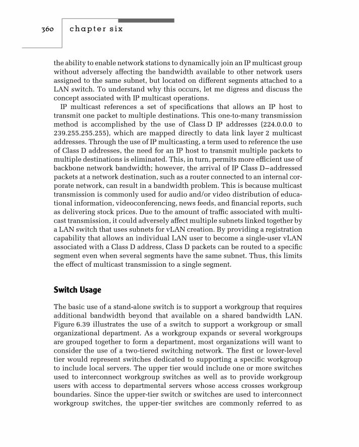
360 c h a p t e r s i x
the ability to enable network stations to dynamically join an IP multicast groupwithout adversely affecting the bandwidth available to other network usersassigned to the same subnet, but located on different segments attached to aLAN switch. To understand why this occurs, let me digress and discuss theconcept associated with IP multicast operations.
IP multicast references a set of specifications that allows an IP host totransmit one packet to multiple destinations. This one-to-many transmissionmethod is accomplished by the use of Class D IP addresses (224.0.0.0 to239.255.255.255), which are mapped directly to data link layer 2 multicastaddresses. Through the use of IP multicasting, a term used to reference the useof Class D addresses, the need for an IP host to transmit multiple packets tomultiple destinations is eliminated. This, in turn, permits more efficient use ofbackbone network bandwidth; however, the arrival of IP Class D–addressedpackets at a network destination, such as a router connected to an internal cor-porate network, can result in a bandwidth problem. This is because multicasttransmission is commonly used for audio and/or video distribution of educa-tional information, videoconferencing, news feeds, and financial reports, suchas delivering stock prices. Due to the amount of traffic associated with multi-cast transmission, it could adversely affect multiple subnets linked together bya LAN switch that uses subnets for vLAN creation. By providing a registrationcapability that allows an individual LAN user to become a single-user vLANassociated with a Class D address, Class D packets can be routed to a specificsegment even when several segments have the same subnet. Thus, this limitsthe effect of multicast transmission to a single segment.
Switch Usage
The basic use of a stand-alone switch is to support a workgroup that requiresadditional bandwidth beyond that available on a shared bandwidth LAN.Figure 6.39 illustrates the use of a switch to support a workgroup or smallorganizational department. As a workgroup expands or several workgroupsare grouped together to form a department, most organizations will want toconsider the use of a two-tiered switching network. The first or lower-leveltier would represent switches dedicated to supporting a specific workgroupto include local servers. The upper tier would include one or more switchesused to interconnect workgroup switches as well as to provide workgroupusers with access to departmental servers whose access crosses workgroupboundaries. Since the upper-tier switch or switches are used to interconnectworkgroup switches, the upper-tier switches are commonly referred to as

bridging and switching methods and performance issues 361
S S
10/100 MbpsEthernet switch
Legend:
S
= Segment
= Server
= Workstation
= 100-Mbps connection
Figure 6.39 Support for a small department or workgroup.
backbone switches. Figure 6.40 illustrates a possible use of one backboneswitch to interconnect two workgroup switches.
Since the backbone switch provides an interconnection between workgroupswitches as well as access to departmental servers, the failure of a backboneswitch would have a much more significant effect upon communications thanthe failure of a workgroup switch. Thus, you should consider using a backboneswitch with redundant power supplies, common logic, and other key modules.Then, the failure of one module at worst would only make one or a few portconnections inoperative. If you acquire one or a few additional port modulesyou would then have the ability to recable around a port failure withouthaving to wait for a replacement module to be shipped to your location.
When using one or more backbone switches, it is important to note thatthese switches directly affect the throughput between workgroups as wellas the transfer of information to and from departmental servers. Due tothis, most organizations will use dedicated 100-Mbps or Gigabit Ethernet

362 c h a p t e r s i x
DS DS
100 Mpsethernet switchor gigabit switch
10/100 Mbpsethernet switch
10/100 Mbpsethernet switch
WSWS
Legend:
DS =
WS = Workgroup server
= Segment
= Workstation
= 100-Mbps connection
Departmental server
Figure 6.40 Creating a two-tiered switch-based network.
switches for backbone operations. If this type of switch is not available at aneconomical cost, an alternative is to use a 10-/100-Mbps switch with enough100-Mbps ports to provide connections from workgroup switches as well asto departmental servers.
Organizational Switching
Building upon the departmental switching previously illustrated inFigure 6.40, you can use routers to interconnect geographically disperseddepartments. Doing so can result in an organizational Ethernet switchingnetwork that could span different locations in the same city, different cities,one or more states, a country, or the entire globe. Figure 6.41 illustrates theattachment of one router to a backbone switch, connecting the backboneat one location to a wide area network. Although the actual use of one

bridging and switching methods and performance issues 363
Wideareanetwork
RouterDSDS
WS WS
100/1000 Mbpsethernet switch
10/100 Mbpsethernet switch
10/100 Mbpsethernet switch
Legend:
DS = Departmental server
WS = Workgroup server
= Segment
= Workstation
= 100-Mbps connection
Figure 6.41 Interconnecting geographically dispersed switch-based net-works.
or more routers will be governed by our specific networking requirements,Figure 6.41 illustrates how you can connect one switch-based network toother switch-based networks.
As you design your network infrastructure you should consider the use ofone or more Ethernet switch features previously discussed in this chapter toenhance the performance of your network. For example, you may wish to usefull-duplex ports for local and departmental server connections. In addition,

364 c h a p t e r s i x
by the time you read this book economical 10-Gigabit switches should beavailable whose use could provide you with another option to consider whenconstructing a tiered network structure.
Layer 3 and Layer 4 Switching
In concluding this chapter we will briefly turn our attention to LAN switchingat layer 3 and layer 4 in the OSI Reference Model. In a TCP/IP environmentthis requires the LAN switch to look further into each frame to locate the IPheader and the TCP or UDP header and then a particular field in each header.This results in more processing being required to locate the applicable headerand field within the header that is used as a switching decision criterion.
The key advantage associated with the use of layer 3 and layer 4 LANswitches is the fact that they enable an organization to use the switch to tailortheir network to a specific operational requirement. For example, assume yourorganization operates several Web servers. Through the use of a layer 3 LANswitch you could direct traffic to different servers based upon the destinationIP address. Using a layer 4 LAN switch you could route traffic based upon IPaddress, TCP port, or both metrics. Doing so could provide your organizationwith the ability to perform a load balance operation.

c h a p t e r s e v e n
RoutersIn Chapter 5, we examined the basic operation and use of a variety of localarea networking components, including routers. Information presented inthat chapter will serve as a foundation for the more detailed discussion of theoperation and use of routers presented in this chapter.
7.1 Router Operation
By operating at the ISO Reference Model network layer, a router becomescapable of making intelligent decisions concerning the flow of informationin a network. To accomplish this, routers perform a variety of functions thatare significantly different from those performed by bridges. Unlike bridges,routers are addressable. Routers examine frames that are directly addressed tothem by looking at the network address within each frame to make their for-warding decisions. In an IP environment you would configure the IP addressof the router serving your network in a TCP/IP properties dialog box if you areusing Microsoft Windows. However, because routers were originally referredto as gateways and the latter term is still used as a reference to a router, youwould enter the IP address of the ‘‘gateway’’ serving your network. Thus, ifyour workstation needs to transmit a packet to an IP address on a differentnetwork, it will use the preconfigured gateway address to literally route thepacket to the router, which will then send it off the network towards itsultimate destination.
IP Support Overview
The most popular network layer protocol supported by routers is the InternetProtocol (IP), whose packet format was described in Chapter 5. Each IPnetwork has a distinct network address, and each interface on the networkhas a unique host address that represents the host portion of a 32-bit address.
365
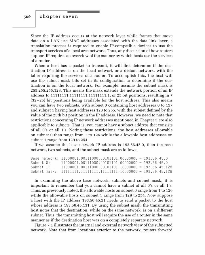
366 c h a p t e r s e v e n
Since the IP address occurs at the network layer while frames that movedata on a LAN use MAC addresses associated with the data link layer, atranslation process is required to enable IP-compatible devices to use thetransport services of a local area network. Thus, any discussion of how routerssupport IP requires an overview of the manner by which hosts use the servicesof a router.
When a host has a packet to transmit, it will first determine if the des-tination IP address is on the local network or a distant network, with thelatter requiring the services of a router. To accomplish this, the host willuse the subnet mask bits set in its configuration to determine if the des-tination is on the local network. For example, assume the subnet mask is255.255.255.128. This means the mask extends the network portion of an IPaddress to 11111111.11111111.11111111.1, or 25 bit positions, resulting in 7(32–25) bit positions being available for the host address. This also meansyou can have two subnets, with subnet 0 containing host addresses 0 to 127and subnet 1 having host addresses 128 to 255, with the subnet defined by thevalue of the 25th bit position in the IP address. However, we need to note thatrestrictions concerning IP network addresses mentioned in Chapter 5 are alsoapplicable to subnets. That is, you cannot have a subnet address that consistsof all 0’s or all 1’s. Noting these restrictions, the host addresses allowableon subnet 0 then range from 1 to 126 while the allowable host addresses onsubnet 1 range from 129 to 254.
If we assume the base network IP address is 193.56.45.0, then the basenetwork, two subnets, and the subnet mask are as follows:
Base network: 11000001.00111000.00101101.00000000 = 193.56.45.0Subnet 0: 11000001.00111000.00101101.00000000 = 193.56.45.0Subnet 1: 11000001.00111000.00101101.10000000 = 193.56.45.128Subnet mask: 11111111.11111111.11111111.10000000 = 193.56.45.128
In examining the above base network, subnets and subnet mask, it isimportant to remember that you cannot have a subnet of all 0’s or all 1’s.Thus, as previously noted, the allowable hosts on subnet 0 range from 1 to 126while the allowable hosts on subnet 1 range from 129 to 254. Now supposea host with the IP address 193.56.45.21 needs to send a packet to the hostwhose address is 193.56.45.131. By using the subnet mask, the transmittinghost notes that the destination, while on the same network, is on a differentsubnet. Thus, the transmitting host will require the use of a router in the samemanner as if the destination host was on a completely separate network.
Figure 7.1 illustrates the internal and external network view of the subnettednetwork. Note that from locations exterior to the network, routers forward

routers 367
Exterior view
193.56.45.0Router
193.56.45.128
193.56.45.0
Internal networkview
Figure 7.1 Using subnet masks to subdivide a common IP network address.
packets to the router connecting the two subnets as if no subnetting existed.The corporate router is configured via the use of subnet masks to differentiatehosts on one subnet from those on the other subnet. From an interior view,packets originating on one subnet must use the resources of the router to reachhosts on the other subnet as well as hosts on other networks.
Once the transmitting host notes that the destination IP address is either ona different network or different subnet, it must use the services of a router.Although each host will be configured with the IP address of the router, thehost will transport packets via the data link layer, which requires knowledgeof the 48-bit MAC address of the router port connected to the segment thetransmitting host resides on.
The translation between IP and MAC addresses is accomplished by the useof the Address Resolution Protocol (ARP). To obtain the MAC address of therouter’s LAN interface the host will broadcast an ARP request. This requestwill be received by all stations on the segment, with the router recognizing itsIP address and responding by transmitting an ARP response.
Because a continuous use of ARP would rapidly consume network band-width, hosts normally maintain the results of ARP requests in cache memory.Thus, once the relationship between an IP address and MAC address is learned,subsequent requests to transmit additional packets to the same destinationcan be accomplished by the host checking its cache memory.
When packets arrive at the router destined for a host on one of the subnets,a similar process occurs. That is, the router must obtain the MAC addressesassociated with the IP address to enable the packet to be transported by datalink layer frames to its appropriate destination. Thus, in addition to beingable to correctly support the transmission of packets from one interface to

368 c h a p t e r s e v e n
another, an IP-compatible router must also support the ARP protocol. Laterin this chapter we will discuss and describe additional protocols routerscan support.
Basic Operation and Use of Routing Tables
To see the basic operation of routers, consider the simple mesh structureformed by the use of three routers labeled R1, R2, and R3 in Figure 7.2a. Inthis illustration, three Ethernet networks are interconnected through the useof three routers.
The initial construction of three routing tables is shown in Figure 7.2b.Unlike bridges, which learn MAC addresses, routers are initially configured,and either routing tables are established at the time of equipment installationor the configuration process informs the router of addresses associated witheach of its interfaces and the attachment of networks and subnets, enablingthe device to construct its routing table. Thereafter, periodic communicationbetween routers updates routing tables to take into consideration any changesin internet topology and traffic.
In examining Figure 7.2b, note that the routing table for router R1 indi-cates which routers it must communicate with to access each interconnectedEthernet network. Router R1 would communicate with router R2 to reachnetwork 2, and with router R3 to reach network 3.
Figure 7.2c illustrates the composition of a packet originated by station S2on Ethernet 1 that is to be transmitted to station S12 on Ethernet 2. Router R1first examines the destination network address and notes that it is on anothernetwork. The router searches its routing table and finds that the frame shouldbe transmitted to router R2 to reach Ethernet network 2. Router R1 forwards theframe to router R2. Router R2 then places the frame onto Ethernet network 2for delivery to station S12 on that network.
Since routers use the network addresses instead of MAC addresses formaking their forwarding decisions, it is possible to have duplicate locallyadministered MAC addresses on each network interconnected by a router.The use of bridges, on the other hand, requires you to review and theneliminate any duplicate locally administered addresses. This process can betime-consuming when large networks are connected.
Another difference between bridges and routers is that a router can supportthe transmission of data on multiple paths between local area networks.Although a multiport bridge with a filtering capability can perform intelligentrouting decisions, the result of a bridge operation is normally valid for onlyone point-to-point link within a wide area network. In comparison, a router

routers 369
R1
R3
R2
S9
S10
S12
S3S2
S1
S7S6
S11
S4
S5 S8
Network 1Network 2
Network 3
R3
R2*1
2
3
R1
R2*
R1 R11
2
3
R2
*
R2
1
2
3
R3
(a) Simple mesh structure
(b) Routing tables
(c) Packet composition
Legend: = Router = Network stationSR
2.S12 1.S2 DATA
Destination Source
Figure 7.2 Basic router operation.
may be able to acquire information about the status of a large number of pathsand select an end-to-end path consisting of a series of point-to-point links. Inaddition, most routers can fragment and reassemble data. This permits packetsto flow over different paths and to be reassembled at their final destination.With this capability, a router can route each packet to its destination over the
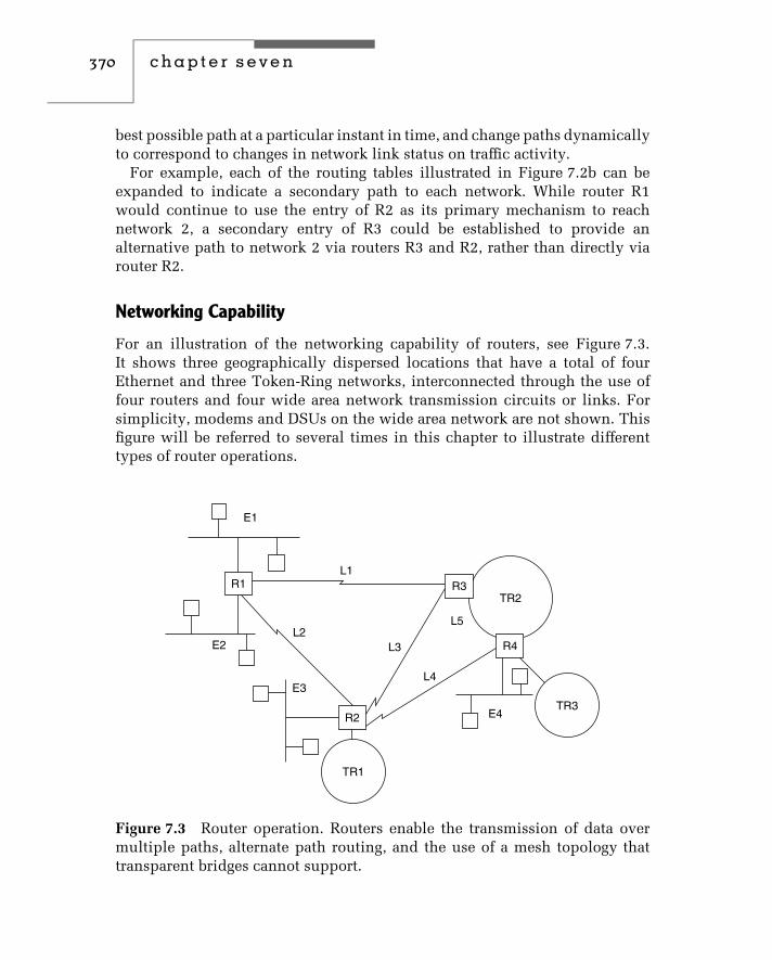
370 c h a p t e r s e v e n
best possible path at a particular instant in time, and change paths dynamicallyto correspond to changes in network link status on traffic activity.
For example, each of the routing tables illustrated in Figure 7.2b can beexpanded to indicate a secondary path to each network. While router R1would continue to use the entry of R2 as its primary mechanism to reachnetwork 2, a secondary entry of R3 could be established to provide analternative path to network 2 via routers R3 and R2, rather than directly viarouter R2.
Networking Capability
For an illustration of the networking capability of routers, see Figure 7.3.It shows three geographically dispersed locations that have a total of fourEthernet and three Token-Ring networks, interconnected through the use offour routers and four wide area network transmission circuits or links. Forsimplicity, modems and DSUs on the wide area network are not shown. Thisfigure will be referred to several times in this chapter to illustrate differenttypes of router operations.
R1
R2
R4
R3
E1
E2
E3
E4
TR1
TR3
TR2
L1
L2L3
L4
L5
Figure 7.3 Router operation. Routers enable the transmission of data overmultiple paths, alternate path routing, and the use of a mesh topology thattransparent bridges cannot support.

routers 371
In addition to supporting a mesh structure that is not obtainable fromthe use of transparent bridges, routers offer other advantages in the form ofaddressing, message processing, link utilization, and priority of service. Arouter is known to stations that use its service. Packets can thus be addresseddirectly to a router. This eliminates the necessity for the device to examine indetail every packet flowing on a network, and results in the router having toprocess only messages that are addressed to it by other devices.
Assume that a station on E1 transmits to a station on TR3. Depending onthe status and traffic on network links, packets could be routed via L1 anduse TR2 to provide a transport mechanism to R4, from which the packets aredelivered to TR3. Alternatively, links L2 and L4 could be used to providea path from R1 to R4. Although link availability and link traffic usuallydetermine routing, routers can support prioritized traffic, and may store low-priority traffic for a small period of time to allow higher-priority traffic to gainaccess to the wide area transmission facility. Because of these features, whichare essentially unavailable with bridges, the router is a more complex andmore expensive device.
7.2 Communication, Transport, and Routing Protocols
For routers to be able to operate in a network, they must normally be ableto speak the same language at both the data link and network layers. Thekey to accomplishing this is the ability to support common communication,transport, and routing protocols.
Communication Protocol
Communication protocols support the transfer of data from a station on onenetwork to a station on another network; they occur at the OSI networklayer. In examining Figure 7.4, which illustrates several common protocolimplementations with respect to the OSI Reference Model, you will note thatNovell’s NetWare uses IPX as its network communications protocol, whileIBM LANs use the PC LAN Support Program, and Microsoft’s LAN Manageruses the Internet Protocol (IP). Also note that when a TCP/IP stack is used,certain applications are transported by TCP while others are transported usingUDP; however, both TCP and UDP obtain their routing via the use of IP. Thismeans that a router linking networks based on Novell, IBM, and MicrosoftLAN operating systems must support those three communication protocols.Thus, router communication protocol support is a very important criterion

372 c h a p t e r s e v e n
OSI layer
Application
Presentation
Session
Transport
Network
Data link
Physical
Common protocol implementation
Application programsApplication protocols
NetBIOS
NetBIOS
Logical link control 802.2
Media access control
Transmission media:twisted pair, coax, fiber optic
TCP/IPapplications
TCP UDPPC LANsupportprogram
MicrosoftLAN manager
NetBIOSadvanced peer-to-
peer communications
NovellNetwork File
Server Protocol(NFSP)
IBMServer Mess-
age Block(SMB)
Xerox NetworkingSystem(XNS)
SequencedPacket Exchange
(SPX)
InternetworkPacket Exchange
(IPX)
InternetProtocol
(IP)
InternetProtocol
(IP)
TransmissionControl Protocol (TCP)
Transport ProtocolClass 4 (TCP4)
Figure 7.4 Common protocol implementations. Although Novell, IBM, andMicrosoft LAN operating system software support standardized physical anddata link operations, they differ considerably in their use of communicationand routing protocols.
in determining whether a particular product is capable of supporting yournetworking requirements.
Routing ProtocolThe routing protocol is the method used by routers to exchange routinginformation; it forms the basis for providing a connection across an internet.In evaluating routers, it is important to determine the efficiency of the routingprotocol, its effect upon the transmission of information, the method usedand memory required to construct routing tables, and the time required toadjust those tables. Examples of router-to-router protocols include XeroxNetwork Systems’ (XNS) Routing Information Protocol (RIP), TCP/IP’s RIP,Open Shortest Path First (OSPF), and Hello routing protocols.
Handling Nonroutable ProtocolsAlthough many mainframe users consider IBM’s System Network Architecture(SNA) as a router protocol, in actuality it is nonroutable in the traditional

routers 373
sense of having network addresses. This means that for a router to supportSNA or another nonroutable protocol, such as NetBIOS, the router cannotcompare a destination network address against the current network addressas there are no network addresses to work with. Instead, the router must becapable of performing one or more special operations to handle nonroutableprotocols. For example, some routers may be configurable such that SNAaddresses in terms of physical units (PUs) and logical units (LUs) can beassociated with pseudonetwork numbers, enabling the router to route anunroutable protocol. Another common method employed by some routers isto incorporate a nonroutable protocol within a routable protocol, a techniquereferred to as tunneling. A third method, and one considered by many to bethe old reliable mechanism, is to use bridging. Later in this chapter whenwe cover protocol-independent routers, we will describe methods that can beused to route nonroutable protocols, to include SNA traffic.
Transport Protocol
The transport protocol guarantees the delivery of information between twopoints. Here, the transport protocol represents the fourth layer illustrated inFigure 7.4. Examples of transport protocols include SPX, TCP, UDP, X.25, andFrame Relay.
There is a wide variety of communication and transport protocols in usetoday. Some of these protocols, such as Apple Computer’s AppleTalk, weredesigned specifically to operate on local area networks. Other protocols, suchas X.25 and Frame Relay, were developed as wide area network protocols.
Fifteen popular communication and transport protocols are listed below.Many routers support only a subset of these protocols.
♦ AppleTalk♦ Apple Domain♦ Banyan VINES♦ CHAOSnet♦ DECnet Phase IV♦ DECnet Phase V♦ DDN X.25♦ Frame Relay♦ ISO CLNS♦ HDLC♦ Novell IPX♦ SDLC

374 c h a p t e r s e v e n
♦ TCP/IP♦ Xerox XNS♦ X.25
7.3 Router Classifications
Depending upon their support of communication and transport protocols,routers can be classified into two groups: protocol-dependent and protocol-independent.
Protocol-Dependent Routers
To understand the characteristics of a protocol-dependent router, consider thenetwork illustrated in Figure 7.3. If a station on network E1 wishes to transmitdata to a second station on network E3, router R1 must know that the secondstation resides on network E3, and it must know the best path to use to reachthat network. The method used to determine the destination station’s networkalso determines the protocol dependency of the router.
If the station on network E1 tells router R1 the destination location, it mustsupply a network address in every LAN packet it transmits. This means thatall routers in the intranet must support the protocol used on network E1.Otherwise, stations on network E1 could not communicate with stationsresiding on other networks, and vice versa.
NetWare IPX Example
To illustrate the operation of a protocol-dependent router, let us assumethat networks E1 and E3 use Novell’s NetWare as their LAN operating sys-tem. The routing protocol used at the network layer between a station andserver on a Novell network is known as IPX. This protocol can also be usedbetween servers.
Under NetWare’s IPX, a packet addressed to a router will contain the desti-nation address in the form of network and host addresses, and the originationaddress in the form of the source network and source host addresses. Here,the IPX term host is actually the physical address of a network adapter card.
Figure 7.5a illustrates in simplified format the IPX packet compositionfor workstation A on network E1, transmitting data to workstation B onnetwork E3, under Novell’s NetWare IPX protocol.
After router R1 receives and examines the packet, it notes that the destinationaddress E3 requires the routing of the packet to router R2. It converts the first

routers 375
B E3 A E1 R1 Data
B E3 A E1 R2 Data
B E3 R2 A E1 R1 Data
(a) Packet from workstation A, network E1 to router R1
(b) Router (R1) to router (R2) packet
(c) Router R2 converts packet for placement on network E3
Figure 7.5 NetWare IPX routing.
packet into a router (R1) to router (R2) packet, as illustrated in Figure 7.5b. Atrouter R2, the packet is again examined. Router R2 notes that the destinationnetwork address (E3) is connected to that router, so it reconverts the packetfor delivery onto network E3. It does this by converting the destinationrouter address to a source router address and transmitting the packet ontonetwork E3. This is illustrated in Figure 7.5c.
Addressing Differences
In the preceding example, note that each router uses the destination worksta-tion and network addresses to transfer packets. If all protocols used the sameformat and addressing structure, routers would be protocol-insensitive at thenetwork layer. Unfortunately, this is not true. For example, TCP/IP addressingconventions are very different from those used by NetWare. This means thatnetworks using different operating systems require the use of multiprotocolrouters configured to perform address translation. Each multiprotocol routermust maintain separate routing tables for each supported protocol, requiringadditional memory and processing time.
Other Problems
Two additional problems associated with protocol-dependent routers arethe time required for packet examination and the fact that not all LANprotocols are routable. If a packet must traverse a large network, the timerequired by a series of routers to modify the packet and assure its deliv-ery to the next router can significantly degrade router performance. Toovercome this problem, organizations should consider the use of a framerelay service.

376 c h a p t e r s e v e n
In addition to providing an enhanced data delivery service by eliminatingerror detection and correction within the network, the use of a frame relayservice can significantly reduce the cost of routers. Consider, for example,the network in Figure 7.3, in which four routers are interconnected throughthe use of five links. To support transmission on five links, the routersrequire ten ports. Normally, each router port is obtained as an adapter cardinstalled in a high-performance computer. If a frame relay service is used,the packet network providing that service also provides the routing paths tointerconnect routers, as illustrated in Figure 7.6. This reduces the numberof required router ports to four. This reduction can result in a considerablehardware savings.
In addition to using a frame relay service provider, another method that canreduce the cost of router hardware and communications circuits is obtainedfrom establishing a virtual private network (VPN) through the Internet. Indoing so, you would need to consider encryption of data as the Internet rep-resents an open, public network. However, the physical topology associatedwith connecting geographically separated locations would remain similar tothat shown in Figure 7.6, with the frame relay packet network service beingreplaced by the Internet.
A second problem associated with protocol-dependent routers is the factthat some LAN protocols cannot be routed using that type of device. This isbecause some LAN protocols, such as NetBIOS and IBM’s LAN Server — andunlike NetWare, DECnet, and TCP/IP — do not include routing information
R1R3
R4R2
Frame relaypacket network
service
Figure 7.6 Using a frame relay service. If a frame relay service is used,the packet network provides the capability for interconnecting each networkaccess port to other network access ports. Thus, only one router port is requiredto obtain an interconnection capability to numerous routers connected tothe network.

routers 377
within a packet. Instead, those protocols employ a user-friendly device-naming convention instead of using network and device addresses. Thisconvention permits such names as ‘‘Gil’s PC’’ and ‘‘Accounting Printer’’ tobe used. For example, IBM’s NetBIOS was designed to facilitate program-to-program communication by hiding the complexities of network addressingfrom the user. Thus, NetBIOS uses names up to 16 alphanumeric characterslong to define clients and servers on a network. Unfortunately, NetBIOS doesnot include a facility to distinguish one network from another, since it lacksa network addressing capability. Such protocols are restricted to using thephysical addresses of adapter cards, such as Ethernet source and destinationaddresses. Since a protocol-dependent router must know the network onwhich a destination address is located, it cannot in a conventional senseroute such protocols. A logical question, then, is how a router interconnectsnetworks using an IBM LAN protocol or a similar nonroutable protocol.The answer to this question will depend upon the method used by the routermanufacturer to support nonroutable protocols. As previously discussed, suchmethods can include bridging, tunneling, or the configuration of a router thatenables pseudonetwork addresses to be assigned to each device.
Protocol-Independent Routers
A protocol-independent router functions as a sophisticated transparent bridge.That is, it addresses the problem of network protocols that do not havenetwork addresses. It does this by examining the source addresses on con-nected networks to learn automatically what devices are on each network.The protocol-independent router assigns network identifiers to each networkwhose operating system does not include network addresses in its networkprotocol. This activity enables both routable and nonroutable protocols to beserviced by a protocol-dependent router.
In addition to building address tables automatically like a transparentbridge, a protocol-independent router exchanges information concerning itsrouting directions with other internet routers. This enables each router tobuild a map of the interconnected networks. The method used to build thenetwork map falls under the category of a link state routing protocol, whichis described later in this chapter.
Advantages
There are two key advantages to using protocol-independent routers. Thoseadvantages are the abilities of routers to learn network topology automaticallyand to service nonroutable protocols. The ability to learn network topology

378 c h a p t e r s e v e n
automatically can considerably simplify the administration of an internet. Forexample, in a TCP/IP network, each workstation has an IP address and mustknow the IP addresses of other LAN devices it wants to communicate with.
IP addresses are commonly assigned by a network administrator, and theymust be changed if a station is moved to a different network, or if a network issegmented because of a high level of traffic or other reason. In such situations,LAN users must be notified about the new IP address, or they will notbe able to locate the moved station. Obviously, the movement of stationswithin a building between different LANs could become a considerableadministrative burden. The ability of a protocol-independent router to learnaddresses automatically removes the administrative burden of notifying usersof changes in network addresses.
An exception to the preceding occurs through the use of the DynamicHost Configuration Protocol (DHCP). Through the use of a DHCP server andappropriate client software, stations are dynamically assigned IP addressesfor a relatively short period of time. Once they complete an application theserver can reassign the address to a new station. Although the use of theDHCP can ease the administrative burden of configuring and reconfiguring IPworkstations, it requires the use of a server and client software. Thus, therecontinues to be no free lunch in networking.
The ability to route nonroutable protocols can be of considerable assistancein integrating IBM SNAs into an enterprise network. Otherwise, without theuse of protocol-independent routers, organizations may have to maintainseparate transmission facilities for SNA and LAN traffic.
Supporting SNA Traffic
Figure 7.7 illustrates an example of the use of protocol-independent routersto support both inter-LAN and SNA traffic. In this example, an IBM SNAnetwork, a 3174 control unit with a Token-Ring adapter (TRA) at a remotesite provides communications connectivity to an IBM 3745 communicationscontroller at a central site. Routers must be capable of routing both SNA andLAN traffic to enable the use of a common transmission facility between thecentral and remote site.
Methods to Consider
There are essentially three methods by which SNA and LAN traffic canbe combined for routing over a common network: encapsulation, conver-sion, and protocol-independent routing. Under the encapsulation method,SNA packets are modified so that another protocol’s header, addressing,

routers 379
Remote site
TR1
TR2
TRA
3174
R1 R2
E1 E2
Central site
IBM3745
Host
Figure 7.7 Supporting SNA traffic. A protocol-independent router can sup-port SNA traffic and other LAN traffic over a common transmission facility.
and trailer fields surround each SNA packet. For example, a TCP/IP pro-tocol–dependent router would encapsulate SNA into TCP/IP packets forrouting through a TCP/IP network. Since a TCP/IP packet has over 60 bytesof overhead, and the average SNA packet is 30 bytes in length, encapsula-tion can reduce performance considerably when transmission occurs overlow-speed WAN links. A second disadvantage of encapsulation is thatit requires the existence of a corporate network using the encapsulationprotocol. Otherwise, you would have to build this network to obtain anencapsulation capability.
The second method used for integrating SNA traffic with LAN traffic occursthrough the use of protocol conversion. This technique eliminates the needfor adding network headers and enhances the efficiency of the protocolintegration efforts.
The third method by which an SNA network can be integrated with LANtraffic is through protocol-independent routing. Protocol-independent routersassign a LAN device address to each SNA control unit and communicationscontroller. Then, SNA packets are prefixed with source and destinationaddresses to permit their routing through the internet. At the destinationrouter, the addressing information is removed, and the SNA packets aredelivered to their destination in their original form. Since the addition ofsource and destination addresses adds a significantly lower number of bytesthan an encapsulation process, overhead is reduced. This, in turn, enablesyou to consider using lower-speed circuits to interconnect locations.

380 c h a p t e r s e v e n
Another advantage of protocol-independent routing over encapsulationrelates directly to the operation of SNA networks, with several SNA operationalcharacteristics warranting attention. They will help us appreciate the advan-tages of protocol-independent routing, and they will explain the rationale forsuch routers’ requiring a traffic priority mechanism to support SNA trafficefficiently.
Need for Priority Mechanism
In its original incarnation, SNA represents a hierarchically structured network,as shown in Figure 7.8. Here, the communications controller communicateswith control units, which in turn communicate with attached terminal devices.The communications controller periodically polls each control unit, and thecontrol unit periodically polls each terminal device. If there is no datato transmit in response to a poll, each polled device indicates this factto the higher-level device by responding negatively to the poll. Thus, thecommunications controller expects to receive a response to each poll itgenerates. In fact, if it does not receive a response within a predefinedperiod of time (typically less than five seconds), the communications con-troller will assume that the control unit has malfunctioned, terminate any
Controlunit
Controlunit
Controlunit
Communicationscontroller
Host computer
Figure 7.8 SNA network hierarchy. In an SNA network, communicationscontrollers poll control units, which in turn poll attached devices.

routers 381
active sessions to devices attached to the control unit, and then attemptto reestablish communications by sending an initialization message to thecontrol unit.
When SNA and LAN traffic is integrated into a common router-basednetwork, the operation of routers can adversely affect SNA traffic becauseof the time delays associated with routing and encapsulation. For example,routers may alter the path used to transmit data, depending on internet trafficand circuit availability. If path switching makes the SNA traffic exceed itstimeout threshold, the communications controller will terminate sessions andreinitialize control units that fail to respond to its poll within the predefinedtime period. Similarly, delays caused by encapsulation can also result inunintended timeouts.
To prevent unintended timeouts caused by path switching, some vendorshave added a traffic priority mechanism to their protocol-independent routingcapability. This priority mechanism enables users to assign a higher priority toSNA traffic than to LAN traffic, thus enabling SNA data to be forwarded acrosswide area networks ahead of other inter-LAN traffic. This can considerablyreduce or even eliminate the potential for LAN traffic to obstruct the flow ofSNA data; it may also result in unintended timeouts, inadvertently causingsession terminations.
7.4 Routing Protocols
The routing protocol is the key element to transferring information acrossan internet in an orderly manner. The protocol is responsible for developingpaths between routers, using a predefined mechanism.
Types of Routing Protocols
There are two types of routing protocols: interior and exterior domain. Here,we use the term domain to refer to the connection of a group of networks toform a common entity, such as a corporate or university enterprise network.
Interior Domain Routing Protocols
An interior domain routing protocol is used to control the flow of informationwithin a series of separate networks that are interconnected to form an internet.Thus, interior domain routing protocols provide a mechanism for the flowof information within a domain and are also known as intradomain routing

382 c h a p t e r s e v e n
protocols. Such protocols create routing tables for each autonomous systemwithin the domain, using such metrics as the hop count or time delay todevelop routes from one network to another within the domain. Examples ofinterior domain routing protocols include RIP, OSPF, and Hello.
Exterior Domain Routing Protocols
Exterior domain routing protocols are used to connect separate domainstogether. Thus, they are also referred to as interdomain routing protocols.Examples of interdomain routing protocols include the Exterior GatewayProtocol (EGP), the Border Gateway Protocol (BGP), and the Inter-DomainRouting Protocol (IDRP). Unlike interior domain routing protocols, whichare focused on the construction of routing tables for data flow withina domain, interdomain routing protocols specify the method by whichrouters exchange information concerning what networks they can reach oneach domain.
Figure 7.9 illustrates the use of interior and exterior domain routing proto-cols. In this example, OSPF is the intradomain protocol used in Domain A,while RIP is the intradomain protocol used in Domain B. Routers in DomainsA and B use the interdomain routing protocols EGP and/or BGP to determinewhat networks on other domains they can reach.
Exterior Gateway Protocol
There are four basic functions performed by the Exterior Gateway Protocol.First, the EGP performs an acquisition function, which enables a router in onedomain to request information exchange with a router on another domain.Since routers also serve as gateways to the domain, they are sometimesreferred to as gateways. A second function performed by the router gateway isto test periodically whether its EGP neighbors are responding. The third andmost important function performed by the EGP is to enable router gatewaysto exchange information concerning the networks in each domain by trans-mitting routing update messages. The fourth function involves terminating anestablished neighbor relationship between gateways on two domains.
To accomplish its basic functions, EGP defines nine message types.Figure 7.10 illustrates EGP message types associated with each of the threebasic features performed by the protocol.
Under the EGP, once a neighbor is acquired, Hello messages must betransmitted at a minimum of 30-second intervals. In addition, routing updatesmust be exchanged at a minimum of two-minute intervals. This exchange ofinformation at two-minute intervals can result in the use of a considerable

routers 383
R R
R
R
R
R
OSPF
EGP,BGPInterdomain
(exterior)routing protocols
Intradomain (interior)routing protocols
Domain B
RIP
Domain A
Figure 7.9 Interior and exterior routing protocols. An interior routing pro-tocol controls the flow of information within a collection of interconnectednetworks known as a domain. An exterior routing protocol provides routerswith the ability to determine what networks on other domains they can reach.
amount of the bandwidth linking domains when the number of networks oneach domain is large, or when the circuits linking domains consist of low-speed lines. The Border Gateway Protocol was developed to alleviate thosepotential problems.
Border Gateway Protocol
The Border Gateway Protocol represents a follow-on to the EGP. Unlikethe EGP, in which all network information is exchanged at two-minute orshorter intervals, the BGP transmits incremental updates as changes occur.This can significantly reduce the quantity of data exchanged between routergateways, thus freeing up a considerable amount of circuit bandwidth for thetransmission of data. Both the EGP and the BGP run over TCP/IP and arestandardized by Internet documents RFC904 and RFC1105, respectively.

384 c h a p t e r s e v e n
Function Message type
Acquiring neighbors
Neighbor reachability
Routing update
De-acquiring neighbors
Domain A
R R
R
R
R
R
Domain B
Acquisition request
Acquisition confirmor
Acquisition refuse
Hello
I heard you
Poll request
Routing update
Cease request
Cease confirm
Figure 7.10 Exterior gateway protocol message types.
Types of Interior Domain Routing Protocols
As previously discussed, interior domain routing protocols govern the flow ofinformation between networks. This is the type of routing protocol that is ofprimary interest to most organizations. Interior domain routing protocols can

routers 385
be further subdivided into two broad categories, based on the method they usefor building and updating the contents of their routing tables: vector distanceand link state.
Vector Distance Protocol
A vector distance protocol constructs a routing table in each router, andperiodically broadcasts the contents of the routing table across the internet.When the routing table is received at another router, that device examinesthe set of reported network destinations and the distance to each destination.The receiving router then determines whether it knows a shorter route to anetwork destination, finds a destination it does not have in its routing table,or finds a route to a destination through the sending router where the distanceto the destination changed. If any one of these situations occurs, the receivingrouter will change its routing tables.
The term vector distance relates to the information transmitted by routers.Each router message contains a list of pairs, known as vector and distance.The vector identifies a network destination, while the distance is the distancein hops from the router to that destination.
Figure 7.11 illustrates the initial distance vector routing table for the routersR1 and R2 shown in Figure 7.3. Each table contains an entry for each directlyconnected network and is broadcast periodically throughout the internet.The distance column indicates the distance in hops to each network fromthe router.
At the same time router R1 is constructing its initial distance vectortable, other routers are performing a similar operation. The lower portionof Figure 7.11 illustrates the composition of the initial distance vector tablefor router R2. As previously mentioned, under a distance vector protocol, thecontents of each router’s routing table are periodically broadcast. When routersR1 and R2 broadcast their initial distance vector routing tables, each routeruses the received routing table to update its initial routing table. Figure 7.12
Figure 7.11 Initial distance vector routing tables.

386 c h a p t e r s e v e n
Figure 7.12 Initial routing table update.
illustrates the result of this initial routing table update process for routers R1and R2.
As additional routing tables are exchanged, the routing table in each routerwill converge with respect to the internet topology. However, to ensurethat each router knows the state of all links, routing tables are periodicallybroadcast by each router. Although this process has a minimal effect uponsmall networks, its use with large networks can significantly reduce availablebandwidth for actual data transfer. This is because the transmission of lengthyrouter tables will require additional transmission time in which data cannotflow between routers.
Popular vector distance routing protocols include the TCP/IP Routing Infor-mation Protocol (RIP), the AppleTalk Routing Table Management Protocol(RTMP), and Cisco’s Interior Gateway Routing Protocol (IGRP).
Routing Information Protocol
Under RIP, participants are either active or passive. Active participants arenormally routers that transmit their routing tables, while passive machines lis-ten and update their routing tables based upon information supplied by otherdevices. Normally, host computers are passive participants, while routers areactive participants.
Operation
Under RIP, an active router broadcasts its routing table every 30 seconds.Each routing table entry contains a network address and the hop count tothe network. To illustrate an example of the operation of RIP, let’s redrawthe network previously shown in Figure 7.3 in terms of its links and nodes,

routers 387
A
C D
B1
3
4
25
Figure 7.13 Redrawing the network in Figure 7.3 interms of its links and nodes.
replacing the four routers by the letters A, B, C, and D for simplicity ofillustration. Figure 7.13 contains the revised network consisting of four nodesand five links.
When the routers are powered up they only have knowledge of theirlocal conditions. Thus, each routing table would contain a single entry. Forexample, the table of router n would have the following value:
From n to Link Hop Count
n local 0
For the router represented by node A, its table would then become:
From A to Link Hop Count
A local 0
Thirty seconds after being turned on, node A will broadcast its distancevector (A = 0) to all its neighbors, which, in Figure 7.13 are nodes B and C.Node B receives on link 1 the assistance vector A = 0. Upon receipt of thismessage, it updates its routing table as follows, adding one to the hop countassociated with the distance vector supplied by node 1:
From B to Link Hop Count
B Local 0A 1 1

388 c h a p t e r s e v e n
Node B can now prepare its own distance vector (B = 0, A = 1) and transmitthat information on its connections (links 1, 3, and 5).
During the preceding period node C would have received the initial distancevector transmission from node A. Thus, node C would have updated its routingtable as follows:
From C to Link Hop Count
C Local 0A 2 1
Once it updates its routing table, node C will then transmit its distancevector (C = 0, A = 1) on links 2, 3, and 4.
Assuming the distance vector from node B is now received at nodes Aand C, each will update their routing tables. Thus, their routing tables wouldappear as follows:
From A to Link Hop Count
A Local 0B 1 1
From C to Link Hop Count
C Local 0A 2 1B 3 1
At node D, its initial state is first modified when it receives the distancevector (B = 0, A = 1) from node B. Since D received that information onlink 5, it updates its routing table as follows, adding one to each receivedhop count:
From D to Link Hop Count
D Local 0B 5 1A 5 2
Now, let’s assume node D receives the update of node C’s recent update(C = 0, A = 1, B = 1) on link 4. As it does not have an entry for node C, itwill add it to its routing table by entering C = 1 for link 4. When it adds 1 to

routers 389
the hop count for A received on link 4, it notes that the value is equal to thecurrent hop count for A in its routing table. Thus, it discards the informationabout node A received from node C. The exception to this would be if therouter maintained alternate routing entries to use in the event of a link failure.Next, node D would operate upon the vector B = 1 received on link 4, addingone to the hop count to obtain B = 2. Since that is more hops than the currententry, it would discard the received distance vector. Thus, D’s routing tablewould appear as follows:
From D to Link Hop Count
D Local 0C 4 1B 5 1A 5 2
The preceding example provides a general indication of how RIP enablesnodes to learn the topology of a network. In addition, if a link should fail, thecondition can be easily compensated for as similar to bridge table entries, thoseof routers are also time stamped and the periodic transmission of distancevector information would result in a new route replacing the previouslycomputed one.
One key limitation of RIP is the maximum hop distance it supports. Thisdistance is 16 hops, which means that an alternative protocol must be usedfor large networks.
Configuration Example
Because Cisco Systems manufactures over 70 percent of all routers we willuse its Internetworking Operating System (IOS) to illustrate an example ofthe router configuration process. In doing so we will assume that during therouter setup process you entered the name of the router as Cisco, an enablepassword which governs access to the router’s privileged mode of operationas ‘‘wxyz,’’ and agreed to configure IP on a serial and Ethernet interface.Figure 7.14 illustrates the interfaces of the router and the assignment of IPaddresses to each router interface.
Router Modes
Cisco routers support two modes of operation — user and privileged. The usermode is the default mode when you reboot a router and access it via a direct

390 c h a p t e r s e v e n
205.131.175.1
198.78.46.1
s0
e0
Router
Network
Figure 7.14 Configuring a Cisco router to use RIP as its routing protocol.
console connection or access the router via Telnet. When you access a routerand are in its user mode this fact is denoted by the router name followedby the greater than (>) sign. If your router name is Cisco, the user modeprompt becomes:
Cisco >
Once in user mode you can display many items concerning the router toinclude its configuration; however, you cannot configure the router. To obtainthe ability to configure the router you need to be in its privileged mode. To doso, you need to type ‘‘enable’’ at the user mode prompt and then press Enter.You will then be prompted to enter the enable password, after which theprompt changes to the router name followed by the pound sign (#) — called ahash sign in the UK. The following example illustrates how you would move

routers 391
from the user mode into the privileged mode when using a Cisco router:
Cisco > enable
Cisco > Password : wxyz
Cisco#
Cisco’s IOS uses a command interpreter to execute commands you enter.That interpreter is referred to as the Exec and user and privileged modes canbe considered to represent different levels of the Exec. Assuming you are in theprivileged mode, you can obtain the ability to configure a router by enteringthe command ‘‘configure,’’ or if you want to eliminate a prompt, enter thecommand ‘‘config t’’ to denote you are configuring the router from a terminalas opposed to configuring it from memory or the network. To configure thes0 (serial 0) interface with the IP address 205.131.175.1, you would enter thefollowing IOS statements:
Cisco#config t
Enter configuration commands, one per line, End with CNTL/Z
Cisco(config)#interface s0
Cisco(config-if)#ip address 205.131.175.1 255.255.255.0
Once you define the IP addresses for each interface you need to configure arouting protocol, so let’s do so. Since RIP is limited to 16 hops (0 through15), which makes it suitable for small to medium networks, let’s assumeyou will use this routing protocol. To configure RIP you would type ‘‘configt’’ at the privileged prompt. At the configuration prompt you would enter‘‘router rip’’ to select RIP as the routing protocol. Next you would enter thekeyword ‘‘network’’ followed by what is referred to as the major networknumber at the next config prompt. Here Cisco uses the term major networknumber to reference the IP network address for a Class A, B or C networkdirectly connected to the router. From Figure 7.14 you would note that thereis only one network connected to the router. Thus, you would configure RIPas follows:
Cisco#config t
Enter configuration commands, one per line. End with CNTL/Z.
Cisco(config)#router rip
Cisco(config-router)#network 198.78.46.0

392 c h a p t e r s e v e n
If you had more than one network connected to the router you would repeatusing the keyword ‘‘network’’ followed by the IP address for each network con-nected to the router. Once you finish entering the directly connected networksyou would press CNTL + Z to end the configuration session. Now that wehave an appreciation of how we would configure RIP in a Cisco environment,let’s continue our examination of a few additional routing protocols.
Routing Table Maintenance Protocol
The Routing Table Maintenance Protocol (RTMP) was developed by AppleComputer for use with that vendor’s AppleTalk network. Under RTMP,each router transmits messages to establish routing tables and update themperiodically. The update process, during which information on an internetis exchanged between routers, also serves as a mechanism for implementingalternate routing. This is because the absence of update information for agreater than expected period of time converts the status of an entry in otherrouter routing tables from ‘‘good’’ to ‘‘suspect’’ and then to ‘‘bad.’’
RTMP is delivered by AppleTalk’s Data Delivery Protocol (DDP), whichis a network layer connectionless service operating between two upper-layer processes referred to as sockets. Four types of packets are specified byRTMP: data, request, route data request, and response. Routing updates aretransmitted as data packets. End nodes transmit request packets to acquireinformation about the identity of the internet routers (IRs) to which they cantransmit nonlocal packets. Internet routers respond to route request packetswith response packets, while end nodes that want to receive an RTMP datapacket indicate this by sending a route data request packet. The latter packettype is also used by nodes that require routing information from IRs notdirectly connected to their network.
Routing Process
In the AppleTalk routing process, the source node first examines the destina-tion network number. If the packet has a local network address, it is passedto the data link layer for delivery. Otherwise, the packet is passed to any ofthe IRs that reside on a network segment. The IR will examine the destinationaddress of the packet and then check its routing tables to determine the nexthop, routing the packet on a specific port that enables it to flow toward thenext hop. Thus, a packet will travel through the internet on a hop-by-hopbasis. When the packet reaches an IR connected to the destination network,the data link layer is used to deliver the packet to its local destination.
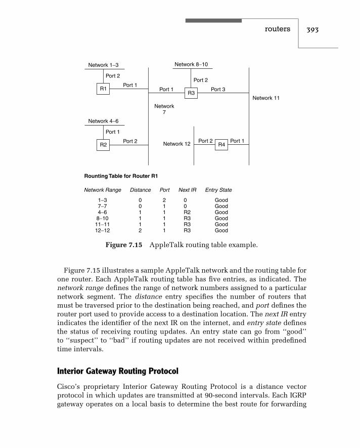
routers 393
Network 1−3
Network7
Network 12
Network 11
R1
Port 2
Port 1
Network 8−10
Port 2
Port 3
Port 2 Port 1
Port 1
Network 4−6
R2
Port 1
Port 2
R3
R4
Rounting Table for Router R1
Network Range
1−37−74−68−1011−1112−12
Distance
001112
Port
211111
Next IR
00R2R3R3R3
Entry State
GoodGoodGoodGoodGoodGood
Figure 7.15 AppleTalk routing table example.
Figure 7.15 illustrates a sample AppleTalk network and the routing table forone router. Each AppleTalk routing table has five entries, as indicated. Thenetwork range defines the range of network numbers assigned to a particularnetwork segment. The distance entry specifies the number of routers thatmust be traversed prior to the destination being reached, and port defines therouter port used to provide access to a destination location. The next IR entryindicates the identifier of the next IR on the internet, and entry state definesthe status of receiving routing updates. An entry state can go from ‘‘good’’to ‘‘suspect’’ to ‘‘bad’’ if routing updates are not received within predefinedtime intervals.
Interior Gateway Routing Protocol
Cisco’s proprietary Interior Gateway Routing Protocol is a distance vectorprotocol in which updates are transmitted at 90-second intervals. Each IGRPgateway operates on a local basis to determine the best route for forwarding

394 c h a p t e r s e v e n
data packets. Unlike protocols that require each router to have a completerouting table, each IGRP router computes only a portion of the routing table,based on its perspective of the Intranet. This enables the IGRP to supportdistributed routing without requiring each router to have a complete view ofthe internet.
Other features of the IGRP include the ability to establish routes automat-ically, perform load balancing dynamically over redundant links, and detectand remove bad circuits from the internet routing tables it develops. Routesare declared inaccessible if an update is not received within three updateperiods (270 seconds). After five update periods (450 seconds), the route isremoved from the routing table.
IGRP, unlike RIP, supports a wide range of metrics that can be used togovern routing. Both reliability and load can be considered as well as inter-network delay and the bandwidth on a link. The use of IGRP occurs withinan autonomous system (AS) that represents a group of routers connectingnetworks that use a common routing protocol. This makes it possible for anetwork administrator to set weighting factors for each routing metric or toallow the protocol to use default weights. An enhanced IGRP (EIGRP) wasintroduced by Cisco that incorporates the capabilities of link-state protocolsinto distant vector protocols. Under EIGRP a router stores all of its neighbors’routing tables so it can rapidly adapt to alternate routes. Other improvementsunder EIGRP include support for variable-length subnet masks and the trans-mission of partial table entries when the metric for a route changes in placeof full periodic updates. As you might expect, in a large AS, this considerablyreduces the overhead and the adverse effect of bandwidth congestion due totable updates.
Link State Protocols
A link state routing protocol addresses the traffic problem associated withany large networks that use a vector distance routing protocol. It does thisby transmitting routing information only when there is a change in oneof its links. A second difference between vector difference and link stateprotocols concerns the manner in which a route is selected when multipleroutes are available between destinations. For a vector distance protocol,the best path is the one that has the fewest intermediate routers on hopsbetween destinations. A link state protocol, however, can use multiple pathsto provide traffic balancing between locations. In addition, a link state protocolpermits routing to occur based on link delay, capacity, and reliability. This

routers 395
provides the network manager with the ability to specify a variety of routedevelopment situations.
SPF Algorithms
Link state routing protocols are implemented by a class of algorithms knownas Shortest Path First (SPF). Unfortunately, this is a misnomer, since routingis not based on the shortest path.
The use of SPF algorithms requires each participating router to have com-plete knowledge of the intranet topology. Each router participating in an SPFalgorithm then performs two tasks: status testing of neighboring routers andperiodic transmission of link status information to other routers.
To test neighboring routers, a short message is periodically transmitted.If the neighbor replies, the link is considered to be up. Otherwise, theabsence of a reply after a predefined period of time indicates that the linkis down.
To provide link status information, each router will periodically broadcasta message indicating the status of each of its links. Unlike the vector distanceprotocol, in which routes are specified, an SPF link status message simplyindicates whether communications are possible between pairs of routers.Using information in the link status message, routers are able to update theirnetwork maps.
Unlike vector distance protocols, in which tables are required to beexchanged, link state protocols such as SPF algorithms exchange a muchlower volume of information in the form of link status queries and replies.Then, SPF participating routers simply broadcast the status of each of theirlinks, and other routers use this information to update their intranet maps.This routing technique permits each router to compute routes independentlyof other routers, and eliminates the potential for the table flooding that canoccur when a vector state protocol is used to interconnect a large numberof networks.
To illustrate the operation of a link state routing protocol, let us return tothe internet configuration previously illustrated in Figure 7.15. Figure 7.16indicates the initial network map for router R1. This map lists the destinationof all networks on the intranet from router R1, with their distances androutes. Note that if multiple routes exist to a destination, each route is listed.This defines a complete network topology, and allows alternate routes to beselected if link status information indicates that one or more routes cannotbe used.

396 c h a p t e r s e v e n
Figure 7.16 Router R1 initial network map.
Figure 7.17 Link status messages.
Let us suppose that at a particular point in time, the link status messagesgenerated by the routers in the intranet are as indicated in Figure 7.17.Note that both routers R2 and R3 have determined that link L3 is down.Using this information, router R1 would then update the status columnfor its network map. Since link L3 is down, all routes that require a data

routers 397
flow between R2 and R3 would have their status changed to ‘‘down.’’ Forexample, for destination E3 via route R3, R2 would have its status changedto ‘‘down.’’ Since the minimum distance to E3 is 1 hop via router R2, thefailure of link L3 would not affect data flow from router R1 to networkE3. Now consider the effect of link L2 becoming inoperative. This wouldaffect route R2, which has the minimum distance to network E3. It wouldstill leave route R3 = R4 = R2, although this route would have a distanceof three hops. Of course, when a new link status message indicates that apreviously declared down link is up, each router’s network map is updatedaccordingly.
Examples of link state protocols include Open Shortest Path First (OSPF),OSI Intermediate System to Intermediate System (IS-IS), DECnet Phase V, andIBM’s Advanced Peer-to-Peer Networking (APPN). Due to space limitations,we will review briefly the operational features of only the first of these linkstate protocols.
Open Shortest Path First Protocol
The OSPF protocol is an interior domain routing protocol that uses theSPF algorithm. Like the EGP, the OSPF protocol consists of a small core ofdifferent types of messages. Under the OSPF protocol, five message typesare defined.
A Hello message is used to test the reachability of other devices. Adatabase description message passes the topology. The remaining messagetypes include a link status request, a link status update, and a link statusacknowledgement message.
Initially, OSPF generates database description messages to initialize itsnetwork topology database. These messages are flooded through the domain.However, once a topological database is formed, routing table updates aretransmitted at 30-minute intervals unless there is a change in the network, inwhich case there is an immediate update.
Like the EGP, OSPF routers use a Hello message to discover their neighbors.One of the key features of the OSPF protocol is its ability to authenti-cate messages. This means that you can’t entice routers to transmit pack-ets to a specific computer for examination or interception by generatinglow-cost routes. Another key feature of the OSPF protocol is its abil-ity to support multiple active paths of equal weight: it selects each pathin a round-robin manner. Table 7.1 provides a summary of 16 commonrouting protocol abbreviations, their meanings, and a short description ofeach protocol.

398 c h a p t e r s e v e n
TABLE 7.1 Common Routing Protocols
AURP AppleTalk Update Routing Protocol. This routing protocol is implementedin Apple networks and sends changes to routing tables via updates.
BGP Border Gateway Protocol. This is a TCP/IP interdomain routing protocol.
CLNP Connectionless Network Protocol. This is the OSI version of the IP routingprotocol.
DDP Datagram Delivery Protocol. This routing protocol is used in Apple’sAppleTalk network.
EGP Exterior Gateway Protocol. This TCP/IP protocol is used to locatenetworks on another domain.
IDRP Inter-Domain Routing Protocol. This is the OSI interdomain routingprotocol.
IGP Interior Gateway Protocol. This TCP/IP protocol is used by routers tomove information within a domain.
IGRP Interior Gateway Routing Protocol. This is a proprietary routing protocoldeveloped by Cisco Systems.
IP Internet Protocol. This is the network layer protocol of the TCP/IP(Transmission Control Protocol/Internet Protocol) suite of protocols.
IPX Internet Packet Exchange. This routing protocol is based on Xerox’s XNS,was developed by Novell, and is implemented in Novell’s NetWare.
IS-IS Intermediate-Station-to-Intermediate-Station. This is an OSI link-staterouting protocol that routes both OSI and RIP traffic.
NCP NetWare Core Protocol. This is Novell’s NetWare specific routing protocol.
OSPF Open Shortest Path First. This is a TCP/IP link-state routing protocol thatprovides an alternative to RIP.
RIP Routing Information Protocol. This routing protocol is used in TCP/IP,XNS, and IPX. Under RIP, a message is broadcast to find the shortest routeto a destination based on a hop count.
RTMP Routing Table Maintenance Protocol. This is Apple’s distance-vectorprotocol.
SPF Shortest Path First. This link-state routing protocol uses a set ofuser-defined parameters to find the best route between two points.
routers 399
7.5 Filtering
The filtering capability of routers is primarily thought of as a mechanism toimplement security. Although filtering does indeed provide a mechanism toimplement network security, it also provides a mechanism to regulate networktraffic. Through the regulation of network traffic you may be able to predefineroutes for particular types of packets, protocols, and addresses, as well asdifferent combinations of the preceding.
Another area where filtering has achieved a considerable degree of use isin providing a mechanism to differentiate the service provided to differentclasses of traffic. This is accomplished by associating filters with differentrouter queues and enabling a specific router queuing method. Figure 7.18illustrates how you could use an outbound filter to place all UDP trafficusing a predefined destination port number or IP address into queue 1, whileall other traffic is routed into queue 2. If queue 1 is always serviced whenit is occupied, this would prioritize UDP traffic over all other traffic. IfUDP is used to transport digitized voice, in effect this filtering and queuingscheme provides a Quality of Service (QoS) capability from the router intothe network.
The filtering capability of routers is highly dependent upon this functional-ity as well as the ingenuity of the router manager or administrator. To illustratethe latter, we will define a few generic router filtering functions to illustratehow those functions can be applied to achieve a variety of filtering resultsthat could satisfy different organizational requirements. Although the routerfiltering functions we will define are not applicable to a specific router, mostrouters will support the functions we will cover. Thus, the filtering examplespresented in this section represent practical examples that illustrate how youcan control network traffic. In Chapter 9, when we devote an entire chapter tothe issue of security, we will turn our attention to the creation and operationof Cisco router access lists. Until then, we will conclude this chapter withgeneric examples of the use of router filtering.
The key to the functionality of a router’s filtering capability is the router’sability to look inside the composition of packets. Most routers, at a minimum,provide filtering based upon the examination of the contents of the destinationand source addresses transported by a packet. Other routers provide a filteringcapability based upon the Ethernet protocol value carried in the type/lengthfield, and the DSAP and SSAP values carried in the data field. This additionalcapability provides you with the ability, for example, to enable or disableNovell IPX traffic between certain router ports, enable or disable TCP/IP traffic

400 c h a p t e r s e v e n
Widearea
network
RouterOutbound traffic
queues
UDP
All othertraffic
Q1
Q2
Figure 7.18 Using an outbound filter to prioritize UDP traffic with a prede-fined destination port.
between the same or different router ports, and regulate other protocols thatmay be carried to and from an Ethernet LAN.
Another common filtering capability associated with routers that supportthe TCP/IP protocol stack is the ability to filter based upon TCP and UDPwell-known ports. For example, by blocking outbound packets with a TCPport address of 80 an organization could bar HTTP traffic, in effect prohibitingemployees from surfing the World Wide Web.
Figure 7.19 illustrates the connection of an Ethernet network to a four-portrouter. In this example, ports 1, 2, and 3 can represent connections to otherrouters via wide area network transmission facilities or to other LANs a shortdistance away. Since we are primarily interested in how we can use filteringas a mechanism to regulate traffic, it is more important to focus upon theflow of data between router ports than the devices connected to each hub.However, since we need a point of reference, we will discuss traffic routed toand from the Ethernet network connected to port 0 in Figure 7.19.

routers 401
Ethernet
Router0 2
1
3
Figure 7.19 Through filtering youcan implement security as well asregulate network traffic.
Filtering Expressions
Most routers perform filtering based upon specified patterns linked by logicaloperators. Thus, you would first specify one or more patterns to be filtered,and then link multiple patterns or prefix a single pattern with an appropriatelogical operator. Before actually creating a filter pattern, it is important to notehow the manufacturer of the router implements filtering. Some vendors enableeverything, requiring you to preclude certain data flows by filtering. Othervendors inhibit everything, only permitting data flow based upon positivefilters. For our examples, we will presume the manufacturer of our routerpermits or enables all data flow unless it is specifically precluded.
Filtering Examples
For our first example, let’s assume you have a UNIX server connected to theEthernet LAN and do not want IP traffic from port 2 to flow to the server.Assuming P1 (pattern 1) = IP, originating port is PORT2, and destination portis PORT0, you would set up the filter as follows:
Originate Destination
P1 AND PORT2 PORT0
Thus, any IP frames received on port 2 and destined for port 0 would befiltered or blocked.
Now let’s assume you do not want to transfer Ethernet broadcast packetsbeyond that network. To do so you would set the pattern (P1) to recognizea destination address of FF-FF-FF-FF-FF-FF, which is the Ethernet broadcast

402 c h a p t e r s e v e n
address. Then, you would set up the filter as follows:
Originate Destination
P1 AND PORT0 PORT1 OR PORT2 OR PORT3
For another example, let’s assume router filtering patterns and ports supportthe use of the logical NOT operator. Then, you could set up the filter for thepreceding example as follows:
Originate Destination
P1 AND PORT0 NOT PORT0
Router Access Lists
To illustrate the use of filtering for protecting stations on an internal corporatenetwork from potential hackers lurking on the Internet, consider Figure 7.20.In that illustration several workstations and a server are shown connected toan Ethernet LAN, which in turn is shown connected via a router to an ISP,which in turn is connected to the Internet. Assuming the corporate Ethernet isassigned the IP network address 206.172.31.0, let’s assume the workstationsand server have host addresses of .2, .3, and .4, as indicated in the lowerportion of Figure 7.20.
Many routers use what are referred to as access lists to enable filteringoperations on an inbound and outbound basis. To illustrate the potential useof an access list, let’s assume we are using that list with the TCP/IP protocoland each list entry has the following format:
Operation direction from IP address/port to IP address/port
Here ‘‘operation’’ is either enable or disable, while ‘‘direction’’ is eitherinbound or outbound.
Let’s further assume that you can use the global asterisk character (∗) toreference all. Then, assuming you want to restrict inbound traffic to the serverto Telnet operations from any IP address, you would code the following accesslist entry:
ENABLE INBOUND ∗ /23 206.172.31.3/23
The preceding entry allows Telnet (port 23) from any IP address to the serverrunning Telnet at address 206.172.31.3 to its Telnet port. The reason a port

routers 403
Internet
Router
Router
Server
Internetserviceprovider
206.172.31.2 206.172.31.3 206.172.31.4
Figure 7.20 Connecting a corporate LAN to the Internet exposes each corpo-rate computer to a virtually unlimited number of hackers. Through program-ming router access lists this exposure can be minimized.
address is required at the destination results from the fact that both worksta-tions and servers can support multiple simultaneous TCP/IP applications. Forexample, a Web server can also support FTP as well as ping, finger, and otherTCP/IP applications.
For a second example of the use of an access list, let’s assume you wish tobar all employees on your local LAN from sending Internet mail. Since SMTPuses port 25, your access list entry would appear as follows:
DISABLE OUTBOUND 206.172.31 ∗ /25 ∗ /25
In this example we used the global character (∗) to replace the last digit in the206 network dotted decimal position, in effect barring all stations (1 to 254)on the network from sending data on port 25 to any IP address.
Although the preceding examples illustrate but a fraction of router filteringcapability, they illustrate several important concepts. First, by filtering onsource and/or destination addresses and protocols, it becomes possible to

404 c h a p t e r s e v e n
enable or disable traffic. Secondly, by reaching into the frame router, filteringpermits you to enable or disable the flow of specific protocols. The latter isan important consideration when connecting a LAN to the Internet, sincemany organizations do not wish to provide access to their computer systemsconnected to the LAN by anyone that has Internet access.
Through the packet filtering capability of a router you obtain the ability tocontrol the flow of data between and through router interfaces. As indicatedin this section, this control can be used to expedite traffic or as a securitymechanism. Concerning the latter, readers are referred to Chapter 9 for specificinformation concerning security, including an examination of the types ofaccess lists supported by Cisco routers.
7.6 Performance Considerations
Regardless of the type of router and its protocol support and routing algorithm,the processing required for its operation is considerably more than thatrequired for a bridge. This means that you can expect the packet processingcapability of routers to be considerably less than that of bridges.
High-capacity bridges can be expected to provide a forwarding rate between100,000 and 200,000 packets per second. In comparison, most routers have aforwarding capacity rated under 100,000 packets per second. Although thismay appear to indicate a poor level of performance in comparison to bridges,note that only when functioning as a local bridge will a high-capacity bridgeactually use its full capacity. Otherwise, when used to interconnect remotenetworks via a wide area transmission facility, a remote bridge will be ableto use only a fraction of its packet-processing capability for the forwardingof packets over a relatively slow-speed WAN transmission facility. Similarly,when routers are connected to a T1 or E1 line or to a frame relay service, theymay not be able to use their full packet forwarding capability. To see this,refer to Table 7.2, which indicates the maximum packets-per-second transfercapability of a router connected to five types of transmission lines, basedon five packet sizes. Note that a T1 line operating at 1.544 Mbps supportsa maximum transfer of 3015 64-byte packets per second. In actuality, sincethe wide area network transmission facility results in the use of a WANprotocol to wrap LAN packets, the actual PPS rate obtainable is normally 15to 20 percent less than that indicated in Table 7.2. Thus, the forward rate ofmost routers greatly exceeds the capacity of a single WAN connection. Thismeans that only a requirement for the use of multiple router ports shouldmake the forwarding rate of the router into a key equipment acquisition issue.
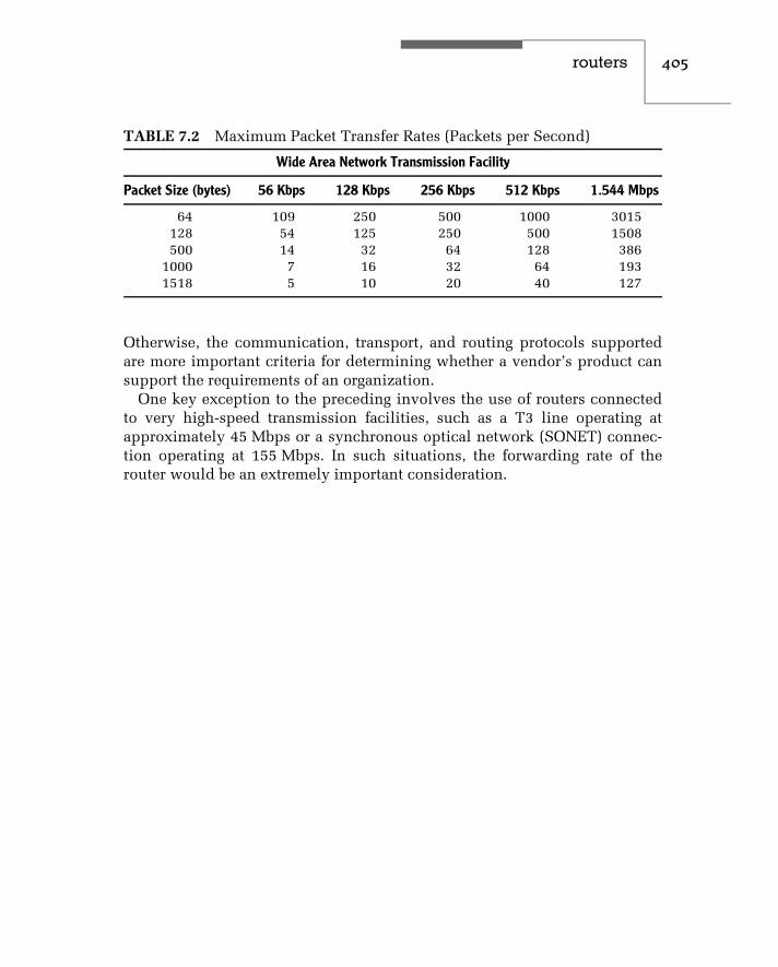
routers 405
TABLE 7.2 Maximum Packet Transfer Rates (Packets per Second)
Wide Area Network Transmission Facility
Packet Size (bytes) 56 Kbps 128 Kbps 256 Kbps 512 Kbps 1.544 Mbps
64 109 250 500 1000 3015128 54 125 250 500 1508500 14 32 64 128 386
1000 7 16 32 64 1931518 5 10 20 40 127
Otherwise, the communication, transport, and routing protocols supportedare more important criteria for determining whether a vendor’s product cansupport the requirements of an organization.
One key exception to the preceding involves the use of routers connectedto very high-speed transmission facilities, such as a T3 line operating atapproximately 45 Mbps or a synchronous optical network (SONET) connec-tion operating at 155 Mbps. In such situations, the forwarding rate of therouter would be an extremely important consideration.


c h a p t e r e i g h t
Wireless EthernetThe purpose of this chapter is to make readers familiar with a relatively newmethod of constructing or expanding an Ethernet network using the ‘‘ether’’as the transmission media. Referred to as wireless Ethernet, the technologywe will examine in this chapter is also commonly known as wireless LANs,802.11 networks and ‘‘Wi-Fi,’’ with the latter a term used to denote wirelessfidelity, a new term used for fast wireless LAN technology that is a play ofwords on a stereo system.
8.1 Overview
The IEEE 802.11 standard for wireless LANs represents a base that has evolvedover the years. The original 802.11 standard dates to 1997 and resulted inthree physical layers being standardized to transport Ethernet frames overthe air. One physical layer is for infrared transmission, while the other twophysical layers provide support for radio frequency (RF) communicationsthrough the use of Frequency Hopping Spread Spectrum (FHSS) and DirectSequence Spread Spectrum (DSSS) that were originally developed to resistjamming in a military environment.
Figure 8.1 illustrates the architecture associated with the original IEEE802.11 standard in comparison with the lower two layers of the ISO OSIReference Model. In examining Figure 8.1 you will note that the media accesscontrol method used by the IEEE 802.11 standard is not the basic CSMA/CDaccess protocol used by wired Ethernet. Instead, a protocol referred to asCarrier Sense Multiple Access with Collision Avoidance (CSMA/CA) is used.Later in this chapter we will turn our attention to how CSMA/CA operates.
The original IEEE 802.11 standard supports operations at either 1 Mbps or2 Mbps under each of the three physical layers. Recognizing that infraredis rarely used and data rates of 1 Mbps and 2 Mbps are not sufficient formany modern applications in a shared over-the-air environment resulted in
407

408 c h a p t e r e i g h t
ISO OSIReference Model IEEE 802.11 layers
Datalink
layer
Logical link control
Media access control (CSMA/CA)
Physicallayer FHSS DSSS IR
Legend:
FHSSDSSSIR
Frequency Hopping Spread SpectrumDirect Sequence Spread SpectrumInfrared
Figure 8.1 IEEE 802.11 architecture.
several additions to the IEEE standard. One addition was the IEEE 802.11bspecification, which extended the operating rate of DSSS to 5.5 Mbps and11 Mbps and which represented the most popular type of wireless LANwhen this book revision occurred. Both the basic 802.11 and the 802.11bspecifications operate in the 2.4 GHz unlicensed Industrial Scientific andMedical (ISM) band. While the Federal Communications Commission (FCC)in the U.S. regulates the maximum power and transmission method, the factthat the ISM band is unlicensed means that a user does not have to obtain alicense to use equipment in that frequency band.
A second addendum to the IEEE 802.11 standard is the 802.11a specification.This specification defines the use of a multi-carrier frequency transmissionmethod in the 5 GHz ISM band. The multi-carrier frequency method is referredto as orthogonal frequency division multiplexing (OFDM), which results ina large number of carriers being used, each of which operates at a low datarate, but cumulatively they support a high data rate up to 54 Mbps. Becausehigher frequencies attenuate more rapidly than lower frequencies, the range of802.11a-compatible devices is significantly less than that of 802.11b devices.This results in a requirement to install additional access points to obtain thesame area of wireless LAN coverage and increases the cost of a very high speedwireless LAN. Because many network operators require more speed than that
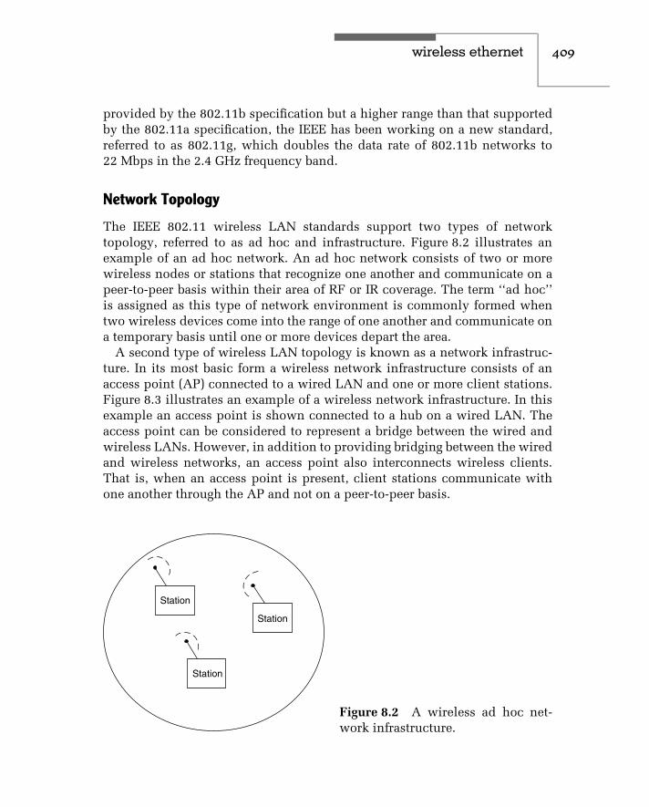
wireless ethernet 409
provided by the 802.11b specification but a higher range than that supportedby the 802.11a specification, the IEEE has been working on a new standard,referred to as 802.11g, which doubles the data rate of 802.11b networks to22 Mbps in the 2.4 GHz frequency band.
Network Topology
The IEEE 802.11 wireless LAN standards support two types of networktopology, referred to as ad hoc and infrastructure. Figure 8.2 illustrates anexample of an ad hoc network. An ad hoc network consists of two or morewireless nodes or stations that recognize one another and communicate on apeer-to-peer basis within their area of RF or IR coverage. The term ‘‘ad hoc’’is assigned as this type of network environment is commonly formed whentwo wireless devices come into the range of one another and communicate ona temporary basis until one or more devices depart the area.
A second type of wireless LAN topology is known as a network infrastruc-ture. In its most basic form a wireless network infrastructure consists of anaccess point (AP) connected to a wired LAN and one or more client stations.Figure 8.3 illustrates an example of a wireless network infrastructure. In thisexample an access point is shown connected to a hub on a wired LAN. Theaccess point can be considered to represent a bridge between the wired andwireless LANs. However, in addition to providing bridging between the wiredand wireless networks, an access point also interconnects wireless clients.That is, when an access point is present, client stations communicate withone another through the AP and not on a peer-to-peer basis.
Station
Station
Station
Figure 8.2 A wireless ad hoc net-work infrastructure.

410 c h a p t e r e i g h t
Clientstation
Accesspoint
Basic service area
Wired hub/switch
Figure 8.3 A wireless network infrastructure contains at least one accesspoint and one wireless station, referred to as a Basic Service Set.
When two or more mobile nodes come together to communicate or if onemobile client comes into close proximity to an access point, this action resultsin the formation of a Basic Service Set (BSS). Each BSS has an identificationthat typically corresponds to the 48-bit MAC address of the wireless networkadapter card. That identification is referred to as a Basic Service Set Identifi-cation (BSSID) and the area of coverage within which members of a BSS cancommunicate is referred to as a Basic Service Area (BSA).
When wiring an office, college campus or government agency, you willmore than likely need to install multiple access points. When this is done, thebasic service areas of coverage from multiple Basic Service Sets form what isreferred to as an Extended Service Set (ESS). The wired LAN infrastructurefunctions as a distribution system, which enables clients to roam and beserviced by different APs. Figure 8.4 illustrates an Extended Service Setformed by the use of two access points interconnected by a wired LAN usedas a Distribution System (DS). Each BSS within a DS is said to be operating inan infrastructure mode.
In examining Figure 8.4 it should be noted that the Basic Service Sets mayor may not overlap. In addition, each station associates itself with a particularaccess point based upon selecting the one with the greatest received signalstrength. Each access point in the Extended Service Set will have an ESSID(Extended Service Set Identifier) programmed into it. The ESSID can beconsidered to represent the subnet the access point is connected to. You can

wireless ethernet 411
Accesspoint
Accesspoint
Hub
Hub
Hub
ClientBSS-1BSS-2
Client Client
ESS
Server
Distributionsystem
Legend:BSS Basic Service Set
ESS Extended Service Set
Figure 8.4 An extended service set consists of one or more basic service setsconnected via a distribution system.
also program the ESSID into a station, which then requires it to connect to alike programmed access point.
When creating an extended service set it is also important to considerthe frequency of operation of each access point. This is due to the need tominimize the overlapping of frequency use by adjacent access points. BecauseFHSS and DSSS operating access points have different restrictions concerningfrequency overlap, you must also consider the transmission scheme usedwhen you design a large wireless infrastructure.
Roaming
In examining Figure 8.4 note that the movement of a client from BSS-1 to BSS-2 or vice versa represents a roaming action. Although IEEE 802.11 wirelessLANs support roaming, a wireless operational LAN environment is commonlya fixed-location environment in comparison to cellular telephones, which areused anywhere from a reception area, to the office, and even in the powderroom. Thus, while 802.11 wireless LANs support roaming, the actual degreeof this activity is limited in comparison to a cellular telephone.
412 c h a p t e r e i g h t
As a mobile client moves from one access-point service area to another, amechanism is required for one AP to drop the user while the other beginsservicing the user. A mobile client will typically monitor the signal-to-noiseratio (SNR) as it moves and, if required, scan for available access pointsand connect to a desired AP. APs periodically transmit a beacon frame thatenables clients to note the presence of one or more APs and select theone with the best SNR. However, the actual method used depends upona vendor’s implementation method. For example, in a Cisco wireless LANroaming environment a client will become associated with a new access pointwhen three conditions occur. First, the signal strength of the new accesspoint must be at least 50 percent. Second, the percentage of time the client’stransmitter is active is less than 20 percent of the present access point. Thethird condition requires the number of users on the new access point to befour fewer than on the present access point. If the first two conditions are notmet, then the client will not change access points regardless of the number ofusers associated with the AP.
Physical Layer Operations
As discussed earlier in this chapter, the original IEEE 802.11 wireless LANstandard supports a choice of three physical layers — infrared and two radio-frequency layers. The infrared physical layer is based upon the use of pulseposition modulation (PPM) at peak data rates of 1 Mbps, with an optional2 Mbps rate. Because infrared is limited to use within a single room withoutbarriers, its use is severely limited. In fact, this author is not aware ofany infrared-based 802.11 LANs. Because of this, in this section we willfocus our attention upon the RF physical layers. Both Frequency HoppingSpread Spectrum (FHSS) and Direct Sequence Spread Spectrum operate inthe 2.4 GHz ISM band, which represents a worldwide-recognized unlicensedband. However, it should be noted that the actual frequencies for the 2.4 GHzband can vary from country to country, as noted in Table 8.1.
FHSS
Under Frequency Hopping Spread Spectrum data is transmitted for a shortduration, referred to as dwell time at a single frequency. At the end of that timeduration the transmitter shifts to a new frequency and resumes transmission.Thus, a FHSS system uses narrow-band data transmission but changes itsfrequency periodically to create a wide-band transmission system.
Figure 8.5 illustrates an example of how an FHSS system hops for predefinedtime intervals using different center frequencies based upon a predefined

wireless ethernet 413
TABLE 8.1 2.4 GHz ISM Frequency Allocation
Region Allocated Frequency
United States 2.400–2.4835
Europe (except France/Spain) 2.400–2.4835
Japan 2.4710–2.4970
France 2.4465–2.4835
Spain 2.4450–2.4750
Time
f5
f3
f2
f1
f0
f4
Freq
uenc
y
Figure 8.5 A frequency hopping spread spectrum system hops at a fixed timeinterval, known as the dwell time, around a wide band using different centerfrequencies in a predefined sequence.
algorithm. By only dwelling at one frequency for a short time duration,an FHSS system can alleviate the effect of narrow-band noise occurring inportions of the transmission band.
Although a military system based upon FHSS keeps the algorithm usedfor hopping a secret, in the wonderful world of wireless LANs the hoppingsequence is well known. In fact, both the frequencies at which hopping occursas well as the number of hops within an assigned ISM band are commonly

414 c h a p t e r e i g h t
regulated to prevent a wireless LAN from interfering with other electronicequipment. In the United States FHSS uses 79 channels, each 1 MHz wide. InJapan, the number of channels is reduced to 23. For both locations channelsare selected according to a pseudo-random selection algorithm that requiresa dwell time of 20 ms per channel and all channels to be used prior to beingable to reuse a channel. Under the IEEE 802.11 standard 78 different hoppingsequences are defined. Each hopping sequence is referred to as a channel,which can cause a degree of confusion if you scan the standard withoutnoting this relationship. At the physical layer FHSS uses two- or four-levelGaussian Frequency Shift Keying (GFSK) modulation. Under two-level FSKmodulation each bit is encoded by the transmission of a distinct frequencyfrom two available frequencies. Thus, the bit rate is the same as the baudor signaling rate and the 1 MHz bandwidth used for each short transmissionsupports a data rate of 1 Mbps. When four-level GFSK is used, each pair (dibit)of bits is encoded into one of four frequencies. Thus, the bit rate is twice thebaud rate, resulting in a data rate of 2 Mbps. The term ‘‘Gaussian’’ prefixesFSK because the wave form is Gaussian filtered.
Now that we have an appreciation for FHSS let us turn our attention to howDSSS operates.
DSSS
Under Direct Sequence Spread Spectrum (DSSS) a spreading code is usedto spread each bit to be transmitted such that a number of bits representingeach bit are actually transmitted. The spreading code used under the 802.11standard is referred to as a Barker code and its use results in each bit beingreplaced by 11 bits. At 1 Mbps Differential Binary Phase Shift Keying (DBPSK)is used for modulation, resulting in each bit being represented by one of twopossible phase changes. Because 11 bits replace each data bit, the resultingsignal is spread over 11 MHz. At 2 Mbps Differential Quadrature Phase ShiftKeying (DQPSK) is employed as the modulation method, which results intwo bits being encoded into one phase change. When this modulation methodis used, the bit rate becomes twice the baud rate, which results in a 2 Mbpsdata rate.
Table 8.2 gives an example of DSSS coding using a five-bit sequences froma pseudo-random bit generator. Note that data for transmission is simplylogically modulo-2 added to obtain the data stream to be modulated.
Upon demodulation the same pseudo-random bit sequence is modulo-2subtracted to obtain the original setting of the bit that was spread. If atransmission error occurs, the receiver simply selects the most popular bit

wireless ethernet 415
TABLE 8.2 DSSS Bit Spreading Example using a Five-bitSpreading Code
Data bits 1 0
Five-bit spreading code 10110 01001
Modulo-2 addition (data to be modulated) 01001 01001
Demodulated data 01001 01001
Five-bit spreading code 10110 01001
Modulo-2 subtraction 11111 00000
setting. That is, a if a five-bit spreading code was used and as a result of themodulo-2 subtraction process at the receiver, three bits were set to a value of1 while two were set to a value of 0, the bit setting would be assumed to be 1.
Similar to FHSS, the use of DSSS can vary by location. Under the IEEE802.11 standard the use of 13 DSSS channels is defined for transportingan 11-bit Barker-coded 22 MHz signal. For operation in the United Statesthe 802.11 standard defines the use of 11 independent channels. AlthoughEurope and many Asian countries permit the use of 13 channels, in Japan thesmall amount of available bandwidth (see Table 8.1) results in the support ofa single channel. Table 8.3 lists the carrier-frequency channel assignments.As previously noted, depending upon the physical location of a DSSS systema subset of available channels may be required to be used.
In the United States and Europe DSSS channel definitions permit threefrequency-isolated channels available for co-location. An example of chan-nel co-location is illustrated in Figure 8.6. This frequency isolation enablesorganizations to operate up to three DSSS functioning access points withinclose proximity to one another without one access point interfering withanother.
High-Speed Wireless LANs
There are two extensions to the basic IEEE 802.11 standard for which equip-ment had reached the market when this book revision was performed. Thoseextensions are the IEEE 802.11b specification, for which equipment conform-ing to that standard dominates the market, and the IEEE 802.11a specification.Although the modulation methods differ for each method, they use the same

416 c h a p t e r e i g h t
TABLE 8.3 2.4 GHz DSSSChannels
Channel Frequency (MHz)
1 2412
2 2416
3 2422
4 2427
5 2432
6 2437
7 2442
8 2447
9 2452
10 2457
11 2462
12 2467
13 2473
2.4 GHz Frequency 2.4835 GHz
Figure 8.6 DSSS supports up to three non-overlapping channels in the2.4 GHz band.
access protocol, a topic we will focus our attention upon once we obtain anappreciation of the two extensions to the basic IEEE 802.11 standard.
802.11b
Under the 802.11b extension to the IEEE 802.11 standard the data rate wasincreased to 5.5 Mbps and 11 Mbps under DSSS operations. At the higher data

wireless ethernet 417
rates of 5.5 Mbps and 11 Mbps DSSS transmitters and receivers use differentpseudo-random codes. Collectively, the higher modulation rates are referredto as Complementary Code Keying (CCK).
802.11a
Under the 802.11a extension to the IEEE 802.11 standard orthogonal frequencydivision modulation (OFDM) is employed in the 5 GHz frequency band. UnderOFDM multiple-modulated carriers are used instead of a single carrier, asillustrated in Figure 8.7. Here each modulated signal is orthogonal to theother modulated signals.
The term orthogonal describes the axis of the signals and the fact that they donot interfere with one another. Because multiple signals are transmitted by asingle user, the carriers can be said to be multiplexed. Thus, the transmissionof multiple carriers at 90 degree angles to one another was given the termOFDM. However, if you are familiar with the operation of DSL modems orone of the first 9600 BPS analog dial modems, you are also probably aware ofthe term ‘‘multitone’’ used to denote the use of multiple carriers. Thus, OFDMcan be considered to represent a multitone transmission scheme.
Under the 802.11a standard 48 data and four pilot carriers or a total of52 carriers are transmitted within a 20 MHz channel. This action makes useof the three blocks or bands of frequency allocated by the FCC for unlicensedoperations in the 5 GHz band. A 200 MHz band from 5.15 GHz to 5.35 MHzhas two sub-bands. The first 100 MHz in the lower section is restricted to amaximum power output of 50 mW, while the second 100 MHz has a moregenerous 250 mW maximum power output. A third band at 5.725 MHz to5.825 MHz is designed for outdoor applications and supports a maximum of1 W of power output.
Because the 5 GHz band has almost four times the bandwidth of the ISMband, the developers of the 802.11a specification turned to OFDM to make
. . .
Frequency
Pow
er
Figure 8.7 Orthogonal frequency division multiplexing results in the trans-mission of multiple carriers, each modulating a small amount of data.

418 c h a p t e r e i g h t
better use of available bandwidth. As previously mentioned, each 20 MHzchannel consists of 48 data subchannels and four used for pilot tones anderror correction, with each subchannel approximately 300 kHz wide.
Several different modulation methods are supported under the 802.11astandard. Binary Phase Shift Keying (BPSK) is used to encode 125 kbps ofdata per channel, resulting in a 6 Mbps data rate. When Quadrature Phase ShiftKeying (PSK) is used, the amount of data encoded increases to 250 kbps perchannel, which results in a 12 Mbps data rate. A 16-level quadrature amplitudemodulation method that encodes four bits per signal change permits a datarate of 24 Mbps. At the ‘‘top end of the line’’ a 64-level QAM modulationmethod is supported. 64 QAM can operate encoding either 8 or 10 bits persignal change, permitting a maximum data rate of 1.125 Mbps per 300 Hzchannel. Because 48 data subchannels are supported per channel, this resultsin a maximum data rate of 54 Mbps.
Although the 802.11a specification supports a much higher data rate thanthe 802.11b specification, it is important to remember that higher frequenciesattenuate much more rapidly than lower frequencies. As a result of this, therange of 802.11a equipment is probably half that of 802.11b products, whichmeans the radius of coverage of an 802.11a access point will be one-fourththat of an 802.11b access point.
Access Method
Unlike wired Ethernet, which uses the CSMA/CD access protocol, wirelessEthernet LANs use what is referred to as a distributed coordination func-tion (DCF). DCF represents a modification of the Carrier Sense MultipleAccess/Collision Avoidance (CSMA/CA) protocol. Under the CSMA/CA pro-tocol each station listens to the air for activity of other users. If the channelit is tuned to is idle, the station can transmit. However, if the channel hasactivity, the station will wait until transmission ceases and then enter a ran-dom back-off procedure. This action is designed to prevent multiple stationsfrom seizing the channel immediately after the completion of an in-progresstransmission. Under the distribution coordination function access method aperiod of time referred to as the DCF interframe space (DIFS) determines ifa packet can be transmitted. That is, if the medium is sensed to be availablefor a duration of time that exceeds the DIFS, a packet can be immediatelytransmitted.
A second time interval that comes into play under the DCF access method isthe short interframe space (SIFS). Under the IEEE 802.11 standard a receivermust transmit a positive acknowledgement (ACK) to the transmitter when a

wireless ethernet 419
packet is received error free. An ACK will be transmitted after the SIFS, whichis of less duration than the DIFS. This ensures that an ACK is transmittedprior to any new frame being transmitted. If an ACK is not received within aperiod of time, the transmitter will assume the frame was corrupted and willre-transmit the frame at the first opportunity to do so.
Figure 8.8 illustrates the relationship of the DIFS and SIFS to the transmis-sion of data. At the top of the illustration the transmitting device is assumedto listen to the channel and observe no activity for at least one DCF InterframeSpace (DIFS) prior to transmitting a frame. The receiving device must thenwait one Short Interframe Space (SIFS) prior to acknowledging the frame.
A second device requiring the ability to transmit is shown in the lowerportion of Figure 8.8. This device is assumed to need to transmit a frame,but listens to the channel and hears the transmission of the first device orthe acknowledgement of the receiver. The time from the frame being placedonto the channel through the DIFS following the receiver’s ACK represents adeferred access time. Because a transmission was sensed to be in progress, thesecond device must wait a random period after the deferred access time. Thesecond transmitter sets an internal time to an integer number of slot times andobserves when the DIFS time expires. Upon the expiration of the DIFS timethe timer of the second transmitter decrements towards zero. If the channelis still available when the timer decrements to zero, the second station can
DataDIFS
DIFS
SIFS
ACK
Deferred access
Time
Contentionwindow
Nextdata
Slot times
Back offAfter defer
Transmittingstation A
Transmittingstation C
Receivingstation B
Legend:
DIFS DFC Interframe Space
SIFS Short Interframe Space
Figure 8.8 The CSMA/CA access protocol is based upon two key timers anda back-off algorithm.

420 c h a p t e r e i g h t
commence transmission. Otherwise, if the channel is used by another stationprior to the timer reaching zero, its setting is retained at its current value forfuture use.
The Hidden Node Problem
Because radio-frequency communications can be easily blocked by obstruc-tions, it becomes possible for one node to be placed in a situation where itdoesn’t hear another. When this situation occurs, another node would listento a channel and an obstruction hiding the transmission of another stationwould make the node think it is available for use when it is actually occupied.The result of this action would be a propagation of two radio waves that ata distant point collide, preventing other nodes from using the channel. Toreduce the probability of collisions, a derivative of the CSMA/CA protocolreferred to as Virtual Carrier Sense (VSC) is used by the 802.11 standard.Under VCS a station that needs to transmit information will first transmit aRequest to Send (RTS) frame. The RTS frame represents a relatively short con-trol frame that contains the source and destination address and the durationof the following transmission. The duration is specified in terms of the timefor the transmission of a frame carrying data and the acknowledgement of theframe by the receiver. The receiver responds to the RTS frame with a Clear ToSend (CTS) control frame that indicates the same time duration informationas contained in the RTS control frame.
A station that receives either an RTS or CTS control frame will set its virtualcarrier sense indicator for the duration of the transmission. The VSC indicatoris referred to as the Network Allocation Vector (NAV) by the 802.11 standardand serves as a mechanism to alert all other stations on the air to back off ordefer their transmission.
If a station transmitting an RTS frame does not receive a correspondingCTS frame within a predefined period of time, the originator will assume acollision has occurred. Then, the originator will listen to the channel and,upon noting it is free, transmit another RTS frame. Once a CTS frame isreceived, the originator will send a data frame. The receiver will then returnan ACK frame to acknowledge a successful transmission.
The use of RTS and CTS frames, while reducing the probability of collisionsoccurring at a receiver from a station ‘‘hidden’’ from the transmitter, addsoverhead to the media access operation. Due to this, most manufacturersdisable this option by default, requiring network managers to enable it onboth client stations and access points.

wireless ethernet 421
8.2 Frame Formats
Similar to wired Ethernet, where there is one basic frame format, wirelessLANs also have a basic data frame format. However, wireless LANs alsosupport two additional types of frames. One type, referred to as controlframes, was briefly mentioned when we discussed the hidden node. The thirdtype of frame supported by wireless LANs is management frames, which areused to exchange management information between stations at layer 2 butwhich are not forwarded to upper layers in the protocol suite.
Data Frame
Figure 8.9 illustrates the format of the MAC data frame which is used totransmit information between stations. This basic data frame contains ninefields, with two fields subdivided into additional fields. As we will note laterin this section, several fields from this frame are used in other types of frames.
In examining Figure 8.9, you will note that the 802.11 frame permits abody that can be up to 2312 bytes in length. Because the maximum lengthEthernet frame has a 1500-byte Information field, the wireless LAN framecan transport a maximum wired Ethernet frame. However, because the biterror rate on a radio link can considerably exceed that of a wired LAN, this
Framecontrol
Duration/ID
Address1
Address2
Address3
Address4
Sequencecontrol
Framebody CRC
Fragmentnumber
Sequencenumber
Bytes
2 2 6 6 6 2 6 0−2312 6
Protocolversion Type Subtype To
DsFromDs
Morefrag
PwrMgt
Moredata WEP RsvdRetry
2 2 4 1 1 1 1 1 1 1 1
Figure 8.9 The basic 802.11 MAC data frame format.

422 c h a p t e r e i g h t
means that the probability of a bit error increases as the length of the wirelessframe increases. To compensate for this higher wireless bit error probability,a simple fragmentation and re-assembly mechanism is included in the 802.11standard and we will shortly examine this. To obtain an appreciation of themanner by which the MAC data frame conveys information, let us turn ourattention to the use of the fields and subfields in the frame.
Control Field
The 16-bit control field consists of 11 subfields, with eight representing one-bit fields whose setting indicates whether a specific feature or function isenabled or disabled. In this section we will examine the use of each subfieldin the order they appear in the control field.
Protocol Version Subfield
The two-bit Protocol Version subfield provides a mechanism to identify theversion of the IEEE 802.11 standard. In the initial version of the standard thevalue of the Protocol Version subfield is set to 0.
Type and Subtype Subfields
The Type and Subtype subfields consist of six bits that identify the type offrame and its function or subtype. Bits 2 and 3 denote the type of frame.Although the use of two bits permits four types of frames to be defined,at the present time only three types are defined — management, control,and data. The Subtype subfield consists of bits 4 through 7 and defines thefunction of a specific type of frame. Table 8.4 lists the Type and Subtypesubfield values to include a description of what the values of the y-bitpositions indicate.
In examining the entries in Table 8.4 note that the previously mentionedRTS, CTS and ACK functions represent the frames we briefly described earlierand the format of which we will investigate later in this section. The Beaconframe represents the frame an access point periodically generates to indicateits presence to stations while probe frames are used to query the status ofa device.
ToDS
This 1-bit field is set to a value of 1 when the frame is addressed to an accesspoint for forwarding to the distribution system. Otherwise, the bit is set to avalue of 0.

wireless ethernet 423
TABLE 8.4 Type and Subtype Values
Type Valueb3 b2 Type Description
Subtype Valueb7 b6 b5 b4 Subtype Description
00 Management 0000 Association Request
00 Management 0001 Association Response
00 Management 0010 Association Request
00 Management 0011 Association Response
00 Management 0100 Probe Request
00 Management 0101 Probe Response
00 Management 0110–0111 Reserved
00 Management 1000 Beacon
00 Management 1001 ATM
00 Management 1010 Disassociation
00 Management 1011 Authentication
00 Management 1100 De-authentication
00 Management 1101–1111 Reserved
01 Control 0000–0001 Reserved
01 Control 1010 PS-Poll
01 Control 1011 RTS
01 Control 1100 CTS
01 Control 1101 ACK
01 Control 1110 CF End
01 Control 1111 CF End + CF-ACK
10 Data 0000 Data
10 Data 0001 Data + CF-ACK
10 Data 0010 Data + CF-Poll
10 Data 0011 Data + CF-ACK + CF-Poll
10 Data 0100 Null Function (no data)
10 Data 0101 CF-ACK (no data)
10 Data 0111 CF-Poll (no data)
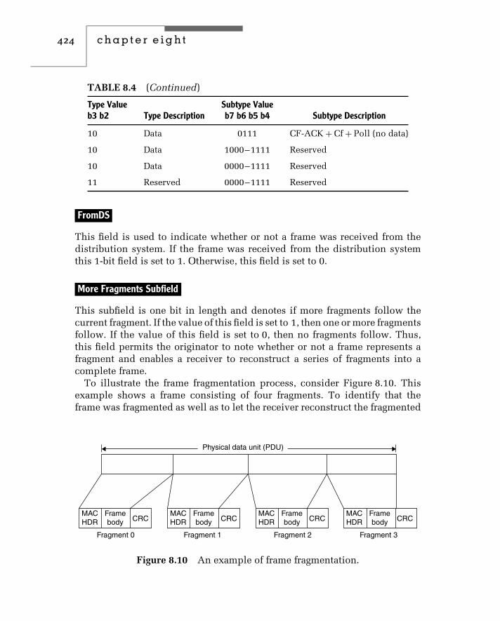
424 c h a p t e r e i g h t
TABLE 8.4 (Continued)
Type Valueb3 b2 Type Description
Subtype Valueb7 b6 b5 b4 Subtype Description
10 Data 0111 CF-ACK + Cf + Poll (no data)
10 Data 1000–1111 Reserved
10 Data 0000–1111 Reserved
11 Reserved 0000–1111 Reserved
FromDS
This field is used to indicate whether or not a frame was received from thedistribution system. If the frame was received from the distribution systemthis 1-bit field is set to 1. Otherwise, this field is set to 0.
More Fragments Subfield
This subfield is one bit in length and denotes if more fragments follow thecurrent fragment. If the value of this field is set to 1, then one or more fragmentsfollow. If the value of this field is set to 0, then no fragments follow. Thus,this field permits the originator to note whether or not a frame represents afragment and enables a receiver to reconstruct a series of fragments into acomplete frame.
To illustrate the frame fragmentation process, consider Figure 8.10. Thisexample shows a frame consisting of four fragments. To identify that theframe was fragmented as well as to let the receiver reconstruct the fragmented
Framebody CRC
MACHDR
Framebody CRC
MACHDR
Framebody CRC
MACHDR
Framebody CRC
MACHDR
Fragment 0 Fragment 1 Fragment 2 Fragment 3
Physical data unit (PDU)
Figure 8.10 An example of frame fragmentation.

wireless ethernet 425
frame, fragments 0, 1 and 2 would have their More Fragments subfield valuesset to 1 in the MAC header in each frame.
Under the IEEE 802.11 standard the fragmentation process is based upon asimple send-and-wait algorithm. Under this algorithm the transmitting stationcannot send a new fragment until it either receives an ACK for the priorsegment or decides that the fragment was retransmitted a predefined numberof times and drops the entire frame.
Retry Subfield
The value of this one-bit subfield is set to 1 to indicate that the frame is afragment representing the retransmission of a previously transmitted fragment.The receiving station uses this field to recognize duplicate transmissions thatcan occur if an ACK frame is lost.
Power Management Subfield
The IEEE 802.11 standard defines two power modes that a station can bein — Power Save or Active. A station that is Active when transmitting a framecan change its power status from Active to Power Save.
The Power Management setting is used by access points, which continu-ously maintain a record of stations working in the Power Saving mode. Theaccess point will buffer frames addressed to those stations until either theyspecifically request them via the transmission of a polling request or theychange their power status.
A second technique employed to transmit buffered frames to a station in itsPower Save mode of operation is obtained through the use of Beacon frames.An access point periodically broadcasts frames that includes informationconcerning which stations operating in a Power Saving mode have framesbuffered by the access point. The station uses the Beacon of information towake up and remains in an Active power mode while it transmits a pollingmessage to the AC to retrieve those buffered frames.
More Data Subfield
The purpose of the More Data subfield is to indicate if there are more framesfollowing the current frame. This one-bit field is set by an access pointto indicate that there are more frames buffered to a particular station. Thedestination station will use this bit setting to decide if it should continuepolling or if it should change its power management state.

426 c h a p t e r e i g h t
WEP Subfield
The Wired Equivalent Privacy (WEP) subfield indicates whether or not thebody of the frame is encrypted. WEP uses the RC4 encryption algorithm, whichis a stream cipher. As a reminder, a stream cipher operates by expanding ashort key into an infinite pseudo-random key stream. The transmitter XORs(modulo-2 adds) the key stream to the plain text, resulting in the generationof encrypted ciphertext. The receiver uses the same key to generate the samesequence of pseudo-random bits, which are then modulo-2 subtracted fromthe received ciphertext to reconstruct the plain text.
As we will note later in this chapter when we examine some wirelessequipment configurations, the WEP algorithm uses a pseudo-random numbergenerator that is initialized by a 40-bit key. Through the use of a 40-bit keyand a 24-bit initialization vector a 64-bit key is generated that, according tomany reports, is relatively easy to break. Although some products support128-bit WEP keys, papers have been published that appear to indicate that theextended key is also susceptible to being broken. Because only one bit is usedin the field to indicate whether WEP is enabled or disabled, all stations withina BSS must be configured similarly with respect to WEP. That is, either allstations and the access point within a BSS must have WEP disabled or theymust be configured to use the same key.
Order Subfield
The last position in the Control field is the one-bit Order subfield. The settingof this bit is used to indicate that the frame is being transmitted using theStrictly Ordered service class. This bit position was added to accommodate theDEC LAT protocol, which cannot accept change of ordering between unicastand multicast frames. Because the DEC LAT protocol is not exactly a popularone for the vast majority of wireless applications, this subfield is ignored.
Now that we have an appreciation of the subfields within the control field,let us continue our tour of the MAC data frame.
Duration/ID Field
This two-byte field indicates either the station identification (ID) or theduration in microseconds requested to transmit a frame and its interval to thenext frame. The actual interpretation of the value stored in this field dependsupon the type of the frame. In a Power-Save Poll message this field indicatesthe station ID. In all other types of frames the value in this field indicates theduration in milliseconds requested to transmit a frame and its interval to thenext frame.
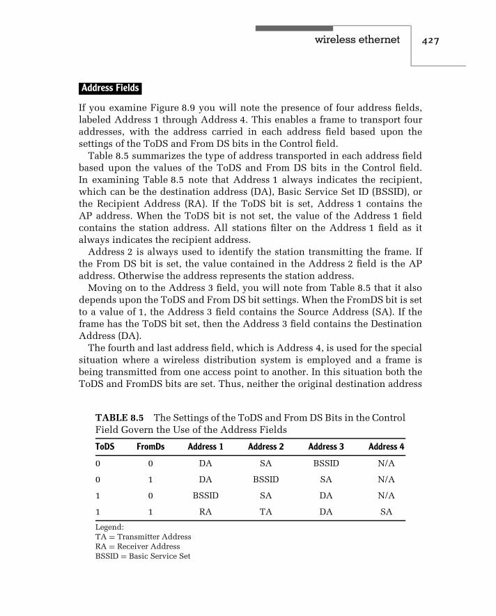
wireless ethernet 427
Address Fields
If you examine Figure 8.9 you will note the presence of four address fields,labeled Address 1 through Address 4. This enables a frame to transport fouraddresses, with the address carried in each address field based upon thesettings of the ToDS and From DS bits in the Control field.
Table 8.5 summarizes the type of address transported in each address fieldbased upon the values of the ToDS and From DS bits in the Control field.In examining Table 8.5 note that Address 1 always indicates the recipient,which can be the destination address (DA), Basic Service Set ID (BSSID), orthe Recipient Address (RA). If the ToDS bit is set, Address 1 contains theAP address. When the ToDS bit is not set, the value of the Address 1 fieldcontains the station address. All stations filter on the Address 1 field as italways indicates the recipient address.
Address 2 is always used to identify the station transmitting the frame. Ifthe From DS bit is set, the value contained in the Address 2 field is the APaddress. Otherwise the address represents the station address.
Moving on to the Address 3 field, you will note from Table 8.5 that it alsodepends upon the ToDS and From DS bit settings. When the FromDS bit is setto a value of 1, the Address 3 field contains the Source Address (SA). If theframe has the ToDS bit set, then the Address 3 field contains the DestinationAddress (DA).
The fourth and last address field, which is Address 4, is used for the specialsituation where a wireless distribution system is employed and a frame isbeing transmitted from one access point to another. In this situation both theToDS and FromDS bits are set. Thus, neither the original destination address
TABLE 8.5 The Settings of the ToDS and From DS Bits in the ControlField Govern the Use of the Address Fields
ToDS FromDs Address 1 Address 2 Address 3 Address 4
0 0 DA SA BSSID N/A
0 1 DA BSSID SA N/A
1 0 BSSID SA DA N/A
1 1 RA TA DA SA
Legend:TA = Transmitter AddressRA = Receiver AddressBSSID = Basic Service Set

428 c h a p t e r e i g h t
nor the original source address is applicable and Address 4 is then limited toidentifying the source of the wireless DS frame.
Sequence Control Field
The two-byte Sequence Control field provides a mechanism to represent theorder of different fragments that are part of a frame. As previously illustratedin Figure 8.9, the Sequence Control field consists of two subfields — FragmentNumber and Sequence Number. Those subfields are used to define the frameand the number of the fragment that is part of a frame.
Frame Body Field
The Frame Body field is the field that transports information between stations.As indicated in Figure 8.9, this field can vary in length up to 2312 bytes.
CRC Field
The last field in the MAC data frame is the CRC field. This field is four bytesin length and is used to contain a 32-bit CRC.
Now that we have an appreciation of the composition of the MAC dataframe, let us turn our attention to the composition of several control frames.
Control Frames
As previously noted in this chapter, the IEEE 802.11 standard defines theuse of several types of control frames that govern access to the media aswell as provide acknowledgement of a received frame. In this section we willexamine the format and utilization of three control frames — RTS, CTS andACK. Figure 8.11 indicates the format of each frame.
RTS Frame
The RTS and CTS frames have a similar format, with the MAC headercontained in the Frame Control field for each frame. Concerning the RTS frame,the Receiver Address represents the address of the wireless network stationthat is the intended immediate recipient of the next data or managementframe. The transmitted address (TA) represents the address of the stationtransmitting the RTS frame, while the Duration field contains the time inmicroseconds required to transmit the next data or management frame plusone CTS frame, one ACK frame, and three interval periods between frames.

wireless ethernet 429
Framecontrol
Framecontrol
Receiveraddress
Receiveraddress
Duration
Duration
CRC
CRC
Transmitteraddress
Bytes
Bytes
2 2 6
2 2 6 4
6 4
ACK
RTS and CTS
Figure 8.11 Common control frames.
Because the RTS frame is generated by a transmitter requesting access to themedium, it will be responded to by a CTS frame.
CTS Frame
The CTS frame has the same format as the RTS frame and the entry of datain the fields of the frame forms a relationship between the two. That is, theReceiver Address (RA) of a CTS frame is copied from the Transmitter Address(TA) field of the received RTS frame. The value of the duration field is obtainedfrom the duration field of the previously received RTS frame less the time, inmicroseconds, required to transmit the frame and the Short Interframe Space(SIFS) interval. The Receiver Address and Transmitter Address for both RTSand CTS frames are 48 bits in length and represent the address length used byIEEE 802.3 wired LANs.
ACK Frame
A third commonly used control frame is the ACK frame, the format of whichis shown in the lower portion of Figure 8.11.
Similar to the CTS frame, several fields in the ACK frame contain valuesbased upon a previously received frame. For example, the Receiver Addressfield value of the ACK frame is copied from the Address 2 field of thepreviously received frame that the ACK acknowledges. A second example offield relationships between frames concerns the setting of the More Fragmentbit in the Frame Control field of the previous frame. If that bit was set to 0,the Duration field in the ACK frame is set to 0. Otherwise, the Duration fieldvalue is obtained from the Duration field of the previous frame minus the timein microseconds required to transmit the ACK frame and its SIFS interval.

430 c h a p t e r e i g h t
Management Frames
As noted in Table 8.4, there are 10 defined management frames. Two of themore popular types of management frames are Beacon and Probe frames, bothof which we will examine in this section.
The Beacon Frame
Figure 8.12 illustrates the basic format of the body of a Beacon and Probeframe as well as the Capability field included in each frame.
When a client comes in range of an access point it will hear the periodicbroadcast of Beacon frames transmitted by the access point to indicate itspresence. In addition to notifying stations of the presence of the access point,Beacon frames provide all stations within a BSS with synchronization infor-mation and power management support. Concerning the latter, as previouslynoted clients can be in a Power Save or Awake mode. In the Awake modestations are fully powered on and can receive frames at any time. If a nodegoes into a Power Save mode it must first inform the access point. Once inthe Power Save mode a station will periodically wake up to listen for beaconsthat indicate that the AP has queued messages for it.
In examining the Parameter Set shown in Figure 8.12, note that a particularparameter, such as FH, is only present if a station is using the applicablephysical layer. The IBSS parameter set is only present within Beacon framesgenerated by stations within an IBSS, while TIM information is only presentwithin Beacon frames generated by an access point. Here the term IBSSreferences an independent basic service set, which is a single BSS thatoperates independently within an area.
Probe Response Frame
The Beacon can be considered to represent an advertisement that tells stationsan access point is alive. If a station notes the presence of a Beacon frame andwants to join an existing cell it will transmit a Probe Request frame to anaccess point.
The response to a Probe Request is conveyed by a Probe Response frame,whose body is shown in the middle portion of Figure 8.12. Note that the bodyis similar to the Beacon frame body; however, the TIM information element isnot present.
Capability Information Field
Within both Beacon and Probe frames is a capability information field. Thisfield consists of two bytes, with the first used to define eight one-bit subfields

wireless ethernet 431
Info
rmat
ion
Bea
con
fram
e
Tim
esta
mp
Cap
abili
tyS
SID
IBS
ST
IMB
eaco
nin
terv
alS
uppo
rted
rate
s
Par
amet
er s
et
FH
DS
EF
Info
rmat
ion
Pro
be r
espo
nse
Tim
esta
mp
Cap
abili
tyin
form
atio
nS
SID
Bea
con
inte
rval
Sup
port
edra
tes
IBS
Spa
ram
eter
set
Par
amet
er s
et
FH
DS
EF
Cap
abili
ty in
form
atio
n fie
ld
B0
B1
B2
B3
B4
B5
B6
B7
B15
ES
SIB
SS
Priv
acy
PB
CC
Res
erve
dC
Fpo
llabl
eC
F p
oll
requ
est
Sho
rtpr
eam
ble
Cha
nnel
agili
ty
Fig
ure
8.12
Bea
con
and
pro
befr
ame
bod
ies.
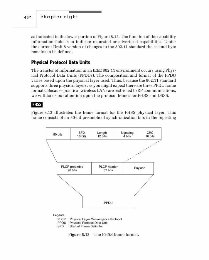
432 c h a p t e r e i g h t
as indicated in the lower portion of Figure 8.12. The function of the capabilityinformation field is to indicate requested or advertised capabilities. Underthe current Draft 8 version of changes to the 802.11 standard the second byteremains to be defined.
Physical Protocol Data Units
The transfer of information in an IEEE 802.11 environment occurs using Phys-ical Protocol Data Units (PPDUs). The composition and format of the PPDUvaries based upon the physical layer used. Thus, because the 802.11 standardsupports three physical layers, as you might expect there are three PPDU frameformats. Because practical wireless LANs are restricted to RF communications,we will focus our attention upon the protocol frames for FHSS and DSSS.
FHSS
Figure 8.13 illustrates the frame format for the FHSS physical layer. Thisframe consists of an 80-bit preamble of synchronization bits in the repeating
80 bits
Legend:PLCPPPDUSFD
Physical Layer Convergence ProtocolPhysical Protocol Data UnitStart of Frame Delimiter
SFD16 bits
PLCP preamble96 bits
PayloadPLCP header32 bits
PPDU
Length12 bits
CRC16 bits
Signaling4 bits
Figure 8.13 The FHSS frame format.

wireless ethernet 433
pattern of 0101. . .01. This pattern is used for signal detection and is followedby a 16-bit Start of Frame Delimiter (SFD). The SFD field is followed by aPhysical Layer Convergence Procedure (PLCP) header, which includes threesubfields. The length subfield denotes the length of the payload in bytes, afour-bit Signaling field that denotes the operating rate and a 16-bit CRC that isused to detect errors in the header. Under FHSS, initial transmission occursat a 1 Mbps data rate until the signaling field value is read. As a refresher, a1 Mbps data rate is obtained by using two-level GFSK while a 2 Mbps datarate occurs through the use of four-level GFSK.
DSSS
In comparison to the FHSS frame format, the format for the DSSS frame isslightly more complex. That frame format, which is illustrated in Figure 8.14,uses a 144-bit Physical Layer Convergence Procedure (PLCP) preamble dividedinto a 128-bit sequence used for signal detection and a Start of Frame Delim-iter (SFD).
The PLCP header consists of four fields. Those fields include an eight-bitSignal field, which indicates the data rate. Currently this field supports four
128 bits
Legend:PLCPPPDU
Physical Layer Convergence ProtocolPhysical Protocol Data Unit
SFD16 bits
PLCP preamble144 bits
PayloadPLCP header48 bits
PPDU
Signal8 bits
Length16 bits
CRC16 bits
SERVICE8 bits
Figure 8.14 DSSS frame format.

434 c h a p t e r e i g h t
values that correspond to operating rates of 1, 2, 5.5, and 11 Mbps. Threebits in the Service field are used to support a high-rate extension, indicatingthe modulation method, if transmit frequency and symbol clocks are derivedfrom the same oscillator and if an extension to the Length field is in effect.Concerning the Length field, that 16-bit field indicates the number of bytesin the MAC layer Protocol data Unit (PDU). The fourth field is the CRC field,which protects the Signal, Service and Length fields.
8.3 Deployment
When considering the deployment of wireless LAN technology, there are fourkey hardware products you need to consider. Those products include wirelessPC network adapter cards, access points, a combined router–access point, anda bridge.
Wireless PC Network Adapter Cards
The purpose of the wireless PC network adapter card is to turn a computerinto a participant on a wireless LAN. There are three common form factors bywhich wireless LAN network adapter cards are fabricated. Those form factorsinclude manufacture as a Type II PCMCIA card (now referred to as a PC card),as a PCI adapter card designed for insertion into the system unit of a desktopcomputer, and as a self-contained unit. When fabricated as a self-containedunit, the network adapter includes a USB connector, which facilitates its usewith the growing number of computers manufactured with such ports insteadof legacy parallel and serial ports.
Figure 8.15 shows a picture of the SMC Networks EZ Wireless PC Card. Theleft portion of the card slides into a PC Card slot in a laptop or notebook.The dark area on the right of the card represents a self-contained antennathat protrudes from the card slot. This PC card is designed for use in an IEEE802.11b ad hoc or infrastructure network environment and supports DSSSradio frequency communications at 1, 2, 5.5, and 11 Mbps. As we will notelater in this chapter, this adapter supports wired equivalent privacy (WEP).
The installation of a wireless LAN adapter card or the cabling of a self-contained network adapter via a USB bus cable turns a computer into a wirelessLAN client or station. Once software drivers are installed, you can normallytailor the operation of the adapter card. Depending upon the manufacturer ofthe adapter card, you may be able to select an ad hoc or infrastructure modeof operation, enable or disable a power-saving mode of operation, select oneof 13 RF channels for DSSS operation, and enable or disable WEP. Typically,

wireless ethernet 435
Figure 8.15 The SMC networks EZ wireless PC card is designed for insertioninto a Type II PC slot in a notebook or laptop computer.
default values are selected for each option that minimize or eliminate theneed for user configuration; however, accepting default settings can result incertain problems. For example, the default setting for WEP is disabled, whichmeans that all transmission is in the clear, a topic we will examine later inthis chapter.
Access Point
A second network component associated with wireless LANs is designed tointerconnect wired and wireless LANs. That network component is the accesspoint, which functions as a bridge between wired and wireless LANs.
Figure 8.16 illustrates a dual-antenna access point manufactured by SMCNetworks. The use of dual antennas permits the device to select a strongerreceived signal at a particular point in time. This can be important, because ina wireless LAN environment transmitted signals will hit different objects thatresult in RF signals being reflected in different directions. Such reflectionsresult in a spread of signals being received over many paths, which is referredto as multipath transmission. Through the use of dual antennas it becomespossible to discriminate among reflected signals and select the most applicablesignal at a point in time.
The SMC Networks EZ Connect wireless access point shown in Figure 8.16has an operating range up to approximately 1800 feet. However, the exactrange that can be obtained, as well as the data rate, depends upon the numberof obstructions between a client and an access point. In an office environment
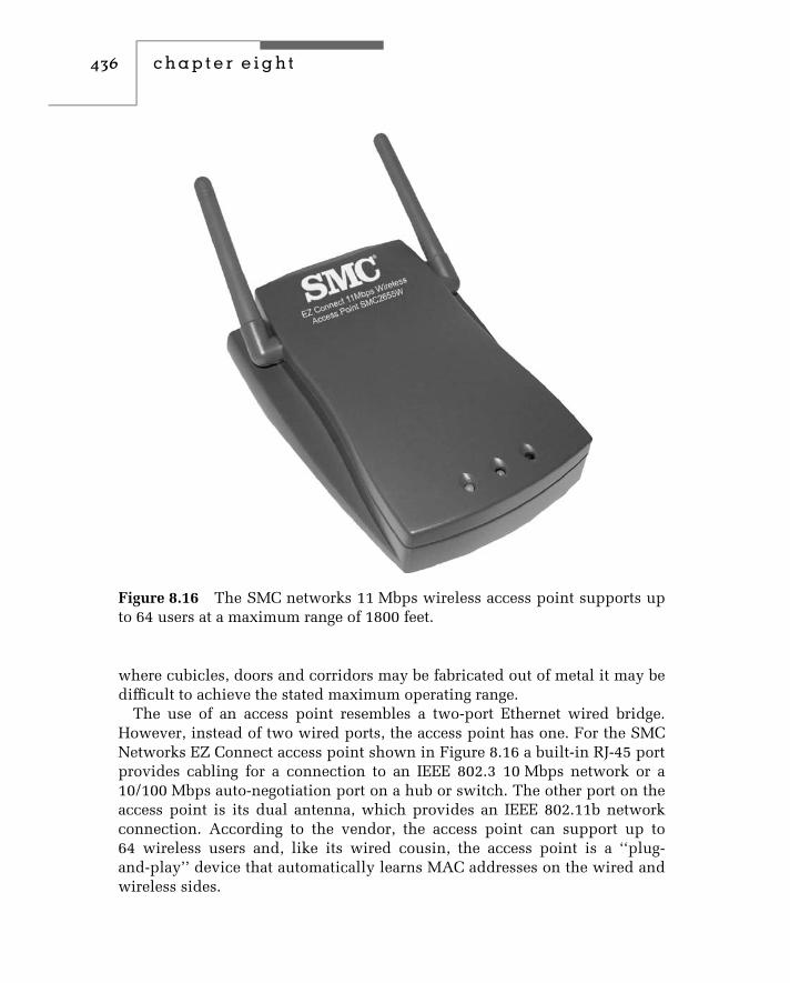
436 c h a p t e r e i g h t
Figure 8.16 The SMC networks 11 Mbps wireless access point supports upto 64 users at a maximum range of 1800 feet.
where cubicles, doors and corridors may be fabricated out of metal it may bedifficult to achieve the stated maximum operating range.
The use of an access point resembles a two-port Ethernet wired bridge.However, instead of two wired ports, the access point has one. For the SMCNetworks EZ Connect access point shown in Figure 8.16 a built-in RJ-45 portprovides cabling for a connection to an IEEE 802.3 10 Mbps network or a10/100 Mbps auto-negotiation port on a hub or switch. The other port on theaccess point is its dual antenna, which provides an IEEE 802.11b networkconnection. According to the vendor, the access point can support up to64 wireless users and, like its wired cousin, the access point is a ‘‘plug-and-play’’ device that automatically learns MAC addresses on the wired andwireless sides.

wireless ethernet 437
Combined Router/Access Point
Recognition of the growth in the use of DS Land Cable modems as a mechanismto access the Internet resulted in many hardware developers combining arouter and access point into a common housing. Through the use of thiscombined housing it becomes possible to extend a single Internet connectionfor use by multiple wireless clients.
Figure 8.17 illustrates the SMC Networks Barricade broadband router, whichcombines an access point, a router, and a three-port 10/100 Mbps Ethernetswitch into one housing. A fourth Ethernet port is used to provide a connectionto a DSL or cable modem. The use of this device or similar products fromother vendors provides a high degree of networking flexibility. For example,you could cable this device to a DSL or cable modem and use it to provideclients with wireless access to the Internet. As an alternative, you could cableone of the built-in switch ports to your existing wired hub or switch andobtain the capability for wireless clients to access the Internet or your wiredinfrastructure. In addition to supporting both wired and wireless LANs, theBarricade broadband router includes an asynchronous interface that enablesan ISDN dial connection to the Internet to be shared. Because wireless clientscommonly do not have their own printer, the Barricade also functions as aprint server and includes a printer interface on the device.
Network Address Translation
Because Internet Service Providers (ISPs) only issue one IP address per DSLor cable modem connection, a mechanism is required to share that address
Figure 8.17 The SMC Networks Barricade broadband router consists of anaccess point, a router and a three-port 10/100 Mbps Ethernet switch in acommon housing.

438 c h a p t e r e i g h t
among many wireless clients as well as any devices wired to the router. Themechanism used is referred to as Network Address Translation (NAT). TheSMC Networks Barricade router is similar to other products used by thisauthor in that it uses a Class C network address defined in RFC 1918 behindthe router as a mechanism for translating to and from the single IP addressassigned to the DSL or cable modem connections.
RFC 1918 defines Class A, B, and C address blocks that are reserved for pri-vate network use. Because two or more organizations can use those addresses,they are not unique and cannot be directly used on the Internet. However,they can be used internally to an organization and only require a translationmechanism to provide clients with the ability to access the Internet. Thattranslation mechanism is performed by the router by mapping each RFC 1918Class C IP address into a high-value TCP or UDP source port number but notaltering the single IP address allocated to the DSL or cable modem connection.When a response occurs, the source port value is returned as a destinationport value that enables the router performing NAT to change the IP address toan applicable RFC 1918 Class C address.
Figure 8.18 illustrates an example of the use of a wireless router/access pointin an office environment. In this example the wireless router/access point isshown connected to a DSL modem that provides access to the Internet.
The wireless router/access point is cabled to the wired network. Thus,the wireless router/access point provides NAT to wireless clients as well as
Internet
DSLmodem
ISP assignedIP address
Wireless routeraccess point
RFC 1918translatedaddresses
Wiredstations
Wired LANhub
Client Client
Figure 8.18 Using a wireless router/access point.
wireless ethernet 439
wired clients on the existing wired LAN. Because most wireless router/accesspoint devices perform NAT using a single RFC 1918 network address, you arelimited to supporting a total of 253 stations for translation purposes. This isbecause host addresses of 0 and 255 are not usable and one Class C address isused by the router/access point.
Wireless Bridge
While an access point represents a bridge between wired and wireless Ethernetnetworks, a wireless bridge represents a facility used to interconnect two wiredLANs via wireless transmission at line-of-sight distances up to approximately10 miles. A wireless bridge consists of two components — an access point thatis cabled to the wired LAN and a directional antenna, which is commonlymounted on the roof of a building and which is cabled to the access pointlocated in the building.
Now that we have an appreciation of the four common types of wirelessLAN devices, we will conclude this chapter by focusing our attention uponthe configuration of a wireless router/access point and wireless client station.
Router/Access Point Configuration
To illustrate the configuration possibilities when using a wireless router/accesspoint, this author used the SMC Networks Barricade broadband router.Figure 8.19 illustrates the system status menu of the Barricade when viewedthrough the Microsoft Internet Explorer browser. If you look at the addressentered in the browser, you will note that it is an RFC 1918 Class C address.That IP address is 192.168.123.254 and represents one of 254 total Class Caddresses that will be mapped to the IP address assigned by the InternetService Provider (ISP) to the Internet connection.
If you focus your attention on the System Status portion of the display inFigure 8.19, you will note under the column labeled Item the first row labeledRemaining Lease Time and an associated value. This indicates that the IPaddress on the Internet connection represents leased addresses provided by theISP using the Dynamic Host Configuration Protocol (DHCP). The other entriesin the system status area indicate the IP address that is leased, the subnet mask,the gateway for the ISP and two DNS addresses. This initial screen providessystem status information; however, until you enter a correct password andlog into the device you cannot perform any configuration operations. Thus,let us log into the router/access point by entering a system password, whichafter the initial installation should be changed from the default of ‘‘admin.’’

440 c h a p t e r e i g h t
Figure 8.19 The SMC Networks Barricade broadband router system sta-tus screen.
Figure 8.20 The primary setup entry permits a user to define how the SMCNetworks Barricade broadband router will be connected to the Internet.
Figure 8.20 illustrates one of several Barricade screens you can use to con-figure the router/access point once you have logged into the system. After yousuccessfully log into the system, the left panel changes from a Status entry andthe password request shown in Figure 8.19 to a series of selection items. InFigure 8.20 the Primary Setup entry was selected, which results in the display

wireless ethernet 441
of a screen that enables you to select the type of Wide Area Network (WAN)connection. Note that you can select a static or dynamic IP address, PPP overEthernet or dial-up, the latter enabling wireless clients to share a commonmodem or ISDN connection to the Internet.
In concluding our brief examination of the Barricade’s configuration letus turn our attention to its access list capability. Figure 8.21 illustrates theRouter Access Control menu. This graphic user interface provides you withthe ability to enable or disable (block or permit) three groups and a defaultgroup for all hosts not defined in a numbered group.
Blocking or permitting is based upon the entry of one or more port numbers,such as 80 for HTTP and group members. The latter is defined by enteringthe last digit or range of digits for the host portion of the RFC 1918 addressassigned to a wireless client. For example, to block Telnet for all hosts whoseIP address is in the range 192.168.123.100 to 192.168.123.199 you would enter23 as the port value and 100–199 as the member value for a group number.
Client Configuration
In concluding this chapter we will examine several wireless client configura-tion screens, primarily focusing our attention upon security issues. Figure 8.22illustrates the advanced display during the installation of software drivers foran SMC Networks Wireless PC Card. Although there are seven entries you
Figure 8.21 The SMC Networks Barricade broadband router access controlconfiguration screen.

442 c h a p t e r e i g h t
Figure 8.22 The SMC networks advanced client setup screen provides userswith the ability to modify the settings for seven properties.
can configure, the default settings are designed to get an organization up andrunning without having to perform any configuration changes. However, froma security viewpoint this can be dangerous, as we will shortly note.
The first entry in the property box in Figure 8.22 is Authentication Algorithmand its setting defines how stations authenticate themselves. If you select thedefault of Shared Key, this means that users authenticate one another byusing the same WEP encryption key. Unfortunately, by default the Use WEPproperty value is set to ‘‘disabled,’’ which means that if you select all defaultsyou have no authentication and no transmission security.
If you accept all of the default values during the setup of the adapter card,you can use a utility program provided by the vendor to reconfigure one ormore settings at a later date. The main display of this utility program is shownin Figure 8.23 and warrants a discussion as its Link Info tab provides bothvaluable information for site selection of an access point and a mechanism toenhance security.
If you examine the lower portion of Figure 8.23, you will note that the utilityprogram displays both Link Quality and Signal Strength information. If youuse a laptop or battery power to roam over an office area, you can determine

wireless ethernet 443
Figure 8.23 The utility programprovided with SMC networkswireless PC cards provides amechanism to monitor link qualityand signal strength.
if the location of an access point is sufficient to provide a good-quality signalto various station locations or if the access point should be moved. Becausewireless LAN transmission can easily ‘‘leak’’ out of a building, you can takeyour laptop outside to determine if a snooper setting in the parking lot canobtain a good signal. If so, you could consider shielding a portion of the wallsfacing the parking lot or move the access point to a location where radiatedsignals into the parking lot do not represent a problem.
In concluding our examination of the SMC Networks utility program letus focus our attention on the WEP key. By default WEP is disabled, whichexplains the reason why two men in a van were able to travel from one SiliconValley parking lot to another and ‘‘read’’ wireless LAN traffic. Figure 8.24illustrates the default setting of WEP, which as indicated results in no encryp-tion. SMC Networks, like other vendors, provides users with the ability todefine up to four shared keys. Thus, you might use one key when in oneoffice, another key when you travel to a remote office, a third key for home useand perhaps a fourth key when you stay overnight at a hotel with a wirelessInternet portal.
Assuming you check the box to the left of Enable Data Security, your screendisplay will appear similar to that shown in Figure 8.25. In this example theSMC Networks utility program permits users to enter a pass phrase to generateup to four WEP key settings. Other vendors require users to enter alphabeticor hex values for key settings.
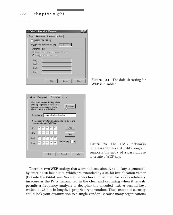
444 c h a p t e r e i g h t
Figure 8.24 The default setting forWEP is disabled.
Figure 8.25 The SMC networkswireless adapter card utility programsupports the entry of a pass phraseto create a WEP key.
There are two WEP settings that warrant discussion. A 64-bit key is generatedby entering 10 hex digits, which are extended by a 24-bit initialization vector(IV) into the 64-bit key. Several papers have noted that this key is relativelyinsecure as the IV is transmitted in the clear and capturing when it repeatspermits a frequency analysis to decipher the encoded text. A second key,which is 128 bits in length, is proprietary to vendors. Thus, extended securitycould lock your organization to a single vendor. Because many organizations

wireless ethernet 445
cannot wait for new security solutions, a bit of common sense and theappropriate location of clients and access points can reduce the risk ofinterception of data. First, enabling WEP makes it harder for interceptions toread your traffic. Second, placing access points and clients so as to minimizeradiation into the parking lot can make it difficult, if not impossible, foran unauthorized person to sit in a van during the day and monitor anorganization’s wireless traffic. Third, if you notice a van in the parking lotwith a directional antenna pointed towards your building you should realizesomething is amiss.


c h a p t e r n i n e
SecurityAs indicated previously in this book, Ethernet primarily represents a layer 2data link protocol used to transport information in a local environment. Assuch, the design of Ethernet is focused upon the lower two layers of theOSI Reference Model. This means that the basic structure of Ethernet is notsecure and an Ethernet network has a variety of vulnerabilities. Thus, it isincumbent upon the higher layers in the protocol stack to provide security toan Ethernet network.
In this chapter we will turn our attention to the general topic of securityand techniques that can be used to protect an Ethernet network. Because webriefly described and discussed wireless LAN security in the form of WiredEquivalency Privacy (WEP) in Chapter 8, our primary focus in this chapter isupon wired Ethernet. However, because wireless Ethernet LANs are commonlyused to provide a connection to a wired infrastructure, our discussion ofsecurity will be applicable to protecting wireless devices accessing a corporatenetwork or the Internet. In this chapter we will first examine the role of therouter, as it represents the first line of defense of a network. This will befollowed by discussing the operation of a firewall and virus scanners.
9.1 The Security Role of the Router
Because a router functions as a gateway between networks, it also representsyour first line of network defense. In this section we will turn our attentionto the security role of this vital communications device. In the first portionof this section we will focus our attention upon router access control. Therationale for this coverage is based upon the fact that most routers areremotely administered. Thus, they can be remotely accessed by persons withevil intentions as well as by authorized employees.
In the second portion of this section we will turn our attention to routeraccess lists, examining how they are created, their use, and limitations.
447

448 c h a p t e r n i n e
Because Cisco Systems has approximately 70 percent of the market for routers,we will primarily describe and discuss access control and access lists withrespect to Cisco routers.
Access Control
Cisco’s Internetworking Operating System (IOS) controls the operation ofthat vendor’s communications devices to include routers and switches. IOSsupport a command line interface that can be accessed via the router consoleport, a modem connection, or a Telnet connection. Of the three methods onlythe first can offer the possibility of being truly secure as it requires a directlyconnected terminal device, which can be co-located with the router in asecure, locked area. Because the other two methods support remote access,they theoretically permit a virtually unlimited number of persons to attemptto access a router’s operating system and represent potential vulnerabilitiesthat you need to consider. However, prior to giving an explanation of thethree methods, a brief discussion of one of the reasons it is relatively simpleto attack a router is in order.
Address and Message Identity
Many organizations employ an IP addressing scheme which results in theassignment of a .1 (dot one) network address to a router’s interface. Thus, ifyou can use ping or nslookup to determine the IP address of a host, it is thenrelatively easy to replace the host address with a ‘‘dot 1’’ address to determineif the device at that address is a router.
A second technique that enables the location of a router is to ping a host forwhich pings onto the host network are blocked. This action results in a routerreturning a ‘‘destination net unreachable’’ message. If the previous methodsdo not yield results, another popular method is to develop a Telnet scanner tosearch for the prompt ‘‘User Access Verification,’’ which is returned by Ciscorouters when you Telnet to a router’s IP address that supports remote access.You can note this by examining Figure 9.1, which indicates an attemptedaccess to a router whose IP address is 205.131.176.1. Note the prompt ‘‘UserAccess Verification.’’
Cisco routers provide you with three tries to enter a password. If you do notenter a correct password the router displays the message ‘‘% bad passwords’’and terminates the Telnet session. This results in the display of the dialog boxshown in the middle of the display that informs the user that the ‘‘connection

security 449
Figure 9.1 Attempting to use Telnet to gain access to a Cisco router.
to host lost.’’ At this time you can manually reconnect and try another seriesof passwords.
Although we did not break into the router in Figure 4.1, we had three triesto do so. If we write a program to continuously try different combinations ofcharacters over a long weekend, it may be possible to gain access to the router.Thus, let’s examine router access in detail.
Cisco EXEC Sessions
Access to a Cisco router results in a command line session that is referred toas an EXEC session. For those familiar with UNIX, an EXEC session is similarto a UNIX shell process.
There are two different types of EXEC sessions supported by Ciscorouters — user EXEC and privileged EXEC. A user EXEC session allowsa person to perform a limited number of functions, such as displayinginterface information, but does not allow the user to change the router’sconfiguration. In a privileged EXEC session you obtain the ability to performrouter configuration operations as well as all of the functions available to theuser EXEC session mode of operation.
All logins to a Cisco router first result in an entry into the router’s user EXECmode. When this occurs you will encounter a greater-than sign (>) prompt.That prompt follows the name configured for the router or, if no name wasassigned, the default ‘‘Router’’ is displayed. To enter the privilege EXEC modea person first enters the command ‘‘enable.’’ This action results in the prompt‘‘Password:’’ which, when a password is successfully entered, places the userin the privileged EXEC mode. When this occurs, the prompt changes to a
450 c h a p t e r n i n e
pound (#) sign — called a hash sign in the UK — as illustrated by the followingsequence for a router named Macon.
Macon > enable
Password:
Macon #
Password Protection
If you have initial access to a Cisco router you can assign a password forinitial access to the router with the password line command. The format ofthis commands is:
Password text
Where ‘‘text’’ can contain any string of alphanumeric characters to includespaces up to 80 characters in length. The alphabetic characters are casesensitive, which provides a router administrator with the ability to createpasswords that would be extremely difficult and time-consuming to guess viaa dictionary or brute-force attack method. Unfortunately, in a haste to configurea router for remote access and to keep things simple, many administrators usesuch classic passwords as ‘‘bingo,’’ ‘‘tiger,’’ ‘‘router,’’ and even ‘‘Cisco.’’
To assign a password for the privileged command level you would usea router’s enable password global configuration command. This means youmust first enter the privileged command level via the enable command. Ifa password for the privileged mode was not previously set, you will notbe prompted for one. Unfortunately, this is a common omission when someorganizations receive their first few routers and rush to establish an Internetconnection. The absence of router passwords can be equated to walkingbarefoot. While you might reach your destination unharmed, there is also adistinct chance of a serious reversal of fortune! Once you enter the privilegedmode, you could use the enable password command as shown below to setthe password to supersecret.
enable-password supersecret
Telnet Access
Each Telnet port on a router is referred to as a virtual terminal (vty). Ciscorouters support a maximum of five vty ports that are numbered 0 through 4.You can configure nonprivileged passwords for Telnet access via the use of

security 451
the password command. The following example illustrates the assignment ofthe password 4hard2guess to vty ports 0 through 4.
line vty 0 4
login
password 4hard2guess
When a user Telnets to the router’s IP address, the router will prompt theuser to enter a password. The user–router interaction will be similar to thatshown below:
%telnet 198.78.46.1
Trying. . . .
Connected to 198.78.46.1
Escape character is ‘∧]’
User Access Verification
Password:
Once the user enters the correct nonprivileged password, the following promptis displayed:
Router>
At this point the remote user can use the enable command in an attempt toaccess the router’s EXEC privileged mode.
Password Encryption
By default anyone who has privileged access to a router can view all ofthe passwords set on the router. For example, suppose you assigned user-names techman and investor the passwords good4me and notgood4u asshown below:
username techman good4me
username investor notgood4u
Without encrypting passwords anyone with privileged access to the router canview each user’s password as well as the general user and enable passwords.This means that it becomes possible for one user to access the router as anotheruser. If you configured your router to log activity to a server, you might be

452 c h a p t e r n i n e
tempted to blame the wrong party for the mess he or she creates, either onpurpose or inadvertently.
Prior to discussing password encryption, a few words about usernamesare in order. The use of the username command allows you to assign sepa-rate, unique, personalized login names for each administrator. By assigningusernames to virtual terminal (vty) liens you can require persons attemptingto gain remote access to a router to know both a username and associatedpassword, which makes it more difficult for an uninvited user to gain accessto a router.
To encrypt router passwords you would use the service password-encryption global configuration command. The format of that command is:
service password-encryption
It should be noted that Cisco’s password encryption scheme produces whatis referred to as a type 7 password because this digit is used as a prefixto the encrypted password scheme. It should also be noted that a searchof the Web using ‘‘type 7 passwords’’ or ‘‘Cisco router password encryp-tion’’ will provide several references to the fact that the encryption schemeused is more accurately a simple scrambling method and that the resultingscrambled passwords can be decoded quite easily. Due to this it is sug-gested that the enable secret command should be used to better protect theenable password.
Using the Enable Secret Command
The use of the enable secret command uses Message Digest 5 (MD5), a one-waycryptographic hash function to encrypt the password. This means that simplere-scrambling will not suffice to obtain the source of the password. Instead,someone must use a password generation program against the algorithm andcompare the result against the MD5 result to determine the clear value of thepassword. This is obviously much more difficult than simply viewing storedpasswords. The following example illustrates the use of the enable secretglobal configuration command:
Macon (config) #enable secret bingo7
Macon (config) #exit
Macon#show running-config
Building configuration. . .
enable secret 5 $e$K3ghM$ 4X. . .
security 453
Note that a prefix of ‘‘5’’ is used to identify the use of MD5. Because ofthis, the resulting encrypted password is also referred to as a type 5 pass-word. You should also note that, because MD5 is a one-way hash algorithm,it cannot be used to encrypt all passwords, such as those used by the Net-work Time Protocol (NTP) and similar protocols that require access to cleartext strings.
You can considerably preclude dictionary and brute-force attacks by select-ing applicable length passwords with an appropriate mix of characters. Byencrypting passwords you make it more difficult for one person to use theaccess privileges of another. While each of these techniques is recommendedto provide a barrier to unauthorized persons gaining access to your orga-nizational routers, you can also limit access via the use of an applicableaccess list.
Access List Restrictions
Although we will discuss the use of Cisco access lists in considerable detailin the second portion of this section, we can note that you can limit access oreven block all Telnet access. To do so you would use several IOS commands.For example, you can use the transport command in conjunction with a linecommand to disable the Telnet listener on your router. The following exampleturns off the Telnet listener on all vty lines:
line vty 0 4
transport input none
You can also use the access-list and access-class commands to limit accessfrom specific IP addresses. For example, assume you want to restrict vty accessto your router to users on the 198.78.46.0 network. To do so you would usethe following IOS statements:
access-list 1 permit 198.78.46.0 0.0.0.255
!
line vty 0 4
access-class 1 in
In this example, the access-list statement permits packets with a sourceaddress on the 198.78.46.0 network. As we will note when we examine accesslists in detail in the second portion of this section, 0.0.0.255 represents a

454 c h a p t e r n i n e
wildcard mask that functions in a reverse manner to a subnet mask, requiringmatches for ‘‘0’’ bit positions and a don’t care for ‘‘1’’ bit positions.
The access-class statement provides you with the capability to define theaccess checks made in a particular direction. The format of this command isshown below:
access-class list number {in|out}where the list number is an integer between 1 and 99 and references thedirection an access list is applied. Because the list number is between 1 and99, this also means that the access-class statement is only applicable to astandard access list. The keyword ‘‘in’’ applies to incoming connections, suchas virtual terminals. In comparison, the keyword ‘‘out’’ applies to outgoingTelnet connections, such as a person who gains access to your router’s EXECmode and attempts to initiate a Telnet connection to another host. Thus,the preceding series of three IOS commands restricts the ability to connect tothe virtual terminals on the router (terminal lines 0 through 4) to hosts on the198.78.46.0 network.
Protecting the Hardwired Connection
Because a connection to the console is accomplished by directly cablinga terminal device to the port, it is assumed that the person operating theterminal is authorized. Due to this, this type of connection is by defaultprovided EXEC mode access without a password. Because it is quite possiblefor an unauthorized person to experiment with gaining full router access, it isa good idea to set a user EXEC password on those ports. To do so you wouldenter the following statements:
line console 0
login
password hard2guess4
exec-timeout 5 0
When you log onto the router its login prompt would be as follows:
User Access Verification
Password:
At this point you would have to enter the password to gain access to therouter. Because the default timeout for an unattended console is 10 minutes,

security 455
you may wish to lower this value. To do so you would use the exec-timeoutcommand whose format is shown below:
exec-timeout m s
where m is the time in minutes and n is the time in seconds of no activitythat forces a session timeout. In the above example we lowered the timeout to5 minutes.
Table 9.1 provides a summary of Cisco security management related com-mands that we previously examined. While the exec-timeout command cantechnically be applicable to supporting a policy to prevent persons fromconnecting and hogging access to the router throughout the day, this authoralso considers the command to enhance security management. Thus, thiscommand is included in the referenced table.
Considering SNMP
The Simple Network Management Protocol (SNMP) represents a potentialvulnerability because it uses community names that are test strings for accesscontrol. All too often the default community name of ‘‘public’’ is used andprovides a mechanism for persons to attempt to exploit an opening in yourrouter’s defense.
TABLE 9.1 Cisco Security Management Commands
Command Operational Effect
line console 0 Establish a password on the console terminal.
line vty 0 4 Establish a password for Telnet connections.
enable-password Establish a password for access to the privilegedEXEC mode.
enable secret Establish an enable secret password using MD5encryption.
exec-timeout m s Establish an idle timeout period in minutes andseconds, which when reached terminates theconnection.
password text Establish a password for access to userEXEC mode.
service password-encryption Scramble the display of passwords to protectthem from view by the use of the showrunning-config command.

456 c h a p t e r n i n e
You can use the snmp-server community command to assign a communityname as well as restrict SNMP operations to read only. The format of thiscommand is shown below:
snmp-server community name {ro|rw} list number
where ‘‘name’’ represents a community name, ‘‘ro’’ represents read only, and‘‘rw’’ represents read/write capability, so certain Management InformationBase (MIB) objects can be changed. ‘‘List number’’ represents an integerbetween 1 and 99 that references a standard access list. Readers are referredto Chapter 10 for detailed information concerning SNMP.
To illustrate an example of the use of the snmp-server community statement,let’s assume you want to restrict access to SNMP reads to one host on the198.78.46.8. To do so you would code the following IOS commands:
snmp-sever community yo4mo52be ro 1
access-list 1 permit host 198.78.46.8
Note that in the first statement we changed the default community nameto you4mo52be. Because you can configure the management station withthe changed community name, you should always use a hard to guessname. In addition, note that we used the ‘‘ro’’ option to restrict access tothe MIB to read-only and used a list number of 1 to associate the firstcommand with the access list that only permits access from the hosts wepreviously defined.
A second SNMP-related area you need to consider is the transmission oftraps. Although most SNMP commands are initiated by a management stationto an agent, an agent can be configured to transmit unsolicited packets tothe management station where certain predefined conditions occur. Theseunsolicited packets represent SNMP traps.
There are three SNMP-related commands you can use to control traps. Thefirst is snmp-server trap-authentication, which enables a router to transmita trap message when it receives a packet with an incorrect communitystring. This is a highly recommended command to use as it will alert themanagement station to mistaken access attempts as well as brute force anddictionary based attacks.
The second command is snmp-server trap-source, which indicates theinterface where traps originate. The third command, snmp-server host, per-mits you to associate an IP address or host name with a community name.For example, assume you want to send traps to the host at 198.78.46.8 from

security 457
interface Ethernet1 using the community name yo4mo52be. You would thencode the following IOS statements:
snmp-server trap-authentication
snmp-server trap-source Ethernet1
snmp-server host 198.78.46.8 yo4mo52be
Now that we have an appreciation of router access control methods includingSNMP, let’s turn our attention to a more formal and detailed examination ofaccess lists.
Access Lists
An access list can be defined as ‘‘an ordered set of statements that permit ordeny the flow of packets across an interface.’’ As such, an access list representsa filtering mechanism since the list parameters are matched against applicableinformation in each packet.
Interface Considerations
The creation of an access list represents the first in a two-part process. Thesecond step is to apply the access list to a specific direction on an interface.Concerning the direction, it is important to note that the flow of packets froma router is considered to represent an outbound direction while the flow ofpackets toward a router represents the inbound direction. This means youmust carefully consider the direction of packet flow in conjunction with thedevices whose packets you wish to filter. To understand this concept better,consider Figure 9.2, which illustrates the direction of inbound and outboundpacket flow with respect to a router that has one serial and two Ethernet ports.
In examining Figure 9.2 note that if you want to block certain types ofpackets arriving from the Internet you would apply an access list to thes0 (serial 0) port in the inbound direction. In comparison, let’s assume youwant to block certain users on the Ethernet1 (e1) network from accessing theInternet. You could apply an access list to either the e1 or s0 interface. If youapply the access list to the e1 interface you would apply it in the inbounddirection. In comparison, if you wanted to use the s0 interface you wouldapply the access list in the outbound direction.
Also note that if you want to block traffic from the 198.78.46.0 networkfrom flowing to the 205.131.175.0 network, you could either filter packetsinbound to interface e1 or outbound from interface e0. In comparison, if you

458 c h a p t e r n i n e
Internet
Router
E1 E0
S0
Server198.78.46.8
205.131.175.0
198.78.46.0
Legend:Outbound packet flowInbound packet flow
Figure 9.2 Inbound and outbound packet flow.
wanted to block traffic on the 198.78.46.0 and 205.131.175.0 networks fromflowing to the Internet, you could apply an appropriate access list to interfaces0. This illustrates an important concept concerning access lists. That is, youmust carefully consider both the interface and the direction an access list isapplied to an interface, topics which we will examine in additional detail aswe expand our coverage of access lists.
Types of Access Lists
Cisco routers support two types of access lists — standard and extended. Inthe first portion of this section we briefly looked at the use of a standardaccess list to control hosts that could gain vty access to a router. Now we willexamine the format and use of access lists in much more detail. In doing so

security 459
we will primarily focus our attention upon IP access lists since IP is the onlyprotocol supported for use on the Internet.
Standard IP Access Lists
The format of a standard IP access list is shown below:
access-list [list #] [permit|deny] [source address] [wild-card-mask] [log]
In examining the format of a standard IP access list a few items require adegree of elaboration. First, the term ‘‘access-list’’ requires a hyphen betweenthe two words. Second, the list number is a numeric between 1 and 99 for theIP protocol and is used to identify the access list statements belonging to acommon access list. Because a standard IP access list number must be withinthe range 1 to 99, the list number also defines the protocol that the access listoperates upon.
Keywords
The permit or deny keyword identifies whether filtering permits or prohibitspackets that match the source address and wildcard mask from flowingthrough an interface. The keyword permit allows packets that match theaddress criteria to flow through an interface, while the keyword deny sendspackets matching the specified source address into the bit bucket.
Source Address
For a standard IP access list the source address represents the IP address ofa host or group of hosts specified using dotted decimal notation. In actuality,the specification of a group of hosts is accomplished through the use of awildcard-mask. Thus, let’s turn our attention to this topic prior to examiningseveral examples of the use of standard IP access list statements.
The Wildcard Mask
As previously noted in this section, the wildcard mask functions in a reversemanner to a subnet mask. That is, this mask uses a binary 0 to represent amatch and a binary 1 to represent a don’t care condition.
To illustrate the use of a wildcard mask, assume your organization hasthe Class C network address of 205.131.175.0. If no subnets were configuredfor that network, each station would have a subnet mask of 255.255.255.0.
460 c h a p t e r n i n e
Here each binary 1 (255 is a byte of all 1’s) represents a match, while a 0 bitrepresents a don’t care condition. Thus, specifying 255 in each of the firstthree positions of the four position subnet mask field results in the TCP/IPprotocol stack matching the network address in each packet and not caringabout the host address. Because the Cisco wildcard mask functions in anopposite manner with respect to binary 1s and 0s, the mask required to allowall packets with a source network address of 205.131.175.0 would be 0.0.0.255.Then, a standard access-list statement that would enable all packets with asource network address of 205.131.175.0 would be coded as follows:
access-list 1 permit 205.131.175.0 0.0.0.255
Because the wildcard-mask represents the complement of the subnet mask,you can determine the subnet mask and take its inverse. For example, a subnetmask of 255.255.0.0 results in a wildcard mask of 0.0.255.255.
As another example of a standard access list, suppose you wish to permitpackets from hosts on the previously mentioned network as well as the198.78.46.0 network but preclude hosts from the 198.78.22.0 network. Youraccess list would be as follows:
access-list 1 permit 205.131.175.0 0.0.0.255
access-list 1 permit 198.78.46.0 0.0.0.255
Wait! Where is the deny statement, you ask? While you could add theappropriate statement, each access list has an implicit ‘‘deny everything’’ atthe end of the list. Because access lists are processed top down, we onlyneed to permit what we want to permit as all else is denied. For those ofus who get tired of typing network addresses and wildcard masks, Ciscoaccess lists support two keywords that can simplify the address specificationprocess. A third keyword provides a logging function. Although most access-list keywords are only applicable to extended access lists, these three are alsoapplicable to standard access lists; so let’s examine them now.
The Host Keyword
Host is used to denote an exact match and represents a shorthand notationfor a mask of 0.0.0.0. For example, assume you want to permit packets fromthe host address 205.131.175.1. To do so you could code the following accesslist statement:
access-list 1 permit 205.131.175.1 0.0.0.0
security 461
Because the keyword host signifies an exact match you can re-code theprevious access list statement as follows:
access-list 1 permit host 205.131.175.1
The Any Keyword
A second keyword supported by a standard access list is any. This keywordis used as an abbreviation for a source address and wildcard mask of 0.0.0.0255.255.255.255. To illustrate the use of host and any keywords, let’s assumeyou want to deny packets from source address 205.131.175.1 and permit allother addresses. The standard access-list statements to accomplish this wouldbe as follows:
access-list 1 deny host 205.131.175.1
access-list 1 permit any
If you observe the order of the two statements, we first explicitly denypackets from the specified host. This is because processing occurs top down.If we reversed the order, the effect would be to permit all packets, a conditionwe would not want to occur in this situation.
The Log Keyword
The keyword log represents an addition to access lists that occurred in IOSVersion 11.3. When you include this keyword in an access list it results in thelogging of packets that match permit and deny statements in the access list.
After you apply an access list with the log keyword to an interface thefirst packet that meets a condition in the list causes an immediate loggingmessage to occur. Thereafter, packets matching the access-list conditions areeither displayed on the console or logged to memory every five minutes.Logged messages include the access-list number, whether the packet waspermitted or denied, the source IP address and the number of packets thatwere matched during the five-minute interval succeeding the first match. Forexample, assume the following standard IP access-list statement:
access-list 1 permit host 205.131.175.1 log
access-list 1 deny host 205.131.175.2 log
Assume that over a five-minute period host 205.131.175.2 issued 10 packets.When the first match occurred, the following would be displayed on the router

462 c h a p t e r n i n e
console or logged to memory, with the actual logging controlled by the ‘‘loggingconsole’’ command:
list 1 deny 205.131.175.2 1 packet
Then, five minutes later the following display or logged message to memorywould occur:
list 1 deny 205.131.175.2 9 packets
The ability to log access-list matches provides you with both a testing andalert capability. You can use logging to test the development of differentaccess lists by observing the resulting match of packets as different activitiesare attempted. When used as an alert facility, you would scan the displayto locate repeated attempts to perform an activity you designed an accesslist to deny. In this situation, repeated attempts to perform an activity theaccess-list statement was developed to deny would more than likely indicatea potential attack.
In examining the standard access-list format, you will note it only providesa mechanism to filter based upon source address. In comparison, an extendedaccess list, as its name implies, extends the packet filtering capability.
Extended IP Access Lists
Through the use of an extended IP access list you obtain the ability to filterbased upon source and destination address, protocol, source and destinationport, as well as other options that significantly enhance your ability to permitor deny packets flowing across an interface. The general format of an extendedIP access list is shown below:
access-list [list#] [permit|deny] [protocol] [source address source-wildcard][source port] [destination address destination-wildcard] [destination port][log] [options]
To obtain an appreciation of the operation of an extended IP access list, let’sexamine the use of each of the fields in the above format to include some ofthe options supported by this statement.
The List Number Field
The list number field identifies statements that make up an access list as wellas the type of access list. An extended IP access list uses numbers 100 through199, which enables 100 unique extended IP access lists to be defined.

security 463
The Protocol Field
The protocol field entry defines the protocol to be filtered. You can filter onIP, TCP, and UDP, as well as on different routing protocols. When creating anextended IP access-list statement, it is important to remember the relationshipof protocols within the TCP/IP protocol suite that form IP datagrams. Thatis, an IP header is used to transport ICMP, TCP, UDP and various routingprotocols. This means that if you specify IP as the protocol to be filtered, allmatches against other fields will cause the packet to be either permitted ordenied regardless of whether the packet represents an application transportedby TCP or UDP, an ICMP message, or a routing protocol. This also means thatif you intend to filter based upon a specific protocol you need to specify thatprotocol. Thus, you need to specify more specific entries prior to less specificentries. For example, assume the following statements:
access-list 101 permit ip any any
access-list 101 deny tcp any host 198.78.46.8
Because the first statement permits IP from any host to any host, this meansyou could not block TCP from any host to the host whose IP address is198.78.46.8 as the second statement would never take effect. You would needto reverse the order of statements, which is why more specific entries shouldbe placed ahead of less specific entries.
Source Address and Wildcard Mask Fields
The source address and wildcard mask for an extended IP access list functionin the same manner as for a standard IP access list. This means that you canuse the keywords ‘‘host’’ and ‘‘any’’ and avoid specifying a mask.
Source Port Number Field
You can use either an integer or a mnemonic to specify a port number. Forexample, to specify the Web’s HyperText Transmission Protocol (HTTP) youcan either use 80 or http. In addition, for TCP and UDP you can use the keywordoperators lt (less than), gt (greater than), eq (equal), and neq (not equal).
Destination Address and Wildcard Mask Fields
The destination address and wildcard mask have the same structure as thesource address and wildcard mask. Thus, you can use the keywords ‘‘host’’

464 c h a p t e r n i n e
and ‘‘any’’ to specify a specific address or any destination address withouthaving to specify a mask.
Destination Port Number
Similar to the source port you can specify the destination port as a numeric ora mnemonic. You can also use an operator to specify a range. The followingexample illustrates the use of both a numeric and a mnemonic to block Websurfing from any source to the 198.78.46.0 network:
access-list 101 deny tcp any 198.78.46.0 0.0.0.255 eq 80
access-list 101 deny tcp any 198.78.46.0 0.0.0.255 eq http
Options
Extended IP access lists support a wide range of options. One commonlyused option is ‘‘log,’’ which was described when we examined standard IPaccess lists. Another commonly used option is ‘‘established.’’ This option isonly applicable to the TCP protocol and is employed to restrict TCP traffic inone direction as a response to sessions initiated in the opposite direction. Toaccomplish this, an access-list statement that contains the word ‘‘established’’results in each packet being examined to determine if its ACK or RST bitis set. If so, this condition indicates that the packet is part of a previouslyestablished TCP connection.
To illustrate the use of the keyword ‘‘established’’ in an extended IP access-list statement, let’s assume that the Ethernet network shown in Figure 9.2has the IP address 205.131.175.0. To restrict TCP packets flowing from theInternet to those in response to packets originating on the Ethernet network,you would use the following access list statement:
access-list 101 permit tcp any 205.131.175.0 0.0.0.255 established
In examining the use of the keyword ‘‘established’’ there are several pointsto note. First, although its use provides a mechanism to control access from arouter’s untrusted side based upon traffic originated from the trusted side, themethod used is rather primitive. That is, packets are considered to be kosher iftheir ACK or RST bit is set, a condition easy for a hacker to overcome. Second,‘‘established’’ is only applicable to TCP as there is no field in a UDP headerto indicate that a UDP Segment is a response packet. As we will note later inthis section, reflexive access lists and Context Based Access Control (CBAC)provide more powerful mechanisms for controlling access via the untrusted

security 465
side of a router, based upon the flow of packets from the trusted side ofthe router.
To facilitate the use of Cisco extended IP access lists, Table 9.2 provides alist of commonly used keywords and a brief description of their use. As wecontinue our examination of the use of IP access lists in this section, we willexamine the use of most of the keywords listed in this table. However, onekeyword deserves a brief mention now as it provides a mechanism to addcomments to an access list. That keyword is remark, which is placed after an
TABLE 9.2 Extended IP Access List Keywords
Keyword Utilization
any An abbreviation for an address and wildcard-maskvalue of 0.0.0.0 255.255.255.255. This keyword isapplicable to both source and destinationaddress fields.
established Causes a match if the ACK or RST bits are set in theTCP header.
host An abbreviation for a wildcard-mask of 0.0.0.0. Thiskeyword is applicable to both source and destinationaddress fields.
icmp-type Provides a mechanism for filtering ICMP messages bytheir message type. You can also specify the ICMPmessage code (0 to 255).
port Provides a mechanism to define the decimal number orname of a TCP or UDP port.
protocol Provides a mechanism to define a specific protocol forfiltering. The specified protocol can include one of thekeywords eigrp, gre, icmp, igmp, igrp, ip, ipinip, nos,ospf, tcp or udp, or an integer between 0 and 255,which represents an IP protocol.
precedence precedence Provides a mechanism for filtering by the precedencelevel name or number (0 to 7) in the IP Type ofService field.
remark Provides a mechanism for adding text comments for anaccess list.
TOS tos Provides a mechanism for filtering based upon thename or service level in the IP Type of Service field.

466 c h a p t e r n i n e
access-list number and allows you to place a comment in an access list. Thefollowing example illustrates its use:
access-list 101 remark allow TCP to our network
access-list 101 permit tcp any any
Rules and Guidelines
There are several general ‘‘rules’’ and guidelines you should consider whencreating and applying Cisco access lists. The rules we will examine representfactual information, while the guidelines represent informative suggestions.The factual information is based upon the manner by which access-listprocessing occurs, while the information suggestions are based upon theexperience of this author.
Top Down Processing The evaluation of an access list results in a sequentialexamination of statements, commencing at the top of the list. This meansyou must carefully consider the order in which you place statements in anaccess list.
Access List Additions New entries are automatically placed at the bottom ofan access list. This means it may be difficult or even impossible to change thefunctionality of an access list. If so, you will then have to consider creating anew list, deleting the existing list, and applying the new list to an interface.
Access List Placement You should consider placing extended access listsas close as possible to the source being filtered. This minimizes the potentialeffect of filtering on the dataflow on other interfaces. In comparison, considerplacing standard access lists as close as possible to the destination. Thisresults from the fact that a standard access list is limited to filtering on sourceaddresses. Thus, if you place the list too close to the source, it could block theflow of packets to other ports.
Statement Placement Because an IP datagram is used to transport ICMP,TCP, UDP, and various routing protocols, you should place more specificentries in an access list before less specific entries. This ensures that theplacement of one statement before another does not negate the effect of astatement appearing later in the list.
Access List Application An access list does not go into effect until it isapplied to an interface via an access-group command. Remember, until the

security 467
access list is applied to an interface, the list has no effect upon the flowof packets.
Filtering Direction Use the filtering direction to define whether inboundor outbound packets are filtered. Remember that packets flowing away froma router’s interface are outbound, while packets flowing towards a routerare inbound.
Router-Generated Packets Packets generated by a router, such as a ‘‘desti-nation net unreachable’’ message or a routing table update, cannot be filteredby an access list applied to outbound traffic. However, you can control suchpackets, either by filtering their arrival via an access list applied in an inbounddirection or by turning their generation off via an applicable IOS command.
Creating and Applying an Access List
Cisco routers support the creation of an access list via several methods. Youcan create an access list directly from the console, via a vty connection, or viaa word processor or text editor. If you use a word processor or text editor youwould store the resulting file as ASCII text and use the computer on whichyou stored the file as a server. To accomplish this you need to install on yourcomputer a trivial file transfer program (TFTP) that operates as a server. Youwould then use the router as a client to upload or retrieve the previouslycreated file. Figure 9.3 illustrates the Cisco TFTP Server screen with its optiondialog box displayed. Note that this is a relatively simple program that allowsyou to specify the TFTP server root directory and the name and location ofa log file, as well as whether or not the progress of file transfers is displayedand logging is enabled.
To apply an access list to a router requires a three-step process. First, youneed to create an access list. Once it is created, you need to apply it to aninterface. Finally, you need a method to define the direction that the accesslist will be applied to an interface.
Specifying an Interface You specify a router interface through the use ofthe ‘‘interface’’ command. For example, to apply an access list to serial port 0(previously shown in Figure 9.2), you would define the interface with thefollowing command:
interface serial 0
Similarly, to apply an access list to a router port connected to a LAN, youwould use the interface command with the name and port identifier of the

468 c h a p t e r n i n e
Figure 9.3 Cisco’s TFTP server program permits you to create access liststhat can be uploaded from a PC by a router.
connection. For example, assuming the router port was e0 shown in Figure 9.2,you could enter the following:
interface ethernet0
Because you can abbreviate most keywords in a command, you could also usee0 in the command as shown below.
interface e0
Using the IP Access-group Command The third step in the three-stepprocess is to define the direction of the interface that the access list workson. To do so you would use the ip access-group command whose format isshown below:
ip access-group [list number] [in|out]
Similar to other commands, the list number identifies a particular accesslist. The keywords ‘‘in’’ and ‘‘out’’ identify the direction that the access listwill be applied. That is, if packets are flowing towards the router you woulduse the keyword ‘‘in,’’ while you would use the keyword ‘‘out’’ if they areflowing out of a particular router interface.
To illustrate an example of the three-step process, let’s create an accesslist. In doing so, let’s assume our network configuration is that shown in

security 469
Figure 9.2. Let’s further assume that we want to restrict data originating fromthe Internet to Web traffic bound for the host whose IP address is 198.78.46.8.In addition, we want to allow users on the 205 and 198 networks shown inFigure 9.2 to initiate Telnet and Web-based queries to hosts on the Internetand allow the results of those queries to return via the Internet. To do so ouraccess list would be as follows:
interface serial0
ip access-group 110 in
access-list 110 remark allow TCP with ACK or RST bit set
access-list 110 permit TCP any any established
access-list 110 remark allow Web access to server
access-list 110 permit TCP any host 198.78.46.8
access-list 110 remark block everything else
access-list 110 deny ip any any
In this example the ‘‘interface’’ command is first used to define serialport 0. Next, the ‘‘ip access-group’’ command is used to apply the access liststatements we will enter as access list number 110 in the inbound direction onthe serial interface. This is followed by the entry of six access list statementsthat form the actual access list. Note that for internal documentation threestatements include remarks. Thus, let’s focus our attention upon the otherthree statements in the access list.
The first non-remark statement permits TCP traffic that responds to queriesinitiated from the internal Ethernet networks. This is due to the keyword‘‘established’’ in the statement. The second non-remark statement permitsWeb traffic (port 80) from any host on the Internet to the server whose IPaddress is 198.78.46.8. The third non-remark statement is not really necessaryas an access list has a ‘‘deny all’’ implicitly placed at the end of the list.
In examining this access list it is important to note that it could create aproblem for Web surfers and other persons using the Internet. This is because,although TCP traffic is permitted, all other traffic is blocked. This means yourinternal network users cannot use DNS as it is carried via UDP, nor can theyuse ping as ICMP messages are not permitted.
To allow UDP we could add the following statement before the‘‘deny’’ statement:
access-list 110 permit UDP any any eq 53

470 c h a p t e r n i n e
In this statement port 53 represents DNS. Thus, instead of opening all UDPaccess we will just allow DNS.
To allow pings we can permit echo replies to echo requests. Thus, we couldadd either of the following statements to our access list:
access-list 110 permit icmp any any echo-reply
or access-list 110 permit icmp any any eq 0
Here the value 0 represents the ICMP type number for echo reply.
Limiting ICMP To make your TCP connection more secure you shouldconsider limiting the types of ICMP messages allowed to flow through yourrouter. As previously indicated in our short extended IP access list exampleaddendum, you can include a permit statement to allow a specific type of ICMPmessage. If you do not allow any ICMP and do not include a permit for the IPprotocol, then all ICMP messages will be blocked. Before you block all ICMPmessages there are certain ICMP messages you should consider permittingand others you may wish to block. Thus, let’s focus our attention upon thosemessages. In doing so we will again assume the access list will be applied tothe serial interface in Figure 9.2 in the inbound direction to the 205.131.175.0network. You will obviously add an additional permit statement if you wishto allow applicable traffic to the other Ethernet network.
Permitting Echo-reply If you have no outbound restrictions, then you areonly filtering an inbound packets. Thus, echo requests transmitted from eitherEthernet result in an echo-reply. To allow responses to those pings you couldcode the following statement into your access list:
access-list 101 permit icmp any 198.78.46.0 0.0.0.255 echo-reply
Permitting Pings Although ping can be used as a discovery weapon to probeyour network to discover information about your organization’s resources, itcan also be helpful for determining the status of certain devices. For example,if your organization administers a remote Web server, you might wish topermit pings to that server from your IP address. Assuming your IP address is192.36.25.11, to permit pings to the server at 198.78.46.8 you would enter thefollowing statement:
access-list 101 permit icmp host 192.36.25.11 host 198.78.46.8 echo
Considering Destination Unreachable By default, when an access list sendsa packet to the great bit bucket in the sky the router will return a type 3 ICMP

security 471
message that has a code value of 13. This message, which is displayed as‘‘Destination net unreachable,’’ informs the person issuing the packet that therouter on the path to that target address is performing access list filtering.There is a special router statement you can use to prevent this informationfrom being determined by a potential hacker. After all, why make their jobeasier? That statement is:
no ip unreachables
which you would enter for each router interface providing an Internet con-nection. The reason you cannot use an access-list statement is due to the factthat router-generated packets are not checked by an access list applied in anoutbound direction. Thus, to turn off the previously mentioned message, youneed to enter the no ip unreachables statement.
Anti-Spoofing Statements
Regardless of the type of access list employed, one of the first series ofstatements in your list should be anti-address spoofing statements. Becausehackers like to use RFC 1918 addresses, you should deny all packets with asource address in three address blocks in RFC 1918. In addition, you shouldblock all packets with an IP address of all zeros, all ones, and the IP loopbackaddress of 127.0.0.0. If your organization does not support multicast (Class D)nor any experimental access via Class E addresses, there is also no reason toallow packets with Class D or class E source addresses. Finally, because somehackers think it is funny to use a source address on the network they areattacking, you should block all packets with a source address associated withyour network. If we assume that the internal network to be protected has thenetwork address 198.78.46.0, then the initial anti-spoofing statements at thebeginning of your access list would be as follows:
!Anti-spoofing statements!!Deny RFC 1918 addresses
access-list 101 deny 10.0.0.0 0.255.255.255 anyaccess-list 101 deny 172.16.0.0 0.31.255.255 anyaccess-list 101 deny 192.168.0.0 0.0.255.255 any
!!Deny address all zeros, all ones, loopback
access-list 101 deny 0.0.0.0 0.255.255.255 anyaccess-list 101 deny host 255.255.255.255 anyaccess-list 101 deny 127.0.0.0 0.0.255.255 any

472 c h a p t e r n i n e
!!Deny Class D and Class E addresses
access-list 101 deny 224.0.0.0 15.255.255.255 anyaccess-list 101 deny 240.0.0.0 7.255.255.255 any
!!Deny source address of your network
access-list 101 deny 198.78.46.0 0.0.0.255 any
Now that we have an appreciation of the operational capabilities of standardand extended IP access lists, let’s turn our attention to new features that wereadded over the past few years that significantly enhance the capability ofrouter packet filtering technology.
New Capabilities in Access Lists
In tandem with several relatively recent updates to the Cisco InternetworkOperating System (IOS) were improvements to the functionality and capabilityof access lists. Six additions to access lists that warrant attention includenamed access lists, dynamic access lists, reflexive access lists, time-basedaccess lists, TCP intercept and Context Based Access Control (CBAC). Inactuality, these additions represent new capabilities added to access lists anddo not literally represent new types of access lists.
Named Access Lists
Because standard and extended access lists have a limited range of acceptablenumbers, it is theoretically possible, although highly unlikely, that you couldrun out of numbers when configuring an enterprise router. Perhaps a moreimportant reason for the use of named access lists is the fact that a name canbe more meaningful than a number. In addition, as we will shortly note, youcan delete statements in a named access list while a numbered list does notprovide this capability.
Overview
Named access lists were introduced in IOS Version 11.2. As its name implies,a named access list is referred to by a name instead of a number.
Standard Named IP Access List
Named access lists are applicable to both standard and extended lists. Theformat of a standard named IP access list is shown below.
ip access-list standard name

security 473
where ‘‘name’’ represents the name you would assign to the standard named IPaccess list. The preceding statement is then followed by one or more permit ordeny statements that define the filtering to take place. The following exampleillustrates the creation of a standard named access list to which we assignedthe name ‘‘inbound’’ to denote that it will be applied in the inbound direction.In this access list we only permit traffic from two defined network addresses:
ip access-list standard inbound
permit 205.131.175.0 0.0.0.255
permit 198.78.46.0 0.0.0.255
To apply a named access list we use a modified version of the previouslydescribed ip access-group command. That modified version includes the nameof a named access list and has the following format:
ip access-group name [in|out]
where ‘‘name’’ represents the name of the named access list. Thus, to apply thepreviously created named access list to the serial0 interface to filter inboundpackets, our IOS statements would appear as follows:
interface serial0
ip access-group inbound in
!
ip access-list standard inbound
permit 205.131.175.0 0.0.0.255
permit 198.78.46.0 0.0.0.255
Now that we have an appreciation for the creation of standard named IP accesslists, let’s turn our attention to extended named IP access lists.
Extended Named IP Access Lists
An extended named IP access list is similar to a standard named IP access list.The format of the extended named IP access list command is shown below:
ip access-list extended <name>
where ‘‘name’’ represents the name assigned to the access list.

474 c h a p t e r n i n e
You can use an extended named IP access list in the same manner as astandard named IP access list. However, because extended access lists provideconsiderably greater filtering capability, you can perform more functions withthis access list. To illustrate an example of the use of an extended named IPaccess list, assume you only want to allow http access to the server shownin Figure 9.2, whose IP address is 198.78.46.8. Let’s further assume you willname the access list ‘‘security.’’ Because you want to filter packets flowingfrom port 31, you would apply the access list in the outbound direction. Basedupon the preceding, the extended named IP access list statements would beas follows:
interface ethernet1
ip access-group security out
!
ip access-list extended security
ip permit tcp any host 198.78.46.8 eq 80
In examining this extended named access list, you may be puzzled as tothe selection of the ethernet1 interface instead of the serial0 interface. Thereason we apply the access list to the ethernet1 interface instead of the serial0interface is that selecting the latter would block all Internet traffic flowinginto the router other than Web traffic flowing to the specified server. Also notethat we specify the direction of the list as being applied to outbound (out)traffic. This is because packets leave the ethernet1 interface to flow to thespecified network.
Editing Capability
We previously mentioned that one advantage of a named access list is thefact you can remove previously entered list statements. To do so you wouldreenter the configuration mode and enter a ‘‘no’’ prefix for the statement youpreviously entered. It should be noted that you cannot delete specific entriesin a numbered access list. One other point that deserves mentioning is the factthat you cannot selectively add statements to any type of access list other thanto the bottom of the list. To add statements to a numbered or a named accesslist you must delete an existing list and reapply a new or modified list withappropriate entries. Now that we have an appreciation for the operation andutilization of named access lists, let’s continue our exploration of additionallist features and turn our attention to dynamic access lists.

security 475
Dynamic Access Lists
As the name of this access list implies, dynamic access lists create dynamicentries in a list. Those dynamic entries represent temporary openings in anaccess list that occur in response to a user authentication process.
Rationale for Use
The primary use of a dynamic access list is to obtain the ability to authenticateusers attempting to access your network. To accomplish this you would first setup user accounts on your router. Next, you would create and apply a dynamicaccess list to the serial port of your router in the inbound direction, assumingyou wish to authenticate users transmitting in that direction. Users then opena Telnet session to your router and authenticate themselves, normally byproviding a user ID and password. Once the user is authenticated, the routerwill close the Telnet session and place a dynamic entry in an access list,which permits packets with a source IP address of the authenticated user’sworkstation.
One of the key advantages associated with the use of a dynamic access listis that it can be used for certain situations where it is not possible to use astatic access list. For example, many Internet Service Providers (ISPs) assigndynamic IP addresses to subscribers. This means that there is no way to createa static access list entry to allow authorized users who have dynamicallyassigned addresses to access your network via an ISP connection other thanto allow all ISP network addresses. Because this would result in a potentiallylarge security gap and is not recommended, you would more than likely turnto the use of a dynamic access list for this situation.
Utilization
The dynamic access list is very similar to an extended IP access list, witha key difference being the inclusion of the keyword ‘‘dynamic’’ in anextended access-list statement. The format of a dynamic access-list entryis shown below:
access-list <list number> dynamic <name> [timeout n] [permit|deny]<protocol> any <destination address> <destination mask>
The first variable field, ‘‘list number,’’ follows the same format as a tradi-tional extended access list and represents a number between 100 and 199. Thesecond variable field, ‘‘name,’’ represents the designated name of the dynamicaccess list. The optional timeout variable can be used to specify an absolute

476 c h a p t e r n i n e
timeout for a particular dynamic entry. The ‘‘protocol’’ parameters representany one of the TCP/IP protocols, such as IP, TCP, UDP, and ICMP. Because thesource IP address is always replaced by the IP address of the authenticatinghost, the keyword ‘‘any’’ should be used for the source IP address field. Thelast two variable fields, ‘‘destination address’’ and ‘‘destination mask’’ areused in the same manner as in an extended IP access list.
Prior to examining an example of the use of a dynamic access list, a fewadditional details warrant discussion. First, you cannot specify more thanone dynamic access-list statement per access list. This means you need toconsider carefully which protocols you want to create dynamic openingsfor in an access list. Second, you need to permit users to Telnet to yourrouter or they will not be able to authenticate themselves and proceed tocreate dynamic openings in the access list. Third, to allow dynamic entriesto be created, you must use the ‘‘autocommand’’ parameter under the vtyline configuration. An example of the use of this command parameter isshown below:
line vty 0 3
login local
autocommand access-enable host timeout 5
In this example the ‘‘host’’ parameter enables the source IP address ofthe authenticating host to be substituted into the dynamic entries thatwill be created. The ‘‘timeout’’ parameter is optional and when includedspecifies an idle timeout. If you use both absolute and idle timers, theidle timer value should be set to a value less than the absolute timer.As a minimum, at least one timer value should be configured. This isbecause without a timer the dynamic entries will remain until the routeris reinitialized.
One additional point deserves mention prior to illustrating the utilizationof a dynamic access list. This point is of key importance because its omissioncan become a network administrator’s nightmare if he or she is remotelyadministrating a router. Because a Telnet session is immediately closed afterauthentication, this action will prevent you from managing a router via Telnet.If you configure your virtual terminal lines as previously described you wouldbe literally up the creek without a paddle. The way around this problemis to specify the ‘‘rotary 1’’ command beneath one or more vty ports as thiscommand enables normal Telnet access to a router on port 3001. For example,to enable normal Telnet access on port 3001 for vty 4, you would enter thefollowing commands:

security 477
line vty 4
login local
rotary 1
Once the preceding occurs, you would set your Telnet application to useport 3001. For example, if your router’s IP address is 205.131.176.1, youwould enter the following command:
telnet 205.131.176.1 3001
Now that we have an appreciation of the details concerning a dynamic accesslist, let’s focus our attention upon an example. In doing so, let’s assume yourrouter is connected to the Internet as shown in Figure 9.4. The serial portof your router has the IP address 205.131.175.1 and you only want to allow
Internet
Router
e0
s0 205.131.175.1
198.78.46.0
Figure 9.4 Configuration to reference for creating a dynamic access list thatpermits authenticated users access to the 198.78.46.0 network.

478 c h a p t e r n i n e
persons with predefined user IDs on the router to access your private network.In addition, we will assume you wish to permit remote administration of therouter via Telnet. To accomplish the preceding you would enter the followingIOS commands. Note that only the relevant portions of the configurationcommands are listed:
username gxheld password gizmo87!interface serial0
ip address 205.131.175.1 255.255.255.0ip access-group 101 in
!access-list 101 permit tcp any host 205.131.175.1 eq 23access-list 101 dynamic gxheld 10 permit ip any 198.78.46.0 0.0.0.255!line vty 0 3
login localautocommand access-enable host timeout 5
line vty 4login localrotary 1
In this example note that we create the user name gxheld and reference itin the second access-list statement. This makes it harder for an attack sincea person must specify both a user name and password to gain access. Alsonote that the first access-list statement restricts access to the router to Telnet(port 23). The second access-list statement contains the keyword ‘‘dynamic.’’This statement creates dynamic openings in the access list, substitutingthe source address of the authenticated Telnet user for all IP traffic witha destination address on the 198.78.46.0 network. Now that we have anunderstanding of the operation and utilization of dynamic access lists, let’sturn our attention to reflexive access lists.
Reflexive Access Lists
When we previously discussed the use of the keyword ‘‘established’’ in anextended IP access list, we noted that it is only applicable to TCP. If you wishto control other upper-layer protocols, such as UDP and ICMP, you would haveto either permit all incoming traffic or define a large number of permissiblesource/destination host/port addresses. In addition to representing a time-consuming and tedious task, the resulting access list could conceivably require

security 479
more memory than available on your router. Perhaps in recognition of thisproblem, Cisco introduced reflexive access lists in IOS Version 11.3.
Overview
A reflexive access list creates a dynamic, temporary opening in an access list,based upon a mirror image of an IP traffic session originated from inside yournetwork to an external network. The temporary opening is always a permitentry and specifies the same protocol as the original outbound packet. Thisopening also swaps source and destination IP addresses and upper-layer portnumbers and remains in existence until either the session initiated on thetrusted network is closed or an idle timeout value is reached.
Rationale for Use
The rationale behind the use of a reflexive access list is to enable employees onthe trusted internal side of the router to control openings in the access list thatoccur from the untrusted side of the network. An example of the operation ofa reflexive access list is shown in Figure 9.5. In examining Figure 9.5 note thatthe inbound opening reverses source and destination IP addresses and portnumbers. Also note that the initial Telnet session uses a destination port of 23and a random source port number greater than 1023. Thus, the opening resultsin a source port value of 23 and a destination port value greater than 1023.
Creation
There are four general tasks associated with the creation of a reflexive accesslist. The first task is to create an extended named access list. In an IPenvironment you would use the following command format:
ip access-list extended name
where ‘‘name’’ represents the name of the access list.The second task is to create one or more permit entries to establish reflected
openings. Because you normally apply a reflexive access list to outboundtraffic, it will result in an inbound access list. When defining permit statementsfor your outbound access list, you use a slightly modified format of the permitstatement. This modified format is shown below:
permit protocol any any reflect name [timeout seconds]
Here the protocol represents the protocol for which you want reflexive open-ings created. Because you normally want any user behind the router to create

480 c h a p t e r n i n e
Internet
Router
e0
s0
User198.78.46.8
Telnet to 205.131.122.6
Opening created from205.131.122.6 to198.78.46.8 from port23 to port 1023
Figure 9.5 Examining the operation of a reflexive access list.
dynamic openings, the keyword ‘‘any’’ is used for the source address. Simi-larly, because reflexive results can represent any swapped addresses and portnumbers, you would also use the keyword ‘‘any’’ for the destination address.The keyword ‘‘reflect’’ identifies the statement as a reflexive statement, while‘‘name’’ represents the name of the access list. The optional keyword ‘‘time-out’’ is used to assign a timeout period to each reflexive entry created inthe inbound direction. If this option is omitted, a default timeout value of300 seconds is used.
You can also place a global timeout value that will be applicable to allreflexive statements. To do so you would use the ip reflexive-list timeoutglobal command, whose format is shown below:
ip reflexive-list timeout value
where ‘‘value’’ represents the global timeout value in seconds.

security 481
The third task associated with the creation of a reflexive access list is tocreate an access list for inbound filtering. This is required as dynamic reflexiveentries will be added to this access list.
The last task in the reflexive list creation process is to conclude your listwith the evaluate command whose format is shown below:
evaluate name
where the variable ‘‘name’’ represents the name of the access list and deter-mines which packets are to be evaluated by reflexive entries.
To illustrate the use of a reflexive access list, let’s assume we want to limitreflected openings to 240 seconds of idle time. Let’s also assume your inboundaccess list will initially be coded to perform anti-spoofing operations bysending RFC 1918 addresses as well as ‘‘all 0’s,’’ loopback and ‘‘all 1’s’’ sourceaddresses to the bit bucket. The following example illustrates the creation ofthe applicable statements for the previously described reflexive access list. Inexamining the statements, note that the six deny statements in the extendedaccess list named ‘‘inbound’’ are conventional statements that are not reflectedbut indicate where reflexive statements will be dynamically added.
ip reflexive-list timeout 240!ip access-list extended outbound
permit tcp any any reflect my-sessionpermit udp any any reflect my-sessionpermit icmp any any reflect my-session
!ip access list extended inbound
deny ip 127.0.0.0 0.255.255.255 anydeny ip host 255.255.255.255 anydeny ip 0.0.0.0 255.255.255.255 anydeny ip host 255.255.255.255 anydeny ip 10.0.0.0 0.255.255.255 anydeny ip 172.16.0.0 0.31.255.255 anydeny ip 192.168.0.0 0.0.255.255 any
evaluate my−session
Limitations
Although the use of reflexive access lists considerably enhances the abil-ity to secure the flow of packets from an untrusted side of a router, theirkey limitation is the fact that they are limited to supporting single-channel

482 c h a p t e r n i n e
connections. This means that applications such as file transfer protocol (ftp)that use multiple port numbers or channels cannot be supported by reflexiveaccess lists. To obtain support for multi-channel applications, Cisco initiallyprovided a special release of IOS referred to as the Firewall Feature Set (FFS),which was limited with respect to the platforms it operated upon. During 1999FFS was incorporated into IOS Release 12.0 under the name Context BasedAccess Control (CBAC). CBAC not only supports multi-channel applicationsbut, in addition, adds a Java blocking capability as well as denial-of-serviceprevention and detection, real-time alerts, and audit trails. Because CBACrepresents the most sophisticated variation of access lists, we will defer anexamination of this access list to the end of this section. Thus, we will con-tinue our examination of access lists by turning our attention to time-basedaccess lists.
Time-Based Access Lists
Until the release of IOS Version 12.0 there was no easy method to establishdifferent security policies based upon the time of day or date. Although youcould create multiple access lists and apply them at different times of theday, doing so could entail a work effort that might be less than desirable.For example, to implement a new security policy to enable Web surfing after6:00 p.m., you would either have to stay in the office until that time or Telnetfrom home and revise your access list. If your organization decides that thepolicy should also revert back to blocking Web surfing at 5:00 a.m., it mightnot be very appealing to get up before your pet to go to work. With theintroduction of IOS Version 12.0 you can now use time-based access lists toobtain the ability to implement different security policies based upon the timeof day.
Creation
The creation of a time-based access list is a relatively straightforward two-step process. First, you define a time range. Once this is accomplished youreference the time range in an access-list entry.
The specification of a time range is accomplished through the use of atime-range statement whose format is shown below:
time-range time-range-name
where the ‘‘time-range-name’’ represents the name you assign to the timerange. Once this task is accomplished you can specify a time range in one of

security 483
two ways. You can use an ‘‘absolute’’ statement or you can use a ‘‘periodic’’statement. The format of each statement is shown below:
absolute [start time date] [end time date]
periodic days-of-the-week hh:mm to [days-of-the-week] hh:mm
The ‘‘time’’ parameter in an absolute statement is entered in the formathh:mm, where hours (hh) are expressed in a 24-hour format. For the periodicstatement you can list the days of the week separated by spaces or use thekeywords ‘‘daily’’ or ‘‘weekend.’’ Once you create a time range, you canreference it through the optional keyword ‘‘time-range’’ in a conventionalaccess-list entry.
Example
Since the old adage ‘‘the proof of the pudding is in the eating’’ holds truetoday, let’s focus our attention upon an example. The following exampleillustrates the creation of a time-based access list that restricts Web access toSaturday and Sunday from 9:00 a.m. until 5:00 p.m.:
time range allow-http
!
periodic weekend 09:00 to 17:00
!
access-list 101 permit tcp any any eq 80 time-range allow-http
TCP Intercept
TCP intercept represents a feature that was added in IOS Version 11.3 as amechanism to minimize the effect of a special type of denial-of-service attackreferred to as SYN flooding and which is also known as a Smurf attack, afterthe cartoon character. With the release of IOS Version 12.0, TCP intercept wasincorporated into Context Based Access Control. Thus, we can literally covertwo topics at the same time by deferring a discussion of TCP intercept andcovering it as we examine context based access control.
Context Based Access Control
Context Based Access Control (CBAC) represents the latest addition to Ciscorouter packet filtering capabilities. Introduced during 1999, CBAC provides a

484 c h a p t e r n i n e
router administrator with the ability to create dynamic entries in a router’saccess list for both single- and multi-channel applications. In addition, CBACprovides the ability to control the flow of Java applets, as well as the ability tominimize the effect of certain types of denial-of-service attacks.
Overview
Until 1999 CBAC was a special feature referred to as the firewall feature set(FFS), which was only available for use on the Cisco series 1600 and 2500router platforms. During 1999 the release of Cisco’s Internetwork OperatingSystem (IOS) Release 12.0T expanded the availability of FFS, which is nowreferred to as CBAC, to Cisco 800, uBR900, 1600, 1700, 2500, 2600, 3600,7100, and 7200 series platforms.
CBAC operates similarly to reflexive access lists, which were previouslycovered in this chapter. As we noted earlier, a reflexive access list is used tocreate dynamic openings in an inbound access list in response to an outbounddata transmission. A key limit of a reflexive access list is its inability to supportmulti-channel applications, such as FTP, CU-SeeMe, H. 323, and similartransmissions that use two or more TCP or UDP ports. CBAC overcomes thislimitation, providing you with the ability to extend the capability of reflexiveaccess lists to multi-channel applications.
Table 9.3 provides a list of representative applications that CBAC cansecurely support. Concerning that support, CBAC functions by examiningpackets that enter or exit a specified interface. Key information contained inthe packet, such as IP addresses and layer 4 port numbers, is placed in a statetable. The contents of that table are then used by CBAC to create temporaryopenings in an access list for returned traffic. Although the operation is similarto that of a reflexive access list, CBAC does this for both single and multi-channel applications. In addition, CBAC tracks the sequence numbers used ina TCP conversation to ensure that they are within the expected range, whichcan prevent a sophisticated attack by someone monitoring a conversation andattempting to piggyback onto it to break into a network resource.
In addition to extending the ability of reflexive access lists, CBAC addsseveral new features that result in much more than an access-list enhancement.These additional features include Java blocking, denial-of-service preventionand detection, and the ability to provide real-time alerts and audit trails.Thus, CBAC can be considered to represent a comprehensive set of securitytools, even though it is enabled in a manner similar to other types of Ciscoaccess lists.

security 485
TABLE 9.3 Examples of ApplicationsSupported by CBAC
Single-channel TCP (i.e., Telnet)
Single-channel UDP (i.e., DNS)
CU-SeeMe (White Pine Software version)
FTP
H. 323 (NetMeeting, ProShare)
IP fragments
Java (applets embedded in HTTP)
Unix r commands (rlogin, rexec, etc.)
RealAudio
RPC (Sun version)
SMTP
SQL*Net
TFTP
Operation
As previously noted, CBAC extends the capability of reflexive access liststo multi-channel applications in addition to adding several new features.Because CBAC monitors outbound traffic to create applicable inbound access-list entries, two access lists are required. One CBAC access list will define thepackets that will be inspected by CBAC. The second access list will includethe entries that CBAC dynamically creates as it compares outbound packetsagainst the statements you will code into an access list that will be applied toa particular interface in the outbound direction.
The actual CBAC configuration process is similar to the manner by whicha reflexive access list is created. That is, you first select an interface and thenconfigure the applicable access lists on the interface. In doing so you use oneor more ‘‘ip inspect’’ statements in the access list you are configuring, whichinforms IOS that it should perform CBAC operations.
CBAC Example
To illustrate the creation of an access list with CBAC capability, let’s assumeyour organization has a branch office with a connection to the Internet as

486 c h a p t e r n i n e
Legend: Workstations
EthernetLAN
EthernetLAN
Router
E0 E1
S0
Internet
Figure 9.6 A sample network to be used for illustrating the configurationand operation of Context-Based Access Control (CBAC).
illustrated in Figure 9.6. In this example we will assume the branch officeoperates two Ethernet LANs, connected to ports #0 and E1 on the router, whileport S0 provides a serial interface to the Internet.
Interface Because the first step in creating any type of access list is to selectan appropriate interface, let’s do so. Assuming we are attempting to protectinternal users on the two Ethernet LANs from the virtually unlimited Internetuser population, we configure CBAC on the external interface, S0. This willresult in any traffic attempting to reach either internal Ethernet networksbeing inspected by CBAC. Now that we have selected an interface, a fewwords about the type and direction of the access lists to be applied to theinterface are in order.
Since we want to protect internal users from traffic flowing inbound fromthe Internet, we create an outbound access list that specifies the traffic to beinspected by CBAC. This access list can be either a standard or extended IPaccess list. As CBAC examines outbound packets it will dynamically createopenings in an inbound access list that governs the flow of traffic from theInternet that can reach either Ethernet network located behind the router. Thisaccess list must be an extended access list.

security 487
One aspect of CBAC that requires elaboration is the fact that it is importantto remember that its use creates dynamic openings in an inbound accesslist based upon the IP address and layer 4 ports used in packets flowingin the outbound direction that match your defined criteria. This meansthat unless you supplement your CBAC-related statements with permissionsfor different types of data originated from the Internet, your organization’sInternet connection will block all inbound traffic originated on the distrustedside of the router. While this may represent your intention, suppose one ofthe Ethernet networks shown in Figure 9.6 is connected to a Web server youwish to allow the general Internet population to access. To do so you mustinclude an applicable permission in the inbound access list to enable trafficto flow through the router to the Web server. Another aspect of CBAC thatwarrants attention is the fact that it does not protect your organization fromcertain types of HTTP application-layer attacks, such as the exploitation ofcgi scripts. Thus, it is important to note that CBAC is not a total barrier tosecurity problems. Instead, it represents a sophisticated tool that adds to thecapability of your organization’s total security policy. That said, let’s turn ourattention to the statements that add CBAC capability to your access list.
The Inspect Statement
The ip inspect statement represents the key IOS command associated withconfiguring a monitored connection for inspection by CBAC. The format ofthis command for all protocols other than Java and RPC (remote procedurecall) is shown below:
ip inspect name inspection-name protocol [alert {on|off}] [audit-trail][on|off ] [timeout seconds]
In this format, the ip inspect command’s optional keyword ‘‘alert’’ causesCBAC to generate messages to a syslog server or the router’s buffer whenever itdetects a violation in the monitored application. For example, if you configureCBAC to monitor TCP and an illegal TCP operation is detected when audit isenabled, the router will send an alert to the syslog server.
The keyword ‘‘audit-trail’’ enables CBAC to track the connections for a pro-tected application. When this keyword is used, the router will log informationfor each permitted application to include source and destination IP addresses,ports used, and the number of bytes transferred. Although the audit trail wasprobably developed to enable network managers to obtain information onthe traffic characteristics of network applications, it also enables managersto determine the locations employees are accessing. Thus, it also provides a

488 c h a p t e r n i n e
database that could be used to determine if employees are viewing the stockmarket, accessing Web auction locations, or performing other activities thatmanagement may not particularly support.
The keyword ‘‘timeout’’ provides you with the ability to specify the durationof inactive sessions. In addition to being able to specify a general inactivetimeout for specific protocols, CBAC also supports the capability to preventdenial-of-service (DOS) attacks by monitoring the number and frequency ofhalf-open connections. For TCP a half-open connection represents a ses-sion that has not completed the initial three-way (syn–syn–ack) handshake.Because UDP has no handshake, a UDP half-open session is one for whichCBAC has not detected return traffic.
You can control the number of TCP and UDP half-open connections throughthe use of ten ip inspect related statements that assign a timeout or thresh-old value. Table 9.4 lists those commands, their default values, and a briefdescription of each statement.
To obtain an appreciation of the entries in Table 9.4, a brief review ofthe operation of denial-of-service (DOS) is warranted. Under a DOS attacka hacker floods a network with either TCP or UDP requests and does notanswer responses to those requests. This action rapidly consumes all availableresources on the target host, which is then forced to deny service to legitimateusers. While using a router to intercept and control DOS attacks ensures thatcomputer resources on the network are available for legitimate use, the routercould easily have its resources consumed. To prevent this situation fromoccurring there are timeout and threshold defaults associated with CBAC asindicated in Table 9.4. You can either elect to accept those defaults and donothing, or modify one or more of those defaults through the use of the ipinspect commands listed in Table 9.4.
To illustrate the use of the basic ip inspect command, let’s assume you wantto create dynamic openings in the inbound direction from the Internet forTCP and UDP applications originating on the trusted side of the router. Let’sfurther assume you want to assign a 60-second timeout for TCP connectionsand a 30-second timeout for UDP connections. To do so you would use thefollowing ip inspect commands:
ip inspect name firewall tcp 60
ip inspect name firewall udp 30
To complete our discussion of ip inspect command formats, let’s turn ourattention to the two previously mentioned variations in the command format

security 489
TABLE 9.4 IP Inspect Commands Used to Configure Time-out and ThresholdValues Used by CBAC
CommandDefaultValue Description
ip inspect tcp synwait-timeseconds TCP
30 s Length of time to wait for session tobe established.
ip inspect tcp finwait-timeseconds
5 s Length of time TCP is managedafter FIN exchange.
ip inspect tcp idle-timeseconds
3600 s TCP idle time-out
ip inspect udp idle-timeseconds
30 s UDP idle time-out
ip inspect dns-timeoutseconds
5 s DNS lookup idle timer
ip inspect max-incompletehigh number
500 sessions Maximum number of half-openconnections permitted beforeCBAC begins closing connections.
ip inspect max-incompletelow number
400 sessions Number of half-open connectionscausing CBAC to stop closingconnections.
ip inspect one-minute highnumber
500 sessions Rate of half-open sessions perminute before CBAC begins closingconnections.
ip inspect one-minute lownumber
400 sessions Rate of half-open sessions perminute causing CBAC to stopdeleting connections.
ip inspect tcpmax-incomplete hostNumber block-timeseconds
50 sessions Number of existing half-opensessions with the same destinationaddress before CBAC beginsclosing sessions.
for RPC and Java. For RPC the format of the command is slightly different asillustrated below:
ip inspect name inspection-name rpc program-number number [wait-timeminutes] [alert {on|off ]] [audit-trail {on|off}] [timeout seconds]

490 c h a p t e r n i n e
As an example of a CBAC inspect statement for RPC, assume you want toallow RPC program number 14000 and effect a 60-second idle timeout. To doso you would use the following inspect command:
ip inspect name firewall rpc program-number 14000 timeout 60
To use CBAC for Java blocking you need to associate a list of permitted IPaddresses via the use of a standard IP access list to a slightly modified inspectcommand. This modified inspect command format is shown below:
ip inspect name inspection-name http[java-list access-list#] [alert{on|off ]][audit-trail {on|off}] [timeout seconds]
In this format the access-list# represents the standard IP access-list numberyou wish to associate with Java blocking. If you should reference an undefinedaccess list in the java-list definition, the default behavior will result in allJava applets being denied since there are no permitted IP addresses associatedwith the ip inspect command.
As an example of the use of CBAC to block Java applets, let’s assume thenetwork address of a parent Ethernet network located on the other side of theInternet in Figure 9.6 is 198.78.46.0. Then, to block all Java applets other thanthose from the parent network, you would code the following commands:
access-list 1 permit 198.78.46.0 0.0.0.255
ip inspect name firewall http java-list 1
Although these commands block all Java applets other than those originatingfrom the 198.78.46.0 network, it should be noted that in its current incarnationCBAC does not block ActiveX. At the present time Cisco recommends the useof a dedicated content-filtering product if you need to perform an extensiveamount of content filtering or if you need to filter one or more applicationsnot presently supported by Cisco access list features to include CBAC.
Applying the Inspection Rules
Similar to other types of access lists, once you create your CBAC inspectionrules you need to apply those rules to an interface. To do so you would usean ip inspect command that indicates the direction of inspection. The formatused to apply an inspection rule is shown below:
ip inspect inspection-name {in|out}

security 491
Note that when applying the inspection you should apply them to thedirection of outbound traffic to ensure that CBAC checks inbound traffic.This means that if you are configuring inspection on an internal interface,the outbound traffic from the network is entering the interface. Thus, inthis situation the inspection rules should be applied inbound. If you areconfiguring inspection on an external router interface, the outbound traffic isleaving the interface. In this situation the inspection rules should be appliedin the outbound direction. While the preceding may appear a bit confusing,you can avoid potential confusion by remembering that you would apply theinspection rule to packets leaving the interface to be guarded to insure thatreturn packets are checked.
Using CBAC
Since the proof of the pudding is in the eating, let’s illustrate the mannerin which we can use CBAC. For our example, let’s assume our organizationhas a two-port router with the serial port providing a connection to anInternet Service Provider, while the Ethernet interface provides a connectionto the internal Ethernet network. Let’s further assume you want to allowthe internal users on your Ethernet LAN to have access to the Internet forWeb browsing, FTP and electronic mail. Let’s also further assume that yourparent organization, whose network address is 205.131.175.0, should be theonly network from which Java applets will be allowed to flow through yourrouter onto your network. In addition, we will assume that you would like touse the alerting capability of CBAC to provide information concerning whenJava applets are blocked or permitted and the auditing capability of CBAC toprovide you with information concerning FTP traffic. Last but not least, youwant to enable your internal Ethernet users to perform ping and tracerouteoperations to hosts on the Internet.
The specific coding we would use to implement the previously statednetwork requirements are listed below:
interface ethernet0ip address 198.78.46.1 255.255.255.0ip access-group 101 in
!!interface serial0
ip address 198.78.40.5 255.255.255.0ip inspect firewall outip access-group 102 in

492 c h a p t e r n i n e
!!ip inspect alert-offip inspect name firewall http java-list 1 alert onip inspect name firewall ftp audit-trail onip inspect name firewall smtpip inspect name firewall tcpip inspect name firewall udp!ip access-list 1 permit 205.131.175.0 0.0.0.255!ip access-list 101 permit ip any any!ip access-list 102 permit icmp any any echo-replyip access-list 102 permit icmp any any time-exceededip access-list 102 permit icmp any any packet-too-bigip access-list 102 permit icmp any any unreachableip access-list 102 permit icmp any any administratively-prohibited
In examining the coding, note that the IOS commands are grouped intoseveral areas. First, we configure the Ethernet interface by assigning an IPaddress to the interface and then associating access list number 101 in theinbound direction with the interface through the use of an ip access-groupstatement. This is followed by the configuration of the serial interface.
Because we will apply CBAC inspection to the serial interface we includean ip inspect command under the serial interface. Note that the ip inspectcommand is set up to inspect packets flowing in the outbound direction as wewant CBAC to create temporary openings in the inbound direction. Becausewe use the ip access-group command under the serial interface, CBAC willcreate temporary openings at the bottom of access list 102 whose statementswe will shortly review.
After the two interfaces have been configured, you will note a block of sixip inspect commands. The first ip inspect command disables global alerting,permitting us to selectively enable this feature for http in the second ipinspect command. Note that the second ip inspect command specifies thatCBAC should use access list number 1 to selectively permit Java applets. Alsonote that after the six ip inspect commands we define a standard access listnumber 1 that only allows traffic from the 205.131.175.0 network. Because thesecond ip inspect statement is linked to access list number 1, this means thatonly Java applets from the 205.131.175.0 network will be permitted inbound

security 493
through our router. Also note that, because we previously mentioned that wewanted to be alerted concerning the permission or blocking of Java applets,the second ip inspect command includes an ‘‘alert on’’ option.
The third ip inspect command configures inspection for ftp, while the fourthcommand provides inspection for sending email. Because we mentioned arequirement to audit ftp, the third ip insert command contains an ‘‘audit-track on’’ option. The fifth and sixth ip inspect commands provide genericTCP and UDP inspection to allow return traffic for queries using differentprotocols from your internal network. For example, by specifying genericTCP permissions, your employees could use call control protocols requiredfor voice over IP (VoIP) session setup. TCP also allows the use of the postoffice protocol (POP), which enables your internal users to retrieve their emailfrom an ISP’s mail server. In comparison, we explicitly specify smtp in an ipinspect command since it is used for sending email and, if we did not specifya generic tcp, our employees would be limited to sending, but not receiving,email. This obviously would not be particularly useful. The use of a genericUDP permits the actual transfer of VoIP packets that applications transferusing the connectionless operation of UDP. In addition, the generic UDPcommand permits employees to use DNS and SNMP as both are transportedas UDP datagrams.
After the block of six ip inspect commands we include two access-liststatements. The first is a standard access-list statement which, as previouslynoted, is linked with our Java applet blocking. The second access list, list 101,permits all IP traffic to flow in the inbound direction to the router from theEthernet network. This access list is not required, but has been included as areference point in the event that we later expand the router and wish to blockcertain types of traffic from the Ethernet network into the router. Because theaccess list permits all IP traffic from any source address to any destinationaddress, its current effect is the same as if we did not associate an access listwith the Ethernet port in the inbound direction.
The last four statements in our router configuration listing consist of fouraccess-list statements. These statements make up an IP extended accesslist numbered 102, which is applied in the inbound direction on the serialinterface. Because CBAC only inspects TCP and UDP traffic, we must explicitlypermit other types of IP traffic through the serial port in the inbound direction.Since part of our previously defined requirement was to permit employees toperform ping and traceroute operations, we need to explicitly enable the IPtraffic required to allow these operations. Thus, we have coded several ICMPpermissions. The permission of echo-reply allows internal users to ping hostson the Internet and receive a reply. The permission of the time-exceeded

494 c h a p t e r n i n e
and unreachable ICMP statements allows traceroute to function. Althoughnot part of our requirement, we have added permissions for packet-too-bigand administratively prohibited ICMP messages. These messages enable MTU(maximum transmission unit) discovery and messages indicating possibleaccess lists on Internet sites our users may attempt to reach. If we had notincluded these ICMP permissions, it is possible that our internal users mightexperience significant delays when attempting to access some locations andmight be prevented from reaching other locations. Because CBAC will ensurethat TCP and UDP entries are automatically created for return traffic, oncetraffic from the internal Ethernet network flows toward the Internet we do nothave to explicitly enable other protocols. Thus, in addition to creating dynamicopenings, CBAC permits us to simplify our access-list creation process.
9.2 The Role of the Firewall
In the first section in this chapter we noted that the router represents theinitial line of defense of an organization’s private network when that networkis connected to the Internet. The key method of defense is the creation ofapplicable access lists that perform packet filtering. While there are severaltypes of access lists and access-list features you can employ by themselves,they are not sufficient to prevent many types of undesirable operationsagainst hosts residing behind a router. One solution to this security gapis to use another communications device that provides additional capabilitybeyond packet filtering. That device is the firewall, which is the focus ofthis section.
Access-List Limitations
Although Cisco routers support many new access-list features, includingdynamic lists that provide an authentication capability and reflexive andcontext-based access control that create dynamic openings in an inboundaccess list based upon outbound activity from the trusted side of a net-work, they all have one serious limitation. That limitation is the fact thatall access lists are relatively blind with respect to the operation being per-formed. This results from the inability of router access lists to look furtherinto the contents of a packet as a mechanism to determine whether or notan apparently harmful operation is occurring, and if so, to either stop theoperation or generate an appropriate alert message to one or more persons inthe form of an audio signal, email message, or pager alert, or a combination ofsuch mechanics.

security 495
Repeated Logon Attempts
Assume you permit employees to use FTP, email, and Web surfing and toperform other Internet activities. Thus, it is possible for a hacker to attempt togain access to your hosts, have some fun, and lock out legitimate users fromaccessing one or more servers. The hacker could also perform a combination ofactivities harmful to the health of your employees’ ability to use organizationalcomputational equipment. For example, by transmitting repeated logins, aperson may be able to either break into a host or lock out a legitimate user.For either situation the hacker repeats a sequence of login actions. Becausean access list does not check the contents of packets, it is possible that therepeated actions continue until a break in occurs or the lock-out value for aparticular valid user ID on a server is reached. One solution to this problemis to examine the contents of each packet and note repeating patterns, whichare then blocked. Because this action requires a considerable amount ofprocessing power, it is normally performed by a firewall. In performing thisfunction the firewall maintains a state table of operations between a particularsource and destination address, with the examination of packets occurring inan attempt to both determine and prohibit certain activities, with the processreferred to as stateful inspection.
Application Harm
A second example of an activity that illustrates a limitation of access lists canbe obtained by discussing certain operations associated with the file transferprotocol (FTP). Although we will focus our attention upon the manner bywhich the FTP application can be hazardous to the health of a remotecomputer, it should be noted that other TCP and UDP applications can attimes also be harmful when used in certain manners.
When using a router’s access list, you can enable or deny ftp sessions basedupon the source IP address and/or the destination IP address contained ineach packet transporting FTP information. Suppose that your organizationoperates an FTP server supporting anonymous access, allowing any personconnected to the Internet to access and retrieve information from the FTPserver, a relatively common occurrence on the Internet. Let’s further assumethat your organization has a large number of files on the server availablefor downloading. This means that a person could either intentionally orunintentionally use the FTP mget (multiple get) command to retrieve a largenumber of files with one ftp command line entry. In fact, if the personaccessing your organization’s ftp server issued the mget command using thewildcard operator of an asterisk (∗) in the filename and file extension position

496 c h a p t e r n i n e
to form the command line entry mget ∗.∗ then this command would resultin your organization’s FTP server downloading every file in the directory,one after another, to the remote user. If your organization has a large numberof files whose aggregate data storage represents several gigabytes of dataand a low-speed connection to the Internet, such as a 56 kbps, 64 kbps orfractional T1 connection, the use of an mget ∗.∗ command could tie upthe outbound use of the Internet connection for many hours and possiblydays. If your organization operates a World Wide Web (WWW) server aswell as an FTP server and provides Internet access to employees over acommon access line, the use of mget on an intentional basis can be consideredto represent an unsophisticated but effective denial-of-service (DOS) attackmethod. This type of attack is perfectly legal as the person employing themget command is performing a perfectly valid operation, even though theresult of the operation could tie up your organization’s connection to theInternet for hours or even days. Similarly, letting a person have the ability todownload data to your organization’s FTP server means they could considerusing the reverse of mget, which is the mput command. Through the use ofmput with wildcards they could set up an antiquated 286 processor-basedmachine and pump gigabytes of data to your FTP server, clogging the inboundportion of your organization’s Internet access line. Recognizing the needto examine application-layer operations and provide organizations with theability to control applications resulted in the development of a proxy servicescapability, which is included in many firewalls.
Proxy Services
Proxy services represents a generic term associated with the use of a proxyserver. The proxy server is normally implemented as a software coding moduleon a firewall and supports one or more applications, for which the server actsas an intermediary or proxy between the requestor and the actual server thatprovides the requested service. When implemented in this manner all requestsfor a specific application are first examined by the proxy service operating onthe proxy server. If the proxy service has previously been configured to enableor disable one or more application features for a specific TCP/IP application,then the proxy service examines the contents of each packet and possiblya sequence of packets and compares the contents against the proxy serviceconfiguration. If the contents of the packet or sequence of packets that denote aspecific operation are permitted by the configuration of the proxy service, thenthe service permits the packet to flow to the appropriate server. Otherwisethe packet is either directly sent to the great bit bucket in the sky or possibly
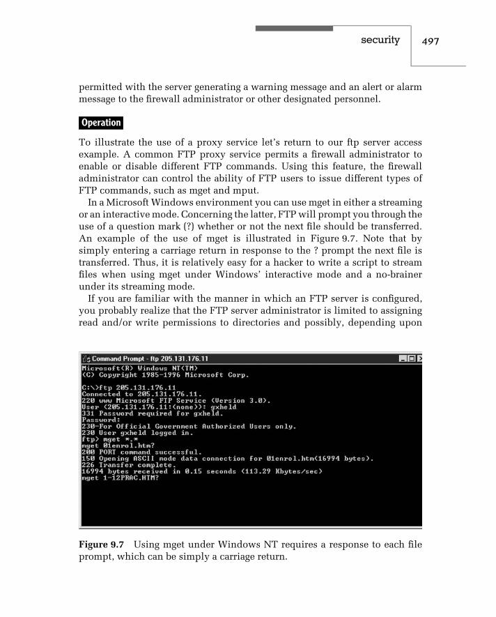
security 497
permitted with the server generating a warning message and an alert or alarmmessage to the firewall administrator or other designated personnel.
Operation
To illustrate the use of a proxy service let’s return to our ftp server accessexample. A common FTP proxy service permits a firewall administrator toenable or disable different FTP commands. Using this feature, the firewalladministrator can control the ability of FTP users to issue different types ofFTP commands, such as mget and mput.
In a Microsoft Windows environment you can use mget in either a streamingor an interactive mode. Concerning the latter, FTP will prompt you through theuse of a question mark (?) whether or not the next file should be transferred.An example of the use of mget is illustrated in Figure 9.7. Note that bysimply entering a carriage return in response to the ? prompt the next file istransferred. Thus, it is relatively easy for a hacker to write a script to streamfiles when using mget under Windows’ interactive mode and a no-brainerunder its streaming mode.
If you are familiar with the manner in which an FTP server is configured,you probably realize that the FTP server administrator is limited to assigningread and/or write permissions to directories and possibly, depending upon
Figure 9.7 Using mget under Windows NT requires a response to each fileprompt, which can be simply a carriage return.

498 c h a p t e r n i n e
the operating system used, to files within a directory for either anonymous ornon-anonymous users, with the latter a term used to denote persons who havean account on the server. However, there is no mechanism that this author isaware of that enables an FTP server administrator or a router administrator toselectively enable or disable individual FTP commands. Thus, an FTP proxyservice provides the FTP server administrator with a significantly enhancedcapability, which can be used to configure the capability and features of ftpservices that other users can access.
Firewall Location
The capability to employ proxy services is based on the use of a firewalllocated between a router and network servers connected to a LAN behindthe router.
To illustrate the common placement of a firewall, as well as a term associatedwith its use, let’s assume we wish to add protection to an Ethernet LANconnected to the Internet. One common method used to protect an internalprivate network from packets flowing from the Internet is to place a firewallbetween the router and the network to be protected. In doing so you wouldinstall an essentially non-populated hub, whose only connections wouldbe to the router and firewall as illustrated in Figure 9.8. Because there areno workstations, servers or any other device except the router and firewallconnections on this hub, it is referred to as a DMZ LAN. Here the term DMZis an acronym for ‘‘demilitarized’’ and originated from a strip of land whereno military activity occurred. If you examine Figure 9.8, you will note thatthis network configuration insures that the flow of packets to and from theInternet has to pass through the firewall before the packets can effect a hostlocated either on the public Internet or on the private network.
The firewall illustrated in Figure 9.8 represents a generic device, the func-tionality of which is highly dependent upon the product selected. Just aboutall firewalls support packet filtering similar to the filtering performed by routeraccess lists as a basic capability. Thereafter, the functionality of firewalls canvary based upon functions and features incorporated into different vendorproducts. These functions and features can include proxy services for dif-ferent applications that allow administrators to control different applicationcommands, limiting the rate of pending connections to counter different typesof denial-of-service attacks. They also provide network address translationto hide internal host addresses from direct attack via the Internet, performauthentication, virus scanning, and even encryption of data, which is a neces-sity when creating a virtual private network (VPN). It should again be noted

security 499
Internet
s0
e0
Router
Non-populatedhub
DMZLAN
Firewall
198 . 78 . 46 . 0 Private network
Figure 9.8 Using a firewall to protect a private network.
that the specific features and functions performed by a firewall considerablyvary between vendor products, a situation we will note when we turn ourattention to two vendor products later in this section.
For organizations that support public access to a Web server, a secondcommon network configuration method is to separate the public and privatenetworks and limit firewall protection to the private network. An example ofthis network configuration is illustrated in Figure 9.9. In this example a publicWeb server is located on the 205.131.175.0 network while the firewall is usedto protect organizational hosts on the 198.78.46.0 network. If the Web server isthe only network device on the 205.131.175.0 network you would more thanlikely create a router access list to limit inbound traffic to the HTTP protocol

500 c h a p t e r n i n e
Internet
Router s0
e1e0
Hub DMZLAN
Publicaccess
Server
205 . 131 . 175 . 0NetworkFirewall
Privatenetwork
198 . 78 . 46 . 0Network
Figure 9.9 Protecting a private network with a firewall while protecting apublic access-list capability.
to the address of the Web server. You should also consider programming TCPintercept to minimize the effect of SYN flooding to the Web server and blockcommonly used spoofed addresses in your access list.
Another popular alternative configuration used with firewalls is to connectboth public- and private-access organizational networks behind the firewall asillustrated in Figure 9.10. In this configuration the firewall is used to protectboth network segments. This action permits you to reduce or eliminate the
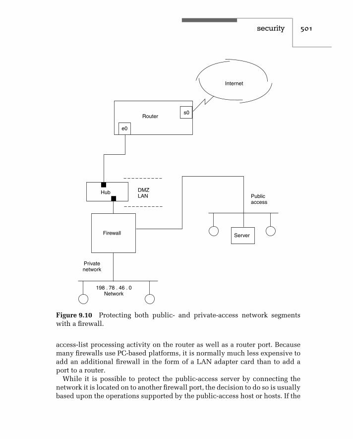
security 501
Internet
Routers0
e0
Hub DMZLAN Public
access
ServerFirewall
Privatenetwork
198 . 78 . 46 . 0Network
Figure 9.10 Protecting both public- and private-access network segmentswith a firewall.
access-list processing activity on the router as well as a router port. Becausemany firewalls use PC-based platforms, it is normally much less expensive toadd an additional firewall in the form of a LAN adapter card than to add aport to a router.
While it is possible to protect the public-access server by connecting thenetwork it is located on to another firewall port, the decision to do so is usuallybased upon the operations supported by the public-access host or hosts. If the

502 c h a p t e r n i n e
server only provides HTTP support, usually protection via a router’s accesslist should be sufficient. If your organization supports public access for HTTP,FTP, Telnet and other applications, you would then probably elect to connectthe public-access network to the firewall as shown in Figure 9.10.
Types of Proxy Services
The type of proxy services that can be provided is only limited by therequirements of an organization and the programming capability of firewallprogrammers. Some of the more popular types of proxy services includeremote terminal Telnet and TN3720 proxy services, Simple Mail TransportProtocol (SMTP) proxy service, HyperText Transport Protocol (HTTP) proxyservice, the previously discussed FTP proxy service and ICMP proxy service.The last represents a special type of proxy service, which deserves a degree ofelaboration due to the enhanced security capability it provides against certaintypes of hacker attacks.
The Internet Control Message Protocol (ICMP) represents a layer 3 protocolwithin the TCP/IP protocol suite. ICMP is used to transmit error messages aswell as status queries and responses to those queries. ICMP packets are formedby the use of an Internet Protocol (IP) header that contains an appropriatenumeric in its Type field, which identifies the packet as an ICMP packet.Although the use of ICMP is primarily oriented towards transporting errormessages between devices operating a TCP/IP protocol stack and is transparentto users of a network, the protocol is also popularly used by many individualswho are probably unaware that they are using transmitting ICMP packets. Thisis because two of the more popular types of ICMP packets are Echo Requestand Echo Reply, which are better known to most persons as a ping operationor application.
The use of ping is primarily designed as a mechanism to allow a user todetermine if a remote host is operational and using a TCP/IP protocol stack.Pinging a distant host with an ICMP Echo Request packet results in the distanthost returning an ICMP Echo Reply packet if the distant host is reachable, if itis operational and if its TCP/IP stack is functioning. While the use of ping canindicate if a distant host is reachable, a ping timeout does not necessarily meanthat the distant host is not operational, because one or more communicationsdevices in the path to the distant host could be down while the distant host isoperational. However, in most cases ping represents the first troubleshootingmethod to use when it appears that a host is not responding to a query.
In addition to indicating that a host is potentially reachable and operational,the use of ping provides information concerning the round-trip delay to

security 503
a remote host. This information results from the ping application on theoriginator setting a clock and noting the time until a response is receivedor a timeout period occurs and no response is received. The time betweenthe transmission of the ping and the receipt of a response represents thepacket round-trip delay and can provide valuable information about whytime-dependent operations, such as Voice over IP (VoIP), produce reproducea voice that sounds like a famous mouse instead of a person.
Although continuous pinging may appear innocent, in actuality it representsa method for a hacker to initiate a denial-of-service attack. This is because thepinged host must stop what it is doing, even if only for a few milliseconds, andrespond to the ping with an Echo Reply ICMP packet. If the person that setsthe ping application to continuous pinging also sets the packet size beyond itsdefault size of 32 or 64 bytes, depending upon implementation, that personforces the destination to respond with responses of increased length, whichrequires the use of additional network resources. Thus, although the use of theping application may not bring the destination host completely to its knees,ping can be configured to operate in a manner that can significantly interferewith the ability of the destination to perform its intended operations.
Another problem associated with the unrestricted use of ping is that it canbe used as a mechanism to discover hosts on a distant network as a preludefor attacking those hosts. For example, a hacker could write a script to cyclethough all 254 possible addresses on a Class C IP network as a mechanism todiscover which addresses are currently operational.
Based upon the preceding, many organizations may wish to control theoperation of ping and other types of ICMP messages. While many router accesslists provide administrators with the ability to filter ICMP packets based uponsource and/or destination IP address and the type of ICMP message, suchaccess-list filtering is an all or nothing operation. That is, a router access listcannot selectively examine and note that a sequence of ICMP Echo Requestsfrom the same source address occurred after a predefined number of requestsflowed through the router and determine that subsequent requests should beprohibited. In comparison, on some firewalls an ICMP proxy service featurecan be configured to differentiate between a single sequence of Echo Requestpackets and the intentional or unintentional setting of a ping application tocontinuously ping a host. Similarly, an ICMP proxy service capability can beemployed to distinguish between a person who may have difficulty accessinga server and another person who is using the ping application in an attempt todiscover all hosts on your organization’s network. Thus, ICMP proxy servicerepresents an important type of proxy service, the use of which can enhancethe security of a network.

504 c h a p t e r n i n e
Limitations
Although proxy services can provide a considerable degree of securityenhancement to networks, there are certain limitations associated with theiruse that warrant discussion. First and foremost, a proxy service requires adetailed examination of the contents of individual and sequences of individ-ual but related packets, forcing the application to look deeper into each packet.This results in an additional degree of processing occurring on each packet,which introduces a degree of delay. Second, a sequence of packets may haveto be examined to determine if it is acceptable to enable those packets to flowto their destination. This means that one or more packets in each sequencemay have to be buffered or temporarily stored until the proxy service candetermine if the packets can proceed to their destination or should be sent tothe great bit bucket in the sky. This also means that additional buffer storagein the proxy server or firewall will be required and the temporary storage ofpackets adds to the latency of remote requests flowing to servers operated byyour organization. In fact, according to tests performed by several communi-cations testing laboratories, as a result of proxy delay, using proxy servicesfrom different vendor firewalls results in between 20 and 40 percent of thebandwidth of an Internet connection at the proxy server side being unusedduring the full utilization on the other side. This also results in a packet lossof between 20 and 40 percent, resulting in additional remote transmissions tothe desired site. Thus, you must consider the effect of proxy service delaysand balance the potential need to upgrade your Internet access line againstthe potential enhancements to the security of your organization’s network.
Operational Examples
Now that we have an appreciation of the capabilities of a proxy firewall,we will turn our attention to an examination of the capabilities of twofirewalls. First, we will examine several configuration screens generated bythe Interceptor firewall, a product of Technologic of Atlanta, GA. Once this isaccomplished, we will turn our attention to FireWall-1, a product of CheckPoint Software Technologies Ltd of Ramat Gan, Israel and Redwood City, CA.
The Technologic Interceptor
Similar to most modern firewalls, the Technologic Interceptor supports itsconfiguration via a Web browser. Figure 9.11 illustrates the Interceptor’sAdvanced Policy Options screen, in which the cursor is shown pointed to thetoggled check associated with the FTP Put command to block FTP uploads. In

security 505
Figure 9.11 Using the Technologic Interceptor firewall configuration screento block all FTP Put commands.
examining Figure 9.11 and subsequent Interceptor screen displays, you willnote they represent HTML screens displayed using a Netscape browser. TheTechnologic Interceptor firewall generates HTML forms to enable networkmanagers to view, add, and modify firewall configuration data. To secure suchoperations the firewall uses encryption and authentication by supporting theSecure Sockets Layer (SSL) protocol for encrypting all traffic between thefirewall and a Web browser used to configure the firewall while passwords areused for authentication. This means network managers can safely configurethe firewall via the World Wide Web.
Using Classes
The Technologic Interceptor firewall includes a class definition facility, whichprovides users with a mechanism to replace address patterns, times of day, orURLs by symbolic names. Classes are initiated by selecting the Classes button

506 c h a p t e r n i n e
on the left portion of the configuration screen. By using an equal sign (=) as aprefix, they are distinguished from literal patterns.
Through the use of classes you can considerably facilitate the configurationof the Technologic Interceptor firewall. For example, suppose you want tocontrol access from users behind the firewall to Internet services. To do so youwould first enter the IP addresses of computers that will be given permissionto access common services you wish them to use. Then you would define aclass name that would be associated with the group of IP addresses and createa policy that defines the services the members of the class are authorizedto use.
Figure 9.12 illustrates the use of the Technologic Interceptor Edit Policyconfiguration screen to enable inbound traffic for FTP, HTTP, Telnet, andSNMP. Note that this policy uses the classname ‘‘= ALL-Internal-Hosts’’ in
Figure 9.12 Using the Technologic Interceptor firewall to create a policyallowing outbound FTP, HTTP, Telnet, and SMTP traffic from all users in thepreviously defined class ‘‘All−Internal-Hosts.’’.

security 507
the box labeled ‘‘From.’’ Although not shown, you would have first used theclass configuration to enter that class name and the IP addresses you wantassociated with that class. Then, this new edit policy would allow those IPaddresses in the predefined class = ALL-Internal-Hosts to use FTP, HTTP,Telnet, and SMTP applications.
Alert Generation
The capability of a firewall is significantly enhanced by an alert generationcapability, enabling a firewall to alert a network manager or administrator to apossible attack on their network. Figure 9.13 illustrates the Technologic Inter-ceptor Add Alert screen display with the IP-Spoof pattern shown selected.
In the example shown in Figure 9.13 the IP Spoof alert is used as a mecha-nism to denote a connection request occurring from a host claiming to have anIP address that does not belong to it. In actuality, it can be very difficult to note
Figure 9.13 Using the Technologic Interceptor firewall Add Alert configura-tion screen.

508 c h a p t e r n i n e
the occurrence of IP spoofing. Although it is relatively easy to consider suchsource IP addresses as those in RFC 1918, all zeros, all ones, loopback andyour network as spoofed IP addresses, others are difficult, if not impossible,to detect. This is because unless the firewall previously obtained informa-tion about IP addresses, such as their locations on segments whose accessis obtained via different firewall ports, or notes restrictions on service by IPaddress, it will assume an IP address is valid. In comparison, other patternssuch as refused connections or failed authentication are much easier to note.For each alert you would first specify a name for the alert definition, suchas IP-Spoof for that pattern. After selecting the pattern, you can specify thedays and times of day and the frequency of occurrence that, when matched,should generate an alert. The Interceptor supports two methods of alert gen-eration — via either email or pager. If you select the use of a pager to transmitan alert you can include a message, such as a numeric alert code, to informthe recipient of the type of alert.
Packet Filtering
In concluding our brief examination of the operation of the Interceptor firewall,we will examine the initiation of packet filtering. Although the packet filteringcapability of firewalls functions in a manner similar to that router feature, thefirewall is usually easier to configure and provides more flexibility in enablingor disabling access based upon the set of rules that can be developed.
Figure 9.14 illustrates the Technologic Interceptor Network Services dis-play, which lists the protocols for which this firewall accepts connections.Note that the HTTP protocol is shown selected as we will edit that ser-vice. Also note the columns labeled ‘‘Max’’ and ‘‘Rate.’’ The column labeled‘‘Max’’ indicates the maximum number of simultaneous connections allowedfor each service, while the column labeled ‘‘Rate’’ indicates the maximumrate of new connections for each service on a per minute basis. By specify-ing entries for one or both columns, you can significantly control access tothe network services you provide as well as balance the loads on heavilyused services.
Figure 9.15 illustrates the Technologic Interceptor Edit Service displayconfiguration screen. In this example, HTTP service is enabled for up to 256connections, and a queue size of 64 was entered, limiting TCP HTTP pendingconnections to that value. The Max Rate entry of 300 represents the maximumrate of new connections that will be allowed to an HTTP service. Once thisrate is exceeded, the firewall will temporarily disable access to that servicefor a period of one minute. If you allow both internal and external access toan internal Web server, the ability to control the maximum rate of incoming

security 509
Figure 9.14 Using the Technologic Interceptor firewall configure screen toedit HTTP network services.
connections to a particular service can be an important weapon in the waragainst so-called denial-of-service attacks. Under this technique, a maliciousperson or group of hackers program one or more computers to issue bogusservice initiation requests using RFC 1918, loopback addresses, or random IPaddresses that more than likely do not exist. Since each access request resultsin a server initiating a handshake response, the response is directed to a bogusaddress that does not respond. The server will typically keep the connectionopen for 60 or 120 seconds, which represents a period of time a valid usermay not be able to access the server when its connection capability is atthe maximum. If you compare this method of limiting HTTP requests to theTCP intercept capability of Cisco routers presented in the first section in thischapter, you will note that the latter represents a better weapon against SYNflooding when compared to earlier versions of Cisco’s IOS. This illustrates animportant concept. That is, there are certain security features that a firewall

510 c h a p t e r n i n e
Figure 9.15 Using the Technologic Interceptor firewall Edit Service configu-ration display to set a series of rules to govern access to HTTP.
provides that may not be available from routers and vice versa. Thus, it isimportant to carefully consider the capabilities of each device.
CheckPoint FireWall-1
FireWall-1 represents a scaleable, modular product from CheckPoint Systemsthat runs on a variety of platforms ranging from Microsoft’s Windows NT toSun’s Solaris, HP-UX and IBM’s AIX version of UMX. FireWall-1 consistsof a troika of components, including a Graphical User Interface client thatoperates on the previously mentioned platforms as well as on Windows 95and Windows 98, a management server onto which security policies createdvia the GUI are saved, and a FireWall module. The last represents softwarethat operates on a device that performs actual packet examination. The devicethat operates the FireWall module is normally considered as a firewall and

security 511
is located at network choke points, where it can examine all packets flowingbetween a public and a private network or another network access location.
The Graphic User Interface
The Graphic User Interface provides the mechanism for defining an organiza-tion’s security policy. To accomplish this, you would first review your networkconfiguration and devise a security policy that corresponds to your organiza-tion’s security requirements and its network configuration. For example, let’sassume your organization plans to place public-access devices, such as mailservers and Web servers, on a separate LAN behind a firewall, while plac-ing your organization’s private network resources onto a separate connectionbehind the firewall. Figure 9.16 illustrates this network configuration. Notethat in this example the public network resources placed on a segment locatedbehind the firewall are referred to as a DMZ.
For the configuration illustrated in Figure 9.16 the security policy that couldbe developed can vary considerably from organization to organization. Onepossible policy for illustrative purposes would be to allow external users to
RouterFirewall
Privatelocal
network
Private networkresources
DMZ LAN
Webserver
Mailserver
Internet
Figure 9.16 Protecting both private and publicly accessible network seg-ments through the use of a firewall.

512 c h a p t e r n i n e
access the local network facilities only to surf the organization’s public Webserver or to send mail. In the outbound direction let’s assume internal userswill be provided with the ability to access all network resources to include theservers on the DMZ LAN as well as the Internet. Note that this policy protectsprivate network resources from the untrusted side of the network representedby the Internet but does not place any restriction on local users on the privatenetwork segment.
Network Objects
Once you have developed a proposed security policy, you would use FireWall-1’s object manager to define one or more network objects that are used by theprogram’s rule base. Network objects can represent any device that has an IPaddress, such as a router interface, a Web server, or the hosts on an internalor external network.
From the Rule Base Editor you can invoke the program’s Network Prop-erties and Router Properties dialog boxes to define various types of networkobjects. Figure 9.17 illustrates the entry of configuration information into thetwo previously mentioned dialog boxes during the network object definitionprocess. The box on the left illustrates the entry of general network properties,including the name assigned to a local network, its IP address, network mask,and applicable comment. Note that, by a simple cursor click, you can definethe location as either internal or external and either permit or deny broadcasts.The right dialog box provides a similar network object definition process fora router.
Figure 9.17 Assigning network object definitions for a local network anda router.

security 513
For our previously described example, the firewall, Web server, mail server,and the private local network would represent network objects to be defined.Once this action has been accomplished, you would define the services to beused to implement your organization’s security policy. In doing so you wouldcreate individual rules that form a rule base.
Firewall-1 Rules
The individual rules supported by Firewall-1 includes seven fields and followsthe format shown in the column headings of Table 9.5. In this format bothsource and destination fields can be set to represent a specific object or anydevice. For example, let’s assume that you previously used the program’sobject manager to assign the label web-server to that server. If you want toprovide any internal or external user with the ability to access the Web server,you would develop a rule with ‘‘any’’ in the source field and ‘‘web-server’’in the destination field. Because the Web server supports HTTP, you wouldconfigure the rule for that service. Concerning the action field, since you wantto allow traffic you would configure that field to ‘‘accept.’’ In comparison, ifyou wish to block packet flow to the Web server the action field would be setto ‘‘drop.’’ The track field can be used to log information or to generate alerts.The field labeled ‘‘Install On’’ denotes the platform upon which the rule beingdeveloped will operate. Finally, the field labeled ‘‘Time’’ provides you withthe ability to control when the rule remains in effect. The first two rules givenin Table 9.5 permit external users to send requests to the Web server and mailto the mail server at any time.
Because we also want to allow users on the internal private network toaccess both the Internet and the organization’s public accessible network, weneed the third rule given in Table 9.5.
Similar to router access lists, FireWall-1 will drop all packets that are notexplicitly permitted by a security policy. Also similar to our discussion ofaccess lists, rules like access-list statements are examined sequentially and
TABLE 9.5 Setting Rules in Firewall-1
Source Destination Service Action Track Install On Time
Any Web-server http Accept Log Gateways Any
Any Mail-server smtp Accept Log Gateways Any
Localnet Any Any Accept Log Gateways Any
Any Any Any Reject Long Log Gateways Any

514 c h a p t e r n i n e
the first rule that matches a connection is applied. Although the implicit ruleat the end of the FireWall-1 rule base is to drop all connections that do notmatch the previous rules, on occasion you may wish to log such connectionattempts. To do so you could enter the final rule in Table 9.5 to terminate yourrule base.
Once you complete the creation of one or more rules necessary to establishyour organization’s security policy, you would load the code generated by therules onto one or more gateways.
One of the more interesting aspects of FireWall-1 is that it can convert yourgeneral rules into a series of access-list statements that can be installed on anyrouter that supports the Open Security Extension (OSE). This means that youcan install your policy on a pure firewall as well as on certain router products.
Figure 9.18 illustrates an example of the use of the CheckPoint Softwarepolicy editor to create a series of six rules. Note that the last rule in effectrepresents an implicit deny all; however, instead of simply sending suchtraffic to the bit bucket, its occurrence will be used to generate alert messages.
Management Functions
Although the previous rule creation example reminds us of access lists, inactuality you can assign a sophisticated series of properties to one or morerules. Properties are assigned through the use of a Properties Setup dialog
Figure 9.18 The CheckPoint Policy editor uses six fields to define rules thatare evaluated top to bottom similar to an access list.

security 515
box and specify both general and specific aspects associated with the flow ofinformation. For example, through the Properties Setup dialog box you candefine the direction by which gateway rules will be applied as well as thelength of TCP session timeouts, encryption, authentication and whether ornot to allow RIP, DNS, and ICMP packets.
Figure 9.19 illustrates the Properties Setup dialog box. At the top of thebox are a series of tabs that enable you to perform the indicated functionslabeled on each tab. In the foreground the Security Policy tab was activated.As you can note from the display, you can use a drop-down menu to selectthe direction of packet filtering as well as a simple click to enable numerousfunctions similar to an applicable router access-list permit statement.
Concerning authentication, the FireWall-1 supports eight authenticationschemes, which range from password to S/Key, SecurID Tokens, RADIUSserver and digital certificates. In addition, FireWall-1 also supports thecreation of virtual private networks by providing a mechanism to encryptcommunications destined for other networks attached to the Internet, whilepassing packets flowing to non-VPN locations in clear. While many of thefunctions performed by this firewall are similar to the capabilities performedby a router’s access list, it is important to note two key differences between thetwo. First, as a stand-alone device a firewall provides more security-related
Figure 9.19 Examining the CheckPoint FireWall-1 Properties Setup dia-log box.

516 c h a p t e r n i n e
functions than commonly available through router access lists. For example,FireWall-1 can provide content checking for HTTP, SNMP and FTP to includeanti-virus checking. Second, by off-loading communications security checkingto a firewall you should obtain a higher level of router performance.
9.3 The Role of the Virus Scanner and Encryption
In concluding this chapter we will become acquainted with a key networksecurity-related area — virus scanning. In this section we will briefly reviewsome of the methods by which malicious code can adversely affect theoperation of a computer. Once this is accomplished, we will describe anddiscuss the use of virus scanners to protect hosts on a network from receivingmalicious code.
Virus Overview
A virus represents a program that reproduces its own code, placing its codein other programs so that, when those programs are executed, the infectionspreads. Although not technically viruses, there are three additional types ofmalicious software that a good virus scanner will check for and which weshould note. Those additional types of malicious software are logic bombs,worms, and Trojan horses.
Logic Bombs
A logic bomb represents a program that lies dormant until it is triggered bya specific event. The trigger can range in scope from a specific date and timeencoded in the software to the receipt of a command to initiate its predefinedoperation. Once activated, the logic bomb will normally perform some typeof insidious operation, such as changing the value of data previously storedon disk, altering the value of a RAM memory location, or attacking a thirdparty. Concerning the latter, the distributed denial-of-service (DDoS) attackemployed against such popular Internet sites as Yahoo and EBay resultedfrom code placed on third-party hosts that were activated by command.
Worms
A work is a program that reproduces itself. Unlike a virus that both adverselyinfects and reproduces, the worm is relatively benign as it does not alteror destroy data. However, each copy of the worm creates additional copies,which can rapidly consume all available computer resources.

security 517
Worms are usually planted on networks and in multi-processing operatingsystems where they can do the most harm. In fact, the well-known ‘‘Internetvirus’’ that brought several thousand computers connected to that network toa halt during the early 1990s was actually a worm.
Trojan Horse
A Trojan horse represents a program that functions as a delivery vehicle fordestructive code that will adversely affect the operation of a computer. Namedafter the Trojan horse that hid soldiers, a Trojan program will appear usefulbut when executed can function as a logic bomb, worm, or virus.
Virus Effect
According to several virus-scanning programs with a built-in database describ-ing different malicious software, there are thousands of identified codes thatperform different types of malicious functions. Thus, it is a bit difficult toattempt to categorize the effect of a virus. However, we can note that theactual effect of a virus can vary from humorous to catastrophic. Some virusesmay simply display the message ‘‘X Shopping Days till Christmas,’’ whileother viruses can alter your hard drive’s boot sector, resulting in the apparentinability to access information previously stored on your hard drive.
One of the most popular methods used by virus developers to replicatetheir code is to name their program as an external command file with theextension .COM when the real command program has the same name but theextension .EXE. The reason for doing so is that the entry of a command nameresults in the operating system executing the file with the extension .COM ifit encounters both .COM and .EXE file extensions with the same file name.A smartly constructed virus using the .COM extension will also execute theactual .EXE command as it spreads its infection. Thus, for a period of timeuntil the cumulative effect of the virus becomes noticeable it will be hiddenbecause the command entered by the user will execute as expected. This typeof virus is referred to as a .COM infection.
Types of Viruses
The types of viruses you can encounter depend upon the ingenuity of thehackers and pranksters who typically develop these programs. Although thetypes of viruses are virtually unlimited, they can be categorized by the mostcommon areas they attempt to infect. These areas are the boot sector and fileallocation table (FAT), system files, and operating system commands.

518 c h a p t e r n i n e
Boot and FAT Infectors
There are two locations that many viruses commonly attack due to the harmtheir alterations can cause. Those locations are the boot sector and the fileallocation table. By changing information in the boot sector, a virus can makeyour hard disk appear to be unusable. By changing data in the FAT, a viruscan make portions of your disk literally ‘‘disappear’’ simply by marking goodsectors as bad or changing a pointer to the next cluster used by a file to anend-of-file cluster value. A few viruses have been known to swap the startingFAT entry address in the root directory, which when performed on a databasefile can result in the subsequent execution of a database processing programusing an output file as an input file and vice versa, a truly insidious trick!
System File Infectors
A system file virus infector changes one of the operating system files. Sincesystem files are always executed upon power-on, their modification functionsas an easy mechanism to replicate a virus. The most popular method todevelop a system file infector is for the virus developer to attach their programcode to a system file. A virus scanner can easily note the occurrence of thistype of file by comparing its size to the size of the legitimate system file. Farmore difficult to detect is the virus that rearranges system file code so it caninsert itself into the file without altering the size of the file. Fortunately, veryfew persons have the knowledge and are willing to devote the time requiredto develop this type of virus. Even if someone does, many virus scanners canbe configured to prevent any executable system file from being sent over acorporate network.
Command Infectors
As previously noted, a command (.COM) infector virus either attaches itselfto an external command file or hides itself by naming itself after an .EXE fileusing the extension .COM. since operating system commands are frequentlyexecuted many times during the day by many computer users, a commandinfector achieves the ability to replicate itself frequently by pretending to bea command. Now that we have a basic knowledge of the types of softwareattacks we can encounter and the manner in which most viruses designed tocause harm operate, let’s focus our attention upon methods we can considerto prevent a software attack and, if unsuccessful in our prevention methods,recover from the effect of an attack.

security 519
Infection Prevention
According to an article published in a recent edition of a national magazine,over 5000 types of worms, logic bombs, and viruses have been identified. Thismeans that it is highly probable that no one prevention and detection strategyor virus scanning program can be expected to represent an absolute guaranteeagainst infection. However, such programs do represent a good starting pointto protect your computer.
Infection prevention software functions as a filter, examining computeroperations susceptible to modification by different types of attack software.Most infection prevention software monitors all I/O operations and disallowsany attempt by code to modify critical disk areas, such as the boot sector,FAT and areas where executable programs that are part of the operatingsystem reside.
Typically, you load the infection prevention software on your hard driveand either modify your AUTOEXEC.BAT file to load the program each timeyou use the computer or place the program for automatic startup underWindows. For either method the infection program functions as a barrier tomost of the commonly used attack software techniques known to result indestructive operations.
Since infection prevention software is designed to detect attack softwareonce it begins to operate, such methods are normally used to locate dormantinfections. To identify previously stored attack software commonly requiresthe use of detection software.
Detection Software
A detection program, now commonly referred to as a virus scanner, searchesyour disk looking for identifying attributes associated with different types ofattach software. Such software may examine the names and size of files todetermine if they are disguised executable files, look for replication code, andsearch system files and the contents of memory looking for any suspiciousalterations.
Virus Scanning
Today both infection prevention and detection of malicious code is commonlyperformed by one program referred to as a virus scanner. To obtain anappreciation of the role of a virus scanner, we will turn our attention to twotypes of products. One type of product operates as a stand-alone program ona desktop, while the second type of program guards the hosts on a networkfrom malicious email, typically by examining inbound email.

520 c h a p t e r n i n e
Desktop Scanning
To illustrate the operation of a desktop virus scanner, this author will useCommand Software System’s Command AntiVirus program. Figure 9.20 illus-trates the main window of this program. Note that this program is installedwith five predefined tasks, which are listed within the window. To illustratethe operation of this program, this author will use it to scan his computer’shard drives. However, note that the program is also capable of scanning net-work drives. In addition, you can also create new tasks by clicking on thebutton with that label. Once you do so you can enter a name for the task anduse a resulting dialog box labeled Properties to specify the type of scanning tobe performed by the task. Later in this section we will examine the dialog boxlabeled Properties and the properties that can be configured for a new task.
General Features
One of the key features of the Command AntiVirus program is its ability toschedule a virus scan as well as send a message when an infection is found.Through the use of the program’s Preferences menu you can send a message.Figure 6.2 illustrates the program’s Network dialog box, which is selectedfrom the Preferences menu. In examining Figure 9.21, note that it providesyou with the ability to display a message when an infection is found as well asto send an email. This program integrates very well with Microsoft’s Outlook,allowing a user to email a report as well as, if desired, the infected filesdiscovered by the scanning process. Thus, you can configure the program toexecute at predefined times and transmit via email any encountered infectionsto a help desk or another central location.
When you use the program dynamically, you can control both the scanningprocess and the action when an infection is noted. To do so you would return
Figure 9.20 The main window of Command Software’s Command AntiVirusprogram includes predefined tasks as well as allows the user to createnew tasks.

security 521
Figure 9.21 The Command AntiVirus program supports a messaging option,which enables other members of an organization to be alerted when a scanindicates the discovery of the infection of a computer.
to the Preferences menu and select the entry labeled Active Protection. Thisaction will result in the display of a dialog box labeled Active Protection,which contains two tabs labeled Dynamic Virus Protection and MemoryScanning. Figure 9.22 illustrate this dialog box with the tab labeled DynamicVirus Protection in the foreground.
In examining Figure 9.22 note that the checkbox next to enable DVP mustbe selected to enable Dynamic Virus Protection. When enabled, the programwill operate in the background and dynamically scan the computer resourcesselected as well as perform the selected action when an infection is encoun-tered. Concerning the latter, note that the right column provides you with fiveoptions concerning the action to be performed in the event an infection isencountered.
Figure 9.22 The Dynamic Virus Protection tab in the Active Protection dialogbox provides users with the ability to specify what computer resources willbe scanned and the action to be performed if an infection is determined.

522 c h a p t e r n i n e
Figure 9.23 The Memory Scanning tab in the Active Protection dialog boxprovides users with the ability to control the scanning of the first 640 kbytesof computer RAM.
The second tab in the Active Protection dialog box is labeled Memory Scan-ning. Figure 9.23 illustrates the tab, which is now located in the foreground ofthe dialog box. Note that the version of the Command AntiVirus program usedby this author was limited to allowing a scan of the first 640 KB of memory.
File Scanning Control
If you are scanning a large-capacity hard drive or many network drives,the scanning process can require a considerable amount of time. Perhapsrecognizing this fact, the Command AntiVirus program provides users withthe ability to specify the types of files to be included or excluded from a scan.To do so you would return to the program’s Preferences menu and select theFiles to Include/Exclude option. Figure 9.24 illustrates the dialog box labeledFiles to Include/Exclude. Note that in addition to predefining file extensionsyou can add new file extensions for inclusion or exclusion in a scan.
The Scanning Process
Since the old adage ‘‘the proof of the pudding is in the eating’’ holds truetoday, this author decided to run a scan. To do so, the task labeled ‘‘ScanHard Drives,’’ previously shown in Figure 9.20, was first selected. The boxin the right portion of the display labeled ‘‘Execute Task’’ was then clickon. Figure 9.25 illustrates the initial execution of the Command AntiVirusprogram at a point in time where 856 files were scanned. As the program

security 523
Figure 9.24 The dialog box labeled Files to Include/Exclude provides userswith the ability to specify files via predefined or entered extensions forinclusion or exclusion in a subsequent scan.
Figure 9.25 Viewing the progress of a virus scan.
scans your hard drive it displays a running progress of the scanning activityas a horizontal bar chart as well as by informing you of the path to the filebeing scanned. Note that at the particular point in time when the screen wascaptured no viruses were found.
Virus Information
One of the more interesting tutorial aspects of the Command AntiVirusprogram is its database of virus information. This database is arranged alpha-betically by virus name, as is illustrated in Figure 9.26. As you select a virus

524 c h a p t e r n i n e
Figure 9.26 Using the Command AntiVirus program to display informationabout a virus.
in the left portion of the screen, the right portion of the screen will displayinformation about the selected virus. This information can be very helpful inallowing one to sleep at night. For example, assume a virus scan performedonce a week located the 3Tunes virus, which you then deleted. You wouldnow more than likely want to know the potential effect of the virus. Althoughyou could more than likely guess its action from the name of the virus in thisexample, this is not always the case. Thus, the ability to view a descriptionof encountered viruses can be an important consideration when selecting avirus scanner in addition to the number of viruses in its scanning databaseand other program features.
Controlling the Virus Scan
In concluding our examination of the Command AntiVirus program we willturn our attention to its Properties dialog box, which represents the key tocontrolling program scans. Figure 9.27 illustrates the Properties dialog boxafter the Scan Hard Drives task was selected.
In examining Figure 9.27 note that you can specify the action to be taken ifan infected file is encountered. You can also specify the drive and paths to bescanned, the types of files to be scanned, and other information, which youcan note by examining the screen. The Properties dialog box also includes abutton labeled Schedule. As you might expect, you can select that button tohave scans automatically performed at predefined times. Now that we havean appreciation of the operation of a typical virus scanning program, let’s turnour attention to the scanning of email.

security 525
Figure 9.27 The Command AntiVirus Properties dialog box provides userswith the ability to control both when and how a virus scan is performed aswell as the actions to occur if infected files are discovered.
Email Scanning
According to several surveys of Internet users, one of the highest rankingreasons for the use of the ‘‘mother of all networks’’ is email. While email iscertainly a key productivity enhancement method for both residential andbusiness oriented persons, it also represents a mechanism for the introductionof viruses. To facilitate the checking of email for attached files that could causeharm you can consider several options. These options include placing a virusscanner on each desktop, precluding inbound email or attachments to email,adding virus scanning capability to your firewall, or installing a separatevirus scanner. The first solution, providing client-based email scanning, canbe relatively expensive to deploy due to the need to install and configuresoftware on each desktop. Precluding inbound email or inbound email withattachments defeats the purpose of providing employees with this productivitytool. Thus, if your organization requires protection from email-based attacks,

526 c h a p t e r n i n e
your realistic choice is between a software module on a router that will scaninbound email or a separate server that operates scanning software.
Protecting the Enterprise
Figure 9.28 illustrates the relationship of an enterprise email scanner serverto other network components. In examining Figure 9.28 note that an emaildestined for any client on the local area network will first flow throughthe router and firewall (1), assuming the datagram(s) transporting the emailand any attachments satisfy any constraints imposed by the router’s accesslist or firewall configuration. The firewall can be configured to functionas a proxy for the Post Office Protocol (POP) server and send the email andattachments directly to the enterprise virus scanner server, where it is scannedand returned (2) to the firewall. The firewall then forwards the email to thePOP server (3). The POP server then forwards the message to the applicableclient (4). Note that as an alternative to the dataflow previously described, it ispossible to direct emails to the virus scanner and the scanner can then directscanned email to the POP server.
2
1
3
4
Client
POPserver Enterprise
virusscannerserver
Router
Firewall
Internet
Figure 9.28 Using an enterprise virus scanner server.
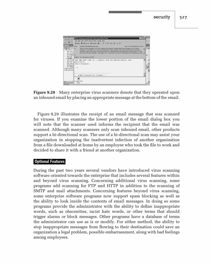
security 527
Figure 9.29 Many enterprise virus scanners denote that they operated uponan inbound email by placing an appropriate message at the bottom of the email.
Figure 9.29 illustrates the receipt of an email message that was scannedfor viruses. If you examine the lower portion of the email dialog box youwill note that the scanner used informs the recipient that the email wasscanned. Although many scanners only scan inbound email, other productssupport a bi-directional scan. The use of a bi-directional scan may assist yourorganization in stopping the inadvertent infection of another organizationfrom a file downloaded at home by an employee who took the file to work anddecided to share it with a friend at another organization.
Optional Features
During the past two years several vendors have introduced virus scanningsoftware oriented towards the enterprise that includes several features withinand beyond virus scanning. Concerning additional virus scanning, someprograms add scanning for FTP and HTTP in addition to the scanning ofSMTP and mail attachments. Concerning features beyond virus scanning,some enterprise software programs now support spam blocking as well asthe ability to look inside the contents of email messages. In doing so someprograms provide the administrator with the ability to define inappropriatewords, such as obscenities, racist hate words, or other terms that shouldtrigger alarms or block messages. Other programs have a database of termsthe administrator can use as is or modify. For either method, the ability tostop inappropriate messages from flowing to their destination could save anorganization a legal problem, possible embarrassment, along with bad feelingsamong employees.

528 c h a p t e r n i n e
Because the best plans and efforts taken to prevent a virus infection could beoverridden by the development of a new strain, it is important to be preparedfor the worst. Thus, in concluding this section, which was focused on viruses,we will describe and discuss the common symptoms of attack software andthe steps you can perform to minimize the effect of an attack.
Recognizing Infection Symptoms
A number of symptoms serve as a warning that your computer is underattack. Some are quite obvious, such as the display of a message that maycontain profanity, attack a politician, or display a similar unexpected andunwarranted message. Other symptoms, such as the activation of a disk drivefor no apparent reason and the illumination of the drive’s light emitting diode,may be much more difficult to note as an indication that your computer isunder attack.
Table 9.6 lists nine of the more common indicators that your computerhas an unexpected visitor. If one or more of these symptoms should occur,there are several actions you should perform and other actions you may wishyou had performed unless you were fortunate enough to prepare yourself torecover from different types of disasters.
Recovery Operations
One of the most important things to understand when you observe an indica-tion that unwanted software is operating on your computer is that whatever
TABLE 9.6 Common Infection Indicators
♦ Programs take longer to load or execute than before.
♦ Disk accesses appear to be excessive for normal tasks.
♦ Disk drives are activated for no apparent reason.
♦ Programs that worked before do not work.
♦ Programs or data files appear to disappear mysteriously.
♦ The use of a utility program shows the presence of mysterious hidden files.
♦ You notice an unexpected reduction in available disk space.
♦ You notice the appearance of an inappropriate message on your screen or strangesounds come from your speaker.
♦ Less memory appears to be available for program execution than normal.

security 529
harm that can happen has already occurred and your actions from this pointonward can prevent further harm from occurring. Unless the unwanted pro-gram has taken control of your computer and is writing continuously to disk,do not power off your computer. If you were not using a virus scanner andhave a program available for use, run it. The chances are high that, if you havea virus or another type of attack program, its techniques may be recognizedand the scanner can locate the program. If a scanner is not available or failsto locate any abnormal software, reboot your system using an original systemdiskette, which loads a good write-protected copy of the operating system,since the original system diskette is permanently write-protected.
Using the newly loaded operating system, attempt to examine the files youused during the operating that resulted in an infection indicator. For example,did you previously execute a command stored as an .EXE file and a directorylisting shows both .COM and .EXE files? If so, the obvious cause of the problemis now apparent. However, what happens if you cannot access your hard driveowing to the modification of your boot sector, FAT, or directory structure?
Although it is probably preferable to have used a disk recover programwhich keeps an image of your key hard-drive sectors on another area of yourdrive to facilitate data recovery, you can also attempt to use an operatingsystem command, such as the DOS command SYS C:, which will rewrite yourDOS boot sector on your hard drive if that area was modified.
If this still does not fix the problem and persons you consult shrug theirshoulders when asked what you should do next, you may be faced withhaving to reformat your drive and reload your software, which was hopefullybacked up on a regular basis. Although this represents a situation most ofus will rarely have to encounter, if you have to reload previously backed-upsoftware it is important to recognize that the cause of your problem may alsohave been placed on your backup tape during your last backup operation.However, since you were able to notice an infection symptom, you also notedan operation you performed which caused the symptom. Thus, after youreload your software, reboot from an original version of the operating systemand attempt to locate and eliminate the cause of your problem.


c h a p t e r t e n
Managing the NetworkWith a little bit of luck, a small network without a significant amount of usagemay require a limited amount of effort by the network manager or administratorto tailor the network to the requirements of the organization. As networksgrow in complexity, the necessity to manage the network increases to the pointwhere network management tools and techniques become indispensable forobtaining an efficiently and effectively run network.
This chapter will focus upon the tools and techniques required to effectivelymanage a network. First, we will examine the Simple Network ManagementProtocol (SNMP) and its Remote Monitoring (RMON) management informa-tion base (MIB). Once this is accomplished, we will focus upon the use ofproducts that can provide us with some of the tools we may require to botheffectively manage the transmission of information on the network, as well asobserve the operation of file servers attached to the network.
Although an Ethernet network is a layer 2 transport facility, it is commonlyused to transport a variety of higher-layer protocols. Thus, any discussionfocused upon the management of Ethernet would be remiss if it did notcover at least one tool you can use to observe the state of higher-layeractivity on an Ethernet network. Recognizing this fact, we will conclude thischapter by examining the use of several software products that can be used toprovide a valuable insight concerning the utilization of an Ethernet networkto include the type of traffic transported and status of different devices onthe network.
10.1 SNMP
The Simple Network Management Protocol (SNMP) was originally developedas a mechanism for managing TCP/IP and Ethernet networks. Since the firstSNMP Internet Draft Standard was published in 1988, the application andutilization of SNMP has considerably expanded, and an enhanced version,
531

532 c h a p t e r t e n
which was originally intended to add several security functions, but dueto conflicts among members of the standardization committee wound uptailoring features in the first version of SNMP, was introduced in 1993. Thatversion of SNMP is referred to as SNMPv2. A third version of SNMP, referredto as SNMPv3, was introduced during 2000 and added such security featuresas authentication and access control. Through the use of SNMP, you canaddress queries and commands to network nodes and devices that will returninformation concerning the performance and status of the network. Thus,SNMP provides a mechanism to isolate problems, as well as analyze networkactivity, which may be useful for observing trends that if unchecked couldresult in network problems.
Basic Components
SNMP is based upon three components — management software, agentsoftware, and management information bases (MIB), the latter representingdatabases for managed devices. Management software operates on a networkmanagement station (NMS) and is responsible for querying agents using SNMPcommands. Agent software represents one or more program modules thatoperate within a managed device, such as a workstation, bridge, router, orgateway. Each managed agent stores data and provides stored informationto the manager upon the latter’s request. The MIB represents a databasethat provides a standard representation of collected data. This database isstructured as a tree and includes groups of objects that can be managed.Concerning the latter, the first MIB, referred to as MIB-I, included 114 objectsorganized into eight groups. Table 10.1 lists the groups supported by thefirst MIB defined by the Internet Standards Organization to include a briefdescription of each group.
In examining the MIB-I groups listed in Table 10.1, it is important tonote that SNMP represents an application layer protocol. That protocol runsover the User Datagram Protocol (UDP), which resides on top of the InternetProtocol (IP) in the TCP/IP protocol stack. Figure 10.1 illustrates the rela-tionship of SNMP protocol elements to Ethernet with respect to the OSIReference Model.
In examining Figure 10.1, note that SNMP represents the mechanism bywhich remote management operations are performed. Those operations aretransported via UDP, which is a connectionless service that can be viewed asproviding a parallel service to the Transmission Control Protocol (TCP), whichalso operates at layer 4 of the ISO Reference Model. At layer 3, the InternetProtocol provides for the delivery of SNMP, controlling fragmentation and

managing the network 533
TABLE 10.1 MIB-I Groups
Group Description
System Provides vendor identification to includeconfiguration in information and time since themanagement portion of the system was lastreinitialized.
Interfaces Provides single or multiple network interfacesthat can be local or remote, and designates theoperating rate of each interface.
AddressTranslation Table Provides a translation between the networkaddress and physical address equivalences.
Internet Control MessageProtocol (ICMP)
Provides a count of ICMP messages and errors.
Transmission ControlProtocol (TCP)
Provides information concerning TCPconnections, transmissions, and retransmissionsto include maintaining a list of activeconnections.
User Datagram Protocol(UDP)
Provides a count of UDP datagrams transmitted,received, or undelivered.
Exterior GatewayProtocol (EGP)
Provides a count of interrouter communications,such as EGP locally generated messages, EGPmessages received with and without error, andinformation on EGP neighbors.
reassembly of datagrams, the latter a term used to reference portions of amessage. Located between IP and layer 4 is the Internet Control MessageProtocol (ICMP). ICMP is responsible for communicating control messagesand error reports between TCP, UDP, and IP.
In addition to being transported via UDP, SNMP can be transported viaNovell’s IPX, within Ethernet frames and through the use of AppleTalk andOSI transports. In 1992, a new MIB, referred to as MIB-II, became an Internetstandard. MIB-II included the eight groups of MIB-I previously listed inTable 10.1, as well as two new groups — Common Management Informationand Services Over TCP (CMOT) and SNMP. When the effort to run ISO’smanagement on top of TCP/IP was abandoned, CMOT was essentially droppedas an active group. The addition of an SNMP group permits SNMP to trackeverything to include its own traffic and errors.

534 c h a p t e r t e n
Application
Presentation
Session
Transport
Network
Data link
Physical
SNMP
User DatagramProtocol (UDP)
ICMP
InternetProtocol (IP)
Ethernet
Physical
7
6
5
4
3
2
1 Figure 10.1 Relationship of SNMPprotocol elements to Ethernet.
Operation
SNMP has a core set of five commands referred to as protocol data units (PDUs).Those PDUs include GetRequest, GetNextRequest, SetRequest, GetResponse,and Trap.
The Network Management Station (NMS) issues a GetRequest to retrievea single value from an agent’s MIB, while a GetNextRequest is used to walkthrough the agent’s MIB table. When an agent responds to either request, itdoes so with a GetResponse.
The SetRequest provides a manager with the ability to alter an agent’sMIB. Under SNMP Version 1, there was no method to restrict the use of thiscommand, which if used improperly could corrupt configuration parametersand impair network services. Recognizing this problem, many vendors electednot to support the SetRequest command in their SNMP agent software. Theintroduction of SNMP Version 3 added authentication as well as encryption,resulting in a network management message received by an agent to berecognized if it was altered, as well as to be verified that it was issued by theappropriate manager. This permits the SetRequest to be supported withoutfear of an unauthorized person taking control of a portion of a network, or anagent returning false information.
Since SNMP is a polling protocol, a mechanism was required to alertmanagers to a situation that requires their attention. Otherwise, a long polling

managing the network 535
interval could result in the occurrence of a serious problem that might goundetected for a relatively long period of time on a large network. Themechanism used to alert a manager is a Trap command, issued by an agent toa manager.
Under SNMP Version 2, two additional PDUs were added — GetBulkRequestand InformRequest. The GetBulkRequest command supports the retrieval ofmultiple rows of data from an agent’s MIB with one request. The InformRequestPDU enables one manager to transmit unsolicited information to anothermanager, permitting the support of distributed network management, whichuntil SNMP V2, was performed in a proprietary manner.
One of the problems associated with the development of MIBs was theprovision within the standard that enables vendors to extend their database ofcollected information. Although the tree structure of the MIB enables softwareto be developed by one vendor to read another vendor’s extension, doingso requires some effort and on occasion results in interoperability problems.To reduce a degree of interoperability, the Remote Monitoring (RMON) MIBwas developed as a standard for remote-LAN monitoring. RMON provides theinfrastructure that enables products from different vendors to communicatewith a common manager, permitting a single console to support a mixedvendor network.
10.2 Remote Monitoring
Remote Monitoring (RMON) represents a logical evolution of the use of SNMP.RMON provides information required for managing network segments that canbe located in your building or on the other side of the world.
Operation
RMON operations are based upon software or firmware operating either inmanaged devices or managed stand-alone hardware probes. Managed devicescan include such programmable hardware products as bridges, routers, gate-ways, hubs, workstations, minicomputers, and mainframes that are connectedto a network. Through appropriate software, each managed device respondsto network management station (NMS) requests transported via the SNMPprotocol. Although a stand-alone probe can be considered to represent amanaged device, it differs slightly from the previously mentioned devices inthat it is firmware-based and is restricted to performing one set of predefinedtasks — RMON operations.

536 c h a p t e r t e n
Whether an RMON agent is a managed device or managed stand-alone probe,it captures predefined data elements and will either send statistics and alarmsto a network management station upon request for statistics, or generate a trapcommand upon occurrence of a preset threshold being exceeded, resulting inthe generation of an alarm condition that the NMS will then pool.
Figure 10.2 illustrates the relationship between a network managementstation and a series of managed devices consisting of RMON agents or probes.The MIB provides a standard representation of collected data, as well asdefines groups of objects that can be managed. At the NMS, one or moreapplication programs control the interaction between the NMS and eachmanaged device, as well as the display of information on the NMS andgeneration of reports. Other functions performed by NMS applications caninclude password protection to log on to and take control of the NMS,support for multiple operators at different locations, forwarding of criticalevent information via e-mail or beeper to facilitate unattended operations,and similar functions.
The RMON MIB
Remote network monitoring devices or probes represent hardware andsoftware designed to provide network managers and administrators withinformation about different network segments to which they are attached.The remote networking monitoring MIB was originally defined in RFC 1271,which was obsoleted by RFC 1757, issued in 1995. Under both RFCs the MIBconsists of objects arranged into nine groups.
RMONagent
MIB
RMONagent
MIB
RMONagent
MIB
Network Management Station(NMS)
SNMPprotocol
Manageddevice
Manageddevice
Manageddevice
Figure 10.2 RMON operation.

managing the network 537
The key difference between RFCs is the size of the counters, which wereexpanded from 32 to 64 bits under RFC 1757. This expansion was in recog-nition of the fact that, as users installed faster Ethernet networks, counterswould reach their maximum value in a shorter period of time. Table 10.2 listseach MIB group and provides a brief description of the function of each group.All groups in the MIB listed in Table 10.2 are optional and may or may not besupported by a managed device.
Both the statistics and history groups can provide valuable informationconcerning the state of the Ethernet segment being monitored. The statisticsgroup contains 17 entries for which countervalues are maintained, while thehistory group contains 11 entries for which countervalues are maintained. In
TABLE 10.2 Remote Network Monitoring MIB Groups
Group Description
Statistics Contains statistics measured by the RMON probe foreach monitored interface.
History Records statistical samples from a network for aselected time interval and stores them for laterretrieval.
Alarm Retrieves statistical samples on a periodic basis fromvariables stored in a managed device, and comparestheir values to predefined thresholds. If the monitoredvariable exceeds a threshold, an alarm event isgenerated.
Host Contains statistics associated with each hostdiscovered on a network.
HostTopN A group used to prepare reports that describe the hoststhat had the largest traffic or error counts over aninterval of time.
Matrix Stores statistics of traffic and errors between sets oftwo addresses.
Filter Permits packets to be matched based upon a filterequation.
Packet Capture Permits packets to be captured after they flow througha channel.
Event Controls the generation and notification of events fromthe managed device.

538 c h a p t e r t e n
addition, the history group includes the real-time maintenance of an integervalue that denotes the mean physical layer network utilization in hundredthsof a percent.
Table 10.3 provides a comparison of the measurements performed by thestatistics and history RMON groups. Although both groups provide essentiallythe same information, there are some significant differences between the two.The first major difference is the fact that the statistics from the statistics grouptake the form of free-running counters that start from zero when a valid entryis received, and provide information concerning the recent operational stateof the segment. In comparison, the statistics in the history group provide
TABLE 10.3 Comparing Statistics and History GroupMeasurements
Statistics History
Drop Events Yes Yes
Octets Yes No
Packets Yes Yes
Broadcast Packets Yes Yes
Multicast Packets Yes Yes
CRC Alignment Errors Yes Yes
Undersize Packets Yes Yes
Oversize Packets Yes Yes
Fragments Yes Yes
Jabbers Yes Yes
Collisions Yes Yes
Packets 64 octets in length Yes No
Packets 65–127 octets in length Yes No
Packets 128–255 octets in length Yes No
Packets 256–511 octets in length Yes No
Packets 512–1025 octets in length Yes No
Packets 1024–1518 octets in length Yes No
Utilization No Yes

managing the network 539
information more useful for long-term segment trend analysis. Recognizingthese differences, the statistics group tracks different packet lengths, while thehistory group ignores packet lengths and tracks network utilization.
Since a managed device or probe is essentially useless if a segment becomesisolated from the organizational network due to a router or bridge failureor cabling problem, some vendors provide Ethernet RMON probes withredundant access capability. This capability is normally provided through theuse of a built-in backup modem or ISDN support. Another common featureoffered with some stand-alone probes is a multisegment support capability.This feature enables a single probe to be used to provide support for up to fournetwork segments, assuming cabling distances permit. Figure 10.3 illustratesthe use of a multisegment RMON probe to capture and report statistics for twoEthernet segments at one location to an NMS at a remote location.
Managing Remote Networks
To illustrate the use of a network management platform to remotely mon-itor two Ethernet LANs, this author used Network General’s Foundation
R
R
NMS
Multisegmentprobe
Legend:
NMS = Network management stationR = Router
Figure 10.3 Using a multisegment RMON probe.

540 c h a p t e r t e n
Manager program. It should be noted that Network General was one of severalcompanies that were acquired by Network Associates during the past fewyears. Figure 10.4 illustrates the selection of this program’s Remote Quick-Stats bar, which enables you to specify an IP address of a probe on the remotenetwork you wish to monitor. Once this is accomplished, the program willuse that address to access the probe and retrieve predefined MIB elementssuch as the distribution of packet lengths shown in the upper left portion ofFigure 10.4. In fact, if you compare the last seven entries in Table 10.3 withthe contents of Figure 10.4, you will note that the packet distribution shownin Figure 10.4 and the usage meters in that illustration correspond to thoseseven statistics entries in the table.
One of the key features of Foundation Manager is its ability to provideusers with the capability to remotely monitor up to eight networks at onetime and simply click on an icon to change the display of statistics from onemonitored network to another. This capability is shown in Figure 10.5 wherethe first two of eight QuickStat buttons are darkened to indicate two remote
Figure 10.4 Using Network General’s Foundation Manager QuickStats fea-ture enables you to view key statistics concerning the operational state of aremote network.

managing the network 541
Figure 10.5 Through the use of up to eight QuickStat buttons, FoundationManager can be used to monitor up to eight remote networks.
LANs are being monitored. Here the second QuickStat button is associatedwith an Ethernet LAN in San Antonio, and clicking on the first button wouldimmediately bring up the statistics screen for Sacramento that was previouslyshown in Figure 10.4.
In examining the screens shown in Figures 10.4 and 10.5, you will noteboth provide the same key metrics for each monitored network. Those metricsinclude the distribution of packets, network usage, traffic in terms of frames,and bytes and broadcasts. In addition, the lower portion of each screenprovides a graph over time of the percentage of network utilization andbroadcast traffic. Thus, at a glance you can visually note the current use ofthe monitored network and whether or not a metric indicates a potential orexisting problem that requires closer examination.
10.3 Other Network Management Functions
Now that we have an appreciation for SNMP and RMON, we can turn ourattention to a detailed discussion of a core set of network management

542 c h a p t e r t e n
functions you can use as a mechanism to evaluate the suitability of differentvendor products. As we will shortly note, upon occasion no one product willsatisfy all of your management requirements and you may have to turn tomultiple products to view network operations. Thus, we will conclude thischapter by examining the use of several network management tools you canuse to observe network performance.
There is a core set of five functions associated with network manage-ment. Those functions are configuration, performance, fault, accounting, andsecurity management. Each functional area manages a set of activities.
Figure 10.6 illustrates the functional areas commonly associated with net-work management and the set of activities managed by each area.
Configuration Management
The process of configuration management covers both the hardware and soft-ware settings required to provide an efficient and effective data transportationhighway. Thus, configuration management consists of managing the physicalhardware — including cables, computers, and network adapters — along withthe logical network configuration governed by the installation of the networkoperating system, the selection of a network protocol or stack of protocols,and the manner in which users can access server facilities. The latter concernsthe setup of the network, including permissions and routings that enableusers to access different servers. Although this may appear to involve securitymanagement, it is mainly focused on the setting and distribution of network
Networkmanagement
Configurationmanagement
Performancemanagement
Faultmanagement
Accountingmanagement
Securitymanagement
PhysicalconfigurationLogicalconfiguration
Networkactivitymonitoring
Problemdetection
Data usagecollectionComputationReportgeneration
PhysicalsecurityLogicalsecurity
ProblemisolationProblemresolution
Resource useexaminationBandwidthcapacitydetermination
Figure 10.6 Network management functional areas.

managing the network 543
passwords and the assignment of file permissions. Thus, logical configurationmanagement permits a user to reach a network facility once he or she isconnected to the network, while security management involves the ability ofa user to gain access to the network and to different facilities made availableby configuration management.
Performance Management
Performance management involves those activities required to ensure that thenetwork operates in an orderly manner without unreasonable service delays.This functional area is concerned with the monitoring of network activity toensure there are no bottlenecks to adversely affect network performance.
Monitored network activity can include the flow of data between stationsand between stations and servers; the use of bridges, routers, and gateways;and the utilization of each network segment with respect to its total capacity.By performing these tasks, you will obtain information that will enable youto adjust the use of network hardware and software, as well as to consider avariety of network segmentation options that can eliminate potential networkbottlenecks before they occur.
Fault Management
Networks have their less desirable moments in which components fail,software is configured incorrectly, and other problems occur. Fault man-agement is the set of functions required to detect, isolate, and correctnetwork problems.
A large number of hardware and software products are now marketed toprovide a fault management capability for cables, hardware, and networksoftware. The most common type of diagnostic device is a time domainreflectometer, which generates a pulse and uses its reflected time delay (orabsence of a reflection) to isolate cable shorts and opens. LAN protocolanalyzers allow you to test individual Ethernet adapters, and to monitornetwork performance and isolate certain types of network problems, such asjabbering. Both hardware-based LAN protocol analyzers and many softwareproducts provide a LAN frame decoding capability. This helps you determinewhether the flow of frames and frame responses provides an insight intonetwork problems. For instance, a station might be rejecting frames becauseof a lack of buffer space, which could easily be corrected by reconfiguringits software.

544 c h a p t e r t e n
Accounting Management
Accounting management is a set of activities that enables you to determinenetwork usage, generate usage reports, and assign costs to individuals orgroups of users by organization or by department. Normally, the networkoperating system provides a raw set of network usage statistics, and you willneed one or more other software packages to generate appropriate reports andassign costs to usage. While cost assignment is commonly used in wide areanetworks and for electronic mail usage, it is not commonly used to distributethe cost of using local area networks. Instead, accounting management isnormally employed to answer such questions as, ‘‘What would be the effect onthe network if the engineering department added five new employees?’’ In thissituation, accounting management data might provide you with network usagestatistics for the engineering department, including total department usage aswell as individual and average station usage data. Using these statistics inconjunction with performance monitoring, you could then determine theprobable effect of the addition of new employees to the network.
Security Management
As discussed in our overview of configuration management, security man-agement involves primarily the assignment of network access passwords andaccess permissions to applications and file storage areas on the network. Otheraspects of security management involve the physical placement of stations inareas where access to those stations is restricted, and the selection and controlof specialized hardware and software security products. These products canrange in scope from programs used to encipher and decipher electronic mailmessages to network modems that can be programmed to perform a seriesof operations: prompt users for a code when they dial into the network, dis-connect the user, and then dial a number predefined as associated with theuser code.
Most network management products provide excellent coverage of a subsetof the five core functional areas, but few products actually cover all functionalareas. Most users will normally consider the use of two or more products toperform all five network management functions.
10.4 Representative Network Management Programs
In this section we will turn our attention to obtaining an appreciation ofthe operational capability of three programs that can be used to monitor an

managing the network 545
Ethernet network. The first program we will look at is EtherVision, marketedby Triticom. EtherVision is a layer 2 monitor whose operation is restrictedto primarily looking at the Ethernet frame header and computing layer 2information. The other two programs we will examine, WebXRay from CincoSystems (now part of Network Associates) and EtherPeek from WildPackets(formerly known as the AG Group), look deeper into each frame and have theability to provide statistics at layers 2 through 4 of the OSI Reference Model.
Triticom EtherVision
One of the earliest Ethernet software monitors is a program marketed byTriticom of Eden Prairie, Minnesota, under the trademark EtherVision. Thisprogram is designed to operate on a workstation, and must be used witha specific type of Ethernet/IEEE 802.3 adapter — a Novell NE/2, NE1000, orNE2000, a 3Com Etherlink II, a Western Digital EtherCard, or a Pure DataPDI8023, PDI 8023-16, or PDUC8023. At the time this book was written,EtherVision supported 14 adapter cards and Triticom was in the processof adding program support for additional vendor adapter cards. Only theworkstation executing EtherVision requires a specific Ethernet/IEEE 802.3adapter card; all other workstations, servers, and other devices on the networkcan use any vendor adapter card. EtherVision’s rationale for requiring aspecific vendor’s adapter card is based on the necessity to write softwarethat accesses MAC layer buffers in the adapter, so that the program can readframes transmitted on the network. These frames form the basis for numerousnetwork-operation statistics generated by the program.
Main Menu
The starting point for the use of EtherVision is the program’s main menu. Thismenu contains a list of eight actions; these can be selected either by pressingthe first letter of the listed options or by moving a highlight bar over an actionand pressing the Enter key.
Options you can select from the main menu enable you to perform a varietyof operations:
♦ Monitor network traffic♦ Enable and disable a variety of alarms♦ Assign names, alarms, and filters to station addresses♦ Enable and disable network event logging♦ Test the cable connected to the workstation’s adapter♦ Control the configuration options of the program

546 c h a p t e r t e n
♦ Generate different types of reports♦ Quit to DOS
By examining the use of several program options, we can obtain an appre-ciation for how EtherVision can assist you in managing your network.
Traffic Monitoring
By selecting the Monitor Traffic option from the program’s main menu, you canmonitor either source or destination addresses on a real-time basis. Figure 10.7shows the screen display when the monitoring of source addresses is selected.
The main area of the display lists the source addresses of stations identifiedon the network and the number of frames counted for each station. At the timethis screen display was printed, EtherVision was in operation for 40 secondsand had identified 22 stations on the network. Although station addressesare shown in Figure 10.7 in hexadecimal format, by pressing the F2 key youcan toggle the station address display to its logical name or the vendor-adapter address. The highlighted bar over the top source address indicatesthat information about that address is displayed in the third area on the screendisplay, which shows the hexadecimal address, logical name, and vendor-IDfor the address highlighted. Note that in the first 40 seconds of monitoring,the station named Sleepy was anything but, accounting for 86.3 percent of all
Figure 10.7 EtherVision source address monitoring.

managing the network 547
network traffic. If the network utilization continued to be relatively high for along monitoring period and some users complained about poor response time,you would probably want to determine what the user with the logical name ofSleepy was doing. Perhaps a one-time download of a large file occurred andthere is no cause for alarm.
The next area of the screen shown in Figure 10.7 provides summary informa-tion concerning all stations that have been identified. Here, we see 22 stationswere identified, and together they transmitted 3351 frames and 1873 K of infor-mation. A total of nine frames were broadcast to all stations, and the framesper second (FPS) and peak frames per second activity were 127 and 220,respectively. During the monitoring period there were no CRC errors, framealignment errors, or collisions, nor were there any missed or unprocessed(MU) frames.
A missed or unprocessed frame typically results from data arriving too fastfor the adapter to keep up with network traffic. The adapter used by a stationrunning EtherVision must function in a promiscuous mode of operation. Thismeans that the adapter must pass every frame read from the network tothe higher-level network layers, instead of passing only frames that have theadapter’s destination address. This is required since EtherVision must processeach frame to compute a variety of network statistics.
When one or more stations on the network request a long file transfer, itbecomes possible that the processor of the computer running EtherVision maynot be able to process frames as they are read from the network. Thus, missedor unprocessed frames may indicate the need to operate EtherVision on aworkstation that has a faster microprocessor to obtain more reliable statistics.
The bottom area of the display shown in Figure 10.7 indicates the functionkeys and their assignments, and enables you to select different action options.For example, pressing the F2 key changes the display of identified networkadapters to logical names or a vendor-ID display format, while pressing theF8 key clears the display and resets all counters and the elapsed time to zero.
Skyline Displays
To obtain detailed information about network utilization, you would pressthe F6 key from the traffic monitoring display. This provides you with theability to view the program’s skyline display of network utilization and theFPS carried by the monitored network.
Figure 10.8 shows the EtherVision skyline display of network utilization,and Figure 10.9 shows the skyline display with respect to the FPS rate of dataflow on the network. In examining Figure 10.8, note that the display shows

548 c h a p t e r t e n
Figure 10.8 EtherVision network utilization skyline display.
Figure 10.9 EtherVision frames per second skyline display.
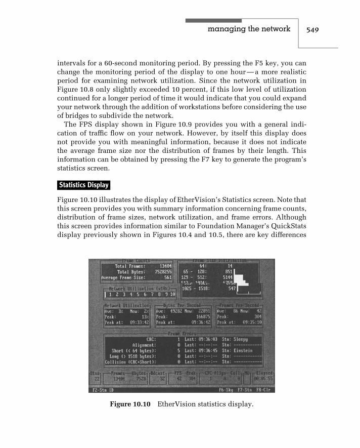
managing the network 549
intervals for a 60-second monitoring period. By pressing the F5 key, you canchange the monitoring period of the display to one hour — a more realisticperiod for examining network utilization. Since the network utilization inFigure 10.8 only slightly exceeded 10 percent, if this low level of utilizationcontinued for a longer period of time it would indicate that you could expandyour network through the addition of workstations before considering the useof bridges to subdivide the network.
The FPS display shown in Figure 10.9 provides you with a general indi-cation of traffic flow on your network. However, by itself this display doesnot provide you with meaningful information, because it does not indicatethe average frame size nor the distribution of frames by their length. Thisinformation can be obtained by pressing the F7 key to generate the program’sstatistics screen.
Statistics Display
Figure 10.10 illustrates the display of EtherVision’s Statistics screen. Note thatthis screen provides you with summary information concerning frame counts,distribution of frame sizes, network utilization, and frame errors. Althoughthis screen provides information similar to Foundation Manager’s QuickStatsdisplay previously shown in Figures 10.4 and 10.5, there are key differences
Figure 10.10 EtherVision statistics display.

550 c h a p t e r t e n
between that program and EtherVision that deserve a brief discussion. Foun-dation Manager is an SNMP RMON manager, capable of monitoring up to eightremote LANs. In comparison, EtherVision requires you to run the programon a station on the network to be monitored and does not support remotemonitoring. Thus, you would use Foundation Manager or a similar product ifyou need to monitor remote networks while EtherVision or a similar productcould be used to monitor a local network. Returning to our discussion ofEtherVision, note that in the Frame Counts window, the average computedframe size is displayed, while the Frames Per Second window displays theaverage and peak frames per second monitored on the network. By using thisdata, you can compute and verify the data in the Network Utilization windowand compute the effect of adding additional workstations to the network. Forexample, the peak FPS rate is 304 for 22 stations, or approximately 14 FPS perworkstation. Adding 10 workstations with similar operational characteristicsto existing workstations can be expected to increase the network traffic flow by140 FPS. Since the average frame size is 561 bytes, 10 additional workstationscan be expected to result in 561 bytes × 8 bits per byte × 140 FPS, or less than630,000 bps of network traffic.
Alarms
The key to the effective management of a network is the ability to generatealarms when important predefined events occur. EtherVision provides net-work administrators with the ability to generate several key alarms, withoutwhich you would have to monitor several screens constantly. You can avoidthis cumbersome process by using the program’s Network Alarms/Optionsscreen, illustrated in Figure 10.11. The Network Alarms/Options screen illus-trated in Figure 10.11 allows you to enable or disable five alarms and to setthe threshold value for three alarms. When an alarm is enabled and the eventoccurs or an alarm threshold is exceeded, the alarm status will be displayedon the top line of any EtherVision screen you are using, as well as beingwritten to the program’s Network Event Log.
The network idle time alarm will be triggered when EtherVision senses notraffic for the specified period of time. Since NetWare file servers periodicallytransmit IPX frames to make servers aware of each other, a Novell-basedEthernet LAN will always have at least some traffic at periodic intervals.Thus, the occurrence of a network idle time alarm can inform you of a seriousnetwork problem, such as the failure of a server or a faulty adapter in thecomputer operating EtherVision.
The network utilization alarm allows you to determine whether your net-work is approaching or has reached a level of saturation that warrants its

managing the network 551
Figure 10.11 EtherVision network alarms/options screen.
subdivision. Normally, a utilization level that periodically exceeds 50 percenton an Ethernet/IEEE 802.3 network indicates a level of use that warrants thesubdivision of the network and its connection via a bridge.
The frame error alarm goes off when it reaches a specified number of frameerrors. Since the error rate on a LAN is typically 1 in a billion bits, or 1 × 10⁻⁹,you can use this alarm to determine whether your network has an acceptableerror level. To do so, you would view the Statistics screen when a frameerror alarm occurs to determine the number of bits that have been transmittedduring the time it took until the frame error alarm was generated. With thisinformation, you could determine whether your LAN’s bit error rate (BER)is at an acceptable level. For example, assume the total number of framesin the frame count window in the Statistics display was 100,000,000 whenthe frame error count reached 100 and generated an alarm. Also assume, forsimplicity, that the average frame size in the Statistics display was 1000 bytes.An average of 100,000,000/100, or 1,000,000 frames, flowed on the networkfor each frame error. Since we assumed that each frame has an average lengthof 1000 bytes, 1,000,000 frames × 1000 bytes per frame × 8 bits per byte, or8,000,000,000 bits, are transmitted per frame error. This is equivalent to a BERof 1/8,000,000,000, or 1.25 × 10⁻⁸, which is about what we would expect froma LAN that performs well, and that has properly connected cables routed asafe distance from sources of electromagnetic interference.
The alarm count interval can be used to generate an alarm when enabledand set to a specific time period. Then, if the number of frame errors specified

552 c h a p t e r t e n
by the frame error alarm occurs within the specified alarm period, an alarmframe count interval alarm will go off.
The intruder detection alarm operates by triggering an alarm when a newstation enters the network that was not defined to the program by the assign-ment of a logical name. When we examine the Station Options screen, we willsee how logical names are assigned to each station address. The last alarmshown in Figure 10.11 is Source Addr = Broadcast Alarm. Since all sourceaddresses must be unique, this alarm occurs when a source address with itsbroadcast bit set is detected.
Station Options Display
Through EtherVision’s Station Options display screen you obtain the abilityto assign names, filters, and alarms to specific hardware adapter addresses.Figure 10.12 illustrates the display of the program’s Station Options screen.
In examining Figure 10.12, note that the highlighted bar is positioned overthe top address, which was previously assigned the logical name Sleepy. Inthis example, we are in the process of changing the station’s name to Dumbo.By moving the highlight bar over different station addresses and/or pressingappropriate function keys, you can control the assignment of names, alarms,and filters to stations. For example, F2 permits you to add or change a name,F3 prompts you to delete the name currently selected by the highlight bar,and so on. When assigning names, you can specify a filter (Ftr) for eachstation. Then, during monitoring, only those stations marked for filtering
Figure 10.12 EtherVision station options display.

managing the network 553
will be displayed on the program’s monitoring screen. For a large network,filtering enables you to examine groups of stations, such as the accountingdepartment’s workstations. In addition to station filtering, you can use theStation Options display to set an idle alarm from 1 to 9,999, an error alarmof 1 to 9,999, and a usage alarm based on a percentage of network activityfor each station. Thus, you can use the Station Options display to isolate aproblem condition on a specific station or group of stations.
Network Event Logging Display
Figure 10.13 illustrates EtherVision’s Network Event Logging screen. Fromthis screen, you can enable and disable the logging of events to the program’slog file and select the logging of error frames and peak utilization data. Inaddition, from this screen you can view the event log.
Figure 10.14 displays a portion of the network event log, which can bescrolled through a window on your display. Since we previously enabledthe logging of both frame errors and peak utilization, the contents of the logreflect both types of activities. In examining Figure 10.14, note that ‘‘FrameShort’’ refers to any frame shorter than the minimum length of 64 bytes — acondition usually caused by a collision. Although collisions normally occuron an Ethernet/IEEE 802.3 network, a situation in which one station has alarge number of collisions associated with its transmission may indicate afaulty adapter. Thus, from an examination of Figure 10.14 it appears that the
Figure 10.13 EtherVision network event logging screen.

554 c h a p t e r t e n
Figure 10.14 EtherVision network event log.
adapter used on the station whose logical address is Sleepy may be in need ofan awakening action, during which the adapter is tested, and if it continuesto generate short frames, replaced.
As indicated by our short review of EtherVision, it permits you to performmost of the major functions associated with network management. Regardlessof which management tool you use, you should always ensure that you haveone available. The periodic use of an appropriate network management toolprovides you with a detailed view of network activity, which can be invaluablein performing your network management functions.
Cinco Network’s WebXRay
As previously discussed in this chapter, it is important to note that Ethernetis a layer 2 transport protocol that operates at the data link layer of theISO Reference Model. This means that different types of protocols can betransported over Ethernet, which is both a key advantage of the networkas well as the cause of many network-related problems. In this section wewill turn our attention to the use of Cinco Network’s WebXRay networkmonitoring and troubleshooting tool, which can be of considerable assistancewhen looking at IP traffic. As noted earlier in this chapter, Cinco Networkswas one of several companies acquired by Network Associates over the pastfew years. WebXRay is now marketed as Sniffer Basic by Network Associates.Due to the growing role of the Internet and corporate intranets, most Ethernet

managing the network 555
LANs carry a considerable amount of IP traffic, and the use of this programcan provide a valuable tool for examining the state of different IP machinesand the traffic they transmit and receive.
Overview
Figure 10.15 illustrates the WebXRay Dashboard, which provides a metergauge view of IP statistics when the program is initialized. The top gaugedisplays the IP versus network load in terms of the number of packets persecond. The next gauge indicates IP versus network utilization. In examiningFigure 10.15 note that at the time the display was captured IP was contributing39 percent of network utilization, with all traffic resulting in a networkutilization level of 42 percent. This indicates that IP is the predominateprotocol transported on the monitored network and any need to restructurethe network due to high levels of utilization will have to consider thearchitecture of IP and its addressing.
Autodiscovery
One of the key features of WebXRay is its autodiscovery capability. Throughthe use of this feature you can use the program to identify all hosts on asegment as well as the IP services they are currently configured to support.
Figure 10.15 Cinco Network’s WebXRay’s Dashboard provides a meter orgauge display, which enables the role of IP traffic on a network to be visu-ally noted.

556 c h a p t e r t e n
Figure 10.16 Through the Topology Discovery dialog box you can configureWebXRay to search for a specific range of host addresses.
Figure 10.16 illustrates the WebXRay Topology Discovery dialog box. Intothis box you enter the IP subnet address and the range for the last digit ofthe IP address you wish to search for. Since the WebXRay program usesthe Ping application to locate hosts, it also provides you with the ability toset the timeout value for each ping. In the example shown in Figure 10.16,we will search the entire segment by using the last digit address range of 1through 254 since 0 means this net and 255 is a broadcast address. A word ofcaution is in order concerning the entry of a Ping timeout value and host searchrange. If you set a very large Ping timeout value, a full search of a networksegment for a large number of services per host can take a considerable amountof time.
To specify the services you wish to discover, you would click on the servicetab of the Topology Discovery dialog box, generating a display similar to theone shown in Figure 10.17. In Figure 10.17 the selected services for DNS,FTP, HTTP, SNMP, and Telnet are shown checked. This means that theautodiscovery program will search each possible host address on the segmentfor the range of network values specified to determine if a host supports theservices of interest.
Once you click the OK button in Figure 10.17 the autodiscovery processcommences. As each node on the segment is discovered, its domain namewill be displayed. If the domain name cannot be found, the IP address ofthe discovered node will be shown. Figure 10.18 illustrates a portion of the
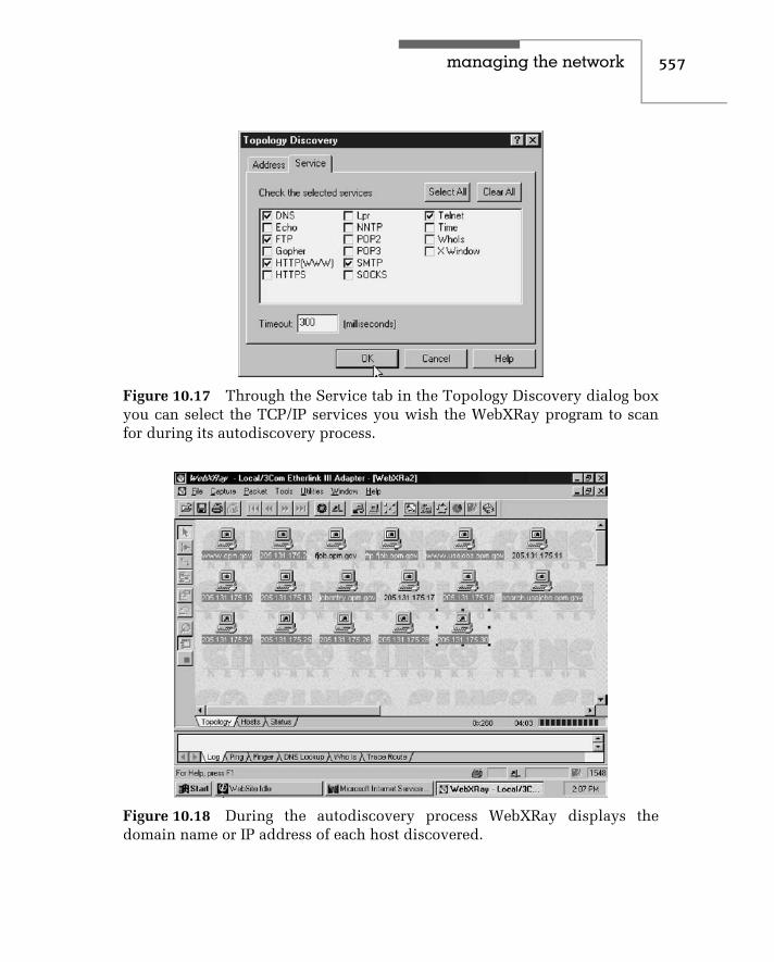
managing the network 557
Figure 10.17 Through the Service tab in the Topology Discovery dialog boxyou can select the TCP/IP services you wish the WebXRay program to scanfor during its autodiscovery process.
Figure 10.18 During the autodiscovery process WebXRay displays thedomain name or IP address of each host discovered.

558 c h a p t e r t e n
autodiscovery process at a point in time when 17 nodes were discoveredon the segment being monitored. As you might surmise, the autodiscoveryfeature represents a valuable mechanism to discover unknown machines usersmay have set up without informing management as well as services on thosesystems that might require a reconfiguration of a router’s access list or firewall.Thus, a periodic autodiscovery process is usually a very valuable procedurefor employing on a large network.
Once the autodiscovery process is completed you can determine the statusof each service for each node discovered. To do so, you would click on thestatus tab at the bottom of the map window shown in Figure 10.18. Thisaction will result in the display of the service window which is shown inFigure 10.19. In examining Figure 10.19 note that a happy face means the nodeor service is up and available, a question mark indicates that the status of theservice is unknown, while a minus sign enclosed in a circle means that theservice is not available for the network node. Since we previously indicatedwe wanted to restrict our service queries to specific types of services, thoseservices with question marks primarily represent services we did not have theprogram query.
Figure 10.19 The WebXRay Service window indicates the status of differentTCP/IP services or applications for each autodiscovered node on a segment.

managing the network 559
As indicated by our examination of WebXRay, this program is well-suitedfor determining the effect of IP on your LAN and discovering nodes andthe services they are configured to support. As such, WebXRay providesan additional insight into the activity on an Ethernet network that can beof considerable assistance in obtaining information on the operations andutilization of the network.
Wildpackets EtherPeek
In this concluding section of this chapter focused on network management,we will turn our attention to one of the most feature-packed Ethernet networkmonitoring and analysis programs. That program is EtherPeek, a product ofWildPackets of Walnut Creek, CA. that was formerly known as the AG Group.
Overview
EtherPeek represents a full featured network monitoring and analysis softwareprogram. Unlike EtherVision, which is restricted to layer 2 monitoring, Ether-Peek has the ability to look deeper into a frame and determine and analyzeinformation contained in each frame. For example, EtherPeek can read IP,UDP and TCP headers being transported in Ethernet frames. This enablesthe program to construct tables of data concerning source and destination IPaddress packet flows, tables concerning the distribution of protocols flowingon the network and similar information.
Operation
Figure 10.20 illustrates the EtherPeek main window with its two gauges shownin the lower portion of the display. The left gauge indicates network utilizationwhile the right gauge indicates the packet rate. By checking on the tab labeled‘‘value,’’ you can display digital information in place of the analog gauges oryou can close the lower window by checking on the X in the lower window’stop left corner.
The top portion of the EtherPeek main window contains a series of menuentries that can be used to perform a variety of functions. You can capturedata to a buffer, store captured data and analyze previously captured data at alater time or send captured data via email to a vendor’s help desk for review.Because modern Ethernet LANs operating at 100 Mbps or 1 Gbps create asignificant packet flow, you will probably want to use filters to restrict thetype of packets to be captured, which represents another feature or EtherPeekwe will examine later in this section.

560 c h a p t e r t e n
Figure 10.20 The EtherPeek main window with the network activity gaugeshown in the lower portion of the display.
Packet Capturing
Through the File menu you can initiate the capturing of packets. To do soyou would select the New entry in the File menu, which would generate thedisplay of a dialog box labeled Capture Buffer Options. You would use thisdialog box to set the buffer size that controls the amount of data that can becaptured, as well as other data capture options.
Figure 10.21 illustrates an in-progress data capture operation. As data iscaptured, EtherPeek displays key information about each packet captured.Such information includes the source and destination address of the packet,its size in bytes, the time it was captured, the protocol used to transportthe packet, and other information. To facilitate packet reference EtherPeekdisplays a packet number, which is shown in the left column in Figure 10.21.In addition, EtherPeek provides the ability for a user to perform a series ofpacket captures and to display the packet in each packet capture operation. InFigure 10.21 a portion of the packet captured during a second packet captureoperation is shown displayed.
As a packet capture operation progresses EtherPeek updates the number ofpackets received, filtered and processed. While all three values are shown to

managing the network 561
Figure 10.21 An EtherPeek in-progress packet capture operation.
be the same in Figure 10.21, this is because no filtering was performed and theprocessor of the computer operating EtherPeek was sufficiently fast to keepup with the flow of packets.
In Figure 10.21 the screen capture occurred when the capture buffer was46 percent filled. In Figure 10.22 the capture buffer was completely filled,which is indicated by memory usage being shown as 100 percent. A total of7401 packets were captured based upon the use of a 4 Mbyte capture buffer,which represents the default setting of the size of the buffer. Because RAMmemory has become relatively inexpensive, most readers acquiring modernPCs to run an Ethernet monitoring and analysis program would more thanlikely select a large buffer size for packet capture.
Packet Decoding
One of the key features of EtherPeek is the ability to decode packets ofinterest easily. To illustrate this capability, let’s assume you wish to decodethe packet that flowed from IP source address 157.130.74.98 to destinationaddress 205.131.176.11. This is the third packet shown in Figure 10.22 and ishighlighted in the display.

562 c h a p t e r t e n
Figure 10.22 Using EtherPeek to select a packet for decoding.
Double-clicking on an entry in the packet capture window results inEtherPeek automatically decoding the packet. Figure 10.23 illustrates thedecoding of the third packet captured that was summarized in Figure 10.22.In examining Figure 10.23 you will note that the beginning of the packetdecode provides summary information about the packet, such as its lengthand timestamp.
The actual beginning of the decode follows the summary information. As youwill note from Figure 10.23, information about the Ethernet frame transportingthe IP packet indicates the destination and source MAC addresses in the frame.This is followed by the value in the Type field, which indicates that IP isbeing transported.
The Ethernet header decode is followed by a decode of the IP header. Ifyou go back to our earlier coverage of the IP header, you will note that thepacket decode indicates the value of each field in the IP header. If we scrolleddown further, we would also note the decode of the TCP header. If you focusyour attention on the window above the gauge window, you will note that itconsists of a sequence of hex characters. As you move the highlight bar fromone entry to another in the top window, the applicable hex character thatcorresponds to the value of a field is highlighted. Thus, the hex characters
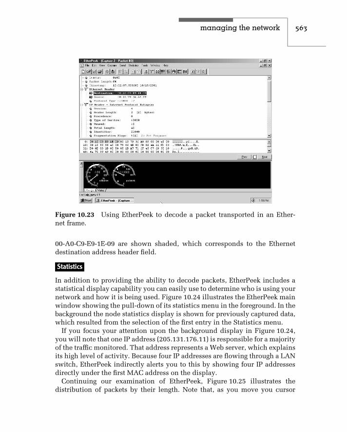
managing the network 563
Figure 10.23 Using EtherPeek to decode a packet transported in an Ether-net frame.
00-A0-C9-E9-1E-09 are shown shaded, which corresponds to the Ethernetdestination address header field.
Statistics
In addition to providing the ability to decode packets, EtherPeek includes astatistical display capability you can easily use to determine who is using yournetwork and how it is being used. Figure 10.24 illustrates the EtherPeek mainwindow showing the pull-down of its statistics menu in the foreground. In thebackground the node statistics display is shown for previously captured data,which resulted from the selection of the first entry in the Statistics menu.
If you focus your attention upon the background display in Figure 10.24,you will note that one IP address (205.131.176.11) is responsible for a majorityof the traffic monitored. That address represents a Web server, which explainsits high level of activity. Because four IP addresses are flowing through a LANswitch, EtherPeek indirectly alerts you to this by showing four IP addressesdirectly under the first MAC address on the display.
Continuing our examination of EtherPeek, Figure 10.25 illustrates thedistribution of packets by their length. Note that, as you move you cursor

564 c h a p t e r t e n
Figure 10.24 EtherPeek provides the ability to display several types of statis-tics concerning a monitored LAN.
Figure 10.25 Displaying packet size distribution information.

managing the network 565
over each slice of the pie, the program displays specific statistics concerningthe slice.
You can display the packet size distribution, as well as other statistics, inseveral ways when using EtherPeek. As noted in Figure 10.24, you can select‘‘size’’ from the statistics menu or press Ctrl + 6. You can also click on the pieicon to display the pie chart.
Filtering
In concluding our examination of EtherPeek, we will focus our attentionupon the program’s filtering capability. EtherPeek’s filtering capability canbe applied to real-time as well as previously captured packets. Through theuse of the program’s packet filtering capability you can focus on an area ofparticular interest, such as a certain IP address or protocol.
Figure 10.26 illustrates the Edit Filter dialog box. In this example the filterwas set to filter on the IP protocol, while the address to be filtered is shown as205.131.176.11. In this example we want to filter packets with that IP sourceaddress but do not care about the destination address. In the lower portion
Figure 10.26 Using the EtherPeek filtering capability to focus on specifictypes of packets.

566 c h a p t e r t e n
of Figure 10.26 we will filter on source port 80 but do not care about thedestination port. If you examine the background of Figure 10.26 you will notethe large number of protocols EtherPeek supports, ranging from AppleTalkto NetWare. Thus, EtherPeek provides a significant capability for monitoringEthernet networks that transport a wide range of higher-layer protocols.

c h a p t e r e l e v e n
The Future of EthernetWhen a book is devoted to a well-defined technology, it is always importantto discuss the future of that technology. This is especially true with respectto Ethernet, since many readers are employees of organizations that haveinvested or plan to invest tens to hundreds of thousands of dollars or morein acquiring network adapter cards and hubs or switches, installing cabling,obtaining software, and teaching employees to use a network operating system.Thus, a logical question readers may have involves the safety of their current orplanned investment in Ethernet technology. That is, what can you expect in theevolution of Ethernet technology, and will the introduction of new technologyresult in the obsolescence of your existing or planned Ethernet network?Although there is no simple answer to this multifaceted question, sincethe effect of technological advances is highly dependent on organizationalcommunications requirements, we can examine trends in networking andEthernet technology. This will provide us with a foundation of knowledgefrom which we can express some general observations about a previous orplanned investment in an Ethernet network.
11.1 Ethernet TrendsIn attempting to project the future of Ethernet, we should consider a varietyof variables in addition to technological developments. Some of the majorvariables we must consider are the cost of technology, the performance itprovides, and the potential to use existing technology in a more productivemanner. The latter may minimize or reduce a requirement to migrate tonew technology. In this section, we will focus our attention on the cost andperformance of existing and evolving Ethernet technology.
Network Adapter Card CostJust a half-dozen years ago, the average price of an Ethernet adapter card wasapproximately $1000, while the cost of a personal computer was between
567

568 c h a p t e r e l e v e n
$3000 and $4000. Excluding the cost of cabling and a network operatingsystem, an Ethernet adapter card represented an approximate 25- to 33-percentincrease in the cost of a personal computer. By early 2002 you could acquirean Intel Pentium IV–based personal computer with 256 M of RAM, SVGAsupport, and an SVGA monitor for approximately $1000. At the same time, theaverage cost of a 10-/100-Mbps dual-speed Ethernet adapter card was under$50, so the additional cost to network a personal computer was only approx-imately 5 percent of an organization’s hardware budget. Clearly, the costof obtaining an Ethernet network communications capability was extremelynominal by 2002.
Future Price Direction
Not only has the cost of Ethernet hardware significantly declined over thepast few years, but advances in chip fabrication technology indicate that pricedeclines are far from being over. In 1992 Zenith Data Systems introducedseveral notebook computers with a built-in Ethernet communications capabil-ity on the computer’s motherboard. Additional computer manufacturers nowprovide a built-in Ethernet networking capability for their products, enablingportable computer users to simply plug a dual-speed 10/100BASE-T jackinto their computer’s plug upon return to the office to obtain access to thecorporate network.
According to several trade press articles, the inclusion of an Ethernetchip set on nonportable personal computers adds less than $20 to the costof the computer. This can be expected to make an Ethernet networkingcapability on personal computers as pervasive as the inclusion of a parallelport. In comparison, alternative network adapter cards, such as Token-Ringand FDDI, range in cost from $150 to $200 for a 16-Mbps Token-Ring adapterto $400 to $550 for an FDDI adapter. Ethernet can thus be expected tocontinue to hold a significant cost advantage over competing local areanetwork adapter cards. This should extend the use of Ethernet networks farinto the foreseeable future.
In the area of desktop personal computers, it is almost a common occurrenceto note approximately 25 percent of all advertisements now include either abuilt-in NIC or a 10-/100-Mbps adapter bundled with memory, an SVGA videoadapter, and other computer features. Thus, not only is Ethernet recognizedas the de facto network of choice, but, in addition, a significant number of PCsare now being bundled with Ethernet adapters.
Although the cost of Gigabit Ethernet adapter cards was relatively expensivein comparison to 10-/100-Mbps adapters, the cost of the former is rapidly

the future of ethernet 569
declining. First introduced at prices above $2000, by early 2002 some GigabitEthernet adapters were priced below $1000. However, it is important to notethat currently available Gigabit Ethernet adapters are based upon relativelyexpensive optical technology. As more vendors produce recently standardized1000BASE-T network adapter cards, you can reasonably expect production ofadapters using that media to achieve significant levels of production that canresult in economics of scale, which lowers the cost of production. This in turnwill eventually result in declining prices for 1000BASE-T adapter cards as themarket for this product grows.
Although 10 Gigabit Ethernet is primarily expected to be used by largeorganizations and communications carriers in a metropolitan networkingenvironment, we can also expect the cost of such equipment to decline asproduction increases. Thus, the cost per port of $20,000 or more for many10 Gigabit switches entering the market during 2002, while out of reach forsmall to medium-size organizations, can be expected to become more nom-inal for use by large organizations. In fact, one of the most promising usesfor 10 Gigabit Ethernet is as a supplement or replacement for SynchronousOptical Networking (SONET) equipment in a metropolitan networking envi-ronment, so let’s turn our attention to this potential use of a developingEthernet technology.
10 Gigabit Ethernet in the Metro
During 2002 the IEEE 802.3ae Committee’s draft standard for 10 GigabitEthernet LAN and WAN implementations should be ratified. As a dominantLAN protocol a 10 Gbps standard could result in 10 Gigabit Ethernet becomingprice competitive for use in the WAN at distances up to 40 km, in effect ametropolitan area networking capability.
To understand the rationale for the potential use of 10 Gigabit Ethernet in theWAN it is important to note that most metropolitan area networking currentlyconsists of SONET-based technology. Under SONET, data is transported inframes that have a high amount of fixed overhead, with overhead bits usedto convey many types of administrative data between nodes, as well asto support voice calls of repair personnel. SONET was developed in a pre-wireless communications era. It was also deployed prior to the development ofoptical switching and dense wavelength division multiplexing. While SONETincludes the capability to have redundant rings with cutover from one toanother in milliseconds when a fiber is out, there are less expensive evolvingsolutions today that provide a similar capability. One of those evolvingsolutions is the use of 10 Gbps Ethernet in the WAN.

570 c h a p t e r e l e v e n
In comparison to SONET, which represents a complex technology withcomplex framing, 10 Gigabit Ethernet represents a scalable extension of awell-understood technology. Prices per port of all types of Ethernet equipmentroutinely decline 20 to 30 percent per year, with 10 Gigabit Ethernet perport cost expected to decline to $10,000 to $15,000 by the end of 2002. Incomparison, packet over SONET interfaces cost over 20 times that amount.In addition, the mapping of Ethernet to ATM that is also commonly used inthe WAN represents another well-known technology. Thus, it probably willbecome practical for some large organizations to use a 10 Gigabit Ethernetconnection to a carrier’s ATM backbone in place of a SONET local loop.
Table 11.1 provides a comparison of Gigabit Ethernet and 10 Gigabit Ether-net. Note that the maximum drive distance of 10 Gigabit Ethernet is 40 km,which makes it well suited for both high-speed local loop and metropolitanarea transmission.
To illustrate the potential use of Gigabit and 10 Gigabit Ethernet in ametropolitan area networking environment, consider Figure 11.1. In thisexample a Gigabit Ethernet and 10 Gigabit Ethernet local loop flow into acommunications carrier’s central office. That office routes metro transmissionvia Ethernet switches or SONET equipment to their applicable destination.Thus, if the destination is within the metro area, the data would be carriedvia a 10 Gigabit Ethernet switch infrastructure to the central office serving thedestination local loop.
TABLE 11.1 Gigabit Ethernet vs. 10 Gigabit Ethernet
Attribute Gigabit Ethernet 10 Gigabit Ethernet
Physical media Single-mode fiber,multimode fiber, widewavedivision multiplexing,twisted-pair copper
Single-mode fiber,multimode fiber
Drive distance Up to 5 km (3.11 miles) Up to 40 km (24.86 miles)
Media AccessControl
Full and half duplex Full duplex
Coding 8B/10B 64B/66B and Sonet framing
Physical-mediadependent
805 nm; 1300 nm, 1550 nmWWDM
850 nm; 1300 nm; 1550 nm
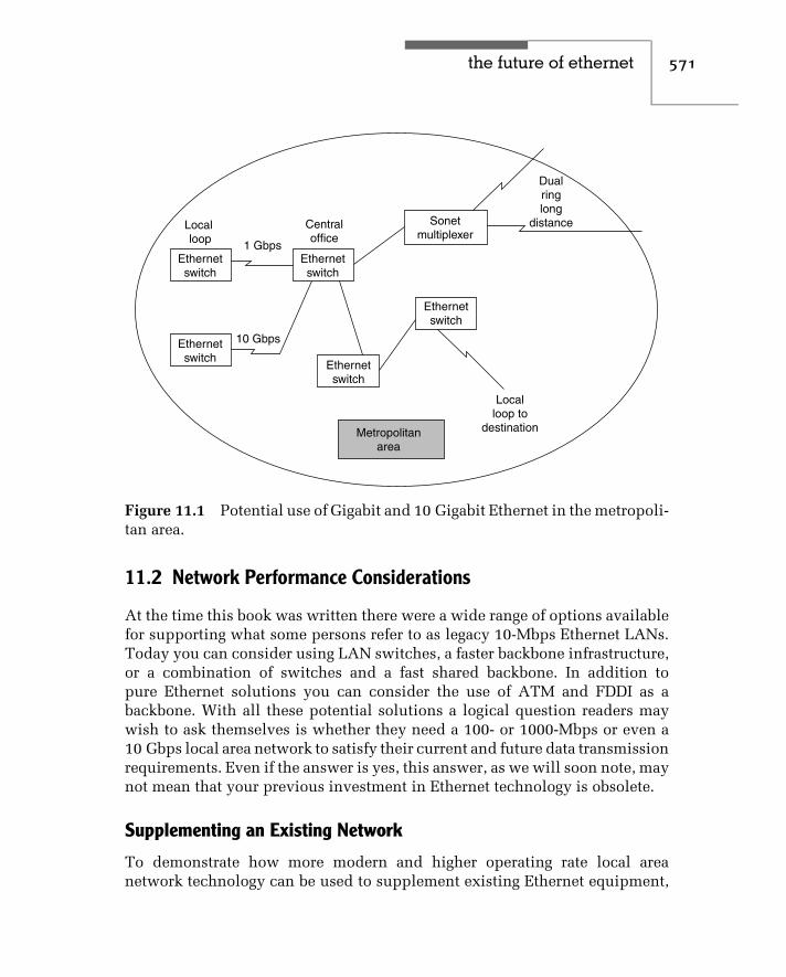
the future of ethernet 571
Sonetmultiplexer
Dualringlong
distance
Localloop to
destination
Ethernetswitch
Ethernetswitch
Ethernetswitch
Ethernetswitch
Ethernetswitch
Centraloffice
1 Gbps
10 Gbps
Localloop
Metropolitanarea
Figure 11.1 Potential use of Gigabit and 10 Gigabit Ethernet in the metropoli-tan area.
11.2 Network Performance Considerations
At the time this book was written there were a wide range of options availablefor supporting what some persons refer to as legacy 10-Mbps Ethernet LANs.Today you can consider using LAN switches, a faster backbone infrastructure,or a combination of switches and a fast shared backbone. In addition topure Ethernet solutions you can consider the use of ATM and FDDI as abackbone. With all these potential solutions a logical question readers maywish to ask themselves is whether they need a 100- or 1000-Mbps or even a10 Gbps local area network to satisfy their current and future data transmissionrequirements. Even if the answer is yes, this answer, as we will soon note, maynot mean that your previous investment in Ethernet technology is obsolete.
Supplementing an Existing Network
To demonstrate how more modern and higher operating rate local areanetwork technology can be used to supplement existing Ethernet equipment,

572 c h a p t e r e l e v e n
let us assume that your organization previously installed a series of Ethernetnetworks on floors within a building, using 10BASE-T bridges and wiringthrough floor risers to interconnect users on each ‘‘floor’’-based network.Under this networking scenario, it is quite possible that the initiation of afile transfer operation by two or more network users accessing a server on athird network via a 10BASE-T bridge would adversely affect other internettransmission until the file transfer operations are completed.
To see this potential for internet congestion, consider Figure 11.2, in whichthree ‘‘floor’’ LANs are connected with three 10BASE-T bridges wired together,perhaps using the riser within the building. Let us assume that stations A andC initiate file transfers to the server Sn located on network C. If each networkoperates at 10 Mbps, the traffic offered to the middle bridge is 20 Mbps.However, since each network operates at 10 Mbps, the best performancepossible for the middle bridge is to route the file transfer data at 10 Mbps tothe server. Now suppose that station D on network B attempts to access theserver S on network C. Frames generated by that station must contend withframes generated by workstations A and C for service by the bridge. It is thusquite possible for interactive queries, as well as file transfer operations acrossnetworks, to be adversely affected by existing file transfer operations.
B
D
E
A
C
FSn
Sn
A F
Legend:
= Workstations
= Servern
to
Bridge
Bridge
Bridge
Network A
Network B
Network C
Figure 11.2 Potential for internetwork congestion. The initiation of file trans-fer operations from two or more workstations to a server on a third workstationcan create network congestion.

the future of ethernet 573
Using a Backbone Network
Although one potential solution to internet congestion is to install newnetworks capable of supporting higher data transfer operations, doing so mightrequire both new adapter cards and new network wiring. A far less expensivepotential solution to internet congestion is to use a higher operating rate localarea network to serve as a backbone net.
Figure 11.3 shows the use of an FDDI backbone network to interconnect thethree previously installed Ethernet networks. Since the FDDI network operatesat 100 Mbps, its use is equivalent to a high-speed interstate highway linkingcountry roads together. That is, inter-LAN traffic is facilitated by a high-speedbackbone LAN in the same manner that interroad traffic is facilitated by aninterstate highway. Once a frame is bridged onto the FDDI network, it flowsat 100 Mbps, enabling more frames to be carried between linked local areanetworks per unit time than possible when a 10BASE-T network is used as abackbone network.
Unless your organization is already using FDDI, its installation cost can berelatively expensive in comparison to 100BASE-T technology. Thus, manyorganizations will more than likely consider the use of a 100BASE-T sharedmedia hub or even a 1-Gbps buffered distributor to form a network backbone.
In early 2002, the cost of an 8-port 100-Mbps shared Ethernet hub wasunder $100, providing a most economical method for creating a higher-speed
Bridge
Bridge
Bridge
Network A
Network B
Network C
FDDIbackbonenetwork
Figure 11.3 Using a high-speed backbone network. The use of a 100-MbpsFDDI network as a backbone to connect separate Ethernet LANs can removea large degree of potential internet congestion while permitting the previousinvestment in Ethernet networks to be maintained.

574 c h a p t e r e l e v e n
Network A
Network B
Network C
Bridge
Bridge
Bridge
100 Mbpsshared
ethernethub
Figure 11.4 Using a 100-Mbps shared Ethernet hub as a backbone providesa very low-cost mechanism for supporting inter-LAN communications.
backbone network for bridging between LANs. Figure 11.4 illustrates howyou could use a low-cost 100-Mbps shared Ethernet hub as a backbone forconnecting legacy 10BASE-T networks. Note that this network configurationalso preserves your investment as all cabling and network adapters to the leftof each bridge remain as is. Since the cost of a 100-Mbps shared Ethernet hubis equivalent to the cost of a single FDDI adapter, this represents a low-costmechanism to retain your network infrastructure.
In examining Figure 11.4, note that transmission from any bridge port tothe 100-Mbps shared Ethernet hub is regenerated onto all other hub ports.However, the use of bridges on each network connection serves as a filter,barring repeated frames from flowing onto networks they are not intendedfor. Thus, although each network could be directly connected to a hub port,the use of bridges can significantly enhance network performance by limitingrepeated frames from destination networks they are not actually directed to.
Using a Switching System
Another solution to network congestion can be obtained through the use ofa 100BASE-T Fast Ethernet switch or creating a tiered hub-based switch-ing network.
Figure 11.5 illustrates the use of a Fast Ethernet hub-based switch. Inthis example, network servers are connected to the 100-Mbps Fast Ethernetports, while existing 10BASE-T hubs are connected to the switch using10BASE-T adapters operating at 10 Mbps. Note that the switch can provide

the future of ethernet 575
•
• •
• •
Fileserver
Fileserver
Ethernetswitching
Conventionalhub
Conventionalhub
10 Mbps
100 Mbps
Figure 11.5 Constructing a tiered net-work.
two simultaneous cross-connections to the two file servers, boosting availablebandwidth in comparison to the situation where file servers are located ona common network. In addition, through the use of a 100-Mbps connectioneach query response is completed quicker than if communications occurredon a shared 10-Mbps network.
The configuration illustrated in Figure 11.5, which this author labeled asa tiered network, can also be considered to represent a collapsed backbone.Although a switch using two Mbps Fast Ethernet port connections to twofile servers is shown, there are many other network connections that can beconsidered to protect your investment in 10-Mbps Ethernet technology whileproviding a mechanism to reduce network congestion. You can consider theuse of a switch with a fat pipe or full-duplex capability, or the use of a routeras an alternative to the use of a switch.
Although the use of a switch or router can provide a mechanism to alleviatenetwork congestion, another method you can consider is the bottleneckbetween workstations, servers, and the network. That bottleneck is the LANadapter card. Many times the use of an enhanced adapter card may solvea network congestion problem many consultants would have you believerequires the use of a more expensive solution.
Using Enhanced Adapter Cards
One of the key limits to the ability of a workstation to transfer large quantitiesof data is the type of network adapter card used in a workstation. A typical

576 c h a p t e r e l e v e n
low-cost Ethernet adapter card may have a data transfer rate of only 200,000to 400,000 bytes per second. Such adapters are capable of transmitting andreceiving data at only approximately 10 to 20 percent of the transfer rate of a10BASE-T network. While this transfer rate is usually more than sufficient formost client/server operations, it becomes a bottleneck for long file transfersand for devices such as bridges, routers, and gateways that may require ahigher transfer rate capability. The selective use of enhanced Ethernet adaptercards may provide you with the ability to increase network performance andreduce or eliminate network bottlenecks.
Two types of Ethernet adapter cards you may wish to consider for worksta-tions that have a large amount of file transfer operations or for bridges, routers,and gateways are bus mastering and parallel processing adapter cards.
Bus Mastering Cards A bus mastering card is designed to perform I/O datatransfers directly to and from the memory of the computer in which it isinstalled. To accomplish this, a bus mastering card includes circuitry knownas a direct memory access (DMA). The adapter card can initiate a DMAtransfer, which permits data to be moved directly to or from memory, whilethe processor on the adapter card performs other operations. The net effect ofbus mastering is to increase the transfer capability of the adapter card by 50to 100 percent.
Parallel-Tasking Cards Standard Ethernet adapter cards perform network-ing operations in a fixed sequential manner. Although a bus mastering adapterpermits memory access operations to be performed in parallel with somenetwork operations, greater efficiencies are obtainable with the use of parallel-tasking Ethernet adapters. One such adapter is Etherlink III, manufactured by3Com Corporation, which has the capability to transfer data at approximately500,000 bytes per second.
To demonstrate the efficiency of parallel-tasking, the top portion ofFigure 11.6 shows the operation of a pair of standard Ethernet adaptersused to transmit and receive data. As indicated, each operation has to becompleted before the next can be begun.
The lower portion of Figure 11.6 shows the tasks performed for the trans-mission of information between two parallel-tasking Ethernet adapter cards.As noted by the time chart, the performance of many tasks in parallel reducesthe time required to transfer information, which enhances the transfer rate ofthe adapter card.
100-Mbps Adapter Operations Although the use of appropriate 10BASE-Tadapter cards may by themselves prolong the ability to operate at 10 Mbps,

the future of ethernet 577
Frameencoded
Frameencoded
Placedon driver
Placedon
driver Placedonbus
Placedon bus Transfer
on wire
Transferon wire
Transferoff bus
Transferoff bus
Offdriver
Off driver
Framedecoded
Framedecoded
Parallel tasking
Time
Figure 11.6 Serial-tasking versus parallel-tasking Ethernet adapters. The useof parallel-tasking Ethernet adapter cards permits the overlapping of manyoperations, thus reducing the time needed to transfer information and increas-ing the data transfer capability of the adapter.
when upgrading to 100-Mbps Fast Ethernet or another network, you mustalso carefully consider the capability of adapter cards. For example, assumeyour organization’s 10BASE-T network is heavily saturated and additionalapplications to include multimedia are on the horizon. Although upgrading toa 100BASE-T network might initially satisfy your organization’s networkingrequirements, it is quite possible that access contention to a video server, evenat 100 Mbps, could result in delays that distance the delivery of video. In thissituation you might consider installing a full-duplex 100BASE-T adapter cardin the video server and connecting the server to a 100-Mbps switching hub.
1000-Mbps Adapter Operations When considering the use of Gigabit Eth-ernet the methodology of the manner by which data is moved between

578 c h a p t e r e l e v e n
the computer and adapter as well as the bus supported by the adapter areextremely important design features you must consider. Today you can con-sider two types of PCI bus. One bus has a 32-bit width, while the otherhas a 64-bit width. Both can operate at a bus speed of either 33 or 66 MHz.Multiplying the bus width in bytes by the bus speed provides an indication ofthe raw or theoretical byte transfer rate of the adapter, while multiplying thebus width in bits by the bus speed provides an indication of the theoreticaltransfer rate of the bus. However, from a practical standpoint the overheadassociated with frame copying, buffer alignment, checksum computations,and other overhead functions commonly reduces the efficiency of an Ethernetadapter to approximately 60 percent of its theoretical transfer rate. Using thepreceding as a guide, Table 11.2 indicates the realistic bit transfer rates youcan expect from the use of four types of PCI bus adapters. In examining theentries in Table 11.2, it is important to note that if you are using a 32-bit PCIcard in a computer with a 33-MHz bus, at best you will probably achieve adata transfer capability approximately 63 percent of the transfer supported byGigabit Ethernet.
Since the 60-percent efficiency previously used to compute the probablebit rate column entries in Table 11.2 is a representative average of differentvendor products, one way to enhance the capability of the use of GigabitEthernet is to use more efficient adapters. However, this is normally only trueif you are using a 32-bit PCI card in a computer whose bus operates at 33 MHz.If you are using a computer whose bus operates at 66 MHz or you are usinga 64-bit PCI card from Table 11.2 you will note that the probable bit rate canbe expected to be 1.273 Gbps or 2.534 Gbps. Even if the manufacturer of theGigabit Ethernet NIC uses a highly inefficient buffering method that reducesthroughput by 20 percent, the data transfer capability of the adapter shouldbe more than 1 Gbps. Thus, when considering a Gigabit Ethernet adapter it
TABLE 11.2 Gigabit Ethernet PCI Bus Considerations
Bus Width(bits)
Bus Speed(MHz)
TheoreticalByte TransferRange (MB/s)
TheoreticalBit Rate (Gbps)
Probable BitRate (Gbps)
32 33 132 1.056 0.634
32 66 264 2.112 1.273
64 33 264 2.112 1.273
64 66 528 4.224 2.534

the future of ethernet 579
is probably more important to consider the bus width and bus speed thanvendor claims of design efficiency.
Summary
Ethernet represents a scalable networking technology that provides an operat-ing rate support from 10 Mbps to 10 Gbps. As the LAN networking technologyof choice, it represents the de facto winner of consumer acceptance with a mar-ket share hovering over 90 percent. During 2002 we can expect both GigabitEthernet and 10 Gigabit Ethernet to move into the WAN, with Gigabit Ethernetbeing used for local loop access while 10 Gigabit Ethernet can be expected tosupport both local loop and metropolitan area networking. Due to this we cansafely observe that Ethernet represents a data transportation vehicle that willsupport organizational networking requirements for the foreseeable future.


i n d e x
A
Abramson, Norman, 65–66access list, 402–404, 453–494access method, 29–34access point, 222–23, 409–411,
435–445accounting management, 544active topology, 285ad hoc network, 221–222, 409address resolution protocol (see ARP)Advanced Research Projects Agency
(see ARPA)ALOHA, 66Alto Aloha Network, 66American National Standards
Institute (see ANSI)AM PSK, 19amplitude modulation phase shift
keying (see AM PSK)ANSI, 39anti-spoofing, 471–472AppleTalk, 393Application layer, 46application specific integrated circuit
(see ASIC)ARP, 246, 252–254ARPA, 55–56ASIC, 327–328, 337attachment unit interface (see AUI)attenuation, 60, 62AUI, 77, 86–87autodiscovery, 555–558
auto-negotiation, 54, 114–115,124–126, 338
B
backpressure, 340Barker code, 414baseband signaling, 18–21, 74Basic Service Set (see BSS)Basic Service Set Identification (see
BSSID)Bayonet Nut Connector (see BNC
connector)Beacon frame, 430BGP, 383–384Blue Book, 66BNC connector, 68, 80–81, 86Border Gateway Protocol (see BGP)BPDU, 289–291bridge, 195–202, 279–312bridge performance, 303–312bridge protocol data unit (see
BPDU)broadcast, 157brouter, 210–212broadband signaling, 18–21, 74BSS, 410BSSID, 410, 426–427buffered distributor, 148–149bus, 16bus mastering, 574
581
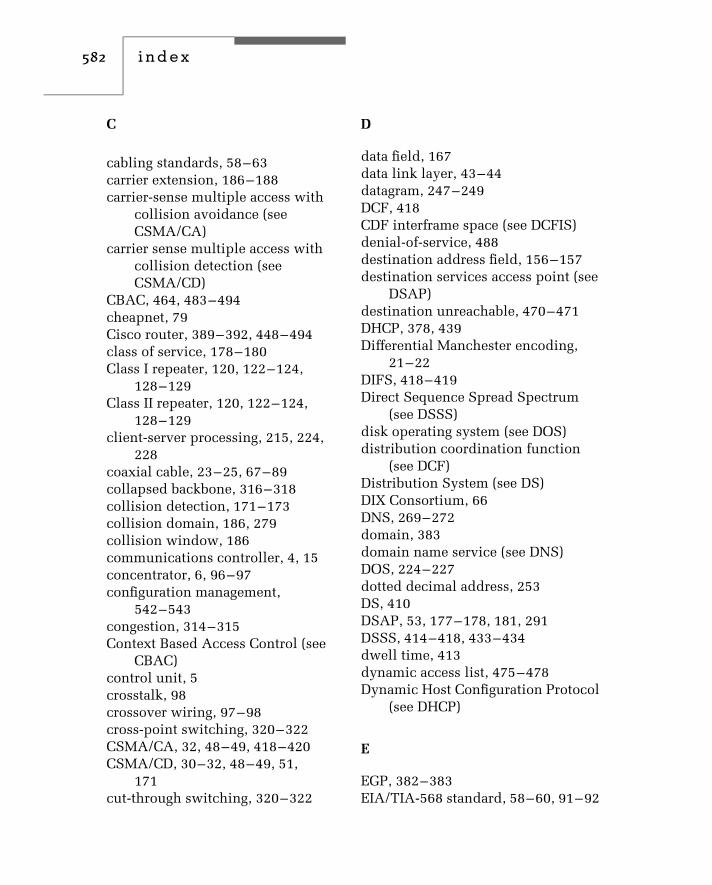
582 i n d e x
C
cabling standards, 58–63carrier extension, 186–188carrier-sense multiple access with
collision avoidance (seeCSMA/CA)
carrier sense multiple access withcollision detection (seeCSMA/CD)
CBAC, 464, 483–494cheapnet, 79Cisco router, 389–392, 448–494class of service, 178–180Class I repeater, 120, 122–124,
128–129Class II repeater, 120, 122–124,
128–129client-server processing, 215, 224,
228coaxial cable, 23–25, 67–89collapsed backbone, 316–318collision detection, 171–173collision domain, 186, 279collision window, 186communications controller, 4, 15concentrator, 6, 96–97configuration management,
542–543congestion, 314–315Context Based Access Control (see
CBAC)control unit, 5crosstalk, 98crossover wiring, 97–98cross-point switching, 320–322CSMA/CA, 32, 48–49, 418–420CSMA/CD, 30–32, 48–49, 51,
171cut-through switching, 320–322
D
data field, 167data link layer, 43–44datagram, 247–249DCF, 418CDF interframe space (see DCFIS)denial-of-service, 488destination address field, 156–157destination services access point (see
DSAP)destination unreachable, 470–471DHCP, 378, 439Differential Manchester encoding,
21–22DIFS, 418–419Direct Sequence Spread Spectrum
(see DSSS)disk operating system (see DOS)distribution coordination function
(see DCF)Distribution System (see DS)DIX Consortium, 66DNS, 269–272domain, 383domain name service (see DNS)DOS, 224–227dotted decimal address, 253DS, 410DSAP, 53, 177–178, 181, 291DSSS, 414–418, 433–434dwell time, 413dynamic access list, 475–478Dynamic Host Configuration Protocol
(see DHCP)
E
EGP, 382–383EIA/TIA-568 standard, 58–60, 91–92

index 583
EL FEXT, 62–63end-of-stream delimiter (see ESD)Equal Level Far End Crosstalk (see
EL FEXT)error rate, 10–11ESD, 184–185ESS, 410–411ESSID, 410–411estimating network traffic, 304–306,
308–312Ethernet Networks, 65–152Ethernet-SNAP, 92, 177–178,
181–182Ethernet switch, 127–128Ethernet traffic estimation, 308–312Ethernet Version, 1 66Ethernet Version, 2 66Ethernet-802.3 180–181EtherPeek, 559–564EtherVision, 163–165, 545–554EXEC session, 449–450extended access list, 462–465Extended Service Set (see ESS)Extended Service Set Identifier (see
ESSID)exterior domain routing protocol,
382–383Exterior Gateway Protocol (see
EGP)external commands, 225
F
Fast Ethernet, 44, 50, 55, 75,111–133, 184–185
fat pipe, 128, 339fault management, 543–544FCS, 53, 167–168
FDDI, 111, 119FHSS, 412–414, 432–433fiber adapter, 102fiber channel, 143–144fiber-optic cable, 25–29fiber optic repeater link (see FOIRL)file server, 214–218filtering, 199–202, 281, 339,
399–404firewall, 494–516flooding, 197–202, 281, 295flow control, 210FOIRL, 100–104forwarding, 199–202, 281, 339frame check sequence (see FCS)frame bursting, 188–189frame determination, 183–184frame operations, 154–190frequency shift keying (see FSK)frame translation, 204flow control, 339–342fragmentation, 210Frequency Hopping Spread
Spectrum (see FHSS)FSK, 19full-duplex, 100, 112–113, 221,
342–343
G
gateway, 213–216, 365Gigabit Ethernet, 55, 138–153,
185–189, 567–569gigabit media-independent interface
(see GMII)GMII, 44, 141, 150–151grounding, 82–83group address, 157

584 i n d e x
H
headend, 88–89header hub, 90hidden node, 420hub, 18, 93–96, 134–136, 194,
218–219hybrid switching, 324–325
I
IAB, 56–57IBM, 3270 Information Display
System, 3–7ICMP, 246, 249–252, 470IEEE, 37–39, 48–55, 159IEEE, 802.1Q Frame, 182–183,
350–351IEEE, 802.3x flow control,
341–342IEEE, 802.11 standard, 407–444IETF, 56–57IGRP, 393–394Industrial, Scientific and Medical
(see ISM)infrared, 412infrastructure network, 221–222,
409–411Institute of Electrical and Electronic
Engineers (see IEEE)intelligent hub, 219, 313–314interframe gap, 168, 195interior domain routing protocol,
381–382, 384–386Interior Gateway Routing Protocol
(see IGRP)intermediate hub, 90internal commands, 225
International TelecommunicationsUnion (see ITU)
Internet Activities Board (see IAB)Internet Control Message Protocol
(see ICMP)Internet Engineering Task Force (see
IETF)Internet Packet Exchange (see
IPX)Internet Protocol (see IP)Internet Standards, 55–57internetworking, 65interrepeater cable segment,
83–84intranet, 280IP, 45, 260–269IP addressing, 265–269IPX, 45, 227, 230–233, 371–372,
374–377ISDN, 109ISM, 408, 413ISO, 38–40ISO Reference Model, 41–48isochronous Ethernet (see
isoENET)isoENET, 51, 108–110ITU, 40
J
jabbering, 95, 343jam signal, 69–70, 171–172jitter, 72
K
Kruskal’s algorithm, 286–288

index 585
L
LAN switches, 312–364late collision, 98, 173–174latency, 321–324, 343–344layer, 2 switching, 391–356layer, 3-based vLAN, 356–357length field, 165–167link code word, 124–125link driver area, 235–236link integrity test, 92, 124link state protocol, 394–395link support area, 233–234link support layer (see LSL)listener, 29–30LLC, 44, 51, 176–180, 291locally administrated addressing,
157–158, 280logical connection, 43logical link control (see LLC)LSL, 232–233
M
MAC, 44, 52–53, 154, 169–176, 253MAC address, 52MAC-based vLAN, 352–355major network number, 391management information base (see
MIB)Manchester encoding, 21–22Manufacturing Automation Protocol
(see MAP)MAP, 49MAU, 69, 77–78, 83, 86–88Maximum Transmission Unit (see
MTU)MDI, 44
media access control (see MAC)medium attachment unit (see MAU)medium-dependent interface (see
MDI)medium-independent interface (see
MII)Metcalfe, Robert, 66MIB, 532–534MII, 114–115mirrored port, 344modulation, 19MTU, 263–264multicast, 158, 359multimode fiber, 105–106, 144–145multiplexer, 6multiport repeater, 96multi-tier network construction,
330–332
N
named access list, 472–474NAT, 437–439NCP, 230-NDIS, 239–243near-end crosstalk (see NEXT)NET command, 230–233NetBEUI, 227, 236–237NETBIOS, 225–226, 236, 377NET.CFG file, 233NetWare, 180–181, 228–236,
374–377NetWare Core Protocol (see NCP)network address translation (see
NAT)network concepts, 1–35network interface card (see NIC)network layer, 44–45

586 i n d e x
network segmentation, 315NEXT, 61–62NIC, 70–71, 77, 92–93, 129–133,
160–163Non-routable protocols, 372–373N-series connector, 70–72nslookup, 448Nway, 124–125
O
OFDM, 408, 417–418Open Shortest Path First (see OSPF)Open System Interconnection (see
OSI)optical loss budget, 106–107optical transceiver, 101orthogonal frequency division
multiplexing (see OFDM)OSI, 41, 46–47OSI Reference Model, 41–48OSPF, 397–398
P
parallel tasking, 574–575path cost, 288–289PC ACR, 63PCS, 44peer-to-peer processing, 224physical coding sublayer (see PCS)physical layer, 43physical medium attachment
sublayer (see PMA)physical medium dependent (see
PMD)physical topology, 285
Ping, 251–253, 448, 470plenums, 68plug and play, 282PMA, 44PMD, 54poll and select, 5populated segments, 73–74, 78port/address table, 280–282port-based switching, 325–326port numbers, 252, 255power management, 425power sum attenuation (see PC ACR)preamble, 53, 91–93, 195presentation layer, 45–46promiscuous mode of operation, 208protocol-based vLAN, 358–359protocol-dependent router, 374–377protocol-independent router,
377–381proxy services, 502–504PS NEXT, 61–62
Q
QoS, 109, 399–400Quality of Service (see QoS)
R
radio frequency modems, 87RAS, 216–217reconciliation layer, 44, 54–55, 141reflexive access list, 478–482regulation, 11remote access server (see RAS)remote batch transmission, 39Remote Monitoring (see RMON)

index 587
repeater, 71–74, 96, 192–195Request for Comment (see RFC)retiming, 72RFC, 56–57RG-58 C/U, 79RIF, 293–296RIP, 386–392ring structure, 16RMON, 535–541roaming, 411–412root bridge, 288root hub, 134root port, 289router, 205–210, 316–318, 265–405routing information field (see RIF)Routing Information Protocol (see
RIP)routing table, 368–370Routing Table Maintenance Protocol
(see RTMP)RTMP, 392rule-based vLAN, 359–360
S
SAP, 53, 176–177security, 447–529security management, 544segment-based switching, 326–327self-learning bridge, 280sequential bridging, 300–302Sequence Packet Exchange (see SPX)serial bridging, 300–302service advertising packet, 157service access point (see SAP)service primitives, 174–175, 180session layer, 45shielded twisted-pair (see STP)
Short Interframe Space (see SIFS)Shortest Path First (see SPF)SIFS, 418–419signal quality error (see SQE)silver satin wire, 98Simple Network management
Protocol (see SNMP)single mode fiber, 143slot, 172SNA, 372–373, 378–381SNMP, 455–456, 531–535source address field, 159–161source routing, 49, 292–297source routing transparent bridge,
297–299source services access point (see
SSAP)Spanning Tree Protocol, 283–291,
346–347SPF, 395–397SPX, 45SQE, 69–70SSAP, 53, 177, 181, 291SSD, 184–185ST connector, 106standard access list, 459–462standards, 37–63standards organizations, 37–63star structure, 16StarLAN, 89–90, 102start-of-stream delimiter (see SSD)store-and-forward switching,
322–324STP, 50, 58–59subnet-based vLAN, 357subnet mask, 268–269, 366–368subnetting, 267–269, 366–368switching hub, 219–221, 312–365System Network Architecture (see
SNA)

588 i n d e x
T
T1 circuit, 6–8talker, 29–30TCP, 45, 254–259TCP intercept, 483TCP/IP protocol suite, 244–277TFTP, 467–468thick Ethernet, 68, 70–72,
75–79thin Ethernet, 68, 71, 72–87thinnet, 79thinnet tap, 81time-based access list, 482–483time domain reflectometer, 543time-to-life (see TTL)token passing, 32–34Token-Ring, 49topology, 11–12, 14transceiver, 67–70, 77, 93–94transceiver cable, 69translating bridge, 200–201Transmission Control Protocol (see
TCP)Transmission System Model, 1
146–147Transmission System Model, 2
146–147transparent bridge, 199–200,
280–292transport layer, 45transport protocol, 373–374tree structure, 16trivial file transfer program (see
TFTP)TTL, 264tunneling, 373twisted-pair wire, 22type field, 164–165, 168type of service, 178–179
U
UDP, 45unicast address, 158unipolar non-return to zero signal,
21universal Ethernet transceiver,
81–82universally administrated
addressing, 157–158unshielded twisted-pair (see UTP)User Datagram Protocol (see UDP)UTP, 50, 58–59, 91, 259–260
V
vampire tap, 82vector distance protocol, 385–389virtual circuit, 247–249virtual LAN (see vLAN)virtual loadable modules, 236virtual private network (see VPN)virtual terminal (see vty)virus scanner, 517–528vLAN, 182–183, 347–360VPN, 376vty, 450–452
W
WAN, 2–8wait time, 172–173wander, 72WebXRay, 554–559WEP, 426, 442–445wide area network (see WAN)

index 589
Windows, 236–243, 272–277Wired Equivalent Privacy (see WEP)wireless bridge, 223–224, 407–445wireless router, 222–223wiring, 96–99
X
Xerox Wire, 66X.25 45, 214X.75 45
NUMERICS
1BASE-5 48, 89–9010BASE-2 68, 79–87, 103–10410BASE-5 48, 68, 75–79, 85–8710BASE-F, 100–101, 10410BASE-FB, 10710BASE-FP, 107–108
10BASE-FL, 104–10710BASE-T, 48, 91–10010BASE-T/FL converter, 10510BROAD-36 48, 87–89100BASE-FX, 50, 112, 120–124100BASE-T, 111100BASE-TX, 50, 110–111,
117–133, 184100BASE-T4 50, 111, 114–117100VG-AnyLAN, 50–51, 75,
133–1381000BASE-CX, 142, 1451000BASE-LX, 142–145, 1471000BASE-LH, 142, 144–1451000BASE-SX, 142, 1471000BASE-T, 1423Com Corporation, 131–1324B/5B coding, 109, 119, 1215-4-3 rule, 73–74, 78, 998B6T coding, 117802 committees, 48–50802.3 networks, 74–153


