Embed Size (px)
Citation preview
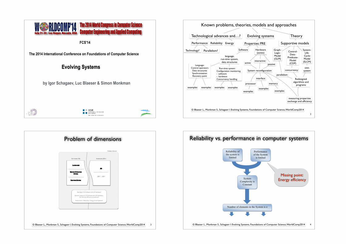
FCS'14 !The 2014 International Conference on Foundations of Computer Science
!
Evolving Systems!
!by Igor Schagaev, Luc Blaeser & Simon Monkman
!!!
!!
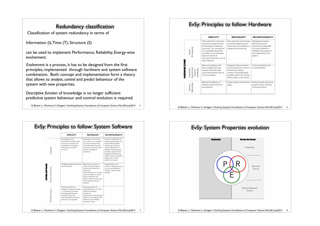
Known problems, theories, models and approaches
Technological advances and…? Evolving systems
Parallelism?
Energy Properties: PRE Performance
language, run-time system, data structures
System- Life-
Cycle- Model (SLCM)
Reliability
Language: Control operators
Data structures Synchronisation Recovery point
Run-time system: Configuration monitoring - software - hardware Concurrency handling
Technology? Hardware (zones)
Software
Theory
Supportive models
Control- Data-
Predicate- Model (CDP)
Graph- Logic- Model (GLM)
activeinteractive
passiveuser,
systemSystem reconfiguration concurrency
parallelism
processor memory
interface Redesigned algorithms and
programsexamples examples examples examples
examplesexamples
examples
measuring properties exchange and efficiency
© Blaeser L., Monkman S., Schagaev I. Evolving Systems, Foundations of Computer Science, WorldComp2014
2
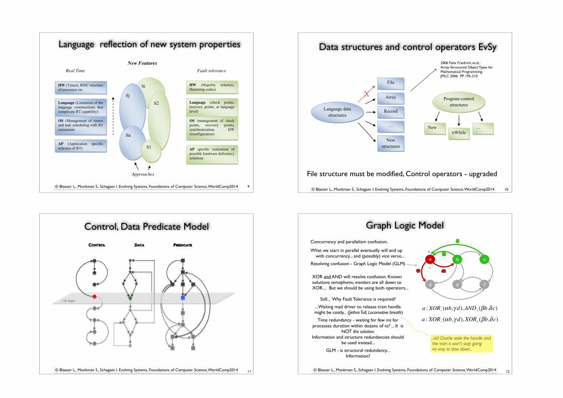
Problem of dimensions
3
3D ? … nD ?
2D
Problem Domain
LANGUAGES
SERVICE OPERATING
SYSTEM
RUN-TIME SYSTEM
SOFTWARE (1D) HARDWARE (2D+)
Marriage of 1D Software with 2D Hardware?
Dynamic support of 1D Software with 2D Hardware – Can there be efficient co-existence?
Performance-, Reliability-, Energy- Smart Systems?
© Blaeser L., Monkman S., Schagaev I. Evolving Systems, Foundations of Computer Science, WorldComp2014
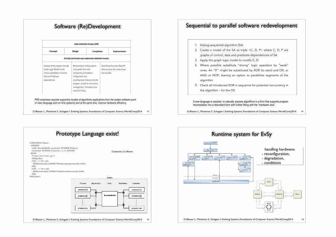
Reliability vs. performance in computer systems
4
Missing point: Energy efficiency
3. FAULT TOLERANCE: THEORY AND CONCEPTS
Reliability of the system is
limited
Performance of the System
is limited
Number of elements in the System is n
System Complexity is
Constant
Figure 3.3: Maximum reliability of a RT FT system
The usefulness of the predictions depend here on timing, relevance and practicality.
Structural analysis of variants how to implement system software support of hard-
ware deficiencies uses the classification of redundancy types and schemes of its appli-
cation to achieve fault tolerance. The classification developed here is a refinement of
many previous results from [147, 70, 9] and is, in fact, a further development of [63, 1].
The two top boxes of Figure 3.4 present the way we think, while the lower box
presents the way we implement fault tolerance. In general, three di↵erent redundancy
types exist, namely structural (S), informational (I) and time (T ) redundancy. Every
concrete implementation of system redundancy uses at least one of these three redun-
dancy types, often more than one and can be implemented in pure hardware (HW ()),
pure software (SW ()) or a combination of both (HW (), SW ()). As an example, soft-
ware based information redundancy is abbreviated as SW (I). We use additional quan-
tifiers together with the redundancy type to further specify the used redundancy as
shown in Table 3.1.
Please note that the current notation does not include the implementation level.
HW (2S) just indicates duplication, but not whether the whole system is duplicated or
just parts of it, such as for example duplicated memory.
18
© Blaeser L., Monkman S., Schagaev I. Evolving Systems, Foundations of Computer Science, WorldComp2014
Redundancy classification
5
Classification of system redundancy in terms of !Information (I), Time (T), Structure (S) !can be used to implement Performance, Reliability, Energy-wise evolvement. !! Evolvement is a process, it has to be designed from the first principles, implemented through hardware and system software combination. Both: concept and implementation form a theory that allows to analyse, control and predict behaviour of the system with new properties. !!!Descriptive function of knowledge is no longer sufficient: predictive system behaviour and control evolution is required.
© Blaeser L., Monkman S., Schagaev I. Evolving Systems, Foundations of Computer Science, WorldComp2014
EvSy: Principles to follow: Hardware
6© Blaeser L., Monkman S., Schagaev I. Evolving Systems, Foundations of Computer Science, WorldComp2014
! SIMPLICITY REDUNDANCY RECONFIGURABILITY!
Act
ive
(Pro
cess
ors)
Only essential for instruction execution hardware should be developed, duplicated instruction “for convenience” or compatibility should be excluded; no not necessary back-sire actions of instruction execution, such as signs, flags etc.!
Extra elements and schemes should be added either for improvement of reliability or energy-wise functioning.
Designed processing element should be internally reconfigurable (not used hardware is disabled) and support of reconfigurability of the system
Inte
ract
ive
(Inte
rnal
and
Ex
tern
al
Inte
rfac
es)
Minimum hardware with when possible state-less designs should be used, using asynchronous logic as much as possible.
Designed interconnections must be identical in terms of functioning, making maximum reconfigurability possible, able to be used as direct access in and onward.
Control of physical and virtual addresses.
Pass
ive
(Mem
orie
s) Reduced complexity of
address schemes (internal and external).
Virtual memory (of the same type).
Ability to switch data ands program areas, hierarchy of recovery points.
Lang
uag
e
At language level - cancelling of complex data structures; limitation and simplification of program descriptions and code structure
Generation of more than one code to run a program for various requirements: P.R.E Automatic hierarchy formation of recovery point (also for reliability of operation)
Semantic modification of program (graph-logic and control data predicate models, see further) to reduce dependencies between code segments and data; support at the language and operating systems -service operating system and run-time system), processes.
Mon
itor
of p
roce
sses
Simplified support of process synchronisation;
Reducing of number of states in synchronisation systems and hierarchy of processes Implementation of universal loop with ability to control state of hardware and system software at the same time, reducing resource wasting.
Implementation and control of software during run-time and hardware - making “integrity map” possible.
Relia
bili
ty s
upp
ort
Recovery points of a program, modules and tasks - to implement hot swap (reconfigurability) when needed. Saving only essential data for concrete execution of a program.
Reducing amount of supportive data in run-time system for program monitoring Introducing of reserved data blocks to run hardware with deficiency (for reliability purpose of view)
HA
RD
WA
RE
ZO
NE
S SY
STE
M S
OFT
WA
RE
EvSy: Principles to follow: System Software
7© Blaeser L., Monkman S., Schagaev I. Evolving Systems, Foundations of Computer Science, WorldComp2014
! SIMPLICITY REDUNDANCY RECONFIGURABILITY!
Act
ive
(Pro
cess
ors)
Only essential for instruction execution hardware should be developed, duplicated instruction “for convenience” or compatibility should be excluded; no not necessary back-sire actions of instruction execution, such as signs, flags etc.!
Extra elements and schemes should be added either for improvement of reliability or energy-wise functioning.
Designed processing element should be internally reconfigurable (not used hardware is disabled) and support of reconfigurability of the system
Inte
ract
ive
(Inte
rnal
and
Ex
tern
al
Inte
rfac
es)
Minimum hardware with when possible state-less designs should be used, using asynchronous logic as much as possible.
Designed interconnections must be identical in terms of functioning, making maximum reconfigurability possible, able to be used as direct access in and onward.
Control of physical and virtual addresses.
Pass
ive
(Mem
orie
s) Reduced complexity of
address schemes (internal and external).
Virtual memory (of the same type).
Ability to switch data ands program areas, hierarchy of recovery points.
Lang
uag
e
At language level - cancelling of complex data structures; limitation and simplification of program descriptions and code structure
Generation of more than one code to run a program for various requirements: P.R.E Automatic hierarchy formation of recovery point (also for reliability of operation)
Semantic modification of program (graph-logic and control data predicate models, see further) to reduce dependencies between code segments and data; support at the language and operating systems -service operating system and run-time system), processes.
Mon
itor
of p
roce
sses
Simplified support of process synchronisation;
Reducing of number of states in synchronisation systems and hierarchy of processes Implementation of universal loop with ability to control state of hardware and system software at the same time, reducing resource wasting.
Implementation and control of software during run-time and hardware - making “integrity map” possible.
Relia
bili
ty s
upp
ort
Recovery points of a program, modules and tasks - to implement hot swap (reconfigurability) when needed. Saving only essential data for concrete execution of a program.
Reducing amount of supportive data in run-time system for program monitoring Introducing of reserved data blocks to run hardware with deficiency (for reliability purpose of view)
HA
RD
WA
RE
ZO
NE
S SY
STE
M S
OFT
WA
RE
EvSy: System Properties evolution
8© Blaeser L., Monkman S., Schagaev I. Evolving Systems, Foundations of Computer Science, WorldComp2014
!
LANGUAGES
RUN-TIME
SYSTEM
SERVICE OPERATING
SYSTEM
R P
E
SYSTEM SOFTWARE HARDWARE
Language reflection of new system properties
9
New Features
HW (Timers, RISC structure of processor etc
Language (Limitation of the language constructions that complicate RT capability)
OS (Management of timers and task scheduling with RT constraints
AP (Application specific schemes of RT)
HW (Majority schemes, Hamming codes)
Language (check points, recovery points, at language level)
OS (management of check points, recovery points, synchronization, HW reconfiguration)
AP specific realization of possible hardware deficiency solutions
Real Time Fault tolerance
Approaches
Si
Sj
S2
Sn
S1
Figure 6.1: System representation and implementation hierarchy
the supportive means by the operating system. Assume that a program requires RT
access to program data. To guarantee the required real time constraints it is important
to exclude file structures, as these do in general not allow direct and equal (in time)
access to the data. Instead, simpler data structures with guaranteed by design equality
to access each data element or record should be introduced.
Clearly, RT as new feature requires modification of almost all elements in Figure 6.1.
RT and FT are synthetic, not elementary feature of computer systems, and possible
implementations can be located at di↵erent layers in system hierarchy.
Some well-known solutions exist for achieving RT in a computing system, such
as limiting the use of data constructs, deliberate introduction of time-limit program
control structures, exclusion of complex instructions from the processor architecture,
limitation of pipelining, strong extension of timer schemes, etc.
The ellipses in the middle of Figure 6.1 represent possible implementations of new
features. As a general rule, the top down principle should be applied, i.e. every new
feature should be implemented at the top level of the system hierarchy if possible. This
rule does also imply that implementations of new features like S1, which is implemented
on the application level, are excluded from this research. Instead, we concentrate on
new features implemented at the top layers of the presented hierarchy, assuming that
the resulting dynamic system behaviour will be under full control.
67
© Blaeser L., Monkman S., Schagaev I. Evolving Systems, Foundations of Computer Science, WorldComp2014
Data structures and control operators EvSy
10
File structure must be modified, Control operators - upgraded
2006 Felix Friedrich, et.al.: Array-Structured Object Types for Mathematical Programming. JMLC 2006: PP 195-210
6. SYSTEM SOFTWARE FOR HARDWARE DEFICIENCY:FUNCTION AND FEATURES
X
Language data structures
Program control structures
nWhile New …
File
Array
Record
…
New structures
Figure 6.2: Modification of data structure limited by application domain
Let’s take language features as an example. A programming language can be de-
scribed by means of control structures, presentation of data types and the realisation
of sequential and conditional expressions. For example, typical data structures are:
arrays, strings, files, records (Figure 6.2).
If hard realtime is required file data structures should be excluded from the set
of possible data structures in RT applications because files do not guarantee equal
access time over all files and all file data. New features might also be developed. For
RT applications, the language control structures might also be modified to provide
a higher level of control and timing conformance during program execution. Also, if
possible, control structures should be simplified as much as possible due to the strict
timing requirements and as small as possible overheads. One promising feature would
be the nWhile [136].
FT as a new feature of embedded systems, implemented on the level of system
software should be analysed in some details. First, let us consider fault tolerance as a
sequence of steps as introduced by GAFT in Section 4.
When we defined FT as GAFT it became possible to investigate how system software
should be involved to realize this algorithm. Then, all required features and mechanisms
of system software to support fault tolerance of embedded systems can be derived from
GAFT.
There are several processes and functions in the system software to provide fault
tolerance:
Research in the area of program recovery after a hardware fault has occurred is
known for 40 years. Google search shows millions of related links, including some even
68
© Blaeser L., Monkman S., Schagaev I. Evolving Systems, Foundations of Computer Science, WorldComp2014
Control, Data Predicate Model
11
!
i-th layer
CONTROL PREDICATE DATA
© Blaeser L., Monkman S., Schagaev I. Evolving Systems, Foundations of Computer Science, WorldComp2014
Graph Logic Model
12© Blaeser L., Monkman S., Schagaev I. Evolving Systems, Foundations of Computer Science, WorldComp2014
18
...old Charlie stole the handle and the train it won't stop going no way to slow down...
Concurrency and parallelism confusion;
What we start in parallel eventually will end up with concurrency... and (possibly) vice verso...
Resolving confusion - Graph Logic Model (GLM)
Fig. 2. Control-, Data-, Predicate Model
generating ‘snapshots’ of the previous hardware states as well as the flexibility of program segmentation and allocation.
Regretfully, in the vast majority of architectures, the functions of data access and data processing are tightly mixed. In a typical processor, such as the ARM, Intel and SPARC, the arithmetic and logic unit (ALU), or even several of them, as well as shifters, registers, internal cache, special registers and pipeline sequencers etc. are active during the execution of each instruction, sometimes with several data passes within a single instruction. Thus, the complexity of monitoring and feeding them with data even without assuming possible faults becomes enormous: 75% of the die size is occupied by translation look ahead buffers, caches, synchronization logic and pipelining. However, none of them is required from the programming language operator point of view.
The number of elements (nodes) in each of the CDP graphs is defined by the architecture. Any current condition of architecture related to the operator or instruction representation (three nodes within the same layer of Fig. 2) requires hardware state checking for parallelism or reliability to maximize the first and limit fault propagation for the second
The complexity and the implementation cost of parallelization or fault tolerance are directly related to the amount of the resulting modifications of the hardware and program states. CDP shows that when P (predicate) is used only for the selection of the program flow, a special operator and instruction can be defined to generate the current value of P and store the result in a register. Such modifications of the instruction set restrict changes of predicates. CDP simplification eases the implementation at the hardware and system software level. For the implementation of parallelization at the level of the instruction set, the design objectives will be:
- Minimization of the state space that needs to be saved before each instruction’s execution
- Implementation of “as simple as possible” logic to form predicates
- Mapping of language operators as close as possible to the modified instruction set of the processor
Hardware instructions represent data, control and predicate
dependencies of language operators at execution time. Thus an analysis of CDP for language and hardware will clarify their interaction consistently and exclude “improvements” that
Fig. 3. Graph Logic Model
drive to mutual loss. Studying the CDP scheme also enables checking of potential program parallelism in all three graph dependencies. Surprisingly, this is not the whole picture. As a further development of parallelization and concurrency reduction we introduce the graph–logic-model (GLM).
Every meta-program structure might be described using GLM (Graph Logic Model) that provides a scheme to redevelop existing programs into their maximum parallel and minimum concurrent form, limited only by available hardware resources. An indicative example how GLM and GLL work together using a program control graph is presented in Fig. 3.
Note that GLM might be applied for any of graph of the CDP model. GLM uses logical operators from the set {AND, OR, XOR} for every program or hardware scheme that it describes. These operators are allocated for the input and output of each vertex. A vertex might be an operator, instruction or state. Vertex a in the example of Fig. 3 may be described thus as:
a: OR-(!b, "d), AND+(#b, $c) (1)
“-“ stands for every logical operator of an output link and
“+” for every input link, while !, ", #, $ are weights or priorities assigned for the link.
Until now research in parallelism was mostly targeted at finding parallel branches of programs and independent data elements. However, expecting pure parallelism is hardly feasible: what is initiated as parallel segments ends up ultimately in concurrent mode, competing for a resource such as a socket, printer, data concentrator, etc. The rare exception, such as graphic processors with high numbers of SIMD like processors just proves the rule. The simple notation of Fig. 3 can be used as a first step in the formation of the graph logic language to describe program structures and hardware structures consistently in terms of co-existing concurrency and parallelism.
GLM explicitly separates parallel and concurrent elements in the system description by introducing logic operators in the program graph for incoming and outgoing ends of edges. Thus, the application of the logic operator XOR (exclusive OR) on an input or output of an edge defines ALL possible concurrencies in the program graphs. In turn, all possible parallelism in the control graph are defined by finding all outgoing or incoming edges explicitly described by the AND
!
!
a b
d
c
e f
"
#
$
+
-
a :XOR− (αb,γ d),XOR+ (βb,δc)
a :XOR− (αb,γ d),AND+ (βb,δc)
XOR and AND will resolve confusion. Known solutions semaphores, monitors are all down to XOR.... But we should be using both operators...
Still... Why Fault Tolerance is required?
...Waiting mad driver to release train handle might be costly... (Jethro Tull, Locomotive breath)
Time redundancy - waiting for few ms for processes duration within dozens of ns? ... It is
NOT the solution. Information and structure redundancies should
be used instead...
GLM - is structural redundancy...Information?
Saturday, 26 October 13
Software (Re)Development
13
Computers 2014, 3 10
Thus, we might explicitly seek to separate “what is good for the user from what is good for the system and hardware” and, where possible, spread these requirements through the life cycle of software and system development, as Table 3 illustrates.
Table 3. Phases of software development
The separation of concerns and goals of PRE-smartness requires supportive models of algorithmic
applications from the system software point of view (language and run time systems) and at the same time, improve hardware efficiency. Two models we propose for this are called Control Data Predicate (CDP) and Graph Logic Model (GLM).
5. Supportive models
5.1 Control Data Predicate (CPD) model
Within CDP model each operator in a program can be defined in terms of modifications of three connected graphs: Control (C), Data (D) and Predicates (P), illustrated in Figure 3.
The Control graph presents a sequence of instructions for assembler or processor, or operators for language. Data dependencies related to each operator and data that might be modified along program execution are illustrated by the Data graph. Finally, a graph of Predicates defines the change of conditions inside hardware and program to enable branching. Thus, every step of program execution is described and defined by a change in three graphs.
While the program operators define a number of elements (nodes) in each graph, the volume of the resulting predicates, state registers, processor and Program Status Words (PSW), physically represented in the hardware by so-called processor status registers, contributes to the “width” of each layer of these graphs.
USER ORIENTED PHASES (UW)
Concept Design Compilation Implementation
SYSTEM SOFTWARE AND HARDWARE ORIENTED PHASES
Analysis of the program through
Graph Logic Model to find
intrinsic parallelism in Control,
Data and Predicate
dependencies.
Recompilation of the program
into parallel form with
introduction of hardware
configuration and
reconfiguration features into the
program, as well as concurrency
management – formation of an
execution string.
Dual String Execution (New RT
data structure that unites arrays
and records).
PRE-smartness requires supportive models of algorithmic applications from the system software point of view (language and run time systems) and at the same time, improve hardware efficiency.
© Blaeser L., Monkman S., Schagaev I. Evolving Systems, Foundations of Computer Science, WorldComp2014
Sequential to parallel software redevelopment
14© Blaeser L., Monkman S., Schagaev I. Evolving Systems, Foundations of Computer Science, WorldComp2014
Computers 2014, 3 14
The answer to these questions is a part of the design challenge for any evolving system. Having a correct program, CDP and GLM can then be applied to extract the parallel segments and data paths and help in reducing concurrency.
This reversed programming gives us a chance to play with the software and monitor system software redundancy, (deliberately introduced at the recompilation phase) and hardware redundancy (introduced at the design phase) on the fly. It also enables to use reconfigurability of the system for Performance, Reliability, or Energy-smart functioning when it is necessary.
Figure 5 introduces the use of CDP and GLM for program parallelization. There is no doubt that we have to start from correct sequential program. The proposed sequence clearly separates properties required at the program-writing phase from the properties required during execution, as the latter are dependent on the hardware resources that are available and may change during execution. In this way, hardware features (that might be dynamically adapted during run-time) become represented in the program logic.
Figure 5. Sequence of steps to make sequential algorithm parallel
A new language is needed to naturally express algorithms in a form that supports program
recompilation into a redundant form fitting with the “hardware view”. This does not mean that other programming paradigms such as structured, or OO are no longer useful. It means, though, that they have their limits and mostly serve user convenience and interfacing. The newly proposed paradigm serves to improve performance of the end product. This is achieved with the design of a new reconfigurable architecture, a system software and the dynamic transformation of existing software into a form that is efficiently executable by adaptive hardware: Evolving Reconfigurable Architecture (ERA), or more generally, Evolving System (ES).
Interestingly, the algorithm of parallelization might be applied for all three dependency graphs - Control, Data and Predicate - and therefore deduce the maximal parallel form. The availability of hardware serves as the termination condition for this algorithm.
1. Debug sequential algorithm (SA)
2. Create a model of the SA as triple <C, D, P> where C, D, P are
graphs of control, data and predicate dependencies of SA
3. Apply the graph logic model to modify C, D
4. Where possible substitute “strong” logic operators by “weak”
ones. An “IF” might be substituted by XOR (to start) and OR, or
AND or NOP, leaving an option to parallelize segments of the
algorithm
5. Check all introduced XOR in sequence for potential concurrency in
the algorithm – for the OS
A new language is required to naturally express algorithms in a form that supports program recompilation into a redundant form with further fitting with the “hardware view”.
Prototype Language exist!
15© Blaeser L., Monkman S., Schagaev I. Evolving Systems, Foundations of Computer Science, WorldComp2014
Computers 2014, 3 16
Figure 6. Describing hierarchical component structures
Due to the strict encapsulation, the components and can be easily mapped to various hardware architectures. Inherently, it enables parallelism (N components may be scheduled on up to N processors), as well as redundancy (the same components may be executed as multiple replicated instances). In subsequent work, a prototype compiler and run-time system for evolving systems has already been developed.
Direct support for reconfigurability and recoverability of program structures at the language level makes reconfiguration of system possible in case of hardware degradation due to faults, or task special requirements of system power-saving operation, or on the opposite, boosting task by using maximum hardware resources for completion of a task with required time limits.
For hardware fault tolerance, where malfunctions outweigh permanent faults, system software at the language level should include recovery points for the program at various levels of program presentation: procedure, module, and task. A detailed description of language support of hardware fault tolerance using recovery points is presented in [22]. Note here that the recovery point scheme will be embedded in the language and oriented on the programs and data structure. This reduces the overhead for recovery after malfunctions and eases the impact of possible permanent faults.
Figure 7. Communication-based component
INTERFACE DataAcceptor; [ IN Element (x: INTEGER)] IN Finish END DataAcceptor;
COMPONENT System; VARIABLE buffer: BoundedBuffer; producer[i: INTEGER]: Producer; consumer[i: INTEGER]: Consumer; i, n, m: INTEGER; BEGIN (* read n and m from user *) NEW(buffer); FOR i := 1 TO n DO NEW(producer[i]); CONNECT(DataAcceptor(producer[i]), buffer) END; FOR i := 1 TO m DO NEW(consumer[i]); CONNECT(DataSource(consumer[i], buffer) END; END System;
Computers 2014, 3 17
6.2 Active Reconfigurable Run Time System (ARRUS)
The run-time system, ARRUS, should also be involved in supporting real-time processing, as well as real-time reconfiguration of the underlying hardware elements and the respective network topology, including:
− Flexible dynamic hardware resource management; − Software reconfiguration to adapt to changes in hardware states and system conditions; − Management of hardware/software interactions in the presence of hardware faults; − Hardware state monitoring and support of graceful degradation using testing and recovery
procedures and reconfiguration management. To match the required features, such as reconfigurability, parallelization, real-time, resilience to
hardware degradation, and distributed control processing, the ARRUS itself is built in a strict hierarchical manner, as it is illustrated in Figure 8.
The lowest level module has no dependencies at all and consists of the main system monitor which is responsible for the coordination of all activities, such as the initialization of reconfiguration entities, timer services (not shown), interrupt handling and all the remaining depicted functions.
ARRUS also provides all the standard functions of a run-time system, such as memory management, which are well known and explained in literature [34], [35]. These features are omitted in Figure 8 to keep the diagram understandable.
In a standard control loop system, it is up to the programmer and the applications to diagnose faults and react appropriately. In ARRUS, however, this is not the responsibility of the application, but of the run-time system.
Thus, ARRUS is responsible for diagnosing faults (software failure, malfunction, permanent fault, etc.) and notifying the appropriate software and hardware monitoring services of any required changes.
Composita, Luc Blaeser
Runtime system for EvSy
16
handling hardware: - reconfiguration, - degradation, - conditions
12. PROPOSED RUNTIME SYSTEM STRUCTURE
FT interrupt handler
Main monitor
Reconfiguration monitor
Hardware monitor FT Scheduler Module Loader System
diagnostics
Fault Log
Testing procedures
Runtime
User space
Resource management
Applications
Figure 12.1: Proposed Runtime System Structure
In case of a permanent fault, this module reconfigures the hardware to a new
fault free state and informs the reconfiguration monitor about the new hardware
topology.
FT Scheduler The FT scheduler is responsible for scheduling tasks and tests as de-
scribed in section 7.2. It manages all activities and is responsible for scheduling
hardware tests according to the SSD policy.
Module loader The module loader is optional and is responsible for allocating and
linking the modules at runtime. For a production system, depending on the
linking strategy, the module loader might not be necessary.
System Diagnostics This module manages all hardware and software checks that are
currently present in the system and interacts with the FT scheduler. In case of a
fault this module is responsible for selecting the appropriate tests for diagnosing
the fault (software failure, malfunction, permanent fault, etc) and notifies the
software and hardware monitoring services of any required changes.
Testing Procedure The runtime system itself also provides a built in testing mech-
anism to ensure the integrity of the runtime itself and manages also the tests of
the other
Fault Log All faults are logged in the fault log for traceability and to support the
198
© Blaeser L., Monkman S., Schagaev I. Evolving Systems, Foundations of Computer Science, WorldComp2014
!!
ACTIVE
MASTER
SLAVE
STAND-BY
SUSPECTED
FAULTY
Reconfigurability of hardware
17
How to put all this together?
199$
By$following$these$principles$the$processes$of$design$and$development$of$a$new$architecture$can$be$defined.$$
$Figure+631.+System+zones+from+a+information+processing+point+of+
view+
Figure$6?1$ shows$ a$ computer$ system$as$ three$ semantically$ different$ (from$ the$point$ of$ view$ of$ information$ processing/transformation)$ elements.$ The$principles$mentioned$above$might$be$applied$at$the$level$of$each$element,$which$will$help$into$designing$a$more$efficient$computer$system.$$
$Figure+632.+Information+processing+in+ERA+
213$
• External$elements$responsible$for$exercising$GAFT$and$making$decision$on$
configuration$/$reconfiguration$if$necessary$
• Internal$elements$capable$of$initiating$the$required$sequence.$$$
Indeed,$ in$ a$ regular$ computing$ system$when$ there$are$ faults$ in$ the$processing$
logic,$to$expect$that$the$processor$is$able$to$perform$self?healing$and$then$control$
and$monitor$configuration$of$the$rest$of$the$system$is$unrealistic.$We$propose$a$
possible$solution$as$described$below.$
$
Figure+637.+Processor+structure+with+“separation+of+concerns”+
Figure$6?7$shows$conceptually$the$ERRIC’s$active$zone$divided$by$two$AU$and$LU$
elements.$
To$ be$ able$ to$ trust$ information$ regarding$ the$ status$ of$ an$ element,$ every$
checking$signal$about$the$condition$of$registers$(not$shown),$memory$units,$AU$
and$ LU$ as$ well$ as$ control$ unit$ should$ be$ aggregated$ in$ syndrome.$ The$
implementation$scheme$of$fault$tolerance$separates$the$passive$zone$and$active$
zone$ of$ the$ proposed$ architecture.$ A$ clear$ separation$ of$ the$ functions$ of$
© Blaeser L., Monkman S., Schagaev I. Evolving Systems, Foundations of Computer Science, WorldComp2014
Reconfigurability of hardware support: T-logic scheme
18
for single computer for multiprocessor system
Active Zone
ERRIC
Passive Zone
RAM RAM RAM
Memory used by ERRIC
Idle memory
T-logic ERA interconnector
AR
CH
ITEC
TUR
E B
US
- HW element should “switch itself”, “be switched on” - for PRE purposes under control of Run-time system
FP7-ICT-2013-4 PRESSA
© PRESSA consortium 2012 28
Figure 9 Indicative PRESSA configuration on wafer
FP7- ICT-2013-10 PRESSA
Proposal Part B: Page 22 of 59
Figure 7 Indicative reconfigurable architecture of PRESSA
ERRIC
MEMORY
ERRIC
MEMORY
ERRIC
MEMORY
ERRIC
MEMORY
ERRIC
MEMORY
ERRIC
MEMORY
ERRIC
MEMORY
ERRIC
MEMORY
ERRIC
MEMORY
ERRIC
MEMORY
ERRIC
MEMORY
ERRIC
MEMORY
IOE
IOE
IOE
IOE
IOE
IOE
IOE IOE IOE IOE IOE IOE
IOE IOE IOE IOE IOE IOE
IOE
IOE
IOE
IOE
IOE
IOE
© Blaeser L., Monkman S., Schagaev I. Evolving Systems, Foundations of Computer Science, WorldComp2014
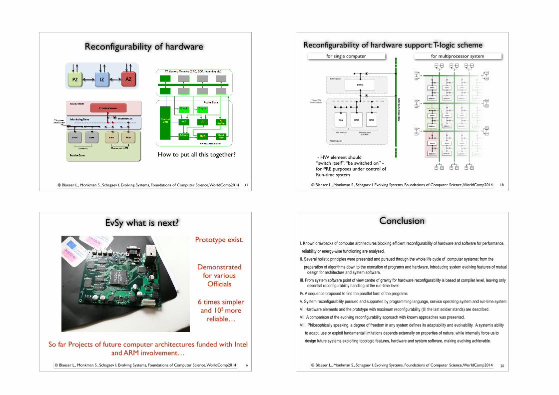
EvSy what is next?
19
Prototype exist.
Demonstrated for various
Officials
So far Projects of future computer architectures funded with Intel and ARM involvement…
6 times simpler and 105 more
reliable…
© Blaeser L., Monkman S., Schagaev I. Evolving Systems, Foundations of Computer Science, WorldComp2014
Conclusion
20
I. Known drawbacks of computer architectures blocking efficient reconfigurability of hardware and software for performance, reliability or energy-wise functioning are analysed. II. Several holistic principles were presented and pursued through the whole life cycle of computer systems: from the preparation of algorithms down to the execution of programs and hardware, introducing system evolving features of mutual
design for architecture and system software. III. From system software point of view centre of gravity for hardware reconfigurability is based at compiler level, leaving only
essential reconfigurability handling at the run-time level. IV. A sequence proposed to find the parallel form of the programs V. System reconfigurability pursued and supported by programming language, service operating system and run-time system VI. Hardware elements and the prototype with maximum reconfigurability (till the last soldier stands) are described. VII. A comparison of the evolving reconfigurability approach with known approaches was presented. VIII. Philosophically speaking, a degree of freedom in any system defines its adaptability and evolvability. A system’s ability to adapt, use or exploit fundamental limitations depends externally on properties of nature, while internally force us to design future systems exploiting topologic features, hardware and system software, making evolving achievable.
© Blaeser L., Monkman S., Schagaev I. Evolving Systems, Foundations of Computer Science, WorldComp2014
Thanks for…
21
- Discussions, joint efforts: T Kaegi, S Monkman, B Kirk - Discussions on redundancy: J C Laprie ( late 80’s ) - Discussions on reliability vs. FT: S Birolini (2005-10) - Discussions on GLM: Felix Friedrich - Pictures: Simon Monkman - Publication support: Chong Chen (Chinese version) - Publication support: Yurzin Bogdanov (Russian version)
Book: T Kaegi, I Schagaev System Software Support of Hardware Efficiency, ITACS Ltd 2013, UK, http://www.it-acs.co.uk/book.html Papers (1983-2014): https://londonmet.academia.edu/IgorSchagaev
© Blaeser L., Monkman S., Schagaev I. Evolving Systems, Foundations of Computer Science, WorldComp2014
Material used:
![Ana DUMITRAN, Zugravul Simon Bălgradeanul la Sebeş [Painter Simon Bălgradeanul from Sebeş]](https://img.pdfslide.net/doc/110x75/63152a3585333559270d03dd/ana-dumitran-zugravul-simon-balgradeanul-la-sebes-painter-simon-balgradeanul.jpg)


