Embed Size (px)
Citation preview
www.elsevier.com/locate/compstruct
Composite Structures 79 (2007) 467–480
Exact stiffness matrix of mono-symmetric composite I-beamswith arbitrary lamination
Dong Ku Shin a, Nam-Il Kim b, Moon-Young Kim c,*
a Department of Civil and Environmental Engineering, Myongji University, San 38-2, Nam-Dong, Yongin, Kyonggi-Do 449-728, Republic of Koreab Department of Civil and Environmental Engineering, University of Maryland, College Park, MD 20742, USA
c Department of Civil and Environmental Engineering, Sungkyunkwan University, Cheoncheon-Dong, Jangan-Ku, Suwon 440-746, Republic of Korea
Available online 20 March 2006
Abstract
The exact stiffness matrix, based on the simultaneous solution of the ordinary differential equations, for the static analysis of mono-symmetric arbitrarily laminated composite I-beams is presented herein. For this, a general thin-walled composite beam theory with arbi-trary lamination including torsional warping is developed by introducing Vlasov’s assumption. The equilibrium equations and force–deformation relations are derived from energy principles. The explicit expressions for displacement parameters are then derived usingthe displacement state vector consisting of 14 displacement parameters, and the exact stiffness matrix is determined using the force–defor-mation relations. In addition, the analytical solutions for symmetrically laminated composite beams with various boundary conditionsare derived as a special case. Finally, a finite element procedure based on Hermitian interpolation polynomial is developed. To demon-strate the validity and the accuracy of this study, the numerical solutions are presented and compared with the analytical solutions andthe finite element results using the Hermitian beam elements and ABAQUS’s shell element.� 2006 Published by Elsevier Ltd.
Keywords: Thin-walled composite beam; Exact stiffness matrix; Non-symmetric lamination
1. Introduction
Structural components made of anisotropic materialsare ideal for many structural applications because of thehigh strength-to-weight and stiffness-to-weight ratios andtheir ability to be tailored to meet the design requirementsof stiffness and strength. Thin-walled composite beamswith open cross-sections are widely used in civil, mechani-cal and aerospace engineering applications. These beamsmight be subjected to bending types of loading when usedin above applications. Therefore, it becomes important toevaluate exactly their deformation responses under thesetypes of loadings. Initial work on these types of problemsfor open profile sections has been done by Bauld and Tzeng[1]. They extended the Vlasov’s theory [2] of isotropic mate-
0263-8223/$ - see front matter � 2006 Published by Elsevier Ltd.
doi:10.1016/j.compstruct.2006.02.005
* Corresponding author. Tel.: +82 31 290 7514; fax: +82 31 290 7548.E-mail address: [email protected] (M.-Y. Kim).
rial to laminated fiber reinforced composite materials. Wuand Sun [3] developed a simplified theory for compositethin-walled beams. Under more general assumptions thanthose of Vlasov, the equilibrium equations consisted ofseven ordinary differential equations including the effectsof torsional warping and transverse shear deformation.
Up to the present, for the static analysis of compositebeams, the finite element method has been widely usedbecause of its versatility and accordingly a large amountof work [4–9] was devoted to the improvement of compos-ite finite elements. Shi et al. [4] investigated the influence ofthe interpolation order of bending strains on the solutionaccuracy of composite beam element based on HSDTand presented a simple but accurate third-order compositebeam element using the assumed strain finite elementmethod. Maddur and Chaturvedi [5] presented a Vlasov-type modified first-order shear deformation theory whichcan account for shear deformations of open profile sectionswithout violating the assumption of zero midplane shear
468 D.K. Shin et al. / Composite Structures 79 (2007) 467–480
strain and includes the effect of interlaminar shear stressesin order to obtain warping displacements. Also they simpli-fied their theory for I-beams [6] as a special case and ana-lyzed the deformation response of I-sections made oforthotropic laminated composites based on finite elementprocedure by using Lagrange interpolation function forthe geometric coordinate variables and Hermitian interpo-lation function for the unknown functions. Subramanian[7] developed a two-noded C1 finite element of 8 DOF/node, based on a higher order shear deformation theoryfor flexural analysis of symmetric laminated compositebeams assuming a parabolic variation of transverse shearstress through the thickness of beams. Ghorbanpoor andOmidvar [8] introduced the new equivalent moduli of elas-ticity and rigidity to disregard the coupling between bend-ing and torsion in thin-walled open section members madeof fiber-reinforced laminates, symmetric with respect totheir midplane using finite element solution. Recently,Lee and Lee [9] developed a general model applicable tothe flexural, torsional, and flexural–torsional behavior ofan I-section composite beam with asymmetric laminatestacking sequence using the displacement-based finite ele-ment method. Also, based on the extended Galerkin’smethod, Oin and Librescu [10] investigated the effects ofthree types of lay-ups, namely, the cross-ply, circumferen-tially uniform stiffness, and circumferentially asymmetricstiffness for an anisotropic thin-walled beam.
Considerable research efforts [11–22] to obtain analyti-cal solutions for static analysis of composite beams havealso been made by many researchers. Jung and Lee [11]derived a closed-form solution for the static response ofboth symmetric and anti-symmetric lay-up I-beam withtransverse shear coupling. The analysis included the effectsof elastic coupling, shell wall thickness, transverse sheardeformation, torsional warping, and constrained warping.Lorenzis and Tegola [12] generalized the Capurso’s theoryto the static analysis of FRP pultruded profile. Yapinget al. [13] presented an analytical model capable of analyz-ing the static behavior including the shear lag and sheardeformation effects on symmetrically laminated thin-walledcomposite box beams under bending load. Song et al. [14]presented an analytical solution for the static response ofanisotropic composite I-beams loaded at their free endand highlighted the importance of a number of essentialnon-classical effects in composite I-beams. Dufort et al.[15] proposed a simple analytical approach based on higherorder theory that account for the cross-section warpingin beams under three-point bending. Rand [16] studiedthe relative importance of the cross-sectional warpingcomponents via an exact solution for solid orthotropicbeam of arbitrary cross-sectional geometry under bending.Also he presented a fundamental strength-of-materials typeclosed-form analytic solutions [17] for the solid and thin-walled composite beams with loading mode including athree dimensional warping distribution. They provided aclear physical explanation on the structural behaviorincluding the coupling mechanisms. A theoretical study
on the static structural response of thin-walled open sectionbeams made from midplane symmetric fiber-reinforcedlaminates based on a Vlasov-type linear hypothesis waspresented by Kabir and Sherbourne [18]. Khdeir andReddy [19] developed an analytical solution based on thestate-space concept in conjunction with the Jordan canon-ical form to solve the governing equations for the bendingof symmetric and anti-symmetric cross-ply beams witharbitrary boundary conditions. Chandra and Chopra [20]performed a theoretical–experimental study on the staticstructural response of thin-walled composite I-beams withelastic coupling based on Vlasov’s theory. Also, an aniso-tropic closed-section beam theory has been developed byKim and White [21,22] for both thin- and thick-walledcomposite beams by incorporating refined stiffness coeffi-cients. In their theory, the transverse shear effects and theprimary and secondary torsional warping were considered.
Another effective approach to solving the static prob-lems of composite beams is to develop the exact stiffnessmatrix based on the solution of the simultaneous ordinarydifferential equations. Recently, Murthy et al. [23] pre-sented an accurate beam element with two node and4 DOF/node subjected to uniformly distributed load basedon an exact solution of static governing equations. Thisbeam theory was based on the higher order shear deforma-tion theory and used the axial and transverse displacementfields proposed by Heyliger and Reddy [24].
Even though a significant amount of research has beenconducted on development of improved composite beamelements for the static analysis, to the best of authors’knowledge, there was no study reported on the exact solu-tions for static analysis of thin-walled composite beam witharbitrary lamination in the literature. Obtaining the exactsolutions for the static behavior of arbitrarily laminatedthin-walled composite beam is very difficult due to thecomplexities arising from coupling effects of extensional,flexural, and torsional deformation.
The purpose of this study is to present, for the first time,the exact stiffness matrix that can be used in analyzing thestatic problems of thin-walled I-beam made from fiber-reinforced laminates with non-symmetric lamination. Asignificant point of departure of the present approach fromother methods is in the solution of spatially coupled ordin-ary differential equations that arise in the solution process.Rather than using a discrete integration scheme or amethod based on energy principles which may performpoorly for some stiff systems, the present approach advo-cates the use of direct evaluation schemes using symbolicmanipulation. The important points of the present studyare summarized as follows.
1. A general theory is developed for the static analysis ofthin-walled composite beam with arbitrary laminationincluding the restrained warping torsion.
2. The numerical method to exactly evaluate the elementstiffness matrix of thin-walled composite beam witharbitrary lamination is newly presented.
D.K. Shin et al. / Composite Structures 79 (2007) 467–480 469
3. Closed-form analytical solutions are derived for sym-metrically laminated thin-walled composite beams withvarious boundary conditions.
4. In addition, the finite element procedure using the Her-mitian beam elements including the restrained warpingeffect is presented.
5. To demonstrate the validity and the accuracy of thisstudy, the displacement and the twist angle of mono-symmetric I-beam with symmetric and non-symmetriclamination subjected to vertical force are evaluatedand compared with analytical solutions and the finiteelement solutions using the Hermitian beam elementsand the ABAQUS’s shell elements.
2. General theory of thin-walled composite beam
with arbitrary lamination
2.1. Kinematics
For the spatially coupled elastic analysis of thin-walledcomposite beam, following assumptions are adopted in thispaper.
1. The thin-walled composite beam is linearly elastic andprismatic.
2. The contour of a cross-section does not deform in itsplane.
3. The shear strain csx in the middle plane of a plate ele-ment is zero for each element.
4. The Kirchhoff–Love assumption in classical plate theoryis valid for thin-walled composite beams.
5. The normal stress rs in the contour direction s is smallcompared to the axial stress rx.
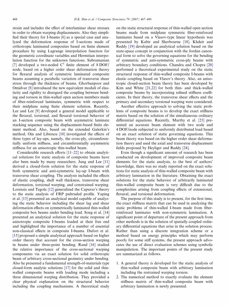
In this study, as shown in Fig. 1, three sets of coordinatesystems which are mutually interrelated are required. Thefirst coordinate system is the orthogonal Cartesian coordi-
x3
x1
x2
qo
r
n, us,υ
P
y, q
Fig. 1. Pictorial definitions of coordinates in thin-walled section.
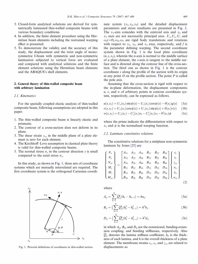
nate system (x1,x2,x3) and the detailed displacementparameters and stress resultants are presented in Fig. 2.The x1-axis coincides with the centroid axis and x2 andx3 axes are not necessarily principal axes. Ux,Uy,Uz andx1(=h),x2,x3 are rigid body translations and rotationswith respect to x1, x2, and x3 axes, respectively, and f isthe parameter defining warping. The second coordinatesystem shown in Fig. 1 is the local plate coordinate(n, s,x1), wherein the n-axis is normal to the middle surfaceof a plate element, the s-axis is tangent to the middle sur-face and is directed along the contour line of the cross-sec-tion. The third one as shown in Fig. 1 is the contourcoordinate s along the profile of the section with its originat any point O on the profile section. The point P is calledthe pole axis.
Assuming that the cross-section is rigid with respect tothe in-plane deformation, the displacement componentsu, v, and w of arbitrary points in contour coordinate sys-tem, respectively, can be expressed as follows.
uðs;x1Þ ¼U yðx1Þ sinwðsÞ�U zðx1ÞcoswðsÞ� hðx1ÞqðsÞ ð1aÞvðs;x1Þ ¼U yðx1ÞcoswðsÞþU zðx1Þ sinwðsÞþ hðx1ÞrðsÞ ð1bÞwðs;x1Þ ¼Uxðx1Þ�U 0zðx1Þx2�U 0yðx1Þx3� h0ðx1Þ/ ð1cÞ
where the prime indicate the differentiation with respect tox1 and / is the normalized warping function.
2.2. Laminate constitutive relations
The constitutive relations for a midplane non-symmetriclaminate by Jones [25] are
Nx
Ns
Nxs
Mx
Ms
Mxs
8>>>>>>>><>>>>>>>>:
9>>>>>>>>=>>>>>>>>;¼
A11 A12 A16 B11 B12 B16
A12 A22 A26 B12 B22 B26
A16 A26 A66 B16 B26 B66
B11 B12 B16 D11 D12 D16
B12 B22 B26 D12 D22 D26
B16 B26 B66 D16 D26 D66
2666666664
3777777775
ex
es
cxs
jx
js
jxs
8>>>>>>>><>>>>>>>>:
9>>>>>>>>=>>>>>>>>;ð2Þ
where
Aij ¼XN
k¼1
Qkijðhk � hk�1Þ ¼ haij ð3aÞ
Bij ¼ 12
XN
k¼1
Qkijðh2
k � h2k�1Þ ¼ h2bij ð3bÞ
Dij ¼ 13
XN
k¼1
Qkijðh3
k � h3k�1Þ ¼ h3dij ð3cÞ
in which Aij, Bij, and Dij are the extensional, bending-exten-sion coupling, and bending stiffnesses, respectively. AlsoQij denotes the lamina stiffness coefficient, hk is the thick-ness of each lamina, and h is the overall thickness of a plateelement. The membrane strains ex, es, and cxs are related todisplacements as
Ux
Uz
Uyw1 w2
w3
f
O
C
O : Shear centerC : Centroid
x2
x3
x1
(a) (b)
O : Shear centerC : Centroid
x2
x3
x1
M2F2
F1
F3
O
C
M3
M1
Mf
Fig. 2. Notation for (a) displacement parameters and (b) stress resultants.
470 D.K. Shin et al. / Composite Structures 79 (2007) 467–480
ex ¼owox1
ð4aÞ
es ¼ovos
ð4bÞ
cxs ¼owosþ ov
ox1
� 0 ð4cÞ
The axial, tangential, and twisting curvatures of the middlesurface, jx, js, and jxs are expressed as follows.
jx ¼o2uox2
1
ð5aÞ
js ¼o
2uos2
ð5bÞ
jxs ¼ �2o2u
ox1osð5cÞ
Substituting Eqs. (1a)–(1c) into Eqs. (4a) and (5a,c) yields
ex ¼ U 0x � U 00z x2 � U 00y x3 � h00/ ð6aÞ
jx ¼ U 00z sin w� U 00y cos w� h00q ð6bÞ
jxs ¼ 2h0 ð6cÞ
Assuming rs = 0 leads to Ns = Ms = 0, and es and js can beexpressed from Eq. (2) as follows.
es ¼ �1
A22D22 � B222
fðA12D22 � B12B22Þex
þ ðB12D22 � B22D12Þjx þ ðB26D22 � B22D26Þjxsg ð7aÞ
js ¼1
A22D22 � B222
fðA12B22 � A22B12Þex
þ ðB12B22 � A22D12Þjx þ ðB22B26 � A22D26Þjxsg ð7bÞ
Substituting Eqs. (7a) and (7b) into Eq. (2) gives the lami-nate stress resultants as a function of ex, jx, and jxs only.
Nx ¼ A�11ex þ B�11jx þ B�16jxs ð8aÞNxs ¼ A�16ex þ eB�16jx þ B�66jxs ð8bÞMx ¼ B�11ex þ D�11jx þ D�16jxs ð8cÞMxs ¼ B�16ex þ D�16jx þ D�66jxs ð8dÞ
where
A�11 ¼ A11 �A2
12D22 � 2A12B12B22 þ A22B212
A22D22 � B222
ð9aÞ
A�16 ¼ A16 �A12A26D22 � A12B22B26 � A26B12B22 þ A22B12B26
A22D22 � B222
ð9bÞ
B�11 ¼ B11 �A12B12D22 � A12B22D12 � B2
12B22 þ A22B12D12
A22D22 � B222
ð9cÞ
B�16 ¼ B16 �A12B26D22 � A12B22D26 � B12B22B26 þ A22B12D26
A22D22 � B222
ð9dÞ
eB�16 ¼ B16 �A26B12D22 � A26B22D12 � B12B22B26 þ A22B26D12
A22D22 � B222
ð9eÞ
B�66 ¼ B66 �A26B26D22 � A26B22D26 � B22B2
26 þ A22B26D26
A22D22 � B222
ð9fÞ
D�11 ¼ D11 �B2
12D22 � 2B12B22D12 þ A22D212
A22D22 � B222
ð9gÞ
D�16 ¼ D16 �B12B26D22 � B12B22D26 � B22B26D12 þ A22D12D26
A22D22 � B222
ð9hÞ
D�66 ¼ D66 �B2
26D22 � 2B22B26D26 þ A22D226
A22D22 � B222
ð9iÞ
2.3. Beam stress resultant–displacement relations and
strain energy
The beam stress resultants based on the principle of vir-tual work [26] that are equivalent to the distributions ofplate stress resultants acting on a cross-section of a beamare listed.
D.K. Shin et al. / Composite Structures 79 (2007) 467–480 471
F 1¼Z
CNx ds ð10aÞ
F 2¼Z
Cx2
oNx
ox1
�oMx
ox1
sinw
� �ds�m3¼�
oM3
ox1
�m3
ð10bÞ
F 3¼Z
Cx3
oNx
ox1
þoMx
ox1
cosw
� �dsþm2¼
oM2
ox1
þm2
ð10cÞM1¼ T xþT s
¼Z
C/
oNx
ox1
þqoMx
ox1
� �ds�mx�
ZCðMsxþMxsÞds
ð10dÞ
M2¼Z
CðNxx3þMx coswÞds ð10eÞ
M3¼�Z
CðN xx2�Mx sinwÞds ð10fÞ
M/¼Z
CðNxxþMxqÞds ð10gÞ
where m1, m2, m3, and mx are the moment distributions.Constitutive relations for the beam stress resultants and
the displacements are obtained by substituting Eqs. (8a)–(8d) into Eqs. (10a), (10d)–(10g)
F 1
�M2
M3
�M/
T s
8>>>>>><>>>>>>:
9>>>>>>=>>>>>>;¼
A �S2 �S3 �Sw S/
�S2 I2 I23 I/2 H c
�S3 I23 I3 I/3 �Hs
�Sw I/2 I/3 I/ H q
S/ H c �H s H q D
26666664
37777775
U 0xU 00zU 00yh00
h0
8>>>>>><>>>>>>:
9>>>>>>=>>>>>>;ð11Þ
where the detailed definitions of quantities in Eq. (11) areanalogous to those defined by Bauld and Tzeng [1] exceptfor S/ and arbitrary lamination effect. This new quantityreflects the behavior of beam by coupled laminate coeffi-cient B16.
The remaining stress resultants F2, F3, and Tx areobtained from Eqs. (10b)–(10d) with the aid of Eq. (11).Accordingly,
F 2
F 3
T x
8><>:9>=>;¼
�S3 I23 I3 I/3 �H s
�S2 I2 I23 I/2 Hc
�Sx I/2 I/3 I/ H q
264375
U 00xU 000zU 000yh000
h00
8>>>>>><>>>>>>:
9>>>>>>=>>>>>>;�
m3
�m2
mx
8><>:9>=>;ð12Þ
Eqs. (11) and (12) express the beam stress resultants interms of the beam displacement (Ux,Uy,Uz,h) and the con-stitutive relations associated with beams with thin-walledcross-section made from fiber-reinforced laminates of themidplane non-symmetric type.
The strain energy of the thin-walled composite beamduring a displacement of the cross-section can be expressedby the study which performed for the analysis of isotropicbeam by Kim and Kim [27].
P ¼ 12
Z l
oðF 1U 0x þM3U 00y �M2U 00z �M/h00 þ T sh
0Þdx1 ð13Þ
where l denotes the length of beam and substituting Eq.(11) into Eq. (13), we can obtain the following strain energyof the thin-walled composite beam with non-symmetriclamination.
P ¼ 12
Z l
oAU 02x þ I3U 002y þ I2U 002z þ 2I23U 00y U 00z þ I/h002h
þ2I/3U 00y h00 þ 2I/2U 00z h
00 þ Dh02 � 2S2U 0xU00z
�2S3U 0xU00y � 2SwU 0xh
00 þ 2S/U 0xh0 � 2HsU 00y h
0
þ2H cU 00z h0 þ 2Hqh
0h00�dx1 ð14Þ
Lastly, the equilibrium equations can be obtained by vari-ation of the above strain energy equation (14) with respectto the four displacement measures.
AU 00x � S3U 000y � S2U 000z þ S/h00 � Swh000 ¼ 0 ð15Þ� S2U 000x þ I23U 0000y þ I2U 0000z þ Hch
000 þ I/2h0000 ¼ 0 ð16Þ
� S3U 000x þ I3U 0000y þ I23U 0000z � Hsh000 þ I/3h
0000 ¼ 0 ð17Þ� S/U 00x � SwU 000x þ H sU 000y þ I/3U 0000y � H cU 000zþ I/2U 0000z � Dh00 þ I/h0000 ¼ 0 ð18Þ
3. Exact element stiffness matrix
3.1. Exact evaluation of displacement function
In this section, the exact displacement function for theanalysis of thin-walled composite beam is evaluated. Forthis, following displacement state vector consisting of 14displacement parameters is defined by
d ¼ hU 0x;U 00x ;Uy ;U 0y ;U00y ;U
000y ;U z;U 0z;U
00z ;U
000z ; h; h
0; h00; h000iT
¼ hd1; d2; d3; d4; d5; d6; d7; d8; d9; d10; d11; d12; d13; d14iT
ð19ÞIn case of evaluating the exact element stiffness matrix,
the two non-zero eigenvalues and the 12 zero eigenvaluesare generated from the eigenproblem. First, the non-zeroeigenvalues and eigenvectors of the two pairs may beexpressed as follows
ðki;ZiÞ; i ¼ 1; 2 ð20Þwhere
Zi¼hz1;i;z2;i;z3;i;z4;i;z5;i;z6;i;z7;i;z8;i;z9;i;z10;i;z11;i;z12;i;z13;i;z14;iiT
ð21ÞThe solutions of Eqs. (15)–(18) corresponding to non-zeroeigenvalues are
dI ¼ a1Z1ek1x þ a2Z2ek2x ¼ XIaI ð22Þ
472 D.K. Shin et al. / Composite Structures 79 (2007) 467–480
where
XI ¼ hZ1ek1x; Z2ek2xi ð23aÞaI ¼ ha1; a2iT ð23bÞ
In Eq. (22), XI and aI denote the 14 · 2 matrix functionmade up of the two eigensolutions and the integration con-stant vector, respectively. To evaluate the non-zero eigen-values k1 and k2 and corresponding eigenvectors Z1 andZ2, we assume the following displacement functions.
Ux ¼ aekx; Uy ¼ bekx; U z ¼ cekx; h ¼ dekx ð24a–dÞSubstituting Eqs. (24a)–(24d) into Eqs. (15)–(18) and rear-ranging them, we can obtain following equations.
Aak2 � S3bk3 � S2ck3 þ S/dk2 � Swdk3 ¼ 0 ð25aÞ
� S2ak3 þ I23bk4 þ I2ck4 þ H cdk3 þ I/2dk4 ¼ 0 ð25bÞ
� S3ak3 þ I3bk4 þ I23ck4 � H sdk3 þ I/3dk4 ¼ 0 ð25cÞ
� S/ak2 � Swak3 þ Hsbk3 þ I/3bk4 � Hcck3
þ I/2ck4 � Ddk2 þ I/dk4 ¼ 0 ð25dÞ
Eqs. (25a)–(25d) can be expressed as a matrix form.
A �S3k �S2k S/ � Swk
�S2 I23k I2k I/2kþH c
�S3 I3k I23k I/3k�Hs
�Swk� S/ I/3k2þH sk I/2k
2�H ck I/k2 �D
2666437775
a
b
c
d
8>>><>>>:9>>>=>>>;
¼
0
0
0
0
8>>><>>>:9>>>=>>>; ð26Þ
By applying the condition that the determinant of thematrix in Eq. (26) is zero, two non-zero eigenvalues k1
and k2 and two zero eigenvalues are obtained.Next, it is necessary to determine the displacement
modes corresponding to 12 zero eigenvalues. For this, fourdisplacement parameters are assumed to be
Ux ¼ n1 þ n2xþ n3
x2
2þ n4
x3
3!þ n5
x4
4!ð27aÞ
Uy ¼ f1 þ f2xþ f3
x2
2þ f4
x3
3!þ f5
x4
4!ð27bÞ
Uz ¼ g1 þ g2xþ g3
x2
2þ g4
x3
3!þ g5
x4
4!ð27cÞ
h ¼ l1 þ l2xþ l3
x2
2þ l4
x3
3!þ l5
x4
4!ð27dÞ
where ni, fi, gi, and li (i = 1–5) are the integration constantscorresponding to each displacement parameters. Substitut-ing Eqs. (27a)–(27d) into Eqs. (15)–(18) and applying theidentity condition, the following two equations areobtained.
An3 � S3f4 � S2g4 þ S/l3 ¼ 0 ð28aÞ� S/n3 þ Hsf4 � H cg4 � Dl3 ¼ 0 ð28bÞ
In Eqs. (28a) and (28b), n3 and l3 can be expressed in termsof f4 and g4.
n3 ¼1
S2/ � AD
fðH sS/ � S3DÞf4 � ðH cS/ þ S2DÞg4g ð29aÞ
l3 ¼1
S2/ � AD
ðS3S/ � AHs
� �f4 þ ðS2S/ þ AH cÞg4g ð29bÞ
Using Eqs. (29a) and (29b), the displacement parameterswith 12 undetermined parameters in Eqs. (27a)–(27d) arereduced as follows
Ux ¼ n1 þ n2xþ 1
2
HsS/ � S3D
S2/ � AD
f4x2 � 1
2
H cS/ þ S2D
S2/ � AD
g4x2
ð30aÞ
Uy ¼ f1 þ f2xþ f3
x2
2þ f4
x3
6ð30bÞ
Uz ¼ g1 þ g2xþ g3
x2
2þ g4
x3
6ð30cÞ
h ¼ l1 þ l2xþ 1
2
S3S/ � AH s
S2/ � AD
f4x2 þ 1
2
S2S/ þ AHc
S2/ � AD
g4x2
ð30dÞ
From which the homogeneous solution corresponding to12 zero eigenvalues may be written as
dII ¼ a3Z3ek3x þ a4Z4ek4x þ a5Z5ek5x þ a6Z6ek6x þ a7Z7ek7x
þ a8Z8ek8x þ a9Z9ek9x þ a10Z10ek10x þ a11Z11ek11x
þ a12Z12ek12x þ a13Z13ek13x þ a14Z14ek14x ¼ XIIaII ð31Þ
where
XII ¼ hZ3ek3x; Z4ek4x; Z5ek5x; Z6ek6x; Z7ek7x; Z8ek8x;
Z9ek9x; Z10ek10x; Z11ek11x; Z12ek12x; Z13ek13x; Z14ek14xið32aÞ
aII ¼ ha3; a4; a5; a6; a7; a8; a9; a10; a11; a12; a13; a14iT ð32bÞ
Consequently, the exact solution of the displacement statevector with respect to the integration constant vector a isobtained as follows
d ¼ XIaI þ XIIaII ¼ Xa ð33Þwhere the detailed components of X and a are given inAppendix I.
And then, we consider the following displacement statevector consisting of nine displacement parameters.
d� ¼ hU 0x;U 00x ;U 00y ;U 000y ;U 00z ;U 000z ; h0; h00; h000iT ð34Þ
Based on Eq. (33), the selected displacement state vector d*
can be evaluated as
d� ¼ X�a ð35Þwhere X* is the 9 · 14 matrix function.
Now, it is necessary that complex coefficient vector a isrepresented with respect to 14 nodal displacement compo-nents including warping deformation. For this, the nodal
D.K. Shin et al. / Composite Structures 79 (2007) 467–480 473
displacement vector at p and q which means the two endsof the member (x = 0, l) is defined by
Ue ¼ hUp;UqiT ð36aÞUj ¼ hUj
x ;Ujy ;U
jz ;x
j1 ;x
j2 ;x
j3 ; f
jiT; j ¼ p; q ð36bÞ
where
Up ¼ hUxð0Þ;U yð0Þ;Uzð0Þ; hð0Þ;�U 0zð0Þ;U 0yð0Þ;�h0ð0ÞiT
ð37aÞUq ¼ hUxðlÞ;U yðlÞ;UzðlÞ; hðlÞ;�U 0zðlÞ;U 0yðlÞ;�h0ðlÞiT
ð37bÞ
By substituting coordinates of the ends of member (x = 0, l)into Eq. (33) and accounting for Eqs. (36a) and (36b), thenodal displacement vector Ue can be obtained as follows
Ue ¼ Ha ð38Þwhere H is easily evaluated from X and the detailed expres-sion is given in Appendix II.
Finally, elimination of a from Eq. (35) using Eq. (38)yields the displacement state vector consisting of 14 dis-placement components.
d� ¼ X�H�1Ue ð39ÞIt should be noticed that X*H�1 in Eq. (39) is the exactinterpolation function not approximate one.
3.2. Calculation of exact element stiffness matrix
Next, we consider the nodal force vector at the two endsp and q defined by
Fe ¼ hFp;FqiT ð40Þwhere
Fi ¼ hF i1; F
i2; F
i3;M
i1;M
i2;M
i3;M
i/i
T; i ¼ p; q ð41Þ
Also using Eq. (19), the force–deformation relations inEqs. (11) and (12) can be rewritten in a matrix form.
F ¼ Sd� ð42Þin which
F ¼ hF 1; F 2; F 3;M1;M2;M3;M/iT ð43aÞ
S ¼
A � �S3 � �S2 � S/ �Sw �� S3 � �I3 � �I23 � H s �I/3
� S2 � �I23 � �I2 � �Hc �I/2
S/ Sw �H s �I/3 H c �I/2 D � �I/
S2 � �I23 � �I2 � �H c �I/2 ��S3 � I3 � I23 � �H s I/3 �Sw � �I/3 � �I/2 � �H q �I/ �
2666666666664
3777777777775ð43bÞ
Now, substitution of Eq. (39) into Eq. (42) leads to
F ¼ SX�H�1Ue ð44Þ
and nodal forces at ends of the element are evaluated as
Fp ¼ �Fð0Þ ¼ �SX�ð0ÞH�1Ue ð45aÞFq ¼ FðlÞ ¼ SX�ðlÞH�1Ue ð45bÞ
Consequently, the exact element stiffness matrix K ofthin-walled composite beam with arbitrary stackingsequence is calculated as follows
Fe ¼ KUe ð46Þwhere
K ¼ �SX�ð0ÞH�1
SX�ðlÞH�1
" #ð47Þ
4. Analytical solution
In this section, the coupled differential equations gov-erning the elastic behavior of thin-walled composite beamswith midplane symmetric lamination are solved, as a spe-cial case, by an analytical method. If the origin of theCartesian coordinate system coincides with the centroidof the cross-section, the S2 and S3 in Eq. (11) are zero,when the origin of the contour coordinate system coincideswith a principal origin, Sw is zero. Also I/2 and I/3 are zerowhen the pole coincides with the principal pole and I23 iszero when the axes of the Cartesian coordinate systemcoincides with the principal axes.
In this study, we consider the thin-walled beams withsimply supported, clamped and cantilevered boundary con-ditions at two ends. First, in case that the concentrated ver-tical force F is acting at the point u for simply supportedbeam, the governing equations from Eq. (11) are as follows
� I2U 00z1 � H ch01 ¼ F 1� u
l
� �x ð0 6 x 6 uÞ ð48aÞ
� I2U 00z2 � H ch02 ¼ F u 1� x
l
� �ðu 6 x 6 lÞ ð48bÞ
where subscripts ‘1’ and ‘2’ indicate the displacement at0 6 x 6 u and u 6 x 6 l, respectively. Also, since the bend-ing moment M3 and the torsional moment M1 are zero, fol-lowing equations are obtained from Eq. (11).
M3 ¼ I3U 00y � H sh0 ¼ 0 ð49Þ
M1 ¼ HcU 00z � HsU 00y þ Dh0 � Is/h000 ¼ 0 ð50Þ
From Eqs. (48)–(50), the equations for twist angle h canbe expressed as
Is/h0001 � Qh01 ¼
HcFI2
ul� 1
� �x ð0 6 x 6 uÞ ð51aÞ
Is/h0002 � Qh02 ¼
HcFI2
u 1� xl
� �ðu 6 x 6 lÞ ð51bÞ
where
Q ¼ D� H 2c
I2
� H 2s
I3
ð52Þ
474 D.K. Shin et al. / Composite Structures 79 (2007) 467–480
The solutions of Eqs. (51a) and (51b) are
h1ðxÞ ¼ i1 þ i2 cosh vxþ i3 sinh vx
� H cF2QI2
ul� 1
� �x2 ð0 6 x 6 uÞ ð53aÞ
h2ðxÞ ¼ n1 þ n2 cosh vxþ n3 sinh vx
� HcF u2QI2
2x� x2
l
� �ðu 6 x 6 lÞ ð53bÞ
where
v ¼ffiffiffiffiffiffiffiffiffiffiffiffiffiffiffiffiffiffiffiffiffiffiffiffiffiffiffiffiffiffiffiffiffiDIs/
� H 2c
I2Is/
� H 2s
I3Is/
sð54Þ
The solutions for the lateral displacement Uy and the verti-cal displacement Uz can be evaluated from Eqs. (48) and(49).
U y1ðxÞ ¼H s
I3
i1xþ i2
sinhvxvþ i3
coshvxv�H cFx3
6QI2
ul� 1
� � �þ e1xþ e2 ð55aÞ
U y2ðxÞ ¼H s
I3
n1xþ n2
sinhvxvþ n3
coshvxv�HcF u
6QI2
1� u3l
� �x2
�þ e3xþ e4 ð55bÞ
and
Uz1ðxÞ ¼�Hc
I2
i1xþ i2
sinhvxvþ i3
coshvxv�HcFx3
6QI2
ul�1
� � �� F
6I2
1�ul
� �x2þ e5xþ e6 ð56aÞ
Uz2ðxÞ ¼�Hc
I2
n1xþn2
sinhvxvþn3
coshvxv�HcFx2u
2QI2
1� x3l
� � ��Fx2u
6I2
3� xl
� �þ e7xþ e8 ð56bÞ
In Eqs. (53), (55) and (56), 14 integral constants i1–i3, n1–n3,and e1–e8 can be determined from the boundary conditionsat both ends of beam and the continuous conditions for thedisplacement and the gradient at x = u.
For the cantilevered beam with the concentrated force F
acting at the distance u from the clamped end, the govern-ing equations are, from Eq. (11),
� I2U 00z � H ch0 ¼ F ðx� uÞ ð57Þ
I3U 00y � H sh0 ¼ 0 ð58Þ
HcU 00z � HsU 00y þ Dh0 � I s/h000 ¼ 0 ð59Þ
The general solutions for the displacements and the twistangle are evaluated from Eqs. (57)–(59) using the boundarycondition at x = 0 and x = u.
UyðxÞ ¼Hs
I3
m� x� sinh vxv
� ��þHcF
QI2
uð1� cosh vxÞv2
þ x2
2
x3� u
� � � ð60Þ
UzðxÞ ¼ �H s
I2
m� x� sinh vxv
� ��þHcF
QI2
uð1� cosh vxÞv2
þ x2
2
x3� u
� � � � Fx2
6I2
ðx� 3uÞ
ð61Þ
hðxÞ ¼ �m� þ m� cosh vxþ HcFQI2
u sinh vxv
þ x2ðx� 2uÞ
�ð62Þ
where
m� ¼ �HcFQI2
ðIs/v sinh vuþ Hq cosh vuÞuþ Is
/
Isuv2 cosh vuþ Hqv sinh vu
ð63Þ
Similarly, the lateral and vertical displacements and thetwist angle for the clamped beam subjected to the force F atx = u can be obtained.
Uy1ðxÞ¼Hs
I3
i1xþ i2sinhvx
vþ i3
coshvxvþH cx2
6QI2
ð3Mp2�F p
3xÞ �
þ e1xþ e2 ð64aÞ
Uy2ðxÞ¼Hs
I3
n1xþn2
sinhvxvþn3
coshvxv
�þHcx2
6QI2
f3ðMq2�F q
3lÞþF q3xg þ e3xþ e4 ð64bÞ
and
Uz1ðxÞ¼H s
I2
i1xþ i2
sinhvxvþ i3
coshvxvþHcx2
6QI2
ð3Mp2�F p
3xÞ �
� x2
6I2
ð3Mp2�F p
3xÞþ e5xþ e6 ð65aÞ
Uz2ðxÞ¼�H s
I2
n1xþn2
sinhvxvþn3
coshvxv
�þHcx2
6QI2
f3ðMq2�F q
3lÞþF q3xg
� x2
6I2
f3ðMq2�F q
3lÞþF q3xgþ e7xþ e8 ð65bÞ
and
h1ðxÞ ¼ i1 þ i2 cosh vxþ i3 sinh vx
þ Hcx2QI2
ð2Mp2 � F p
3xÞ ð66aÞ
h2ðxÞ ¼ n1 þ n2 cosh vxþ n3 sinh vx
þ Hcx2QI2
f2ðMq2 � F q
3lÞ þ F q3xg ð66bÞ
where Mp2 and Mq
2 are the bending moments about x2-axisat the clamped ends p and q, respectively. F p
3 and F q3 are
the vertical reactions at p and q, respectively.For the special case that the stacking sequences of the
flange and the web are specially orthotropic and thecross-sections are doubly- or mono-symmetric about x2-axis, the bending and torsional actions are decoupled andthe lateral displacement Uy and the twist angle h are zero.
D.K. Shin et al. / Composite Structures 79 (2007) 467–480 475
In this case, for three boundary conditions, the vertical dis-placements Uz are
(i) Beam with simply supported boundary condition
U zðxÞ ¼F ðl� uÞx
6lI2
fl2 � ðl� uÞ2 � x2g ð67Þ
(ii) Beam with clamped boundary condition
U zðxÞ ¼F ðl� uÞ2x2
6l3I2
f3ul2 � ð2uþ lÞxg ð0 6 x 6 uÞ
ð68aÞ
U zðxÞ ¼F u2ðl� xÞ2
6l3I2
fð3l2 � 2uÞx� ulg ðu 6 x 6 lÞ
ð68bÞ
(iii) Beam with cantilevered boundary condition
U zðxÞ ¼Fx2
6I2
ð3u� xÞ ð69Þ
2b1
5 cm
0.104 cm
0.208 cm
4 cm
0.312 cm
x2
x3
Fig. 3. Cross-section of the mono-symmetric I-beam with symmetriclamination.
5. Finite element formulation
The finite element model including the effects ofrestrained warping and non-symmetric lamination schemeis presented. To accurately express the element deforma-tion, pertinent shape functions are necessary. In this study,the cubic Hermitian polynomials are adopted to interpolatedisplacement parameters that are defined at the centroidaxis. This beam element has two nodes per one elementand seven nodal degrees of freedom. As a result, the ele-ment displacement parameters can be interpolated withrespect to the nodal displacements as follows
U x ¼ k1up þ k2gp þ k3uq þ k4gq ð70aÞU y ¼ k1vp þ k2x
p3 þ k3vq þ k4x
q3 ð70bÞ
U z ¼ k1wp � k2xp2 þ k3wq � k4x
q2 ð70cÞ
h ¼ k1xp1 � k2f p þ k3x
q1 � k4f q ð70dÞ
where
up ¼ U xð0Þ; gp ¼ U 0xð0Þ; vp ¼ U yð0Þ;wp ¼ Uzð0Þ; xp
1 ¼ hð0Þ; xp2 ¼ �U 0zð0Þ;
xp3 ¼ U 0yð0Þ; f p ¼ �h0ð0Þ ð71a–hÞ
and ki, (i = 1–4) denotes cubic Hermitian polynomial asfollows
k1 ¼ 2x1
l
� �3
� 3x1
l
� �2
þ 1
k2 ¼x1
l
� �3
� 2x1
l
� �2
þ x1
l
�l
k3 ¼ �2x1
l
� �3
þ 3x1
l
� �2
k4 ¼x1
l
� �3
� x1
l
� �2 �
l
ð72a–dÞ
Substituting Eqs. (70a)–(70d) into the strain energy equa-tion (14) and integrating along the element length, the equi-librium equation of a thin-walled composite beam witharbitrary lamination is obtained in a matrix form as
KeUe ¼ Fe ð73Þwhere Ke is the element elastic stiffness matrix in a localcoordinate and Ue and Fe are the nodal displacement andforce vectors, respectively. Here, stiffness matrix is evalu-ated using a Gauss numerical integration scheme. Then,the assembly of the element stiffness matrix for the entirestructure based on the coordinate transformation leads tothe equilibrium matrix equation in a global coordinatesystem.
6. Numerical examples
In order to illustrate the validity and the accuracy of thenumerical method proposed in this study, the spatially cou-pled elastic analysis of thin-walled composite beam withsymmetric and non-symmetric laminations is performed.The solutions evaluated by this study are compared withanalytical solutions and the results from the finite elementmethods using the thin-walled Hermitian beam elementsand the ABAQUS’s shell elements [28].
6.1. Mono-symmetric I-beam with symmetric lamination
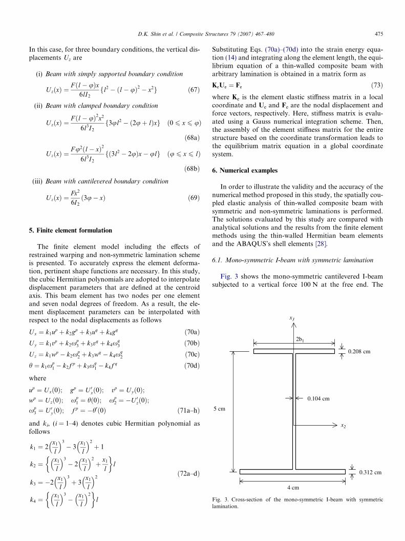
Fig. 3 shows the mono-symmetric cantilevered I-beamsubjected to a vertical force 100 N at the free end. The
476 D.K. Shin et al. / Composite Structures 79 (2007) 467–480
material of beam is glass–epoxy and the length of beam is250 cm. The material properties of beam are as follows.
E1 ¼ 53:78 GPa, E2 ¼ E3 ¼ 17:93 GPa,
G12 ¼ G13 ¼ 8:96 GPa
G23 ¼ 3:45 GPa, m12 ¼ m13 ¼ 0:25; m23 ¼ 0:34 ð74Þ
where subscripts ‘1’ and ‘2’ correspond to directions paral-lel and perpendicular to fibers, respectively.
In the first example, all constituent flanges and web areassumed to be symmetrically laminated with respect to itsmidplane. The half top flange width of the beam b1 is1.5 cm and the total thicknesses of top flange, bottomflange, and web are assumed to be 0.208 cm, 0.312 cm,and 0.104 cm, respectively. The detailed stacking sequencesof I-beam considered in this example are summarized inTable 1. It is noted that since the top and bottom flangesare symmetrically laminated, the coupling stiffnesses I23,I/2, S2, S3, Sw, and S/ become zero. The vertical displace-ment at the free end of cantilevered composite beam by thisstudy is presented in Table 2 for the laminates considered.
Table 3Twist angle at the free end of mono-symmetric cantilevered I-beam with symm
This study Analytical solution Hermitian beam e
1 2
QSISO 2.4706 2.4706 2.1529 2.3ANG0 0 0 0 0ANG15 1.9038 1.9038 1.6907 1.8ANG30 2.5271 2.5271 2.2000 2.4ANG45 2.1249 2.1249 1.8204 2.0ANG60 1.2013 1.2013 1.0252 1.1ANG75 0.43983 0.43983 0.37780 0.4
Table 2Vertical displacement at the free end of mono-symmetric cantilevered I-beam with symmetric lamination (cm)
This study Analyticalsolution
Hermitian beamelements
ABAQUS
QSISO 14.216 14.216 14.216 14.25ANG0 8.2223 8.2223 8.2223 8.278ANG15 9.1007 9.1007 9.1007 9.146ANG30 12.256 12.256 12.257 12.28ANG45 17.705 17.705 17.705 17.72ANG60 22.376 22.376 22.376 22.40ANG75 24.289 24.289 24.289 24.33
Table 1Stacking sequence of mono-symmetric I-beam
Top flange Bottom flange Web
QSISO [0/45/90/�45]2S [0/45/90/�45]3S [0/45/90/�45]SANG0 [0]16 [0]24 [0]8ANG15 [15/�15]4S [15/�15]6S [15/�15]2S
ANG30 [30/�30]4S [30/�30]6S [30/�30]2S
ANG45 [45/�45]4S [45/�45]6S [45/�45]2S
ANG60 [60/�60]4S [60/�60]6S [60/�60]2S
ANG75 [75/�75]4S [75/�75]6S [75/�75]2S
For comparison, the analytical solutions and the results by1 Hermitian beam element and 600 nine-noded ABAQUS’sshell elements (S9R5) are presented. It can be found fromTable 2 that the results obtained from the present staticstiffness matrix coincide with the analytical solutions andthe finite element solutions using Hermitian beam elementand are in an excellent agreement with the ABAQUS’ssolutions. It should be noted that the displacementsobtained from the present static stiffness matrix is exactsince this displacement satisfies the solution of a simulta-neous ordinary differential equations exactly.
The twist angles at the free end of beam by this studyusing only a single element are presented and compared withthe analytical solutions and the finite element results byusing various numbers of Hermitian beam elements andABAQUS’ shell elements in Table 3. As shown in Table 3,all the present results coincide with the analytical solutionswhile a large number of Hermitian beam elements arerequired to achieve sufficient accuracy for the twist angle.
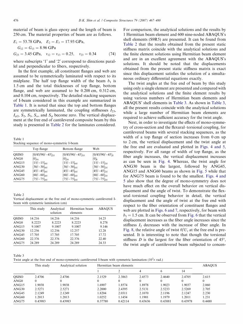
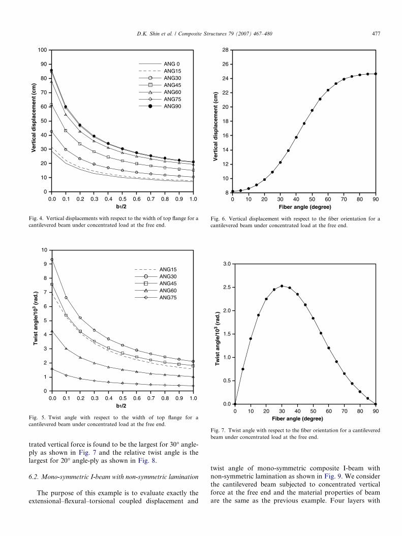
Next, in order to investigate the effects of mono-symme-try of cross-section and the flexural–torsional coupling, forcantilevered beams with several stacking sequences, as thewidth of a top flange of section increases from 0 cm upto 2 cm, the vertical displacement and the twist angle atthe free end are evaluated and plotted in Figs. 4 and 5,respectively. For all range of width of top flange, as thefiber angle increases, the vertical displacement increasesas can be seen in Fig. 4. Whereas, the twist angle forANG30 beam is the largest, followed by ANG45,ANG15 and ANG60 beams as shown in Fig. 5 while thatfor ANG75 beam is found to be the smallest. Figs. 4 and5 also show that the degree of mono-symmetry does nothave much effect on the overall behavior on vertical dis-placement and the angle of twist. To demonstrate the flex-ural–torsional coupling behavior in detail, the verticaldisplacement and the angle of twist at the free end withrespect to the fiber orientation of constituent flanges andweb are plotted in Figs. 6 and 7, respectively, for beam withb1 = 1.5 cm. It can be observed from Fig. 6 that the verticaldisplacement increases as the fiber angle increases since thestiffness I2 decreases with the increase of fiber angle. InFig. 8, the relative angle of twist h/Uz at the free end is pre-sented. It is interesting to note that though the torsionalstiffness D is the largest for the fiber orientation of 45�,the twist angle of cantilevered beam subjected to concen-
etric lamination (103· rad.)
lements ABAQUS
4 6 14
863 2.4573 2.4640 2.4705 2.6150 0 0 0
574 1.8978 1.9023 1.9037 2.060395 2.5131 2.5233 2.5269 2.705311 2.1070 2.1196 2.1247 2.230454 1.1901 1.1979 1.2011 1.2312114 0.43636 0.43881 0.43978 0.4480
0.0 0.1 0.2 0.3 0.4 0.5 0.6 0.7 0.8 0.9 1.0b1/2
0
20
40
60
80
100
10
30
50
70
90
Ver
tica
l dis
pla
cem
ent (
cm)
ANG 0ANG15ANG30ANG45ANG60ANG75ANG90
Fig. 4. Vertical displacements with respect to the width of top flange for acantilevered beam under concentrated load at the free end.
0.0 0.1 0.2 0.3 0.4 0.5 0.6 0.7 0.8 0.9 1.0b1/2
0
2
4
6
8
10
1
3
5
7
9
Tw
ist
ang
le/1
03 (r
ad.)
ANG15ANG30ANG45ANG60ANG75
Fig. 5. Twist angle with respect to the width of top flange for acantilevered beam under concentrated load at the free end.
0 20 40 60 8010 30 50 70 90Fiber angle (degree)
8
12
16
20
24
28
10
14
18
22
26
Ver
tica
l d
isp
lace
men
t (c
m)
Fig. 6. Vertical displacement with respect to the fiber orientation for acantilevered beam under concentrated load at the free end.
0 20 40 60 8010 30 50 70 90Fiber angle (degree)
0.0
1.0
2.0
3.0
0.5
1.5
2.5
Tw
ist
ang
le/1
03 (r
ad.)
Fig. 7. Twist angle with respect to the fiber orientation for a cantileveredbeam under concentrated load at the free end.
D.K. Shin et al. / Composite Structures 79 (2007) 467–480 477
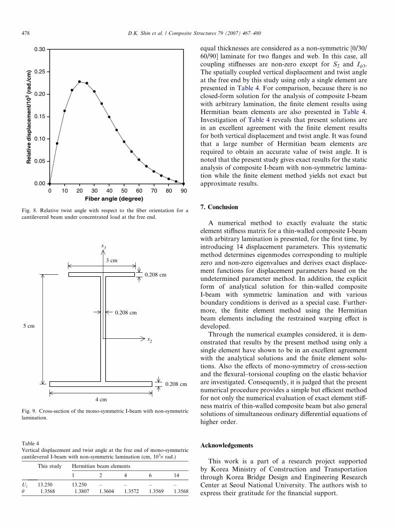
trated vertical force is found to be the largest for 30� angle-ply as shown in Fig. 7 and the relative twist angle is thelargest for 20� angle-ply as shown in Fig. 8.
6.2. Mono-symmetric I-beam with non-symmetric lamination
The purpose of this example is to evaluate exactly theextensional–flexural–torsional coupled displacement and
twist angle of mono-symmetric composite I-beam withnon-symmetric lamination as shown in Fig. 9. We considerthe cantilevered beam subjected to concentrated verticalforce at the free end and the material properties of beamare the same as the previous example. Four layers with
0 20 40 60 8010 30 50 70 90
Fiber angle (degree)
0.00
0.10
0.20
0.30
0.05
0.15
0.25
Rel
ativ
e d
isp
lace
men
t/10
3 (r
ad./c
m)
Fig. 8. Relative twist angle with respect to the fiber orientation for acantilevered beam under concentrated load at the free end.
5 cm
0.208 cm
4 cm
0.208 cm
3 cm
0.208 cm
x3
x2
Fig. 9. Cross-section of the mono-symmetric I-beam with non-symmetriclamination.
Table 4Vertical displacement and twist angle at the free end of mono-symmetriccantilevered I-beam with non-symmetric lamination (cm, 103· rad.)
This study Hermitian beam elements
1 2 4 6 14
Uz 13.250 13.250 – – – –h 1.3568 1.3807 1.3604 1.3572 1.3569 1.3568
478 D.K. Shin et al. / Composite Structures 79 (2007) 467–480
equal thicknesses are considered as a non-symmetric [0/30/60/90] laminate for two flanges and web. In this case, allcoupling stiffnesses are non-zero except for S2 and I/3.The spatially coupled vertical displacement and twist angleat the free end by this study using only a single element arepresented in Table 4. For comparison, because there is noclosed-form solution for the analysis of composite I-beamwith arbitrary lamination, the finite element results usingHermitian beam elements are also presented in Table 4.Investigation of Table 4 reveals that present solutions arein an excellent agreement with the finite element resultsfor both vertical displacement and twist angle. It was foundthat a large number of Hermitian beam elements arerequired to obtain an accurate value of twist angle. It isnoted that the present study gives exact results for the staticanalysis of composite I-beam with non-symmetric lamina-tion while the finite element method yields not exact butapproximate results.
7. Conclusion
A numerical method to exactly evaluate the staticelement stiffness matrix for a thin-walled composite I-beamwith arbitrary lamination is presented, for the first time, byintroducing 14 displacement parameters. This systematicmethod determines eigenmodes corresponding to multiplezero and non-zero eigenvalues and derives exact displace-ment functions for displacement parameters based on theundetermined parameter method. In addition, the explicitform of analytical solution for thin-walled compositeI-beam with symmetric lamination and with variousboundary conditions is derived as a special case. Further-more, the finite element method using the Hermitianbeam elements including the restrained warping effect isdeveloped.
Through the numerical examples considered, it is dem-onstrated that results by the present method using only asingle element have shown to be in an excellent agreementwith the analytical solutions and the finite element solu-tions. Also the effects of mono-symmetry of cross-sectionand the flexural–torsional coupling on the elastic behaviorare investigated. Consequently, it is judged that the presentnumerical procedure provides a simple but efficient methodfor not only the numerical evaluation of exact element stiff-ness matrix of thin-walled composite beam but also generalsolutions of simultaneous ordinary differential equations ofhigher order.
Acknowledgements
This work is a part of a research project supportedby Korea Ministry of Construction and Transportationthrough Korea Bridge Design and Engineering ResearchCenter at Seoul National University. The authors wish toexpress their gratitude for the financial support.
D.K. Shin et al. / Composite Structures 79 (2007) 467–480 479
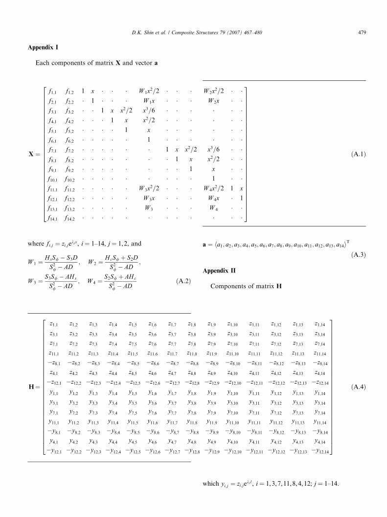
Appendix I
Each components of matrix X and vector a
X ¼
f1;1 f1;2 1 x � � � W 1x2=2 � � � W 2x2=2 � �f2;1 f2;2 � 1 � � � W 1x � � � W 2x � �f3;1 f3;2 � � 1 x x2=2 x3=6 � � � � � �f4;1 f4;2 � � � 1 x x2=2 � � � � � �f5;1 f5;2 � � � � 1 x � � � � � �f6;1 f6;2 � � � � � 1 � � � � � �f7;1 f7;2 � � � � � � 1 x x2=2 x3=6 � �f8;1 f8;2 � � � � � � � 1 x x2=2 � �f9;1 f9;2 � � � � � � � � 1 x � �f10;1 f10;2 � � � � � � � � � 1 � �f11;1 f11;2 � � � � � W 3x2=2 � � � W 4x2=2 1 x
f12;1 f12;2 � � � � � W 3x � � � W 4x � 1
f13;1 f13;2 � � � � � W 3 � � � W 4 � �f14;1 f14;2 � � � � � � � � � � � �
2666666666666666666666666666664
3777777777777777777777777777775
ðA:1Þ
where fi;j ¼ zi;jekjx, i = 1–14, j = 1,2, and
W 1 ¼HsS/ � S3D
S2/ � AD
; W 2 ¼HcS/ þ S2D
S2/ � AD
;
W 3 ¼S3S/ � AH s
S2/ � AD
; W 4 ¼S2S/ þ AH c
S2/ � AD
ðA:2Þ
H¼
z1;1 z1;2 z1;3 z1;4 z1;5 z1;6 z1;7 z1;8
z3;1 z3;2 z3;3 z3;4 z3;5 z3;6 z3;7 z3;8
z7;1 z7;2 z7;3 z7;4 z7;5 z7;6 z7;7 z7;8
z11;1 z11;2 z11;3 z11;4 z11;5 z11;6 z11;7 z11;8
�z8;1 �z8;2 �z8;3 �z8;4 �z8;5 �z8;6 �z8;7 �z8;8
z4;1 z4;2 z4;3 z4;4 z4;5 z4;6 z4;7 z4;8
�z12;1 �z12;2 �z12;3 �z12;4 �z12;5 �z12;6 �z12;7 �z12;8
y1;1 y1;2 y1;3 y1;4 y1;5 y1;6 y1;7 y1;8
y3;1 y3;2 y3;3 y3;4 y3;5 y3;6 y3;7 y3;8
y7;1 y7;2 y7;3 y7;4 y7;5 y7;6 y7;7 y7;8
y11;1 y11;2 y11;3 y11;4 y11;5 y11;6 y11;7 y11;8
�y8;1 �y8;2 �y8;3 �y8;4 �y8;5 �y8;6 �y8;7 �y8;8
y4;1 y4;2 y4;3 y4;4 y4;5 y4;6 y4;7 y4;8
�y12;1 �y12;2 �y12;3 �y12;4 �y12;5 �y12;6 �y12;7 �y12;8
2666666666666666666666666666664
a ¼ ha1; a2; a3; a4; a5; a6; a7; a8; a9; a10; a11; a12; a13; a14iT
ðA:3Þ
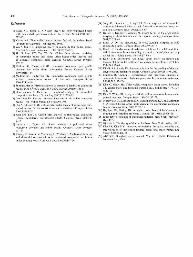
Appendix II
Components of matrix H
z1;9 z1;10 z1;11 z1;12 z1;13 z1;14
z3;9 z3;10 z3;11 z3;12 z3;13 z3;14
z7;9 z7;10 z7;11 z7;12 z7;13 z7;14
z11;9 z11;10 z11;11 z11;12 z11;13 z11;14
�z8;9 �z8;10 �z8;11 �z8;12 �z8;13 �z8;14
z4;9 z4;10 z4;11 z4;12 z4;13 z4;14
�z12;9 �z12;10 �z12;11 �z12;12 �z12;13 �z12;14
y1;9 y1;10 y1;11 y1;12 y1;13 y1;14
y3;9 y3;10 y3;11 y3;12 y3;13 y3;14
y7;9 y7;10 y7;11 y7;12 y7;13 y7;14
y11;9 y11;10 y11;11 y11;12 y11;13 y11;14
�y8;9 �y8;10 �y8;11 �y8;12 �y8;13 �y8;14
y4;9 y4;10 y4;11 y4;12 y4;13 y4;14
�y12;9 �y12;10 �y12;11 �y12;12 �y12;13 �y12;14
3777777777777777777777777777775
ðA:4Þ
which yi;j ¼ zi;jekil, i = 1,3,7,11,8,4,12; j = 1–14.
480 D.K. Shin et al. / Composite Structures 79 (2007) 467–480
References
[1] Bauld NR, Tzeng L. A Vlasov theory for fiber-reinforced beamswith thin-walled open cross sections. Int J Solids Struct 1984;20(3):277–97.
[2] Vlasov VZ. Thin walled elastic beams. 2nd ed. Jerusalem: IsraelProgram for Scientific Transactions; 1961.
[3] Wu X, Sun CT. Simplified theory for composite thin-walled beams.Am Inst Aeronaut Astronaut J 1992;30(12):2945–51.
[4] Shi G, Lam KY, Tay TE. On efficient finite element modelingof composite beams and plates using higher-order theories andan accurate composite beam element. Compos Struct 1998;41:159–65.
[5] Maddur SS, Chaturvedi SK. Laminated composite open profilesections: first order shear deformation theory. Compos Struct1999;45:105–14.
[6] Maddur SS, Chaturvedi SK. Laminated composite open profilesections: non-uniform torsion of I-sections. Compos Struct2000;50:159–69.
[7] Subramanian P. Flexural analysis of symmetric laminated compositebeams using C1 finite element. Compos Struct 2001;54:121–6.
[8] Ghorbanpoor A, Omidvar B. Simplified analysis of thin-walledcomposite members. J Struct Eng 1996;122:1379–83.
[9] Lee J, Lee SH. Flexural–torsional behavior of thin-walled compositebeams. Thin-Walled Struct 2004;42:1293–305.
[10] Oin Z, Librescu L. On a shear-deformable theory of anisotropic thin-walled beams: further contribution and validations. Compos Struct2002;56:345–58.
[11] Jung SN, Lee JY. Closed-form analysis of thin-walled compositeI-beams considering non-classical effects. Compos Struct 2003;60:9–17.
[12] Lorenzis L, Tegola AL. Static behavior of pultruded fiber-reinforced polymer thin-walled beams. Compos Struct 2003;60:231–44.
[13] Yaping W, Yuanlin Z, Yuanming L, Weideng P. Analysis of shear lagand shear deformation effects in laminated composite box beamsunder bending loads. Compos Struct 2002;55:147–56.
[14] Song O, Librescu L, Jeong NH. Static response of thin-walledcomposite I-beams loaded at their free-end cross section: analyticalsolution. Compos Struct 2001;52:55–65.
[15] Dufort L, Drapier S, Grediac M. Closed-form for the cross-sectionwarping in short beams under three-point bending. Compos Struct2001;52:223–46.
[16] Rand O. On the importance of cross-sectional warping in solidcomposite beams. Compos Struct 2000;49:393–7.
[17] Rand O. Fundamental closed-form solutions for solid and thin-walled composite beams including a complete out-of-plane warpingmodel. Int J Solids Struct 1998;35:2775–93.
[18] Kabir MZ, Sherbourne AN. Shear strain effects on flexure andtorsion of thin-walled pultruded composite beams. Can J Civil Eng1999;26:852–68.
[19] Khedir AA, Reddy JN. An exact solution for the bending of thin andthick cross-ply laminated beams. Compos Struct 1997;37:195–203.
[20] Chandra R, Chopra I. Experimental and theoretical analysis ofcomposite I-beam with elastic coupling. Am Inst Aeronaut AstronautJ 1991;29:2197–206.
[21] Kim C, White SR. Thick-walled composite beam theory including3-D elastic effects and torsional warping. Int J Solids Struct 1997;34:4237–59.
[22] Kim C, White SR. Analysis of thick hollow composite beams undergeneral loadings. Compos Struct 1996;34:263–77.
[23] Murthy MVVS, Mahapatra DR, Badarinarayana K, GopalakrishnanS. A refined higher order finite element for asymmetric compositebeams. Compos Struct 2005;67:27–35.
[24] Heyliger PR, Reddy JN. A higher order beam finite element forbending and vibration problems. J Sound Vib 1988;126:309–26.
[25] Jones RM. Mechanics of composite material. New York: McGraw-Hill; 1975.
[26] Gjelsvik A. The theory of thin-walled bars. New York: Wiley; 1981.[27] Kim SB, Kim MY. Improved formulation for spatial stability and
free vibration of thin-walled tapered beams and space frames. EngStruct 2000;22:446–58.
[28] ABAQUS. Standard user’s manual, Ver. 6.1, Hibbit, Kalsson &Sorensen Inc.; 2003.


