Embed Size (px)
Citation preview

1
EXCESS HEAT IN ELECTROLYSIS EXPERIMENTS AT ENERGETICS TECHNOLOGIES
I. Dardik, T. Zilov, H. Branover, A. El-Boher, E. Greenspan, B. Khachatorov, V. Krakov, S. Lesin, and M. Tsirlin
Energetics Technologies Ltd.
Omer, [email protected]
Presented at the11th
International Conference on Cold Fusion, ICCF-11Marseilles, France
November 1 -
6, 2004

2
CONTENTS1. Presentation objective2. SuperWaves©
used for driving the cell
3. Review of glow discharge experiments4. Description of ET electrolytic cells5. Pd Cathode and its pretreatment6. Excess heat obtained7. Excess tritium8. Material analysis

3
PRESENTATION OBJECTIVES
1. Review of SuperWave©
principles2. Review of Glow Discharge Experiments3. Description of 3 ET electrolytic cell experiments
that resulted in significant excess heat generation:
Experiment #
56
64a
64b
Cycle №
4 1 2Loading time (s)
80
5
16Excess heat (EH) (%)
80
2500
1500Duration of EH (h)
300
17
80Excess energy (EE) (MJ)
3.1
1.1
4.6Specific* EH (W/g Pd)
11
71
62Specific* EE (KeV/Pd atom)
13.5
4.8
20 (24.8)
* -
pertaining to effective part of cathode ( 6 x 0.7 cm )

4

5
OperatorParameters
set up
Superwave
form signal generation using LabView
software
Current amplifierExperimental
system
Low current
EC are driving by SuperWaves

6
t)(sin)(F 02
00 ωAt =
))(sinAt)(1(sin)(F 12
102
01 tAt ωω +=
SuperWaves formation principles
7
))](sinA1)((sinAt)[1(sin)(F 22
212
102
02 ttAt ωωω ++=
)))](sinA1)((sinA1)((sinAt)[1(sin)(F 32
322
212
102
03 tttAt ωωωω +++=

8
Glow Discharge CellCooling Water Output
Cooling Water Input
+
Ground
Tungsten Wire
Palladium Layer
D+
Plasma
100 mm
20 mm
StainlessSteel Body
Conceptual Design

9
Cell Assembly

10
ETG-1
0
10
20
30
40
50
60
70
80
0 2 4 6 8 10 12 14
Time,h
En
erg
y,k
J
Ein Eout Ex ( Excess Energy = Eout - Ein )
Experimental Results with thin Palladium film (about 1 µm) on Stainless Steel Body
ETG-1
0
0.5
1
1.5
2
2.5
3
3.5
4
0 2 4 6 8 10 12
Time, h
Pow
er, W
Pin Pout
DC
WavesWaves
Shut Down
Maximum Excess Power = 3.7 x Input Power
Total Excess Energy = 6.7 x Input Energy

11
Experimental Results with thick Palladium foil (100 µm)
ETG-2
-200
20406080
100120140160180200220240260280
10 12 14 16 18 20 22 24 26 28 30 32 34 36 38 40 42 44 46 48 50 52
Time,h
En
erg
y,k
J
Ein Eout Ex(Excess Energy=Eout-Ein)
ETG-2
0
0.2
0.4
0.6
0.8
1
1.2
1.4
1.6
1.8
10 12 14 16 18 20 22 24 26 28 30 32 34 36 38 40 42 44 46 48 50 52
Time,hP
ow
er,
W
Pin Pout
Maximum Excess Power = 0.8 x Input Power
Total Excess Energy = 0.8 x Input Energy

12
Glow Discharge Experiment Cell ETG-2-18
0
0.2
0.4
0.6
0.8
1
1.2
1.4
1.6
1.8
0 20 40 60 80 100 120 140 160 180 200 220 240 260 280 300 320 340 360 380 400 420 440 460
Time, h
Pow
er, W
-150
-100
-50
0
50
100
150
COPE
, %
Pin Pout COPE=(Pout-Pin):Pin x 100%
Excess Heat Generation during 20 days

13
Energy Production from Cell ETG-2-18
0
500
1000
1500
2000
2500
0 20 40 60 80 100 120 140 160 180 200 220 240 260 280 300 320 340 360 380 400 420 440 460
Time,h
Ene
rgy,
kJ
Ein Eout Eex
Excess Energy during 20 days

14
Energy Output after shutting down of GD Cell ETG-3-22
0
10
20
30
40
50
60
70
80
90
0 2 4 6 8Time, hr
E, k
J“Heat After Death”
Thermal Energy Stored in GD Cell SS body (m*cp
*ΔT)
Eout

15
A AC
T4
T5
Teflon
AluminaAluminum
Recombiner
Electrolyte
ET Electrolytic Cell
EC is inside a Teflon beaker that is placed inside an isoperibolic
calorimeter
0.1M LiOD
in low tritium content D2
O (230 ml)

16
Electrolytic Cell
Three cells are immersed in a constant temperature water bath of +2.50C ±
0.250C

17
Cathode & Pre-treatment
•
50 µm Pd foil, prepared by
Dr. Vittorio Violante (ENEA Frascatti, Italy)
•
Annealed at 870oC in vacuum for 1h
•
Etched:
-
in Nitric Acid 65-67%; 1 min
-
in Aqua Regia
1:1 water solution; 1 min
•
Rinsed:
- D2
O four times
-
Ethanol 95% twice
-
Ethanol Absolute once
•
Dried:
in vacuum at ambient temperature for 24 h
60 m
m
7 mm

18
05
1015202530354045505560657075
0 2 4 6 8 10 12 14 16 18 20 22 24 26 28 30
Delta T
Pow
er
Typical Calibration Curve for Electrolytic Cell Calorimeter

19
Block diagramPC
Analyzing, displaying, printout
LCR
Amplifier Temperatures (5)Current,Voltage
Cathode resistance
Wave form
Current Superwave
Cell
Water bath
Temperature
Data Logger
Measured Parameters:
-
Input Current
- Input Voltage
- Wall Temperatures
T4
and T5
-
Resistance of cathode for monitoring loading (four probe AC method)

20
Study of Influence of Modulations on Loading
1st
level of modulation Constant parametersChangeable parameters

212nd
level of modulationChangeable parameters Constant parameters
Study of Influence of Modulations on Loading

223rd
level of modulationChangeable parameters Constant parameters
Study of Influence of Modulations on Loading

23
1st
levelof modulation
2nd
level ofmodulation
3rd
level ofmodulation
Of-line RR0
versus time for Foil N056 (Dr.Violante)
1.
Study of Influence of Modulations on Loading
24Of-line RR0
versus time for Foil N056 (Dr.Violante)
2.
Study of Influence of Modulations on Loading

25Of-line RR0
versus time for Foil N056 (Dr.Violante)
3.
Study of Influence of Modulations on Loading

26
Diagram loading versus level of modulation
1.6
1.65
1.7
1.75
1.8
1.85
1 2 3 3 2 1 1 2 3 3 2 1 2 3 2 1 2 3 3
Level of modulation
Cur
rent
den
sity
, mA
/cm2
0
10
20
30
40
50
60
RR
0
RR0 j
Foil N056 (Dr.Violante)
Study of Influence of Modulations on Loading

27
Diagram loading versus level of modulation
1.7
1.75
1.8
1.85
1.9
1.95
2
1 2 3 3 2 1 1 2 3 3 2 1 2 3 2 1 2 3 3 3 3
Level of Modulation
RR
0
0
10
20
30
40
50
60
70
80
90
100
Cur
rent
den
sity
, mA
/cm2
RR0 j
Foil N051 (Dr.Violante)
Study of Influence of Modulations on Loading

28
Excess Power; Exp. # 56
Excess Power of up to ~3.5 watts; Average ~2.7 watts for ~300 h
300 h
Average Pout ~6.9 watts
Average Pinet
~3.9 watts
COPE=(Pout-Pinet):Pinet
≈
(6.9-3.9):3.9 ≈
0.8

29
Excess Energy; Exp. # 56
Excess energy of ~3.1 MJ

30
Excess Power; Exp. # 64a
Pout=KΔT
Pinet=Iin*Vin
–
P dis
Excess Power of up to 34 watts; Average ~20 watts for 17 h
17 h
Average Pinet
~0.74 watts
Average Pout ~20 watts
COPE=(Pout-Pinet):Pinet
≈
(20-0.74):0.74 ≈
25
31
Input Energy~0.033MJ
Output Energy
Excess Energy
Excess energy of ~1.1 MJ
Excess Energy; Exp. # 64a

32
Temperature Evolution, Exp. # 64a
A AC
T4T5
T1
T2
T3
T4
T5Tbath

33
ΔT=T4
-T5
Average Current Density = 7.09 mA/cm2
Cell Voltage, V
Current & Voltage; EXP. # 64a

34Loading is relatively low (~0.8)
R/Ro & Power; EXP. # 64a

35
Excess Power; Exp. # 64b
Excess Power of up to 32 watts; Average ~12 watts for 80 h
COPE=(Pout-Pinet):Pinet
≈
(12-0.72):0.72 ≈
15
Average Pout ~12 watts
Average Pinet
~0.72 watts
80 h

36Excess energy of ~4.6 MJ
Excess Energy; Exp. # 64b
Energy production from Cell ETE-4-64, second run
0.00E+00
5.00E+05
1.00E+06
1.50E+06
2.00E+06
2.50E+06
3.00E+06
3.50E+06
4.00E+06
4.50E+06
5.00E+06
0 10 20 30 40 50 60 70 80 90 100
Time, h
Ene
rgy,
Jou
le
Ein Eout Ex=Eout-Ein
37
A AC
T4T5
T1
T2
T3
Temperature Evolution, Exp. # 64b
T4
T5Tbath

38
ΔT, Current Density & Voltage ; EXP. # 64b
ΔT=T4
-T5
Average Current Density = 8.37 mA/cm2
Cell Voltage, V

39
R/Ro & Power; Exp. # 64b
Loading relatively low (~0.8)

40
Excess Tritium in # 64
•
Tritium concentration measured at end of #64 analysis ~ 250% of reference
• ~625 cm3
of D2
O has been added to make-up for evaporation; initial
inventory was 230 cm3
• Assuming TDO/D2
O evaporation rate ~ 1.0
• Estimated T effective concentration ~ 750%
•
This amount of tritium corresponds to <1J –
negligible as compared with the 5.7MJ excess energy generated.
41
Material Analysis
Diagnostics:
• Auger Electron Spectrometry
• Scanning Electron Microscopy-Energy Dispersive
Spectrometry SEM-EDS
• Transmission Electron Microscopy (TEM)
• Secondary Ion Mass Spectrometry (SIMS)

42
Material Analysis # 64 vs. 63; SEM-EDS
Surface of Pd foil after rolling and annealing at 8700C:
sample #64 sample #63

43
View of Typical Black Spot on # 64 and its composition
SEM-EDS
Element Wt % At %____________________________C 35.77 52.48 O 26.19 28.84 Na 4.92 3.77 Al 0.43 0.28 Si 1.05 0.66 Pt 0.39 0.04 S 1.44 0.79 Cl 10.68 5.31 Pd 2.55 0.42 K 11.07 4.99 Ca 5.52 2.43 Total 100.00 100.00_____________________________
44
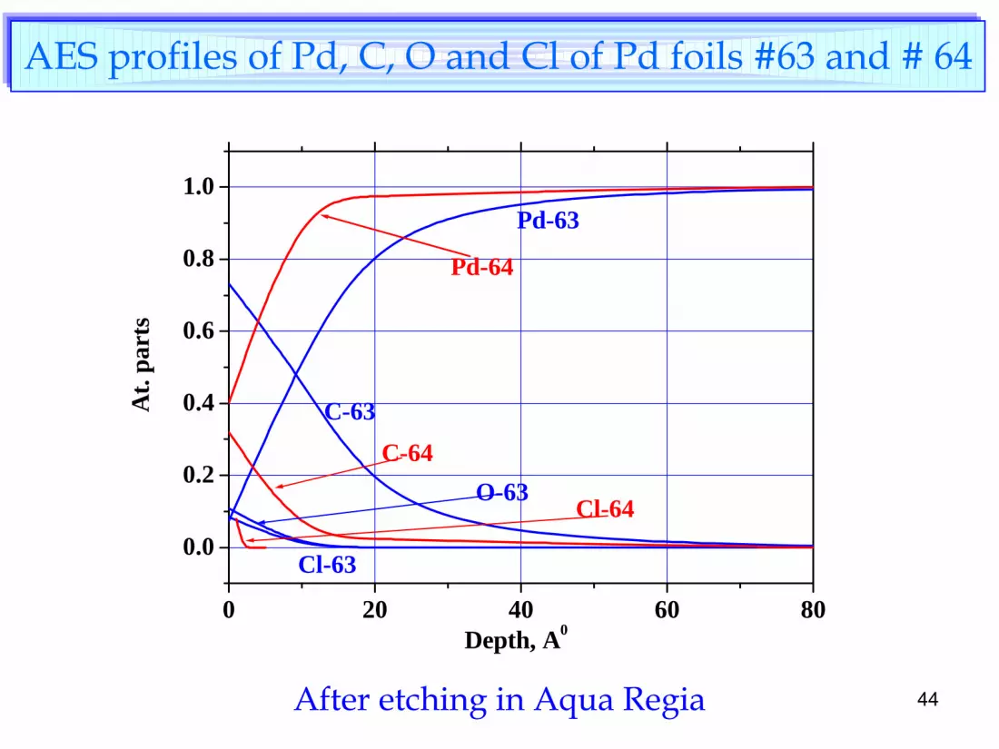
AES profiles of Pd, C, O and Cl
of Pd foils #63 and # 64
0 20 40 60 80
0.0
0.2
0.4
0.6
0.8
1.0
Cl-64
C-64
Pd-64
O-63
Cl-63
C-63
Pd-63
At.
part
s
Depth, A0
After etching in Aqua Regia

45
Sample 64. SIMS depth profiling.
0 100 200 300 400 500 600
102
103
104
105
Pd
C
Pt
CNO
S
D
H
Total
Cou
nts
Depth, A0

46
Spatial distribution of selected isotopes measured by SIMS in #64
a –
D, b -
32S, c -
total isotopes content, d -
195Pt. Scale bar -
30 µm.
a b
c d

47
The dislocations in Pd foils after annealing.
#63 #643x1010, cm-2 6x10¹⁰, cm-2
Dislocation density
TEM

48
Plastic deformation of Pd foil caused by D2 absorption. Planes of sliding (111) are visible.
Sample #64

49
The area that is shown in the previous picture by an arrow.

50
Sample #56
Contact area Working area

51
Brittle destruction of Pt Wire Sample #64

52
Summary of Material Analysis
•
Pd surface is covered at least with two types of impurities. The
first one is a lubricant used at a rolling process with Pd during plastic deformation of the metal. The second one is a result of adsorption of air components by Pd surface.
•
The lubricant stains are of various sizes and configurations and
present on surface of all samples before and after the electrolysis.
•
Annealing at 8500
does not fully remove the lubricant's components from Pd surface.
•
The density of dislocations and the average size of grains in sample # 64 are twice higher, than in the reference sample.
•
Nuclear reaction product can not be detected on surface zone due
to high concentration of impurities. No He measurement has been attempted.

53
SUMMARY
•
Significant amount of excess heat has been generated in 3 experiments using 2 Pd foils.
•
Dardik’s modified SuperWaves have been used for current drive in all the three experiments.
•
The average current density was relatively low:
< 10 mA/cm2
•
The maximum excess power was
2500%. This range of excess power is suitable for commercial applications (although the operating temperatures were too low for such applications).
•
The maximum excess energy generated with a single Pd foil is
5.7 MJ.
•
This corresponds to a specific energy of
24.8 KeV
per Pd atom.
•
The highest average power density obtained is
~70 W/g Pd (versus 20 to 50 W/g U in commercial fission reactors).

54
SUMMARY (cont.)
•
Significant increase in the tritium concentration in the electrolyte has been observed. However, the amount of tritium produced is negligible as compared with the excess energy generated.
•
No measurement of He has been attempted.
•
The Pd cathode surface was contaminated by what appears to be lubricant from the roller used for pre-treatment as well as impurities adsorbed from the air.