Embed Size (px)
Citation preview

Executing Compressed Programs on An Embedded RISC Architecture
Andrew Wolfe and Alex Chanin Department of Electrical Engineering
Princeton University
Abstract
The difference in code size between RISC and CISC processors appears to be a significant factor limiting the use of RISC architectures in embedded systems. Fortunately, RISC programs can be effectively compressed. An ideal solution is to design a RISC system that can directly execute compressed programs. A new RISC system architecture called a Compressed Code RISC Processor is presented. This processor depends on a code-expanding instruction cache to manage compressed programs. The compression is transparent to the processor since all instructions are executed from cache. Experimental simulations show that a significant degree of compression can be achieved from a fixed encoding scheme. The impact on system performance is slight and for some memory implementations the reduced memory bandwidth actually increases performance.
1. Introduction
RISC processors take advantage of highly tuned pipelines, simple to decode fixed-length instructions, and highly optimizing compilers to provide very high performance at a reasonable cost. However it is generally recognized that while this enhanced performance does not increase the processor cost, the greater demands on the memory subsystem often increase total system cost significantly. The cost/performance benefits of RISC processors have been well received by users of high-performance workstations, however the more cost- conscious embedded systems market has been less aggressive at adopting RISC technology. While there are several reasons why the transition to RISC processors has been slow in embedded systems, one of the key barriers is the significant difference in code size between common RISC and CISC architectures. In a typical embedded system, for example a disk array controller or an automobile engine controller, the instruction memory ican be a major component of total system cost. Not only are the memory chips, usually EPROM, costly but the increased memory requirements impact power consumption and packaging size. These are often critical parameters for embedded designs.
An ideal solution for the high performance embedded systems market would be a processor that provides all of the recognized performance benefits of RISC architectures while
also providing denser instruction storage than existing RISC implementations. In this paper we propose such a system. A Compressed Code RISC Processor or CCRP consists of a standard RISC processor core augmented with a special code- expanding instruction cache. A traditional RISC compiler and linker are used to generate standard embedded RISC object code. This object code is then compressed on the host development system using a code compression tool similar in principle to the Unix compress utility. This compressed code is stored in the embedded system instruction memory. The reduced code size provides a cost savings for each production unit. At run time, the stored instructions are decompressed by the instruction cache refill engine. Code in the instruction cache appears to the processor as standard RISC instructions. No changes in operation or performance occur when instructions are found in the instruction cache. On a cache miss, the cache refill engine locates the compressed cache line and expands it. The cache refill time is variable depending on the characteristics of the memory system, the decompression hardware, and the compressed code.
A possible alternative approach to the problems of code density in embedded systems would be to design a new RISC or CISC architecture with a denser instruction set encoding. While such an approach might be possible, the CCRP scheme provides a number of important practical benefits. A CCRP is architecturally identical to a standard RISC processor and thus the programmers model is unchanged. This implies that all existing RISC development tools can be used including well-tuned optimizing compilers, functional simulators, and hand-coded mathematical or graphics libraries. Compatible workstations exist for use as development platforms. Well characterized RISC processor pipelines are still used. The processor sees fixed-size, easily-decoded instructions thus keeping the pipeline full and providing the potential for multiple instruction per cycle implementations. Furthermore, existing VLSI CPU cores can be used to implement a CCPR. Rather that implementing a new processor, only a new cache design is required.
We have been unable to locate any direct references to prior work involving the use of in-cache expansion to improve code density, however, there are several closely related concepts. Multiflow uses post-compilation code compression and in-cache expansion in the TRACE 7/200 series [Colwe1187] to remove no-op operations from VLIW instructions. The Multiflow scheme reduces cache-memory bandwidth and thus increases performance; however, in order to maintain full addressability, compacted instruction blocks are stored at their
81 O-8186-3175-9/92 $3.00 0 1992 IEEE

original pre-compaction address. Stored code size is therefore unchanged.
Some similar mechanisms exist at the microinstruction level. The AT&T CRISP Microprocessor [Ditzel87] uses a Decoded Instruction Cache to store up to 32 192-bit fully decoded instructions. This assists in keeping a RISC-style pipeline full despite the use of variable-length instructions. Intrater and Spillinger model the performance of a decoded instruction cache [Intrater92] for a pipelined CISC processor.
An interesting corollary exists at the slower levels within the storage hierarchy as well. A number of programs such as AutoDoubler for the Macintosh have become available which provide automatic tile decompression. Files are stored on the disk in compressed form and transparently decompressed while moved into RAM at run time. While this is similar to the CCRP concept, it differs in that it must decompress entire files rather than decompressing blocks on demand. A similar method is evaluated by Cate and Gross [Categl]. Caching and compression are combined to manage two levels of a file storage hierarchy. Basic properties of traditional caches are described in [Hennessy90] and [Smith82] among others.
Section 2 of this paper presents the critical design issues that drive the implementation of a CCRP as well as proposing some solutions. In order for a CCRP to be practical and interesting, it must provide a significant reduction in stored code size while having a minimal impact on system performance. An experimental simulator has been designed in order to confirm these properties. Section 3 describes an initial set of specific implementation decisions that provide a practical system with good performance. Section 4 presents the results of experiments with this proposed implementation and measures the variations caused by adjusting several implementation parameters. Section 5 presents conclusions and proposes some additional experiments.
2. Design Issues
2.1. Proposed Addressing Method
The key challenge in the development of a code compression scheme for existing microprocessor architectures is that the system must run all existing programs correctly. Furthermore, the performance of a compressed code processor should be comparable to that of a traditional processor. The use of instruction cache based decompression assures that these requirements can be met. All instructions are fetched through the instruction cache. Since they are stored uncompressed in cache, they can always be fetched from the original program address. Furthermore, since the vast majority of instruction fetches result in cache hits, the performance of the processor is unchanged for these instructions.
There are many well known techniques for file compression, for example the Unix compress program, based on the algorithm described by [Welch84], is effective at compressing program files. Unfortunately, these methods typically use beginning-to-end, file-based compression and decompression. In an embedded system it is not possible to decompress the entire program at once, therefore a block oriented compression scheme is required. For a CCRP, the most sensible approach is to individually compress each cache
line. This allows for individual decompression of each cache line at refill time. In order for this approach to be practical, the cache line size must be reasonably large, however, the need to maintain good overall performance limits the line length. The experiments we have performed are based on compressing 32-byte cache lines into smaller byte or word aligned blocks as shown in Figure 1. Byte alignment provides slightly better compression while word alignment simplifies accessing hardware. A number of compression techniques are possible, but they all must allow for effective run-time decompression. Compression takes place at program development time therefore compression time is immaterial, however decompression time directly impacts cache refill time and thus performance.
8-word fully-aligned block
I I I I I I I I I . . . 00 . ..04 . ..08 . ..OC . ..lO . ..14 . ..18 . ..lC
n-byte unaligned block
I 1 I I I II . . . 00 . ..04 . ..08 . ..OC . ..lO . ..14 . ..18 . ..lC
Figure 1 - Block Bounded Compression.
Maintaining full compatibility with existing code presents an additional problem when executing control transfer instructions such as jumps or procedure calls. The address of the jump target in the compressed code is different than it is in the uncompressed code. This problem is one reason why continuous file-based compression is impractical for direct execution. If a program branches to an instruction at a given address, how can it find that instruction in the compressed program? A specific jump target address in the original code may not even correspond to an addressable byte boundary in the compressed code. While it might be possible to place all jump targets on addressable boundaries and replace uncompressed code target addresses in the original code with the new compressed code target addresses, this introduces new problems. Jump targets that happen to be in cache would have different addresses than the same targets in main memory. Furthermore, programs often contain indirect or computed jump targets. To convert these addresses would require modifications to the address computation algorithms in the compiled code.
In-cache expansion solves most addressing problems. The address of a jump target in cache is the same as in the original uncompressed program. If a program jumps to a target that is not in cache, that target is brought into the cache before execution. This only requires that the processor locate the address of the beginning of each compressed cache line. This restricts each compressed cache line such that it must start on an addressable boundary. Figure 2 shows the effect of compressing fixed-size blocks of instructions into variable- sized compressed blocks. After compression, the starting address of each block is somewhat random with respect to other blocks. Some record of this relocation is required to map the preogram address of each block to its actual physical storage location.
82

00000000 00000020 00000040 00000060 00000080 OOOOOOAO ooooooco OOOOOOEO 00000100 00000120 00000140 00000160 00000180 OOOOOlAO
00000000 00000020 00000040 00000060 00000080 OOOOOOAO ooooooco OOOOOOEO 00000100 00000120
Figure 2 - Randomization of Line Addresses.
A new structure is incorporated into the cache refill hardware. The Line Address Table or L4T maps program instruction block addresses into compressed code instruction block addresses. The data in the LAT is generated by the compression tool and stored along with the program. Figure 3 diagrams the LAT for a 32-byte cache line.
CacheLine Address
1 >>5 Lr’, 1 I I
Figure 3 - Line Address Table.
Using a Line Address Table, all compressed code can be accessed normally by the processor without modifying the processor operation or the program. The only exception is that instructions can not be read as data by load instructions, a common restriction on systems with a separate instruction cache. Line Address Table access increases cache line refill time by a marginal amount, at least one memory access time. This is not a major effect since it only occurs during a cache miss, however this effect can be further reduced by using another small cache to hold the most recently used entries from the LAT. This cache is essentially identical to a TLB and in fact is called the Cache Line Address Lookaside Buffer or CL.B. The CLB/LAT mechanism corresponds to the common TLB/Page Table used in virtual memory systems. With the CLB and LAT, full address coherency is maintained between the processor addressing model and the physical compressed code while limiting the effect on performance. During instruction cache access, the CLB is simultaneously accessed. Therefore even on a cache miss no additional penalty is caused by the address indirection if the required LAT entry is in the
CLB. If the CLB also misses then the CLB refill time must be added to the cache line refill time.
A separate memory can be used to store the Line Address Table but the additional hardware is not really needed. In practice, the LAT is simply’ stored in the instruction memory. A base register value within the cache refill engine is added to the line address during CLB refill in order to index into this table. The inclusion of the LAT increases the size of the compressed code, however compression can be used on the LAT to limit the overhead required. A specific LAT encoding scheme is proposed in Section 3. Using this method, the LAT overhead is approximately 3% of original program size. Figure 4 shows how the overall instruction memory hierarchy might be implemented in a typical system.
CPU Instruction Cache -
_ Cache Refill
_ Engine -
- CLB d
lnstructior Memory
LAT L
Figure 4 - Overall Memory System Organization.
2.2. Compression Techniques
Program compression algorithms are well known and widely used, therefore the development of a compression tool for a CCRP is not difficult. Our experiments are based on the MIPS R2000 architecture [Kane92]. The existing Unix compress program is quite effective at compacting moderately sized R2000 programs, often achieving more than 40% compression. Unfortunately, the techniques used in compress are best suited to blocks of data much larger than a cache line so it is not a practical CCRP method. Since compress is widely used, we have relied upon it as a reference point for developing custom compression algorithms. Our techniques can thus be compared to the most widely used file compression method. Ten R2000 programs have been compressed with the compress tool and with some CCRP algorithms. The results are summarized in Figure 5.
While there is great potential for research in the design of effective encoding schemes for run-time decompression, we have started with the simplest known compression methods. Huffman encoding [Huffman52] provides optimal encoding for a fixed size input alphabet given uncorrelated data. While programs are not truly uncorrelated, they are easily and effectively compressed using Huffman codes. These codes are generated by building a frequency-of-occurrence histogram of the input data and then generating a variable-bit-length code that represents the most frequently occurring elements with the shortest codes. The traditional Huffman encoding method was implemented to encode 32-byte blocks within each program. The Huffman code was selected by using a byte frequency histogram of the entire program. The resulting encoded
83

program must contain not only the compressed instructions but also a listing of the selected Huffman code. This listing is required for decoding. The compressed blocks must also be aligned on addressable boundaries. The results of this compression technique are shown in Figure 5. While it is not as effective as compress, the program size is still significantly reduced. A worst case analysis of the Huffman coding algorithm shows that although most bytes will be encoded into short bit strings, it is possible that encoded bit strings may require up to 255 bits to represent one byte in the original program. While it is unlikely that very long bit strings will appear often, it would be very expensive and complex to build decoding hardware that supports such long symbols.
A modified Huffman encoding scheme was implemented such that no byte is represented by a code symbol of more than 16 bits. This modified Huffman code is less effective at compression, but better meets the performance goals of the CCRP. Since long symbols are very infrequent, the modified code, called a Bounded Huffman code, is almost as effective at compression as the traditional Huffman code. The decode hardware becomes practical for codes of this type.
While the Bounded Huffman code appears to meet the goals of this project, good compression and reasonable decode performance, it still requires that the code symbols be stored along with the program. Furthermore, in many cases it requires that the decoding hardware be highly programmable so that it can be adapted to each program’s code table. A simpler solution would be to use the same Bounded Huffman code for every program. While this would clearly not be an optimal code, it would provide the advantage that the decode logic can be hardwired into the processor and that the code table need
not be stored with the program. Since code from a given architecture often has similar characteristics, such a scheme is feasible. A byte frequency histogram was constructed based on all ten of the programs in Figure 5. A code was developed using this data and called the Preselected Bounded Huffman code. As is shown, this code is almost as effective for each of these programs as a custom Bounded Huffman code. This code was equally effective for other programs used in the simulations such as nasal, tomcatv, and nasal. One exception was fpppp which contains a huge number of addressing constants that have different byte values than typical R20OO code.
Using any Huffman code, it is possible that a given 32-byte block may grow larger rather than smaller. This is clearly undesirable. One possibility is to preselect multiple codes and to use the one that provides the best compression for each instruction block. This would require a small tag that describes which code is used for each block and that the decode hardware can decompress multiple codes. The generation of sets of Huffman codes that provide the best combination of codes for block compression is very computationally complex, however it needs to be done only once and only a good solution, not an optimal one, is required. A specialcase of the multiple code approach is to use two codes where one is a Preselected Bounded Huffman code and the other is the original block encoding. This guarantees that no encoded block is ever greater that its original size and only requires a bypass capability in the decoder. This method has been implemented in all of the experiments shown here.
S i
z
e
I q Unix compress n Traditional Huffman q Bounded Huffman 0 Preselected Bounded
Huffman I
100.0%
90.0%
leX pswarp Yaa: who
53172 61364 49076 65940
bytes bytes bytes bytes
eightq matrbQ5A lloc@l
4020 36766 4020
bytes bytes bytes
xlisp espresso spim Weighted
65940 176052 147360 Averages
bytes bytes bytes 703752
bytes
Figure 5 - Four Compression Methods.
84

3. Proposed Implementation
3.1. General Organization
An initial CCRP implementation model has been selected in order to perform experimental simulations. This implementation reflects typical embedded RISC processor implementation technology as of 1992. It illustrates several techniques which make execution of compressed code practical and efficient.
The implementation is based on a 32-bit RISC processor executing the MIPS R2000 instruction set. The processor has a single 32-bit data bus and a 24-bit physical address space. The instruction cache is a direct-mapped single-cycle on-chip cache of between 256 and 4096 bytes. The instruction cache refill is controlled by a CCRP decompression engine. A data cache may or may not exist - but if it is present it is separate from the instruction cache. The instruction cache line size is 32 bytes. While the currently implemented R2000 only supports a 4-byte line size, the newer R4000 supports line sizes from 16 to 128 bytes and the R6000 uses a 32-byte instruction cache line. This implies that this is not an unreasonable parameter for new implementations.
An in-memory Line Address Table is used to locate instruction blocks during cache line refill. The Line Address Table contains one entry for every 64 consecutive instructions (8 blocks) using compacted pointers to locate blocks within that space. A fully associative CLB containing from 4 to 16 LAT entries is used to buffer recently used entries. An LRU replacement algorithm is used to manage the CLB. A Preselected Bounded Huffman code based on the example programs in Figure 5 is used for compression. Blocks that cannot be effectively compressed are left in their original form. This is flagged in the corresponding LAT pointer. The decoder is hardwired to decompress only this one code. It operates at a rate of 2 bytes per cycle by decoding 1 byte on each clock edge.
The cache design itself is not unique. The components of the cache refill engine contain various features which improve their efficiency. These are described in the following three subsections.
3.2. Line Address Table
The Line Address Table must contain enough information so that the cache refill engine can locate any compressed instruction block based on its original uncompressed starting address. If the instruction space of the embedded program is contiguous, then a shifted version of the original block address can be used as an index into the LAT. This is not an unreasonable restriction for an embedded system, especially since the processor can map a non-contiguous virtual address space into a contiguous physical address space. The simplest approach is to place a pointer to the compressed instruction block at each indexed location in the LAT. This is adequate, but not the most economical approach. Given a 32-byte block size and a 4-byte pointer, the overhead of the LAT is 12.5% of the original program size. Furthermore, each CLB entry will only point to a single 32-byte block.
LAT Entry
Base Address 1 LO 1 Ll 1 L2 1 L3 I L4 I L5 I L6 I L7 1
:: 55555555
bits bits bits bits bits bits bits bits
Figure 6 - Line Address Table Entry.
Figure 6 shows an improved approach. Each LAT entry is eight bytes long and contains the relocation information about eight contiguous instruction blocks. The first three bytes contain a pointer to the physical address of the first compressed instruction block within the set of eight. This is followed by eight 5-bit compressed-block length records. Each of these records contains the length in bytes of the next compressed instruction block. The compressed length ranges from 1 to 31 bytes. A length entry of 0 represents an uncompressed block which has a length of 32 bytes. By adding these block lengths to the base address, the CLB computes the starting address of any compressed block. This scheme requires considerably less storage overhead than the initial approach. Eight LAT bytes are needed for every 256 original program bytes, therefore the overhead is only 3.125% of the original program size.
3.3. Cache Line Address Buffer
The CLB is comprised of a content addressable memory to map block addresses to LAT entries and an address computation unit to sum the block lengths in the stored LAT entry. During each instruction fetch, the CLB is searched so that if a cache miss occurs, the LAT entry will be ready. The physical instruction address is decomposed into three parts as shown in Figure 7. The five least significant bits act as the byte offset into the selected cache line. The sixteen most significant bits are the LAT index. They are compared to the tag held in each CLB location. If the tag matches a CLB entry and there is a cache miss, then the corresponding LAT entry is used for the refill address computation. If the LAT entry is not in the CLB, then it is read from memory using the LAT Index and the LAT Base Register. The refill continues after the CLB entry is present. The overall CLB organization is shown in Figure 8.
Physical Address ,a,*
Figure 7 - Address Components.
The Address Computation Unit uses the remaining three address bits (L) to determine which elements in the LAT entry to sum in order to compute the compressed block starting address. The unit is implemented as a tree of adders. An input mask stage replaces length entries of zero with the correct length of 32 and replaces length entries L through 8 by the value zero. A 4 stage adder tree then sums these eight values and the base address. Since the first three stages only sum numbers up to 8 bits long, this can be implemented in very fast logic. Since the TLB in an R2000 requires only one half cycle
85

for access, we assume that the CLB including the address computation can take place in one cycle.
LAT Length Pointer Index
I Cache Line
4. Experimental Results
4.1. Experimental Method
A number of simulation experiments have been performed in order to determine the effect of compression on system performance. A trace driven system simulator, based on the MIPS R2000 architecture has been implemented. This simulator compares the performance of a standard R2000 style processor to one augmented with a code-expanding cache. Simulations have been performed using a number of commonly available programs and several memory system models.
TAG 1
tX
LAT Entry
b?.s
1
Compressed Block Address
Figure 8 - CLB Organization.
Decoder
programs were not available. The programs were compiled *
The programs are all versions of common C and
and executed on a DECstation 3100 as part of an earlier
FORTRAN programs from a DECstation 3100 workstation.
experiment on embedded systems at Carnegie Mellon
Although actual ebmedded applications would have been preferable, accurate execution traces from these types of
[Mraz92]. The diagnostic profiling tool pixie was used to document the detailed behavior of each program and to generate instruction address traces for typical data. As a result, the data concerning pipeline stalls is based on the 16.67 MHz
3.4.
The instruction block decoder is responsible for translating R2000 processor mtheDECstation.
the incoming compressed instruction data into the original fixed length instructi--- TL,. rl,.,.,.rllrr I._^ La-.. :.“..lnmnn+Z.rl The simulator models cache behavior for both a standard
for a suecific Prese and a code-expanding cache. The simulator produces a variety
^ . . . - ‘ing cache miss rate, cache line refill time and
.“IID . 1uo UGb”“G‘ LIaLJ “~C,‘ rlqJ’~Ll’C”LC”
:lected Bounded Huffman code. Each I
original program byte has been encoded as a string of bits from one to sixteen bits long. The decoder must take the first two bytes fetched from memory, extract the first valid bit string and translate that into the first cache byte. The remaining instruction bits are then shifted and the 16-bit decode buffer is
-. . refilled from the incoming instruchons. ‘l’hls happens twice per cycle, clocking on both the rising and falling clolk edges. The minimum time required to decode a 32-byte cache line is therefore 16 processor cycles plus the time to read the first word. If the main memory is slow, the refill engine may have to wait.
A decoder of this type may be implemented in many ways. Two of the most straightforward would be the use of a 256 entry content addressable memory as a lookup table or a 64K entry mapping ROM. We believe that less expensive implementations will suffice. Given a simple preselected encoding function, hardwired logic can be used to implement the decodinz function. either in a PLA or through aate-level implementazon. We intend to use a logic synthesis tool to produce a hardware implementation of the decoder used for the simulations in section 4.
or statistics mcludl CLB refill penalties: This data is combined with pipeline stall and data memory access delay information from the pixie simulation to produce overall performance results. Many system parameters may be varied in order to test a range of imnlemen _,_______.tations.
The simulations are based on a typical embedded processor model. It is assumed that the processor is implemented as a single chip with a small on-chip instruction cache. The experiments use instruction caches from 256 bytes to 4096 bytes. The cache line size is 32 bytes and the cache is direct mapped. Only a single 32-bit data bus is provided for all off-chip memory accesses. The majority of the experiments assume that there is no data cache and that data accesses are single words. This is a common configuration for embedded RISC controllers such as the Intel i96OKA. Experiments in section 4.2.4 measure the effect of a data cache on performance.
The decode speed is a major limiting factor in the performance of a CCRP system. A two byte per cycle decoder can provide adequate performance to keep up with a 32-bit memory bus, however if 64 and 128-bit busses become common in embedded designs the cost of an adequate decoder will grow rapidly. Further experiments involving the simulation and implementation of various decoder circuits is clearly warranted.
Several memory configurations are modeled. These configurations, standard EPROM, high-performance burst-mode EPROM, and static-column DRAM are described in section 4.2.1. Memory timing is based on a 40ns processor cycle time. Instruction cache hits require one processor cycle. Instruction cache misses add a cache refill penalty which may also include a CLB refill penalty. These penalties depend on the memory model and the compressed line size. Each of the included simulations use the same Preselected Bounded Huffman code. The instruction decode rate is set at 2 bytes per cycle. Simulations are based on full word memory accesses. This is valid for compressed cache lines aligned on word boundaries or for a main memory bus which can perform single-cycle word accesses on byte boundaries.
86

The test programs vary in size from 4K bytes to about 190K bytes. The execution traces use relatively small data sets. The actual traces contain between 10K and 1M dynamic instructions. Since performance variations occur only on cache misses, an accurate cache miss estimate is critical. These simulations include compulsory cache misses that always occur at start-up. This will tend to exaggerate the cache miss rate slightly as compared to a continuously running system. It is therefore reasonable to conclude that the performance differences between a CCRP and a standard RISC processor will be slightly less than what has been measured. We also do not permit the processor pipeline to wntinue when instruction fetches are delayed. If this were permitted, some pipeline hazards would be eliminated and the relative performance would increase slightly for the fast memory models.
4.2. Performance
4.2.1. Performance vs. cache size
The most critical experimental issue in determining the viability of a CCRP is the variation in performance as compared to a traditional RISC processor. A number of experiments have been performed comparing the two processor types using a variety of programs, three different memory models, and various cache sizes. The memory models are as follows:
EPROM - The instruction memory is built from standard EPROMS. The access time is approximately 100 ns. Each word read requires 3 clock cycles.
Burst EPROM - The instruction memory is built from special burst mode EPROMS. Three cycles are required to read the first word in a cache line refill then 1 cycle for each subsequent word.
Static Column DRAM - Static Column DRAM requires 4 cycles to produce the first word then 1 additional cycle for each subsequent word. This is based on the specifications for 70 ns. 4M-bit DRAM chips. In addition, DRAM memory can not be accessed for 2 cycles after a burst read sequence is completed due to pre-charge requirements.
These memory types are modeled precisely with one exception. It is possible that a burst access can cross a page boundary on the burst-mode EPROM or the DRAM. The penalty caused by this effect is not measured in the simulations.
This set of simulations uses a 16 entry CLB and cache sizes from 256 to 4K bytes. The experiments assume no data cache. All data accesses are single random DRAM accesses and thus take 4 cycles. Tables 1 through 8 present the results of these experiments. The performance of the compressed code model as compared to the standard model is given for each experiment. The measured cache miss rate and the relative memory traffic is shown as well. The DRAM memory model produces quite similar results to the Burst EPROM memory model, therefore only the results from one test program have been included.
4.23. CLB size effects
The size of the CLB can determine its effectiveness at limiting Line Address Table accesses. Larger CLB’s are required when the program has little locality in its instruction execution. Experiments were performed using three different CLB sizes. Each CLB entry represents a block of 64 instructions. The results of some of these experiments are presented in tables 9 and 10. These programs show only minor variations with respect to CLB size over this range. Other programs with smaller working sets show even smaller variation.
4.2.3. Correlation with miss rate
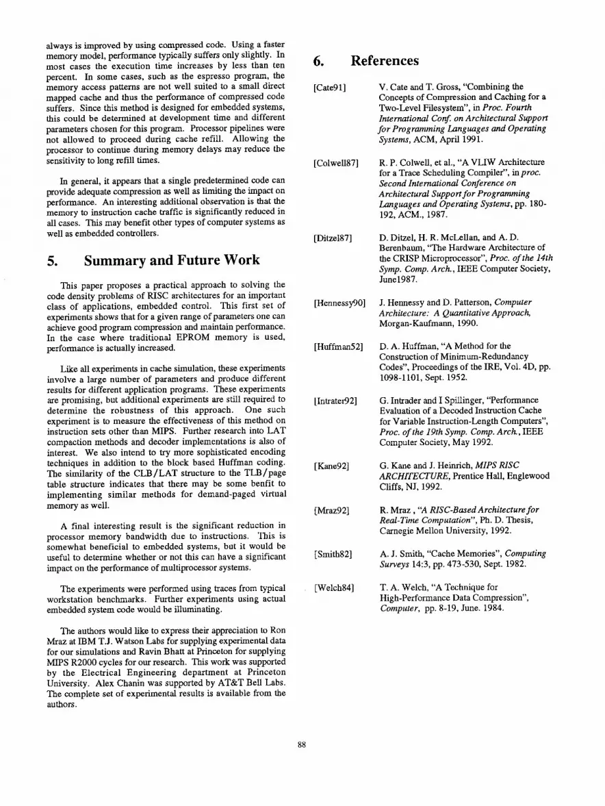
An exact analytical model of performance is quite difficult since the characteristics of each compressed cache line can differ. There is however a significant correlation between instruction cache miss rate and performance. Figure 9 plots most of the results from section 4.2.1. It is clear from this data that for slow memories, the compressed code model will outperform standard code more at higher miss rates while the opposite is true for faster memory.
4.2.4. Data cache effects
Many embedded processor systems operate without a data cache. It is useful, however, to estimate the effect that a data cache would have on the performance of a CCRP. A simple analytical model has been used to approximate this effect. Data cache hits are assumed to take no additional cycles. Data cache misses add 4 cycles per access. A miss rate is multiplied by the number of data accesses to predict the overall performance. The results of experiments on three programs are presented in tables 11 through 13. As the data cache miss rate increases, the effect of the CCRP on performance is reduced.
1.400 -,
0.600 1 __
0.600
0.400
O.*O” - 0.000 ! I
0.00% 2.00% 4.00% 6.00% 6.00% 10.00% 12.00% 14.00%
I x EPROM Model 0 Burst EPROM Model + DRAM Model I
Figure 9- Performance vs. Instruction Cache Miss Rate.
4.3. Conclusions
The experiments show that for the tested parameters and programs, the results are quite promising. Given a slow memory model like the EPROM model, performance almost
87
always is improved by using compressed code. Using a faster memory model, performance typically suffers only slightly. In most cases the execution time increases by less than ten percent. In some cases, such as the espresso program, the memory access patterns are not well suited to a small direct mapped cache and thus the performance of compressed code suffers. Since this method is designed for embedded systems, this could be determined at development time and different parameters chosen for this program. Processor pipelines were not allowed to proceed during cache refill. Allowing the processor to continue during memory delays may reduce the sensitivity to long refill times.
In general, it appears that a single predetermined code can provide adequate compression as well as limiting the impact on performance. An interesting additional observation is that the memory to instruction cache traftic is significantly reduced in all cases. This may benefit other types of computer systems as well as embedded controllers.
5. Summary and Future Work
This paper proposes a practical approach to solving the code density problems of RISC architectures for an important class of applications, embedded control. This first set of experiments shows that for a given range of parameters one can achieve good program compression and maintain performance. In the case where traditional EPROM memory is used, performance is actually increased.
Like all experiments in cache simulation, these experiments involve a large number of parameters and produce different results for different application programs. These experiments are promising, but additional experiments are still required to determine the robustness of this approach. One such experiment is to measure the effectiveness of this method on instruction sets other than MIPS. Further research into LAT compaction methods and decoder implementations is also of interest. We also intend to try more sophisticated encoding techniques in addition to the block based Huffman coding. The similarity of the CLB/LAT structure to the TLB/page table structure indicates that there may be some benfit to implementing similar methods for demand-paged virtual memory as well.
A final interesting result is the significant reduction in processor memory bandwidth due to instructions. This is somewhat beneficial to embedded systems, but it would be useful to determine whether or not this can have a significant impact on the performance of multiprocessor systems.
The experiments were performed using traces from typical workstation benchmarks. Further experiments using actual embedded system code would be illuminating.
The authors would like to express their appreciation to Ron Mraz at IBM T.J. Watson Labs for supplying experimental data for our simulations and Ravin Bhatt at Princeton for supplying MIPS R2000 cycles for our research. This work was supported by the Electrical Engineering department at Princeton University. Alex Chanin was supported by AT&T Bell Labs. The complete set of experimental results is available from the authors.
6. References
[Cate91]
[Colwell87]
[Ditze187]
[Hennes@O]
[Huffman
[Intratei92]
[ Kane921
[Mraz92]
[Smith82]
[Welch841
V. Cate and T. Gross, “Combining the Concepts of Compression and Caching for a Two-Level Filesystem”, in Proc. Fourth Internationai Co@ on Architectural Support for Programming Languages and Operating Systems, ACM, April 1991.
R. P. Colwell, et al., “A VLIW Architecture for a Trace Scheduling Compiler”, in proc. Second International Conference on Architectural Supportfor Programming Languages and Operating Systems, pp. 180- 192, ACM., 1987.
D. Ditzel, H. R. McLellan, and A. D. Berenbaum, “The Hardware Architecture of the CRISP Microprocessor”, Proc. of the 14th Symp. Comp. Arch., IEEE Computer Society, June1987.
J. Hennessy and D. Patterson, Computer Architecture: A Quantitative Approach, Morgan-Kaufmann, 1990.
D. A. Huffman, “A Method for the Construction of Minimum-Redundancy Codes”, Proceedings of the IRE, Vol. 4D, pp. 1098-1101, Sept. 1952.
G. Intrader and I Spillinger, “Performance Evaluation of a Decoded Instruction Cache for Variable Instruction-Length Computers”, Proc. of the 19th Symp. Comp. Arch., IEEE Computer Society, May 1992.
G. Kane and J. Heimich, MIPS RISC ARCHITECTURE, Prentice Hall, Englewood Cliffs, NJ, 1992.
R. Mraz , “A RISC-Based Architecture for Real-Time Computation”, Ph. D. Thesis, Carnegie Mellon University, 1992.
A. J. Smith, “Cache Memories”, Computing Surveys 14:3, pp. 473-530, Sept. 1982.
T. A. Welch, “A Technique for High-Performance Data Compression”, Computer, pp. 8-19, June. 1984.
88

NASA7 Cache Size Relative Cache Miss Memory Cache Size Relative Cache Miss Memory Performance Rate Traffic fPPPP
Performance Rate Traffic EPROM 256 bvte 0.976 5.13% 86.0% EPROM 256 byte 0.983 17.44% 67.1%
512 byte 0.984 15.85% 67.5%
1024 bvte 0.984 15.85% 67.5%
Table 1: NASA7 - 16 entry CLB, 100% Data Cache Miss Rate.
Matrix25A Cache Size Relative Cache Miss Memory Performance Rate Traffic
EPROM 256 byte 0.980 1.50% 68.1% 512 byte 0.983 1.24% 69.7%
1024 byte 0.994 0.47% 68.1% 2048 byte 0.994 0.43% 67.5% 4096 bvte 0.995 0.35% 66.8%
Burst EPROM 256 byte 1.038 1.50% 68.1% 512 byte 1.032 1.24% 69.7%
1024 byte 1.013 0.47% 68.1% 2048 bvte 1.012 0.43% 67.5%
4096 byte 1 1.010 1 0.35% 1 66.8% )
Table 2: Matrix25A- 16 entry CLB, 100% Data Cache Miss Rate.
2048 bvte 1 1.0001 0.01% I 79.3%1
4096 byte 1.000 0.01% 79.2% Burst EPROM 256 byte 1.029 17.44% 67.1%
512 bvte 1.026 15.85% 67.5%
1024 byte 1.026 15.85% 67.5%
2048 byte 1.000 0.01% 79.3%
4096 bvte 1.000 0.01% 79.2%
Table 3: fpppp- 16 entry CLB, 100% Data Cache Miss Rate.
espresso Cache Size Relative Cache Miss Memory Performance Rate Traffic
EPROM 256 byte 0.905 12.47% 79.0%
512 byte 0.918 9.87% 79.8%
1024 byte 0.931 8.01% 80.4%
2048 byte 0.941 6.42% 80.6%
4096 byte 0.957 3.96% 80.6% Burst EPROM 256 byte 1.323 12.47% 79.0%
512 byte 1.283 9.87% 79.8%
1024 bvte 1.249 8.01% 80.4%
2048 byte
4096 byte
1.213 6.42% 80.6%
1.147 3.96% 80.6%
Table 4: espresso- 16 entry CLB, 100% Data Cache Miss Rate.

1024 byte 0.998 0.24% 79.1% 2048 byte 0.998 0.23% 79.2% 4096 bvte 0.998 0.22% 79.6% .
Burst EPROM 256 byte 1.070 2.63% 82.0% 512 byte 1.022 0.76% 82.6%
1024 byte 1.007 0.24% 79.1% 2048 bvte 1.007 0.23% 79.2%
I 4096 bvte 1 1.007 I 0.22% I 79.6% 1
Table 5: NASAl- 16 entry CLB, 100% Data Cache Miss Rate.
eightq Cache Size Relative Cache Miss Memory Performance Rate Traffic
EPROM 256 byte 0.884 10.90% 68.3%
512 byte 0.995 0.27% 74.4% 1024 bvte 0.997 0.19% 76.4%
Table 6: eightq- 16 entry CLB, 100% Data Cache Miss Rate.
Table 7: tomcatv- 16 entry CLB, 100% Data Cache Miss Rate.
1100p01 Cache Size Relative Cache Miss Memory Performance Rate Traffk
EPROM 256 byte 0.994 0.36% 73.1%
512 byte 0.996 0.28% 72.4%
Table 8: lloopO1 - 16 entry CLB, 100% Data Cache Miss Rate.

Relative
NASA7 Cache Size Performance 16 CLB Entries
EPROM 256 byte 0.976
512 byte 0.977
1024 byte 0.982
2048 byte 0.988
4096 byte 0.991
Burst EPROM 256 byte 1.098
512 byte 1.077
1024 byte 1.068
t 4096 2048 byte byte 1 1 1.058 1.048
I-
Relative 1 Relative
Table 9: NASA7 - 100% Data Cache Miss Rate.
Table 10: espresso - 100% Data Cache Miss Rate.
NASA7 Icache Size Dcache Miss Relative Rate Performance
EPROM 1024 bvte 0% 0.963 d
1024 byte 2% 0.964
1024 byte 10% 0.966
1024 byte 25% 0.971
1024 byte 100% 0.982
Burst EPROM 1024 byte 0% 1.162
1024 byte 2% 1.158
1024 byte 10% 1.142
1024 byte 1 25% 1 1.120
1024 byte 1 100% 1 1.068
I
1024 byte 25% 1.072
1024 byte 100% 1.026
fPPPP Icache Size Dcache Miss Relative
Rate Performance
EPROM 1024 byte 0% 0.906
1024 bvte 2% 0.906
1024 byte 10% 0.909
1024 byte 25% 0.914
1024 byte 100% 0.93 1
Tables 11-13: Effect of Data Cache Miss Rate - 16 entry CLB.


