Embed Size (px)
Citation preview
SCIENCE CHINA Technological Sciences
© Science China Press and Springer-Verlag Berlin Heidelberg 2015 tech.scichina.com link.springer.com
*Corresponding author (email: [email protected])
• Article • March 2015 Vol.58 No.3: 1–9
doi: 10.1007/s11431-015-5772-9
Experimental and numerical investigation of failure mode in geometrically imperfect DP590 steel
ZHUANG XinCun, XU Cheng & ZHAO Zhen*
Institute of Forming Technology & Equipment, School of Materials Science and Engineering, Shanghai Jiaotong University, Shanghai 200030, China
Received November 3, 2014; accepted January 6, 2015
Various microstructure-level finite element models were generated according to the real microstructure of DP590 steel to cap-ture the mechanical behavior and fracture mode. The failure mode of the dual-phase (DP) steels, mainly resulting from micro-structure-level inhomogeneity and initial geometrical imperfection, was predicted using the plastic strain localization theory. In addition, dog-bone-type tensile test specimens with different edge qualities were prepared and the deformation processes were recorded using a digital image correlation system. When the steel exhibited no initial geometrical imperfection, void initiation was triggered by decohesion between martensite and ferrite which was predicted based on the severe strain concentration, or tensile stress in areas where stress triaxiality and strain values were high. Final failure was caused by shear localization in the vicinity. Moreover, the initial geometrical imperfections severely affected the overall ductility and failure mode of the DP590 steel. When initial geometrical imperfections were deeply ingrained, an incipient crack began at the site of initial geometrical imperfection, and then caused progressive damage throughout the microstructure, from the area of shear localization to the fi-nal fracture. Overall, the depth of the geometrical imperfection was the critical factor in determining whether internal decohe-sion or a local crack plays a dominant role.
representative volume element, dual-phase (DP) steel, geometrical imperfection, failure mode
Citation: Zhuang X C, Xu C, Zhao Z. Experimental and numerical investigation of failure mode in geometrically imperfect DP590 steel. Sci China Tech Sci, 2015, 58, doi: 10.1007/s11431-015-5772-9
1 Introduction
In the modern automotive industry, automobile body weight has been increasingly reduced by implementing new mate-rial-processing technologies and lightweight materials. The dual-phase (DP) steels with a microstructure consisting of a ferrite matrix, in which particles of martensite are dispersed, have received a substantial amount of attention because they are of high strength and feature a high work-hardening rate and ductility [1,2]. Therefore, they are suitable for use in the sheet metal forming processes. However, the DP steels eas-
ily develop edge cracks that complicate describing the fail-ure mode and predicting ductility during post-processing operations conducted using conventional procedures such as the forming limit diagram.
To investigate edge cracks, Sartkulvanich et al. [3] fo-cused on numerical modeling and experimented with the blanking and hole expansion of DP590 steel, characterizing the edge quality of various die clearances and demonstrating the effect that a sheared edge exerts on stretchability. Konieczny and Henderson [4] presented sheared-edge fail-ure modes for advanced high strength steel (AHSS) sub-jecting to various loading modes, and discussed the influ-ence of blanking clearance and edge morphology parame-ters on formability. Based on the experimental data, they
doi: 10.1007/s11431-015-5772-9
2 Zhuang X C, et al. Sci China Tech Sci March (2015) Vol.58 No.3
provided practical recommendations for edge preparation and clearance in blanking or hole-punching operations for numerous AHSSs. Similar studies [5] have indicated that edge cracks occur under obviously lower amounts of strain than the strain predicted using forming limit curve (FLC), and that the edge quality of a blanked hole considerably influences the forming limit. Wu et al. [6] characterized the mechanically sheared edges of DP steels using three die clearances (5%, 10%, and 15% of thickness) by using opti-cal microscopy and scanning electron microscopy, and ob-served the morphology and random features of the sheared edges. The results suggested that inhomogeneous micro-structures and the existence of two phases (martensite and ferrite), the properties of which differed notably, were cru-cial to the edge-shear fracture process. Upon failure, in-completely developed subcracks form “∧”-shaped surface cracks or sink patches in the burnish and fractured zones, creating initial geometrical imperfections during post-pro- cessing.
To determine the mechanical behaviors of multiphase materials, relevant studies have quantitatively correlated the microstructure and mechanical properties of the DP steels by using representative volume elements (RVEs). The ex-tent to which RVEs capture the behavior of microstructures depends on how accurately they describe the morphological features of the microstructures [7]. Thus, several idealiza-tions have been investigated, and the axisymmetric model can be used to capture the expected material behavior [8]. Hosseini-Toudeshky et al. [9] evaluated the deformation pattern and mechanical behavior by using large and small deformation theories and a microstructure-based RVE. They determined that accurately predicting stress-strain behavior depended on considering the large deformation theory dur-ing analysis. Ramazani et al. [10] imposed periodic and homogeneous boundary conditions to obtain stress-strain curves based on the microstructure-based RVE calculations, and observed that implementing the periodic boundary con-dition in the smaller RVEs resulted in closer values to the converged effective value.
Typically, DP steels possess a combination of ductile fracture (dimple) and cleavage fracture modes, albeit the ductile fracture is the dominant mode. Loss of uniform de-formation when simple tension is applied to plastic materi-als relates to the attainment of the peak nominal stress, and subsequent strain localization leading to ductile fracture can be treated as the loss of stability in uniform deformation. Therefore, the mechanism of ductile fracture is a cusp ca-tastrophe, and the ultimate ductility of the material depends on the damage evolution that occurs at the post-bifurcation stage [11]. Accordingly, the classical Marciniak-Kucaynski model [12] having initial geometrical imperfections that trigger instability [13,14] is used to predict the localized necking , and the damage- and void-growth-induced bifur-cation condition in the popular Gurson-Tvergaard-Needle- man (GTN) model can be analytically formulated as materi-
al instability occurring on a constitutive level [15]. Uthaisangsuk et al. [16–18], Vajragupta et al. [19], and Ramazani et al. [20] used the microstructure-based RVEs to evaluate microstructure deformation and failure initiation from the mesoscale, addressing martensite cracking using an extended finite element method (XFEM). In addition, a cohesive zone model was used to study the debonding anal-ysis of the martensite islands in the ferrite parent phase, and the GTN model was used to describe the ductile damage of the ferrite matrix. By contrast, material microstructure-level inhomogeneity [21] is another source of initial imperfection triggering the plastic instability of DP steels [22–24]. RVEs have been employed to predict the flow behavior, plastic strain localization, and plastic instability of steel under var-ious boundary conditions during uniaxial tensile loading.
In the present study, concentrations were placed on the effect of initial geometrical imperfections and material mi-crostructure-level inhomogeneity to trigger plastic instabil-ity rather than material instability on the constitutive level. A micromechanical model based on a real microstructure was developed to capture the mechanical behavior of DP590 steel. Since crack normally occurs soon after the appearance of strain localization according to the work of Sun et al. [22,23] and Paul [24], the failure mode was pre-dicted using the plastic strain localization theory in the pre-sented work. Although crack initiation and propagation could not be clearly presented, the potential crack incipient location and propagation path could be well captured through the plastic strain localization. Accordingly, dog- bone-type tensile test specimens with different edge quali-ties were prepared using an internally designed blanking tool, and the deformation processes were recorded using a digital image correlation (DIC) system. The results of ex-periments and simulations were correlated to gain insights regarding initial geometrical imperfections and material microstructure-level inhomogeneity that triggers plastic instability. The overall ductility of DP590 steel strongly depended on the ductility of the ferrite matrix, and preex-isting edge cracks that were initial geometrical imperfec-tions reduced the overall ductility of the steel and changed the failure mode.
2 Micromechanical modeling of DP590 steel
Micromechanical modeling using a numerical tensile test of an RVE is appropriate for use in studying and modeling the mechanical and failure behaviors of DP steel. This method provides a detailed description of the material deformation on the micro-level, offering insight into the stress and strain evolution and distribution in and between the phases.
2.1 Representative volume element generation
The 2D RVE model built in this study was based on a real
Zhuang X C, et al. Sci China Tech Sci March (2015) Vol.58 No.3 3
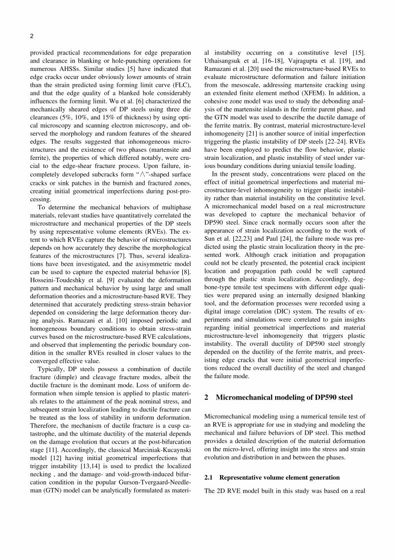
microstructure picture of DP590 steel. To obtain a light op-tical microscopy image of the steel, specimens were pre-pared by using a series of polishing and short etching treat-ments (5–7 s) in which 2% nital was applied. The etchant lepera (consisting of a 1% aqueous solution of sodium metabisulfite and 4% picric acid in ethyl alcohol) was mixed, after which the specimens were immersed in the lepera for 7–12 s at room temperature. The specimens were then rinsed with ethyl alcohol and blown dry until their sur-faces appeared blue-orange. According to the work of Lep-era [25], with the current etchant martensitic grains appear white and ferrite appears tan, but in most cases the grain boundaries are not strongly etched. Under the light optical microscope, same phenomenon could be found as shown in Figure 1(a).
To mesh the DP590 microstructure, an image of DP590 steel was first automatically segmented into two phases by using the photo-processing software Photoshop. Segmenta-tion could be performed by adjusting the contrast and colors until all martensite grains appeared white and all ferrite grains appeared black. Since the boundaries were not strongly etched, here only the original white grains were defined as martensite and the others as ferrite. Lines defin-ing the boundaries between the two phases were then gen-erated using the same software. The boundary-line image was imported into AlgoLab and converted from raster to vector form. The image was subsequently converted to a 2D ABAQUS/Explicit model (Figure 1(b)) by using Hy-permesh software to mesh the selected region with com-bined triangular and rectangular elements. A mesh size of 0.3 μm was used for both the martensite and ferrite regions. According to Ramazani et al. [10], RVEs size greater than 24 μm converge to an effective value in equiaxed and banded microstructures. Therefore, in this study the size of the 2D RVE was 55 μm× 55 μm and the total element number was 39852.
Since the failure mode was predicted using the plastic strain localization theory in the presented work, no fracture criteria whatever ductile fracture criteria or cohesive zone model were adopted. The boundaries of ferrite and marten-site in this study were perfectly connected, i.e. the nodes at the boundaries were shared. The appearance of decohesion
Figure 1 RVE generation. (a) Real microstructure; (b) RVE model.
between ferrite and martensite was determined by the oc-currence of severe strain concentration in the ferrite domain adjacent to the boundary of ferrite and martensite area.
The effect of volume fraction of the harder phase (mar-tensite) has been investigated by different authors [20,22,26,27]. High volume fraction of the martensite phase generally increases the yield and ultimate strengths of the DP steel, meanwhile reduces the ductility. Pointing at this topic, the image manipulation method mentioned above may influence the numerical simulation accuracy. However, for the currently presented work the failure mode in geo-metrically imperfect DP590 steel was mainly focused on, while the influence of different martensite fractions on the final ductility and failure mode was not emphasized. By simply conducting image processing, the calculated marten-site fraction was 22% and approximately equaled the vol-ume fraction of the martensite measured in the experiments. The following simulation work was performed based on the same processed microstructure.
2.2 Selection of boundary condition
Generally, 2D generalized plane strain loading conditions, in which the constraints in the z direction are between those of the plane stress and the plane strain loading conditions, are the most appropriate for use in comparing the simulation results with actual uniaxial test data obtained from cylindri-cal specimens [28,29]. The sheet specimens tested in this study were relatively thin compared with their in-plane di-mensions and were subjected to in-plane loading during uniaxial tensile tests. Therefore, the sheet specimens were under a condition of plane stress. Hybrid 2D plane stress CPS4R and CPS3 elements were adopted to simulate the in-plane failure modes of DP590 sheet steel under tensile loading.
Because RVEs were generated from the microstructure level, the periodic boundary condition [30] could be applied to the calculations, and the entire macroscopic specimen could have been reconstructed by spatially repeating RVE. However, the homogeneous boundary condition (Figure 2) could also have been implemented to create a situation close to that during the real tensile test (i.e., all the nodes along the right edge were assigned the same displacements in the
Figure 2 Schematic representation of the homogeneous boundary condi-tions.
4 Zhuang X C, et al. Sci China Tech Sci March (2015) Vol.58 No.3
x direction and could freely move in the y direction during tensile loading, and all the nodes along the left edge were restricted from moving in the x direction, but were allowed to freely move in the y direction). In the current study, be-cause the initial geometrical imperfections and material microstructure-level inhomogeneity triggering plastic insta-bility were investigated simultaneously, a homogeneous boundary condition was established for use in the remainder of the study.
2.3 Determination of mechanical properties of the two phases
An empirical model [31] was applied to describe the strain-hardening behavior of the individual phases in DP590 steel, in which various parameters were computed according to the local chemical composition. The approach is ex-pressed in eq. (1) below.
r p0
r
1 exp( ),
MkM b
k L
(1)
where is a constant; M is a Taylor factor (M=3); is the shear modulus (=80000 MPa); b is the Burger’s vector (b=2.5×10¹⁰ m); L is the dislocation mean free path (for ferrite L=5.0×10⁶ m and for martensite L=3.8×10⁸ m); kr is the recovery rate (kr=1.1 and 41 for ferrite and martensite, respectively); and 0 is the yield strength, calculated based on the chemical composition (in the DP590 steel, for ferrite 0=376 MPa and for martensite 0= 1279 MPa).
3 Experiments
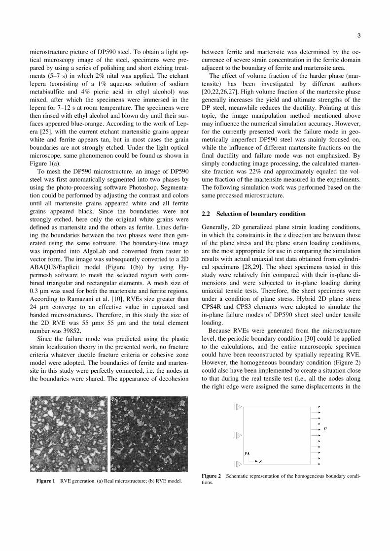
To evaluate the role the initial geometrical imperfection plays in triggering plastic instability, dog-bone-type tensile test specimens with different edge qualities were prepared
using an internally designed blanking tool (Figure 3). The specimen material was DP590 cold rolling steel with a thickness of 1.8 mm. The specimens were first prepared by wire cutting a rectangular shape, and then the area delineat-ed by the dotted line was blanked, achieving the required gauge length feature. Three clearances were designed to obtain various edge qualities. They were 5.65%, 16.67%, and 27.78% of thicknesses. In addition, a wire-cutting method was adopted to produce the gauge length feature as well.
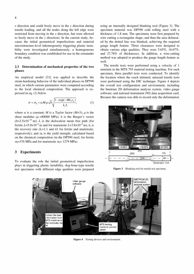
The tensile tests were performed using a velocity of 1 mm/min in the MTS 793 material testing machine. For each specimen, three parallel tests were conducted. To identify the location where the crack initiated, uniaxial tensile tests were performed using the DIC technique. Figure 4 depicts the overall test configuration and environment, including the Imetrum 2D deformation analysis system, video gauge software, and national instrument (NI) data acquisition card. Because the camera was able to record only the deformation
Figure 3 Blanking tool for tensile test specimen.
Figure 4 Testing devices and environment.
Zhuang X C, et al. Sci China Tech Sci March (2015) Vol.58 No.3 5
and the displacement information, the load information was collected using the NI data acquisition card and subse-quently transferred to the video gauge software. The soft-ware was used to synchronize the signals of load and dis-placement, which were eventually transformed into the force-displacement curve.
In addition, to validate the measurement, the extensome-ter was used during the experiments, and the resulting curve was compared with the curve measured using the Imetrum 2D deformation analysis system. The results obtained in a previous study [32] indicated that the Imetrum system could capably replace or perform the function of the extensometer. By using the Imetrum system, the gauge length of the specimen could be dynamically set based on the recorded video, even after the material test had been completed.
4 Results and discussion
4.1 Macroscopic failure mode under various conditions
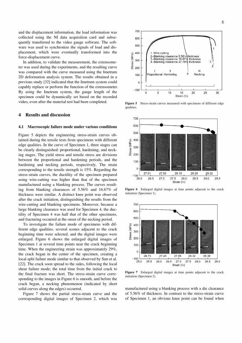
Figure 5 depicts the engineering stress-strain curves ob-tained during the tensile tests from specimens with different edge qualities. In the curve of Specimen 1, three stages can be clearly distinguished: proportional, hardening, and neck-ing stages. The yield stress and tensile stress are divisions between the proportional and hardening periods, and the hardening and necking periods, respectively. The strain corresponding to the tensile strength is 15%. Regarding the stress-strain curves, the ductility of the specimen prepared using wire-cutting was higher than that of the specimen manufactured using a blanking process. The curves result-ing from blanking clearances of 5.56% and 16.67% of thickness were similar. A distinct knee point was observed after the crack initiation, distinguishing the results from the wire-cutting and blanking specimens. Moreover, because a large blanking clearance was used for Specimen 4, the duc-tility of Specimen 4 was half that of the other specimens, and fracturing occurred at the onset of the necking period.
To investigate the failure mode of specimens with dif-ferent edge qualities, several scenes adjacent to the crack beginning time were selected, and the digital images were enlarged. Figure 6 shows the enlarged digital images of Specimen 1 at several time points near the crack beginning time. When the engineering strain was approximately 29%, the crack began in the center of the specimen, creating a local split failure mode similar to that observed by Sun et al. [22]. The crack soon spread to the sides, following the local shear failure mode; the total time from the initial crack to the final fracture was short. The stress-strain curve corre-sponding to the images in Figure 6 is smooth, and before the crack began, a necking phenomenon (indicated by short solid curves along the edges) occurred.
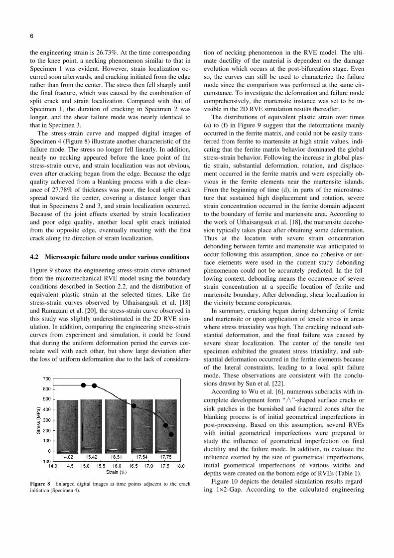
Figure 7 shows the partial stress-strain curve and the corresponding digital images of Specimen 2, which was
Figure 5 Stress-strain curves measured with specimens of different edge qualities.
Figure 6 Enlarged digital images at time points adjacent to the crack initiation (Specimen 1).
Figure 7 Enlarged digital images at time points adjacent to the crack initiation (Specimen 2).
manufactured using a blanking process with a die clearance of 5.56% of thickness. In contrast to the stress-strain curve of Specimen 1, an obvious knee point can be found when
6 Zhuang X C, et al. Sci China Tech Sci March (2015) Vol.58 No.3
the engineering strain is 26.73%. At the time corresponding to the knee point, a necking phenomenon similar to that in Specimen 1 was evident. However, strain localization oc-curred soon afterwards, and cracking initiated from the edge rather than from the center. The stress then fell sharply until the final fracture, which was caused by the combination of split crack and strain localization. Compared with that of Specimen 1, the duration of cracking in Specimen 2 was longer, and the shear failure mode was nearly identical to that in Specimen 3.
The stress-strain curve and mapped digital images of Specimen 4 (Figure 8) illustrate another characteristic of the failure mode. The stress no longer fell linearly. In addition, nearly no necking appeared before the knee point of the stress-strain curve, and strain localization was not obvious, even after cracking began from the edge. Because the edge quality achieved from a blanking process with a die clear-ance of 27.78% of thickness was poor, the local split crack spread toward the center, covering a distance longer than that in Specimens 2 and 3, and strain localization occurred. Because of the joint effects exerted by strain localization and poor edge quality, another local split crack initiated from the opposite edge, eventually meeting with the first crack along the direction of strain localization.
4.2 Microscopic failure mode under various conditions
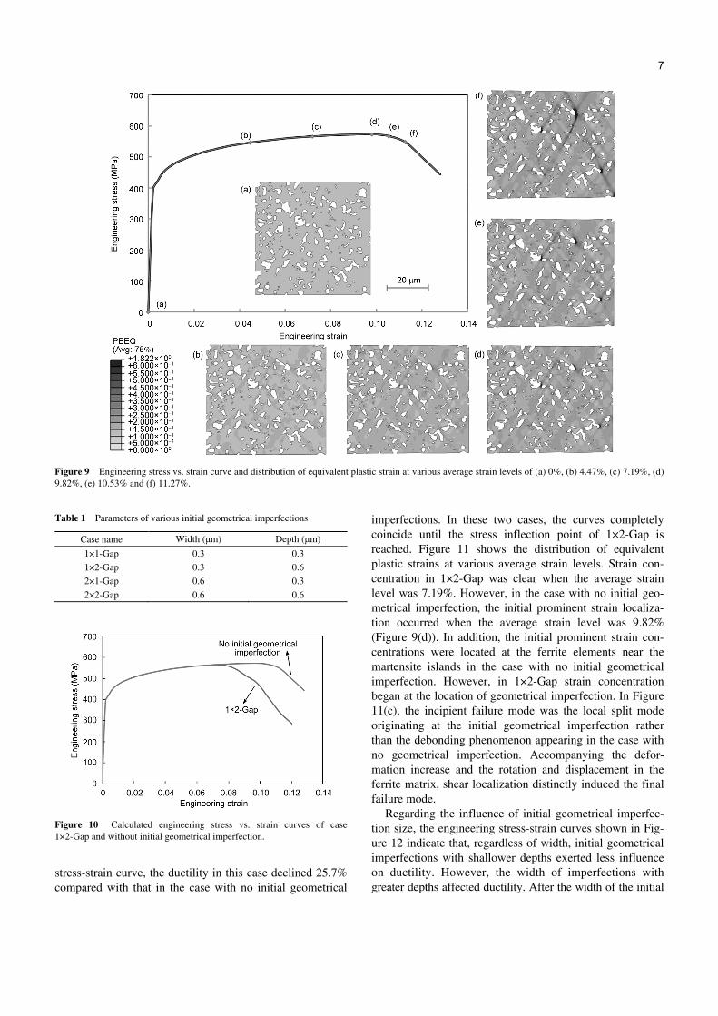
Figure 9 shows the engineering stress-strain curve obtained from the micromechanical RVE model using the boundary conditions described in Section 2.2, and the distribution of equivalent plastic strain at the selected times. Like the stress-strain curves observed by Uthaisangsuk et al. [18] and Ramazani et al. [20], the stress-strain curve observed in this study was slightly underestimated in the 2D RVE sim-ulation. In addition, comparing the engineering stress-strain curves from experiment and simulation, it could be found that during the uniform deformation period the curves cor-relate well with each other, but show large deviation after the loss of uniform deformation due to the lack of considera-
Figure 8 Enlarged digital images at time points adjacent to the crack initiation (Specimen 4).
tion of necking phenomenon in the RVE model. The ulti-mate ductility of the material is dependent on the damage evolution which occurs at the post-bifurcation stage. Even so, the curves can still be used to characterize the failure mode since the comparison was performed at the same cir-cumstance. To investigate the deformation and failure mode comprehensively, the martensite instance was set to be in-visible in the 2D RVE simulation results thereafter.
The distributions of equivalent plastic strain over times (a) to (f) in Figure 9 suggest that the deformations mainly occurred in the ferrite matrix, and could not be easily trans-ferred from ferrite to martensite at high strain values, indi-cating that the ferrite matrix behavior dominated the global stress-strain behavior. Following the increase in global plas-tic strain, substantial deformation, rotation, and displace-ment occurred in the ferrite matrix and were especially ob-vious in the ferrite elements near the martensite islands. From the beginning of time (d), in parts of the microstruc-ture that sustained high displacement and rotation, severe strain concentration occurred in the ferrite domain adjacent to the boundary of ferrite and martensite area. According to the work of Uthaisangsuk et al. [18], the martensite decohe-sion typically takes place after obtaining some deformation. Thus at the location with severe strain concentration debonding between ferrite and martensite was anticipated to occur following this assumption, since no cohesive or sur-face elements were used in the current study debonding phenomenon could not be accurately predicted. In the fol-lowing context, debonding means the occurrence of severe strain concentration at a specific location of ferrite and martensite boundary. After debonding, shear localization in the vicinity became conspicuous.
In summary, cracking began during debonding of ferrite and martensite or upon application of tensile stress in areas where stress triaxiality was high. The cracking induced sub-stantial deformation, and the final failure was caused by severe shear localization. The center of the tensile test specimen exhibited the greatest stress triaxiality, and sub-stantial deformation occurred in the ferrite elements because of the lateral constraints, leading to a local split failure mode. These observations are consistent with the conclu-sions drawn by Sun et al. [22].
According to Wu et al. [6], numerous subcracks with in-complete development form “∧”-shaped surface cracks or sink patches in the burnished and fractured zones after the blanking process is of initial geometrical imperfections in post-processing. Based on this assumption, several RVEs with initial geometrical imperfections were prepared to study the influence of geometrical imperfection on final ductility and the failure mode. In addition, to evaluate the influence exerted by the size of geometrical imperfections, initial geometrical imperfections of various widths and depths were created on the bottom edge of RVEs (Table 1).
Figure 10 depicts the detailed simulation results regard-ing 1×2-Gap. According to the calculated engineering
Zhuang X C, et al. Sci China Tech Sci March (2015) Vol.58 No.3 7
Figure 9 Engineering stress vs. strain curve and distribution of equivalent plastic strain at various average strain levels of (a) 0%, (b) 4.47%, (c) 7.19%, (d) 9.82%, (e) 10.53% and (f) 11.27%.
Table 1 Parameters of various initial geometrical imperfections
Case name Width (μm) Depth (μm)
1×1-Gap 0.3 0.3 1×2-Gap 0.3 0.6 2×1-Gap 0.6 0.3 2×2-Gap 0.6 0.6
Figure 10 Calculated engineering stress vs. strain curves of case 1×2-Gap and without initial geometrical imperfection.
stress-strain curve, the ductility in this case declined 25.7% compared with that in the case with no initial geometrical
imperfections. In these two cases, the curves completely coincide until the stress inflection point of 1×2-Gap is reached. Figure 11 shows the distribution of equivalent plastic strains at various average strain levels. Strain con-centration in 1×2-Gap was clear when the average strain level was 7.19%. However, in the case with no initial geo-metrical imperfection, the initial prominent strain localiza-tion occurred when the average strain level was 9.82% (Figure 9(d)). In addition, the initial prominent strain con-centrations were located at the ferrite elements near the martensite islands in the case with no initial geometrical imperfection. However, in 1×2-Gap strain concentration began at the location of geometrical imperfection. In Figure 11(c), the incipient failure mode was the local split mode originating at the initial geometrical imperfection rather than the debonding phenomenon appearing in the case with no geometrical imperfection. Accompanying the defor-mation increase and the rotation and displacement in the ferrite matrix, shear localization distinctly induced the final failure mode.
Regarding the influence of initial geometrical imperfec-tion size, the engineering stress-strain curves shown in Fig-ure 12 indicate that, regardless of width, initial geometrical imperfections with shallower depths exerted less influence on ductility. However, the width of imperfections with greater depths affected ductility. After the width of the initial
8 Zhuang X C, et al. Sci China Tech Sci March (2015) Vol.58 No.3
Figure 11 Distribution of equivalent plastic strain for the case of 1×2-Gap at various average strain levels of (a) 0%, (b) 7.19% and (c) 8.46%.
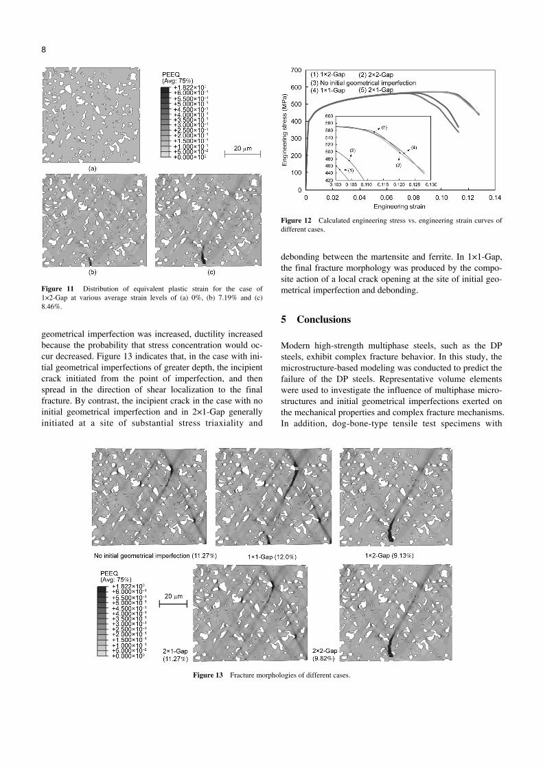
geometrical imperfection was increased, ductility increased because the probability that stress concentration would oc-cur decreased. Figure 13 indicates that, in the case with ini-tial geometrical imperfections of greater depth, the incipient crack initiated from the point of imperfection, and then spread in the direction of shear localization to the final fracture. By contrast, the incipient crack in the case with no initial geometrical imperfection and in 2×1-Gap generally initiated at a site of substantial stress triaxiality and
Figure 12 Calculated engineering stress vs. engineering strain curves of different cases.
debonding between the martensite and ferrite. In 1×1-Gap, the final fracture morphology was produced by the compo-site action of a local crack opening at the site of initial geo-metrical imperfection and debonding.
5 Conclusions
Modern high-strength multiphase steels, such as the DP steels, exhibit complex fracture behavior. In this study, the microstructure-based modeling was conducted to predict the failure of the DP steels. Representative volume elements were used to investigate the influence of multiphase micro-structures and initial geometrical imperfections exerted on the mechanical properties and complex fracture mechanisms. In addition, dog-bone-type tensile test specimens with
Figure 13 Fracture morphologies of different cases.
Zhuang X C, et al. Sci China Tech Sci March (2015) Vol.58 No.3 9
different preexisting edge qualities in the area of gauge sec-tion were prepared using an internally designed blanking tool, and the corresponding uniaxial tensile test procedures were recorded using a digital image correlation system. By bridging the observations from microscopic and macro-scopic viewpoints, the following conclusions were drawn.
(1) During the necking and localization procedure of the DP steel, substantial deformation, rotation, and displace-ment occurred in the ferrite matrix. Thus, the overall ductil-ity of DP590 steel depended on the ductility of the ferrite matrix.
(2) In the case with no initial geometrical imperfection, cracking began with the occurrence of debonding predicted based on the appearance of strain concentration or when tensile stress was exerted, creating areas where stress triaxi-ality and deformation values were high. Final failure was caused by severe shear localization. Similar conclusions can also be drawn based on the uniaxial tensile tests.
(3) The preexisting edge cracks or initial geometrical imperfections severely influenced the overall ductility of the DP steel and the failure mode. In cases with initial geomet-rical imperfections that had greater depths, the incipient crack initiated from the point of initial geometrical imper-fection and induced a progression of damage throughout the microstructure along the direction of shear localization to the final fracture.
(4) Relative to the geometrical imperfection width, the geometrical imperfection depth was a leading factor deter-mining whether the internal debonding effect or the local cracking effect exerted more influence.
This work was supported by the National Natural Science Foundation of China (Grant No. 51105250).
1 Rashid M S. GM 980X–a unique high strength sheet steel with supe-rior formability. SAE Technical Paper 760206, Society of Automo-tive Engineers, Warrendale, PA. 1976
2 Rashid M S, Cprek E R. Relationship between microstructure and formability in two high-strength, low-alloy steels. In: ASTM Special Technical Publication 647, ASTM, Philadelphia, PA, 1976: 174–190
3 Sartkulvanich P, Kroenauer B, Golle R, et al. Finite element analysis of the effect of blanked edge quality upon stretch flanging of AHSS. CIRP Ann-Manuf Techn, 2010, 59: 279–282
4 Konieczny A, Henderson T. On formability limitations in stamping involving sheared edge stretching. SAE Technical Paper 2007-01-0340, doi:10.4271/2007-01-0340
5 Wiedenmann R, Sartkulvanich P, Altan T. Finite element analysis on the effect of sheared edge quality in blanking upon hole expansion of advanced high strength steel. IDDRG 2009, Golden, CO, USA, 2009: 559–570
6 Wu X, Bahmanpour H, Schmid K. Characterization of mechanically sheared edges of dual phase steels. J Mater Process Tech, 2012, 212: 1209–1224
7 Socrate S, Boyce M C. Micromechanics of toughened polycarbonate. J Mech Phys Solids, 2000, 48: 233–273
8 Al-Abbasi F M, Nemes J A. Micromechanical modeling of dual phase steels. Int J Mech Sci, 2003, 45: 1449–1465
9 Hosseini-Toudeshky H, Anbarlooie B, Kadkhodapour J, et al. Micro-structure deformation pattern and mechanical behavior analyses of
DP600 dual phase steel. Mater Sci Eng A, 2014, 600: 108–121 10 Ramazani A, Mukherjee K, Prahl U, Bleck W. Modelling the effect
of microstructural banding on the flow curve behavior of dual-phase (DP) steels. Comp Mater Sci, 2012, 52: 46–54
11 Li Y, Karr D G. Prediction of ductile fracture in tension by bifurca-tion, localization, and imperfection analysis. Int J Plasticity, 2008, 25: 1128–1153
12 Marciniak Z, Kuczynski K. Limit strains in the processes of stretch-forming sheet metal. Int J Mech Sci, 1967, 9: 609–612
13 Aretz H. Numerical analysis of diffuse and localized necking in or-thotropic sheet metals. Int J Plasticity, 2007, 23: 798–840
14 Aretz H. A simple isotropic-distortional hardening model and its ap-plication in elastic-plastic analysis of localized necking in orthotropic sheet metals. Int J Plasticity, 2008, 24: 1457–1480
15 Sanchez P J, Huespe A E, Oliver J. On some topics for the numerical simulation of ductile fracture. Int J Plasticity, 2008, 24: 1008–1038
16 Uthaisangsuk V, Prahl U, Bleck W. Micromechanical modeling of damage behavior of multiphase steels. Comp Mater Sci, 2008, 43: 27–35
17 Uthaisangsuk V, Prahl U, Bleck W. Stretch-flangeability characteri-sation of multiphase steel using a microstructure based failure mod-eling. Comp Mater Sci, 2009, 45: 617–623
18 Uthaisangsuk V, Muenstermann S, Prahl U, et al. A study of mi-crocrack formation in multiphase steel using representative volume element and damage mechanics. Comp Mater Sci, 2011, 50: 1225–1232
19 Vajragupta N, Uthaisangsuk V, Schmaling B, et al. A micromechan-ical damage simulation of dual phase steels using XFEM. Comp Ma-ter Sci, 2012, 54: 271–279
20 Ramazani A, Schwedt A, Aretz A, et al. Characterization and model-ling of failure initiation in DP steel. Comp Mater Sci, 2013, 75: 35–44
21 Chatzigeorgiou G, Charalambakis N. Instability analysis of non-homogeneous materials under biaxial loading. Int J Plasticity, 2005, 11: 949–970
22 Sun X, Choi K S, Soulami A, et al. On key factors influencing ductile fractures of dual phase (DP) steels. Mater Sci Eng A, 2009, 526: 140–149
23 Sun X, Choi K S, Liu W N, et al. Predicting failure modes and ductil-ity of dual phase steels using plastic strain localization. Int J Plasticity, 2009, 25: 1888–1909.
24 Paul S K. Micromechanics based modeling of dual phase steels: Pre-diction of ductility and failure modes. Comp Mater Sci, 2012, 56: 34–42
25 LePera F S. Improved etching technique for the determination of percent martensite in high-strength dual-phase steels. Metallography, 1979, 12: 263–268
26 Jiang Z H, Guan Z Z, Lian J S. The relationship between ductility and material parameters for dual phase steel. J Mater Sci, 1993, 28: 1814–1818
27 Bag A, Ray K K, Dwarakadasa E S. Influence of martensit content and morphology on tensile and impact properties of high-martensite dual-phase steels. Metall Mater Trans, 1999, 30: 1193–1202.
28 Grujicic M, Erturk T, Owen W S. A finite element analysis of the ef-fect of the accommodation strains in the ferrite phase on the work hardening of a dual-phase steel. Mater Sci Eng, 1986, 82: 151–159
29 Ilie D E, O’Donnel B P, McGarry J P, et al. Computational modeling of the extrusion of an Al-SiC metal matrix composite using mac-roscale and microscale methods. J Strain Anal Eng, 2007, 42: 237–252
30 Kouznetsova V G. Computational homogenization for the multi-scale analysis of multiphase materials. Dissertation of Doctor Degree. Technical University Eindhoven, 2002
31 Rodriguez R M, Gutierrez I. Unified formulation to predict the tensile curves of steels with different microstructures. Mater Sci Forum, 2003, 426–432: 4525–4530
32 Zheng H, Wu Y J, Diao K S, et al. Experimental investigation of sheared edge’s influence on tensile properties of DP steel (in Chi-nese). J Shanghai Jiaotong Univ, 2014, 48: 405–411


