Embed Size (px)
Citation preview
�����������������
Citation: Gołebski, R. Experimental
Method of Machining Gears with an
Involute Profile Using CNC Lathe
with Driven Tools. Materials 2022, 15,
1077. https://doi.org/10.3390/
ma15031077
Academic Editor: Luca Sorrentino
Received: 26 December 2021
Accepted: 27 January 2022
Published: 29 January 2022
Publisher’s Note: MDPI stays neutral
with regard to jurisdictional claims in
published maps and institutional affil-
iations.
Copyright: © 2022 by the author.
Licensee MDPI, Basel, Switzerland.
This article is an open access article
distributed under the terms and
conditions of the Creative Commons
Attribution (CC BY) license (https://
creativecommons.org/licenses/by/
4.0/).
materials
Article
Experimental Method of Machining Gears with an InvoluteProfile Using CNC Lathe with Driven ToolsRafał Gołebski
Department Technology and Automation, Czestochowa University of Technology, Al. Armii Krajowej 21,42-200 Czestochowa, Poland; [email protected]
Abstract: There are many ways of machining gears; the world’s manufacturers of machine toolshave patented many methods that allow for the production of gears in an accurate and efficientway. In general, the patented methods require the use of kinematically complex and expensiveCNC machine tools. These tools, moreover, the production of the technology itself, including themachining code, require the use of dedicated software. Therefore, it seems justified to strive for theapplication of kinematically simple and relatively cheap machines in the machining processes so as toincrease the universality and availability of new machining methods. This paper presents a methodof machining a spur gear with straight teeth with an involute profile using a basic CNC lathe DMGMORI CLX350V4 equipped with driven tools. On the basis of the presented mathematical model, analgorithm was developed to generate a code that controls the machining of cylindrical gears withan involute profile of straight teeth, with the possibility of modifying the transition profile and thetooth root. The machining was experimental, and the gear was made of aluminium AlSi1MgMnusing a solid carbide cylindrical cutter. In conclusion, the presented method was found to be verycompetitive with commercial methods and is able to provide very high quality gears. The accuracyof the machined profile form deviation in the entire processing did not exceed an average value of10 µm; while assessing the tooth line, the basis average error was 5 µm. Finally, the gear was assessedas manufactured in accuracy class 6. This machining method guarantees very competitive machiningcycle times, and thanks to the use of an uncomplicated CNC lathe and universal tools, it providesgreat flexibility, at the same time giving the possibility of machining gears with arbitrary profiles.
Keywords: CNC machining; driven tools; involute; lathe; outline; roughness; spur gear; surfaceintegrity parameters
1. Introduction
Gear transmissions and their applications gained more and more importance at theturn of the 18th and 19th centuries. It was also during this period that more theoreticalstudies of tooth theory began to appear; in 1765, Leonard Euler published his work witha mathematical description of the meshing of two gears, treating the problem for a gearthat moves uniformly without friction, as described in this study by Radzevich [1]. Thepresented assumptions could then be met only by gears with involute or epicycloid toothcontours. Euler, only in theory, presented the methods of constructing a tooth profile asthe exact and approximate methods; however, his development was never used in theconstruction of the first machine for cutting teeth, which was pointed out by Litvin [2]. Theconstructors of the gears were then struggling with problems that are very current, but ona smaller scale: what is the most adequate profile of the mating teeth for a given situation,how to build a gear that can transfer a constant speed, and how to make the gear with teethas accurately as possible for a given profile. Brown [3] developed an application patentmethod of gear machining and designed the tool, a disk cutter. The patented technologyconsisted of mapping the shape of the cutting edge of the tool to the outline of the machinedtooth. The disadvantage of the method is the low level of accuracy depending on the shape
Materials 2022, 15, 1077. https://doi.org/10.3390/ma15031077 https://www.mdpi.com/journal/materials
Materials 2022, 15, 1077 2 of 19
of the tool contour, which is subject to constant wear during machining, and the lack ofversatility of the method; each set of tools can be used to machine a gear with a constantmodule. The advantage of the method is that it can be used on simple, non-complicatedmachine tools. This machining method is still used today.
Along with the intensive development of CNC machine tools and cutting tools at theend of the 20th century, many innovative solutions in the field of gear machining havebeen developed. An American patent developed by Scherbarth [4] presents a method ofmachining gears on numerically controlled machine tools. The tool used in this process is amilling disk cutter with replaceable inserts. When milling a tooth profile, the milling axisis positioned on a plane perpendicular to the tooth flank to be machined, and the cuttinginserts rotate in an angular range encompassing all the surfaces normal to the tooth profile.The tool is not geometrically related to the contour of the machined tooth. This processingmethod, known as invo-milling, is very efficient, but requires the use of a kinematicallycomplex machine tool. In the development of his patent, Vogel [5] presented a methodof machining gears using a conical tool with a hyperbolical profile, using numericallycontrolled machine tools simultaneously in five axes. The machining of the spaces betweenthe teeth is carried out through the envelope of the successive positions of the cutter blades.According to this method, many geometrical variants of gears can be processed, includinginternal gears. The power-skiving method requires use of a special tool, geometricallyadapted to the applied machining kinematics. The developed patent was an excellentbasis for the further development of the method, as evidenced by subsequent studies byHarmut et al. [6] and Sture [7] covering issues with the development of the geometry ofcutting inserts in tools used for machining. The new machining methods also had a greatinfluence on the development of the geometrical aspects of gear design. Litvin et al. [8]developed a solution that improved the gear drive of the helical or spur types comprisinga driving gear with a tooth surface that is uniquely double crowned in the profile andlongitudinal directions and a driven gear provided with a conjugated tooth surface thatcan comprise a conventional involute type tooth surface or a uniquely modified toothsurface. Guttman et al. [9] presented a solution for elliptical modification of the toothroot; such solutions are now quite often used in gear constructions. The works of manyother inventors included both issues related to the machining method and theoreticaldescriptions modifying the geometry of the tooth itself. Budzik et al. [10] presented amethod of manufacturing gear by incremental processing and then by subtractive methods,giving the geometry of the gear its final shape. Due to the method used, the gear wheelin the invention has a reduced mass while maintaining a high stiffness. Buseler [11] alsopresented a method of constructing a gear with a reduced mass and increased stiffness;the proposed solution was also characterized by a very high susceptibility of the structureto vibration damping. Kostron et al. [12] presented a solution of a hybrid tooth profile inwhich the tooth head has an epicycloid shape and a hypocycloid root area. The epicycloidand the hypocycloid roll from the same point on the base circle, so the curves have onepoint in common. The rolling wheel is aligned with the pitch circle, so the tooth contactpoint is on the pitch circle. The possibility of modifying the tooth line with the use ofclassic machining methods was presented by Batsch [13], who proposed the use of themethod of machining with a milling disk cutter. This modification is obtained by movingthe wheel and the tool relative to the gear face width of the machined wheel. The methodcan be used in particular for the machining of the tooth line modified according to theNovikov method presented in a patent application [14]. An analytical solution for CNCmilling in fivr axes with the use of a predefined set of milling tools was presented inthe work of Pengbo et al. [15]. The proposed method ensures a very precise machining,thanks to the appropriate approximation between the input data of any surface form andits approximation of the envelope. The FEM analysis in the field of TCA in his work waspresented by Shuting [16], focusing on the calculation of contact stresses and bending pairsof gears with machining errors. The results were compared with the plastic deformationof real gears. Increasingly, due to the rapid development of polymeric materials and
Materials 2022, 15, 1077 3 of 19
composites, gears are made of non-metallic materials. This approach forces the geardesigners to carry out strength and operational analyses of the gears. Landi et al. [17] andChavadaki et al. [18] drew attention to the study of gears made of polymer materials, withparticular emphasis on the possibility of optimizing the tooth root area, ensuring greaterresistance to tooth bending. In his work, Gnatowski et al. [19] also drew attention to thepossibility of using polymer materials as a constructional material for gears. The impactof thermomechanical properties of materials on the manufacturing process during theprocessing of gears with modification to the longitudinal tooth line was assessed.
The use of numerically controlled multi-axis machine tools in the production ofgears gives manufacturers the possibility of a flexible approach in areas related to theshape and modification of the tooth profile, as evidenced by the publications cited earlier.The flexibility and versatility of production comes at the expense of production efficiency.Continuous operation of a CNC machine operating only in a narrow area of its technologicalcapabilities has a large impact on its wear. Production errors in the topography of thetooth side surface resulting from machining and the tooling used in the process can bequite significant; therefore, the machined gear must be subjected to frequent checks oncoordinate measuring machines using specialized software, which was pointed out in astudy by Gosselin [20]. Continuous improvement of CNC machining methods allows forthe efficient reduction of lead time in production, as described by Malek et al. [21]. Manymethods of gear machining are a big challenge due to the production throughput; thisproblem was described by Kobialka [22]. The solution of adapting a conventional lathewith the use of special tooling for gear machining was presented in Gadakh [23]; such asolution while maintaining machining accuracy may ultimately guarantee a reduction inproduction costs. Kawasaki et al. [24] presents a method of regenerating large size bevelgears with the use of a CNC machining centre: after measuring on a coordinate measuringmachine, the tooth surface was formalized, thus ensuring good working conditions forthe gear after machining. The machining of large size gears on CNC machine tools isa very big challenge for designers and technologists. A very important role here is thepossibility of simulating the machining process in order to avoid the possibility of a mistake,which was presented in an article by Yang et al. [25] as a method of solving the problemsrelated to the machining of bevel gears with a spiral tooth line. As previously mentioned,the power-skiving method is one of the most effective methods of producing gears. Theaccuracy of machining in this method is dictated by the design considerations of the tool,and the design of the tool itself is complex and computationally demanding and requiresspecial attention to the phenomenon of interference, which was indicated in a study byChung-Yu [26]. The method of parametric programming of CNC machine tools and theuse of this method for the machining of gears was presented in a work by Golebski [27].This machining method has been practically implemented, and the machined gear wheelhas the expected assumptions of machining accuracy. This work was the basis for thefurther development of work in the field of gear machining with the use of CNC machinetools. Golebski and Boral [28] presented the practical implementation of the multi-passingmachining method on a CNC milling machine. The presented method of machining alsoincluded the possibility of producing a gear with longitudinal modification of the toothline and profile. The idea of using geometrically simple tools in the machining of gears,and thus simple machines, is still a big challenge. On the basis of previous experience, thispaper deals with the subject of experimental machining of gears on a CNC lathe with theuse of driven tools while maintaining a high machining efficiency regime. The methodindicated in the article also allows for easy modification of the tooth profile itself and, ifnecessary, the root area and head of the tooth.
2. Materials and Methods
The paper presents a case of machining an involute profile of spur gears as a two-parameter reeling of a tool along a given profile. The presented method is universal; anyprofile obtained computationally can be machined. The tool used is a geometrically simple
Materials 2022, 15, 1077 4 of 19
cylindrical cutter, not related to the tooth profile being machined. The great advantage ofthis method of machining is its very high efficiency. The machining is carried out over theentirety of the working tooth width, and its efficiency largely depends on the machine tooland the type and diameter of the tool used. In the first stage of machining, the roughingallowance is removed, and the tool cuts in the radial direction of the gear, leaving thefinishing allowance equidistant from the computational outline. The size of the finishingallowance should be the same along the entire contour of the tooth, so as to ensure that theangle of inclination of the tool in the material changes as little as possible during finishing.
2.1. Defining the Geometrical Parameters of the Tool Path
The basic parameters for determining the geometry of a cylindrical gear with straightteeth are:
z—number of teethm—modulec—top clearancey—tooth height coefficientα—pressure anglex—coefficient of profile shift
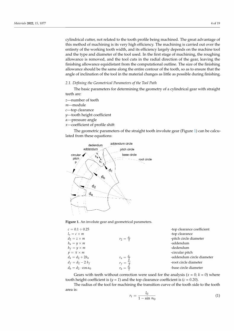
The geometric parameters of the straight tooth involute gear (Figure 1) can be calcu-lated from these equations:
Materials 2022, 15, x FOR PEER REVIEW 4 of 19
2. Materials and Methods
The paper presents a case of machining an involute profile of spur gears as a two-
parameter reeling of a tool along a given profile. The presented method is universal; any
profile obtained computationally can be machined. The tool used is a geometrically simple
cylindrical cutter, not related to the tooth profile being machined. The great advantage of
this method of machining is its very high efficiency. The machining is carried out over the
entirety of the working tooth width, and its efficiency largely depends on the machine
tool and the type and diameter of the tool used. In the first stage of machining, the rough-
ing allowance is removed, and the tool cuts in the radial direction of the gear, leaving the
finishing allowance equidistant from the computational outline. The size of the finishing
allowance should be the same along the entire contour of the tooth, so as to ensure that
the angle of inclination of the tool in the material changes as little as possible during fin-
ishing.
2.1. Defining the Geometrical Parameters of the Tool Path
The basic parameters for determining the geometry of a cylindrical gear with straight
teeth are:
z—number of teeth
m—module
c—top clearance
y—tooth height coefficient
α—pressure angle
x—coefficient of profile shift
The geometric parameters of the straight tooth involute gear (Figure 1) can be calcu-
lated from these equations:
Figure 1. An involute gear and geometrical parameters.
𝑐 = 0.1 ÷ 0.25 -top clearance coefficient
𝑙𝑜 = 𝑐 × 𝑚 -top clearance
𝑑2 = 𝑧 × 𝑚 𝑟2 =𝑑2
2
-pitch circle diameter
ℎ𝑎 = 𝑦 × 𝑚 -addendum
ℎ𝑓 = 𝑦 × 𝑚 -dedendum
𝑝 = 𝜋 × 𝑚 -circular pitch
𝑑𝑎 = 𝑑2 + 2ℎ𝑎 𝑟𝑎 =𝑑𝑎
2 -addendum circle diameter
Figure 1. An involute gear and geometrical parameters.
c = 0.1 ÷ 0.25 -top clearance coefficientlo = c × m -top clearanced2 = z × m r2 = d2
2 -pitch circle diameterha = y × m -addendumh f = y × m -dedendump = π × m -circular pitchda = d2 + 2ha ra = da
2 -addendum circle diameterd f = d2 − 2 h f r f =
d f2
-root circle diameterdb = d2 · cos α0 rb = db
2 -base circle diameter
Gears with teeth without correction were used for the analysis (x = 0; k = 0) wheretooth height coefficient is (y = 1) and the top clearance coefficient is (c = 0.20).
The radius of the tool for machining the transition curve of the tooth side to the tootharea is:
rt =l0
1 − sin ∝0(1)
Materials 2022, 15, 1077 5 of 19
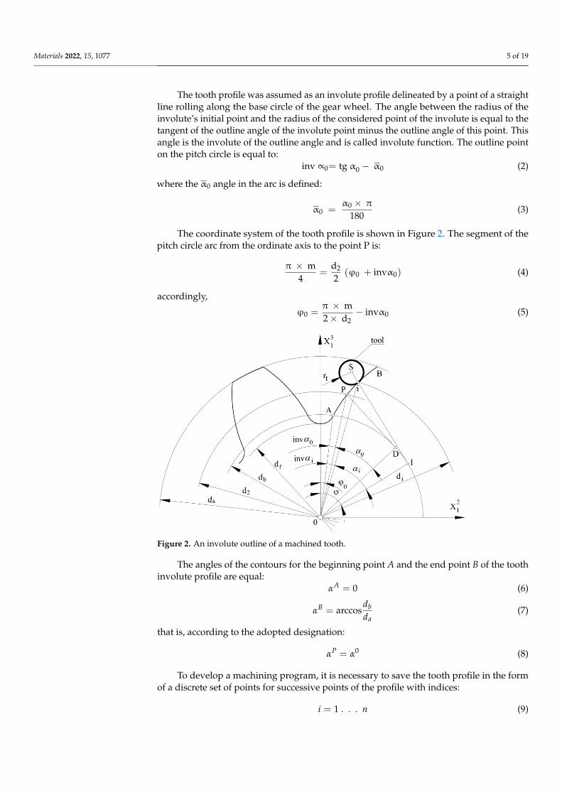
The tooth profile was assumed as an involute profile delineated by a point of a straightline rolling along the base circle of the gear wheel. The angle between the radius of theinvolute’s initial point and the radius of the considered point of the involute is equal to thetangent of the outline angle of the involute point minus the outline angle of this point. Thisangle is the involute of the outline angle and is called involute function. The outline pointon the pitch circle is equal to:
inv ∝0= tg α0 − α0 (2)
where the α0 angle in the arc is defined:
α0 =α0 × π
180(3)
The coordinate system of the tooth profile is shown in Figure 2. The segment of thepitch circle arc from the ordinate axis to the point P is:
π × m4
=d2
2(ϕ0 + invα0) (4)
accordingly,
ϕ0 =π × m2 × d2
− invα0 (5)
Materials 2022, 15, x FOR PEER REVIEW 6 of 19
αi = arccosdb
di (11)
The angle between the ordinate and the leading radius of the point of tangency nor-
mal to the outline at this point with the base circle is equal to:
φ = φ0 + αi = φ0 + tgαi (12)
Ultimately, the coordinates of any point of the tooth profile for the right side of the
tooth can be written in the coordinate systems as in Figure 2:
X12R =
db
2 (sinφ − φcosφ) (13)
X13R =
db
2(cosφ + φsinφ) (14)
Thus, the position of the cutter axis (tool setting) for shaping any point of the involute
tooth profile can be determined from the equation:
X12 Sr =
db
2sinφ − (
db
2φ + rt) cosφ (15)
X13 Sr =
db
2cosφ + (
db
2φ + rt) sinφ (16)
However, for the outline on the left side (right side of the tooth) it will be equal to:
x12(l)
= − x12(r)
(17)
x13(l)
= x13(r)
(18)
x12(Sl)
= − x12(Sr)
(19)
x13(Sl)
= − x13(Sr)
(20)
Figure 2. An involute outline of a machined tooth.
In the developed tooth profile processing technology, it is important to be able to
easily modify the tooth profile. Very often, the modification concerns only the contour
area that is not involved in the meshing, i.e., the root and the head of the tooth. The tran-
sition curve of the tooth profile side to the bottom land should be a tangent to the involute
Figure 2. An involute outline of a machined tooth.
The angles of the contours for the beginning point A and the end point B of the toothinvolute profile are equal:
αA = 0 (6)
αB = arccosdbda
(7)
that is, according to the adopted designation:
αP = α0 (8)
To develop a machining program, it is necessary to save the tooth profile in the formof a discrete set of points for successive points of the profile with indices:
i = 1 . . . n (9)
Materials 2022, 15, 1077 6 of 19
the radii of successive outline points can be determined from the equation:
di
2=
db2
+da − db2(n − 1)
(i − 1) (10)
On the other hand, the angles of the outline are analogous to the dependencies of(6) and (7)
αi = arccosdbdi
(11)
The angle between the ordinate and the leading radius of the point of tangency normalto the outline at this point with the base circle is equal to:
ϕ = ϕ0 + αi = ϕ0 + tgαi (12)
Ultimately, the coordinates of any point of the tooth profile for the right side of thetooth can be written in the coordinate systems as in Figure 2:
X2R1 =
db2
(sinϕ−ϕ cosϕ) (13)
X3R1 =
db2(cosϕ+ϕ sinϕ) (14)
Thus, the position of the cutter axis (tool setting) for shaping any point of the involutetooth profile can be determined from the equation:
X2 Sr1 =
db2
sinϕ−(
db2ϕ+ rt
)cosϕ (15)
X3 Sr1 =
db2
cosϕ+
(db2ϕ+ rt
)sinϕ (16)
However, for the outline on the left side (right side of the tooth) it will be equal to:
x2(l)1 = − x2(r)
1 (17)
x3(l)1 = x3(r)
1 (18)
x2(Sl)
1 = − x2(Sr)
1 (19)
x3(Sl)
1 = − x3(Sr)
1 (20)
In the developed tooth profile processing technology, it is important to be able to easilymodify the tooth profile. Very often, the modification concerns only the contour area that isnot involved in the meshing, i.e., the root and the head of the tooth. The transition curveof the tooth profile side to the bottom land should be a tangent to the involute profile atthe profile origin. Two machining cases can be defined to process a fragment of the toothprofile below the base circle. The first case concerns the machining that takes place inone cycle when cutting the main contour in the finishing cycle, assuming that it will be amilling cutter with a radius equal to the radius of the tooth bottom land rounding, or theradii of the rounding of the tooth sides at the transition to the bottom. In this case, the toolinclination angle in the material is larger, and it may cause a deterioration of the structureof the machined surface. In the second case, we can shape the transition contour with amilling cutter with a radius smaller than the radii of the rounding of the side contours at thebottom land. This method requires a machining strategy with one or two tools. The toolsmust maintain a smooth transition between the outline and the transition curve towards thetooth bottom. In the solution adopted for this research, one milling cutter with a diametersmaller than the width of the bottom of the tooth profiles was used, thanks to which, even
Materials 2022, 15, 1077 7 of 19
taking into account the allowances for finishing on both sides of the tooth, the tool couldwork in the areas of the inclination angle, ensuring stable operation without vibrations.The adopted machining strategy was also determined by a higher efficiency (machiningthe entire gear with one tool) and the possibility of performing a qualitative assessmentof machining. The method assumes that in the process of machining the transition curve,as well as in the entire process of machining the tooth profile, the gear wheel performs arelative rotational movement C around the Z axis, while the shaped bottom land takes asymmetrical position with respect to the adopted coordinate system for the needs of theprofile calculations.
Tooth Profile Modification
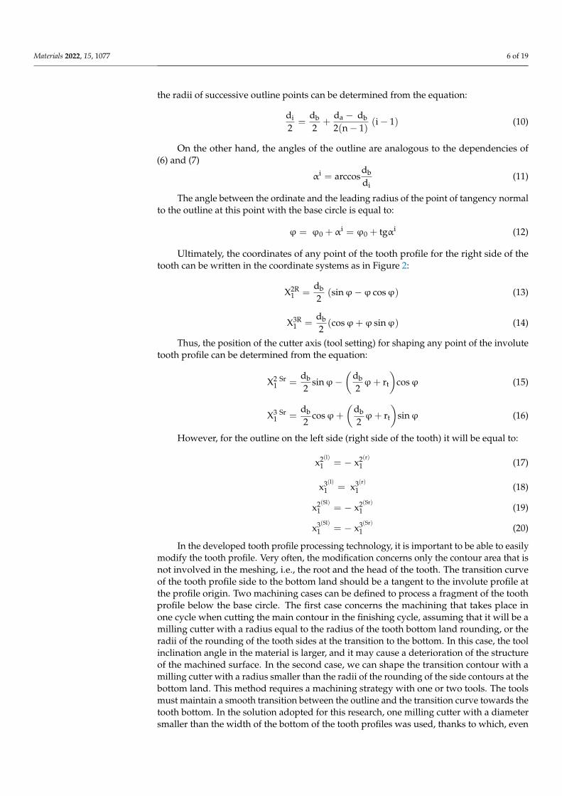
In the tested method, we can very easily apply a modification of the outline, whichmay consist of replacing the tooth forming profile at the considered point of the outlinewith an arc of a circle or a straight line. Such a solution can be used to improve the qualityof gear operation, and it can be used for gears with a limited number of teeth in order toavoid the interference phenomenon. Figure 3a shows an analytically obtained involutetooth profile—without modification of the root and tooth head; such a case was processedon the machine and further analysed. Figure 3b,c show the modified contours; they can bemachined according to the same machining strategy, as the size of the modification doesnot affect the nature of the process and is only determined by the diameter of the millingcutter used.
Materials 2022, 15, x FOR PEER REVIEW 7 of 19
profile at the profile origin. Two machining cases can be defined to process a fragment of
the tooth profile below the base circle. The first case concerns the machining that takes
place in one cycle when cutting the main contour in the finishing cycle, assuming that it
will be a milling cutter with a radius equal to the radius of the tooth bottom land rounding,
or the radii of the rounding of the tooth sides at the transition to the bottom. In this case,
the tool inclination angle in the material is larger, and it may cause a deterioration of the
structure of the machined surface. In the second case, we can shape the transition contour
with a milling cutter with a radius smaller than the radii of the rounding of the side con-
tours at the bottom land. This method requires a machining strategy with one or two tools.
The tools must maintain a smooth transition between the outline and the transition curve
towards the tooth bottom. In the solution adopted for this research, one milling cutter
with a diameter smaller than the width of the bottom of the tooth profiles was used, thanks
to which, even taking into account the allowances for finishing on both sides of the tooth,
the tool could work in the areas of the inclination angle, ensuring stable operation without
vibrations. The adopted machining strategy was also determined by a higher efficiency
(machining the entire gear with one tool) and the possibility of performing a qualitative
assessment of machining. The method assumes that in the process of machining the tran-
sition curve, as well as in the entire process of machining the tooth profile, the gear wheel
performs a relative rotational movement C around the Z axis, while the shaped bottom
land takes a symmetrical position with respect to the adopted coordinate system for the
needs of the profile calculations.
Tooth Profile Modification
In the tested method, we can very easily apply a modification of the outline, which
may consist of replacing the tooth forming profile at the considered point of the outline
with an arc of a circle or a straight line. Such a solution can be used to improve the quality
of gear operation, and it can be used for gears with a limited number of teeth in order to
avoid the interference phenomenon. Figure 3a shows an analytically obtained involute
tooth profile—without modification of the root and tooth head; such a case was processed
on the machine and further analysed. Figure 3b,c show the modified contours; they can
be machined according to the same machining strategy, as the size of the modification
does not affect the nature of the process and is only determined by the diameter of the
milling cutter used.
(a) (b) (c)
Figure 3. Tooth profiles. (a) involute without modification, (b) involute with modification along an
arc of the head of the tooth, (c) involute with modification along a straight line of the head of the
tooth.
Figure 3. Tooth profiles. (a) involute without modification, (b) involute with modification alongan arc of the head of the tooth, (c) involute with modification along a straight line of the head ofthe tooth.
The tool used is a cylindrical cutter that is not geometrically related to the machinedtooth profile (the tool and the machined gear are not mutually enveloped). It is a classiccase of a two-parameter circumference (the form of the machined surface does not dependon the tool geometry). The developed calculation algorithm is universal and can be usedto prepare the technology for the machining of any tooth, both external and internal, on anumerically controlled lathe with the use of driven tools.
2.2. Machining Process
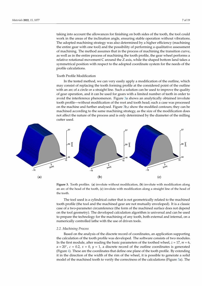
Based on the analysis of the discrete record of coordinates, an application supportingthe calculation of the tooth profile was developed. The software consists of two modules.In the first module, after reading the basic parameters of the toothed wheel, z = 17, m = 6,α = 20◦, c = 0.2, x = 0, y = 1, a discrete record of the outline coordinates is generated(Figure 4). These are the coordinates that define one plane of the tooth profile. By extendingit in the direction of the width of the rim of the wheel, it is possible to generate a solidmodel of the machined tooth to verify the correctness of the calculations (Figure 3a). The
Materials 2022, 15, 1077 8 of 19
tool path can be saved in a separate text file, in which the tool diameter has been takeninto account.
Materials 2022, 15, x FOR PEER REVIEW 8 of 19
The tool used is a cylindrical cutter that is not geometrically related to the machined
tooth profile (the tool and the machined gear are not mutually enveloped). It is a classic
case of a two-parameter circumference (the form of the machined surface does not depend
on the tool geometry). The developed calculation algorithm is universal and can be used
to prepare the technology for the machining of any tooth, both external and internal, on a
numerically controlled lathe with the use of driven tools.
2.2. Machining Process
Based on the analysis of the discrete record of coordinates, an application supporting
the calculation of the tooth profile was developed. The software consists of two modules.
In the first module, after reading the basic parameters of the toothed wheel, z = 17, m = 6,
α = 20°, c = 0.2, x = 0, y = 1, a discrete record of the outline coordinates is generated (Figure
4). These are the coordinates that define one plane of the tooth profile. By extending it in
the direction of the width of the rim of the wheel, it is possible to generate a solid model
of the machined tooth to verify the correctness of the calculations (Figure 3a). The tool
path can be saved in a separate text file, in which the tool diameter has been taken into
account.
Figure 4. A tooth outline and tool path generating software.
The obtained tool path coordinates take into account the resolution of the tooth pro-
file calculations, which should be adjusted depending on the size and module of the ma-
chined gear. The entire generated program includes machine control functions in accord-
ance with the ISO code. It is so universal that it can be adapted to any machine tool that
can be programmed according to standardized functions. The generated toolpath is saved
in a text file and can be merged with the main program code of the indicated control sys-
tem. When adapting the tool path obtained from the calculations, it is necessary that the
contours generated in the program can be recreated without the program declaration of
tool radius compensation. The tool radius compensation is included in the tool path cal-
culation step. Figure 5 shows the machining program integrated for the Sinumerik 840 Dsl
control system.
Program blocks 20–100 include machining for blank parts of the gear, including the
centering bore, while lines 140–2900 contain the program code for machining one space
between the sides of the teeth—the left side of the tooth profile (right) and the right side
of the tooth profile (left). Block 2890 includes a split command for machining the next gear
segment. Subsequently, the program between markers MARK1 and MARK2 is repeated
Figure 4. A tooth outline and tool path generating software.
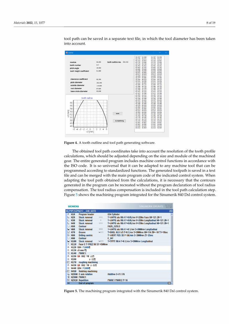
The obtained tool path coordinates take into account the resolution of the tooth profilecalculations, which should be adjusted depending on the size and module of the machinedgear. The entire generated program includes machine control functions in accordance withthe ISO code. It is so universal that it can be adapted to any machine tool that can beprogrammed according to standardized functions. The generated toolpath is saved in a textfile and can be merged with the main program code of the indicated control system. Whenadapting the tool path obtained from the calculations, it is necessary that the contoursgenerated in the program can be recreated without the program declaration of tool radiuscompensation. The tool radius compensation is included in the tool path calculation step.Figure 5 shows the machining program integrated for the Sinumerik 840 Dsl control system.
Materials 2022, 15, x FOR PEER REVIEW 9 of 19
16 times. The gear with an involute profile with the geometrical parameters indicated in
Table 1 was machined. The width of the gear rim of has been limited to 10 mm so that the
tool is not significantly loaded during the machining process.
Figure 5. The machining program integrated with the Sinumerik 840 Dsl control system.
Table 1. The machined gear parameters.
Module
[mm]
Number of
Teeth
Pitch Angle
[deg]
Tooth Height
Coefficient
Clearance Coeffi-
cient
[mm]
Face Width
[mm]
6 17 20 1.0 0.20 10
A numerically controlled lathe from DMG MORI, model CLX350V4, equipped with
a Sinumerik 840D sl control system, was used for machining. The machine is also
equipped with the ShopTurn programming overlay, allowing for conversational dialogue
programming. The blank was made of a uniform AlSi1MgMn aluminium material,
mounted in the three-jaw self-centering chuck of the lathe (Figure 6a). The Mahr MarCator
1075R (Mahr GmbH, Göttingen, Germany) measuring sensor with a measuring resolution
of 5μ and a reading resolution of 1μ was used to check the correct mounting—parallelism
of the face of the gear in relation to the lathe spindle. By adjusting the clamping force of
the jaws, it was possible to obtain a parallelism deviation in the X axis of 6μ. For machin-
ing, a cylindrical cutter—ϕ6 mm, VHM, with high accuracy, with polished chip flutes for
better chip evacuation—was used (Figure 6b,c). A cylindrical milling cutter with 5 blades,
a blade diameter tolerance not exceeding 4μm and the maximum allowable milling width
of 0.2 mm for a Ø 6 tool was used. During machining, the chips were discharged with
compressed air. The maximum rotation speed of the tool is 8000 rpm and the feed rate is
0.385 mm/rev. A tool shank according to DIN 6535 HA in h6 tolerance was used. A driven
tool holder with a straight geometry (parallel to the spindle) was used, SAUTER VDI30
(Figure 6), with a mounting type ER25 and maintained a rotational accuracy of ≤2 µm.
Figure 5. The machining program integrated with the Sinumerik 840 Dsl control system.
Materials 2022, 15, 1077 9 of 19
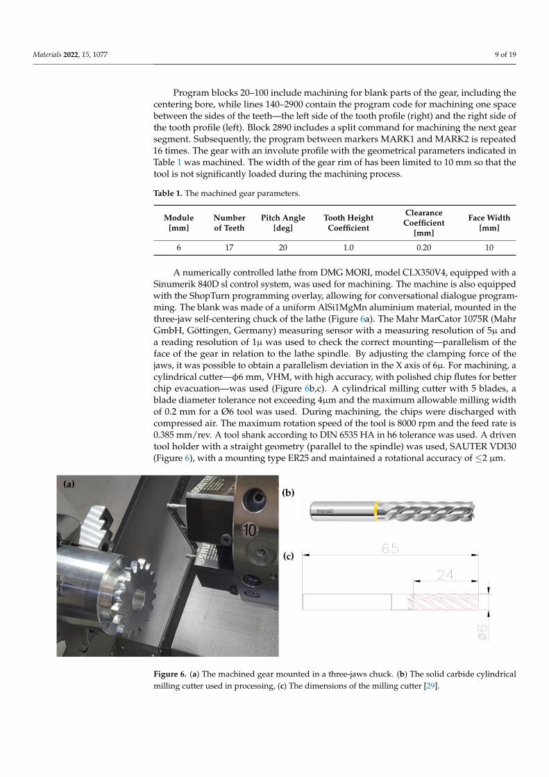
Program blocks 20–100 include machining for blank parts of the gear, including thecentering bore, while lines 140–2900 contain the program code for machining one spacebetween the sides of the teeth—the left side of the tooth profile (right) and the right side ofthe tooth profile (left). Block 2890 includes a split command for machining the next gearsegment. Subsequently, the program between markers MARK1 and MARK2 is repeated16 times. The gear with an involute profile with the geometrical parameters indicated inTable 1 was machined. The width of the gear rim of has been limited to 10 mm so that thetool is not significantly loaded during the machining process.
Table 1. The machined gear parameters.
Module[mm]
Numberof Teeth
Pitch Angle[deg]
Tooth HeightCoefficient
ClearanceCoefficient
[mm]
Face Width[mm]
6 17 20 1.0 0.20 10
A numerically controlled lathe from DMG MORI, model CLX350V4, equipped with aSinumerik 840D sl control system, was used for machining. The machine is also equippedwith the ShopTurn programming overlay, allowing for conversational dialogue program-ming. The blank was made of a uniform AlSi1MgMn aluminium material, mounted in thethree-jaw self-centering chuck of the lathe (Figure 6a). The Mahr MarCator 1075R (MahrGmbH, Göttingen, Germany) measuring sensor with a measuring resolution of 5µ anda reading resolution of 1µ was used to check the correct mounting—parallelism of theface of the gear in relation to the lathe spindle. By adjusting the clamping force of thejaws, it was possible to obtain a parallelism deviation in the X axis of 6µ. For machining, acylindrical cutter—φ6 mm, VHM, with high accuracy, with polished chip flutes for betterchip evacuation—was used (Figure 6b,c). A cylindrical milling cutter with 5 blades, ablade diameter tolerance not exceeding 4µm and the maximum allowable milling widthof 0.2 mm for a Ø6 tool was used. During machining, the chips were discharged withcompressed air. The maximum rotation speed of the tool is 8000 rpm and the feed rate is0.385 mm/rev. A tool shank according to DIN 6535 HA in h6 tolerance was used. A driventool holder with a straight geometry (parallel to the spindle) was used, SAUTER VDI30(Figure 6), with a mounting type ER25 and maintained a rotational accuracy of ≤2 µm.
Materials 2022, 15, x FOR PEER REVIEW 10 of 19
Figure 6. (a) The machined gear mounted in a three-jaws chuck. (b) The solid carbide cylindrical
milling cutter used in processing, (c) The dimensions of the milling cutter [29].
The developed machining program included roughing—a plunge division of the
space between left and right tooth profile at the level of 10 layers (Figure 7a)—after which
an equidistant allowance for finishing of 0.15 mm was left on the profiles. The allowance
was removed in one finishing pass of the tool according to the calculated trajectory move-
ment (Figure 7b).
Figure 7. The adopted machining strategy. (a) the roughing and finishing tool path, (b) the ma-
chining strategy.
The involute line was built of straight sections, and its resolution depends mainly on
the processing capabilities of the machine control system itself. In the examined case, the
calculations assumed the resolution of the involute outline in the form of 500 straight line
segments for one side of the tooth profile. Therefore, it is not difficult to calculate that the
complete machining of one space between tooth profiles for the tested method is about
1050 program lines. During the test work of the machining, an important thing was no-
ticed that influenced the efficiency of the program implementation. To ensure efficient
operation of the machine control system, the main machining program should cooperate
with roughing and finishing subroutines that were sequentially loaded into the main pro-
gram and executed. This solution significantly shortened the time of the graphical presen-
tation of the program on the machine’s desktop. One tool was used for roughing and fin-
ishing in the entire process. This assumption was to allow the assessment of the effect of
its wear on the condition of the machined surfaces and the accuracy of the entire gear.
Figure 6. (a) The machined gear mounted in a three-jaws chuck. (b) The solid carbide cylindricalmilling cutter used in processing, (c) The dimensions of the milling cutter [29].
Materials 2022, 15, 1077 10 of 19
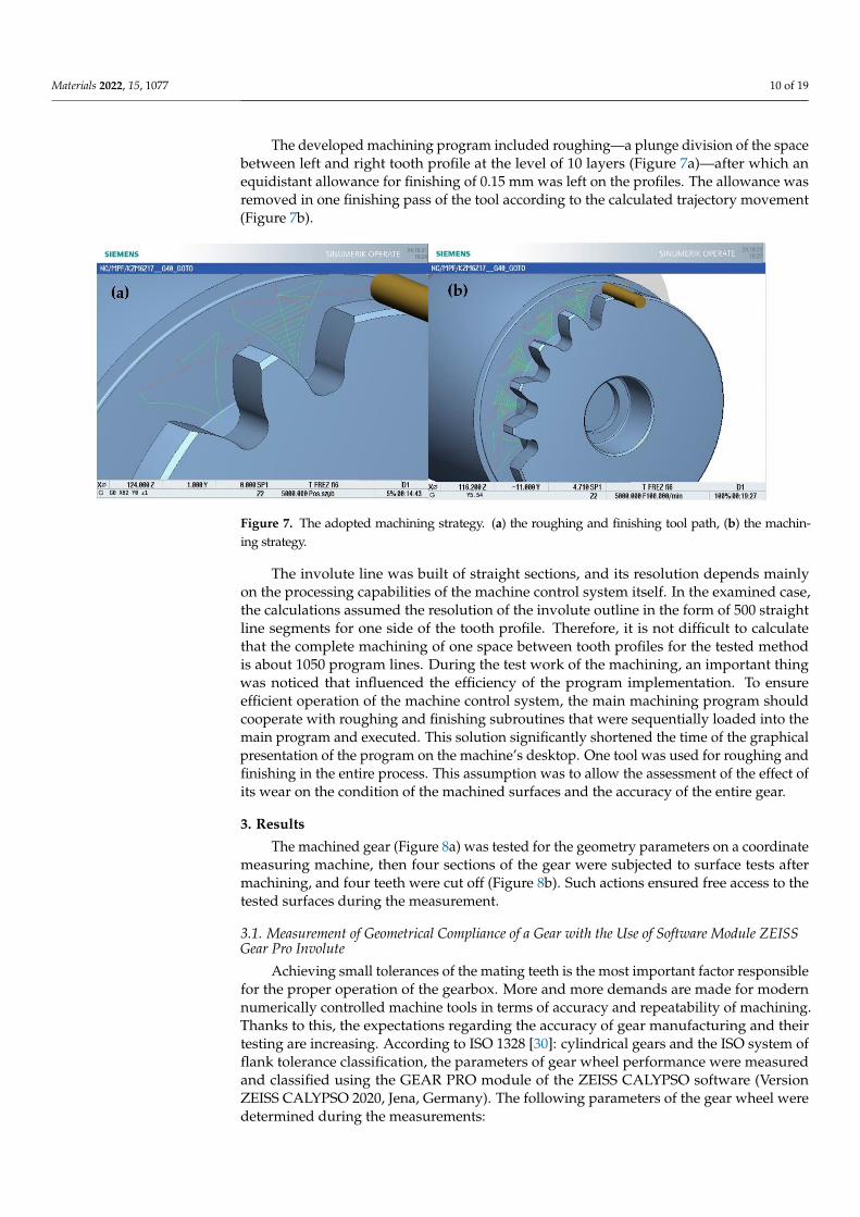
The developed machining program included roughing—a plunge division of the spacebetween left and right tooth profile at the level of 10 layers (Figure 7a)—after which anequidistant allowance for finishing of 0.15 mm was left on the profiles. The allowance wasremoved in one finishing pass of the tool according to the calculated trajectory movement(Figure 7b).
Materials 2022, 15, x FOR PEER REVIEW 10 of 19
Figure 6. (a) The machined gear mounted in a three-jaws chuck. (b) The solid carbide cylindrical
milling cutter used in processing, (c) The dimensions of the milling cutter [29].
The developed machining program included roughing—a plunge division of the
space between left and right tooth profile at the level of 10 layers (Figure 7a)—after which
an equidistant allowance for finishing of 0.15 mm was left on the profiles. The allowance
was removed in one finishing pass of the tool according to the calculated trajectory move-
ment (Figure 7b).
Figure 7. The adopted machining strategy. (a) the roughing and finishing tool path, (b) the ma-
chining strategy.
The involute line was built of straight sections, and its resolution depends mainly on
the processing capabilities of the machine control system itself. In the examined case, the
calculations assumed the resolution of the involute outline in the form of 500 straight line
segments for one side of the tooth profile. Therefore, it is not difficult to calculate that the
complete machining of one space between tooth profiles for the tested method is about
1050 program lines. During the test work of the machining, an important thing was no-
ticed that influenced the efficiency of the program implementation. To ensure efficient
operation of the machine control system, the main machining program should cooperate
with roughing and finishing subroutines that were sequentially loaded into the main pro-
gram and executed. This solution significantly shortened the time of the graphical presen-
tation of the program on the machine’s desktop. One tool was used for roughing and fin-
ishing in the entire process. This assumption was to allow the assessment of the effect of
its wear on the condition of the machined surfaces and the accuracy of the entire gear.
Figure 7. The adopted machining strategy. (a) the roughing and finishing tool path, (b) the machin-ing strategy.
The involute line was built of straight sections, and its resolution depends mainlyon the processing capabilities of the machine control system itself. In the examined case,the calculations assumed the resolution of the involute outline in the form of 500 straightline segments for one side of the tooth profile. Therefore, it is not difficult to calculatethat the complete machining of one space between tooth profiles for the tested methodis about 1050 program lines. During the test work of the machining, an important thingwas noticed that influenced the efficiency of the program implementation. To ensureefficient operation of the machine control system, the main machining program shouldcooperate with roughing and finishing subroutines that were sequentially loaded into themain program and executed. This solution significantly shortened the time of the graphicalpresentation of the program on the machine’s desktop. One tool was used for roughing andfinishing in the entire process. This assumption was to allow the assessment of the effect ofits wear on the condition of the machined surfaces and the accuracy of the entire gear.
3. Results
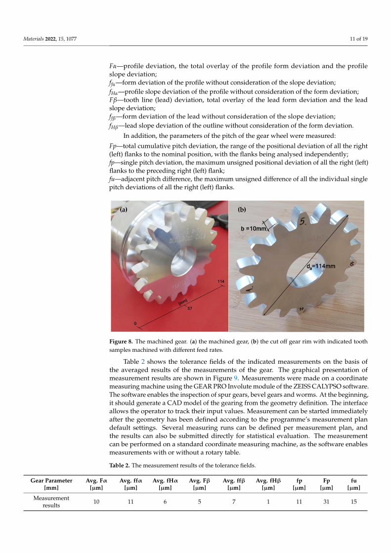
The machined gear (Figure 8a) was tested for the geometry parameters on a coordinatemeasuring machine, then four sections of the gear were subjected to surface tests aftermachining, and four teeth were cut off (Figure 8b). Such actions ensured free access to thetested surfaces during the measurement.
3.1. Measurement of Geometrical Compliance of a Gear with the Use of Software Module ZEISSGear Pro Involute
Achieving small tolerances of the mating teeth is the most important factor responsiblefor the proper operation of the gearbox. More and more demands are made for modernnumerically controlled machine tools in terms of accuracy and repeatability of machining.Thanks to this, the expectations regarding the accuracy of gear manufacturing and theirtesting are increasing. According to ISO 1328 [30]: cylindrical gears and the ISO system offlank tolerance classification, the parameters of gear wheel performance were measuredand classified using the GEAR PRO module of the ZEISS CALYPSO software (VersionZEISS CALYPSO 2020, Jena, Germany). The following parameters of the gear wheel weredetermined during the measurements:
Materials 2022, 15, 1077 11 of 19
Fα—profile deviation, the total overlay of the profile form deviation and the profileslope deviation;ffα—form deviation of the profile without consideration of the slope deviation;fHα—profile slope deviation of the profile without consideration of the form deviation;Fβ—tooth line (lead) deviation, total overlay of the lead form deviation and the leadslope deviation;ffβ—form deviation of the lead without consideration of the slope deviation;fHβ—lead slope deviation of the outline without consideration of the form deviation.
In addition, the parameters of the pitch of the gear wheel were measured:
Fp—total cumulative pitch deviation, the range of the positional deviation of all the right(left) flanks to the nominal position, with the flanks being analysed independently;fp—single pitch deviation, the maximum unsigned positional deviation of all the right (left)flanks to the preceding right (left) flank;fu—adjacent pitch difference, the maximum unsigned difference of all the individual singlepitch deviations of all the right (left) flanks.
Materials 2022, 15, x FOR PEER REVIEW 11 of 19
3. Results
The machined gear (Figure 8a) was tested for the geometry parameters on a coordi-
nate measuring machine, then four sections of the gear were subjected to surface tests after
machining, and four teeth were cut off (Figure 8b). Such actions ensured free access to the
tested surfaces during the measurement.
Figure 8. The machined gear. (a) the machined gear, (b) the cut off gear rim with indicated tooth
samples machined with different feed rates.
3.1. Measurement of Geometrical Compliance of a Gear With the Use of Software Module ZEISS
Gear Pro Involute
Achieving small tolerances of the mating teeth is the most important factor responsi-
ble for the proper operation of the gearbox. More and more demands are made for modern
numerically controlled machine tools in terms of accuracy and repeatability of machining.
Thanks to this, the expectations regarding the accuracy of gear manufacturing and their
testing are increasing. According to ISO 1328 [30]: cylindrical gears and the ISO system of
flank tolerance classification, the parameters of gear wheel performance were measured
and classified using the GEAR PRO module of the ZEISS CALYPSO software (Version
ZEISS CALYPSO 2020, Jena, Germany). The following parameters of the gear wheel were
determined during the measurements:
Fα—profile deviation, the total overlay of the profile form deviation and the profile slope
deviation;
ffα—form deviation of the profile without consideration of the slope deviation;
fHα—profile slope deviation of the profile without consideration of the form deviation;
Fβ—tooth line (lead) deviation, total overlay of the lead form deviation and the lead slope
deviation;
ffβ—form deviation of the lead without consideration of the slope deviation;
fHβ—lead slope deviation of the outline without consideration of the form deviation.
In addition, the parameters of the pitch of the gear wheel were measured:
Fp—total cumulative pitch deviation, the range of the positional deviation of all the right
(left) flanks to the nominal position, with the flanks being analysed independently;
fp—single pitch deviation, the maximum unsigned positional deviation of all the right
(left) flanks to the preceding right (left) flank;
fu—adjacent pitch difference, the maximum unsigned difference of all the individual sin-
gle pitch deviations of all the right (left) flanks.
Figure 8. The machined gear. (a) the machined gear, (b) the cut off gear rim with indicated toothsamples machined with different feed rates.
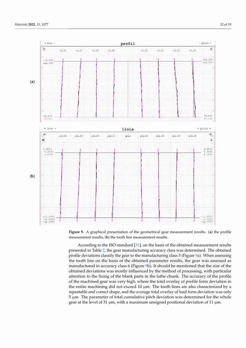
Table 2 shows the tolerance fields of the indicated measurements on the basis ofthe averaged results of the measurements of the gear. The graphical presentation ofmeasurement results are shown in Figure 9. Measurements were made on a coordinatemeasuring machine using the GEAR PRO Involute module of the ZEISS CALYPSO software.The software enables the inspection of spur gears, bevel gears and worms. At the beginning,it should generate a CAD model of the gearing from the geometry definition. The interfaceallows the operator to track their input values. Measurement can be started immediatelyafter the geometry has been defined according to the programme’s measurement plandefault settings. Several measuring runs can be defined per measurement plan, andthe results can also be submitted directly for statistical evaluation. The measurementcan be performed on a standard coordinate measuring machine, as the software enablesmeasurements with or without a rotary table.
Table 2. The measurement results of the tolerance fields.
Gear Parameter[mm]
Avg. Fα[µm]
Avg. ffα[µm]
Avg. fHα
[µm]Avg. Fβ
[µm]Avg. ffβ
[µm]Avg. fHβ
[µm]fp
[µm]Fp
[µm]fu
[µm]
Measurementresults 10 11 6 5 7 1 11 31 15
Materials 2022, 15, 1077 12 of 19
Materials 2022, 15, x FOR PEER REVIEW 12 of 19
Table 2 shows the tolerance fields of the indicated measurements on the basis of the
averaged results of the measurements of the gear. The graphical presentation of measure-
ment results are shown in Figure 9. Measurements were made on a coordinate measuring
machine using the GEAR PRO Involute module of the ZEISS CALYPSO software. The
software enables the inspection of spur gears, bevel gears and worms. At the beginning,
it should generate a CAD model of the gearing from the geometry definition. The interface
allows the operator to track their input values. Measurement can be started immediately
after the geometry has been defined according to the programme’s measurement plan
default settings. Several measuring runs can be defined per measurement plan, and the
results can also be submitted directly for statistical evaluation. The measurement can be
performed on a standard coordinate measuring machine, as the software enables meas-
urements with or without a rotary table.
Table 2. The measurement results of the tolerance fields.
Gear Parameter
[mm]
Avg. Fα
[μm]
Avg. ffα
[μm]
Avg. fHα
[μm]
Avg. Fβ
[μm]
Avg. ffβ
[μm]
Avg. fHβ
[μm]
fp
[μm]
Fp
[μm]
fu
[μm]
Measurement results 10 11 6 5 7 1 11 31 15
According to the ISO standard [31], on the basis of the obtained measurement results
presented in Table 2, the gear manufacturing accuracy class was determined. The obtained
profile deviations classify the gear to the manufacturing class 5 (Figure 9a). When as-
sessing the tooth line on the basis of the obtained parameter results, the gear was assessed
as manufactured in accuracy class 6 (Figure 9b). It should be mentioned that the size of
the obtained deviations was mostly influenced by the method of processing, with partic-
ular attention to the fixing of the blank parts in the lathe chunk. The accuracy of the profile
of the machined gear was very high, where the total overlay of profile form deviation in
the entire machining did not exceed 10 μm. The tooth lines are also characterized by a
repeatable and correct shape, and the average total overlay of lead form deviation was
only 5 μm. The parameter of total cumulative pitch deviation was determined for the
whole gear at the level of 31 μm, with a maximum unsigned positional deviation of 11
μm.
(a)
Materials 2022, 15, x FOR PEER REVIEW 13 of 19
(b)
Figure 9. A graphical presentation of the geometrical gear measurement results. (a) the profile meas-
urement results, (b) the tooth line measurement results.
3.2. Measurement of the Structure of the Tooth Surfaces
In the next stage of the analysis, the gear was assessed on a Taylor Hobson Talysurf
120 (Taylor Hobson, New Star Road, Leicester, UK, 2012) laboratory contact profile
graphometer. A measuring blade with a 2 µm tip was used for the measurement. The
roughness of the machined tooth profiles was measured in the direction of the profile in
the half of the gear rim width in four sections, machined in various ranges of feed speeds
(Figure 10). Ra is the arithmetic mean roughness value from the amounts of all profile
values. Ra does not differentiate between peaks and valleys, and therefore has a relatively
weak information character, while Rz presents the maximum height of profile as the av-
erage value of the five Rz values. The Ra parameter reacts poorly and has local changes in
the surface structure, so its value often does not give a clear picture of the surface condi-
tion. For this reason, the roughness parameter Rz was additionally selected to describe
the surface condition. The machining times were simulated depending on the feed speed
of the tool. In principle, roughing machining was carried out with the same feed value of
1800 mm/min. This is the nominal value for the tool used, taking into account the rota-
tional speed of 4500 rev/min, the maximum for the driven holder used. It should be noted
that the length of the tool path in finishing in relation to roughing is 40/60.
Figure 9. A graphical presentation of the geometrical gear measurement results. (a) the profilemeasurement results, (b) the tooth line measurement results.
According to the ISO standard [31], on the basis of the obtained measurement resultspresented in Table 2, the gear manufacturing accuracy class was determined. The obtainedprofile deviations classify the gear to the manufacturing class 5 (Figure 9a). When assessingthe tooth line on the basis of the obtained parameter results, the gear was assessed asmanufactured in accuracy class 6 (Figure 9b). It should be mentioned that the size of theobtained deviations was mostly influenced by the method of processing, with particularattention to the fixing of the blank parts in the lathe chunk. The accuracy of the profileof the machined gear was very high, where the total overlay of profile form deviation inthe entire machining did not exceed 10 µm. The tooth lines are also characterized by arepeatable and correct shape, and the average total overlay of lead form deviation was only5 µm. The parameter of total cumulative pitch deviation was determined for the wholegear at the level of 31 µm, with a maximum unsigned positional deviation of 11 µm.
Materials 2022, 15, 1077 13 of 19
3.2. Measurement of the Structure of the Tooth Surfaces
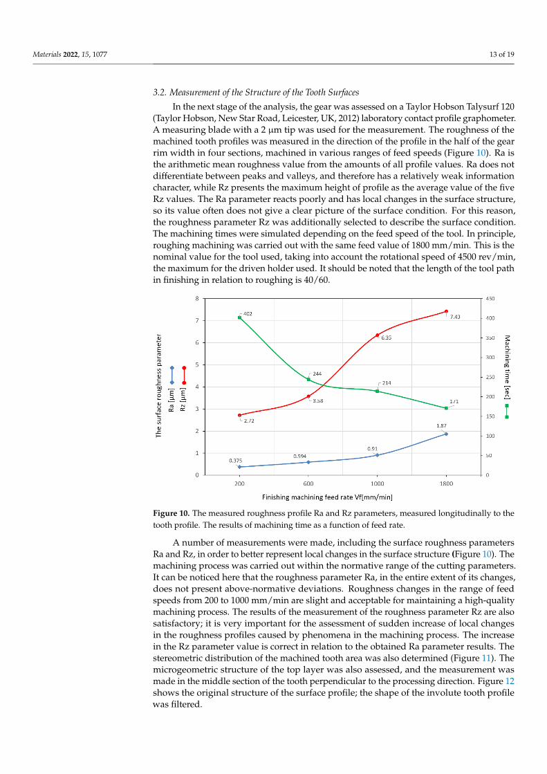
In the next stage of the analysis, the gear was assessed on a Taylor Hobson Talysurf 120(Taylor Hobson, New Star Road, Leicester, UK, 2012) laboratory contact profile graphometer.A measuring blade with a 2 µm tip was used for the measurement. The roughness of themachined tooth profiles was measured in the direction of the profile in the half of the gearrim width in four sections, machined in various ranges of feed speeds (Figure 10). Ra isthe arithmetic mean roughness value from the amounts of all profile values. Ra does notdifferentiate between peaks and valleys, and therefore has a relatively weak informationcharacter, while Rz presents the maximum height of profile as the average value of the fiveRz values. The Ra parameter reacts poorly and has local changes in the surface structure,so its value often does not give a clear picture of the surface condition. For this reason,the roughness parameter Rz was additionally selected to describe the surface condition.The machining times were simulated depending on the feed speed of the tool. In principle,roughing machining was carried out with the same feed value of 1800 mm/min. This is thenominal value for the tool used, taking into account the rotational speed of 4500 rev/min,the maximum for the driven holder used. It should be noted that the length of the tool pathin finishing in relation to roughing is 40/60.
Materials 2022, 15, x FOR PEER REVIEW 14 of 19
Figure 10. The measured roughness profile Ra and Rz parameters, measured longitudinally to the
tooth profile. The results of machining time as a function of feed rate.
A number of measurements were made, including the surface roughness parameters
Ra and Rz, in order to better represent local changes in the surface structure (Figure 10).
The machining process was carried out within the normative range of the cutting param-
eters. It can be noticed here that the roughness parameter Ra, in the entire extent of its
changes, does not present above-normative deviations. Roughness changes in the range
of feed speeds from 200 to 1000 mm/min are slight and acceptable for maintaining a high-
quality machining process. The results of the measurement of the roughness parameter
Rz are also satisfactory; it is very important for the assessment of sudden increase of local
changes in the roughness profiles caused by phenomena in the machining process. The
increase in the Rz parameter value is correct in relation to the obtained Ra parameter re-
sults. The stereometric distribution of the machined tooth area was also determined (Fig-
ure 11). The microgeometric structure of the top layer was also assessed, and the meas-
urement was made in the middle section of the tooth perpendicular to the processing di-
rection. Figure 12 shows the original structure of the surface profile; the shape of the in-
volute tooth profile was filtered.
Figure 11. A stereometric distribution of the machined tooth—sample 4, machined with a feed speed
of Vf = 1800 mm/min.
Figure 10. The measured roughness profile Ra and Rz parameters, measured longitudinally to thetooth profile. The results of machining time as a function of feed rate.
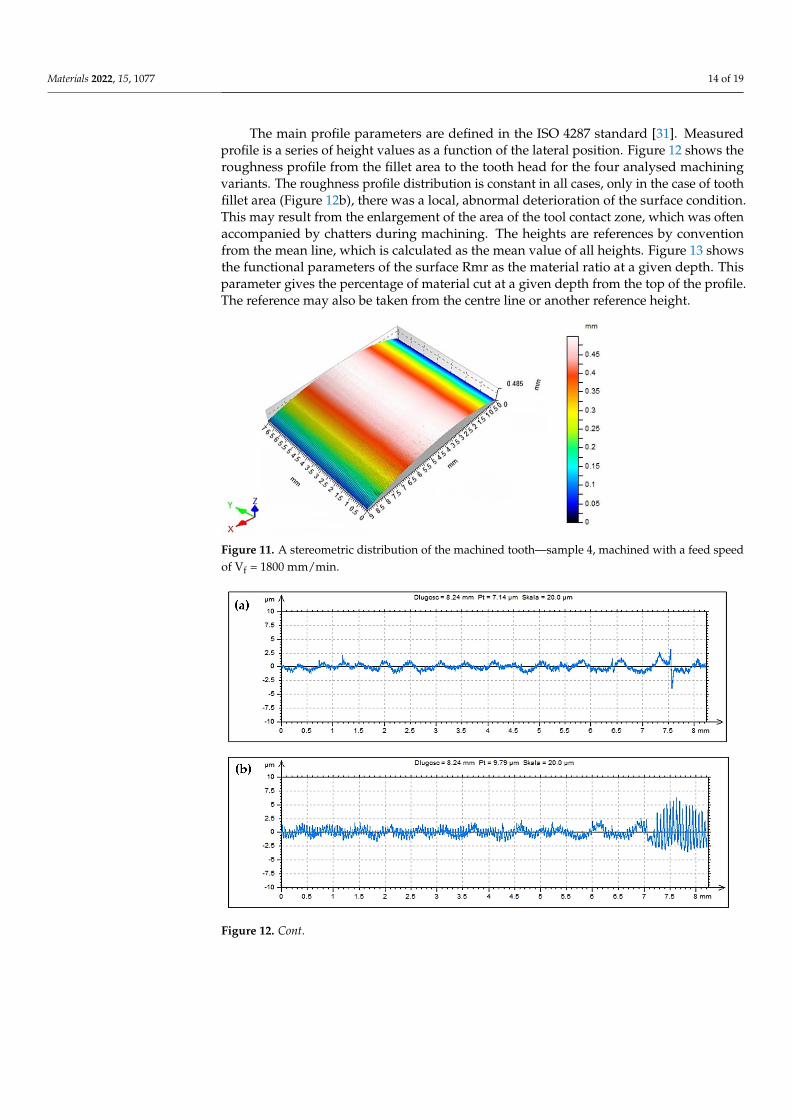
A number of measurements were made, including the surface roughness parametersRa and Rz, in order to better represent local changes in the surface structure (Figure 10). Themachining process was carried out within the normative range of the cutting parameters.It can be noticed here that the roughness parameter Ra, in the entire extent of its changes,does not present above-normative deviations. Roughness changes in the range of feedspeeds from 200 to 1000 mm/min are slight and acceptable for maintaining a high-qualitymachining process. The results of the measurement of the roughness parameter Rz are alsosatisfactory; it is very important for the assessment of sudden increase of local changesin the roughness profiles caused by phenomena in the machining process. The increasein the Rz parameter value is correct in relation to the obtained Ra parameter results. Thestereometric distribution of the machined tooth area was also determined (Figure 11). Themicrogeometric structure of the top layer was also assessed, and the measurement wasmade in the middle section of the tooth perpendicular to the processing direction. Figure 12shows the original structure of the surface profile; the shape of the involute tooth profilewas filtered.
Materials 2022, 15, 1077 14 of 19
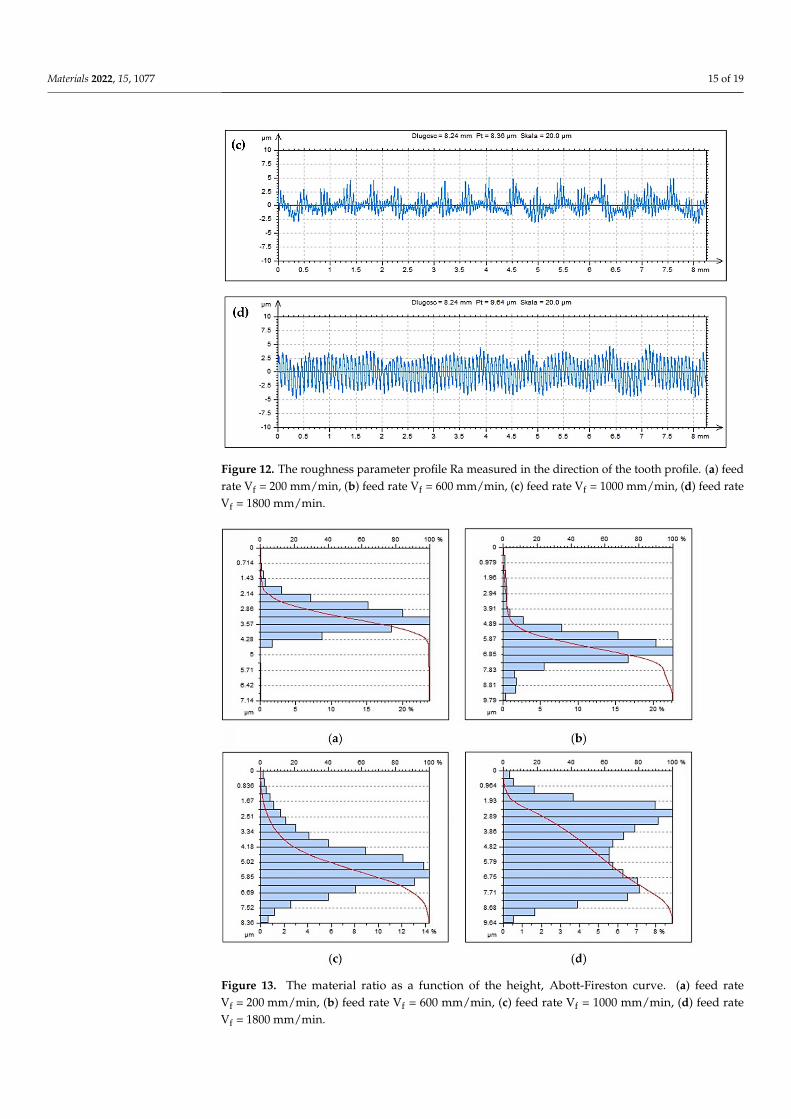
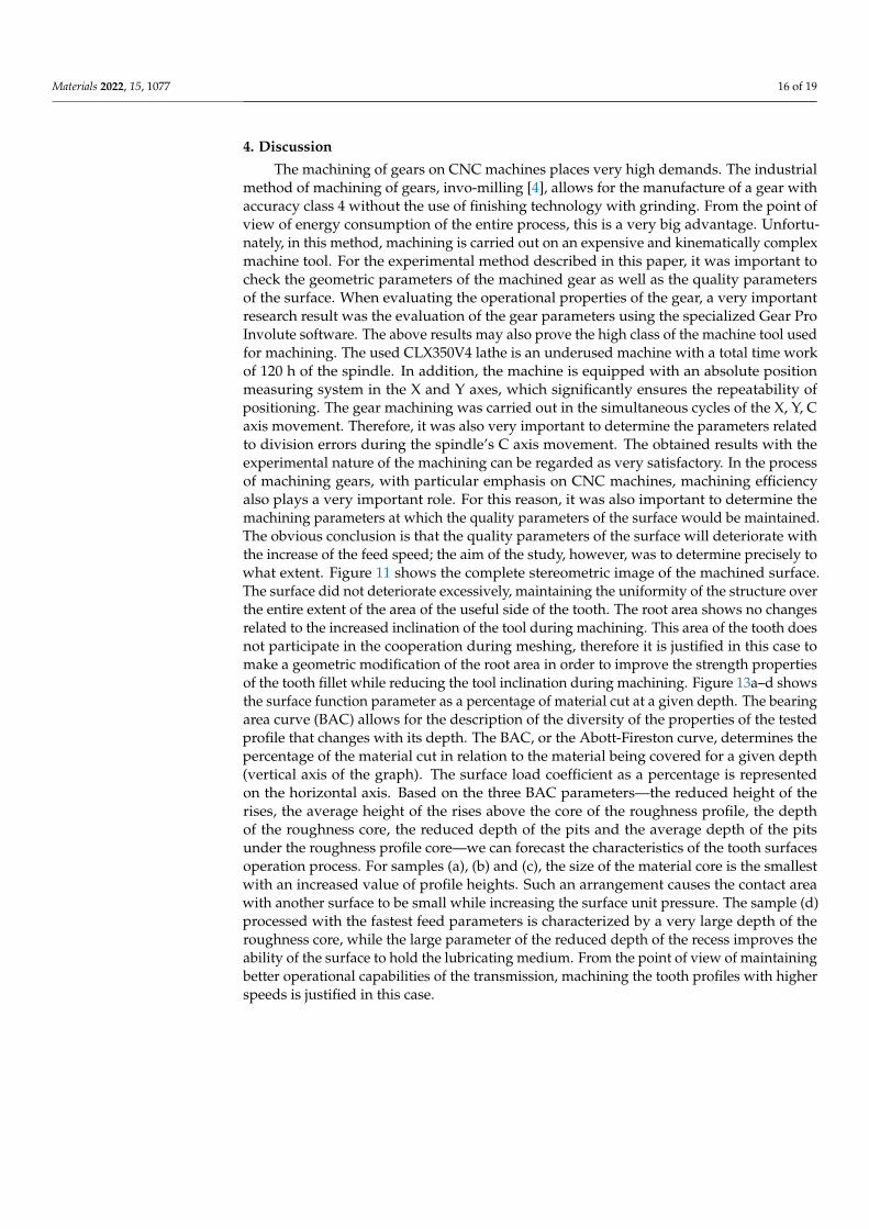
The main profile parameters are defined in the ISO 4287 standard [31]. Measuredprofile is a series of height values as a function of the lateral position. Figure 12 shows theroughness profile from the fillet area to the tooth head for the four analysed machiningvariants. The roughness profile distribution is constant in all cases, only in the case of toothfillet area (Figure 12b), there was a local, abnormal deterioration of the surface condition.This may result from the enlargement of the area of the tool contact zone, which was oftenaccompanied by chatters during machining. The heights are references by conventionfrom the mean line, which is calculated as the mean value of all heights. Figure 13 showsthe functional parameters of the surface Rmr as the material ratio at a given depth. Thisparameter gives the percentage of material cut at a given depth from the top of the profile.The reference may also be taken from the centre line or another reference height.
Materials 2022, 15, x FOR PEER REVIEW 14 of 19
Figure 10. The measured roughness profile Ra and Rz parameters, measured longitudinally to the
tooth profile. The results of machining time as a function of feed rate.
A number of measurements were made, including the surface roughness parameters
Ra and Rz, in order to better represent local changes in the surface structure (Figure 10).
The machining process was carried out within the normative range of the cutting param-
eters. It can be noticed here that the roughness parameter Ra, in the entire extent of its
changes, does not present above-normative deviations. Roughness changes in the range
of feed speeds from 200 to 1000 mm/min are slight and acceptable for maintaining a high-
quality machining process. The results of the measurement of the roughness parameter
Rz are also satisfactory; it is very important for the assessment of sudden increase of local
changes in the roughness profiles caused by phenomena in the machining process. The
increase in the Rz parameter value is correct in relation to the obtained Ra parameter re-
sults. The stereometric distribution of the machined tooth area was also determined (Fig-
ure 11). The microgeometric structure of the top layer was also assessed, and the meas-
urement was made in the middle section of the tooth perpendicular to the processing di-
rection. Figure 12 shows the original structure of the surface profile; the shape of the in-
volute tooth profile was filtered.
Figure 11. A stereometric distribution of the machined tooth—sample 4, machined with a feed speed
of Vf = 1800 mm/min.
Figure 11. A stereometric distribution of the machined tooth—sample 4, machined with a feed speedof Vf = 1800 mm/min.
Materials 2022, 15, x FOR PEER REVIEW 15 of 19
Figure 12. The roughness parameter profile Ra measured in the direction of the tooth profile. (a) feed rate Vf = 200 mm/min, (b) feed rate Vf = 600 mm/min, (c) feed rate Vf = 1000 mm/min, (d) feed rate Vf = 1800 mm/min.
The main profile parameters are defined in the ISO 4287 standard [31]. Measured profile is a series of height values as a function of the lateral position. Figure 12 shows the roughness profile from the fillet area to the tooth head for the four analysed machining variants. The roughness profile distribution is constant in all cases, only in the case of tooth fillet area (Figure 12b), there was a local, abnormal deterioration of the surface con-dition. This may result from the enlargement of the area of the tool contact zone, which was often accompanied by chatters during machining. The heights are references by con-vention from the mean line, which is calculated as the mean value of all heights. Figure 13 shows the functional parameters of the surface Rmr as the material ratio at a given depth. This parameter gives the percentage of material cut at a given depth from the top of the profile. The reference may also be taken from the centre line or another reference height.
Figure 12. Cont.
Materials 2022, 15, 1077 15 of 19
Materials 2022, 15, x FOR PEER REVIEW 15 of 19
Figure 12. The roughness parameter profile Ra measured in the direction of the tooth profile. (a) feed rate Vf = 200 mm/min, (b) feed rate Vf = 600 mm/min, (c) feed rate Vf = 1000 mm/min, (d) feed rate Vf = 1800 mm/min.
The main profile parameters are defined in the ISO 4287 standard [31]. Measured profile is a series of height values as a function of the lateral position. Figure 12 shows the roughness profile from the fillet area to the tooth head for the four analysed machining variants. The roughness profile distribution is constant in all cases, only in the case of tooth fillet area (Figure 12b), there was a local, abnormal deterioration of the surface con-dition. This may result from the enlargement of the area of the tool contact zone, which was often accompanied by chatters during machining. The heights are references by con-vention from the mean line, which is calculated as the mean value of all heights. Figure 13 shows the functional parameters of the surface Rmr as the material ratio at a given depth. This parameter gives the percentage of material cut at a given depth from the top of the profile. The reference may also be taken from the centre line or another reference height.
Figure 12. The roughness parameter profile Ra measured in the direction of the tooth profile. (a) feedrate Vf = 200 mm/min, (b) feed rate Vf = 600 mm/min, (c) feed rate Vf = 1000 mm/min, (d) feed rateVf = 1800 mm/min.
Materials 2022, 15, x FOR PEER REVIEW 16 of 19
Figure 13. The material ratio as a function of the height, Abott-Fireston curve. (a) feed rate Vf = 200
mm/min, (b) feed rate Vf = 600 mm/min, (c) feed rate Vf = 1000 mm/min, (d) feed rate Vf = 1800
mm/min.
4. Discussion
The machining of gears on CNC machines places very high demands. The industrial
method of machining of gears, invo-milling [4], allows for the manufacture of a gear with
accuracy class 4 without the use of finishing technology with grinding. From the point of
view of energy consumption of the entire process, this is a very big advantage. Unfortu-
nately, in this method, machining is carried out on an expensive and kinematically com-
plex machine tool. For the experimental method described in this paper, it was important
to check the geometric parameters of the machined gear as well as the quality parameters
of the surface. When evaluating the operational properties of the gear, a very important
research result was the evaluation of the gear parameters using the specialized Gear Pro
Involute software. The above results may also prove the high class of the machine tool
used for machining. The used CLX350V4 lathe is an underused machine with a total time
work of 120 h of the spindle. In addition, the machine is equipped with an absolute posi-
tion measuring system in the X and Y axes, which significantly ensures the repeatability
of positioning. The gear machining was carried out in the simultaneous cycles of the X, Y,
C axis movement. Therefore, it was also very important to determine the parameters re-
lated to division errors during the spindle’s C axis movement. The obtained results with
the experimental nature of the machining can be regarded as very satisfactory. In the pro-
cess of machining gears, with particular emphasis on CNC machines, machining effi-
ciency also plays a very important role. For this reason, it was also important to determine
the machining parameters at which the quality parameters of the surface would be main-
tained. The obvious conclusion is that the quality parameters of the surface will deterio-
rate with the increase of the feed speed; the aim of the study, however, was to determine
Figure 13. The material ratio as a function of the height, Abott-Fireston curve. (a) feed rateVf = 200 mm/min, (b) feed rate Vf = 600 mm/min, (c) feed rate Vf = 1000 mm/min, (d) feed rateVf = 1800 mm/min.
Materials 2022, 15, 1077 16 of 19
4. Discussion
The machining of gears on CNC machines places very high demands. The industrialmethod of machining of gears, invo-milling [4], allows for the manufacture of a gear withaccuracy class 4 without the use of finishing technology with grinding. From the point ofview of energy consumption of the entire process, this is a very big advantage. Unfortu-nately, in this method, machining is carried out on an expensive and kinematically complexmachine tool. For the experimental method described in this paper, it was important tocheck the geometric parameters of the machined gear as well as the quality parametersof the surface. When evaluating the operational properties of the gear, a very importantresearch result was the evaluation of the gear parameters using the specialized Gear ProInvolute software. The above results may also prove the high class of the machine tool usedfor machining. The used CLX350V4 lathe is an underused machine with a total time workof 120 h of the spindle. In addition, the machine is equipped with an absolute positionmeasuring system in the X and Y axes, which significantly ensures the repeatability ofpositioning. The gear machining was carried out in the simultaneous cycles of the X, Y, Caxis movement. Therefore, it was also very important to determine the parameters relatedto division errors during the spindle’s C axis movement. The obtained results with theexperimental nature of the machining can be regarded as very satisfactory. In the processof machining gears, with particular emphasis on CNC machines, machining efficiencyalso plays a very important role. For this reason, it was also important to determine themachining parameters at which the quality parameters of the surface would be maintained.The obvious conclusion is that the quality parameters of the surface will deteriorate withthe increase of the feed speed; the aim of the study, however, was to determine precisely towhat extent. Figure 11 shows the complete stereometric image of the machined surface.The surface did not deteriorate excessively, maintaining the uniformity of the structure overthe entire extent of the area of the useful side of the tooth. The root area shows no changesrelated to the increased inclination of the tool during machining. This area of the tooth doesnot participate in the cooperation during meshing, therefore it is justified in this case tomake a geometric modification of the root area in order to improve the strength propertiesof the tooth fillet while reducing the tool inclination during machining. Figure 13a–d showsthe surface function parameter as a percentage of material cut at a given depth. The bearingarea curve (BAC) allows for the description of the diversity of the properties of the testedprofile that changes with its depth. The BAC, or the Abott-Fireston curve, determines thepercentage of the material cut in relation to the material being covered for a given depth(vertical axis of the graph). The surface load coefficient as a percentage is representedon the horizontal axis. Based on the three BAC parameters—the reduced height of therises, the average height of the rises above the core of the roughness profile, the depthof the roughness core, the reduced depth of the pits and the average depth of the pitsunder the roughness profile core—we can forecast the characteristics of the tooth surfacesoperation process. For samples (a), (b) and (c), the size of the material core is the smallestwith an increased value of profile heights. Such an arrangement causes the contact areawith another surface to be small while increasing the surface unit pressure. The sample (d)processed with the fastest feed parameters is characterized by a very large depth of theroughness core, while the large parameter of the reduced depth of the recess improves theability of the surface to hold the lubricating medium. From the point of view of maintainingbetter operational capabilities of the transmission, machining the tooth profiles with higherspeeds is justified in this case.
Materials 2022, 15, 1077 17 of 19
5. Conclusions
In summary, it can be stated that the experimental method of gear machining on anumerically controlled lathe with the use of driven tools presented in this paper has anumber of advantages:
• Machining with a tool that is not geometrically related to the contour being machined,in our case, as a two-parameter circumference, is an excellent alternative to complicatedand expensive hobbing methods.
• This method allows the use of any modifications of the machined tooth profile; more-over, the processing of profiles other than involute with non-standard modules is nota problem in this case.
The main problem of the application and further development of non-commercialmethods of gear machining is their insufficient efficiency combined with low quality. In theanalysed case, the conducted research proves that it does not have to be this way:
• This method guarantees very efficient machining and at the same time guarantees thequality of the process. The graph in Figure 11, on the basis of the performed machiningsimulations, presents the time dependence in the function of feed changes. As canbe seen, the feed rate is the biggest factor influencing the efficiency of the entire gearmachining process.
• The obtained machining time of less than three minutes for the cutting variant at afeed rate of 1800 mm/min is an excellent result, and the analysis of the quality of themachined surface in this case is also very good.
• The analysed machining process has significant reserves in terms of productivity; thedriven tool holder with a maximum rotational speed of 4500 rpm significantly limitedthe feed rate used in machining.
The quality of the gear is determined by the lowest manufacturing accuracy of one ofits components. The tested gear wheel, in terms of geometric and surface quality, obtainedsatisfactory results:
• The accuracy of the machined profile form deviation in the entire processing did notexceed average value of 10 µm, while assessing the tooth line, the basis average errorwas 5 µm.
• The measurement of the stereometry of the surface layer showed an even distribu-tion of its structure. The roughness and material ratio indicators showed correctdifferentiation in relation to the applied changes in machining parameters.
The presented work proved that it is possible to machine gears on a basic CNC lathe,and the obtained results of geometric and surface accuracy, while maintaining technologicaldiscipline, may be fully satisfactory. This machining method can be used not only formachining external gearing, but also for the more technologically demanding processingof internal gears. It can also allow the production of gears with any modification to thetooth profile.
The method of gear machining described in the work has been submitted to the PolishPatent Office as a patent claim under the number P.439202.
Funding: This research received no external funding.
Institutional Review Board Statement: Not applicable.
Informed Consent Statement: Not applicable.
Data Availability Statement: Data are contained within the article.
Conflicts of Interest: The author declares no conflict of interest.
Materials 2022, 15, 1077 18 of 19
Abbreviations
α pressure angle
α0angle between the radius of the involute’s initial point and the radius of the consideredpoint of the involute
α0 arc angle in involute function
ϕangle between the ordinate and the leading radius of the point of tangency normalto the outline
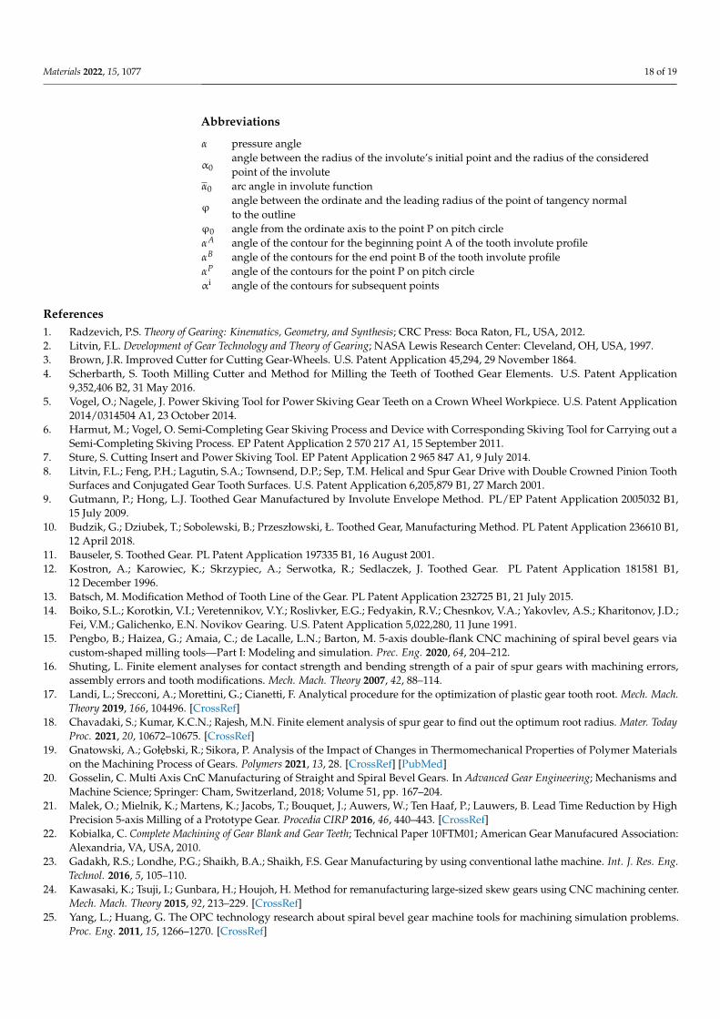
ϕ0 angle from the ordinate axis to the point P on pitch circleαA angle of the contour for the beginning point A of the tooth involute profileαB angle of the contours for the end point B of the tooth involute profileαP angle of the contours for the point P on pitch circleαi angle of the contours for subsequent points
References1. Radzevich, P.S. Theory of Gearing: Kinematics, Geometry, and Synthesis; CRC Press: Boca Raton, FL, USA, 2012.2. Litvin, F.L. Development of Gear Technology and Theory of Gearing; NASA Lewis Research Center: Cleveland, OH, USA, 1997.3. Brown, J.R. Improved Cutter for Cutting Gear-Wheels. U.S. Patent Application 45,294, 29 November 1864.4. Scherbarth, S. Tooth Milling Cutter and Method for Milling the Teeth of Toothed Gear Elements. U.S. Patent Application
9,352,406 B2, 31 May 2016.5. Vogel, O.; Nagele, J. Power Skiving Tool for Power Skiving Gear Teeth on a Crown Wheel Workpiece. U.S. Patent Application
2014/0314504 A1, 23 October 2014.6. Harmut, M.; Vogel, O. Semi-Completing Gear Skiving Process and Device with Corresponding Skiving Tool for Carrying out a
Semi-Completing Skiving Process. EP Patent Application 2 570 217 A1, 15 September 2011.7. Sture, S. Cutting Insert and Power Skiving Tool. EP Patent Application 2 965 847 A1, 9 July 2014.8. Litvin, F.L.; Feng, P.H.; Lagutin, S.A.; Townsend, D.P.; Sep, T.M. Helical and Spur Gear Drive with Double Crowned Pinion Tooth
Surfaces and Conjugated Gear Tooth Surfaces. U.S. Patent Application 6,205,879 B1, 27 March 2001.9. Gutmann, P.; Hong, L.J. Toothed Gear Manufactured by Involute Envelope Method. PL/EP Patent Application 2005032 B1,
15 July 2009.10. Budzik, G.; Dziubek, T.; Sobolewski, B.; Przeszłowski, Ł. Toothed Gear, Manufacturing Method. PL Patent Application 236610 B1,
12 April 2018.11. Bauseler, S. Toothed Gear. PL Patent Application 197335 B1, 16 August 2001.12. Kostron, A.; Karowiec, K.; Skrzypiec, A.; Serwotka, R.; Sedlaczek, J. Toothed Gear. PL Patent Application 181581 B1,
12 December 1996.13. Batsch, M. Modification Method of Tooth Line of the Gear. PL Patent Application 232725 B1, 21 July 2015.14. Boiko, S.L.; Korotkin, V.I.; Veretennikov, V.Y.; Roslivker, E.G.; Fedyakin, R.V.; Chesnkov, V.A.; Yakovlev, A.S.; Kharitonov, J.D.;
Fei, V.M.; Galichenko, E.N. Novikov Gearing. U.S. Patent Application 5,022,280, 11 June 1991.15. Pengbo, B.; Haizea, G.; Amaia, C.; de Lacalle, L.N.; Barton, M. 5-axis double-flank CNC machining of spiral bevel gears via
custom-shaped milling tools—Part I: Modeling and simulation. Prec. Eng. 2020, 64, 204–212.16. Shuting, L. Finite element analyses for contact strength and bending strength of a pair of spur gears with machining errors,
assembly errors and tooth modifications. Mech. Mach. Theory 2007, 42, 88–114.17. Landi, L.; Srecconi, A.; Morettini, G.; Cianetti, F. Analytical procedure for the optimization of plastic gear tooth root. Mech. Mach.
Theory 2019, 166, 104496. [CrossRef]18. Chavadaki, S.; Kumar, K.C.N.; Rajesh, M.N. Finite element analysis of spur gear to find out the optimum root radius. Mater. Today
Proc. 2021, 20, 10672–10675. [CrossRef]19. Gnatowski, A.; Gołebski, R.; Sikora, P. Analysis of the Impact of Changes in Thermomechanical Properties of Polymer Materials
on the Machining Process of Gears. Polymers 2021, 13, 28. [CrossRef] [PubMed]20. Gosselin, C. Multi Axis CnC Manufacturing of Straight and Spiral Bevel Gears. In Advanced Gear Engineering; Mechanisms and
Machine Science; Springer: Cham, Switzerland, 2018; Volume 51, pp. 167–204.21. Malek, O.; Mielnik, K.; Martens, K.; Jacobs, T.; Bouquet, J.; Auwers, W.; Ten Haaf, P.; Lauwers, B. Lead Time Reduction by High
Precision 5-axis Milling of a Prototype Gear. Procedia CIRP 2016, 46, 440–443. [CrossRef]22. Kobialka, C. Complete Machining of Gear Blank and Gear Teeth; Technical Paper 10FTM01; American Gear Manufacured Association:
Alexandria, VA, USA, 2010.23. Gadakh, R.S.; Londhe, P.G.; Shaikh, B.A.; Shaikh, F.S. Gear Manufacturing by using conventional lathe machine. Int. J. Res. Eng.
Technol. 2016, 5, 105–110.24. Kawasaki, K.; Tsuji, I.; Gunbara, H.; Houjoh, H. Method for remanufacturing large-sized skew gears using CNC machining center.
Mech. Mach. Theory 2015, 92, 213–229. [CrossRef]25. Yang, L.; Huang, G. The OPC technology research about spiral bevel gear machine tools for machining simulation problems.
Proc. Eng. 2011, 15, 1266–1270. [CrossRef]

Materials 2022, 15, 1077 19 of 19
26. Chung-Yu, T. Power-skiving tool design method for interference-free involute internal gear cutting. Mech. Mach. Theory 2021, 164,1–42.
27. Gołebski, R. Parametric programming of CNC machine tools. In Proceedings of the 4th International Conference on Computingand Solutions in Manufacturing Engineering 2016, Transilvania University of Bras, ov, Brasov, Romania, 3–4 November 2016;Volume 94.
28. Gołebski, R.; Boral, P. Study of machining of gears with regular and modified outline using CNC machine tools. Arch. Mater.2021, 14, 2913. [CrossRef] [PubMed]
29. Perschmann. Tools Guide Catalogue. Available online: https://www.hoffmann-group.com/GB/en/houk/Mono-machining/Solid-carbide-milling-cutters/GARANT-Master-Alu-solid-carbide-milling-cutter%2C-HPC-HPC-uncoated/p/203208-6 (ac-cessed on 4 November 2021).
30. ISO 1328-1:2015; Cylindrical Gears—ISO System of Flank Tolerance Classification—Part 1: Definitions and Allowable Values ofDouble Flank Radial Composite Deviations; PKN: Warsaw, Poland, 2015.
31. ISO 4287:1997; Geometrical Product Specifications (GPS)—Surface Texture: Profile Method—Terms, Definitions and SurfaceTexture Parameters; PKN: Warsaw, Poland, 1999.


