Embed Size (px)
Citation preview
AN EXPERIMENTAL STUDY IN THE DESIGN OFA SMALL DOWN-DRAFT GAS FIRED KILN
by
MAURICE WINSTON BERGGREN
B. F. A. , Bethany College, 1962
A MASTER'S THESIS
submitted in partial fulfillment of the
requirements fox the degree
MASTER OF ARTS
Department of Art
KANSAS STATE UNIVERSITYManhattan, Kansas
1968
Approved by:
Major Pr
7/
B</7<£/ TABLE OF CONTENTS
INTRODUCTION 1
LIST OF MATERIALS USED 4
CONSTRUCTION OF FACILITIES 5
Kiln Shelf Space 5
The Foundation 6
Insulating the Kiln Floor 7
The Kiln Floor 7
The Baffle Wall 9
Side Walls and Back 12
Spy Holes and Plugs 12
Burner Ports 14
The Door 14
The Ceiling 14
The Chimney 19
Kiln House 21
Gas Lines, Burners and Firing Equipment 23
FIRING PROCEDURE 27
Time and Temperature 27
Kiln Log 27
EVALUATION OF KILN DESIGN 30
EVALUATION OF THESIS POTTERY 36
ACKNOWLEDGEMENTS 59
BIBLIOGRAPHY 60
INTRODUCTION
A kiln is the most necessary tool fox the potter's studio.
A variety of ceramic ware can be made with one's hands, but a
kiln is necessary if the work is to be finished. The idea of a
kiln is to generate heat in the most efficient and economical
fashion and to transfer that heat to the ware.
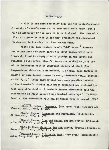
Kilns date into history nearly 7,000 years. * Numerous
variations have developed since the first kilns, which were
"probably fired by simply placing pottery on the ground and
building a fire around them. "2 Among the variations, the use
of the down-draft kiln is important because of the higher
temperatures which could be reached. In China, kiln firings of
2192° F or more became common in early times—as early, perhaps,
as 500 B. C. These temperatures were made possible because
of the down-draft chamber kiln which conserved and utilized the
heat more effectively. A semi-continuous down-draft kiln was
established in Japan nearly three hundred years ago. 4 In North
America, the down-draft kiln can be traced back to around 1875. 5
Winston^lnc?. !^)! ?: Wf*** ^ "* H°U' ^"^ and
Chllton^iogyg: ST"™ ** ***** <"*l«*lphi..
i»< ou??xiel
^Rhod
!S» 9* a-
v and Glazes for. £he Potter . (Philadel-phia* Chilton Co., 1957TTp. 58.
R.«n.++4?!l
th & Hom«» gSSSffiics for. ihe. Potter. (Peoria t Charles A.Bennett Co., Inc., 1953 J, p. 173T^
A»t. T^8rn?^M each» &JFi*ti£& Baak* (New York: TransAtlanticArts, Inc., 1951), pp. 185-6.
There are three ways in which heat may be transferred from
ignited fuel to the ware: by conduction, convection, and radiation.
All three methods are made use of in the kiln,though the potter relies less on radiation than onconduction and the circulation of air currents.Heat is spread from one to another of the closelypacked pieces from the walls of the kiln... to thewares within.
The down-draft kiln is unique when compared to the up-draft
kiln, in that the longer path of air currents commands a more
complete use of the heat. The fire reaches the main body of the
kiln in much the same manner, over a baffle wall, 7 but does not
escape through an opening at the top because the ceiling is
closed. The heat must pass through the main portion of the kiln
as it is being attracted by the flue in the floor. Provided the
burners, air intake, and chimney are adequate, a uniform heat can
be obtained by adjustments in the height of the baffle wall, the
opening into the chimney, or the regulation of the damper. 8
The purpose of this study was to design a small down-draft
kiln for the learning experience and use of the writer, and to
provide plans of it's construction for the benefit of other
potters. Most potters know what they want in performance from a
kiln, but they may lack the engineering background to design
according to those wants, or they may not have the time to
experiment for them.
6Ibid .. pp. 167-8.
.m v?^f te*m* baff le waH and bag wall are used interchange-
ssjt^ss^-iSsn.W11- (New York ' Hoit ' Rinehart and
8IJb£d.. PP. 230-1.
This study of a five and four-tenths cubic foot dry brick
kiln is a summation of experimentation, construction procedures,
and conclusions incorporating the advice and opinions of other
potters and a mechanical engineer. The size of this kiln lends
itself to the potter who works on a small scale or to potters
who work other than full time with ceramics.
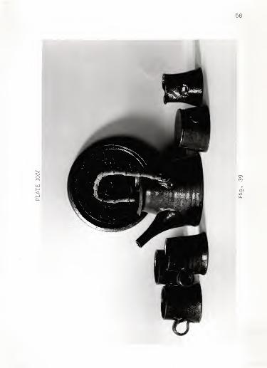
A photographic review of the finished products in clay
has been supplied as an example of the results of the numerous
firings which were done with different constructional variations
in designing this kiln. The primary aim of this section of the
thesis was to achieve a personal ideal of the aesthetic quality
of the glaze and body of the pottery.
4
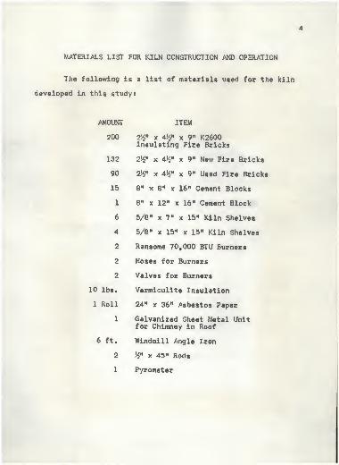
MATERIALS LIST FOR KILN CONSTRUCTION AND OPERATION
The following i s a list of materials used for the kiln
developed in this study:
AMOUNT ITEM
200 2^" x 4^M x 9" K2600Insulating Fire Bricks
132 2%n x 4 {/2" x 9" New Fire Bricks
90 2^« x 4J£« x 9 m Used Fire Bricks
15 8" x 8" x 16" Cement Blocks
1 8" x 12" x 16" Cement Block
6 5/8" x 7" x 15" Kiln Shelves
4 5/8" x 15" x 15" Kiln Shelves
2 Ransome 70,000 BTU Burners
2 Hoses for Burners
2 Valves for Burners
10 lbs. Vermiculite Insulation
1 Roll 24" x 36" Asbestos Paper
1 Galvanized Sheet Metal Unitfor Chimney in Roof
6 ft. Windmill Angle Iron
2 >$" x 45" Rods
1 Pyrometer
CONSTRUCTION OF FACILITIES
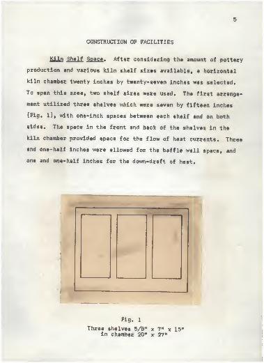
Kiln Shelf Space . After considering the amount of pottery
production and various kiln shelf sizes available, a horizontal
kiln chamber twenty inches by twenty-seven inches was selected.
To span this area, two shelf sizes were used. The first arrange-
ment utilized three shelves which were seven by fifteen inches
(Fig. 1), with one-inch spaces between each shelf and on both
sides. The space in the front and back of the shelves in the
kiln chamber provided space for the flow of heat currents. Three
and one-half inches were allowed for the baffle wall space, and
one and one-half inches for the down-draft of heat.
Fig. 1
Three shelves 5/8 M x 7" x 15"in chamber 20" x 27"
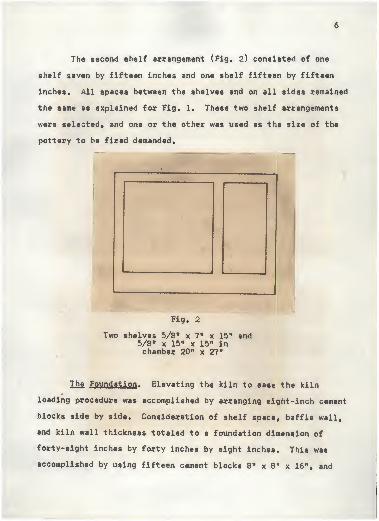
The second shelf arrangement (Fig. 2) consisted of one
shelf seven by fifteen inches and one shelf fifteen by fifteen
inches. All spaces between the shelves and on all sides remained
the same as explained for Fig. 1. These two shelf arrangements
were selected, and one or the other was used as the size of the
pottery to be fired demanded.
Fig. 2
Two shelves 5/8" x 7 H x 15" and5/8" x 15" x 15" inchamber 20" x 27"
Ihg Foundation . Elevating the kiln to ease the kiln
loading procedure was accomplished by arranging eight-inch cement
blocks side by side. Consideration of shelf space, baffle wall,
and kiln wall thickness totaled to a foundation dimension of
forty-eight inches by forty inches by eight inches. This was
accomplished by using fifteen cement blocks 8" x 8" x 16", and
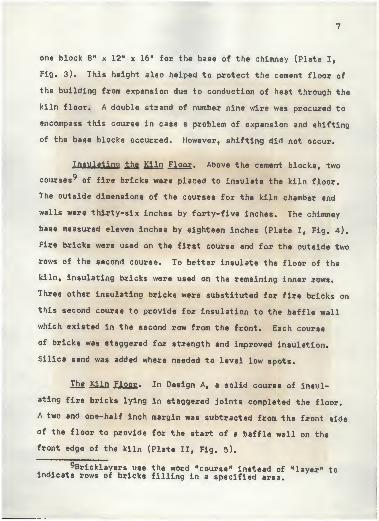
one block 8" x 12" x 16" for the base of the chimney (Plate I,
Fig. 3). This height also helped to protect the cement floor of
the building from expansion due to conduction of heat through the
kiln floor. A double strand of number nine wire was procured to
encompass this course in case a problem of expansion and shifting
of the base blocks occurred. However, shifting did not occur.
Insulating the Kiln Floor . Above the cement blocks, two
courses9 of fire bricks were placed to insulate the kiln floor.
The outside dimensions of the courses for the kiln chamber and
walls were thirty-six inches by forty-five inches. The chimney
base measured eleven inches by eighteen inches (Plate I, Fig. 4).
Fire bricks were used on the first course and for the outside two
rows of the second course. To better insulate the floor of the
kiln, insulating bricks were used on the remaining inner rows.
Three other insulating bricks were substituted for fire bricks on
this second course to provide for insulation to the baffle wall
which existed in the second row from the front. Each course
of bricks was staggered for strength and improved insulation.
Silica sand was added where needed to level low spots.
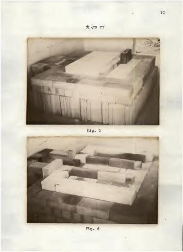
The Kiln Floor . In Design A, a solid course of insul-
ating fixe bricks lying in staggered joints completed the floor.
A two and one-half inch margin was subtracted from the front side
of the floor to provide for the start of a baffle wall on the
front edge of the kiln (Plate II, Fig. 5).
^Bricklayers use the word "course" instead of "layer" toindicate rows of bricks filling in a specified area.
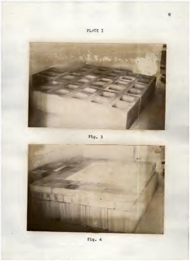
In Floor Design B, the top layer of the kiln floor was
constructed in a design to provide for the channeling of the
heat flow to the back of the kiln. These channels existed on
each side and were two and one-half inches by four and one-half
inches by eighteen inches. The flue was also channeled into the
floor. It's dimensions were two and one-half inches by nine
inches by thirty-one and one-half inches, and it was exposed to
the kiln chamber in the front (Plate II, Fig. 6).
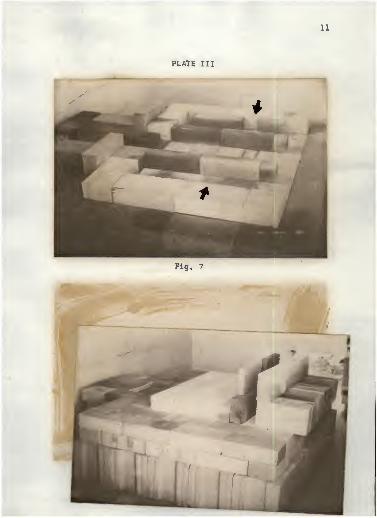
In Floor Design C, the kiln floor exposed a chimney flue
and burner ports with a variation from Design B. This change
included two openings on each side measuring one inch by four and
one-half inches (after the kiln shelves were in place) for the
purpose of directing a portion of heat to the side walls of the
kiln. These openings were on the left and right side of the
kiln. (Note arrows, Plate III, Fig. 7).
2M Baffle Wall . Design A. In the two and one-half inch
space provided in the kiln floor, a baffle wall to direct the
heat up in the kiln chamber consisted of a partial wall of four
insulating fire bricks thirteen and one-half inches high. Each
of the insulating bricks used was one and one-fourth inch by
four and one-half inches by nine inches. The bricks were split
to the one and one-fourth inch thickness to conserve kiln chamber
space (Plate III, Fig. 8). A fire brick was selected for the
bottom course of the baffle wall for heat absorption. An eighty-
degree angle brick, to ease the directional change of the flames,
was selected.
11
PLATE III
Fig. 7
12
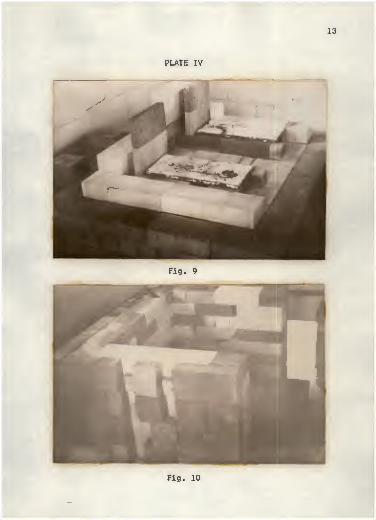
Baffle Wall Design B. With the heat channeled to the back
of the kiln, the back functioned to turn the flames upward, A
baffle wall, two and one-half inches from the back wall, consist-
ing of two insulating bricks laid on their sides one above the
other, formed a solid wall which continued the flame upward for
nine more inches (Plate IV, Fig. 9).
Side Walls and Back . The inside cubic dimension of this
kiln is seven and one-half feet, with an actual capacity for
five and four-tenths cubic feet of pottery. In consideration of
this size, and after consultation with Mr. Angelo Garzio,
(Professor of Art at Kansas State University), a seven-inch
thickness of insulation was determined to be ample to contain
the heat for a cone 8 firing.
The exterior layer of brick was of fire brick and laid on
edge. Fire brick was selected for two reasons i (1) it was less
expensive, and (2) it was more durable.
The interior layer was of insulating fire brick lying
flat. The over-all height of twenty-two and one-half inches was
accomplished with five courses of exterior fire bricks on edge,
and nine courses of insulating bricks lying flat to accomplish
a wall width of seven inches (Plate IV, Fig. 10).
Sfiy. Holes and Plugs . Eight spy holes were included in the
structure; five on one side for specific analyzation of the kiln
interior, two on the other side for general analyzation, and one
leading to the flue opening. The holes were cut out of insulating
13
PLATE IV
Fig. 9
Fig. 10
14
brick of the interior wall and generally measured two and one-half
inches by two inches by four and one-half inches (Plate V,
Fig. 11). This two and one-half inch measurement diagonaled to
two inches to provide a loosening of the spy plug st its slight-
est extraction and an ever-tightening wedge when inserted.
A one-fourth inch space was allowed in a corner of the
layer that contained each spy hole. This allowed the plug to be
extended one-half to one-fourth inch when in place for ease in
grasping (Plate V f Fig. 11).
Burner Ports . To facilitate three-inch diameter burners,
the two ports consisted of openings in the base of the doorway
from the first course of exterior brick that stood on edge
(Plate V, Fig. 12). These openings measured three and one-half
inches by four and one-half inches by nine inches, which was
more than ample for providing secondary air to the flame. To
reduce this amount, aluminum foil was used.
The Door . This segment of the kiln was rebuilt with each
firing. It consisted of the interior wall of insulation brick
stacked on edge to provide a wider kiln interior space, and the
exterior wall of fire brick lying flat to make the wall thickness
total seven inches (Plate VI, Fig. 13). The interior layer fit-
ted inside the inside walls, the exterior layer fitted inside the
exterior walls as they joined at each front corner of the kiln,
thus providing overlapping corner joints.
The Ceiling . A four-inch rising arch was used to close
15
PLATE V
Fig. 11
Fig. 12
16
the top of this unit. Two designs were used for the study.
In Ceiling Design A, four and one-half bricks cut at equal
eighty-degree angles spanned the interior width of twenty-seven
inches and overlapped the interior wall for a total of thirty-six
inches. Each end of this arch rested on the interior side walls
and was held there by a windmill leg angle iron with a one-half
inch rod in the front and back. Eight rows of four and one-half
bricks completed the ceiling to the top interior of the back wall
and to the top interior of the door (Plate VI, Fig. 14). With
only four and one-half inches of thickness to the ceiling, more
light-weight insulation was needed to be consistent with other
parts of the kiln. Asbestos paper (to prevent dust from the
next insulation material from sifting through during expansion
and contraction) was carefully cut and fitted to the top of the
arch. The front row of arch brick was extended in height two and
one-half more inches with scrap insulating brick, thus forming a
containing wall for two and one-half to three inches of house-
fill vermiculite. The side containing wall consisted of two hard
one-fourth inch asbestos sheets and the back wall enclosed the
vermiculite layer. This back wall was a nine inch extension of
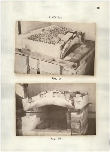
the interior back wall of the fire box (Plate VII, Fig. 15).
Ceiling Design B. (Plate VII, Fig. 16). This variation in
design was a ninety degree rotation of the structure used in
Design A. Since this unit was not square, the arch weight was
transferred from the interior wall to the exterior wall of fire
brick. Two additional rows of bricks that made up the arch were
added to the arch width to span the twenty-seven inch inside
PLATE VI
17
Fig. 13
Fig. 14
18
PLATE VII
Fig. 15
Fig. 16
19
dimension. A side of the kiln was used to serve as a door for
this change in direction of the arch, since the previously
discussed front supported one side of the ceiling arch.
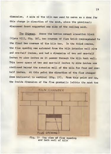
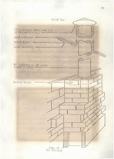
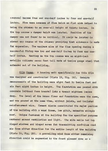
The Chimney . Above the bottom cement elevation block
(Plate VIII, Fig. 18), two courses of fire brick corresponded to
the first two courses of the kiln box. In the third course,
the flue opening was extended from the kiln interior wall nine
and one-half inches, and had a dimension of two and one-half
inches by nine inches as it passed through the kiln back wall.
This inner space of two and one-half inches by nine inches was
continued beyond the exterior wall of the kiln for four and one-
half inches. At this point the direction of the flue changed
from horizontal to vertical (Fig. 17). From this point and up,
the inside dimension of the flue gradually (within the next two
KILN CHAMBER
FLUE OPENING
Fig. 17 Top view of flue openingand back wall of kiln
20
PLATE VI I
;
5" clearance from flue topto Chinaman's cap -
—
roof shingles
notal flare
roof sheetinq
-
. •
7*-<#
8" cylinder of 12 gaugesteel 7' tall
damper brick
Fig. 18 /The Chimney
21
courses) became four and one-half inches by four and one-half
inches. Five more courses of fire brick on flat side helped to
bring the chimney to an over-all height of thirty inches. In
the top course a damper brick was located. Position of the
damper was not found to be critical. It could be located in
almost any course of the chimney providing that allowance is made
for expansion. The maximum size of the flue opening during a
successful firing was two and one-half inches by four and one-
half inches. Resting on the top course was an eight-inch
metallic cylinder seven feet tall made of twelve gauge steel that
extended out of the building.
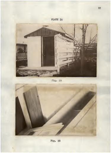
Kiln House . A housing unit specifically for this kiln
was designed and constructed (Plate IX, Fig. 19). Outside
measurements of the building were eight feet by twelve feet and
six feet eight inches in height. The foundation was poured with
concrete (without form boards) into a trench eighteen inches
deep. The level of the house floor and foundation were the same,
and was poured at the same time, without Joints, and included
reinforcement wire. Cement blocks constituted the major portion
of the building with a wood frame, low pitch, asbestos shingle
roof. Unique features of the building for the specified purpose
centered around ventilation and light. The side walls had top
hinged windows and hinged eaves for transmitting roof-line cool
air from either direction for the entire length of the building
(Plate IX, Fig. 20). A prevailing wind from either remaining
direction could be augmented by the front glassed door or a
22
PLATE IX
Fig. 19
Fig. 20
23
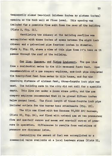
temporarily closed two-block (sixteen inches by sixteen inches)
opening on the back wall at floor level. This opening was
included for a possible flue exit from the rear of the building
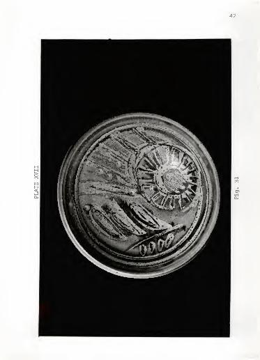
(Plate X, Fig. 21).
Ventilating the chimney at the building roofline was
accomplished with three inches of space between the eight inch
chimney and a galvanized pipe fourteen inches in diameter.
Plate X, Fig. 22, shows a view of this pipe from it's base as it
passes through the roof of the building.
Gas line , Burners . and Firing Equipment , The gas line
from a residential meter to the kiln measured forty feet. Upon
recommendation of a gas company employee, one-inch pipe completed
the twenty-four feet from meter to kiln house, and for the
remaining distance of sixteen feet, three-fourths inch pipe was
used. The building code in the city did not call for a specific
depth. This line ran under a loose stone patio, and the gas
company employee recommended that it be placed fifteen inches
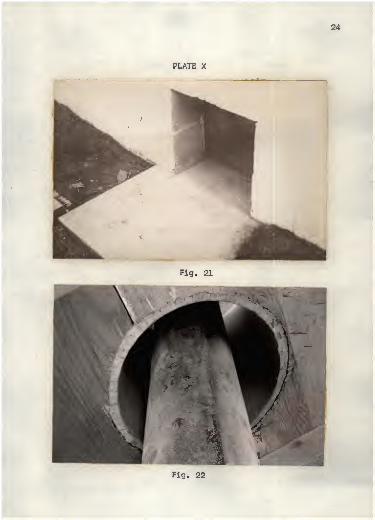
below ground level. The final length of three-fourths inch pipe
included outlets for the burner hose attachments (Fig. 23).
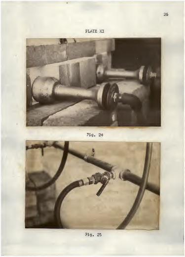
The kiln was fired with two Ransome 70,000 BTU burners,
(Plate XI, Fig. 24), and fired with natural gas at two pressures?
five and one-half ounces and seven and one-half ounces of pres-
sure in operation. Differences in results from variations of
pressure are discussed later.
Controlling the amount of fuel was accomplished by a
commercial valve available at a local hardware store (Plate XI,
24
PLATE X
Fig. 21
Fig. 22
25
m/m*////,
Fig. 23
Fig. 25). A swatch of white paint on its surface and added
marks of a contrasting color labeled a consistent position of
#1, #2, #3, and full.
A pyrometer was used for general temperature indication
on a temperature graph. The thermocouple was mounted within a
spy plug by drilling a one-half inch hole in the plug. This
permitted a reading to be taken from any spy hole.
Standard Orton Pyroraetric Cones were used. All temper-
atures attempted were to 2300° F. Cones No. 2 (2124° F) f
No. 4 (2167° F), No. 6 (2232° F), No. 7 (22640 F), and No. 8
(2305° F), were used in most firings to trace approaching
temperatures.
26
Fig. 24
Fig. 25
27
FIRING PROCEDURE
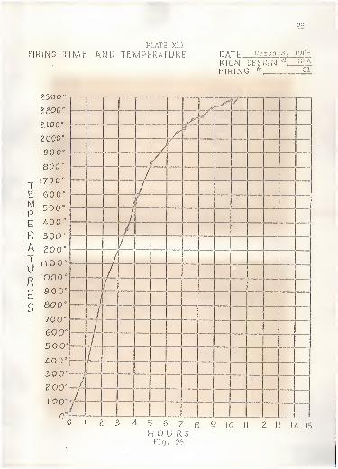
Time and Temperature . All firings were subjected from
two to six hours of preheating to insure dryness of pottery and
kiln. This was accomplished by having one burner burning as low
as the flame would allow. Time and temperature records were kept
on a graph in number of hours after firing was actually started;
for example, 7:30 A. M. to 8:30 A. M. was equal to hour one
(Plate XII, Fig. 26).
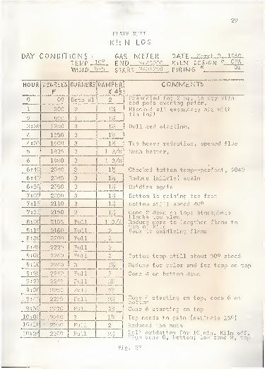
Kiln Log . Specific mechanical information in addition to
time and temperature was recorded on a Kiln Log (Plate XIII,
Fig. 27). This chart provided identified space for the date, the
kiln design, the firing number, the gas meter reading at the
start and finish of a firing, the hour, burner valve position,
damper position, atmospheric conditions of the day, and a place
for additional relevant comments. A copy of the specific record-
ings of a firing is found on Plate XII, Fig. 26, and Plate XIII,
Fig. 27. A normal firing was accomplished in ten to twelve hours
consuming between ten and fourteen thousand cubic feet of natural
gas.
A pyrometer was used to indicate changes that occurred
when experimenting for the correct quanity of fuel, or for detect-
ing an inaccurate supply of primary or secondary air. These
readings were noted on the Kiln Log under the "Comments'' column.
The pyrometer proved to be a vital tool to observe almost immed-
iately the results of a change in the fuel and oxygen ratio.
28
FIRING TIMEPLATE XII
AND TEMPERATURE DATF March 1968
KILN DESIGNFIRING *
4 CBA31
TEMPERATUR
E
S
2300°
t?„00°
Z\00e
Z000°
900°
800*
70 0°
600"
500'
4-00'
300°
200°
10 0'
000 s
9 0'
60 0°
70 °
600'
500'
A00°
300°
ZOO"
I 0'
_
—
. /'
//1
f—~•—
/ ., ......
//
/
/ . _ .
/
/.
/
/
"
Ll —
_
—«r
/
/
/
—...
<
U—
"
i
1 i
it 5 6 7H O U R 5Fig. 26
8 9 (O II IZ 13 14. 15
29
PLATE XI T
I
KILN LOG
DAY CONDITIONS : GAS. METER DATE" March 3, LQ<EMP -
10 ° FND 7443000 KILN DESIGN *, CBAr 7/i 'vi o^n Piouir. ^ 31WlWD 1 '-5 S'U
HOUR DEGREE'S
FBURNERS DAMPER
00 Both #1 2
1 300 2 llA
2 900 9 \V,
3 : 3C 13130 3 1%
4 1550 3 V/a
4 : 05 1600 3 V6
5 1835 3 1 3/8
6 1980 3 1 3/8
6 :4C 2040 3 V4
6 :45 2045 l]
4
6 :5C 2050 3 v/2
7 :05 2030 3 V6
7 :15 2110 3 1%
7 5 35 2150 3 V4
8 :00 21! Full l 3/4
8 (10 60 Full 2
8 :30 2200 Full . 2
8 4
5
2220 Full 2
00 2240 Full 2
9 10 2240 3 1^
9 25 2240 Full p
9 27 2245 Full ol/
9: 30 2250 Full •
9
:
45 2255 Full ^.1 1
<V4
9: 50 2270 Full
10: OC 22 3 \%10' 1C • 2250 Full 2
10: 2/ 2300 Full
COMMENTS
Preheated for 2 hr. to dry kilnand pots evening prior.Flockc.'; all secondary air withtin foil
Dull red starting.
Too heavy reduction, opened flue
uch better.
Checked bottom temp— perfect, 2040
Reduce (mildly) again
Oxidize again
Bottom is gaining too fast
Bottom still ahead 40°
Cone 2 down on too; atmosph-blocks top viewReduce more to lengthen flame totop of kiln
ck to oxidizing flame
ittom temp still about 50° ahead
Reduce for color and for temp on top
Cone 4 on bottom do i
Cone 4 starting on too, cono 6 obottomCone 6 starting on top
Top needs to gain (estimate 15°)
Reduced too muchFull oxidation for 10 min. Kiln off.! Ii g h cone 8 , b ot t om ; 1 ow cone 8 , top
Fig. 01
30
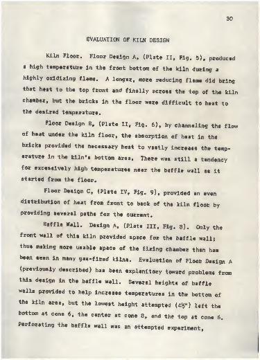
EVALUATION OF KILN DESIGN
Kiln Floor. Floor Design A, (Plate II, Fig. 5), produced
a high temperature in the front bottom of the kiln during a
highly oxidizing flame. A longer, more reducing flame did bring
that heat to the top front and finally across the top of the kiln
chamber, but the bricks in the floor were difficult to heat to
the desired temperature.
Floor Design B, (Plate II, Fig. 6), by channeling the flow
of heat under the kiln floor, the absorption of heat in the
bricks provided the necessary heat to vastly increase the temp-
erature in the kiln's bottom area. There was still a tendency
for excessively high temperatures near the baffle wall as it
started from the floor.
Floor Design C, (Plate IV, Fig. 9), provided an even
distribution of heat from front to back of the kiln floor by
providing several paths for the current.
Baffle Wall. Design A, (Plate III, Fig. 8). Only the
front wall of this kiln provided space for the baffle wall;
thus making more usable space of the firing chamber than has
been seen in many gas-fired kilns. Evaluation of Floor Design A
(previously described) has been explanitory toward problems fromthis design in the baffle wall. Several heights of baffle
walls provided to help increase temperatures in the bottom of
the kiln area, but the lowest height attempted (4fc") left the
bottom at cone 6, the center at cone 8, and the top at cone 6.
Perforating the baffle wall was an attempted experiment,
31
but was found to be too sensitive. A slight warpage of the
baffle wall during firings (due to the intense heat on one side
of the one and one-fourth inch thickness of the brick) reduced
the capacity of heat being directed to the top and directed that
heat to the kiln's sides. Also, the slightest misplacement of
baffle wall bricks vastly changed the exact path of the flames.
Baffle Wall design B (Plate IV, Fig. 9), was successful
in that it utilized radiation from the channeled heat found in
kiln floor designs B and C. The height and perforation of the
baffle wall was not highly critical. Differences in temperature
in each corner and the center of the kiln did not occur when the
height of the baffle was increased from nine inches to thirteen
and one-half inches. As the flames were directed upward abruptly
at the back bottom corner of the kiln, the current slowed to a
lazy, flowing flame. This slow flame was clearly visible during
mild to heavy reduction at red heat, and on to cone 8 temper-
atures as it laced toward the flue opening. Once this baffle
wall was in place, it did not have to be removed to load and
unload the kiln.
Ceiling Arch. No measureable difference was observed from
Design A to Design B in the ceiling arch. Correspondence withseveral other potters produced these comments in answer to my
findings about the direction of the curve and heighth of an arch
to close the ceiling of a kilni
From Professor Warren MacKenzie of the University of
Minnesota!
32
I would concurr Csicj completely with your obser-vation regarding a small kiln. However, in a largerkiln of 100 cubic feet or more, the smooth flow ofthe flue gases in whatever pattern is necessary forthe operation of the kiln is vital. In this respect,flat roofs are out, as well as very flat arches.However, the proportion of heighth to width of thekiln chamber is more important as well as whether itis natural or forced draft and what kind of fuel isused.I°
From Mr. Paul Soldner of the University of Iowa:
•••sounds right to me... *
From Mr. James Flaherty of the Archie Bray Foundation in
Helena, Montana:
I feel that the arch on a kiln should not betoo high as to trap the flame or too flat to breakup the flame... I think the arch leads the flame inthe kiln. If you're firing reduction, you want along, slow, flame. If the flame is trapped orbroken up in any way, this will have an effect onthe firing, reduction and glazes. 12
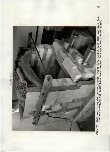
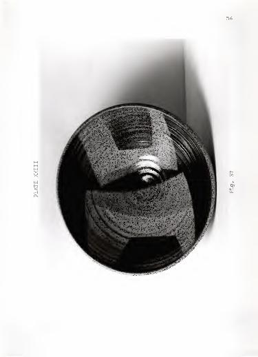
Evaluation Conclusions. Of the variations in design
construction, one combination of features proved to be superior.
It was referred to as Design CBA (Design C of the kiln floor,
Design B of the baffle wall, and Design A of the ceiling.) The
complete unit including these variations was photographed and
included on Plate XIV, Fig. 28.
Awareness of physical laws observed while experimenting
was the basis of establishing the purpose of this study. Several
l°Warren MacKenzie, letter to writer, 8 February 1968.
llPaul Soldner, letter to writer, 13 February 1968.
12James Flaherty, letter to writer, 12 February 1968.
34
occurrences are worthy of notice as they were important in
developing a controllable unit.
During several firings, the kiln reached temperatures of
2000° to 2100© F and then seemed to completely stall. After
considerable time (one to three hours) temperatures would climb
at a rate of normal advance. 13 Absorbtion of heat into the
bricks of the kiln may have permitted the temperature to finally
climb. After consulting with a gas company employee, it was
agreed to install a meter of a larger capacity. The change
proved to be fruitless. A mechanical engineer viewed the facil-
ity and concluded that the ratio of air and gas needed to be more
fully explored. It was suggested to close all secondary air
from the burner ports. Close observation of the Time and Temper-
ature Chart indicated that previous firings had included an
excessive amount of air that was (1) causing an improper oxygen
and fuel ratio and (2) was introducing unnecessary cold air into
the kiln chamber. After the amount of secondary air was reduced,
the "stall" no longer existed. With a faster firing time there
was less fuel consumed.
During initial firings, pottery in the bottom shelf of
the kiln was placed directly on kiln shelves that covered the
channeled kiln floor. Thus, these pieces were quickly exposed to
conduction of heat from the intensely hot burner channels in the
early stages of the firing. As a result of this direct conduction
of heat, the pottery on the bottom shelf reached maturing temp-
13Based on "Typical Heating Schedules", Clav and Glazesfor the Potter , by Daniel Rhodes, p. 201.
35
ature much too soon. Additional shelves placed three-fourths
inch above the shelves used to enclose the chamber eliminated the
direct conduction of heat to the pottery. The elevation was
accomplished with the use of pieces of a broken kiln shelf.
Only one bisque firing has been performed in this unit.
An oxydizing atmosphere was achieved for the firing by setting
the damper at two and one-half inches for the entire cycle,
secondary air was completely off and a regular burner adjustment
as used in a glaze firing was used. Cones were not used as the
color indicated a temperature of 1700—1800° F. This temperature
wes achieved in six hours with a two hour pre-heating time.
With only one burner on as low as would burn for the pre-heating
phase of the firing, alternations of positions were made from
one port to the other for uniformity within the kiln. Including
the bisque firing, a total of thirty-six firings were attempted
thus far.
Analysis of verbal comments from other potters recommend
a larger kiln for gas-fired operations. It is agreed that a
larger unit may perform the objective task of uniformity and
atmospheric conditions toward more perfection. The established
purpose of this study was to provide a modest size unit for a
potter on a limited time schedule for pottery.
36
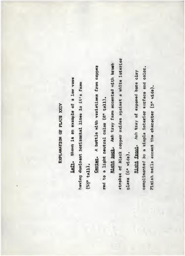
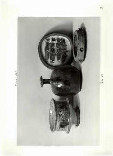
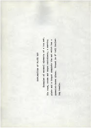
EVALUATION OF THESIS POTTERY
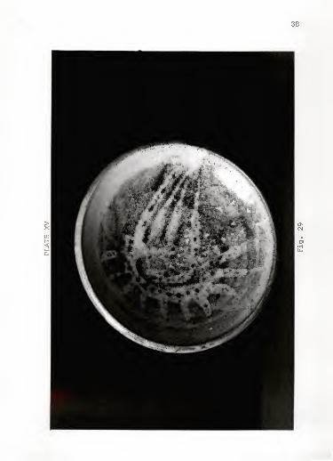
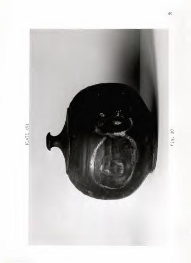
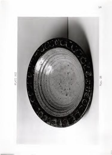
Twenty pieces of pottery were selected from the firings
during this study. An attempt has been made to include a
variety of sizes, designs and colors to present the goal of this
potter—a quality ware justifying the need for a quality kiln.
This study has an emphasis toward the facility of a kiln,
but it should be understood that the underlying ultimate efforts
are toward aesthetic endeavors. Total agreement is in accord
with Paul Soldneri "Control alone of a kiln is not enough. The
hardest thing is still getting beyond technical knowledge... "1*
All clay bodies of this pottery were of seventy-five per-
cent Pittsburg clay of Pittsburg, Kansas, and twenty-five percent
native earthenware clay from the Tuttle Creek Lake area near
Manhattan, Kansas. The glaze was a soda feldspar glaze with a
maturity range from cone 5 to cone 9.
l4Paul Soldner, letter to writer, 13 February 1968.
N(0 V)
-i
H
O >w +»c wo .rl
•h tn+» ©
H
>
Xra
©>o
©C ©* JCO (ff
O 3• J(0
•H ©. 3e •*H xo o
c» O•H M£ MH
•
nooo
73c
>-(0
<ff •
*o ©© "D
^ 3o s
•H Ox: -h5 o
uooo
£o
uto
u«EU©
ce
o -t
10
© cX >HH M-I
38
40
oCO
en•H
10
V)
co
o3
X C
o o
1
s
g
Cen o3
•H01
© •o-* cCO co
E+»
e 01
K •HO W«* •-<
iX
£ $w VH•H o-cH o>
e •«H c«-* enTJ •HC «co •x: •o
42
oo
en•H
•Di+»cioo1a>
«<0
MM EM N •
S O ^-»
«H l-l
«HW "O <0
H c +»< TO
-J ga, c iC
o ou. •H ••—.
'
o +»(0 <D
§ oM o cH « 10
< "D -C
j| II T>>_J •H •Ha, H «-I
X HUJ © r-l
E i-H
O flj
a> Eo 07
44
MH
H<a,
CMCO
en•H
>o•HH
to
H (0
C no (9
•H+» <DOB >
8•H
u to
X a> o>M •o VX
COC
w •H CFH -C c3 H
-DaO i
IU oO u> H
o U3 •H 3o O CO
M NH •H o< a
+»
1—4 rH «»-«
O, A oX 3OJ O to
"D w«
e c •
j= H «»*»
H <P CP
•H •o3 •HCT $
a> s-C O+» '—»
46
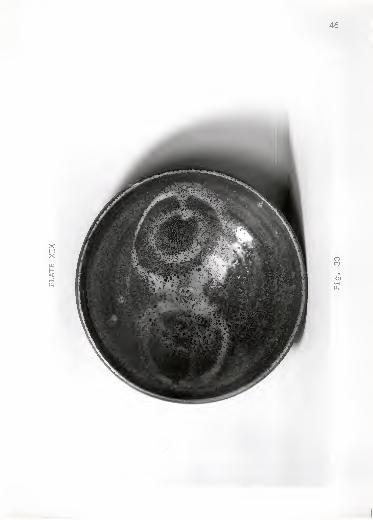
XHXw<.-J
COCO
en•H
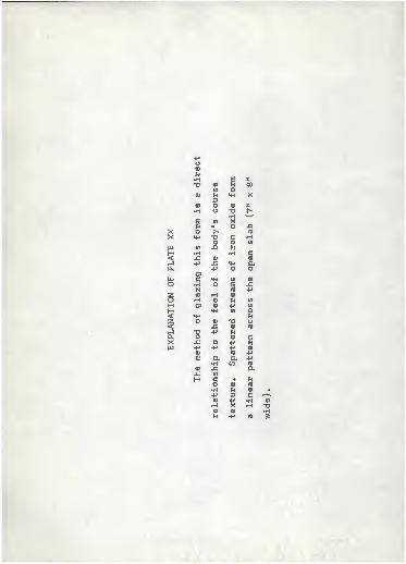
-RO0)
ft•H | X•o U
o00
ro
3«H X
VI O <D s•H o "0
•Hc-
g <n XB •> o JQ
so >* CD
«H *D c iHO o W
Ul -C uH •H •H c
3£ o+» -C «K a
a,0*C
+* o o
uu «* Ul
O •H o e .cN fl> 4*
S (V) i-H tt)H Q> n 07
M o» © +> 03
H «H 0) o< «M N2 O a) -o y3 x; o (0
i_I "O +» na. O a> cX Ja o H iUl +* +» +» a>
CO TO +»£ a a +»
•H coa -C ajB VI
H C • ho 0) 0)
•H i © •+» 3 c ^(D •H •H 0)
•H X -1 x»a> « •HM +> <o 3
48
50
CO
0>
c •w* um H4•a
5•H «X!
X9 +»• oh o-G E+» «en -oc c•H m+»u ••Ha 3••v
•Cn +» •C ««-*
•H a cen • oc • •H<v "O «-C c
«H •o E
•Hm c •©S o
•H •< H O
<* •HC•H X-DE •O ino *«^
52
HXXu:
CO
en
1 cC «HI• c+» If)
aa
(ft
X»
Xo
at
oa
>
c
NH4 Ho •a
ca
10
ou
•H OIV
o »o a •
(D *-*
• K H+» O •ro « -hH •«• * ea I <•
* > -H(/> O TJ
54
MMHa
cu
ro
Di•H
(0
•
> 1o
s «HoH •«B 4*
*i«MO c
•H•<-«
a •e c«8
X a• nc© +»
w §•H N
•H
§ 1o .cXt/> +»
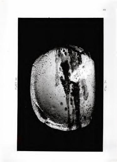
cI
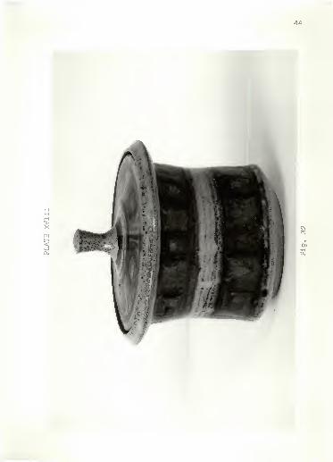
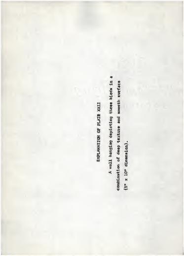
• c
! doml
ill).
oo
C(«IB
© ©
O Ha s>X w©
O -H
>, «© +>H C
9
JZW<
coH
©
aE
©
O©
o
Vx:
C
>- o-O ©
10
c
© in
•H H T> V)
3 -C © r-*
o +» •risvO fl ©
1
re
c•H -C
© •H wN a •Hro E C•-< o •Ho> o U.
56
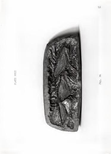
•+» i
• o> re Xftt c 3
•H w «-t
TO > re o<D H J2 c+> re £ •H
10 o •Hre •H •H
M-< -c re
p.o •
w5 4»
>£ «l H +» s>< +» re re CO
c c re
w © •H 01
H g re c •H
5re +* -C«H c H H
O. © o Oo 9 a
tu r-K +» re
O CO H re re
H re r-i H§
©> 3 IM © m o •
H (II o re
< XI N
5«« c +» re
o re o .HhJ a o>
g01 E re
« re re cU4
9-re +»
iEre
o reJ*
•re
X •» T3 • •HUl (A e JC •oa re re c
3 •H re
U re+»
Cre
XX re re &•H rH H CW a D) •H
58
H<
CO
01
59
ACKNOWLEDGEMENTS
The author expresses appreciation to his major professor,
Mr. Angelo C. Garzio, Professor of Art, Kansas State University,
for encouragement, helpful suggestions and guidance in preparing
this thesis; Mr. Oscar Larmer, Head of the Art Department at
Kansas State University, and Mr. Elmer Tomasch, Associate
Professor of Art at Kansas State University, for consultation.
Acknowledgement is also extended to Mr. Henry Serenco,
Mr. Douglas Noller, and Mr. Paul Lundquist for their assistance
in the form of advice, encouragement and physical help. To
Dr. Preston McNall, Department Head of Mechanical Engineering at
Kansas State University for his evaluation and advice. Mr. Tom
Nickols of the Manhattan Gas Company willingly offered much
needed information. Mr, Jerry McNichol contributed technical
photographic advice, Mr. Harry Livermore offered grammatical
evaluation and Mr. Lawrence Blaker took a personal interest while
photographing the pottery.
Professor Warren MacKenzie, University of Minnesota, Mr.
Paul Soldner, University of Iowa, Mr. James Flaherty of the
Archie Bray Foundation in Helena, Montana, and Mr. Frank
Kulasiewicz, New Mexico State University, gave valuable advice
by correspondence.
My wife, Bonnie, deserves credit for her patience, will-
ingness and understanding. She was responsible for proofreading
and for all typing.
60
BIBLIOGRAPHY
A. BOOKS
Gxeaves -Walker, A. F. Clay Plant Construction and Operation .
Brick and Clay Record, Chicago, 111., 1919.
Leach, Bernard. A Potter's Book . New York* TransAtlantic Arts,Inc., 1951,
A Potter's Work . London t Evelyn, Adams and Mackay,Ltd., 1967.
Nelson, Glenn. Ceramics . New York* Holt. Rinehart and Winston,1960.
Rhodes, Daniel. Clay jyjd Glazes for the Potter . Philadelphia!Chilton Co., 1957.
. Stoneware and Porcelain: The Art of Hj-gh-Ffoed Pottery.Philadelphia fChilton Co., 1959.
Sanders, Herbert. World of Japanese Ceramics . Tokyo i KodanshaInternational Ltd., 1967.
Singer, Felix and Sonj a S. Indus,toftf! Ceramics. New YorkiChemical Publishing Co., Inc., 19637^
Soldner, Paul. Kiln Construction . New York: American Crafts-man's Council, 1965.
B. PERIODICALS
Clark, Roland J. "Firing Ceramic Kilns," The Bulletin of theAmerican Ceramic Society , pp. 21-23; January, 19357
Johnson, B. M. "Super-Refractories for Small Kilns," The Bul-
lpVf\ Pf illfi American Ceramic Society, pp. 116-117;March,
Paxmalee, C. H. and Mrs. D. P. Randall. "Syracuse UniversityCexam
iS f&i '!'.^ ?uUfUn Si %h± American Ceramic Society ,
pp. 117-120| March, 1936.
Reimer, John J., and T. W. Drummond. "A Simple High-TemperatureGas B}"" ®**" JhS BuUel;^ o£ ihe American Ceramic Society ,
p. 477; December, 1937.
Rice, W. R. "Review of Data on Combustion in Kilns," Thft Bulletin2l ihS. American Ceramic Society , pp. 325-330? October, 1936.
61
Richardson, W. D. "Should the Down-draft Periodic Kiln be Roundox Rectangular," The Bulletin ofSociety , pp. 197-200; May, 1938.
Soldner, Paul. "Workshop* A Kiln is Built," Crafts Horizons ,
pp. 38-39, January/rebruary, 1965.
Suffron, F. 0. "Effects of Combustion Methods on TemperatureUniformity of Kilns and Furnaces," The Bulletin of theAmerican Ceramic Society , pp. 197-202; June, 1935.
C. PHAMPHLETS
* I Instgiat The Babcock""&~Wllcox
Babcock and Wilcox. B & W Insulating Firebrick . Augusta, Geor-Co.
AN EXPERIMENTAL STUDY IN THE DESIGN OFA SMALL DOWN-DRAFT GAS FIRED KILN
by
MAURICE WINSTON BERGGREN
B. F. A., Bethany College, 1962
AN ABSTRACT OF A MASTER'S THESIS
submitted in partial fulfillment of the
requirements for the degree
MASTER OF ARTS
Department of Art
KANSAS STATE UNIVERSITYManhattan, Kansas
1968
ABSTRACT
The purpose of this study was an attempt to develop a
controllable, even fixing, small kiln, capable of stoneware
temperatures.
The contents Included references to other kiln designs,
both In the past and present time, personal correspondence with
other potters, advice from a mechanical engineering consultant,
and personal experiences gained during the study.
A five and four-tenths cubic foot down-draft natural gas
fired kiln was constructed using a combination of dry insulating
and fire bricks. Seven variations in design were developed and
employed for evaluation. Separate kiln logs and time and temper-
ature charts were used for each firing to record results from
variations in the kiln design. Stages of construction were
photographed or illustrated to portray a pictorial development of
the unit. Firing records from a typical firing were included to
show operational procedures.
A combination of features from several experimental kiln
designs fulfilled the established goals of the study. Specifi-
cally, this design channeled the path of the flame under the
floor of the kiln to the kiln's bottom back; upward at the back
wall, across the kiln top and downward to the flue opening.
Again the direction of the flow of heat was channeled under the
kiln floor toward the back of the kiln and finally through the
chimney. Kiln Floor Design C, Baffle Wall Design B, and Ceiling
Design A were used in combination to fulfill the above kiln
design.
Firing time fox this kiln to reach cone 8 (2305° F) t
ranged between ten and twelve hours. This factor was variable
in regard to the amount of reduction desired and the amount of
experimenting with fuel and oxygen in order to gain knowledge in
producing specific control of the kiln.