Embed Size (px)
Citation preview
SSP-HExtra Heavy Duty
Slurry Pumps10.2020 / Rev. 0
Pump • Fire Fighting Units • Booster Set
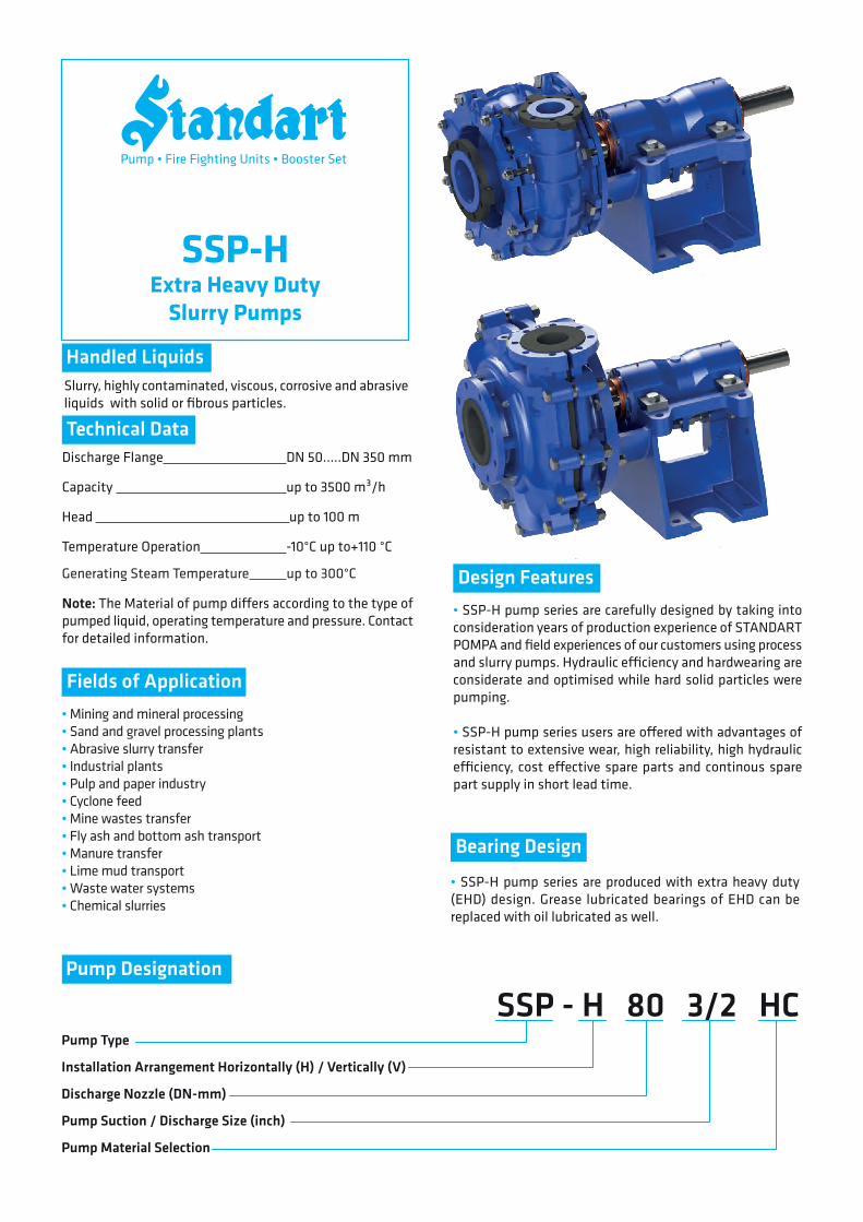
SSP-HExtra Heavy Duty
Slurry Pumps
Slurry, highly contaminated, viscous, corrosive and abrasive liquids with solid or fibrous particles.
Discharge Flange DN 50.....DN 350 mm
Capacity up to 3500 m³/h
Head up to 100 m
Temperature Operation -10°C up to+110 °C
Generating Steam Temperature up to 300°C
• SSP-H pump series are carefully designed by taking into consideration years of production experience of STANDART POMPA and field experiences of our customers using process and slurry pumps. Hydraulic e�ciency and hardwearing are considerate and optimised while hard solid particles were pumping.
• SSP-H pump series users are o�ered with advantages of resistant to extensive wear, high reliability, high hydraulic e�ciency, cost e�ective spare parts and continous spare part supply in short lead time.
• SSP-H pump series are produced with extra heavy duty (EHD) design. Grease lubricated bearings of EHD can be replaced with oil lubricated as well.
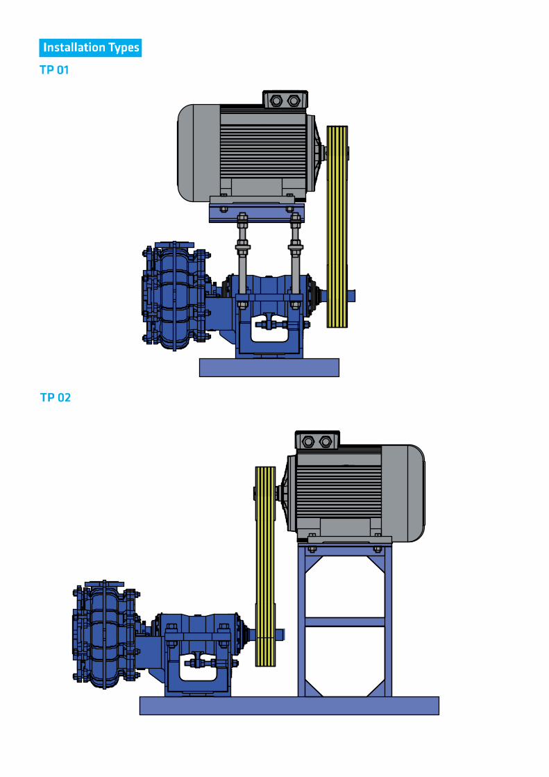
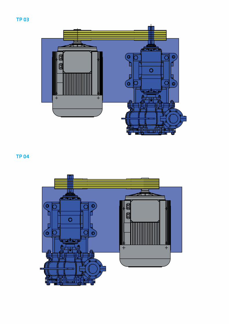
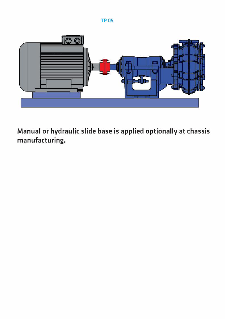
Pump Type
Installation Arrangement Horizontally (H) / Vertically (V)
Discharge Nozzle (DN-mm)
Pump Suction / Discharge Size (inch)
Pump Material Selection
SSP - H 80 3/2 HC
Handled Liquids
Technical Data
Design Features
Bearing Design
• Mining and mineral processing• Sand and gravel processing plants• Abrasive slurry transfer• Industrial plants• Pulp and paper industry• Cyclone feed• Mine wastes transfer• Fly ash and bottom ash transport• Manure transfer• Lime mud transport• Waste water systems• Chemical slurries
Fields of Application
Pump Designation
Note: The Material of pump di�ers according to the type of pumped liquid, operating temperature and pressure. Contact for detailed information.
Pump • Fire Fighting Units • Booster Set
20
10
20
30
40
50
60
70
80
90
100
40 60 80 100 200 300 400 500
Hm
(mss
)
Q(m /h)
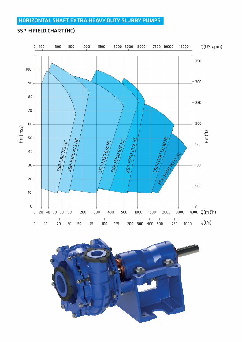
HORIZONTAL SHAFT EXTRA HEAVY DUTY SLURRY PUMPS
SSP-H FIELD CHART (HC)
1000 1500 2000 3
SSP-
H80
3/2
HC
SSP-
H10
0 4/
3 H
C
SSP-
H15
0 6/
4 H
CSS
P-H
200
8/6
HC
SSP-
H25
0 10
/8 H
C
SSP-
H30
0 12
/10
HC
3000 4000
SSP-
H350
14/1
2 HC
0
100 20 30 50 75 100 200125 300 500 1000750400 Q(l/s)
0 100 300 500 1000 1500 2000 3000 5000 7500 10000 15000 Q(US.gpm)
0
50
100
150
200
250
300
350
Hm
(ft)
0
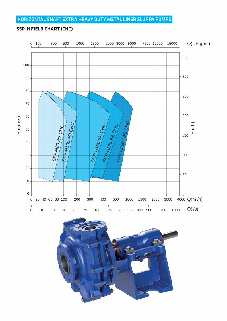
HORIZONTAL SHAFT EXTRA HEAVY DUTY METAL LINER SLURRY PUMPS
SSP-H FIELD CHART (CHC)
20
10
20
30
40
50
60
70
80
90
100
40 60 80 100 200 300 400 500
Hm
(mss
)
1000 1500 2000
SSP-
H80
3/2
CH
CSS
P-H
100
4/3
CH
C
SSP-
H15
0 6/
4 C
HC
SSP-
H20
0 8/
6 C
HC
SSP-
H25
0 10
/8 C
HC
3000 40000 Q(m /h)3
100 20 30 50 75 100 200125 300 500 1000750400 Q(l/s)
0 100 300 500 1000 1500 2000 3000 5000 7500 10000 15000 Q(US.gpm)
0
50
100
150
200
250
300
350
Hm
(ft)
0
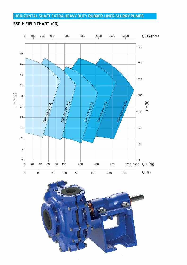
HORIZONTAL SHAFT EXTRA HEAVY DUTY RUBBER LINER SLURRY PUMPS
SSP-H FIELD CHART (CR)
Hm
(mss
)
20
5
10
15
20
25
30
35
40
45
40 60 80 100 200 400 800 1200 1600
50
SSP-
H80
3/2
CR
SSP-
H10
0 4/
3 CR
SSP-
H15
0 6/
4 CR
SSP-
H20
0 8/
6 CR
SSP-
H25
0 10
/8 C
R
0
0
Q(m /h)3
0 Q(l/s)
0
10 20 30 50 100 200 300
0 100 300 500200 1000 2000 50003500 Q(US.gpm)
25
50
75
100
125
150
175
Hm
(ft)
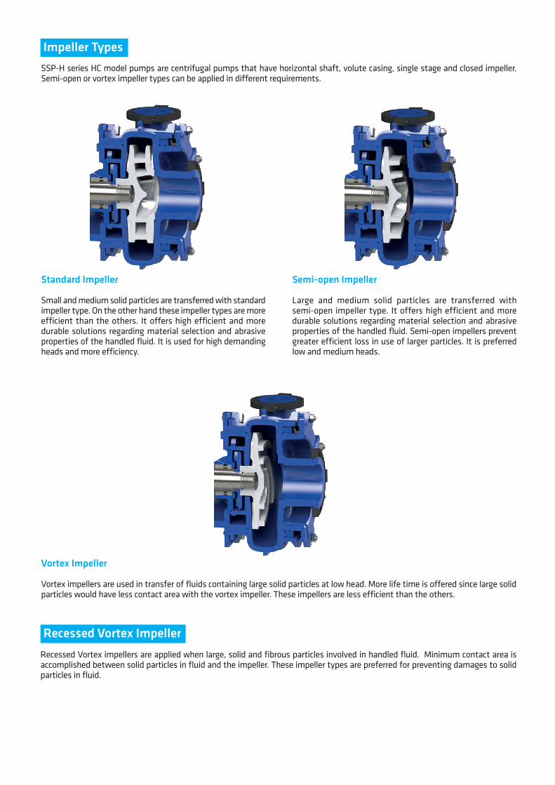
Impeller Types
Standard Impeller
Small and medium solid particles are transferred with standard impeller type. On the other hand these impeller types are more efficient than the others. It offers high efficient and more durable solutions regarding material selection and abrasive properties of the handled fluid. It is used for high demanding heads and more efficiency.
SSP-H series HC model pumps are centrifugal pumps that have horizontal shaft, volute casing, single stage and closed impeller. Semi-open or vortex impeller types can be applied in different requirements.
Semi-open Impeller
Large and medium solid particles are transferred with semi-open impeller type. It offers high efficient and more durable solutions regarding material selection and abrasive properties of the handled fluid. Semi-open impellers prevent greater efficient loss in use of larger particles. It is preferred low and medium heads.
Vortex Impeller
Vortex impellers are used in transfer of fluids containing large solid particles at low head. More life time is offered since large solid particles would have less contact area with the vortex impeller. These impellers are less efficient than the others.
Recessed Vortex ImpellerRecessed Vortex impellers are applied when large, solid and fibrous particles involved in handled fluid. Minimum contact area is accomplished between solid particles in fluid and the impeller. These impeller types are preferred for preventing damages to solid particles in fluid.
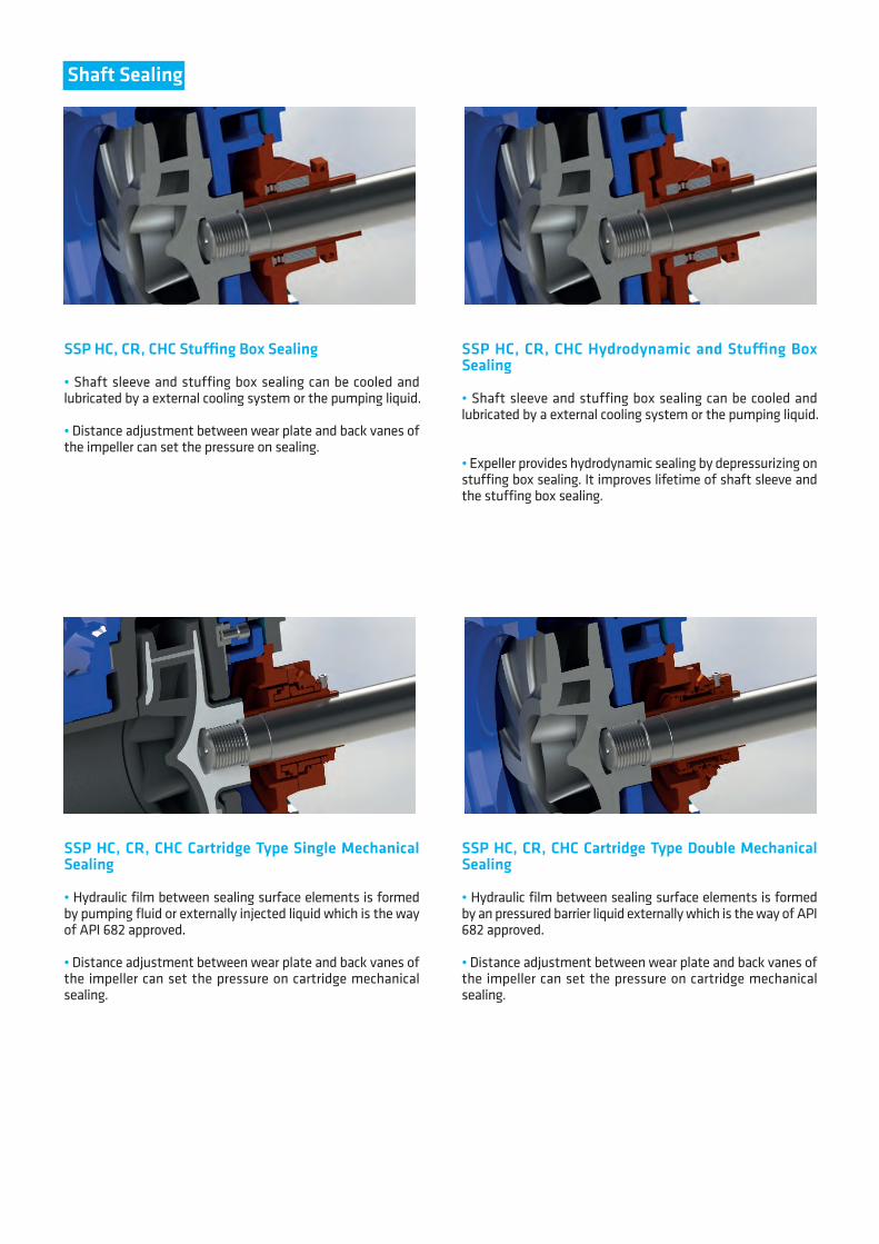
Shaft Sealing
SSP HC, CR, CHC Stu�ng Box Sealing
• Shaft sleeve and stuffing box sealing can be cooled and lubricated by a external cooling system or the pumping liquid.
• Distance adjustment between wear plate and back vanes of the impeller can set the pressure on sealing.
SSP HC, CR, CHC Hydrodynamic and Stu�ng Box Sealing
• Shaft sleeve and stuffing box sealing can be cooled and lubricated by a external cooling system or the pumping liquid.
• Expeller provides hydrodynamic sealing by depressurizing on stuffing box sealing. It improves lifetime of shaft sleeve and the stuffing box sealing.
SSP HC, CR, CHC Cartridge Type Single Mechanical Sealing
• Hydraulic film between sealing surface elements is formed by pumping fluid or externally injected liquid which is the way of API 682 approved.
• Distance adjustment between wear plate and back vanes of the impeller can set the pressure on cartridge mechanical sealing.
SSP HC, CR, CHC Cartridge Type Double Mechanical Sealing
• Hydraulic film between sealing surface elements is formed by an pressured barrier liquid externally which is the way of API 682 approved.
• Distance adjustment between wear plate and back vanes of the impeller can set the pressure on cartridge mechanical sealing.
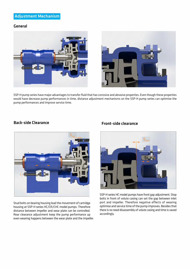
Adjustment Mechanism
SSP-H pump series have major advantages to transfer fluid that has corrosive and abrasive properties. Even though these properties would have decrease pump performances in time, distance adjustment mechanisms on the SSP-H pump series can optimise the pump performances and improve service time.
General
Back-side Clearance Front-side clearance
Stud bolts on bearing housing lead the movement of cartridge housing at SSP-H series HC/CR/CHC model pumps. Therefore distance between impeller and wear plate can be controlled. Rear clearance adjustment keep the pump performance up even wearing happens between the wear plate and the impeller.
SSP-H series HC model pumps have front gap adjustment. Stop bolts in front of volute casing can set the gap between inlet port and impeller. Therefore negative effects of wearing optimise and service time of the pump improves. Besides that there is no need disassembly of volute casing and time is saved accordingly.
Sfront
Srear
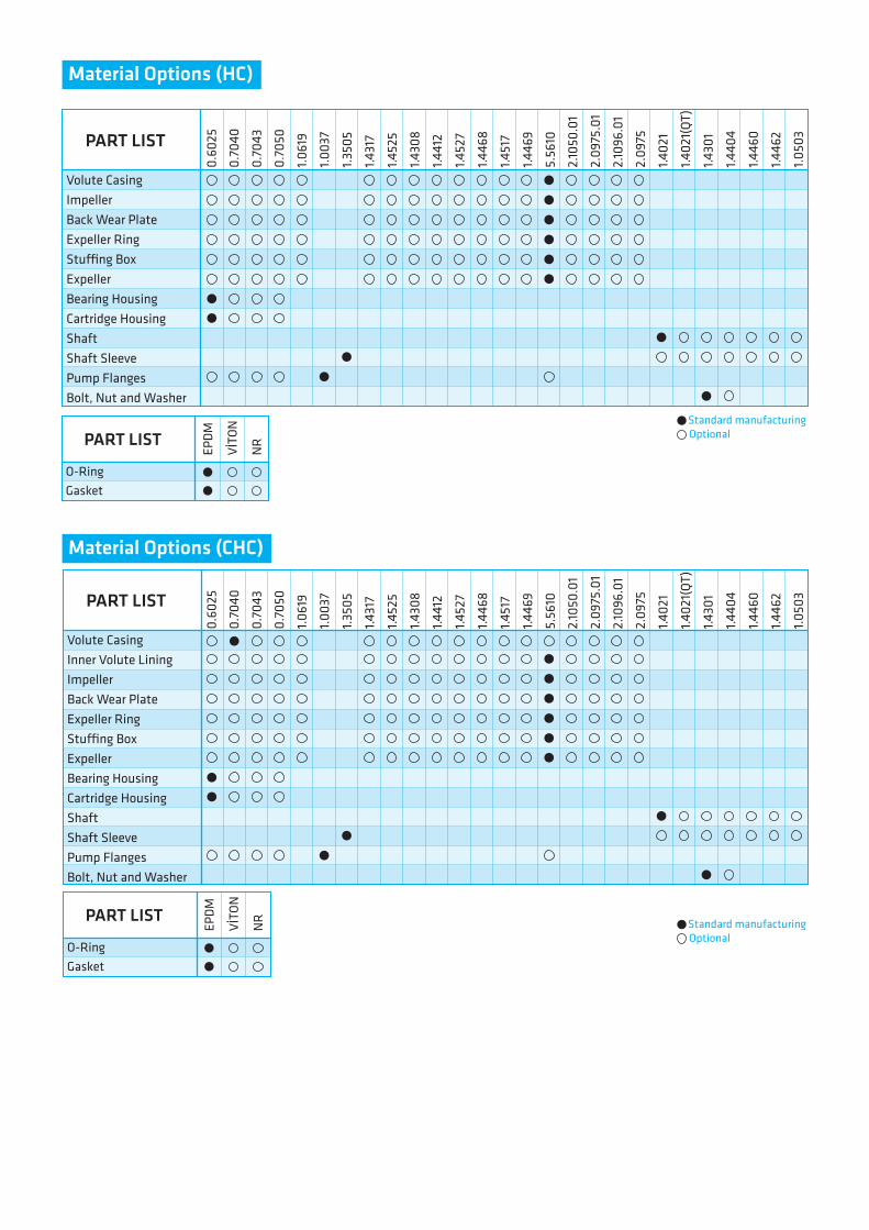
PART LIST
Volute CasingImpellerBack Wear PlateExpeller RingStu�ng BoxExpellerBearing HousingCartridge HousingShaftShaft SleevePump FlangesBolt, Nut and Washer
Material Options (HC)
Material Options (CHC)
PART LIST
O-RingGasket
EPDM
VİTO
N
NR
PART LIST
Volute CasingInner Volute LiningImpellerBack Wear PlateExpeller RingStu�ng BoxExpellerBearing HousingCartridge HousingShaftShaft SleevePump FlangesBolt, Nut and Washer
Standard manufacturingOptional
Standard manufacturingOptional
PART LIST
O-RingGasket
EPDM
VİTO
N
NR
0.60
25
0.70
40
0.70
43
0.70
50
1.061
9
1.003
7
1.350
5
1.431
7
1.452
5
1.430
8
1.441
2
1.452
7
1.446
8
1.451
7
1.446
9
5.56
10
2.10
50.0
1
2.09
75.0
1
2.10
96.0
1
2.09
75
1.402
1
1.402
1(QT
)
1.430
1
1.440
4
1.446
0
1.446
2
1.050
3
0.60
25
0.70
40
0.70
43
0.70
50
1.061
9
1.003
7
1.350
5
1.431
7
1.452
5
1.430
8
1.441
2
1.452
7
1.446
8
1.451
7
1.446
9
5.56
10
2.10
50.0
1
2.09
75.0
1
2.10
96.0
1
2.09
75
1.402
1
1.402
1(QT
)
1.430
1
1.440
4
1.446
0
1.446
2
1.050
3
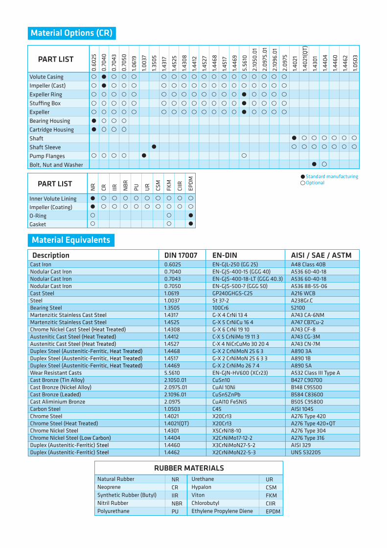
PART LIST
Volute CasingImpeller (Cast)Expeller RingStu�ng BoxExpellerBearing HousingCartridge HousingShaftShaft SleevePump FlangesBolt, Nut and Washer
PART LIST
RUBBER MATERIALS
Inner Volute LiningImpeller (Coating)O-RingGasket
Natural RubberNeopreneSynthetic Rubber (Butyl)Nitril RubberPolyurethane
NRCRIIRNBRPU
NR
CR IIR NBR
PU UR
CSM
FKM
CIIR
EPDM
Material Options (CR)
Standard manufacturingOptional
0.6025 0.7040 0.7043 0.7050 1.0619 1.0037 1.3505 1.4317 1.4525 1.4308 1.4412 1.4527 1.4468 1.4517 1.4469 5.5610 2.1050.01 2.0975.01 2.1096.01 2.0975 1.0503 1.4021 1.4021(QT) 1.4301 1.4404 1.4460 1.4462
EN-GJL-250 (GG 25) EN-GJS-400-15 (GGG 40) EN-GJS-400-18-LT (GGG 40.3) EN-GJS-500-7 (GGG 50) GP240GHGS-C25 St 37-2 100Cr6 G-X 4 CrNi 13 4 G-X 5 CrNiCu 16 4 G-X 6 CrNi 19 10 C-X 5 CrNiMo 19 11 3 C-X 4 NiCrCuMo 30 20 4 G-X 2 CrNiMoN 25 6 3 G-X 2 CrNiMoN 25 6 3 3 G-X 2 CrNiMo 26 7 4 EN-GJN-HV600 (XCr23) CuSn10 CuAl 10Ni CuSn5ZnPb CuAl10 Fe5Ni5 C45 X20Cr13 X20Cr13 X5CrNi18-10 X2CrNiMo17-12-2 X3CrNiMoN27-5-2 X2CrNiMoN22-5-3
A48 Class 40BA536 60-40-18A536 60-40-18A536 88-55-06A216 WCBA238Gr.C52100A743 CA-6NMA747 CB7Cu-2A743 CF-8A743 CG-3MA743 CN-7MA890 3AA890 1BA890 5AA532 Class III Type AB427 C90700B148 C95500B584 C83600B505 C95800AISI 1045 A276 Type 420 A276 Type 420+QT A276 Type 304A276 Type 316AISI 329UNS S32205
Description DIN 17007 EN-DIN AISI / SAE / ASTMCast Iron Nodular Cast IronNodular Cast IronNodular Cast IronCast Steel Steel Bearing Steel Martenzitic Stainless Cast Steel Martenzitic Stainless Cast SteelChrome Nickel Cast Steel (Heat Treated) Austenitic Cast Steel (Heat Treated)Austenitic Cast Steel (Heat Treated)Duplex Steel (Austenitic-Ferritic, Heat Treated) Duplex Steel (Austenitic-Ferritic, Heat Treated)Duplex Steel (Austenitic-Ferritic, Heat Treated)Wear Resistant Casts Cast Bronze (Tin Alloy) Cast Bronze (Nickel Alloy) Cast Bronze (Leaded) Cast Aliminium BronzeCarbon Steel Chrome Steel Chrome Steel (Heat Treated) Chrome Nickel Steel Chrome Nickel Steel (Low Carbon) Duplex (Austenitic-Ferritic) SteelDuplex (Austenitic-Ferritic) Steel
Material Equivalents
UrethaneHypalon VitonChlorobutylEthylene Propylene Diene
URCSMFKMCIIREPDM
0.60
25
0.70
40
0.70
43
0.70
50
1.061
9
1.003
7
1.350
5
1.431
7
1.452
5
1.430
8
1.441
2
1.452
7
1.446
8
1.451
7
1.446
9
5.56
10
2.10
50.0
1
2.09
75.0
1
2.10
96.0
1
2.09
75
1.402
1
1.402
1(QT
)
1.430
1
1.440
4
1.446
0
1.446
2
1.050
3