Embed Size (px)
Citation preview
Journal of Colloid and Interface Science 437 (2015) 181–186
Contents lists available at ScienceDirect
Journal of Colloid and Interface Science
www.elsevier .com/locate / jc is
Fabrication of 3D structured ZnO nanorod/reduced graphene oxidehydrogels and their use for photo-enhanced organic dye removal
http://dx.doi.org/10.1016/j.jcis.2014.08.0710021-9797/� 2014 Elsevier Inc. All rights reserved.
⇑ Corresponding author.E-mail address: [email protected] (S.H. Hur).
Van Hoang Luan, Huynh Ngoc Tien, Seung Hyun Hur ⇑School of Chemical Engineering, University of Ulsan, Daehak-ro 93, Nam-gu, Ulsan 680-749, South Korea
a r t i c l e i n f o
Article history:Received 11 June 2014Accepted 30 August 2014Available online 16 September 2014
Keywords:ZnO nanorodsReduced graphene oxide hydrogelMethylene blue
a b s t r a c t
Hybrid 3-dimensional (3D) structures composed of zinc oxide (ZnO) nanorods and reduced grapheneoxide hydrogel (rGOH) were fabricated by chemical reaction between Zn ions and GO followed by in-situlateral growth of ZnO nanorods using Zn ions as seed points. The 3D networked ZnO nanorod–rGOH(ZNR–rGOH) fabricated in this study exhibited excellent methylene blue (MB) removal efficiency dueto efficient physical adsorption of dye molecules because of electrostatic attractive forces and enhancedphotocatalytic activity by the laterally grown ZnO nanorods. The Langmuir–Hinshelwood rate constant ofZNR–rGOH was 4-fold higher than that of pristine rGO due to the enhanced photocatalytic effectsobtained by incorporating laterally grown ZnO nanorods inside the rGOH network.
� 2014 Elsevier Inc. All rights reserved.
1. Introduction with a conductive material such as graphene, which has a lower
Zinc oxide (ZnO) nanostructures are used in gas sensors, ultra-violet (UV) photodiodes, UV lasers, solar cells, and photocatalystsbecause of their high surface to volume ratio and their uniquephysical and optical properties such as a high excitation bindingenergy, a wide direct band gap, high piezoelectricity, and high pho-tocatalytic efficiency [1–7].
Graphene nanosheets, which contain a single layer of carbonatoms with a two-dimensional (2D) honeycomb structure, havebeen extensively studied in photocatalysis as supporting materialsfor metal oxide photocatalysts due to their excellent electronicconductivity, superior chemical stability, and high specific surfacearea [8–11]. Recent studies have shown that when one-dimen-sional (1D) ZnO nanorods are hybridized with other materials suchas graphene, metal nanoparticles, and semiconducting metal oxi-des, the electrical and electrochemical performances of sensorsor photocatalysts can be enhanced due to effective charge transferbetween ZnO and other materials [12]. Under UV illumination witha phonon energy higher energy than that of the band gap of ZnOnanorods, excitation of electrons from the valence band (VB) tothe conduction band (CB) leaves a positive hole in the VB andresults in electron–hole pairs, which can remove organic dyes suchas methylene blue (MB) by redox reaction. Generally, the photocat-alytic activity of pure ZnO is very low due to fast recombination ofelectron–hole pairs. However, when ZnO nanorods are in contact
work function than the conduction band of ZnO, effective chargetransfer from ZnO to graphene hinders the recombination of elec-tron–hole pairs, which results in enhanced degradation of MB [12].
Removal of dye-containing wastewater is challenging, becauseorganic dyes are resistant to simple UV and chemical treatments[13]. Hybrid structures composed of ZnO nanorods and chemicallycrosslinked three-dimensional (3D) graphene oxide (GO) may becandidates for effective removal of organic dye due to (i) effectiveadsorption afforded by a large surface area and strong interactionsbetween the GO and dye molecules, (ii) enhanced photocatalyticactivity resulting from effective charge transfer from ZnO nanorodsto 3D GO [14].
In this report, we fabricated hybrid structures composed of ZnOnanorods and 3D reduced GO hydrogel (rGOH) by a simple in-situhydrothermal process. Initially, a high surface area reduced GOhydrogel (rGOH) was fabricated by crosslinking Zn2+ ions and thefunctional groups of GO, then ZnO nanorods were grown in-situinside the 3D rGOH network by hydrothermal synthesis using Zn2+
ions as seeds for ZnO nanorods. GOH fabricated by Zn2+ ions in thisstudy had a highly developed 3D network structure. The MB removalefficiency of rGOH containing laterally grown ZnO nanorods wasmuch higher under both UV and visible light illumination than thatof the original GOH, which also contained a small amount of ZnOnanoparticles, because of the better crystal structures and enhancedlight absorption of the former hybrid structure. This type of multi-functional hybrid material can be effectively used in many applica-tions such as solar cells and reactive chemical adsorption undervisible light due to its enhanced electrical and optical properties[15–19].
182 V.H. Luan et al. / Journal of Colloid and Interface Science 437 (2015) 181–186
2. Experimental
2.1. Preparation of graphene oxide (GO)
GO was prepared from expanded graphite by the modifiedHummers’ method using sulfuric acid (H2SO4) and potassium per-manganate (KMnO4) [20]. All chemicals used in this study werepurchased from Sigma–Aldrich Korea. First, 500 mL of concen-trated H2SO4 was charged into a 3-L beaker under stirring with aTeflon impeller, and 5 g of expanded graphite was added slowlyunder stirring at 0 �C after thermal expansion by 1-min microwaveirradiation. Then, 30 g of KMnO4 was added slowly under vigorousstirring for 2 h at 35 �C to oxidize and exfoliate the expandedgraphite to graphene oxide. To finish the oxidation reaction, 6 Lof deionized water and 50 mL of hydrogen peroxide (H2O2,30 wt%) were added slowly. Vigorous bubbles were observed,accompanied by a color change from dark brown to yellow. Theslurry was washed four times with a 10% HCl solution to removemetal ions followed by washing with deionized water to com-pletely remove the acid until the pH of the GO suspension was6–7. The concentration of GO was adjusted to 5–10 mg mL�1 inaqueous solution for further experiments.
2.2. Preparation of rGOH
Twenty milliliters of GO solution (5 mg mL�1) was mixed with100 mg zinc acetate under stirring with a magnetic bar. Themixture was then ultrasonicated for 1 h at room temperature.Gelation of the mixture was completed by heating the mixture to90 �C and maintaining it at this temperature for 8 h. The resultingreduced graphene oxide hydrogel (rGOH) was freeze-dried at�37 �C for 2 days to remove moisture without destroying the 3Dstructure.
2.3. Preparation of ZNR–rGOH
Zinc solution was prepared by mixing 0.2 mol L�1 hexamethyl-ene tetramine (HMTA) and 0.2 mol L�1 zinc nitrate hexahydrate(Zn(NO3)2�6H2O) in deionized (DI) water, and this was then mixed
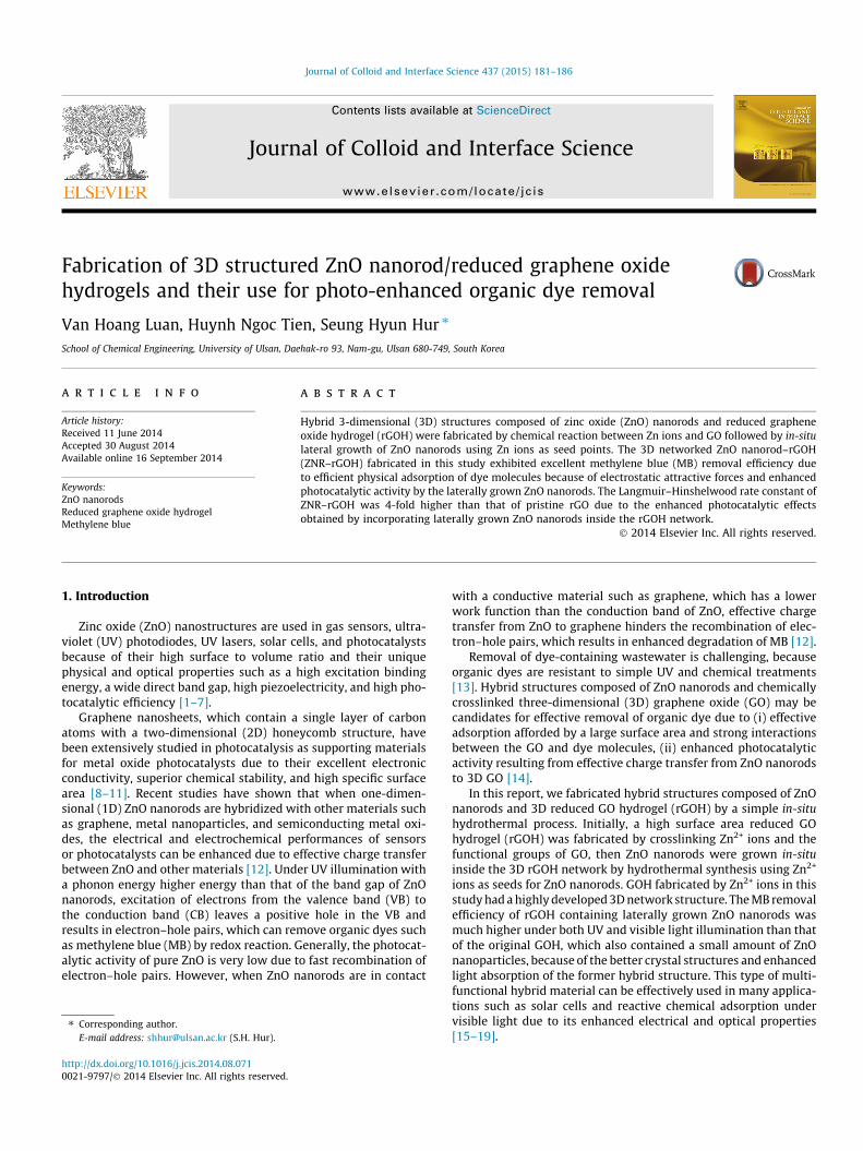
Fig. 1. (a) Schematics representation of rGOH fabrication steps. Photo images of (b) GO
with rGOH. The mixture was heated to 95 �C and maintained for4 h at this temperature to grow ZnO nanorods. The final productwas washed and filtered using copious amounts of DI water.
2.4. Characterization
The crystal structure of samples was characterized by X-ray dif-fraction (XRD, Rigaku, D/MAZX 2500V/PC, Japan) using a highpower X-ray diffractometer with Cu Ka radiation (35 kV, 20 mA,k = 1.5418 Å) at a scan rate of 2� (2h) per min. X-ray photoelectronspectra were obtained by X-ray photoelectron spectroscopy (XPS)(K-Alpha, Thermo Fisher Scientific ESCALAB 250Xi, USA) using anAl Ka X-ray source (1486.6 eV). Bulk structures of the compositeswere analyzed using cross-sectional images obtained by Fieldemission-scanning electron microscopy (FE-SEM, JOEL JSM-6500FE, Japan). Thermogravimetric analysis (TGA, TA Instrument,Q50, USA) was used to determine the thermal properties of varioushydrogels. Specific surface area was measured using a surface areaand porosity analyzer (Micromeritics, ASAP2020, USA) and calcu-lated using the Brunauer–Emmett–Teller (BET) equation.
2.5. Photocatalytic test
Twenty milligrams of the materials fabricated in this study,namely freeze-dried rGOH and ZNR–rGOH, were dispersed in200 ml of MB solution at a concentration of 25 mg L�1. The photo-catalytic test was performed in two steps. Firstly, MB was allowedto adsorb for 30 min under dark conditions. Then, the solution wasilluminated for 30 min under visible light (40 W and wavelengthrange >400 nm) or UV (20 W and wavelength 365 nm) and MBremoval was investigated. The amount of MB removed wasmeasured with a UV–vis spectrometer (UV–Vis, Analytik Jena,SPECORD 210, Germany).
3. Results and discussion
Fabrication of rGOH using zinc acetate is illustrated schemati-cally in Fig. 1. First, zinc acetate solution was added to the GO solu-tion and immediate mild gelation of GO was observed due to
, (c) mixture of GO and zinc acetate, and (d) rGOH after the crosslinking reaction.
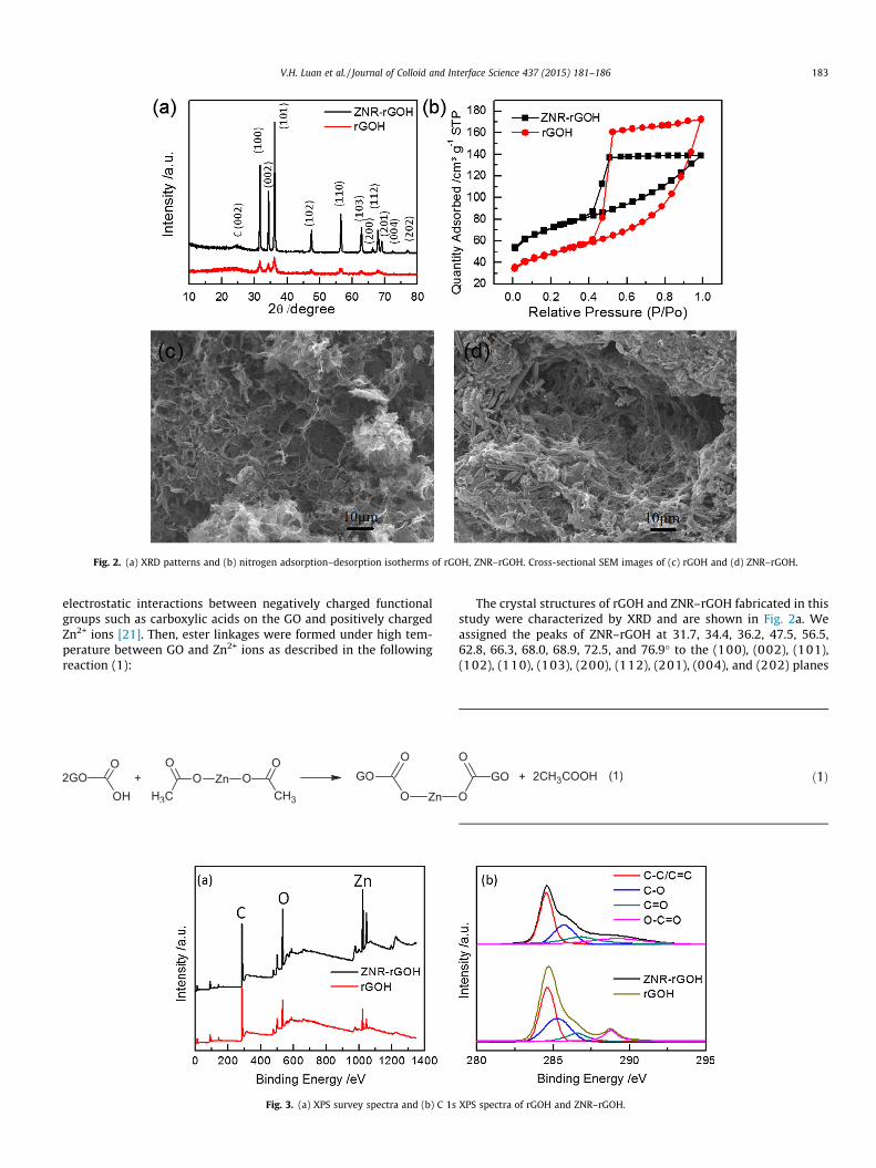
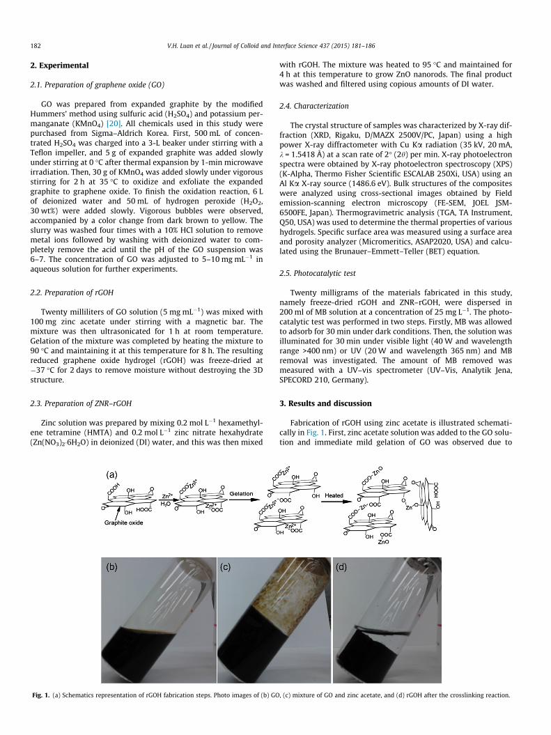
Fig. 2. (a) XRD patterns and (b) nitrogen adsorption–desorption isotherms of rGOH, ZNR–rGOH. Cross-sectional SEM images of (c) rGOH and (d) ZNR–rGOH.
V.H. Luan et al. / Journal of Colloid and Interface Science 437 (2015) 181–186 183
electrostatic interactions between negatively charged functionalgroups such as carboxylic acids on the GO and positively chargedZn2+ ions [21]. Then, ester linkages were formed under high tem-perature between GO and Zn2+ ions as described in the followingreaction (1):
Fig. 3. (a) XPS survey spectra and (b) C 1s
The crystal structures of rGOH and ZNR–rGOH fabricated in thisstudy were characterized by XRD and are shown in Fig. 2a. Weassigned the peaks of ZNR–rGOH at 31.7, 34.4, 36.2, 47.5, 56.5,62.8, 66.3, 68.0, 68.9, 72.5, and 76.9� to the (100), (002), (101),(102), (110), (103), (200), (112), (201), (004), and (202) planes
XPS spectra of rGOH and ZNR–rGOH.
ð1Þ
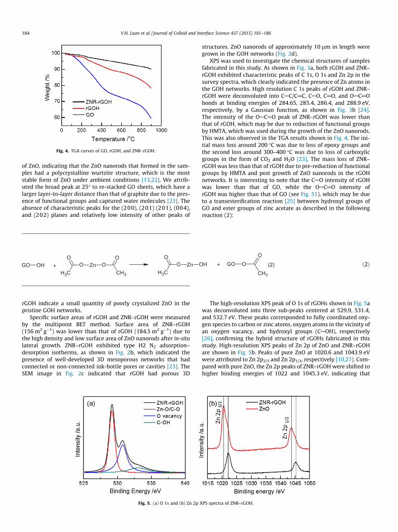
Fig. 4. TGA curves of GO, rGOH, and ZNR–rGOH.
184 V.H. Luan et al. / Journal of Colloid and Interface Science 437 (2015) 181–186
of ZnO, indicating that the ZnO nanorods that formed in the sam-ples had a polycrystalline wurtzite structure, which is the moststable form of ZnO under ambient conditions [13,22]. We attrib-uted the broad peak at 25� to re-stacked GO sheets, which have alarger layer-to-layer distance than that of graphite due to the pres-ence of functional groups and captured water molecules [23]. Theabsence of characteristic peaks for the (200), (201) (201), (004),and (202) planes and relatively low intensity of other peaks of
ð2Þ
rGOH indicate a small quantity of poorly crystalized ZnO in thepristine GOH networks.
Specific surface areas of rGOH and ZNR–rGOH were measuredby the multipoint BET method. Surface area of ZNR–rGOH(156 m2 g�1) was lower than that of rGOH (184.5 m2 g�1) due tothe high density and low surface area of ZnO nanorods after in-situlateral growth. ZNR–rGOH exhibited type H2 N2 adsorption–desorption isotherms, as shown in Fig. 2b, which indicated thepresence of well-developed 3D mesoporous networks that hadconnected or non-connected ink-bottle pores or cavities [23]. TheSEM image in Fig. 2c indicated that rGOH had porous 3D
Fig. 5. (a) O 1s and (b) Zn 2p X
structures. ZnO nanorods of approximately 10 lm in length weregrown in the GOH networks (Fig. 2d).
XPS was used to investigate the chemical structures of samplesfabricated in this study. As shown in Fig. 3a, both rGOH and ZNR–rGOH exhibited characteristic peaks of C 1s, O 1s and Zn 2p in thesurvey spectra, which clearly indicated the presence of Zn atoms inthe GOH networks. High resolution C 1s peaks of rGOH and ZNR–rGOH were deconvoluted into CAC/C@C, CAO, C@O, and OAC@Obonds at binding energies of 284.65, 285.4, 286.4, and 288.9 eV,respectively, by a Gaussian function, as shown in Fig. 3b [24].The intensity of the OAC@O peak of ZNR–rGOH was lower thanthat of rGOH, which may be due to reduction of functional groupsby HMTA, which was used during the growth of the ZnO nanorods.This was also observed in the TGA results shown in Fig. 4. The ini-tial mass loss around 200 �C was due to loss of epoxy groups andthe second loss around 300–400 �C was due to loss of carboxylicgroups in the form of CO2 and H2O [23]. The mass loss of ZNR–rGOH was less than that of rGOH due to pre-reduction of functionalgroups by HMTA and post growth of ZnO nanorods in the rGOHnetworks. It is interesting to note that the CAO intensity of rGOHwas lower than that of GO, while the OAC@O intensity ofrGOH was higher than that of GO (see Fig. S1), which may be dueto a transesterification reaction [25] between hydroxyl groups ofGO and ester groups of zinc acetate as described in the followingreaction (2):
The high-resolution XPS peak of O 1s of rGOHs shown in Fig. 5awas deconvoluted into three sub-peaks centered at 529.9, 531.4,and 532.7 eV. These peaks corresponded to fully coordinated oxy-gen species to carbon or zinc atoms, oxygen atoms in the vicinity ofan oxygen vacancy, and hydroxyl groups (CAOH), respectively[26], confirming the hybrid structure of rGOHs fabricated in thisstudy. High-resolution XPS peaks of Zn 2p of ZnO and ZNR–rGOHare shown in Fig. 5b. Peaks of pure ZnO at 1020.6 and 1043.9 eVwere attributed to Zn 2p2/3 and Zn 2p1/3, respectively [10,27]. Com-pared with pure ZnO, the Zn 2p peaks of ZNR–rGOH were shifted tohigher binding energies of 1022 and 1045.3 eV, indicating that
PS spectra of ZNR–rGOH.
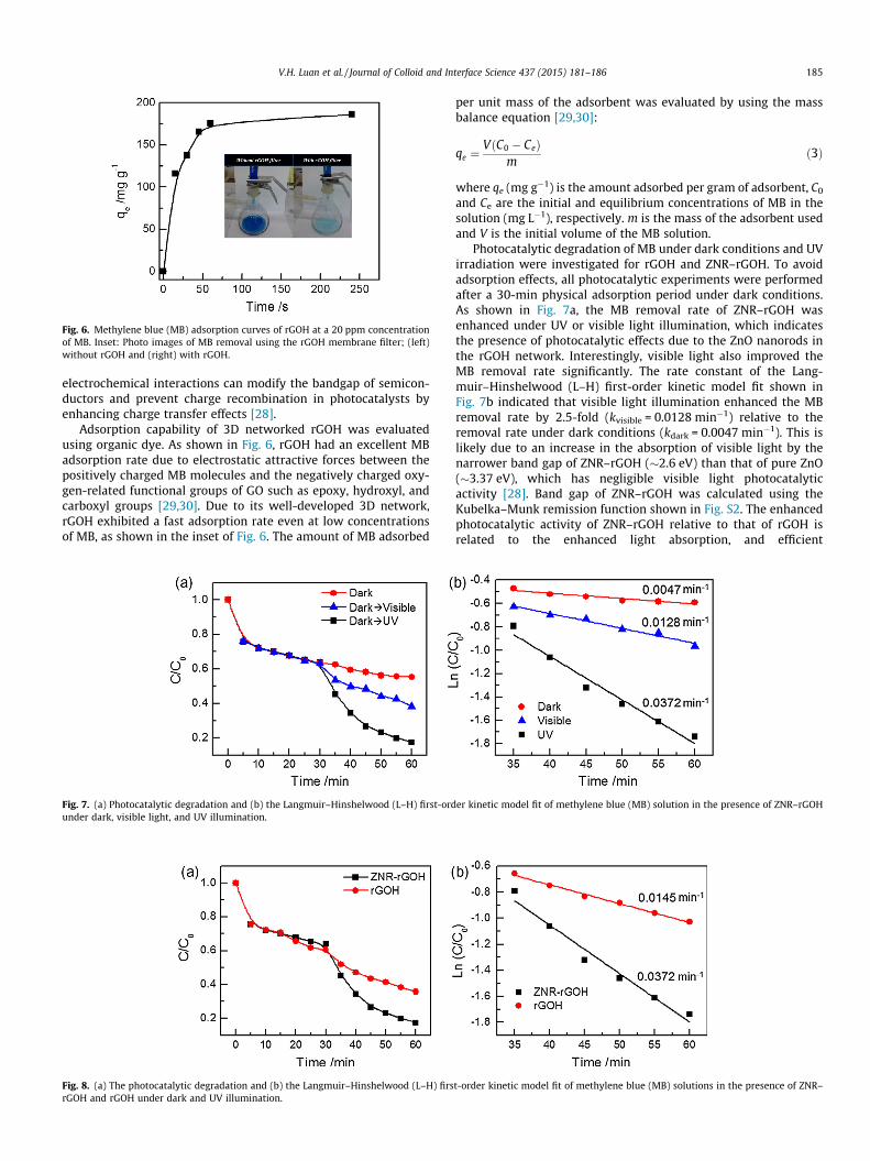
Fig. 6. Methylene blue (MB) adsorption curves of rGOH at a 20 ppm concentrationof MB. Inset: Photo images of MB removal using the rGOH membrane filter; (left)without rGOH and (right) with rGOH.
V.H. Luan et al. / Journal of Colloid and Interface Science 437 (2015) 181–186 185
electrochemical interactions can modify the bandgap of semicon-ductors and prevent charge recombination in photocatalysts byenhancing charge transfer effects [28].
Adsorption capability of 3D networked rGOH was evaluatedusing organic dye. As shown in Fig. 6, rGOH had an excellent MBadsorption rate due to electrostatic attractive forces between thepositively charged MB molecules and the negatively charged oxy-gen-related functional groups of GO such as epoxy, hydroxyl, andcarboxyl groups [29,30]. Due to its well-developed 3D network,rGOH exhibited a fast adsorption rate even at low concentrationsof MB, as shown in the inset of Fig. 6. The amount of MB adsorbed
Fig. 7. (a) Photocatalytic degradation and (b) the Langmuir–Hinshelwood (L–H) first-ordunder dark, visible light, and UV illumination.
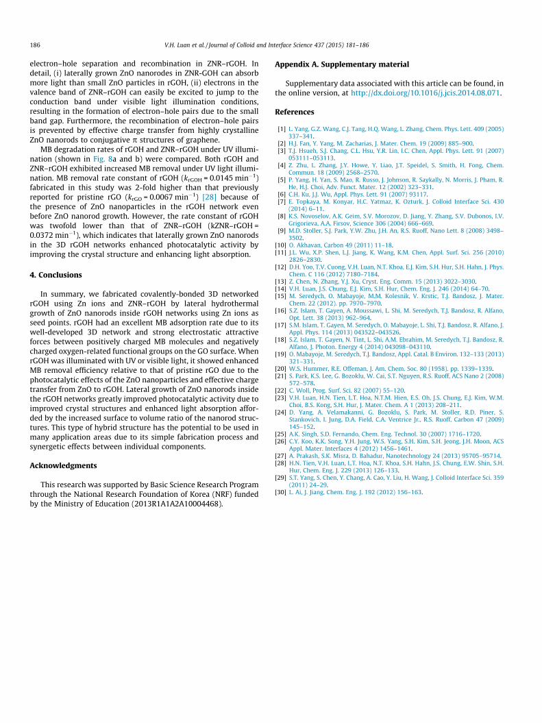
Fig. 8. (a) The photocatalytic degradation and (b) the Langmuir–Hinshelwood (L–H) firsrGOH and rGOH under dark and UV illumination.
per unit mass of the adsorbent was evaluated by using the massbalance equation [29,30]:
qe ¼VðC0 � CeÞ
mð3Þ
where qe (mg g�1) is the amount adsorbed per gram of adsorbent, C0
and Ce are the initial and equilibrium concentrations of MB in thesolution (mg L�1), respectively. m is the mass of the adsorbent usedand V is the initial volume of the MB solution.
Photocatalytic degradation of MB under dark conditions and UVirradiation were investigated for rGOH and ZNR–rGOH. To avoidadsorption effects, all photocatalytic experiments were performedafter a 30-min physical adsorption period under dark conditions.As shown in Fig. 7a, the MB removal rate of ZNR–rGOH wasenhanced under UV or visible light illumination, which indicatesthe presence of photocatalytic effects due to the ZnO nanorods inthe rGOH network. Interestingly, visible light also improved theMB removal rate significantly. The rate constant of the Lang-muir–Hinshelwood (L–H) first-order kinetic model fit shown inFig. 7b indicated that visible light illumination enhanced the MBremoval rate by 2.5-fold (kvisible = 0.0128 min�1) relative to theremoval rate under dark conditions (kdark = 0.0047 min�1). This islikely due to an increase in the absorption of visible light by thenarrower band gap of ZNR–rGOH (�2.6 eV) than that of pure ZnO(�3.37 eV), which has negligible visible light photocatalyticactivity [28]. Band gap of ZNR–rGOH was calculated using theKubelka–Munk remission function shown in Fig. S2. The enhancedphotocatalytic activity of ZNR–rGOH relative to that of rGOH isrelated to the enhanced light absorption, and efficient
er kinetic model fit of methylene blue (MB) solution in the presence of ZNR–rGOH
t-order kinetic model fit of methylene blue (MB) solutions in the presence of ZNR–
186 V.H. Luan et al. / Journal of Colloid and Interface Science 437 (2015) 181–186
electron–hole separation and recombination in ZNR–rGOH. Indetail, (i) laterally grown ZnO nanorodes in ZNR-GOH can absorbmore light than small ZnO particles in rGOH, (ii) electrons in thevalence band of ZNR–rGOH can easily be excited to jump to theconduction band under visible light illumination conditions,resulting in the formation of electron–hole pairs due to the smallband gap. Furthermore, the recombination of electron–hole pairsis prevented by effective charge transfer from highly crystallineZnO nanorods to conjugative p structures of graphene.
MB degradation rates of rGOH and ZNR–rGOH under UV illumi-nation (shown in Fig. 8a and b) were compared. Both rGOH andZNR–rGOH exhibited increased MB removal under UV light illumi-nation. MB removal rate constant of rGOH (krGOH = 0.0145 min�1)fabricated in this study was 2-fold higher than that previouslyreported for pristine rGO (krGO = 0.0067 min�1) [28] because ofthe presence of ZnO nanoparticles in the rGOH network evenbefore ZnO nanorod growth. However, the rate constant of rGOHwas twofold lower than that of ZNR–rGOH (kZNR–rGOH =0.0372 min�1), which indicates that laterally grown ZnO nanorodsin the 3D rGOH networks enhanced photocatalytic activity byimproving the crystal structure and enhancing light absorption.
4. Conclusions
In summary, we fabricated covalently-bonded 3D networkedrGOH using Zn ions and ZNR–rGOH by lateral hydrothermalgrowth of ZnO nanorods inside rGOH networks using Zn ions asseed points. rGOH had an excellent MB adsorption rate due to itswell-developed 3D network and strong electrostatic attractiveforces between positively charged MB molecules and negativelycharged oxygen-related functional groups on the GO surface. WhenrGOH was illuminated with UV or visible light, it showed enhancedMB removal efficiency relative to that of pristine rGO due to thephotocatalytic effects of the ZnO nanoparticles and effective chargetransfer from ZnO to rGOH. Lateral growth of ZnO nanorods insidethe rGOH networks greatly improved photocatalytic activity due toimproved crystal structures and enhanced light absorption affor-ded by the increased surface to volume ratio of the nanorod struc-tures. This type of hybrid structure has the potential to be used inmany application areas due to its simple fabrication process andsynergetic effects between individual components.
Acknowledgments
This research was supported by Basic Science Research Programthrough the National Research Foundation of Korea (NRF) fundedby the Ministry of Education (2013R1A1A2A10004468).
Appendix A. Supplementary material
Supplementary data associated with this article can be found, inthe online version, at http://dx.doi.org/10.1016/j.jcis.2014.08.071.
References
[1] L. Yang, G.Z. Wang, C.J. Tang, H.Q. Wang, L. Zhang, Chem. Phys. Lett. 409 (2005)337–341.
[2] H.J. Fan, Y. Yang, M. Zacharias, J. Mater. Chem. 19 (2009) 885–900.[3] T.J. Hsueh, S.J. Chang, C.L. Hsu, Y.R. Lin, I.C. Chen, Appl. Phys. Lett. 91 (2007)
053111–053113.[4] Z. Zhu, L. Zhang, J.Y. Howe, Y. Liao, J.T. Speidel, S. Smith, H. Fong, Chem.
Commun. 18 (2009) 2568–2570.[5] P. Yang, H. Yan, S. Mao, R. Russo, J. Johnson, R. Saykally, N. Morris, J. Pham, R.
He, H.J. Choi, Adv. Funct. Mater. 12 (2002) 323–331.[6] C.H. Ku, J.J. Wu, Appl. Phys. Lett. 91 (2007) 93117.[7] E. Topkaya, M. Konyar, H.C. Yatmaz, K. Ozturk, J. Colloid Interface Sci. 430
(2014) 6–11.[8] K.S. Novoselov, A.K. Geim, S.V. Morozov, D. Jiang, Y. Zhang, S.V. Dubonos, I.V.
Grigorieva, A.A. Firsov, Science 306 (2004) 666–669.[9] M.D. Stoller, S.J. Park, Y.W. Zhu, J.H. An, R.S. Ruoff, Nano Lett. 8 (2008) 3498–
3502.[10] O. Akhavan, Carbon 49 (2011) 11–18.[11] J.L. Wu, X.P. Shen, L.J. Jiang, K. Wang, K.M. Chen, Appl. Surf. Sci. 256 (2010)
2826–2830.[12] D.H. Yoo, T.V. Cuong, V.H. Luan, N.T. Khoa, E.J. Kim, S.H. Hur, S.H. Hahn, J. Phys.
Chem. C 116 (2012) 7180–7184.[13] Z. Chen, N. Zhang, Y.J. Xu, Cryst. Eng. Comm. 15 (2013) 3022–3030.[14] V.H. Luan, J.S. Chung, E.J. Kim, S.H. Hur, Chem. Eng. J. 246 (2014) 64–70.[15] M. Seredych, O. Mabayoje, M.M. Kolesnik, V. Krstic, T.J. Bandosz, J. Mater.
Chem. 22 (2012). pp. 7970–7970.[16] S.Z. Islam, T. Gayen, A. Moussawi, L. Shi, M. Seredych, T.J. Bandosz, R. Alfano,
Opt. Lett. 38 (2013) 962–964.[17] S.M. Islam, T. Gayen, M. Seredych, O. Mabayoje, L. Shi, T.J. Bandosz, R. Alfano, J.
Appl. Phys. 114 (2013) 043522–043526.[18] S.Z. Islam, T. Gayen, N. Tint, L. Shi, A.M. Ebrahim, M. Seredych, T.J. Bandosz, R.
Alfano, J. Photon. Energy 4 (2014) 043098–043110.[19] O. Mabayoje, M. Seredych, T.J. Bandosz, Appl. Catal. B Environ. 132–133 (2013)
321–331.[20] W.S. Hummer, R.E. Offeman, J. Am. Chem. Soc. 80 (1958). pp. 1339–1339.[21] S. Park, K.S. Lee, G. Bozoklu, W. Cai, S.T. Nguyen, R.S. Ruoff, ACS Nano 2 (2008)
572–578.[22] C. Woll, Prog. Surf. Sci. 82 (2007) 55–120.[23] V.H. Luan, H.N. Tien, L.T. Hoa, N.T.M. Hien, E.S. Oh, J.S. Chung, E.J. Kim, W.M.
Choi, B.S. Kong, S.H. Hur, J. Mater. Chem. A 1 (2013) 208–211.[24] D. Yang, A. Velamakanni, G. Bozoklu, S. Park, M. Stoller, R.D. Piner, S.
Stankovich, I. Jung, D.A. Field, C.A. Ventrice Jr., R.S. Ruoff, Carbon 47 (2009)145–152.
[25] A.K. Singh, S.D. Fernando, Chem. Eng. Technol. 30 (2007) 1716–1720.[26] C.Y. Koo, K.K. Song, Y.H. Jung, W.S. Yang, S.H. Kim, S.H. Jeong, J.H. Moon, ACS
Appl. Mater. Interfaces 4 (2012) 1456–1461.[27] A. Prakash, S.K. Misra, D. Bahadur, Nanotechnology 24 (2013) 95705–95714.[28] H.N. Tien, V.H. Luan, L.T. Hoa, N.T. Khoa, S.H. Hahn, J.S. Chung, E.W. Shin, S.H.
Hur, Chem. Eng. J. 229 (2013) 126–133.[29] S.T. Yang, S. Chen, Y. Chang, A. Cao, Y. Liu, H. Wang, J. Colloid Interface Sci. 359
(2011) 24–29.[30] L. Ai, J. Jiang, Chem. Eng. J. 192 (2012) 156–163.


