Embed Size (px)
Citation preview

1
sFmdttsttl
iSfemswtft�nh�diudrhtsmt
tfis
J
Downloa
Jianfeng XuCenter for Magnetic Recording Research,
University of California,San Diego 9500 Gilman Drive,
La Jolla, CA 92093e-mail: [email protected]
Izhak EtsionFellow ASME
Department of Mechanical Engineering,Technion,
Haifa 32000, Israele-mail: [email protected]
Frank E. TalkeFellow ASME
Center for Magnetic Recording Research,University of California,
San Diego 9500 Gilman Drive,Mail Code 0401, La Jolla, CA 92093
e-mail: [email protected]
Failure of Brittle and Ductile HardDisks Due to High Shock LevelsThe failure due to accidental drop of magnetic recording disks made of brittle or ductilematerials is of great interest in the design of small form factor hard disk drives. In thisstudy, fracture of glass disks (brittle material) and plastic deformation of aluminum disks(ductile material) at very high shock levels caused by accidental drop are investigatedusing finite element analysis. It is found that failure inception for both disk types occursat the inside perimeter of the disk. For glass disks, cracks are found to propagate towardthe outer perimeter of the disk along distinct radial lines associated with the largestbending moment of the disk. The critical shock level at which failure originates increaseswith an increase in the clamp diameter, a reduction in the disk diameter, and an increasein the thickness of the disk. Some experimental results are presented to validate thenumerical model. �DOI: 10.1115/1.4000238�
Keywords: shock, ductile, brittle, hard disk drive, magnetic recording
IntroductionDisk drives are presently used in many consumer applications
uch as hand held music players and personal digital assistants.urther application of disk drive technology in cars and otherobile devices are anticipated. Hard disks that are used in mobile
evices may experience very high shock levels, on the order ofhousands of Gs, if they are dropped accidentally. Many field re-urns of disk drives, such as those used in ipods, for example,how disk breakage caused by accidental dropping. To guaranteehe reliable performance of hard disk drives under those condi-ions, the characteristics and response of hard disks to high shockevels has become an important design consideration.
A number of studies have been undertaken in the past concern-ng the dynamic response of hard disk drives due to shock loads.chreck �1� studied the problem of shock on the head-disk inter-ace experimentally and used the magnetic read back signal tovaluate the damage. Allen and Bogy �2� carried out both experi-ental work and finite element analysis to determine the effect of
hock loads on hard disk substrates, suspensions, and sliders. Ed-ards �3� performed a finite element analysis of a hard disk drive
o study the transient response of the head-disk interface as aunction of nonoperational shock loads. Lee et al. �4� studied theransient response of a suspension subject to a shock impulse. Lin5� investigated the effects of drive enclosure stiffness, disk thick-ess, actuator stiffness, and bearing stiffness for a 3.5 in. �89 mm�ard disk drive under shock level below 100 G. Zeng and Bogy6� studied the shock response of a hard disk drive in terms ofisk-suspension-slider air bearing systems. Jayson et al. �7� stud-ed numerically the effect of shock on the head-disk interfacesing a simplified air bearing model to simulate operational con-itions. More recently, Murthy et al. �8� investigated the shockesponse for 3.5 in. �89 mm� and 2.5 in. �63.5 mm� form factorard disk drives and compared numerical results with experimen-al results. Feliss et al. �9� studied operational and nonoperationalhock for microdrives. They used a scanning laser Doppler vibro-eter �LDV� to determine the amplitude and frequency of vibra-
ions of the disk enclosure and investigated whether these vibra-
Contributed by the Mechanisms and Robotics Committee of ASME for publica-ion in the JOURNAL OF MECHANICAL DESIGN. Manuscript received March 20, 2009;nal manuscript received August 28, 2009; published online October 13, 2009. As-
oc. Editor: Panos Y. Papalambros.ournal of Mechanical Design Copyright © 20
ded 04 Nov 2009 to 198.188.150.115. Redistribution subject to ASM
tions contribute to failure of the head-disk interface. Bhargava andBogy �10� studied operational-shock response for small form fac-tor hard disk drives numerically. They used commercially avail-able finite element software programs for the suspension and thedisk, and a transient air bearing simulation code to study the re-sponse of the disk drive to external shocks.
Failure of materials due to shock or impact has also been in-vestigated for situations other than hard disk drives. Bless et al.�11� observed shock waves propagating in a glass rod under dy-namic compression. A series of plate impact experiments, bar im-pact experiments, and impact recovery experiments were per-formed on brittle materials under various impact conditions byRosenberg et al. �12–14�. A comprehensive model for failure ofbrittle materials was discussed by Grady �15�. The model incor-porates time-dependent fracture and rate-dependent plasticity.Govindjee et al. �16� introduced a constitutive model for the ten-sile failure of plain concrete and implemented this model usingfinite element analysis. Other numerical models were also devel-oped for simulating stresses induced by impact �17�.
Failure of ductile materials typically consists of the nucleation,growth, and coalescence of voids �18,19�. Failure modes are af-fected by the state of stress, plastic strain, pressure, strain rate, andtemperature. A set of dynamic experiments for the failure of duc-tile materials has been discussed by Costin et al. �20�. They useda dynamically loaded, circumferentially notched round bar tostudy material properties at extremely high loading rates. Manyexperimental models were developed to simulate the material re-sponse under dynamic loading �21,22�. A thorough review hasbeen provided by Rosakis and Ravichandran �23�, and Voyiadjiset al. �24�. Such models, along with advanced computationaltools, were used for vehicle impact and crash modeling �25,26�.
Although many studies have been performed on the shock re-sponse of hard disk drives, and on the general topic of failure ofmaterials, none of these studies considered material failure ofdisks for small form factor hard disk drives due to high shockload. To fill this gap, this paper investigates the fracture and plas-tic deformation of brittle or ductile magnetic recording disks, re-spectively, due to shock load using finite element analysis. Weconsider shock for the nonoperational state when the slider isresting on the disk or when the slider is unloaded from the disk.We are using the so-called “radial return plasticity approach” ofBelytschko et al. �27� to numerically simulate the plastic harden-
ing effect in ductile materials. Different failure criteria are pro-NOVEMBER 2009, Vol. 131 / 111007-109 by ASME
E license or copyright; see http://www.asme.org/terms/Terms_Use.cfm
pdrs
e
2
Fmtwb
cmFm
3
ttd
ssmt
m
Fm
1
Downloa
osed for crack formation in glass disks and the onset of plasticeformation of aluminum disks due to high shock levels. Theesults provide design guidelines for the maximum allowablehock levels for disk drives with glass or aluminum disks.
A drop test was performed to validate the accuracy of our finitelement model in terms of the disk response to dynamic shock.
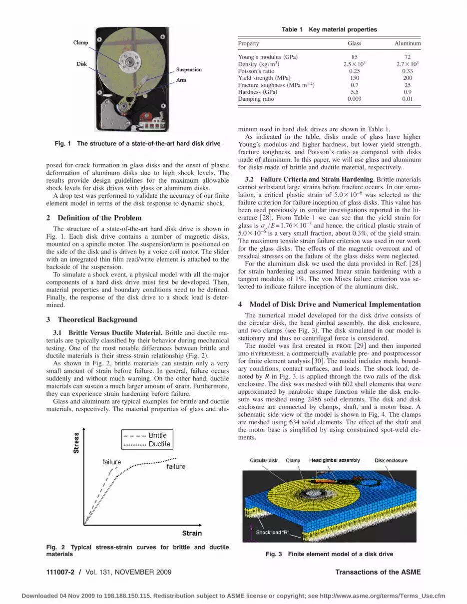
Definition of the ProblemThe structure of a state-of-the-art hard disk drive is shown in
ig. 1. Each disk drive contains a number of magnetic disks,ounted on a spindle motor. The suspension/arm is positioned on
he side of the disk and is driven by a voice coil motor. The sliderith an integrated thin film read/write element is attached to theackside of the suspension.
To simulate a shock event, a physical model with all the majoromponents of a hard disk drive must first be developed. Then,aterial properties and boundary conditions need to be defined.inally, the response of the disk drive to a shock load is deter-ined.
Theoretical Background
3.1 Brittle Versus Ductile Material. Brittle and ductile ma-erials are typically classified by their behavior during mechanicalesting. One of the most notable differences between brittle anductile materials is their stress-strain relationship �Fig. 2�.
As shown in Fig. 2, brittle materials can sustain only a verymall amount of strain before failure. In general, failure occursuddenly and without much warning. On the other hand, ductileaterials can sustain a much larger amount of strain. Furthermore,
hey can experience strain hardening before failure.Glass and aluminum are typical examples for brittle and ductileaterials, respectively. The material properties of glass and alu-
Fig. 1 The structure of a state-of-the-art hard disk drive
ig. 2 Typical stress-strain curves for brittle and ductile
aterials11007-2 / Vol. 131, NOVEMBER 2009
ded 04 Nov 2009 to 198.188.150.115. Redistribution subject to ASM
minum used in hard disk drives are shown in Table 1.As indicated in the table, disks made of glass have higher
Young’s modulus and higher hardness, but lower yield strength,fracture toughness, and Poisson’s ratio as compared with disksmade of aluminum. In this paper, we will use glass and aluminumfor disks made of brittle and ductile material, respectively.
3.2 Failure Criteria and Strain Hardening. Brittle materialscannot withstand large strains before fracture occurs. In our simu-lation, a critical plastic strain of 5.0�10−6 was selected as thefailure criterion for failure inception of glass disks. This value hasbeen used previously in similar investigations reported in the lit-erature �28�. From Table 1 we can see that the yield strain forglass is �y /E=1.76�10−3 and hence, the critical plastic strain of5.0�10−6 is a very small fraction, about 0.3%, of the yield strain.The maximum tensile strain failure criterion was used in our workfor the glass disks. The effects of the magnetic overcoat and ofresidual stresses on the failure of the glass disks were neglected.
For the aluminum disk we used the data provided in Ref. �28�for strain hardening and assumed linear strain hardening with atangent modulus of 1%. The von Mises failure criterion was se-lected to indicate failure inception of the aluminum disk.
4 Model of Disk Drive and Numerical ImplementationThe numerical model developed for the disk drive consists of
the circular disk, the head gimbal assembly, the disk enclosure,and two clamps �see Fig. 3�. The disk simulated in our model isstationary and thus no centrifugal force is considered.
The model was first created in PRO/E �29� and then importedinto HYPERMESH, a commercially available pre- and postprocessorfor finite element analysis �30�. The model includes mesh, bound-ary conditions, contact surfaces, and loads. The shock load, de-noted by R in Fig. 3, is applied through the two rails of the diskenclosure. The disk was meshed with 602 shell elements that wereapproximated by parabolic shape function while the disk enclo-sure was meshed using 2486 solid elements. The disk and diskenclosure are connected by clamps, shaft, and a motor base. Aschematic side view of the model is shown in Fig. 4. The clampsare meshed using 634 solid elements. The effect of the shaft andthe motor base is simplified by using constrained spot-weld ele-ments.
Table 1 Key material properties
Property Glass Aluminum
Young’s modulus �GPa� 85 72Density �kg /m3� 2.5�103 2.7�103
Poisson’s ratio 0.25 0.33Yield strength �MPa� 150 200Fracture toughness �MPa m1/2� 0.7 25Hardness �GPa� 5.5 0.9Damping ratio 0.009 0.01
Fig. 3 Finite element model of a disk drive
Transactions of the ASME
E license or copyright; see http://www.asme.org/terms/Terms_Use.cfm

iheepdafNdr
mwoFrplcstpstcw
J
Downloa
The surface of the clamps is parallel to the disk and the clamp-ng force is distributed evenly along the clamp �see Fig. 5�. Theead/gimbal assembly �see Fig. 3� is modeled using 3219 shelllements and 96 solid elements. The assembly is connected at onend to the disk enclosure through rigid elements. The slider can beositioned over the disk and contact the disk. Contact surfaces areefined between the clamp and the disk, and between the slidernd the disk. A value of 0.25 was used for the coefficient ofriction of the clamp-disk interface. The clamping force used is 20
and the slider force �see Fig. 6� when the slider is resting on theisk is 25 mN. These values represent typical values used in cur-ent disk drives.
A shock load applied to the two rails of the disk enclosure isodeled by an acceleration profile consisting of a half-sine waveith duration of 1 ms. Throughout this paper, the peak amplitudef the acceleration profile was used to identify the shock level.igure 7 presents the shock loads for five different shock levelsanging from 1000 G to 5000 G. Disk failure can occur at anyoint during a shock. When failure first occurs at a certain shockevel this level is defined as the “critical shock level.” Commer-ially available finite element software, LS-DYNA �31�, was used toimulate the effect of a given shock load on the disk and to findhe critical shock level for the range of shock loads up to 5000 Gresented in Fig. 7. During the process of finding the “criticalhock level,” we start with an arbitrary shock level and calculatehe tensile strains over the entire disk surface throughout the ac-eleration cycle for time steps of 0.01 ms. If no failure is detectede increase the shock level in steps of 100 G until first failure can
Fig. 4 Schematic side view of the model
Fig. 5 Finite element model of the disk clamp
Fig. 6 Point force applied by the slider on the disk
ournal of Mechanical Design
ded 04 Nov 2009 to 198.188.150.115. Redistribution subject to ASM
be observed within a time interval of �0.05 ms about the 0.5 mstime corresponding to the peak amplitude of the acceleration pro-file. In case this first failure occurs below the peak amplitude,outside the �0.05 ms time interval, the acceleration value at thisinstant is selected as the shock level for the next trial.
A number of cases were investigated numerically for shocklevels higher than the critical one. This was done to study propa-gation of cracks in glass disks and plastic strain evolution in alu-minum disks, beyond their failure inception.
For glass disks a critical strain of 5.0�10−6 was selected as thefailure criterion. Cracks start where the strain exceeds this level.The calculated plastic tensile strain is compared with the value ofthe critical plastic strain at each time step. If the plastic tensilestrain of any element reaches the critical plastic strain, this ele-ment is deleted, and crack propagation is initiated. As the shockevolves in time the plastic strain of additional elements exceedsthe critical value. These elements are also deleted and the crackpropagates. It should be noted here that crack propagation canalso be modeled based on fracture mechanics.
For aluminum disks, plastic hardening based on the radial re-turn plasticity approach by Belytschko et al. �27� is consideredafter the maximum von Mises stress reaches the yield strength.This model is able to deal with any type of hardening and istherefore suitable for general plastic behavior in finite elementanalyses. The numerical implementation for the radial return ap-proach is described in detail in Ref. �32�. Basically, the modelpresents the relation between stress and strain in the plastic regimeby a piecewise linear approximation. It should be noted here thatother less sophisticated plasticity laws could also be used.
The radial return plasticity procedure consists of the followingsteps:
�a� At each time step the plastic strain increment ��P is cal-culated using
��P =s� − �y
n
3G + EP �1�
where s� is an effective trial stress, defined by s�
= �1.5sij�n+1sij
�n+1�1/2. Here sij�n+1 is the trial stress at the
yield surface for time step n+1, �yn is the yield strength at
time step n, G is the shear modulus, and EP is the step-wise linear tangent modulus in the plastic regime.
�b� The plastic strain �n+1P is updated for time step n+1 using
�n+1P = �n
P + ��P �2��c� n+1
Fig. 7 Shock load versus time as applied to the two rails of thedisk enclosure
The yield strength �y is calculated for time step n+1 by
NOVEMBER 2009, Vol. 131 / 111007-3
E license or copyright; see http://www.asme.org/terms/Terms_Use.cfm

5
alFasgdutawtTs
gcadcitdpcTdtoFpt
ld
1
Downloa
�yn+1 = �y
n + EP��P �3��d� The scale factor m, using the yield strength at time step
n+1, is computed as
m =�y
n+1
s��4�
�e� Finally, the deviatoric stress sijn+1 for time step n+1 is
returned to the yield surface as
sijn+1 = msij
�n+1 �5�
Drop Test Results and Model VerificationIn order to validate the finite element model described in Sec. 4special experimental drop test setup was built and used in our
aboratory. The experimental setup, as shown schematically inig. 8, consists of a drop tester, a LDV, a high pass filter, a datacquisition system, and a digital computer. The drop tester con-ists of a disk enclosure �without the head gimbal assembly�,uide rails, and a base plate with a damper on its top surface. In arop test, a disk is clamped to the disk enclosure, which is liftedp to a certain height from where it is released and dropped to hithe base plate. The laser beam from the LDV can be aimed eithert the disk or the disk enclosure. As soon as the disk enclosureith the clamped disk is released the data acquisition system is
riggered and starts capturing the filtered signal from the LDV.he captured signal is transmitted to a digital computer for analy-is.
For the validation of the numerical model, we used standardlass disks with 27.4 mm diameter. First, a glass disk waslamped to the disk enclosure and dropped from a fixed height ofbout 1 m. The acceleration of the disk enclosure was obtained byifferentiating the velocity obtained from the LDV. A typical ac-eleration profile of the top surface of the disk enclosure is plottedn Fig. 9. The dynamics of the acceleration shown in Fig. 9 isypical to drop impact tests �33�. As can be seen the shock loadiffers from the ideal sine wave shock load shown in Fig. 7. Theeak shock amplitude was about 1000 G, followed by small os-illations �positive shock load represents upward acceleration�.he same test was repeated with the laser beam aimed at the outeriameter of the disk. The displacement �obtained by integratinghe time-dependent velocity measured by the LDV� at the diskuter diameter, during the shock load shown in Fig. 9, is plotted inig. 10�a�. As can be observed, the maximum peak to peak am-litude of the disk displacement was 36 �m and decreased asime evolves.
The shock load shown in Fig. 9 was used as the input shockoad for the numerical model described in Sec. 4 above. A glass
Fig. 8 A schematic of the experimental setup
isk identical to the one used in the drop test was analyzed. The
11007-4 / Vol. 131, NOVEMBER 2009
ded 04 Nov 2009 to 198.188.150.115. Redistribution subject to ASM
calculated displacement at the disk outer diameter is plotted inFig. 10�b�. As indicated in this figure, the theoretical maximumpeak to peak amplitude of the disk displacement at its outer diam-eter is 34 �m, which is in fair agreement with the experimentalresults shown in Fig. 10�a�. The differences between the experi-mental and theoretical results can be attributed to different geom-etries of the experimental disk enclosure, which includes twobearings to allow sliding of the disk enclosure on the guiding rails,and to the presence of a damping pad �see Fig. 8� that is absent inthe numerical model. The comparison between experimental andnumerical results shown in Fig. 10 verifies the accuracy of thenumerical model in a quantitative manner. Interestingly, the peakto peak displacement shown in Fig. 10 is much smaller that theaxial clearance �being on the order of 100 �m for a 27.4 mmdiameter disk� between the disk surface and the surface of theload unload �LUL� ramp used in modern hard disk drives. Hence,although not considered in our analysis, the LUL ramp most likelywould not contribute to disk failure by impacting the disk.
6 Crack Formation in Glass Disks and Plastic Defor-mation in Aluminum Disks
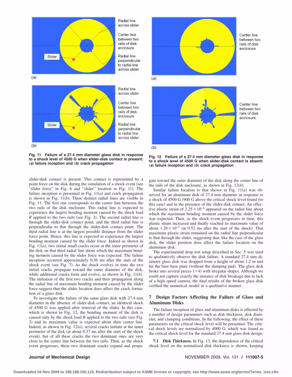
Failure of a glass disk with 27.4 mm diameter in response to ashock level of 4500 G �which is 500 G above the critical shocklevel found for this case� is shown in Fig. 11 for the case when
Fig. 9 An experimental drop test acceleration profile of thedisk enclosure
Fig. 10 Displacement of the disk obtained „a… from the drop
test experiment and „b… from the numerical model.Transactions of the ASME
E license or copyright; see http://www.asme.org/terms/Terms_Use.cfm
sp“fiFteRtptfbFtiisiwTtft
dowc3Ipece
Ft„
J
Downloa
lider-disk contact is present. This contact is represented by aoint force on the disk during the simulation of a shock event �seeslider force” in Fig. 6 and “slider” location in Fig. 11�. Theailure inception is presented in Fig. 11�a� and crack propagations shown in Fig. 11�b�. Three distinct radial lines are visible inig. 11. The first one corresponds to the center line between the
wo rails of the disk enclosure. This radial line is expected toxperience the largest bending moment caused by the shock load
applied to the two rails �see Fig. 3�. The second radial line ishrough the slider-disk contact point, and the third radial line iserpendicular to that through the slider-disk contact point. Thehird radial line is at the largest possible distance from the sliderorce point. Hence, this line is expected to experience the largestending moment caused by the slider force. Indeed as shown inig. 11�a�, two initial small cracks occur at the inner perimeter of
he disk on that third radial line about which the maximum bend-ng moment caused by the slider force was expected. The failurenception occurred approximately 0.36 ms after the start of thehock event �see Fig. 7�. As the shock evolves in time the twonitial cracks propagate toward the outer diameter of the disk,hile additional cracks form and evolve, as shown in Fig. 11�b�.he initiation of the first two cracks and their propagation along
he radial line of maximum bending moment caused by the sliderorce suggest that the slider location does affect the crack forma-ion of a glass disk.
To investigate the failure of the same glass disk with 27.4 mmiameter in the absence of slider-disk contact, an identical shockf 4500 G was applied after removal of the slider. In this case,hich is shown in Fig. 12, the bending moment of the disk is
aused only by the shock load R applied to the two rails �see Fig.� and its maximum value is expected about their center line.ndeed, as shown in Fig. 12�a�, several cracks initiate at the innererimeter of the disk �at about 0.37 ms after the start of the shockvent�, but of all these cracks the two dominant ones are verylose to the center line between the two rails. Then, as the shock
ig. 11 Failure of a 27.4 mm diameter glass disk in responseo a shock level of 4500 G when slider-disk contact is present:a… failure inception and „b… crack propagation
vent progresses, these two dominant cracks expand and propa-
ournal of Mechanical Design
ded 04 Nov 2009 to 198.188.150.115. Redistribution subject to ASM
gate toward the outer diameter of the disk along the center line ofthe rails of the disk enclosure, as shown in Fig. 12�b�.
Similar failure location to that shown in Fig. 11�a� was ob-served for an aluminum disk of 27.4 mm diameter in response toa shock of 4500 G �900 G above the critical shock level found forthis case� and in the presence of the slider-disk contact. An effec-tive plastic strain of 2.25�10−4 appeared on the radial line aboutwhich the maximum bending moment caused by the slider forcewas expected. Then, as the shock event progresses in time, thisplastic strain increased and finally reached its maximum value ofabout 1.28�10−3 �at 0.52 ms after the start of the shock�. Thatmaximum plastic strain remained on the radial line perpendicularto that through the slider, suggesting that, like the case of the glassdisk, the slider position does affect the failure location on thealuminum disk.
The experimental drop test setup described in Sec. 5 was usedto qualitatively observe the disk failure. A standard 27.4 mm di-ameter glass disk was dropped from a height of about 1.2 m andhit the bare base plate �without the damping pad�. The glass diskbroke into several pieces ��4� with irregular shapes. Although wecould not capture exactly the instance of disk breakage due to lackof a high speed camera, the final results of the broken glass diskverified the numerical model in a qualitative manner.
7 Design Factors Affecting the Failure of Glass andAluminum Disks
The failure inception of glass and aluminum disks is affected bya number of design parameters such as disk thickness, disk diam-eter, and clamping conditions. In the following, the effect of theseparameters on the critical shock level will be presented. The criti-cal shock levels are normalized by 4000 G, which was found asthe critical shock level for the standard 27.4 mm glass disk design.
7.1 Disk Thickness. In Fig. 13, the dependence of the critical
Fig. 12 Failure of a 27.4 mm diameter glass disk in responseto a shock level of 4500 G when slider-disk contact is absent:„a… failure inception and „b… crack propagation
shock level on the normalized disk thickness is shown, keeping
NOVEMBER 2009, Vol. 131 / 111007-5
E license or copyright; see http://www.asme.org/terms/Terms_Use.cfm

tci2lcrt
t1Nsoc
io7ash
Fs
Fs
F„
1
Downloa
he other entire design parameters constant �clamp outer diameter,lamping force, and disk diameter�. The disk thickness is normal-zed by the “standard” value of 0.381 mm corresponding to the7.4 mm disk. From Fig. 13, we observe that the critical shockevel for failure inception in both glass and aluminum disks in-reases with disk thickness. Unfortunately, thicker disks, whichesist shock failure better, are undesirable since increased diskhickness increases the stack-height of the disk drive.
7.2 Clamping Conditions. The effect of clamping force onhe failure inception of glass and aluminum disks is shown in Fig.4. The clamping force is normalized with a standard value of 20. We observe that the fracture inception in a glass disk is insen-
itive to the clamping force. However, for aluminum disks, webserve a slight decrease in the critical shock level with an in-rease in the clamping force.
The effect of the outer diameter of the clamp on the failurenception in glass and aluminum disks is shown in Fig. 15. Theuter diameter of the clamp is normalized with a standard value of.62 mm. We observe that the critical shock level for both glassnd aluminum disks increases with an increase in the nondimen-ional outer diameter of the clamp, i.e., the diameter of the clampas a strong effect on the critical shock level.
ig. 13 Critical shock level versus disk thickness „other de-ign parameters are kept constant…
ig. 14 Critical shock level versus clamping force „other de-ign parameters are kept constant…
ig. 15 Critical shock level versus clamp outer diameter
other design parameters are kept constant…11007-6 / Vol. 131, NOVEMBER 2009
ded 04 Nov 2009 to 198.188.150.115. Redistribution subject to ASM
7.3 Disk Form Factor. Since it is impractical to change thedisk diameter alone, without simultaneous structural changes inthe entire disk drive system, we will use the form factor ratherthan the disk diameter as another design parameter. To investigatethe effect of the form factor on failure inception, we have repeatedthe previous simulations for a series of form factors �Fig. 16�. Inthese simulations we have scaled all geometrical parameters bythe same ratio �the form factor�. In addition, the clamping forcewas scaled by the same ratio as the form factor. To leave the flyingcharacteristics unchanged, the load applied by the head gimbalassembly on the slider was kept constant at 25 mN.
The dependence of the critical shock level on the normalizedform factor at failure inception of glass and aluminum disks isshown in Fig. 17. The disk form factor is normalized with theform factor of the 27.4 mm disk. Clearly, the form factor has themost significant effect on the maximum permissible shock level.The critical shock level increases sharply with a decrease in thedisk form factor for both glass and aluminum disks, i.e., thesmaller the disk form factor the higher is its resistance to failure.This would be expected because of the smaller bending momentsproduced by either the rails of the enclosure or the slider pointforce.
8 DiscussionFrom the simulation results shown in Sec. 7, we observe that
the critical shock level increases when the disk thickness or theouter diameter of the clamp increases or when the disk form factor�and thereby the disk diameter� decreases. To explain these re-sults, we examined a somewhat similar case of “bending of a flatcircular plate” �see Fig. 18�. The outer edge of the plate is free butits inner edge is clamped �34�. Here, the inner radius b of the platerepresents the outer radius of our disk clamp. The outer radius aand the thickness t of the plate represent our disk outer radius andthickness, respectively. A load per unit area q is applied to theplate.
Fig. 16 Finite element models for hard disk drives with differ-ent form factors
Fig. 17 Critical shock level versus disk form factor
Transactions of the ASME
E license or copyright; see http://www.asme.org/terms/Terms_Use.cfm

iR
Tt
w
Er�Ea
Ima
Iqcu
Te
Fe
J
Downloa
The maximum bending moment per unit length at the clampednner circumference of the disk, at radial location b, is given inef. �34� by
Mrb =qa2
C8� C9
2ab�a2 − b2� − L17� �6�
he parameters C8, C9, and L17 in Eq. �6� are general functionshat are also given in Ref. �34� and can be expressed at x=b by
C8 =1
2�1 + � + �1 − ���b
a�2� �7a�
C9 =b
a1 + �
2ln
a
b+
1 − �
4�1 − �b
a�2� �7b�
L17 =1
41 −
1 − �
4�1 − �b
a�4� − �b
a�2�1 + �1 + ��ln
a
b�
�7c�
here � is the Poisson’s ratio. Equation �7� can be rewritten as
Mrb = qa2�C9
C8
a
2b�1 − �b
a�2� −
L17
C8� �8�
quation �8� can be simplified by noting that typical values of theatio of the inner to outer diameter of hard disk drives give b /a
0.2. Hence, higher orders of the ratio b /a can be neglected inqs. �7a�–�7c� compared with 1. Thus, C9 /C8 and L17 /C8 can bepproximated as
C9
C8�
b
a�1 + �
2ln
a
b+
1 − �
4�
1
2�1 + ��
=2b
a�1
2ln
a
b+
1 − �
4�1 + ��� �9a�
L17
C8�
1
4�1 −
1 − �
4�
1
2�1 + ��
=3 + �
8�1 + ���9b�
nserting Eqs. �9a� and �9b� into Eq. �8�, the maximum bendingoment per unit length at the inner circumference of a disk is
pproximated as
Mrb � qa2��1
2ln
a
b+
1 − �
4�1 + ��� −3 + �
8�1 + ���= qa2�1
2ln
a
b−
1 + 3�
8�1 + ��� �10�
n the absence of any external loading, the load per unit area q is=gt, where is the material density of the disk and g is theonstant of gravity. Hence, the maximum bending moment pernit length on this plate due to its own mass is calculated as
Mrb � gta2�1
2ln
a
b−
1 + 3�
8�1 + ��� �11�
he maximum stress caused by the own mass of the plate can be
ig. 18 Bending of a flat circular plate „outer edge free, innerdge clamped… †31‡
xpressed as �34�
ournal of Mechanical Design
ded 04 Nov 2009 to 198.188.150.115. Redistribution subject to ASM
�max = Mrb
6
t2 �6ga2
t�1
2ln
a
b−
1 + 3�
8�1 + ��� �12�
Now, if we increase the acceleration �gravity� to a point where�max becomes equal to the yield strength, we can consider thisacceleration as being the critical shock level. Hence, consideringonly the geometrical parameters in Eq. �12�, the relationship be-tween the critical shock level and the geometrical parameters canbe expressed by
Gcrit t
a2�lna
b−
1 + 3�
4�1 + ����13�
From Eq. �13�, we can see that the critical shock level is linearlyproportional to the thickness t in agreement with the prediction inFig. 13, where a thicker disk can withstand higher shock levels.Similarly, the critical shock level in Eq. �13� is increased when theinner radius b of the plate increases. This trend is in agreementwith the results shown in Fig. 15, where an increasing clampdiameter results in a higher critical shock level.
From Eq. �13� we can see that keeping a /b and t /a constant,the critical shock level is inversely proportional to the outer radiusa. This correlates with the results shown in Fig. 17.
Increasing the clamp outer diameter reduces the available re-cording area, while increasing the disk thickness increases thestack height. Both effects are undesirable in the design of diskdrives and therefore a compromise is required among all thoseparameters.
9 ConclusionThe failure mechanism of small form factor hard disks due to
high shock levels caused by accidental drop was investigated. Itwas found that failure inception, in both brittle and ductile mate-rial disks, occurs at the inside perimeter of the disk on a radial lineabout which the bending moment is maximum. When the sliderrests on the disk this radial line is perpendicular to that across theslider, otherwise, this radial line is the center line of the two rails.
The effect of several design parameters on the critical shocklevel at which failure incepts was investigated. It was found thatan increase in the outer diameter of the clamp and an increase inthe disk thickness cause an increase in the critical shock level. Thecritical shock level is affected strongly by the disk form factor andsharply increases when the disk becomes smaller. The numericalresults were compared with a simplified analytical model for staticbending of a flat circular plate and were found in good qualitativeagreement.
Disk drive makers are seeking more recordable area in a disk,in addition to stacking more disks into drives so as to increasecapacity for each drive. This study indicates that a design com-promise is needed between increase in drive capacity and criticalshock level in terms of clamp diameter and disk thickness.
References�1� Schreck, E., 1994, “Magnetic-Readback-Mapping and its Application to the
Slider/Disc Interface Damage Due to Shock Impact,” STLE Proceedings onTribology and Mechanics of Magnetic Storage Systems Symposia, IX, pp.5–10.
�2� Allen, A. M., and Bogy, D. B., 1996, “Effects of Shock on the Head DiskInterface,” IEEE Trans. Magn., 32, pp. 3717–3719.
�3� Edwards, J. R., 1999, “Finite Element Analysis of the Shock Response andHead Slap Behavior of a Hard Disk Drive,” IEEE Trans. Magn., 35, pp.863–867.
�4� Lee, S. J., Hong, S. K., and Lee, J. M., 2001, “A Study of Shock-ResistanceDesign of Suspension Subjected to Impulsive Excitation,” IEEE Trans. Magn.,37, pp. 826–830.
�5� Lin, C. C., 2002, “Finite Element Analysis of a Computer Hard Disk DriveUnder Shock,” ASME J. Mech. Des., 124, pp. 121–125.
�6� Zeng, Q. H., and Bogy, D. B., 2002, “Numerical Simulation of Shock Re-sponse of Disk-Suspension-Slider Air Bearing Systems in Hard Disk Drives,”Microsyst. Technol., 8, pp. 289–296.
�7� Jayson, E. M., Murthy, J., Smith, P. W., and Talke, F. E., 2002, “Shock and
Head Slap Simulations of Operational and Nonoperational Hard Disk Drives,”NOVEMBER 2009, Vol. 131 / 111007-7
E license or copyright; see http://www.asme.org/terms/Terms_Use.cfm

1
Downloa
IEEE Trans. Magn., 38, pp. 2150–2152.�8� Murthy, A. N., Feliss, B., Gillis, D., and Talke, F. E., 2006, “Experimental and
Numerical Investigation of Shock Response in 3 12 and 2 1
2 Inch Form FactorHard Disk Drives,” Microsyst. Technol., 12, pp. 1109–1116.
�9� Feliss, B., Murthy, A. N., and Talke, F. E., 2007, “Microdrive Operational andNon-Operational Shock and Vibration Testing,” Microsyst. Technol., 13, pp.1015–1021.
�10� Bhargava, P., and Bogy, D. B., 2007, “Numerical Simulation of Operational-Shock in Small Form Factor Hard Disk Drives,” ASME J. Tribol., 129, pp.153–160.
�11� Bless, S. J., Brar, N. S., Kanel, G., and Rosenberg, Z., 1992, “Failure Waves inGlass,” J. Am. Ceram. Soc., 75, pp. 1002–1004.
�12� Rosenberg, Z., Bourne, N. K., and Millett, J., 1996, “Direct Measurements ofStrain in Shock-Loaded Glass Specimens,” J. Appl. Phys., 79, pp. 3971–3974.
�13� Bourne, N. K., Millett, J., Rosenberg, Z., and Murray, N., 1998, “On the ShockInduced Failure of Brittle Solids,” J. Mech. Phys. Solids, 46, pp. 1887–1908.
�14� Millett, J. C. F., Bourne, N. K., and Rosenberg, Z., 2000, “Direct Measure-ments of Strain in a Shock-Loaded Lead Filled Glass,” J. Appl. Phys., 87, pp.8457–8460.
�15� Grady, D. E., 1998, “Shock-Wave Compression of Brittle Solids,” Mech.Mater., 29, pp. 181–203.
�16� Govindjee, S., Kay, G. J., and Simo, J. C., 1995, “Anisotropic Modeling andNumerical Simulation of Brittle Damage in Concrete,” Int. J. Numer. MethodsEng., 38, pp. 3611–3633.
�17� Elías, D. A., and Chiang, L. E., 2003, “Dynamic Analysis of Impact Tools byUsing a Method Based on Stress Wave Propagation and Impulse-MomentumPrinciple,” ASME J. Mech. Des., 125, pp. 131–142.
�18� Curran, D. R., Seaman, L., and Shockey, D. A., 1987, “Dynamic Failure ofSolids,” Phys. Rep., 147, pp. 253–388.
�19� Seaman, L., Curran, D. R., and Shockey, D. A., 1976, “Computational Modelsfor Ductile and Brittle Fracture,” J. Appl. Phys., 47, pp. 4814–4826.
�20� Costin, L. S., Duffy, J., and Freund, L. B., 1977, “Fracture Initiation in Metals
11007-8 / Vol. 131, NOVEMBER 2009
ded 04 Nov 2009 to 198.188.150.115. Redistribution subject to ASM
Under Stress Wave Loading Conditions,” American Society of Testing andMeasurement, Paper Nos. STP627-EB and STP27395S.
�21� Nakamura, T., Shih, C. F., and Freund, L. B., 1985, “Elastic-Plastic Analysis ofa Dynamically Loaded Circumferentially Notched Round Bar,” Eng. Fract.Mech., 22, pp. 437–452.
�22� Nishioka, T., and Atluri, S. N., 1983, “Path-Independent Integrals, EnergyRelease Rates, and General Solutions of Near-Tip Fields in Mixed-Mode Dy-namic Fracture Mechanics,” Eng. Fract. Mech., 18, pp. 1–22.
�23� Rosakis, A. J., and Ravichandran, G., 2000, “Dynamic Failure Mechanics,”Int. J. Solids Struct., 37, pp. 331–348.
�24� Voyiadjis, G. Z., Palazotto, A. N., and Gao, X.-L., 2002, “Modeling of Metal-lic Materials at High Strain Rates With Continuum Damage Mechanics,” Appl.Mech. Rev., 55, pp. 481–493.
�25� Ma, D., and Lankarani, H. M., 1997, “A Multibody/Finite Element AnalysisApproach for Modeling of Crash Dynamic Responses,” ASME J. Mech. Des.,119, pp. 382–387.
�26� Yang, R. J., Wang, N., Tho, C. H., Bobineau, J. P., and Wang, B. P., 2005,“Metamodeling Development for Vehicle Frontal Impact Simulation,” ASMEJ. Mech. Des., 127, pp. 1014–1020.
�27� Belytschko, T., Liu, W. K., and Moran, B., 2000, Nonlinear Finite Elementsfor Continua and Structures, Wiley, New York.
�28� 2003, DYNA Models for Crash Simulation of Automobiles, Insurance Institutefor Highway Safety.
�29� 2004, PRO/ENGINEER User Manual, Parametric Technology Corporation,Needham, MA.
�30� 2002, HYPERMESH User Manual, Altair Computing Inc., Troy, MI.�31� 2003, LS-DYNA User Manual, Livermore Software Technology Corporation,
Livermore, CA.�32� Hallquist, J. O., 1998, LS-DYNA Theoretical Manual, Livermore Software
Technology Corporation, Livermore, CA.�33� Wong, E. H., 2005, “Dynamics of Board-Level Drop Impact,” ASME J. Elec-
tron. Packag., 127, pp. 200–207.�34� Young, W. C., and Budynas, R. G., 2002, Roark’s Formulas for Stress and
Strain, 7th ed., McGraw-Hill, New York.
Transactions of the ASME
E license or copyright; see http://www.asme.org/terms/Terms_Use.cfm


